macro and micro structural characteristics of dissimilar ... · the joint integrity ... mechanical...
TRANSCRIPT

Abstract— This paper reports the effect of welding parameters on the macro and micro structural characteristics of friction stir welded butt joints of dissimilar aluminum alloy plates between AA7075-T651 and AA6061-T651.The base material AA6061-T651 was placed in advancing side (AS) whereas AA7075-T651 placed in retreating side (RS) respectively. The Friction stir welded materials were joined under three different tool rotational speeds (800,900 and 1,000 rpm) and three welding speeds (90, 100 and 110 mm/min), which are the two prime joining parameters in FSW. The axial load and the tilt angle parameters are kept constant at 12kN & 0º. Three different pin profiles (Taper cylindrical threaded, Taper square threaded and Square) tools were used to consolidate the weld. The welds qualities were evaluated through optical and Scanning electron microscopy. The better mixing of both materials and good strength were achieved for the process parameters 900rpm, 90mm/min with Taper cylindrical threaded tool.
Keywords—frictions stir welding, macrographs, micrographs, Scanning Electron Microscopy
I. INTRODUCTION
N recent years, demands for light weight and high strength sheets such as aluminum alloys have increased
steadily in aerospace, aircraft and automotive applications due to their extra-ordinary strength to weight ratio with their resistance properties in adverse environments. Friction stir welding (FSW) process is a solid state joining technique considered to be the significant development over the past two decades which was invented and validated at the welding institute (TWI), United Kingdom in the year 1991[1].The FSW process is explained using Fig.1.It gives the conceptual idea of friction stir welding process for the two plates with butt joint configuration. In this process a non consumable tool is to be plunged into the faying surfaces of the plates with rotation and also it moves along the joint line for weld consolidation. The joint integrity depends upon the tool geometry nature used in this process.
Manuscript received March 01, 2013; revised March 28, 2013. Mr S.Ravikumar is a Lecturer in the Department of Mechanical and
Production, Sathyabama University, Chennai, Tamilnadu, India,2007, (Phone:+91-9444227162; e-mail:[email protected]).
Dr Vaddi. Seshagiri Rao is a Professor and Head in the department of Mechanical Engineering, St.Joseph college of Engineering, Chennai, Tamilnadu, India, 1997, (Phone +91- 9444069916; email: [email protected]).
Mr R.V.Pranesh is a Undergraduate student in the Department of Mechanical and Production, Sathyabama University, Chennai, Tamilnadu, India,2007, (Phone: +91- 9840906066, [email protected]).
The tool pin and shoulder are helpful for heat generation, and material mixing by stirring producing the joint. In this process no melting occurs and the heat is generated internally by means of friction between the material-tool interface and the plastic deformation takes place without pre or post heating. Materials with different aluminium alloys can be welded together with a least alteration in mechanical properties due to no melting. Material flow mechanism explained with the dominant parameters rotational speed, welding speed and axial force [2]. There are two different modes of material flow regimes involved in the friction stir weld formation; namely “pin-driven flow” and “shoulder-driven flow”. These two material flow regimes merge together to form a defect-free weld. Studies have been conducted to characterize the result of microstructure in welds especially in aluminium alloys where the weld nugget was fully recrystallized with good material flow [3-4]. In the FSW process, parameter selection and tool geometry are among the key factors that determine the quality of the fabricated joint. Adjusting the values of different parameters, such as welding speed, rotational speed, tilt angle, and pin geometry, could lower the forces exerted from the TMAZ section to the tool. The plastic flow is responsible for obtaining a weld with high tensile strength and fewer defects and therefore the tool geometry plays an important role in achieving a high-quality weld. K. Elangovan et al [5] referred out of the three welded joints, the joints fabricated by FSW process exhibited higher strength values and the enhancement in strength value is approximately 34% compared to GMAW joints, and 15% compared to GTAW joints. P Bahemmat et al [10] investigates the mechanical, micro- and macro structural characteristics of the friction-stir welded dissimilar joints of AA6061-T6 and AA7075-T6 alloys.
Fig.1 Schematic diagram of friction stir welding
Macro and Micro Structural Characteristics of Dissimilar Friction Stir Welded AA7075 T651-
AA6061 T651 Butt Joint S.Ravikumar, Member, IAENG, V.Seshagiri Rao, R.V.Pranesh, Member, IAENG
I
Proceedings of the World Congress on Engineering 2013 Vol I, WCE 2013, July 3 - 5, 2013, London, U.K.
ISBN: 978-988-19251-0-7 ISSN: 2078-0958 (Print); ISSN: 2078-0966 (Online)
WCE 2013
This research reveals that there are severe defects in the
joint fabricated at a welding speed of 160 mm/min. In addition, some small defects are found at higher magnification in the joints made at a speed of 120 mm/min. Many studies have been conducted to characterize the resulting microstructure in welds especially in dissimilar aluminium alloys [6-9]. Many researchers studied and reported the base materials microstructure and its properties [11-12]. However, there are not enough literatures on microstructural characterization of dissimilar materials especially on aluminium alloys between 6000 and 7000 series. The aim of this paper is to present and report the results of micro and macro structural characteristics of dissimilar welds of aluminium alloys between AA7075-T651 and AA6061-T651 produced at different welding parameters.
II. EXPERIMENTAL SET-UP
The Friction stir welds between AA7075-T651 and AA6061-T651 aluminium alloys were produced at Coimbatore Institute of Technology, Tamilnadu, India using FSW machine with hydraulic power pack motor of 2.2kW /440V with 3000 rpm maximum rotational speed; 5000 mm/min as X axis rapid traverse speed and maximum axial thrust as 50kN. The thicknesses of both plates were 6.35mm. The plates were in a butt joint configuration and the welding process was carried out normal to the rolling direction of the plate. The dimensions of the aluminium alloy plates are 100 mm length and 50 mm width. The welding process was accomplished at three rotational speeds,800,900 and 1000 rpm, three welding speeds, 90,100 and 110 mm/min keeping axial load 12 kN and tilt angle as 0º as constant. AA 6061-T651 placed in Advancing side whereas AA7075-T651 in retreating side. Three different pin profiles (Taper cylindrical threaded (TCT), Taper square threaded (TST) and Simple Square (SS) tools used were machined from H13 tool steel and were hardened to 55HRC.The weld were characterized using DE-WINTOR inverted trinocular metallurgical microscope, Met Mech Engineers, Chennai and Scanning Electron Microscope (SEM) Hitachi S-3400N make from Anna University, Chennai, Tamilnadu, India. studies of the chemical and mechanical properties were carried out and the values are tabulated in I & II.
TABLE I CHEMICAL COMPOSITION FOR 6061-T651 & 7075-T651
ALUMINIUM ALLOYS
TABLE II MECHANICAL PROPERTIES FOR AA6061-T651 & AA7075 -
T651ALUMINIUM ALLOYS
III. RESULTS AND DISCUSSION
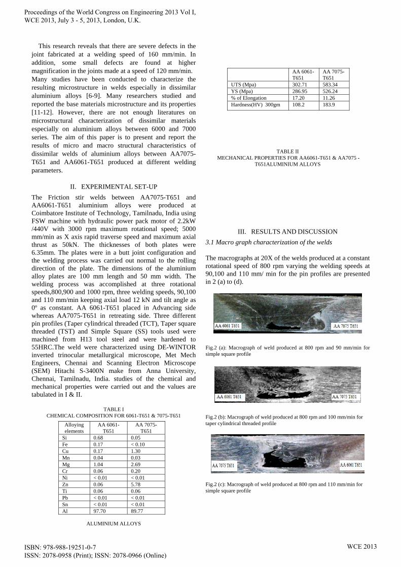
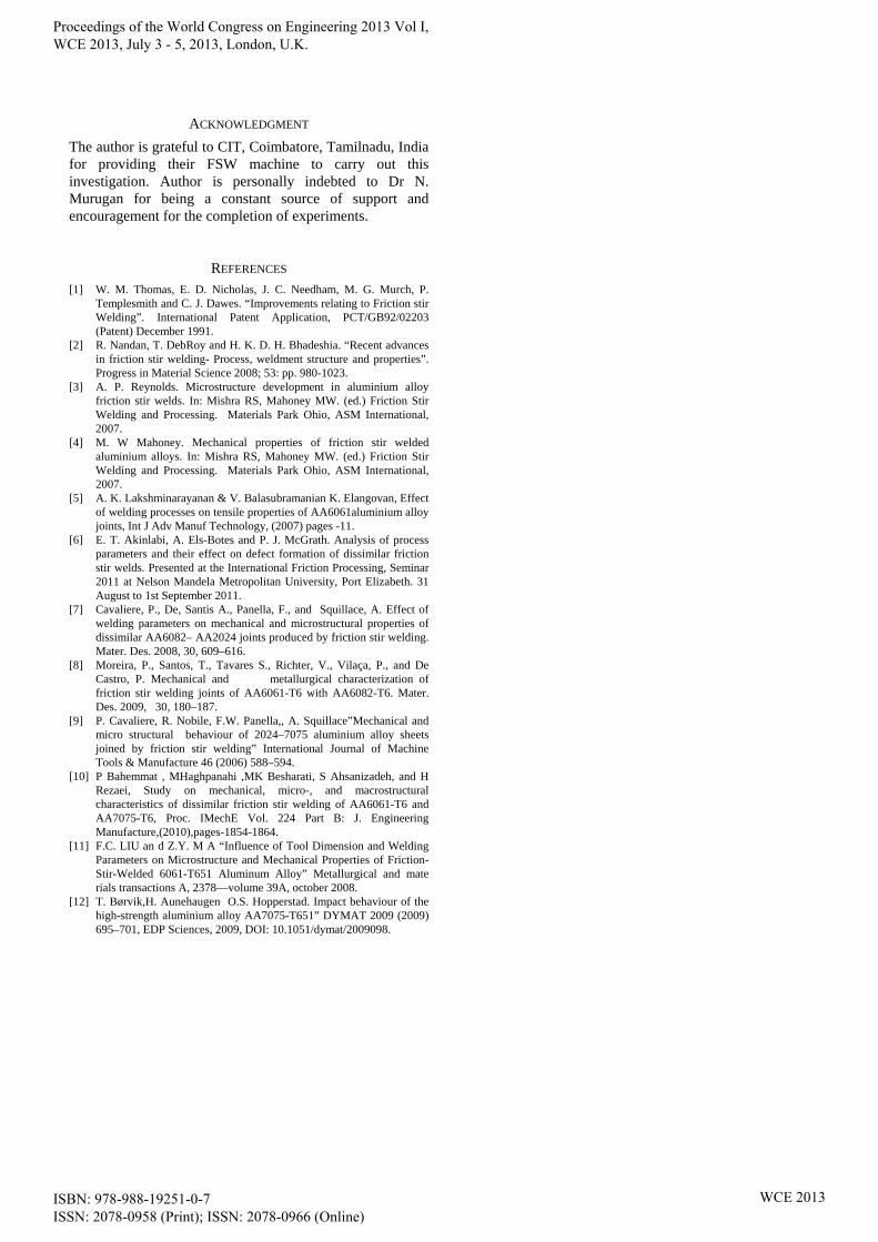
3.1 Macro graph characterization of the welds The macrographs at 20X of the welds produced at a constant rotational speed of 800 rpm varying the welding speeds at 90,100 and 110 mm/ min for the pin profiles are presented in 2 (a) to (d).
Fig.2 (a): Macrograph of weld produced at 800 rpm and 90 mm/min for simple square profile
Fig.2 (b): Macrograph of weld produced at 800 rpm and 100 mm/min for taper cylindrical threaded profile
Fig.2 (c): Macrograph of weld produced at 800 rpm and 110 mm/min for simple square profile
Alloying elements
AA 6061-T651
AA 7075-T651
Si 0.68 0.05 Fe 0.17 < 0.10 Cu 0.17 1.30 Mn 0.04 0.03 Mg 1.04 2.69 Cr 0.06 0.20 Ni < 0.01 < 0.01 Zn 0.06 5.78 Ti 0.06 0.06 Pb < 0.01 < 0.01 Sn < 0.01 < 0.01 Al 97.70 89.77
AA 6061-T651
AA 7075-T651
UTS (Mpa) 302.71 583.34 YS (Mpa) 286.95 526.24 % of Elongation 17.20 11.26 Hardness(HV) 300gm 108.2 183.9
Proceedings of the World Congress on Engineering 2013 Vol I, WCE 2013, July 3 - 5, 2013, London, U.K.
ISBN: 978-988-19251-0-7 ISSN: 2078-0958 (Print); ISSN: 2078-0966 (Online)
WCE 2013

Fig.2 (d): Macrograph of weld produced at 800 rpm and 100 mm/min for Taper Square threaded profile
The thickness is not reduced but materials are not mixed vertically for its full dimension due to insufficient axial load. The tunnel defect seen in all the plates at a constant rotational speed of 800 rpm with varying welding speeds and tool pin profiles. Larger tunnel defect in 2(c) and 2(d) may be due faster movement rate of the tool (110 &100 mm/min ) during the welding process which have low heat input and poor material mixing results in poor welding consolidation irrespective of tool pin profiles.
The macrographs of welds at 20X produced at a constant rotational speed of 900 rpm varying the welding speeds at 90,100 and 110 mm/min for the pin profiles are presented in Fig.3 (a) to (e).
Fig.3 (a): Macrograph of weld produced at 900 rpm and 90 mm/min for taper cylindrical threaded profile
Fig.3 (b): Macrograph of weld produced at 900 rpm and 90 mm/min for Taper Square threaded profile
Fig.3 (c): Macrograph of weld produced at 900 rpm and 100 mm/min for simple square profile.
Fig.3 (d): Macrograph of weld at 20X produced at 900 rpm and 110 mm/min for Taper Square threaded profile.
Fig.3 (e): Macrograph of weld produced at 900 rpm and 110 mm/min for taper cylindrical threaded profile.
The thickness is not reduced but materials are not mixed vertically for its full dimension due to insufficient axial load for taper cylindrical threaded and simple square pin profiles. The tunnel defect seen in all the plates (except 3 (d) where voids are seen) at a constant rotational speed of 900 rpm with varying welding speeds and tool pin profiles. Larger tunnel defect in 3(a),(c) and (e) may be due faster movement rate of the tool (110 &100 mm/min) during the welding process which have low heat input and poor material mixing results in poor welding consolidation irrespective of tool pin profiles. Smaller tunnel defect is seen in for taper square threaded pin profile 3 (b) where high degree of material mixing taken place large heating.
The macrographs of welds produced at a constant rotational speed of 1000 rpm varying the welding speeds at 90,100 and 110 mm/min for the pin profiles are presented in Fig.4 (a) to (d).
Fig.4 (a): Macrograph of weld produced at 1000 rpm and 90 mm/min for simple square profile.
Fig.4 (b): Macrograph of weld produced at 1000 rpm and 100 mm/min for taper cylindrical threaded profile.
Fig.4 (c): Macrograph of weld produced at 1000 rpm and 100 mm/min for Taper Square threaded profile.
Fig.4 (d): Macrograph of weld produced at 1000 rpm and 110 mm/min for simple square profile.
It was observed that there was no reduction in the thickness in the weld produced at 1000rpm with all welding speeds and tool pin profiles but materials are not mixed vertically for its full dimension due to insufficient axial load. The tunnel defect seen in all the plates (except 4 (c) where voids are seen) at a constant rotational speed of 800 rpm. Larger tunnel defect in 4(a) and 4(d) may be due faster movement
Proceedings of the World Congress on Engineering 2013 Vol I, WCE 2013, July 3 - 5, 2013, London, U.K.
ISBN: 978-988-19251-0-7 ISSN: 2078-0958 (Print); ISSN: 2078-0966 (Online)
WCE 2013

rate of the tool (110 & 90 mm/min ) during the welding process which have low heat input and poor material mixing results in poor welding consolidation irrespective of tool pin profiles. The sliding motion of the tool on the surface forms larger voids in the welds. Lower welding speeds will provide high energy into the weld to thereby larger range of plastically deformed material for weld consolidation. 3.2 Microstructural characteristics of the welds Typical micrographs reveal important features in some of the interfacial regions of the welds produced by this characterization work are hereby presented below.Fig.5 (a) presents the macro and microstructure of the joint interface of the weld produced at 900 rpm and 90mm/min. It was observed that the joint (Fig.5 (a)) is characterized with the FSW zone where alternate layers of 7075 alloy and 6061 alloys have undergone fusion. The macro structure represents the precipitated particles in both have become larger due to heat and stress. The SEM image shows the center region of the nugget Zone. The zone indicates a good fusion of the 7075 and 6061 to produce alternate layers with fine grains. The broad band is from 7075 and the light dull areas are from 6061 alloy.
Fig.5 (a): Macro and micro structure of weld produced at 900 rpm and 90 mm/min for Taper cylindrical threaded profile.
Fig.5 (b) presents the macro and microstructure of the joint interface of the weld produced at 900 rpm and 110mm/min. It was observed that the joint (Fig.5 (b)) is characterized with the FSW zone where alternate layers of 7075 alloy and 6061 alloys have undergone fusion. The macro structure represents the precipitated particles in both have become larger due to heat and stress. The SEM image shows the TMT zone of the 7075 with the formation of the onion rings with 6061 alloy.
Fig.5 (b): Macro and microstructure produced at 900 rpm and 110 mm/min for Taper Square threaded profile.
Fig.5 (c): Macrograph of weld at 20X produced at 800 rpm and 90 mm/min for Simple Square profile.
Fig.5 (c) presents the macro and microstructure of the joint interface of the weld produced at 800 rpm and 90mm/min. It was observed that the joint (Fig.5 (c)) is characterized with the FSW zone where alternate layers of 7075 alloy and 6061 alloys have undergone fusion. The macro structure represents the precipitated particles in both have become larger due to heat and stress The SEM image shows the TMT zone which consists of alternate rings of 7075 and 6061 alloys. The grains are fine and could not be resolved at higher magnifications.
IV. CONCLUSION
The parameter combinations used in the dissimilar FSW of AA7075 & AA6061 in which 900 rpm and 90 mm/min for Taper cylindrical threaded profile and 800 rpm and 90 mm/min for Simple Square profile have given substantial values in terms of tensile strengths. The parameters 900 rpm and 110 mm/ min for Taper Square threaded profile have yielded lower strength. The reasons for the lower value can be attributed to the poor fusion of the two plates and this is evident from the macro images which show larger discontinuity at the butt area. Comparison of the hardness at the identical locations also shows lower values at the FSW regions. The fracture image of 800 rpm and 90 mm/min (Simple Square profile) specimen shows the presence of fine dimples evenly present at the FSW zone. The higher elongation of the specimen is justified by the presence of fine crest and troughs and the entire region is uniform in fracture surface. The 900 rpm and 110 mm/ min combination for Taper Square threaded profile specimen fracture shows brittle appearance and with more of un-definable areas as bandings. The corresponding optical and SEM images shows haphazard formation of the nugget zone with uneven zones of 7075 and 6061.The combinations 900 rpm and 90 mm/min (Taper cylindrical threaded profile) specimen showed close resemblances to 800 rpm and 90 mm/min (Simple Square profile) specimen in all the examinations. The lower elongation can be attributed to the presence of lower dimples with lower formation of the crest and troughs. The hardness comparison of these two specimens showed closer similarities at various identical locations of the samples. The optical microscopy images for these two specimen shows very fine and uniform grains of 7075 and 6061 alloy. The EDAX value of the 800 rpm and 90 mm/min (Simple Square profile) specimen shows the presence of all the constituents of 7075 and 6061 at the nugget zone.
Proceedings of the World Congress on Engineering 2013 Vol I, WCE 2013, July 3 - 5, 2013, London, U.K.
ISBN: 978-988-19251-0-7 ISSN: 2078-0958 (Print); ISSN: 2078-0966 (Online)
WCE 2013
ACKNOWLEDGMENT
The author is grateful to CIT, Coimbatore, Tamilnadu, India for providing their FSW machine to carry out this investigation. Author is personally indebted to Dr N. Murugan for being a constant source of support and encouragement for the completion of experiments.
REFERENCES [1] W. M. Thomas, E. D. Nicholas, J. C. Needham, M. G. Murch, P.
Templesmith and C. J. Dawes. “Improvements relating to Friction stir Welding”. International Patent Application, PCT/GB92/02203 (Patent) December 1991.
[2] R. Nandan, T. DebRoy and H. K. D. H. Bhadeshia. “Recent advances in friction stir welding- Process, weldment structure and properties”. Progress in Material Science 2008; 53: pp. 980-1023.
[3] A. P. Reynolds. Microstructure development in aluminium alloy friction stir welds. In: Mishra RS, Mahoney MW. (ed.) Friction Stir Welding and Processing. Materials Park Ohio, ASM International, 2007.
[4] M. W Mahoney. Mechanical properties of friction stir welded aluminium alloys. In: Mishra RS, Mahoney MW. (ed.) Friction Stir Welding and Processing. Materials Park Ohio, ASM International, 2007.
[5] A. K. Lakshminarayanan & V. Balasubramanian K. Elangovan, Effect of welding processes on tensile properties of AA6061aluminium alloy joints, Int J Adv Manuf Technology, (2007) pages -11.
[6] E. T. Akinlabi, A. Els-Botes and P. J. McGrath. Analysis of process parameters and their effect on defect formation of dissimilar friction stir welds. Presented at the International Friction Processing, Seminar 2011 at Nelson Mandela Metropolitan University, Port Elizabeth. 31 August to 1st September 2011.
[7] Cavaliere, P., De, Santis A., Panella, F., and Squillace, A. Effect of welding parameters on mechanical and microstructural properties of dissimilar AA6082– AA2024 joints produced by friction stir welding. Mater. Des. 2008, 30, 609–616.
[8] Moreira, P., Santos, T., Tavares S., Richter, V., Vilaça, P., and De Castro, P. Mechanical and metallurgical characterization of friction stir welding joints of AA6061-T6 with AA6082-T6. Mater. Des. 2009, 30, 180–187.
[9] P. Cavaliere, R. Nobile, F.W. Panella,, A. Squillace”Mechanical and micro structural behaviour of 2024–7075 aluminium alloy sheets joined by friction stir welding” International Journal of Machine Tools & Manufacture 46 (2006) 588–594.
[10] P Bahemmat , MHaghpanahi ,MK Besharati, S Ahsanizadeh, and H Rezaei, Study on mechanical, micro-, and macrostructural characteristics of dissimilar friction stir welding of AA6061-T6 and AA7075-T6, Proc. IMechE Vol. 224 Part B: J. Engineering Manufacture,(2010),pages-1854-1864.
[11] F.C. LIU an d Z.Y. M A “Influence of Tool Dimension and Welding Parameters on Microstructure and Mechanical Properties of Friction-Stir-Welded 6061-T651 Aluminum Alloy” Metallurgical and mate rials transactions A, 2378—volume 39A, october 2008.
[12] T. Børvik,H. Aunehaugen O.S. Hopperstad. Impact behaviour of the high-strength aluminium alloy AA7075-T651” DYMAT 2009 (2009) 695–701, EDP Sciences, 2009, DOI: 10.1051/dymat/2009098.
Proceedings of the World Congress on Engineering 2013 Vol I, WCE 2013, July 3 - 5, 2013, London, U.K.
ISBN: 978-988-19251-0-7 ISSN: 2078-0958 (Print); ISSN: 2078-0966 (Online)
WCE 2013