macromodular computer design, part 2, volume 07, … · macromodular computer design, part 2,...
TRANSCRIPT
Washington University School of MedicineDigital Commons@Becker
Technical Reports Institute for Biomedical Computing
2-1974
Macromodular Computer Design, Part 2, Volume07, Faceplate SpecificationsComputer Systems Laboratory, Washington University
Follow this and additional works at: http://digitalcommons.wustl.edu/bcl_techreports
This Technical Report is brought to you for free and open access by the Institute for Biomedical Computing at Digital Commons@Becker. It has beenaccepted for inclusion in Technical Reports by an authorized administrator of Digital Commons@Becker. For more information, please [email protected].
Recommended CitationComputer Systems Laboratory, Washington University, "Macromodular Computer Design, Part 2, Volume 07, FaceplateSpecifications" (1974). Technical Reports. Paper 12.http://digitalcommons.wustl.edu/bcl_techreports/12

MACROMODULAR
COMPUTER BESI©N
PART' 2
MANUFACTUIRING BESCIRIPTOON
VOLUME VDU
FACEPLATF SPFCUFUCATUONS
...... ?echnica_ Report No. 3_
FINAL REPORT - FEBRUARY, 1974
CONTRACT SD-302 (ARPA)
COMPUTER SYSTEMS LABORATORY
WASHINGTON UNIVERSITY
ST. LOUIS, MISSOURI

MACROMODULAR COHPUTER DESIGN
FINAL REPORT - CONTRACTSD-302
:_ FEBRUARY,1974
'ec nca Repor No. B6
PART 2 - MANUFACTURING DESCRIPTION o
VOL. VII-FACEPLATE SPECIFICATIONS
4.
,&
This work has _een supported by the Advanced ResearchProjects Agency of the Department of Defense underContract SD-302 and by the Division of Research Facilitiesand Resources of the National Institutes of Healthunder Grant RR-00396.The views and conclusions contained in this document
are those of the authors and should not be interpretedas necessarily representing the official policies,either expressed or implied, of the Advanced Research
Projects Agency or the U.S. Government.
Computer Systems LaboratoryWashington University
St. Louis, Missouri

ABSTRACT
Specifications for the construction of Macromod-
_ ular Faceplate Box assemblies are contained in this
report. Also included are all electrical and mechanical
specifications for common subassemblies. Certain
general assembly techniques are specified.
J

_ INDEX
GENERAL FACEPLATE SPECIFICATIONS
PAGES 300.0-1 thru 300.0-16
1-CELL FPB SHELL
PAGES 300.1-1 thru 300.1-19
2-CELL FPB SHELL
PAGES 300.2-1 thru 300.2-8
FACEPLATE BOX VISCERA PARTS
PAGES300.5-1 thru 300.5-28
/V-BUS SUBASSEMBLY
PAGES _300. 6-1 thru 300.6-4
FUNCTION CODE SWITCH SUBASSEMBLIES
PAGES 300.7-1 thru 300.7-5

I--_ AA--!
.5WASHINGTONUNIVERSITY
GENERALFACEPLATE SPECIFICATIONS
PAGE TITLE CHANGE
J
300_0-1 TITLE PAGE G '
300_0-2 INTRODUCTION C
300_0-3 OUTLINEOF FACEPLATEDOCUMENTATION B, D
300_0-4 MANUFACTURERS AND PART NUMBERS B
300_0-5
thru GENERAL FACEPLATE BOX WIRING SPECIFICATIONS A_, E,, F
300_0-13
30000-14 ASTRO 348 COMPONENT IDENTIFICATION F
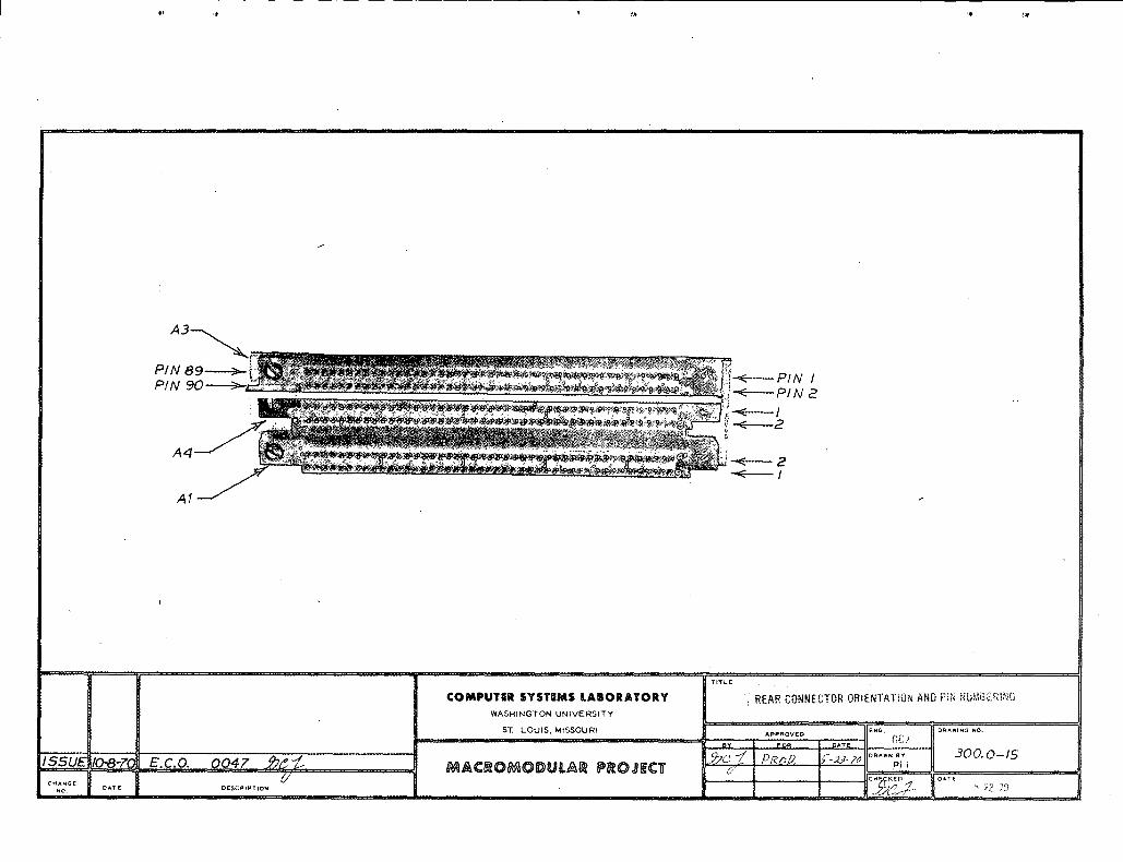
300_0-15 REAR CONNECTOR ORIENTATION AND PIN NUMBERING
300_0-16 CONTACT INSERTION FIXTURE c
rY
CHG. E.C.O. DATE APPR. CHG. E.C.O. DATE APPR. CHG. E.C.O. DATE APPR.
SSUE0047108,0 _ E 0249124,2 _:,--;-'B 0059 10-20-70 G 0277 12-7-72
C 013,5 12-2 S-"'O ._. ,,O 0235 12-13-71 ',/,(_j/_, _
MACROMODULAR SYSTEMS PROJECT
300.0-1
GENERAL SPECIFICATIONS FOR MANUFACTURE
OF MACROMODULAR FACEPLATE BOXES
°
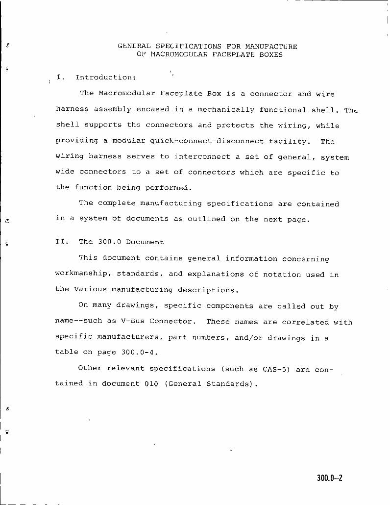
I. Introduction:I
The Macromodular Faceplate Box is a connector and wire
harness assembly encased in a mechanically functional shell. The
shell supports the connectors and protects the wiring, while
providing a modular quick-connect-disconnect facility. The
wiring harness serves to interconnect a set of general, system
wide connectors to a set of connectors which are specific to
the function being performed.
The complete manufacturing specifications are contained
in a system of documents as outlined on the next page.
II. The 300.0 Document
This document contains general information concerning
workmanship, standards, and explanations of notation used in
the various manufacturing descriptions.
On many drawings, specific components are called out by
name--such as V-Bus Connector. These names are correlated with
specific manufacturers, part numbers, and/or drawings in a
table on page 300.0-4.
Other relevant specifications (such as CAS-5) are con-
tained in document 010 (General Standards).
300 0-2
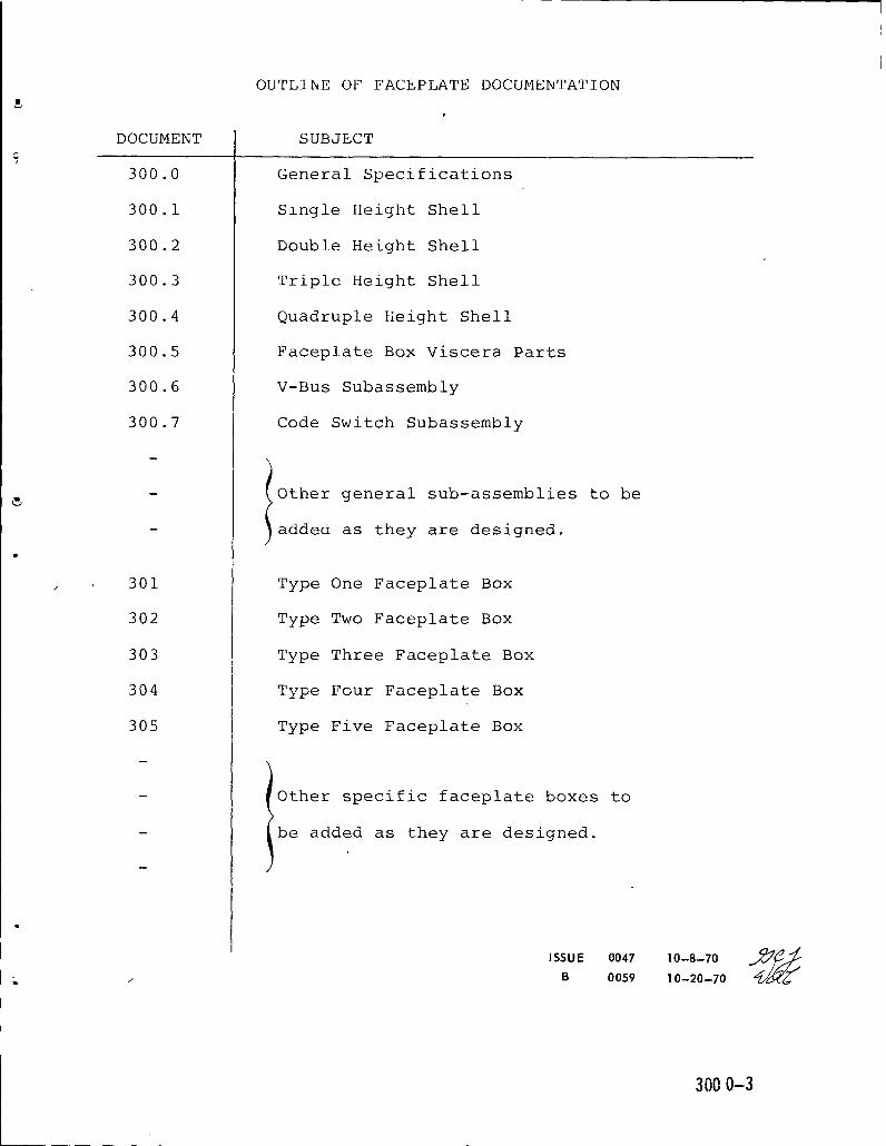
OUTLINE OF FACEPLATE DOCUMENTATION
DOCUMENT SUBJECT
300.0 General Specifications
300.1 Szngle Height Shell
300.2 Double Height Shell
300.3 Triple Height Shell
300.4 Quadruple Height Shell
300.5 Faceplate Box Viscera Parts
300.6 V-Bus Subassembly
300.7 Code Switch Subassembly
- Other general sub-assemblies to be
- added as they are designed.
301 Type One Faceplate Box
302 Type Two Faceplate Box
303 Type Three Faceplate Box
304 Type Four Faceplate Box
305 Type Five Faceplate Box
- Other specific faceplate boxes to
- be added as they are designed.
I
ISSUE 0047 10-8-70 _//_L / B 0059 10-20-70
3000-3
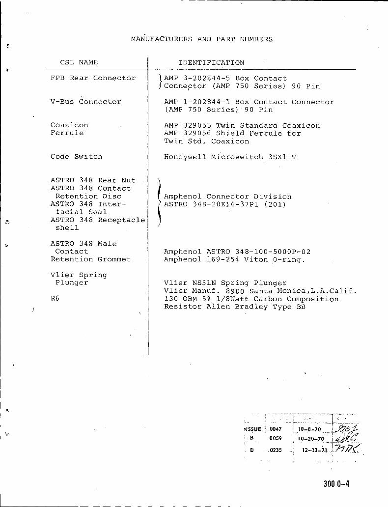
MANUFACTURERS AND PART NUMBERS!
CSL NAME IDENTIFICATION?
FPB Rear Connector tAMP 3-202844-5 Box ContactJ Connector (AMP 750 Series) 90 Pin
V-Bus Connector AMP 1-202844-1 Box Contact Connector
(AMP 750 Series) '90 Pin
Coaxicon AMP 329055 Twin Standard Coaxicon
Ferrule AMP 329056 Shield Ferrule for
Twin Std. Coaxicon
Code Switch Honeywell Mi'croswitch 3SX1-T
ASTRO 348 Rear NutASTRO 348 Contact
I
Retention Disc Amphenol Connector DivisionASTRO 348 Inter- ASTRO 348-20E14-37P1 (201)facial Seal
ASTRO 348 Receptacleshell
ASTRO 348 Male
Contact Amphenol ASTRO 348-100-5000P-02
Retention Grommet Amphenol 169-254 Viton 0-ring.
Vlier Spring
Plunger Vlier NS51N Spring Plunger
Vlier Manuf. 8900 Santa Monica,L.A.Calif.
R6 130 OHM 5% 1/8Watt Carbon Composition
! Resistor Allen Bradley Type BB
,,SSUE00aZ _L,0-_8-Z0.....i_...3_e>i'
: '- D . .0235 ' 12-13-71 ..... ;
' ' · .... i "
300,.0-4
GENERAL FACEPLATE BOX WIRING SPECIFICATION
&
I. Introduction
This document describes specifications and techniques
which are common to the several types of faceplate box wiring
subassemblies.
II. Workmanship
· These assemblies use sub-miniature connectors, small gauge'
wire, and small hardware. Some care is therefore necessary to
protect the individual parts as they pass from one assembly
operation to the next.
Soldering technique must be carefully supervised. Ail
connections are to be made with a temperature controlled iron
(600° F) such as the Weller W-TCP. The solder used shall have
a nominal composition of 60% Tin and 40% Lead. All flux
residues must be removed, and the residues from Chlorinated
Hydrocarbon cleaners must also be removed toprevent corrosion
of the connector contacts.
Other areas of workmanship standards will be covered in
later sections of this specification.
III. Wiring Lists
The connections in a faceplate box wiring subassembly are
detailed by a point to point wiring list. The wiring lists
have symbols which separate individual copper paths and delimit
pairs of copper paths which are to be wired with a single
twisted pair.
ISSUE 0047 . 10-8-70
A _ 0056 i 10-15-70
300.0-5
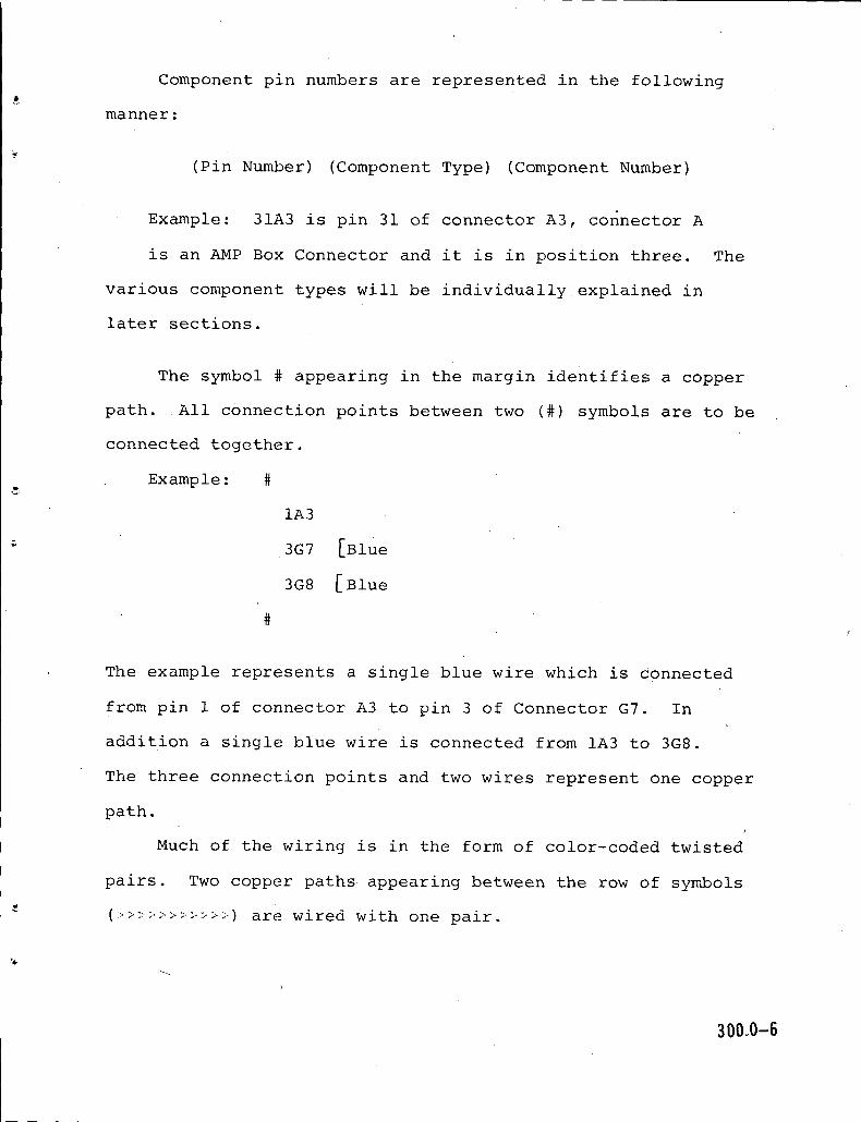
Component pin numbers are represented in the following
manner:
(Pin Number) (Component Type) (Component Number)
Example: 31A3 is pin 31 of connector A3, connector A
is an AMP Box Connector and it is in position three. The
various component types will be individuallyexplained in
later sections.
The symbol _ appearing in the margin identifies a copper
path. All connection points between two (#) symbols are to be
connected together.
Example: #
lA3
3G7 [BlUe
3G8 [Blue
#f
The example represents a single blue wire which is connected
from pin 1 of connector A3 to pin 3 of Connector G7. In
addition a single blue wire is connected from lA3 to 3G8.
The three connection points and two wires represent one copper
path.!
Much of the wiring is in the form of color-coded twisted
pairs. Two copper paths appearing between the row of symbols
(_>>>>>>>>>>_) are wired with one pair.
%
3000-6

Example:
>>>>>>>>>>>>>>>>
#
3A3
24D1 _range
#
4A3
23D1 [Red
#
>>>>>>>>>>>>>>>_>
~This example directs the use of an orange-red twisted
pair (see CAS-5) . The orange wire connects pin 3 of connector
A3 to pin 24 of connector D1. The red wire is similarly routed
from 4A3 to 23D1. Two copper paths have been connected by
one twisted pair.
Succeeding sections of this specification will describe
the individual components to be interconnected.
IV. Wire Preparation
Two types of wire are used in the wiring subassembly.
The first type is a single conductor #30 AWG K_nar insulated
wirewrap wire (Brand Rex T-360) . This wire will be crimped
and soldered and is used in three colors: Red, Blue and
Yellow.
The second type of wire is a twisted pair of two #30
_ AWG Polyethylene insulated wires which is _sed in 17 color
300,0-7

combinations. This wire was made by Brand Rex and is described
in CSL document CAS-5.
All wires used in the wiring subassembly shall be 6.500
i .250 inches long before stripping and termination. The
stripping dimensions for any given wire or pair are given for
each individual type of termination in later sections of this
document.
All wires shall be stripped with an automatic mechanical
stripper. The stripped wire shall be smooth, straight, and free
from nicks, scratches or mechanical deformation.
It is important that the twisted pairs remain twisted with
the original lay length. For the long lay pairs such asa
(Yellow-Slate) it is permissible to give the ends of the pair
an extra twistto prevent unravelling.
V. Resistors
Resistors are considered to have two leads, and a unique
number is assigned to each lead. The resistors are numbered
as follows:
Example:1R601
2R601
1. First numeral -- indicates lead one or lead two
of one resistor.
2. Letter R indicates that component is a
resistor.
%
3. Single numeral (6) -- Indicate type of resistor.
(6) represents a 130 ohm 1/8 watt 5% carbon
composition resistor. 380_0-8

4. Two digit number (01) -- Sequence number of component,
may run from 01 to 99.
The following sequence from'a wiring/list will serve as
an example:
>>>>>>>>>>>>>>>>
1D1 Red
1R601%
#
2D1 Slate
2R601
#
>>>>>>>>>>>>>>>>
This directs that the first 130 ohm resistor (R601) be
connected from pin 1 of connector D1 to pin 2 of connector D1.
The color code may be ignored, and teflon sleeving shall be
used to insulate the exposed leads.
!
VI. Rear Connectors
The components designated by an A on the wiring lists
(A3, A4) are AMP 750 SERIES BOX CONTACT CONNECTORS, AMP
Catalog 941.
Wires which are terminated to the AMP 3-202844-5 are to be
stripped .125 ± .031 inches. The bare end of the wire is to
be fed into the terminal tail and bent over 180 ° with the
% insulation resting in the U shape of the terminal. The wire is
to be soldered, and no solder shall wick into the contact.
300.0-9

The solder meniscus shall not extend past the square perforation
nearest the connector body. The solder joint shall be visually
inspected before the following step is executed.
The joint shall be cleaned and covered by a tight fitting
peice of polyolefin shrink tubing. The shrink tubing shall be
.300 to .350 inches long.
The pin numbering stencilled on the connector block must
be IGNORED. The pin numbers are defined on Drawing 300.0-15.
VII. ASTRO 348 Connectors
The connectors identified with a D on the wiring lists
are members of the Amphenol ASTRO-348 family. The 14-37
configuration shown in this document is a special version with/
some of the environmental sealing parts left out. In the
future, a standard version of this connector will probably
be used, so the differences are noted here toavoid obsoles-
cence of the documentation. The standard bulkhead connector
!
has th e part number 348-40E14-37P1.
The standard connector can be installed by following the
instructions in the Amphenol ASTRO-348 Technical Manual. The
special connector documented here [Amphenol ASTRO 348-20E14-
37P1 (201) Mod.] has a clear chromate finish instead of the
standard olive drab. The modified connector has an unswaged
rear nut and contact retention disk, so all parts are handled
] F ! 0256 ] 2-22-721'_/_'-/_Ip ......... _ ............ ! ...................... ,..4/--_.__.. I
I.....l..............i I { soo.o-n! ' i............ ! ...................... I .............. {.............!i i'k!.i.ffZii2E_J.2Z.i.]
separately as shown later in document 300.0. The modified I
connector does not have the silicone rubber insert in the
rear nut, so the pin numbers must be read from the front.
I
The modified connector shall be assembled in the following
sequence:
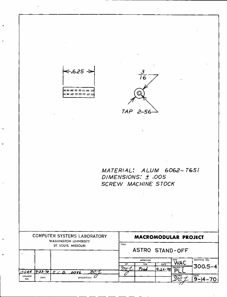
1. Mount the receptacle shell on the faceplate with thestandoffs (Dwg. 300.5-4) and fillister head 2-56 screws.
2. Crimp the contacts per instructions given below, and
insert the contacts into the contact retention disc,
using a simple holding fixture to Support the disc.
3. Apply an interfacial seal, insert the disc assembly
into the receptacle shell, and hand tighten the rear
nut. A picture on a later page identifies the indi-vidual parts.
Wires for these connectQrs shall be stripped 0.125--0.150
inches. The tight stripping tolerance is necessary to insure
that the insulation will tuck into the rear sleeve of the
contact for mechanical support. The wires are crimped into
the ASTRO-348 contacts using a Buchanan No. 612596 hand tool with contact
locator Buchanan No. 613381. Equivalent automatic tooling is preferable.
Crimp settings of (2) have proved satisfactory with two hand
tools, but tool variability requires that some tests be made
before a production setting is adopted. The test criterion is
that the crimped joint shall have 70% of the tensile strength
of the wire being crimped.
The yellow wire to pin 5 of the D connectors and the green
wire to pin 29 may be combined into a yellow-green twisted pair.
If this is not done a single blue wire should be used on pin 29.
0256 2-22-72 300.0-110277 _2--_- 7¥_
I
...........

VIII. Amp Coaxicon Connectors
The connectors identified by a G in the wiring list are
versions of the Amp Twin Standard Coaxicon. The pins are
1, 2, and 3 as follows:
Pin 1 Opposite Small Port - I on Plastic Insert
Pin 2 Opposite Large Port - II on Plastic Insert
Pin 3 Wire inserted under shield ferrule
All wires for this connector are stripped 0.250 inches
± .031 inches. The wires are crimped using Amp crimp die
69231-2 in hand tool 45707-2 or pneumatic tool 69365-2. The
wires must be carefully held during the crimp cycle to prevent
slippage. These connectors are press fit with an arbor press
after crimping.
The orientation of these connectors is important, and is
noted on each faceplate, see 301-9 for example.
IX. Code Switches
The Honeywell Microswitches (indicated by an S in the
wiring lists) are wired with single Kynar-insulated wires which
are stripped 0.250 ± .031 inches. The wires are wrapped around
the turret terminals of ths switches and soldered. All solder
flux must be removed and this assembly must be handled carefully
to prevent breakage of the fine wires.
The switch orientations and pin numbering are shown in
document 300.7.
I'_._iZi_ _ .<'.0. (3/,l'i{ ,, !";'.
-_'49 1-25-72 _e_!";_I
t ....................
I300.0-_

X. Electrical Testing
After the wiring subassembly has been fully assembled into
? the metal shell, suitable adapting connectors shall be mated
with the appropriate front and rear connectors of the faceplate
box and the following electrical tests shall be performed.
1. Continuity:
All copper paths called out on the wiring/list for the
type under test shall be verified to have a resistance of
less than one-half ohm.f
2. Shorts:
Each copper path shall be isolated from all other copper
path s by a resistance greater than one megohm. Ground
wires are an exception to this requirement since they are
not grouped into an explicit copper path. Therefore, all
wires to pin 3 of the AMP Coaxicon, and the 6 inch wires
with ground lugs will be common to each other and the metal
shell.
{ c 'ol3G ,2-2 -7o_ -_ _ (_.. 300.0-1-3
?....................... i............... *f......
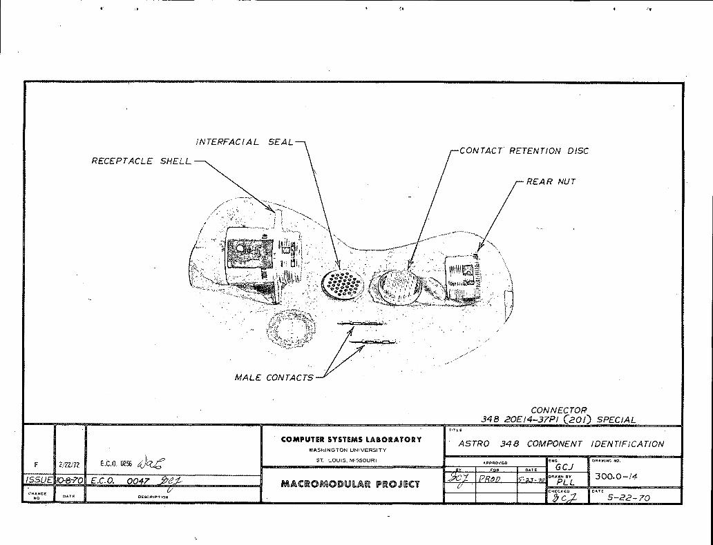
INTERFACIAL SEALFT' RETENTION DISC
RECEPTACLE SHELL, ._..:. / REAR NUT
MALE N C
CONNECTOR
348 20EI4-37PI _201_ SPECIAL' TITLE
COMPUTER SYSTEMS LABORATORY ASTRO 348 COMPONENT IDENTIFICATIONWASHINGTON UNIVERSITY
F 2./2Z/72' E.C.0.0256 ST.LOUIS,M'SSOU_" il "',' '"'"_"o0"''° O,,T,_ GCJ i
j_, =...... i 3OO. O-/4.iSSU E {0.,.8-?0 _E.C,O. 0047 _¢_¢- ......... MAC_OMODU[A_ PROSECT i _- I'.PR,cp _-7¢ PLL. =1
[ - _ i _-HECKED DATE' CHANGE ]NO . j," ........ :..... I Ji '_'C 5-22- 70
iii, ...... , i I I i II Ii
PIN 89 >.- -'< PIN IP/N -< PI N 2r
'< I
A4 --< ' 2
-<- ,A1 -
..... i, _- iii .
!l.....COMPUTER SYSTEMS LABORATORY I " REARCONNECTORORiENTATIO_ANDFiN NUM_,£RING
WASHINGTON UNIVERSITY
ST. LOUIS, MISSOURI ! ...... 7 .... :_ A _OVE Bi I _ E g_'_ I .... _ D_ W_ _ _Om I I '
.......... _ ._ _ _ L_ffi_ ' _ ....... Il I _00. O-- /S
O_TE:
C_Ii,_2.*E DATE I ........... I ' _CL:,_.--- ' :,1_ ?S

COMPUTERSYSTEMS LABORATORY MACROMODULAR PROJECTWASHINGTON UNIVERSITY
TITLEST LOUIS, MISSOURi
CONTACT INSERTION FIXTUREENG DRAWING NO
A.,Rov,o GCJBY FOR DATE
,_._: ?,_,,p, ,,,_.7-;',_DR_h'b aoo.o-ie.ISSUEIO.8-7C' E,C. O. 0047 ..,,°2_/' ,_'
_.._oE DATE O._,'.T.O.5/ 10-8-70NO
U

COMPUTERSYSTEMSLABORATORY _ 1WASHINGTONUNIVERSITY
·1-CELL FPB SHELL
PAGE TITLE CHANGE
300o1-1 TITLE PAGE H
300.1-2 1'-CELL FPB SHELL PARTS LIST A
300o'1-3ONE CELL FACEPLATE BOX MANUFACTURE AND SPECIFICATIONS
300ol -4
F300ol-5 1-CELL EAR G
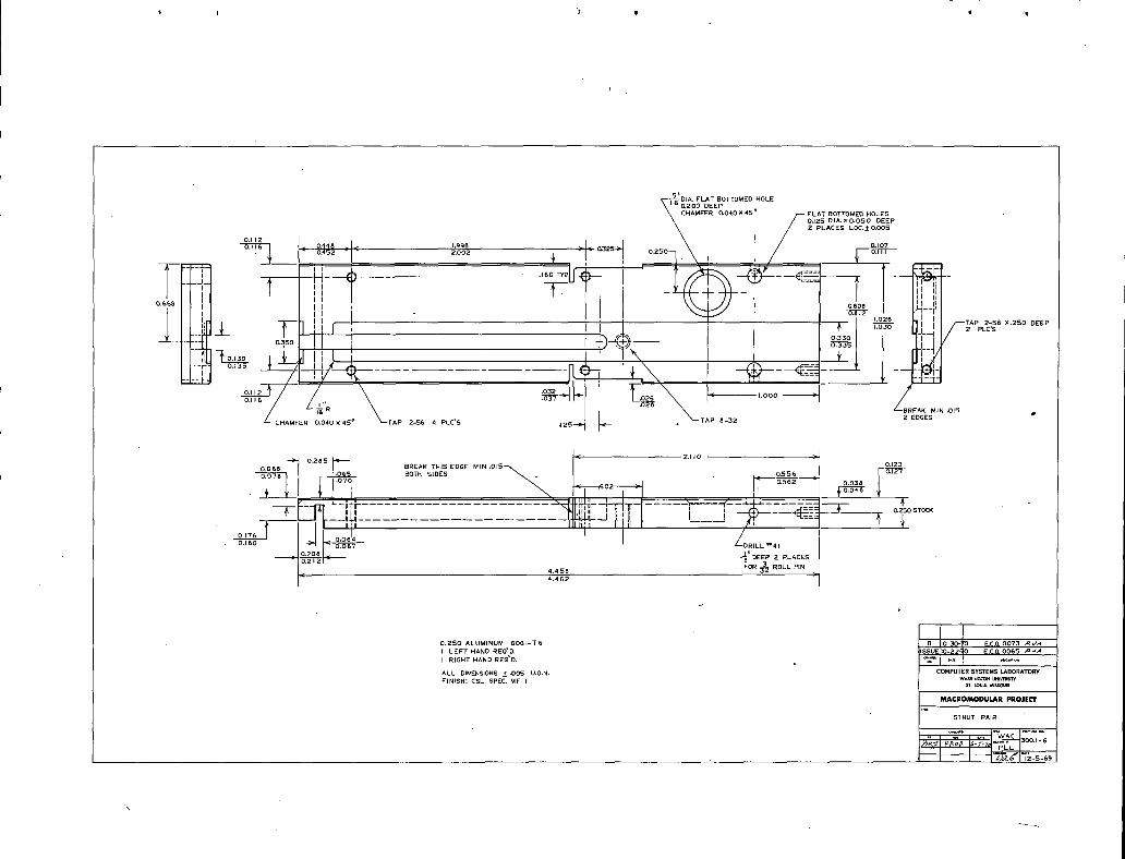
300.1-6 STRUT PAIR B
300,1-7 COVER PLATE PAIR
30001-8 OVERLAY CLIP I'J
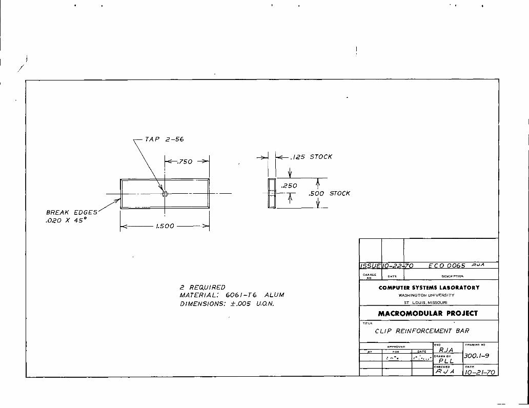
30001-9 CLIP REINFORCEMENT BAR
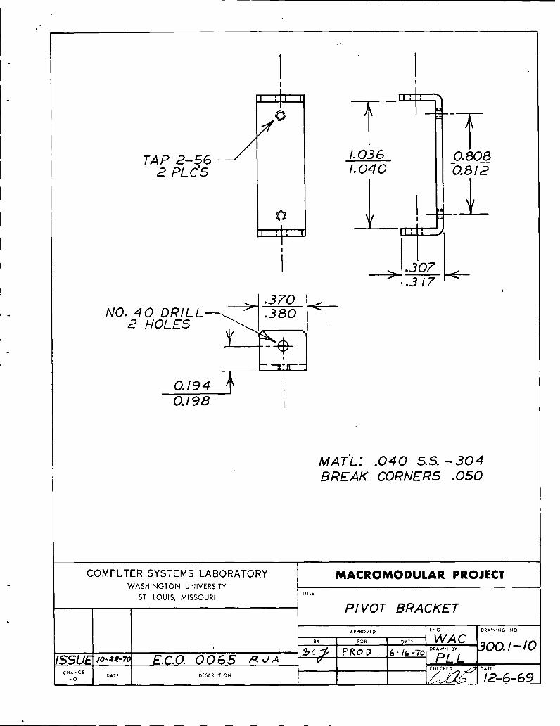
300o1-10 PIVOT BRACKET
300o1-11 RAIL SLIDE D
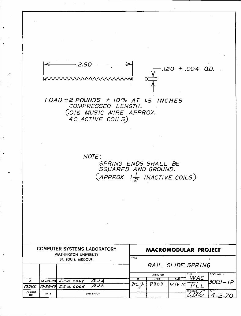
300o1-12 RAIL SLIDE SPRING A
300.1-13 EAR SPRING Ao E
300o1-14 STRUT PAIR SUBASSEMBLY F
300o1-15 ASSEMBLY_iNSPECTION DRAWING OVERLAY CLIP BEND AT ASSEMBLY
300o1-16 ASSE._JBLYHNSPECTION DWG? EAR AND SHIM REPLACEMENT
300o1-17 ASSEMBLY*INSPECTION DWG, OVERLAY CLIP ASSEMBLY
300o1-18 ASSEMBLY-INSPECTION DWG_ STRUT AND COVER PLATE ASSEMBLY C
300o1-19 1-CELL FPB SHELL ASSEMBLY G
IF
i
CHG. E.C.O. DATE APPR CHG E.C.O. DATE APPR j CHG. E.C.O. DATE I APPR.
!ISSUE 0065 10-23-70 Y_ _-J/J E 0163 3-16-71 ,,/--__/-_
A 0069 10-26-70 ._. ;_J,._J F 0236 12-11-71 r 2_
B 0073 10-30-70 _ k//_ O 0239 12-21-71 ,/_&,/_
C 0084 11-18-70 ,_,,J A H o_e,.,q 1-/,_-7.._ ,_kyl,,_ i
D 0145 1-7-71 Y(_ _'w_
MACROMODULAR SYSTEMS PROJECT
300.i-5

J
_' , 1-CELLFPS SHELL
PARTSLIST
QTY. C.S.L.DOC. PART
2 -- VLIER _NS-51N SPRINGPLUNGER
4 -- 3'32 X 1:4 CADMIUM PLATED ROLL PIN
14 -- 2-56 X 1 4 FLATHEAD SOCKET CAP SS SCREW
2 300.1-5 I CELL EAR
1 300.1-6 STRUT PAIR
1 300.1-7 COVER PLATE PAIR
2 300.1-8 OVERLAY CLIP
2 300.1-9 CLIP REINFORCEMENT BAR
2 300.1-10 PIVOT BRACKET
2 300.1-11 RAIL SLIDE
2 300.1-12 RAIL SLIDE SPRING
2 300.1-13 EAR SPRING
CHG. E.C.O. DATE APPR. CHG. E.C.O DATE APPR. CHG. E.C.O DATE APPR.
ISSUE 0065 10-23-70 _JA
A 0067 10 -26 -70 /_:__/'t,_J
i iMACROMODULAR SYSTEMS PROJECT
300.].--2
i
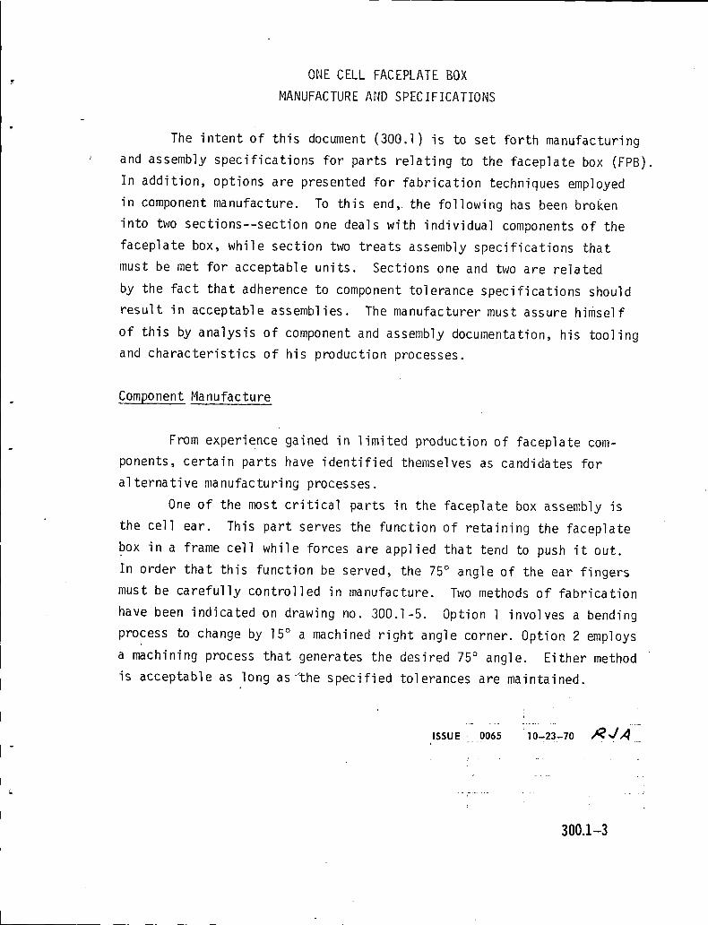
ONE CELL FACEPLATE BOX
MANUFACTURE AND SPECIFICATIONS
The intent of this document (300.1) is to set forth manufacturing
' and assembly specifications for parts relating to the faceplate box (FPB).
In addition, options are presented for fabrication techniques employed
in component manufacture. To this end, the following has been broken
into two sections--section one deals with individual components of the
faceplate box, while section two treats assembly specifications that
must be met for acceptable units. Sections one and two are related
by the fact that adherence to component tolerance specifications should
result in acceptable assemblies. The manufacturer must assure himself
of this by analysis of component and assembly documentation, his tooling
and characteristics of his production processes.
.ComponentManufacture
From experience gained in limited production of faceplate com-
ponents, certain parts have identified themselves as candidates for
alternative manufacturing processes.
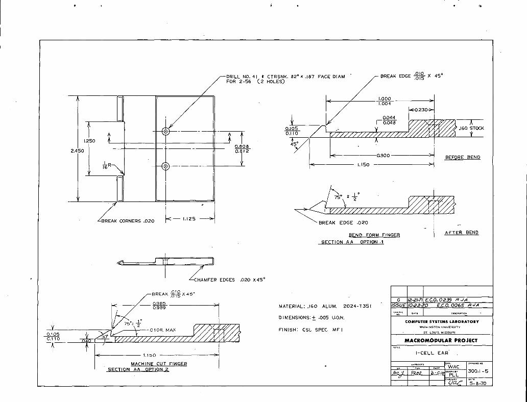
One of the most critical parts in the faceplate box assembly is
the cell ear. This part serves the function of retaining the faceplate
box in a frame cell while forces are applied that tend to push it out.
In order that this function be served, the 75° angle of the ear fingers
must be carefully controlled in manufacture. Two methods of fabrication
have been indicated on drawing no. 300.1-5. Option 1 involves a bending
process to change by 15° a machined right angle corner. Option 2 employs
a machining process that generates the desired 75° angle. Either method
is acceptable as long as'the specified tolerances are maintained.
300.1-3

Drawing no. 300.1-7 is the cover plate pair. These covers are
' formed from .090 thick aluminum stock. The 90° angles at the corners
indicate zero radius bends. This restriction may be relaxed somewhat
as long as this corner does not interfere with the .015 break on the strut
pair corners (drawing no. 300.1-6). In addition, the countersink for
the 2-56 flat head screws on the covers must be deep enough to com-
pletely recess the heads if the outside bend radius is increased.
Assembly Specifications
Drawings 300.1-15, 300.1-16, 300.1-17, and 300.1-18 are various
views of assembled faceplate box components. These drawings indicate
maximum and minimum finished dimensions as well as assembly techniques to
be applied in manufacture.
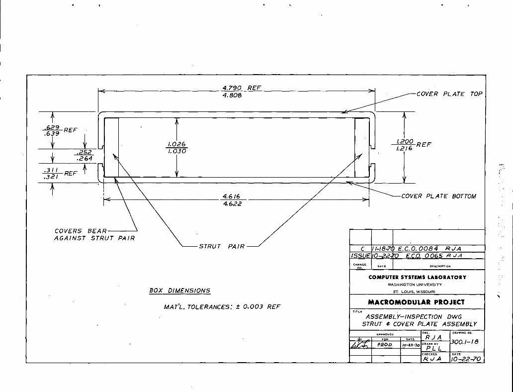
Drawing 300.1-18 is the rear view of the strut pair and cover
plate pair assembled. The slot width formed by the space between upper
and lower covers should be inspected at the connector end of the box
due to the fact that this slot tapers somewhat toward the overlay clip
which is retained by the covers.
A section through the front of a complete box appears in drawing
300.1-17. This drawing indicates assembled dimensions of the overlay
clip with respect to the strut end..
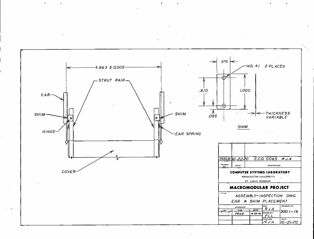
The ear placement on the.finished box is critical to the proper
functioning of the box. It is therefore necessary to insure finished
ear placement dimensions and tolerance. Drawing 300.1-16 shows the
required spacing between ears on a completed box. This dimension may
be controlled by the addition of brass shims between the pivot bracket
and ear. Shim size is indicated on this same drawing.
...................... [RJ _.!ssuE ! 0065 _10-23-70
:.... i ...... ¢- ........... .................
i
300.1--4
X 45*
/_DRILL NO. 41 t CTRSNK. 82'x .187 F'ACE DIAM /-- BREAK EDGE i'_"_'
FOR 2-56 (.2 HOLES) _ '
< I.O04 0.230 ,_J71
0.044 - {
_' _IY [- o.--b-_- V///_j////I ,[
I o.,o5 / ) -- _ K////X//////F .,6oSTOCK,,_o _ -_' _ o,-_ / r//////////?///////////////////_ *2.450 --' -- O. 12
900,< . -I BEFORE BEND
/'_?so + I_L°
CORNERS ,020 _ 1.125 > XBREAK EDGE 020 _
BEND FORM FINGER AFTER BEND
SECTION AA OPTION .1
FER EDGES .020 X45 °
.010 ....
--BREAK .O'"I'S'z, 4:::, G i,P.-ZI-?I E.C.0.02,.,_9 /:_../A/ 0.985
_/ 0.989 _ MATERIAL: .160 ALUM. 2024-T351 ISSUE' 10._2-;'0 E.C.O. 0065 ,qv,4C.A_?E U*TE DESC,mT,O.
DIMENSIONS:+ .005 U.O.N,
010R MAX FINISH: CSL SPEC. MFI WASHINGTONUNIVERSITY
.040 MACROMODULAR PROJECT
{ { . , .....-_ 1.150 -- _ i-CELL EAR'
/
MACHINE CUT FINGER { , ,....... I,.;VAc ..........' SECTION AA OPTION 2 -- :_ '_
I_, ¥--7_ r..=...: 300. i - 5?f_oP
_IDIA. FLAT BOTTOMED HOLES 0.200 DEEP
. . .
77 ' ',' Ji____ .... .,SOTY..h.,._,_* f _ -_,f----_--= ---'_.4--t :T -rr - ,,,
o._,_,s [ I m, m : i I _x I // ' ' ,'_--_l'!ii!1
x__ I i o.e,oe j__
, . _ o.-_I I , _ I r( I I_ - TAP 2-56 X.250 DEEPl, j_ wh, r , , j _ , , + I ,._ IL_il/-2 PL¢'Bo.JBoI' I r , , _-,,_,_ I I , o._:,oI 1-i--I,I/, / [ [ i m _,/ ,L.4.// i O.'"_3-s J[ !/,/
T:.::: .,....L._!l _ i j r _x m , , I ]-.,'-71· ' ' ','/-¢_-.......... g_,' '+.X f -G---_:_---_ ---_-II ', Y , , , , ,,, / -_-_-I0.112 '_ .032 · I 000 ·.....//.. \ .o_4P-II'[Ls_ I · /
/ CHAMFER 0.040 X 45 ° _'--TAP 2-56 4 PLC'S .125--_"_ _ * TAP 8-32 2 EDGES
MIN .015 0.123
.070 ' ' < ¢56Z · 0.038
_lr, ill I I: , ii I ____._$=-___.._;? O,ESOSTOCK
--[_-'_,-_-J _ _ L____J _y, '_==9 _' J,.._.,J I-----I_-I---ilmll', i; ii , /" m TI i I'lm
o,.l_ _ _<§:§,_1.I i I --/DB,LL'4,t.._- ¥'_EE,_.,.AEES '4 4 BB . FOR 3_ ROLL PIN
· 4 462 ·
IL0,250 ALUMINUM-SOSI-TG B 0-30- E.C,O, OOT3 ._'...'.4
I LEFT HAND REQ_D. SSUE_IO-_Z-'_'O E.QO. OOGS _.4
,B,GHT,A,D'_E_'O. _ I "" I ---ALLDIk_E_ISIONS _' .005 U.O.N. COMPLri'ER SYSTEMS LABOEATORYFINISH: CSL SPEC. MD I WA_IIN_TO¢IUNI_RSlW
s_. i.oums._ssoul_l
MACROMODULAR PROJECT
ST_UT PAIB
_ w_c _oo.,-s_;_ _ I,:-_-,_PLL
\

J BREAK EDGE 0.0)5 MIN2.309 >
/ .250 ,.
!ILL _, CTRSNK..187 FACE DIAM.FOR NO, Z-56 C5 PLACES)
BREAK
BREAK EDGE
CHAMFER .050 X45 ° THIS END ONLY
I 4,616 _J'( 4.6Z2 _ J
I 0.090 ALUMINUM- 3003-HI4
A BOTTOMPLATE REQ'D,
;'l .... J
J ISSUElO-22n'O E.CO. 0065 _t,/.40.015
°"'-_-_'_ '1' o.,,4 c_' I _,?.........T 0 P BOT TOM COMPUTER SYSTEMS LABORATORY
WASHINGTON UNIVERSrI¥0.542 0.224 ST. LOUIS, MISSOURI0.050 A 0._ 0.228
FINISH: CS l SPEC MF I MACROMODULAR PROJECT
iTMI COVER PLATE PAIR
Af_OVlED I ENO D_WING IlO,
........ Iwaci_ pR,P &-P';_ PLL 300.1-7'
' i ....I 12-5 -69

262 OO5o2 47 5
BREAK I !0 0'i55'__ I_. _lEDGES < I- 4.605 -I
< 2.360 > < 0.,90
0.210
L Looo >l[- f
0.030 ALUMINUM -3003- hl4AlL DIMENSIONS __.005 U.O.N.FINISH: CSL SPEC MF1
2.302
I
/_ I_ H 1-12-T.: E.C.O. 0283 /_/A I
i ISSUE 10-22-7) E.C.O.0065 _ ,./,4CH&HOE DATE DESCIIF'TIOHHO.
/___ II CO.""TE.SYSTEMS_.O.^TO.Y
· WASHINGTON UNIVERSITYST. LOUIS, MISSOURI
I_I_CROMODULAR PROJEL'_F
DRILL NO. 4 I Tm.OVERLAY CLIP
^pPIm_D ENO OI_WtNO HO.
_.. WACbY DAT_
_c:_ p/_. _-_-7_°__'__3oo.i.8u
! m !w $
//
- TA P 2-56
.500 STOCK
BREAK EDGES '/'''_ _l
.020 X 45*-" 1500 "-
ISSUE10-22-70 E C O 0065 ,_v.4CHANGE
NO DATE OESCR_PT_Ot4
2 REQ. UIRED COMPUTER SYSTEMS LABORATORYMATERIAL: 6061-T6 ALUM WASHINGTONUNIVERSITYDIMENSIONS: -+,005 U.O.N. ST LOUIS, MISSOURI
MACROMODULAR PROJECTTITLE
CLIP REINFORCEMENT BAP
APPROVED ENG DRAWING NO
.... RJADATE
,, ....... 300. I-9;"'* ' '""' PLL
CHECKED DAT E
_ d ,,4 10-21-70
.' I
I II I
I ; I; II I I: I _
TAP 2-56 / 1.036 0.8082 PLC'S 1,040 0.812
i
I
[ :Il ! I'11_ ; _,II
] _ .307_- .317
__ .370 jNO. 40 DRILL f .380 -_
2 HOLES _'_ %' 1
I
0.194 _ I,0.198 I
MAT'L: .040 5.5. -304BREAK CORNERS .050
COMPUTER SYSTEMS LABORATORY MACROMODULAR PROJECTWASHINGTON UNIVERSITY
TITLEST LOUIS, MISSOURI
PI VOT BRACKET
APPEOVED ENG DRAWING NO
WACB"r I FOR DATE
, D.AW.., 300. I- I0ISSUE _J°''';_'?° E.C.O. 0065 _qu_ _c_. ?t_oo '6.zt,-,o PI,.LI
, CHECKED _ DATE
CHANGE DATE DESCRIPTION /_ /2--6--69n_O i

_f_.__ 3.390 --)
3.395 _10.055
0.065 _
0.325
0.330_----_---0.120
0.125 BRE AK .050_4 CORNERS
._._ w D I-0-7 E.CO. 0145 _ ,./.4
-_ ' GL ISSUE 10-2 0 E.C.0.O065 ,_ ,/,40.165 MAT'L; I .o. I '_ / ...........
0.040 S.S.- 304 BREAK THIS ED COMPUTERSYSTEMSLABORATORY.020 MINX 45 ° WASHINGTONUNIVERSITY
ST. LOUIS, MISSOURI
MACROMODULAR PROJECTTIT'..E
RAIL SLIDE
APPROVEO IENG. DRAWZKG NO.
"i -' ' .... '"""c I%I _._e_ P/_p I_;-r-7ol°""_","',, . I-I I
_ 112-6-69
I
I
'_ 2.50 .--
._F.120 _+ .004 O.D.0 _
LOAD =2 POUNDS _+ 10°7o AT I.S INCHESCOMPRESSED LENGTH.
(.016 MUSIC WIRE-APPROX.40 ACTIVE COILS)
NOTE:SPRING ENDS SHALL BES(2UARED AND GROUND,
- I(APPROX I_, INACTIVE COILS)
COMPUTER SYSTEMS LABORATORY MACROMODULAR PROJECTWASHINGTON UNIVERSITY
ST. LOUIS, MISSOURI T,TLE ,
RA/L 5L/DE SPR/NG:
APPROVED ENG DRAWING '_'
- , O,,E WAC,4 Io-,?.4-7o E',C.O. 00_7 ,,_,.JA .FOR 3001-12
15sue /o-az.7o _.c.o. oo_$ ,,_u_ .._c"_,d PROP G-/6-;'¢ _RA/5"_'LCHECKLD _ P,,,"
c.A.OE 4- -7oI NO. DATE DESCRIPTION
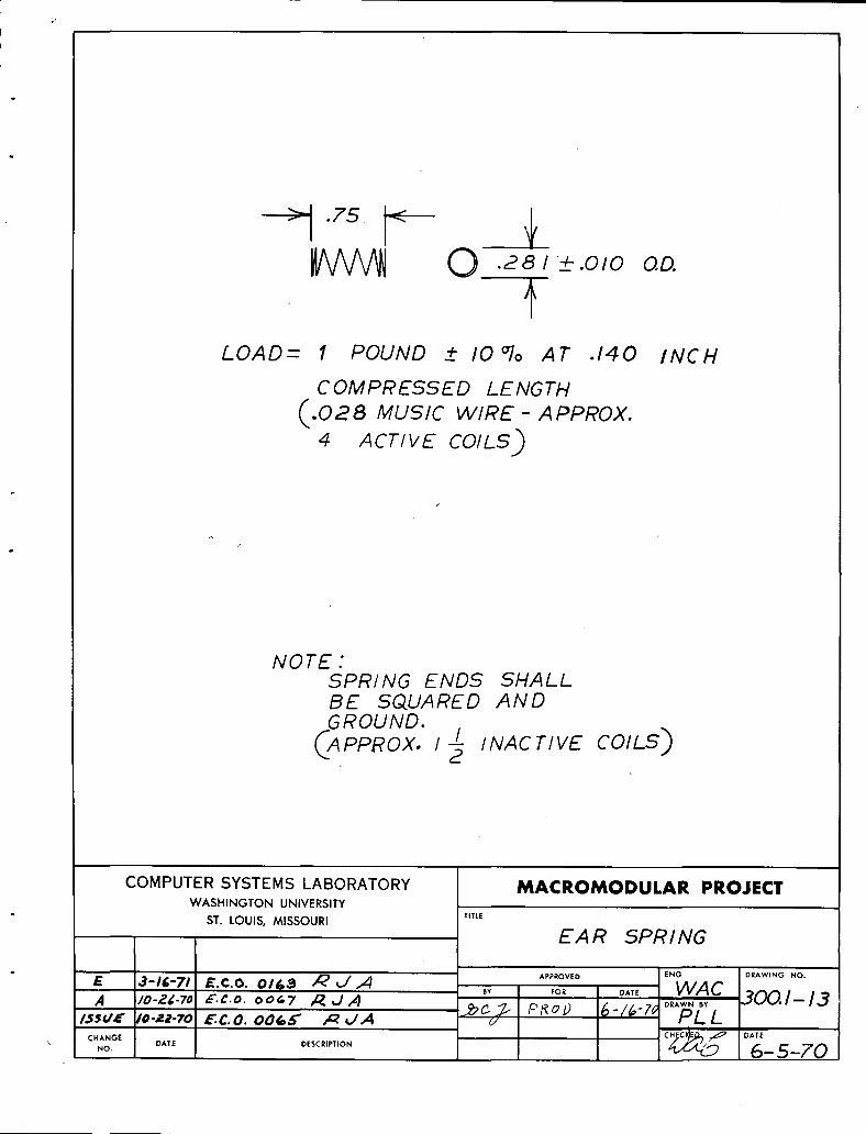
75-0 _8,__o,ooo
LOAD- I POUND !- 10o70 AT .140 INCH
COMPRESSED LENGTH
.028 MUSIC WIRE- APPROX,
4 ACTIVE COILS)
NOTE:SPRING ENDS SHALLBE SQUARED ANDGROUND.
I COILS)(APPROX./_ INACtiVE
COMPUTER SYSTEMS LABORATORY MACROMODULAR PROJECTWASHINGTON UNIVERSITY
ST. LOUIS, MISSOURI TITLE
EAR SPRING
E 3-1_-71 £.c.o. 0/63 R J ,,4 ,Y A,,,ovED EHO D,^W,NOHO.A /o-z4;-ToE.e.o.ooa7 /ZUA ,o. oA,E WAC 300.1-13
i.ssua' /,._.a.7o_.c.o.oo_.[ ,,_uA .._c._ p_c,/) 6-/_-z_ D"'_" L(-/
CHANGE CHiC E_ ,,_ DATE
' Ho 0,TE _ESC,,,,OH _ 6-5-70

STRUT PAIRNO. 300. I-6
PLUNGER
¢ t:9 ! _'-- i ,4 -,_ ;
! : I :i_ r_
· ·
ROLL PIN _ E::,, -_,= .,_. ._ ........., ..... ",
/- PIVOT BRACKET · G ' ' :SL.';NO. 300.1-10 N0.300.'-13 NO. 300.1-11
SPRING PLUNGERINSTALLATION
,, , I
ITITLE
COMPUTERSYSTEMSLABORATORY STRUT PAIR SUBASSEMBLY 'WASHINGTON UNIVERSITY
I
ST, LOUIS, MISSOURI APP.OVEO ENG. DRAWINGNO.
F t2-14.71 E.CO. 0236 ?1 _/ ..... o^,_ WA C_C_¢ PR_D, ;-r-?_ ....... 300.1-14
ISSUE 10-22 70 E.C.O. 0065 ,,_,./A MACROMODULAR PROJECT _ PLLCHANGE
i NO, DATE j o_sc ....... i 6--5'-70

'_ BEND MINIMUM S* AFTERASSEMBLY OF OVERLAY CLIPS5 ° MIN.
CLIP REINFORCEMENTBA RS
· I -_ I . '
" OVERLA I CLIPS
_/ '-ISSUE10.22 0 E.C.O. 0065 ,_ ,.t,,4
S TRU T c..... D._.o. I / ...........COMPUTER SYSTEMS LABORATORY
WASHINGTON UNIVERSITY
ST. LOUIS, MISSOURI
MACROMODULAR PROJECT
TITL_
ASSEMBLY- INSPECTION D WG.OVERLAY CLIP BEND AT ASSEMBLY
· DRAWING NO......... m....I
A' D. 300. I- 15
/.::.'I P.oo '°-'"° ^,_L b II
IJ 4.863 -+0.005 -_1 _ 3 '$
- 1_' _ _-~o. _l _PLA_ES7--
.819. /.oooEAR
¢ .>SHIM _ SHIM _ _ .<----- THICKNESS
__/ .095 ' VARIABLE
ISHIM
/ '1/- ISSUE 10-22 E. CO 0065 /_ ,/,4
CHANGE DATE
.o. I / ...........COVER COMPUTER SYSTEMS LABORATORY
WASHINGTON UNIVERSITY
ST LOUIS, MISSOURI
MACROMODULAR PROJECTTITLE
ASSEMBLY- INSPECTION DWG.
EAR _ SHIM PLACEMENT
.Y , A.;;;VED°ATE_"_ 300.1--16D

OVERLAY CLIP--_
.105
.125
.240
.260 I- i
la
? .
_ ' CLi/PREINFORCEMENTBARSTRUT ISSUE 10-22-;'0 E,C.Q0065 m,/,a iCHANGE i
NO. DATE DESCRIPTION
COMPUTER SYSTEMS LABORATORYWASHINGTON UNIVERSITY
t
$'_ LOUIS, MISSOURI
MACROMODULAR PROJECTTITLE
ASSEMBLY- INSPECTION DWG. 'OVERLAY CLIP ASSEMBLY
ENG. DRAWINGNO.APPROVED
·Y _9. O^T_ R J A
:..: , ,n:_ 13oo./-/z!. /, (,_ PROO. IO-.Z_-7oDRAWN"V_ - PLLCHECKED DATE
,../.4 I0-22-70
4.790 REF -._l
4.808 - _j_...._covER PLATE TOPs
.629 REF l
.639
_ j 1.026 ,;_/ ' R EF
.252 I.030
.3 / I i:_'' ,o'-327 REF
, ? ....4.616 / COVER PLATE BOTTOM i
622 _I i -
COVERS BEAR _ _
AGAINST STRUT PAIR
STRUT PAIR C 11-18'7() E.C. 0.0084 AdA '.ISSUEIO-22-;'O E.C.O. 0065 A uA
CHANGE DATE DESCRIPTION :NO,
COMPUTER SYSTEMS LABORATORY . ':WASHINGTON UNIVERSITY !
BOX DIMENSIONS ST. LOUIS, MISSOURI i
MAT'L, TOLERANCES: _ 0,003 REF MACROMODULAR PROJECT
.....ASSEMBLY-INSPECTION DWGSTRUT ¢ COVER PLATE ASSEMBLY
ENG. DRAWING NO.APPROVED
4, . ,_..... .......R J A 300.1-18_ _/d_,_' PROO. ,o---7o- PLLCHECKED I DATE
d _ 10-22-70
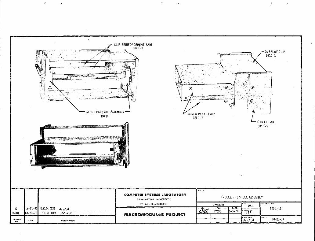
CLIPRENFORCEMENTBARS300.1-9 'CLIP
" 30_33: B
P o COVERPLATEPAIR30{1.14 30{3.1-7
- EAR
_.'_"_" _..... .,,, _'_"_-_-_"_"_'_"_?_;'_"_'_"_'_'_-_"_ 300,]:-5 -
.... ,.... ,_ r,, {i TITHE
COMPUTER SYSTEMS LABORATORY ]:-CELLFPB SHELLASSE).4BLYWASHINGTON UNIVERSITY . ,....... · '
:' ' :"- ' EN_, DRAWI_O NO,
ST, LOUIS, MISSOURI APPROVEO WAC
r m j_ F _ .... _M _ _V m _00_ i_ 1_.-.-.Ec.oo.,_ PRO,,-S-,0 L--v -
........... 0,Zi:70....... /4 ICMANG_[ DATE O{[$(_%PT _ON ..... ""' --
#O, II,I

I
CO JJ_milJ.J'mrIJR S'¥ $1r m_J_ls IIAm OR.J_lr O m_Y [_j_jl=__t,,.,,w v...=lWASHINGTON UNIVERSITY
2-CELL FPB SHELL
PAGE TITLE CHANGE
300,2-1 TITLE PAGE A
300.2-2 2-CELL FPB SHELL PARTS LIST A
300,2-3 TWO CELL FACEPLATE BOX MANUFACTURE AND SPECIFICATIONS300.2 -4
300,2-5 TWO CEiL EAR
300.2-6 TWO HIGH FACEPLATE °
300,2-7 MULTI HEIGHT FACEPLATE BOX WIRING GUARD
300,2-8 2-CELL FPB SHELL ASS EMBLY
o
i
CHG. E,C.O. DATE APPR CHG E.C.O. DATE APPR J CHG. E.C.O. DATE , APPR.
ISSUE - 1-24-72 '_ _'J/J i
A 0260 4-4-72 _ _'.-/',,,_
MACROMODULAR SYSTEM,_PROJECT 300.2-]J

2-CELL FPB SHELL
PARTS LIST
I QTY. C.SoL. DOC. PART)
4 - VLIER #NS-51N SPRINGPLUNGER
8 - 3,,32 x 1/4 CADMIUM PLATED ROLL PIN
28 - 2-56 x lt4 FLATHEAD SOCKET CAP'P'S,S SCREW
2 300.2-5 TWO CELL EAR
1 300.2-6 TWO HIGH FACE PLATE
1 300.2-7 MULTI HEIGHT FACEPLATE BOX WIRING GUARD
2 300.1-6 STRUT PAIR
2 300,1-7 COVER PLATE PA_R
2 300.1-8 OVERLAY CLIP
2 300,1-9 CLIP REINFORCEMENT BAR m
4 300,1-10 PIVOT BRACKET
4 300.1-11 RAIL SLIDE
4 300.1-12 RAIL SLIDE SPRING
4 300.1-13 EAR SPRING
CHG. E.C.O. DATE APPR. J CHG. E.C.O. DATE APPR. CHG. E,C.O. DATE APPR./
ISSUE - 1-24-72 R_._
A 0260 4-4-72 /_ _JA
MACROMODULARSYSTEMSPROJECT 300.2--2

TWO CELL FACEPLATE BOX
MANUFACTURE AND SPECIFICATIONS
The intent of this document (300.2) is to set forthmanufacturing and assembly specifications for parts relatingto the 2-cell faceplate box (FPB). In addition, options arepresented for fabrication techniques employed in componentmanufacture. To this end, the following has been broken intotwo sections--section one deals with individual components ofthe faceplate box, while section two treats assembly specifi-cations that must be met for acceptable units. Sections oneand two are related bythe fact that adherence to componenttolerance specifications should result in acceptable assemblies.The manufacturer must assure himself of this by analysis ofcomponent and assembly documentation, his tooling andcharacteristics of his production processes.
Component Manufacturer
From experience gained in limited production of faceplatecomponents, certain parts have identified themselves as can-didates for alternative manufacturing processes.
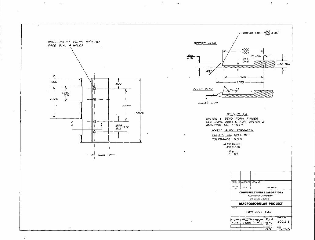
One of the most critical parts zn the faceplate boxassembly is the cell ear. This part serves the function ofretaining the faceplate box in a frame cell while forces areapplied that tend to push it out. In order that this function
' be served, the 75° angle of the ear fingers must be carefullycontrolled in manufacture. Two methods of fabrication have
been indicated on drawing no. 300.1-5. Option 1 involves abending process to change by 15o a machined right angle corner.Option 2 employs a machining process that generates the desired75 ° angle. Either method is acceptable as long as the specifiedtolerances are maintained.
I..................!.........!...................................!........I.......1.................k...............l.......... 300.z-3 '

Drawing no. 300.1-7 is the cover plate pair. Thesecovers are formed from .090 thick aluminum stock. The 90 °
angles at the corners indicate zero radius bends. This res-triction may be relaxed somewhat as long as this corner doesnot interfere with the .015 break on the strut pair corners
' (drawing no. 300.1-6). In addition, the countersink for the2-56 flat head screws on the covers must be deep enough to
completely recess the heads if the outside bend radius isincreased.
Assembly Specifications
Drawings 300.1-15, 300.1-16, 300.1-17, and 300.1-18 arevarious views of assembled fa ceplate box components_ These
drawings indicate maximum and minimum finished dimensions aswell as assembly techniques to be applied in manufacture.
Drawing 300.1-18 is the rear view of a strut pair andcover plate pair assembled. The slot width formed by the spacebetween upper and lower covers should be inspected at theconnector end of the box due to the fact that this slot tapers
somewhat toward the overlay clip which is retained by thecovers.
A partial section through the front of a box appears indrawing 300.1-17. This drawing indicates assembled dimensionsof the overlay clip with respect to the strut end.
The ear placement on the finished box is critical to theproper functioning of the box. It is therefore necessary toinsure finished ear placement dimensions and tolerance.Drawing 300.1-16 shows the required spacing between ears on acompleted box. This dimension may be controlled by theaddition of brass shims between the pivot bracket and ear.Shim size is indicated on this same drawing.
[Cl-_(',..E.C.O. '"' D/,TE .,kPPl_.
I_ - 1o2d_72 ._..?_j' ,,4'
500.2-4
DRILLFAcEDIA.NO'4 14 HOLEsC"SINK82 °x.187 BEFORE BEND _'-/BREAK EDGE _ x
45 °
i_/ l:go°°_>,1,,o} I/ o_._°_.. £;o4__V///////////_.,_O_T_IIIII IIIll/lll
6oo _ * ,_ 9oo.820 J I,150
_._o { BREA_.O_O· .*.970 SECTION A A
OPT/ON I BEND FORM FINGERA SEE DEG. 300.1-5 FOR OPTION 2
.808 MACHINE CUT FINGER.8'--T2 TYPMAT'L: ALUM 2024-T3SI
FINISH: CSL SPEC MF I
TOLERANCE U.O.N.
,C .X X X +.OOS
.XX +-.010
>_ , __x+ /_!_1.12S X -64
I
ISSUE/-20-_ ! R_/A
COMPUTER SYSTEMSLABORATORYWASHINGTON UNIVERSITY
ST. LOUIS, MISSOURI
MACROMODULAR PROJECT
TI_LE
TWO CELL EAR
^.e.ov£D E.G_ O.^WI.G.0.J A
°^*_ o...... 300.2-S·'_,_ PR;D /-,._/.'7,f PLL
12-21-71
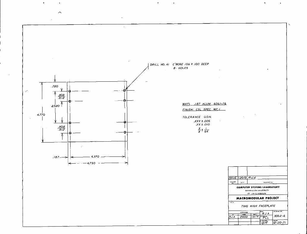
DRILL NO. 41 C'BORE.I56 X.lO0 DEEP
8 HOLES
iiii!c_ ·
MAT'L .187 ALUM 6061-T___
FINISH: CSL SPEC MF
4.770
I _ I TOLERANCE U.O.N.
_1 ___ __ .XXX +-,005.XX +- .010
.808
.81_ _x+ iO-- --O X - 64
< 4.750 ' I
COMPUTlfR SYSTEMS LABORATORYWASHINGTON UNIVERSITY
ST LOUIS, MISSOURI
MACROMODULAR PROJECT
TnLE
TWO HIGH FACEPLATE
'_J; I P_'3o"'*"_°"_t_.z }6c.¢?[ ;_:2o-7,

.. , · .
f1.546
'i°'ti
.030 STK
r 1.5621 _ :.4.605
ISSUE I-£0.F2 A',./.4MAT'/' .030 AlUM 3003-1-114 ......
NO. DATE DESCRIPTION
FINISH: CSI SPEC MF I COMPUTERsYSTEMSLABORATORY·WASHINGTON UNIVERSITY 1;'
v,
TOLERANCE U.O.N. sT LOUlS.M,SSOURI
.XXX " .OOS MACROMODULAR PROJECT.XX_+ .OlO
TITLE
_.X_+ I MULTI HEIGHT FACEPLATEX 64 BOX WIRING GUARD
A.piPROV _ D ENG* DRAWING NO,
· R ../ A !m' ......., 300.2-7
R,3,4 PROD ix-a/- 7,_D._.._. ICHECKED [:)ATE
iiz-zo-zti I

u -..:........... II Ifil I,II
CLIP REINFORCEMENTBARS
300.1-2 OVERLAY CLIP300.1-8
iii'COVERPLATE PAIR
STRUTPAIR SUBASSEMBLY 300.1-7 TWOHIGH FACEPLATE
300.]_-14 TWO 300.2-6300.2-5
, ,, .. ,
i TfTLE
COMPUTER SYSTEMS LABORATORY 2-CELL FPB SHELL ASSEMBLY
WASHINGTON UNIVERSITY
ST LOUIS, MISSOURI AppROVEO INC. RJA ORAWING N_'
.......... "y _. o,.TE 300.2-8
· ._,./,.,4 PROD. /',3/-72 o.^.._p:ISSUE ...... 1':24-72 ' ___,,4_ _,............... JiI _CRO_O OU L_ _ PROJEC T
....... _",W' q-NO. O_,t_: OESCRt_T_ON L,_
COMPUTER SYSTEMS LABORATORY 3_0---_WASHINGTONUNIVERSITY
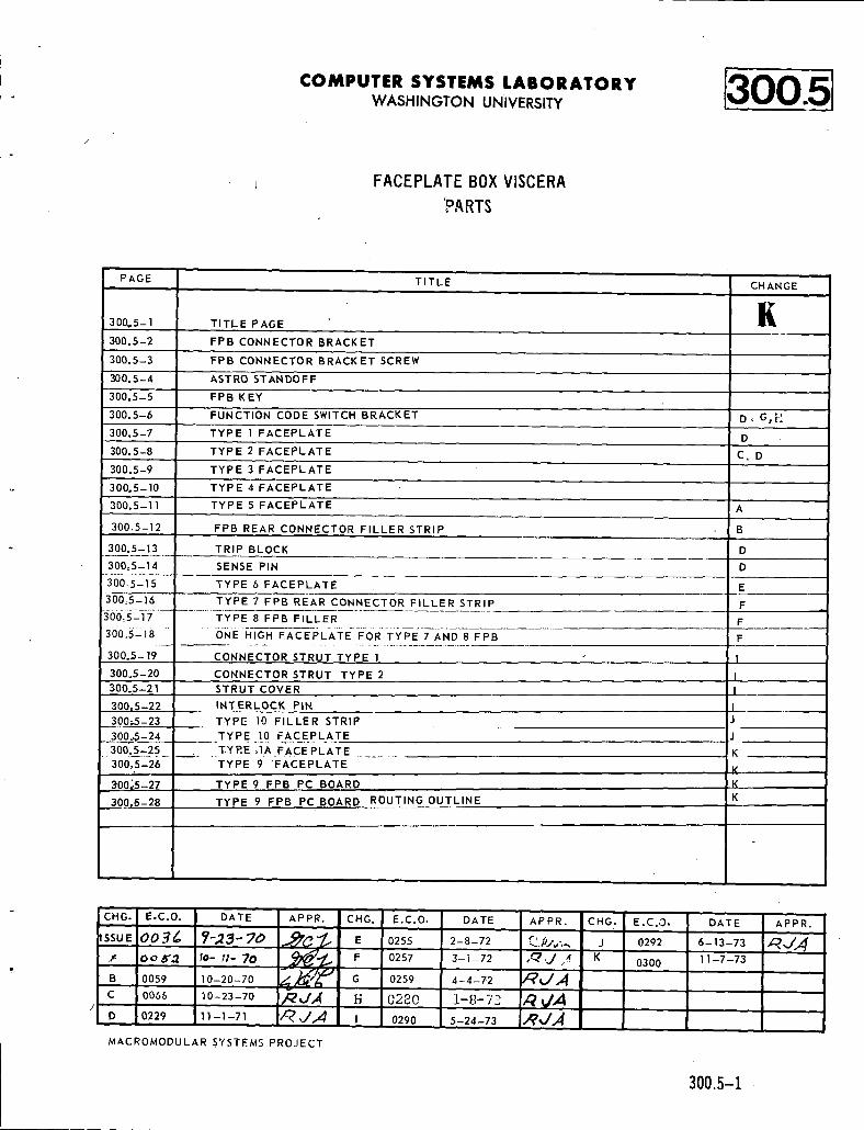
j FACEPLATE BOX VISCERA
'PARTS
PAGE TITLE CHANGE
300,5-1 TITLE PAGE E
300.5-2 FPB CONNECTOR BRACKET
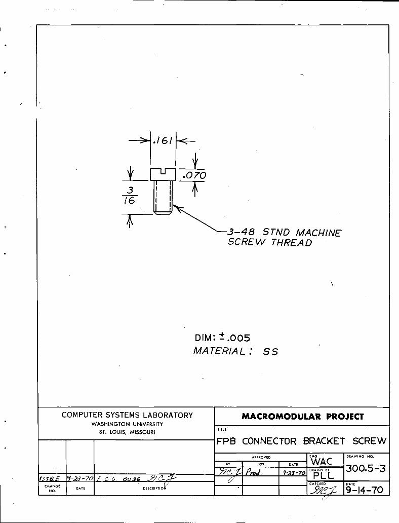
300.5-3 FPB CONNECTOR BRACKET SCREW
300.5-4 ASTRO STANDOFF
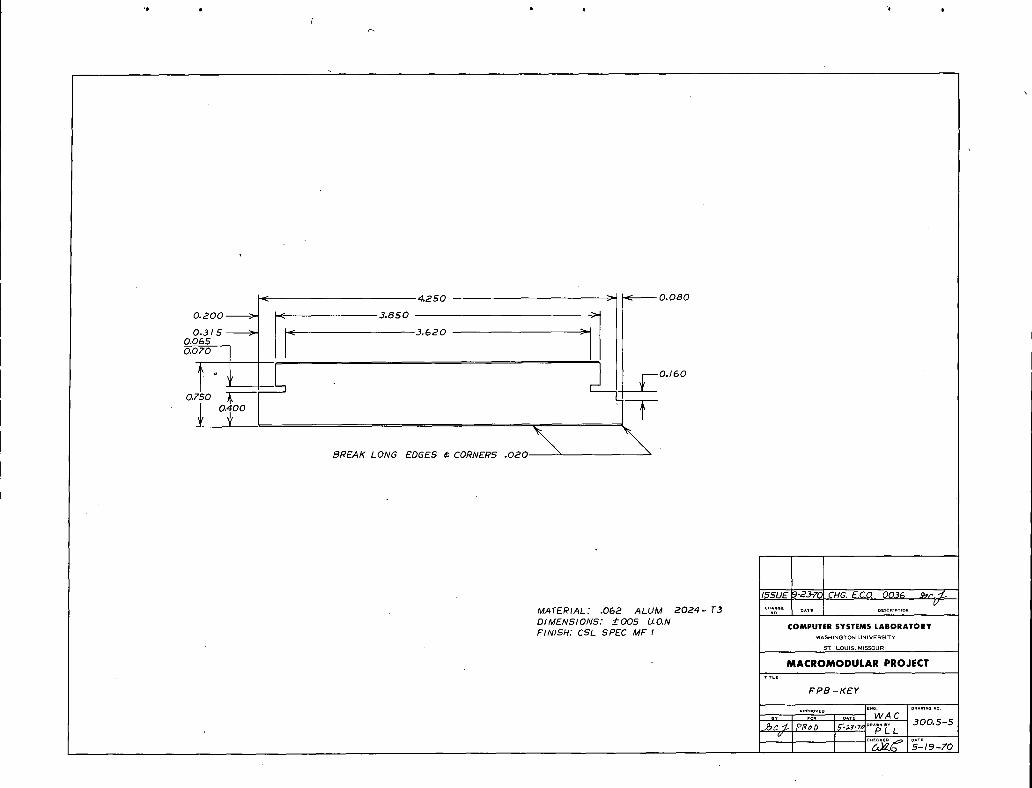
300.5-5 FPB'KEY
300.5-6 I=UNCTION CODE SWITCH BRACKET JD., G,_!
300.5-7 TYPE 1 FACEPLATE D
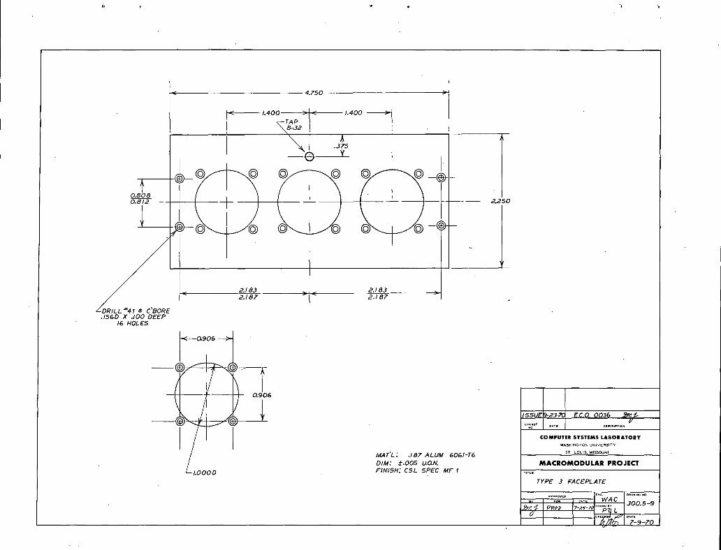
300.5-8 TYPE 2 FACEPLATE Co D300.5-9 TYPE 3 FACEPLATE
300.5-10 TYPE 4 FACEPLATE
300.5-11 I TYPE 5 FACEPLATE A
300_5-12 FPB REAR CONNECTOR FILLER STRIP , i B
300.5-13 TRIP BLOCK i D
300o5-14 SENSE PIN D
300_5-15 TYPE 6 FACEPLATE E
300_5-16 TYPE 7 F'I_B REAR CONNECTOR FILLER STRIP F
300=5-17 , TYPE 8 FPB FILLER F
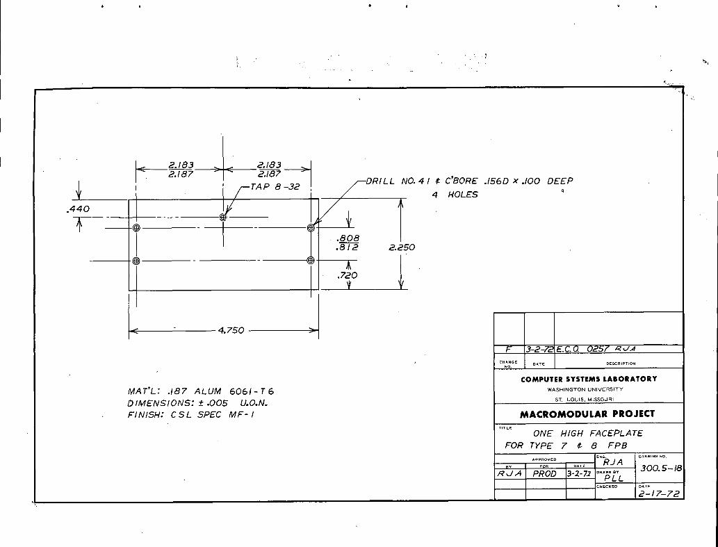
300,5-18 .__.j ONE HIGH FACEPLATE......... FOR TYPE 7 AND 8 FPB F
300.5-19 CONNECTOR STRUT TYPE 1 I
300.5-20 CONNECTOR STRUT TYPE 2 I300,5-21 STRUT COVER I
300_5-22 _ IN TERL. OC_K PiN I
._3300',,5-23 TYPE 10 FILLER STRIP jJ
___3g0_._-__2(1 _ TY P E :1() FAC_EPLA1' E J300.5-25 TYRE °!A FACE PLAmE ........ K
300°5-26 TYPE 9 FACEPLATE K
_3_00_.5-27 TYPE. 9 F.PB PC BOARD K
300,5-28 TYPE 9 FPB PC BOARD ROUTING OUTLINE K
CHG. E.C.O. DATE APPR. CHG. E.C.O. DATE APPR. CHG. E.C.O. DATE APPR.
ISSUE 0 0 .::]'_ ?-,,,7,._- _ ,._. E 0255 2-8-72 _ _'.A,,_.., J 0292 6-13-73 '_ '"/4
r_ 0 0 6'"5 I0-- fl' 70 _'_..,._'"_,_/n-_ F 0257 3--1 --72 ,C_ k/ ? K 0300 11--7--73B 0059 J10-20-70 G 0259 4-4-7'2 /_f_/_
C 0066 110-23-70 ,/_,,f,_ _ 0280 1-8-73 'q _/'4, I
D 0229 11-1-71 _ _,J,,_ I 0290 5-24-73 jMACROMODULAR SYSTEMS PROJECT
300,5-1
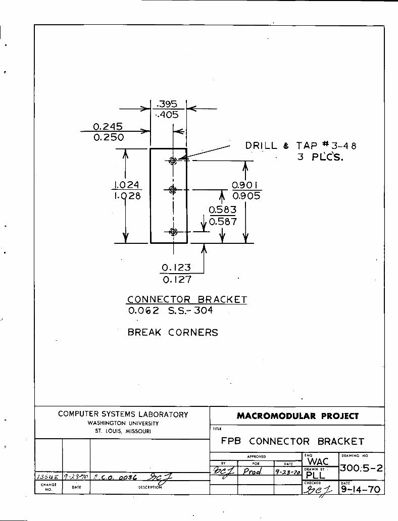
__ .395 j'_ -.405 -"
0.245 _f ._O. 25O
, _ _ DRILL _ TAP ,r3_48f ] PI'C'S.
II
1.024 _._.. 0.90 I, ooosJ 0.583
.L._ o. o7
i
O. 1230,127
CONNECTOR BRACKETO.OG2 S.S.- 304
BREAK CORNERS
COMPUTER SYSTEMS LABORATORY MACROMODULAR PROJECTWASHINGTON UNIVERSITY
ST. LOUIS, MISSOURI TITLE
FPB CONNECTOR BRACKETI
APPROVED ENG I DRAWING NO.
,, i ,OR DATEWAC iIDRAWN.. i300:5-2
:_._ Pro_ ?-_-7_ PLL 'CHANGE _ CHECKED DATE
No. DA,E D._.,..oN --'_e ::Z' i9--14--70//'
I
.161 _--
SI I T
16 i I
t
¢ 3-48 STND MACHINE.$CRE'W THRE.AD
DIM' +-.005
MA TE.RIAL ' $ S
COMPUTER SYSTEMS LABORATORY MACROMODULAR PROJECTWASHINGTON UNIVERSITY
ST. LOUIS, MISSOURI TITLE
FPB CONNECTOR BRACKET SCREW
APPROVED ENG DRAWING NO.
. ,oR I _A,_ WAC
_,s,mE_-2_,7o _-.c.o. oo..,_ _.._,_ . ?_'Z.. ?,.,,,,*. '_-2._-;,,"'PUL 300.5-3CHECKED DATE
c...O..o, DATE DE,C,"T'O"_ I _'C_Z_ 9--14--70f,./ /
I
I 16I
I....... 1
MATERIAL: ALUM 6062- T651DIMENSIONS: ._.+.005SCREW MACHINE STOCK
COMPUTER SYSTEMS LABORATORY MACROMODULAR PROJECTWASHINGTON UNIVERSITY
ST. LOUIS, MISSOURI TITLE
- ASTROSTAND-OFF
APPROVED ENG DRAWING NO
' I ,o, OAT, WAC
C.ANGE _,_ _ DATENO OATE OESCR,PT,ON 9--14--70//
t'
i'< i 4.250 _ > _ 0.080
0.200 _ 3.850 '_
0.3;5 > < 3,6200.0650.070
t o L j ro-,,ol0.750
oioo T8REAK LONG EDGES ¢ CORNERS .020 % X '
ii
ISSUE 9-23-70 CHG.E.C.Q 0036 _r._.fl'
MATERIAL' .062 ALUM 2024- T3 c.o I D.............DIMENSIONS.' !'005 U.O.N COMPUTERSYSTEMSLABORATORYFINISH; CSL SPEC MF ! W^SH,N_'rONU.,VERS,T¥
ST LOUIS,MISSOURI
MACROMODULAR PROJECT_l_LE
FPB -KEYI
^...ov_o EWG. D.^WI.G.0WA C
gY_,, ....D,,..._ 300.5-5
?"'_¢._ '¢L',9__,o

CENTER LINESOFALL m_'JO
HOLE PAIRS COINCIDENT .003 T.i.R,
ANOi[] ,30' /_DRILL '_43
.I,98->-Typ '_- " _,_ //10 PLC'S
.231-->' -
I 90 °--30'
DRILL "_'SO-----x /--"DRILL 4_1'45
. 2 pLC_SI0 PLC_S
.140 .230I--'<----/.B2S---_ H 1-8-73 EC.O. 0280 _ J.A
G 4-4-72 E.C.O. 0259 R _ _4
2.000 _ D !10-27-?1E,C.O. 0229 '_h.T'/Y"
4 _- ......-,_1 _ _'_- NO . DATE . DESCRIPTION
COMPUTER SYSTEMS LABORATORYWASHINGTON UNIVERSITY
ST. LOUIS, MISSOURI
TOLERANCE U.O.N. MACROMODULAR PROJECT.XXX -.*.005 MAT'L : 3003-1-114 ALUM .040 THICK .....
·XX -+.01 FINISH: ALODINE FUNCTION CODE SWITCH BRACKETX + I REQ.'D: IX - 64 I..............
........ , RJA, ......... 300.5-6
,' 'r PROD /0-2.5' ........DHOCHECKED DATE
;_-/ 9-29-71I

i_ 2.183 ' I 2.183 _l
2.187,, > '_ 2.'_787 _ /
< 1.4SO _ 0,450 "< DRIL,I_,_,IV_41 ¢-. CTRBR. .156 D X O. lO0 DEEP
1.320 >_ _ 0.325
i !iI _TA P 8-32 , I I
I SECTION AA_ _CTRBR .3_oDxo3o /_0.808 _'"'_ .... CTRSNK 82 FROM REAM2.250 0.812 1-- BOTTOM OF CTRBORE ' .275D 4..001
I 4 HOLES _ -' ' 0.650 __
>_o30
e _ o * - j< 0.906
_---_.00 ,--_$_ 0.650--_'""_--0.650 1.327-- I 2000
'--TAP 2-56 2 HOLES _5 0,906
i II I ii ; _? r--4 .......I I I IIII I
i i
I I I I m
,, I il ,, " I /il _ " il ii D 10._-_-7, E.C.O. 0229 ,_,..,',4
i [ [ i iss_,23_Ec00036_COMPUTER SYSTEMS LABORATORY
WASHINGTON UNIVERSITY
ST. I_OUE$, MISSOURI
MATERIAL: .187 ALIiMINUM 6061 - T6 MACROMC)DULAR PROJECTDIMENSIONS: -t- .005 U.O.N. _,TLE
FINISH: CSL SPEC. MF ITYPE I FACEPLATE
....... WA CBY
,___ PROD. 5-,_4¢D .......300.5-7
6' PL L
5-19-70

.275D _+.001 C'80RE .343D _ .030C'SINK 82 ° FROM BOTTOM OF C'BORE
NO. 41 · C'BORE 24 HOLES.IS6D x .100 DEEP
4 HOLES
® ®
)-I I I I r I r I I ,.o3s {0.720
-- 0'6" l
DRILL NO. 4 2.183 2.183 SECTION AAS HOLES 2.187 2.187
_.750 _ I
TAP 2-.562 HOLES
IISSUEI_3.7OIE C O 0036 _._C._
MAT'L: .187 ALUM 6061-T6 COMPUTER SYSTEMSLABORATORYDIM: _+.005 U.O.N. W^S.,.G?ONUNIVERSITYFINISH: CSL SPEC MF I
ST, LOUIS, MISSOURI
MACROMODULAR PROJECT*ITL_
TYPEZ FACEPLATE
, ..;.ov,_, .... [""WAC ..........300.5-8
/
_ 4.750
1.40C _, _ 1.400 ?
_- TAP
'x_8-32
¥ ,
o°:_1_ + _25o
DR,LL_Z_,._E< 51,g5 >_- 5:¢[5 >.156D X .100 DEEP
16 HOLES
0.906
/_ _ / E.C.O.0036 J_c_.i OE_"J"TION_'
COMPUTER SYSTEMS LABORATORYWASHINGTONUNIVERSITY
MAT'L : .187 ALUM 6061-T6 s_: LOUIS,MISSOURI
DIM: -+.005 U.O.N. MACROMODULAR PROJECT
· OD FINISH.' CSL SPEC MF I .....
TYPE 3 FACEPLATE
-':::-, .... I............."_ .._.. , 300.5-9
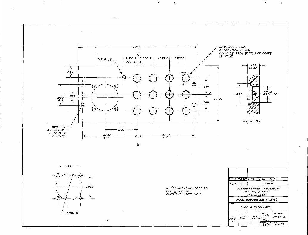
4.750 _' /--REAM .275 D ±.001
_C'BORE .$45 D X .030 OF
, --®-{ )-Q-®-(60 _
._/_ _ I _ LI ._o _._o
· )-- _ __
, -j_.
DRILL '_Zl I _,¢ C'BORE .156D lc L320
X .100 DEEP
8 HOLES .2.183 2.183
i - c.CO.0036 '_'fZ-OESC.t.T,O~
I -- '--iL----- H- 0.906 MAT'L; .187ALUM 6061-T6 COMPUTER SYSTEMS LABORATORY
/i _ ' DIM:_-.OOSU.O.N. w^_,.G_o...........
/FINISH;· CSL SPEC MF I sT. UOU_S,MISSGURt
--_ MACROMODULARPROJECT
TYPE 4 FACEPLATE
TITL_
· D ^Pp.ov£_ _... OR^W,NG.o.
o WAC .300.5-10

2.183 _It 2.183< 2./87 ri-- 2.,87̧ >
-L1._6o =1- 1._6o
I _A_8-32-_--_ _-.2oo
I , , ooooo,.o2_ ©_ ©
I ' * ¢I ' .230
2.000 >l.C 4,75 0
.906 ']r I
A10.11_0 _.C.0. 0052
ISSUE _-23_ _,C,O. O03_MATERIAl: .187 ALUM 6061- r6 "°'
DIMENSIONS: __.005 U.O.N. COMPUTER SYSTEMS LABORATORY
FINISH: C51 .SPEC MF-I "^S.'NGTONUNIVERSITYST LOUIS, MISSOURI
.....MACROMODULAR PROJECTTYPE 5 FACEPIATEI
O^TE · _"G C.J
DRAWINGNO.APPROV_O
d/
:_¢ °3L2z-;'o6/

DRILL NO, 35 C'BORE
.187 X.OPS DEEP 2 HOLES_
I .125 _/
_ +I_ 3.965 _1
-_ 4.250
IB I0-20;'0 g.C.O.0059 _]_
ICHANGE
MATERIAL' .125 2326 BLUE, TRANSLUCENT PLEXIGLASS .o ,,..............TOLERANCES: -+ 0.005 U.O.N. COMPUTERSYSTEMSLABORATORY
WASHINGTON UNIVERSITY
ST LOUIS, MISSOURI
MACROMODULAR PROJECTTITLE
FPB REAR CONNECTORFILLER STRIP
CNG* DRAWING NO.
........ N TKPROD. '_*/70 ....... 300.5-12&.,/_ PLL
CHECKED OATE
,,cgd _ 10-19-70
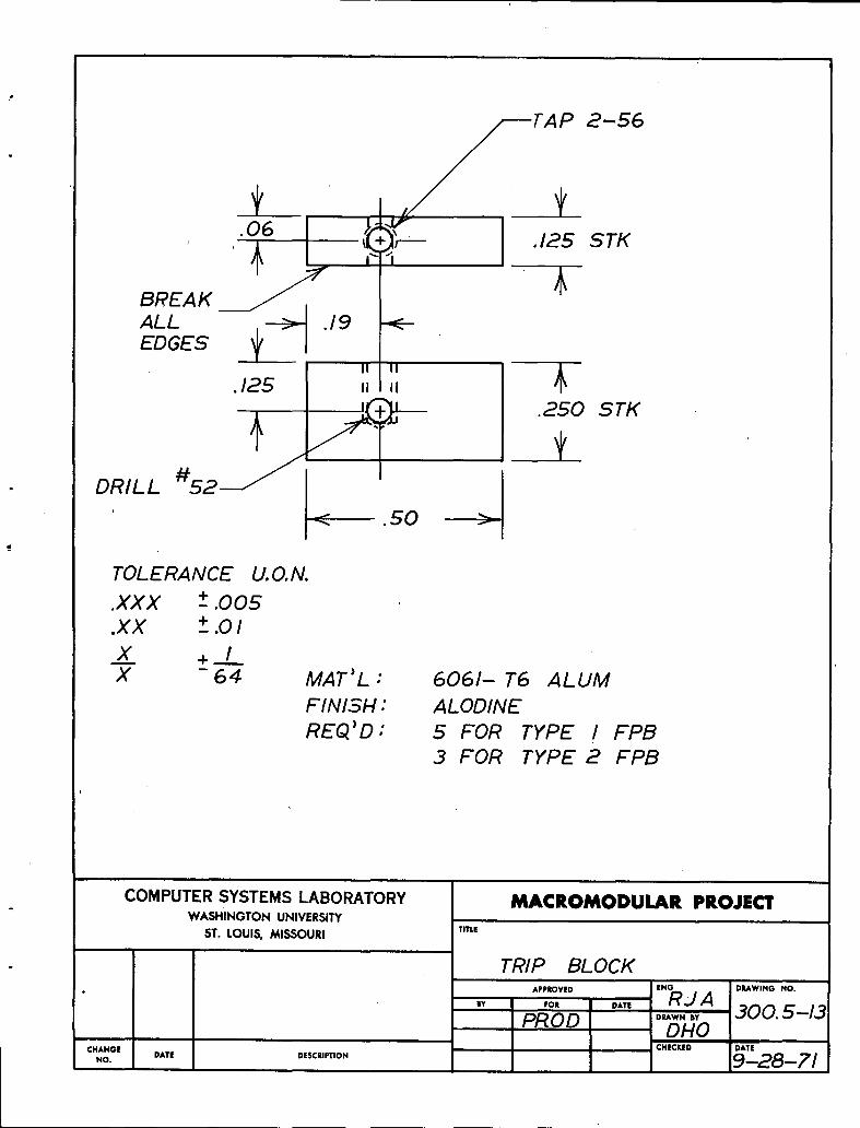
I-AP 2-56
, .06 STK
ALL _ .19 ..<---
EDGES
II II.125 ,i ii
J 50 '-_i
TOLERANCE U.O.N.
.XXX t .005
.XX +-..0I
X + IX - 64 MAT)L: 6061- T6 ALUM
FINISH: ALODINEREQ'D ; 5 FOR TYPE I FPB
3 FOR TYPE 2 FPB
COMPUTERSYSTEMSLABORATORY MACROMODULAR PROJECTWASHINGTON UNIVERSITY
TITLEST. LOUIS, MISSOURI
TRIP BLOCKA,.O.O ,.G °,.,.,,.o.o.
,, ,oE °A,, RJ A. °,,,,,., 300. 5-13· PROD DHO
ICHtCKED D).T!
CHANGE °ATE .,c.,.,o. q--_--7/NO.
i i

CFIAM. .010 MIN. x 45 °
OTHI I 0
+ I
-' TOLERANCE U.O.N.
.XXX +-.005.XX --.01
MAT_L : .062 DIA. S.S. RODFINISH: AS MACHINED
REQ_D : 5 FOR TYPE I FPB
S FOR TYPE 2 FPB
COMPUTERSYSTEMSLABORATORY MACROMODULAR PROJECTWASHINGTON UNIVERSITY
ST. LOUIS, MISSOURI TITLE
SENSE P/NA.EOVED E.G 0_.,.0.0.
,, ,o, RJAPROD I OAT,o,*w,,, 300.5--14--_ DHO
CHANGE CHECKED DATENO. DATE DESCIIPTION 9-28 -71

DETAIL B
v-DRILL NO. 41 ¢ C'BORE _ .275D ±.001
_lS6D X.lO0 DEEP 4 HOLES C'BORE .343Dx.030T<DETAIL B > 0,500 C'SINK 82 ° FROM
BOTTOM OF C'BORE
! ¢'BORE
33_64 D x 0.0,5'5 DEEPO0
_ ,
, , STOCK
o°:_'°_ i' 0.`343D .2__.oo1
, 1.200 l _ 5l)
0.720
__ I__ __ I __ oBooDRILL NO. 49 > < · 0.030
S HOLES 1.323I.--_7- SECTION AA
_, 'AP 2-56
2 HOLES
2.18`3 2.18.32.187 < 2.187
4.750 [ 2-a-?z. z'.c.o, oz...'_
COMPUTER SYSTEMS LABORATORYWASHINGTON UNIVERSITY
MAT'L: .187 ALUM 6061-1'6 s'_ LOUIS,MISSOURI
DIMENSIONS: _+.OD5 U.O.N. MACROMODULAR PROJECT
FINISH: CSL SPEC MF I .....TYPE 6 FACEPLATE
^...OVED _N_URI' O.^m.G .0,
.... _...... 300. S-ISC,_ 2/?°`0 _SF,._._PL L
:.E.CK£O O^T_
,_,JA 11-1-71
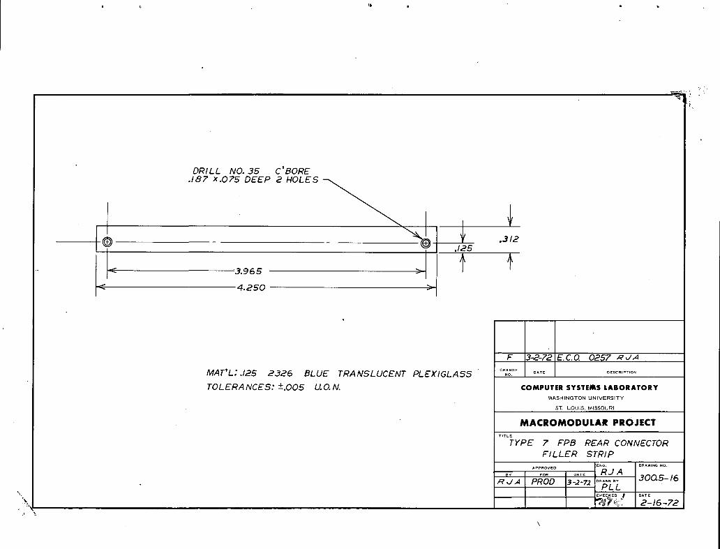
DRILL NO. 3S C'BORE
.187 x.07S DEEP 2 HOLES _
m
%,I.125
F 3-2-72E.C.0. 0257 ,_d,4CHA_GE
MAT'L".I2S 2326 BLUE TRANSLUCENT PLEXIGLASS NO. D..............
TOLERANCES: -+.OOS U.O.N. COMPUTER SYSTEMS LABORATORY
WASHINGTON UNIVERSITY
ST LOUIS, MISSOURI
MAC:ROMODULAR PROJECTTITLE
! TYPE 7 FOB REAR CONNECTORFILLER STRIP
APPROVED :ENG. DRAWING NO.
.... RJ A
..... io__.L 3oo.s-,sR dJl PROD 3-.2-?._
" '¢.[c,_dQ t'_ DATE
\% [27F_;: 2-16-72
\
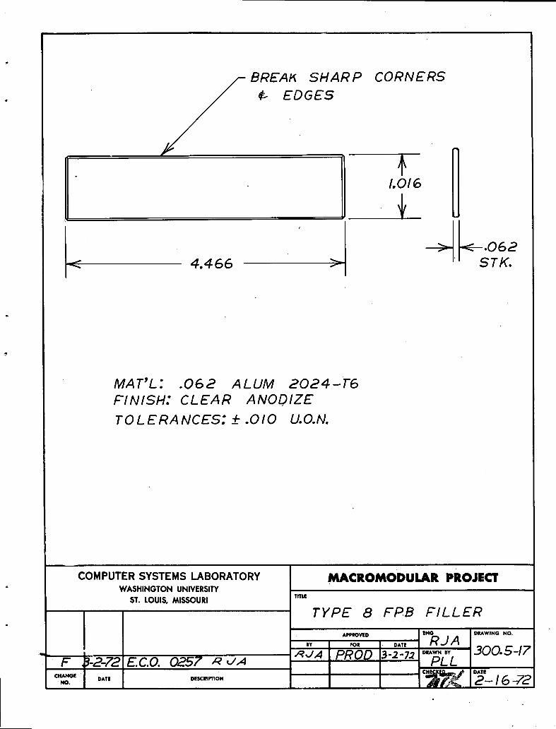
BREAK SHARP CORNERS
1,016
.,
_- 062-_ -4.466 __ STK.
MAT'L: .062 ALUM 2024-1'6FINISH: CLEAR ANODIZE
TOLERANCES: -'1'.010 U.O.N.
COMPUTER SYSTEMS LABORATORY MACROMODULAR PROJECTWASHINGTON UNIVERSITY
ST. LOUIS, MISSOURI TITLE
TYPE 8 FPB FILLER
APPROVED ENO DRAWINGNO.
,, ,o, DA,, R.JA- ,_JA PROD 3-_-7_ D,,,w.. 300.547
F ._-2-72 g.c.o. 0257 ,_ ,,,.4 PLL
CHiClE _ DATECHANGE ' DATE DESCRIPTION 2-- I 6 --72
NO. , j
L', ' *' ' ' '...... , I
L_ 2.183 _ j 2.183 ._
_ 2.187 _'_ 2.187
, //---TAP 8-32 /_--DRILL NO. 41 ¢ C'BORE .156D x.lO0 DEEP.440 '/
.808·8 12 2.250
.720t
F 3-2-72 E C.O 0257 _ <./.4
CHANGENO , DATE DESCRIPTION
COMPUTER SYSTEMS LABORATORYMAT'L' .187 ALUM 6061- T 6 WASHINGTONUNIVERSITYDIMENSIONS: _+.OOS U.O.N. sT.LOUIS,MISSOURIFINISH: CSL SPEC MF- I MACROMODULAR PROJECT
TITLE
ONE HIGH FACEPLATE
FOR TYPE 7 ¢ 8 FPBENG, DNAWiNG NO,
........ RJ A. .... I .... 300.5-18R,J,,4 PROD 3-2-7.2 .......PLL
CHECKED DATE
2-17-72

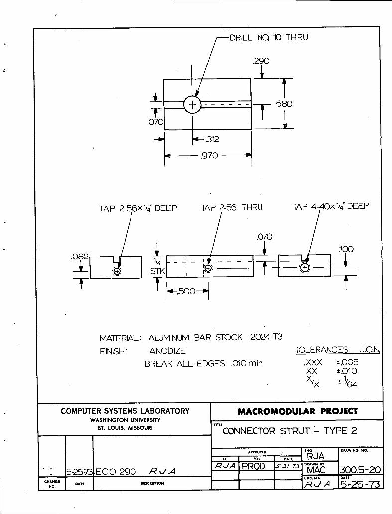
.290
-- .580
r T l.070
= .970 _--
TAP 2-56x_d'DEEP TAp 2-56 THRU TAP 4-40x "/4"DEEP
.070· [:I' -'t i.,_oo_.t _'
MATERIAL: ALUMINUM BAR STOCK 2024-T3
FINISH' ANODIZE TOLERANCESU.O.N.BREAK ALL EDGES .010 min .XAX +-..005
.XX '".010
X/x .,.1/64
COMPUTERSYSTEMSLABORATORY MACROMODULAR PROJECTWASHINGTON UNIVERSITY
ST. LOUIS, MISSOURI TITLECONNECTOR STRUT-TYPE 1
=.o.I o..] o,_.,-,o. ] _;_:>__ 15-25-'73
DRILL NO. 10 THRU
.290
I lb
_ T.070 _F
--_ 4- .312
--.- .970 -"
TAP 2-56xl/4" DEEP TAP 2-56 THRU TAP 4-,40xl/4 ' DEEP
/070/ i©.082 ,, j1/4 -- _ _
I F/'2Y "Il __· "' _ STK ' ,'_' /
r k._ooH 1'
MATERIAL: ALUMINUM BAR STOCK 2024-T3
FINISH' ANODIZE TOLERANCES U.O.N.
BREAK ALL EDGES .010 min .XXX '".005.XX '".010
x,x __1,64
COMPUTERSYSTEMSLABORATORY MACROMODULAR PROJECTWASHINGTON UNIVERSITY
TITLE
ST. LOUIS, MISSOURI CONNECTOR.STRUT - TYPE 2
ENG DRAWINGNO.
A,,EO,,ED, RJABY FOR DATE
.q,xA PROD ,¢-3/-73._,_ 300.5-20' I 5-25:7"31,EC 0 290 /:_ ,J.,4 CHECKED DATE
c.A.,,,.o.DATE .,,,C,,",O. _,./ A 5--25 --7"5

I i
DRILL .096 2 HOLES
J
i
I 1.575 1.775
I
I 0 ,r_ ,
_.5oo-- I .loo1.125 _-- .125
I F TOLERANCESU.O.N..XXX +.005.XX -+.010
MATERIAL: .030 ALUMINUM 3003 H14 X/X +_1/64FINISH: ANODIZE
COMPUTERSYSTEMSLABORATORY .MACROMODULAR PROJECTWASHINGTON UNIVERSITY
TITLE
ST.Louis,MISSOURi STRUT COVER
A,,,,o,,,. ,.° °,,,,¥,.°.°.IY FOR DATE .RJA
,_,JA PROD ..¢-3,-?..,'°_,_. 300.5-21I 5-24-72ECO 290 ._,./,4' CHECKED DATE
CHANGE DATE DESCRIPTION _ _ ,_ 5--24 _/-5NO,

PRESS FIT AND CENTERO
·300---_ 4--- lac" CADMIUM PLATEDROLL PIN 3/8" LONG
r_
.075 _ /'-'"'"'--//_AS° .187 D +-.005,i
BREAKEDGE
BOTH ENDS _-T .600 --_
MATERIAL: STAINLESS STEEL .187 Dio.
TOLERANCES'".010 U.O.N..
! COMPUTERSYSTEMSLABORATORY MACROMODULAR PROJECT: WASHINGTON UNIVERSITY
ST. LOUIS, MISSOURI TITLEINTERLOCK PIN
APPEOVED ENG DRAWING NO.
. ,o. I o,,, RJAI
I 5-25-_ ECO 290 _JA ,,,_,.J,,4PROD .,-----3/-75°_ 300.5-22CHANGE I I CHECKED DATE
.o. .,..E DE,,C.,.,O. .g ,./,4 5- 25-73i

DRILL NO. 35 C' BORE.187 x.075 DEEP 2 HOLES
.188
.768
ii
i · I
4 3.965 >----_ ! ,.I--- .142_" 4.2507'
MATERIAL: .125 BLACK PLEXIGLASS
TOLERANCES: + .005 U.O.N.
COMPUTERSYSTEMSLABORATORY MACROMODULAR PROJECTWASHINGTON UNIVERSITY
ST. LOUIS, MISSOURI TITLETYPE I0 FPB FILLER, STRIP
i APP_VEO ENO DRAWING NO,
,. ,o, i DA. RJA 300 5-23O 6-13-73 ECO 0292 RJ/f PROD _'"-3/-_ D_._._:I 5-24-73 ECO 290 ,A,,./,,4 ; ·CHANGE CHECKED DATE
No. DATE D..C.,.,O. _ R _ [ 5-24-73i
,,'..
_f
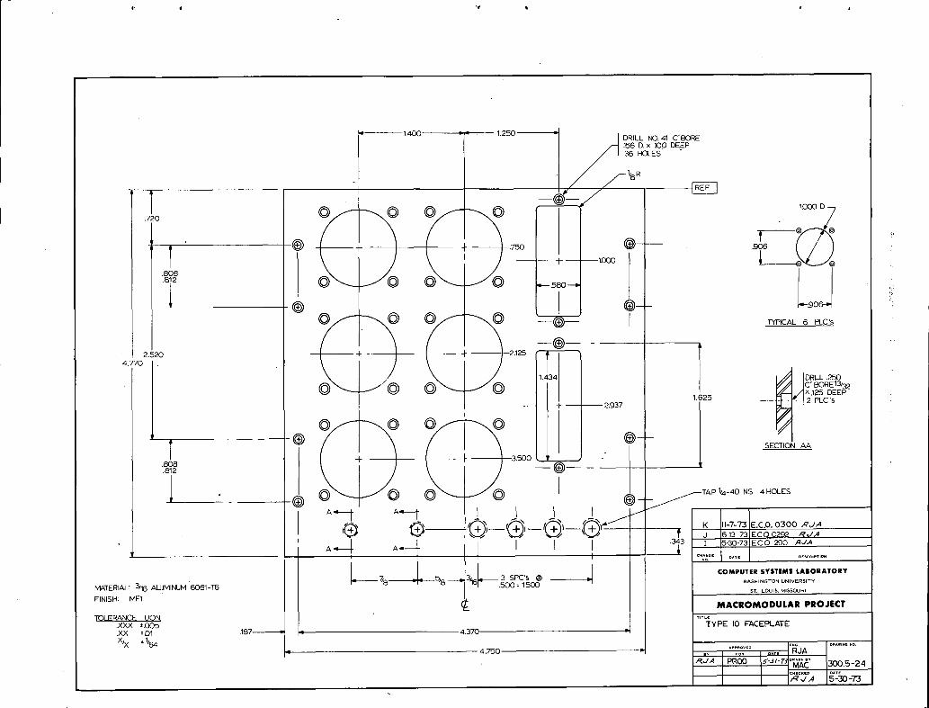
,,,,' 1AO0__ 1.2'.'.'50 - [ DRILL N0.41 C'BORE/'_ .156 D. x :100 DEEP
I36 HOLES
._[o © © © :1'°°°D,7
.808
.812 ..
© © © [ _P_,,L6_,c,s
®- ,)2.520 __ + __ I /
'© v,-.,,mc'mRE13_,6. _'_t$7L'· 2.937
I
© ©
'TT SECTION AA8o8 + -- _--.812 --
I '® _ _ 1/4-40 NS 4HOLES
· -- i *'--t IK 11-7-_E.C.O.0300,_'J._'_' J 5 13 73 ECO 0292 _',,/,4
A-- I A_-_ 5/8--!__'_6 ' .343 I 5-30-73 ECO 290 ,_J,4
COMPUTERSYSTEMSLABORATORYMATERIAL: 3/16 ALUMINUM 6061-T6 7/8 -_- 3 SPC's
' .500: 1,500 -I WASHINGTONUNIVERSITYS_ LOUIS,MISSOURI
FINISH: MF1 MACROMODULAR PROJECT
TOLERANCEU.O.N. _,*LE.XXX_.005 TYPEI0 FACEPLATE.XX -+01 :187 4.370
_NG. DR^W,.G,O........ O,, RJA
X'x '% 4._o _L;,,P_oo""_-,,-r,"_;;_' _o.s-2,¢.tcKto O*T__U,4 5-30-73
"'1'
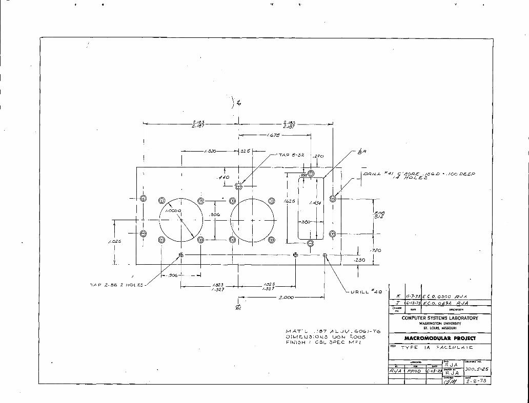
2./,_,_ £.1,5.5 >
-- Z_7_
TAP 4¢-,._2 , 20
f /-- ,_,q// ,z,, '_ WI C '/ZO,Z_E ,/,_G _D _ ./00 Z_.E_,_P
/,4 ,,'7'o/.. z_
t _I
_ _Z_
* Jt,Z,¢o
ITAP _-,.-%6 2 HOLED- _ Z325 /;,,525 __
/.,327 /.$37 BiLL "_4g '
_ 2.00O K 11-7-75 £,¢,0, OSO0 RJ.4
3- i 6-/._-;'$ E. CO. O,Zg,Z ,_.J,4
C'AHGE DATE D_SCRIPTIOP4m
COMPUTERSYSTEMSLABORATORYWASHINGTON UNIVERSITY
ST. LOUI_ MISSOURIivlAT'L, .1_7 ALUM.. GOGI-TG
o{_4_u_loMo uoki _oo6 MACROMODULAR PROJECTFIk.llbH : CbL bPF__.C NdFI.
Tm. TYPE IA FACE-PLATE
_,.*IOWD [NO D_wl**4o NO.d AIY o,.
RJA
_R/_ #4/ C'_O,_£I
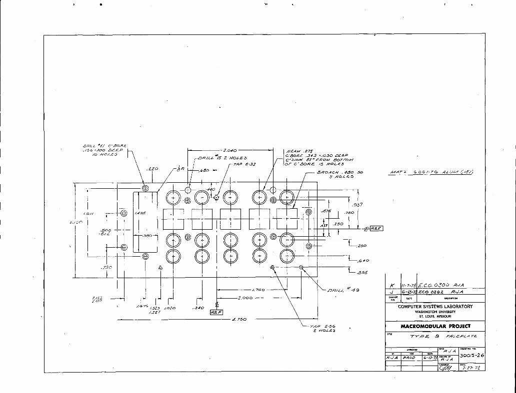
,/_ ;lO0 D_P _ 2.040 J ,C£AM ,ZTCY
%/o
' -_o_)z__S 2 HOZ_ /--]c'_//¢*'8_°F_o_ ' z_ofTo_-¢
OL _P
t _7,_, _ 8-32 ' fOE C'Z_:_R,C /_ HOLl5
ZiO -_R ,_o
2,;_'0 .2 0 I 1· _ _,_r-r;'l
\ -- .
5> (> (->>(> (_ _-o
IIi; "<!¢,If' //-7-?_ z, J_-.CO. O JO0 ,,_JA
/, woo --
_._--;:,__.o,o ._,o _o,,,,,%._j2o?,%,_2o,,,,,',-o..,ST. LOUIS,N_ISSOURI
,4'. 7.50
_p z _ MACROMODULAR PROJECT
I
6/?'-,',4 ,_I_'o,D &_13.73 ..w. ,, ,._,_.._.,,',-''._R.Z A
Ii
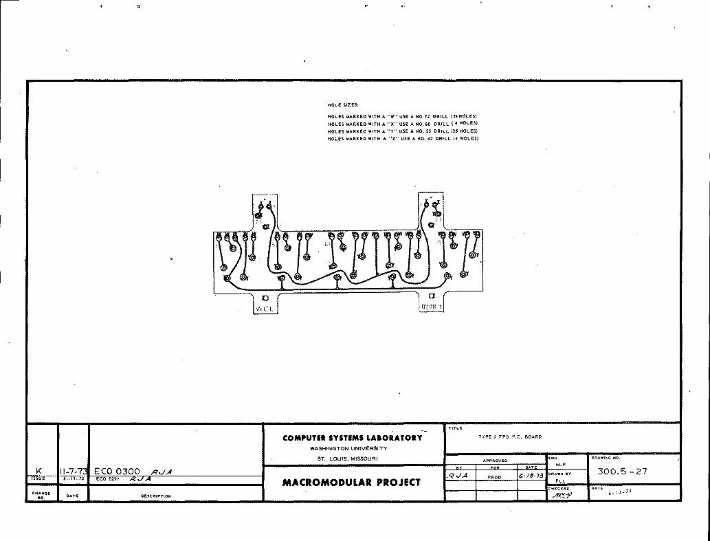
HOLE SIZES:
HOLES MARKED WITH A "W" USE A NO, tZ DRILL (24HOLES)
HOLES MARKED WITH A "X" USE A HO, G0 DRILL (4 HOLES)
HOLES MARKED WITH A "Y" USE A HO. 55 DRILL (25 HOLES)
HOLES MARKED WITH A "Z" USE A NO. 42 DRILL (4 HOLES)
?
/ v¥cL1 I °2')_:_/
TIT[.[
! COMPUTER SYSTEMS LABORATORY'" TYPE_ FF'BP.e._O^RDWASHINGTON UNIVERSITY
ST. LOUIS, MISSOURI APPROVED ENG. DRAWING NO.MLP
BY FOI_ DAT_
K 11-7-73 ECO 0300 RJA _J.4 ,Roe, _-/,,S-TS....... 300..5-27ISSUE 6-13-73 ECO 0292 /-_ _/,,_
c.,.oE ' MACROMODULAR PROJECT :._.o_LL .... ,_1_-_NO. OATE DESCRIPTION _F_ _- I Imil I ,
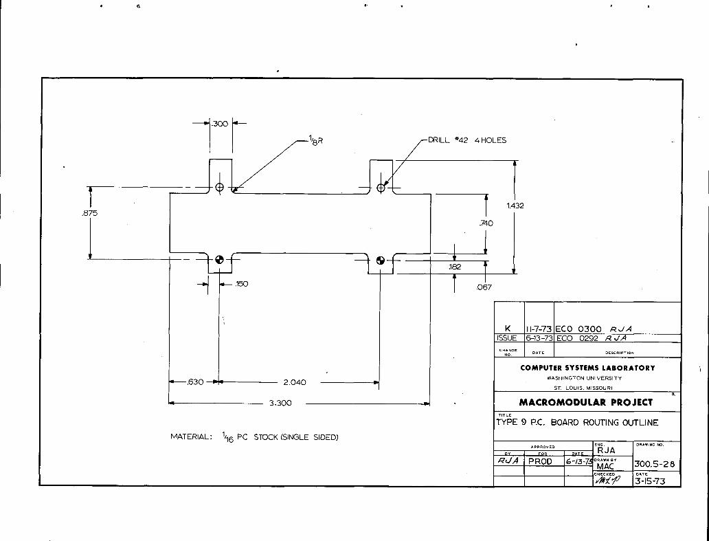
.300
1(j__I/8R ,__--DRILL _'42 4HOLES -
T -- T 14_.875.740
?f If T_ _.1_o T .o_
K I-7-73 ECO 0300 _,./,4ISSUE 6-13-73 ECO 0292 /_,//4
CHANGENO , DATE DESCRIPTION
COMPUTER SYSTEMS LABORATORYWASHINGTON UNIVERSITY
'_.630 -,- 2.040 v I s'r LOUIS, MISSOURI
4, 3.300 _, MACROMC)DULAR PROJECT
TITLE
TYPE 9 P.E. BOARD ROUTING OUTLINE
MATERIAL: 1/16 PC STOCK (SINGLE SIDED)ENG. DRAWING NO.
........ RJADATEFOR
_,4 PROD *-/5-7._0_X_ 300.5-2 8

,o.,u,,.,.,,,., .,,o.,,,o.. J30061WASHINGTON uNIVERSITY °
V-BUS SUBASSEMBLY
PAGE TITLE CHANGE
300,6-1 TITLE PAGE ISSUE
300_6-2 V-BUS SUBASSEMBLY - ASSEMBLY SPECIFICATIONS
300_6-3 V-BUS SUBASSEMBLY AND PARTS LIST
300,_6-4 VEIRTICAL BUS BOARD ARTWORK AND BLANKING DIMENSIONS
IIIi
CHG. E.C.O. : DATE APPR. CHG. E.C.O. DATE APPR. CHG. E.C.O. DATE APPR.
ISSUE 0046 10-7-70 _ , I
(/ i
i
MACROMODULAR SYSTEMS PROJECT
300,6-1

V-BUS SUBASSEMBLY
Assembly Specification
I. Introduction
The V-Bus subassembly' consists of two connectors, a printed circuit
board, and two support brackets as shown on the overall view (Dwg. 300.6-3).
The printed circuit board is defined by drawing 300.6-4 and the support
brackets by drawing 300.5-2. The special connector bracket screws are
shown on drawing 300.5-3. Refer to document 300.0 for identification
of the V-Bus connectors.
II. Assembly Procedure
The two connectors shall be applied to the circuit board, and held
in place by masking tape, or other suitable means. The two support
brackets are then to be attached to the connectors with the special
screws called out in the parts list. The assembly may now be soldered.
III. Soldering
The assembly may be hand soldered or wave soldered. Hand soldering
shall be done only with a temperature controlled soldering iron (Weller
W-TCP iron with a 600 degree Fahrenheit tip or equivalent). In the
case of wave soldering, care should be exercised to preserve the align-
ment and seating position of the circuit board.
The connectors must be flush with the surface of the circuit board
at the three points of contact on each connector block. The distance
between any one of these contact points and the circuit board shall be
less than 0.010 inch after assembly. The solder used shall be of
nominally 60% tin and 40% lead. Any convenient flux may be used pro-
vided that all flux residues are removed from the finished assembly.
No flux shall be allowed to enter the connectors, and the'flux cleaning
process shal'l leave no residue on the connector block or gold contact pins.
CHG. E.C.O. DATE APPR.
Issu 0046 10-7-70//
300.6-2i

r
CONNECTOR BRACKET
'"VERTICAL BUS BOARD FP8 CONNECTOR BRACKET SCREW
.....=...._! CONNECTOR m:.... '
iQT\' CSL OOC I P&RT i
..... I 300.6-4 i _/ERTfZAL _US _OARD i
2 3O/}C ' __ V-_,US CONNECTO, _
........ =_.j......_'...........................'.............· 4 3,_,5-'I ' FPB CONI4ECTOR _RACt'LET :_CREW
COMPUTER SYSTEMS LABORATORY V-BUS SUB-ASSEMBLY AND PARTS LiSTWASHINGTON UNIVERSITY
,, , ;, .............ENG, O_^WI_G ,_O.
ST, LOUIS, MISSOURI A,PPROV/_D ._._].BY FOq,, , 08TE: ,
issueto-z.zoL=.C.aoO4,-'j_¢_:_ : )e¢- _'_o_,._-..,,.,o_,.......... _,,, ..... M&CIOMODULAR PROJECT u ,,, _.........
,,, C_*ECK_O ,.._ D&TE
c.,,.oE ,z;,!.?(';,' 10 7 :r,NO. DATE DESCFRIPTION -,.... [ i I Jill II II III ...... r.

e e
PTS0082-1
oooo · oOoOoOoOo_ S,DE_A.......NE....e e ,,OTE:ARTWOR_SUPP_,EOAS
4:1 CRONAFLEX PRINT
o_s,r_ [- £80 O?.Tq
· EXPOSED S(OE
BOARD BLANK DIMENSIONS
iI I
0.469 i I NOTE I: 180 HOLES PLATED THROUGH
I J TYPE 'B'
NOTE 2: REFER TO CSL SPECIFICATIONI _65
, , 73 o?o4 - _OO - O%_O O __ PC-INOM. REI_ I
ilSaL icv?/_.¢O. Ooe4 -.,_ _,
E COMPUTER SYSTEMSL/IIOBATOBY
PLATED THR UGH HOLES,4.... DS?_OTE,; T_O ...................3.3 I 8 MACROMODULAR PROJECT
3.323 ..... VERTICAL BUS BOARD ARTWORK
ANO BLANKING DIMENSIONS

co..u,,,,,,,,., ,,,o.,,o., J3OO7 ]WASHINGTON UNIVERSITY
, FuNcTIONCODESWITCHSUBASSEUBLIES
PAGE TITLE CHANGE
300,7-1 TITLEPAGE B
300.7-2 FUNCTION CODE SWITCH SUBASSEMBLIES - ASSEMBLY PROCEDURE5
3003-3 TYPE 1 FUNCTION CODE SWITCH SUBASSEMBLY A
300,7-4 TYPE 2 FUNCTION CODE SWITCH SUBASSEMBLY
300.7-5 TYPE 3 FUNCTION CODE SWITCH SUBASSEMBLY B
CHG. ! E.C.O. DATE APPR I CHG E.C.O. gATE APPR CHG. E.C.,3. DATE APPR.
re--iss 0229 11-11-71 _,_ ,J,,,_J
A 0247 1-13-72 /iC_,J.,ZJ
n n2q? 6-13-73
MACROMODULAR SYSTEMS PROJECT
300.7-1

1I
Function Code Switch Subassemblies
Assembly Procedure
This document (300.7) describes the Function Code Switch
Subassemblies of all types. To assemble a specified type, the
procedure to be followed for each switch position required by
the subassembly is:
1) Rivet microswitches to bracket with shallow head
rivets being careful not to damage the switch and
making sure that they are placed in the properorientation.
2) At each switch location thread a sense pin through
the bracket, a trip block and a spring as indicatedon 300.7-3 & 300.7-4.
3) Adjust the sense pin extension from the front surface
of the bracket to 9/32 + 1/64 in.
4) Secure the sense pin to the trip block by firmly
tightening the set screw in the trip block.
5) After all switches and activating mechanisms have
been assembled and adjusted verify proper on/off
operation of each switch.
__T _.c;_. _^_: ,,_,__-'"lr;_-_',;'jO--_-C Il-II-,T1 _,/A
300,7-2

NOTEORIENTATION
' FUNCTION CODE SWITCH BRACKET
R '9/32 + 1/64.1 2 3 2 3 1 2 3 I 2 3, 3j 2 1
° £/_T R NIP BLOCK SE SE PIN SPRING
rPARTS LIST
I
QTY CSL DOC. PART
1 300.5-6 FUNCTION CODE SWITCH BRACKET
5 m MICRO SWITCH NO. ' 3SX1-T
5 _ SENSE PIN SPRING .120 OD, .016 WIRE DIA, i
V2 in. FREE LENGTH, 8Y2 POUNDS PER INCH
5 300o5-13 TRIP BLOCK
5 300o5-14 SENSE PIN
i 5 -- 2-56 x 1/16 LG CUP POINT SOCKET HEAD SET
J SCREW CADMIUM PLATED
10 _ .086 BODy DIA x 9/32 LG SHALLOW OVAL HEAD --
NICKEL PLATED STEEL SEMI-TUBULAR RIVETS
COMPUTER SYSTEMS LABORATORY MACROMODULAR PROJECTWASHINGTON UNIVERSITY
LOUIS, MISSOURI Tree TY'PE 1 FUNCTION CODE SWITCH SUBASSEMBLYST.
APPROVED ENG ' DRAWING NO.I
BY FOR DATE RJ A
A 1-13-72 E.C.O. 0247 ' ,,_ ,./,4 .,._e_ pRoo. II-Cz '?1 DRAWNm,Y 300,7-3re-iss 11"'11'7't E__ ri_ N_?_ ,_ ,...J_J (./ MBP
CHANGE CHECKED DATE
E.NO. DA. D,_:,,--,O. ' ._e_ 11-11-71_ 6/
i i · '
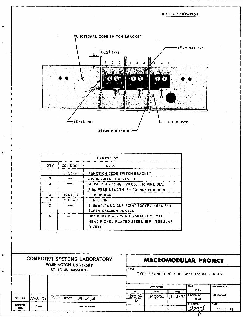
NOTE ORIENTATION
FUNCTIONAL CODE SWITCH BRACKET
/· 2 -I- 1/64
i_ 2 3 1 2 3 3I -- \_'_Ji:'/",'"_"'..'. -- i .!../_\..i_'_';'_;''. _i' ' ' '_' ........ : ''
/ e® ,_
-- SENSE PIN -TRIP BLOCK
SENSE Pi G
PARTS LIST
QTY CSL DOC. PARTS
1 300.5-6 FUNCTION CODE SWITCH BRACKET
3 _ MICRO SWITCH NO. 3SX1-T
3 _ SENSE PIN SPRING .120 OD, .'016 WIRE DIA,
J Y2in. FREE LENGTH, 8_ POUNDS PER INCH,3 300o5-13 TRIP BLOCK
3: 300o5-14 SENSE PIN
3 _ 2-56 x 1//16 LG CUP POINT SOCKET HEAD SET
SCREW CADMIUM PLATED
6 _ .086 BODY DIA. x 9/32 LG SHALLOW OVAL
HEAD NICKEL PLATED STEEL SEMI-TUBULAR
RIVETSi
COMPUTERSYSTEMS LABORATORY MACROMODULAR PROJECTWASHINGTONUNIVERSI3'Y
ST. LOUIS,MISSOURI TiTLeTYPE 2 FUNCTION'CODE SWITCH SUBASSEMBLY
APPROVED I ENG DUWINO Ho.
BY fOR I DATE , R J A
__;7¢.,_- PRot_. iI.i;L_71DIL_WNaY 300,7-4re-Ess //-/fl'Ti' E.C.O. 0229 _ _ "_ _/ I MBPCHANGE i BCHECKED DATE
NO. DATE DESCRIPTION L_p. _I ' 11-11-71
i fl_l._ v/ i i
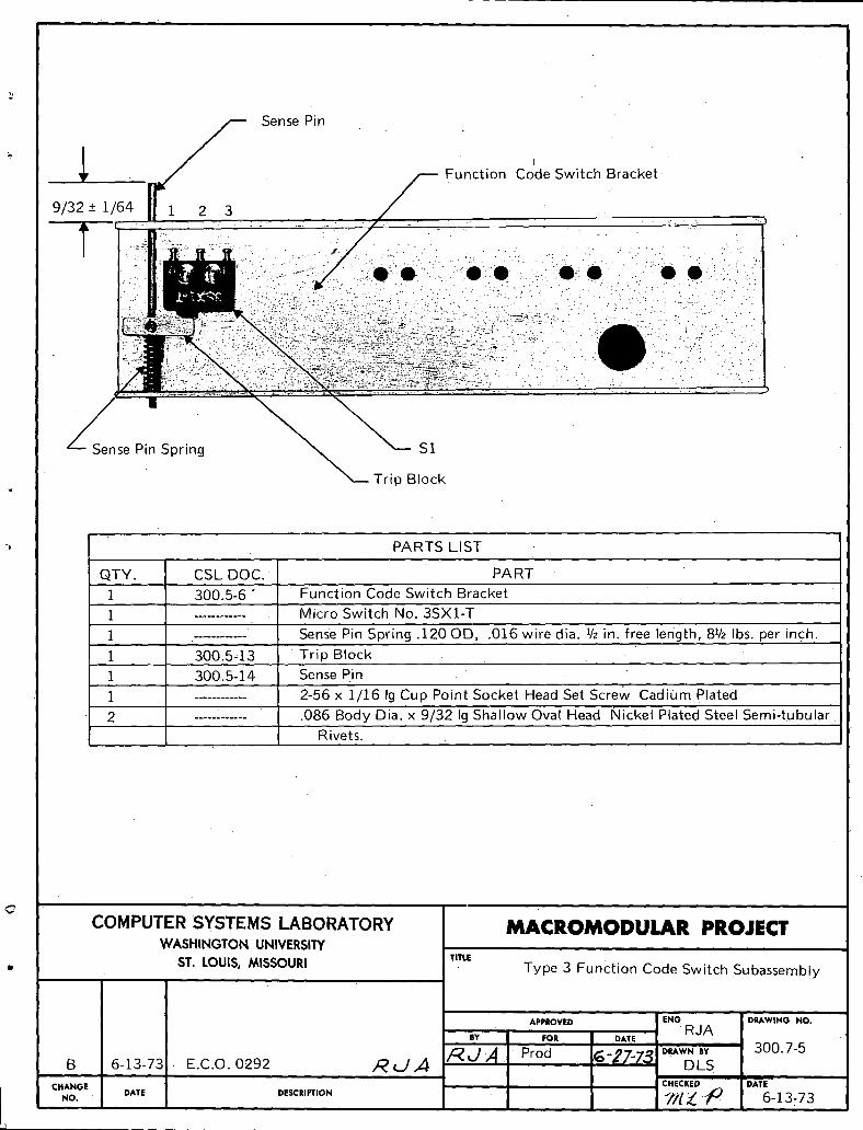
_ _ _ Sen_e_i." ,_ Function Co'de Switch Bracket-9/32 '-+1/64
...... :. · .. :- - · ....
L ' ,,, ,o _: '__:'!:?:;":--ii_ i_:,:!? ; ;:::{:c_:e;'',:/:i,; ;?i:ii:i_?_::;_:/_;; i :i__:ii:::::'_'::i:::_i/;_i_:ii'
? " '_;<:!:]:':_i:_j:'ii:: ;;':? ::'_.ii::!,'?.'::..' i:i_
Pin Spring _ _ Sl· _--- TripBlock
I PARTSLIST
QTY. CSLDOC. PART1 300.5-6' Function Code Switch BracketI ............ Micro Switcl_ No. 3SX1-T i1
- ........... Sense Pin Spring .120 OD, .016 wire dia. 1/2in. free length, 8V2 lbs. per inch. J- i1 300.5-13 Trip Block1 300.5-14 SensePin
1' -........... 2-56 x 1/Z6 Ig Cup Point Socket Head Set Screw Cadium Plated
2 ............ .086 Body'Dia. x 9/32 Ig Shallow Oval Head Nickel Plated Steel Semi-tubular"Rivets.
COMPUTERSYSTEMSLABORATORY MACROMODULAR PROJECTWASHINGTON UNIVERSITY.. ST. LOUIS, MISSOURI TtTLE
Type 3 Function Code Switch SubassemblyI
J
APPROVED ENO DRAWING HO.
BY I Po, J D*TE 'RJA
B 6-13-73 . E.C.O. 0292 ,_ _J',4 /::_J _ I Prod ._'2_'-73 D,*WNBV 300.7-5r
DLSCHANGE
NO. DATE DESCRIPTION CHECKED DATE
'_//_'_ l 0 6-13-73\
UNCLAS S IFIED'_ Security Classification .......
DOCUMENT CONTROL DATA - R & D
(Security classiEicetlon of title, body of abstract and indexinE annotation must be entered when the overall report is classtlled_I. ORIGINATING ACTIVITY (Corporate author) IZa. REPORT SECURITY CLASSIFICATION
Computer Systems Laboratory I T_CLA_SI;I_ . .Washington University t!ab.GROUPSt. Louis, Missouri J
I3: REPORT TITLE
FACEPLATE SPECIFICATIONS
4. DESCRIPTIVE NOTES (2_/pe of report and inclusive dates)
Final Report 4/1/65 through 12/31/73
5. AUTHOR(S) (First name, middle initial, last name)
Gerald C. Johns, Editor
6. REPORT DATE 78. TOTAL NO* OF RAGES 17b. NO. OF REF$
February,1974 80 JSa. CONTRACT OR GRANT NO. 9a. ORIGINATOReS REPORT NUI_I'BER(a)
DOD (ARPA) Contract SD-302
h.PROJECT NO. Volume VII of hart 2
ARPA Project Code No. 655
C, [ 9b. OTHER REPORT NO(a) (Any othernuml_e..rs thatmay be aeei4nedthle report)
d. Technical Report No. 3610, DISTRIBUTION STATEMENT
Distribution of this document is unlimited.
I1, SUPPLEMENTARY NOTES 12. SPONSORING MILITARY ACTIVITY
ARPA - Information Processing
Techniques, Washington, n.C.
13. ABSTRACT
Specifications for the construction of Macromodular _aceplate Box assemblies
are contained in this report. Also included are all electrical and mechanical
specifications for common subassemblies. Certain _eneral assembly techniaues
are specified.
C/
· , . . . ,I
DD _ 1473 RIIpI"ACEIDDPORIdI471'I JANI4'WHICNII! 4)1 OIIOLETE FOR ARMY Ul ir,.. I_CLA,qSIFIFDSecurityCl..lflcEtlon

UNCLASSIFIEDSecurity Classification
14. LINK A LINK B LINK CKEY WORDS
ROLE WT ROLE WT ROLE' WT
Macromodule Faceplate
Macromodule Code Switch
IrNCLASSIVIED'
_curi_ Classification
