made available by using the most modern techniques slv...
TRANSCRIPT

1
Made available by using the most modern techniques
SLV 10 B
SLV 22 B
Operating Instructions

2
Ø 85 / 95
Picture 1: Drill stencil for securing flange
Fitting the oil burner
The sliding flange supplied with your equipment is used to fit the oil burner to the boiler and is secured to the boilerplate by using the four screws. The clamp sliding flange ensures that the flame tube is inserted sufficiently far into the body of the boiler to conform with the requirements of the boiler in question. The elongated holes in the sliding flange are suitable for a pitch diameter of 150-180 mm. When fitting please ensure that the sliding flange is inclined at 3° in order to prevent oil running into the burner whilst the preheater is warming up. Please observe the "TOP" ("OBEN") marking! Tighten the upper screws firmly. Only use slight pressure to tighten the lower screws in order to permit the sliding flange to be retracted. After the sliding flange has been fitted to the boiler the flame tube is inserted and the sliding flange clamped by slightly lifting the burner. (6 mm Allen key).
Insertion depths Certain types of boiler bodies prescribe specific insertion depths for the flame tube: –Threepass boiler with recirculation combustion chamber: Insert the burner deep enough to ensure that the front edge of the line burner projects into the combustion chamber (combustion chamber inset) by a few millimetres. –Hot reversible combustion chamber: Only insert far enough to ensure that the front edge of the line burner is flush with the door insulation. –Please note: When working with older boilers which are fitted with large bodies it may be necessary to use a recirculation route. This will prevent the flame and mixing device becoming subject to undercooling.
Electrical Connection Use a plug-type connector as prescribed by DIN EN 226. The socket section is fitted to the burner. Please observe local electricity regulations. Please refer to the circuit diagram! — Please remove the burner plug before commencing work on the burner’s electric system.—
Oil Connection Oil pipes are supplied and are to be fitted to the oil pump. They are secured by using the clamp strap - see Pos. 14 (front sheet) -. The isolating and filter armatures must be arranged in such a way that they do not interfere with the laying of the hoses, i.e. the hoses should not be bent.
Service Positions
Picture 2 Picture 3
The burner mounting plate can be removed from the housing once the four fast locks have been loosened - Pos. 3 (cover page) –and hung to the side. All functional parts are accessible and can be serviced with a minimum of effort.
The mounting plate can be hung horizontally whilst the burner stem is being serviced. This position is also selected when replacing the spray nozzle. Oil is not able to escape from the nozzle stem and air cannot infiltrate the system.
Instructions for the fitter

1
In accordance with DIN EN 267 Examination Regulations these burners conform to §7 Para. 2 of 1. BImSchV. dated 14. March 1997.
As the most modern techniques have been applied the SLV – B oil burners may be fitted to all heating boilers. The following features ensure universal use of the burners: 1. Variable insertion depth of mixer device into the body of the boiler. This means that various degrees of boiler door insulation can be compensated without having to invest in expensive flame tube extensions. The flame tube can be inserted in such a way on reversible flame boilers that the flame root is not positioned at the reversing point. 2. An adjustable air intake nozzle allows variation of the blower characteristics (see Picture 4). Advantage: The oil burner operates in the optimum steep area of the blower. 3. Secondary air adjustment (see Picture 5). By moving the retarding disk in the mixer device the mixing pressure can be adjusted. Exhaust gas temperature The exhaust gas temperature should be within the range of 160°C - 210°C. If temperatures fall below 160°C there is, under certain circumstances, the danger of condensate causing soot to build up. Please therefore ensure that the chimney fulfils the requirements. Matching the burner, boiler and chimney. Continuous pressure within the body of the boiler is necessary in order to ensure troublefree combustion. The ventilation capacity of the burner depends upon a certain amount of counterpressure. Transient pressure can cause superfluous air or respectively inadequate air. In order to maintain continuos pressure within the body of the boiler it is necessary to install an air limiter or respectively a secondary air system. Attention must also be paid to the appropriate dimensioning of the chimney cross section. Your chimney sweep and heating installer can give expert advice with regard to the dimensioning of the chimney and the secondary air system. Exhaust gas thermometer We recommend the installation of an exhaust gas thermometer for continuous control of the exhaust temperature. This thermometer is available at all specialist stores. The check bore in the exhaust pipe used by the chimney sweep is an ideal position for measuring the temperature. Should the exhaust gas temperature rise by more than 30°C this is the sign for a build up of coating in the boiler which in turn will lead to uneconomical operation of the heating system. The burner adjustment should be checked and, if necessary, the boiler cleaned. During the comparative reading please ensure that the burner operating periods were roughly the same as those before the reading was taken. Running time meter In order to be in a position to keep a check on oil consumption we recommend fitting the SLV – B burner with a running time meter. When comparing oil consumption it should not be forgotten that the outside temperature during certain months or respectively during certain years would have an effect on the consumption results.
SLV B – Burner Features
BImSchV

2
Mixer Device:
Ø80
Ø64
X
Scale angle nozzle stem
Scale of the air-intake nozzle
Reference input mixer device
X 1-2
2,5-32
Burner Capacity
Oil Flow Rate Nozzle Type: "Solid (S)"
Pump pressure
Position air damper
Air intake nozzle
Blower pressure
Nozzle stem
[kW] kg/h [gph] Angle [bar] Scale Scale [hPa] [mm]
16 1,35 0,40 60° 10,0 1,0 0,0 2,0 6
18 1,57 0,45 60° 10,0 1,0 0,0 2,0 10
20 1,69 0,50 60° 10,0 1,5 0,0 2,0 10
22 1,85 0,50 60° 12,0 1,5 0,0 2,0 11
24 2,02 0,55 60° 11,0 2,0 0,0 2,2 12
26 2,19 0,55 60° 12,0 1,5 0,5 2,2 12
28 2,36 0,60 60° 10,0 2,0 0,5 2,2 13
30 2,53 0,60 60° 11,5 2,0 1,0 2,5 13
32 2,71 0,60 60° 13,0 2,0 1,0 2,5 14
34 2,86 0,65 60° 12,0 2,5 1,0 2,5 15
36 3,03 0,75 60° 10,0 2,0 1,5 2,5 16
38 3,20 0,75 60° 12,0 2,5 1,5 2,5 18
40 3,42 0,85 60° 10,0 2,8 1,5 2,5 19
These pre-adjustments were made using Danfoss nozzles at an X-measurement of 4 mm.
X-Measurement
Nozzle spray angle 45° 60° 80°
X-measurement SLV 10 B 5-6 3-4 2-3
Capacities other than those shown here are achieved by changing the pump pressure. The burner should preferably be operated at a pump pressure of 10 - 15 bar.
This reference input should be regarded as synthetic data and is intended purely for pre-adjustment purposes.
The burner must be matched to the boi ler before operation.
In some cases it may be necessary to use nozzles with different spray angles. A 45° nozzle is often more suitable for hot reversible combustion chambers, whilst an 80° nozzle is better suited to short
combustion chambers.
Reference Input, Dimensions, Nozzle Recommendations SLV 10 B
X
Pinion

3
Mixer device
Scale angle nozzle stem
Scale of the air-intake nozzle
Reference input mixer device
X 1-2
2,5-32
Burner Capacity
Oil Flow Rate Nozzle Type: "Solid (S)"
Pump pressure
Position air damper
Air intake nozzle
Blower pressure
Nozzle stem
[kW] kg/h [gph] Angle [bar] Scale Scale [hPa] [mm]
35 2,95 0,75 60° 11 0,5 0 1,4 0
40 3,40 0,85 60° 11 1,0 0 2,6 3
45 3,80 1,00 60° 11 1,0 0 3,0 5
50 4,20 1,10 60° 11 2,0 0 3,2 7
55 4,70 1,25 60° 10 2,0 0 3,1 9
60 5,10 1,35 60° 12 2,0 1 3,4 11
65 5,40 1,50 60° 11 2,0 1 3,2 13
70 5,90 1,50 60° 12 2,0 1 3,7 14
75 6,40 1,75 60° 11 3,0 1 3,8 15
These pre-adjustments were made using Danfoss nozzles at an X-measurement of 5 mm.
X-Measurement Nozzle spray angle 45° 60° 80°
X-Measurement SLV 22 B 6-7 4-5 3-4
Capacities other than those shown here are achieved by changing the pump pressure.
The burner should preferably be operated at a pump pressure of 10 - 15 bar.
This reference input should be regarded as synthetic data and is intended purely for pre-adjustment purposes.
The burner must be matched to the boiler before operation.
In some cases it may be necessary to use nozzles with different spray angles. A 45° nozzle is often more suitable for hot reversible combustion chambers, whilst an 80° nozzle is better suited to short
combustion chambers.
Reference Input, Dimensions, Nozzle Recommendations SLV 22 B
X
Pinion

4
After the required nozzle has been fitted (see list on page 5) and the ignition electrodes adjusted (see page 4), the burner is pre-adjusted by an expert fitter as follows:
Picture 4
1. Pre-adjustment of the air intake nozzle After the locking screw (Picture 5) has been loose-ned, use the service key and the pinion (Picture 4) to pre-adjust the burner compression without flame in the housing in accordance with the reference values (see tables on page 4 or respectively 5). Re-tighten the locking screw after adjustment has been completed.
Düsenstock-stellschraube
Arretier-schraube
Skalenwinkel
Picture 5
2. Pre-adjustment of the nozzle stem Using the service key adjust the regulating screw to pre-adjust the nozzle stem without flame in accor-dance with the reference values (see list page 5). The numerical values can be taken from the scale angle.
Picture 6
3. Ventilator regulating screw Pre-adjust the ventilator regulating screw at the side on the upper left side of the burner housing in accordance with the reference values (see list page 5). Use milled nut to counter.
Druckmeß-nippel
Picture 7
4. Pressure gauging nipple The blower pressure can be measured in order to check the correct adjustment. Optimum values are between 1,5 and 4 mbar depending upon burner capacity, boiler resistance or air reaction.
Burner Pre-Adjustment
Pinion
Scale angle
Nozzle stem locking screw
retention Screw
Pressure gauging nipple
5
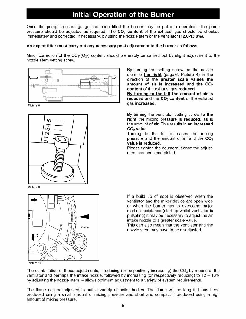
Once the pump pressure gauge has been fitted the burner may be put into operation. The pump pressure should be adjusted as required. The CO2 content of the exhaust gas should be checked immediately and corrected, if necessary, by using the nozzle stem or the ventilator (12.0-13.0%). An expert fitter must carry out any necessary post adjustment to the burner as follows:
Minor correction of the CO2-(O2-) content should preferably be carried out by slight adjustment to the nozzle stem setting screw.
- +- +
Picture 8
By turning the setting screw on the nozzle stem to the right (page 6, Picture 4) in the direction of the greater scale values the amount of air is increased and the CO2 content of the exhaust gas reduced. By turning to the left the amount of air is reduced and the CO2 content of the exhaust gas increased.
Picture 9
By turning the ventilator setting screw to the right the mixing pressure is reduced, as is the amount of air. This results in an increased CO2 value. Turning to the left increases the mixing pressure and the amount of air and the CO2 value is reduced. Please tighten the counternut once the adjust-ment has been completed.
Picture 10
If a build up of soot is observed when the ventilator and the mixer device are open wide or when the burner has to overcome major starting resistance (start-up whilst ventilator is pulsating) it may be necessary to adjust the air intake nozzle to a greater scale value. This can also mean that the ventilator and the nozzle stem may have to be re-adjusted.
The combination of these adjustments, - reducing (or respectively increasing) the CO2 by means of the ventilator and perhaps the intake nozzle, followed by increasing (or respectively reducing) to 12 – 13% by adjusting the nozzle stem, – allows optimum adjustment to a variety of system requirements. The flame can be adjusted to suit a variety of boiler bodies. The flame will be long if it has been produced using a small amount of mixing pressure and short and compact if produced using a high amount of mixing pressure.
Initial Operation of the Burner
Pinion

6
For SLV - B with Satronic burner safety control
� � � � � � � � � �
S3 NT2 T1 1B4
ϑ
bk
bk
br
bl
bl
Flame control
M~
Solenoid valve
Ignition transform
er
Motor
S3 NT2 T1 1B4
ϑ
N L
ϑ
Burner ContolSatronic
(Running time m
eter)
Lock out
Temperature regulator
(Therm
ostat)
Safety tempe-rature limiter
6 AOperation
Mainswitch
230 V ~ 50 Hz
- Multiple plug -
Burner side
System side
Oil preheater
Burner control- with preheater: TF 834.2 DKO 974 or DKW 976 for warm air heater- without preheater: TF 801.2 DKO 970 or DKW 972 for warm air heater
–––––––––––––––––––––––––––––––––––––––––––––––––––––––––––––––––––––––––––––––––––
For SLV - B with Landis & Gyr burner safety control
8 3 2 11 12 6 2 4 10 1 2Burner controlLandis & Gyr(Landis & Staefa)
S3 NT2 T1 1B4
ϑ
bk
bk
br
bl
bl
Flame control
M~
Solenoid valve
Ignition transform
er
Motor
S3 NT2 T1 1B4
ϑ
N L
ϑ
(Running time m
eter)
Lock out
Temperature regulator
(Therm
ostat)
Safety tempe-rature limiter
6 A
Operatio
n
Mainswitch
230 V ~ 50 Hz
- Multiple plug -
Burner side
System side
Oil preheater
Burner control LOA 24 or LOA 44 for warm air heater
Circuit Diagram
burner control type: Flame detector Type:
TF 834.2 MZ 770 S
TF 801.2 FZ 711 S
DKO 970 MZ 770 S
DKO 974 MZ 770 S
DKW 972 MZ 770 S
DKW 976 MZ 770 S

7
Problem: possible cause: solution:
burner motor will not start - no supply voltage
- safety thermostat locked
- nozzle stem oil pre-heater faulty
- control device faulty
- motor faulty
- oil pump tight
- replace fuse
- unlock
- replace
- replace
- replace
- clean or replace
burner starts up but switches to “fault” after expiry of safety period
- no ignition
- burner not being supplied with oil:
- oil tank empty
- dirty filters
- oil supply line leaking
- foot valve leaking
- oil supply line valves closed
- oil conveyor aggregate faulty
- burner oil pump faulty
- pump coupler faulty
- flame detector faulty or dirty
- outside light effecting flame detector
- nozzle dirty or faulty
- solenoid valve not opening
- ignition electrodes and adjustment,
- check ignition transformer and cable
- fill up oil tank
- replace
- seal
- clean
- open
- replace
- replace
- replace
- replace or clean
- locate light source
- replace
- replace coil or complete solenoid valve
Motor starts up burner but after c. 12 seconds burner switches to “fault”.
- solenoid valve not closing - replace valve tappet or complete solenoid valve
Flame goes out during operation - no oil left
- nozzle filters clogged
- oil filter or oil supply line dirty
- trapped air
- fill up with oil
- replace nozzle
- replace filter, clean supply line
- check suction pipe and armatures
Please note: Additional information on the Satronic System can be found on the last page.
Burner capacity [kW]
Pressure in the chamber [m
bar]
0
0,2
0,4
0,6
0,8
1,0
1,2
1,4
10 20 30 40 50 60 70 80
Type: SLV 10 B Nominal capacity range: 17 - 40 kW Oil flow rate: 1,4 - 3,4 kg/h Nominal voltage: 230 V / 50 Hz Nominal circuit: 240 W Fuel: Heating fuel oil EL
Type: SLV 22 B Nominal capacity range: 33 - 78 kW Oil flow rate: 2,8 - 6,6 kg/h Nominal voltage: 230 V / 50 Hz Nominal circuit: 290 W Fuel: Heating fuel oil EL
Technical Data, Capacity Diagram
Troubleshooting
8
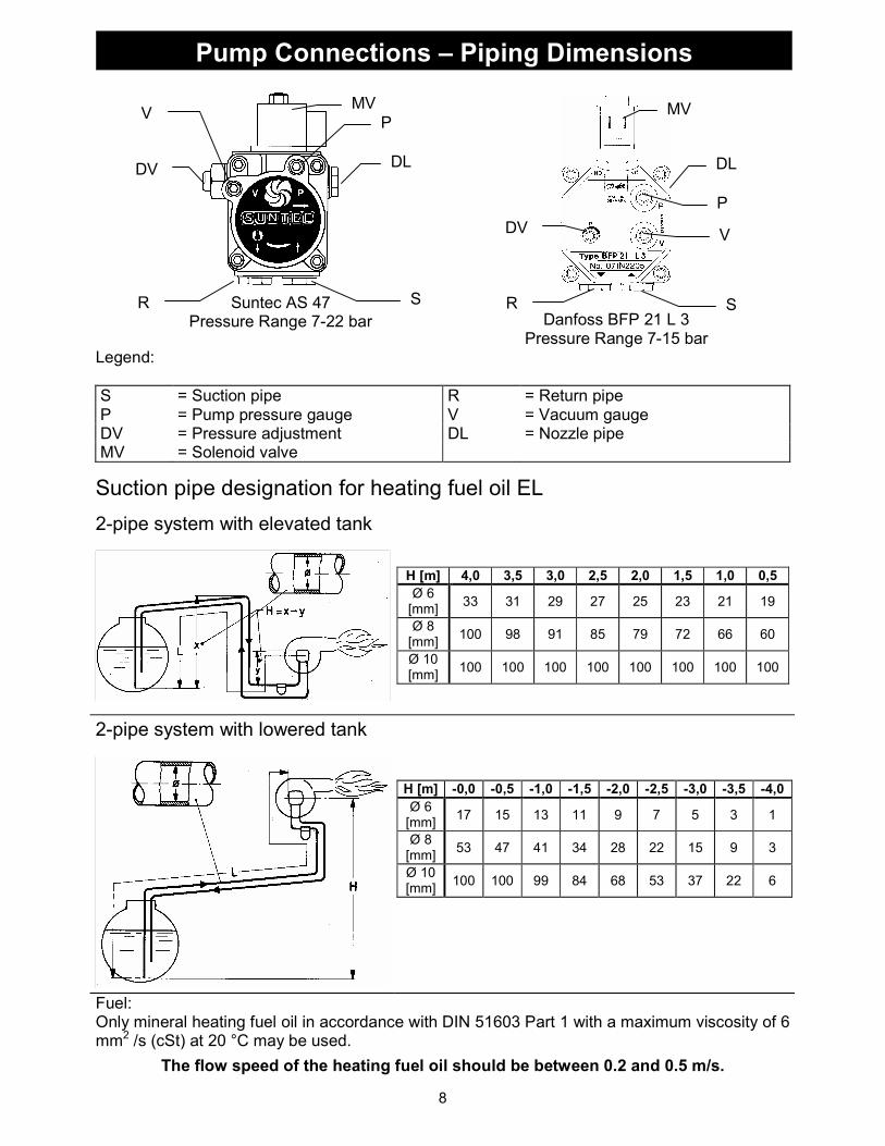
Suntec AS 47
Pressure Range 7-22 bar
Danfoss BFP 21 L 3 Pressure Range 7-15 bar
Legend:
S = Suction pipe R = Return pipe P = Pump pressure gauge V = Vacuum gauge DV = Pressure adjustment DL = Nozzle pipe MV = Solenoid valve
Suction pipe designation for heating fuel oil EL
2-pipe system with elevated tank
2-pipe system with lowered tank
Fuel: Only mineral heating fuel oil in accordance with DIN 51603 Part 1 with a maximum viscosity of 6 mm2 /s (cSt) at 20 °C may be used.
The flow speed of the heating fuel oil should be between 0.2 and 0.5 m/s.
Pump Connections – Piping Dimensions
H [m] 4,0 3,5 3,0 2,5 2,0 1,5 1,0 0,5
Ø 6 [mm]
33 31 29 27 25 23 21 19
Ø 8 [mm]
100 98 91 85 79 72 66 60
Ø 10 [mm]
100 100 100 100 100 100 100 100
H [m] -0,0 -0,5 -1,0 -1,5 -2,0 -2,5 -3,0 -3,5 -4,0
Ø 6 [mm]
17 15 13 11 9 7 5 3 1
Ø 8 [mm]
53 47 41 34 28 22 15 9 3
Ø 10 [mm]
100 100 99 84 68 53 37 22 6
P
V
R S
DV
MV
DL
P
V
R S
DV
MV
DL

9
Single pipe system with elevated tank
Single pipe system with lowered tank
Oil flow rate up to 2.5 kg/h
H [m] 4.0 3.5 3.0 2.5 2.0 1.5 1.0 0.5
Ø 4 [mm]
51 45 38 32 26 19 13 6
Ø 5 [mm]
100 100 94 78 62 47 31 16
Ø 6 [mm]
100 100 100 100 100 97 65 32
Oil flow rate up to 5.0 kg/h
H [m] 4.0 3.5 3.0 2.5 2.0 1.5 1.0 0.5
Ø 4 [mm]
26 22 19 16 13 10 6 3
Ø 5 [mm]
62 55 47 39 31 23 16 8
Ø 6 [mm]
100 100 97 81 65 49 32 16
Oil flow rate up to 10.0 kg/h
H [m] 4.0 3.5 3.0 2.5 2.0 1.5 1.0 0.5
Ø 5 [mm]
31 27 23 20 16 12 8 4
Ø 6 [mm]
65 57 49 40 32 24 16 8
Ø 8 [mm]
100 100 100 100 100 77 51 26
Oil flow rate up to 2.5 kg/h
H [m] -0.0 -0.5 -1.0 -1.5 -2.0 -2.5 -3.0 -3.5 -4.0
Ø 4 [mm]
52 46 40 33 27 21 15 9 2
Ø 5 [mm]
100 100 97 81 66 51 36 21 6
Ø 6 [mm]
100 100 100 100 100 100 75 44 12
Oil flow rate up to 5.0 kg/h
H [m] -0.0 -0.5 -1.0 -1.5 -2.0 -2.5 -3.0 -3.5 -4.0
Ø 4 [mm]
26 23 20 17 14 10 7 4 1
Ø 5 [mm]
63 56 48 41 33 26 18 11 3
Ø 6 [mm]
100 100 100 84 69 53 37 22 6
Oil flow rate up to 10.0 kg/h
H [m] -0.0 -0.5 -1.0 -1.5 -2.0 -2.5 -3.0 -3.5 -4.0
Ø 5 [mm]
32 28 24 20 17 13 9 5 1
Ø 6 [mm]
66 58 50 42 34 27 19 11 3
Ø 8 [mm]
100 100 100 100 100 84 59 35 10
Piping Dimensions

10
The Satronic DKO and DKW Burner Control Information System indicates the procedures in connection with the burner control unit and burner observation. It provides continuous information with regard to the programme phase currently governing the device. This communication is by means of a flash code. Special scanners such as PC, Laptop (Notebook), PalmPilot or SatroPen can be used to simplify communication.
Customer:
Heating Technician present:
Burner type: Man. No.:
Boiler manufactured by:
Type:
Heating capacity: kW Year built:
Measuring Report: 1st reading Measuring Report: 1
st reading
Manufacturer of nozzle Exhaust gas temperature °C
Size / Spray angle gph / ° Room temperature °C
Pump pressure bar Pressure at retarding disk hPa (mbar)
Flow kg/h Air at rear of boiler hPa (mbar)
CO2 % Pressure in body of boiler hPa (mbar)
O2 % Exhaust gas loss %
CO ppm Position of nozzle stem
NOX ppm Position of air intake nozzle
Soot
Date:
Signature of customer Signature of engineer
Initial Operation Protocol for Oil Burner
Handed over by:
Subject to technical alterations.
Flash Code of the Satronic Information System *)