maejo int. j. sci. technol. 2015 9(02), 209-223; doi: 10
TRANSCRIPT

Maejo Int. J. Sci. Technol. 2015, 9(02), 209-223; doi: 10.14456/mijst.2015.16
Maejo International Journal of Science and Technology
ISSN 1905-7873
Available online at www.mijst.mju.ac.th Full Paper
Three dimensional finite element analysis for preliminary establishment of tunnel influence zone subject to pile loading Prateep Lueprasert
1, Pornkasem Jongpradist 2, *, Kitcha Charoenpak
3, Pattanasak Chaipanna
4 and Suchatvee Suwansawat 1
1 Department of Civil Engineering, King Mongkut’s Institute of Technology Ladkrabang,
Ladkrabang District, Bangkok, Thailand 2 Department of Civil Engineering, Faculty of Engineering, King Mongkut’s University of
Technology Thonburi, Trungkru District, Bangkok, Thailand 3 Department of Highways, Ministry of Transport, Thailand 4 Department of Civil Engineering, Faculty of Industrial and Technology, Rajamangala University
of Technology Isan, Sakonnakhon Campus, Sakonnakhon, Thailand
* Corresponding author, e-mail: [email protected]
Received: 25 April 2014 / Accepted: 1 July 2015 / Published: 28 July 2015
Abstract: Urban development often involves the construction of infrastructures that require deep foundations or piles. Due to the existence of tunnels, the need to construct deep foundations in close proximity contributes to possible damage to the tunnels and operational safety concern. The concept of influence zones has been proposed as restrictive guidelines for construction adjacent to underground tunnels. However, the current influence zones are based on the conventional assumption of soil failure due to tunnelling rather than on an understanding of the pile-tunnel interaction. This paper thus analyses the impacts of piles under loading on the subway tunnel of the Mass Rapid Transit Authority of Thailand in Bangkok using the 3D finite element method. The analyses are carried out to investigate factors in tunnel deformations. The results show that the significant factors are the relative position of the pile tip with respect to the tunnel position as well as the soil type where the tunnel is located. In addition, this paper tentatively proposes a new influence zone for pile construction adjacent to the existing tunnel.
Keywords: tunnel influence zone, tunnel deformation, finite element method, pile foundation, tunnel distortion
________________________________________________________________________________

Maejo Int. J. Sci. Technol. 2015, 9(02), 209-223; doi: 10.14456/mijst.2015.16
210
INTRODUCTION Underground tunnelling is regarded as an effective means to overcome the problem of limited space in major cities. Underneath most metropolises are tunnels for transportation, water, electricity and gas. Generally, tunnels are lined underground along the major roads to avoid being under the buildings. Due to urbanisation and traffic congestion, more new infrastructures are constructed to meet the demands, e.g. flyovers, elevated trains and tall buildings, all of which require deep foundations. In several instances, the piles of these new structures are inevitably close to existing tunnels. Thus, the movement of the piles under loading would induce a certain degree of impact on the tunnels. An assessment of the impact of piles under loading on the stability and integrity of the tunnels is necessary. The assessment is typically carried out in two steps. The first step is to evaluate the potential impact of the pile foundation for a design modification of the pile position. At present, this is carried out by defining the influence zone of the tunnel in combination with certain criteria. An influence zone refers to an area of land where future developments or construction activities to be undertaken could result in the imposition of additional load on the tunnel structure or affect an operational system [1]. If the possible impact is serious, the second step of assessment is necessary, in which the design must be modified or a detailed assessment must be carried out.
Tunnel owners have used restrictive guidelines for new constructions adjacent to the tunnels. The guidelines could include one or more influence zones or a minimum clearance between structures, maximum allowable tunnel deformation, and stress changes in tunnel lining. Figure 1 illustrates tunnel influence zones for the new construction of the Land Transport Authority (LTA) [1] and the Mass Rapid Transit Authority (MRTA) [2]. An influence zone was conventionally assumed from the ideal shear plane from the model test first proposed by Morton and King [3]. The influence zone is thus assumed from the shear plane of the ground due to tunnelling, rather than from the impact of a new construction on the existing tunnel. The zone is applied to all construction types but is proved to be inappropriate for piles. In addition, the restrictive guidelines were established based on experiences rather than on the theoretical understanding of the pile-tunnel interaction. According to the load transfer mechanism of pile, only the soil surrounding the pile perimeter and at the pile tip moves. Thus, the tunnel influence zone subject to pile under loading should be smaller than that assumed by the shear failure plane. A better and more specific tunnel influence zone affected by nearby piles is therefore necessary for an efficient issuance of construction permits of pile-supported structures in an area near the existing tunnel. Several researches have attempted to understand the mechanisms of soil–tunnel–pile interactions. However, they mostly focused on the influence of tunnelling on nearby existing buildings and foundations, for examples the field observation [4], the full-scaled test [5], the physical modelling [6] and the numerical modelling [6-9]. With regard to the influence of nearby constructions on existing tunnels, there are few studies. Examples are the construction of a deep open excavation for an office block on the underlying tunnel complex in Prague-Czech Republic [10] and a multi-storey commercial building in Toronto [11].
Studies on the effects of pile loading on existing tunnels are even more limited even though the issue has been recognised since 1951 in London [12]. Schoroeder et al. [13] performed a numerical analysis on the interaction between pile rows supporting a 15-storey building and a tunnel. The study examined the influence of pile rows loading on the existing tunnel and the effects in terms of tunnel distortions and global movements in relation to the loading of bored piles in the

Maejo Int. J. Sci. Technol. 2015, 9(02), 209-223; doi: 10.14456/mijst.2015.16
211
vicinity. The analysis results were used to determine a specific clearance between the pile rows and the tunnel. However, the limitations of the study were that the soil was homogeneous, the pile length was identical, and the pile tip position was much lower than that of the tunnel. In some situations where the foundations of a bridge approach or small buildings are constructed adjacent to the tunnel, e.g. as shown in Figure 2, the position of pile tips is close to that of the tunnel.
Figure 1. Tunnel influence zone utilised in current practice
Figure 2. Pile foundations adjacent to existing tunnel Studies on the impact of construction of urban tunnels on adjacent existing pile foundations
indicate that the position of the pile tip in relation to the tunnel horizontal axis is the key issue of

Maejo Int. J. Sci. Technol. 2015, 9(02), 209-223; doi: 10.14456/mijst.2015.16
212
this problem [7, 14]. Recent research which numerically investigated the effect of pile loading adjacent to an existing tunnel also indicates that the clearance between the pile and the tunnel as well as the relative position between the pile tip and the tunnel is important [15]. Unlike the other previous studies, however, this study failed to investigate the effects of pile loading on the existing tunnel.
This present study numerically investigates the effects of the pile tip position in relation to the tunnel horizontal axis and of the nearby bored pile loading on the tunnel in multi-layer soil. The influence zone is then proposed. This research focuses on the Mass Rapid Transit (MRT) tunnel and on Bangkok subsoil. The analysis results in terms of tunnel deformations, i.e. changes of tunnel diameter in both vertical and horizontal directions, are presented. The evaluation of structural safety of the tunnel lining is, however, outside the scope of this research. ANALYSIS METHOD
The response of tunnel lining when subjected to pile loading, particularly in a single pile case, is principally a three-dimensional problem. The simulation of the effects of adjacent piles under loading on the tunnel was performed by means of a three-dimensional simulation using the finite element program ABAQUS [16].
The analysis consists of two categories: single pile and pile row under loading. The first category is to investigate the significance of pile tip position relative to the tunnel and of soil stratum in which the tunnel is located. The geometric parameters in the analysis are depicted in Figure 3. The existing tunnel diameter, DT, of 6.3 m and the depth, LT, of 20 m below the ground surface are fixed throughout the study. The position of the tip of the bored piles with the diameter of 1 m is varied over a range of 0.20-1.80 LT to investigate its impact. As shown in Figure 4, four cases of ground conditions in relation to the tunnel position are considered.
Figure 3. Illustration of piles under loading adjacent to an existing tunnel (DT = tunnel diameter; LT
= tunnel depth; LP = pile tip; CT = vertical distance from centre of tunnel to pile tip; H and V = tunnel deformations)
Based on the soil profiles along the tunnel alignment and from the tunnel transition part to
the ground level maintenance centre, the subsoil condition was varied to account for soft clay and

Maejo Int. J. Sci. Technol. 2015, 9(02), 209-223; doi: 10.14456/mijst.2015.16
213
stiff clay as shown in Figure 4. The piles were wished-in-place at the beginning of analysis. In the analysis the piles were loaded to their working load, which depends on the pile length and soil condition, using a safety factor of 2.5 of their ultimate capacity, which was calculated based on the alpha method [17]. From past experiences of a construction project in the UK, where the bored pile was successfully located at a distance of 3 m from the tunnel [18], a maximum clearance of 3.5 m (approximately 0.6 DT) is adopted in this study.
Figure 4. Soil profiles in this study Finite Element Mesh
The soil and piles were discretised into hexahedral (or brick) elements with a suitable aspect ratio. The shell elements were used to represent the tunnel lining. For the region of greater interest, finer discretisation mesh is used to obtain accurate solutions, especially in the tunnel lining and the zone between pile and tunnel. A tied interaction was assigned to the soil-pile and soil-lining interfaces to prevent the relative displacement of adjacent nodes on the interfaces.
Figure 5 shows examples of the analytical meshes for single-pile and pile-row problems. For the single-pile case, the dimension of the mesh is 50 m in the longitudinal direction, 60 m in the vertical direction and 80 m in the transverse direction. The mesh dimension of the pile row is similar to that of the single pile but with a thickness (in longitudinal direction) of 2.0 m. The pile is located on one side of the tunnel. Constitutive Model
The concrete bored pile and lining were assumed to be linearly elastic. The thickness of the lining is 0.30 m. The inner and outer diameters of the lining are thus 5.70 m and 6.30 m respectively. For the soil, several recently developed advanced models such as the hardening soil [19] can reproduce the behaviour of soil under loading with a higher degree of satisfaction. However, the Mohr-Coulomb model [16] is commonly used in current engineering practice due to its simplicity, with only five parameters being required. In this study the observed values for the determination of

Maejo Int. J. Sci. Technol. 2015, 9(02), 209-223; doi: 10.14456/mijst.2015.16
214
influence zone are the changes in tunnel diameter. Therefore, the Mohr-Coulomb model is considered appropriate. The model parameters can be readily obtained from the literature [20, 21]. The parameters used in the analysis, including lateral earth pressure ( 0k ), undrained and drained
Young's modulus ( uE , 'E ), undrained and drained shear strengths ( uC , 'C ), angle of friction ( ), unit weight of soil ( ), permeability (k) and specific gravity (GS), are garnered and listed in Tables 1 and 2. Note that the parameters for the hardening soil model for Bangkok subsoil can also be found in prior researches [e.g. 7, 22].
Figure 5. Finite element meshes for single-pile and pile-row cases
Table 1. Material properties of tunnel lining and bored pile [20]
Young modulus of concrete (E) (kN/m2)
Poisson’s ratio of concrete (ѵc) Unit weight of concrete (γc )
(kN/m3) 3.1 x 10⁷ 0.20 24
Table 2. Geotechnical design parameters in MRT Project [20, 21]
Soil stratum Material
model 0k uE 'E
Poisson’s
ratio uC 'C k GS
Weathered crust Elastic 0.60 13500 10800 0.33 - 5 25 18 0.08 2.70 Soft clay MC 0.75 6250 5000 0.33 20 5 20 16.5 0.0004 2.75 1st Stiff clay MC 0.85 66000 52800 0.33 120 5 26 20.5 0.0009 2.75 1st Dense sand MC 0.80 - 110000 0.25 - 0 36 20 0.08 2.65 2nd Stiff clay MC 0.80 82500 66000 0.30 120 5 26 20 0.0002 2.65 2nd Dense sand MC 0.80 - 150000 0.25 - 0 36 20 0.08 2.70
Note: MC = Mohr Coulomb; unit of uE , 'E , uC , 'C in kN/m2 , in kN/m3 and k in m/day k0 = lateral earth pressure; Eu and E’ = undrained and drained Young’s modulus; Cu and C’ = undrained and drained shear strengths; = angle of friction; γ = unit weight of soil; k = permeability; GS = specific gravity

Maejo Int. J. Sci. Technol. 2015, 9(02), 209-223; doi: 10.14456/mijst.2015.16
215
Analysis Conditions
In the initial condition, the initial distributions of vertical effective stress and horizontal effective stress were controlled by the given soil unit weights and the coefficient of earth pressure at rest, ko, for all strata. The bulk unit weight and ko of each soil layer were adopted from the MRT tunnel project [23].
The displacement boundary condition was for performing the simulation in this study. The side and bottom boundaries were sufficiently extended from the area of greatest change in the model to avoid the boundary effect and minimise significant impacts on the analysis results.
In the finite element model, the front and rear sides of the mesh were restrained against lateral movements but allowed for free vertical movement. Thus, no movement perpendicular to these sides was expected. Since the bottom of the mesh was fixed, there were no vertical and horizontal movements. These conditions were applied to all finite element meshes throughout the study.
Each analysis was performed in 2 stages. The first involved the construction of the tunnel, which was modelled by consecutively removing the soil elements situated in the excavation zone and activating the tunnel lining with simultaneous application of pressure on the tunnel face to stabilise the excavation face. The second stage was the application of the pile axial loading, which was the design working load to a wished-in-place concrete pile. The undrained analysis was considered. ANALYSIS RESULTS Single Pile
Figure 6 illustrates the changes in tunnel diameters in vertical and horizontal directions for the single-pile case with a clearance of 0.5 m. The changes in tunnel diameter are normalised by the tunnel diameter (DT) and plotted against the normalised depth of pile tip, LP/LT , for different cases (i.e. soil types). The normalised depth of tunnel position to tunnel diameter, CT/DT, is also provided in the y-axis on the right side. The negative and positive signs of magnitude in the x-axis denote a shortening and widening of the tunnel diameter respectively. It is clear from the Figure that, with identical clearance, the depth of the pile tip position relative to the tunnel has a strong influence on the tunnel deformations. The distribution patterns of changes in tunnel diameter in both vertical (V) and horizontal (H) directions are very similar for all analysis cases. The tunnel deformations become large when the pile tip is situated in the range of 2DT above and 2DT underneath the tunnel axis. Note that the pile in each case (with different length and soil profile) is loaded with different working load. However, the magnitude of tunnel deformation is extremely large for the tunnel in soft clay despite the smallest working load (for the same pile length), whereas it becomes small for the tunnel in stiff clay. The pile tip position that induces the maximum change in tunnel diameter is the point above the tunnel crown by 0.5-1DT. With regard to the pile tip position which induces the maximum tunnel deformation, it is found that this position is higher in stiffer soil than in softer soil. The maximum deformation occurs when the pile tip is embedded in the soft clay layer. The deformation rapidly decreases when the pile tip reaches the stiff clay layer underneath.

Maejo Int. J. Sci. Technol. 2015, 9(02), 209-223; doi: 10.14456/mijst.2015.16
216
Figure 6. Impact of pile tip position relative to the tunnel and in relation to soil profile on the change in tunnel diameter for single pile (clearance = 0.5 m)
The tunnel-pile interaction behaviour can be determined by interpreting the numerical
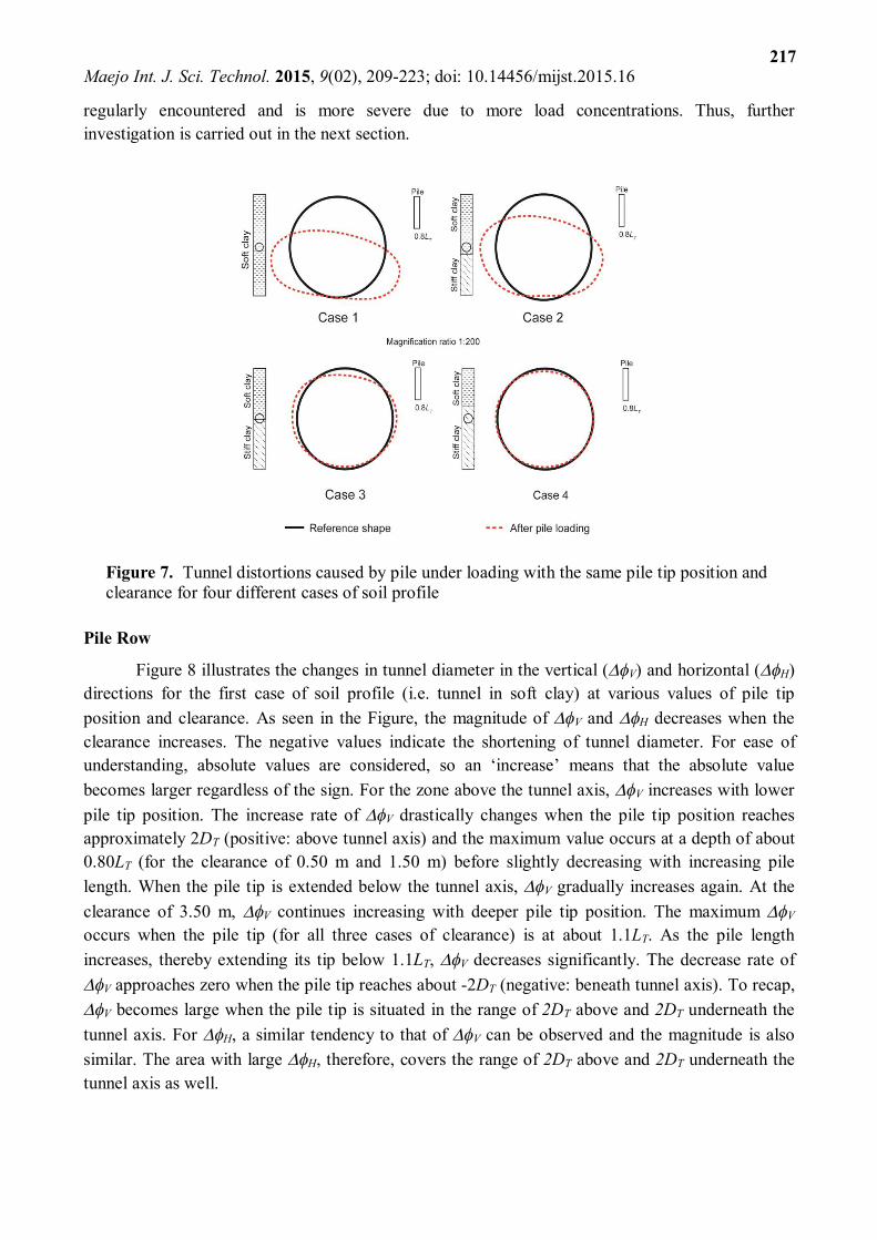
results. When a pile is loaded, the force is transmitted to the soil along the shaft and around the pile tip. This leads to an increase in stresses in soil. Simultaneously, the pile moves downward and causes the soil surrounding the pile to move. The soil movement interacts with the nearby existing tunnel and induces additional forces, stresses and displacements or distortion of the tunnel. The tunnel deformations by the pile tip located in soft clay are thus large due to large movements of the soil, as illustrated in Figure 7, which shows the distortion shapes by the same magnitude factor in the four cases of soil profile. The non-symmetric nature of the tunnel deformation can be observed. The tunnel diameter is reduced in the vertical direction and increased in the horizontal direction in all cases.
The preliminary results of this part confirm that the position of the pile tip relative to the tunnel and the soil type in which the tunnel is located have a significant impact on the tunnel deformation. In engineering practice the tunnel deformation induced by a pile row or pile group is
Maejo Int. J. Sci. Technol. 2015, 9(02), 209-223; doi: 10.14456/mijst.2015.16
217
regularly encountered and is more severe due to more load concentrations. Thus, further investigation is carried out in the next section.
Figure 7. Tunnel distortions caused by pile under loading with the same pile tip position and clearance for four different cases of soil profile
Pile Row
Figure 8 illustrates the changes in tunnel diameter in the vertical (V) and horizontal (H) directions for the first case of soil profile (i.e. tunnel in soft clay) at various values of pile tip position and clearance. As seen in the Figure, the magnitude of V and H decreases when the clearance increases. The negative values indicate the shortening of tunnel diameter. For ease of understanding, absolute values are considered, so an ‘increase’ means that the absolute value becomes larger regardless of the sign. For the zone above the tunnel axis, V increases with lower pile tip position. The increase rate of V drastically changes when the pile tip position reaches approximately 2DT (positive: above tunnel axis) and the maximum value occurs at a depth of about 0.80LT (for the clearance of 0.50 m and 1.50 m) before slightly decreasing with increasing pile length. When the pile tip is extended below the tunnel axis, V gradually increases again. At the clearance of 3.50 m, V continues increasing with deeper pile tip position. The maximum V occurs when the pile tip (for all three cases of clearance) is at about 1.1LT. As the pile length increases, thereby extending its tip below 1.1LT, V decreases significantly. The decrease rate of V approaches zero when the pile tip reaches about -2DT (negative: beneath tunnel axis). To recap, V becomes large when the pile tip is situated in the range of 2DT above and 2DT underneath the tunnel axis. For H, a similar tendency to that of V can be observed and the magnitude is also similar. The area with large H, therefore, covers the range of 2DT above and 2DT underneath the tunnel axis as well.

Maejo Int. J. Sci. Technol. 2015, 9(02), 209-223; doi: 10.14456/mijst.2015.16
218
Figure 8. Impact of pile tip position relative to tunnel axis on the changes in tunnel diameter for tunnel in soft clay layer (case 1, Figure 4)
Investigating the three other cases of soil profile reveals that both the trend and magnitude of V and H are almost identical to one another, so only V is shown for the three other cases. Figure 9 shows V as a function of pile tip position for the tunnel in case 2 (Figure 4). Generally, the results are similar to case 1, where the tunnel is in soft clay, although the maximum values are lower. Besides, the level of pile tip at which V rapidly decreases with increasing pile length is at the border between soft and stiff clays. Beneath this level, the rate of decrease for V becomes noticeable. This implies that the existence of stiff layer underneath the tunnel could account for smaller tunnel deformations and a narrower influence zone. The zone with large tunnel deformations appears to cover a range from 2DT above the tunnel axis to the border between soft and stiff clays, which is 0.5DT.

Maejo Int. J. Sci. Technol. 2015, 9(02), 209-223; doi: 10.14456/mijst.2015.16
219
Figure 9. Changes in tunnel diameter in vertical direction subject to pile row loading with various pile tip positions for tunnel in case 2 (Figure 4)
The results for tunnel located between soft clay and stiff clay layers (case 3, Figure 4) are
presented in Figure 10. The border between soft and stiff clays is set at the tunnel axis. For all three values of clearance, the values of V are smaller than those from the two previous cases. In comparison to the previous cases, the maximum values are significantly smaller and occur when the pile tip is in soft clay at a higher level. Similar to case 2, the level of pile tip at which V suddenly decreases with increasing pile length is at the border between soft and stiff clays. However, when the pile tip is extended below this level, which is stiff clay, V slightly increases again for a certain depth before it gradually decreases with increasing pile length. This is probably because at that depth the piles have a larger working load (due to end bearing capacity) and their tips are at the same level as the tunnel axis.
Figure 10. Changes in tunnel diameter in vertical direction subject to pile row loading with various pile tip positions for tunnel located between soft and stiff clays (case 3, Figure 4)

Maejo Int. J. Sci. Technol. 2015, 9(02), 209-223; doi: 10.14456/mijst.2015.16
220
Figure 11 depicts the results for the case of the tunnel constructed in stiff clay (case 4, Figure 4). The tunnel deformations as well as their maximum values are smallest among the four cases in this study. The tunnel in stiff soil is thus safer than that in soft soil due to smaller soil movements in the tunnel vicinity. The maximum values still occur when the pile tip is in soft clay even with a small working load. Therefore, caution should be exercised in the construction of the bearing unit pile adjacent to the tunnel. When the pile tip is near the tunnel in stiff clay, V increases again with a relatively higher value and longer range (compared to the previous case) after a large decrease at the clay border.
Figure 11. Changes in tunnel diameter in vertical direction due to pile row loading with various pile tip positions for tunnel in stiff clay layer (case 4, Figure 4)
The numerical results have confirmed that the deformations of an existing tunnel caused by a pile-row loading are similar to those caused by a single-pile loading, although the magnitude of the deformations in the former case is larger than in the latter. The deformations of the tunnel constructed in soft clay are much larger than in stiff clay and a large tunnel deformation occurs when the pile tip is close to the tunnel. The tunnel influence zone subject to nearby bored pile loading should therefore be determined by taking into account the relative position between the pile tip and the tunnel. The drastic changes of tunnel deformation are noticeable between about 2DT above and 2DT below the tunnel axis or down to the stiff layer, depending on the ground conditions, as listed in Table 3. For the horizontal clearance, a value of 0.6DT (approximately 3.5 m) from the tunnel surface seems to be sufficient. A new influence zone for the existing tunnel subject to nearby piles can then be proposed as shown in Figure 12. By comparison with the previously used influence zones, the developed zone obtained in this study (shaded rectangular area in Figure 12) is much smaller. This increases the likelihood of new construction projects in the area near the tunnel alignment. However, the proposed influence zone is specified based on one specific tunnel (i.e. that of the MRTA) and one pile size (1 m). A broader set of data is required to enhance its reliability.

Maejo Int. J. Sci. Technol. 2015, 9(02), 209-223; doi: 10.14456/mijst.2015.16
221
Table 3. Significant influence zone from pile-row analyses
Soil stratum Significant influence zone
Change of vertical diameter Change of horizontal diameter Case 1 2DT - (-2DT) 2DT - (-2DT) Case 2 2DT - (-0.5DT) 2DT - (-0.5DT) Case 3 2DT - (-1DT) 2DT - (-1DT) Case 4 2DT - (-1DT) 2DT - (-1DT)
Figure 12. Developed tunnel influence zone from nearby pile tip position
CONCLUSIONS
The position of pile tip in relation to the tunnel axis and the soil type in which the tunnel is situated have a significant impact on deformations of the existing tunnel. The numerically generated data and the consideration of the relative position of the pile tip can suggest a new influence zone.
The following observations have been made from the study: 1) The tunnel deformations become drastically large when the pile tip is situated in a specific range, depending on the soil type in which the tunnel is situated. However, the ranges for the four different soil types hardly alter. 2) It is reasonable to recommend the range of 2DT above and 2DT underneath the tunnel centre as the influence zone. 3) For the horizontal clearance, the value of 0.6DT from tunnel surface seems to be sufficient. 4) By considering the lining deformation induced by the movement of soil surrounding the pile, the proposed influence zone is much smaller than the existing zone in which all construction activities are taken into consideration. The smaller zone increases the possibility of new construction projects in the area near the tunnel alignment.

Maejo Int. J. Sci. Technol. 2015, 9(02), 209-223; doi: 10.14456/mijst.2015.16
222
However, as more complex behaviours in engineering practice are excluded from this study, future research that includes other relevant parameters, e.g. tunnel diameter, thickness of lining and pile size, is necessary for a more refined and more realistic tunnel influence zone. Moreover, further study on the correlation between pile settlement, pile force distribution and soil stress distribution around pile with lining deformation should enhance the understanding of this soil-structure interaction problem.
ACKNOWLEDGEMENTS
The financial support provided by the Office of the Higher Education Commission under the
Higher Education Research Promotion and National Research University (NRU) Project of Thailand is gratefully acknowledged. The first author would also like to extend his appreciation for the research funding from the Thailand Research Fund (TRF) and 1D2 Group Co. Ltd. under Grant PHD56I0057. REFERENCES 1. Land Transport Authority, “Code of Practice for Railway Protection”, Development and
Building Control Department, Singapore, 2004. 2. Mass Rapid Transit Authority of Thailand, “Restrictive Guideline for Protection Zone in Blue
Line Project”, Engineering Specifications for MRT Tunnels, Bangkok, 2009 (in Thai). 3. J. D. Morton and K. H. King, “Effects of tunneling on the bearing capacity and settlement of
piled foundation”, Proceedings of 2nd International Symposium on Tunnelling, 1979, London, Great Britain, pp.57-68.
4. R. J. Mair, R. N. Taylor and A. Bracegirdle, “Subsurface settlement profiles above tunnels in clays”, Geotechnique, 1993, 43, 315-320.
5. D. Selemetas, J. R. Standing and R. J. Mair, “The response of full-scale piles to tunneling”, Proceedings of 5th International Symposium TC28 on Geotechnical Aspects of Underground Construction in Soft Ground, 2005, Amsterdam, Netherlands, pp.763-769.
6. Y. J. Lee and R. H. Bassett, “Influence zones for 2D pile-soil-tunnelling interaction based on model test and numerical analysis”, Tunn. Undergr. Space Technol., 2007, 22, 325-342.
7. P. Jongpradist, T. Kaewsri, A. Sawatparnich, S. Suwansawat, S. Youwai, W. Kongkitkul and J. Sunitsakul, “Development of tunneling influence zones for adjacent pile foundations by numerical analyses”, Tunn. Undergr. Space Technol., 2013, 34, 96-109.
8. P. Kitiyodom, T. Matsumoto and K. Kawaguchi, “A simplified analysis method for piled raft foundations subjected to ground movements induced by tunnelling”, Int. J. Numer. Anal. Meth. Geomech., 2005, 29, 1485-1507.
9. H. Y. Liu, J. C. Small and J. P. Carter, “Full 3D modelling for effects of tunnelling on existing support systems in the Sydney region” Tunn. Undergr. Space Technol., 2008, 23, 399-420.
10. M. Dolezalova, “Tunnel complex unloaded by a deep excavation”, Comput. Geotech., 2001, 28, 469-493.
11. M. Abdel-Meguid, R. K. Rowe and K. Y. Lo, “3D effects of surface construction over existing subway tunnels”, Int. J. Geomech., 2002, 2, 447-469.
12. E. O. Measor and D. H. New, “The design and construction of the Royal Festival Hall, South Bank”, J. Inst. Civil Eng., 1951, 36, 241-305.
13. F. C. Schroeder, D. M. Potts and T. I. Addenbrooke, “The influence of pile group loading on existing tunnels”, Geotechnique, 2004, 54, 351-362.
Maejo Int. J. Sci. Technol. 2015, 9(02), 209-223; doi: 10.14456/mijst.2015.16
223
14. H. Mroueh and I. Shahrour, “Three-dimensional finite element analysis of the interaction between tunneling and pile foundations”, Int. J. Numer. Anal. Meth. Geomech., 2002, 26, 217-230.
15. S. Arunkumar and R. Ayothiraman, “Effect of vertically loaded pile on existing urban tunnel in clay”, Proceedings of Indian Geotechnical Conference, 2010, Mumbai, India, pp.751-754.
16. Simulia, “ABAQUS Analysis User's Manual, Version 6.3-1”, Dassault Systèmes Simulia Corp, Providence (RI), 2008.
17. A. W. Skempton, “Cast in-situ bored piles in London Clay”, Geotechnique, 1959, 9, 153-173. 18. I. Chudleigh, K. G. Higgins, H. D. St John, D. M. Pott and F. C. Schroeder, “Pile-tunnel
interaction problems”, Proceedings of Tunnel Construction and Piling, 1999, London, Great Britain, pp.172-185.
19. T. Schanz, P. A. Vermeer and P. G. Bonnier, “The hardening soil model: Formulation and verification”, Proceedings of PLAXIS symposium on “Beyond 2000 in Computational Geotechnics”, 1999, Rotterdam, Netherlands, pp.281-296.
20. S. Timpong, “Analysis of ground movements in Bangkok MRT Blue Line project”, Master Thesis, 2002, Asian Institute of Technology, Thailand.
21. C. T. Tseng, “Three dimension simulation of EPB shield tunneling in Bangkok soft ground”, Master Thesis, 2000, Asian Institute of Technology, Thailand.
22. C. Surasak, S. Likitlersuang, D. Wanatowski, A. Balasubramanim, E. Oh and H. Guan, “Stiffness and strength parameters for hardening soil model of soft and stiff Bangkok clays”, Soils Found., 2012, 52, 682-697.
23. R. E. Prust, J. Davies and S. Hu, “Pressuremeter Investigation for Mass Rapid Transit in Bangkok, Thailand”, Transport. Res. Rec. J. Transport. Res. Board, 2005, 1928, 207-217.
© 2015 by Maejo University, San Sai, Chiang Mai, 50290 Thailand. Reproduction is permitted for noncommercial purposes.