magact pm actuator - ipec eng©pm actuator electronic controllers ... iec 255-5 - 1977 vibration and...
TRANSCRIPT
Weight 366g www.ipeceng.com
"SCIENCE AND TECHNOLOGY IN POWER ENGINEERING"
MAGACT© PM ACTUATOR ELECTRONIC CONTROLLERS
IPEC ENGINEERING MAGACT©
controllers utilise robust and reliable,military specification FieldProgrammable Gate Array (FPGA)technology with all intelligent controllogic and strategy softwareprogrammed. Sophisticated multi-layer PCBs are utilised alongsidecomplete opto-isolation for acompact system with outstandingEMC immunity. The output currentpulse timing from the controller canbe easily hardware programmedaccording to the controlrequirements of the VCB offering anextremely flexible solution to thecustomer.
IPEC ENGINEERING holdssubstantial expertise and experiencein the design of high qualityElectronic Controllers to providecontrol, drive and monitoring ofPermanent Magnet (PM) Actuatorsto drive Medium Voltage VCBs.IPEC ENGINEERING is one of onlya few companies in the world whocan combine actuator design,electronic drives and advancedmicrocontroller technology to provide‘holistic’ solutions for the newgeneration of PM Actuator VCBs.
Introduction
Technology
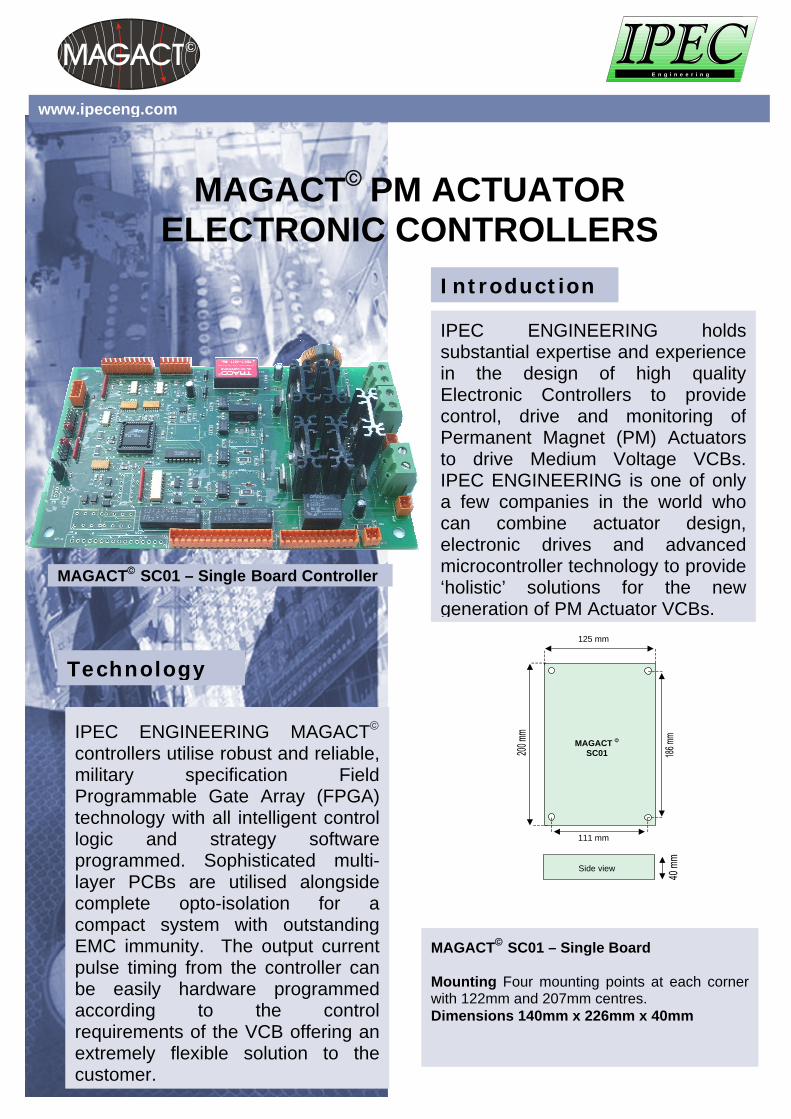
MAGACT© SC01 – Single Board Controller
MAGACT ©
SC01
Side view
125 mm
111 mm
MAGACT© SC01 – Single Board Mounting Four mounting points at each cornerwith 122mm and 207mm centres. Dimensions 140mm x 226mm x 40mm
E n g i n e e r i n g

www.ipeceng.com
• All Controller inputs and outputs
are opto-isolated to provideexcellent EMC immunity andreliability.
• Military-Specification FPGA
(Field Programmable GateArray) technology is at the coreof the controller which ensuresreliability of operation in harshenvironments and a widefrequency range.
• Universal voltage supply range
from 12 to 300 Vac or dcdepending on the customer’s orthe installation requirements.
• Variable Close Pulse, Trip Pulse
and Trip Pulse Delay timingwhich is fully hardwareprogrammable and suitable forall single-coil PM Actuatordesigns.
• Intelligent 'closed loop' control
and switching of the coil currentminimises energy consumptionand ensures reliable O-COoperation – refer to Figures 1and 2.
• Coil current is precisely
controlled using high qualityMOSFETS ensuring a controllerworking life of a minimum of500,000 operations.
IPEC ENGINEERING MAGACT©
PM Actuator ElectronicController Features:
Actuator travel
Coil current
Coil current 'cutoff' after actuatoroperationcompleted
Coil currentcontinues to a pre -set time, wastingenergy
Coil current
Actuator travel
Technical Discussion: Figure 1 shows the operation of a PMactuator using IPEC ENGINEERING’sIntelligent MAGACT© Electronic Controllerwith ‘Closed Loop’ Control. In this case thecontroller is programmed to emit the coilcurrent pulse until a positive signal isreceived back from the microswitch positionindicators (in this case the contacts ‘closed’indicator). This ensures successful operationof the actuator in situations such as rapidreclose operations whilst maintainingmaximum efficiency. This provides theopportunity for a smaller, more cost effectiveelectrolytic capacitor bank. Figure 2 shows the operation of the samePM actuator using a standard electroniccontroller. This shows that any currentflowing after the end of actuator operation iswasted energy. If the current pulse durationis reduced with such a controller (to try tosave energy) reliable sequential operationover the life of the VCB cannot be ensured.This is particularly true when contact wear inthe VI and mechanical wear of themechanical drive results in changes in theoperating time of the VCB after extended
Figure 1. Close Operation of a PM Actuator usingthe MAGACT© Intelligent Electronic Controllerwith ‘Closed Loop’ Control (Note that coil currentis switched off 10ms after VI Contacts closure)
Figure 2. Close Operation of a PM Actuatorwithout Closed Loop Control (Note that coilcurrent is not switched off after VI Contactsclosure with subsequent energy wastage)
www.magact.comwww.ipeceng.com
IP E CE le c tro n icA c tu a to r
C o n tro lle r
D C /D CC o n ve rte r
+
B a tte ry
-
C o n tro lIn p u ts
C o n tro l O u tp u ts
C lo se / tr ip
S en so r
S en so r
C a p a c ito r
C lo s e
O p e n
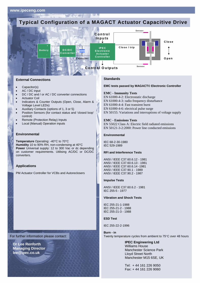
Typical Configuration of a MAGACT Actuator Capacitive Drive
External Connections • Capacitor(s) • AC / DC input • DC / DC and / or AC / DC converter connections • Actuator Coil • Indicators & Counter Outputs (Open, Close, Alarm &
Voltage Level LEDs) • Auxiliary Contacts (options of 1, 3 or 5) • Position Sensors (for contact status and ‘closed loop’
control) • Remote (Protection Relay) Inputs • Local (Manual) Operation inputs Environmental Temperature Operating: -40°C to 70°C Humidity 10 to 90% RH, non-condensing at 40°C Power Universal supply: 12 to 300 Vac or dc dependingon customer requirements. Utilising AC/DC or DC/DCconverters. Applications PM Actuator Controller for VCBs and Autoreclosers
Standards EMC tests passed by MAGACT© Electronic Controller EMC - Immunity Tests EN 61000-4-2: Electrostatic discharge EN 61000-4-3: radio frequency disturbance EN 61000-4-4: Fast transient burst EN 61000-4-6: electrical pulse surge EN 50155: Variations and interruptions of voltage supply EMC - Emissions Tests EN 55022 Class A: Electric field radiated emissions EN 50121-3-2:2000: Power line conducted emissions Environmental IEC 68-2-30-1980 IEC 529-1989 RFI and Interference Tests ANSI / IEEE C37.60.6.12 - 1981 ANSI / IEEE C37.60.6.13 - 1981 ANSI / IEEE C37.60.6.14 -1981 ANSI / IEEE C37.90.1 - 1989 ANSI / IEEE C37.90.2 - 1987 Impulse Tests ANSI / IEEE C37.60.6.2 - 1981 IEC 255-5 - 1977 Vibration and Shock Tests IEC 255-21-1-1988 IEC 255-21-2 - 1988 IEC 255-21-3 - 1988 ESD Test IEC 255-22-2-1996 Burn - in Twenty temperature cycles from ambient to 75°C over 48 hours
Dr Lee Renforth Managing Director [email protected]
IPEC Engineering Ltd Williams House Manchester Science Park Lloyd Street North Manchester M15 6SE, UK Tel: + 44 161 226 9050 Fax: + 44 161 226 9060
For further information please contact: