magna-loc install guide
TRANSCRIPT

Magna-Loc Install Guide
800-728-4010bestbuymetals.com
IMPORTANT INFORMATIONThe application and detail drawings in this manual are strictly for illustration purposes and may not be applicable to all building designs orproduct installations. All projects should conform to applicable building codes for that particular area. It is recommended to follow allbuilding regulations and standard industry practices.
We cannot be responsible for the performance of the roof system if it is not installed in accordance with the suggested instructionsreferenced in this manual. If there is a conflict between this manual and the approved erection drawings, the approved erection drawingsare to take precedence.
Prior to ordering and installing materials, all dimensions should be verified by field measurements.
Oil canning is not a cause for rejection. Oil canning can be described as the amount of waviness found in the flat areas of metal panels.Oil canning is an inherent characteristic of light gauge cold formed metal products, particularly those with broad flat areas. There are manyfactors which may contribute to oil canning that the plant is not able to control. These factors include: misalignment of the support system,over driving of fasteners used on the panels, stress (whether inherent in the panel or induced), thermal expansion and contraction of thepanel, material handling, width, gauge, length, color of panels, and installation. (Reference Metal Construction Association "Oil CanningPosition Paper" - Appendix A).
We reserve the right to modify, without notice, any details, recommendations or suggestions. Any questions you may have regarding properinstallation of the Magna-Loc roofing system should be directed to your representative.
Consult your representative for any additional information not outlined in this manual.
This manual is designed to be utilized as a guide when installing the Magna-Loc roofing system. It is the responsibility of the erector toensure the safe installation of this product system.
SAFETYSTUDY APPLICABLE OSHA AND OTHER SAFETY REQUIREMENTS BEFORE FOLLOWING THESE INSTRUCTIONS.
The installation of metal roof systems is a dangerous procedure and should be supervised by trained knowledgeable erectors. USEEXTREME CARE WHILE INSTALLING ROOF PANELS. It is not possible for us to be aware of all the possible job site situations that couldcause an unsafe condition to exist. The erector of the roof system is responsible for reading these instructions and determining the safestway to install the roof system.
These instructions are provided only as a guide to show a knowledgeable, trained erector the correct parts placement one to another. Iffollowing any of the installation steps would endanger a worker, the erector should stop work and decide upon a corrective action.
Provide required safety railing, netting, or safety lines for crew members working on the roof.
Do not use the roof panel as a walking platform. The roof panels will not withstand the weight of a person standing at the edge of the panel.
Do not stand on any part of a roof panel until the panel has been completly attached.

2
MAGNA-LOC
We offer a complete line of metal roof, wall, and fascia panel systems for the commercial, architectural, industrial, residential, and agricultural markets. We offer over 75 profiles with a wide selection of widths, colors, and gauges - new construction or retrofit.
M
M M
Manufactures Magna-Loc Panels
MANUFACTURING BRANCHES
M
M
M
Materials may be delivered, shipped direct, or in many cases transferred to a nearby plant for delivery.
M

3
CUSTOMER SERVICE
Best Buy Metals National Sales
1652 S Lee HwyCleveland, TN 37311
800-728-4010

4
MAGNA-LOCPAGE NO.General Information
Important Information ......................................................................................................... 1Mfg Locations ..................................................................................................................... 2Customer Service ............................................................................................................... 3Table of Contents .........................................................................................................4 & 5
Color Codes ..................................................................................................................... 6Flashing Angle Chart ...................................................................................................... 7Panel Profiles
90° Panel Profiles ................................................................................................. 8 180° Panel Profiles ............................................................................................... 9 180° Curved Panel Profiles ................................................................................ 10Accessory Profiles .................................................................................................. 11-14Flashing Profiles ...................................................................................................... 15-21Fastener Selection Guide ............................................................................................. 22Fastener Technical Information
Physical Properties ............................................................................................. 23Pull Out Strength Values .................................................................................... 24Pull Over Strength Values .................................................................................. 25
UL 580 Wind Uplift Information ............................................................................... 26-30UL 263 Fire Resistance Rating ..................................................................................... 30Section Properties and Load Tables ............................................................................ 31Handling Material
Receiving Material ............................................................................................................ 32General Handling ............................................................................................................. 32Mechanical Handling ........................................................................................................ 32Manual Handling .............................................................................................................. 33
StorageGeneral ............................................................................................................................ 34Storage on Roof ............................................................................................................... 35
Foot Traffic ................................................................................................................... 36Field Cutting and Touch-up
Field Cutting ..................................................................................................................... 37Touch-up Paint ................................................................................................................. 37
Design / Installation ConsiderationsFastener Installation Technique ........................................................................................ 38Condition of Substructure ................................................................................................. 38Ventilation ........................................................................................................................ 39Insulation .......................................................................................................................... 39System Expansion / Contraction ..................................................................................... 40Selection of System Components ................................................................................... 40Factory Notching and Prepunching ................................................................................... 41
Installation Procedure Overview ................................................................................. 42Installation of Panel
Installation of Floating Rake Zee ...................................................................................... 43Installation of Eave Plate .................................................................................................. 44Installing First Panel ......................................................................................................... 45Installing Panel Clips ......................................................................................................... 46Endlapping of Panel .....................................................................................................47-48Sidelapping of Panel ....................................................................................................49-50Termination of Panel ........................................................................................................ 51Seaming Panels ..........................................................................................................52-53
Installation of Panel Over Open FramingSculptured Eave .............................................................................................................. 54Sculptured Gutter ............................................................................................................. 554.5" Drop Valley ................................................................................................................ 569" Drop Valley ...................................................................................................................57Endlap ..............................................................................................................................58SSR Sculptured Rake (On Module) .................................................................................59SSR Sculptured Rake (Off Module) .................................................................................60
TABLE OF CONTENTS

5
PAGE NO.
TABLE OF CONTENTS (cont.)
Installation of Panel Over Open Framing (cont.)Rakewall (On Module) ......................................................................................................61Rakewall (Off Module) ......................................................................................................62Expansion Joint ................................................................................................................63Pitch Break With Wall Panel ............................................................................................64Sculptured High Side Eave ..............................................................................................65SSR Ridge .......................................................................................................................66Ridge / Hip .......................................................................................................................67Vented Ridge ....................................................................................................................68
Installation of Panel Over DeckingEave Offset ......................................................................................................................69Box Gutter Offset .............................................................................................................70Valley Offset ......................................................................................................................71Rake (On Module) ............................................................................................................72Rake (Off Module) ............................................................................................................73Rakewall ...........................................................................................................................74Peak .................................................................................................................................75Ridge / Hip - Fixed ...........................................................................................................76Vented Ridge ....................................................................................................................77
Installation of End Dam ................................................................................................ 78Installation of Z-Closures ............................................................................................ 79Clip Detail ...................................................................................................................... 80Transition Detail ............................................................................................................ 81Hemming Detail ............................................................................................................ 82Roof Penetrations
General Notes ................................................................................................................... 83Installation Notes............................................................................................................... 83
Care and Maintenance ................................................................................................. 84 Notes ............................................................................................................................ 85

MAGNA-LOC COLOR CODES
When placing an order, be sure to include the description of the product being ordered along with its product number All product numbers consist of a minimum of seven (7) digits. You will notice throughout our price book that some parts have a seven (7) digit number and others have five (5) digits with two blanks. These two blanks are to be filled in with a designated color code (see below for color codes). See Color Guides for color and gauge selections.
For example: Magna-Loe Product Number 2835273 means this part is designated to be color code 73 (Patriot Red).
PVDF
I I I (Kynar 500®) Color SR TE SRI
Aged Copper (65) 0.32
Antique Patina (M1) 0.38
Ash Grey (25) 0.38
Brandywine (P8) 0.26
Champagne Metallic (168) 0.47
Classic Green (66) 0.32
Colonial Red (W75) 0.35
Copper Penny (W92) 0.45
Dark Bronze (50) 0.30
Felt Green (W66) 0.31
Galvalume (41) 0.67
Hemlock Green (M7) 0.36
Khaki (88) 0.35
Linen White (81) 0.73
Mansard Brown (133) 0.30
Matte Black (106) 0.27
Medium Bronze (H4) 0.30
SR = Solar Reflectance
TE = Thermal Emittance
SRI = Solar Reflectance Index
Solar ReRectom:e: tbs frndioo ol lllllW etlel!JI' illot is reRecred by ri1e 1ool
0.85
0.85
0.86
0.85
0.85
0.86
0.86
0.85
0.86
0.84
0.14
0.85
0.87
0.86
0.87
0.86
0.87
Thermal Emittan<e: the,� � �iUljtol
1he 1ool wrfoce ro 11111ilte l!Wlibed lient
32
40
41
24
53
33
37
50
30
31
56
38
37
89
31
26
31
PVDF
I(Kynar 500®) Color SR I TE I SRI
Metallic Silver (K7) 0.60 0.77 68
Mistique Plus (W31) 0.34 0.82 34
Ocean Blue (35) 0.29 0.86 29
Old Town Grey (W25) 0.40 0.85 43
Old Zinc Grey (W29) 0.42 0.85 46
Parchment (W7 4) 0.41 0.86 45
Patina Green (W58) 0.46 0.85 51
Patriot Red (73) 0.46 0.86 52
Regal Blue (W35) 0.27 0.86 26
River Teal (59) 0.29 0.86 29
Sandstone (W51) 0.54 0.86 63
Slate Grey (W38) 0.30 0.85 30
Snowdrift White (W81) 0.65 0.85 78
Tahoe Blue (W71) 0.30 0.86 30
Taupe (74) 0.29 0.84 28
Terra Cotta (W72) 0.39 0.85 42
Weathered Copper (W50) 0.32 0.84 32
Some lleoJ is ollse1bed by lhe rool ll!lll llllBSlerred to lhe D!Jllding below -•• , 1/. . ' . .
All Colors meet or exceed Steep Slope ENERGY STAR Requirements

7
FLASHING ANGLE CHART
PROFILE/FLASHING 1/4":12 1/2":12 1:12 2:12 3:12 4:12 5:12 6:12 7:12 8:12
RIDGESSR RIDGEVENTED RIDGE COVER
178° 175° 170° 161° 152° 143° *135° *127° *120° *113°
HIPVALLEY 178° 177° 173° 167° 160° 154° 148° 143° 138° 134°
EAVEEXTENDED EAVESCULPTURED EAVE
91° 92° 95° 99° 104° 108° 113° 117° 120° 124°
SSR SCULPTUREDHIGH SIDE EAVE 99° 98° 95° 91° 86° 82° *77° *73° *70° *66°
PEAK 89° 88° 85° 81° 76° 72° 67° 63° 60° 56°
PITCH BREAKHIGH SIDE PITCH BREAK 91° 92° 95° 99° 104° 108° 113° 117° 120° 124°
GUTTER DRIPBOX GUTTER 91° 92° 95° 99° 104° 108° 113° 117° 120° 124°
SSR SCULPTURED GUTTER A 101° 102° 105° 109° 114° 118° 123° 127° 130° 134°
B 89° 88° 85° 81° 76° 72° 67° 63° 60° 56°PROFILE RIB HT.
MAGNA-LOC 2" C 55/8" 53/4" 6" 61/2" 7" 71/2" 8" 81/2" 9" 91/2"
This chart should be used to determine the specified angle.
*Note: Standard flashing dimensions may not accommodate all situations, please inquire about custom flashings with slopes 6:12 or greater.
A
CB
4"
4"

8
MAGNA-LOC
_ _ Represents color code designation. See page 6 in this manual or color guides for color selection. Requires additional lead time.
ACG (Flat) 24 16" 2735141 130 ACG (Striated) 24 16" 2735241 130 ACG (Pencil Rib) 24 16" 2785041 130
PVDF Standard(Flat) 24 16" 28351_ _ 130 PVDF Standard(Striated) 24 16" 28352_ _ 130 PVDF Standard(Pencil Rib) 24 16" 28850_ _ 130
ACG (Flat) 22 16" 2935141 161 ACG (Striated) 22 16" 2935241 161 ACG (Pencil Rib) 22 16" 2985041 161
PVDF (Flat) 22 16" 30351_ _ 161 PVDF (Striated) 22 16" 30352_ _ 161 PVDF (Pencil Rib) 22 16" 30850_ _ 161
ACG (Flat) 24 18" 2735341 126 ACG (Striated) 24 18" 2735441 126 ACG (Pencil Ribs) 24 18" 2785241 126
PVDF Standard(Flat) 24 18" 28353_ _ 126 PVDF Standard(Striated) 24 18" 28354_ _ 126 PVDF Standard(Pencil Ribs) 24 18" 28852_ _ 126
ACG (Flat) 22 18" 2935341 156 ACG (Striated) 22 18" 2935441 156 ACG (Pencil Ribs) 22 18" 2985241 156
PVDF (Flat) 22 18" 30353_ _ 156 PVDF (Striated) 22 18" 30354_ _ 156 PVDF (Pencil Ribs) 22 18" 30852_ _ 156
FINISH GAUGE COVERAGE PRODUCT NO. WT/SQ
C
Factory Applied Sealant
Panel Coverage (Flat)
2"
2"
Factory Applied Sealant
Panel Coverage (Striated)
C C 2"
Factory Applied Sealant
6" 6" 6"Panel Coverage (Pencil Ribs)
Sellersburg and Fontana Branches Only
90o Seam
90° PANEL PROFILE
PANEL NOTES1. For panel lengths over 45'-0", please inquire.2. Minimum recommended roof slope: 1/2:12.3. All panels have factory applied sealant.4. Oil canning is not a cause for rejection. Heavier gauges help minimize oil canning.5. The Magna-Loc panel system requires the use of a mechanical seamer for proper installation. Contact your rep for rental
information.6. If requested, panels are factory notched and/or pre-punched for endlap conditions.7. Finish: PVDF (Meets Kynar 500/Hylar 5000 Specs).8. For additional information on product applications, loadings and flashing details, consult the Product or Installation
Manuals.

9
MAGNA-LOC
4"
C 2"
Factory Applied Sealant
6"6"
Factory Applied Sealant
16" Coverage (Flat)
2"C
16" Coverage (Striated)
Factory Applied Sealant
2"C
16" Coverage (Pencil Ribs)Sellersburg and Fontana Branches Only
180o Seam
_ _ Represents color code designation. See page 6 in this manual or color guides for color selection. Requires additional lead time.
ACG (Flat) 24 16" 2735741 130 ACG (Striated) 24 16" 2735841 130 ACG (Pencil Rib) 24 16" 2735541 130
PVDF Standard(Flat) 24 16" 28357_ _ 130 PVDF Standard(Striated) 24 16" 28358_ _ 130 PVDF Standard(Pencil Rib) 24 16" 28355_ _ 130
ACG (Flat) 22 16" 2935741 161 ACG (Striated) 22 16" 2935841 161 ACG (Pencil Rib) 22 16" 2935541 161
PVDF (Flat) 22 16" 30357_ _ 161 PVDF (Striated) 22 16" 30358_ _ 161 PVDF (Pencil Rib) 22 16" 30355_ _ 161
ACG (Flat) 24 18" 2735941 126 ACG (Striated) 24 18" 2736041 126 ACG (Pencil Rib) 24 18" 2735641 126
PVDF Standard(Flat) 24 18" 28359_ _ 126 PVDF Standard(Striated) 24 18" 28360_ _ 126 PVDF Standard(Pencil Rib) 24 18" 28356_ _ 126
ACG (Flat) 22 18" 2935941 156 ACG (Striated) 22 18" 2936041 156 ACG (Pencil Rib) 22 18" 2935641 156
PVDF (Flat) 22 18" 30359_ _ 156 PVDF (Striated) 22 18" 30360_ _ 156 PVDF (Pencil Rib) 22 18" 30356_ _ 156
FINISH GAUGE COVERAGE PRODUCT NO. WT/SQ
PANEL NOTES1. For panel lengths over 45'-0", please inquire.2. Minimum recommended roof slope: 1/2:12.3. All panels have factory applied sealant.4. Oil canning is not a cause for rejection. Heavier gauges help minimize oil canning.5. The Magna-Loc panel system requires the use of a mechanical seamer for proper installation. Contact your rep for rental
information.6. If requested, panels are factory notched and/or pre-punched for endlap conditions.7. Finish: PVDF (Meets Kynar 500/Hylar 5000 Specs).8. For additional information on product applications, loadings and flashing details, consult the Product or Installation
Manuals.
180° PANEL PROFILE

10
MAGNA-LOC
Panel Coverage (Striated)
2"C
180o Seam
_ _ Represents color code designation. See page 6 in this manual or color guides for color selection. Requires additional lead time.* Additional charges for Field Bending and for Factory Bending
ACG (Striated) 24 16" 3135841 130
PVDF Standard(Striated) 24 16" 32358_ _ 130
ACG (Striated) 24 16" 3335841 161
PVDF (Striated) 22 16" 34358_ _ 161
ACG (Striated) 24 18" 3536041 126
PVDF Standard(Striated) 24 18" 37360_ _ 126
ACG (Striated) 22 18" 3836041 156
PVDF (Striated) 22 18" 39360_ _ 156
FINISH GAUGE COVERAGE PRODUCT NO. WT/SQ
180° CURVED PANEL PROFILE
PANEL NOTES1. For panel lengths over 45'-0", please inquire.2. Minimum curve radius is 20'.3. All panels have factory applied sealant. The sealant is applied as part of the curving operation.4. Oil canning is not a cause for rejection. Heavier gauges help minimize oil canning.5. The Magna-Loc panel system requires the use of a mechanical seamer for proper installation. Contact your rep for rental
information.6. If requested, panels are factory notched and/or pre-punched for endlap conditions.7. Finish: PVDF (Meets Kynar 500/Hylar 5000 Specs).8. For additional information on product applications, loadings and flashing details, consult the Product or Installation
Manuals.9. Add 30 feet of extra sheets for fine tuning curving machine per radius, per job.
Factory Applied Sealant

11
MAGNA-LOC ACCESSORY PROFILESMAGNA-LOC CLIP
(FLOATING) 23/8" Low (Floating) 4923302 50 pieces 12.50 lbs
33/8" High (Floating) 4923303 50 pieces 15.50 lbs
*21/8" Utility (Fixed) 4923321 50 pieces 6.00 lbs
23/8" Low (Fixed) 4923322 50 pieces 7.00 lbs
MAGNA-LOC CLIP(FIXED)
*Pancake Head fasteners to be used with fixed clips.
2" x 16 Ga. Galvanized Utility 10'-0" 4923850 9.80 lbs
23/8" x 16 Ga. Galvanized Low 10'-0" 4923855 10.60 lbs
33/8" x 16 Ga. Galvanized High 10'-0" 4923865 12.80 lbs
MAGNA-LOC RAKE ZEE
2" x 16 Ga. Galvanized Utility 10'-0" 4924850 9.80 lbs
23/8" x 16 Ga. Galvanized Low 10'-0" 4924855 10.60 lbs
33/8" x 16 Ga. Galvanized High 10'-0" 4924865 12.80 lbs
MAGNA-LOC RAKE ZEE(CURVED APPLICATION)
3" x 3/8" Galvanized 48" 4923640 2.00 lbs
3" x 3/8" Galvanized 72" 4923645 4.00 lbs
3/8" x 16 Ga. Galvanized Low 10'-0" 4923835 7.80 lbs
13/8" x 16 Ga. Galvanized High 10'-0" 4923845 10.30 lbs
BACK-UP CHANNEL
MAGNA-LOC EAVE PLATE
3/8" x 16 Ga. Galvanized Low 10'-0" 4933800 7.80 lbs
13/8" x 16 Ga. Galvanized High 10'-0" 4934800 10.30 lbs
MAGNA-LOC EAVE PLATE(CURVED APPLICATION)
16" x 24 Ga. Galvanized 4925010 0.60 lbs
16" x 24 Ga. Painted 49255_ _ 0.60 lbs
18" x 24 Ga. Galvanized 4925020 0.80 lbs
18" x 24 Ga. Painted 49256_ _ 0.80 lbs
MAGNA-LOC END DAM(LEFT TO RIGHT)
C
SIZE TYPE PRODUCT NO. CARTONQUANTITY WT/ CARTON
SIZE TYPE PRODUCT NO. CARTONQUANTITY WT/ CARTON
SIZE FINISH TYPE PRODUCT NO. WT
SIZE FINISH TYPE PRODUCT NO. WT
SIZE FINISH LENGTH PRODUCT NO. WT
SIZE FINISH TYPE PRODUCT NO. WT
SIZE FINISH TYPE PRODUCT NO. WT
SIZE FINISH PRODUCT NO. WT

12
MAGNA-LOC
3/8" x 3" x 16" Polystyrene 4923787 1.50 lbsFoam
3/8" x 3" x 18" Polystyrene 4923775 1.75 lbs Foam
1" x 3" x 16" Polystyrene 4923760 3.00 lbs Foam
1" x 3" x 18" Polystyrene 4923770 3.50 lbs Foam
ACCESSORY PROFILES (CONT.)
16" x 24 Ga. Painted 49257_ _ 0.60 lbs
18" x 24 Ga. Painted 49258_ _ 0.80 lbs
C
BEARING PLATE4" x 5" x 20 Ga. Galvanized 4923886 30.00 lbs
ENDLAP PADSeam-Loc 24
Magna-Loc 11/2" x 3/32" x 27" 6411998 Butyl 27.00 lbsSnap-Loc 24
Note: 51 pieces per box
10.3 oz Urethane White 6402830 30 cartridges 19.31 lbs
10.3 oz Urethane Bronze 6402999 30 cartridges 19.31 lbs
10.3 oz Urethane Gray 6402829 30 cartridges 19.31 lbs
10.3 oz Acrylic Clear 6402800 30 cartidges 19.31 lbs
TUBE SEALANT
7/8" x 3/16" x 25' Butyl 6403899 20 rolls 40.00 lbs(Double Bead)
THERMAL BLOCK
MAGNA-LOC END DAM(RIGHT TO LEFT)
TAPE SEALANT
Double Bead
SIZE FINISH PRODUCT NO. WT
SIZE FINISH PRODUCT NO. WT/100
SIZE FINISH PRODUCT NO. WT/100
PANEL SIZE PRODUCT NO. TYPE WT/CARTON
SIZE TYPE PRODUCT NO. CARTONQUANTITY WT/ CARTON
SIZE COLOR PRODUCT NO. CARTONQUANTITY WT/ CARTON

13
MAGNA-LOC 35/16" x 7/8" x 4' Black 6852406 24 pieces 30.00 lbs
VENT MATERIAL33/8"
4'
7/8"
For use on roof with a 3:12 or greater slope
For CF45 finish Pint 66004_ _ 1.60 lbs For PVDF finish Pint 66010_ _ 1.60 lbs
TOUCH-UP PAINT
_ _ Represents color code designation
Peel-and-Stick 36" x 66.67’ 4121200 44.00 lbs(2 Sq Roll)
ms-HT UNDERLAYMENT
5 Gallon* 6600000 42.00 lbsUNDERLAYMENT
PRIMER
*100-125 ft2 per gallon depending on substrate.
5 Gallon* 4130200 47.00 lbs1 Gallon* 4130300 10.00 lbs
Kit* 5 Gallon 4130100 9.20 lbs
ALSAN
*50 lf per gallon depending on weather tempatureKit includes 1 gallon Alsan, tools, instuctional video, and roll of Poly Fleece
4" x 50' Poly 4130500 1 rolls .30 lbs Fleece
6" x 50' Poly 4130400 1 rolls .50 lbs Fleece
POLY FLEECE ROLL
Zinc Plated 20" 6560102 4.00 lbs
Used for bending lower end of the metal panel to accept Offset Cleat flashing for concealed fastener application.
HEMMING TOOL
ACCESSORY PROFILES (CONT.)
TYPE SIZE PRODUCT NO. WT/ ROLL
SIZE TYPE PRODUCT NO. CARTONQUANTITY WT/ CARTON
TYPE SIZE PRODUCT NO. WT
SIZE PRODUCT NO. WT/ ROLL
TYPE SIZE PRODUCT NO. WT
SIZE TYPE PRODUCT NO. QUANTITY WT
TYPE SIZE PRODUCT NO. WT/100
20"

14
MAGNA-LOCRUBBER ROOF DECK
FLASHINGS
Retro Roof JackSquare Base
Rubber Roof JackRound Base
ROUND
SQUARE
Rubber #1 Flasher 1/4" - 2" 68501_ _* 3.00 lbsRubber #2 Flasher 13/4" - 31/4" 68502_ _* 3.00 lbsRubber #3 Flasher 1/4" - 5" 68503_ _* 3.00 lbsRubber #4 Flasher 3" - 61/4" 68504_ _* 3.00 lbsRubber #5 Flasher 41/4" - 71/2" 68505_ _* 5.00 lbsRubber #6 Flasher 5" - 9" 68506_ _* 9.00 lbsRubber #7 Flasher 6" - 11" 68507_ _* 11.00 lbsRubber #8 Flasher 7" - 13" 68508_ _* 13.00 lbsRubber #9 Flasher 10" - 19" 68509_ _* 13.00 lbs
*Special order colors: 93=Brown; 94=Green; 95=Red; 96=Blue; 97=White; 98=Grey; 99=Black
HT Silicone #1 Flasher 1/4" - 2" 6850011 3.00 lbsHT Silicone #2 Flasher 13/4" - 31/4" 6850012 3.00 lbsHT Silicone #3 Flasher 1/4" - 5" 6850013 3.00 lbsHT Silicone #4 Flasher 3" - 61/4" 6850014 3.00 lbsHT Silicone #5 Flasher 41/4" - 71/2" 6850015 5.00 lbsHT Silicone #6 Flasher 5" - 9" 6850016 9.00 lbsHT Silicone #7 Flasher 6" - 11" 6850017 11.00 lbsHT Silicone #8 Flasher 7" - 13" 6850018 13.00 lbsHT Silicone #9 Flasher 10" - 19" 6850019 13.00 lbs
Retrofit HT #1 Masterflash 1/4" - 2" 6850060 4.00 lbsRetrofit HT #2 Masterflash 11/4" - 3" 6850061 4.00 lbsRetrofit HT #3 Masterflash 1/4" - 4" 6850062 4.00 lbs
Retrofit E.P.D.M. #1 Masterflash 1/4" - 2" 6850070 4.00 lbs Retrofit E.P.D.M. #2 Masterflash 11/4" - 3" 6850071 4.00 lbs Retrofit E.P.D.M. #3 Masterflash 1/4" - 4" 6850072 4.00 lbs
Retrofit E.P.D.M. #1 Masterflash 1/4" - 2" 6850073 4.00 lbs Retrofit E.P.D.M. #2 Masterflash 11/4" - 3" 6850074 4.00 lbs Retrofit E.P.D.M. #3 Masterflash 1/4" - 4" 6850075 4.00 lbs
Retrofit E.P.D.M. #1 Masterflash 1/4" - 2" 6850046 4.00 lbs Retrofit E.P.D.M. #2 Masterflash 11/4" - 3" 6850047 4.00 lbs Retrofit E.P.D.M. #3 Masterflash 1/4" - 4" 6850048 4.00 lbs
GRAY ROUND RETRO ROOF JACK
BLACK ROUND RETRO ROOF JACK
BLACK SQUARE RETRO ROOF JACK
*Kit includes: membrane fasteners, termination strips, splice material andsealant. (Deck Flashing temperature range is -65o to +250o: HT Deck Flashingtemperature range is -100o to +450o)
ACCESSORY PROFILES (CONT.)TYPE SIZE BASE DIAM. PRODUCT NO. WT

15
MAGNA-LOC24 ACG 5701341 13.40 lbs 10'-2"24 ACG 5701541 26.80 lbs 20'-3"
24 PVDF 58013_ _ 13.40 lbs 10'-2"24 PVDF 58015_ _ 26.80 lbs 20'-3"
VENTED RIDGE COVER
Hem
3"3"
11/8"
7/8"X*1"
C
* See chart on page 7
24 ACG 5701741 3.30 lbs 10'-2"
24 PVDF 58017_ _ 3.30 lbs 10'-2"
31/4"
3/4"135°
C
3/4"105°
24 ACG 5775141 15.20 lbs 10'-2"24 ACG 5775341 30.40 lbs 20'-3"
24 PVDF 58751_ _ 15.20 lbs 10'-2"24 PVDF 58753_ _ 30.40 lbs 20'-3"
* See chart on page 7
SSR RIDGE
1"
4"
X*C 135°
Hem
4"
24 ACG 5700641 15.90 lbs 10'-2"24 ACG 5700841 31.80 lbs 20'-3"
24 PVDF 58006_ _ 15.90 lbs 10'-2"24 PVDF 58008_ _ 31.80 lbs 20'-3"
20" HIP COVER
10" C
X*Hem
* See chart on page 7
24 ACG 6372241 10.60 lbs 10'-2"24 ACG 6372341 21.20 lbs 20'-3"
24 PVDF 64722_ _ 10.60 lbs 10'-2"24 PVDF 64723_ _ 21.20 lbs 20'-3"
EXPANSION JOINT
C1"6"
HEM
1"
VALLEY24 ACG 5701841 16.85 lbs 10'-2"24 ACG 5702041 33.70 lbs 20'-3"
24 PVDF 58018_ _ 16.85 lbs 10'-2"24 PVDF 58020_ _ 33.70 lbs 20'-3"
C
10"2"
X*
* See chart on page 7
Low 4.5" Drop Valley
24 ACG 5781741 18.20 lbs 10'-2"24 ACG 5781941 36.40 lbs 20'-3"24 PVDF 58817_ _ 18.20 lbs 10'-2"24 PVDF 58819_ _ 36.40 lbs 20'-3"
High 4.5" Drop Valley
24 ACG 5782341 18.20 lbs 10'-2"24 ACG 5782541 36.40 lbs 20'-3"24 PVDF 58823_ _ 18.20 lbs 10'-2"24 PVDF 58825_ _ 36.40 lbs 20'-3"
X*B CA11/2"
41/2"
LOW
HIGH
SYSTEM A B3/8"
1 3/8"
4 1/2"
3 1/2"
* See chart on page 7
FLASHING PROFILESGAUGE FINISH PRODUCT NO. WT LENGTH
VENT DRIP GAUGE FINISH PRODUCT NO. WT LENGTH
GAUGE FINISH PRODUCT NO. WT LENGTH
GAUGE FINISH PRODUCT NO. WT LENGTH
GAUGE FINISH PRODUCT NO. WT LENGTH
GAUGE FINISH PRODUCT NO. WT LENGTH
MAGNA-LOC SRR 4.5" DROP VALLEY
GAUGE FINISH PRODUCT NO. WT LENGTH

16
MAGNA-LOCLow 9"
Drop Valley 24 ACG 5786341 35.60 lbs 10'-2"24 ACG 5786441 70.80 lbs 20'-3"24 PVDF 58863_ _ 35.60 lbs 10'-2"24 PVDF 58864_ _ 70.80 lbs 20'-3"
High 9" Drop Valley
24 ACG 5786741 35.60 lbs 10'-2"24 ACG 5786841 70.80 lbs 20'-3"24 PVDF 58867_ _ 35.60 lbs 10'-2"24 PVDF 58868_ _ 70.80 lbs 20'-3"
MAGNA-LOC SSR 9" DROP VALLEY
X*B CA11/2"9"
LOW
HIGH
SYSTEM A B3/8"
1 3/8"
10"
9"
* See chart on page 7
24 ACG 5702241 9.95 lbs 10'-2"24 ACG 5702441 19.90 lbs 20'-3"
24 PVDF 58022_ _ 9.95 lbs 10'-2"24 PVDF 58024_ _ 19.90 lbs 20'-3"
PEAK
* See chart on page 7
3/8"
6"
5" X*
C
Hem
SSR SCULPTUREDHIGH SIDE EAVE 24 ACG 5776941 16.75 lbs 10'-2"
24 ACG 5777141 33.50 lbs 20'-3"
24 PVDF 58769_ _ 16.75 lbs 10'-2"24 PVDF 58771_ _ 33.50 lbs 20'-3"
* See chart on page 7
4"
4"
X*
C
160°
Hem3/8"
61/2"
100°2"2"
FLASHING PROFILES (CONT.)GAUGE FINISH PRODUCT NO. WT LENGTH
GAUGE FINISH PRODUCT NO. WT LENGTH
GAUGE FINISH PRODUCT NO. WT LENGTH
EAVE
* See chart on page 7
24 ACG 5706541 6.35 lbs 10'-2"
24 PVDF 58065_ _ 6.35 lbs 10'-2"C
Hem
3"X*
3/8"
37/8"
GAUGE FINISH PRODUCT NO. WT LENGTH
EXTENDED EAVE
* See chart on page 7
24 ACG 5707341 9.55 lbs 10'-2"
24 PVDF 58073_ _ 9.55 lbs 10'-2"
C3"X*
6"
11/2"
3/8" Hem
GAUGE FINISH PRODUCT NO. WT LENGTH

17
MAGNA-LOC24 ACG 5783541 11.50 lbs 10'-2"24 ACG 5783741 23.00 lbs 20'-3"
24 PVDF 58835_ _ 11.50 lbs 10'-2"24 PVDF 58837_ _ 23.00 lbs 20'-3"
* See chart on page 7
MAGNA-LOCSCULPTURED EAVE
17/8"
2"2"
4"
35/8"
Hem 5/8"C
X*
24 ACG 5703441 9.95 lbs 10'-2"24 ACG 5703641 19.90 lbs 20'-3"
24 PVDF 58034_ _ 9.95 lbs 10'-2"24 PVDF 58036_ _ 19.90 lbs 20'-3"
RAKE
C
5/8"
5"
Hem
4"
24 ACG 5776741 2.00 lbs 10'-2"
24 PVDF 58767_ _ 2.00 lbs 10'-2"
SSR RAKE CLEAT
C
1.5"
1.5"
24 ACG 5776541 2.60 lbs 10'-2"
24 PVDF 58765_ _ 2.60 lbs 10'-2"
SSR RAKE SLIDE
3/4"
1"1/2"
Hem
C
SSR SCULPTURED RAKE(OFF MODULE) 24 ACG 5775941 16.75 lbs 10'-2"
24 ACG 5776141 33.50 lbs 20'-3"
24 PVDF 58759_ _ 16.75 lbs 10'-2"24 PVDF 58761_ _ 33.50 lbs 20'-3"
4"
4"2"
C 61/2"
2"
Hem5/8"
100°
100°
160°
SSR SCULPTURED RAKE END 24 ACG 5776341 .18 lbs
24 PVDF 58763_ _ .18 lbs 4"
4"
2"
160°
C
GAUGE FINISH PRODUCT NO. WT LENGTH
GAUGE FINISH PRODUCT NO. WT LENGTH
GAUGE FINISH PRODUCT NO. WT LENGTH
GAUGE FINISH PRODUCT NO. WT LENGTH
GAUGE FINISH PRODUCT NO. WT LENGTH
GAUGE FINISH PRODUCT NO. WT
FLASHING PROFILES (CONT.)

18
MAGNA-LOC24 ACG 5777741 8.80 lbs 10'-2"
24 PVDF 58777_ _ 8.80 lbs 10'-2"
SSR RAKEWALL
6"
Hem
C
4"
* See chart on page 7
SSR PITCH BREAK24 ACG 5777341 10.80 lbs 10'-2"24 ACG 5777541 21.60 lbs 20'-3"
24 PVDF 58773_ _ 10.80 lbs 10'-2"24 PVDF 58775_ _ 21.60 lbs 20'-3"
C
4"
4"4"
1"
X*
Hem
COUNTER FLASHING24 ACG 5705241 3.35 lbs 10'-2"
24 PVDF 58052_ _ 3.35 lbs 10'-2"1"
C3/4"
3/4"
5/8"
Hem
24 ACG 5705441 3.20 lbs 10'-2"
24 PVDF 58054_ _ 3.20 lbs 10'-2"
REGLET FLASHING1/2"C
1"2"
5/8"
GAUGE FINISH PRODUCT NO. WT LENGTH
GAUGE FINISH PRODUCT NO. WT LENGTH
GAUGE FINISH PRODUCT NO. WT LENGTH
GAUGE FINISH PRODUCT NO. WT LENGTH
BOX GUTTER
* See chart on page 7
24 ACG 5707741 16.95 lbs 10'-2"24 ACG 5707941 33.90 lbs 20'-3"
24 PVDF 58077_ _ 16.95 lbs 10'-2"24 PVDF 58079_ _ 33.90 lbs 20'-3"
C
31/2"
5"
1"
1"
Hem
4"
5"
X*
1/2"
GAUGE FINISH PRODUCT NO. WT LENGTH
24 ACG 5780841 18.90 lbs 10'-2"24 ACG 5781041 37.80 lbs 20'-3"
24 PVDF 58808_ _ 18.90 lbs 10'-2"24 PVDF 58810_ _ 37.80 lbs 20'-3"
* See chart on page 7
SCULPTURED GUTTER
11/2"
B*
A* 2"
65/8" C
4"
4"D*
100°
160°
Hem
GAUGE FINISH PRODUCT NO. WT LENGTH
FLASHING PROFILES (CONT.)

19
MAGNA-LOCBOX GUTTER END
24 ACG 5708141(Left) .24 lbs 5708241 (Right)
24 PVDF 58081_ _(Left) .24 lbs 58082_ _(Right)
5"
1"
1"4"
5"
C
24 ACG 5781241(Left) .24 lbs 5781341(Right)
24 PVDF 58812_ _(Left) .24 lbs 58813_ _(Right)
SCULPTURED GUTTER END
51/2"4" 100°
65/8" C
SSR GUTTER DRIP24 ACG 5778141 8.70 lbs 10'-2"
24 PVDF 58781_ _ 8.70 lbs 10'-2"41/2"
C
X*
3"
Hem
* See chart on page 7
24 ACG 5709841 16.95 lbs 10'-2"24 ACG 5710141 33.90 lbs 20'-3"
24 PVDF 58098_ _ 16.95 lbs 10'-2"24 PVDF 58101_ _ 33.90 lbs 20'-3"
4” x 6” DOWNSPOUT4"6"
C
24 ACG 5709441 12.90 lbs 10'-2"24 ACG 5709741 25.80 lbs 20'-3"
24 PVDF 58094_ _ 12.90 lbs 10'-2"24 PVDF 58097_ _ 25.80 lbs 20'-3"
3 1/2” x 4” DOWNSPOUT
4"
C
31/2"
24 ACG 5781441 .25 lbs 0'-10"
24 PVDF 58814_ _ .25 lbs 0'-10"
SSR GUTTER SUPPORT1"
7/8"C
3/4"3/8"Hem
24 ACG 5709241 .36 lbs 1'-4"
24 PVDF 58092_ _ .36 lbs 1'-4"
UNIVERSAL GUTTER/DOWNSPOUT STRAP
Hems
A-A
11/2"
16"
C
AA
GAUGE FINISH PRODUCT NO. WT
GAUGE FINISH PRODUCT NO. WT
GAUGE FINISH PRODUCT NO. WT LENGTH
GAUGE FINISH PRODUCT NO. WT LENGTH
GAUGE FINISH PRODUCT NO. WT LENGTH
GAUGE FINISH PRODUCT NO. WT LENGTH
GAUGE FINISH PRODUCT NO. WT LENGTH
FLASHING PROFILES (CONT.)

20
MAGNA-LOC
24 ACG 5711241 .15 lbs
24 PVDF 58112_ _ .15 lbs
6” DOWNSPOUT BRACKET
6"C
24 ACG 5711041 .12 lbs
24 PVDF 58110_ _ .12 lbs
4” DOWNSPOUT BRACKET
4"C
GAUGE FINISH PRODUCT NO. WT
GAUGE FINISH PRODUCT NO. WT
Notes: 1) Type “A” & “B” has seam on heel. Specify otherwise at time of order.2) Specify left or right at time of order for Type “B” elbows.
95 DEGREE24 ACG 5710241 2.30 lbs
24 PVDF 58102_ _ 2.30 lbs
45 DEGREE24 ACG 5710641 2.30 lbs
24 PVDF 58106_ _ 2.30 lbs
95 DEGREE24 ACG 5710441 3.00 lbs
24 PVDF 58104_ _ 3.00 lbs
45 DEGREE24 ACG 5710841 3.00 lbs
24 PVDF 58108_ _ 3.00 lbs
31/2" x 4" ELBOWS (D x W)
4"x 6" ELBOWS (D x W)
ELBOWSW D
C
TYPE A ELBOWS
W D
C
TYPE B ELBOW
WD
C
GAUGE FINISH PRODUCT NO. WT
24 Supplied in 5806499 2.40 lbs 10'-2"Various Colors
OFFSET CLEAT
C
11/2"1"
1/2"
GAUGE FINISH PRODUCT NO. WT LENGTH
FLASHING PROFILES (CONT.)

21
MAGNA-LOC24 Supplied in 5806099 2.40 lbs 10'-2"
Various Colors
CLEAT
1/2"
21/2"
C
135°
MAGNA-LOCZ-CLOSURE 24 ACG 5782641 3.32 lbs 10'-2"
24 PVDF 58826_ _ 3.32 lbs 10'-2"
1"
2"C
1"
24 ACG 5778441 6.00 lbs
24 PVDF 58784_ _ 6.00 lbs
SSR SCULPTUREDGUTTER CORNER BOX
Specify Roof SlopeSpecify Right or Left
Looking from Eave to Ridge (Right Shown)
C
SSR SCULPTUREDPEAK BOX 24 ACG 5778541 6.00 lbs
24 PVDF 58785_ _ 6.00 lbs
* See chart on page 7Specify Roof Slope
C
24 ACG 5785441 .57 lbs 8"
24 PVDF 58854_ _ .57 lbs 8"
MAGNA-LOCRIB COVER
C
C
GAUGE FINISH PRODUCT NO. WT LENGTH
GAUGE FINISH PRODUCT NO. WT LENGTH
Sold as a 2-piece unit.
GAUGE FINISH PRODUCT NO. WT LENGTH
GAUGE FINISH PRODUCT NO. WT
GAUGE FINISH PRODUCT NO. WT
FLASHING PROFILES (CONT.)
22
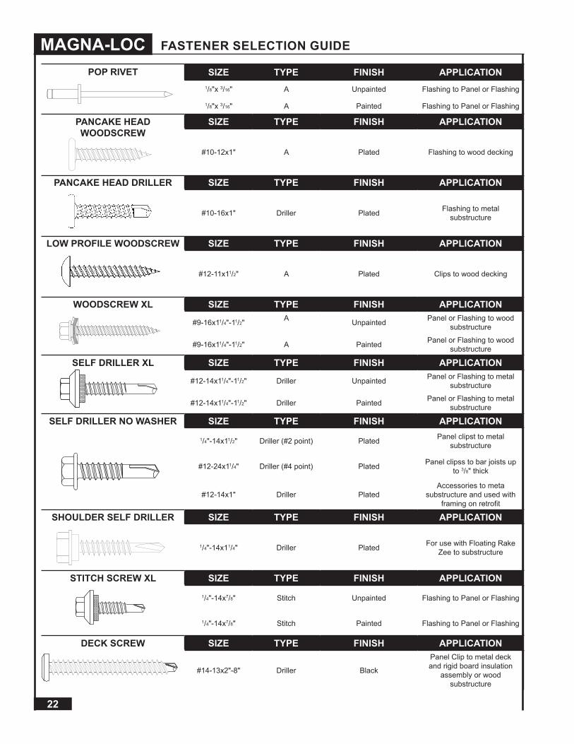
MAGNA-LOC FASTENER SELECTION GUIDE
POP RIVET SIZE TYPE FINISH APPLICATION1/8"x 3/16" A Unpainted Flashing to Panel or Flashing
1/8"x 3/16" A Painted Flashing to Panel or Flashing
PANCAKE HEAD WOODSCREW
SIZE TYPE FINISH APPLICATION
#10-12x1" A Plated Flashing to wood decking
PANCAKE HEAD DRILLER SIZE TYPE FINISH APPLICATION
#10-16x1" Driller Plated Flashing to metal substructure
LOW PROFILE WOODSCREW SIZE TYPE FINISH APPLICATION
#12-11x11/2" A Plated Clips to wood decking
WOODSCREW XL SIZE TYPE FINISH APPLICATION
#9-16x11/4"-11/2" A Unpainted Panel or Flashing to wood substructure
#9-16x11/4"-11/2" A Painted Panel or Flashing to wood substructure
SELF DRILLER XL SIZE TYPE FINISH APPLICATION
#12-14x11/4"-11/2" Driller Unpainted Panel or Flashing to metal substructure
#12-14x11/4"-11/2" Driller Painted Panel or Flashing to metal substructure
SELF DRILLER NO WASHER SIZE TYPE FINISH APPLICATION1/4"-14x11/2" Driller (#2 point) Plated Panel clipst to metal
substructure
#12-24x11/4" Driller (#4 point) Plated Panel clipss to bar joists up to 3/8" thick
#12-14x1" Driller PlatedAccessories to meta
substructure and used with framing on retrofit
SHOULDER SELF DRILLER SIZE TYPE FINISH APPLICATION
1/4"-14x11/4" Driller Plated For use with Floating Rake Zee to substructure
STITCH SCREW XL SIZE TYPE FINISH APPLICATION1/4"-14x7/8" Stitch Unpainted Flashing to Panel or Flashing
1/4"-14x7/8" Stitch Painted Flashing to Panel or Flashing
DECK SCREW SIZE TYPE FINISH APPLICATION
#14-13x2"-8" Driller Black
Panel Clip to metal deck and rigid board insulation
assembly or wood substructure

23
PHYSICAL PROPERTIES
FASTENER HEADDIA/TYPE
THREADDIA. O.D.
THREADDIA. I.D.
MINTENSILE
MIN.TORSIONAL
NOM.SHEAR
TRUSS HEAD WOODSCREW
#8-15x3/4"
Truss Hd.#2 Philips .162-.168 .105-.110 1672 lbs 61 In lbs 1087 lbs
PANCAKE HEAD WOODSCREW
#10-12x1"
.447 IN.#2 Philips .188-.194 .126-.133 1673 lbs 79 In lbs 1311 lbs
WOODSCREW
#9-16x1",11/2"
1/4" HWH .175-.181 .127-133 2429 lbs 80 In lbs 1355 lbs
LOW PROFILE WOODSCREW
12-11 x11/2"
#3 SquareDrive .201-.208 .125-.131 2050 lbs 81 In lbs 1369 lbs
PANCAKE HEAD DRILLER
#10-16x1" SELF DRILLING
#2 Philips .183-.189 .135-.141 1984 lbs 80 In lbs 1442 lbs
SELF DRILLER NO WASHER
1/4"-14x11/2" SELF DRILLING
3/8" HWH .240-.246 .185-.192
SELF DRILLER NO WASHER
#12-14x1",11/2" SELF DRILLING
5/16" HWH .209-.215 .157-.165
SELF DRILLER
#12-14x1",11/4",11/2" SELF DRILLING
5/16" HWH .209-.215 .157-.165
STITCH
1/4"-14x7/8" SELF DRILLING
5/16" HWH .240-.246 .185-.192
DECK SCREW
#14-13x2",4",5",6",8"
#3 Philips.448 Max .235-.242 .155
FASTENER TECHNICAL INFORMATION

24
MAGNA-LOC
FASTENERPlywood OSB Hard/Soft Wood
3/4" 5/8" 1/2" 19/32" 7/16" Spruce Fir Oak Pine
TRUSS HEAD WOODSCREW
#8-15x3/4"
461 340 377 98 375 405 593 464
PANCAKE HEAD WOODSCREW
#10-12x1"
615 521 339 290 257
WOODSCREW
#9-16x1",11/2"
565 498 326 223 1537
LOW PROFILE WOODSCREW
12-11 x11/2"
FASTENERSteel
3/8" 1/4" 3/16" 10 GA 12 GA(55)
14 GA(55)
16 GA(55)
18 GA(50)
22 GA(50)
PANCAKE HEAD DRILLER
#10-16x1" SELF DRILLING
1514 953 825 167
SELF DRILLER NO WASHER
1/4"-14x11/2" SELF DRILLING
2031 1172 1043 951 209
SELF DRILLER NO WASHER
#12-14x1",11/2" SELF DRILLING
1788 1056 850 790 180
SELF DRILLER
#12-14x1",11/4",11/2" SELF DRILLING
STITCH
1/4"-14x7/8" SELF DRILLING
DECK SCREW
#14-13x2",4",5",6",8"
PULL OUT VALUES - POUNDS
FASTENER TECHNICAL INFORMATION (CONT.)
25
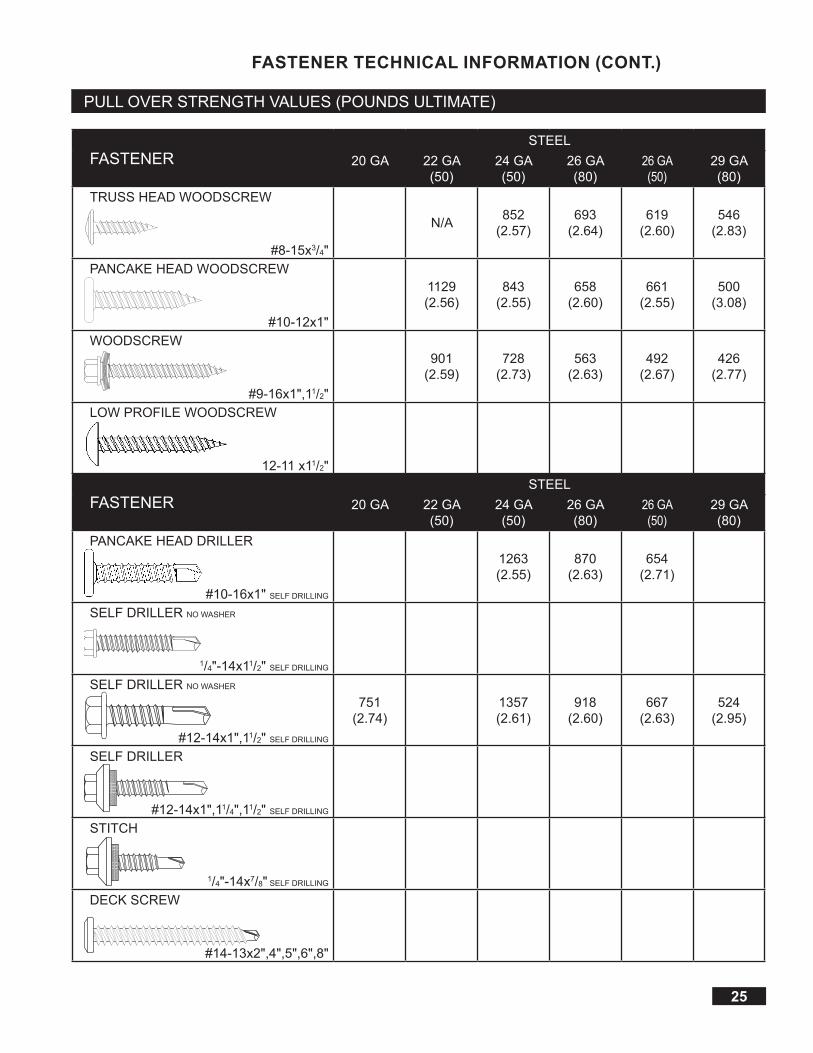
FASTENERSTEEL
20 GA 22 GA(50)
24 GA(50)
26 GA(80)
26 GA(50)
29 GA(80)
TRUSS HEAD WOODSCREW
#8-15x3/4"
N/A 852(2.57)
693(2.64)
619(2.60)
546(2.83)
PANCAKE HEAD WOODSCREW
#10-12x1"
1129(2.56)
843(2.55)
658(2.60)
661(2.55)
500(3.08)
WOODSCREW
#9-16x1",11/2"
901(2.59)
728(2.73)
563(2.63)
492(2.67)
426(2.77)
LOW PROFILE WOODSCREW
12-11 x11/2"
FASTENERSTEEL
20 GA 22 GA(50)
24 GA(50)
26 GA(80)
26 GA(50)
29 GA(80)
PANCAKE HEAD DRILLER
#10-16x1" SELF DRILLING
1263(2.55)
870(2.63)
654(2.71)
SELF DRILLER NO WASHER
1/4"-14x11/2" SELF DRILLING
SELF DRILLER NO WASHER
#12-14x1",11/2" SELF DRILLING
751(2.74)
1357(2.61)
918(2.60)
667(2.63)
524(2.95)
SELF DRILLER
#12-14x1",11/4",11/2" SELF DRILLING
STITCH
1/4"-14x7/8" SELF DRILLING
DECK SCREW
#14-13x2",4",5",6",8"
FASTENER TECHNICAL INFORMATION (CONT.)
PULL OVER STRENGTH VALUES (POUNDS ULTIMATE)

26
MAGNA-LOC
1. Metal Roof Deck Panels* No. 24 MSG min thick coated steel. Panel width, max 18 in., min 12 in.; rib height2 in. Panels continuous over two or more spans. The panel flat area may have optional striations or minorcorrugationsplaced at various locations in the panel flat area beginning min of 2 in. from side ribs. The upper flangeof the panel rib may be horizontal, or optionally formed down to form an angle of 0 degree to 90 degree betweenthe vertical segment and the top flange of the rib. End lap to occur adjacent to and within 12 in. of purlin (Item 6)with panels overlapped 2 in. min. An end lap back-up-plate (Item 2A) to be used. A bead of sealant may be used atpanel end laps and side ribs.Ribs to be seamed with an electric or hand seaming tool to form a flange with a tighthem. Seaming process to include the upper portion of the Panel Clips (Item 2).
BEST BUY METALS - “Magna-Loc 18”, “Magna-Loc 16”
2. Roof Deck Fasteners* (Panel Clips) Located at side of panels over purlins (Item 6). (Max spacing 60 in. OC).When wood thermal block (Item 4A) is used, clips to be located on top. Either of the following:
Fixed Clip (Not Shown) - One piece assembly fabricated from No. 22 MSG min thick steel, 3-1/2 in. wide. Floating Clip - Two piece assembly with a base fabricated from No. 16 MSG min thick steel, 2 in. wide and a top fabricated from No. 22 MSG min thick steel, 4-5/16 in. wide.
2A. End Lap Back-Up-Plate (Not shown) - No. 16 MSG min thick coated steel channel, 3 in. wide with two 3/8 in. deep legs. Max length 74 in. Located under the panel end lap (50 ksi min yield strength).
2B. Roof Deck Fasteners*(Cinch Plate) (Optional) - (Not Shown) - width 1-5/16 in., length 18 in. max. Fabricated from No. 20 MSG min thick stainless steel. Located over end lap.
2C. End Lap Back-Up-Plate (Optional) - (Not shown) - No. 16 MSG min thick coated steel. Width 11, 13 or 19 in., length 7 in. Two 3/4 in. by 3/4 in. tabs and a 1 in. deep vertical leg located at upslope edge of panel. Used with Item 2A when Item
*2B is not used (50 ksi min yield strength).
3. Fasteners (Screws) For panel clip-to-purlin attachment to be 1/4"-14 by min 1 in. long self drilling, self-tappinghex-washer-head plated steel screws. Two fasteners used per clip. Fasteners used at end lap to be one of thefollowing: No. 1/4-14 by 1 in. long Type AB point, self-drilling, self-tapping hex-washer-head plated or stainless steelscrews or No. 12-14 by 1-1/4 in. long self-drilling self-tapping hex-washer-head plated steel screws. Spacing for 16in. wide panels to be a 1, 3, 4, 4, 3 in. pattern; spacing for 18 in. wide panels to be a 1-1/2, 3-1/2, 4, 4, 3-1/2, 1-1/2in. pattern. When optional cinch plate (Item 2B) is used, four fasteners to be required, inserted into factory punchedguide holes.
4. Thermal Spacer (Optional) - Polyisocyanurate - 3/8 in. min, 2-3/8 in. max thick, 4 in. min width, length sized to fitbetween panel clips (Item 2).
5. Insulation (Optional) - Any compressible blanket insulation 8 in. max thick before compression, or 6 in. max thickwhen located between Thermal Spacer (Item 4) or Thermal Block (Item 4A) and purlin (Item 6).
6. Purlins No. 16 MSG min thick steel ( 50 ksi min yield strength ). Max spacing 60 in. OC.Refer to General Information, Roof Deck Constructions for items not evaluated.
*Bearing the UL Classification Mark
Construction No. 506October 16, 2001Uplift - Class 90Fire Not Investigated
UL 580 WIND UPLIFT INFORMATION
MAGNA-LOC
1
3
2
4A
5
6
60" MAX
3
124
65
4
21
5 6 3
Underwriters Laboratories Inc. ®LISTED

27
1. Metal Roof Deck Panels* No. 24 MSG min coated steel. Max panel width 18 in.; min 12 in. Rib height 2 in. Panelscontinuous over three or more clips (Item 2). The panel flat area may have optional striated or minor ribs placed atvarious locations in the panel flat area beginning min of 2 in. from side ribs. The upper flange of the panel rib maybe horizontal, or optionally formed down to produce an angle of 0 to 90° between the vertical segment and the topflange of the rib. Panel end lap 2 in. min. An end lap back-up plate (Item 2A) to be used at panel end lap. A beadof sealant may be used at panel end lap and side ribs. Ribs to be seamed with an electric or hand seaming tool toform a flange with a tight hem. Seaming process to include the upper portion of the panel clips (Item 2) .
BEST BUY METALS - “Magna-Loc 16”, “Magna-Loc 18”
2. Roof Deck Fasteners* - (Panel Clips) Located at side of panels (Item 1) over substructure (Item 3, 3A, 3B or 3C)and fastened through substructure to liner panel (Item 8) with max spacing of 48 in. OC or over sub-purlins (Item7) with max spacing of 48 in. OC; or when panel clips are fastened directly to plywood (Item 3B) as described inItem 6B, max spacing to be 36 in. OC.
Fixed Clip (Not Shown) - One piece assembly fabricated from No. 22 MSG min thick steel, 3-1/2 in. wide.
Floating Clip Two piece assembly with a base fabricated from No. 16 MSG min thick steel, 2 in. wide and a tab fabricated from No. 22 MSG min thick steel, 4-1/4 in. wide.
2A. End Lap Back-Up Plate (Not Shown) - No. 16 MSG min thick coated steel channel, 3 in. wide with two 3/8 in. deep legs. Max length 74 in. Located under the panel (Item 1) end lap (50 ksi min yeild strength).
2B. End Lap Back-Up-Plate (Optional) (Not Shown) - No. 16 MSG min thick coated steel. Width 11, 13 or 19 in., length 7 in. Two 3/4 in. by 3/4 in. tabs and a 1 in. deep vertical leg located at upslope edge of panel (50 ksi min yield strength).
2C. Roof Deck Fasteners*(Cinch Plate)-(Optional)-(Not Shown) width 1-15/16 in., length 18 in. max. Fabricated from No. 20 MSG min thick stainless steel. Located over end lap.
3. Substructure - (Gypsum Board) (Optional) - Min thick 1/2 in. To be placed on top of either the liner panel (Item8) or rigid insulation (Item 5). Combined thickness of the gypsum board and rigid insulation not to exceed 4 in. Alljoints to be taped with 2.5 in. wide joint tape.
3A. Substructure - (Plywood) (Optional) - (Not Shown) - Plywood decking, used in lieu of gypsum board (Item 3), to be nom 1/2 in. thick, exposure 1 sheathing, 40/20, CD. Located over rigid insulation (Item 5). Combined thickness of the plywood and rigid insulation not to exceed 4 in.
3B. Substructure - (OSB) (Optional) - (Not Shown) - OSB decking, used in lieu of gypsum board (Item 3), to be nom 1/2 in. thick. Located over rigid insulation (Item 5). Combined thickness of the OSB and rigid insulation not to exceed 4 in.
3C. Substructure - (Bearing Plate) (Optional) - Bearing plate to be used in lieu of gypsum board (Item 3) to be 4 by 4 in. by No. 18 MSG min thick coated steel (33 ksi min yield strength). Used under each clip (Item 2) over rigid insulation (Item 5) only when rigid insulation is located directly under panel (Item 1).
Construction No. 506AOctober 16, 2001Uplift - Class 90Fire Not Investigated
UL 580 WIND UPLIFT INFORMATION (CONT.)
MAGNA-LOC
See Item 2
See Item 2
6A
9
8
2 1
9
3 8 54
2 1
5 8
3
1
24
6A
6A5A

28
MAGNA-LOC
4. Vapor Barrier (Optional) - Single ply, used between the substructure (Items 3, 3A or 3B) and panel (Item 1).To be min 30 lb roofing felt.
5. Foamed Plastic - (Rigid Insulation) (Optional) Max thickness 3-1/2 in. when gypsum board (Item 3), plywood(Item 3A) or OSB (Item 3B) is used and 6 in. when bearing plates (Item 3C) are used. Min bearing strength tobe 20 psi. 1.8 pcf min density.
5A. Insulation (Optional) - Compressible blanket insulation 8 in. max thickness before compression. Used withsub-purlins (Item 7) only.
6. Fasteners - (Screws) Fasteners used to attach panel clips (Item 2) to sub-purlins (Item 7) to be No. 1/4-14 by1 in. long self-drilling, self-tapping, hex-washer-head, plated steel screws. Two fasteners per clip. Fastenersused at end lap of panel (Item 1) to be one of the following: No. 1/4-14 by 1 in. long, Type AB point self-drilling,self-tapping, hex-washer-head, plated or stainless steel screws or No. 12-14 by 1-14 in. long self-drilling, self-tapping, hex- washer-head, plated steel screws. Spacing for 12 in. wide panel to be 1, 3, 4, 4, 3, 1 in. pattern.Spacing for 16 in. wide panels to be 1, 3, 4, 4, 3, 1 in. pattern; spacing for 18 in. wide panels to be 1-1/2,3-1/2, 4, 4, 3-1/2, 1-1/2 in. pattern.
6A. Fasteners - (Screws) Fasteners used to attach panel clips (Item 2) through gypsum board, plywood, OSB, or bearing plate (Item 3, 3A, 3B, or 3C, respectively) and foamed plastic (Item 5) into liner panel (Item 8) to be No. 12-13, No. 3 Phillips drive, truss head, coated steel screws. Fastener length to penetrate liner panel min 1/2 in. Two fasteners per clip. Note: The panel clips may be fastened directly to the bearing plate using two No. 10-16 by 1 in. long self-drilling, self-tapping, pancake head No. 2 Phillips drive coated steel screws. The panel clip/bearing plate combination is to be fastened to the liner panel using two No. 12-13 truss head screws described above, inserted through guide holes in the bearing plates and into the liner panel. Min penetration 1/2 in.
6B. Fasteners - (Screws) (Not Shown) - Fasteners used to attach plywood Substructure (Item 3A) through rigid insulation (Item 5) to liner panel (Item 8) to be No. 14-13, No. 3 Phillips drive truss head screws. Fastener length to penetrate liner panel min 1/2 in. Total of 33 fasteners per 4 by 8 ft plywood sheet to be used. Fasteners located in five rows along the 4 ft length in a 3-9-12-12-9-3 in. pattern. The two outer rows are in a 3-9-12-12-12 12-12 12-9-3 in. pattern and the three center rows are in a 2-21-24-24-21-3 in. pattern. All spacing from board edges. Fasteners used to attach panel clips (Item 2) to plywood (when plywood is fastened to liner panel as indicatedabove) to be No. 10-12 by 1 in. long pancake head wood screw with No. 2 Phillips drive, or No. 10-12 by 1 in. long hex-head wood screw. Two fasteners per clip.
7. Sub-Purlin No. 16 MSG min thick coated steel (50 ksi min yield strength). Hat section, min 3/4 in. deep, 2 in.wide or Zee section, 2 in. wide, flanges 2 in. deep. Max spacing between sub-purlins to be 48 in. OC.Note: Screws used to attach sub-purlin to liner panel to be No. 12-13, No. 3 Phillips drive, truss head,coatedsteel. Max fastener spacing to be 12 in. OC for Zee section with fasteners located in center of lowerflange. For hat section, two screws, spaced 24 in. OC, located at each side of channel to be used.
8. Liner Panel - (Steel Deck) No. 22 MSG min thick coated steel. Fabricated to various profiles (33 ksi minyieldstrength). Steel deck depth and profile, support spacing (max 6 ft), method of positioning (end and sidelaps), and fastening of deck to supports to be per deck manufacturer’s and local code requirements for upliftloading.
9. Liner Panel Supports - Purlins No. 16 MSG min thick steel (50 ksi min yield strength). Spacing to depend ondesign considerations for uplift loading: max 6 ft, 0 in. OC.
Joists (Optional) - (Not Shown) - Open web steel joist having a min No. 16 MSG upper flange (50 ksi min yield strength) or a min 1/8 in. thick upper flange (33 ksi min yield strength). Max spacing 6 ft, 0 in. OC. Refer to general information, Roof Deck Construction, (Roofing Materials and System Directory) for items not evaluated.
*Bearing the UL Classification Mark
Construction No. 506A (cont.)October 16, 2001Uplift - Class 90Fire Not Investigated
MAGNA-LOC
UL 580 WIND UPLIFT INFORMATION (CONT.)
Underwriters Laboratories Inc. ®LISTED

29
1. Metal Roof Deck Panels* No. 24 MSG min coated steel. Max panel width 18 in.; min 12 in. Rib height 2 in.Panels continuous over three or more clips (Item 2). The panel flat area may have optional striated or minorribs placed at various locations in the panel flat area beginning min of 2 in. from side ribs. The upper flangeof the panel rib may be horizontal, or optionally formed down to produce an angle of 0 to 90° between thevertical segment and the top flange of the rib. Panel end lap 2 in. min. An end lap back-up plate (Item 2A) tobe used at panel end lap. A bead of sealant may be used at panel end lap and side ribs. Ribs to be seamedwith an electric or hand seaming tool to form a flange with a tight hem. Seaming process to include the upperportion of the panel clips (Item 2) .
BEST BUY METALS - “Magna-Loc 16”, “Magna-Loc 18”
2. Roof Deck Fasteners - (Panel Clips) Located at side of panels (Item 1) over substructure (Item 3, 3A, 3B or3C with max spacing of 36 in. OC), or plywood decking (Item 7 with max spacing of 36 in. OC). Either of thefollowing:
Fixed Clip (Not Shown) - One piece assembly fabricated from No. 22 MSG min thick steel, 3-1/2 in. wide. Floating Clip Two piece assembly with a base fabricated from No. 16 MSG min thick steel, 2 in. wide and a tab fabricated from No. 22 MSG min thick steel, 4-1/4 in. wide.
2A. End Lap Back-Up Plate (Not Shown) - No. 16 MSG min thick coated steel channel, 3 in. wide with two 3/8 in. deep legs. Max length 74 in. Located under the panel (Item 1) end lap (50 ksi min yield strength).
2B. End Lap Back-Up-Plate (Optional) (Not Shown) - No. 16 MSG min thick coated steel. Width 11, 13 or 19 in., length 7 in. Two 3/4 in. by 3/4 in. tabs and a 1 in. deep vertical leg located at upslope edge of panel (50 ksi min yield strength).
2C. Roof Deck Fasteners*(Cinch Plate)-(Optional)-(Not Shown) width 1-5/16 in. length 18 in. max. Fabricated from No. 20 MSG min thick stanless steel. Located over end lap.
3. Substructure - (Gypsum Board) (Optional) - Min thick 1/2 in. To be placed on top of either the plywooddecking (Item 7) or rigid insulation (Item 5). Combined thickness of the gypsum board and rigid insulation notto exceed 4 in. All joints to be taped with 2.5 in. wide joint tape.
3A. Substructure - (Plywood) (Optional) - (Not Shown) - Plywood decking, used in lieu of gypsum board (Item 3), to be no 1/2 in. thick, exposure 1 sheathing, 40/20, CD. Located over rigid insulation (Item 5). Combined thickness of the plywood and rigid insulation (Item 5) not to exceed 4 in.
3B. Substructure - (OSB) (Optional) - (Not Shown) - OSB decking, used in lieu of gypsum board (Item 3), to be nom 1/2 in. thick. Located over rigid insulation (Item 5). Combined thickness of the OSB and rigid insulation not to exceed 4 in.
3C. Substructure - (Bearing Plate) (Optional) - (Not Shown) - Bearing plate to be used in lieu of gypsum board (Item 3) to be 4 by 4 in. by No. 18 MSG min thick coated steel (33 ksi min yield strength). Used under each clip (Item 2) over rigid insulation (Item 5) only when rigid insulation is located directly under panel (Item 1).
4. Vapor Barrier (Optional) - Single ply, used between the substructure (Items 3, 3A or 3B) or plywood decking(Item 7) and panels (Item 1). To be min 30 lb roofing felt.
Construction No. 506BOctober 16, 2001Uplift - Class 90Fire Not Investigated
UL 580 WIND UPLIFT INFORMATION (CONT.)
MAGNA-LOC
36" Max
67
42 1
4
2
1
7
6
8

30
MAGNA-LOC
5. Foamed Plastic - (Rigid Insulation) - (Optional) Max thickness 3-1/2 in. when gypsum board (Item 3),plywood (Item 3A) or OSB (Item 3B) is used and 6 in. when bearing plates (Item 3C) are used. Min bearingstrength to be 20 psi. 1.8 pcf min density.
6. Fasteners - (Screws) Fasteners used to attach panel clips (Item 2) to plywood substructure (Item 3A) orplywood decking (Item 7) to be No. 10-12 pancake head, No. 2 Phillips drive, A-point, coated steel screw.Fastener length to penetrate plywood min 1/2 in. Two fasteners per clip.
6A. Fasteners - (Screws) Fasteners used to attach panel clips (Item 2) through gypsum board, OSB or bearing plate (Item 3, 3B, or 3C, respectively) and foam plastic insulation (Item 5) into plywood deck (Item 7) to be No. 10-12 pancake head, No. 2 Phillips drive, A-point, steel screw. Two screws used per clip.
Note: The panel clips may be fastened to the bearing plate using two No. 10-16 by 1 in. long self-driving,self-tapping, pancake head No. 2 Phillips drive coated steel screws. The panel clip/bearing plate combination is to be fastened to the plywood deck using two No. 12-13 No. 3 Phillips Drive coated steel truss head screws, inserted through a guide hole in the clip and bearing plate and into the plywood deck.
6B. Fasteners - (Screws) (Not Shown) - Fasteners used to attach plywood Substructure (Item 3A) through rigid insulation (Item 5) into plywood deck (Item 7) to be No. 14-13, No. 3 Phillips drive truss head screws. Fastener length to penetrate plywood deck min 1/2 in. Total of 33 fasteners per 4 by 8 ft plywood sheet to be used. Fasteners located in five rows along the 4 ft length in a 3-9-12-12-9-3 in. pattern. The two outer rows are in a 3-9-12-12-12-12-12-12-9-3 in. pattern and the three center rows are in a 3-21-24-24-21-3 in. pattern. All spacingfrom board edges.
6C. Fasteners - (Screws) (Not Shown) - Fasteners used at end laps of panel (Item 1) to be one of the following: No. 1/4-14 by 1 in. long, Type AB point self-drilling, self-tapping, hex-washer-head, plated or stainless steel screws or No. 12-14 by 1-1/2 in. long self-drilling, self-tapping, hex-washer-head, plated steel screws. Spacing for 16 in. wide panels to be 1, 3, 4, 4, 3 in. pattern; spacing for 18 in. wide panels to be 1-1/2, 3-1/2, 4, 4, 3-1/2, 1-1/2 in. pattern.
7. Plywood Deck Plywood decking to be graded per PS83 specifications, 19/32 in. thick, exposure 1, APA ratedsheathing, 40/20 in. OC, square edged. Butt ends not blocked.
8. Purlins - Deck Supports Spaced a max of 24 in. OC. Any of the following types may be used:A. No. 22 MSG min thick coated steel. (33 ksi min yield strength.)B. Graded dimension lumber, No. 2 or better.
8A. Plywood Fasteners (Not Shown) - Fasteners used to attach the plywood deck (Item 7) to the supports (Item 8) to be as follows:
a. For plywood-to-wood supports, No. 8-18 by 1-7/8 in. long bugle-head steel screws with a No. 2 Phillipsdrive, a “Hi-Low” thread pattern and an “S-Point”.
b. As an alternate to Item a, No. 8d common deformed shank nails may be used.c. For plywood-to-steel supports for a steel thickness less than No. 20 MSG, No. 7-19 by 1-1/4 in. long
bugle-head steel screws with a No. 2 Phillips head drive, a “Hi-Low” thread pattern and an “S-Point”. Fora steel thickness greater than No. 20 MSG to No. 16 MSG, No. 6-20 by 1-1/4 in. long in. long bugle-headsteel screws with a No. 2 Phillips drive and an S12 (Tek/3) point.
Spacing - For all fastener types to be 6 in. OC at the plywood edges and 12 in. OC in the interior.Refer to general information, Roof Deck Construction, (Roofing Materials and System Directory) for items not evaluated.
*Bearing the UL Classification Mark
Construction No. 506B (cont.)October 16, 2001Uplift - Class 90Fire Not Investigated
UL 580 WIND UPLIFT INFORMATION (CONT.)
MAGNA-LOC
Metal Roof Deck Panels
We have fire resistance ratings for various products conducted according to test criteria set forth by 'Underwriters Laboratories' "Standard Fire Tests of Building Construction and Material" (ANSI/UL 263). This test procedure is identical to ASTM E-119 and NFPA 251.
The fire resistance rating is for the total assembly and not just the external metal panel. Ratings are expressed in hours and vary depending upon the assemblies.
In general, the test criteria is to evaluate the assembly's ability to continue to support the superimposed loads and resist the passage of flame, high temperatures, or hot gases which will ignite combustible materials. The test assemblies are identified by an alpha-numeric design number.
For detail information on specific assemblies and hourly ratings see UL Fire Resistance Directory.
UL 263 Fire Resistance RatingsMAGNA-LOC
Underwriters Laboratories Inc. ®LISTED

31
SECTION PROPERTIES AND LOAD TABLES
MAGNA-LOC SECTION PROPERTIES
GAUGE WIDTHin
YIELDksi
WEIGHTpsf
TOP IN COMPRESSION BOTTOM IN COMPRESSIONIxx
in4/ftSxxin3/ft
Ma(k-in)/ft
Ixxin4/ft
Sxxin3/ft
Ma(k-in)/ft
24 16 50 1.25 0.1785 0.1013 3.04 0.0855 0.0754 2.2622 16 50 1.64 0.2475 0.1424 4.27 0.1178 0.1070 3.2124 18 50 1.21 0.1620 0.0900 2.70 0.0760 0.0669 2.0122 18 50 1.58 0.2240 0.1261 3.78 0.1047 0.0951 2.85
1. Theorectical section properties have been calculated per AISI 2012 "North American Specification for the Design of Cold-Formed SteelStructural Members." Ixx and Sxx are effective section properties for deflection and bending.
2. Allowable load is calculated in accordance with AISI 2012 specifications considering bending, shear, compined bending and shear,deflection, and ASTM 1592 testing on 16 ga purlins. Allowable load considers the worst case of 3 and 4 equal span conditions.Allowable load does not address web crippling or fasteners/support connection and panel weight is not considered.
3. Deflection consideration is limited by a maximum deflection ratio of L/180 of span.4. Allowable loads do not include a 1/3 stress increase in uplift.
ALLOWABLE UNIFORM LIVE LOADS PSF3 or more Equal Spans
GAUGE WIDTHin
YIELDksi
WEIGHTpsf
Inward Load Outward Load2' 2.5' 3' 3.5' 4' 5' 2' 2.5' 3' 3.5' 4' 5'
24 16 50 1.25 368 249 179 135 105 68 123 111 99 87 75 51
22 16 50 1.64 549 367 261 195 151 98 128 119 110 100 91 73
24 18 50 1.21 327 221 159 119 93 60 111 99 87 75 63 39
22 18 50 1.58 488 326 232 173 134 87 120 108 95 83 71 46
MAGNA-LOC180 SECTION PROPERTIES
GAUGE WIDTHin
YIELDksi
WEIGHTpsf
TOP IN COMPRESSION BOTTOM IN COMPRESSIONIxx
in4/ftSxxin3/ft
Ma(k-in)/ft
Ixxin4/ft
Sxxin3/ft
Ma(k-in)/ft
24 16 50 1.24 0.1418 0.0779 2.37 0.0720 0.0656 1.9722 16 50 1.63 0.2025 0.1134 3.40 0.1005 0.0885 2.6624 18 50 1.21 0.1287 0.0695 2.09 0.0640 0.0582 1.7522 18 50 1.58 0.1840 0.1013 3.04 0.0893 0.0787 2.36
ALLOWABLE UNIFORM LIVE LOADS PSF3 or more Equal Spans
GAUGE WIDTHin
YIELDksi
WEIGHTpsf
Inward Load Outward Load2.5' 3' 3.5' 4' 4.5' 5' 2.5' 3' 3.5' 4' 4.5' 5'
24 16 50 1.35 352 232 164 121 94 60 95 85 75 65 55 35
22 16 50 1.74 490 320 224 166 127 82 140 127 114 101 88 63
24 18 50 1.31 313 206 145 108 83 54 100 90 80 70 59 39
22 18 50 1.69 436 284 199 147 113 73 126 114 103 91 79 56

32
MAGNA-LOC
CAUTIONImproper loading and unloading of bundles and crates may result in bodily harm and/or material damage. We are not responsible for bodily injuries and/or material damages
resulting from improper loading and unloading.
It is the responsibility of the installer to unload material from the delivery truck. The installer shall be responsible for providing suitable equipment for unloading of material from the truck.
After receiving material, check the condition of the material, and review the shipment against the shipping list to ensure all materials are accounted for. If damages or shortages are discovered, it should be noted on the Bill of Lading at the time of delivery. A claim should be made against the carrier as soon as possible. We are not responsible for any damages or shortages unless they are documented in writing and presented to Best Buy Metals within 48 hours.
Each bundle should be handled carefully to avoid being damaged. Care should be taken to prevent bending of the panel or abrasion to finish. Whenever possible, the bundle should remain crated until it is located in its place of storage. If bundles must be opened, we recommend you recrate them before lifting. To avoid damage please lift the bundle at its center of gravity.
Forklift - A forklift may be used for panels up to 20'-0" long. Please make sure the forks are at their maximum separation. Do not transport open bundles. When transporting bundles across rough terrain, or over a longer distance, some means of supporting the panel load must be used.
Crane - A crane should be used when lifting panels with lengths greater than 20'-0". Please be sure to utilize a spreader bar to ensure the even distribution of the weight to the pick up points. As a rule when lifting panels, no more than 1/3 of the length of the panel should be left unsupported. Never use wire rope because this will damage the panels.
HANDLING MATERIAL
RECEIVING MATERIAL
GENERAL HANDLING
MECHANICAL HANDLING

33
When handling painted steel care should be taken to prevent scratching of material. Clean gloves should be worn at all times to prevent a reaction with salts found on bare skin. Installers should wear rubber sole shoes to keep from scuffing material while walking on the roof.
Handling of individual panels should be done carefully and properly to avoid bending or damaging. Magna-Loc panels should be carried by grasping the edge of the panel so that the Magna-Loc panel is vertical to the ground. The Magna-Loc panel should not be carried with the panel horizontal to the ground as this could cause the panel to buckle or bend in the center.
Normally individual panels can be handled by people placed every 6'-0" to 8'-0" along the length of the panel.
MANUAL HANDLING
CORRECT
6' - 8' MAX
HANDLING MATERIAL (cont.)
INCORRECT

34
MAGNA-LOC
Magna-Loc Panels
Tarpaulin
Please inspect panels for moisture accumulation. If moisture has formed, the panels should be unbundled, wiped dry, and allowed to dry completely. Once dry, carefully restack the panels and loosely recover allowing for ample air circulation.
Bundled sheets should be stored high enough off of the ground to allow for air circulation and prevent contact with accumu-lating water. If possible, elevate one end of the bundle to allow any moisture to run off the panels. We recommend covering the bundle with a tarpaulin. Do not use tight fitting plastic-type tarpaulins as panel bundle covers. While they may provide protection from heavy downpours, they can also retard necessary ventilation and trap heat and moisture that may accelerate metal corrosion. If panels are to be stored in possible bad weather, we suggest they be stored inside. Extended storage of panels in a bundle is not recommended. Under no circumstances should the sheets be stored near or come in contact with salt water, corrosive chemicals, ash, or fumes generated or released inside the building or nearby plants, foundries, plating works, kilns, fertilizer and wet, green treated lumber.
STORAGE
GENERAL
Tarpaulin
Elevate end of bundle
Slope bundle

35
To facilitate the handling of Magna-Loc panels, panel bundles can be lifted and placed on the roof. Bundles need to be placed on the roof in order for the roof structure to handle the weight. Loading capabilities of the structure must be checked.
When lifting packaged sheets, make certain they are adequately supported. Panels less than 20'-0" in length can normally be lifted with a forklift; however, when lifting panels in excess of 20'-0", it is recommended that a spreader bar and slings be used. As a rule, when lifting, no more than 1/3 of the length of the panel should be left unsupported.
Make a plan for bundle placement by determining how much area a bundle of panels will cover. Bundles should be placed on the roof in accordance with the direction the panel will be installed. Consider where the string line, if any, is to run at the eave to set roof panels by. Roof bundles should not interfere with this string line.
STORAGE (cont.)
STORAGE ON ROOF
Spacer Bar
Magna-Loc Panels
Open FramingWood Blocking
Rigid Frame

36
MAGNA-LOCCare of metal panels and flashings must be exercised throughout erection. Foot traffic can cause distortion of panel and damage to finish. Traffic over the installed system must be kept to an absolute minimum. If continuous foot traffic is neces-sary for maintenance over certain areas of the roof, then a permanent walkway should be installed.
If metal panels are installed over open framing, do not use the roof panel as a walking platform. The roof panels will not withstand the weight of a person standing at the edge of the panel. Provide walking platforms to avoid any panel damage as shown below.
When walking on the roof panels is unavoidable, walk only in the flats of the panel. Walking on the ribs can cause damage to the panels. If Magna-Loc is installed over open framing, step in the flat of the panel only and as close to the framing as pos-sible.
FOOT TRAFFIC
Magna-Loc Panels
Foot Traffic
Framing
OVER OPEN FRAMING
Walking Platforms

37
Framing
Tin snips or a "nibbler" type electric tool are recommended for field cutting Magna-Loc panels. Cutting the steel generates slivers or metal chips. These slivers and metal chips must be immediately removed from the Magna-Loc panels because they will damage the finish and shorten the life of the product.
One method of preventing this problem is to flip the Magna-Loc panels over when cutting. This allows the slivers and metal chips to be brushed from the back side and avoids damaging the paint on the top side of the panels.
When cutting Magna-Loc panels, goggles must be worn for eye protection.
CAUTIONAll product surfaces should be free of debris at all times. Installed surfaces should be
wiped clean at the end of each work period. Never cut panels over metal surfaces. Metal shavings will rust on the surface, voiding the warranty.
All painted panels and flashings have a factory applied baked on finish. Handling and installing panels may result in some small scratches or nicks to the paint finish. Touch-up paint is available in matching colors. It is recom-mended that a small brush be used to apply touch-up paint to those areas that are in need of repair. Touch-up paint does not have the superior chalk and fade resistance of the factory applied paint finish and will normally discolor at an accelerated rate. Aerosol paint should not be used because of the overspray that may occur.
FIELD CUTTING AND TOUCH-UP
TOUCH-UP PAINT
FIELD CUTTING
TOUCH-UP PAINT
SPRAY PAINT

38
MAGNA-LOC
To prevent wobbling - Make sure fastener head is completely engaged in the socket. If the head does not go all the way in the socket - tap the magnet deeper into the socket to allow full head engagement. Metal chips will build up from drilling and should be removed from time to time.Protect drill point - Push only hard enough on the screw gun to engage clutch. This prevents excess friction and burn out of the drill point. Correct pressure will allow screw to drill and tap without binding.Drilling through sheet and insulation - Ease up on pressure when drilling through insulation to avoid striking the purlin or girt with the point - apply more pressure after drill point contacts purlin or girt.Drilling through purlin overlaps - Drilling through lapped purlins requires extra care. Excessive voids between purlins sometimes damages drill points and two self-drillers might be necessary to complete the operation. It is sometimes advanta-geous to predrill.
Recommended Tool Type - Use depth locating nose or adjustable clutch on screw gun to prevent overdrilling and strip out. Do not use impact tools or runners.Seating the washer - Apply sufficient torque to seat the washer - do not overdrive the fastener.
TOO LOOSESealing material is not visible;not enough compression to
seal properly.
CORRECTSealing material slightly vis-ible at edge of metal washer.
Assembly is watertight.
TOO TIGHTMetal washer deformed; sealing material pressed
beyond washer edge.
WO
OD
SCR
EWSE
LF D
RIL
LER
FASTENER INSTALLATION TECHNIQUE
Whether over solid substrate or open structural framing, panel distortion may occur if not applied over properly aligned and uniform substructure.
The installer should check the roof deck for squareness before installing Magna-Loc panels. Several methods can be used to verify squareness of the structure for proper installation of the panels.
METHOD "A" - One method for checking the roof for squareness is to measure diagonally across one slope of the roof from similar points at the ridge and eave and obtain the same dimension.
METHOD "B" - The 3-4-5 triangle system may also be used. To use this system measure a point from the corner along the edge of the roof at a module of three (3). Measure a point from the same corner along another edge at a module of four (4). Then by measuring diagonally between the two points established, the dimension should be exactly a module of five (5) to have a square corner. Multiple uses of this system may be required to determine building squareness. If the endwall cannot be made square, the roof system cannot be installed as shown in these instructions.
CONDITION OF SUBSTRUCTURE
Method A
Method B4
30
3035
DESIGN / INSTALLATION CONSIDERATIONS

39
Proper design and installation of vapor barriers and ventilation systems are important to prevent condensation and the result-ing problems of moisture damage and loss of insulation efficiency.
Condensation occurs when moisture laden air comes in contact with a surface temperature equal to or below the dew point of the air. This phenomenon creates problems that are not unique with metal buildings; these problems are common to all types of construction.
The underside of the metal roof on a typical metal building (no attic) should be protected from condensation by insulating with a faced insulation. This should reduce the potential of condensation forming on the underside of the panels.
On buildings that have an attic space or are being retrofitted with a metal roofing system, vents should be placed at both the eave and peak of the roof in order to prevent a buildup of moisture (humidity) in the attic space.
VENTILATION
TYPICAL METAL BUILDING (NO ATTIC)
Vent
Vent at wall Vent at eave
BUILDING WITH ATTIC OR RETROFITTED
Vent
Insulation
In most cases insulation is installed directly under roof panels. Insulation is recommended on all applications to act as a sound barrier, prevent condensation, and increase insulating value of a roof system.
Many different types of insulation can be used with the metal roof panels. Blanket, batt, rigid, and reflective insulation are just to name a few. Please contact your insulation supplier for specific recommendations on installation of insulation and vapor barriers.
When applying a compressible type of insulation over open framing members. Rigid thermal blocks can be used to help eliminate heat lost at purlin locations.
INSULATION
Compressible Insulation
Area of least resistance to heat loss
Purlin
Thermal Block
Magna-Loc Panel
Resistance to heat loss is increased
CAUTIONUse extreme care when working next to insulation. The insulation will provide a false sense of
security by hiding the view of the ground below
DESIGN / INSTALLATION CONSIDERATIONS (cont.)

40
MAGNA-LOC DESIGN / INSTALLATION CONSIDERATIONS (cont.)
Steel roofing panels are subject to dimensional changes after installation due to exposure to varying temperatures. The great-est influence is solar energy. Steel roofing absorbs various amounts of heat depending upon color, finish, angle of exposure, and time of exposure. The relationship of the roof temperature to building structural temperature must be considered when designing a Magna-Loc roof system. The floating clips for the Magna-Loc panels are designed for expansion and contraction of the panels in the longitudinal direction. Lateral expansion and contraction is accommodated by the configuration of the panel cross section and causes negligible panel movement. When the total length of panel run exceeds the capability of the clips to accommodate the thermal movement, expansion joints must be designed into the structure.
SYSTEM EXPANSION / CONTRACTION
The Magna-Loc roof system can be installed with components that allow the panels to either float independently or fix per-manently to the substructure. Choice of system will depend upon building design and regional temperature range (from summer highs to winter lows).
SELECTION OF SYSTEM COMPONENTS
Magna-Loc Floating Clips- The floating clips allow the roof surface (panels) to move independently of the roof substructure to allow for thermal expansion and contraction. These clips are designed with a vertical tab that slides along the base section of the clip.Magna-Loc Fixed Clips- Fixed clips may be used on panel runs of less than 20'-0", unless thermal expansion and contraction is a consideration. When utilizing a Fixed Utility Clip, a Pancake Head fastner must be used.
MAGNA-LOC FIXED CLIPMAGNA-LOC FLOATING CLIP
Vertical TabBase
The following chart should be used to determine proper fasteners required for clip installation on the selected applica-tions. (See Fastener Selection Guide page 17 for other fasteners available.)
* Length of Dekfast will vary depending on the total thickness of the rigid insulation and metal. (See page 22.) ** Contact your representative for more information. (See pages 2 and 3.)
2 FASTENERS
2 FASTENERS
2 FASTENERS
CLIP OVER RIGID INSULATION / METAL DECK
2 FASTENERS
2 FASTENERS
1/4-14 x 11/2" SELF DRILLER NW
1/4-14 x 11/2" SELF DRILLER NW
#12-11x11/2" LOW PROFILE WOODSCREW 2 FASTENERS
NUMBER REQUIREDTYPE OF FASTENERAPPLICATION INSTALLATION
REQUIREMENTS
24 GAUGE
24 GAUGE
**CLIPSPACING
5'-0" O.C.
4'-0" O.C.
5'-0" O.C.
STANDARD
#12-11x11/2" LOW PROFILE WOODSCREW22 GAUGE 4'-0" O.C.
CLIPS OVER PURLINS
(16 GA. MIN)
CLIPS OVER 5/8" WOOD DECK
DECK SCREW #14*24 GAUGE 4'-0" O.C.
22 GAUGE 4'-0" O.C. DECK SCREW #14*
STANDARD
STANDARD
STANDARD
STANDARD
STANDARD
22 GAUGE
RAKE ZEE
21/8" UTILITY
23/8" LOW
33/8" HIGH
SYSTEM COMPONENTSSYSTEM CLIP EAVE PLATE THERMAL BLOCK INSULATION
UTILITY
LOW
HIGH
21/8" UTILITY(FIXED ONLY)
23/8" LOW(FLOATING OR FIXED)
33/8" HIGH(FLOATING)
3/8" LOW
13/8" HIGH
NONE REQUIRED
NONE REQUIRED
1"
1/2" TO 4" BLANKET
4" TO 6" BLANKET
4" TO 6" BLANKET
NONE REQUIRED

41
Factory Notched Panels - We can provide factory notched panel ends to eliminate material-build up or reliance on field notching for weathertight seams at panel endlaps.
Factory Prepunched Panels - We can provide panels that have been factory punched with holes for proper placement of fasteners at panel endlaps.
STANDARD PANEL: Used when endlapping of panels is not required One panel from eave to peak of roof No notching No punching
PEAK PANEL: Used when endlapping of panels is required Used as upper panel of endlapping run Pre punched holes for endlap fastener placement No notching
*Panel is notched and punched both ends or neither
MID PANEL: Used on runs where more than (2) panels are needed from eave to
peak Not required if only (2) panels are used from eave to peak Notched for panel endlapping Prepunched holes for endlap fastener placement
EAVE PANEL: Used when endlapping of panels is required Used as lower panel of endlapping run Notched for panel endlapping No punching*Panel is notched and punched both ends or neither**Notch trailing end only
One panel - Eave to Peak
Two or more panels - Eave to PeakStandard Panel
Eave Eave
Peak Peak Peak Panel
Mid Panel
Eave Panel
*Denver, CO**Sellersburg, IN
*Denver, CO**Sellersburg, IN
*Denver, CO**Sellersburg, IN
*Denver, CO**Sellersburg, IN
DESIGN / INSTALLATION CONSIDERATIONS (cont.)

42
MAGNA-LOC INSTALLATION PROCEDURE OVERVIEWThe following procedures (pages 22-47) are presented as a general guide for installing Magna-Loc panels, flashings, and accessories on a typical building or residence. Details are shown for installing Magna-Loc and related flashings over solid decking and over open framing. For other applications please contact your representative.
The installation procedures will involve:• Installation of Floating Rake Zee. (page 22)• Installaton of Eave plate.• Installing panel from left to right (Looking from Eave to Peak.)• Panel Clip installation.• Endlapping of panel.• Sidelapping of panel.• Termination of panel.• Seaming panels.• Eave condition installation.• Gutter condition installation.• Valley condition installation.• Endlap condition installation.• Rake condition installation.• Rakewall condition installation.• Expansion Joint condition installation.• Endwall condition installation.• High Side Eave condition installation.• Ridge / Hip condition installation.
Ridge (See Pages 66-68)
Magna-Loc Panel (See Pages 8-10)
End Dam (See Page 78)
Floating Rake Zee (See Page 43)
SSR Rake Cleat (See Pages 59 & 61)
Rake (Off Module) (See Pages 60)
Gutter Support(See Page 55)
Gutter (See Page 55)
Eave Plate (See Page 44)

43
INSTALLATION OF PANEL
Note: The Floating Rake Zee must be attached to the framing member along the rake. Size of Floating Rake Zee can vary, (see System Components list on page 20). The following procedures are based on systems utilizing floating panel clips. For systems utilizing fixed panel clips, the Floating Rake Zee is not required to move along its slotted base, (see step 2).
12"
Butt ends
Shoulder Self Driller in center of slot
Floating Rake Zee
Rake AngleRoof Purlin / Eave Strut
6" to 12"
Floating Rake Zee
Purlin
Building Peak
INSTALLING PANEL CLIP
STEP1
INSTALLING FLOATING RAKE ZEE
Steps:1. At the eave of the building (looking eave to peak), align the Floating Rake Zee flush with the existing rake angle/framing.
It is critical that the Floating Rake Zee be straight and square with the building as it controls the alignment of theroof panels.
2. Fasten Floating Rake Zee with ¼"-14 x 1¼" Shoulder Self Driller screws into the center of each slot, (12" intervals).Do not overtighten screws. Movement of the Floating Rake Zees are imperative for proper installation of theroof system.
3. If two or more Floating Rake Zees are required, butt ends of Floating Rake Zees (Do not overlap) and continue fastening.4. If necessary, field cut Floating Rake Zee to terminate 6"-12" from peak of building.5. Install Floating Rake Zee on the opposite end where the panels terminate using the same procedures as above.
6. After applying Floating Rake Zees, insulation (if required) can be installed. Roll out insulation eave to peak, laying sideof insulation on Floating Rake Zees.
7. Avoid side lap of insulation from occurring directly beneath side lap of panel.

44
MAGNA-LOC
INSTALLING PANEL CLIP
STEP2
Note: The Eave Plate serves as an extension of the structure to support and fasten (if required) the panel at the eave on applications utilizing the Low or High Floating Clip Systems. Size of Eave Plate can vary (see System Components list on page 20).
Align Eave Plate With Finished Wall Surface
Floating Rake Zee
12"
Eave Plate
Butt ends
Self Driller no Washer
INSTALLATION OF PANEL (cont.)
INSTALLING EAVE PLATE
Steps:1. If using blanket insulation, the Eave Plate may be used to secure the insulation at the eave. Be sure to remove the
fiberglass and fasten only the vapor barrier to avoid wicking.2. Place pre-punched leg of Eave Plate on top of eave framing member. Align the top leg of the Eave Plate flush with
the finished wall surface at the eave of the building.
3. Fasten Eave Plate to eave framing member with #12 -14 x 1" or #12 -14 x 11/4" Self Driller No Washer screws 12"o.c. Donot fasten through Eave Plate into Floating Rake Zee. Movement of the Floating Rake Zee is imperative for properinstallation of roof system.
4. If two or more Eave Plates are required, butt ends of the Eave Plates (Do Not Overlap) and continue fastening.

45
INSTALLATION OF PANEL (cont.)
INSTALLING FIRST PANEL
Female Leg Male Leg
Floating Rake Zee
2"
Gutter Drip
First Magna-Loc Eave Panel
Self Driller XL
Note: Eave, Gutter Drip, Gutter, Valley or any low side flashing must be installed prior to installation of roof panel. The following steps are for installing Magna-Loc from left to right. Magna-Loc may be installed from right to left if end lapping of panels is not required (See page 60 for Off Module panel installation).
16" PROFILE FASTENING PATTERN(Additional fasteners may be required at valley condition)
18" PROFILE FASTENING PATTERN(Additional fasteners may be required at valley condition)
115/32" 31/4" 31/4" 31/4" 31/4"
31/4" 31/4" 31/4" 31/4"
115/32"
215/32" 215/32"
1 235 4
1 235 4
#12-14 x 11/4" Self Driller XL (See above)
"C" Clamp
2" Overhang
Gutter Drip
Peel back Double Bead Tape Sealant Paper
STEP3
Steps:1. Place a row of Double Bead Tape Sealant across top of Gutter Drip flashing. Be sure to place sealant where fastener will
be placed.2. Position the first panel so the female leg is on top of the Gutter Drip and the panel is against the vertical leg of the
Floating Rake Zee.3. Slide the panel over the eave flashing, 2" past the finished wall surface.4. Use a C-clamp to hold the panel against the vertical leg of the Floating Rake Zee. Lift panel at the Eave Plate and strip off
the paper backing on the Double Bead Tape Sealant.
5. Recheck the panel overhang dimension at Eave, Ridge, and Endlap if required, and adjust if necessary.6. Fasten panel through the Double Bead Tape Sealant and Gutter Drip flashing into the Eave Plate using (5) #12-14 x 11/4"
Self Driller XL screws.

46
MAGNA-LOC INSTALLATION OF PANEL (cont.)
INSTALLING PANEL CLIPS
Note: The following procedures are based on installing panel clips over steel purlins. For fastening clips to a substructure other than steel, (see page 40). Design wind uplift requirements and insulation thickness must be considered for proper selection of clip type, size, and spacing. (See Systems Components chart on page 40.)
CAUTIONIf a fastener strips out, you must remove the clip and reposition so the fastener can drill a new
hole at least 3/8" from the stripped hole or install an oversized fastener in the stripped hole. Fail-ure to do this will result in weakening the roof wind uplift resistance.
INCORRECTCORRECT
Vertical Tab
Base
Refer to the chart for determination of the proper clip size. Correct clip size must be used for panel system to function properly.
ROTATE CLIP OVER MALE LEG OF PANEL
STEP4
6. After installing clips along the male leg of the panel, measure across the pan of the panel to confirm panel modularity.7. If installing over insulation, some method of finding the purlins for clip location must be used. Insulation should be
installed as panels are installed allowing for ease of locating purlins.
Steps:1. When utilizing a floating clip system, the base of the clip must be aligned with the centering tab.2. Place the panel clip over the male leg of panel and center the base of the clip with the center of the top flange of the purlin.3. Rotate the clip to a vertical position so that the base of the clip rests on the top flange of the purlin.4. Fasten clip to purlin with (2) 1/4"-14 x 1½" Self Driller No Washer screws. Screws must be torqued enough to pull floating
base down out of centering tabs.5. Clips should be installed at all purlin intersections. Panel clips are not required at eave framing members.

47
Magna-Loc Eave Panel
Cee Clamp
Magna-Loc Peak PanelPull up center of panel
Endlap Purlin
EndlapPad
Note: It is critical that purlins at the ridge and endlap be exactly located as detailed on erection drawings in order for panels to have adequate movement due to thermal expansion and contraction. Panels with endlaps must be fixed at the eave and endlap splices are to be installed inline along the same purlin. The following procedures also apply to panel runs with multiple laps.
ENDLAPPING OF PANEL
Endlap Purlins
Peak
Eave
1
2 4 6 8
3 5 7
In-lineEndlapping
8"
Endlap Purlin
Magna-Loc Panel
INSTALLING PANEL CLIP
STEP5
Magna-Loc Peak Panel
End of factory notch
Magna-LocEave Panel
Endlap Pad
Endlap Purlin
INSTALLATION OF PANEL (cont.)
Steps:1. The eave panel when installed should measure 8" from the web of the endlap purlin to the end of the eave panel. This
dimension must be verified. If the panel extends past the web of the endlap purlin by 8", verify that the eave overhangdimension is correct.
2. The male and female legs of the high end of the eave panel are factory notched 2" to allow the peak panel to nest insidethe eave panel.
3. Slide Back-up Channel under panel in center of endlap and cee clamp to panel to hold in place for attachment.4. Apply Endlap Pad on the notched end of the eave panel down male leg, across panel flat, and up the female leg ½" to ¾"
from the end of the panel.5. Lap the female leg of the peak panel into the female leg of the eave panel lapping the proper 2".6. Hold the flat of the peak panel up and nest the male legs together.

48
MAGNA-LOC INSTALLATION OF PANEL (cont.)
7. Nest the flat of the peak panel into the eave panel.8. Apply a pig tail of Endlap Pad on the top side of the male leg where panel notch occurs.
ENDLAPPING SEQUENCE OVERVEW
Set Peak Panel in Endlap Pad
Install Endlap Fasteners
(See page 45 for Fastening Pattern Sequence)
5 3 1 2 4
Hold flat of Peak Panel up at lap Lap Male Legs
Lap Female Legs
Peak Panel
Eave Panel
ENDLAPPING OF PANEL (CONT.)
Magna-Loc Eave Panel
Magna-Loc Peak Panel
Leading end of Back-Up Channel
Trailing end of Back-Up Channel
9. Install five (5) #12-14 x 11/4" Self Driller Screws XL where the peak panel laps over the eave panel and fasten inaccordance with fastening pattern sequence shown below.
10. Repeat previous steps for subsequent endlaps.
Pig tail of Sealant

49
INSTALLATION OF PANEL (cont.)
Note: It is critical that sealants be properly placed to prevent moisture leakage.
Tube Sealant
Gutter Drip
Double Bead Tape Sealant
Gutter Drip
Magna-Loc Panel
Double Bead Tape Sealant
Male Leg
STEP6
SIDELAPPING OF PANEL
Steps:1. Apply two 3/8" beads of Tube Sealant along the vertical male leg of the panel and across the horizontal portion of the top
side of the male leg directly over the Double Bead Tape Sealant on the eave flashing. Be sure the Tube Sealant joins withthe Double Bead Tape Sealant.
2. Peel back the paper backing covering the Double Bead Tape Sealant at the eave flashing previously installed.

50
MAGNA-LOC INSTALLATION OF PANEL (cont.)
3. Roll the female leg of the second panel into place over the male leg of the first panel so their ends are flush. Do not let theflat of the second panel touch the Double Bead Tape Sealant at the eave until the ends are flush.
4. Use Cee Clamps to hold the two vertical legs of the panel seams together.5. Install five (5) #12-14 x 11/4" Self Driller XL screws through the panel, tape sealant, eave flashing, and into Eave Plate
using the fastening sequence previously shown.
6. Measure the distance from the female leg of the first panel installed. This dimension should be and even multiple of16"-¼" for every four panels. It is very important that the dimension from the start panel to the last male leg, at the eaveand peak, be the same dimension within a ¼" of each other.
7. Make certain that all clips are properly installed and that the panel sidelaps are properly positioned to be seamed. Use thehand crimper to crimp the panel seam at the eave and ridge ends only. This will adequately hold panels in place until fullyseamed. Do not hand crimp the panel seam or panel clip at any other locations. Doing so will not allow proper functionof electric seamer.
CAUTIONHand crimping will not fasten the panels together tightly enough to withstand normal wind uplift forces. Be sure to seam all panels as soon as possible. (See seaming panels on pages 31 and 32
for proper seaming instructions.)
Gutter Drip
#12-14 Self Driller XL
Tape Measure For PanelModularity (18" o.c.)
Double Bead Tape Sealant
SIDELAPPING OF PANEL (CONT.)

51
INSTALLATION OF PANEL (cont.)
Note: The following steps are for terminating a panel run when the pan width exceeds the width of the building.
TERMINATION OF PANEL
Last Full Panel A
A
INSTALLING PANEL CLIP
STEP7
"C" Clamp
Floating Rake ZeeTermination PanelLast Full Panel
2"
Field bendsimulated Male Leg
90°2"
A
Steps:1. When the roof panel installation has reached the opposite end of the roof, the last panel run may need to be field modified
to attach to the Floating Rake Zee previously installed.2. Measure the distance between the vertical leg of the last full panel run and the vertical leg of the Floating Rake Zee
at the eave, endlap, and peak. See dimension “A”.3. Determine if a full panel will fit between the last full run and the Floating Rake Zee. In most cases it will not fit. If the
full panel will fit, then continue with the installation of the roof. When the last panel is installed the vertical leg of themale side must fit flush with the Floating Rake Zee.
4. If a full panel is too wide to fit between the last full panel run and the Floating Rake Zee, a panel will have to be fieldcut and bent to simulate a male leg.
5. Use the dimension “A” and mark a line on the last panel to serve as the bend line. Mark a second line 2" past the bend lineto be the line you will cut off the excess panel.
6. Field bend the roof panel up 90 degrees to form a vertical leg.7. Place termination panel between last full panel and vertical leg of Floating Rake Zee making sure the panel fits properly.8. Clamp termination panel to leg of Floating Rake Zee until Rake Detail is to be installed. (See page 60 for details.)

52
MAGNA-LOC INSTALLATION OF PANEL (cont.)
MECHANICAL SEAMERHAND CRIMPER
INSTALLING PANEL CLIP
STEP8
SEAMING PANELS
Note: The Magna-Loc panel system requires the use of a mechanical seamer for proper installation. The mechanical seamer runs from ridge to eave with Magna-Loc panels laid from left to right. This necessary seamer is designed to seam the panel clips and the vertical legs of the panel together for weathertightness and resistance to wind uplift loads.
#1
#2#3#4
Pre-Crimp
Rental or purchase of the Magna-Loc mechanical seamer and hand crimpers for field seaming are theresponsibility of the installer. Mechanical seamers and hand crimpers can be aquired from:Quality Roof Seamers Developmental Industries8265 Highway 178 915 Highway 45 SouthOlive Branch, MS 38654. Corinth, MS 38834
Phone: 662.895.1222 Phone: 662.287.6744 www.qualityroofseamers.com www.msseamers.com
Read the field manual that is enclosed in the case with the seamer. The operator should adhere to all instructions for proper use of the seamer. Failure to follow the required instructions may result in damage to the panel and/or seamer. Best Buy Metals will not be responsible for damage incurred by improper use of the seamer.
All panel sidelaps should be seamed with mechanical seamer as soon as possible, after the panels have been installed. Hand crimping the panel sidelaps 8” at the eave, endlap, and ridge locations of the panel will help keep the panels in place during normal erection, but will not prevent the panels from being blown off the roof by moderate strong winds. Do not hand crimp panel at any clips or locations other than the ridge, endlap, and eave locations.
Prior to seaming panels check all seams making sure they are properly engaged. All dirt, debris, and excess sealant should be removed from flat part of panel and seams. At endlap conditions, panels must be handcrimped only. Mechanical seaming of panels will cause rib distortion due tomultiple thicknesses along the endlap.
Run sufficient power to the roof to operate the seamer. If the job site is a long distance from the roof or if the roof s large, consider using a portable generator placed on the roof near the seam. Do not overload or damage the roof with the generator unit. Be sure to follow OSHA and local electrical codes wheninstalling generator.

53
Note: When panels are installed from left to right, electric seamer operates from ridge to eave.
CAUTIONDo not run the seamer off the end of the panel. If the seamer is run off the end of the roof it could cause injury to personnel and damage the roof or the seamer. (See seamer instructions enclosed
in the case for additional information about the proper handling of the seamer.)
Factory Applied Sealant
Clip Panel
Fastener
8"
Hand Crimper
Seaming Direction
INSTALLATION OF PANEL (cont.)
SEAMING PANELS (CONT.)
Cee Clamp
Clip
Panel
8"
Hand Crimper
Eave
Ridge
Steps:1. To start seaming, hand crimp first 8” of seam at eave, endlap, and ridge locations only. Do not hand crimp at
clip locations.
2. Position mechanical seamer over hand crimped roof seam at ridge location so that the levers are on the same side of theseam that is to be crimped by the mechanical seamer.
3. Engage roller levers in the following order: #1, #2, #3, #4, and then the roller lever (see page 52-53). Precrimp lever mayneed to be held down to avoid scratching of panel.
4. Prior to running seamer, check to make sure that Magna-Loc panels are fully engaged along the entire run of the panel.Small c-clamps may be required on the horizontal portion of the seam to hold panel seam engaged while seaming.
5. Turn on the power to seamer and walk with the seamer as it seams the panel. Stop the seamer in the first few feet to ensureproper seam is being achieved. Turn the mechanical seamer off before the hand crimped endlap or eave portion of thepanel. If Magna-Loc roof panels have been endlaped, mechanical seamer must be stopped, moved, and restarted over thehand crimped area of the endlap. Remaining seam between hand crimped portion and mechanically seamed portion mayhave to be hand crimped for continuous tight seam.
6. At the end of the first run, remove mechanical seamer and return to step #1 for remaining panels.7. At completion of seaming, repack tool and return to the seamer company. See page 52 for information.

MAGNA-LOC
54
SCULPTURED EAVE OVER OPEN FRAMING
1/4"-14 x 7/8" Stitch XL (1'-0" o.c.)
Double Bead Tape Sealant
Fastener (by others)
Magna-Loc Panel
13/8"
INSTALLATION NOTES
All Eave flashings must be installed prior to panel installation.1. Install Sculptured Eave back against previously installed Eave Plate, (see page 44 for Eave Plate installation). To hold
Sculptured Eave in place fasten to substrate with #10-16 x 1" Pancake Head fastener, 4'-0"o.c.2. Fasten Sculptured Eave to wall with appropriate fastener, 12" o.c.3. Apply a row of Double Bead Tape Sealant across Sculptured Eave so that sealant is centered over top leg of Eave Plate.4. If two or more flashings are required, lap the flashing over the previously installed flashing by a minimum of 2" placing a
bead of Tube Sealant between the flashings and securing with Pop Rivets, 2.5"o.c.5. Once panels have been installed and properly sealed, (See page 45), fasten through panel, Double Bead Tape Sealant, and
Sculptured Eave into Eave Plate with (5) #12-14 x 11/4" Self Driller XL screws per panel.
Tube Sealant
Double Bead Tape SealantMagna-Loc Sculptured Eave
Wall Panel
Eave Plate
#12-14 x 1" SD N/W (1'-0" o.c.)
#12-14 x 11/4" SD XL (see below)
#12-14 x 11/4" SD XL13 25 4
FASTENING PATTERN
Wall Closure (by others)
1/2:12 SlopeMinimum

55
SCULPTURED GUTTER OVER OPEN FRAMING
CAUTIONIn locations where heavy rainfall or severe ice and
snow may occur, standard gutters may not be suitable
for use.
INSTALLATION NOTES
Gutter Drip Flashings must be installed prior to panel installation. 1. Install Gutter Drip back against previously installed Eave Plate, (see page 44 for Eave Plate installation). To hold Gutter
Drip in place fasten to substrate with #10-16 x 1" Pancake Head fastener, 4'-0"o.c.2. Apply a row of Double Bead Tape Sealant across Gutter Drip so that sealant is centered over top leg of Eave Plate.3. If two or more flashings are required, lap the flashing over the previously installed flashing by a minimum of 2" placing a
bead of Tube Sealant between the flashings and securing with Pop Rivets, 2.5"o.c.4. Once panels have been installed and properly sealed, (see page 45), fasten through panel, Double Bead Tape Sealant, and
Gutter Drip into Eave Plate with (5) #12-14 x 11/4" Self Driller XL screws per panel.5. Attach the SSR Gutter Support to the panel rib every other panel (32" or 36"o.c.) with (2) #12-14 x 11/4" Self Driller XL
screws. Fasteners must be applied down slope of the sealant line. Do not apply screws up slope of the sealant line. TheSSR Gutter Supports can be adjusted in or out to allow the gutter to be installed in a straight line, even if the edge of theroof is not straight.
6. Prepare the first gutter section with a Sculptured Gutter End. Consider rake to gutter connection for proper placement ofSculptured Gutter End and the gutter flashing. Fasten with (8) 1/4"-14x7/8" Stitch XL screws or Pop Rivets.
7. Position the gutter over the SSR Gutter Supports with one end against the Rake flashing and rotate gutter into position.8. Clamp the top of the back lip of the gutter in position with a C-clamp. Install a #1/4-14 x 7/8" Stitch XL screw or Pop Rivet
where the front lip of the gutter rests on the SSR Gutter Support, and fasten the back lip of the gutter to the panel flat with(2) 1/4"-14 x 7/8" Stitch XL screw per panel.
9. Field miter the rake trim to fit the gutter contour at the corner of the building or install a SSR Sculptured Corner Box.10. If two or more flashings are required, lap the flashing over the previously installed flashing by a minimum of 2" placing a
bead of Tube Sealant between the flashings and securing with 1/4"-14 x 7/8" Stitch XL screws or Pop Rivets, 2.5"o.c.
A-A
1/4"-14 x 7/8" Stitch XL (2 per panel)
Eave Plate
Magna-Loc PanelTube Sealant (between panel ribs)
Gutter DripWall Panel
SSR Sculptured Gutter
#12-14 x 11/4" SD XL (2 per support)SSR Gutter Support (every other panel)1/8" x 3/16" Pop Rivet (every support)
#12-14 x 11/4" SD XL (see below)
#12-14 x 1" SD N/W (1'-0" o.c.)
#12-14 x 11/4" SD XL13 25 4
FASTENING PATTERN
1/2:12 SlopeMinimum
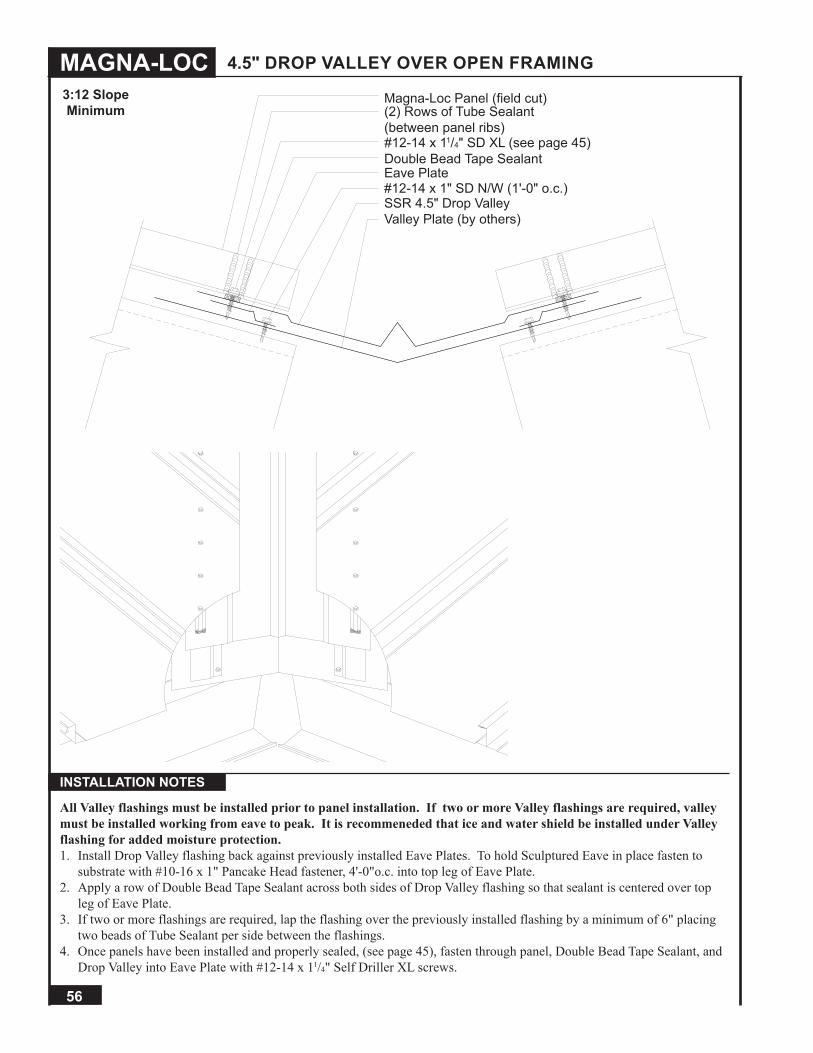
MAGNA-LOC
56
4.5" DROP VALLEY OVER OPEN FRAMING
INSTALLATION NOTES
All Valley flashings must be installed prior to panel installation. If two or more Valley flashings are required, valley must be installed working from eave to peak. It is recommeneded that ice and water shield be installed under Valley flashing for added moisture protection.1. Install Drop Valley flashing back against previously installed Eave Plates. To hold Sculptured Eave in place fasten to
substrate with #10-16 x 1" Pancake Head fastener, 4'-0"o.c. into top leg of Eave Plate.2. Apply a row of Double Bead Tape Sealant across both sides of Drop Valley flashing so that sealant is centered over top
leg of Eave Plate.3. If two or more flashings are required, lap the flashing over the previously installed flashing by a minimum of 6" placing
two beads of Tube Sealant per side between the flashings.4. Once panels have been installed and properly sealed, (see page 45), fasten through panel, Double Bead Tape Sealant, and
Drop Valley into Eave Plate with #12-14 x 11/4" Self Driller XL screws.
Magna-Loc Panel (field cut)(2) Rows of Tube Sealant(between panel ribs)
Double Bead Tape Sealant
SSR 4.5" Drop Valley
Eave Plate#12-14 x 1" SD N/W (1'-0" o.c.)
#12-14 x 11/4" SD XL (see page 45)
Valley Plate (by others)
3:12 SlopeMinimum

57
9" DROP VALLEY OVER OPEN FRAMING 3:12 SlopeMinimum
INSTALLATION NOTES
All Valley flashings must be installed prior to panel installation. If two or more Valley flashings are required, valley must be installed working from eave to peak. It is recommeneded that ice and water shield be installed under Valley flashing for added moisture protection.1. Install Drop Valley flashing back against previously installed Eave Plates, (see page 44). To hold Sculptured Eave in
place fasten to substrate with #10-16 x 1" Pancake Head fastener, 4'-0"o.c. into top leg of Eave Plate.2. Apply a row of Double Bead Tape Sealant across both sides of the Drop Valley flashing so that the sealant is centered over
the top leg of the Eave Plate.3. If two or more flashings are required, lap the flashing over the previously installed flashing by a minimum of 6" placing
two beads of Tube Sealant per side between the flashings.4. Once panels have been installed and properly sealed, (see page 45), fasten through panel, Double Bead Tape Sealant, and
Drop Valley into Eave Plate with #12-14 x 11/4" Self Driller XL screws.
Magna-Loc Panel (field cut)(2) Rows of Tube Sealant (between panel ribs)
Double Bead Tape Sealant
SSR 9" Drop Valley
Eave Plate#12-14 x 1" SD N/W (1'-0" o.c.)
#12-14 x 11/4" SD XL (see page 45)
Valley Plate (by others)

MAGNA-LOC
58
ENDLAP OVER OPEN FRAMING
INSTALLATION NOTES
1. Once eave panel has been installed, (see page 47), slide a Back-Up Channel under upper edge of panels. Back-UpChannel should be flush with edge of Magna-Loc eave panel. Use C-clamps to hold Back-Up Channel in place.
2. Apply a row of Endlap Pads across flat pans, up and over all ribs of eave panels. Endlap Pad should be flush with edge ofeave panel.
3. Roll Magna-Loc peak panel into place and nest with eave panel so that 2" factory notch is completely covered. (See page47 for complete details on installing lapped panels.)
4. With peak panel in place, fasten panel endlap with (5) #12-14 x 11/4" SD XL fasteners per panel through factory punchedholes and into the Back-Up Channel.
5. Apply a pig tail of Endlap Pad, approximately 2½", over factory notched section of male legs.
Magna-Loc Peak Panel (factory pre-punched)
2" (Panel Notch)
Endlap Pad
#12-14 x 11/4" SD XL (see below)
Magna-Loc Eave Panel (factory notch)Back-up Channel
Pigtail of Endlap Pad
#12-14 x 11/4" SD XL13 25 4
FASTENING PATTERN
8"
1/2:12 SlopeMinimum

59
SSR SCULPTURED RAKE (ON MODULE)
INSTALLATION NOTESMagna-Loc floating rake zee and Magna-Loc panels must be installed prior to SSR Sculptured Rake installation (See pages 43-53).1. With Magna-Loc panel properly nested over top of Magna-Loc Floating Rake Zee, apply a row of Double Bead Tape
Sealant across upper side of panel rib.2. Install SSR Rake Cleat over Double Bead Tape Sealant. Fasten through SSR Rake Cleat, Tape Sealant, panel, and into
Floating Rake Zee with #12-14 x 11/4" Self Driller XL screws, 1'-0"o.c.3. Apply a row of Double Bead Tape Sealant across top leg of SSR Rake Cleat.4. Install SSR Sculptured Rake flashing so that top of flashing is flush with top of SSR Rake Cleat and panel rib. Fasten
through SSR Sculptured Rake, Tape Sealant, and into SSR Rake Cleat with ¼"-14 x 7/8" Stitch XL, 1'-0"o.c.5. Position and apply a row of Double Bead Tape Sealant across wall panel just below lower leg of SSR Rake Flashing.6. Install SSR Rake Slide over lower leg of SSR Rake flashing and Double Bead Tape Sealant. Fasten with ¼"-14 x 7/8"
Stitch XL, 1'-0"o.c.7. If two or more flashings are required, lap the flashing over the previously installed flashing by a minimum of 2" placing a
bead of Tube Sealant between the flashings and securing with Pop Rivets, 2.5"o.c.
Magna-Loc Panel
Rake Angle (by others)
1/4"-14 x 7/8" Stitch XL (1'-0" o.c.)
SSR Sculptured Rake (off module)
Double Bead Tape Sealant
Floating Rake Zee#12-14 x 11/4" SD XL (1'-0" o.c.)
1/4"-14 x 11/4" Shoulder SD (1'-0" o.c.)
SSR Rake Slide1/4"-14 x 7/8" Stitch XL (1'-0" o.c.)
Double Bead Tape Sealant
SSR Rake Cleat
1/2:12 SlopeMinimum

MAGNA-LOC
60
SSR SCULPTURED RAKE (OFF MODULE)
INSTALLATION NOTES
Magna-Loc Floating Rake Zee and Magna-Loc panels must be installed prior to SSR Sculptured Rake installation (See Pages 43-53).1. With Magna-Loc panel nested against Magna-Loc Floating Rake Zee, apply a row of Double Bead Tape sealant across
upper side of field bent panel rib. (See page 51 for proper bending of panel.)2. Install SSR Rake Cleat over Double Bead Tape Sealant. Fasten through SSR Rake Cleat, Tape Sealant, panel, and into
Floating Rake Zee with #12-14 x 11/4" Self Driller XL screws, 1'-0"o.c.3. Apply a row of Double Bead Tape Sealant across top leg of SSR Rake Cleat.4. Install SSR Sculptured Rake flashing so that top of flashing is flush with top of SSR Rake Cleat and panel rib. Fasten
through SSR Sculptured Rake, Tape Sealant, and into SSR Rake Cleat with ¼"-14 x 7/8" Stitch XL, 1'-0"o.c.5. Position and apply a row of Double Bead Tape Sealant across wall panel just below lower leg of SSR Rake flashing.6. Install SSR Rake Slide over lower leg of SSR Rake flashing and Double Bead Tape Sealant. Fasten with ¼"-14 x 7/8"
Stitch XL, 1'-0"o.c.7. If two or more flashings are required, lap the flashing over the previously installed flashing by a minimum of 2" placing a
bead of Tube Sealant between the flashings and securing with Pop Rivets, 2.5"o.c.
Magna-Loc Panel (field cut and bend)
Rake Angle (by others)
1/4"-14 x 7/8" Stitch XL (1'-0" o.c.)
SSR Sculptured Rake (off module)
Double Bead Tape SealantSSR Rake Cleat
Floating Rake Zee#12-14 x 11/4" SD XL (1'-0" o.c.)
1/4"-14 x 11/4" Shoulder SD (1'-0" o.c.)
SSR Rake Slide1/4"-14 x 7/8" Stitch XL (1'-0" o.c.)
Double Bead Tape Sealant
2"
Closure (by others)
CAUTIONNote: If panel does termi-nate on module then Rake
Cleat is not needed.
1/2:12 SlopeMinimum

61
INSTALLATION NOTES
RAKEWALL (ON MODULE)
Magna-Loc Floating Rake Zee and Magna-Loc Panels must be installed prior to Rakewall installation (See pages 43-53).1. With Magna-Loc panel properly nested over top of Magna-Loc Floating Rake Zee, apply a row of Double Bead Tape
Sealant across upper side of panel rib.2. Install SSR Rake Cleat over Double Bead Tape Sealant. Fasten through SSR Rake Cleat, Tape Sealant, panel, and into
Floating Rake Zee with #12-14 x 11/4" Self Driller XL screws, 1'-0"o.c.3. Apply a row of Double Bead Tape Sealant across top leg of SSR Rake Cleat.4. Install SSR Rakewall so that top of flashing is flush with top of SSR Rake Cleat and panel rib. Fasten through SSR
Rakewall, Tape Sealant, and into SSR Rake Cleat with ¼"-14 x 7/8" Stitch XL, 1'-0"o.c.5. Install Counter Flashing, Reglet, or wall panel and fasten to parapet wall with appropriate fastener, 12"o.c. If Counter
Flashing or Reglet is used, seal to parapet wall with Tube Sealant. Do NOT fasten SSR Rakewall to parapet wall.6. If two or more flashings are required, lap the flashing over the previously installed flashing by a minimum of 2" placing a
bead of Tube Sealant between the flashings and securing with Pop Rivets, 2.5"o.c.
Rake Angle (by others)
1/4"-14 x 7/8" Stitch XL (1'-0" o.c.)SSR Rakewall
Double Bead Tape SealantSSR Rake Cleat
Floating Rake ZeeMagna-Loc Panel
Tube Sealant
#12-14 x 11/4" SD XL (1'-0" o.c.)
1/4"-14 x 11/4" Shoulder SD (1'-0" o.c.)
Fastener (by others)Counter Flashing
17/8"
1/2:12 SlopeMinimum

MAGNA-LOC
62
RAKEWALL (OFF MODULE)
INSTALLATION NOTES
Magna-Loc Floating Rake Zee and Magna-Loc Panels must be installed prior to Rakewall installation (See pages 43-53).1. With Magna-Loc panel nested against Magna-Loc Floating Rake Zee, apply a row of Double Bead Tape Sealant across
upper side of field bent panel rib. (See page 51 for proper bending of panel.)2. Install SSR Rake Cleat over Double Bead Tape Sealant. Fasten through SSR Rake Cleat, tape sealant, panel, and into
floating rake zee with #12-14 x 11/4" Self Driller XL screws, 1'-0"o.c.3. Apply a row of Double Bead Tape Sealant across top leg of SSR Rake Cleat.4. Install SSR Rakewall so that top of flashing is flush with top of SSR Rake Cleat and panel rib. Fasten through SSR
Rakewall, tape sealant, and into SSR Rake Cleat with ¼"-14 x 7/8" Stitch XL, 1'-0"o.c.5. Install Counter Flashing, Reglet, or wall panel and fasten to parapet wall with appropriate fastener, 12"o.c. If Counter
Flashing or Reglet is used, seal to parapet wall with tube sealant. Do NOT fasten SSR Rakewall to parapet wall.6. If two or more flashings are required, lap the flashing over the previously installed flashing by a min. of 2" placing a bead
of Tube Sealant between the flashings and securing with Pop Rivets, 2.5"o.c.
17/8"
Rake Angle (by others)
1/4"-14 x 7/8" Stitch XL (1'-0" o.c.)
SSR Rakewall
Double Bead Tape Sealant
SSR Rake Cleat
Floating Rake Zee
Magna-Loc Panel (field cut and bend)
Tube Sealant
#12-14 x 11/4" SD XL (1'-0" o.c.)
1/4"-14 x 11/4" Shoulder SD (1'-0" o.c.)
Reglet Flashing
1/2:12 SlopeMinimum

63
EXPANSION JOINT OVER OPEN FRAMING
INSTALLATION NOTES
Magna-Loc Floating Rake Zees and Magna-Loc Panels must be installed prior to Expansion Joint installation (See pages 43-53).1. With Magna-Loc panels nested against Magna-Loc Floating Rake Zees, apply a row of Double Bead Tape Sealant across
upper side of panel ribs on both sides of Expansion Joint. (See page 51 for proper bending of panel if off module.)2. Install SSR Rake Cleats over Double Bead Tape Sealant on both sides. Fasten through SSR Rake Cleat, Tape Sealant,
panel, and into Floating Rake Zee with #12-14 x 11/4" Self Driller XL screws, 1'-0"o.c. on both sides of Expansion Joint.3. Apply a row of Double Bead Tape Sealant across top leg of SSR Rake Cleats.4. Install Expansion Joint flashing on top legs of SSR Rake Cleats. Fasten through Expansion Joint flashing, Tape Sealant,
and into SSR Rake Cleat with ¼"-14 x 7/8" Stitch XL, 1'-0"o.c. on both sides of Expansion Joint.5. If two or more flashings are required, lap the flashing over the previously installed flashing by a minimum of 2" placing a
bead of Tube Sealant between the flashings and securing with Pop Rivets, 2.5"o.c.
Double Bead Tape Sealant
Expansion JointMagna-Loc Panel (field cut and bend)
Floating Rake Zee1/4"-14 x 11/4" Shoulder SD (1'-0" o.c.)
2"
1/4"-14 x 7/8" Stitch XL
SSR Rake Cleat#12-14 11/4" SD XL (1'-0" o.c.)
Rake Angle (by others)

MAGNA-LOC
64
ENDWALL WITH WALL PANEL
INSTALLATION NOTES
1. Once panels have been installed, slide Back-Up Channel under upper edge of panels. Position Back-Up Channel to allowfor proper installation of endwall assembly. Use C-clamps to hold Back-Up Channel in place.
2. Apply a row of Double Bead Tape Sealant across panel, up and over all ribs approximately 6"-8" from panel end.3. Install Magna-Loc End Dams over Tape Sealant. Before continuing make sure End Dam placement will accommodate
SSR High Side Pitch Break.4. Once closure is set in Tape Sealant, fasten through End Dam, Tape Sealant, Magna-Loc panel, and into Back-Up Channel
with (5) #12-14 x 1" SD N/W per panel. C-clamps may be removed once closures have been fastened.5. Once all End Dams have been installed, place a row of Double Bead Tape Sealant across top of End Dams. Tube Sealant
must be used to fill any and all gaps left around End Dams.6. Install SSR High Side Pitch Break and secure to top leg of End Dams with ¼"-14 x 7/8" Stitch XL at the spacing shown
above and to parapet wall with appropriate fastener, 12"o.c.7. Install Counter Flashing, Reglet, or wall panel and fasten to parapet wall with appropriate fastener, 12"o.c. If Counter
Flashing or Reglet is used, seal to parapet wall with Tube Sealant.8. If two or more flashings are required, lap the flashing over the previously installed flashing by a minimum of 2" placing a
bead of Tube Sealant between the flashings and securing with Pop Rivets, 2.5"o.c.
Clip W/ 1/4"-14 x 11/2" SD N/W
1/4"-14 x 7/8" Stitch XL (3 per panel)
SSR High Side Pitch Break
Back-up Channel
#12-14 x 1" SD N/W (see below)
Double Bead Tape SealantEnd Dam or Z-Closure
Fastener (by others)
Magna-Loc Panel
8" MIN
2"
#12-14 x 1" SD NW13 25 4
FASTENING PATTERN
1/2:12 Slope Minimum using End Dam3:12 Slope Minimum using Z-Closure

65
SCULPTURED HIGH SIDE EAVE
INSTALLATION NOTES
1. Once panels have been installed, slide Back-Up Channel under upper edge of panels. Position Back-Up Channel to allowfor proper installation of High Side Eave assembly. Use C-clamps to hold Back-Up Channel in place.2. Apply a row of Double Bead Tape Sealant across panel, up and over all ribs approximately 2"-4" from panel end.3. Install Magna-Loc End Dams over tape sealant. Before continuing make sure End Dam placement will accommodate SSRSculptured High Side Eave flashing.4. Once Closure is set in Tape Sealant, fasten through End Dam, Tape Sealant, Magna-Loc panel, and into Back-Up Channelwith (5) #12-14 x 1" SD N/W per panel. C-clamps may be removed once closures have been fastened.5. Once all End Dams have been installed, place a row of Double Bead Tape Sealant across top of End Dams. Tube Sealantmust be used to fill any and all gaps left around End Dams.6. Install SSR Sculptured High Side Eave flashing and secure to top leg of End Dams with ¼"-14 x 7/8" Stitch XL at thespacing shown above.7. Fasten SSR Sculptured High Side Eave flashing to finished wall with appropriate fastener, 1'-0"o.c.8. If two or more flashings are required, lap the flashing over the previously installed flashing by a minimum of 2" placing abead of Tube Sealant between the flashings and securing with Pop Rivets, 2.5"o.c.
Clip W/ (2) 1/4"-14 x 11/2" SD N/W
SSR Sculptured High Side Eave
1/4"-14 x 7/8" Stitch XL (3 per panel)
Magna-Loc Panel (field cut)
Back-up Channel#12-14 x 1" SD N/W (see below)
Double Bead Tape SealantEnd Dam or Z-Closure
1/4"-14 x 7/8" Stitch XL (1'-0" o.c.)Double Bead Tape Sealant
31/2"
#12-14 x 1" SD NW13 25 4
FASTENING PATTERN
1/2:12 Slope Minimum using End Dam3:12 Slope Minimum using Z-Closure

MAGNA-LOC
66
SSR RIDGE OVER OPEN FRAMING
INSTALLATION NOTES
1. Once panels have been installed, slide Back-Up Channel under upper edge of panels. Position Back-Up Channel to allowfor proper installation of ridge assembly. Use C-clamps to hold Back-Up Channel in place.
2. Apply a row of Double Bead Tape Sealant across panel, up and over all ribs approximately 2"-4" from panel end on bothsides of ridge.
3. Install Magna-Loc End Dams over Tape Sealant. Before continuing make sure End Dam placement will accommodateSSR Ridge.
4. Once Closure is set in Tape Sealant, fasten through End Dam, Tape Sealant, Magna-Loc panel, and into Back-Up Channelwith (5) #12-14 x 1" SD N/W per panel. C-clamps may be removed once Closures have been fastened.
5. Once all End Dams have been installed, place a row of Double Bead Tape Sealant across top of End Dams on both sidesof ridge. Tube Sealant must be used to fill any and all gaps left around End Dams.
6. Install SSR Ridge flashing and secure to top leg of End Dams with ¼"-14 x 7/8" Stitch XL at the spacing shown above.7. If two or more flashings are required, lap the flashing over the previously installed flashing by a minimum of 2" placing a
bead of Tube Sealant between the flashings and securing with Pop Rivets, 2.5"o.c.
Double Bead Tape Sealant
Clip W/ (2) 1/4"-14 x 11/2" SD N/W
SSR Ridge
1/4"-14 x 7/8" Stitch XL (3 per panel)Magna-Loc Panel
Back-up Channel
CL
1'-0"
3"
End Dam or Z-Closure#12-14 x 1" SD N/W (see below)
#12-14 x 1" SD NW13 25 4
FASTENING PATTERN
1/2:12 Slope Minimum using End Dam3:12 Slope Minimum using Z-Closure

67
RIDGE / HIP
INSTALLATION NOTES
1. Once panels have been installed, slide Back-Up Channel under upper edge of panels. Position Back-Up Channel to allowfor proper installation of hip assembly. Use C-Clamps to hold Back-Up Channel in place.
2. Apply a row of Double Bead Tape Sealant across panel, up and over all ribs approximately 2"-4" from panel end on bothsides of hip.
3. Install field cut Z-Closure over tape sealant. (See page 79 for preparing Z-Closures.) Before continuing make sureZ-Closure placement will accommodate 20" Hip Cover flashing.
4. Once Closure is set in Tape Sealant, fasten through Z-Closure, Tape Sealant, Magna-Loc panel, and into Back-Up Channelwith (5) #12-14 x 1" SD N/W per panel. C-clamps may be removed once Closures have been fastened.
5. Once all Z-Closures have been installed, place a row of Double Bead Tape Sealant across top of Closures on both sides of20" Hip Cover. Tube Sealant must be used to fill any and all gaps left around Z-Closures.
6. Install 20" Hip Cover flashing and secure to top leg of Z-Closure with ¼"-14 x 7/8" Stitch XL at the spacing shown above.7. If two or more flashings are required, lap the flashing over the previously installed flashing by a minimum of 2" placing a
bead of Tube Sealant between the flashings and securing with Pop Rivets, 2.5"o.c.
Double Bead Tape Sealant
Clip W/ (2) 1/4"-14 x 11/2" SD N/W
20" Hip Cover
1/4"-14 x 7/8" Stitch XL (3 per panel)
Magna-Loc Panel (field cut)
Back-up Channel
Z-Closure (field cut) or End Dam#12-14 x 1" SD N/W (see below)
#12-14 x 1" SD NW13 25 4
FASTENING PATTERN
For Ridge:1/2:12 Slope Minimum using End Dam3:12 Slope Minimum using Z-ClosureFor Hip:1/2:12 Slope Minimum using End Damor Z-Closure(recommended)

MAGNA-LOC
68
VENTED RIDGE OVER OPEN FRAMING
INSTALLATION NOTES
1. Once panels have been installed, slide Back-Up Channel under the upper edge of panels. Position Back-Up Channel toallow for proper installation of vented ridge assembly. Use C-clamps to hold Back-Up Channel in place.
2. Apply a row of Double Bead Tape Sealant across panel, up and over all ribs approximately 0"-2" from panel end on bothsides of ridge.
3. Install Magna-Loc End Dams over Tape Sealant. Before continuing make sure End Dam placement will accommodateVented Ridge Cover.
4. Once closure is set in Tape Sealant, fasten through End Dam, Tape Sealant, Magna-Loc panel, and into Back-Up Channelwith (5) #12-14 x 1" SD N/W per panel. C-clamps may be removed once Closures have been fastened.
5. Once all End Dams have been installed, place a row of Double Bead Tape Sealant across top of End Dams on both sides ofridge. Tube Sealant must be used to fill any and all gaps left around End Dams.
6. Install Vent Drip, Vent Material, and Offset Cleat (in order) and fasten to top leg of End Dam with #14 Dekfasts at 1'-0"o.c.7. Apply a row of Double Bead Tape Sealant across outer leg of Offset Cleat.8. Install Vented Ridge Cover and secure to outer leg of Offset Cleat with Pop Rivets at 1'-0"o.c.9. If two or more flashings are required, lap the flashing over the previously installed flashing by a minimum of 2" placing a
bead of Tube Sealant between the flashings and securing with Pop Rivets 2.5"o.c.
Double Bead Tape Sealant
Clip W/ (2) 1/4"-14 x 11/2" SD N/W
Vented Ridge Cover
Magna-Loc Panel
Vent Material
End Dam or Z-Closure
#12-14 x 1" SD N/W (see below)
1/8" x 3/16" Pop Rivet (1'-0" o.c.)
#14-13 x 2" Deck Screw (1'-0" o.c.)
Vent DripOffset Cleat
Back-up Channel
1'
CL
1"
#12-14 x 1" SD NW13 25 4
FASTENING PATTERN
1/2:12 Slope Minimum using End Dam3:12 Slope Minimum using Z-Closure

69
EAVE OFFSET OVER DECKING
Double Bead Tape Sealant
#10-12 x 1" PHW (1'-0" o.c.)
Magna-Loc Panel
Moisture Barrier (by others)
Offset Cleat
Eave
Tube Sealant (between panel ribs)
Cleat
Tube Sealant
#10-12 x 1" PHW (1'-0" o.c.)
INSTALLATION NOTES
All Eave flashings must be installed prior to panel installation.1. Position and install Cleat to wall with appropriate fastener, 12"o.c. Make sure Cleat allows for proper Eave attachment.2. Install Eave flashing by sliding open hem onto Cleat and resting the Eave flashing back against substrate. To hold Eave
flashing in place fasten to substrate with #10-12 x 1" Pancake Head fastener, 4'-0"o.c.3. Apply a row of Double Bead Tape Sealant across Eave flashing approximately 2"-3" from face of Eave flashing.4. Properly align and install Offset Cleat so that Magna-Loc panel will be flush with Eave flashing. Fasten through Offset
Cleat, Tape Sealant, Eave Flashing and into substrate with Pancake Head fastener at 1'-0"o.c.5. Apply a continuous bead of Tube Sealant along outer edge of Offset Cleat in panel hem.6. If two or more flashings are required, lap the flashing over the previously installed flashing by a minimum of 2" placing a
bead of Tube Sealant between the flashings and securing with Pop Rivets, 2.5"o.c.7. Install Magna-Loc panel by engaging field hemmed panel end (see page 82) over Offset Cleat. Two beads of Tube
Sealant must be applied up and over male leg of each Magna-Loc panel during panel installation (see page 49).
1/2:12 SlopeMinimum

MAGNA-LOC
70
BOX GUTTER OFFSET OVER DECKING
Double Bead Tape Sealant
Magna-Loc Panel
Moisture Barrier (by others)
Offset CleatTube Sealant (between panel ribs)
1/8" x 3/16" Pop Rivet (1 per strap)Box Gutter
#10-12 x 1" PHW (1'-0" o.c.)
Tube Sealant
Universal Gutter/Downspout Strap
INSTALLATION NOTES
All Gutter flashings must be installed prior to panel installation.1. Install Box Gutter flashing back against substrate. To hold Box Gutter flashing in place fasten to substrate with #10-12x1"
Pancake Head fastener, 4'-0"o.c.2. Install Universal Gutter/Downspout Straps every 3'-0" of gutter length. Fasten to Box Gutter under front lip with Pop
Rivets.3. Apply a row of Double Bead Tape Sealant across Box Gutter flashing approximately 2"-3" from inside of Box Gutter
flashing.4. Properly align and install Offset Cleat so that Magna-Loc panel will be flush with inside of Box Gutter flashing. Fasten
through Offset Cleat, Tape Sealant, Universal Gutter Strap, Box Gutter and into substrate with Pancake Head fastener1'-0"o.c. Fastener must pass through Universal Gutter Downspout Strap.
5. If two or more flashings are required, lap the flashing over the previously installed flashing by a minimum of 2" placing ahead of Tube Sealant between the flashings and securing with Pop Rivets, 2.5"o.c.
6. Install Magna-Loc panel by engaging field hemmed panel end (see page 82) over Offset Cleat. Two beads of Tube Sealantmust be applied up and over male leg of each Magna-Loc panel during panel installation (see page 49).
CAUTIONIn locations where heavy rainfall or severe ice and
snow may occur, standard gutters may not be suitable
for use.
1/2:12 SlopeMinimum

71
VALLEY OFFSET OVER DECKING Magna-Loc Panel
Moisture Barrier (by others)
Offset Cleat
Valley
Double Bead Tape Sealant
3" MIN.
Tube Sealant (between panel ribs)Tube Sealant
#10-12 x 1" PHW (1'-0" o.c.)
INSTALLATION NOTES
Valley flashing must be installed working from eave to peak if two or more flashings are required. It is recommended that an ice and water shield be placed along the valley beneath the flashing for added protection against moisture.1. Install Valley flashing back against substrate. To hold Valley flashing in place fasten to substrate with #10-12 x 1" Pancake
Head fastener, 4'-0"o.c.2. If two or more flashings are required, lap the flashing over the previously installed flashing by a minimum of 2" placing a
bead of Tube Sealant between the flashings and securing with Pop Rivets, 2.5"o.c.3. Place a continuous row of Double Bead Tape Sealant across bottom leg of Offset Cleat and apply to both sides of valley.4. Fasten through Offset Cleat, Tape Sealant, Valley flashing and into substrate with Pancake Head fastener, 1'-0"o.c.5. Install Magna-Loc panel by engaging field hemmed panel end (see page 82) over Offset Cleat. Two beads of Tube Sealant
must be applied up and over male leg of each Magna-Loc panel during panel installation (see page 49).
3:12 SlopeMinimum

MAGNA-LOC
72
Double Bead Tape Sealant
#10-12 x 1" PHW (1' o.c.)
Cleat
SSR Rake Cleat
Rake
Magna-Loc Panel
1/4"-14 x 7/8" Stitch XL (1' o.c.)
RAKE (ON MODULE) OVER DECKING
1/4"-14 x 11/4" Shoulder SD (1' o.c.)
#12-14 x 11/4" SD XL (1' o.c.)
Magna-Loc Rake Zee
1/2:12 SlopeMinimum
INSTALLATION NOTES
Magna-Loc Floating Rake Zee and Magna-Loc panels must be installed prior to rake installation (see pages 43-53).1. Position and install Cleat to wall with appropriate fastener, 12"o.c. Make sure Cleat installation allows for proper Rake
attachment.2. With Magna-Loc panel properly nested and fastened against Floating Rake Zee, apply a row of Double Bead Tape Sealant
across top of panel rib.3. Install Rake flashing by sliding open hem onto Cleat and resting the Rake flashing on top of panel rib. Fasten through
Rake, Sealant, and into Floating Rake Zee with ¼"-14 x 7/8" Stitch XL, 12"o.c.4. If two or more flashings are required, lap the flashing over the previously installed flashing by a minimum of 2" placing a
bead of Tube Sealant between the flashings and securing with Pop Rivets 2.5"o.c.

73
RAKE (OFF MODULE) OVER DECKING
Double Bead Tape Sealant
#10-12 x 1" PHW
Cleat
SSR Rake Cleat
Rake
Magna-Loc Panel
1/4"-14 x 7/8" Stitch XL (1' o.c.)
1/4"-14 x 11/4" Shoulder SD
Floating Rake Zee
Moisture Barrier (by others)
INSTALLATION NOTES
Magna-Loc Floating Rake Zee and Magna-Loc panels must be installed prior to rake installation (see pages 43-53).1. Position and install Cleat to wall with appropriate fastener, 12"o.c. Make sure Cleat installation allows for proper Rake
attachment.2. With Magna-Loc panel properly nested and fastened against Floating Rake Zee, apply a row of Double Bead Tape Sealant
across top of panel rib.3. Install Rake flashing by sliding open hem onto Cleat and resting the Rake flashing on top of panel rib. Fasten through
Rake, Sealant, and into Floating Rake Zee with ¼"-14 x 7/8" Stitch XL, 12"o.c.4. If two or more flashings are required, lap the flashing over the previously installed flashing by a minimum of 2" placing a
bead of Tube Sealant between the flashings and securing with Pop Rivets 2.5"o.c.
#12-14 x 11/4" SD XL (1' o.c.)
1/2:12 SlopeMinimum

MAGNA-LOC
74
RAKEWALL OVER DECKING
INSTALLATION NOTES
Magna-Loc Floating Rake Zee and Magna-Loc Panels must be installed prior to Rakewall installation (See pages 43-53).1. With Magna-Loc panel nested against Magna-Loc Floating Rake Zee, apply a row of Double Bead Tape Sealant across
upper side of field bent panel rib. (See page 51 for proper bending of panel.)2. Install SSR Rake Cleat over Double Bead Tape Sealant. Fasten through SSR Rake Cleat, Tape Sealant, panel, and into
Floating Rake Zee with #12-14 x 1¼" Self Driller XL screws, 1'-0"o.c.3. Apply a row of Double Bead Tape Sealant across top leg of SSR Rake Cleat.4. Install SSR Rakewall so that top of flashing is flush with top of SSR Rake Cleat and panel rib. Fasten through SSR
Rakewall, Tape Sealant, and into SSR Rake Cleat with ¼"-14 x 7/8" Stitch XL, 1'-0"o.c.5. Install Counter Flashing, Reglet, or wall panel and fasten to parapet wall with appropriate fastener, 12"o.c. If Counter
Flashing or Reglet is used, seal to parapet wall with tube sealant. Do NOT fasten SSR Rakewall to parapet wall.6. If two or more flashings are required, lap the flashing over the previously installed flashing by a minimum of 2" placing a
bead of Tube Sealant between the flashings and securing with Pop Rivets, 2.5"o.c.
Double Bead Tape Sealant
SSR Rakewall
Magna-Loc Panel
1/4"-14 x 7/8" Stitch XL (12"o.c.)
1/4"-14 x 11/4" Shoulder SD (1'-0" o.c.)
#12-14 x 11/4" SD XL
Floating Rake Zee
Wall Panel (by others)
SSR Rake Cleat
1/2:12 SlopeMinimum

75
PEAK WITH END DAM OVER DECKING
INSTALLATION NOTES
Magna-Loc Eave Plate and Magna-Loc panels must be installed prior to peak installation (see page 44).1. Once panels have been installed and properly sealed, (see page 45) apply a row of Double Bead Tape Sealant across panel,
up and over all ribs approximately 2"-4" from panel end.2. Install Magna-Loc End Dams over Tape Sealant. Before continuing make sure End Dam placement will accommodate
Peak Flashing.3. Once closure is set in Tape Sealant, fasten through End Dam, Double Bead Tape Sealant, Magna-Loc panel, and into Eave
Plate with (5) #12-14x1" SD N/W per panel.4. Once all End Dams have been installed, place a row of Double Bead Tape Sealant across top of End Dams. Tube sealant
must be used to fill any and all gaps left around End Dams.5. Position and install Cleat to wall with appropriate fastener, 12"o.c. Make sure Cleat allows for proper Peak attachment.6. Install Peak flashing by sliding open hem onto Cleat and resting the Peak flashing back over End Dams. Secure to top leg
of End Dams with ¼"-14 x 7/8" Stitch XL at the spacing shown above.7. If two or more flashings are required, lap the flashing over the previously installed flashing by a minimum of 2" placing a
bead of Tube Sealant between the flashings and securing with Pop Rivets, 2.5"o.c.
Double Bead Tape Sealant
#10-12" x 1" PHW (1'-0" o.c.)
Cleat
End Dam or Z-Closure
Magna-Loc Panel
1/4"-14 x 7/8" Stitch XL (3 per panel)
Floating Clip W/ (2) #12-11 x 11/4" LPWS
Moisture Barrier (by others)
#10-12 x 1" PHW
#12-14 x 1" SD N/W (see below)
Peak
#12-14 x 1" SD NW13 25 4
FASTENING PATTERN
1/2:12 Slope Minimum using End Dam3:12 Slope Minimum using Z-Closure

MAGNA-LOC
76
RIDGE / HIP - FIXED
INSTALLATION NOTES
Magna-Loc Eave Plate and Magna-Loc panels must be installed prior to Ridge/Hip installation (see pages 43-53).1. Once panels have been installed and properly sealed, (see page 45) apply a row of Double Bead Tape Sealant across panel,
up and over all ribs approximately 2"-4" from panel end on both sides of ridge/hip.2. For a ridge, install Magna-Loc End Dams over Tape Sealant. For a hip, install a field cut Z-Closure over Tape Sealant
(see page 79 for preparing Z-Closures). Before continuing make sure End Dam placement will accommodate 20" HipCover.
3. Once Closure is set in Tape Sealant, fasten through End Dam, Tape Sealant, Magna-Loc panel, and into Eave Plate with(5) #12-14 x 1" SD N/W per panel.
4. Once all End Dams have been installed, place a row of Double Bead Tape Sealant across top of End Dams on both sidesof 20" Hip Cover. Tube Sealant must be used to fill any and all gaps left around End Dams.
5. Install 20" Hip Cover flashing and secure to top leg of End Dams with ¼"-14 x 7/8" Stitch XL at the spacing shown above.6. If two or more flashings are required, lap the flashing over the previously installed flashing by a minimum of 2" placing a
bead of Tube Sealant between the flashings and securing with Pop Rivets 2.5"o.c.
Double Bead Tape Sealant#12-14 x 1" SD N/W (see below)
Z-Closure (field cut) or End Dam
Magna-Loc Panel1/4"-14 x 7/8" Stitch XL (3 per panel)
Floating Clip W/ (2) #12-11 x 11/4" LPWS
Moisture Barrier (by others)
#10-12 x 1" PHW (1' o.c.)
20" Hip Cover
#12-14 x 1" SD NW13 25 4
FASTENING PATTERN
Eave Plate
For Ridge:1/2:12 Slope Minimum using End Dam3:12 Slope Minimum using Z-ClosureFor Hip:1/2:12 Slope Minimum using End Damor Z-Closure(recommended)

77
VENTED RIDGE OVER DECKING
INSTALLATION NOTES
Magna-Loc Eave Plate and Magna-Loc panels must be installed prior to Vented Ridge installation (see pages 43-53).1. Once panels have been installed, slide Back-Up Channel under upper edge of panels. Position Back-Up Channel to allow
for proper installation of vented ridge assembly. Use C-clamps to hold Back-Up Channel in place.2. Apply a row of Double Bead Tape Sealant across panel, up and over all ribs approximately 0"-2" from panel end on
both sides of ridge.3. Install Magna-Loc End Dams over Tape Sealant. Before continuing make sure End Dam placement will accommodate
Vented Ridge Cover.4. Once closure is set in Tape Sealant, fasten through End Dam, Tape Sealant, Magna-Loc panel, and into Back-Up Channel
with (5) #12-14 x 1" SD N/W per panel. C-clamps may be removed once Closures have been fastened.5. Once all End Dams have been installed, place a row of Double Bead Tape Sealant across top of End Dams on both sides of
ridge. Tube Sealant must be used to fill any and all gaps left around End Dams.6. Install Vent Drip, Vent Material, and Offset Cleat (in order) and fasten to top leg of End Dam with #14 Dekfasts at 1'-0"o.c.7. Apply a row of Double Bead Tape Sealant across outer leg of Offset Cleat.8. Install Vented Ridge Cover and secure to outer leg of Offset Cleat with Pop Rivets at 1'-0"o.c.9. If two or more flashings are required, lap the flashing over the previously installed flashing by a minimum of 2" placing a
bead of Tube Sealant between the flashings and securing with Pop Rivets, 2.5"o.c.
Double Bead Tape Sealant
#12-14 x 1" SD NW
End Dam or Z-Closure
Magna-Loc PanelFloating Clip W/ (2) #12-11 x 11/4" LPWS
Magna-Loc Eave Plate
#10-12 x 1" PHW (1'-0" o.c.)
Vented Ridge Cover
1/8" x 3/16" Pop Rivet (1'-0" o.c.)
#14-13 x 2" Deck Screw (1'-0" o.c.)Offset CleatVent Material
Vent Drip
2" MIN
CL
#12-14 x 1" SD NW13 25 4
FASTENING PATTERN
1/2:12 Slope Minimum using End Dam3:12 Slope Minimum using Z-Closure

MAGNA-LOC
78
INSTALLATION OF END DAM
INSTALLATION NOTES
Note: The End Dam is used to close off the high end of the panel on applications over open framing. Before installation of End Dam can begin, all roof panels must be seamed. (See seaming panels on pages 52 and 53 for proper seaming instructions.)
Steps:1. Apply Double Bead Tape Sealant down the female leg. across the panel and up the male leg 2" from the end of the panel.2. Place the End Dam on Double Bead Tape Sealant making sure the punched lower leg is towards the ridge. The punched
lower leg should be 2" from the end of the panel.3. Slide a Back-Up Channel under the end of the panel and center 2" from the edge of the panel so that the rake end of the
Back-Up Channnel rests on the rake.4. Fasten the End Dam with five (5) #12-14 x 1" SD NW screws or (5) #12-11 x 1 1/2" Low Profile Wood Screws. Fasteners
must penetrate the End Dam, sealant, panel, and Back-Up Channel.5. Apply a continuous 3/8" diameter bead of Tube Sealant (if necessary) where the End Dams meet the panel seams.
Double Bead Tape Sealant(pig-tailed to fill End Dam)
End Dam
Double Bead Tape Sealant
*(Pig-tailed to fill pencil ribs in End Dam)
*Double Bead Tape Sealant
#12-14 x 1" SD NW OR #12-11 x 11/4" LPWS
(5 per panel)
Pre-drilled holes for fastening

79
Z-CLOSURE INSTALLATION
INSTALLATION NOTES
Z-Closure
Field cut and bend back 1"
Double Bead Tape Sealant
Field cut and bend back 1"
1. Place a row of Double Bead Tape Sealant across panel and over each rib approximately 4" from panel end. Beforeproceeding, make sure Z-Closure placement will accomodate flashing.
2. Field cut the Z-Closure 2" longer than the panel width. Snip the top and bottom leg of the Z-Closure and bend both sidesback (as shown above).
3. Fasten through the Z-Closure, Tape Sealant, Magna-Loc panel, and substrate with appropriate fasteners.Note: For Open Framing, the substrate will be the Back-Up Channel shown in the details.
4. Apply a row of Double Bead Tape Sealant across the top of the Z-Closure filling any gaps or openings around the panelribs. This will be fastened through when the flashing is installed.
Slope
#12-14 x 1" SD NWOR #12-11 x 1 #12-11 x 11/4"
1/2:12 Slope Minimum on Hip Condition3:12 Slope Minimum on All Other Conditions

MAGNA-LOC
80
CLIP DETAIL OVER RIGID INSULATION
FLOATING SYSTEM WITH BEARING PLATE
-ISOMETRIC-
Dekfast
FLOATING SYSTEM WITH BEARING PLATE
Rigid InsulationFloating Clip
Bearing Plate
Metal Deck
Magna-Loc Panel
Bearing PlateVapor Barrier

81
TRANSITION DETAIL
Section B-B
Outer Rib CoverInner Rib Cover
Pop RivetMagna-Loc Panel
B-B
Outer Rib CoverInner Rib Cover
Pop RivetMagna-Loc PanelTube Sealant

MAGNA-LOC
82
HEMMING DETAIL
Field Notch Rib
Up to 11/2"
Up to 11/2"
Field bend flat part ofpanel to accept Offset Cleat
Hemming Tool
Field apply sealant in bend and insert Offset Cleat

83
ROOF PENETRATION
Size and location of all roof penetrations should be an important consideration. Areas around roof vents or rooftop units may show that corrosive fumes are emmitted from a process within the building.
NOTE: The following procedures are for vent pipes 6" or less and not transmitting extremely hot or caustic materials. When installing vent pipes abide by the local plumbing codes.
1. Determine the size and length of the vent pipe to be raised.2. Take the appropriate measurements for the vent location and mark them on the Magna-Loc panel. The vent pipe must
extend through the flat of the roof panel. If the vent pipe extension cannot be raised directly into the flat of the new roofpanel, elbows should be used to offset the pipe. Cut the panel to fit the vent pipe properly.
3. Use a light gauge angle to secure and plumb the vent pipe to the framing system.4. Flash the vent pipe with a Rubber Roof Jack or similar pipe flashing.5. Apply Tube Sealant between the panel and the base of the Rubber Roof Jack as well as the top where the boot meets the
pipe.6. Attach the base of the Rubber Roof Jack to the panel using 1/4"-14 x 7/8" Stitch XL fasteners.
GENERAL NOTES
INSTALLATION NOTES
Mini (1/4" to 11/8" O.D. Pipe) #2 (13/4" to 3" O.D. Pipe) #4 (3" to 6" O.D. Pipe) #6 (6" to 9" O.D. Pipe) #8 (7" to 13" O.D. Pipe)
TEMP RANGE: -30° to +250°
Double Bead Tape Sealantand 1/4"-14 x 7/8" Stitch XL
Pipe Vent
Magna-Loc Panel

MAGNA-LOC
84
Though factory applied prepainted finishes are very durable and will last many years, eventually it may be desirable to thor-oughly clean or repaint them.
Dirt pickup may cause apparent discoloration of the paint when it has been exposed in some dirt laded atmospheres for long periods of time. In areas of strong sunlight, slight chalking may cause some change in appearance. A good cleaning will often restore the appearance of these buildings and render repainting unnecessary. An occasional light cleaning will help maintain a good appearance.
In many cases, simply washing the building with plain water using a hose or pressure sprayer will be adequate. In areas where heavy dirt deposits dull the surface, a cloth or soft bristle brush and solution of water and detergent (1/3 cup of laundry detergent per gallon of water for example) may be used. This should be followed by an adequate rinse of water. Do not use wire brushes, abrasives, or cleaning tools which will damage the coating surface.
Mildew may occur in areas subject to high humidity but is not normally a problem due to the high inherent mildew resistance of the baked finish that is used. However, mildew can grow on dirt and spore deposits in some cases. To remove mildew along with the dirt, the following solution is recommended.
1/3 cup detergent (Tide® or equivalent)2/3 cup trisodium phosphate (Solex® or equivalent)1 quart of 5% sodium hypochlorite solution (Clorox® or equivalent)3 quarts of water
Strong solvents and abrasive type cleaners should be avoided. Most organic solvents are flammable and toxic, and must be handled accordingly. When using a solvent, consult maintenance professionals and label instructions for proper handling and disposal of washings. If required, a mild solvent such as mineral spirits can be used to remove caulking compounds, oil, grease, tars, wax, and similar substances. Use a cloth dampened with mineral spirits and apply only to areas which are con-taminated. Follow up the use of this mild solvent with detergent cleaning and rinsing.
CARE AND MAINTENANCE
DO NOT USE A WIRE BRUSH
HOSE OR PRESSURE SPRAY FOR ADEQUATE CLEANING
USE MILD DETERGENT AND WATER FOR HEAVY DIRT DEPOSITS

Metal Roofing, Nationwide
800-728-4010bestbuymetals.com