magnetic-coupled variable speed direct drive
TRANSCRIPT

. . . . . . . . . .
®®
Magnetic-Coupled Variable Speed Direct Drive
“The preferred choice in direct-coupled drive technology.”
4701 Old Denton Road Fort Worth, Texas 76117 817.485.3336 888.557.7873 www.payback.com
Installation, Operation & Maintenance Instructions
V1.1d


3
TABLE OF CONTENTS
FORWARD......................................................................................................................................................... 6
“PRO” PAYBACK® DIRECT-COUPLED DRIVE.................................................................................................... 7
SYSTEM WIRING LAYOUT – “PRO” PAYBACK® DIRECT COUPLED DRIVE ............................................................ 8
INSTALLATION -“PRO” PAYBACK® DIRECT COUPLED DRIVE.............................................................................. 9
SAFETY FIRST ..................................................................................................................................................10
“PRO” PAYBACK® DIRECT COUPLED DRIVES FOR PUMPS................................................................................11
TECHNICAL DATA – “PRO” PAYBACK® DIRECT COUPLED DRIVES ....................................................................12
MOTOR SHAFT TOLERANCE TABLE (NEMA T)....................................................................................................13
ORDERING INFORMATION – “PRO” PAYBACK® DIRECT COUPLED DRIVES..........................................................14
SPEED SENSOR ORIENTATION & INSTALLATION – “PRO” PAYBACK®................................................................15
MANUAL LOCKUP INSTRUCTIONS .......................................................................................................................16
START UP PROCEDURE - “PRO” PAYBACK® DIRECT COUPLED DRIVE ..............................................................18
SIGNAL FOLLOWING MODE SETUP PROCEDURE – “PRO” PAYBACK® ...............................................................19
PRESSURE SET POINT MODE SETUP PROCEDURE – “PRO” PAYBACK® ............................................................20
WARRANTY REGISTRATION FORM – “PRO” PAYBACK® ...................................................................................21
ETL-AC1/AC2 SCHEMATIC – PRO PAYBACK®...............................................................................................22
DRIVE PARTS LIST – “PRO” PAYBACK® (PG 1 OF 3)........................................................................................23
DRIVE PARTS LIST – “PRO” PAYBACK® (PG 2 OF 3)........................................................................................24
DRIVE PARTS LIST – “PRO” PAYBACK® (PG 3 OF 3)........................................................................................25

4
IIMMPPOORRTTAANNTT ONLY QUALIFIED PERSONNEL SHOULD PERFORM INSTALLATION AND SERVICE OF THIS PRODUCT.
This PAYBACK® variable speed drive has been certified by Coyote Electronics, Inc. to be constructed with the highest quality components, has been operated under load, and has passed Q.C. and in-house testing. Observe all applicable national and local electrical codes and safety precautions for rotating equipment, including those stated below.
• READ ALL INSTALLATION INSTRUCTIONS THOROUGHLY BEFORE BEGINNING INSTALLATION OF THE DRIVE.
• OBSERVE ALL SAFETY PRECAUTIONS FOR THIS VARIABLE SPEED DRIVE AS YOU WOULD FOR ALL MOTORS AND OTHER ROTATING EQUIPMENT.
• CAUTION! WHEN INSTALLING OR REMOVING THE PAYBACK DRIVE, BE AWARE OF THE DRIVE’S WEIGHT (REFER TO THE SECTION TITLED “TECHNICAL DATA – PRO PAYBACK® DIRECT COUPLED DRIVES” IN THIS MANUAL TO DETERMINE THE WEIGHT OF THE SPECIFIC DRIVE MODEL). USE PROPER LIFTING EQUIPMENT AND PROCEDURES TO AVOID INJURY.
• IF THIS UNIT IS TO BE USED OUTDOORS, THE PROTECTIVE COVER SHOULD ALSO BE RAIN PROOF. THE COVER SHOULD BE CONSTRUCTED TO PROTECT BOTH THE DRIVE AND MOTOR.
• IF YOU HAVE ANY QUESTIONS CONCERNING THE INSTALLATION, OPERATION OR SAFETY PRECAUTIONS CONCERNING THIS PRODUCT, CALL THE FACTORY BEFORE USING THE PRODUCT.
817.485.3336 or Toll Free: 888.557.7873
C A U T I O N TO PREVENT INJURY, ALWAYS BE SURE PROTECTIVE COVER IS
INSTALLED BEFORE STARTING MOTOR.
DRIVE SIZES IN THIS MANUAL ARE GENERALLY APPLICABLE FOR VARIABLE TORQUE LOADS.
FOR SIZING CONSTANT TORQUE LOADS, IT IS STRONGLY ADVISABLE TO
CONTACT FACTORY FOR ASSISTANCE TO ENSURE SATISFACTORY OPERATION OF THE DRIVE.
TO AID IN PROPER SIZING OF YOUR DRIVE, IT IS RECOMMENDED THAT YOU
COMPLETE AND FAX THE SITE SURVEY FORM AT THE END OF THIS MANUAL.

5

6
FORWARD
This reference manual provides the necessary user information for the referenced product(s) manufactured or distributed by Coyote Electronics, Inc. for the user to install and operate the product properly.
Notice:
Information in this document is subject to change without notice and does not represent a commitment on the part of Coyote Electronics, Inc. No part of this manual may be reproduced or transmitted in any form or by any means, electronic or mechanical, including photocopying, recording, or information recording and retrieval systems, for any purpose, without the express written permission of Coyote Electronics, Inc.
PAYBACK® is a registered trademark of Coyote Electronics, Inc.
Printed in the U.S.A. © Copyright 2004 - 2005 – Coyote Electronics, Inc., a Texas Corporation. All Rights Reserved
Reference Manual V1.1d – DOC# OM-000-009-00-RD MANUAL, PPB REFERENCE, ENGLISH

7
“PRO” PAYBACK® DIRECT-COUPLED DRIVE
Front view:
Coyote “Pro” PAYBACK® direct-coupled variable speed drive. The obvious choice for all of your direct coupled, variable speed applications where simplicity, reliability, efficiency and fast payback are of primary importance.
Side view:
Coyote “Pro” PAYBACK® direct coupled drive featuring keyless shrink-disc motor shaft connection shown on left and patented Brushless Inductive Rotary Power Coupling on right. The internal surface of the drum is lined with pure copper assuring you of the absolute maximum efficiency obtainable. The “Pro” PAYBACK® is designed for direct coupled applications only and is not intended for sheave adaptation. For standard pulley type applications requiring v-belts, see specification data on the “Easy” PAYBACK® models with integral v-belt sheaves.
8
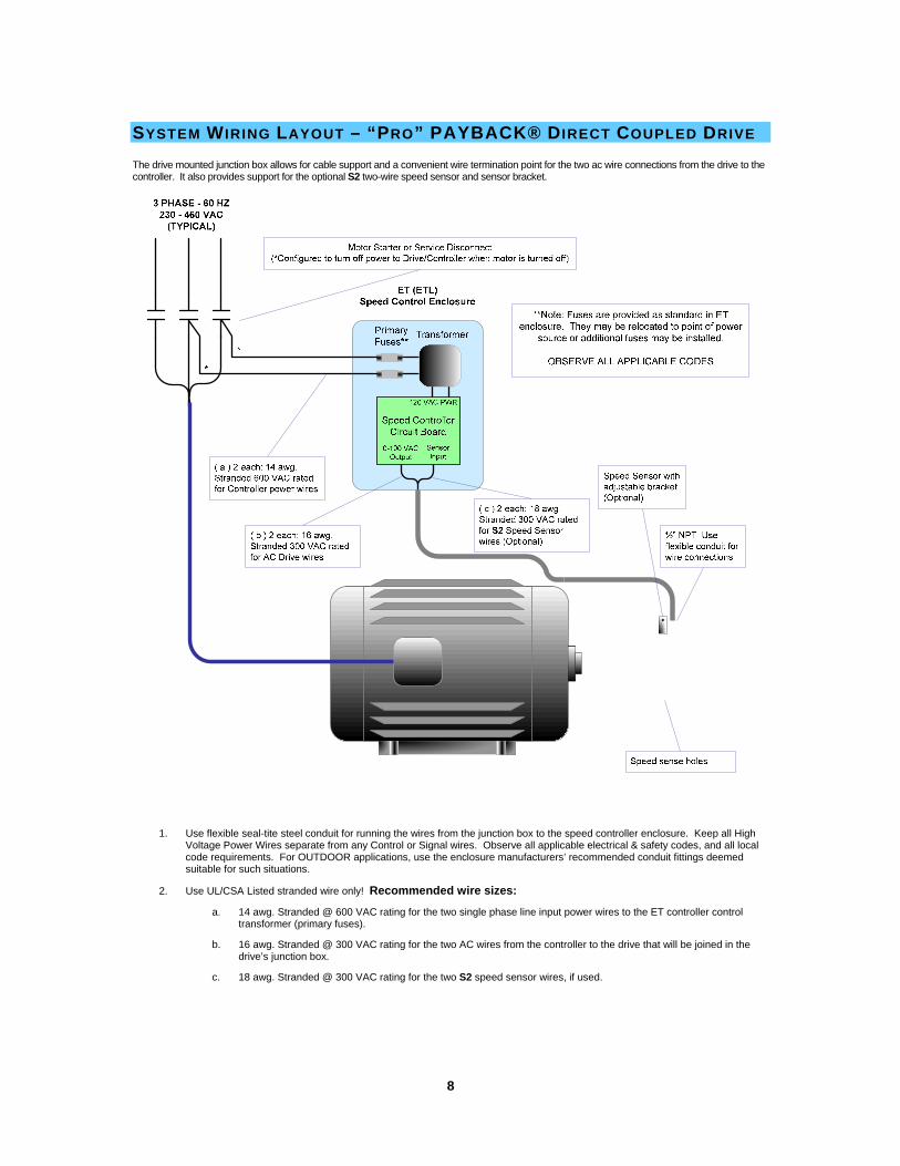
SYSTEM WIRING LAYOUT – “PRO” PAYBACK® DIRECT COUPLED DRIVE The drive mounted junction box allows for cable support and a convenient wire termination point for the two ac wire connections from the drive to the controller. It also provides support for the optional S2 two-wire speed sensor and sensor bracket.
1. Use flexible seal-tite steel conduit for running the wires from the junction box to the speed controller enclosure. Keep all High Voltage Power Wires separate from any Control or Signal wires. Observe all applicable electrical & safety codes, and all local code requirements. For OUTDOOR applications, use the enclosure manufacturers’ recommended conduit fittings deemed suitable for such situations.
2. Use UL/CSA Listed stranded wire only! Recommended wire sizes:
a. 14 awg. Stranded @ 600 VAC rating for the two single phase line input power wires to the ET controller control transformer (primary fuses).
b. 16 awg. Stranded @ 300 VAC rating for the two AC wires from the controller to the drive that will be joined in the drive’s junction box.
c. 18 awg. Stranded @ 300 VAC rating for the two S2 speed sensor wires, if used.
9
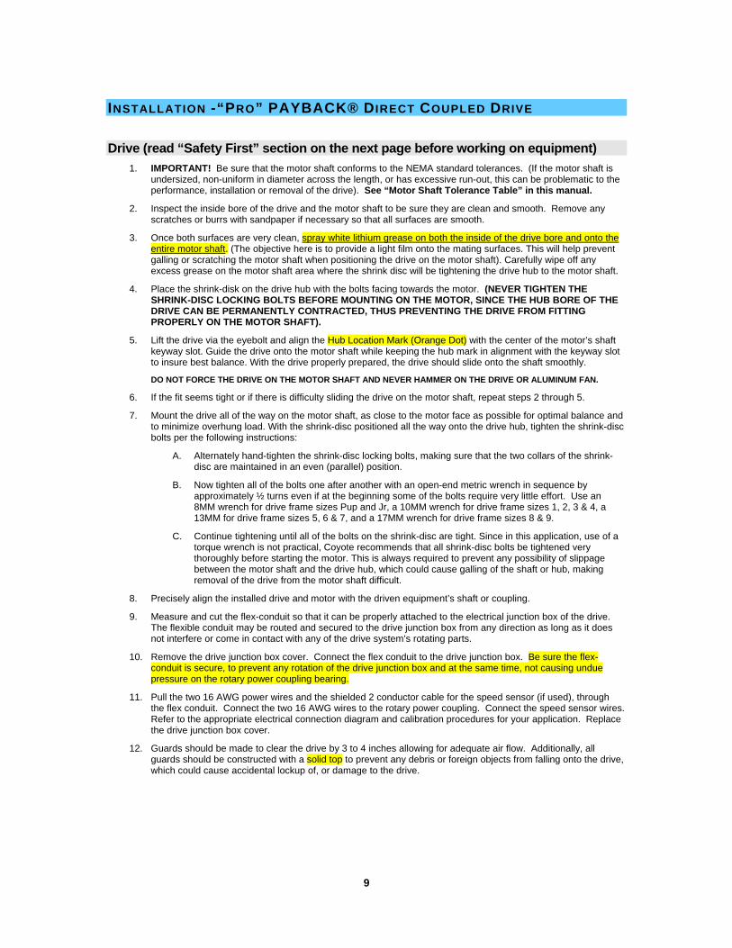
INSTALLATION -“PRO” PAYBACK® DIRECT COUPLED DRIVE
Drive (read “Safety First” section on the next page before working on equipment) 1. IMPORTANT! Be sure that the motor shaft conforms to the NEMA standard tolerances. (If the motor shaft is
undersized, non-uniform in diameter across the length, or has excessive run-out, this can be problematic to the performance, installation or removal of the drive). See “Motor Shaft Tolerance Table” in this manual.
2. Inspect the inside bore of the drive and the motor shaft to be sure they are clean and smooth. Remove any scratches or burrs with sandpaper if necessary so that all surfaces are smooth.
3. Once both surfaces are very clean, spray white lithium grease on both the inside of the drive bore and onto the entire motor shaft. (The objective here is to provide a light film onto the mating surfaces. This will help prevent galling or scratching the motor shaft when positioning the drive on the motor shaft). Carefully wipe off any excess grease on the motor shaft area where the shrink disc will be tightening the drive hub to the motor shaft.
4. Place the shrink-disk on the drive hub with the bolts facing towards the motor. (NEVER TIGHTEN THE SHRINK-DISC LOCKING BOLTS BEFORE MOUNTING ON THE MOTOR, SINCE THE HUB BORE OF THE DRIVE CAN BE PERMANENTLY CONTRACTED, THUS PREVENTING THE DRIVE FROM FITTING PROPERLY ON THE MOTOR SHAFT).
5. Lift the drive via the eyebolt and align the Hub Location Mark (Orange Dot) with the center of the motor’s shaft keyway slot. Guide the drive onto the motor shaft while keeping the hub mark in alignment with the keyway slot to insure best balance. With the drive properly prepared, the drive should slide onto the shaft smoothly.
DO NOT FORCE THE DRIVE ON THE MOTOR SHAFT AND NEVER HAMMER ON THE DRIVE OR ALUMINUM FAN.
6. If the fit seems tight or if there is difficulty sliding the drive on the motor shaft, repeat steps 2 through 5.
7. Mount the drive all of the way on the motor shaft, as close to the motor face as possible for optimal balance and to minimize overhung load. With the shrink-disc positioned all the way onto the drive hub, tighten the shrink-disc bolts per the following instructions:
A. Alternately hand-tighten the shrink-disc locking bolts, making sure that the two collars of the shrink-disc are maintained in an even (parallel) position.
B. Now tighten all of the bolts one after another with an open-end metric wrench in sequence by approximately ½ turns even if at the beginning some of the bolts require very little effort. Use an 8MM wrench for drive frame sizes Pup and Jr, a 10MM wrench for drive frame sizes 1, 2, 3 & 4, a 13MM for drive frame sizes 5, 6 & 7, and a 17MM wrench for drive frame sizes 8 & 9.
C. Continue tightening until all of the bolts on the shrink-disc are tight. Since in this application, use of a torque wrench is not practical, Coyote recommends that all shrink-disc bolts be tightened very thoroughly before starting the motor. This is always required to prevent any possibility of slippage between the motor shaft and the drive hub, which could cause galling of the shaft or hub, making removal of the drive from the motor shaft difficult.
8. Precisely align the installed drive and motor with the driven equipment’s shaft or coupling.
9. Measure and cut the flex-conduit so that it can be properly attached to the electrical junction box of the drive. The flexible conduit may be routed and secured to the drive junction box from any direction as long as it does not interfere or come in contact with any of the drive system’s rotating parts.
10. Remove the drive junction box cover. Connect the flex conduit to the drive junction box. Be sure the flex-conduit is secure, to prevent any rotation of the drive junction box and at the same time, not causing undue pressure on the rotary power coupling bearing.
11. Pull the two 16 AWG power wires and the shielded 2 conductor cable for the speed sensor (if used), through the flex conduit. Connect the two 16 AWG wires to the rotary power coupling. Connect the speed sensor wires. Refer to the appropriate electrical connection diagram and calibration procedures for your application. Replace the drive junction box cover.
12. Guards should be made to clear the drive by 3 to 4 inches allowing for adequate air flow. Additionally, all guards should be constructed with a solid top to prevent any debris or foreign objects from falling onto the drive, which could cause accidental lockup of, or damage to the drive.

10
SAFETY FIRST
WHEN SERVICING, INSTALLING, OR REMOVING THE DRIVE:
• ALL SERVICE SHOULD BE PERFORMED BY QUALIFIED PERSONNEL.
• ALWAYS TURN OFF (LOCKOUT/TAG-OUT) ALL POWER TO THE MOTOR AND CONTROLS.
• BE AWARE OF THE DRIVE’S WEIGHT AND USE PROPER LIFTING EQUIPMENT AND PROCEDURES TO AVOID INJURY. (REFER TO THE SECTION TITLED “TECHNICAL DATA – PRO PAYBACK® DIRECT COUPLED DRIVES” IN THIS MANUAL TO DETERMINE THE WEIGHT OF THE SPECIFIC DRIVE MODEL).
• OBSERVE ALL SAFETY PRECAUTIONS FOR THIS VARIABLE SPEED DRIVE AS YOU WOULD FOR ALL MOTORS AND OTHER ROTATING EQUIPMENT.
11
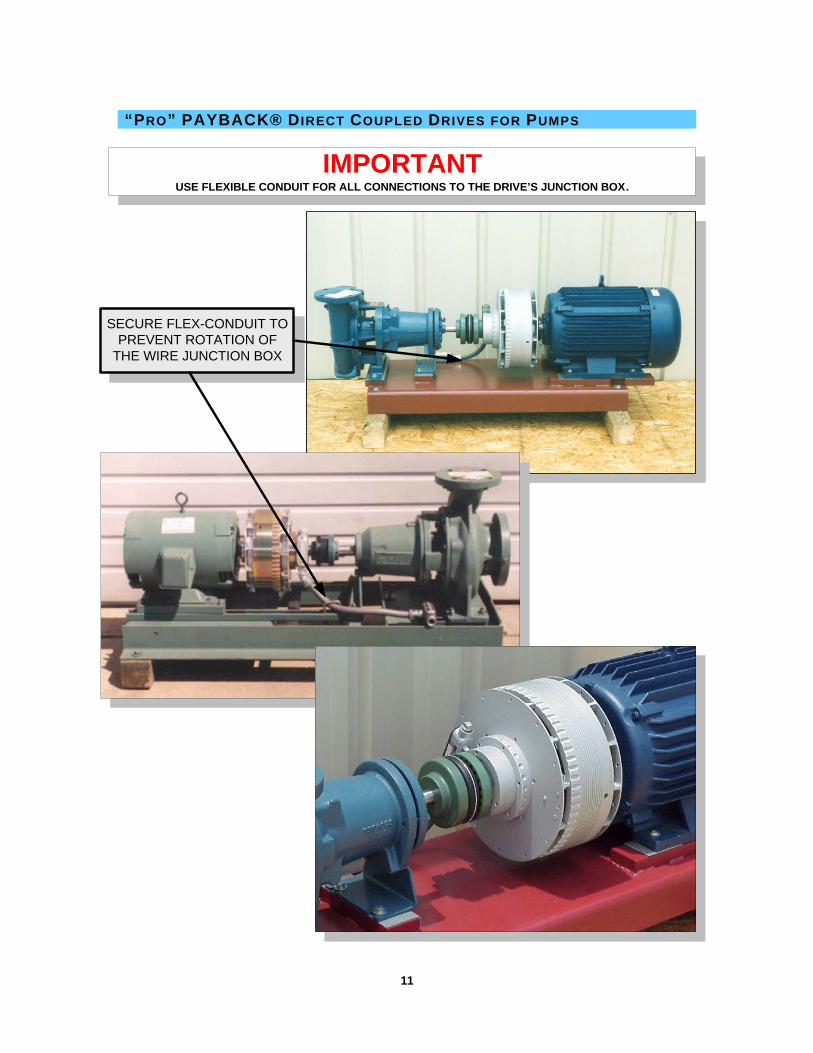
“PRO” PAYBACK® DIRECT COUPLED DRIVES FOR PUMPS
SECURE FLEX-CONDUIT TOPREVENT ROTATION OF
THE WIRE JUNCTION BOX
IMPORTANTUSE FLEXIBLE CONDUIT FOR ALL CONNECTIONS TO THE DRIVE’S JUNCTION BOX.

12
A
BC
TECHNICAL DATA – “PRO” PAYBACK® DIRECT COUPLED DRIVES
AC Motor Data (4 Pole, 60 Hz, 1750 RPM)
Pro-PAYBACK® Direct-Coupled and BRUSHLESS
Shaft-Mounted Variable Speed Drive. PAYBACK® RELIABILITY…”PURE & SIMPLE” ™
MOTOR HP
MOTOR FRAME
ODP (TEFC)
MOTOR SHAFT
DIAMETER
PAYBACK® Drive Model
Output Speed Range (RPM)
Output Shaft Diameter
(Standard Sizes)
3 182T 0-1700
5 184T 1.125 PRO-1
0-1600 1.125
7.5 213T 0-1700
10 215T 1.375 PRO-2
0-1600 1.375
15 254T 0-1700
20 256T 1.625 PRO-3
0-1600 1.625
25 284T 0-1700
30 286T 1.875 PRO-4
0-1650 1.875
40 324T 0-1700
50 326T 2.125 PRO-5
0-1650 2.125
60 364T 0-1700
75 365T 2.375 PRO-6
0-1650 2.375
100 404T (405T) 0-1700
125 405T (444T**)
2.875 (**3.375) PRO-7
0-1650
2.875 (**3.375)
444T 150
(445T) 3.375 PRO-8 0-1650 3.375
445T 200
(447T) 3.375 PRO-9 0-1650 3.375
DATA SUBJECT TO CHANGE WITHOUT NOTICE.
Model Size A B C** (Standard)
Weight (lbs.)
Pro-1 9.00 7.50 1.75 52
Pro-2 10.50 8.00 2.00 74
Pro-3 12.30 9.00 2.25 118
Pro-4 14.00 10.00 2.50 181
Pro-5 16.30 11.00 2.75 299
Pro-6 17.30 12.00 3.00 360
Pro-7 21.00 13.00 3.00 589
Pro-8 24.00 14.00 3.50 750
Pro-9 26.00 15.00 3.50 989 ** For non-standard shaft lengths, consult factory.
13
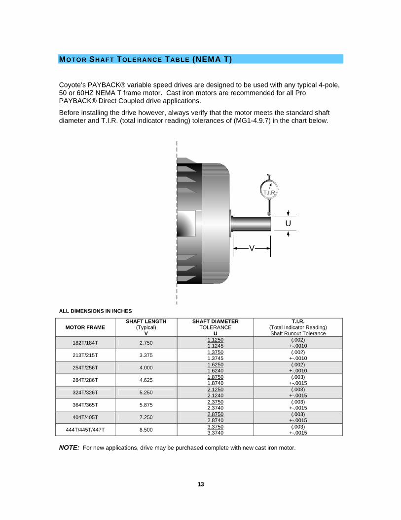
MOTOR SHAFT TOLERANCE TABLE (NEMA T)
Coyote’s PAYBACK® variable speed drives are designed to be used with any typical 4-pole, 50 or 60HZ NEMA T frame motor. Cast iron motors are recommended for all Pro PAYBACK® Direct Coupled drive applications.
Before installing the drive however, always verify that the motor meets the standard shaft diameter and T.I.R. (total indicator reading) tolerances of (MG1-4.9.7) in the chart below.
ALL DIMENSIONS IN INCHES
MOTOR FRAME SHAFT LENGTH
(Typical) V
SHAFT DIAMETER TOLERANCE
U
T.I.R. (Total Indicator Reading) Shaft Runout Tolerance
182T/184T 2.750 1.1250 1.1245
(.002) +-.0010
213T/215T 3.375 1.3750 1.3745
(.002) +-.0010
254T/256T 4.000 1.6250 1.6240
(.002) +-.0010
284T/286T 4.625 1.8750 1.8740
(.003) +-.0015
324T/326T 5.250 2.1250 2.1240
(.003) +-.0015
364T/365T 5.875 2.3750 2.3740
(.003) +-.0015
404T/405T 7.250 2.8750 2.8740
(.003) +-.0015
444T/445T/447T 8.500 3.3750 3.3740
(.003) +-.0015
NOTE: For new applications, drive may be purchased complete with new cast iron motor.
U
V
T.I.R

14
ORDERING INFORMATION – “PRO” PAYBACK® DIRECT COUPLED DRIVES
IMPORTANT: Always verify motor frame and shaft sizes.
Pro PAYBACK® Drive Selection (based on motor speed of 1750 rpm) To select the correct size drive, simply locate the horsepower and frame size of you’re AC motor in the “Technical Data” chart on the previous page.
EXAMPLE: A 50 HP motor with a 326T frame would require a Pro-5 PAYBACK® Drive.
If your particular requirements are not listed, please contact the factory.

15
SPEED SENSOR ORIENTATION & INSTALLATION – “PRO” PAYBACK®
To be installed by trained, qualified service personnel only. Always observe all safety precautions regarding rotating machinery and all applicable electrical codes.
SPEEDSENSOR
LED MotionIndicator
GAP Dimension (Rotary Transformer surface to Sensor FACE)Typical: 1/16" - 3/32"
White (+15VDC)
Black (Signal)
PAYBACK® Rotary Transformer
Speed Sensor Holes
Adjustment Slot
1: The Coyote 2-wire Speed Sensor MUST BE ORIENTED as shown above with respect to the direction of travel of the rotating speed sensor holes to be detected on the rotary transformer.
Mounting the sensor in any plane other than as shown above will cause erratic operation.
2: Always adjust the gap between the surface and sensor face to the maximum safe operating distance, typically 1/16 – 3/32 inch.
Note: Setting the gap too close may damage the sensor.

16
MANUAL LOCKUP INSTRUCTIONS
For Emergency Full-Speed By-Pass
WARNING BEFORE BEGINNING THE MANUAL LOCKUP PROCEDURE, ALWAYS REMOVE POWER FROM BOTH THE CONTROL AND MOTOR WHEN INSTALLING OR REMOVING LOCKUP BOLTS, AND/OR WHEN SERVICING THE DRIVE. ALWAYS LOCK OUT THE POWER TO THE MOTOR TO PREVENT ACCIDENTAL STARTUP WHILE PERFORMING THIS PROCEDURE.
1. Select the appropriate size lockup bolt for your drive from the chart below.
DRIVE MODEL SIZE (QTY EA) LOCKUP BOLT SIZE
SIZE 1, 2, 3 (2 EA) 3/8 x 3/4L x 16TPI
SIZE 4, 5, 6 (2 EA) 1/2 x 1L x 13TPI
SIZE 7, 8, 9 (4 EA) 3/4 x 1-1/2L x 10TPI
2. Locate the threaded lockup holes on opposite sides of the drum’s circumference.
LOCKUPHOLE
LOCKUPHOLE
LOCKUPBOLT
LOCKUPBOLT
DRUM
3. Screw the lockup bolts into the holes and ALTERNATELY HAND TIGHTEN until they each make contact with the finger peaks of the inner portion of the drive as shown below.
IMPORTANT: If your drive incorporates the speed sensor option, be sure that the lockup bolts do not interfere or come in contact with the speed sensor. The speed sensor can be temporarily pivoted out of the way and securely repositioned on the support arm to assure adequate clearance from the rotating lockup bolts. After the lockup bolts are removed, the speed sensor gap can be properly re-adjusted. Follow the “Speed Sensor Orientation and Installation” instructions in this manual.
CORRECTALIGNMENT
INCORRECTALIGNMENT
4. NOW TIGHTEN LOCKUP BOLTS SECURELY with a wrench, and then you may restore power to the motor. The drive will now run at motor speed.

17

18
START UP PROCEDURE - “PRO” PAYBACK® DIRECT COUPLED DRIVE
“Pro-PAYBACK®” Magnetic Coupled Variable Speed Drives with “ET” series Speed Controls
Before starting, check and make sure the two emergency bypass lock-up bolts located on the outside diameter of the drive’s drum have been removed from the drive. See manual lockup instructions.
The controls may or may not be installed on the equipment when it arrives at the job site. Please read the following instructions and verify that all of the following steps are completed for the initial field set up.
“ET” Control Enclosure Installation: Mount the “ET” PAYBACK® control enclosure in close proximity to the motor starter or motor service disconnect (whichever is the final device feeding power to the motor). Optionally, at customer preference, the controller can also be remotely mounted a distance away from the equipment. The controller typically is to be connected to two of the high voltage power wires going to the motor to insure that when the motor is switched off, all power to the controller and drive is also turned off. (The purpose for the transformer in the “ET” controller enclosure is to conveniently provide isolated, 115 VAC single phase power to the controller circuitry when the motor is running.)
The panel with associated components may be easily removed from the enclosure by removing the four panel mounting screws and unplugging TB1 and TB2 plug terminals from the speed controller circuit board. This will allow you to drill the necessary holes for the wires to be connected from the power source, drive and control signal without damage to the controller components. (See appropriate controller connection diagram for terminal connections.) Be sure to comply with all local electrical codes and observe safe wiring practices.
The minimum wire requirements are as follows:
The two high voltage power wires that will connect to the line input fuse block assembly in the control enclosure should be at least 14 gauge/stranded/600 volt insulation rating. See also: PAYBACK® Drive System Wiring Layout Diagram and all relevant electrical drawings.
Attention Electrician/Installer, Before Applying Power: 1. Turn OFF ALL POWER to the “ET” enclosure.
2. Turn the “Man-Off-Auto” switch on the front enclosure cover to the “OFF” position.
3. Open the “ET” control enclosure and check the control transformer primary jumpers in the “ET” enclosure to verify that they are correct for your specific line voltage. Re-jumper correctly, if required.
4. UN-PLUG the TB1 power plug to the speed controller circuit board.
5. Turn the motor on briefly to verify correct rotation of the motor. Correct motor phase wiring if necessary.
6. Using an AC voltmeter, check across the unplugged TB1 plug, terminals 1 and 8 to verify that there is 115 VAC when the POWER IS TURNED ON to the control transformer. (The Speed controller circuit voltage input power requirement is 115 VAC +/- 10% typ.)
7. If you DO NOT read 115 VAC across terminals 1 and 8 of the TB1 plug, then repeat steps 1 – 6. If you DO read 115 VAC across terminals 1 and 8 of the TB1 Plug, turn power OFF and then re-install plug TB1 to the controller board.
The PAYBACK® drive system is now ready for manual operation. The system is now ready for check out under remote control conditions. Refer to relevant calibration procedures and complete the WARRANTY registration form.

19
SIGNAL FOLLOWING MODE SETUP PROCEDURE – “PRO” PAYBACK®
The following adjustments apply to AC1/AC2 SIGNAL FOLLOWING applications only!
For Stand-Alone PRESSURE SET POINT adjustment procedure: See “AC1/AC2 Pressure Set Point Mode Setup Procedure”.
Your AC1/AC2 controller has been pre-calibrated for your convenience and some of the settings may be factory sealed to prevent accidental adjustments in the field. Some minor adjustments may be necessary to accommodate your particular application. VERY IMPORTANT! We recommend that you monitor the motor current with a clamp-on amp meter while making these adjustments.
IN ALL CORRECTLY SIZED APPLICATIONS, YOU SHOULD ALWAYS BE ABLE TO OPERATE THROUGHOUT THE ENTIRE SPEED RANGE WITHOUT EXCEEDING THE MAXIMUM FULL LOAD AMPS OF THE MOTOR. THIS ALSO APPLIES WHEN IN FULL SPEED LOCKUP MODE.
Note that the circuit board potentiometers are the 20-turn type allowing for precise control settings.
I. MANUAL MODE ADJUSTMENTS (Be sure to monitor motor current as described above)
1. Turn the 3-way selector switch to the MANUAL position.
2. Set the operator speed control knob full counterclockwise (minimum on dial).
3. Adjust the MIN pot on the AC1/AC2 circuit board for desired minimum speed.
(USUALLY FACTORY PRESET FOR ZERO OUTPUT, with LED indicator ON.)
4. Now slowly turn the operator speed control knob up to full clockwise (maximum on dial).
5. Adjust the MAX pot on the AC1/AC2 circuit board for maximum desired speed. OBSERVE actual RPM reading on the meter, if supplied.
To avoid dead band at the top end of the speed range DO NOT OVER-ADJUST THIS SETTING.
Note: The LCD speed meter has been factory pre-calibrated. When a speed meter is not supplied, we recommend using a hand held optical tachometer to monitor the output speed of the drive.
The drive may now be manually operated throughout the entire speed range with the actual speed indicated by the speed meter.
6. It may be necessary to repeat steps 2 through 5 to fine-tune the final adjustments.
7. For smooth acceleration (Soft-Start) during initial startup, turn the ACCEL pot clockwise to lengthen the ramp of acceleration.
Note: The DECEL pot has been factory set for minimum (full counter clockwise).
II. AUTO MODE ADJUSTMENTS (Be sure to monitor motor current as described above)
1. Turn the 3-way selector switch to the AUTO position.
2. With the external input signal at minimum, i.e.: 4ma for 4-20ma input, adjust for desired minimum speed with the ZERO pot on the AC1/AC2 circuit board.
3. With the external input signal at maximum, i.e.: 20ma for 4-20ma input, adjust for desired maximum speed with the SPAN pot on the AC1/AC2 circuit board.
To avoid dead band at the top end of the speed range DO NOT OVER-ADJUST THIS SETTING.
Check to make sure minimum adjustment is still correct. Fine tune until desired span is reached.
IF FOR ANY REASON, YOUR DRIVE FAILS TO OPERATE PROPERLY AFTER YOU HAVE PERFORMED THE ABOVE PROCEDURES, PLEASE CALL THE FACTORY FOR FURTHER INSTRUCTIONS AT 817.485.3336.

20
PRESSURE SET POINT MODE SETUP PROCEDURE – “PRO” PAYBACK®
The following adjustments apply to AC1/AC2 PRESSURE SET POINT applications only!
For SIGNAL FOLLOWING adjustment procedure: See “AC1/AC2 Signal Following Mode Setup Procedure”.
Your AC1/AC2 controller has been pre-calibrated for your convenience and some of the settings may be factory sealed to prevent accidental adjustments in the field. Some minor adjustments may be necessary to accommodate your particular application. VERY IMPORTANT! We recommend that you monitor the motor current with a clamp-on amp meter while making these adjustments.
IN ALL CORRECTLY SIZED APPLICATIONS, YOU SHOULD ALWAYS BE ABLE TO OPERATE THROUGHOUT THE ENTIRE SPEED RANGE WITHOUT EXCEEDING THE MAXIMUM FULL LOAD AMPS OF THE MOTOR. THIS ALSO APPLIES WHEN IN FULL SPEED LOCKUP MODE.
Note that the circuit board potentiometers are the 20-turn type allowing for precise control settings.
I. MANUAL MODE ADJUSTMENTS (Be sure to monitor motor current as described above)
1. Turn the 3-way selector switch to the MANUAL position.
2. Set the operator speed control knob full counterclockwise (minimum on dial).
3. Adjust the MIN pot on the AC1/AC2 circuit board for desired minimum speed.
(USUALLY FACTORY PRESET FOR ZERO OUTPUT, with LED indicator ON.)
4. Now slowly turn the operator speed control knob up to full clockwise (maximum on dial).
5. Adjust the MAX pot on the AC1/AC2 circuit board for maximum desired speed. OBSERVE actual RPM reading on the meter, if supplied.
To avoid dead band at the top end of the speed range DO NOT OVER-ADJUST THIS SETTING.
Note: The LCD speed meter has been factory pre-calibrated. When a speed meter is not supplied, we recommend using a hand held optical tachometer to monitor the output speed of the drive.
The drive may now be manually operated throughout the entire speed range with the actual speed indicated by the speed meter.
6. It may be necessary to repeat steps 2 through 5 to fine-tune the final adjustments.
7. For smooth acceleration (Soft-Start) during initial startup, turn the ACCEL pot clockwise to lengthen the ramp of acceleration.
Note: The DECEL pot has been factory set for minimum (full counter clockwise).
II. AUTO MODE ADJUSTMENTS (Be sure to monitor motor current as described above)
PRESSURE SENSOR SIGNAL USED AS A SET POINT SPEED CONTROL
1. Turn the 3-way selector switch to the AUTO position.
2. Adjust for the desired pressure set point via the ZERO pot, located on the AC1/AC2 board.
Note that the SPAN potentiometer which is also located on the AC1/AC2 circuit board is factory set, typically 4 to 5 turns from maximum clockwise allowing for higher gain conditioning of the pressure transmitter input signal for proper set point mode operation.
III. 2WP PRESSURE SENSOR/TRANSMITTER
*Your 2WP Pressure Sensor/Transmitter has been factory calibrated to specifications determined at the time the drive system was ordered. NO FIELD ADJUSTMENTS ARE REQUIRED.
IF FOR ANY REASON, YOUR DRIVE FAILS TO OPERATE PROPERLY AFTER YOU HAVE PERFORMED THE ABOVE PROCEDURES, PLEASE CALL THE FACTORY FOR FURTHER INSTRUCTIONS AT 817.485.3336.

21
WARRANTY REGISTRATION FORM – “PRO” PAYBACK®
FOR FACTORY WARRANTY TO BE VALID, INSTALLER MUST COMPLETE THIS FORM.
Please make copies of this blank form. Fill out the required data for each system. FAX COMPLETED FORM to Coyote Electronics, Inc. 817-427-4395 or 817-485-9437
INSTALLATION DATE PERFORMED BY
PHONE FAX
JOB/SITE NAME
ADDRESS
APPLICATION / TYPE OF EQUIPMENT (Be specific)
EQUIPMENT DESIGNATION, UNIT #, I.D. #
PAYBACK DRIVE MODEL # DRIVE SERIAL #
MOTOR NAMEPLATE DATA
HP/KW RPM FRAME #
ODP TEFC OTHER
50HZ 60HZ 1-PHASE 3-PHASE
FULL LOAD AMPS @ AC VOLTS
RECORD ALL DATA WITH SYSTEM OPERATING AT MAXIMUM (100% FULL LOAD / RPM CONDITION)
VERIFY THAT THE CONTROLLER VOLTAGE TO THE DRIVE IS SET TO MAXIMUM (APPROXIMATELY 100VAC)
ACTUAL MEASURED DATA @ FULL LOAD RPM
LINE AC VOLTS MOTOR AC AMPS
MOTOR RPM DRIVE OUTPUT/LOAD RPM
@ CONTROLLER AC VOLTAGE OUTPUT TO PAYBACK DRIVE COIL VAC
WARNING: The installation and use of Coyote Electronics, Inc.’s products should be in accordance with the provisions of the U.S. National Electrical Code and/or other local codes or industry standards that are pertinent to the particular end use.
Installation or use not in accordance with these codes and standards could be hazardous to personnel and/or equipment.
Coyote Electronics, Inc. 4701 Old Denton Road Fort Worth, TX. 76117 Phone: 817-485-3336
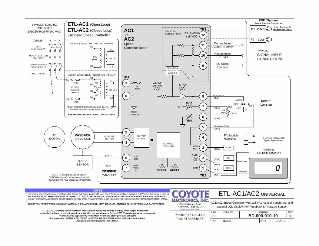
ETL-AC1/AC2 SCHEMATIC – PRO PAYBACK®
H4
H3
H2
H1
L2
L1
2FU
1FU
X1
X2
5A250V
ISO SignalCommon
Voltage Input +0-10VDC
Current Input0-20mA, 4-20mA
(+)
(-)
HIGH
LOW
SPEEDSENSOR
3 PHASE, 50/60 HZLINE INPUT
208/230/460/575/600 VAC
TYPICAL
MAINDISCONNECT
MOTOR STARTERCONTACTS
MOTOR SERVICEDISCONNECTS
(BY OTHERS)
ACMOTOR
6
7
PAYBACKDRIVE COIL
ETL-AC1 (Open Loop)
ETL-AC2 (Closed Loop)Enclosed Speed Controller
*Each DC1/DC2 Controller requires its ownindividual isolation control transformer.
0-100 VACOUTPUT
COYOTE “S2” Digital Speed SensorOPTIONAL with AC1 Open Loop Controller
REQUIRED with AC2 Closed Loop Controller
12
4OUTPUTSTAGE
CONTROLCIRCUITRY
2WP *Optional2-Wire Pressure Transducer
Apply Pressure toHIGH PORT ONLY
TYPICALSIGNAL INPUTCONNECTIONS
MAX
MIN
SPANZERO
(Set Point)
-5V
ISOLATION
BARRIER
9
10
11
ISOLATEDCONNECTIONS
AC1-OR-
AC2SpeedController Board
TB1
TB2
3
2
+15VOUT
RATEFREQ.
IN DECEL ACCEL
+15VOUT
RATEFREQ.OUT
COM
10KPOT
6
7 CW
8
5
Auto Output
Reference Input
(ORN)
(WHT)
(BLU)
(BLK)
(GRN)
AUTO
MAN
OFF
(1)
(2)
(3)
MODESWITCH
+15V
SIG
COM
3
(BLK)
(WHT)
(RED)
2
1(RED)
(BLK)
*OptionalLCD RPM DISPLAY
F/V Module*Optional
+
-0-10 VDC (ISOLATED)Speed Signal Output
MICRON B250BTZ13JK - 230/460 VAC PRIMARY
ETL-AC1/AC2 UNIVERSAL
AC1/AC2 Speed Controller with 115 VAC control transformer andoptional LCD display, F/V Feedback & Pressure Sensor
SIZE FSCM NO DWG NO REV
A BD-000-010-10 BSCALE NONE SHEET 1 OF 1
4701 Old Denton RoadFort Worth, Texas 76117
www.payback.com
*The control power transformer is configured to assure that single phase 115 VAC power to the controller is available ONLY when the motor is running. EACH AC1 or AC2 CONTROLLER MUST BE CONNECTED TO ITS OWN INDIVIDUAL POWER ISOLATION TRANSFORMER FOR PROPER OPERATION.
DO NOT CONNECT ADDITIONAL CONTROLLERS TO THE SAME TRANSFORMER. KEEP ALL HIGH VOLTAGE WIRES SEPARATE FROM OTHER WIRES.** DO NOT RUN POWER WIRES AND SIGNAL WIRES IN THE SAME CONDUIT...KEEP SEPARATE. OBSERVE ALL ELECTRICAL AND SAFETY CODES.
NOTES
AC1/AC2 variable speed controller with isolated input conditioning circuitry that accepts and followsa standard voltage or current signal, or optionally, the signal from a Coyote 2WP (Two-wire pressure transducer)
for stand alone applications to maintain a constant static pressure set point.See applicable: SIGNAL FOLLOWING or PRESSURE SET POINT MODE calibration instructions
Designed and manufactured in the U.S.A.
FUSESClass CCTYPICAL
115 VAC
(WHT)
(BLK)
OBSERVEPOLARITY
Rate Input
Common
TB3
0
8
1
Phone: 817.485.3336Fax: 817.485.9437
AC/DCCOMMON
ISO Output+15 VDC
230
230
H2
H1
X1
X2
MICRON B250WZ13XK - 575 VAC PRIMARY
115 VAC575
(600)
SEE TRANSFORMER CONNECTION DIAGRAM

3
21
4
ITEMNO. PART NUMBER DESCRIPTION QTY.
1 PPB(*) EM-DRUM SA EM-DRUM SUB-ASSEMBLY, PRO 12 RPCU-RT(*) ROTARY POWER COUPLING 13 PPB(*) RPCU SCREWS ROTARY POWER COUPLING SCREWS 64 PPB(*) SHRINKDISC SHRINK DISC ASSEMBLY 1
ITEMNO. PART NUMBER DESCRIPTION QTY.
1 PPB(*) EM-DRUM SA EM-DRUM SUB-ASSEMBLY, PRO 12 RPCU-RT(*) ROTARY POWER COUPLING 13 PPB(*) RPCU SCREWS ROTARY POWER COUPLING SCREWS 64 PPB(*) SHRINKDISC SHRINK DISC ASSEMBLY 1 D
C
B
AA
B
C
D
12345678
8 7 6 5 4 3 2 1
THE INFORMATION CONTAINED IN THISDRAWING IS THE SOLE PROPERTY OFCOYOTE ELECTRONICS, INC. ANY REPRODUCTION IN PART OR AS A WHOLEWITHOUT THE WRITTEN PERMISSION OFCOYOTE ELECTRONICS, INC. IS PROHIBITED.
PROPRIETARY AND CONFIDENTIAL
NEXT ASSY USED ON
APPLICATION
DIMENSIONS ARE IN INCHESTOLERANCES:FRACTIONALANGULAR: MACH BEND TWO PLACE DECIMAL THREE PLACE DECIMAL
INTERPRET GEOMETRICTOLERANCING PER:
MATERIAL
FINISH
SEE BOM
N/A
DRAWN
CHECKED
ENG APPR.
MFG APPR.
Q.A.
COMMENTS:
DATENAME
TITLE:
SIZE
BDWG. NO. REV
WEIGHT: SCALE:N/A
UNLESS OTHERWISE SPECIFIED:
HBROOKS 03/27/06
PRO DRIVE AD, PRO
SHEET 1 OF 1
AD-000-032-80-ILDO NOT SCALE DRAWING
COYOTEELECTRONICS, INC.
4701 Old Denton RoadFort Worth, Texas 76117
Phone: 817.485.3336Fax: 817.485.9437
8
76
4
32
1
5
98
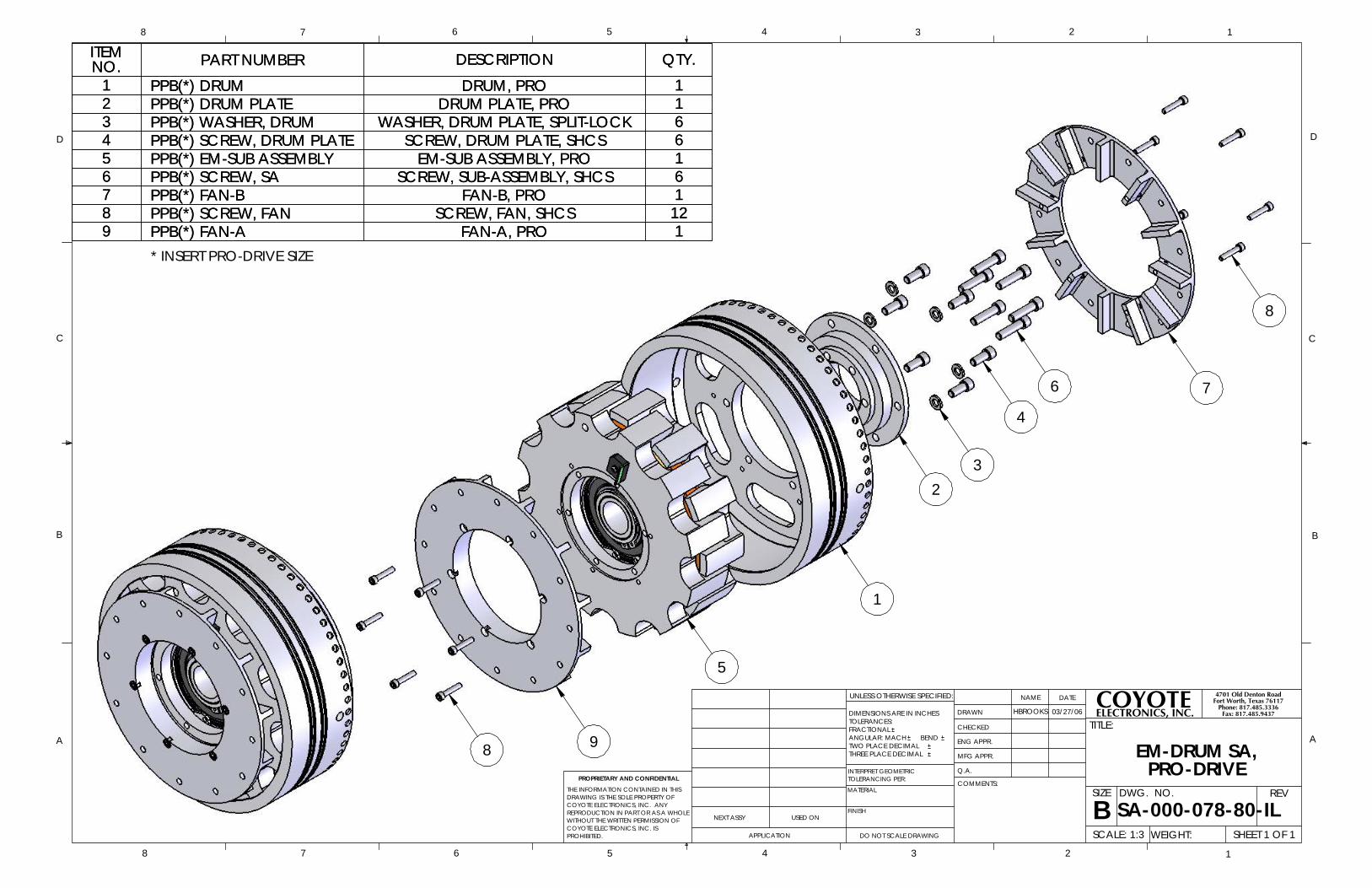
* INSERT PRO-DRIVE SIZE
ITEMNO. PART NUMBER DESCRIPTION QTY.
1 PPB(*) DRUM DRUM, PRO 12 PPB(*) DRUM PLATE DRUM PLATE, PRO 13 PPB(*) WASHER, DRUM WASHER, DRUM PLATE, SPLIT-LOCK 64 PPB(*) SCREW, DRUM PLATE SCREW, DRUM PLATE, SHCS 65 PPB(*) EM-SUB ASSEMBLY EM-SUB ASSEMBLY, PRO 16 PPB(*) SCREW, SA SCREW, SUB-ASSEMBLY, SHCS 67 PPB(*) FAN-B FAN-B, PRO 18 PPB(*) SCREW, FAN SCREW, FAN, SHCS 129 PPB(*) FAN-A FAN-A, PRO 1
D
C
B
AA
B
C
D
12345678
8 7 6 5 4 3 2 1
THE INFORMATION CONTAINED IN THISDRAWING IS THE SOLE PROPERTY OFCOYOTE ELECTRONICS, INC. ANY REPRODUCTION IN PART OR AS A WHOLEWITHOUT THE WRITTEN PERMISSION OFCOYOTE ELECTRONICS, INC. IS PROHIBITED.
PROPRIETARY AND CONFIDENTIAL
NEXT ASSY USED ON
APPLICATION
DIMENSIONS ARE IN INCHESTOLERANCES:FRACTIONALANGULAR: MACH BEND TWO PLACE DECIMAL THREE PLACE DECIMAL
INTERPRET GEOMETRICTOLERANCING PER:
MATERIAL
FINISH
DRAWN
CHECKED
ENG APPR.
MFG APPR.
Q.A.
COMMENTS:
DATENAME
TITLE:
SIZE
BDWG. NO. REV
WEIGHT: SCALE: 1:3
UNLESS OTHERWISE SPECIFIED:
HBROOKS 03/27/06
EM-DRUM SA,PRO-DRIVE
SHEET 1 OF 1
SA-000-078-80-ILDO NOT SCALE DRAWING
COYOTEELECTRONICS, INC.
4701 Old Denton RoadFort Worth, Texas 76117
Phone: 817.485.3336Fax: 817.485.9437

9 6
32
15
4
7
8
10
11
12
ITEMNO. PART NUMBER DESCRIPTION QTY.
1 PPB(*) HUB (SPECIFY BORE SIZE) MAIN SUPPORT HUB 12 PPB(*) BEARING MAIN DRIVE BEARING 13 PPB(*) EXT SNAP-RING EXT SNAP-RING - MAIN DRIVE BEARING 14 PPB(*) SPIDER-B SPIDER-B - INPUT SIDE 15 PPB(*) COIL DRIVE COIL 16 PPB(*) SPIDER-A SPIDER-A - OUTPUT SIDE 17 PPB(*) WASHER WASHER, PRO DRIVE, SPLIT-LOCK 68 PPB(*) SCREW-SPIDERS SCREW-SPIDERS, PRO-DRIVE 69 PPB(*) INT SNAP-RING INT SNAP-RING - MAIN DRIVE BEARING 1
10 PPB(*) BRIDGE RECTIFIER, BRIDGE, PRO-DRIVE 111 PPB(*) WASHER-BRIDGE WASHER, RECTIFIER 112 PPB(*) SCREW-BRIDGE SCREW, RECTIFIER 1
D
C
B
AA
B
C
D
12345678
8 7 6 5 4 3 2 1
THE INFORMATION CONTAINED IN THISDRAWING IS THE SOLE PROPERTY OFCOYOTE ELECTRONICS, INC. ANY REPRODUCTION IN PART OR AS A WHOLEWITHOUT THE WRITTEN PERMISSION OFCOYOTE ELECTRONICS, INC. IS PROHIBITED.
PROPRIETARY AND CONFIDENTIAL
NEXT ASSY USED ON
APPLICATION
DIMENSIONS ARE IN INCHESTOLERANCES:FRACTIONALANGULAR: MACH BEND TWO PLACE DECIMAL THREE PLACE DECIMAL
INTERPRET GEOMETRICTOLERANCING PER:
MATERIAL
FINISH
DRAWN
CHECKED
ENG APPR.
MFG APPR.
Q.A.
COMMENTS:
DATENAME
TITLE:
SIZE
BDWG. NO. REV
WEIGHT: SCALE: 1:3.5
UNLESS OTHERWISE SPECIFIED:
HBROOKS 03/27/06
ELECTRO-MAGNETIC SAPRO-DRIVE
SHEET 1 OF 1
SA-000-077-80-ILDO NOT SCALE DRAWING
COYOTEELECTRONICS, INC.
4701 Old Denton RoadFort Worth, Texas 76117
Phone: 817.485.3336Fax: 817.485.9437