magnetic inductive flowmeter monitoring analysing · 2020. 8. 19. · eps 1/08-22 1 s5 measuring...
TRANSCRIPT
EPS
1/10
- 20
20
1
S5
measuring
•
monitoring
•
analysing
Magnetic Inductive Flowmeter
KOBOLD Messring GmbHNordring 22-24D-65719 Hofheim/Ts.
Head Office: +49(0)6192 299-0
+49(0)6192 23398 [email protected] www.kobold.com
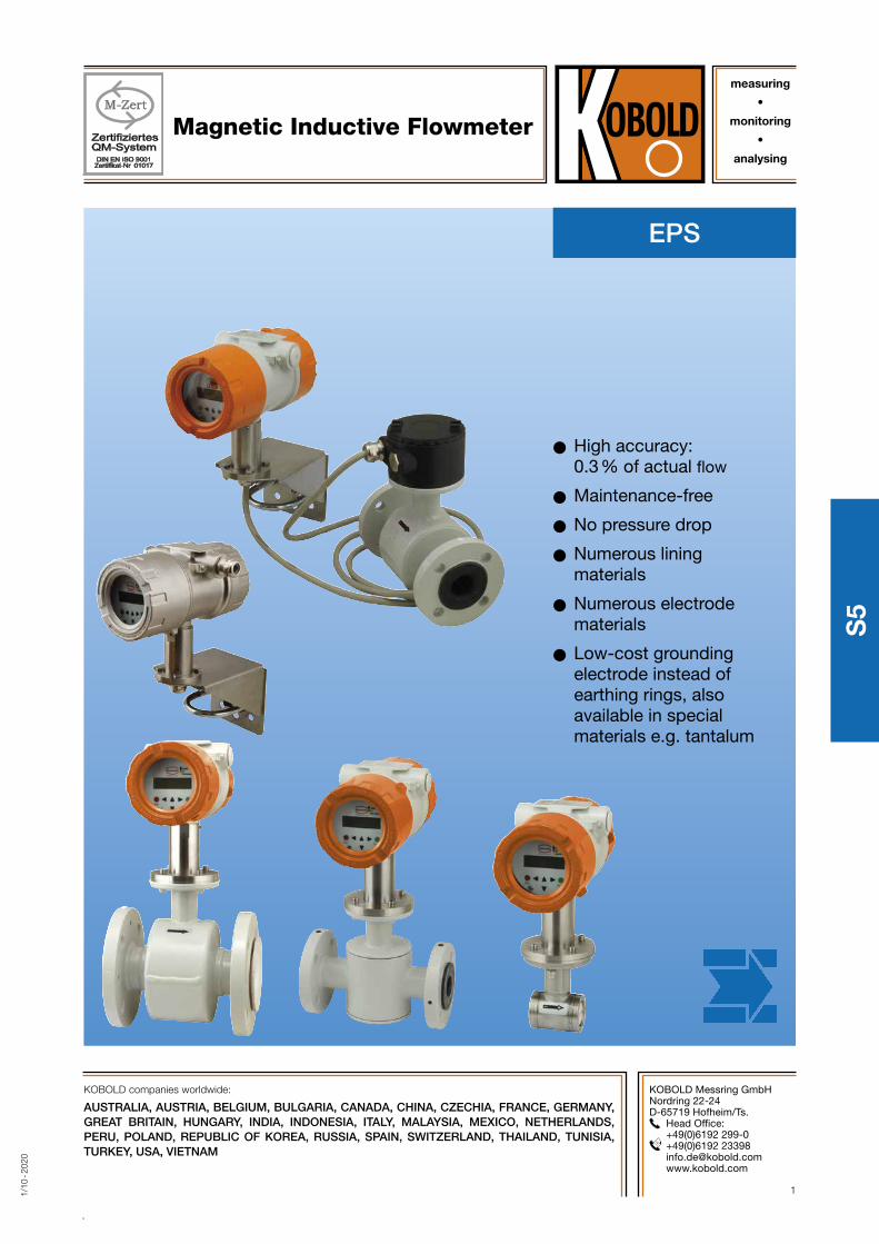
OO High accuracy: 0.3 % of actual flow
OO Maintenance-free
OO No pressure drop
OO Numerous lining materials
OO Numerous electrode materials
OO Low-cost grounding electrode instead of earthing rings, also available in special materials e.g. tantalum
KOBOLD companies worldwide:
AUSTRALIA, AUSTRIA, BELGIUM, BULGARIA, CANADA, CHINA, CZECHIA, FRANCE, GERMANY, GREAT BRITAIN, HUNGARY, INDIA, INDONESIA, ITALY, MALAYSIA, MEXICO, NETHERLANDS, PERU, POLAND, REPUBLIC OF KOREA, RUSSIA, SPAIN, SWITZERLAND, THAILAND, TUNISIA, TURKEY, USA, VIETNAM
2 www.kobold.com 1/1
0 - 2
020
No responsibility taken for errors; subject to change without prior notice.
Magnetic Inductive Flowmeter Model EPS
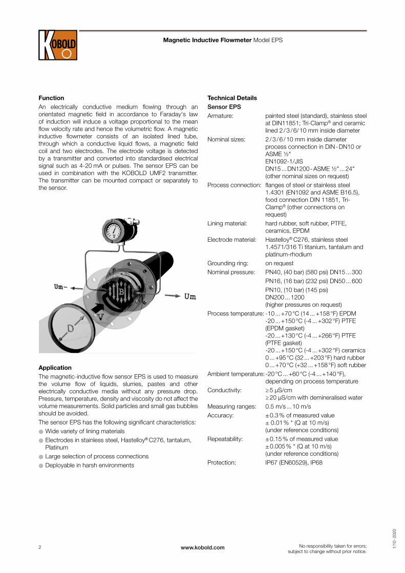
FunctionAn electrically conductive medium flowing through an orientated magnetic field in accordance to Faraday's law of induction will induce a voltage proportional to the mean flow velocity rate and hence the volumetric flow. A magnetic inductive flowmeter consists of an isolated lined tube, through which a conductive liquid flows, a magnetic field coil and two electrodes. The electrode voltage is detected by a transmitter and converted into standardised electrical signal such as 4-20 mA or pulses. The sensor EPS can be used in combination with the KOBOLD UMF2 transmitter. The transmitter can be mounted compact or separately to the sensor.
ApplicationThe magnetic-inductive flow sensor EPS is used to measure the volume flow of liquids, slurries, pastes and other electrically conductive media without any pressure drop. Pressure, temperature, density and viscosity do not affect the volume measurements. Solid particles and small gas bubbles should be avoided.The sensor EPS has the following significant characteristics:OO Wide variety of lining materialsOO Electrodes in stainless steel, Hastelloy® C276, tantalum, Platinum OO Large selection of process connectionsOO Deployable in harsh environments
Technical DetailsSensor EPSArmature: painted steel (standard), stainless steel
at DIN11851; Tri-Clamp® and ceramic lined 2 / 3 / 6/ 10 mm inside diameter
Nominal sizes: 2 / 3 / 6 / 10 mm inside diameter process connection in DIN - DN10 or ASME ½" EN1092-1/JIS DN15 ... DN1200 - ASME ½" ... 24" (other nominal sizes on request)
Process connection: flanges of steel or stainless steel 1.4301 (EN1092 and ASME B16.5), food connection DIN 11851, Tri-Clamp® (other connections on request)
Lining material: hard rubber, soft rubber, PTFE, ceramics, EPDM
Electrode material: Hastelloy® C276, stainless steel 1.4571/316 Ti titanium, tantalum and platinum-rhodium
Grounding ring: on requestNominal pressure: PN40, (40 bar) (580 psi) DN15 ... 300 PN16, (16 bar) (232 psi) DN50 ... 600 PN10, (10 bar) (145 psi)
DN200 ... 1200 (higher pressures on request)
Process temperature: -10 ... +70 °C (14 ... +158 °F) EPDM -20 ... +150 °C (-4 ... +302 °F) PTFE (EPDM gasket) -20 ... +130 °C (-4 ... +266 °F) PTFE (PTFE gasket) -20 ... +150 °C (-4 ... +302 °F) ceramics 0 ... +95 °C (32 ... +203 °F) hard rubber 0 ... +70 °C (+32 ... +158 °F) soft rubber
Ambient temperature: -20 °C ... +60 °C (-4 ... +140 °F), depending on process temperature
Conductivity: ≥ 5 µS/cm ≥ 20 µS/cm with demineralised water
Measuring ranges: 0.5 m/s ... 10 m/sAccuracy: ± 0.3 % of measured value
± 0.01 % * (Q at 10 m/s) (under reference conditions)
Repeatability: ± 0.15 % of measured value ± 0.005 % * (Q at 10 m/s) (under reference conditions)
Protection: IP67 (EN60529), IP68
3www.kobold.com 1/1
0 - 2
020
No responsibility taken for errors; subject to change without prior notice.
Magnetic Inductive Flowmeter Model EPS
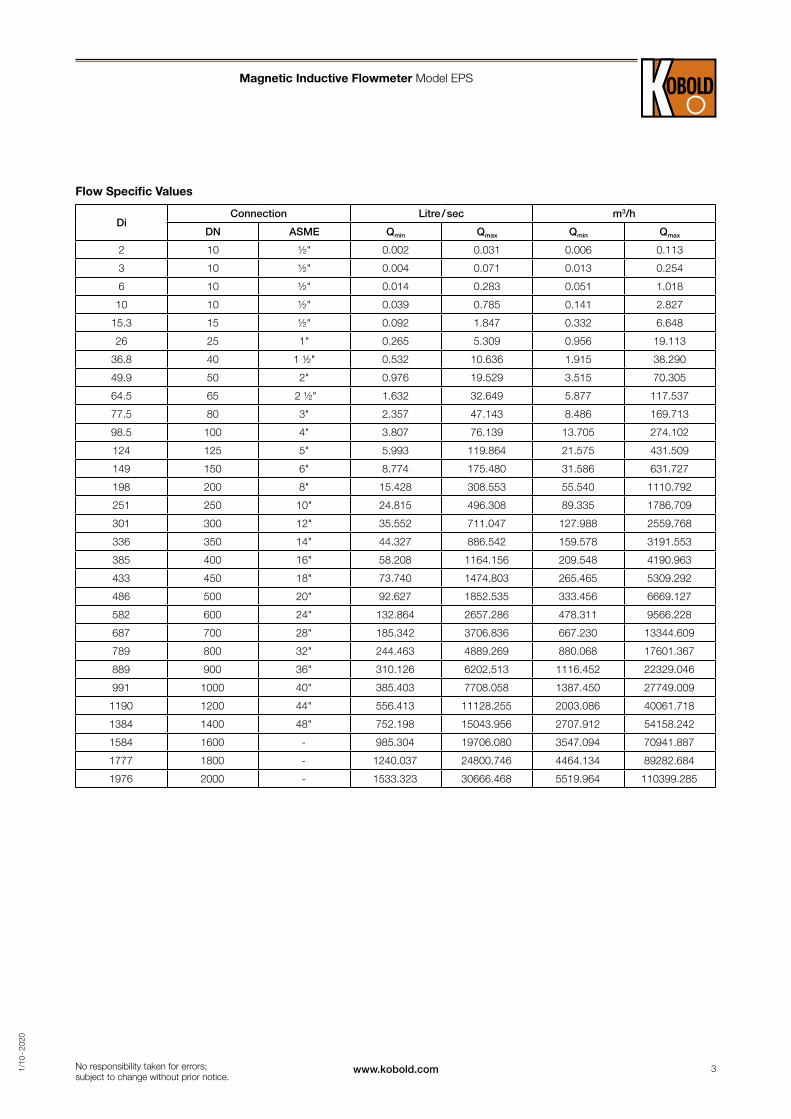
Flow Specific Values
DiConnection Litre / sec m3/h
DN ASME Qmin Qmax Qmin Qmax
2 10 ½" 0.002 0.031 0.006 0.113
3 10 ½" 0.004 0.071 0.013 0.254
6 10 ½" 0.014 0.283 0.051 1.018
10 10 ½" 0.039 0.785 0.141 2.827
15.3 15 ½" 0.092 1.847 0.332 6.648
26 25 1" 0.265 5.309 0.956 19.113
36.8 40 1 ½" 0.532 10.636 1.915 38.290
49.9 50 2" 0.976 19.529 3.515 70.305
64.5 65 2 ½" 1.632 32.649 5.877 117.537
77.5 80 3" 2.357 47.143 8.486 169.713
98.5 100 4" 3.807 76.139 13.705 274.102
124 125 5" 5.993 119.864 21.575 431.509
149 150 6" 8.774 175.480 31.586 631.727
198 200 8" 15.428 308.553 55.540 1110.792
251 250 10" 24.815 496.308 89.335 1786.709
301 300 12" 35.552 711.047 127.988 2559.768
336 350 14" 44.327 886.542 159.578 3191.553
385 400 16" 58.208 1164.156 209.548 4190.963
433 450 18" 73.740 1474.803 265.465 5309.292
486 500 20" 92.627 1852.535 333.456 6669.127
582 600 24" 132.864 2657.286 478.311 9566.228
687 700 28" 185.342 3706.836 667.230 13344.609
789 800 32" 244.463 4889.269 880.068 17601.367
889 900 36" 310.126 6202.513 1116.452 22329.046
991 1000 40" 385.403 7708.058 1387.450 27749.009
1190 1200 44" 556.413 11128.255 2003.086 40061.718
1384 1400 48" 752.198 15043.956 2707.912 54158.242
1584 1600 - 985.304 19706.080 3547.094 70941.887
1777 1800 - 1240.037 24800.746 4464.134 89282.684
1976 2000 - 1533.323 30666.468 5519.964 110399.285

4 www.kobold.com 1/1
0 - 2
020
Bitte neues Diagramm senden. Bei Erstellung des Diagramms aus dem PDF gibt es eine Fehlermeldung.
No responsibility taken for errors; subject to change without prior notice.
Accuracy± 0.3 % of measured value + 0.0001 * (Q at 10 m/s)
Repeatability± (0.15 % of measured value + 0.00005 * (Q at 10 m/s))
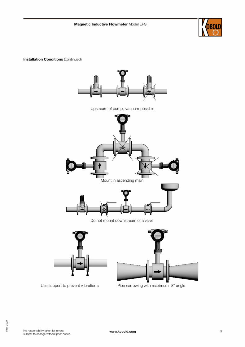
Installation ConditionsTo avoid vacuum, emptying of pipes or gas aggregation please take notice of the following mounting advice.
Emptying possible
Emptying avoided
Magnetic Inductive Flowmeter Model EPS
Accuracy
Flow velocity v [m/s]
5www.kobold.com 1/1
0 - 2
020
Upstream of pump, vacuum possible
Mount in ascending main
Do not mount downstream of a valve
Use support to prevent v ibrations Pipe narrowing with maximum 8° angle
No responsibility taken for errors; subject to change without prior notice.
Installation Conditions (continued)
Magnetic Inductive Flowmeter Model EPS
6 www.kobold.com 1/1
0 - 2
020
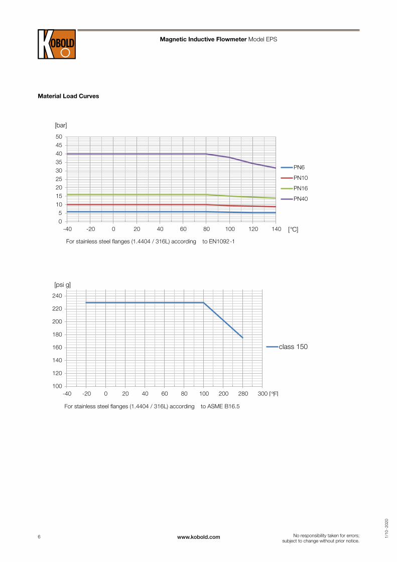
Material load curves
For stainless steel flanges (1.4404 / 316L) according to EN1092-1
For stainless steel flanges (1.4404 / 316L) according to ASME B16.5
05
101520253035404550
-40 -20 0 20 40 60 80 100 120 140
[bar]
PN6
PN10
PN16
PN40
[°C]
100
120
140
160
180
200
220
240
-40 -20 0 20 40 60 80 100 200 280 300
[psi g]
class 150
[°F]
No responsibility taken for errors; subject to change without prior notice.
Material Load Curves
Magnetic Inductive Flowmeter Model EPS
7www.kobold.com 1/1
0 - 2
020
20
25
30
35
40
45
50
55
60
65
70
60 70 80 90 100 110 120 130 140
[erutarepmet tneib
ma .xaM
°C]
Max. medium temperature [ °C]
40
45
50
55
60
65
70
70 80 90 100 110 120 130 140
[erutarepmet tneib
ma .xaM
°C]
Max. medium temperature [ °C]
20
25
30
35
40
45
50
55
60
65
70
60 70 80 90 100 110 120 130 140
[erutarepmet tneib
ma .xaM
°C]
Max. medium temperature [ °C]
40
45
50
55
60
65
70
70 80 90 100 110 120 130 140
[erutarepmet tneib
ma .xaM
°C]
Max. medium temperature [ °C]
No responsibility taken for errors; subject to change without prior notice.
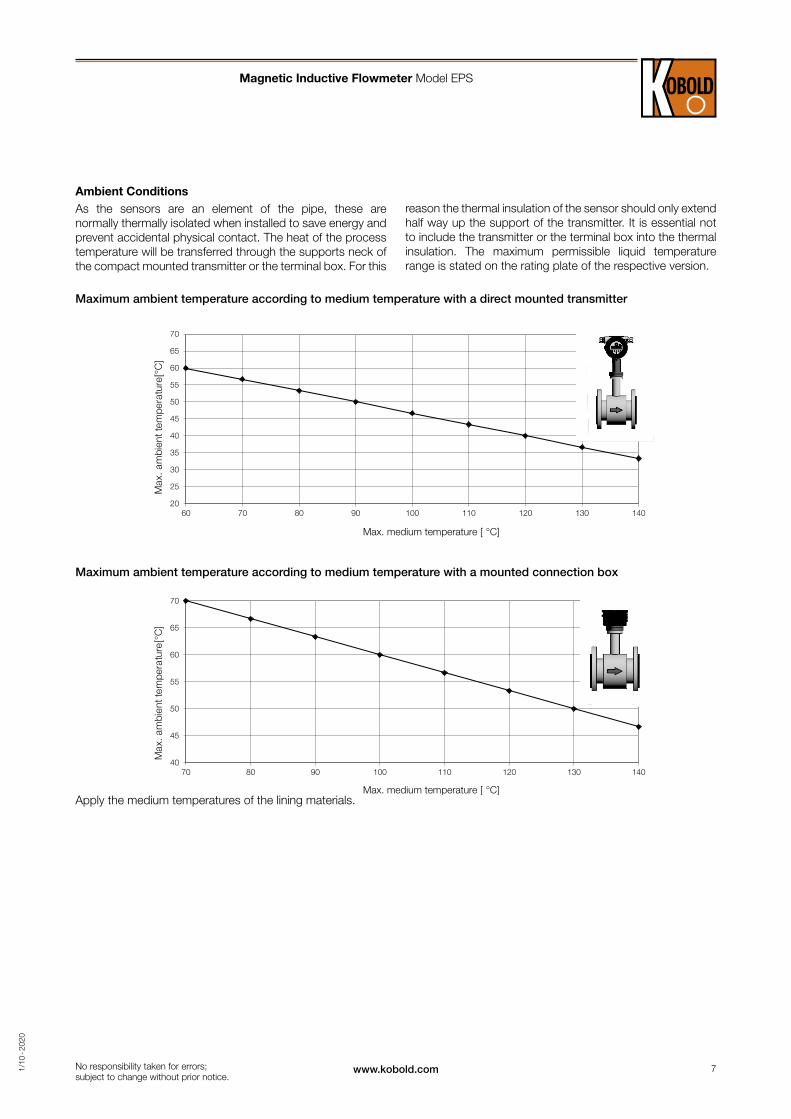
Ambient ConditionsAs the sensors are an element of the pipe, these are normally thermally isolated when installed to save energy and prevent accidental physical contact. The heat of the process temperature will be transferred through the supports neck of the compact mounted transmitter or the terminal box. For this
reason the thermal insulation of the sensor should only extend half way up the support of the transmitter. It is essential not to include the transmitter or the terminal box into the thermal insulation. The maximum permissible liquid temperature range is stated on the rating plate of the respective version.
Maximum ambient temperature according to medium temperature with a direct mounted transmitter
Maximum ambient temperature according to medium temperature with a mounted connection box
Apply the medium temperatures of the lining materials.
Magnetic Inductive Flowmeter Model EPS
8 www.kobold.com 1/1
0 - 2
020
No responsibility taken for errors; subject to change without prior notice.
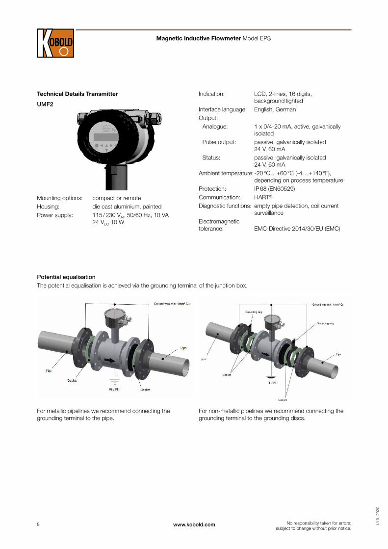
Technical Details Transmitter
UMF2
Mounting options: compact or remoteHousing: die cast aluminium, paintedPower supply: 115 / 230 VAC 50/60 Hz, 10 VA
24 VDC 10 W
Potential equalisationThe potential equalisation is achieved via the grounding terminal of the junction box.
For metallic pipelines we recommend connecting the grounding terminal to the pipe.
For non-metallic pipelines we recommend connecting the grounding terminal to the grounding discs.
Indication: LCD, 2-lines, 16 digits, background lighted
Interface language: English, GermanOutput: Analogue: 1 x 0/4-20 mA, active, galvanically
isolated Pulse output: passive, galvanically isolated
24 V, 60 mA Status: passive, galvanically isolated
24 V, 60 mAAmbient temperature: -20 °C ... +60 °C (-4 ... +140 °F),
depending on process temperatureProtection: IP 68 (EN60529)Communication: HART®
Diagnostic functions: empty pipe detection, coil current surveillance
Electromagnetic tolerance: EMC-Directive 2014/30/EU (EMC)
Magnetic Inductive Flowmeter Model EPS
9www.kobold.com 1/1
0 - 2
020
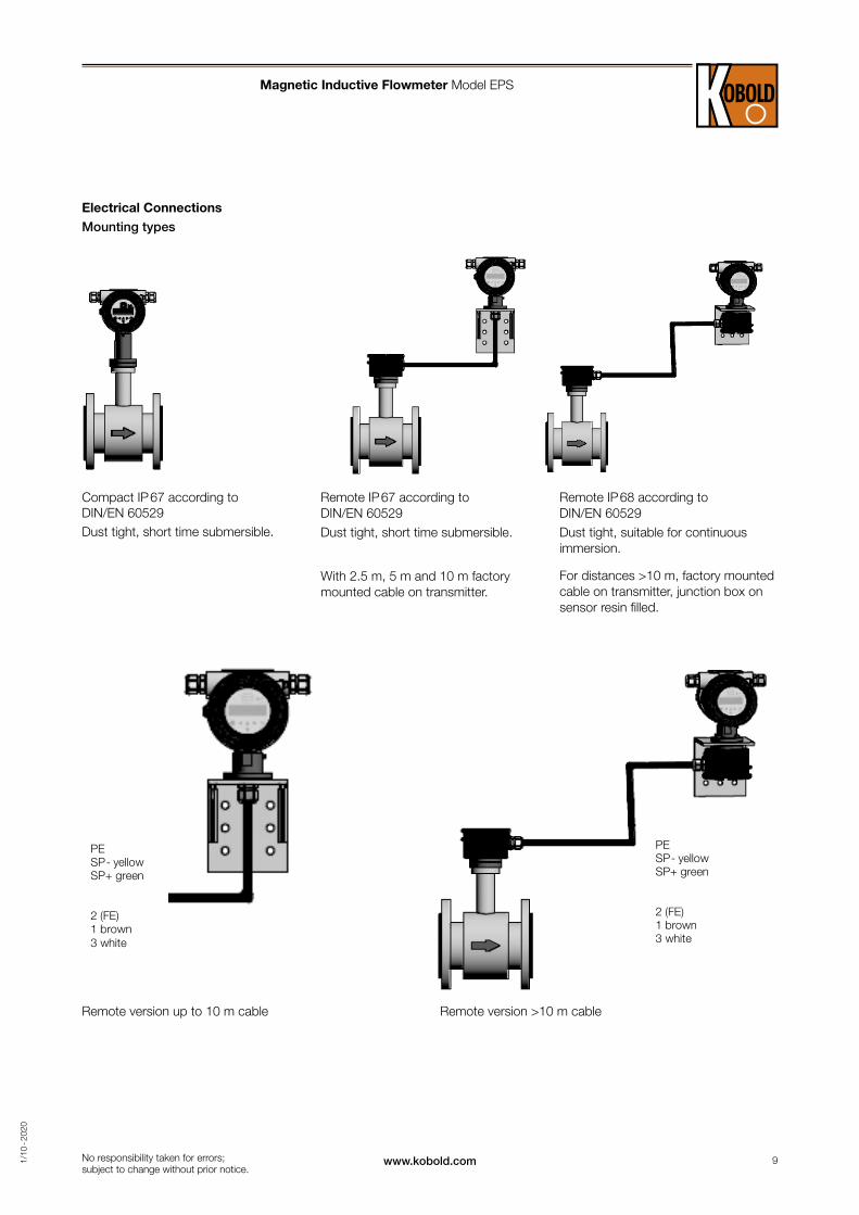
PE SP- yellow SP+ green 2 (FE) 1 brown 3 white
PE SP- yellow SP+ green 2 (FE) 1 brown 3 white
No responsibility taken for errors; subject to change without prior notice.
Electrical ConnectionsMounting types
Remote version up to 10 m cable Remote version >10 m cable
Compact IP 67 according to DIN/EN 60529Dust tight, short time submersible.
Remote IP 67 according to DIN/EN 60529Dust tight, short time submersible.
With 2.5 m, 5 m and 10 m factory mounted cable on transmitter.
Remote IP 68 according to DIN/EN 60529Dust tight, suitable for continuous immersion.
For distances >10 m, factory mounted cable on transmitter, junction box on sensor resin filled.
Magnetic Inductive Flowmeter Model EPS
10 www.kobold.com 1/1
0 - 2
020
No responsibility taken for errors; subject to change without prior notice.
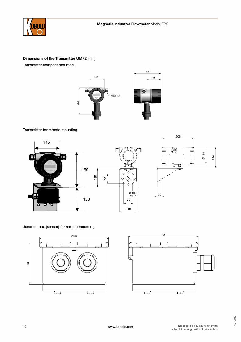
Dimensions of the Transmitter UMF2 [mm]
Transmitter compact mounted
Transmitter for remote mounting
Junction box (sensor) for remote mounting
Magnetic Inductive Flowmeter Model EPS
11www.kobold.com 1/1
0 - 2
020
D
A‘
D
E
D
A‘
D
E
No responsibility taken for errors; subject to change without prior notice.
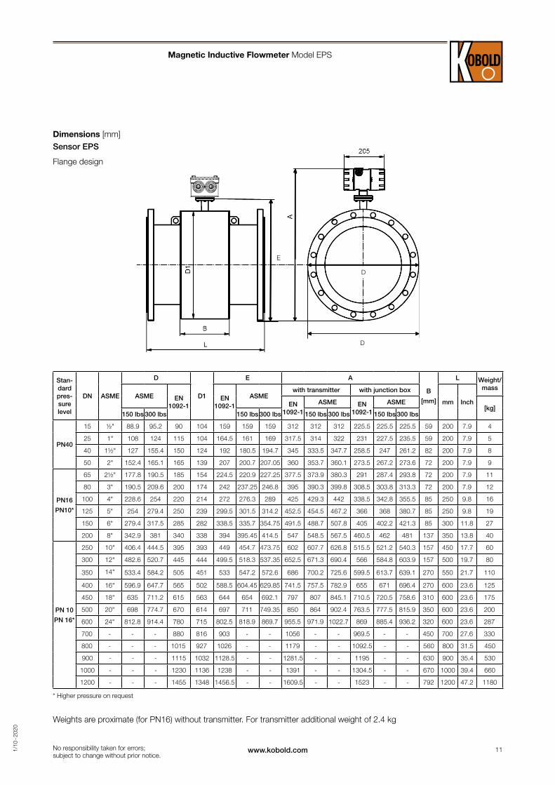
Dimensions [mm]Sensor EPS
Flange design
Magnetic Inductive Flowmeter Model EPS
Stan-dard pres-sure level
DN ASME
D
D1
E A
B
[mm]
L Weight/ mass
ASME EN 1092-1
EN 1092-1
ASMEwith transmitter with junction box
mm InchEN 1092-1
ASME EN 1092-1
ASME[kg]
150 lbs 300 lbs 150 lbs 300 lbs 150 lbs 300 lbs 150 lbs 300 lbs
PN40
15 ½" 88.9 95.2 90 104 159 159 159 312 312 312 225.5 225.5 225.5 59 200 7.9 4
25 1" 108 124 115 104 164.5 161 169 317.5 314 322 231 227.5 235.5 59 200 7.9 5
40 1½" 127 155.4 150 124 192 180.5 194.7 345 333.5 347.7 258.5 247 261.2 82 200 7.9 8
50 2" 152.4 165.1 165 139 207 200.7 207.05 360 353.7 360.1 273.5 267.2 273.6 72 200 7.9 9
PN16
PN10*
65 2½" 177.8 190.5 185 154 224.5 220.9 227.25 377.5 373.9 380.3 291 287.4 293.8 72 200 7.9 11
80 3" 190.5 209.6 200 174 242 237.25 246.8 395 390.3 399.8 308.5 303.8 313.3 72 200 7.9 12
100 4" 228.6 254 220 214 272 276.3 289 425 429.3 442 338.5 342.8 355.5 85 250 9.8 16
125 5" 254 279.4 250 239 299.5 301.5 314.2 452.5 454.5 467.2 366 368 380.7 85 250 9.8 19
150 6" 279.4 317.5 285 282 338.5 335.7 354.75 491.5 488.7 507.8 405 402.2 421.3 85 300 11.8 27
200 8" 342.9 381 340 338 394 395.45 414.5 547 548.5 567.5 460.5 462 481 137 350 13.8 40
PN 10
PN 16*
250 10" 406.4 444.5 395 393 449 454.7 473.75 602 607.7 626.8 515.5 521.2 540.3 157 450 17.7 60
300 12" 482.6 520.7 445 444 499.5 518.3 537.35 652.5 671.3 690.4 566 584.8 603.9 157 500 19.7 80
350 14" 533.4 584.2 505 451 533 547.2 572.6 686 700.2 725.6 599.5 613.7 639.1 270 550 21.7 110
400 16" 596.9 647.7 565 502 588.5 604.45 629.85 741.5 757.5 782.9 655 671 696.4 270 600 23.6 125
450 18" 635 711.2 615 563 644 654 692.1 797 807 845.1 710.5 720.5 758.6 310 600 23.6 175
500 20" 698 774.7 670 614 697 711 749.35 850 864 902.4 763.5 777.5 815.9 350 600 23.6 200
600 24" 812.8 914.4 780 715 802.5 818.9 869.7 955.5 971.9 1022.7 869 885.4 936.2 320 600 23.6 287
700 - - - 880 816 903 - - 1056 - - 969.5 - - 450 700 27.6 330
800 - - - 1015 927 1026 - - 1179 - - 1092.5 - - 560 800 31.5 450
900 - - - 1115 1032 1128.5 - - 1281.5 - - 1195 - - 630 900 35.4 530
1000 - - - 1230 1136 1238 - - 1391 - - 1304.5 - - 670 1000 39.4 660
1200 - - - 1455 1348 1456.5 - - 1609.5 - - 1523 - - 792 1200 47.2 1180
* Higher pressure on request
Weights are proximate (for PN16) without transmitter. For transmitter additional weight of 2.4 kg
12 www.kobold.com 1/1
0 - 2
020
G ½ (ISO) or ½“ NPT
35
20
6 x M4
52 mm
B
C
No responsibility taken for errors; subject to change without prior notice.
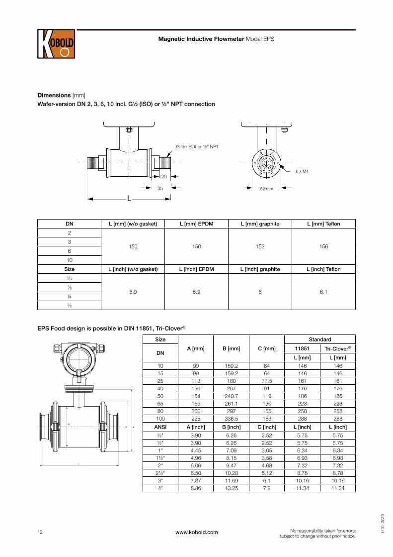
Dimensions [mm]Wafer-version DN 2, 3, 6, 10 incl. G½ (ISO) or ½" NPT connection
DN L [mm] (w/o gasket) L [mm] EPDM L [mm] graphite L [mm] Teflon
2
150 150 152 1563
6
10
Size L [inch] (w/o gasket) L [inch] EPDM L [inch] graphite L [inch] Teflon1⁄12
5.9 5.9 6 6.11⁄8
¼3⁄8
Magnetic Inductive Flowmeter Model EPS
EPS Food design is possible in DIN 11851, Tri-Clover®
Size
A [mm] B [mm] C [mm]
Standard
DN11851 Tri-Clover®
L [mm] L [mm]
10 99 159.2 64 146 14615 99 159.2 64 146 14625 113 180 77.5 161 16140 126 207 91 176 17650 154 240.7 119 186 18665 165 261.1 130 223 22380 200 297 155 258 258100 225 336.5 183 288 288
ANSI A [inch] B [inch] C [inch] L [inch] L [inch]3⁄8" 3.90 6.26 2.52 5.75 5.75½" 3.90 6.26 2.52 5.75 5.751" 4.45 7.09 3.05 6.34 6.34
1½" 4.96 8.15 3.58 6.93 6.932" 6.06 9.47 4.68 7.32 7.32
2½" 6.50 10.28 5.12 8.78 8.783" 7.87 11.69 6.1 10.16 10.164" 8.86 13.25 7.2 11.34 11.34
13www.kobold.com 1/1
0 - 2
020
No responsibility taken for errors; subject to change without prior notice.
Magnetic Inductive Flowmeter Model EPS
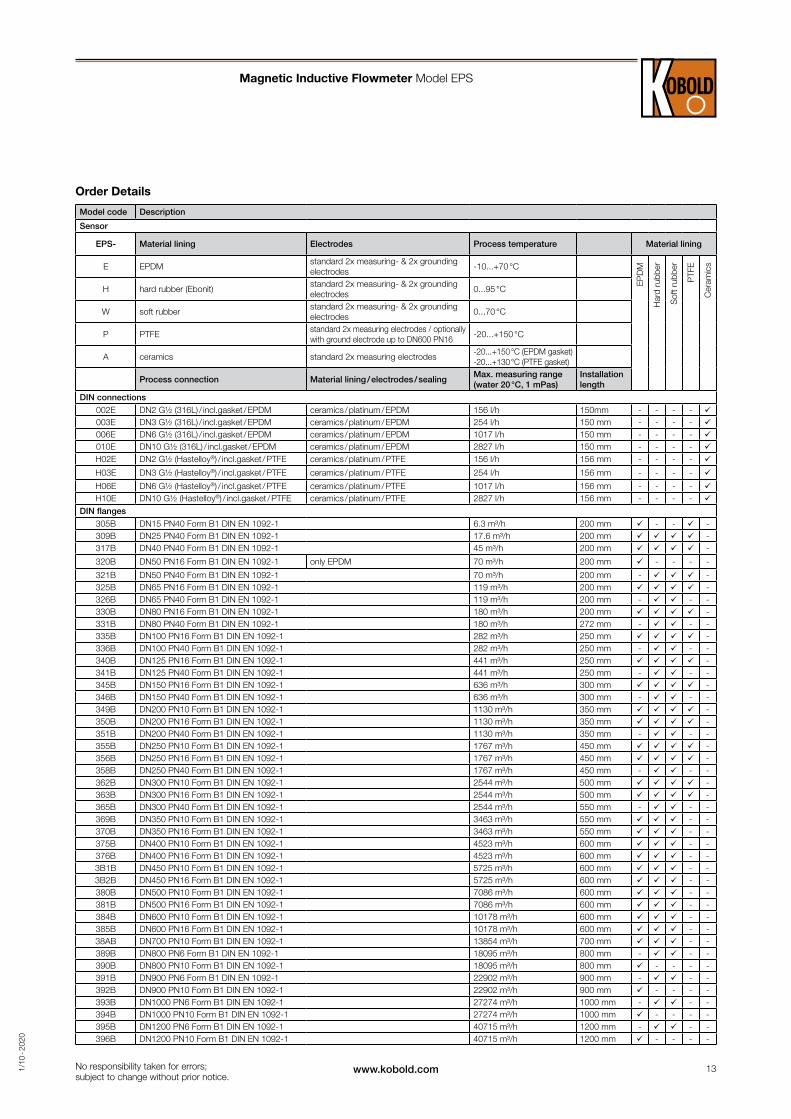
Order Details
Model code Description
Sensor
EPS- Material lining Electrodes Process temperature Material lining
E EPDMstandard 2x measuring- & 2x grounding electrodes
-10...+70 °C
EP
DM
Har
d ru
bber
Sof
t rub
ber
PTF
E
Cer
amic
s
H hard rubber (Ebonit)standard 2x measuring- & 2x grounding electrodes
0...95 °C
W soft rubberstandard 2x measuring- & 2x grounding electrodes
0...70 °C
P PTFEstandard 2x measuring electrodes / optionally with ground electrode up to DN600 PN16
-20...+150 °C
A ceramics standard 2x measuring electrodes-20...+150 °C (EPDM gasket) -20...+130 °C (PTFE gasket)
Process connection Material lining / electrodes / sealingMax. measuring range (water 20 °C, 1 mPas)
Installation length
DIN connections
002E DN2 G½ (316L) / incl.gasket / EPDM ceramics / platinum / EPDM 156 l/h 150mm - - - - 003E DN3 G½ (316L) / incl.gasket / EPDM ceramics / platinum / EPDM 254 l/h 150 mm - - - - 006E DN6 G½ (316L) / incl.gasket / EPDM ceramics / platinum / EPDM 1017 l/h 150 mm - - - - 010E DN10 G½ (316L) / incl.gasket / EPDM ceramics / platinum / EPDM 2827 l/h 150 mm - - - -
H02E DN2 G½ (Hastelloy®) / incl.gasket / PTFE ceramics / platinum / PTFE 156 l/h 156 mm - - - -
H03E DN3 G½ (Hastelloy®) / incl.gasket / PTFE ceramics / platinum / PTFE 254 l/h 156 mm - - - -
H06E DN6 G½ (Hastelloy®) / incl.gasket / PTFE ceramics / platinum / PTFE 1017 l/h 156 mm - - - - H10E DN10 G½ (Hastelloy®) / incl.gasket / PTFE ceramics / platinum / PTFE 2827 l/h 156 mm - - - -
DIN flanges
305B DN15 PN40 Form B1 DIN EN 1092-1 6.3 m³/h 200 mm - - -309B DN25 PN40 Form B1 DIN EN 1092-1 17.6 m³/h 200 mm -317B DN40 PN40 Form B1 DIN EN 1092-1 45 m³/h 200 mm -
320B DN50 PN16 Form B1 DIN EN 1092-1 only EPDM 70 m³/h 200 mm - - - -
321B DN50 PN40 Form B1 DIN EN 1092-1 70 m³/h 200 mm - -325B DN65 PN16 Form B1 DIN EN 1092-1 119 m³/h 200 mm -326B DN65 PN40 Form B1 DIN EN 1092-1 119 m³/h 200 mm - - -330B DN80 PN16 Form B1 DIN EN 1092-1 180 m³/h 200 mm -331B DN80 PN40 Form B1 DIN EN 1092-1 180 m³/h 272 mm - - -335B DN100 PN16 Form B1 DIN EN 1092-1 282 m³/h 250 mm -336B DN100 PN40 Form B1 DIN EN 1092-1 282 m³/h 250 mm - - -340B DN125 PN16 Form B1 DIN EN 1092-1 441 m³/h 250 mm -341B DN125 PN40 Form B1 DIN EN 1092-1 441 m³/h 250 mm - - -345B DN150 PN16 Form B1 DIN EN 1092-1 636 m³/h 300 mm -346B DN150 PN40 Form B1 DIN EN 1092-1 636 m³/h 300 mm - - -349B DN200 PN10 Form B1 DIN EN 1092-1 1130 m³/h 350 mm -350B DN200 PN16 Form B1 DIN EN 1092-1 1130 m³/h 350 mm -351B DN200 PN40 Form B1 DIN EN 1092-1 1130 m³/h 350 mm - - -355B DN250 PN10 Form B1 DIN EN 1092-1 1767 m³/h 450 mm -356B DN250 PN16 Form B1 DIN EN 1092-1 1767 m³/h 450 mm -358B DN250 PN40 Form B1 DIN EN 1092-1 1767 m³/h 450 mm - - -362B DN300 PN10 Form B1 DIN EN 1092-1 2544 m³/h 500 mm -363B DN300 PN16 Form B1 DIN EN 1092-1 2544 m³/h 500 mm -365B DN300 PN40 Form B1 DIN EN 1092-1 2544 m³/h 550 mm - - -369B DN350 PN10 Form B1 DIN EN 1092-1 3463 m³/h 550 mm - -370B DN350 PN16 Form B1 DIN EN 1092-1 3463 m³/h 550 mm - -375B DN400 PN10 Form B1 DIN EN 1092-1 4523 m³/h 600 mm - -376B DN400 PN16 Form B1 DIN EN 1092-1 4523 m³/h 600 mm - -3B1B DN450 PN10 Form B1 DIN EN 1092-1 5725 m³/h 600 mm - -3B2B DN450 PN16 Form B1 DIN EN 1092-1 5725 m³/h 600 mm - -380B DN500 PN10 Form B1 DIN EN 1092-1 7086 m³/h 600 mm - -381B DN500 PN16 Form B1 DIN EN 1092-1 7086 m³/h 600 mm - -384B DN600 PN10 Form B1 DIN EN 1092-1 10178 m³/h 600 mm - -385B DN600 PN16 Form B1 DIN EN 1092-1 10178 m³/h 600 mm - -38AB DN700 PN10 Form B1 DIN EN 1092-1 13854 m³/h 700 mm - -389B DN800 PN6 Form B1 DIN EN 1092-1 18095 m³/h 800 mm - - -390B DN800 PN10 Form B1 DIN EN 1092-1 18095 m³/h 800 mm - - - -391B DN900 PN6 Form B1 DIN EN 1092-1 22902 m³/h 900 mm - - -392B DN900 PN10 Form B1 DIN EN 1092-1 22902 m³/h 900 mm - - - -393B DN1000 PN6 Form B1 DIN EN 1092-1 27274 m³/h 1000 mm - - -394B DN1000 PN10 Form B1 DIN EN 1092-1 27274 m³/h 1000 mm - - - -395B DN1200 PN6 Form B1 DIN EN 1092-1 40715 m³/h 1200 mm - - -396B DN1200 PN10 Form B1 DIN EN 1092-1 40715 m³/h 1200 mm - - - -
14 www.kobold.com 1/1
0 - 2
020
No responsibility taken for errors; subject to change without prior notice.
Magnetic Inductive Flowmeter Model EPS
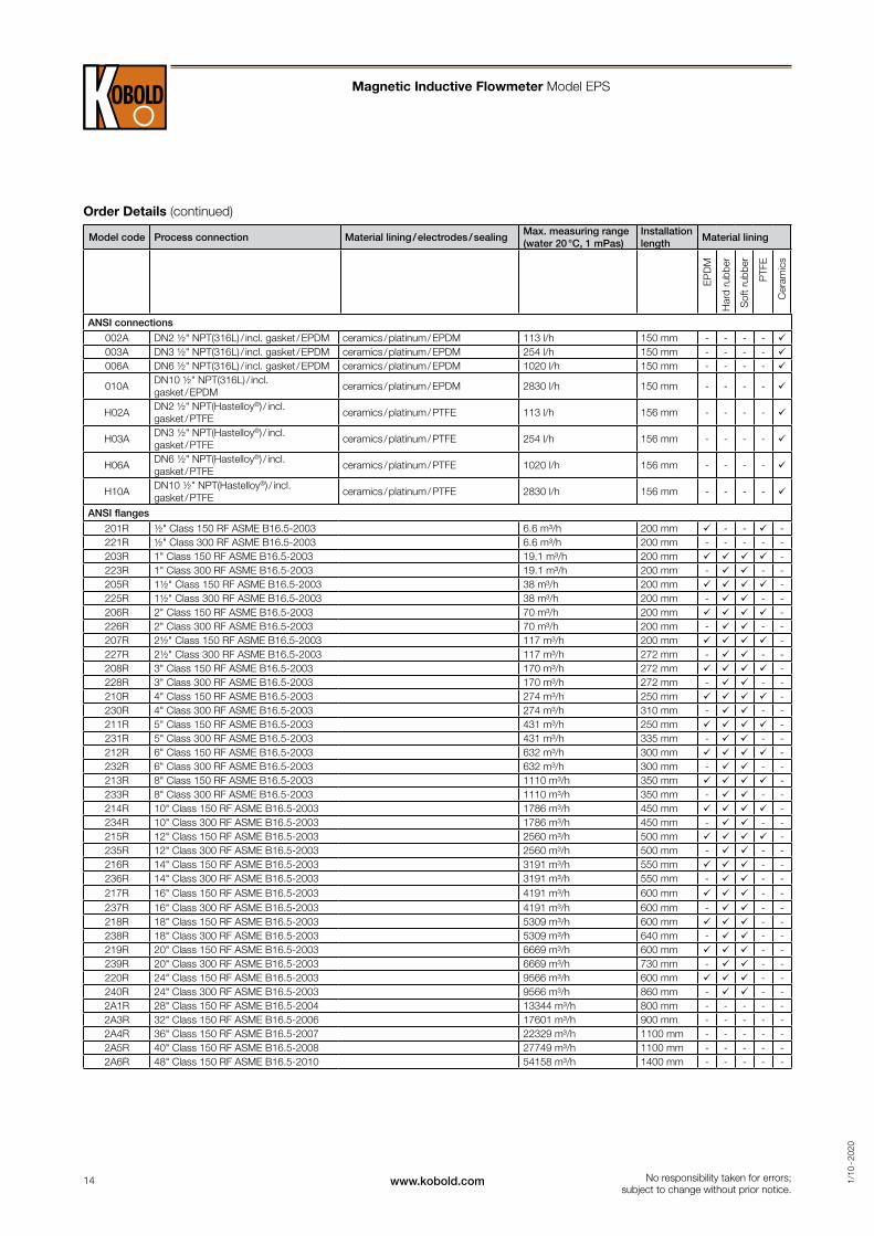
Order Details (continued)
Model code Process connection Material lining / electrodes / sealingMax. measuring range (water 20 °C, 1 mPas)
Installation length
Material lining
EP
DM
Har
d ru
bber
Sof
t rub
ber
PTF
E
Cer
amic
s
ANSI connections
002A DN2 ½" NPT(316L) / incl. gasket / EPDM ceramics / platinum / EPDM 113 l/h 150 mm - - - - 003A DN3 ½" NPT(316L) / incl. gasket / EPDM ceramics / platinum / EPDM 254 l/h 150 mm - - - - 006A DN6 ½" NPT(316L) / incl. gasket / EPDM ceramics / platinum / EPDM 1020 l/h 150 mm - - - -
010ADN10 ½" NPT(316L) / incl. gasket / EPDM
ceramics / platinum / EPDM 2830 l/h 150 mm - - - -
H02ADN2 ½" NPT(Hastelloy®) / incl. gasket / PTFE
ceramics / platinum / PTFE 113 l/h 156 mm - - - -
H03ADN3 ½" NPT(Hastelloy®) / incl. gasket / PTFE
ceramics / platinum / PTFE 254 l/h 156 mm - - - -
H06ADN6 ½" NPT(Hastelloy®) / incl. gasket / PTFE
ceramics / platinum / PTFE 1020 l/h 156 mm - - - -
H10ADN10 ½" NPT(Hastelloy®) / incl. gasket / PTFE
ceramics / platinum / PTFE 2830 l/h 156 mm - - - -
ANSI flanges
201R ½" Class 150 RF ASME B16.5-2003 6.6 m³/h 200 mm - - -221R ½" Class 300 RF ASME B16.5-2003 6.6 m³/h 200 mm - - - - -203R 1" Class 150 RF ASME B16.5-2003 19.1 m³/h 200 mm -223R 1" Class 300 RF ASME B16.5-2003 19.1 m³/h 200 mm - - -205R 1½" Class 150 RF ASME B16.5-2003 38 m³/h 200 mm -225R 1½" Class 300 RF ASME B16.5-2003 38 m³/h 200 mm - - -206R 2" Class 150 RF ASME B16.5-2003 70 m³/h 200 mm -226R 2" Class 300 RF ASME B16.5-2003 70 m³/h 200 mm - - -207R 2½" Class 150 RF ASME B16.5-2003 117 m³/h 200 mm -227R 2½" Class 300 RF ASME B16.5-2003 117 m³/h 272 mm - - -208R 3" Class 150 RF ASME B16.5-2003 170 m³/h 272 mm -228R 3" Class 300 RF ASME B16.5-2003 170 m³/h 272 mm - - -210R 4" Class 150 RF ASME B16.5-2003 274 m³/h 250 mm -230R 4" Class 300 RF ASME B16.5-2003 274 m³/h 310 mm - - -211R 5" Class 150 RF ASME B16.5-2003 431 m³/h 250 mm -231R 5" Class 300 RF ASME B16.5-2003 431 m³/h 335 mm - - -212R 6" Class 150 RF ASME B16.5-2003 632 m³/h 300 mm -232R 6" Class 300 RF ASME B16.5-2003 632 m³/h 300 mm - - -213R 8" Class 150 RF ASME B16.5-2003 1110 m³/h 350 mm -233R 8" Class 300 RF ASME B16.5-2003 1110 m³/h 350 mm - - -214R 10" Class 150 RF ASME B16.5-2003 1786 m³/h 450 mm -234R 10" Class 300 RF ASME B16.5-2003 1786 m³/h 450 mm - - -215R 12" Class 150 RF ASME B16.5-2003 2560 m³/h 500 mm -235R 12" Class 300 RF ASME B16.5-2003 2560 m³/h 500 mm - - -216R 14" Class 150 RF ASME B16.5-2003 3191 m³/h 550 mm - -236R 14" Class 300 RF ASME B16.5-2003 3191 m³/h 550 mm - - -217R 16" Class 150 RF ASME B16.5-2003 4191 m³/h 600 mm - -237R 16" Class 300 RF ASME B16.5-2003 4191 m³/h 600 mm - - -218R 18" Class 150 RF ASME B16.5-2003 5309 m³/h 600 mm - -238R 18" Class 300 RF ASME B16.5-2003 5309 m³/h 640 mm - - -219R 20" Class 150 RF ASME B16.5-2003 6669 m³/h 600 mm - -239R 20" Class 300 RF ASME B16.5-2003 6669 m³/h 730 mm - - -220R 24" Class 150 RF ASME B16.5-2003 9566 m³/h 600 mm - -240R 24" Class 300 RF ASME B16.5-2003 9566 m³/h 860 mm - - -2A1R 28" Class 150 RF ASME B16.5-2004 13344 m³/h 800 mm - - - - -2A3R 32" Class 150 RF ASME B16.5-2006 17601 m³/h 900 mm - - - - -2A4R 36" Class 150 RF ASME B16.5-2007 22329 m³/h 1100 mm - - - - -2A5R 40" Class 150 RF ASME B16.5-2008 27749 m³/h 1100 mm - - - - -2A6R 48" Class 150 RF ASME B16.5-2010 54158 m³/h 1400 mm - - - - -
15www.kobold.com 1/1
0 - 2
020
No responsibility taken for errors; subject to change without prior notice.
Magnetic Inductive Flowmeter Model EPS
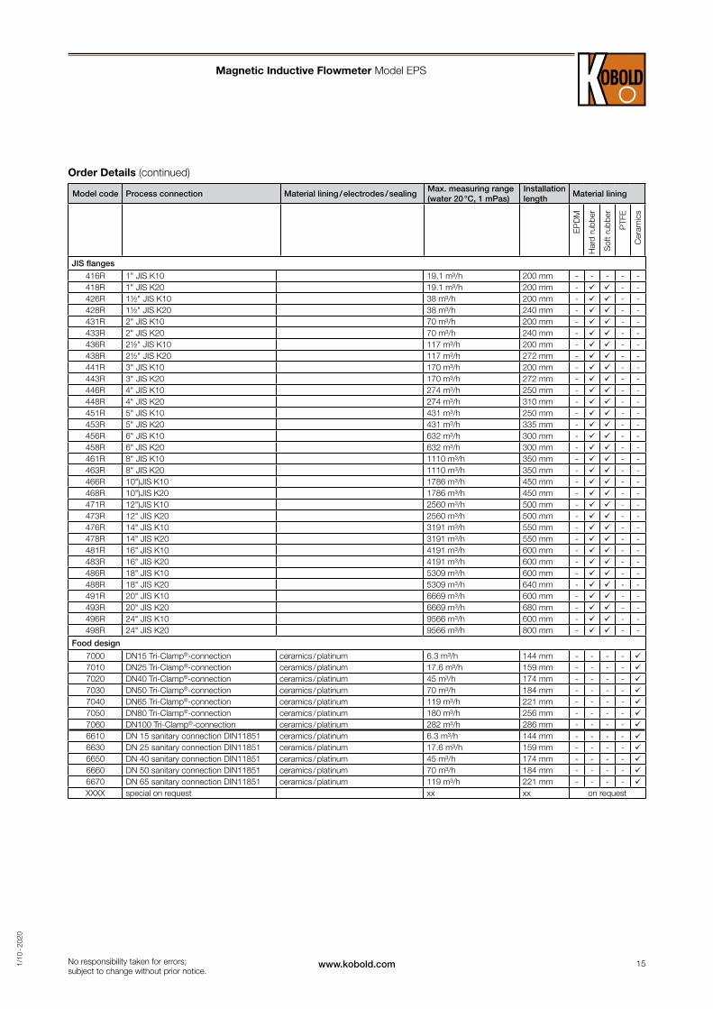
Order Details (continued)
Model code Process connection Material lining / electrodes / sealingMax. measuring range (water 20 °C, 1 mPas)
Installation length
Material lining
EP
DM
Har
d ru
bber
Sof
t rub
ber
PTF
E
Cer
amic
s
JIS flanges
416R 1" JIS K10 19.1 m³/h 200 mm - - - - -418R 1" JIS K20 19.1 m³/h 200 mm - - -426R 1½" JIS K10 38 m³/h 200 mm - - -428R 1½" JIS K20 38 m³/h 240 mm - - -431R 2" JIS K10 70 m³/h 200 mm - - -433R 2" JIS K20 70 m³/h 240 mm - - -436R 2½" JIS K10 117 m³/h 200 mm - - -438R 2½" JIS K20 117 m³/h 272 mm - - -441R 3" JIS K10 170 m³/h 200 mm - - -443R 3" JIS K20 170 m³/h 272 mm - - -446R 4" JIS K10 274 m³/h 250 mm - - -448R 4" JIS K20 274 m³/h 310 mm - - -451R 5" JIS K10 431 m³/h 250 mm - - -453R 5" JIS K20 431 m³/h 335 mm - - -456R 6" JIS K10 632 m³/h 300 mm - - -458R 6" JIS K20 632 m³/h 300 mm - - -461R 8" JIS K10 1110 m³/h 350 mm - - -463R 8" JIS K20 1110 m³/h 350 mm - - -466R 10")JIS K10 1786 m³/h 450 mm - - -468R 10")JIS K20 1786 m³/h 450 mm - - -471R 12")JIS K10 2560 m³/h 500 mm - - -473R 12" JIS K20 2560 m³/h 500 mm - - -476R 14" JIS K10 3191 m³/h 550 mm - - -478R 14" JIS K20 3191 m³/h 550 mm - - -481R 16" JIS K10 4191 m³/h 600 mm - - -483R 16" JIS K20 4191 m³/h 600 mm - - -486R 18" JIS K10 5309 m³/h 600 mm - - -488R 18" JIS K20 5309 m³/h 640 mm - - -491R 20" JIS K10 6669 m³/h 600 mm - - -493R 20" JIS K20 6669 m³/h 680 mm - - -496R 24" JIS K10 9566 m³/h 600 mm - - -498R 24" JIS K20 9566 m³/h 800 mm - - -
Food design
7000 DN15 Tri-Clamp®-connection ceramics / platinum 6.3 m³/h 144 mm - - - - 7010 DN25 Tri-Clamp®-connection ceramics / platinum 17.6 m³/h 159 mm - - - - 7020 DN40 Tri-Clamp®-connection ceramics / platinum 45 m³/h 174 mm - - - - 7030 DN50 Tri-Clamp®-connection ceramics / platinum 70 m³/h 184 mm - - - - 7040 DN65 Tri-Clamp®-connection ceramics / platinum 119 m³/h 221 mm - - - - 7050 DN80 Tri-Clamp®-connection ceramics / platinum 180 m³/h 256 mm - - - - 7060 DN100 Tri-Clamp®-connection ceramics / platinum 282 m³/h 286 mm - - - - 6610 DN 15 sanitary connection DIN11851 ceramics / platinum 6.3 m³/h 144 mm - - - - 6630 DN 25 sanitary connection DIN11851 ceramics / platinum 17.6 m³/h 159 mm - - - - 6650 DN 40 sanitary connection DIN11851 ceramics / platinum 45 m³/h 174 mm - - - - 6660 DN 50 sanitary connection DIN11851 ceramics / platinum 70 m³/h 184 mm - - - - 6670 DN 65 sanitary connection DIN11851 ceramics / platinum 119 m³/h 221 mm - - - - XXXX special on request xx xx on request
16 www.kobold.com 1/1
0 - 2
020
No responsibility taken for errors; subject to change without prior notice.
Magnetic Inductive Flowmeter Model EPS
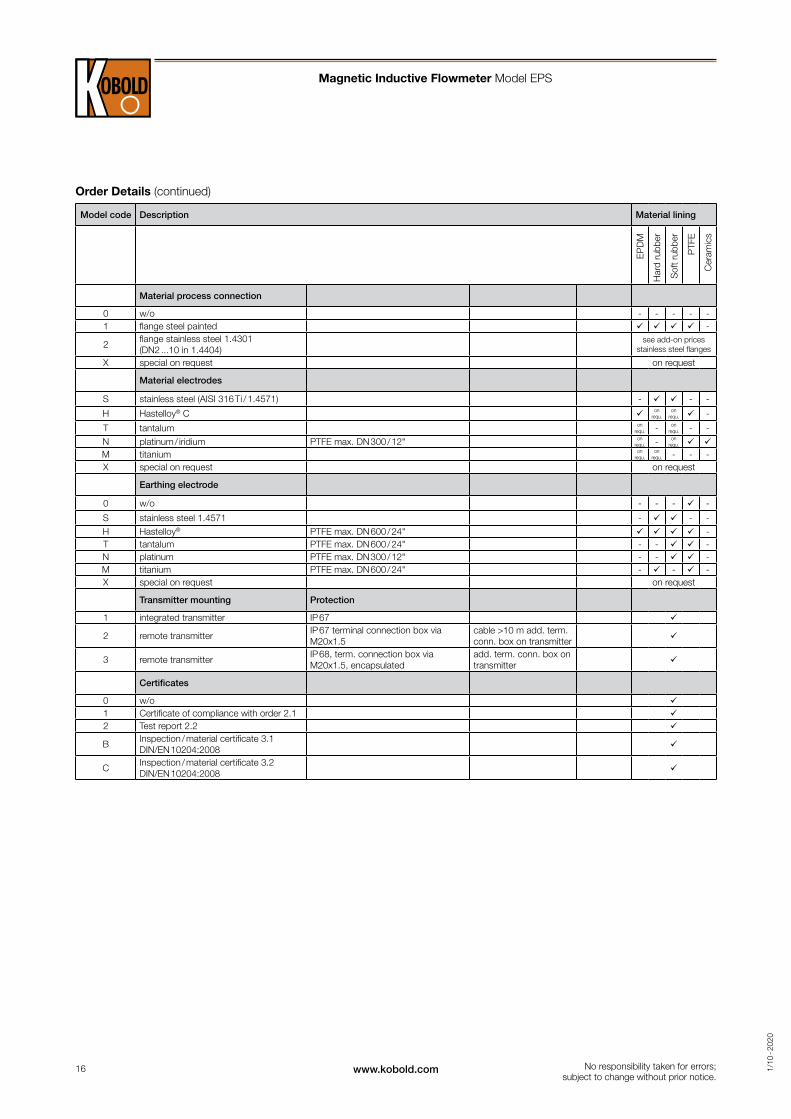
Order Details (continued)
Material process connection
0 w/o - - - - -1 flange steel painted -
2flange stainless steel 1.4301 (DN2 ...10 in 1.4404)
see add-on prices stainless steel flanges
X special on request on request
Material electrodes
S stainless steel (AISI 316 Ti / 1.4571) - - -
H Hastelloy® C on requ.
on requ. -
T tantalum on requ. - on
requ. - -N platinum / iridium PTFE max. DN 300 / 12" on
requ. - on requ.
M titanium on requ.
on requ. - - -
X special on request on request
Earthing electrode
0 w/o - - - -
S stainless steel 1.4571 - - -H Hastelloy® PTFE max. DN 600 / 24" -T tantalum PTFE max. DN 600 / 24" - - -N platinum PTFE max. DN 300 / 12" - - -M titanium PTFE max. DN 600 / 24" - - -X special on request on request
Transmitter mounting Protection
1 integrated transmitter IP 67
2 remote transmitterIP 67 terminal connection box via M20x1.5
cable >10 m add. term. conn. box on transmitter
3 remote transmitterIP 68, term. connection box via M20x1.5, encapsulated
add. term. conn. box on transmitter
Certificates
0 w/o 1 Certificate of compliance with order 2.1 2 Test report 2.2
BInspection / material certificate 3.1 DIN/EN 10204:2008
CInspection / material certificate 3.2 DIN/EN 10204:2008
Model code Description Material lining
EP
DM
Har
d ru
bber
Sof
t rub
ber
PTF
E
Cer
amic
s
17www.kobold.com 1/1
0 - 2
020
No responsibility taken for errors; subject to change without prior notice.
Magnetic Inductive Flowmeter Model EPS
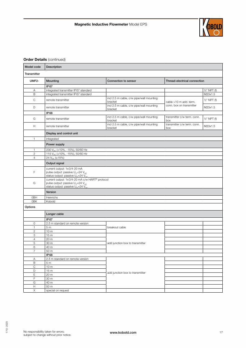
Order Details (continued)
Model code Description
Transmitter
UMF2- Mounting Connection to sensor Thread-electrical connection
IP 67A integrated transmitter IP 67 standard ½" NPT (f)B integrated transmitter IP 67 standard M20x1.5
C remote transmitterincl 2.5 m cable, c/w pipe/wall mounting bracket cable >10 m add. term.
conn. box on transmitter
½" NPT (f)
D remote transmitterincl 2.5 m cable, c/w pipe/wall mounting bracket
M20x1.5
IP 68
G remote transmitterincl 2.5 m cable, c/w pipe/wall mounting bracket
transmitter c/w term. conn.box
½" NPT (f)
H remote transmitterincl 2.5 m cable, c/w pipe/wall mounting bracket
transmitter c/w term. conn.box
M20x1.5
Display and control unit
1 integrated
Power supply
1 230 VAC (+10%, -15%), 50/60 Hz2 115 VAC (+10%, -15%), 50/60 Hz4 24 VDC (±15%)
Output signal
Fcurrent output: 1x 0/4-20 mA pulse output: passive Um=24 VDC status output: passive Um=24 VDC
Gcurrent output: 1x 0/4-20 mA c/w HART® protocol pulse output: passive Um=24 VDC status output: passive Um=24 VDC
Version
0BH Heinrichs0BK Kobold
Options
Longer cable
IP 670 2.5 m standard on remote version
breakout cable1 5 m2 10 m3 15 m
add junction box to transmitter4 20 m5 30 m6 40 m7 50 m
IP 68A 2.5 m standard on remote version
add junction box to transmitter
B 5 mC 10 mD 15 mE 20 mF 30 mG 40 mH 50 mX special on request