magnetic level gauge - dgfg (english)...magnetic level gauges work on the principle of communicating...
TRANSCRIPT

Magnetic Level Gauge

POINTER
MAGNETIC LEVEL GAUGE
Operating principle
Magnetic level gauges work on the principle of communicating vessels, therefore the level in the
measuring chamber will be the same as the level in the vessel. The measuring chamber is fitted with a
float, which has a magnet inside. The float with magnet will float on the medium and the magnet in
the float will turn the flaps of the indicating rail.
The float in the measuring tube is standard not pressurized and has no magnetic or mechanical
guidance. This construction makes the float less dangerous than a float which is standard pressurized.
When necessary Hadro can produce a pressurized float.
With the below mentioned process conditions it is possible to select a float which will float on the
medium.
- Medium
- Density
- Working pressure
- Temperature
Each flap in the indicating rail is fitted with a permanent magnet
which makes this level gauge unaffected by shocks, vibrations
and high temperatures. Also moisture and / or an aggressive
environment are no problem for this level gauge.
This magnetic level gauge is available with a full plastic
indication rail or with stainless steel flaps in a aluminium or
stainless steel 316 housing.
Because of the construction of the flaps, one side white and on
the other red / orange it is possible to see the level over a greater
distance or in darker places.
With the available “Pointers” it is possible to set the visual limits
on the indicating rail on every level you require.
When the magnetic level gauge is fitted with magnetic switches it is possible to get a signal. With
more switches you can make a pump control (pump on / off) and / or create a high / low alarm.
Beside or instead of level switches a reedchain transmitter can be mounted, this reedchain has an
standard output signal of 4-20 mA.
Magnetic level gauge are also suitable for interface reading. The float will sink into the medium with
the lower density and will float on the medium with the higher density.

Models
In order to meet all the requirements there are several standard models available.
Pointer D Pointer L Pointer F Pointer M Pointer R
Pointer D
With two or more process connections for mounting on the side of a vessel. This design is suitable
for many different applications, for example condensate tanks, LPG tanks etc.
Pointer L
With one process connection for mounting on the side of a vessel. This model is often used for day
tanks for ships.
Pointer F
With one process connection on the bottom, this type is suitable for mounting above a tank.
This design is mostly used for storage tank below the surface.
Pointer M
With two or more process connections for mounting on the side of a vessel.
This design is specially made for evaporating applications.
Pointer R
With two process connections at the end of the level gauge, this type is suitable for mounting
between two pipelines.
Special models
Beside the above mentioned types we can manufacture special models. We can make models with a
coating (lining) from E-CTFE, PFA or ETFA, models made from plastic (PVC, PP, PVDF , HDPE),
Hastelloy, Monel, Titanium or 254SMO/6Mo. We also produce magnetic level gauges with
(steam)jacket for heating or cooling.
For further information please contact one of our technical sales
engineers.

The advantages
Standard unpressurised floatsystem
Float without mechanical or magnetic guide rails
Fully corrosion resistant system
Competitive prices
Short delivery times
Measurement is unaffected by pressure, vacuum, temperature, foam and viscosity
Minimum sensitivity to density variations
Permanent indication without external power supply
Low temperature version is fitted with ice free indication strip
DNV-GL, LRS and BV approval for vessels
Unique free view indication rail in plastic, Aluminium or full SS 316
Fully adjustable switches
Scale / ruler available in cm, mm, % or litres
Back lighting is unnecessary
Eccentric drain cannot blocked by the float
Safe, environmentally friendly and maintenance-free construction
Broken float indication rail is possible
Special designs according to client wishes are possible
You are doing business directly with the manufacturer, reducing transfer mistakes
For most types all our weldings are fully penetrated.

Contents
1 Pointer D / Pointer L
1.1 Max. pressure 10 bar, 70 lbs
1.2 Max. pressure 16 bar, 150 lbs
1.3 Max. pressure 40 bar, 300 lbs
1.4 High pressure up to 250 bar
2 Special applications
2.1 For cold applications
2.2 For evaporating applications
2.2 With jacket for heating or cooling
3 Pointer F (mounting on top of a vessel)
3.1 Without stillingwell
3.2 With stillingwell pipe 54 or 60.3
3.3 With 3- rods 76 or 104
3.4 With stillingwell pipe 76.1 or 88.9
4 Pointer R (mounting between two pipes)
5 Available floats
6 Switches
6.1 General purpose level switches
6.2 Intrinsic safe level switches (Ex i)
6.3 Flameproof level switches (Ex d)
7 Reedchain for an analog output signal (4-20 mA)
8 Certificates
9 Application form

1 Pointer D / Pointer L
1.1 Max. pressure 10 bar, 70 lbs Model D-10 / D-70
L-10 / L-70
Material Stainless steel 316L (1.4404)
Pipe 60.3 x 2 mm
Pressure Max. 10 bar / 70 lbs
Temperature Max. 160 °C
C. to C. Max. 5500 mm (for longer C. to C. see pointer D-16)
Indication rail Polycarbonate (max. temp. 105 °C, temporary 120 °C)
Aluminium with SS316 flaps
Stainless steel 316
Pointer D-
Process connection DIN DN 15 – DN 32 / PN 16 B = 75 mm
ANSI ½” – 1¼” 150# RF B = 85 mm
Weld or thread (Male / Female) ½” – 1” B = 70 mm
DN 40 – DN 50 and ANSI 1.1/2” – 2” on 1” pipe B = 130 mm
Drain ¼”, ½” or ¾” plug BSP or NPT
¼”, ½” or ¾” ballvalve
None
Drain gasket EPDM, NBR, FPM
Vent ¼”, ½” or ¾” plug or valve, BSP or NPT
G 2” stop
None
Float From density min. 380 kg/m3
Drain length Density min. 920 kg/m3 A = 200 mm (*)
Density min. 830 kg/m3 A = 235 mm (*)
Density min. 720 kg/m3 A = 285 mm (*)
Density min. 660 kg/m3 A = 340 mm (*)
Extra support C. to C. > 3 meter for offshore
C. to C. > 4 meter for onshore
Pointer L-
Pointers High & Low in stainless steel
Marking Tag plate acc. to standard layout
PED marking till cat. III std.
Certificates Material EN 10204 3.1 + drawing
Pressure test
DNV-GL, LRS or BV certificate
Special Electrical tracing
(*) special (shorter) drain length available on request.

1.2 Max. pressure 16 bar, 150 lbs Model D-16 / D-150
L-16 / L-150
Material Stainless steel 316L (1.4404), Stainless steel 304, PP, PVC, PVDF,
PE, Monel, Titanium, Hastelloy, 254SMO/6Mo
Pipe 60.3 x 2 mm or 60.3 x 2.77 mm (2” sch. 10)
Pressure Max. 16 bar / 150 lbs
Temperature Max. 400 °C
C. to C. Till 5500 mm in 1 piece, longer out more pieces
Indication rail Polycarbonate (max. temp. 105 °C, temporary 120 °C)
Aluminium with SS316 flaps
Stainless steel 316
Pointer D-
Process connection DIN DN 15 – DN 32 / PN 16 B = 75 mm
ANSI ½” – 1¼” 150# RF B = 85 mm
Weld or thread (Male / Female) ½” – 1” B = 70 mm
DN 40 – DN 50 and ANSI 1.1/2” – 2” on 1” pipe B = 130 mm
Drain ¼”, ½” or ¾” plug or valve, BSP / NPT
Side entry as above
Extra flange acc. DIN or ANSI
None
Drain gasket PTFE, Aramide, Graphite, spiral wound
Vent ¼”, ½” or ¾” plug or valve, BSP / NPT or flanges
Flange DN 50 / PN 16 or ANSI 2” 150#
Flange DN 25 / PN 16 (as drain)
None
Float From density min. 380 kg/m3
Drain length Density min. 920 kg/m3 A = 210 mm (*)
Density min. 830 kg/m3 A = 245 mm (*)
Density min. 720 kg/m3 A = 295 mm (*)
Density min. 660 kg/m3 A = 350 mm (*)
Extra support C. to C. > 3 meter for offshore
C. to C. > 4 meter for onshore
Pointer L-
Marking Tag plate acc. to standard layout in stainless steel
PED marking till cat. III std.
Certificates Material EN 10204 3.1 + drawing
Pressure test
DNV-GL, LRS or BV certificate
NACE MR 01.75 / ISO 15156
WPS/PQR standard material
II 1/2G Ex h IIC T6..T1 Ga/Gb
II 1 D Ex h IIIC T85°C … T450°C Da
KIWA 17ATEX0031 X / IECEx KIWA 18.0006
Special Insulation, steamjacket, spring, electrical tracing
(*) special (shorter) drain length available on request.

1.3 Max. pressure 40 bar, 300 lbs Model D-40 / D-300
L-40 / L-300
Material Stainless steel 316L (1.4404), Stainless steel 304, PP, PVC, PVDF,
PE, Monel, Titanium, Hastelloy, 254SMO/6Mo
Pipe 60.3 x 2 mm or 60.3 x 2.77 mm (2” sch. 10)
Pressure 40 bar / 300 lbs
Temperature Max. 400 °C
C. to C. Till 5500 mm in 1 piece, longer out more pieces
Indication rail Polycarbonate (max. temp. 105 °C, temporary 120 °C)
Aluminium with SS316 flaps
Stainless steel 316
Pointer D-
Process connection DIN DN 15 – DN 32 / PN 40 B = 75 mm
ANSI ½” – 1¼” 300# RF (RTJ) B = 85 mm
Weld or thread (Male / Female) ½” – 1” B = 70 mm
DN 40 – DN 50 and ANSI 1.1/2” – 2” on 1” pipe B = 130 mm
Drain ¼”, ½” or ¾” plug or valve, BSP or NPT
Side entry as above
Extra flange acc. DIN or ANSI
None
Drain gasket PTFE, Aramide, Graphite, spiral wound
Vent ¼”, ½” or ¾” plug or valve, BSP / NPT or flanges
Flange DN 50 / PN 40 or ANSI 2” 300#
Flange DN 25 / PN 40 (as drain)
None
Float From density min. 390 kg/m3
Drain length Density min. 920 kg/m3 A = 210 mm (*)
Density min. 830 kg/m3 A = 245 mm (*)
Density min. 720 kg/m3 A = 295 mm (*)
Density min. 660 kg/m3 A = 350 mm (*)
Extra support C. to C. > 3 meter for offshore
C. to C. > 4 meter for onshore
Pointer L-
Marking Tag plate acc. to standard layout in stainless steel
PED marking till cat. III std.
Certificates Material EN 10204 3.1 + drawing
Pressure test
DNV-GL, LRS or BV certificate
NACE MR 01.75 / ISO 15156
WPS/PQR standard material
II 1/2G Ex h IIC T6..T1 Ga/Gb
II 1 D Ex h IIIC T85°C … T450°C Da
KIWA 17ATEX0031 X / IECEx KIWA 18.0006
Special Insulation, steamjacket, spring, electrical tracing
(*)special (shorter) drain length available on request.

1.4 High pressure up to 250 bar, 1500 lbs
Model D-64 / D-100 / D-160 / D-600 / D-900 / D-1500 / D-2500
Material Stainless steel 316L (1.4404) / 316Ti (1.4571)
Pipe 60.3 x 2.77 mm / 60.3 x 3.91 mm (2” sch.10 or 40)
Pressure Up to max. 250 bar
Temperature Max. 450 °C
C. to C. Till 5500 mm in 1 piece, longer out more pieces
Indication rail Polycarbonate (max. temp. 105 °C, temporary 120 °C)
Aluminium with SS316 flaps
Stainless steel 316
Process connection DIN DN 15 – DN 32 / PN 64 – PN 160 B = 80 mm
ANSI ½” – 1¼” 600# – 2500# RF – RTJ B = 85 mm
Weld or thread (Male / Female) ½” – 1” B = 75 mm
DN 40 – DN 50 and ANSI 1.1/2” – 2” on 1” pipe B = 130 mm
Drain ¼”, ½” or ¾” plug BSP or NPT
¼”, ½” or ¾” valve
Extra flange acc. DIN or ANSI
None
Drain gasket PTFE, Aramide, Graphite, spiral wound
Vent ¼”, ½” or ¾” plug or valve, BSP / NPT or flange
Pointer D- Flange DN 50 or ANSI 2”
Same as drain
None
Float From density min. 610 kg/m3
Drain length A = depending on pressure and temperature
Extra support C. to C. > 3 meter for offshore
C. to C. > 4 meter for onshore
Marking Tag plate acc. to standard layout in stainless steel
PED marking till cat. III std.
Certificates Material EN 10204 3.1 + drawing
Pressure test
DNV-GL, LRS or BV certificate
NACE MR 01.75 / ISO 15156
WPS/PQR standard material
II 1/2G Ex h IIC T6..T1 Ga/Gb
II 1 D Ex h IIIC T85°C … T450°C Da
KIWA 17ATEX0031 X / IECEx KIWA 18.0006
Special Insulation, spring, electrical tracing

2 Special applications
2.1 For cold applications Model D-16C / D-40C / D-150C / D-300C
Material Stainless steel 316L (1.4404)
Pipe 63.5 x 1.5 mm
Pressure Up to max. 30 bar
Temperature Max. 100 °C
C. to C. Max. 5500 mm
Indication rail Aluminium with SS316 flaps
Stainless steel 316
Pointer D-...C
Process connection DIN DN 15 – DN 32 / PN 16 – PN 40 ( M / V ) B min= 75 mm
ANSI ½” – 1¼” 150# – 300 # RF (RTJ) B min= 85 mm
Weld or thread (Male / Female) ½” – 1” B min= 70 mm
DN 40 – DN 50 and ANSI 1.1/2” – 2” on 1” pipe B min= 130 mm
Drain ¼”, ½” or ¾” plug BSP or NPT
¼”, ½” or ¾” valve
Extra flange acc. DIN or ANSI
None
Drain gasket PTFE, Aramide, Graphite, spiral wound
Vent ¼”, ½” or ¾” plug or valve, BSP or NPT
Flange DN 50 / PN 40 or ANSI 2” 150 / 300# RF
Flange DN 25 / PN 40 (as drain)
None
Float From density min. 380 kg/m3
Drain length Density min. 920 kg/m3 A = 210 mm (*)
Density min. 830 kg/m3 A = 245 mm (*)
Density min. 720 kg/m3 A = 295 mm (*)
Density min. 660 kg/m3 A = 350 mm (*)
Extra support C. to C. > 3 meter for offshore
C. to C. > 4 meter for onshore
Marking Tag plate acc. to standard layout in stainless steel
PED marking till cat. III std.
Certificates Material EN 10204 3.1 + drawing Pressure test
DNV-GL, LRS or BV certificate
NACE MR 01.75 / ISO 15156
WPS/PQR standard material
II 1/2G Ex h IIC T6..T1 Ga/Gb
II 1 D Ex h IIIC T85°C … T450°C Da
KIWA 17ATEX0031 X / IECEx KIWA 18.0006
Special Armaflex insulation, restriction, spring,
Coating (lining) with E-CTFE, PFA or ETFE
(*)special (shorter) drain length available on request.

2.2 For evaporating applications Model M-16 / M-40 / M-64 / M-100 / M-150 / M-300 / M-600
Material Stainless steel 316L (1.4404)
Pipe 88.9 x 2, 88.9 x 2.9, 88.9 x 3.05, 88.9 x 5.49 mm
Pressure Up to max. 100 bar
Temperature Max. 350 °C
C. to C. Max. 5500 mm
Indication rail Aluminium with SS316 flaps
Stainless steel 316
Process connection DIN DN 15 – DN 50 / PN 16 – PN 100 B min= 120 mm
ANSI ½” – 2” 150# – 600 # RF (RTJ) B min= 120 mm
Weld or thread (Male / Female) ½” – 1” B min= 100 mm
Drain ¼”, ½” or ¾” plug BSP or NPT
¼”, ½” or ¾” valve
Extra flange acc. DIN or ANSI
None
Drain gasket PTFE, Aramide, Graphite, spiral wound
Vent ¼”, ½” or ¾” plug BSP or NPT
Pointer M-
¼”, ½” or ¾” valve
Extra flange acc. DIN or ANSI
None
Float From density min. 435 kg/m3 (depending on pressure)
Drain length Density min. 775 kg/m3 A = 220 mm (*)
Density min. 720 kg/m3 A = 255 mm (*)
Density min. 670 kg/m3 A = 305 mm (*)
Density min. 615 kg/m3 A = 360 mm (*)
Extra support C. to C. > 3 meter for offshore
C. to C. > 4 meter for onshore
Marking Tag plate acc. to standard layout in stainless steel
PED marking till cat. III std.
Certificates Material EN 10204 3.1 + drawing
Pressure test
DNV-GL, LRS or BV certificate
NACE MR 01.75 / ISO 15156
WPS/PQR standard material
II 1/2G Ex h IIC T6..T1 Ga/Gb
II 1 D Ex h IIIC T85°C … T450°C Da
KIWA 17ATEX0031 X / IECEx KIWA 18.0006
(*)special (shorter) drain length available on request.

2.3 With jacket for heating or cooling Model D-16M / D-40M / D-150M / D-300M
Material Stainless steel 316L (1.4404)
Pipe 60.3 x 2 mm and 70 x 2 mm
Pressure Inner pipe max. 50 bar / 300 lbs – Jacket max. 10 bar
Temperature Max. 200 °C
C. to C. Max. 5500 mm
Indication rail Aluminium with SS316 flaps
Stainless steel 316
Process connection DIN DN 15 – DN 32 / PN 40 B = 120 mm
ANSI ½” – 1¼” 150# – 300# RF B = 120 mm
Weld or thread (Male / Female) ½” – 1” B = 120 mm
DN 40 – DN 50 and ANSI 1.1/2” – 2” on 1” pipe B = 150 mm
Jacket connection See process connection
Drain ¼”, ½” or ¾” plug BSP or NPT
¼”, ½” or ¾” valve
Extra flange acc. DIN or ANSI
None
Drain gasket PTFE, Aramide, Graphite, spiral wound Pointer D-…M
Vent ¼”, ½” or ¾” plug BSP or NPT
Flange DN 50 / PN 40 or ANSI 2” 150/300# RF
Flange DN 25 / PN 40 (as drain)
None
Float From density min. 430 kg/m3
Drain length Density min. 775 kg/m3 A = 210 mm (*)
Density min. 720 kg/m3 A = 245 mm (*)
Density min. 670 kg/m3 A = 295 mm (*)
Density min. 615 kg/m3 A = 350 mm (*)
Extra support C. to C. > 3 meter for offshore
C. to C. > 4 meter for onshore
Marking Tag plate acc. to standard layout in stainless steel
PED marking till cat. III std.
Certificates Material EN 10204 3.1 + drawing
Pressure test
DNV-GL, LRS or BV certificate
NACE MR 01.75 / ISO 15156
WPS/PQR standard material
II 1/2G Ex h IIC T6..T1 Ga/Gb
II 1 D Ex h IIIC T85°C … T450°C Da
KIWA 17ATEX0031 X / IECEx KIWA 18.0006
Special Insulation, spring
(*)special (shorter) drain length available on request.
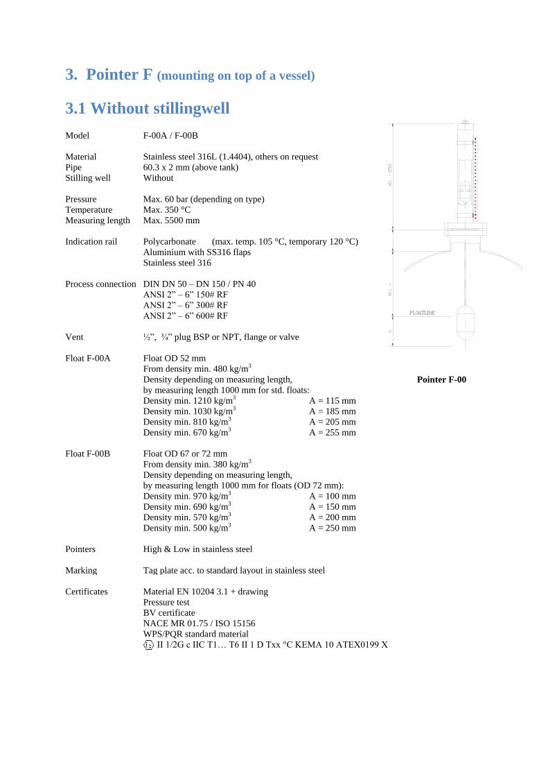
3. Pointer F (mounting on top of a vessel)
3.1 Without stillingwell Model F-00A / F-00B
Pointer F-00
Material Stainless steel 316L (1.4404), others on request
Pipe
Stilling well
60.3 x 2 mm (above tank)
Without
Pressure Max. 60 bar (depending on type)
Temperature Max. 350 °C
Measuring length Max. 5500 mm
Indication rail Polycarbonate (max. temp. 105 °C, temporary 120 °C)
Aluminium with SS316 flaps
Stainless steel 316
Process connection DIN DN 50 – DN 150 / PN 40
ANSI 2” – 6” 150# RF
ANSI 2” – 6” 300# RF
ANSI 2” – 6” 600# RF
Vent ½”, ¾” plug BSP or NPT, flange or valve
Float F-00A Float OD 52 mm
From density min. 480 kg/m3
Density depending on measuring length,
by measuring length 1000 mm for std. floats:
Density min. 1210 kg/m3 A = 115 mm
Density min. 1030 kg/m3 A = 185 mm
Density min. 810 kg/m3 A = 205 mm
Density min. 670 kg/m3 A = 255 mm
Float F-00B Float OD 67 or 72 mm
From density min. 380 kg/m3
Density depending on measuring length,
by measuring length 1000 mm for floats (OD 72 mm):
Density min. 970 kg/m3 A = 100 mm
Density min. 690 kg/m3 A = 150 mm
Density min. 570 kg/m3 A = 200 mm
Density min. 500 kg/m3 A = 250 mm
Pointers High & Low in stainless steel
Marking Tag plate acc. to standard layout in stainless steel
Certificates Material EN 10204 3.1 + drawing
Pressure test
BV certificate
NACE MR 01.75 / ISO 15156
WPS/PQR standard material
II 1/2G c IIC T1… T6 II 1 D Txx °C KEMA 10 ATEX0199 X

3.2 With stilling well pipe 54 or 60.3 Model F-01 / F-01A
Pointer F-01A
Material Stainless steel 316L (1.4404), others on request
Pipe
Stilling well
60.3 x 2 mm (above tank)
pipe 54 or 60.3
Pressure Max. 60 bar (depending on type)
Temperature Max. 350 °C
Measuring length Max. 5500 mm
Indication rail Polycarbonate (max. temp. 105 °C, temporary 120 °C)
Aluminium with SS316 flaps
Stainless steel 316
Process connection DIN DN 50 – DN 150 / PN 40
ANSI 2” – 6” 150# RF
ANSI 2” – 6” 300# RF
ANSI 2” – 6” 600# RF
Vent ½”, ¾” plug BSP or NPT, flange or valve
Float F-01 Stilling well pipe OD 60.3, float OD 52
From density min. 480 kg/m3
Density depending on measuring length,
by measuring length 1000 mm for std. floats:
Density min. 1160 kg/m3 A = 150 mm
Density min. 1030 kg/m3 A = 185 mm
Density min. 810 kg/m3 A = 205 mm
Density min. 670 kg/m3 A = 255 mm
Float F-01A Stilling well pipe OD 54, float OD 47
From density min. 600 kg/m3
Density depending on measuring length,
by measuring length 1000 mm for std. floats:
Density min. 1050 kg/m3 A = 150 mm
Density min. 910 kg/m3 A = 200 mm
Density min. 800 kg/m3 A = 250 mm
Density min. 730 kg/m3 A = 300 mm
Pointers High & Low in stainless steel
Marking Tag plate acc. to standard layout in stainless steel
Certificates Material EN 10204 3.1 + drawing
Pressure test
BV certificate
NACE MR 01.75 / ISO 15156
WPS/PQR standard material
II 1/2G c IIC T1… T6 II 1 D Txx °C KEMA 10 ATEX0199 X

3.3 With 3- rods 76 or 104 Model F-02 / F-04
Pointer F-02
Material Stainless steel 316L (1.4404), others on request
Pipe
Stilling well
60.3 x 2 mm (above tank)
3- rods 76 or 104
Pressure Max. 60 bar (depending on type)
Temperature Max. 350 °C
Measuring length Max. 5500 mm
Indication rail Polycarbonate (max. temp. 105 °C, temporary 120 °C)
Aluminium with SS316 flaps
Stainless steel 316
Process connection DIN DN 80 – DN 150 / PN 40
ANSI 3” – 6” 150# RF
ANSI 3” – 6” 300# RF
ANSI 3” – 6” 600# RF
Vent ½”, ¾” plug BSP or NPT, flange or valve
Float F-02 3- rods 76, float OD 52 mm
From density min. 480 kg/m3
Density depending on measuring length,
by measuring length 1000 mm for std. floats:
Density min. 1160 kg/m3 A = 150 mm
Density min. 1030 kg/m3 A = 185 mm
Density min. 810 kg/m3 A = 205 mm
Density min. 670 kg/m3 A = 255 mm
Float F-04 3- rods 104, float OD 72mm
From density min. 380 kg/m3
Density depending on measuring length,
by measuring length 1000 mm for std. floats:
Density min. 970 kg/m3 A = 100 mm
Density min. 690 kg/m3 A = 150 mm
Density min. 570 kg/m3 A = 200 mm
Density min. 500 kg/m3 A = 250 mm
Pointers High & Low in stainless steel
Marking Tag plate acc. to standard layout in stainless steel
Certificates Material EN 10204 3.1 + drawing
Pressure test
BV certificate
NACE MR 01.75 / ISO 15156
WPS/PQR standard material
II 1/2G c IIC T1… T6 II 1 D Txx °C KEMA 10 ATEX0199 X

3.4 With stilling well pipe 76.1 or 88.9 Model F-03A / F-03B
Pointer F-03
Material Stainless steel 316L (1.4404), others on request
Pipe
Stilling well
60.3 x 2 mm (above tank)
Pipe 76.1 or 88.9
Pressure Max. 20 bar (depending on type)
Temperature Max. 350 °C
Measuring length Max. 5500 mm
Indication rail Polycarbonate (max. temp. 105 °C, temporary 120 °C)
Aluminium with SS316 flaps
Stainless steel 316
Process connection DIN DN 80 – DN 150 / PN 40
ANSI 3” – 6” 150# RF
ANSI 3” – 6” 300# RF
ANSI 3” – 6” 600# RF
Vent ½”, ¾” plug BSP or NPT, flange or valve
Float F-03A Pipe 76.1, float OD 67 mm
From density min. 470 kg/m3
Density depending on measuring length,
by measuring length 1000 mm for std. floats:
Density min. 1050 kg/m3 A = 100 mm
Density min. 760 kg/m3 A = 150 mm
Density min. 630 kg/m3 A = 200 mm
Density min. 560 kg/m3 A = 250 mm
Float F-03B Pipe 88.9, float OD 72
From density min. 380 kg/m3
Density depending on measuring length,
by measuring length 1000 mm for std. floats:
Density min. 970 kg/m3 A = 100 mm
Density min. 690 kg/m3 A = 150 mm
Density min. 570 kg/m3 A = 200 mm
Density min. 500 kg/m3 A = 250 mm
Pointers High & Low in stainless steel
Marking Tag plate acc. to standard layout in stainless steel
Certificates Material EN 10204 3.1 + drawing
Pressure test
BV certificate
NACE MR 01.75 / ISO 15156
WPS/PQR standard material
II 1/2G c IIC T1… T6 II 1 D Txx °C KEMA 10 ATEX0199 X

4. Pointer R (mounting between two pipes) Model R-40 / R-150 / R-300
Material Stainless steel 316L (1.4404)
Pipe 60.3 x 2 mm or 60.3 x 2.77 mm
Pressure Max. 40 bar / 150 or 300 lbs
Temperature Max. 400 °C
C. to C. Till 5500 mm in 1 piece, longer out more pieces
Indication rail Polycarbonate (max. temp. 105 °C, temporary 120 °C)
Aluminium with SS316 flaps
Stainless steel 316
Process connection DIN DN 15 – DN 50 / PN 40
ANSI ½” – 2” 150 - 300# RF
Thread (Male / Female) ½” – 1” BSP or NPT
Float From density min. 380 kg/m3
Extra support C. to C. > 3 meter for offshore
Pointer R
C. to C. > 4 meter for onshore
Pointers High & Low in stainless steel
Marking Tag plate acc. to standard layout in stainless steel
PED marking till cat. III std.
Certificates Material EN 10204 3.1 + drawing
Pressure test
DNV-GL, LRS or BV certificate
NACE MR 01.75 / ISO 15156
WPS/PQR standard material
II 1/2G c IIC T1… T6 II 1 D Txx °C KEMA 10 ATEX0199 X
Special Insulation, steamjacket, spring, electric tracing

5. Available floats
All the magnetic level gauges are fitted with a float. This float is standard in stainless steel, but the
float is also available in Titanium, Hastelloy, PVC-C, PVC-U, PP, PVDF, PE etc. The float must
have enough buoyancy and the magnet must be fitted at the right position inside the float. So it is
always important to select a float which is suitable for the process conditions.
In order to select the correct float the following process conditions are necessary.
- Medium
- Density
- Working pressure
- Operating temperature
The lowest density, for which we can supply a float is 380 kg/m3 but this is depending on the before
mentioned process conditions.
When a fluid is very aggressive we can also coat the float with a suitable lining.
When we have a choice between an open float or a pressurised float we prefer the pressurized float.
Because the open float will eventually sink, condensate will build up inside the open float. For
example our pressurized floats are suitable for 208 bar at 375°C with a density of 650 kg/m3.
The float inside a magnetic level gauge can be fitted with a torriodal (360°) magnet or a magnetic
bar. All our floats are fitted standard with a torriodalmagnet, because a float with a magnetic bar can
loose there guidance/ indication rail by rapid movement inside the level gauge. As a result the
magnetic level gauge will not work properly for a while. Torriodalmagnets are not affected by rapid
movements of the float and can move freely inside the level gauge. This is also why you can place a
level switch at all the sides you want.
6. Switches
When you mount a magnetic switch on the level gauge it is possible to get a signal. With more
switches you can make a pump control (pump on / off) and / or obtain a high / low alarm.
We can supply general purpose switches, switches for hazardous areas, or switches suitable for
marine applications.

6.1 General purpose level switches
Type HLS-15 LMS-Ha2 HLS-Ha1
Function SPDT SPDT SPDT
System Reed switch bi-stabile Reed switch bi-stabile Micro switch
Max. rating 2,5A / 60W / 60VA 0,8A / 60W / 40VA 5A / 100W / 100VA
Voltage 10 – 230 V 10 – 230 V 10 – 230 V
Temp. rating -25 … +95°C -40… + 180°C -50 … +350°C
Lifetime 1 x 10⁹ 1x 10
8 1 x 10
6
Enclosure IP 66 / 67 and IP 68 IP 65 IP 67
Connection 5 meter cable PVC M16 cable gland M16 cable gland
Dimensions 65 x 25 x 15 mm 100 x 75 x 40 mm 95 x 65 x 54 mm
Material Engineered Resin Aluminium housing AlSi housing
Options M20 cable gland
SS 316 housing

6.2 Intrinsic safe level switches (Ex i)
Type HLS-25i HLS-Ha1E
Function SPDT SPDT
System Reed switch bi-stabile Micro switch
Max. rating 250mA / 1.3W 0,5A / 1.3W
Voltage 10 – 30 V 10 – 30 V
Temp. rating -25 … +100°C -50 … +350°C
Lifetime 1 x 10⁹ 1 x 10
6
Enclosure IP 66 / 67 and IP 68 IP 67
Connection 5 meter cable PVC M20 cable gland (blue)
Dimensions 80 x 25 x 20 mm 95 x 65 x 54 mm
Material SS 316 housing AlSi housing
Approval II 1 GD Exia IIC T6 Ga
II 1 GD Exia IIC T85°C IP66/67 Da
Ex i “simple apparatus“
Option M16 cable gland (blue)
SS 316 housing

6.2 Flameproof level switches (Ex d)
Type HLS-25d HLS-HaD
Function SPDT SPDT
System Reed switch bi-stabile Micro switch
Max. rating 2.5A / 60W / 45VA 5A / 100W / 100VA
Voltage 10 – 230 V 10 – 230 V
Temp. rating -25 … +100°C -50 … + 350°C
Temp. amb. -20 … +70°C -40 … + 60°C
Lifetime 1 x 10⁹ 1 x 10
6
Enclosure IP 66 / 67 and IP 68 IP 66 / IP 68
Connection 5 meter cable PVC ¾” NPT or M20x1,5 max 1,5 mm2
Dimensions 90 x 25 x 20 mm 130 x 130 x 90 mm
Material SS 316 housing Aluminium housing
Approval II 2 GD Exd IIC T6 Gb
II 2 GD Ex tb IIIC T85°C Db
II 2 G Ex db IIC T5..T1 Gb
II 2 D Ex tb IIIC T100°C..T350°C Db
Option SS 316 Housing
2x SPDT

7. Reedchain for an analog output signal
By using a reedchain it is possible to become a 4-20 mA signal. The reedchain is standard mounted
on the complete length of the magnetic level gauge.
Design Standard Ex i Ex d
Transmitter “SMART” type “SMART” type “SMART” type
Approval II 1G Ex ia II C T4..T6 II 2G Ex db IIC T5..T1 Gb
II 2D Ex tb T100°C..T350°C
Supply 8 – 35 VDC 8 – 30 VDC 8 – 30 VDC
Temperature -50 … +350°C -50 … +350°C -50 … +350°C
Accuracy 5 mm 5 mm 5 mm
Material pipe SS 316 L SS 316 L SS 316 L
Max. length 5,5 meter 5,5 meter 5,5 meter
Material housing Aluminium or SS Aluminium or SS Aluminium or SS316
Enclosure IP 67 IP 67 IP 66 / 67 and IP 68
Connection M16 x 1,5 M20 x 1,5 ¾” NPT, M20x1.5
Output 4 – 20 mA / 2 wire 4 – 20 mA / 2 wire 4 – 20 mA / 2 wire
Action Reversible std. D.A. Reversible std. D.A. Reversible std. D.A.
Options High accuracy ( 2.5 or 1 mm)
M16x1,5; M20x1,5; ½” NPT; ¾” NPT connections
Enclosure IP 68
HART
PROFIBUS
FIELDBUS
SS 316 housing
Housing with LCD display (also optical)
Output signal (Ohm or V)

8. Certificates
We can supply the following certificates with our magnetic level gauges.
- Material EN 10204 3.1 + drawing
- Pressuretest
- DNV-GL, LRS and BV certificate
- ATEX, IECEx certificate
- NACE MR 01-75 / ISO 15156
- X-ray and Dye penetrant
- WPS, PQR welding protocol
- And others on request

9. Application form
For an offer, please fill out this form and email to [email protected]
Company : ………………………………………………………………………………
Contact person : ………………………………………………………………………………
Address : ………………………………………………………………………………
Postcode : …………………………... City : ………………………….………...
Country : ………………………………………………………………………………
Telephone : ………………………………………………………………………………
E-mail : ………………………………………………………………………………
Space for your remarks: Type : D L F M R
Tag Nr. : ……………………………………...
Quantity : ……………………………………...
Measuring length : C. to C. ………………………....mm
PROCESS CONDITIONS Medium : ……………………………….……...
Density (kg/m3) : ….... min ……... max ….....
Pressure : ….... min ……... max ….....
Temperature : ….... min ……... max ….....
Viscosity : < 80 cst or ………………….……cst
DESIGN Flanged Couplings
Thread Butt-weld
Material : SS 316L or ………………………….
Connection size : ………………………………….…...
Pressure rating : ……….. Sealing surface ….……...
Drain (bottom/side) : G..……/…..…NPT / flange ………..
Vent : Closed, G…/... NPT / flange ……....
Gasket material : Std. / SS spiral wound / graphite / .....
CERTIFICATES OPTIONS Ship approvals : DNV-GL /
Float malfunction : Yes / No optical indication
LRS / BV Switches : …. STD / Exi / Exd
Material cert. : EN 10204 3.1 Scale / ruler : cm / mm / 0-100% / acc. tank content
Welding proc. : WPS / PQR Level transmitter : 4-20 mA / Exi / Exd / HART
X-ray : NO / 10 / 100% Frost protection : Yes / No electric, steam, oil
Explosion : ATEX / IECEx Insulation : Cold / Heat resistant
Pressure test : HADRO / …......