magnetic starters (ge) - 30a, 120, 240 and 575 volt coils
TRANSCRIPT

Manual No: 577014-045 ● Revision: B
Wiring Guide
Magnetic Starters (GE) - 30A, 120, 240and 575 Volt Coils

ii
Notice
Veeder-Root makes no warranty of any kind with regard to this publication, including, but not limited to, the implied warranties ofmerchantability and fitness for a particular purpose.
Veeder-Root shall not be liable for errors contained herein or for incidental or consequential damages in connectionwith the furnishing, performance, or use of this publication.
Veeder-Root reserves the right to change system options or features, or the information contained in this publication.
This publication contains proprietary information which is protected by copyright. All rights reserved. No part of this publication may bephotocopied, reproduced, or translated to another language without the prior written consent of Veeder-Root.
Contact Red Jacket Technical Support for additional troubleshooting information at 800-323-1799.
DAMAGE GOODS/LOST EQUIPMENT
Thoroughly examine all components and units as soon as they are received. If any cartons are damaged or missing, write a completeand detailed description of the damage or shortage on the face of the freight bill. The carrier's agent must verify the inspection and signthe description. Refuse only the damaged product, not the entire shipment.
VR must be notified of any damages and/or shortages within 30 days of receipt of the shipment, as stated in our Terms and Conditions.
VEEDER-ROOT’S PREFERRED CARRIER
1. Fax Bill of Lading to V/R Customer Service at 800-234-5350.
2. Call V/R Customer Service at 800-873-3313 with the specific part numbers and quantities that were received damaged or lost.
3. VR will file the claim with the carrier and replace the damaged/missing product at no charge to the customer. Customer Servicewill work with production facility to have the replacement product shipped as soon as possible.
CUSTOMER’S PREFERRED CARRIER
1. Customer files claim with carrier.
2. Customer may submit a replacement purchase order. Customer Service will work with production facility to have the replacementproduct shipped as soon as possible.
3. If “lost” equipment is delivered at a later date and is not needed, VR will allow a Return to Stock without a restocking fee.
4. VR will NOT be responsible for any compensation when a customer chooses their own carrier.
RETURN SHIPPING
For the parts return procedure, please follow the instructions in the “General Returned Goods Policy” pages of the “Policies andLiterature” section of the Veeder-Root North American Red Jacket Mechanical Products Price Book. Veeder-Root will not accept anyreturn product without a Return Goods Authorization (RGA) number clearly printed on the outside of the package.
©Veeder-Root 2018. All rights reserved.

Table of Contents
iii
Introduction Related Manuals ...............................................................................................................1Safety Precautions ............................................................................................................1
Installation Troubleshooting ................................................................................................................3Configuring The Magnetic Starter .....................................................................................3Wiring Diagrams ...............................................................................................................5
FiguresFigure 1. Wiring Diagram For 208/240 Volt Maxxum Pump With 120 Volt Coil
And 120 Volt Isotrol ................................................................................5Figure 2. Wiring Diagram For 575 Volt Maxxum Pump With 120 Volt Coil
And 120 Volt Isotrol ................................................................................6Figure 3. Wiring Diagram For 208-230/460 Volt 5HP RJ DEF Pump
(Low Voltage) With 120 Volt Coil And 120 Volt Isotrol ............................7Figure 4. Wiring Diagram For 208-230/460 Volt 5HP RJ DEF Pump
(High Voltage) With 120 Volt Coil And 120 Volt Isotrol ...........................8Figure 5. Wiring Diagram For 575 Volt 5HP RJ DEF Pump
(Single Voltage) With 120 Volt Coil And 120 Volt Isotrol ........................9Figure 6. Wiring Diagram For 208/230 Volt CoreDEF Pump With
120 Volt Coil And 120 Volt Isotrol .........................................................10Figure 7. Wiring Diagram For 208/240 Volt Maxxum Pump With 120 Volt Coi .......11Figure 8. Wiring Diagram For 208/230 Volt CoreDEF Pump With 120 Volt Coil .....12Figure 9. Wiring Diagram For 380/415 Volt Maxxum Pump With
240 Volt Coil And 240 Volt Isotrol .........................................................13Figure 10. Wiring Diagram For 380/415 Volt CoreDEF Pump With
240 Volt Coil And 240 Volt Isotrol .........................................................14Figure 11. Wiring Diagram For 380/415 Volt TRJ Or Standard Pump
With 240 Volt Coil And 240 Volt Isotrol .................................................15Figure 12. Wiring Diagram For 208/240 Volt Maxxum Pump With 240 Volt Coil ......16Figure 13. Wiring Diagram For 380/415 Volt Maxxum Pump With 240 Volt Coil ......17Figure 14. Wiring Diagram For 208/230 Volt CoreDEF Pump With 240 Volt Coil .....18Figure 15. Wiring Diagram For 380/415 Volt Core DEF Pump With 240 Volt Coil ....19Figure 16. Wiring Diagram For 380/415 VoIt TRJ Or Standard Pump
With 240 Volt Coil .................................................................................20Figure 17. Wiring Diagram For 575 Volt Maxxum Pump With 575 Volt Coil ..........21
TablesTable 1. V-R Magnetic Starters ...............................................................................3Table 2. V-R Pump Heaters And Wiring Diagrams .................................................3

1
Introduction
Magnetic Starters covered in this manual are 30A, 3 phase, full voltage across the line starters with the coil factory wired for 110–120 volts, 208–240 volts or 575-600 volts dependent upon the device (see Table 1 on page 3). Check with the local power company to see if their power source is adequate for your requirements. Wiring diagrams are provided to show typical wiring schemes depending upon the pump model and coil voltage rating.
These devices require the installation of 3-leg ambient compensated overload heaters for proper operation and for motor protection. Please refer to Table 2 on page 3 for proper selection of the heaters which are purchased separately. Overload relays contain ±10% trip adjustment – achieved by turning a dial in the overload relay face to ‘tune’ the protection to the motor on the spot.
The enclosure is rated NEMA 1 and is to be installed only in a non-hazardous indoorlocation. Use 75°C copper conductors only. Torque terminals to 20 Lb-in.
Related Manuals
577013-830 The Red Jacket Submersible Turbine Pump Install, Service & Parts
D042-153 4” Submersible Petroleum and AG Pump Install, Operate and Service
577014-089 Maxxum Big-Flo 6” Submersible Pump Install, Operate & Service - FM Motor
577014-062 The Red Jacket DEF Pump Installatiion Manual
577014-360 CoreDEF Series Submersible DEF Pump
D051-329 Isotrol 1-8 Control Box Installation and Owner’s Manual
Safety Precautions
The following safety symbols are used throughout this manual to alert you to important safety hazards and precautions.
EXPLOSIVEFuels and their vapors are extremely explosive if ignited.
FLAMMABLEFuels and their vapors are extremely flammable.
ELECTRICITYHigh voltage exists in, and is supplied to, the device. A potential shock hazard exists.
TURN POWER OFFLive power to a device creates a potential shock haz-ard. Turn Off power to the device and associated accessories when servicing the unit.
WARNING indicates a hazardous situation which, if not avoided, could result in death or seri-ous injury.
READ ALL RELATED MANUALSKnowledge of all related procedures before you begin work is important. Read and understand all manuals thoroughly. If you do not understand a procedure, ask someone who does.
WARNING
OFF
WARNING

Introduction Safety Precautions
2
WARNINGThis magnetic starter is to be installed with systems operating near locations where highly combustible fuels or vapors may be present. FAILURE TO COMPLY WITH THE FOLLOWING WARNINGS AND SAFETY PRECAUTIONS COULD CAUSE DAMAGE TO PROPERTY, ENVIRONMENT, RESULTING IN SERIOUS INJURY OR DEATH.Read and follow all instructions in this manual, including all safety warnings.Comply with all applicable codes including the National Electrical Code (NFPA70); Code for Motor Fuel Dispensing Facilities and Repair Garages (NFPA 30A); federal, state, and local codes; and other applicable safety codes.
This magnetic starter contains high voltages which can be lethal. Do not connect the Magnetic Starter AC power supply wires at the breaker until all devices are installed. Connecting power wires to a live circuit can cause electrical shock that may result in serious injury or death.These starters are designed to be used with copper wire - DO NOT USE ALUMINUM WIRE!
Explosive vapors or flammable liquids could be present near locations where fuels are stored or being dispensed.The Magnetic Starter is not explosion proof. Do not install this device in a volatile, combustible, or explosive atmosphere.An explosion or fire resulting in serious injury or death, property loss and equipment damage could occur if the Magnetic Starter is installed in a volatile, combustible, or explosive atmosphere (Class I, Division 1 or 2).
OFF

3
Installation
Troubleshooting
WARNING! Lockout and tag power before performing either of these two procedures.
1. If nuisance tripping occurs, check for proper heaters, loose connections, and severe arcing or pitting of contacts.
Overload adjustments should be set no higher than 100% unless necessary to stop nuisance tripping with measured amperage in all lines below maximum pump nameplate value.
2. If the pump rotates backwards as evidenced by low pressure and flow, correct rotation by reversing any two of the three power wires to the pump.
Configuring The Magnetic Starter
Table 1 and Table 2 are used to determine the proper Magnetic Starter, Heaters and Wiring Diagram for the application.
Table 1. V-R Magnetic Starters
V-R Part No. Description
410648-001 GE Magnetic starter 120V coil CR306C10200AAAAA
410648-002 GE Magnetic starter 240V coil CR306C10300AAAAA
410648-003 GE Magnetic starter 575V coil CR306C10400AAAAA
Table 2. V-R Pump Heaters And Wiring Diagrams
Pump V-R Pump Model V-R Heater No.GE Amb. Comp. Heater(Quantity of 3 Required)
Use These WiringDiagrams
TRJ or Standard
P75U17-3, AGP75S17-3 410649-001 CR123C268A Trip Amps 2.59 ±10%Figure 11 or Figure 16
P150U17-3, AGP150S17-3410649-002 CR123C379A Trip Amps 4.20 ±10% Figure 11 or
Figure 16X4P150U17, X4AGP150S17
P200U17-4, AGP200S17-4 410649-003 CR123C526A Trip Amps 5.63 ±10% Figure 11 or Figure 16
OFF

Installation Configuring The Magnetic Starter
4
Maxxum
P200J4-2MB 410649-004 CR123C778A Trip Amps 8.18 ±10% Figure 1 or Figure 7 or Figure 12
P300J17-3HB 410649-005 CR123C592A Trip Amps 6.24 ±10% Figure 9 or Figure 13
P300J4-2HB 410649-006 CR123C113B Trip Amps 11.8 ±10% Figure 1 or Figure 7 or Figure 12
P500J17-3K 410649-007 CR123C955A Trip Amps 9.91 ±10% Figure 9 or Figure 13
P500J4-2K 410649-008 CR123C180B Trip Amps 19.4 ±10% Figure 1 or Figure 7 or Figure 12
P500J6-2K 410649-009 CR123C695A Trip Amps 7.35 ±10% Figure 2 or Figure 17
DEF
RJ DEF PUMP 5HP 575V 410649-003 CR123C526A Trip Amps 5.63 ±10% Figure 5
RJ DEF PUMP 5HP 460V 410649-009 CR123C695A Trip Amps 7.35 ±10% Figure 4
RJ DEF PUMP 5HP 208/240V 410649-011 CR123C137B Trip Amps 14.1 ±10% Figure 3
CoreDEF Series DP200U17 410649-003 CR123C526A Trip Amps 5.63 ±10% Figure 10 or Figure 15
CoreDEF Series DP200U4 410649-010 CR123C867A Trip Amps 9.34±10% Figure 6 or Figure 8 or Figure 14
Table 2. V-R Pump Heaters And Wiring Diagrams
Pump V-R Pump Model V-R Heater No.GE Amb. Comp. Heater(Quantity of 3 Required)
Use These WiringDiagrams

Installation Wiring Diagrams
5
Wiring Diagrams
Figure 1. Wiring Diagram For 208/240 Volt Maxxum Pump With 120 Volt Coil And 120 Volt Isotrol
Orange
Red
BlackBlue
Blue
T1
L1
L1 L2N L3
L2
L3
T2 T3
To 208/240V Supply
120 VIsotrol
120 V Coil
3 AmbientCompensatedHeaters
COIL
2
9
3
To STP
TB1
ATG
5-Wire electricalinterlock
Thermaloverloadprotector
Extractablepacker
Junction box in manifold
MotorSTP
RED
BLKORG
BLUBLUGRN
LEGEND
Overloadheater
Normallyclosedcontact
Normallyopen
contact
Screwterminal
Wire addedby installer
Wire addedby manufacturer
045-1
or
DISCONNECT, LOCK OUT, AND TAG POWER AT THE POWER PANEL BEFORE WIRING THE PUMP.
WARNINGOFF
Starter is wired for 208/240 V to pump motor, 120 V from Isotrol or dispenser switch. Remove red wire connecting 9 to L2.
NOTICE
Connect ToElectricalGround
Make ground connection inaccordance with local codes.
NOTICE

Installation Wiring Diagrams
6
Figure 2. Wiring Diagram For 575 Volt Maxxum Pump With 120 Volt Coil And 120 Volt Isotrol
Orange
Red
BlackBlue
Blue
T1
L1
L1 L2N L3
L2
L3
T2 T3
To 575 V Supply120 V Supply
120 VIsotrol
120 V Coil
3 AmbientCompensatedHeaters
COIL
2
9
3
To STP
NOTE: Starter is wiredfor 575 V to pump motor,120 V from Isotrol or dispenser switch. Remove red wire connecting 9 to L2.
Make ground connection in accordance with local codes.
TB1
ATG
5-Wire electricalinterlock
Thermaloverloadprotector
Extractablepacker
Junction box in manifold
MotorSTP
RED
BLKORG
BLUBLUGRN
LEGEND
Overloadheater
Normallyclosedcontact
Normallyopen
contact
Screwterminal
Wire addedby installer
Wire addedby manufacturer 045-2
or
DISCONNECT, LOCK OUT, AND TAG POWER AT THE POWER PANEL BEFORE WIRING THE PUMP.
WARNINGOFF
Connect ToElectricalGround
Make ground connection inaccordance with local codes.
NOTICE

Installation Wiring Diagrams
7
Figure 3. Wiring Diagram For 208-230/460 Volt 5HP RJ DEF Pump (Low Voltage) With 120 Volt Coil And 120 Volt Isotrol
T1
L1
L1 L2N
J J L1 L2 L3
L3
L2
L3
T2 T3
To 208/240V Supply
120 VIsotrol
120 V Coil
3 AmbientCompensatedHeaters
COIL
2
9
3
To RJ DEF PUMP
Seal-off, epoxyseal per NFPA specifications
TB1
ATG
LEGEND
Overloadheater
Normallyclosedcontact
Normallyopen
contact
Screwterminal
Wire addedby installer
Wire addedby manufacturer
045-3
oror
LOW VOLTAGE
LINE
6 5 4
9 8 7
3 2 1J J
L3 L2 L1 J J
T’STATLEADS
Motor
Connect ToElectricalGround
DISCONNECT, LOCK OUT, AND TAG POWER AT THE POWER PANEL BEFORE WIRING THE PUMP.
WARNINGOFF
Make ground connection inaccordance with local codes.
NOTICE
Starter is wired for 208/240 V to pump motor, 120 V from Isotrol or dispenser switch. Remove red wire connecting 9 to L2.
NOTICE

Installation Wiring Diagrams
8
Figure 4. Wiring Diagram For 208-230/460 Volt 5HP RJ DEF Pump (High Voltage) With 120 Volt Coil And 120 Volt Isotrol
T1
L1
L1 L2N
J J L1 L2 L3
L3
L2
L3
T2 T3
To 460V Supply120V Supply
120 VIsotrol
120 V Coil
3 AmbientCompensatedHeaters
COIL
2
9
3
To RJ DEF PUMP
Seal-off, epoxyseal per NFPA specifications
TB1
ATG
045-4
HIGH VOLTAGE
LINE
6 5 4
9 8 7
3 2 1J J
L3 L2 L1 J J
T’STATLEADS
Motor
Connect ToElectricalGround
DISCONNECT, LOCK OUT, AND TAG POWER AT THE POWER PANEL BEFORE WIRING THE PUMP.
WARNINGOFF
LEGEND
Overloadheater
Normallyclosedcontact
Normallyopen
contact
Screwterminal
Wire addedby installer
Wire addedby manufacturer
oror
Make ground connection inaccordance with local codes.
NOTICE
Starter is wired for 460 V to pump motor, 120 V from Isotrol or dispenser switch. Remove red wire connecting 9 to L2.
NOTICE

Installation Wiring Diagrams
9
Figure 5. Wiring Diagram For 575 Volt 5HP RJ DEF Pump (Single Voltage) With 120 Volt Coil And 120 Volt Isotrol
T1
L1
L1 L2N
J J L1 L2 L3
L3
L2
L3
T2 T3
To 575V Supply120V Supply
120 VIsotrol
120 V Coil
3 AmbientCompensatedHeaters
COIL
2
9
3
To RJ DEF PUMP
Seal-off, epoxyseal per NFPA specifications
TB1
ATG
045-5
SINGLE VOLT MOTORS
LINE
3 2 1J J
L3 L2 L1 J J
T’STATLEADS
Motor
Connect ToElectricalGround
DISCONNECT, LOCK OUT, AND TAG POWER AT THE POWER PANEL BEFORE WIRING THE PUMP.
WARNINGOFF
Make ground connection inaccordance with local codes.
NOTICE
Starter is wired for 575 V to pump motor, 120 V from Isotrol or dispenser switch. Remove red wire connecting 9 to L2.
NOTICE
LEGEND
Overloadheater
Normallyclosedcontact
Normallyopen
contact
Screwterminal
Wire addedby installer
Wire addedby manufacturer
oror

Installation Wiring Diagrams
10
Figure 6. Wiring Diagram For 208/230 Volt CoreDEF Pump With 120 Volt Coil And 120 Volt Isotrol
T1
L1
L1 L2N
L1 L2 L3
L3
L2
L3
T2 T3
Brown Grey Black
To 208/230V Supply
120 VIsotrol
120 V Coil
3 AmbientCompensatedHeaters
COIL
2
9
3
To UMP
TB1
ATG
045-6
Connect ToElectricalGround
DISCONNECT, LOCK OUT, AND TAG POWER AT THE POWER PANEL BEFORE WIRING THE PUMP.
WARNINGOFF
Cable strainrelief
SubmersibleDEF pump
Liquid-Tightjunction box
Motor
BrownBlack
Green
Grey
LEGEND
Overloadheater
Normallyclosedcontact
Normallyopen
contact
Screwterminal
Wire addedby installer
Wire addedby manufacturer
oror
Make ground connection inaccordance with local codes.
NOTICE
Starter is wired for 208/240 V to pump motor, 120 V from Isotrol or dispenser switch. Remove red wire connecting 9 to L2.
NOTICE

Installation Wiring Diagrams
11
Figure 7. Wiring Diagram For 208/240 Volt Maxxum Pump With 120 Volt Coi
Orange RedBlack
T1
L1
L1 L2N L3
L2
L3
T2 T3
To 208/240 V Supply
120 V Coil
COIL
2
9
3
To STP
5-Wire electricalinterlock
Thermaloverloadprotector
Extractablepacker
Junction box in manifold
MotorSTP
RED
BLKORG
BLUBLUGRN
LEGEND
Overloadheater
Normallyclosedcontact
Normallyopen
contact
Screwterminal
Wire addedby installer
Wire addedby manufacturer
045-7
Blue
Blue
Dispenser
or
DISCONNECT, LOCK OUT, AND TAG POWER AT THE POWER PANEL BEFORE WIRING THE PUMP.
WARNINGOFF
3 AmbientCompensatedHeaters
Connect ToElectricalGround
Make ground connection inaccordance with local codes.
NOTICE
Starter is wired for 208/240 V to pump motor, 120 V to dispenser switch.
NOTICE

Installation Wiring Diagrams
12
Figure 8. Wiring Diagram For 208/230 Volt CoreDEF Pump With 120 Volt Coil
T1
L1
L1 L2N L3
L2
L3
T2 T3
To 208/230 V Supply
120 V Coil
COIL
2
9
3
045-8
Dispenser
DISCONNECT, LOCK OUT, AND TAG POWER AT THE POWER PANEL BEFORE WIRING THE PUMP.
WARNINGOFF
3 AmbientCompensatedHeaters
Connect ToElectricalGround
Brown Grey Black
To UMP
Cable strainrelief
SubmersibleDEF pump
Liquid-Tightjunction box
Motor
BrownBlack
Green
Grey
LEGEND
Overloadheater
Normallyclosedcontact
Normallyopen
contact
Screwterminal
Wire addedby installer
Wire addedby manufacturer
ororMake ground connection inaccordance with local codes.
NOTICE
Starter is wired for 208/240 V to pump motor, 120 V to dispenser switch.
NOTICE
Installation Wiring Diagrams
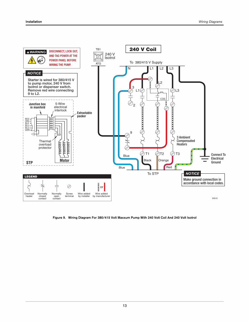
13
Figure 9. Wiring Diagram For 380/415 Volt Maxxum Pump With 240 Volt Coil And 240 Volt Isotrol
Orange
Red
BlackBlue
Blue
T1
L1
L1 L2N L3
L2
L3
T2 T3
To 380/415 V Supply
240 VIsotrol
240 V Coil
COIL
2
9
3
To STP
TB1
ATG
5-Wire electricalinterlock
Thermaloverloadprotector
Extractablepacker
Junction box in manifold
MotorSTP
RED
BLKORG
BLUBLUGRN
LEGEND
Overloadheater
Normallyclosedcontact
Normallyopen
contact
Screwterminal
Wire addedby installer
Wire addedby manufacturer
045-9
or
3 AmbientCompensatedHeaters
Connect ToElectricalGround
DISCONNECT, LOCK OUT, AND TAG POWER AT THE POWER PANEL BEFORE WIRING THE PUMP.
WARNINGOFF
Make ground connection inaccordance with local codes.
NOTICE
Starter is wired for 380/415 V to pump motor, 240 V from Isotrol or dispenser switch. Remove red wire connecting 9 to L2.
NOTICE
Installation Wiring Diagrams
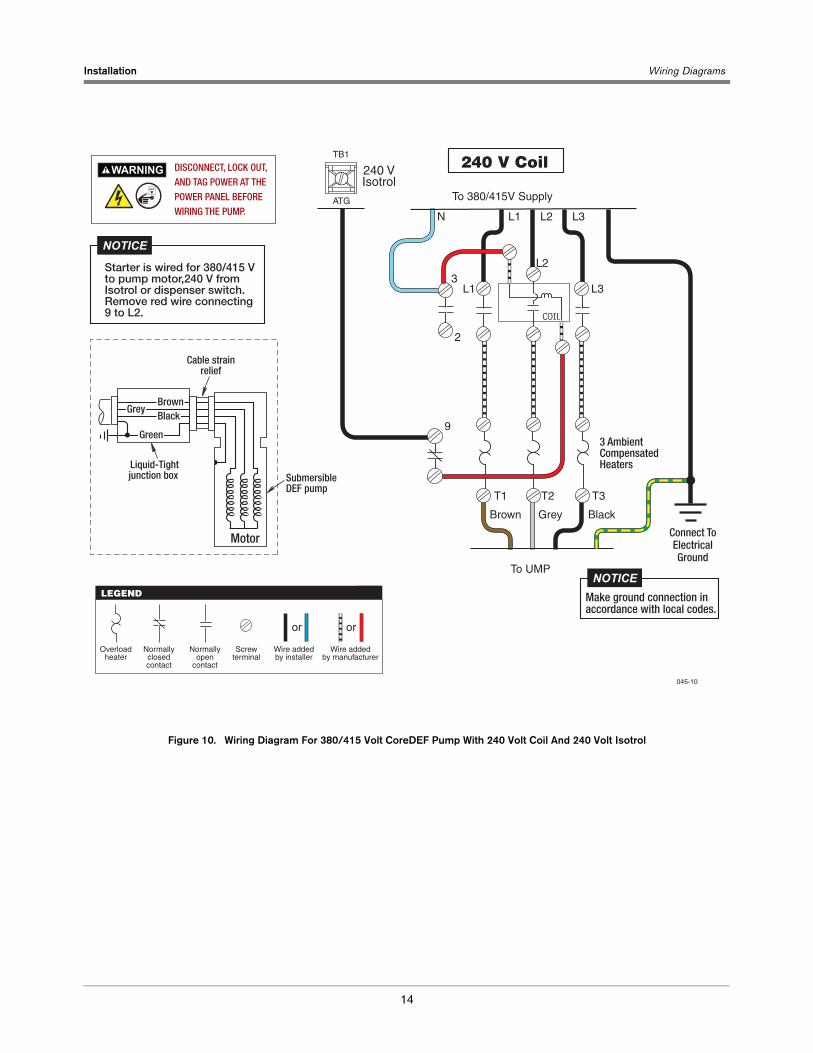
14
Figure 10. Wiring Diagram For 380/415 Volt CoreDEF Pump With 240 Volt Coil And 240 Volt Isotrol
T1
L1
L1 L2N L3
L2
L3
T2 T3
Brown Grey Black
To 380/415V Supply
240 VIsotrol
240 V Coil
3 AmbientCompensatedHeaters
COIL
2
9
3
To UMP
TB1
ATG
045-10
Connect ToElectricalGround
DISCONNECT, LOCK OUT, AND TAG POWER AT THE POWER PANEL BEFORE WIRING THE PUMP.
WARNINGOFF
Cable strainrelief
SubmersibleDEF pump
Liquid-Tightjunction box
Motor
BrownBlack
Green
Grey
LEGEND
Overloadheater
Normallyclosedcontact
Normallyopen
contact
Screwterminal
Wire addedby installer
Wire addedby manufacturer
oror
Make ground connection inaccordance with local codes.
NOTICE
Starter is wired for 380/415 V to pump motor,240 V from Isotrol or dispenser switch. Remove red wire connecting 9 to L2.
NOTICE

Installation Wiring Diagrams
15
Figure 11. Wiring Diagram For 380/415 Volt TRJ Or Standard Pump With 240 Volt Coil And 240 Volt Isotrol
T1
L1
L1 L2N L3
L2
L3
T2 T3
Orange Black Red
To 380/415V Supply
240 VIsotrol
240 V Coil
3 AmbientCompensatedHeaters
COIL
2
9
3
To STP
TB1
ATG
LEGEND
Overloadheater
Normallyclosedcontact
Normallyopen
contact
Screwterminal
Wire addedby installer
Wire addedby manufacturer
045-11
or
Connect ToElectricalGround
DISCONNECT, LOCK OUT, AND TAG POWER AT THE POWER PANEL BEFORE WIRING THE PUMP.
WARNINGOFF
Electricalinterlock
On-windingoverload
protectors
Extractablepacker
Junction box in manifold
MotorSTP
R
OG
Make ground connection inaccordance with local codes.
NOTICE
Starter is wired for 380/415 V to pump motor, 240 V from Isotrol or dispenser switch. Remove red wire connecting 9 to L2.
NOTICE

Installation Wiring Diagrams
16
Figure 12. Wiring Diagram For 208/240 Volt Maxxum Pump With 240 Volt Coil
To 208/240 V Supply
240 V Coil
To STP
5-Wire electricalinterlock
Thermaloverloadprotector
Extractablepacker
Junction box in manifold
MotorSTP
RED
BLKORG
BLUBLUGRN
LEGEND
Overloadheater
Normallyclosedcontact
Normallyopen
contact
Screwterminal
Wire addedby installer
Wire addedby manufacturer
045-12
or
Connect ToElectricalGround
DISCONNECT, LOCK OUT, AND TAG POWER AT THE POWER PANEL BEFORE WIRING THE PUMP.
WARNINGOFF
Make ground connection inaccordance with local codes.
NOTICE
Starter is wired for 208/240 V to pump motor, 208/240 V to dispenser switch.
NOTICE
Orange RedBlack
T1
L1
L1 L2 L3
L2
L3
T2 T3
3 AmbientCompensatedHeaters
COIL
2
9
3
Blue
Blue
Dispenser

Installation Wiring Diagrams
17
Figure 13. Wiring Diagram For 380/415 Volt Maxxum Pump With 240 Volt Coil
Orange RedBlack
T1
L1
L1 L2N L3
L2
L3
T2 T3
To 380/415 V Supply
240 V Coil
3 AmbientCompensatedHeaters
COIL
2
9
3
To STP
5-Wire electricalinterlock
Thermaloverloadprotector
Extractablepacker
Junction box in manifold
MotorSTP
RED
BLKORG
BLUBLUGRN
LEGEND
Overloadheater
Normallyclosedcontact
Normallyopen
contact
Screwterminal
Wire addedby installer
Wire addedby manufacturer 045-13
Blue
Blue
Dispenser
orMake ground connection in accordance with local codes.
Connect ToElectricalGround
DISCONNECT, LOCK OUT, AND TAG POWER AT THE POWER PANEL BEFORE WIRING THE PUMP.
WARNINGOFF
Starter is wired for 380/415 V to pump motor, 240V to dispenser switch.
NOTICE

Installation Wiring Diagrams
18
Figure 14. Wiring Diagram For 208/230 Volt CoreDEF Pump With 240 Volt Coil
T1
L1
L1 L2 L3
L2
L3
T2 T3
To 208/230 V Supply
240 V Coil
COIL
2
9
3
LEGEND
Overloadheater
Normallyclosedcontact
Normallyopen
contact
Screwterminal
Wire addedby installer
Wire addedby manufacturer
045-14
Dispenser
oror
DISCONNECT, LOCK OUT, AND TAG POWER AT THE POWER PANEL BEFORE WIRING THE PUMP.
WARNINGOFF
3 AmbientCompensatedHeaters
Connect ToElectricalGround
Brown Grey Black
To UMP
Cable strainrelief
SubmersibleDEF pump
Liquid-Tightjunction box
Motor
BrownBlack
Green
Grey
Make ground connection inaccordance with local codes.
NOTICE
Starter is wired for 208/240 V to pump motor, 208/240 V to dispenser switch.
NOTICE

Installation Wiring Diagrams
19
Figure 15. Wiring Diagram For 380/415 Volt Core DEF Pump With 240 Volt Coil
T1
L1
L1 L2N L3
L2
L3
T2 T3
To 380/415 V Supply
240 V Coil
COIL
2
9
3
045-15
Dispenser
DISCONNECT, LOCK OUT, AND TAG POWER AT THE POWER PANEL BEFORE WIRING THE PUMP.
WARNINGOFF
3 AmbientCompensatedHeaters
Connect ToElectricalGround
Brown Grey Black
To UMP
Cable strainrelief
SubmersibleDEF pump
Liquid-Tightjunction box
Motor
BrownBlack
Green
Grey
LEGEND
Overloadheater
Normallyclosedcontact
Normallyopen
contact
Screwterminal
Wire addedby installer
Wire addedby manufacturer
oror
Make ground connection inaccordance with local codes.
NOTICE
Starter is wired for 380/415 V to pump motor, 240 V to dispenser switch.
NOTICE

Installation Wiring Diagrams
20
Figure 16. Wiring Diagram For 380/415 VoIt TRJ Or Standard Pump With 240 Volt Coil
T1
L1
L1 L2N L3
L2
L3
T2 T3
To 380/415 V Supply
240 V Coil
COIL
2
9
3
LEGEND
Overloadheater
Normallyclosedcontact
Normallyopen
contact
Screwterminal
Wire addedby installer
Wire addedby manufacturer
045-16
Dispenser
or
DISCONNECT, LOCK OUT, AND TAG POWER AT THE POWER PANEL BEFORE WIRING THE PUMP.
WARNINGOFF
3 AmbientCompensatedHeaters
Connect ToElectricalGround
Orange Black Red
To STP Make ground connection inaccordance with local codes.
NOTICE
Starter is wired for 380/415 V to pump motor, 240 V to dispenser switch.
NOTICE
Electricalinterlock
On-windingoverload
protectors
Extractablepacker
Junction box in manifold
MotorSTP
R
OG

Installation Wiring Diagrams
21
Figure 17. Wiring Diagram For 575 Volt Maxxum Pump With 575 Volt Coil
Orange RedBlack
T1
L1
L1 L2 L3
L2
L3
T2 T3
To 575 V Supply
575 V Coil
3 AmbientCompensatedHeaters
COIL
2
9
3
To STP
5-Wire electricalinterlock
Thermaloverloadprotector
Extractablepacker
Junction box in manifold
MotorSTP
RED
BLKORG
BLUBLUGRN
LEGEND
Overloadheater
Normallyclosedcontact
Normallyopen
contact
Screwterminal
Wire addedby installer
Wire addedby manufacturer
045-17
Blue
Blue
Dispenser
or
Connect ToElectricalGround
DISCONNECT, LOCK OUT, AND TAG POWER AT THE POWER PANEL BEFORE WIRING THE PUMP.
WARNINGOFF
Make ground connection inaccordance with local codes.
NOTICE
Starter is wired for 575 V to pump motor, 575 V to dispenser switch.
NOTICE

For technical support, sales orother assistance, please visit:
www.veeder.com