magnetic vertical axis wind turbine · 2.1 rotor axis orientation vertical axis wind turbines...
TRANSCRIPT

International Research Journal of Engineering and Technology (IRJET) e-ISSN: 2395 -0056
Volume: 04 Issue: 05 | May -2017 www.irjet.net p-ISSN: 2395-0072
© 2017, IRJET | Impact Factor value: 5.181 | ISO 9001:2008 Certified Journal | Page 2543
Magnetic Vertical Axis Wind Turbine
Shubham Patil1, Pratik Kumbhar2, Oslaniya Siddharth3, Patil Rohit4, C.S.Wagle5
1,2,3,4Student, Department Of Mechanical Engineering 5Professor, Department Of Mechanical Engineering
1.2.3.4.5Dr.D.Y.Patil Institute Of Technology, Pimpri, Pune, Maharashtra, India
---------------------------------------------------------------------***---------------------------------------------------------------------Abstract - In the recent year, the significance of wind generation is found to be multifold due to huge demand and supply gap in electrical energy system. Maglev wind turbines have several advantages over conventional wind turbines. For instance, they’re able to use winds with starting speeds as low as 1.5 meters per second (m/s) because of negligible friction achieved with the help of magnetic levitation created and due to the assistance from magnetic field. Also, they could operate in winds exceeding 40 m/s. Hence maglev wind turbine has a great future potential in terms of energy generation.
In this respect the current project work would like to address certain design issues and proposes to design , fabricate and test a prototype of magnetically levitated vertical axis wind turbine providing stated advantages, the prototype will be fabricated and tested for the outcome. Key Words: Magnetic levitation, CFD, Magnetic centring, Vertical Axis Wind Turbine, Neodymium magnets.
1. INTRODUCTION The wind turbine is used for conversion of kinetic energy of wind into electrical energy. The wind turns the blades, which spin a shaft, which connects to a generator and makes electricity. The Maglev wind turbine design is a vast departure from conventional propeller designs. Its main advantages are that it uses frictionless bearings and a magnetic levitation design and it does not need to vast spaces required by more conventional wind turbines. It also requires little if any maintenance. The unique operating principle behind this design is through magnetic levitation. Magnetic levitation is supposedly an extremely efficient system for wind energy. The vertically oriented blades of the wind turbine are suspended in the air replacing any need for ball bearings. The aim of this project is to design and implement a magnetically levitated vertical axis wind turbine system that has the ability to operate in both low and high (1.5m/s to 40m/s) wind speed conditions. This new model of wind turbine uses magnetic levitation to reduce the internal friction of the rotor which is considered as a revolution in the field of wind technology, producing 20% more energy than a conventional turbine, at the same time decreasing operational costs by 50% over the traditional wind turbine. Hence this technology provides an extreme efficient, versatile and elegant method of producing power from wind with nearly zero pollution. The choice for this model is to
showcase its efficiency in varying wind conditions as compared to the traditional horizontal axis wind turbine and contribute to its steady growing popularity for the purpose of mass utilization in the near future as a reliable source of power generation. Hence the main objective of this project is to harness wind energy in more efficient way with frictionless magnetic levitated operation.
1.1 OBJECTIVE
The main objective is to reduce the cut-in wind speed and propose a prototype of a Magnetic Vertical Axis Wind Turbine .The aim will be accomplished in following steps: 1) Selection of type of turbine and finalizing its size. 2) To find the appropriate blade angle and blade configuration based on CFD iterations. 3) Design a frame structure to satisfy the arrangement of magnets and facilitate magnetic levitation. The objectives were accomplished by eliminating the rolling contact bearing and instead using Ferrite and Neodymium magnets which assists the turbine to rotate at lower cut-in speed in comparison to usual wind turbine.
1.2 METHODOLOGY

International Research Journal of Engineering and Technology (IRJET) e-ISSN: 2395 -0056
Volume: 04 Issue: 05 | May -2017 www.irjet.net p-ISSN: 2395-0072
© 2017, IRJET | Impact Factor value: 5.181 | ISO 9001:2008 Certified Journal | Page 2544
2. SELECTION OF TYPE OF WIND TURBINE There are many parameters and factors that needs to be finalized during the design phase to achieve the desired results. As the main objective of our project was to reduce the cut-in speed the following parameters were finalized.
2.1 ROTOR AXIS ORIENTATION Vertical Axis Wind Turbines (VAWT): The rotational axis is perpendicular to the wind direction or the mounting surface. The main advantage is that the generator is on ground level so they are more accessible and they don’t need a yaw system. Because of its proximity to ground, wind speeds available are lower. One interesting advantage of VAWTs is that blades can have a constant shape along their length and, unlike HAWTs, there is no need in twisting the blade as every section of the blade is subjected to the same wind speed. This allows an easier design, fabrication and replication of the blade which can influence in a cost reduction and is one of the main reasons to design the wind turbine with this rotor configuration. Keeping the simplicity of design in mind and the disadvantages of conventional VAWT like Friction, starting speed and maintenance are concluded to be overcome by the implementation of magnetic levitation principle in the conventional wind energy conversion system which is then referred as Maglev Vertical Axis Wind Turbine.
2.2 LIFT OR DRAG TYPE
There are two ways of extracting the energy from the wind depending on the main aerodynamic forces used: 1) The drag type takes less energy from the wind but has a higher torque and is used for mechanical applications as pumping water. The most representative model of drag-type VAWTs is the Savonius. They have less starting speed. 2) The lift type uses an aerodynamic airfoil to create a lift force, they can move quicker than the wind flow. But they require assistance for their initial rotations. The most representative model of a lift-type VAWT is the Darrieus turbine. But as the prime objective of the project is to reduce the starting speed of a wind turbine the Savonius type of rotor was selected as it has low starting speed in comparison to Darrieus type of wind turbine.
3. CALCULATIONS Now the initial estimation of the turbine size was done based on the following consideration
CONSIDER LIGHTING A 20 W BULB FOR ABOUT AN YEAR…
On an average the bulb would be used daily for about 8 hours. So the amount of energy required per year would be given by
= 20*3600*8*365
= 210*103 KJ/Year
= 58.33 Kwh
Following assumptions are taken into account for estimation:- 1) Coefficient of performance:- 0.40 2) Wind speed :- 5m/s (the wind speed assumed is for
a height of about 15 m from the ground level) 3) Density of air:- 1kg/m3 4) Capacity factor :- 0.3(it means 30% of the time
,wind machine is producing energy at rated power ) 5) Transmission Losses :- 10 % 6) Generator losses :- 10% 7) Number of hours in a year :- 8760 hours
Power density of wind (ideal)
= 0.5* Air Density* Velocity3 = 0.5*1*53 = 62.5watt/m2
Overall loss Factor
= Coefficient of performance * Transmission Losses * Generator losses = 0.40 *0.9*0.9 = 0.324 Actual power density
= Ideal Power Density * Overall Loss Factor = 62.5 * .324 (.324=overall loss factor) = 20.25watt/m2
= 177.39 KWh/m2
Area of the Rotor
= =
= 0.328 m2
So in order to have an area of 0.328 m2 there are numerous combinations of diameter and height which the rotor can have .So CFD iterations were carried out on various combinations and the best was selected. The results of CFD simulations for straight and curved blade are as shown in the fig.

International Research Journal of Engineering and Technology (IRJET) e-ISSN: 2395 -0056
Volume: 04 Issue: 05 | May -2017 www.irjet.net p-ISSN: 2395-0072
© 2017, IRJET | Impact Factor value: 5.181 | ISO 9001:2008 Certified Journal | Page 2545
Fig. 1 : Angular velocity vs time for curved blade
Fig. 2 : Angular velocity vs time for straight blade
As is evident from the graph the curved blades develop
higher angular velocity much earlier in comparison to the
straight blades. As a reference at 0.6 sec the curved blade
achieves 75 rpm whereas the straight blade is able to
achieve only 42 rpm. Hence curved blade was considered for
final design.
4. PROTOTYPE Some modifications are made in order to overcome the limitations of theoretical design of magnetically levitated vertical axis wind turbine and a prototype is constructed. This section includes details of modifications made. The proposed prototype is as shown in the figure.
Fig. 3 : Prototype
In the final prototype the turbine is magnetically levitated using one set of Neodymium magnet consisting of two magnets .The turbine is then kept at the center with the help of two set of Ferrite circular ring magnets .However the turbine could not be kept completely on air by the means of magnet due to the cushioning effect, hence a point contact is maintained at the bottom.
4.1 LIFTING MAGNETS ARRANGEMENT The lifting magnets that can be used is based on amount of magnetic force that needed to counteract the weight of the wind turbine rotor. Therefore it must be determined before the type of magnetic material is selected. According to the equilibrium of force
Σ 𝐹 = 0 Therefore
m*g – Fm = 0 Fm= mg
Where, Fm = Magnetic Force m = Total Mass of the Wind Turbine that need to be levitated g= Gravitational force due to acceleration
International Research Journal of Engineering and Technology (IRJET) e-ISSN: 2395 -0056
Volume: 04 Issue: 05 | May -2017 www.irjet.net p-ISSN: 2395-0072
© 2017, IRJET | Impact Factor value: 5.181 | ISO 9001:2008 Certified Journal | Page 2546
Fig. 4 : Force Interactions Therefore total weight of the turbine is around 1kg. Total force of rotor, F = 9.81*1 = 9.81 N F = 9.81 N Available Neodymium magnet with dimensions 15*8*3mm having capacity to repel 9.81 force can be used for levitation between stator and rotor to maintain air gap and because of the lifting magnets the reaction on the point contact is reduced as a result of which there is a reduction in the friction at this contact.
Fig. 5 : Arrangement of Magnets for lifting
4.2 CENTERING MAGNETS ARRANGEMENT The centering of the turbine is carried out with the help of Ferrite magnets. Two sets of ferrite magnets are used for centering. Six of the ferrite magnets are on the periphery and one is over the shaft as shown in the figure.
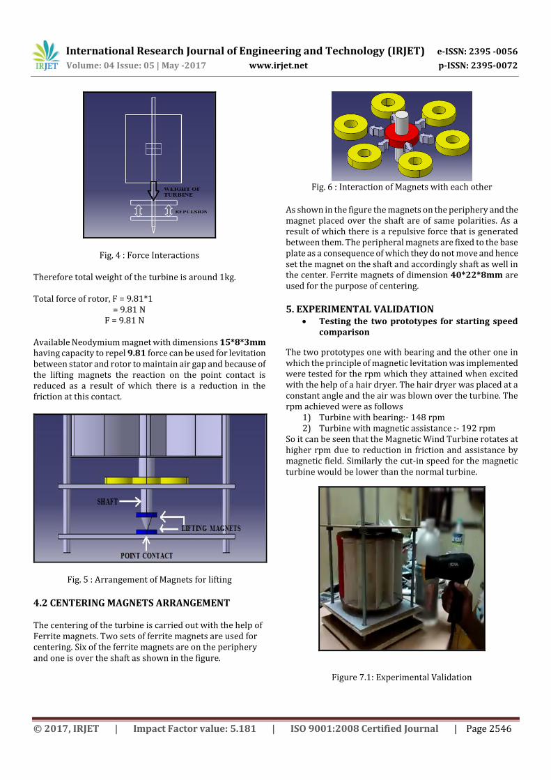
Fig. 6 : Interaction of Magnets with each other
As shown in the figure the magnets on the periphery and the magnet placed over the shaft are of same polarities. As a result of which there is a repulsive force that is generated between them. The peripheral magnets are fixed to the base plate as a consequence of which they do not move and hence set the magnet on the shaft and accordingly shaft as well in the center. Ferrite magnets of dimension 40*22*8mm are used for the purpose of centering.
5. EXPERIMENTAL VALIDATION
Testing the two prototypes for starting speed comparison
The two prototypes one with bearing and the other one in which the principle of magnetic levitation was implemented were tested for the rpm which they attained when excited with the help of a hair dryer. The hair dryer was placed at a constant angle and the air was blown over the turbine. The rpm achieved were as follows
1) Turbine with bearing:- 148 rpm 2) Turbine with magnetic assistance :- 192 rpm
So it can be seen that the Magnetic Wind Turbine rotates at higher rpm due to reduction in friction and assistance by magnetic field. Similarly the cut-in speed for the magnetic turbine would be lower than the normal turbine.
Figure 7.1: Experimental Validation

International Research Journal of Engineering and Technology (IRJET) e-ISSN: 2395 -0056
Volume: 04 Issue: 05 | May -2017 www.irjet.net p-ISSN: 2395-0072
© 2017, IRJET | Impact Factor value: 5.181 | ISO 9001:2008 Certified Journal | Page 2547
Consequently there is an increase in rpm by about:-
Hence it was experimentally validated that the Magnetic Vertical Axis Wind Turbine has lower starting speed and the arrangement of magnets so proposed assists the turbine in lowering the starting speed.
5. CONCLUSION
1) The initial speed required to excite the usual small scale wind turbine with bearings can be reduced by using the assistance of magnetic field. Also there is an increase in the rotational speed of the turbine when it is magnetically levitated. Above result was achieved due to reduction in friction which was possible because of magnetic levitation.
2) The use of the STAR CCM software to analyze the air
flow around a vertical axis wind turbine proved to be a very effective tool. A full analysis could be performed before any construction of such a project even began. The modeling of the curved blades and straight blade wind turbine allows the user to study the aerodynamics of various geometries at different physical settings to get a true feel for how the specific airfoil might behave in real world applications. Wind speeds of 10 m/s was studied. At the end it was concluded that the curved blade gave superior results in comparison to the straight blade and hence curved blade was considered into design.
3) The limitation of magnetic turbine is that very powerful permanent magnets are required .The central shaft has a bit of wobbly motion.
4) The wobbling of the shaft can be reduced by using strong permanent magnets and careful simulation of magnetic field.
REFERENCES
[1] Amit D. Patil, Amit W. Chake, Manoj I. Helonde, Pravin M. Gupta, “Vertical Axis Wind Turbine with Maglev Technology”, IJSRD -International Journal for Scientific Research & Development , Vol. 2, Issue 12, 2015 [2] Minu John, Rohit John, Syamily P.S, Vyshak P.A,“Maglev windmill”, International Journal of Research in Engineering and Technology, Volume: 03, Issue: 05, May-2012 [3] Kelvin J Van Dyke, “An introduction to magnetic levitation and its application”, IEEE, May-2014 [4] Minu John, Rohit John, “Maglevwindmill”, International Journal of Research in Engineering and Technology, Volume: 04, Issue: 05, May-2014 [5] Dinesh N Nagarkarand, Dr. Z. J. Khan, “Wind Power Plant Using Magnetic Levitation Wind Turbine”, International
Journal of Engineering and Innovative Technology Volume 3, Issue: 01, July 2013. [6] Vishal Dhareppagol, Maheshwari Konagutti, “Regenedyne maglev wind power generation”, International Journal of Electrical, Electronics and Data Communication, Volume- 1, Issue- 6,July 2010 [7] Mohammad M. Bashar, “Computational and Experimental Study on Vertical Axis Wind Turbine in Search for an Efficient Design”, Georgia Southern University, December 2014 [8] Javier Castillo Tampere, “Small-Scale Vertical Axis Wind Turbine Design” , University of Applied Sciences , December 2011 [9] Chetan Singh Solanki, “Renewable Energy Technology”, January 2008 [10] US 7,462,950 B2, (United States of America), Dec. 9, 2008, “MAGNETIC LEVITATION WEIGHT REDUCTION STRUCTURE FOR A VERTICAL WIND TURBINE GENERATOR”. [11] Thanhtoan Tran, Donghyun Kim and Jinseop Song , “Computational Fluid Dynamic Analysis of a Floating Offshore Wind Turbine Experiencing Platform Pitching Motion” ,May 2014 [12] Chris Kaminski, Austin Filush, Paul Kasprzak and Wael Mokhtar, “A CFD Study of Wind Turbine Aerodynamics”, Grand Valley State University, 2012 [13] V. B. Bhandari, “Design of Machine Element”, January 2013 [16] www.weatheronline.in/weather/maps/city