magnetically seeded bioreactor for three-dimensional ... · pdf filemagnetically seeded...
TRANSCRIPT

0
MAGNETICALLY SEEDED BIOREACTOR FOR
THREE-DIMENSIONAL TISSUE CULTURE A Major Qualifying Project Report
Submitted to the Faculty
Of the
WORCESTER POLYTECHNIC INSTITUTE
In partial fulfillment of the requirements for the
Degree of Bachelor of Science
By
___________________________ Alexander Chin
___________________________
Yuval Harel
___________________________ Artem Kutikov
Date: April 22, 2010
Approved:
___________________________ Prof. Marsha Rolle, PhD, Advisor
___________________________
Prof. Raymond Page, PhD, Advisor
___________________________ Prof. Christopher Lambert, PhD, Advisor
Key words:
1. Bioreactor
2. Magnetic beads
3. Dialysis culture

1
Table of Contents Authorship....................................................................................................................................... 4
Acknowledgments........................................................................................................................... 5
Abstract ........................................................................................................................................... 6
Table of Figures .............................................................................................................................. 7
Chapter 1 Introduction .................................................................................................................... 9
Chapter 2 Literature Review ......................................................................................................... 13
2.1 Differences Between 2-D and 3-D Cell Culture ................................................................. 13
2.2 Limitations of Three-Dimensional Cell Culture ................................................................. 14
2.3 Tissue Engineered Blood Vessels ....................................................................................... 15
2.4 Current Techniques for Tissue Engineered Blood Vessels................................................. 17
2.4 Bioreactors for Three-Dimensional Cell Culture ................................................................ 21
2.5 Magnetic Cell Positioning................................................................................................... 26
2.6 Patent Search ....................................................................................................................... 27
Chapter 3 Project Strategy ............................................................................................................ 32
3.1 Objectives ........................................................................................................................... 32
3.2 Revised Client Statement .................................................................................................... 34
3.3 Bioreactor Functions ........................................................................................................... 35
Chapter 4 Alternative Designs ...................................................................................................... 36
4.1 Functions-Means Tree ........................................................................................................ 36
4.2 Design Approaches ............................................................................................................. 38
4.3 Design Selection ................................................................................................................. 42
4.4 Preliminary Design ............................................................................................................. 47
Chapter 5 Design Validation ......................................................................................................... 50
5.1 Homogeneous Magnetic Field ............................................................................................ 50
5.2 Agarose Magnetic Beads .................................................................................................... 55
5.3 Cell-Bead Attachment ......................................................................................................... 61
5.4 Bead Mobility Validation ................................................................................................... 66
5.5 Validation of Dialysis Tube in Static Culture ..................................................................... 66
5.6 Validation of Bioreactors Central Rod in a Static Culture ................................................. 68
5.7 Microbead Seeding Estimation ........................................................................................... 69
Chapter 6 Discussion .................................................................................................................... 70
6.1 Bioreactor Design ............................................................................................................... 70
6.2 Bioreactor Materials Choice ............................................................................................... 70

2
6.3 Magnetic Beads ................................................................................................................... 71
6.4 Flow Paths ........................................................................................................................... 72
6.5 Economic Impact ................................................................................................................ 72
6.6 Environmental Impact ......................................................................................................... 73
6.7 Societal Influence................................................................................................................ 73
6.8 Political Ramifications ........................................................................................................ 74
6.9 Ethical Concerns ................................................................................................................. 74
Chapter 7 Final Design and Validation ......................................................................................... 75
7.1 Materials for Bioreactor Fabrication ................................................................................... 75
7.2 Bioreactor Assembly ........................................................................................................... 76
7.3 Fluid Flow Testing .............................................................................................................. 80
7.4 Bead Distribution Test ........................................................................................................ 82
7.5 Tissue Culture ..................................................................................................................... 85
Chapter 8 Conclusions and Future Work ...................................................................................... 88
Works Cited .................................................................................................................................. 91
Glossary ........................................................................................................................................ 97
Appendix A: Gantt Chart ............................................................................................................ 100
Appendix B: Pair-wise Comparison Chart ................................................................................. 101
Appendix C: Decision Matrices .................................................................................................. 102
Type of Magnetic Array.......................................................................................................... 102
Bead Seeding Method ............................................................................................................. 103
Flow System............................................................................................................................ 104
Appendix D: List of Materials for Final Bioreactor Design ....................................................... 105
Appendix E: Protocols ................................................................................................................ 105
Assembly of Bioreactor .......................................................................................................... 105
Homogeneous Magnetic Field Analysis ................................................................................. 106
Diffusion Validation of Inner Rod .......................................................................................... 106
Growth Media Preparation ...................................................................................................... 107
Rat Smooth Muscle Cell (RAMSC) Culture .......................................................................... 107
Cell Quantification .................................................................................................................. 108
Bead Fabrication ..................................................................................................................... 109
Bioreactor Tissue Culture Protocol ......................................................................................... 111
Removal of Tissue .................................................................................................................. 112
Masson Trichrome Stain Procedure ........................................................................................ 113

3
Hematoxylin and Eosin Staining Procedure ........................................................................... 114
Picrosirius Red Protocol ......................................................................................................... 115
Appendix F: Calculations ........................................................................................................... 116
Bead Concentration Approximation ....................................................................................... 116
Bead Seeding Calculations ..................................................................................................... 116
Bioreactor Media Flow ........................................................................................................... 116
Cost of Beads Materials .......................................................................................................... 118
MQP Budget ........................................................................................................................... 118

4
Authorship
All team members have contributed to each section of this report, as well as to all aspects
of the project, and we collectively accept responsibility for its content. Therefore, the group
wishes to decline the option of individual authorship.

5
Acknowledgments
The project group would like to acknowledge Lisa Wall and members of the Rolle,
Lambert and Gaudette labs for help with obtaining materials, answering questions and guiding us
throughout this project. We would like to specifically acknowledge Anna Maziarz, Aung Khang
and Eftim Milkani for their help with magnetic bead fabrication. We would also like to thank
Neil Whitehouse for his help with machining parts of the bioreactor, as well as Sharon Shaw
who helped with the histology work on our samples.
6
Abstract
Tissue engineering is a field which has shown great promise in developing cell-based
products to replace damaged or diseased tissue in the body. However, current tissue culture
techniques lack the ability to position cells into a desired three-dimensional shape without an
exogenous scaffold. The goal of the project was to design a bioreactor which has the capability
to position cells in three dimensions and support tissue growth. Collagen-coated agarose beads
seeded with rat aortic smooth muscle cells (RASMCs) were introduced into the bioreactor and
positioned on a magnetic rod, forming a tube. The magnetic rod, encapsulated by a dialysis tube,
contains a flow of fresh media, allowing nutrients to diffuse throughout the cultured tissue. A
secondary flow of media external to the rod allows for bead seeding and additional nutrient flow.
Fluid flow, cell-bead attachment, and bead seeding design aspects were validated and a proof-of-
concept was tested with cells. The device was able to run without contamination and met the
objectives of cell positioning, continuous nutrient flow, and ease of sampling.
7
Table of Figures Figure 2.1: Synthecon rotating bioreactor .................................................................................... 22
Figure 2.2: Dialysis tube-roller culture system. ............................................................................ 23
Figure 2.3: Flow-through bioreactor. ............................................................................................ 26
Figure 2.4: Packed bed bioreactor. ............................................................................................... 28
Figure 2.5: Bioartifical liver bioreactor. ....................................................................................... 29
Figure 2.6: Diffusion gradient bioreactor. .................................................................................... 30
Figure 2.7: Flow suspension bioreactor. ....................................................................................... 31
Figure 3.1: Weighted objectives tree. ........................................................................................... 34
Figure 3.2: Bioreactor functions. .................................................................................................. 35
Figure 4.1: Functions-means tree. ................................................................................................. 37
Figure 4.2: Magnetic rod bioreactor. ............................................................................................ 39
Figure 4.3: External magnet dialysis bioreactor ........................................................................... 40
Figure 4.4: Internal magnet dialysis bioreactor. ........................................................................... 41
Figure 4.5: Halbach array bioreactor. ........................................................................................... 42
Figure 4.6: Syringe bead seeding method. .................................................................................... 43
Figure 4.7: Manual rolling bead seeding method. ........................................................................ 44
Figure 4.8: Automated roller bead seeding. .................................................................................. 44
Figure 4.9: Dual reservoir flow system. ........................................................................................ 46
Figure 4.10: Semi-permeable membrane flow system. ................................................................ 47
Figure 4.11: CAD drawing of preliminary design. ....................................................................... 48
Figure 4.12: Magnetic rod assembly. ............................................................................................ 49
Figure 5.1: Blank magnetic paper. ................................................................................................ 51
Figure 5.2: Magnetic array with magnet polarization labeled. ..................................................... 52
Figure 5.3: Visualization of magnetic field from 6.35mm magnet spacing. ................................ 53
Figure 5.4: Visualization of magnetic field with no magnet spacing. .......................................... 53
Figure 5.5: Visualization of magnetic field 3.17 mm magnet spacing. ........................................ 54
Figure 5.6: Magnetic beads, 100X magnification. ........................................................................ 56
Figure 5.7: Bead fabrication schematic. ....................................................................................... 57
Figure 5.8. Collagen-coated beads stained with aniline blue, 100X magnification ..................... 59
Figure 5.9: Uncoated beads stained with aniline blue, 100X magnification ................................ 59
8
Figure 5.10: Uncoated stained BioScience beads, 100X magnification ....................................... 60
Figure 5.11: Collagen-coated stained BioScience beads, 100X magnification ............................ 61
Figure 5.12: Static cell-bead seeding, 100X magnification. ......................................................... 62
Figure 5.13: Hanging drop method. .............................................................................................. 63
Figure 5.14: Cell-bead attachment with hanging drop technique, 200X magnification. .............. 64
Figure 5.15: RASMC attached to collagen-coated beads, 100X magnification. .......................... 65
Figure 5.16: RASMC attachment to collagen-coated beads, 200X magnification. ..................... 65
Figure 5.17: Magnetic bead mobility test. .................................................................................... 66
Figure 5.18: Dialysis tube viewed with 200X magnification. ...................................................... 67
Figure 5.19: Central rod of the bioreactor. ................................................................................... 68
Figure 7.1: Rubber stoppers for bioreactor proof-of-concept. ...................................................... 77
Figure 7.2: Magnetic rod assembly. .............................................................................................. 77
Figure 7.3: Dialysis tubing attachment to magnetic rod. .............................................................. 78
Figure 7.4: Assembled bioreactor. ................................................................................................ 78
Figure 7.5: Bioreactor setup. ......................................................................................................... 79
Figure 7.6: Bioreactor setup for fluid flow validation. ................................................................. 81
Figure 7.7: Bioreactor fluid flow validation. ................................................................................ 82
Figure 7.8: Bead distribution with fluid flow. .............................................................................. 83
Figure 7.9: Bead distribution with syringe injection. ................................................................... 84
Figure 8.1: Bioreactor with side ports........................................................................................... 89

9
Chapter 1 Introduction
The field of tissue engineering has shown to be promising in harnessing the proliferative
capacity of cells to regenerate human tissue. Progress has been made in developing techniques
to culture cells under conditions which resemble those found in vivo. Bioreactors can aid in
replicating in vivo conditions by providing high rates of nutrient transport and mechanical
conditioning to a tissue culture. While culture conditions are important in guiding cell
differentiation and proliferation, the tissue also needs to form into the required geometry. There
is still no ideal method to seed and position high densities of cells into a specified three-
dimensional (3-D) shape. Additionally, there are limited methods to seed layers of multiple cell
types so that multi-layered tissues such as blood vessels can be efficiently recreated. The aim of
this project was to develop a bioreactor which can position cells into a 3-D construct and provide
an optimal environment for the cells to form a tissue.
Traditional cell culture involves growing cells in a flask or tissue culture dish where the
cells bind to a two-dimensional (2-D) surface. This technique produces conditions which do not
represent an in vivo environment, possibly resulting in a loss or change in cell differentiation and
function (Elsdale 1972). Frequent media changes are necessary in static culture systems while
limited diffusion of nutrients causes hypoxia within high-density tissue cultures (Darling 2005).
Bioreactors have emerged as tools to overcome the diffusion limitations of static culture and
more closely replicate in vivo conditions. Bioreactors culture cells in dynamic culture
conditions, where flowing media improves nutrient diffusion.
Bioreactors typically require a natural or synthetic scaffold to deliver the cells and define
tissue geometry. Scaffolds have a number of issues including biocompatibility (Williams 2008),
control of degradation rate (Dahl et al. 2007), cell migration into scaffolds even as small as 1.2

10
mm thick (Zhao and Ma 2005), mechanical mismatch with surrounding tissue (Weinberg and
Bell 1986), and alteration of cell phenotype (Higgins, Solan and Niklason 2003). This is
particularly harmful for tissue engineered blood vessels which need to withstand high
mechanical loads and recreate native morphology to prevent blood clotting and mechanical
mismatch. Thus, the recreation of blood vessels has been the topic of a significant amount of
scaffold-free tissue engineering research (L'Heureux et al. 1998, Ito et al. 2005, L'Heureux et al.
2006, Norotte et al. 2009).
Scaffold-free tissue engineered blood vessels have yielded promising results, but are
limited by the length of time and number manipulations involved in the manufacturing process.
For example, vascular grafts produced by CytoGraft, are made by culturing sheets of a patient’s
cells; manually rolling the cell sheets together, and then culturing the tubular product (Mcallister
and L'heureux 1999). This process takes approximately three months to complete (Mcallister
and L'heureux 1999), and could potentially be simplified if the cells could be positioned into a
tube without multiple culture steps. The tissue manipulation also incorporates additional room
for error. For the true recreation of a blood vessel, it is also important to mimic its three layers of
different cell types: endothelial cells (tunica intima), smooth muscle cells (tunica media), and
fibroblasts (tunica adventitia). The CytoGraft blood vessel is composed of only of fibroblasts
and endothelial cells (L'Heureux et al. 2006).
Therefore, there is still the unmet need for a system which can position a high density of
cells into a three-dimensional tissue and provide adequate nutrient transport for tissue growth.
The goal of this project was to develop a bioreactor which harnesses magnetic fields to
manipulate cell position and facilitate the formation of a tubular tissue construct. The device
should maintain proper conditions for optimal cell growth and enable fabrication of tissues
11
composed of multiple cell types. The product may be used to generate replacements for diseased
or damaged tissues (blood vessels), to study tissue function, or for bioprocessing.
The design team followed a five-stage prescriptive model for design, as directed by
Engineering Design: A Project Based Introduction by Clive I. Dym and Patrick Little. The first
stage was to meet with the clients to identify objectives and clarify the client statement. This
allowed for clarification of the problem and a formulation of conceptual and preliminary designs.
Engineering design tools were utilized to assess key aspects and develop a final design. The
principles behind the design were validated and a proof-of-concept prototype was built and
tested.
The client statement indicated the need for a bioreactor that will grow a 3-D tissue and
mimic an in vivo environment for that tissue. Prior to entering the design stage the team wanted
to get a better understanding of the problem and client statement. This was done by researching
topics that were related to the client statement to define the project in terms of previous research.
In order to better understand what has already been developed, a patent search and literature
review were conducted and is detailed in Chapter Two. Based on the background research and
meetings with the client, the design team was able to establish objectives that indicated a need
for 3-D cell positioning, continuous nutrient support, seeding of multiple cell types, ease of
manufacturing and sterile sampling. Constraints included a budget of $468, a deadline of April
22nd, 2010, and size (fits in an incubator). The objectives and constraints were used to revise and
clarify the client statement. A more detailed discussion of the design specifications, objectives,
constraints, and functions, is described in Chapter Three.
Based on the design parameters discussed in Chapter Three, several conceptual designs
were generated and are detailed in Chapter Four. Each part of the design including the flow

12
system, seeding methods, and magnetic array were then evaluated in a design matrix (as shown
in Appendix C). A preliminary design was developed and validation experiments were
performed to verify the principles behind the design as detailed in Chapter 5. In Chapter Six, the
validation experiments are discussed along with environmental, political, and economical factors
of the design. A proof-of-concept prototype was manufactured and the device’s capabilities
were verified in meeting the client’s objectives. The final design verification experiments, as
well as the fabrication, were documented and are detailed in Chapter Seven. In Chapter Eight,
recommendations for future work on the design were made based on the results and conclusions
of the validation experiments, so that future groups would be able to make improvements to the
design. Throughout the design process, the team attended regular meetings and maintained
contact with the client in order to receive feedback and update the client on the status of the
device. In order to complete the final design stage, the team submitted all documentation to the
client.

13
Chapter 2 Literature Review
Cell culture has long been vital to the advancement of biological sciences. The ability to
grow and manipulate cells in vitro opens innumerable possibilities for the discovery of
treatments and cures to various diseases, understanding of life on a cellular level, and creation of
living tissues (Moore and Ulrich 1965, DiCosmo and Misawa 1995, Goubko and Cao 2009).
The ability to create a 3-D functional tissue from cultured cells has applications not only in tissue
engineering, but also in understanding the human body and its complex functions (Griffith and
Swartz 2006). In order to fully understand the benefits of 3-D cell culture, it is important to first
explain the differences between 2-D and 3-D cell culture methods and what advantages 3-D cell
culture offers.
2.1 Differences Between 2-D and 3-D Cell Culture
Both 2-D and 3-D cell culture techniques are used for tissue engineering (Griffith and
Swartz 2006). Though each technique has its own benefits, it is important to highlight the
differences between them and the limitations each method has. The most notable difference
between 2-D and 3-D cell culture is the variation in morphology and cellular function that each
method produces (Griffith and Swartz 2006). In vivo, all tissue grows and functions in an
environment which allows for cell-cell interactions to occur. These interactions have been shown
to have an effect on how a cell’s function and morphology in a variety of cell types, including
hepatic cells, corneal and lung epithelial cells, and keratinocytes (Papini et al. 2005, Soletti et al.
2006, Sakai et al. 2010). When grown in on a 2-D culture dish were cell-cell interactions are
limited, cells have been shown to have function changes such as lower protein production and
altered morphology (Griffith and Swartz 2006). These differences are vital to creating cultures

14
that behave and function like in vivo tissue and allow a better understanding of how cells
function, grow, and interact (Toh et al. 2007).
Due to the increased resemblance to in vivo tissue, cell cultures grown in three
dimensions have an enormous value in tissue-engineered organs and research models (Abbott
2003). 3-D cell culture allows for function and morphology more closely related to cells grown
in vivo and allows for cells to grow in a thickness more like human tissue (Lichtenberg et al.
2005, Griffith and Swartz 2006). This thickness helps to make cell-cell interactions more
effective and provides an environment closer to that of in vivo growing cells, though this also
presents issues with nutrient and gas diffusion (Lichtenberg et al. 2005).
2.2 Limitations of Three-Dimensional Cell Culture
Difficulties have arisen with developing 3-D cell culture systems including the inability
to seed a large volume of cells, feed dense tissue cultures, maintaining cell function, and cell
survival. Though current methods prove the importance of 3-D cell culture in producing cells
that more accurately resemble in vivo function and morphology, these limitations must be
considered and addressed in order to develop a more successful method for 3-D cell culture and
the development of a functional tissue.
The ability to seed a large volume of cells is vital for successful tissue culture (Toh et al.
2007). Many cell culture techniques are unable to seed large volumes of cells, as well as control
positioning and provide structural support in the beginning of tissue formation (Martin, Wendt
and Heberer 2004). This limits the ability to form shapes that may be vital in final function of a
cultured tissue, such as with blood vessels (Conejo et al. 2007).
Another complication is the diffusion of media, gas, and nutrients through a 3-D culture
(Lichtenberg et al. 2005). Since growing cells in three dimensions necessitates an increased

15
thickness of tissue, it is also important to consider the diffusion capabilities of the culture
(Griffith and Swartz 2006, Goubko and Cao 2009). Depending on the thickness of the tissue, it
may be difficult to transport nutrients through the entire cell culture, causing cells in the center of
a tissue or farthest away from media flow to die (Lichtenberg et al. 2005). Studies have shown
difficulties with diffusion of nutrients and media through a cell culture with a thickness greater
than 2 mm (Griffith et al. 2005). Despite these limitations, 3-D cell culture is being used to
develop cells more like those found in vivo for various testing and tissue engineering projects
and is still being perfected (Abbott 2003). One important tissue engineering area that is taking
advantage of 3-D cell culture techniques is research involving vascular tissue and tissue
engineered blood vessels (Rhim and Niklason 2006).
2.3 Tissue Engineered Blood Vessels
In the creation of tissue engineered blood vessels, it is necessary to first understand in
vivo structure, function, and conditions so that these aspects can be replicated. Vascular tissue is
comprised of three main layers which gives its function and structure. The outer most layer,
known as the tunica adventitia, is composed of fibroblasts which provide mechanical strength
(Fox 2009). The middle layer of the blood vessel is called the tunica media and is the thickest
layer. It is comprised of smooth muscle cells in a collagen and elastin matrix. The tunica media
gives the blood vessel the ability to contract (Fox 2009). Smooth muscle cells are oriented in the
same direction within the tissue to give the tissue uniform properties and elasticity (Bolton et al.
2004). The inner layer, referred to as the tunica intima, is made of endothelial cells which have
direct contact with blood flow and prevents clotting within the blood vessel (Conejo et al. 2007,
Fox 2009).
16
Due to the various conditions that a vascular tissue must undergo, it is important to
understand their mechanical limits as well. Though the pressures and mechanical wear a blood
vessel is exposed to varies depending on size and location within the body, the majority of
vascular tissues used in treatments like coronary artery bypass surgery and arteriosclerosis
involve the use of the saphenous vein or mammary artery (Canver 1995). These burst pressures
of these vessels vary from 1599 ± 877 mmHg in the saphenous vein to 3196 ± 1264 mmHg in
the internal mammary artery (Konig et al. 2009). It would therefore be important for tissue
engineered blood vessels to fall within this range in order to provide adequate mechanical
support for blood flow.
Tissue engineered blood vessels are needed to treat a variety of diseases and traumas. For
example, arteriosclerosis is blockages or clots of plaque within an artery that can restrict blood
flow (Zhang et al. 2007). Though arteriosclerosis is most prevalent in men over the age of 50, it
can also affect young adults and woman with cholesterol conditions or poor dietary habits
(Association 2010). In 2004 in the United States alone, approximately 1.2 million people were
hospitalized due to arteriosclerosis. Expenses for treatment and hospital stays were estimated to
be around $44 billion (American Heart Association 2010). There are some pharmaceutical
treatments that may help clear this plaque but surgery is often the most effective option if the
blockage is too large (Yang, Bei and Wang 2002). In 2006, approximately 500,000 coronary
bypass surgeries were performed and that number is expected to grow as the population over 50
increases dramatically of the next few years (American Heart Association 2010).
Vessel replacement typically involves taking vascular tissue from a secondary site within
the patient in order to avoid donor-rejection complications, but this leaves the patient with a
secondary wound site and possible damage due to the removal of vascular tissue in the secondary
17
site (Hoenig et al. 2005). This surgery is also not possible on patients who have had a prior
transplant and do not have suitable vessels. The application of a tissue engineered blood vessel
could also go far beyond coronary artery bypass surgery to help victims of severe trauma to
vascular tissue (Stanec et al. 1997). The study of tissue engineered blood vessels continues to
grow with a better understanding of blood vessel disease, infection, and failure (Spiel, Gilbert
and Jilma 2008, Rohner et al. 2003, Ong et al. 2008).
With the availability of a tissue engineered blood vessel, patients would no longer need to
endure a secondary surgical site and treatments may be more readily available (Germain, Remy-
Zolghadri and Auger 2000). Even though the societal need is tremendous, there are still many
limitations to creating a successful vascular tissue, including possible calcification, infection, or
inability for the tissue to grow if implanted in a child or young adult (Rhim and Niklason 2006).
There are several techniques that are currently being tested and used in order to meet the need for
a tissue engineered blood vessels.
2.4 Current Techniques for Tissue Engineered Blood Vessels Despite the issues surrounding 3-D cell culture, various effective techniques have been
developed specifically to create tissue engineered blood vessels. Among the various ways blood
vessels are created, the majority of methods fall into two distinct categories: scaffold and
scaffold-free tissue engineered vascular tissue (Kim et al. 1998, Rhim and Niklason 2006, Ong et
al. 2008, ).
Scaffolds Polymer scaffolds provide structural support as cells grow and allow for cells to form a
tissue of a defined shaped (Baker and Southgate 2008). Generally, scaffolds are porous structures
that are biocompatible and allow for cell growth in and around the structure (Nair and Laurencin

18
2007). As cells grow and begin forming their own extracellular matrix (ECM), some scaffolds
are able to degrade over time leaving the tissue fully intact once it no longer needs the support of
the scaffold (Krenning et al. 2008). Scaffolds can also be tailor-made using various
combinations of polymer materials to control degradation rate, size, properties and cell
interactions and cost (Nair and Laurencin 2007). In the specific case of blood vessels, smooth
muscle cells can be seeded onto a polymer scaffold in order to allow for positioning as well as
structural support as the tissue begins to form and then degrade over time, leaving a formation of
smooth muscle cells in the desired shape and diameter size (Kim et al. 1998, Vaz et al. 2005,
Krenning et al. 2008).
One such example of a vascular tissue being created from a scaffold came from a group
who was able to use biodegradable poly(ester urethane) urea (PEUU) scaffolds to seed smooth
muscle cells (Nieponice et al. 2008). Using a specialized vacuum seeding technique, the seeded
the scaffolds with smooth muscle cells. After 7 days of culture, vascular grafts with
2127±900 mmHg burst pressures were formed. The group saw limitations in the inability to seed
endothelial cells into the scaffold as well as limitations with nutrient transfer in the spinner flask
culture system (Nieponice et al. 2008). Another group used a co-polymer Poly(ε-caprolactone)
(PCL) and collagen scaffold to create a vascular tissue by processing the two materials into a
thread-like consistency and combining them together through a process known as
electrospinning (Ju et al. 2010). Electrospinning is a process that spins polymer threads together
in order to create a scaffold with control of pore size through variations in the velocity at which
the scaffold is spun as well as the thickness of the threads used (Matthews et al. 2002). The
group was able to create a mechanically strong scaffold to support the cells and was able to seed

19
smooth muscle cells into the scaffold, though no vascular tissue was ultimately formed. They
hypothesized that this was due to a limited ability to seed cells into the scaffold (Ju et al. 2010).
Scaffold techniques often have issues with seeding a high density of cells as well as non-
uniform cell distribution, which is important for proper tissue formation (Martin et al. 2004).
Other issues with using scaffolds for blood vessel culture are that acidic or toxic scaffold
degradation byproducts and incomplete scaffold degradation which can affect the structural
integrity and shape of the final product (Dutta and Dutta 2009, Norotte et al. 2009). Though
scaffolds provide strong mechanical support initially, the ability to seed limited number of cells
as well as various other issues with degradation make this specific technique limited in its use for
tissue engineered blood vessels.
Cell Sheets Cell sheets are a technology that utilizes the natural ECM of cells in order to form a
scaffold to support cellular growth while avoiding the negative side effects of exogenous
scaffolds (Yang et al. 2007). Sheets are produced through culturing cells such as fibroblasts or
endothelial cells that produce ECM rapidly in a two-dimensional culture. The sheets are
harvested, the scaffold is decellularized and reseeded with the cell type of choice (Gao et al.
2009). Though chemicals originally used to decellularize the scaffold were found to weaken
ECM strength and cell-cell junctions within the cell sheets, Kushida’s group found that by using
temperature variations for cell culture, the same result could be achieved without damage to the
ECM (Kushida et al. 1999).
These sheets are then used as a scaffold-like structure and can be seeded with cells for
three-dimensional tissue engineering purposes, such as creation of blood vessels (L'Heureux et
al. 2006). L'Heureux’s group was able to create the first implantable and completely biological
tissue engineered blood vessel by creating cell sheets for a period of 6 weeks by co-culturing

20
fibroblasts and stem cells together, producing ECM sheets. Sheets were then cleaned using the
temperature variation method and smooth muscle cells were cultured on these sheets over a
mandrel to maintain a blood vessel shape for a maturation period of 8 weeks. They then lined the
tissue formation with endothelial cells to form the intima layer of the vascular tissue and found
three well-defined layers of tissue with a burst pressure strength of about 2000 mmHg.
Hematology tests and a preliminary in vivo test were preformed that confirmed that the blood
vessel could be implanted into a living subject (L'Heureux et al. 1998).
The largest limitation in this technique is the time needed to culture the smooth muscle
cells (approximately 8 week maturation) (L'Heureux et al. 1998). Another issue may be with the
need to use smooth muscle cells from the patient in order to avoid donor-rejection and the time it
would take to culture the cells (L'Heureux et al. 1998).
Cell Printing Cell printing, also known as Biological Laser Printing or BioLP, is a novel method for
positioning cells into 3-D constructs (Chen, Barron and Ringeisen 2006). This technology is able
to process cells into multi-layered culture by using ink-jet printing systems to “print” cells on top
of each other (Varghese et al. 2005). In the case of blood vessels specifically, cell printing
allows very accurate and precise control of tissue size and shape (Zhang et al. 2007). By loading
cartridges with cells and other biological aids such as growth factors and various other
biomolecules, this process is able to create a 3-D structure composed of a variety of components
(Xu et al. 2005, Chen et al. 2006). Once these multi-layer cultures are formed, they can then be
placed into a bioreactor for additional culture (Xu et al. 2005).
Due to the accuracy at which cell printing allows formation of tissue cultures, it has been
used to create vascular tissue (Cui and Boland 2009). The possible use of this technology could
be to replace microvascular damage in a patient which would be much more difficult with other

21
tissue engineering methods since there is less accurate control of cell positioning as compared to
cell printing (Zhang et al. 2007). Cui showed that by printing fibrin fibers for support,
endothelial cells were cultured into microvascular constructs after 21 days and could ultimately
become vascular tissue, though smooth muscle cells were not used in the experiment (Cui and
Boland 2009).
Cell printing is a robust method to produce a 3-D cell culture, but is yet to be seen as a
way to create viable tissue due to its inability to produce large massed cell cultures on its own
and lack of diffusion and transport through large thickness tissue (Varghese et al. 2005). Though
cell cultures can be fused together to achieve a desired shape, there is no guarantee that the cells
will fuse correctly or form enough ECM to hold together. The process is also time consuming
and costly due to the individual layering of the cells and growth factors, the need to load separate
cartridges, and the need to program the printer and computer to process and layer the cell culture
components correctly (Xu et al. 2005, Chen et al. 2006).
Among all the various methods for blood vessel tissue culture in 3-D, there are still
several limitations that are not addressed. Though these particular techniques don’t offer a
complete solution, the ability to use a bioreactor-type device may provide better results and
address more issues concerning blood vessel 3-D cell culture.
2.4 Bioreactors for Three-Dimensional Cell Culture
In order to have a better understanding of how to accomplish the objectives of our device,
we must first look into previous research and designs that have been pursued in the field of 3-D
bioreactors. Bioreactors are designed to mimic in vivo conditions while providing adequate
nutrient diffusion and waste removal. In order to arrange the cells and support cell growth,
typically a natural or synthetic scaffold is utilized. There are a number of 3-D scaffold-free

22
bioreactor systems, but methods to control of cell position are limited. Three bioreactor designs
that are capable of 3-D scaffold-free cell culture include the rotating wall vessel (RWV), dialysis
tube-roller, and the magnetically stabilized fluidized bed (MSFB).
Rotating Wall Vessel Bioreactor Rotating wall vessel (RWV) bioreactors were initially designed by the National
Aeronautics and Space Administration (NASA) to protect cell cultures from the extreme forces
of space shuttle launch and landing. The cells and media are suspended between two co-rotating
cylinders, which balance gravitational force with centrifugal force. This causes the cells to enter
a constant state of free fall, simulating the effects of microgravity. The RWV bioreactor allows
the cells to experience minimal shear and contact with the vessel. Subsequently the bioreactor
provides high rates of nutrient, waste, and oxygen transport. The cells aggregate in the center of
the bioreactor and engage in 3-D cellular interactions, such as extracellular matrix formation and
signaling (Lappa 2003). Figure 2.1 is an image of a commercially available RWV bioreactor
sold by Synthecon Inc.
Figure 2.1: Synthecon rotating bioreactor
Found at: http://www.bumc.bu.edu/microbiology/files/2009/10/doc2_clip_image002.gif
23
The RWV approach has shown to be promising in the field of tissue engineering and
long-term organ culture, particularly in the growth of high-density scaffold-free tissues (Ohyabu
et al. 2006, Sakai et al. 2009, Arrigoni et al. 2008). One disadvantage of the RWV is that there is
no way to define and dictate the 3-D shape of the tissue without using a scaffold. Also, the
effects of microgravity on cell growth are still under investigation (Sytkowski and Davis 2001).
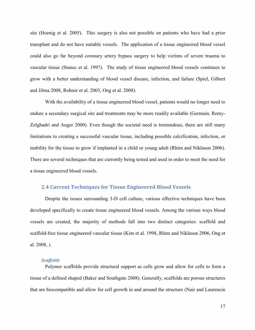
Dialysis Roller Bioreactor A team of researchers from the United Kingdom developed a dialysis tube-roller system,
shown in Figure 2.2 to culture scaffold-free tendon tissue (de Wreede and Ralphs 2009). Cell
pellets and media are added to a dialysis tube, inserted into a media filled centrifuge tube, and
placed on a roller. The system is allowed to culture for fourteen days. The researchers were
successful in producing rod-shaped aggregates with cell orientation similar to that of tendon (de
Wreede and Ralphs 2009). Using this method, the cells are undisturbed during media changes
and experience hemodynamic and physical loads with improved media flow around the
aggregates (de Wreede and Ralphs 2009). As with the RWV bioreactor, this system does not
allow for the manipulation of cell position in order to create a defined shape. The dialysis tube-
roller system produced a variation of aggregates in each tube including a majority of spherical
shapes, as opposed to elongated tendon-like fibers (de Wreede and Ralphs 2009).
Figure 2.2: Dialysis tube-roller culture system.
(de Wreede and Ralphs 2009)
a. Dialysis tube b. Conical tube c. Lid
Cells
24
BioLevitator A commercially available bioreactor that has the capability of creating 3-D tissue is the
BioLevitator®. This device is manufactured by Hamilton Robotics™ and Global Cell
Solutions™. The BioLevitator® is a bench top culturing device that “aims to streamline the cell
culture process.” The device uses beads, which are called Global Eukaryotic Microcarriers®
(GEM). Using the GEM, the device is able to magnetically maneuver the cells into position
inside a conical tube. These beads have the capability to interact with any type of cell line, which
allows for greater variety of tissue production (Perea et al. 2006). The device also allows for
control of temperature and CO2 levels which are vital to cellular growth. It is important to note
that even though this device has the capabilities to create 3-D tissues, it does have limitations.
Cells can adhere to the wall of the conical tube which causes cell formations in undesired areas.
The bioreactor has a static nutrient system which adversely affects diffusion and requires
frequent media exchange. In addition to these limitations, it has also been shown that the tissue
thickness is generally not larger than a few millimeters.
Magnetically Stabilized Fluidized Bed Magnetically stabilized fluidized bed reactors allow for continuous fermentation and
other high-throughput bioprocessing by suspending cells in flow of media with a magnetic field
(Terranova and Burns 1991). Cells are bound to magnetic particles and the particles arrange
themselves along the field lines produced by an electromagnet surrounding the reactor. Positions
of the particles can be adjusted by modifying the magnetic field.
Though magnetically stabilized fluidized bed (MSFB) reactors have not yet been used for
human cell culture, they may offer a number of advantages in this application. Having the cells
attached to these particles would allow them to receive a constant nutrient flow and waste
removal. Various bead formations can be formed by altering the magnetic field. Thus, the

25
MSFB can be used to both culture and orient cells. MSFB's have been applied to continuous
yeast fermentation (Ivanova et al. 1996), plant cell culture (Bramble, Graves and Brodelius
1990), and cell processing (Terranova and Burns 1991).
One issue which arises with the MSFB is the excessive heat produced by the
electromagnets, though there has been research on this topic (Terranova and Burns 1991).
Excessive heating of the bioreactor can cause denaturing of proteins and cell death. The MSFB
system allows for some manipulation of cell position, the formation of exact shapes is limited by
the inability to precisely control the magnetic field geometry.
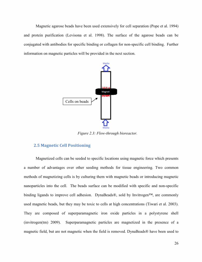
Flow-Through Bioreactor A team of researchers at Worcester Polytechnic Institute (WPI) led by Christopher
Lambert, PhD, have developed a ‘flow-through’ bioreactor which incorporates the principles of a
magnetically stabilized fluidized bed in a simplified form. A schematic of the design is shown in
Figure 2.3. Cells attached to magnetic beads are held in a ring arrangement by a permanent
magnet and fed by a constant media flow. A schematic of the flow-through bioreactor is shown
in Figure 2.3. The device is composed of a glass tube with a neodymium ring magnet positioned
outside the tube. The inside of the tube is coated with poly(ethylene glycol) (PEG) to prevent
cell attachment to the walls. The magnetic microbeads composed of agarose and iron oxide
nanoparticles are coated with collagen for cell binding. Although preliminary results are
promising, this approach is still in its infancy. The flow-through bioreactor has a number of
limitations which need to be overcome. One such limitation is the inability to monitor cell
growth in a minimally invasive and sterile manner. Another limitation is that there is no ability
to monitor bioreactor parameters such as pH, CO2, and temperature to assess bioreactor function
and media condition. Further, the cells in contact with the glass surface may receive limited
amounts of nutrients which would be detrimental to tissue formation.
26
Magnetic agarose beads have been used extensively for cell separation (Pope et al. 1994)
and protein purification (Levisona et al. 1998). The surface of the agarose beads can be
conjugated with antibodies for specific binding or collagen for non-specific cell binding. Further
information on magnetic particles will be provided in the next section.
2.5 Magnetic Cell Positioning
Magnetized cells can be seeded to specific locations using magnetic force which presents
a number of advantages over other seeding methods for tissue engineering. Two common
methods of magnetizing cells is by culturing them with magnetic beads or introducing magnetic
nanoparticles into the cell. The beads surface can be modified with specific and non-specific
binding ligands to improve cell adhesion. DynaBeads®, sold by Invitrogen™, are commonly
used magnetic beads, but they may be toxic to cells at high concentrations (Tiwari et al. 2003).
They are composed of superparamagnetic iron oxide particles in a polystyrene shell
(invitrogen(tm) 2009). Superparamagnetic particles are magnetized in the presence of a
magnetic field, but are not magnetic when the field is removed. DynaBeads® have been used to
Figure 2.3: Flow-through bioreactor.
Cells on beads

27
seed cells onto a tubular collagen membrane to form a tissue engineered blood vessel (Perea et
al. 2006). This technique is also applicable for recreating blood vessel structure by seeding
multiple cell types in succession (Perea et al. 2006). This approach was accomplished through
static culture, not within a bioreactor.
Ferrous oxide (Fe3O4) superparamagnetic nanoparticles have been delivered to cells and
used to make tubular cell constructs (Ito et al. 2004). The nanoparticles were encapsulated in
cationic liposomes in order to facilitate the nanoparticle delivery. The positively charged
liposomes are attracted to the negatively charged cell membrane, enter the cell and release the
nanoparticles (Ito et al. 2005). The magnetite-loaded cells were cultured into sheets and then
rolled onto a magnetic rod to form tubes (Ito et al. 2005). This method is called Mag-TE by the
authors and is described as an efficient approach to form high-density 3-D tissue constructs.
Directly loading magnetic particles into the cell could affect cellular function. Iron oxide
nanoparticles have been shown to decrease smooth muscle cell viability (Zhang et al. 2009), this
may be related to the poor mechanical properties of the cultured tissue (Ito et al. 2005). Another
disadvantage of this method is that tube formation required multiple tissue culture steps. First
the cell sheet needed to form, then the magnetic rod rolled over the sheet and finally the
construct was placed in a bioreactor to complete culture. However, this technique demonstrates
the promise of magnetically charged cells in tissue engineering.
2.6 Patent Search
Patent # US 4,833,083 A 1989 patent describes a bioprocessing reactor consisting of cells or enzymes bound to
microcarriers in a packed bed. A radial flow of media allows for continuous perfusion of the
microbead bed. The high surface area of media flow and cell binding surface area allows for

28
high density culture. This bioreactor, shown in Figure 2.4, is designed for the high throughput
production of proteins or other cell culture derived molecules (Saxena 1989).
Figure 2.4: Packed bed bioreactor.
(Saxena 1989)
Patent # US 4,988,623 Rotating Wall Vessel bioreactor technology has been marketed by Synthecon
Incorporated™ and is available in both disposable and autoclavable designs. This technology is
based on patent number 4,988,623 for a “Rotating bio-reactor cell culture apparatus” (Schwarz
and Wolf 1991). This patent was also expanded into a patent for a “Three-dimensional cell to
tissue assembly process” using the same rotating bioreactor while adding microcarrier beads to
increase cell attachment surface area (Wolf et al. 1992).

29
Patent # US 5,605,835 R.A. Shatford et al of the University of Minnesota designed a bioreactor with cells with a
culture chamber separated from a ‘waste chamber’ by a selectively permeable membrane. A
schematic of the design is shown in Figure 2.5. The cells are seeding into a fibrous gel which
allows for the diffusion of the waste through the membrane and into the surrounding media
stream (Hu et al. 1997). This bioreactor was designed to function as an extracorporeal liver
assist device, with hepatoctyes seeded in the gel matrix.
Figure 2.5: Bioartifical liver bioreactor.
(Hu et al. 1997)
Patent # US 5,827,729 Advanced Tissue Sciences holds a patent for a bioreactor which provides cells seeded
onto a mesh with two separate media flows. The reactor could also potentially function as an
extracorporeal liver assist device if used with liver tissue. Nutrients can be delivered to the cells
by a concentration gradient between the two media flows (Naughton, Halberstadt and Sibanda
1998). The bioreactor can be seeded with cells which produce a desired protein, such as
albumin, and the product harvested from either the media flows (Naughton et al. 1998). The

30
device, shown in Figure 2.6, can be used for co-culture of cells such as hepatic stormal and
acidophilic cells (Naughton et al. 1998).
Figure 2.6: Diffusion gradient bioreactor.
(Naughton et al. 1998)
Patent # US 6,632,658 B1 Levitronix LLC patented a bioreactor which suspends tissue in fluid flow (Schoeb 2003).
The device uses a cone to maintain a fluid flow gradient opposing gravity with the tissue in
equilibrium. The device can either suspend a tissue mass (with a scaffold) or cell pellets.
Though this bioreactor cannot control cell position, it does provide an example of the application
of fluid flow to control bulk position and cell suspension. A schematic of this bioreactor design
is shown in Figure 2.7.
Media flow
Cells on mesh

31
Figure 2.7: Flow suspension bioreactor. (Schoeb 2003)
Cell pellets
Fluid flow
Reservoir Pump

32
Chapter 3 Project Strategy
Following the prescriptive design process (Dym and Little 2004), the team initially
clarified the client statement and design objectives. The client gave the design team a project
outline, a timeline on expected deliverables, as well as a general client statement. A Gantt chart
was created to plan the project timing (Appendix A). The initial client statement was, “Generate
a ring of tissue in a flow through bioreactor that includes some engineering refinements that
allowed for non invasive monitoring of the system”. The team set out to clarify this general
statement through a series of client meetings and brain storming sessions. A detailed client
statement was constructed and several design tools were used to aid in developing a preliminary
design. Key components of the preliminary design were validated to fulfill client’s objectives
and a final design was constructed.
3.1 Objectives To conceptualize the design and focus the design space, a list of general objectives and
constraints were determined through discussion with the client. The objectives and constraints
were developed with a combination of background research, interviews, and team meetings. The
design team narrowed the objectives into five topics that the client conveyed were vital.
The device should ultimately culture a 3D tissue construct and provide adequete nutrient
diffusion to sustain the tissue growth. The bioreactors flow system should support a tissue of 1
mm thickness without necrosis in the center. A tubular tissue shape composed of smooth muscle
cells was specified as the 3D cell culture model due to its applicability to blood vessel tissue
engineering. At minimum the bioreactor should form a ring of tissue with a diameter of 5 mm.
The device should have the capabality of seeding multiple cells types and efficiently position the
seeded cells. This objective is applicable to recreate the layers of a blood vessel or form other 3-
33
D co-cultures, thus it was specified that the bioreactor should have the capability to seed three
subsequent layers of cells. It was also specificed that the bioreactor be capabable of seeding a
miniumum of 2 x 10⁶ cells. The clients also expressed the importance of the ability to sample
and asses bioreactor paramters and tissue growth. Ease of sampling was an objective the client
deemed vital in order to allow understanding of the development of the tissue, as well as possible
extraction of cells while still keeping the bioreactor running and sterile. The design should be
easily reproducable and require minimal machining. Ideally multiple bioreactors can be easily
manufactured and tested simultaneously.
A pair-wise comparison chart, shown in Appendix B, was completed in order to rank top-
level objectives. The main purpose of the pair-wise comparison chart is to narrow down the
components of the design that are vital to the client, as well as to allow the design team to focus
on the most important objectives (Dym and Little 2004). The pair-wise comparison chart given
to the clients and rankings were given on a 0 or 1 scale on which objective was more important
than its comparison, 1 meaning that the objective on the left was more important and 0 meaning
the top objective was more important. The design team also ranked the objectives as shown in
the grey boxes. The pair-wise comparison chart yielded a 3-D tissue was the most important
objective (4 points) followed by efficiency in cell positioning (2 points), ease of sampling (2
points), seeding of multiple cell types (1 point), and ease of manufacturing (0 points).
The rankings from the pair-wise comparison chart were used to create a weighted
objectives tree shown in Figure 3.1. The purpose of the weighted objectives tree is to consider
the objectives as taken from the pair-wise comparison chart and separate them into quantitative
considerations for planning the design (Dym and Little 2004). The chart shows that the client
deemed a three-dimentional tissue as the most important objective with multiple cell types and

34
ease of sampling tied for second. Efficiency in cell positioning and ease of manufacturing were
deemed objectives of lesser importance. These ratings allowed for a more focused attention on
the most important objectives and meeting what was vital to the project while also listing other
possible considerations for the device design.
Figure 3.1: Weighted objectives tree.
The team created a list of possible constraints that needed to be considered during the
brainstorming phase of the design process (Dym and Little 2004). The project had a budget of
$468 and a deadline of April 22, 2010. It was critical that the device fit on an incubator shelf,
thus size was a significant constraint. It was also necessary that the materials chosen to build the
device were capable of being sterilized and biocompatible with the cells used.
3.2 Revised Client Statement
Based on the initial client statement, several meetings with the client, and clarification of
design objectives, the design team was able to refine the client statement further.
The goal of this project is to create a magnetic bioreactor for three-dimensional cell culture and produce tubular tissue construct which can be used for blood vessel tissue engineering. The bioreactor will allow for manipulation of cell position into the three-dimensional shape without the use of a scaffold and provide continuous nutrient support to the tissue. The bioreactor should allow for sterile sampling of the tissue growth and produce an easily removable, three-
Bioreactor
3D Tissue(.45)
Seeding of multiple cell types
(.11)
Efficiency in cell positioning
(.22)
Ease of sampling(.22)
Ease of Manufacturing
(0)

35
dimensional tissue construct. The design should be easy to replicate and require minimal machining. The project should be completed within the $468 budget and by the April 22nd, 2010 deadline
3.3 Bioreactor Functions The design team determined four basic functions required to fulfill the client’s objectives,
summarized in Figure 3.2. The bioreactor should be able to seed a high density of cells
uniformly over the specified area and prevent exogenous tissue growth in other areas of the
reactor. This is necessary to accomplish the efficiency in cell positioning objective. The
bioreactor should position the cells into a tubular shape or tissue ring for blood vessel tissue
engineering. The tissue needs to receive sufficient nutrient support throughout the thickness of
the culture, preventing cell death in the center and aiding in the recreation of in vivo morphology.
Finally, the bioreactor design should incorporate the easy removal of the cultured tissue and
sterile sampling ports to assess bioreactor performance.
Figure 3.2: Bioreactor functions.
•Seed high density of cells•Seed and position multiple cell types•Limit exogenous tissue growth
Uniform cell seeding
•Formation of tissue ring •Blood vessel
Tubular tissue construct
•Prevent necrosis of three dimensional tissue•Provide nutrient diffusion to entirity of tissue•Continous nutrient flow
Optimal support of cell growth
•Removing tissue intact•Sampling biological product
Removable product
36
Chapter 4 Alternative Designs
Through brainstorming with the assistance of the design tools described in Chapter 3, the
design team decided upon four alternative designs for the bioreactor. The designs are based on
fulfilling the top-level objectives. Specifically, conceptual designs were developed that had the
capability to control cell position and provide appropriate conditions for the formation of a 3-D
tissue. The key features of each design were divided into three components; the type of magnetic
array, cell seeding method, and flow system. Decision matrices (Appendix D) were used to
determine optimal features of each design and a preliminary design was developed based on
these results. Computer-aided design software, SolidWorks 2009, was used to construct 3-D
models of the alternative designs.
4.1 Functions-Means Tree
The design team created the functions-means tree shown in Figure 4.1; which was used to
assist in brainstorming conceptual designs. The tree is meant to be present solutions to the
necessary functions of the design described in Chapter 3. The function-means tree shows several
means, shown in the rounded bubbles, to accomplish each function, denoted in the square boxes
at the top of each column. This would ultimately aid in developing possible design alternatives to
meet the primary objectives set by the client.

37
Figure 4.1: Functions-means tree.
In order to achieve uniform cell seeding, possible solutions may be syringe injection of
cells to allow direct and controlled placement. Another solution may be rotating the bioreactor to
allow for even coating and formation of a cylindrical shape. The bioreactor could also be rolled
and the cells would attach to it, or a Halbach array could be used to control where cells attached.
A Halbach array creates a homogenous magnetic field by positioning permanent magnets in
specific locations and orientations around a ring (Raich and Blümler 2004). The magnetic field
flux can be inside or outside the ring depending on the magnet arrangement (Raich and Blümler
2004). This field can be used to position the beads into a ring or potentially tube shape.
Optimal support for growth could be met by suspending the cells in media, using a semi-
permeable membrane to allow increased diffusion of nutrients into the cell culture. Controlled
Bioreactor
Uniform cell seeding
Syringe injection
Rotating bioreactor
Rolling onto a surface
Halbach array
Optimal support of cell growth
Suspension
Semi-permeable membrane
Controlled media flow
Tubular tissue construct
Walls of bioreactor
Around a rod
Magnetic field manipulation
Removable product
Non-adherent surface
Floating in bioreactor
Removable membrane
Monitoring of bioreactor function
pH
CO2
Temperature

38
media flow could be used to allow for better nutrient support. Alternative means would be to
suspend cell pellets or cells attached to beads in a flow of media.
A removable product could be achieved in several ways, through the use of a non-
adhesive surface, a floating bioreactor so that the device itself could be removed from the tissue,
or creating a removable device piece or membrane so that the tissue would not be compromised.
Monitoring certain aspects of the bioreactor would also be important to consider,
including pH, CO2 levels and temperature. The bioreactor could include means to monitor these
parameters in a minimally invasive manner. Cell growth could also be monitored by allowing
tissue samples to be removed while maintaining culture sterility.
4.2 Design Approaches
Magnetic Rod Bioreactor The bioreactor design in Figure 4.2 consists of a polymer coated magnetic rod within a
media filled chamber. Magnetic particles seeded with cells are loaded into the device and are
attracted to the magnet. The magnetic rod is coated with polymer so that the cells are not in
contact with metal and do not adhere to the surface. The cells are fed with continuously flowing
media. The bioreactor can also be rotated for improved cell seeding, nutrient transport, and
mechanical conditioning. Additional layers of different cell types could be added to the device,
allowing for the recreation of a blood vessel or other composite tissue. The magnetic rod array
would be simple and inexpensive to fabricate. This design succeeds in positioning cells,
supporting multiple cell types and forming a 3-D construct. However, there may be reduced
nutrient transport to the cells in contact with the magnetic surface. Another limitation is that it
may be difficult to remove the final tissue from the device, especially taking into account the
attractive forces exerted by the magnets.

39
Figure 4.2: Magnetic rod bioreactor.
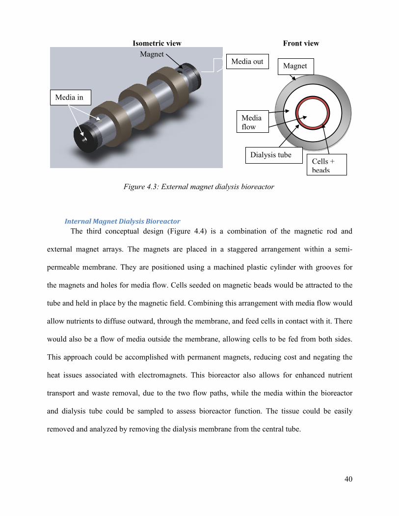
External Magnet Array Bioreactor The design alternative shown in Figure 4.3 suspends cells (on magnetic carriers)
within semi-permeable dialysis tubing and attracts them to the surface of the tubing by magnetic
force. This design allows for nutrient transport and waste removal to occur both within the
center and outside of the dialysis tube. The dialysis tube or the whole bioreactor could be rotated
for improved cell seeding. The strength of the magnets used could be a limiting factor in this
design due to the increased distance between the magnets and magnetic beads. Also, increased
difficulty could arise when removing the cultured tissue due to the possibility of the dialysis tube
collapsing upon itself. However, it may be easier to remove the tissue from this design than the
magnetic rod design because the beads would not be directly contacting the magnet.
40
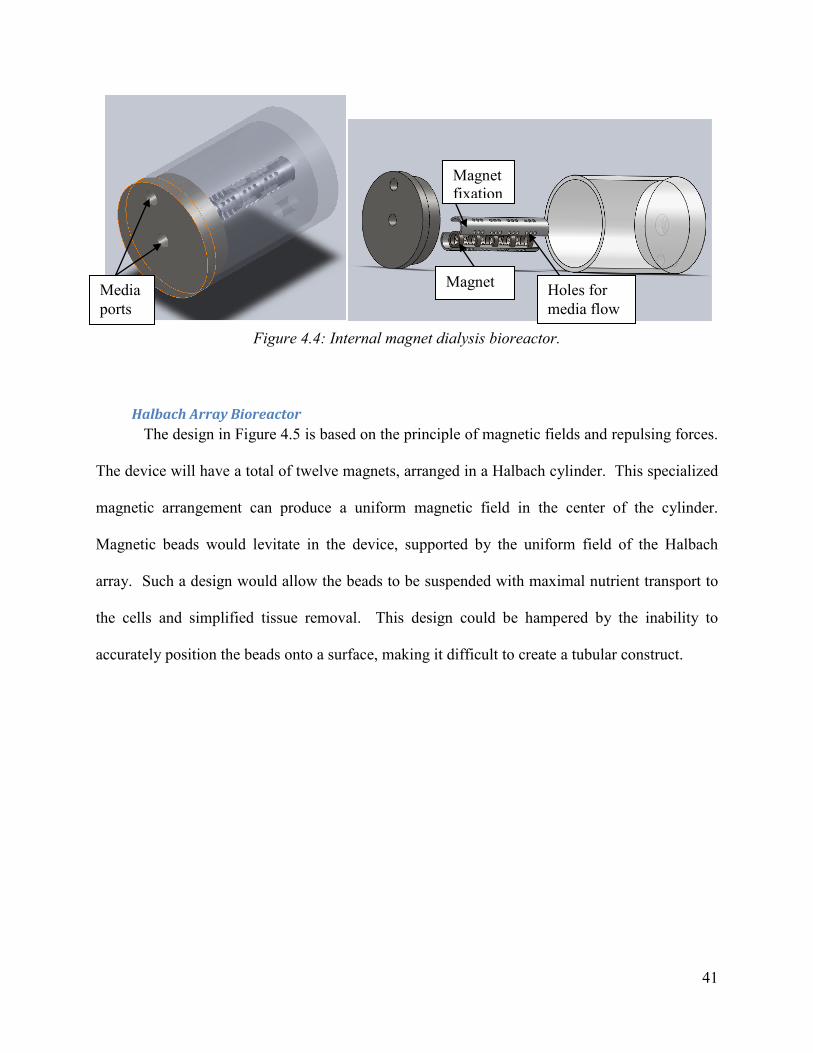
Internal Magnet Dialysis Bioreactor The third conceptual design (Figure 4.4) is a combination of the magnetic rod and
external magnet arrays. The magnets are placed in a staggered arrangement within a semi-
permeable membrane. They are positioned using a machined plastic cylinder with grooves for
the magnets and holes for media flow. Cells seeded on magnetic beads would be attracted to the
tube and held in place by the magnetic field. Combining this arrangement with media flow would
allow nutrients to diffuse outward, through the membrane, and feed cells in contact with it. There
would also be a flow of media outside the membrane, allowing cells to be fed from both sides.
This approach could be accomplished with permanent magnets, reducing cost and negating the
heat issues associated with electromagnets. This bioreactor also allows for enhanced nutrient
transport and waste removal, due to the two flow paths, while the media within the bioreactor
and dialysis tube could be sampled to assess bioreactor function. The tissue could be easily
removed and analyzed by removing the dialysis membrane from the central tube.
Figure 4.3: External magnet dialysis bioreactor
Front view
Magnet
Dialysis tube Cells + beads
Media flow
Isometric view
Media in
Magnet Media out
41
Figure 4.4: Internal magnet dialysis bioreactor.
Halbach Array Bioreactor The design in Figure 4.5 is based on the principle of magnetic fields and repulsing forces.
The device will have a total of twelve magnets, arranged in a Halbach cylinder. This specialized
magnetic arrangement can produce a uniform magnetic field in the center of the cylinder.
Magnetic beads would levitate in the device, supported by the uniform field of the Halbach
array. Such a design would allow the beads to be suspended with maximal nutrient transport to
the cells and simplified tissue removal. This design could be hampered by the inability to
accurately position the beads onto a surface, making it difficult to create a tubular construct.
Magnet Media ports
Magnet fixation
Holes for media flow

42
Figure 4.5: Halbach array bioreactor.
4.3 Design Selection
A decision matrix is an engineering design tool used to make design decisions. Each
design alternative is given a rank from 0 to 2 based on its adherence to given objectives,
functions, and constraints. The design alternative with the highest total score is considered
suitable for further development. Decision matrices were created for the bioreactor’s magnet
array, cell seeding method, and flow system (Appendix D). The values were tabulated for these
aspects of each conceptual design and the highest ranked approaches were incorporated into the
preliminary design.
Magnet Array The magnetic array decision matrix yielded the dialysis tube with internal magnets as the
optimal method to position the magnetic beads (Appendix D). This method allows for the

43
accurate positioning of cells within the device, high levels of nutrient transport on both sides of
the tissue, and the possibility of incorporating sterile sampling functionality.
Seeding Method After the magnet array was specified, it was important to determine optimal technique to
introduce beads into the bioreactor with an even distribution throughout the central tube. This is
important to prevent cell accumulation in one particular area leading to uneven tissue growth.
The team determined syringe injection, manual rolling, automated rolling, and pouring as
possible methods to seed the agarose microbeads into the bioreactor. Syringe injection would
involve either ports for a needle or luer-lock connections on the device. Beads could be injected
from multiple locations on the bioreactor thus aiding in even bead distribution. It would be
necessary to determine the optimal needle gauge and flow-rate to prevent cell detachment from
the beads. A schematic of this method is shown in Figure 4.6.
Figure 4.6: Syringe bead seeding method.
Alternatively, the magnetic tube could be manually rolled in a microbead solution. This
would guarantee and even distribution of particles on the tube’s surface. Though multiple cell
types could be seeded initially, it would be difficult to seed additional cells during culture,
because the bioreactor would need to be disassembled to remove the magnetic tube and roll it in

44
another bead solution. There would also be complications in maintaining sterility, because the
cells are seeded externally and then introduced to the bioreactor. A schematic of this method is
shown in Figure 4.7.
Figure 4.7: Manual rolling bead seeding method.
An automated roller system could be used to seed the beads and cells onto the magnetic
rod. Media containing cells attached to magnetic beads could be pipetted directly into the
bioreactor. The device can then be placed on a laboratory conical tube roller for a designated
period of time. The purpose of the rotation is to aid in even seeding of the beads on the magnetic
tube. This method is dependent on the rate of bead attachment to the magnets. If the beads
attach almost instantaneously, there would be an insufficient amount of time to disperse the
beads using the roller method. There could also be contamination issues involved with pipetting
media into the device. A schematic of the automated roller method is shown in Figure 4.8.
Figure 4.8: Automated roller bead seeding.
45
The final proposed method is to add the magnetic beads (with cells attached) directly into
the media reservoir. A peristaltic pump would be used to transfer the beads into the bioreactor
and disperse them along the magnetic tube. The rate of bead seeding and distribution could be
controlled through the flow rate of the pump. A higher flow rate would result in a more rapid
introduction of beads into the bioreactor. A greater spread of beads over the rod could be
achieved with this method, while increasing risks of cell detachment from the beads. Bead
distribution could not be controlled to a great degree of accuracy but this method would maintain
sterility of the device, because no external pouring or rod removal is necessary.
Syringe injection yielded the highest point total in the bead seeding decision matrix
(Appendix C). This approach allows for accurate and controlled bead positioning while
maintaining a sterile bioreactor environment. Luer-lock connections were chosen to provide a
secure and standardized syringe port. These connections can be positioned in optimal locations
on the bioreactor housing for uniform bead seeding. It is also necessary to specify loading rate
and syringe size, parameters determined through flow calculations and experimentation.
Flow System The flow system was an important design parameter which needed to be determined. The
most basic setup would involve a single media reservoir which would supply both fluid flows in
the bioreactor. This would be inexpensive to manufacture and would require only one pump. A
disadvantage of this setup is that detached cells would enter the shared media reservoir and
would be transferred into the magnetic tube. Thus the media would need to be replaced more
frequently and there could be cellular growth inside the magnetic tube causing decreased nutrient
transfer across the dialysis membrane. Also, there would be limited control of the flow rate in
the magnet tube and bioreactor housing.

46
The second approach involves using two media reservoirs and two pumps. One reservoir
would provide clean media to the magnetic tube and the second reservoir would circulate ‘dirty’
media in the bioreactor housing. The advantage of using two pumps is that the flow rate in the
magnetic tube and housing can be controlled individually and an optimal flow rate determined.
The optimal flow rate would provide the highest levels of nutrient and gas transport through the
dialysis tube and minimal levels of shear on the external cell layer. Dialysis tube function could
be quantified by comparing the composition of media in the reservoir supplying the dialysis tube
to the bioreactor housing reservoir. This approach would be more expensive due to the two
pumps and require larger amounts of media to operate. A multi-channel pump would also satisfy
this design, however flow rate could not be controlled as easily as a two pump system. A
schematic of the dual reservoir system is shown in Figure 4.9.
Figure 4.9: Dual reservoir flow system.
Another flow system was proposed which incorporates a semi-permeable membrane to
separate cell-free media and media with cells. This system could provide clean media to both the
magnetic tube and bioreactor housing, limiting extraneous cell growth in the device. Media
exiting the bioreactor would pass into the first section and be filtered through the dialysis

47
membrane to be pumped back into the device. This design could incorporate either a single
pump or two pumps for improved flow control. A schematic of the semi-permeable membrane
flow system is shown in Figure 4.10. The flow system decision matrix yielded the dual reservoir
approach as the optimal flow system for the bioreactor.
Figure 4.10: Semi-permeable membrane flow system.
4.4 Preliminary Design The results of the decision matrices were used to develop a preliminary design. This
design incorporates the internal magnet dialysis tube, syringe injection bead seeding and a dual
reservoir flow system. SolidWorks 2009 was used to build a 3-D model of the preliminary
design, determine appropriate dimensions and guide fabrication of the device. A model of the
preliminary design is shown in Figure 4.11. All dimensions listed are in millimeters.

48
Figure 4.11: CAD drawing of preliminary design.
The preliminary design is composed of a dialysis tube and housing with independent
media flow systems. In the center of the dialysis tube is an array of two magnets, secured on a
threaded rod with hex nuts. The dialysis tube runs over the magnets and is secured by zip-ties to
two graduated pipette end pieces. The pipette ends are inserted into rubbers stoppers with holes
for media flow. A model of the magnetic tube is shown in Figure 4.12. All dimensions listed are
in millimeters.

49
Figure 4.12: Magnetic rod assembly.
The bioreactor housing is a tube which is sealed by the rubber stoppers. This could be
fabricated by cutting the end off a conical tube, thus expensive machining is not required. Luer-
lock connections could be attached on the surface of the tube, enabling the injection of media or
magnetic bead solution.

50
Chapter 5 Design Validation
The central aspects of the bioreactor design included the ability to attach cells to
magnetic beads, attract the beads to a magnet, and provide nutritional support to the culture with
a dual-flow dialysis tube system. These principles behind the design were validated prior to
testing the final design of the bioreactor.
5.1 Homogeneous Magnetic Field
Due to the incorporation of magnetized beads for cell positioning within the bioreactor, a
homogeneous magnetic field was of significant importance. The need for such a field was to
assure that the beads would spread evenly around the bioreactor. This would allow for a more
confluent cell growth around the inner tube of the bioreactor.
In order to determine if the device had a homogeneous magnetic field to which the beads
and cells could attach to, a particular magnetic paper was used that was designed to allow a
visual demonstration of where the magnetic fields lines were located, when placed over an
object. This paper, sold through Millipore, contained a slurry of ferromagnetic nickel particles.
With an absence of a magnetic field the paper appeared green, but when a magnetic object is
placed under the paper, the magnetic slurry is displaced which changes the papers color from
green to black. Below is an image of the magnetic paper without any object or magnetic field
underneath it.

51
Figure 5.1: Blank magnetic paper.
In order to test whether the orientation of magnets would produce a homogenous
magnetic field, this magnetic paper was used to give a visual representation. Using the rare earth
magnets purchased for our design, they were assembled in various orientations on the nylon rod
in order to determine which set up would produce the most homogenous magnetic field and thus
allow for a more even distribution of magnetic beads on our magnets. The magnets, purchased
through KJ Magnets, were N52 neodymium rare earth magnets, which denote the type of
material used (N for neodymium) and the strength of each magnet on a scale of 42-52, in which
52 is the highest strength magnet. These magnets were polarized from horizontally, meaning that
the top half of the magnet was polarized north while the other was polarized south. The image
below shows one magnet with the north and south ends labeled for a clearer understanding of
how the magnets are polarized.

52
Figure 5.2: Magnetic array with magnet polarization labeled.
The magnets needed to be separated so that the field is homogenous across the length of
the rod. Previous research with homogenous magnetic field testing was referenced in order to
make a homogenous magnetic field (Okuda 1995, Okuno 1997). The exact distance of separation
depended on several variables including type of magnets used and strength of the magnets. Since
no literature could be found referencing N52 magnets, the team decided to try variable distances
and use the magnetic paper to visually check how homogenous the magnetic field was. The
magnetic field was tested with a nylon hex nut (6.35 mm), nylon washer (3.17 mm) and no
spacer between the magnets to see which produced the most homogenous field. The ideal
outcome of the test would be to see the magnetic paper turn black evenly along the entire length
of the rod. This would show that there was a completely homogenous field around the magnets
and rod and that no spaces existed where there was no magnetic field.
The first test was conducted testing the magnetic field with a nylon hex nut between the
two magnets. Figure 5.3 shows the magnetic rod (left) and field on magnetic paper (right).

53
Figure 5.3: Visualization of magnetic field from 6.35mm magnet spacing.
From the image on the magnetic paper, it was determined that the magnetic field did not
look uniform around the inner rod. There were clear holes of green were the field was not
effective, specifically around the inner hex nut as well as directly in half of each magnet. The
holes in the middle of the magnet were determined to be due to the polarization of the magnet
(each magnet was magnetized North and South in half from left to right as shown in Figure 5.2).
The next test that was conducted was to see if no hex nut would produce a more homogenous
magnetic field since the use of the hex nut caused a void in middle of the rod. The results are
shown in Figure 5.4.
Figure 5.4: Visualization of magnetic field with no magnet spacing.
The results of the test showed that this setup generated a less homogenous field, creating
a large void in the middle of the rod and two homogenous fields on the end. This would result in

54
large clumping when beads were introduced and would not produce an even distribution of cells
along the entire length of the bioreactor. It was speculated that these results were produced due
to the polarization of the magnets. The magnets produced a strong attractive field where they
would touch, but produced a large resistive field half way between them since the magnets are
polarized north and south on the left and right sides, as seen in the picture. This polarization
causes the fields to cancel each other in that area, producing no magnetic field and thus a less
homogenous image. The last test that was conducted was to place a thin nylon washer between
the magnets instead of the nylon hex nut. It was thought that this might allow for a more
homogenous magnetic field than the nylon hex nut because the magnets would be slightly closer
together, but not close enough to where a large void would be generated in the center of the rod.
The field resulting from the 3.17 mm magnet spacing is shown in Figure 5.5.
Figure 5.5: Visualization of magnetic field 3.17 mm magnet spacing.
This set up produced a much smaller gap between magnets, but there was still a small
area where the field was not homogenous located in the middle of the magnets on the nylon rod.
Though the result did not show a completely homogenous magnetic field, the voids in the field
were due to the magnets themselves and seen in both the test with no spacer and with the nylon
hex nut. What the nylon washer did show was a stronger and more uniform magnetic field in the
center of the rod.
55
Taking into consideration the results of all three tests, it was determined that using the
washer between the magnets produced the most homogenous magnetic field out of the three
methods tested. Though using different magnets may help in making the magnetic field more
uniform such as the use of concentrically polarized magnets (polarized north and south from the
inside to the out respectively) due to lack of availability and time constraints, this was not
possible for the purposed project.
5.2 Agarose Magnetic Beads
Collagen-coated agarose beads were fabricated based on a protocol developed by Dr.
Christopher Lambert’s lab at WPI. The beads were prepared through an emulsion of a melted
3% agarose/iron oxide nanoparticle solution in soybean oil. Bead formation was confirmed with
light microscopy as shown in Figure 5.6. Carboxyl groups were activated on the beads, enabling
the binding of collagen onto the surface of the beads by the formation of amide bonds. The
beads were sterilized with 70% ethanol prior to activation and coated with sterile Bovine Type 1
collagen (Advanced BioMatrix). While agarose typically does not support cell adhesion, cells
can bind to the collagen coating with integrins on the cell surface (Humphries 2000).

56
Figure 5.6: Magnetic beads, 100X magnification.
Bead Fabrication It was necessary for the iron oxide particles to be of nanoscale for them to fit within the
agarose beads and exhibit superparamagnetic properties (Tong and Sun 2001). The size of iron
oxide particles was validated with oil-immersion light microscopy. Precise measurements of the
particles could not be obtained with the microscope available but the size scale was determined.
The iron oxide particles were produced in the form of a ‘magnetic fluid’ or iron oxide particles in
a dodecanoic (lauric) acid solution. The lauric acid was necessary to prevent particle
agglomeration, maintaining the nanoscale particle size (Tong and Sun 2001). The magnetic fluid
was prepared by dissolving Iron (II) chloride tetrahydrate (Alfa Aesar) and Iron (III) chloride
hexahydrate (Alfa Aesar) in a lauric acid (Alfa Aesar) solution and precipitating out iron oxide
with ammonia.
100 μm
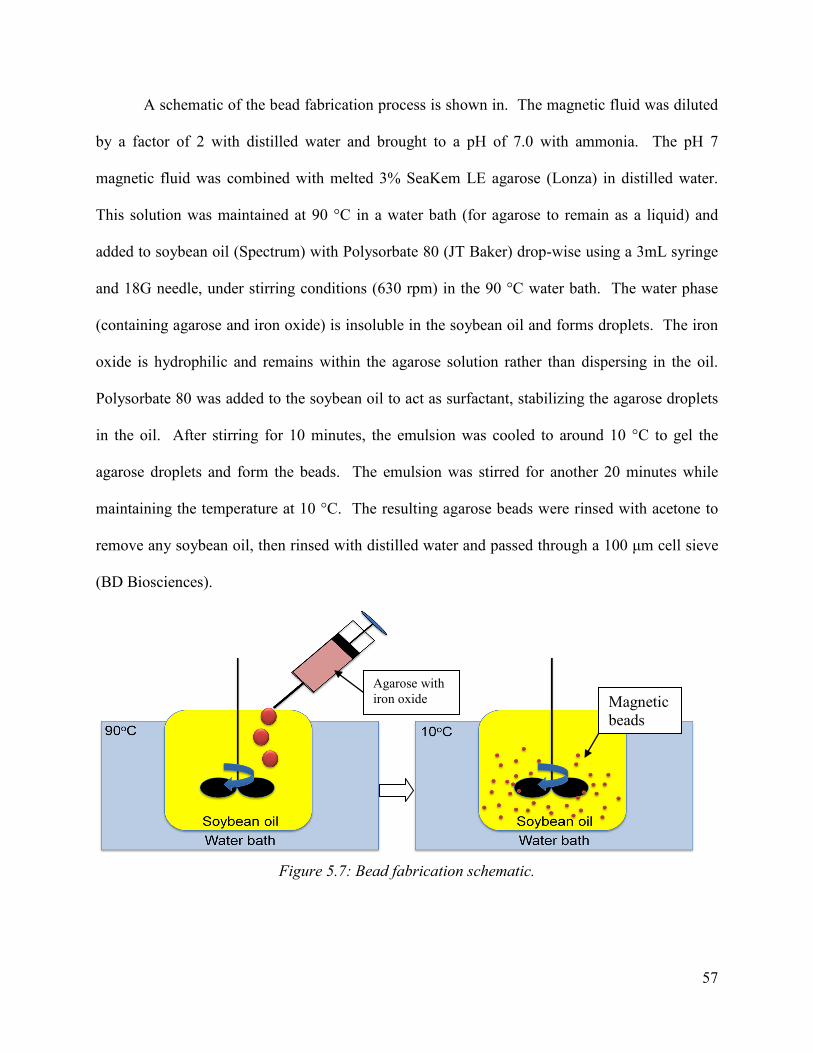
57
A schematic of the bead fabrication process is shown in. The magnetic fluid was diluted
by a factor of 2 with distilled water and brought to a pH of 7.0 with ammonia. The pH 7
magnetic fluid was combined with melted 3% SeaKem LE agarose (Lonza) in distilled water.
This solution was maintained at 90 °C in a water bath (for agarose to remain as a liquid) and
added to soybean oil (Spectrum) with Polysorbate 80 (JT Baker) drop-wise using a 3mL syringe
and 18G needle, under stirring conditions (630 rpm) in the 90 °C water bath. The water phase
(containing agarose and iron oxide) is insoluble in the soybean oil and forms droplets. The iron
oxide is hydrophilic and remains within the agarose solution rather than dispersing in the oil.
Polysorbate 80 was added to the soybean oil to act as surfactant, stabilizing the agarose droplets
in the oil. After stirring for 10 minutes, the emulsion was cooled to around 10 °C to gel the
agarose droplets and form the beads. The emulsion was stirred for another 20 minutes while
maintaining the temperature at 10 °C. The resulting agarose beads were rinsed with acetone to
remove any soybean oil, then rinsed with distilled water and passed through a 100 μm cell sieve
(BD Biosciences).
Figure 5.7: Bead fabrication schematic.
Agarose with iron oxide Magnetic
beads

58
Activation and Collagen Coating Carboxyl groups were coupled to the surface of the beads in order to facilitate collagen
attachment. ‘Inactivated’ carboxyl groups on the beads cannot react to form amide bonds
without high temperatures or the presence on an initiator. Activation was accomplished by
soaking the beads in a solution of .02M N-Hydroxysuccinimide (NHS) and .1M 1-Ethyl-3-(3-
dimethylaminopropyl) carbodiimide (EDC). The EDC is a carbodiimide which loosely binds to
the carboxyl groups on the agarose. The NHS displaces the EDC, forming a more stable
structure. NHS coupled to the carboxyl groups allows for the formation of amide bonds in the
presence of an amine (such as L-lysine on collagen). The beads were placed on a shaker at low
speed and allowed to soak in the EDC/NHS solution for 20 minutes. They were then rinsed with
distilled water and coated with collagen in a 9.6pH buffer solution. The beads were stored in
distilled water until they were ready to use.
Aniline blue was used to verify the presence of collagen on the beads surface (Figure
5.8). Bead which were active but uncoated were stained with the aniline blue as a control
(Figure 5.9). Beads were visible with blue traces attached however a majority of beads did not
appear to stain positive.

59
Figure 5.8. Collagen-coated beads stained with aniline blue, 100X magnification
Figure 5.9: Uncoated beads stained with aniline blue, 100X magnification
100μm
100 μm
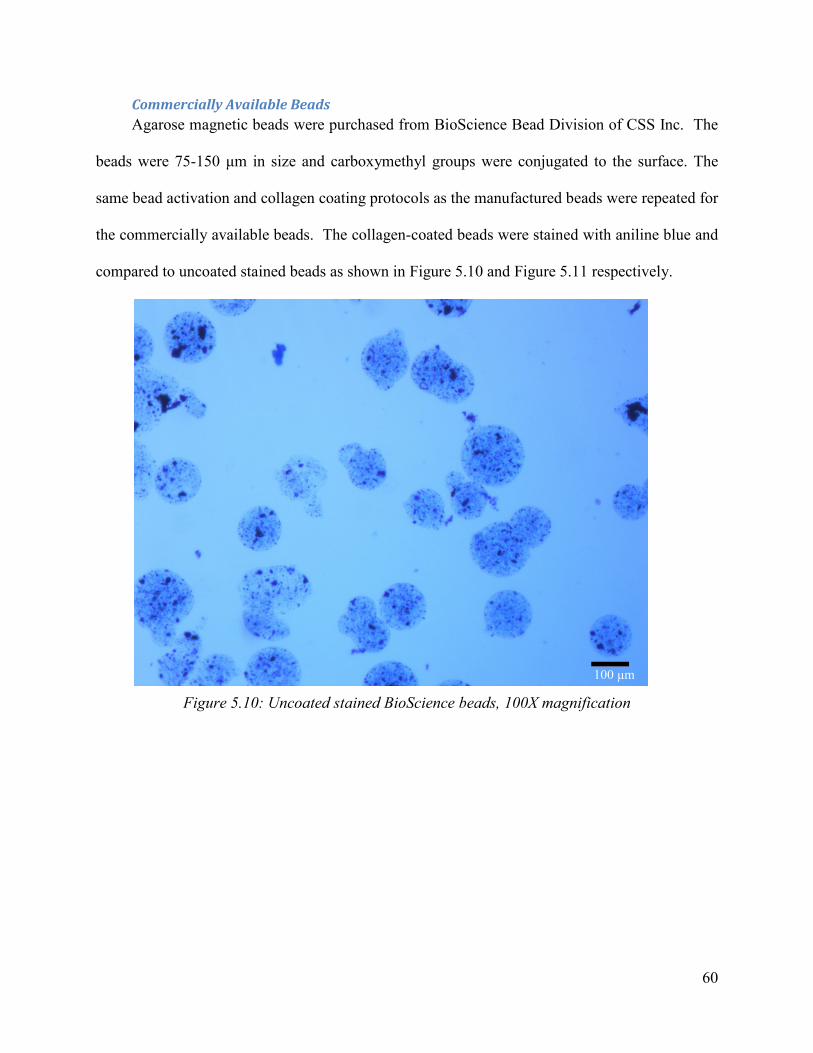
60
Commercially Available Beads Agarose magnetic beads were purchased from BioScience Bead Division of CSS Inc. The
beads were 75-150 μm in size and carboxymethyl groups were conjugated to the surface. The
same bead activation and collagen coating protocols as the manufactured beads were repeated for
the commercially available beads. The collagen-coated beads were stained with aniline blue and
compared to uncoated stained beads as shown in Figure 5.10 and Figure 5.11 respectively.
Figure 5.10: Uncoated stained BioScience beads, 100X magnification
100 μm

61
Figure 5.11: Collagen-coated stained BioScience beads, 100X magnification
5.3 Cell-Bead Attachment
Rat aortic smooth muscle cells (RASMCs) were chosen as the cell type based on
availability and budget constraints. It was necessary to validate the principle that cells can be
attached to collagen-coated beads and to estimate the numbers of cells attached per bead. A
number of methods were tested and the optimal seeding method was determined. Prior to cell
attachment, the beads were centrifuged and the distilled water was removed. They were rinsed
three times with PBS, centrifuging and removing supernatant between each rinse. A final rinse
with cell culture media was performed and supernatant was removed. Protocols for bead
fabrication and cell attachment are described in Appendix E.
100 μm
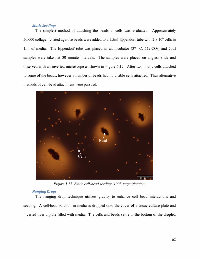
62
Static Seeding: The simplest method of attaching the beads to cells was evaluated. Approximately
50,000 collagen-coated agarose beads were added to a 1.5ml Eppendorf tube with 2 x 10⁶ cells in
1ml of media. The Eppendorf tube was placed in an incubator (37 °C, 5% CO2) and 20µl
samples were taken at 30 minute intervals. The samples were placed on a glass slide and
observed with an inverted microscope as shown in Figure 5.12. After two hours, cells attached
to some of the beads, however a number of beads had no visible cells attached. Thus alternative
methods of cell-bead attachment were pursued.
Figure 5.12: Static cell-bead seeding, 100X magnification.
Hanging Drop: The hanging drop technique utilizes gravity to enhance cell bead interactions and
seeding. A cell/bead solution in media is dropped onto the cover of a tissue culture plate and
inverted over a plate filled with media. The cells and beads settle to the bottom of the droplet,
100 μm
Bead
Cells

63
increasing the probability that cell binding will occur. The media within the dish prevents the
droplets from drying. An illustration of this technique is shown in Figure 5.13.
A concentration of 2 x 10⁶ cells in 1ml of media were added to an Eppendorf tube
containing approximately 50,000 beads. 20 μl droplets were formed on the tissue culture plate
cover using a micropipette. The cover was inverted and placed over a tissue culture dish filled
with media. The hanging drop system was allowed to culture for 30 minutes. The cover was
removed from the dish and placed on an inverted microscope for observation. As shown in
Figure 5.14, a high concentration of cells was visible around the beads with a significant amount
of cell attachment. However, the feasibility of this technique is limited by the small volume of
the droplets making it difficult to seed a significant quantity of beads with cells.
Cell + bead solution
Culture plate cover Culture plate cover
Media
Invert
Droplet close-up
Bead
Cell
Cover
Figure 5.13: Hanging drop method.

64
Figure 5.14: Cell-bead attachment with hanging drop technique, 200X magnification.
Dynamic Seeding: In order to improve the binding efficiency of the cells in a sufficient volume, the solution
of beads and cells in media was placed on a rotator and incubated for 2 hours. The solution was
rotated at low speed, based on the DynaBeads® ClinExVivo cell isolation protocol by Invitrogen
(Dynal 2007). After incubation, 50 μl of the media was placed on a microscope slide and imaged
with a phase contrast microscope. The number of cells per bead was counted in 7 fields of view
at 100X magnification. The cells appear bright due to the difference in light diffraction from the
cell compared to direct light entering the objective. A total of 63 cells were counted on 19 beads
or an average of 3.3 ± .49 cells/bead. The cell count had a standard deviation of 2.16 cells. One
field of view at 100X magnification is shown in Figure 5.15; white arrows denote smooth muscle
cells attached to beads. A field of view at 200X magnification is shown in Figure 5.16.
100 μm

65
Figure 5.15: RASMC attached to collagen-coated beads, 100X magnification.
Figure 5.16: RASMC attachment to collagen-coated beads, 200X magnification.
100 μm
50 µm
Cell Bead

66
5.4 Bead Mobility Validation
The maximum distance to attraction of the beads by a magnet was assessed. The purpose
of this test was to determine the susceptibility of the beads to the magnetic field and the
feasibility of positioning the beads with a magnet. The test would also aid in determining
dimensions for the design where all seeded beads can attach to the magnet. A tissue culture dish
was marked at .5 cm increments along the diameter. A magnet was placed at one end of the dish
and 50 μl of bead suspension was ejected at .5 cm intervals toward the magnet. The test was
performed with 5 mm outer diameter X 3.1 mm inner diameter X 5 mm long and 12.7 mm outer
diameter X 6.35 mm inner diameter X 12.7 mm long cylinder magnets. The magnets were
wrapped in Teflon tape to aid visibility of the beads and bead removal. The beads were attracted
1 cm from the 5 mm outer diameter magnet and 1.5 cm from the 12.7 mm outer diameter
magnet.
Figure 5.17: Magnetic bead mobility test.
5.5 Validation of Dialysis Tube in Static Culture The dialysis tube is an essential part of the design that separates the central flow of clean
media of the bioreactor from the external media flow. Also, part of the design is to have a
removable product and that is why it is essential that the cells would not be able to attach
Magnet
Beads Magnet
Beads
1 cm
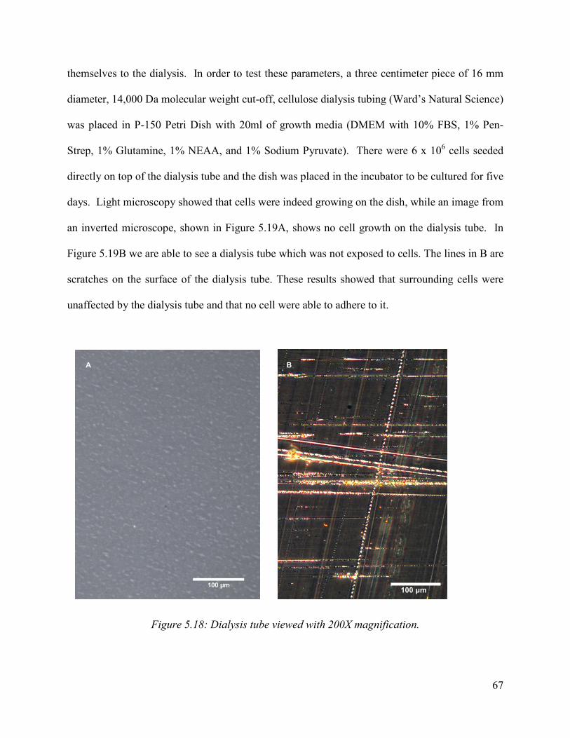
67
themselves to the dialysis. In order to test these parameters, a three centimeter piece of 16 mm
diameter, 14,000 Da molecular weight cut-off, cellulose dialysis tubing (Ward’s Natural Science)
was placed in P-150 Petri Dish with 20ml of growth media (DMEM with 10% FBS, 1% Pen-
Strep, 1% Glutamine, 1% NEAA, and 1% Sodium Pyruvate). There were 6 x 10⁶ cells seeded
directly on top of the dialysis tube and the dish was placed in the incubator to be cultured for five
days. Light microscopy showed that cells were indeed growing on the dish, while an image from
an inverted microscope, shown in Figure 5.19A, shows no cell growth on the dialysis tube. In
Figure 5.19B we are able to see a dialysis tube which was not exposed to cells. The lines in B are
scratches on the surface of the dialysis tube. These results showed that surrounding cells were
unaffected by the dialysis tube and that no cell were able to adhere to it.
Figure 5.18: Dialysis tube viewed with 200X magnification.
100 μm
A B

68
5.6 Validation of Bioreactors Central Rod in a Static Culture The central rod of the bioreactor (as shown in Figure 5.19) is a primary element of the
design. It attracts the beads with cells, acts as a barrier between the magnets and the cells, as well
as between the internal flow and external. A principle element that needs to be observed is
whether the central rod could indeed attach beads onto it and allow for an ECM to form.
Figure 5.19: Central rod of the bioreactor.
The central rod of the bioreactor was placed in a P60 Petri dish with 40 ml of media
(DMEM with 10% FBS, 1% Pen-Strep, 1% Glutamine, 1% NEAA, and 1% Sodium Pyruvate).
A cell bead mixture of 50,000 beads to 2 x 10⁶ cells, which was cultured on a rotator inside an
incubator for two hours, was pipetted directly onto the central rod. The rod was rotated four
times during the pipetting of the beads, in order to promote even distribution of cells and beads
around the rod. The Petri dish was placed in the incubator to culture for five days. Once the five
days have passed, the dialysis tube was removed from the central rod and was placed in
Formalin, a chemical used to fix cells, for two hours. Once fixation was complete, the dialysis
tube was placed in 70% ethanol until it was processed to be cut into five micron slices. Once the
slices were placed on a slide, they were stained with Hematoxylin and Eosin stain (H&E),
Masson's Trichrome Stain, and Picrosirius Red Stain.
Magnet

69
H&E stain uses the basic dye hematoxylin, which colors basophilic structures with blue-
purple hue, and alcohol-based acidic eosin Y, which colors eosinophilic structures bright pink.
The basophilic structures are ones containing nucleic acids, while eosinophilic structures are
ones with extracellular protein (Laboratories 2007). Masson's Trichrome Stain is a three colored
stain were red represents keratin and muscle fibers, blue or green represents collagen and bone,
light red or pink represents cytoplasm, and dark brown to black represents cell nuclei (Dako
2010). Picrosirius Red Stain is used to stain collagen I and III and is viewed as a red color
(PolySciences 2009). All the stains which have been described will show the structure of the
ECM and indicate what morphological and chemicals structures are present. Unfortunately, no
tissue formation was found in the H&E stain.
5.7 Microbead Seeding Estimation
The volume of agarose beads required to seed the magnetic tube of the bioreactor was
estimated. This was accomplished through calculating the surface area of the magnetic tube and
dividing this by the area of a bead. This calculation was based on the assumption that the
average bead size is 100 µm and that a layering the tube with a single layer of beads would be
sufficient to culture a tissue. The surface area of the effective tissue culture tube (distance along
the two magnets) was divided by the cross-sectional area of a bead. The bioreactor would
require 279,680 beads to operate or .28 ml of settled beads. However, it was specified that a
minimum of 2 X 10⁶ could be seeded at one time. It is also likely that a minimum number of
cells are required to form a confluent tissue. Based on the cell-bead attachment experiment
described in Chapter 5.3, approximately 4 cells attach per bead so a minimum of 500,000 beads
(.5 ml) would be necessary. While experimentation could be conducted to determine the optimal
volume of beads, initial trials of the bioreactor could contain up to 2ml of beads in order to

70
assure a sufficient number of cells are seeded for further validation experiments. Complete bead
quantity calculations are shown in Appendix F.
Chapter 6 Discussion
The following chapter will discuss and evaluate the design decisions and applicability of
the validation experiments. It is important to discuss these various aspects in order to understand
why the bioreactor was built in the way it was utilizing the various materials involved in the
process. The various ramifications of the design were also explored from a variety of viewpoints.
6.1 Bioreactor Design
The fabrication of the bioreactor required simple machining that took four hours to
perform and required two hours to assemble. The time required to machine the device could be
minimized if a professional machinist would have been used. The cost of building the device
was less than $80, due to being comprised of commonly found lab items, but it is also important
to note that many of the materials that were ordered for the device, such as the nylon rod, hex
nuts and washers, had to be ordered in bulk because they are not sold separately.
6.2 Bioreactor Materials Choice
The materials which were picked for the development of the device were chosen for
several reasons. It was important to choose materials that were biocompatible and would not
leach any harmful toxins or chemicals into the bioreactor during use. Another consideration was
the price of each material, considering our limited budget of $468 and the availability of each
item. The 50N nickel-coated neodymium magnets, nylon thread, nylon hex nuts, nylon washers,
71
polystyrene conical tube, polystyrene pipette tip, cellulose dialysis tubing, and silicone tubing
were all purchased for the price of $59.12. The manufacturing and assembly cost associated with
working these materials was $0, while the cost of running each experiment was $24.40
(calculations seen in Experimental Cost supplement). The incorporation of these costs yielded a
final cost of $336.71.
6.3 Magnetic Beads
The bead fabrication process required three days and approximately 8 hours of laboratory
work. The cost of materials for a yield of approximately 2 ml of beads was $24.17. The bead
validation experiments suggest that collagen-coated agarose microbeads can be effective cell
carriers and can be positioned by permanent magnets. By counting attached cells under a phase
contrast microscope, we were able to approximate an average of 3.3 cells attached per bead.
Collagen staining of the beads suggested that the coating process could use improvement
because some of the beads had collagen attached while a number of beads did not stain positive
for collagen. This collagen coating is likely the limiting factor in cell attachment because cells
typically cannot attach to agarose (Sakai, Hashimoto and Kawakami 2007). It is possible that the
surface of the beads did not get activated properly, thus the collagen could not bind.
Commercially available magnetic agarose beads (75-150 μm diameter, carboxymethyl
activated) were purchased from the BioScience Bead Division of CSS Inc. for $7 per ml. The
collagen coating process was repeated on the commercially available agarose magnetic beads
and yielded a more robust result. However, the surface of the beads did not appear to be
uniformly coated in collagen which limits cell binding sites. Time constraints did not permit
repeating the cell attachment validation study with the commercial beads.

72
6.4 Flow Paths
The media flow paths of the device were a key element of the design, because they may
allow for nutrient flow to diffuse to both the center and the outside of the formed tissue. Media
flow rates for the central rod and outer housing were 8 ml/min. and 23 mL/min., respectively.
Such flow should maximize diffusion of growth media to cells and potentially prevent cell death
within the center tissue. The addition of the dialysis tube may also allow the tissue to culture
under conditions more closely resembling in vivo due to the increased surface area exposed to
nutrients. Another purpose of the dialysis tube other than acting as a semi-permeable barrier
between the central flow path and external flow path is its capability of preventing the cells and
beads from contacting the magnets at the center. This allows for simplified removal of the final
tissue through removal of the dialysis tube. The two tests were performed to validate that the two
separate flow paths could co-exist while the dialysis tube allowed easy removal of the beads
from the magnet.
6.5 Economic Impact
If the bioreactor was able to successfully produce 3-D tissues that were approved for
clinical usage by the FDA, it would be a giant leap in tissue engineering. The development of
such a tissue would eliminate the need for autologous vessels and synthetic grafts. Also, the
development of such a tissue would inspire the tissue engineering community to try and use this
method to develop other organs, potentially eliminating the need for organ donors. The potential
cost that would go into creating such tissues would be counterbalanced by the drugs needed to
accommodate autologous vessels, synthetic grafts, and organs which were donated. Also, the
cost that are associated with complications that might occur as a result of using autologous

73
vessels, synthetic grafts, and organs which were donated, would also counterbalance the cost
associated with harvesting of cells need to grow the tissue in the bioreactor. Another potential
application of this device is in research, were the tissue formation could be used to do bench top
testing of drugs. The cost of developing the tissue would be outweighed by the costs needed to
maintain animal models, potentially eliminating the need for food, shelter, and permits to test on
the animals.
6.6 Environmental Impact
The development of the device was based on commonly used laboratory equipment,
described in detail in Chapter Four. The usage of these materials would not require any special
development of any parts of the device, but only gathering of materials from outside venders.
This would decrease the amount of machining needed to create the device and decrease the
amount of energy needed to develop it. Also, if the device was to be implemented into a
commercial phase, the only environmental implication of the device would be its sterilization,
which would have to be done using ethylene oxide.
6.7 Societal Influence
The capability to grow a cardiovascular graft would aid a large portion of society,
allowing them to donate their cells to replace vessels in their own bodies. A successful
development of such a tissue would be a huge help in the treatment of arteriosclerosis,
thrombosis, and various trauma incidents involving damage to vascular tissue (Hoenig et al.
2005). Heart bypass surgeries would no longer require secondary wound sites and removal of a
vein in order complete the procedure, as well as being more readily available to patients without

74
the worry of donor-rejection or disease transfer that may be common with current transplants
(Susa et al. 2009).
6.8 Political Ramifications
With the current usage of rat aortic smooth muscle cells in the development of tubular
cell tissue, no political ramifications can be seen. However, the creation of a device that could
produce a 3-D tissue may lead to the pursuit of the using stem cells to culture tissue. Though
there is an ongoing political and ethical debate over the morality of the use of stem cells (which
is outside the scope of this paper), the bioreactor does not need to specifically use these types of
cells, and it is believed that the device itself would not cause political ramifications.
6.9 Ethical Concerns
As tissue engineering progresses, ethical issues and concerns rise. The potential to save
lives may be looked at favorably when it comes with the development of blood vessel grafts.
However, the device could be used to pursue research with stem cells, which would raise ethical
concerns. The issue of whether life begins at the formation of cells or at birth is both an ethical,
religious, and political debate that has surrounded stem cell research ever since its discovery
(Edwards, Gearhart and Wallach 2000). Though there is an ongoing political and ethical debate
over the morality of the use of stem cells (which is outside the scope of this paper), the
bioreactor does not need to specifically use these types of cells. The ethical concern of the usage
of the device are minimal, when excluding stem cells, and lays the ethical responsibilities on the
user which chooses the cell which are going to be used in the device.

75
Chapter 7 Final Design and Validation
7.1 Materials for Bioreactor Fabrication Several types of materials were used in the final design of our bioreactor. Such materials
include nylon hex nuts, nylon washers and a nylon threaded rod, rare earth magnets, a conical
tub, two 25ml pipette ends, and rubber stoppers (a complete list of materials can be found in
Appendix D). These materials were each specifically picked for our design in order to meet our
design objectives and budget constraints.
Materials such as the peristaltic pump, pipettes and conical tubes were supplied by the
Biomedical Engineering Department at WPI and used in validating the design. The serological
pipettes and conical tubes were used and cut for the purposes of our bioreactor. The dimensions
are demonstrated in our final CAD drawing seen in Figure 4.11.
The nylon thread and screws were both chosen to accommodate the inner diameter of
25ml pipette ends and a 50ml conical tub, as well as for price and material
(http://www.usplastic.com/). Nylon is an inert material that is non-toxic and can withstand the
potentially corrosive environment of the bioreactor. The usage of a nylon threaded rod
eliminated the need to pre-treat the rod to resist cell or biomolecule adhesion. Also, using this
rod allowed the magnets to be secured through the usage of nylon hex nuts on either end. The
inner diameter of the rod was chosen based upon the size of the available pipette ends, which
was 1.5 cm. Nylon being a relatively inexpensive material that costs $4.60, made it an ideal
choice for the inner threaded rod.
The magnets we chose for our design were nickel neodymium rare earth magnets
(http://www.kjmagnetics.com/). We chose these particular magnets based on their magnetic
strength and dimensions as well as price. These magnets have a strength that was noted as N52

76
which gives some indication as to the magnetic strength and therefore magnetic field the magnets
would produce. N refers to the type of material the magnet was made from, neodymium, and the
52 represents the grade of material used in the magnet. The grade of material correlates to the
strength of the magnetic field produced, ranging from N42-N52 with 52 being the highest
possible strength (http://www.kjmagnetics.com/neomaginfo.asp). Since the magnets needed to fit
on the nylon rod, we chose magnets that had an inner diameter of 0.635 cm like that of the rod
and an outer diameter of 1.2 cm.
Silicon tubing was also purchased in order to connect the media chambers, bioreactor, and
pump together. Silicon tubing was chosen since it allows carbon dioxide exchange through the
bioreactor as well as being inexpensive and readily available. An inner diameter of 1.58 mm was
purchased for the inner rod and 3.17 mm was used since it was available for free through the
Worcester Polytechnic Biomedical Engineering department. Since it was desired to have a
slower flow in the central rod, the variation in diameter would not have a negative effect on the
bioreactor.
7.2 Bioreactor Assembly
Assembly The materials listed in Appendix D were used to assemble the final bioreactor. Parts such
as the nylon rod, conical (polypropylene) tube, and 25 ml serological pipette ends were cut to the
specified lengths of our design (as seen in both Figure 4.11 and Appendix E). Two holes (12.7
mm in diameter) were drilled into the rubber stoppers in order to allow for the two flow systems
in the final design. For one rubber stopper, a hole was placed in the center of the rubber stopper
for flow to the inner rod of the bioreactor (12.7 mm in diameter) while the other was placed
approximately 2-5 mm above the center hole to allow for outer fluid flow (8.38 mm in diameter),

77
as shown in Figure 7.1A. For the other rubber stopper, an additional hole (8.38 mm in diameter)
was drilled into the rubber stopper on the opposite side in order to install a port for seeding beads
into the bioreactor, as seen in Figure 7.1B.
Figure 7.1: Rubber stoppers for bioreactor proof-of-concept.
The magnet array (as determined from the magnetic field validation test) in the inner rod
of the bioreactor was constructed by positioning the magnets on the center of the threaded nylon
rod and securing them in place with nylon nuts. Figure 7.2 shows the materials used in the
construction of the inner rod (left) and the magnetic array secured on the threaded nylon rod
(right).
Figure 7.2: Magnetic rod assembly.
B
A B
Pipette ends
N52 magnets
Nylon washer
Nylon threaded rod
Nylon hex nuts

78
The magnets are N52 grade and composed of nickel plated neodymium. In order to
prevent nickel corrosion and the release of potentially toxic ions, the magnets could be coated
with a hydrophobic silicone layer using Sigmacote (Sigma-Aldrich) but this was not applied to
the bioreactor proof-of-concept. An additional nylon nut was placed on each end of nylon thread
in order to secure a serological pipette end which was place over the end of the rod as shown in
Figure 7.3 (left). The entire rod was then enclosed with 16 mm diameter (14,000 Da MW cutoff)
dialysis tubing that was zip tied at the ends of the rod, as can be seen in Figure 7.3 (right). The
central rod construction was placed in a polypropylene tube and enclosed with two rubber
stoppers, as shown in Figure 7.4.
Figure 7.3: Dialysis tubing attachment to magnetic rod.
Figure 7.4: Assembled bioreactor.
Zip Ties
Dialysis tubing
Stoppers
Magnets
Pipette Ends
Nylon Rod and Hex Nuts
Conical Tube

79
Tubing was connected into the holes drilled into the rubber stoppers to allow for fluid
flow and silicon sealant was used to prevent fluid leakage from the rubber stoppers. The
bioreactor was then connected to a multichannel pump and media reservoirs with CO2 permeable
silicone tubing. The length of the tubing (a total of 20 ft) was used in order to connect the
bioreactor to the media reservoirs within the incubator and the pump which was located external
to the incubator. Figure 7.5 shows the fully constructed bioreactor with pump and media
reservoirs.
Figure 7.5: Bioreactor setup.
Sterilization Prior to testing the bioreactor, all materials were cleaned with 70% ethanol and placed in
the sterile hood. A 70% ethanol solution was circulated through the bioreactor, tubing and media
boxes. Following the ethanol, two PBS washes where passed through the bioreactor, tubing and
media boxes to assure that no ethanol was remaining. Although this procedure is not considered
Multi-channel pump
Tubing coil
Media reservoir
Bioreactor

80
a sterilization technique, this procedure was satisfactory to prepare the device for cell culture.
Antibiotics in the cell culture media also aided in the prevention of contamination.
7.3 Fluid Flow Testing
After full assembly of the bioreactor, the flow system needed to be tested in order to
determine the flow path of fluid through the bioreactor, if the bioreactor would leak, and if there
are two distinct media flows from the inner tube and the outer tube.
In order to test the flow system, an experiment was set up that would flow clear water
through the outer tubing and green food-colored water through the center tube. Since the dialysis
tubing used in the design of the project has such a small pore size, no food-colored water
diffused from the inner tube to the outer tube. This allowed visible conformation that there were
two distinct fluid systems. Figure 7.6 displays the initial set up of the system prior to the addition
of green dye. Tubing was connected from the water beakers, through the peristaltic pump which
compressed the tubing to generate a flow of determined to be about 8 ml/min for the inner flow
and about 23 ml/min for the outer flow. Tubing then went from the exit of the bioreactor back
into the beakers of water.

81
Figure 7.6: Bioreactor setup for fluid flow validation.
In order to determine the fluid flow rate, specifications of the peristaltic pump were
needed. Using the Dynamax user guide by Rainin, found in Appendix F, calculations of the fluid
could be based on the type of tubing, length of tubing, and the inner diameter. Using the
calculated table provided by the user guide, the flow was determined to be about 8 mL/min for
the inner flow, with a tubing diameter of 1.58 mm, and about 23 mL/min for the outer flow, with
a tubing diameter of 3.17 mm (Appendix F). These flow rates were close to the desired flow
rates needed for the bioreactor.
Figure 7.7 shows the bioreactor running with a distinct flow of green water through the
center of the tube with no leaks into the outer tubing. This test shows that no leaks occurred on
the outer part of the bioreactor, as well as within the inner tube itself, which was the expected

82
result. The test provides a proof of concept and validation for the design of the bioreactor and
shows that all the designed and manufactured parts work as intended.
Figure 7.7: Bioreactor fluid flow validation.
7.4 Bead Distribution Test
Flow Based Distribution Test was conducted to see how fluid flow would affect bead distribution along the inner
rod. The same setup as shown in Figure 7.7 was used. A syringe was used to inject the beads
into the tubing of the bioreactor. After injecting beads into the tubing and reconnecting the
bioreactor to the pump circulation, the pump was turned on. Figure 7.8 shows the results of the
test and how the beads attracted to the rod. In the image, fluid is flowing from the left, into the
bioreactor, and out on the right side of the picture.
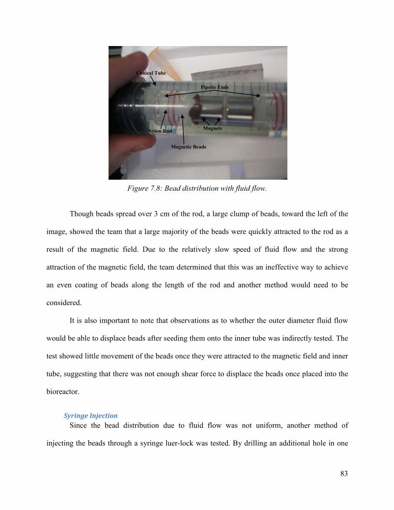
83
Figure 7.8: Bead distribution with fluid flow.
Though beads spread over 3 cm of the rod, a large clump of beads, toward the left of the
image, showed the team that a large majority of the beads were quickly attracted to the rod as a
result of the magnetic field. Due to the relatively slow speed of fluid flow and the strong
attraction of the magnetic field, the team determined that this was an ineffective way to achieve
an even coating of beads along the length of the rod and another method would need to be
considered.
It is also important to note that observations as to whether the outer diameter fluid flow
would be able to displace beads after seeding them onto the inner tube was indirectly tested. The
test showed little movement of the beads once they were attracted to the magnetic field and inner
tube, suggesting that there was not enough shear force to displace the beads once placed into the
bioreactor.
Syringe Injection Since the bead distribution due to fluid flow was not uniform, another method of
injecting the beads through a syringe luer-lock was tested. By drilling an additional hole in one
Magnets
Pipette Ends
Nylon Rod
Conical Tube
Magnetic Beads

84
of the rubber stoppers, it would be possible to place a syringe luer-lock into it and allow injection
of beads at a faster pace. This increased force that would allow the beads to spread more evenly
over the rod and allow for a better bead distribution as compared to that obtained through the use
of fluid flow. Using static flow, the bioreactor was filled with water in both the outer and inner
tubes. Using a syringe, beads were injected on one end of the bioreactor and pushed into the
bioreactor. Figure 7.9 shows the results of the test and the distribution at which the beads settled.
Figure 7.9: Bead distribution with syringe injection.
There was some clumping closer to the injection site as seen in the flow distribution test,
there are significantly more beads farther along the inner rod. The test demonstrated that beads
were able to travel past the first initial field and magnetically attract to the rod farther down,
which would ultimately make it more homogenous than that of the fluid distribution method.
Also, the beads were able to attach themselves around the dialysis tube and it appeared that all
injected beads did position themselves on the nylon rod.
After taking the bioreactor apart, an attempt was made to move the beads along the
magnets to see if there was resistance in the areas where there was a weaker magnetic field or if
Magnets
Pipette Ends
Nylon Rod
Magnetic Beads

85
the beads would stay in place. It was seen that the magnets did stick to any area along the inner
rod that they were moved to. This result implies that though the beads were capable of sticking to
any position on the inner rod, the strength of the magnetic field at certain positions made the
beads more attractive to specific areas on the rod as a result of an incompletely homogeneous
magnetic field.
7.5 Tissue Culture
Materials for Cell Culture Cell type and media choices were made based on availability and donations received
from the Worcester Polytechnic Institute’s Biomedical Engineering Department. Rat smooth
muscle cells were donated based on the cell type the design team chose to use as a model for
their bioreactor. Media choice was then selected based on the necessities of the rat smooth
muscle cells, which was also donated by the Biomedical Engineering Department. This media
included nutrients, antibiotics biomolecules and pH indicators normally seen in laboratory
media.
Cell Bead Mixture As has been explained in Chapter 5, a defined quantity of cells is needed to be mixed in
each Eppendorf of 50,000 beads. In order to quantify the amount of cells that were added, the
“Initial Cell Count” assay was followed and can be found in Appendix F.
The “Initial Cell Count” assay evaluated cells which were grown in a P-150 Petri dish.
The cells were released from the Petri dish with 10mL Trypsin (Mediatech TRYPSIN EDTA
0.25%) and after 4 minutes, 20mL normal growth media (DMEM with 10% FBS, 1% Pen-Strep,
1% Glutamine, 1% NEAA, and 1% Sodium Pyruvate) was added. The cells were then
centrifuged at 100g for 5 minutes and re-suspended with 20ml of media. The cell suspension
86
was transferred into a microfuge tube that contained 40µL of Trypan Blue (Mediatech Trypan
Blue 0.4% solution) solution. Afterwards, the cells were counted in a hemocytometer and the cell
count yielded an average of 22 x 106 cells.
Once a defined concentration of cells was found, 2 x 10⁶ cells were added into each of the
three Eppendorf of approximately 50,000 beads in each tube. The mixture was placed on a
rotator inside an incubator for 2 hours, allowing them to attach as has been explained in Chapter
5.
Running of the Bioreactor Once the bioreactor, tubing and media boxes were sterilized in the hood, they were
connected to each other. The media boxes were opened and filled with growth media
accordingly; 70 ml was placed in the media box for the central flow and 80 ml was placed in the
media box for the outer flow. The device (bioreactor, tubing and media boxes) was taken out of
the sterile hood and was placed in the incubator. The tubing was connected to the RP-1
Peristaltic Pump 9920-179 Rev E. The pump was turned on at a rate of 32rpm, producing 21
ml/min. After letting the pump run for 5 minutes, the device was full of media and ready to have
the cell bead mixture injected into it. The cell bead mixture was placed in the sterile hood and
was taken up by a 5ml syringe. The syringe was connected to a capped 16 gauge needle and the
cell bead mixture was injected into the bioreactor through an injector luer-lock, the luer-lock was
wiped down with 70% ethanol prior to injection. The device was now ready to culture and was
left in the incubator for 5 days.
Removal of Tissue After 5 days of culture, the bioreactor was disconnected from all of its tubing and was
taken out of the incubator. Once out of the incubator, the rubber stopper was taken off and the

87
dialysis tube was removed from the central rod. The dialysis tube was then placed in a 50 ml
conical tube and submerged in Formaldehyde, a fixative chemical used to preserve cellular
morphology, for two hours. Once fixation was complete, Formaldehyde was replaced with 70%
ethanol, until it was ready to be processed and cut into five micron thick slices. Once the slices
were placed on a slide, they were stained with Hematoxylin and Eosin stain (H&E), Masson's
Trichrome Stain, and Picrosirius Red Stain. H&E stain uses the basic dye hematoxylin, which
colors basophilic structures with blue-purple hue, and alcohol-based acidic eosin Y, which colors
eosinophilic structures bright pink. The basophilic structures are ones containing nucleic acids,
while eosinophilic structures are ones with extracellular protein (Laboratories 2007). Masson's
Trichrome Stain is a three colored stain were red represents keratin and muscle fibers, blue or
green represents collagen and bone, light red or pink represents cytoplasm, and dark brown to
black represents cell nuclei (Dako 2010). Picrosirius Red Stain is used to stain collagen I and III
and is viewed as a red color (PolySciences 2009). All the stains which have been described will
show the structure of the ECM and indicate what morphological and chemicals structures are
present. Protocols for each histology test can be found in Appendix E.
Second Run of Bioreactor The histological stains that were performed of the dialysis tube, from the first run of the
bioreactor, indicated that no tissue formation was present. The team suspected that the reason for
the unsuccessful run was a low quantity of bead-cells mixture, not reaching the critical mass
required to form a three-dimensional tissue. In order to correct this, the team decided to run the
bioreactor once again and this team with 1.5 x 10⁶ beads and 15 x 106 cells, trying to find the
critical mass required to form a three-dimensional tissue, for a period of 7 days. Unfortunately,
the bioreactor was suffering from a leakage which ended the run without any tissue formation.

88
Chapter 8 Conclusions and Future Work The design team was successful in developing a magnetically seeded bioreactor for high
density tissue cultures. The principle objectives of the design were met and validated, though
time constraints did not permit testing the bioreactors tissue growth capacity. The final
bioreactor has a number of possible applications including tissue engineering and bioprocessing.
Bioreactor Design The novel design incorporates cells seeded on magnetic microparticles which are
positioned by magnetic force and cultured on a semi-permeable membrane. The membrane
allows for diffusion to occur on both sides of the tissue and allows for enhanced sampling and
monitoring with two media flow paths. The central flow can provide clean media to the culture,
aiding in nutrient diffusion and waste removal. RASMC binding to the beads was confirmed and
optimized. Bead mobility and magnetic attachment was validated. Bead distribution on the
magnetic central tube was assessed with two loading methods. Finally, the flow system was
validated, the two flow paths do not mix and cells do not enter the clean flow of media. While
further engineering and optimization of the design is recommended, a functional proof-of-
concept was demonstrated.
Future Work There are a number of aspects of the final bioreactor design that can be improved with
future study. The bead distribution along the magnetic rod can be improved by adjusting the
magnetic array and seeding method. Computational modeling of the magnetic field can yield
optimal magnet placement and polarization for a uniform magnetic field. A smaller central rod
can allow greater bead dispersion in the bioreactor and a more uniform distribution. A smaller
rod would increase the distance between the injection port where the beads are introduced and
the magnets. This would allow great bead dispersion within the reactor prior to their attraction to

89
the magnets. Also the seeding method can be adjusted by installing ports on the side of the
reactor for the introduction of beads (as shown in Figure 8.1). Such ports were included in the
design of the reactor but time constrains did not permit their incorporation into the proof-of-
concept. The ports would allow for bead seeding at various locations along the nylon rod.
Figure 8.1: Bioreactor with side ports.
Bead production and seeding protocols can be optimized to yield an improved collagen
coating of the beads and increased cell seeding density. A more robust collagen coating would
provide more attachment sites for cells. Poly-lysine or Poly-lysine with collagen could be an
alternative bead coating to improve cell attachment (Quirk et al. 2001, Yang et al. 2002,
Srivastava, Gorham and Courtney 1990). Further study can be done to assess the optimal bead
size for cell attachment. Smaller beads would increase the effective binding surface area but
changes in surface curvature may have an effect on cell attachment (Hogan, Degaetano and
Klomparens 1991).
Further work could also involve quantification of nutrient diffusion through the dialysis
membrane. This would serve to validate the membranes efficiency and could be used to
determine an optimal molecular weight cutoff for the membrane.
Luer-lock port

90
Conclusion A proof-of-concept of the novel bioreactor design was assembled and validation testing
was performed. Bead positioning, cell seeding, and media flow design aspects were confirmed.
The cell-free media flow through the central tube could improve nutrient diffusion to the culture.
These design considerations would allow for the device to create a tubular tissue construct and
culture it in conditions which resemble those found in vivo. The bioreactor also has the potential
for bioprocessing were a cell type which produces a product of interest can be seeded into the
reactor and the product could be isolated through the dialysis membrane. While a number of
engineering improvements could be made to the multifaceted design, this magnetically seeded
bioreactor system has significant potential to advance the field of three-dimensional cell culture.

91
Works Cited Abbott, A. (2003) Cell culture: Biology's new dimension. Nature, 424, 870-872. Arrigoni, C., A. Chittò, S. Mantero & A. Remuzzi (2008) Rotating versus perfusion bioreactor
for the culture of engineered vascular constructs based on hyaluronic acid. Biotechnology and Bioengineering, 100, 988-997.
Association, A. H. (2010) Heart Disease and Stroke Statistics--2010 Update: A Report From the American Heart Association. Circulation, 121, e46-215.
Baker, S. C. & J. Southgate (2008) Towards control of smooth muscle cell differentiation in synthetic 3D scaffolds. Biomaterials, 29, 3357-3366.
Bolton, T. B., D. V. Gordienko, O. V. Povstyan, M. I. Harhun & V. Pucovsky (2004) Smooth muscle cells and interstitial cells of blood vessels. Cell Calcium, 35, 643-657.
Bramble, J. L., D. J. Graves & P. Brodelius (1990) Plant cell culture using a novel bioreactor: the magnetically stabilized fluidized bed. Biotechnology progress, 6, 452.
Canver, C. C. (1995) Conduit Options in Coronary Artery Bypass Surgery. Chest, 108, 1150-1155.
Chen, C. Y., J. A. Barron & B. R. Ringeisen (2006) Cell patterning without chemical surface modification: Cell-cell interactions between printed bovine aortic endothelial cells (BAEC) on a homogeneous cell-adherent hydrogel. Applied Surface Science, 252, 8641-8645.
Conejo, V. A., R. De Haro, J. Sosa-Melgarejo & J. D. Méndez (2007) New insights in endothelial and smooth muscle cell communication. Biomedicine & Pharmacotherapy, 61, 173-179.
Cui, X. & T. Boland (2009) Human microvasculature fabrication using thermal inkjet printing technology. Biomaterials, 30, 6221-6227.
Dahl, S., C. Rhim, Y. Song & L. Niklason (2007) Mechanical Properties and Compositions of Tissue Engineered and Native Arteries. Annals of Biomedical Engineering, 35, 348-355.
Dako. 2010. Masson's Trichrome Stain Kit, Artisan. ed. D. USA. Darling, A. L. 2005. Functional Design and Fabrication of Heterogeneous Tissue Engineering
Scaffolds. In Department of Mechanical Engineering and Mechanics. Drexel University. de Wreede, R. & J. R. Ralphs (2009) Deposition of collagenous matrices by tendon fibroblasts in
vitro: a comparison of fibroblast behavior in pellet cultures and a novel three-dimensional long-term scaffoldless culture system. Tissue engineering.Part A, 15, 2707.
DiCosmo, F. & M. Misawa (1995) Plant cell and tissue culture: Alternatives for metabolite production. Biotechnology Advances, 13, 425-453.
Dutta, R. C. & A. K. Dutta (2009) Cell-interactive 3D-scaffold; advances and applications. Biotechnology Advances, 27, 334-339.
Dym, C. I. & P. Little. 2004. Engineering Design: A Project-Based Introduction. Hoboken, NJ: John Wiley & Sons, Inc.
Dynal, I. 2007. Dynabeads(r) ClinExVivo Epoxy. Edwards, B. E., J. D. Gearhart & E. E. Wallach (2000) The human pluripotent stem cell: impact
on medicine and society. Fertility and Sterility, 74, 1-7. Elsdale, E. a. B., J. (1972) Collagen substrata for studies on cell behavior. Journal of Cell. Fox, S. I. 2009. Human Physiology. New York: McGraw Hill.

92
Gao, Z., F. Chen, J. Zhang, L. He, X. Cheng, Q. Ma & T. Mao (2009) Vitalisation of tubular coral scaffolds with cell sheets for regeneration of long bones: a preliminary study in nude mice. British Journal of Oral and Maxillofacial Surgery, 47, 116-122.
Germain, L., M. Remy-Zolghadri & F. Auger (2000) Tissue engineering of the vascular system: from capillaries to larger blood vessels. Med Biol Eng Comput, 38, 232-40.
Goubko, C. A. & X. Cao (2009) Patterning multiple cell types in co-cultures: A review. Materials Science and Engineering: C, 29, 1855-1868.
Goubko, C. A. & C. Xudong (2009) Patterning multiple cell types in co-cultures: A review. Material Science and Engineering, 29, 1855-1868.
Griffith, C. K., C. Miller, R. C. Sainson, J. W. Calvert, N. L. Jeon, C. C. Hughes & S. C. George (2005) Diffusion limits of an in vitro thick prevascularized tissue. Tissue Eng, 11, 257-66.
Griffith, L. G. & M. A. Swartz (2006) Capturing complex 3D tissue physiology in vitro. Nat Rev Mol Cell Biol, 7, 211-224.
Higgins, S. P., A. K. Solan & L. E. Niklason (2003) Effects of polyglycolic acid on porcine smooth muscle cell growth and differentiation. Journal of Biomedical Materials Research Part A, 67A, 295-302.
Hoenig, M. R., G. R. Campbell, B. E. Rolfe & J. H. Campbell (2005) Tissue-engineered blood vessels: alternative to autologous grafts? Arterioscler Thromb Vasc Biol, 25, 1128-34.
Hogan, M. E., D. H. Degaetano & K. L. Klomparens (1991) Effects of substrate texture and curvature on the morphology of cultured cells. Journal of Electron Microscopy Technique, 18, 106-116.
Hu, W.-S., F. B. Cerra, S. L. Nyberg, M. T. Scholz & R. A. Shatford. 1997. Bioreactor device with application as a bioartificial liver. ed. U. S. P. Office. United States of America: Regents of the University of Minnesota.
Humphries, M. J. (2000) Integrin Structure. Biochemical Society Transactions, 311-339. invitrogen(tm). 2009. Dynabeads® Products & Technology. Ito, A., K. Ino, M. Hayashida, T. Kobayashi, H. Matsunuma, H. Kagami, M. Ueda & H. Honda
(2005) Novel methodology for fabrication of tissue-engineered tubular constructs using magnetite nanoparticles and magnetic force. Tissue engineering, 11, 1553.
Ito, A., Y. Takizawa, H. Honda, K. Hata, H. Kagami, M. Ueda & T. Kobayashi (2004) Tissue engineering using magnetite nanoparticles and magnetic force: heterotypic layers of cocultured hepatocytes and endothelial cells. Tissue engineering, 10, 833.
Ju, Y. M., J. S. Choi, A. Atala, J. J. Yoo & S. J. Lee (2010) Bilayered scaffold for engineering cellularized blood vessels. Biomaterials, 31, 4313-4321.
Kim, B.-S., A. J. Putnam, T. J. Kulik & D. J. Mooney (1998) Optimizing seeding and culture methods to engineer smooth muscle tissue on biodegradable polymer matrices. Biotechnology and Bioengineering, 57, 46-54.
Konig, G., T. N. McAllister, N. Dusserre, S. A. Garrido, C. Iyican, A. Marini, A. Fiorillo, H. Avila, W. Wystrychowski, K. Zagalski, M. Maruszewski, A. L. Jones, L. Cierpka, L. M. de la Fuente & N. L'Heureux (2009) Mechanical properties of completely autologous human tissue engineered blood vessels compared to human saphenous vein and mammary artery. Biomaterials, 30, 1542-1550.
Krenning, G., J.-R. A. J. Moonen, M. J. A. van Luyn & M. C. Harmsen (2008) Vascular smooth muscle cells for use in vascular tissue engineering obtained by endothelial-to-

93
mesenchymal transdifferentiation (EnMT) on collagen matrices. Biomaterials, 29, 3703-3711.
Kushida, A., M. Yamato, C. Konno, A. Kikuchi, Y. Sakurai & T. Okano (1999) Decrease in culture temperature releases monolayer endothelial cell sheets together with deposited fibronectin matrix from temperature-responsive culture surfaces. Journal of Biomedical Materials Research, 45, 355-362.
L'Heureux, N., N. Dusserre, G. Konig, B. Victor, P. Keire, T. N. Wight, N. A. F. Chronos, A. E. Kyles, C. R. Gregory, G. Hoyt, R. C. Robbins & T. N. McAllister (2006) Human tissue-engineered blood vessels for adult arterial revascularization. Nat Med, 12, 361-365.
L'Heureux, N., S. Paquet, R. Labbe, L. Germain & F. A. Auger (1998) A completely biological tissue-engineered human blood vessel. The FASEB Journal, 12, 47-56.
Laboratories, S. 2007. Product Catolog. Lappa, M. (2003) Organic tissues in rotating bioreactors: fluid-mechanical aspects, dynamic
growth models, and morphological evolution. Biotechnology and bioengineering, 84, 518.
Levisona, P. R., *, S. E. Badgera, J. Dennisa, P. Hathib, M. J. Daviesb, I. J. Bruceb & D. Schimkatc (1998) Recent developments of magnetic beads for use in nucleic acid purification. Journal of Chromatography A, 816.
Lichtenberg, A., D. Goekhan, T. Walles, M. Maringka, S. Ringes-Lichtenberg, A. Ruhparwar, H. Mertsching & A. Haverich (2005) A multifunctional bioreactor for three-dimensional cell (co)-culture. Biomaterials, 26, 555-562.
Martin, I., D. Wendt & M. Heberer (2004) The role of bioreactors in tissue engineering. Trends in biotechnology, 22, 80.
Matthews, J. A., G. E. Wnek, D. G. Simpson & G. L. Bowlin (2002) Electrospinning of Collagen Nanofibers. Biomacromolecules, 3, 232-238.
Mcallister, T. N. & N. L'heureux. 1999. Tissue engineered blood vessels and methods and apparatus for their manufacture. ed. U. S. P. Office. United States of America: Cyograft Tissue Engineering, Inc.
Moore, G. E. & K. Ulrich (1965) Suspension cultures of mammalian cells: A review. Journal of Surgical Research, 5, 270-282.
Moriau, M., E. Lavenne-Pardonge, L. Crasborn, R. von Frenckell & C. Col-Debeys (1995) The treatment of severe or recurrent deep venous thrombosis : Beneficial effect of the co-administration of antiplatelet agents with or without rheological effects, and anticoagulants. Thrombosis Research, 78, 469-482.
Nair, L. S. & C. T. Laurencin (2007) Biodegradable polymers as biomaterials. Progress in Polymer Science, 32, 762-798.
Naughton, B. A., C. R. Halberstadt & B. Sibanda. 1998. Diffusion Gradient Bioreactor and Extracorporeal Liver Device Using a Three-DImensional Liver Tissue. ed. U. S. P. Office. United States of America: Andvanced Tissue Sciences.
Nerem, R. M. (2004) Critical issues in vascular tissue engineering. International Congress Series, 1262, 122-125.
Nieponice, A., L. Soletti, J. Guan, B. M. Deasy, J. Huard, W. R. Wagner & D. A. Vorp (2008) Development of a tissue-engineered vascular graft combining a biodegradable scaffold, muscle-derived stem cells and a rotational vacuum seeding technique. Biomaterials, 29, 825-833.

94
Norotte, C., F. S. Marga, L. E. Niklason & G. Forgacs (2009) Scaffold-free vascular tissue engineering using bioprinting. Biomaterials, 30, 5910-7.
Ohyabu, Y., N. Kida, H. Kojima, T. Taguchi, J. Tanaka & T. Uemura (2006) Cartilaginous tissue formation from bone marrow cells using rotating wall vessel (RWV) bioreactor. Biotechnology and Bioengineering, 95, 1003-1008.
Ong, S.-M., C. Zhang, Y.-C. Toh, S. H. Kim, H. L. Foo, C. H. Tan, D. van Noort, S. Park & H. Yu (2008) A gel-free 3D microfluidic cell culture system. Biomaterials, 29, 3237-3244.
Papini, S., A. Rosellini, M. Nardi, C. Giannarini & P. Roberto (2005) Selective growth and expansion of human corneal epithelial basal stem cells in a three-dimensional-organ culture. Differentiation, 73, 61-68.
Perea, H., J. Aigner, U. Hopfner & E. Wintermantel (2006) Direct magnetic tubular cell seeding: a novel approach for vascular tissue engineering. Cells, tissues, organs, 183, 156.
PolySciences, I. 2009. Picrosirius Red Stain Kit. Pope, N. M., R. C. Alsop, Y. A. Chang & A. K. Smith (1994) Evaluation of magnetic alginate
beads as a solid support for positive selection of CD34+ cells. Journal of Biomedical Materials Research, 28, 449.
Quirk, R. A., W. C. Chan, M. C. Davies, S. J. B. Tendler & K. M. Shakesheff (2001) Poly(-lysine)-GRGDS as a biomimetic surface modifier for poly(lactic acid). Biomaterials, 22, 865-872.
Raich, H. & P. Blümler (2004) Design and construction of a dipolar Halbach array with a homogeneous field from identical bar magnets: NMR Mandhalas. Concepts in Magnetic Resonance Part B: Magnetic Resonance Engineering, 23B, 16-25.
Rhim, C. & L. E. Niklason (2006) Tissue engineered vessels: Cells to telomeres. Progress in Pediatric Cardiology, 21, 185-191.
Rohner, D., D. Hutmacher, T. Cheng, M. Oberholzer & B. Hammer (2003) In vivo efficacy of bone-marrow-coated polycaprolactone scaffolds for the reconstruction of orbital defects in the pig. Journal of Biomedical Materials Research Part B: Applied Biomaterials, 66B, 574-580.
Sakai, S., I. Hashimoto & K. Kawakami (2007) Synthesis of an agarose-gelatin conjugate for use as a tissue engineering scaffold. Journal of Bioscience and Bioengineering, 103, 22-26.
Sakai, S., H. Mishima, T. Ishii, H. Akaogi, T. Yoshioka, Y. Ohyabu, F. Chang, N. Ochiai & T. Uemura (2009) Rotating three-dimensional dynamic culture of adult human bone marrow-derived cells for tissue engineering of hyaline cartilage. Journal of orthopaedic research : official publication of the Orthopaedic Research Society, 27, 517.
Sakai, Y., H. Hongyun, H. Sanshiro & T. Niino (2010) Toward engineering of vascularized three-dimensional liver tissue equivalents possessing a clinically significant mass. Biochemical Engineering Journal, 48, 348-361.
Saxena, V. 1989. Packed Bed Bioreactor. ed. U. S. P. Office. United States of America. Schoeb, R. 2003. Bioreactor and method for fluidly suspending a product. ed. U. S. P. Office.
Levitronix LLC. Schwarz, R. P. & D. A. Wolf. 1991. Rotating Bio-Reactor Cell Culture Apparatus. ed. U. S. P.
Office. The United States of America as represented by the Administrator of the National Aeronautics and Space Administration.
Soletti, L., A. Nieponice, J. Guan, J. J. Stankus, W. R. Wagner & D. A. Vorp (2006) A seeding device for tissue engineered tubular structures. Biomaterials, 27, 4863-4870.

95
Spiel, A. O., J. C. Gilbert & B. Jilma (2008) Von Willebrand Factor in Cardiovascular Disease: Focus on Acute Coronary Syndromes. Circulation, 117, 1449-1459.
Srivastava, S., S. D. Gorham & J. M. Courtney (1990) The attachment and growth of an established cell line on collagen, chemically modified collagen, and collagen composite surfaces. Biomaterials, 11, 162-168.
Stanec, S., I. Tonkovic, Z. Stanec, D. Tonkovic & J. Dzepina (1997) Treatment of upper limb nerve war injuries associated with vascular trauma. Injury, 28, 463-468.
Susa, D., S. van de Engel, L. C. A. van Damme, H. P. Roest, R. Krams, J. N. M. Ijzermans & R. W. F. de Bruin (2009) Donor pre-treatment with tacrolimus reduces transplant vasculopathy. Pharmacological Research, 59, 273-278.
Sytkowski, A. J. & K. L. Davis (2001) Erythroid cell growth and differentiation in vitro in the simulated microgravity environment of the NASA rotating wall vessel bioreactor. In Vitro Cell Dev Biol Anim, 37, 79-83.
Terranova, B. E. & M. A. Burns (1991) Continuous cell suspension processing using magnetically stabilized fluidized beds. Biotechnology and bioengineering, 37, 110.
Tiwari, A., G. Punshon, A. Kidane, G. Hamilton & A. M. Seifalian (2003) Magnetic beads (Dynabead) toxicity to endothelial cells at high bead concentration: implication for tissue engineering of vascular prosthesis. Cell biology and toxicology, 19, 265.
Toh, Y. C., C. Zhang, J. Zhang, Y. M. Khong, S. Chang, V. D. Samper, D. van Noort, D. W. Hutmacher & H. Yu (2007) A novel 3D mammalian cell perfusion-culture system in microfluidic channels. Lab Chip, 7, 302-9.
Tong, X.-D. & Y. Sun (2001) Agar-Based Magnetic Affinity Support for Protein Adsorption. Biotechnology Progress, 738-743.
Varghese, D., M. Deshpande, T. Xu, P. Kesari, S. Ohri & T. Boland (2005) Advances in tissue engineering: Cell printing. Journal of Thoracic and Cardiovascular Surgery, 129, 470-472.
Vaz, C. M., S. van Tuijl, C. V. C. Bouten & F. P. T. Baaijens (2005) Design of scaffolds for blood vessel tissue engineering using a multi-layering electrospinning technique. Acta Biomaterialia, 1, 575-582.
Wang, C., L. Cen, S. Yin, Q. Liu, W. Liu, Y. Cao & L. Cui (2010) A small diameter elastic blood vessel wall prepared under pulsatile conditions from polyglycolic acid mesh and smooth muscle cells differentiated from adipose-derived stem cells. Biomaterials, 31, 621-630.
Weinberg, C. B. & E. Bell (1986) A blood vessel model constructed from collagen and cultured vascular cells. Science, 231, 397-400.
Williams, D. F. (2008) On the mechanisms of biocompatibility. Biomaterials, 29, 2941-2953. Wolf, D. A., R. P. Schwarz, M. L. Lewis, J. H. Cross & M. H. Huls. 1992. Three-Dimensional
Cell to Tissue Assembly Process. ed. U. S. P. Office. The United States of America as represented by the Administrator of the National Aeronautics and Space Administration.
Xu, T., J. Jin, C. Gregory, J. J. Hickman & T. Boland (2005) Inkjet printing of viable mammalian cells. Biomaterials, 26, 93-99.
Yang, J., J. Bei & S. Wang (2002) Enhanced cell affinity of poly (,-lactide) by combining plasma treatment with collagen anchorage. Biomaterials, 23, 2607-2614.
Yang, J., M. Yamato, T. Shimizu, H. Sekine, K. Ohashi, M. Kanzaki, T. Ohki, K. Nishida & T. Okano (2007) Reconstruction of functional tissues with cell sheet engineering. Biomaterials, 28, 5033-5043.

96
Zhang, S., X. Chen, C. Gu, Y. Zhang, J. Xu, Z. Bian, D. Yang & N. Gu (2009) The Effect of Iron Oxide Magnetic Nanoparticles on Smooth Muscle Cells. Nanoscale Research Letters, 4, 70-77.
Zhang, W. J., W. Liu, L. Cui & Y. Cao (2007) Tissue engineering of blood vessel. Journal of Cellular and Molecular Medicine, 11, 945-957.
Zhao, F. & T. Ma (2005) Perfusion bioreactor system for human mesenchymal stem cell tissue engineering: Dynamic cell seeding and construct development. Biotechnology and Bioengineering, 91, 482-493.

97
Glossary Autologous – Derived from the same individual (Merriam-Webster Dictionary)
Biocompatible – Compatibility with living tissue or a living system by not being toxic, injurious,
or physiologically reactive and not causing immunological rejection (Merriam-Webster
Dictionary)
Bioprocessing – A method used to produce commercially useful biological material (science-
dictionary.com)
Carboxyl groups – A carbon atom double-bonded to an oxygen and single-bonded to a hydroxyl
group (Biochem.Northwestern.edu)
Client Statement – The client’s general problem or request
Design Space – Mental construct of intellectual space that envelops or incorporates all of the
potential solutions to a design problem (Dym and Little 2004)
Endothelial cells – Relating to, or produced from endothelium (Merriam-Webster Dictionary)
Endothelium – An epithelium of mesoblastic origin composed of a single layer of thin flattened
cells that lines internal body cavities (Merriam-Webster Dictionary)
Extracellular Matrix (ECM) – Any substance produced by cells and excreted to the extracellular
space within the tissues, serving as a scaffolding to hold tissues together and helping to
determine their characteristics (medical-dictionary.thefreedictionary.com)
Enzymatically – Relating to, or produced by an enzyme (Merriam-Webster Dictionary)
Fermentation – A chemical change with effervescence (Merriam-Webster Dictionary)
98
Fibroblasts – A connective-tissue cell of mesenchymal origin that secretes proteins and
especially molecular collagen from which the extracellular fibrillar matrix of connective tissue
forms (Merriam-Webster Dictionary)
Functions – The action for which a person or thing is specially fitted or used or for which a
thing exists (Merriam-Webster Dictionary)
Growth Media – See Media
Hepatocytes – A liver cell (medical-dictionary.thefreedictionary.com)
Homogenous – Uniform structure or composition throughout (Merriam-Webster Dictionary)
Hypoxia – A deficiency of oxygen reaching the tissues of the body (Merriam-Webster
Dictionary)
In vitro – Outside the living body and in an artificial environment (Merriam-Webster Dictionary)
In vivo – In the living body of a plant or animal (Merriam-Webster Dictionary)
Keratinocytes – An epidermal cell that produces keratin (Merriam-Webster Dictionary)
Ligand – A group, ion, or molecule coordinated to a central atom or molecule in a complex
(Merriam-Webster Dictionary)
Media – A nutrient system for the artificial cultivation of cells or organisms (Merriam-Webster
Dictionary)
Microcarriers – A microscopic particle to which something is attached (science-dictionary.com)
Morphology – The form and structure of an organism or any of its parts (Merriam-Webster
Dictionary)
Nanoparticles – A microscopic particle whose size is measured in nanometers (Merriam-
Webster Dictionary)
Necrosis – Localized death of living tissue (Merriam-Webster Dictionary)

99
Objective – Something toward which effort is directed: an aim, goal, or end of action (Merriam-
Webster Dictionary)
Scaffolds – A support, either natural or artificial, that maintains tissue contour (medical-
dictionary.thefreedictionary.com)
Smooth Muscle Cells – a type of muscle found in involuntary muscles (science-dictionary.com)
Superparamagnetic – A phenomenon by which magnetic materials may exhibit a behavior
similar to paramagnetism even when at temperatures below the Curie or the Néel temperature.
This is a small length-scale phenomenon, where the energy required to change the direction of
the magnetic moment of a particle is comparable to the ambient thermal energy. At this point, the
rate at which the particles will randomly reverse direction becomes significant (medical-
dictionary.thefreedictionary.com)
Tissue Engineering – is the use of a combination of cells, engineering and materials methods,
and suitable biochemical and physio-chemical factors to improve or replace biological functions.
While most definitions of tissue engineering cover a broad range of applications, in practice the
term is closely associated with applications that repair or replace portions of or whole tissues
(i.e., bone, cartilage, blood vessels, bladder, etc...). Often, the tissues involved require certain
mechanical and structural properties for proper function. The term has also been applied to
efforts to perform specific biochemical functions using cells within an artificially-created support
system (e.g. an artificial pancreas, or a bioartificial liver). The term regenerative medicine is
often used synonymously with tissue engineering, although those involved in regenerative
medicine place more emphasis on the use of stem cells to produce tissues (medical-
dictionary.thefreedictionary.com)

Appendix A: Gantt Chart
Nov Dec Jan Feb Mar Apr Tasks 20 27 4 11 18 8 15 22 29 5 12 19 28 5 12 17 24 31 7 14 MQP Design (CAD) Purchase parts Workshop: Fabrication Assembly Test and run with cells
Beads
Estimate total number of beads
Make beads with "collagen"
Magnet Magnet array Media Purchase correct media for SMC
Fluidics Flow rate calculation Sterile sampling Removing tissue Dialysis flow validation Assay Monitoring and feedback (pH, etc.)
# Cells ECM
Red: AK, Blue: AC, Green: YH, Black: All

Appendix B: Pair-wise Comparison Chart
3D Tissue Seeding of multiple cell types
Efficiency in cell positioning
Ease of sampling
Ease of Manufacturing
Value Total
3D Tissue X 1 1 1 1 4
Seeding of multiple cell types
0 X 0 0 1 1
Efficiency in cell positioning
0 1 X 0 1 2
Ease of sampling 0 1 0 X 1 2
Ease of Manufacturing
0 0 0 0 X 0

Appendix C: Decision Matrices
Type of Magnetic Array Decision Matrix Magnetic rod External magnet
with dialysis tube
Internal magnet dialysis tube
Halbach array
Objectives: Three dimensional tissue 2 2 2 2 Seeding of multiple cell types
2 2 2 0
Efficiency of cell positioning
2 1 2 0
Ease of sampling 1 1 2 1 Ease of manufacturing 2 2 1 1 Functions: Uniform cell seeding 1 2 1 2 Optimal nutrient transport for cell growth
1 2 2 2
Tubular tissue construct 0 2 2 0 Removable product 1 1 2 2 Monitoring (pH, CO2, temp) 0 1 2 1 Constraints: Cost 2 1 1 1 Time 2 2 1 1 Fits in an incubator 2 2 2 1 Sterilizable 1 2 2 2 Scaffold-free 2 2 2 2 Total 21 25 26 18
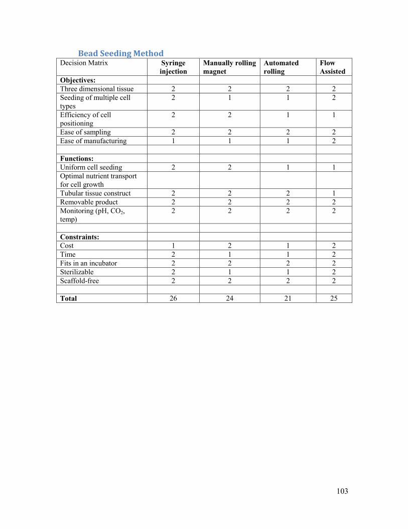
103
Bead Seeding Method Decision Matrix Syringe
injection Manually rolling magnet
Automated rolling
Flow Assisted
Objectives: Three dimensional tissue 2 2 2 2 Seeding of multiple cell types
2 1 1 2
Efficiency of cell positioning
2 2 1 1
Ease of sampling 2 2 2 2 Ease of manufacturing 1 1 1 2 Functions: Uniform cell seeding 2 2 1 1 Optimal nutrient transport for cell growth
Tubular tissue construct 2 2 2 1 Removable product 2 2 2 2 Monitoring (pH, CO2, temp)
2 2 2 2
Constraints: Cost 1 2 1 2 Time 2 1 1 2 Fits in an incubator 2 2 2 2 Sterilizable 2 1 1 2 Scaffold-free 2 2 2 2 Total 26 24 21 25

104
Flow System Decision Matrix Single
Reservoir Dual reservoir Semi-
permeable membrane split
Objectives: Three dimensional tissue 2 2 2 Seeding of multiple cell types
2 2 2
Efficiency of cell positioning 2 2 2 Ease of sampling 1 2 2 Ease of manufacturing 2 1 0 Functions: Uniform cell seeding 2 2 2 Optimal nutrient transport for cell growth
1 2 2
Tubular tissue construct 2 2 2 Removable product 2 2 2 Monitoring (pH, CO2, temp) 1 2 1 Constraints: Cost 2 1 1 Time 2 2 1 Fits in an incubator 2 1 1 Sterilizable 2 2 1 Scaffold-free 2 2 2 Total 27 29 25
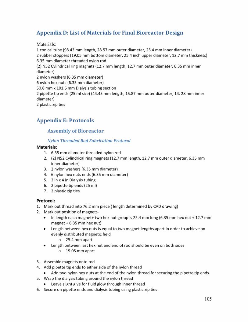
105
Appendix D: List of Materials for Final Bioreactor Design Materials: 1 conical tube (98.43 mm length, 28.57 mm outer diameter, 25.4 mm inner diameter) 2 rubber stoppers (19.05 mm bottom diameter, 25.4 inch upper diameter, 12.7 mm thickness) 6.35 mm diameter threaded nylon rod (2) N52 Cylindrical ring magnets (12.7 mm length, 12.7 mm outer diameter, 6.35 mm inner diameter) 2 nylon washers (6.35 mm diameter) 6 nylon hex nuts (6.35 mm diameter) 50.8 mm x 101.6 mm Dialysis tubing section 2 pipette tip ends (25 ml size) (44.45 mm length, 15.87 mm outer diameter, 14. 28 mm inner diameter) 2 plastic zip ties
Appendix E: Protocols
Assembly of Bioreactor
Nylon Threaded Rod Fabrication Protocol Materials:
1. 6.35 mm diameter threaded nylon rod 2. (2) N52 Cylindrical ring magnets (12.7 mm length, 12.7 mm outer diameter, 6.35 mm
inner diameter) 3. 2 nylon washers (6.35 mm diameter) 4. 6 nylon hex nuts ends (6.35 mm diameter) 5. 2 in x 4 in Dialysis tubing 6. 2 pipette tip ends (25 ml) 7. 2 plastic zip ties
Protocol: 1. Mark out thread into 76.2 mm piece ( length determined by CAD drawing) 2. Mark out position of magnets-
• In length each magnet+ two hex nut group is 25.4 mm long (6.35 mm hex nut + 12.7 mm magnet + 6.35 mm hex nut)
• Length between hex nuts is equal to two magnet lengths apart in order to achieve an evenly distributed magnetic field
o 25.4 mm apart • Length between last hex nut and end of rod should be even on both sides
o 19.05 mm apart
3. Assemble magnets onto rod 4. Add pipette tip ends to either side of the nylon thread
• Add two nylon hex nuts at the end of the nylon thread for securing the pipette tip ends 5. Wrap the dialysis tubing around the nylon thread
• Leave slight give for fluid glow through inner thread 6. Secure on pipette ends and dialysis tubing using plastic zip ties

106
Outer Bioreactor Fabrication Protocol Materials:
1. Nylon Threaded Rod (assembled with magnets) 2. 1 conical tube (98.43 in length, 28.57 in outer diameter, 25.4 mm inner diameter) 3. 2 rubber stoppers (19.05 mm bottom diameter, 25.4 mm upper diameter, 12.7 mm
thickness)
Protocol: 1. Drill 2 holes ( 12.7 mm in diameter) in rubber stoppers
o One in center, one 6.35 mm above (for media flow of inner and outer chamber of bioreactor)
2. Place 1 end of nylon thread (pipette end) inside the rubber stopper. 3. Fit rubber stopper and nylon tube into conical tubing end 4. Follow sterilization protocol (see Bioreactor Running and Sterilization)
Homogeneous Magnetic Field Analysis Materials:
1. 2 N52 neodymium rare earth magnets 2. 1 nylon washer 3. 1 nylon hex nut 4. Magnetic Paper (Made by Millipore) 5. 76.2 mm bar magnet (polarized on each end) 6. Camera
Procedure: 1. Assemble magnets together with nylon hex nut in between the two magnets. Attractive
forces between the magnets hold them together. 2. Take photo of assembly 3. Lay Magnetic Paper over the magnetic array. 4. Photograph changes in magnetic paper. 5. Clear magnetic paper using bar magnet by wiping the bar magnet over the magnetic
paper till the paper appears completely green again. 6. Repeat steps 1-5 using a nylon washer in place of the nylon hex nut. 7. Repeat steps 1-5 using nothing between the two magnets.
Diffusion Validation of Inner Rod Materials:
1. Assembled bioreactor (Nylon Threaded Rod inside conical tubing, closed with stoppers) 2. Tubing connection on one side of the bioreactor (center hole only) 3. 2 plugs

107
4. Liquid Syringe (100 mL) 5. Food Coloring Dye (Light and Dark) 6. About 120 mL water
Protocol: 1. Fill the outer bioreactor with light colored Food Coloring and Water. 2. Place end of tubing connectors in bucket or sink receptor 3. Plug the outer bioreactor connectors closed. 4. Flow dark food coloring water into center Nylon Threaded Rod using liquid syringe. 5. Record and photograph diffusion of dark colored dye into light colored dye (if any)
Growth Media Preparation
DMEM with 10% FBS, 1% Pen-Strep, 1% Glutamine, 1% NEAA, and 1% Sodium Pyruvate) Materials:
1. 500mL DMEM (1 bottle; Mediatech 15-017-CV) 2. 50mL Fetal Bovine Serum (FBS; PAA A15-201, Lot A20107-7003) 3. 5mL Penicillin-Streptomycin (P/S; Mediatech 30-002-CI) 4. 5mL Glutamine (Glut; Mediatech 25-015-CI) 5. 5mL MEM non-essential amino acid (NEAA; Mediatech 25-025-CI) 6. 5mL Sodium Pyruvate (sod. Pyruv; Mediatech 25-000-CI)
Procedure: 1. Heat DMEM and thaw aliquots of FBS, P/S, Glut, NEAA, and sod. Pyruv. in 37°C water
bath 2. Add all aliquots to DMEM 3. Label bottle with contents, initials, and date
Note: If making media in glass media bottle pour through a sterile bottle-top filter before adding to sterile bottle.
Rat Smooth Muscle Cell (RAMSC) Culture All cell manipulation was done in a sterile hood using meticulous aseptic technique. Media was pre-wormed to 37°C in water bath and confirmed that phenol red indicator dye in media and culture is an appropriate color (Yellow 6.5, Orange 7.0, Red 7.4, Pink 7.6). Cells were grown in a P-150 Petri dish with 20ml of growth media. Growth media was changed every 2-3 days and cell yields were an average of 8.8 x 10⁶ cells. The cells were incubated in 37°C, 5%CO2 humidified Incubator.

108
Cell Quantification In order to evaluate the quantity of cells that are needed to create a three-dimensional tissue, a few assays need to be performed. The first assay “Prior to Loading” will evaluate the quantity of cells that are being loaded into the bioreactor, while the “24 Hours Post Loading” assay will assess the quantity of cells which have not attached themselves to the dialysis tube. The last assay “Post Tissue Formation” (on the next page) will estimate the quantity of cells which exist in the entirety of the tissue formed.
Prior to Loading All cell manipulation should be done in a sterile hood using meticulous aseptic technique. Spray all surfaces with 70% ethanol to avoid contamination. Materials:
1. Two 5mL sterile pipette tips 2. Three 10mL sterile pipette tips 3. 100 µL pipette tip box 4. Pasture pipette tips (sterile) 5. 15mL tube 6. Trypan Blue 7. Media (DMEM WITH 10% FBS, 1% PEN-STREP, 1% GLUTAMINE, 1% NEAA, AND 1%
SODIUM PYRUVATE) 8. Trypsin 9. Hemocytometer 10. One Microfuge tube
Protocol:
1. Media should be pre-wormed to 37°C in water bath. Confirm that phenol red indicator dye in media and culture is an appropriate color (Yellow 6.5, Orange 7.0, Red 7.4, Pink 7.6)
2. Clean all materials with 70% ethanol and place in hood 3. Open P-150 Petri dish which is containing cells 4. Without touching the wall that the cells are adhered to, remove and dispose of growth
media using Pasture pipette tip 5. Add 10mL Trypsin 6. After 4 minutes add 20 mL normal growth media (The FBS will inactivate the residual
Trypsin) 7. Pipette cells up and down until it is released from the flask. 8. Remove cell mixture from flask and place in a 15mL conical tube 9. Centrifuge 50 mL tube at 100g for 5minutes 10. Remove supernatant using Pasture pipette tip 11. Suspend cell pellet with 20 ml of media 12. Transfer 40 µL of cell suspension to a microfuge tube 13. Add 40 µL of Trypan Blue solution (dilution factor =2)

109
14. Apply 20 µL of suspension to both chambers of hemocytometer by gently touching pipette tip to lower edge of overlying cover slip.
15. Count cells within 1 mm2 center square (5xS grid) of both chambers. Viable cells will be clear and non-viable cells will stain blue.
16. Cell counts can be calculated using the following formula: a. Average count per 1 mm2 square*dilution factor *104 = # cells/ml
17. Store media at 4°C between uses
Bead Fabrication Protocol developed by Christopher Lambert’s lab at WPI. Beads were prepared with the assistance of Anna Maziarz and Eftim Milkani.
Magnetic Fluid
Materials 1. 600ml beaker 2. 400ml beaker 3. Overhead mixer wrapped in Teflon tape 4. Water bath 5. Iron(II) Chloride Tetrahydrate 98% 6. Iron(III) Chloride Hexahydrate 97-102.0% 7. Dodecanoic acid (Lauric acid) 98% 8. Ammonia 9. Magnet
Protocol: 1. Add 2 grams of lauric acid in 200ml of .12 M Iron (II) Chloride Tetrahydrate and .24 M
Iron (III) Chloride hexahydrate to a 600ml beaker. 2. Place beaker in 50 deg C water bath at stir with overhead mixer at 1300rpm. 3. Add 40mL of 25% ammonia solution to the beaker using a pipette. 4. Continue stirring at 1300rpm for 30 minutes while maintain the temperature of the
water bath at 50 deg C. 5. Place the beaker over a magnet and add .5% ammonia solution until the precipitate
separates and decant the solution using a pipette. 6. Transfer the precipitate to a 400ml beaker with 100ml of 1g/L lauric acid solution. 7. Allow the solution to settle overnight and decant the clear liquid.
Agarose bead preparation Materials
1. Magnetic fluid 2. Ammonia 3. Soybean oil 4. Polysorbate 80

110
5. Overhead mixer 6. 400ml beaker 7. 150ml beaker 8. 50ml flask 9. Agarose 10. Acetone 11. Water bath 12. Sonicator 13. Microwave 14. 3ml syringe with 18G needle 15. Ice 16. Magnet
Protocol
1. Dilute 10ml of magnetic fluid in 10ml of DI water in a 50ml flask. 2. Bring the diluted magnetic fluid to a pH of 7 by adding .5% ammonia solution. 3. Sonicate the magnetic fluid for 30 minutes. 4. Add 180ml of soybean oil and 5.4g polysorbate to a 400ml beaker. 5. Place the beaker in a 90 deg C water bath and stir at 630rpm. 6. Add 10ml of 3% agarose solution to a 150ml beaker and heat in a microwave for 50
seconds. 7. Place the beaker of agarose solution and flask of magnetic fluid in the water bath for 20
seconds. 8. Quickly add the agarose solution to the flask of magnetic fluid while shaking to facilitate
mixing. 9. Return the flask to the water bath and load the syringe with the solution. 10. Using the syringe, transfer the solution drop-wise into the soybean oil mixture. 11. After adding all of the magnetic fluid, stir for an additional 10 minutes at 90 deg C. 12. Rapidly cool the water bath to 11 deg C by adding ice. 13. Continue stirring for 20 minutes at 630rpm. 14. Add acetone to the mixture until the oil phase turns clear and place the beaker over a
magnet. 15. Decant the solution and rinse beads with acetone. 16. Rinse and decant the beads three times with DI water. 17. Store the beads in DI water at 4 deg C.
Bead Sterilization
Materials 1. Agarose beads 2. Ethanol 3. DI Water 4. 40ml beaker
Procedure 1. Add the agarose beads to a 40 ml beaker. 2. Add 70% Ethanol in DI water and let soak for 10 minutes.

111
3. Place the beaker over a magnet and decant the solution. 4. Rinse the beads with DI water 3 times.
Bead Activation
Materials 1. 1-ethyl-3-(3-dimethylaminopropyl) carbodiimide (EDC) 2. N-Hydroxysuccinimide (NHS) 3. DI Water 4. Shaker 5. Aluminum foil 6. 10ml syringe with 2um filter 7. 20ml beaker 8. Sterile agarose beads
Protocol 1. Filter 5ml of .1M EDC with .02M NHS solution using the 2um syringe filter. 2. Suspend the agarose beads in the EDC/NHS solution in a 20ml beaker and wrap in
aluminum foil. 3. Place on a shaker for 30 minutes at room temperature. 4. Rinse the beads three times with DI water.
Collagen coating Materials
1. Sterilized and activated agarose beads 2. Collagen 3. Sodium carbonate 4. Sodium bicarbonate 5. Magnet 6. PBS
Protocol 1. Combine .1M sodium carbonate with .1M sodium bicarbonate to form a 9.6pH buffer
solution. 2. Combine 1ul of collagen with 1ul of buffer solution. 3. Store mixture at 4 deg C overnight. 4. Rinse the beads with PBS three times and store in PBS solution.
Bioreactor Tissue Culture Protocol All cell manipulation should be done in a sterile hood using meticulous aseptic technique. Spray all surfaces with 70% ethanol to avoid contamination. Materials
1. One P-150 Petri dish with cells 2. Beads in 15ml conical tube 3. Petri dish

112
4. Media (DMEM WITH 10%FBS, 1%PEN-STREP, 1%GLUTAMINE, 1%NEAA, AND 1%SODIUM PYRUVATE)
5. Bioreactor 6. Media Box 7. Pump 8. Tubing 9. 70% Ethanol 10. Sterile 1X PBS
Protocol: Day 1
1. Clean all materials with 70% ethanol and place in hood 2. Follow the “Assembly of Bioreactor” protocol 3. Clean bioreactor, media boxes, and tubing with 70% Ethanol 4. Run 1X PBS through bioreactor, media boxes, and tubing. 5. Repeat steps 2 and 3, twice 6. Connect the bioreactor to media boxes using the tubing 7. Fill each media box with 110ml of media 8. Place bioreactor and media boxes in the incubator 9. Run tubing through peristaltic pump 10. Turn pump on and let the bioreactor fill with media 11. Take out P-150 Petri with cells and follow the “Prior to Loading” assay 12. Take 15 x 106 cells out of the 50ml conical tube and re-suspend them in 15ml conical
tube which contains the beads. 13. Expose cells to the beads for a period of 2 hours 14. Sterilize injection port of the bioreactor (use 70% ethanol) 15. Insert new mixture of beads and cells into the bioreactor through injection valves using
a syringe.
Removal of Tissue Materials
1. Bioreactor 2. Media Box 3. Peristaltic pump 4. Silicone tubing 5. Formalin 6. 70% Ethanol 7. 50ml Conical tube
Protocol:
1. Clean all materials with 70% ethanol and place in hood 2. Take device out of incubator and place in sterile hood

113
3. Take 50ml conical tube and fill it with Formalin 4. Disconnect the bioreactor from the media box 5. Without touching the dialysis tube that the cells are adhered to, remove growth media
using a Pasture pipette tip 6. Takeout threaded nylon rod 7. Gently pull the newly formed tissue off the threaded nylon rod 8. Place dialysis tube in the 50ml conical tube for a period of 1 hour 9. After an hour, replace Formalin with 70% Ethanol
Masson Trichrome Stain Procedure
Histology testing and protocol was performed and written by Sharron Shaw Masson Trichrome Reagents: Bouin’s Solution (Sigma HT10-1-128) Weigert Iron Hematoxylin Solution A (Sigma HT107-500ml) Solution B (Sigma HT109-500ml)
Working Solution: Mix Equal parts of solutions A and B. Biebrich Scarlet-Acid Fuchsin Solution 1% Biebrich Scarlet Biebrich Scarlet 2gm Distilled water 200ml 1% Acid Fuchsin Acid Fuchsin 1gm Distilled Water 100ml Working Solution: 1% Biebrich Scarlet 180ml 1% Acid Fuchsin 20ml Glacial Acetic Acid 2ml Phosphomolybdic/Phosphotungstic Acid Solution Working Solution: Phosphomolybdic Acid Solution (HT153-250ml) 1 part Phosphotungstic Acid Solution (HT152-250ml) 1 part Distilled water 2 parts 1% Aniline Blue Solution Aniline Blue 5gm Glacial Acetic Acid 4ml Distilled Water 200ml 1 % Acetic Acid Solution Glacial acetic acid 1 mL
Distilled Water 99mL Paraffin Procedure:
1. Dehydrate in Xylene I for 3 minutes.

114
2. Dehydrate in Xylene II for 3 minutes. 3. Dehydrate in Xylene III for 3 minutes. 4. Dehydrate in 100% ETOH for 3 minutes. 5. Dehydrate in 100% ETOH for 3 minutes. 6. Dehydrate in 95% ETOH for 1 minute. 7. Dehydrate in 70% ETOH for 1 minute. 8. Rinse slides well in distilled water. 9. Mordant the sections in Bouin solution for 1 hour at 56 C. 10. Remove slides from oven, allow to cool, wash in running water until the yellow color
disappears. 11. Stain sections in Weigert hematoxylin for 10 minutes. 12. Wash in warm running tap water for 10 minutes. 13. Stain sections in Biebrich scarlet-acid fuchsin solution for 3 minutes. 14. Rinse in distilled water. 15. Place slides in Phosphomoybdic/Phosphotungstic acid solution for 15 minutes. Discard
this solution. 16. Stain sections in aniline blue solution for 5 minutes. 17. Rinse slides in distilled water. 18. Place slides in 1% acetic acid solution for 5 minutes. Discard this solution. 19. Rinse in several changes of tap water. 20. Dehydrate through graded alcohols, clear in two changes of xylene and mount with
cytoseal.
Results: Nuclei Black Cytoplasm, Keratin, Muscle fibers Red Collagen and Mucus Blue
Hematoxylin and Eosin Staining Procedure Histology testing and protocol was performed and written by Sharron Shaw Procedure 1. Xylene----------------------------------------------------------------------3 Minutes 2. Xylene----------------------------------------------------------------------3 Minutes 3. Xylene----------------------------------------------------------------------3 Minutes 4. 100% ETOH---------------------------------------------------------------3 Minutes 5. 100% ETOH---------------------------------------------------------------3 Minutes 6. 95% ETOH-----------------------------------------------------------------1 Minute 7. 70% ETOH-----------------------------------------------------------------1 Minute 8. Rinse in running H2O-----------------------------------------------------Until clear 9. Harris Hematoxylin--------------------------------------------------------5 Minutes 10. Rinse in running H2O----------------------------------------------------Until clear

115
11. Differentiate sections in 1% HCL mixed in 70% ETOH. -----------2-3 quick dips. (.25 ml HCL to 100 ml of 70% ETOH) 12. Rinse in running H2O----------------------------------------------------30 Seconds 13. Blue sections in ammonia solution-------------------------------------1 Minute. (3ml of 28% ammonia hydroxide in 1L tap water.) 14. Rinse in running warm H2O--------------------------------------------5 Minutes 15. 95% FTOH----------------------------------------------------------------30 seconds 16. Counterstain in Eosin-Y-------------------------------------------------1 Minute 17. 70% ETOH----------------------------------------------------------------30 Seconds 18. 95% ETOH----------------------------------------------------------------30 Seconds 19. 95% ETOH----------------------------------------------------------------30 Seconds 20. 100% ETOH--------------------------------------------------------------1 Minute 21. 100% ETOH--------------------------------------------------------------1 Minute 22. 100 % ETOH-------------------------------------------------------------1 Minute 23. Xylene---------------------------------------------------------------------1 Minute 24. Xylene---------------------------------------------------------------------1 Minute 25. Xylene---------------------------------------------------------------------1 Minute Coverslip slides using synthetic mounting medium. Results Nuclei-------------- Blue Cytoplasm----------Pink Blood----------------Red
Picrosirius Red Protocol
Histology testing and protocol was performed and written by Sharron Shaw Reagents: 0.1% Sirius Red Solution Direct Red 80 (Aldrich 36,554-8) 0.25gm Picric Acid (Sigma P6744-1GA) 250ml Procedure:
1. Deparaffin in Xylene I clearing agent for 3 minutes. 2. Deparaffin in Xylene II clearing agent for 3 minutes. 3. Deparaffin in Xylene III clearing agent for 3 minutes. 4. Hydrate in 100% ETOH for 3 minutes. 5. Hydrate in 100% ETOH for 3 minutes. 6. Hydrate in 95% ETOH for 1 minute. 7. Hydrate in 95% ETOH for 3 minutes. 8. Hydrate in 70% ETOH for 3 minutes. 9. Rinse slides well in water. 10. Place in Picrosirius solution for 30 minutes. 11. Dehydrate in 80% ETOH for 1 minute.

116
12. Dehydrate in 95% ETOH for 1 minute. 13. Dehydrate in 95% ETOH for 1 minute. 14. Dehydrate in 100% ETOH for 5 minutes. 15. Dehydrate in 100% ETOH for 5 minutes. 16. Dehydrate in 100% ETOH for 10 minutes. 17. Place in Xylene I clearing agent for 3 minutes. 18. Place in Xylene II clearing agent for 3 minutes. 19. Place in Xylene III clearing agent for 3 minutes. 20. Mount with mounting media.
Results: Collagenous fibers Red Other tissue fibers Green
Appendix F: Calculations
Bead Concentration Approximation Assuming average bead diameter of 100μm. 1 cm3 = 1 ml
Number of beads per cm3 = � 1𝑐𝑐𝑐𝑐𝐵𝐵𝐵𝐵𝐵𝐵𝐵𝐵 𝐵𝐵𝑑𝑑𝐵𝐵𝑐𝑐𝐵𝐵𝑑𝑑𝐵𝐵𝑑𝑑
�3= 1 × 10⁶ beads/cm3 = 1 × 10⁶ beads/ml
Bead Seeding Calculations
Dimensions of central rod: 16mm diameter, 43.7mm length Surface area of rod: 43.7(𝑐𝑐𝑐𝑐) 𝑋𝑋 16(𝑐𝑐𝑐𝑐) 𝑋𝑋 𝛱𝛱 Assuming bead diameter of 100μm: Bead cross-sectional area = (.1(𝑐𝑐𝑐𝑐 )
2)2 𝑋𝑋 𝛱𝛱
Number of beads to cover central rod = 𝑆𝑆𝑆𝑆𝑑𝑑𝑆𝑆𝐵𝐵𝑐𝑐𝐵𝐵 𝐵𝐵𝑑𝑑𝐵𝐵𝐵𝐵 𝑜𝑜𝑆𝑆 𝑑𝑑𝑜𝑜𝐵𝐵
𝐵𝐵𝐵𝐵𝐵𝐵𝐵𝐵 𝑐𝑐𝑑𝑑𝑜𝑜𝑐𝑐𝑐𝑐 −𝑐𝑐𝐵𝐵𝑐𝑐𝑑𝑑𝑑𝑑𝑜𝑜𝑠𝑠𝐵𝐵𝑠𝑠 𝐵𝐵𝑑𝑑𝐵𝐵𝐵𝐵= 43.7𝑐𝑐𝑐𝑐 𝑋𝑋 16𝑐𝑐𝑐𝑐 𝑋𝑋 𝛱𝛱
(.1(𝑐𝑐𝑐𝑐 )2 )2 𝑋𝑋 𝛱𝛱
=
= 279,680 beads Settle bead volume = 279,680 𝑏𝑏𝐵𝐵𝐵𝐵𝐵𝐵𝑐𝑐
1 𝑋𝑋 106 𝑏𝑏𝐵𝐵𝐵𝐵𝐵𝐵𝑐𝑐 /𝑐𝑐𝑠𝑠 ≈ .28ml
Bioreactor Media Flow
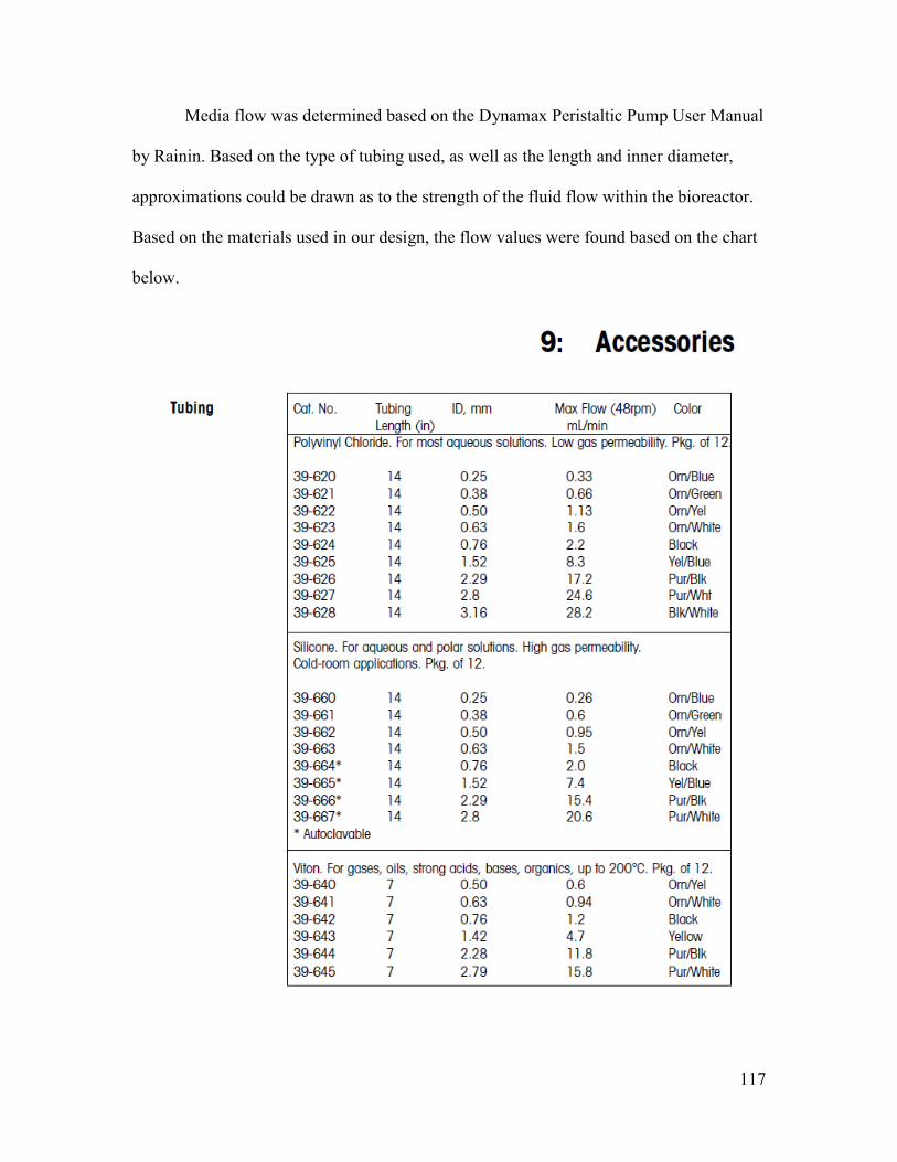
117
Media flow was determined based on the Dynamax Peristaltic Pump User Manual
by Rainin. Based on the type of tubing used, as well as the length and inner diameter,
approximations could be drawn as to the strength of the fluid flow within the bioreactor.
Based on the materials used in our design, the flow values were found based on the chart
below.

118
Cost of Beads Materials
Beads + Magnetic fluid Material Quantity Cost ($)
Lauric acid – Alfa 2.1g 0.05796 Iron(II) Chloride Tetrahydrate – Alfa 4.77g 0.63918 Iron(III) Chloride hexahydrate – Alfa 12.97g 1.395572 Soybean Oil – Spectrum 175ml 8.640625 Polysorbate 80 – JT Baker 5.4g 0.63828 SeaKem LE Agarose – Lonza .3g 0.378
Bead Activation Material Quantity Cost($)
1-Ethyl-3-(3-dimethylaminopropyl)carbodiimide .019g 0.10393 N-hydroxysuccinimide .023g 0.02852
Collagen Coating Material Quantity Cost ($)
Collagen - Spectrum .1g 12 Sodium Bicarbonate .01g 0.07587253 Sodium Carbonate .01g 0.21645022
Total: $24.17 Approximate yield = 2ml of beads
MQP Budget
Item Cost (in Dollars) Notebook 19 Nylon Rod (.25") 4.6 Nylon Rod (.112") 6.75 Nylon Nuts (.25") 2.95 Nylon Nuts (.112") 3.95 Nylon Washers (.25") 1.32 Dialysis Tubing (2) 11.7 Magnets (.25) 36 Magnets (.112) 21 Teflon Tape 0.97 Silicon Caulking 5.89 Rubber Stoppers 5.5 Soybean Oil 66.5 Polysorbate 61.45 Agarose 89.13 Comercial Beads 70 Silicon Tubing (50 ft) 30 Total Spent 436.71 Budget Remaining 30.29