magnetism - university of florida · 9 paramagnetism atoms/molecules in solids/liquids with odd no...
TRANSCRIPT

1
A. K. Majumdar
Indian Institute of Science Education & Research Kolkata, India
Indian Institute of Technology, Kanpur, India(1972-2006)
University of Florida, Gainesville, July 11-14, 2011
Magnetism
2
Plan of the Talk
History of MagnetismDiamagnetismParamagnetism
FerromagnetismWeiss’ “molecular field” theoryHeisenberg’s theory Bloch’s spin-wave theoryBand theory of ferromagnetism
Spin glass (1972)
R & D in Magnetic Materials after 1973Magnetoresistance (MR)Ordinary or normal magnetoresistance (OMR)Anisotropic magnetoresistance (AMR) in a ferromagnetGiant magnetoresistance (GMR)
Hall effect in ferromagnetsFe-Cr multilayers: GMR and Hall effect
ApplicationsNano-magnetismSuperparamagnetismExamples: Ni nano/TiNExchange bias Tunnel magnetoresistance (TMR)Colossal magnetoresistance (CMR)
Plan of the lectures
3
The study of magnetism started with the discovery of the Lodestone (or Magnetite Fe 3O4 ) around 500-800 B.C. in Greece & China.
Lodestones attract pieces of iron and the attraction can only be stopped by placing between them an iron plate, which acts as a Magnetic Shield.
The directional property of the Lodestone was utilized to design “Compass”, which was invented around 100 A.D. in China.
Theoretical understanding of magnetism came only in the 19th
century along with some basic applications .
History of Magnetism
4
Diamagnetism The weakest manifestation of magnetism is Diamagnetism ⇒⇒⇒⇒
Change of orbital moment of electrons due to appli ed magnetic field.
The relevant parameter which quantifies the strength of magnetism is the Magnetic Susceptibility, χχχχ, which is defined as
χ = LtH→0 (dM/dH).
Diamagnetism arises from two basic laws of Physics, viz.,Faraday’s law & Lenz’s law:An electron moves around a nucleus in a circle of radius, r.A magnetic field H is applied. The induced electric field, E(r),generated during the change is
E(r) 2πr = -d/dt (H π r2)/c or, E(r) = - (r/2c) dH/dt.
Diamagnetism

5
This E(r) produces a force & hence a torque = – e E(r) r = dL/dt = (e r2 /2c) dH/dt, (e > 0).
The extra ∆L(L was already there for the orbital motion) due to the turning of the field = (e r2 /2c) H.The corresponding moment µ= - (e/2mc) ∆L = - (e2 r2 /4mc2) H, r2 = x 2 + y2.
For N atoms per unit volume with atomic no. Z, the Magnetic Susceptibility
χχχχ = - (Ne2Z<r2>av ) /6mc2.
QM treatment also produces the same answer!!!
χ is negative ≈ - 10-6 in cgs units in the case of typical diamagnetic materials. In
SI units it is - 4π x 10-6.
Diamagnetism

6
Diamagnetism
QM treatment
The Hamiltonian of a charged particle in a magnetic field B is
H = (p – eA/c)2/2m + eφ, A = vector pot, φ = scalar pot, valid for both classical & QM.
K.E. is not dependent on B, so it is unlikely that A enters H. But
p = p kin + pfield = mV + eA/c (Kittel, App. G, P: 654)
& K.E. = (mV)2 /2m = (p – eA/c)2/2m, where B = ∇∇∇∇ X A.
So, B-field-dependent part of H is ieh/4πmc[∇∇∇∇. A+ A. ∇∇∇∇ ] + e2 A2/2mc2.(1)

7
Diamagnetism
QM treatment
χ = LtH→0 (dM/dH) = - (Ne2Z<r2>av )/6mc2 independent of T.
M = - ∂E’/∂B = - (Ne2Z<r2>av )/6mc2 B for N atoms/volume with atomic no. Z.
Since B = H for non-magnetic materials
If B is uniform and II z-axis, AX = - ½ y B, AY = ½ x B, and AZ = 0.
So, (1) becomes H =(e/2mc) B [ih/2π(x ∂/∂y - y ∂/∂x)] + e2B2/8mc2(x2 + y2).↓ ↓
LZ ⇒ Orbital PM; E’ = e2B2/12mc2 <r2>by 1st order
perturbation theory.
8
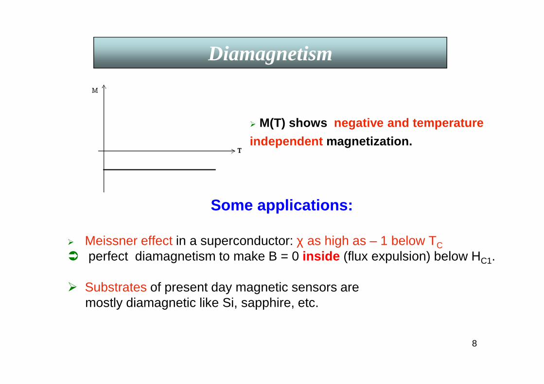
Some applications:
Meissner effect in a superconductor: χ as high as – 1 below TC perfect diamagnetism to make B = 0 inside (flux expulsion) below HC1.
Substrates of present day magnetic sensors are mostly diamagnetic like Si, sapphire, etc.
Diamagnetism
M(T) shows negative and temperature
independent magnetization.

9
ParamagnetismAtoms/molecules in solids/liquids with odd no of electrons(S≠0):free Na atoms with partly filled inner shells, compounds likemolecular oxygen and organic biradicals, metals (Pauli), etc. contribute to electron paramagnetism.
Free atoms/ions with partly filled inner shells, e.g., Mn2+, Gd3+, U 4+
show ionic paramagnetism.
A collection of magnetic moments, m, interact with external magnetic field H:
Interaction energy U = - m . H. Magnetization results from the orientation of the magnetic moments but
thermal disorders disturb this orientation.
Paramagnetism
10
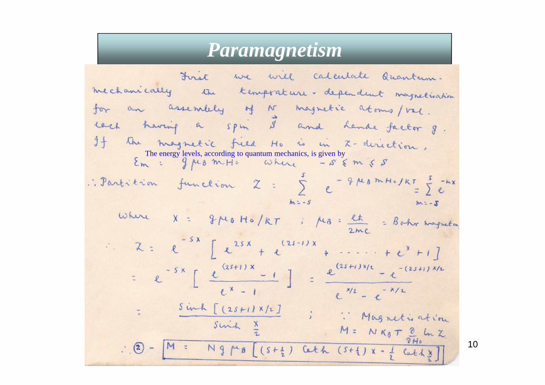
Paramagnetism
The energy levels, according to quantum mechanics, is given by
11
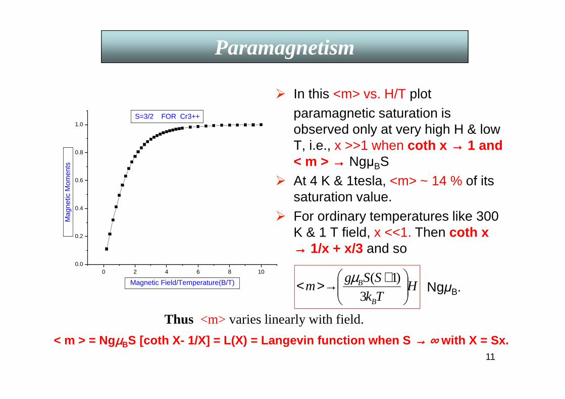
In this <m> vs. H/T plotparamagnetic saturation is observed only at very high H & low T, i.e., x >>1 when coth x →→→→ 1 and < m > →→→→ NgµBS
At 4 K & 1tesla, <m> ~ 14 % of its saturation value.
For ordinary temperatures like 300 K & 1 T field, x <<1. Then coth x→→→→ 1/x + x/3 and so
NgµB.
Paramagnetism
0 2 4 6 8 100.0
0.2
0.4
0.6
0.8
1.0S=3/2 FOR Cr3++
Mag
netic
Mom
ents
Magnetic Field/Temperature(B/T) HTk
SSgm
B
B
+>→<3
)1(µ
Thus <m> varies linearly with field.
< m > = NgµµµµBS [coth X- 1/X] = L(X) = Langevin function when S →→→→ ∞∞∞∞ with X = Sx.

12
So the Magnetic Susceptibility, χχχχ at temperature T isχχχχ = ( N g2 µµµµB
2 S(S+1)/3kB)*1/T= C/T,
where N= No. of ions/vol, g is the Lande factor, µµµµB is the Bohr magneton and C is the Curie constant. This is the famous Curie law for paramagnets.
Some applications:To obtain temperatures lower than 4.2 K, paramagnetic salts like,
CeMgNO3 , CrKSO4, etc., are kept in an isothermal 4.2 K bath & a field of, say, 1 T applied.
>>> Entropy of the system decreases & heat goes out. Finally the magnetic field is removed adiabatically. >>> Lattice temperature drops to mK range.
Similarly microkelvin is obtained using nuclear dem agnetization.
Paramagnetism
13
Paramagnetism
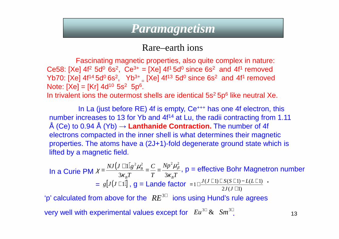
Fascinating magnetic properties, also quite complex in nature:Ce58: [Xe] 4f2 5d0 6s2, Ce3+ = [Xe] 4f1 5d0 since 6s2 and 4f1 removedYb70: [Xe] 4f14 5d0 6s2, Yb3+
= [Xe] 4f13 5d0 since 6s2 and 4f1 removedNote: [Xe] = [Kr] 4d10 5s2 5p6.In trivalent ions the outermost shells are identical 5s2 5p6 like neutral Xe.
In La (just before RE) 4f is empty, Ce+++ has one 4f electron, this number increases to 13 for Yb and 4f14 at Lu, the radii contracting from 1.11 Å (Ce) to 0.94 Å (Yb) → Lanthanide Contraction. The number of 4f electrons compacted in the inner shell is what determines their magnetic properties. The atoms have a (2J+1)-fold degenerate ground state which is lifted by a magnetic field.
Rare–earth ions
In a Curie PM
=
( )T
Np
T
C
T
gJNJ
BB
B
κµ
κµχ β
33
12222
==+= , p = effective Bohr Magnetron number
.( )[ ]1+JJg)1(2
)1()1()1(1
++−++++=
JJ
LLSSJJ, g = Lande factor
‘p’ calculated from above for the +3RE ions using Hund’s rule agrees
very well with experimental values except for &3+Eu +3Sm .
14
Paramagnetism
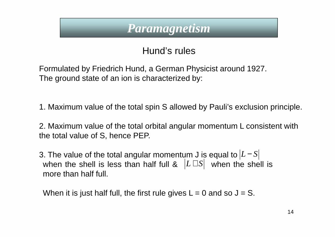
Hund’s rules
SL −SL +
Formulated by Friedrich Hund, a German Physicist around 1927.The ground state of an ion is characterized by:
1. Maximum value of the total spin S allowed by Pauli’s exclusion principle.
2. Maximum value of the total orbital angular momentum L consistent with the total value of S, hence PEP.
3. The value of the total angular momentum J is equal towhen the shell is less than half full & when the shell ismore than half full.
When it is just half full, the first rule gives L = 0 and so J = S.
15
Paramagnetism
Explanation of 2nd rule: Best approached by model calculations.
electrons. Therefore, all electrons tend to become
are separated more and hence have less positive P.E. than for↑↑
Explanation 1st rule: It’s origin is Pauli’s exclusion principle and Coulomb repulsion between electrons.
↑↓ ↑↑ giving maximum S.
+2Mn Mn: 25 43 sd +2Mn 53dExample of rules 1 & 2: , (half- filled 3d sub shell).
All 5 spins can be to each other if each electron occupies a differentorbital and there are exactly 5 orbitals characterized by orbital angularquantum nos. ml = -2, -1, 0, 1, 2. One expects S = 5/2 and so ∑ ml = 0.Therefore L is 0 as observed.

16
Paramagnetism
Explanation of 3rd rule:Consequence of the sign of the spin-orbit interaction. For a singleelectron, energy is lowest when S is antiparallel to L (L.S = - ve). Butthe low energy pairs ml and ms are progressively used up as one addselectrons to the shell. By PEP, when the shell is more than half full thestate of lowest energy necessarily has the S L.
Examples of rule 3:Ce3+ = [Xe] 4f1 5s2 5p6 since 6s2 and 4f1 removed. Similarly Pr3+ = [Xe]4f2 5s2 5p6. Nd3+, Pm3+, Sm3+, Eu3+,Gd3+,Tb3+, Dy3+, Ho3+,Er3+ ,Tm3+,Yb3+
have 4f3 to 4f13. Take Ce3+: It has one 4f electron, an f electron has l = 3,s = ½, 4f shell is less than half full (full shell has 14 electrons), by thirdrule = J = L – S = L - 1/2 = 5/2.
Js L12 +
2/52F
+3Pr
Spectroscopic notation ⇒⇒⇒⇒ [L = 0, 1, 2, 3, 4, 5, 6 are S, P, D, F, G, H, I].
has 2 ‘4f’ electrons: s = 1, l = 3. Both cannot have ml = 3 (PEP),so max. L is not 6 but 5. J = L – S = 5 -1 = 4. ⇒⇒⇒⇒ 3H4
17
Paramagnetism
Exactly ½ full 4f shell: : has 7 ’4f’ electrons; s = 7/2, L = 0, J = 7/2
+3Nd2/9
4I
+3Pm 45I
has 3 ‘4f’ electrons: s = 3/2, L = 6 , J = 6 - 3/2 = 9/2⇒
has 4 ‘4f’ electrons: s = 2, L = 6, J = L - S = 4 ⇒
+3Gd
2/78S⇒
+3Ho ↑
↓ 85I
4f shell is more than half full: has 10 ‘4f’ electrons: 7 will be ,
3 will be . S = 2, L = 6 [3 2 1 0 -1 -2 -3] ; J = 6 + 2 = 8 ⇒ and so on.
Note: 4f shell is well within the inner core (localized) surrounded by 5s2, 5p6, and6s2 & so almost unaffected by crystal field (CF).
3d transition element ions3d transition element ions, being in the outermost shell, are affected by strongly inhomogeneous electric field, called the “crystal field” (CF)of neighboring ions in a real crystal. L-S coupling breaks, so states are not specified by J. (2L + 1) degenerate levels for the free ions may split by the CF and L is often quenched.“p” calculated from J gives total disagreement with e xperiments.

18
Paramagnetism
Details: If E is towards a fixed nucleus, classically all LX, LY, LZare constants (fixed plane for a central force). In QM LZ & L2 are constants of motion but in a non-central field (as in a crystal) the orbital plane is not fixed & the components of L are not constants & may be even zero on the average. If <LZ> = 0, L is said to be quenched.
3d transition element ions (Contd.)
In an orthorhombic crystal, say, the neighboring charges produce about the nucleus a potential V = Ax2 + By2 – (A + B)z2 satisfying Laplace equation & the crystal symmetry. For L =1, the orbital moment of all 3 energy levels have <LZ> = 0. The CF splits the degenerate level with separation >> what the B-field does. For cubic symmetry, there is no quadratic term in V & so p electron levels will remain triply degenerate unless there is a spontaneous displacement of the magnetic ion, called Jahn-Teller effect , which lifts the degeneracy and lowers its energy.Mn3+ has a large JT effect in manganites which produces Colossal Magnetoresistance (CMR).
For details see C. Kittel, ISSP (7 th Ed.) P. 425-429; Ashcroft & Mermin, P. 655-659.

19
ParamagnetismPauli paramagnetism in metalsParamagnetic susceptibility of a free electron gas: There is a
change in the occupation number of up & down spin electrons even in a non-magnetic metal when a magnetic field B is applied.
The magnetization is given by ( T << TF )
M = µ (Nup - Ndown) = µ2 D ( εF ) B, D ( εF ) = 3N/2εF.
∴∴∴∴ χ = 3 N µ2 / 2εF , independent of temperature,
where D ( εF ) = Density of states at the Fermi level εF.
20
Any theory of ferromagnetism has to explain:
i) Existence of spontaneous magnetization M below TC(Paramagnetic to ferromagnetic transition temperature).
ii) Below TC, a small H0 produces MS from M ~ 0 at H = 0.
There are three major theories on ferromagnetism:
1. Weiss’ “molecular field” theory
2. Heisenberg’s theory
3. Bloch’s spin-wave theory (T << Tc).
Ferromagnetism
21
Weiss proposed that:i) Below TC spontaneously magnetized domains, randomly oriented give M ~ 0 at H=0. A small H0 produces domain growth with M || H0.ii) A very strong “molecular field”, HE of unknown origin aligns the atomic moments within a domain.
Taking alignment energy ~ thermal energy below Tc,For Fe: HE = kBTC / µ ~ 107 gauss ~ 103 T !!!
Ed-d ~ [µ1. µ2 - (µ1.r12) (µ2.r12)]/4πε0r3.
Classical dipole-dipole interaction gives a field of ~ 0.1 T only& is anisotropic but ferromagnetic anisotropy is only a secondorder effect. So ???
Weiss postulated that HE = λM, where λ is the molecular field parameter and M is the saturation magnetization.
Ferromagnetism
Weiss’ “molecular field” theory
22
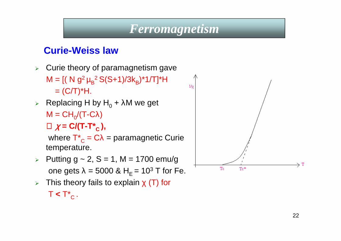
Curie-Weiss law
Curie theory of paramagnetism gaveM = [( N g2 µB
2 S(S+1)/3kB)*1/T]*H= (C/T)*H.
Replacing H by H0 + λM we getM = CH0/(T-Cλ)∴∴∴∴ χχχχ = C/(T-T*C ),where T*C = Cλ = paramagnetic Curie
temperature. Putting g ~ 2, S = 1, M = 1700 emu/g
one gets λ = 5000 & HE = 103 T for Fe. This theory fails to explain χ (T) for
T < T*C .
Ferromagnetism
23
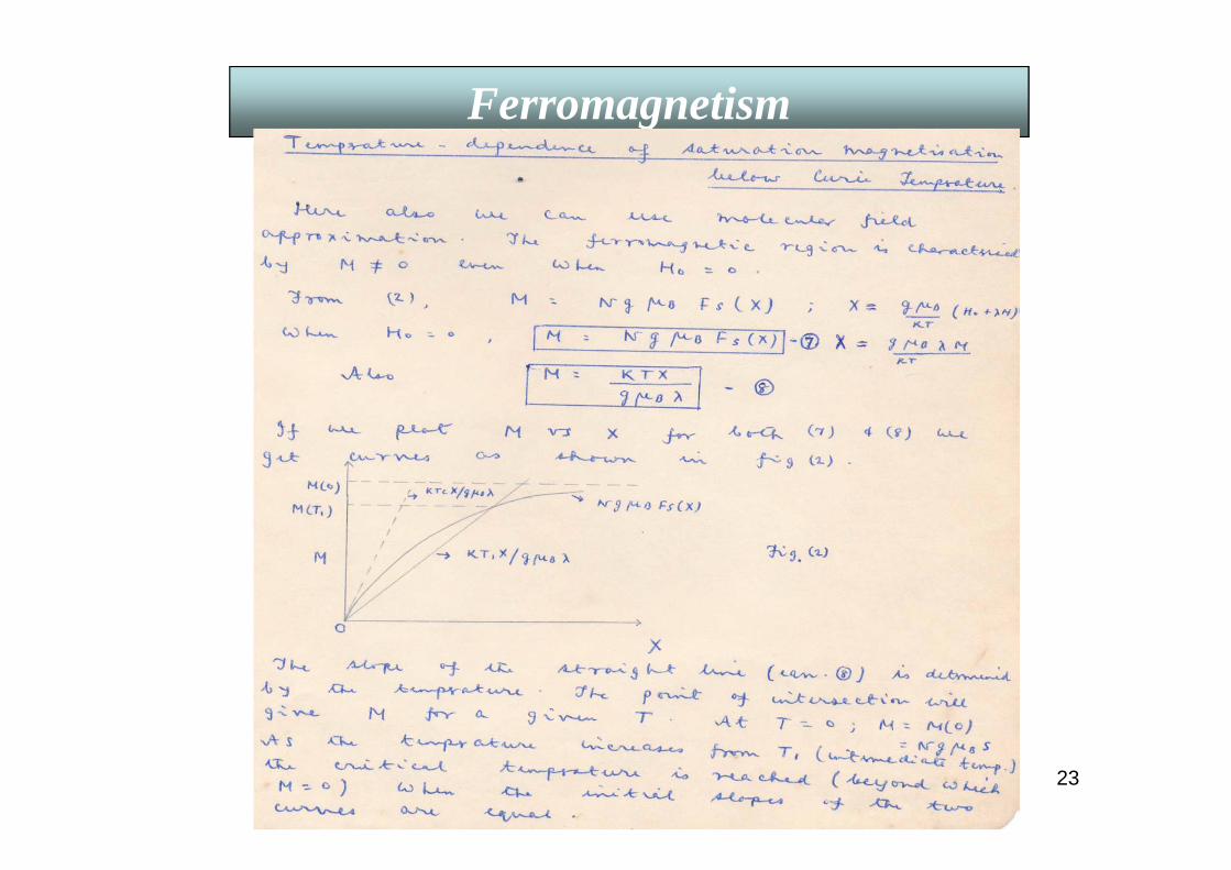
Ferromagnetism

24
Ferromagnetism

25
Ferromagnetism
26
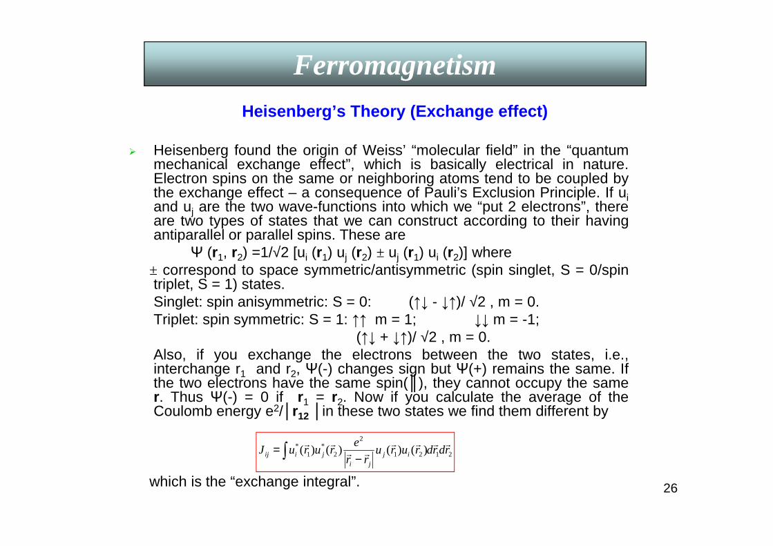
Heisenberg’s Theory (Exchange effect)
2121
2
2*
1* )()()()( rdrdruru
rr
eruruJ ij
ji
jiij
rrrrrr
rr
∫ −=
Ferromagnetism
Heisenberg found the origin of Weiss’ “molecular field” in the “quantummechanical exchange effect”, which is basically electrical in nature.Electron spins on the same or neighboring atoms tend to be coupled bythe exchange effect – a consequence of Pauli’s Exclusion Principle. If uiand uj are the two wave-functions into which we “put 2 electrons”, thereare two types of states that we can construct according to their havingantiparallel or parallel spins. These are
Ψ (r1, r2) =1/√2 [ui (r1) uj (r2) ± uj (r1) ui (r2)] where± correspond to space symmetric/antisymmetric (spin singlet, S = 0/spintriplet, S = 1) states.Singlet: spin anisymmetric: S = 0: (↑↓ - ↓↑)/ √2 , m = 0.Triplet: spin symmetric: S = 1: ↑↑ m = 1; ↓↓ m = -1;
(↑↓ + ↓↑)/ √2 , m = 0.Also, if you exchange the electrons between the two states, i.e.,interchange r1 and r2, Ψ(-) changes sign but Ψ(+) remains the same. Ifthe two electrons have the same spin(), they cannot occupy the samer. Thus Ψ(-) = 0 if r1 = r2. Now if you calculate the average of theCoulomb energy e2/r12 in these two states we find them different by
which is the “exchange integral”.

27
Ferromagnetism

28
Ferromagnetism
29
Ferromagnetism

30
Ferromagnetism
Assuming nearest neighbour exchange interaction, Jij = J & Si Swe get the Hamiltonian
H = - gµBH0NS - ½ 2JNZ(S)2,
where Z = no. of N.N.’s; N = no. of atoms/vol.
Simple algebra gives, replacing H0 by H0 + HE (= λM), using TC = C λ,
C= N g2 µB2 S(S+1)/3kB & M = NgµBS in H = -M(H0 + ½ HE ),
λλλλ = (2JZ/Ng2µµµµB2) & J = (3kBTC/2ZS(S+1))
~ 1.2 x 10⁻² eV for Fe with S = 1.
Taking S = ½ , one gets (kBTC/ ZJ) = 0.5 from mean-field theory
= 0.325 from Rushbrooke & Wood theory.
j
jiji
iiji
ZiB SSJSHgH
rr
∑∑≠
−−=,
0 .2µ
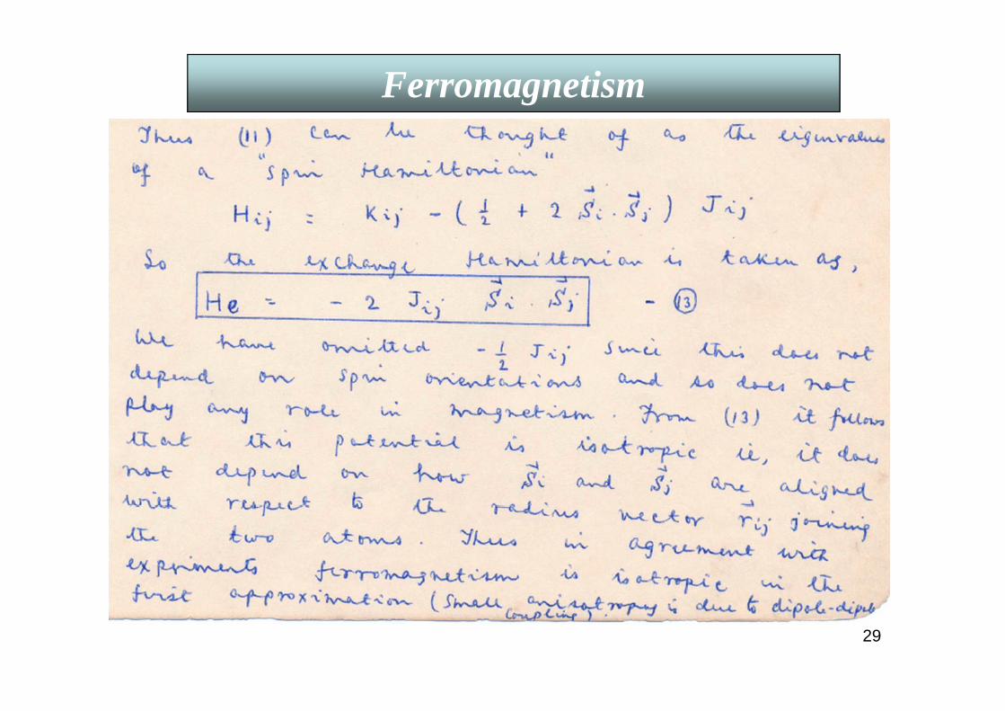
jiije SSJHrr
.2−=
In the presence of a field Ho, the Hamiltonian becomes
Heisenberg gave the exchange Hamiltonian the formwhich is isotropic.

31
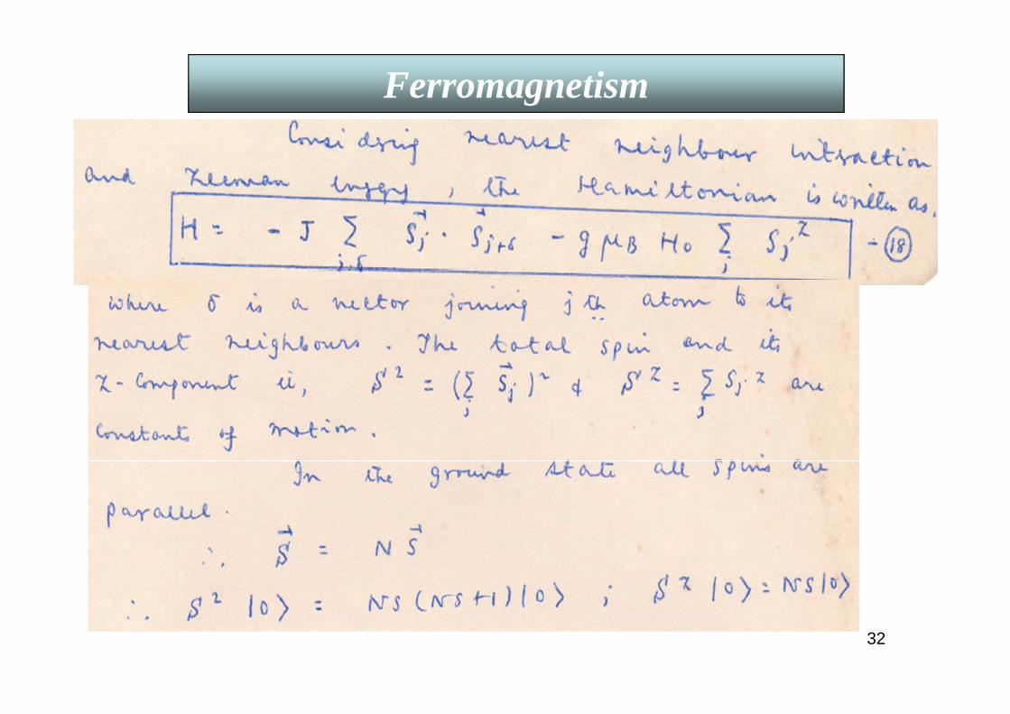
Bloch’s Spin-wave Theory (T <<Tc)
In the ground state of a FM (at 0 K) the atoms at different lattice sites have their maximum z-component of spin, Sj
z = S.As T increases the system is excited out of its ground state giving rise to sinusoidal “Spin Waves”, as shown below.
Ferromagnetism
The amplitude of this wave at jth site is proportional to S-Sjz.
The energy of these spin waves is quantized and the energy quantum is called a “magnon”.
32
Ferromagnetism
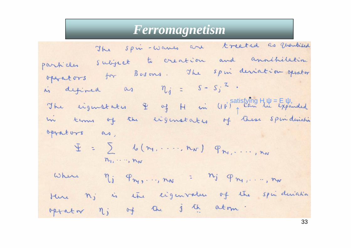
33
Ferromagnetism
, satisfying H ψ = E ψ,↑
34
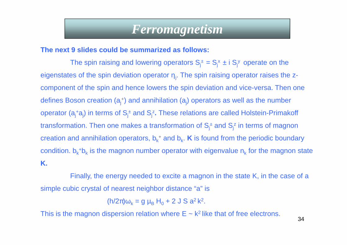
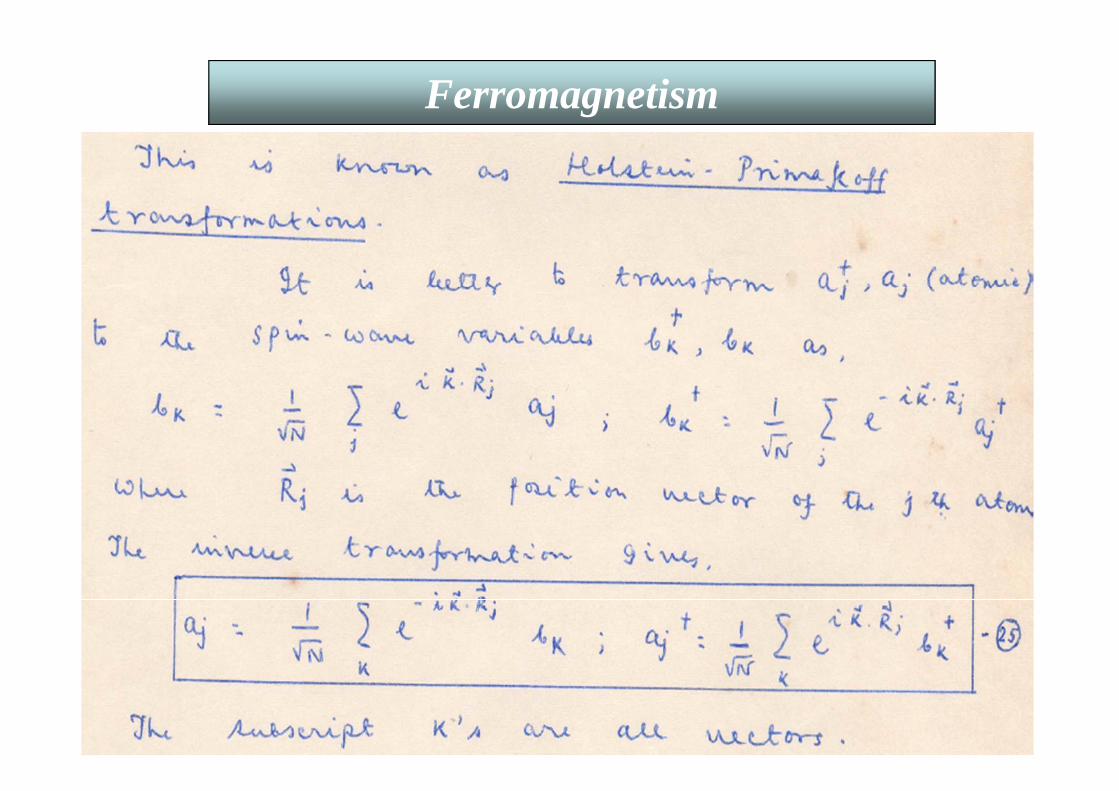
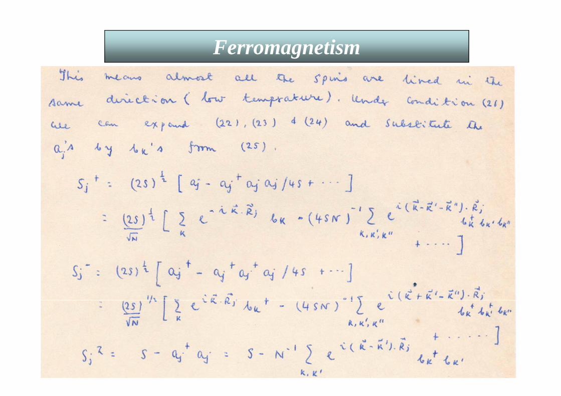
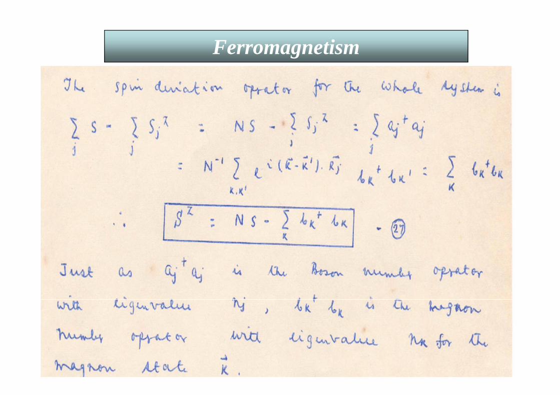
FerromagnetismThe next 9 slides could be summarized as follows:
The spin raising and lowering operators Sj± = Sj
x ± i Sjy operate on the
eigenstates of the spin deviation operator ηj. The spin raising operator raises the z-
component of the spin and hence lowers the spin deviation and vice-versa. Then one
defines Boson creation (aj+) and annihilation (aj) operators as well as the number
operator (aj+aj) in terms of Sj
± and Sjz. These relations are called Holstein-Primakoff
transformation. Then one makes a transformation of Sj± and Sj
z in terms of magnon
creation and annihilation operators, bk+ and bk. K is found from the periodic boundary
condition. bk+bk is the magnon number operator with eigenvalue nk for the magnon state
K.
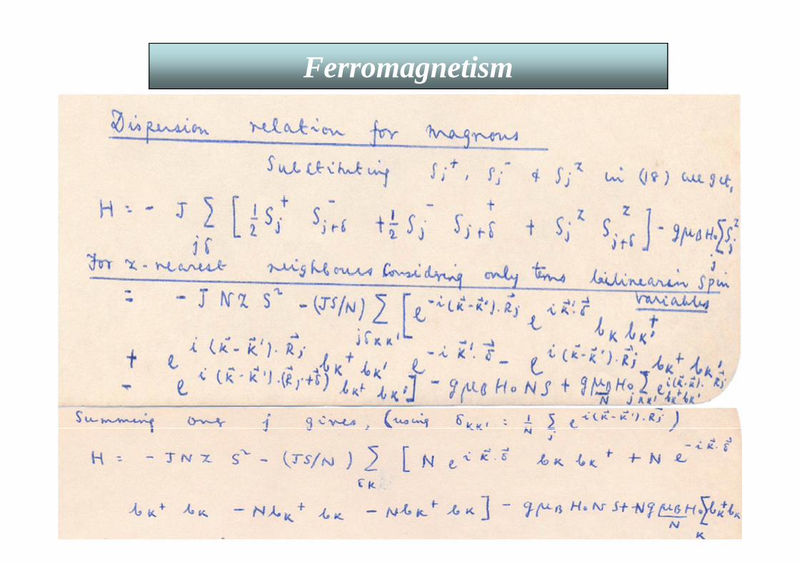
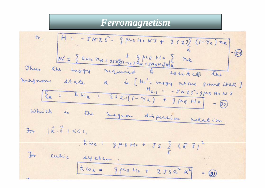
Finally, the energy needed to excite a magnon in the state K, in the case of a
simple cubic crystal of nearest neighbor distance “a” is
(h/2π)ωk = g µB H0 + 2 J S a2 k2.
This is the magnon dispersion relation where E ~ k2 like that of free electrons.

35
Ferromagnetism

36
Ferromagnetism
37
Ferromagnetism

38
Ferromagnetism
39
Ferromagnetism
40
Ferromagnetism
41
Ferromagnetism

42
Ferromagnetism
43
Ferromagnetism
44
Ferromagnetism

45
Ferromagnetism
D(ω) d ω = g(k) d3k

46
Ferromagnetism
47
Ferromagnetism
48
Ferromagnetism
49
Ferromagnetism
50
Ferromagnetism
51
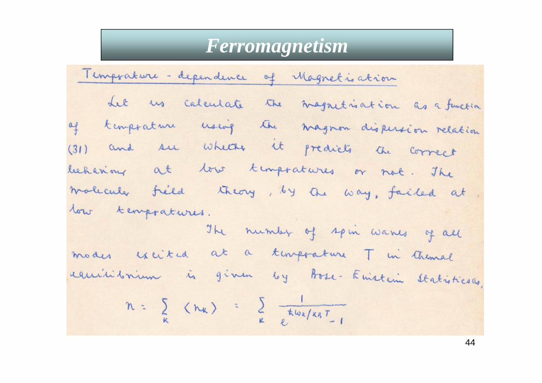
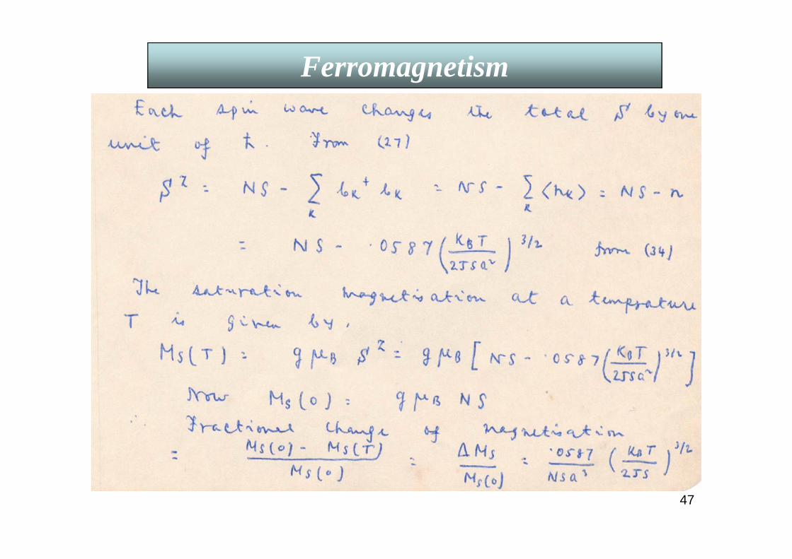
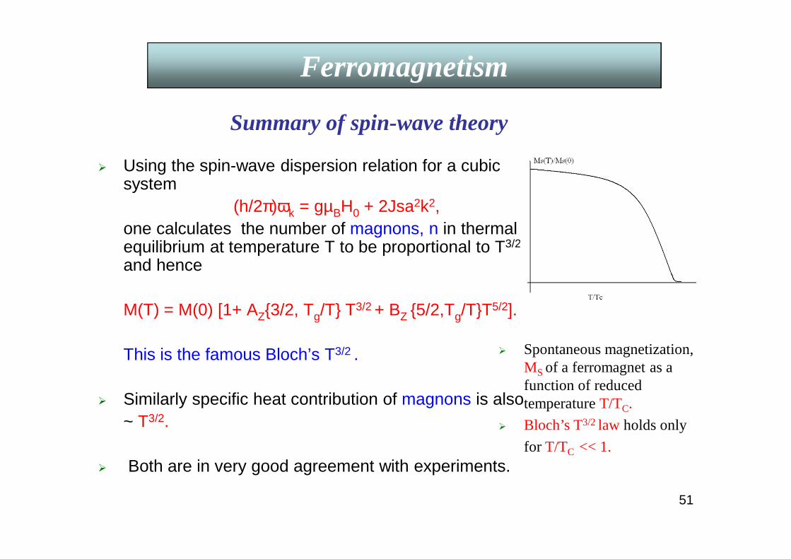
Using the spin-wave dispersion relation for a cubic system
(h/2π)ωk = gµBH0 + 2Jsa2k2,one calculates the number of magnons, n in thermal equilibrium at temperature T to be proportional to T3/2
and hence
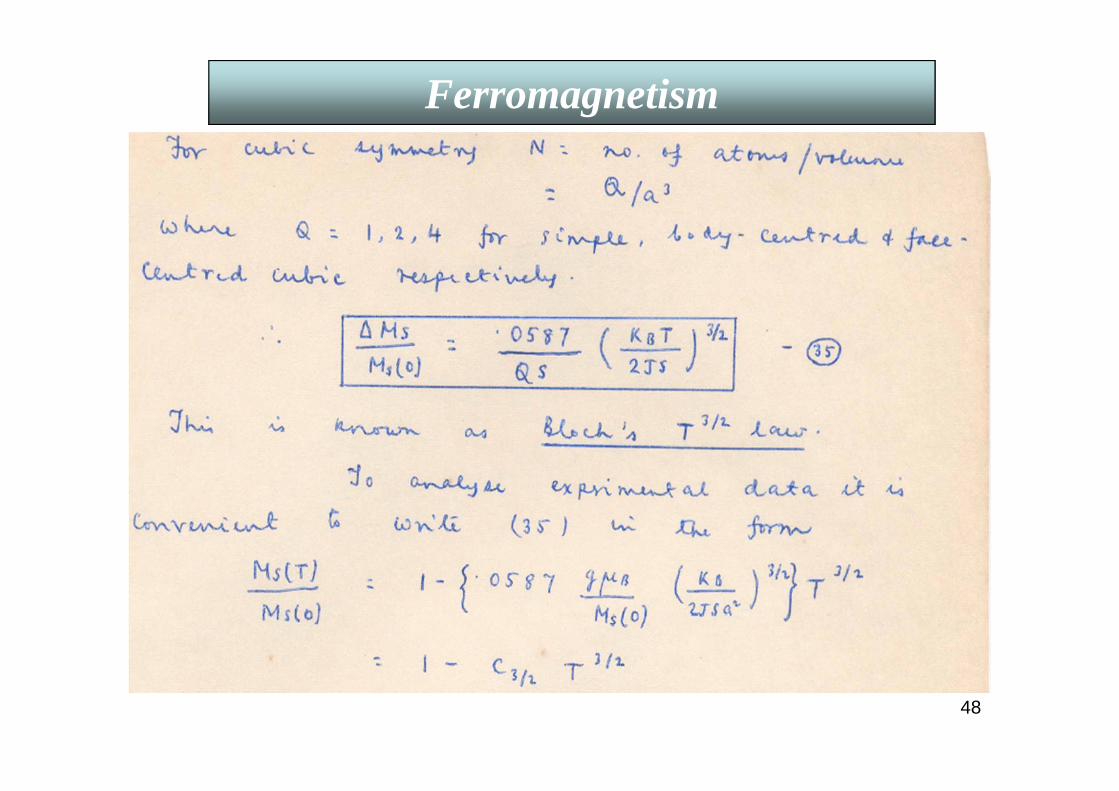
M(T) = M(0) [1+ AZ3/2, Tg/T T3/2 + BZ 5/2,Tg/TT5/2].
This is the famous Bloch’s T3/2 .
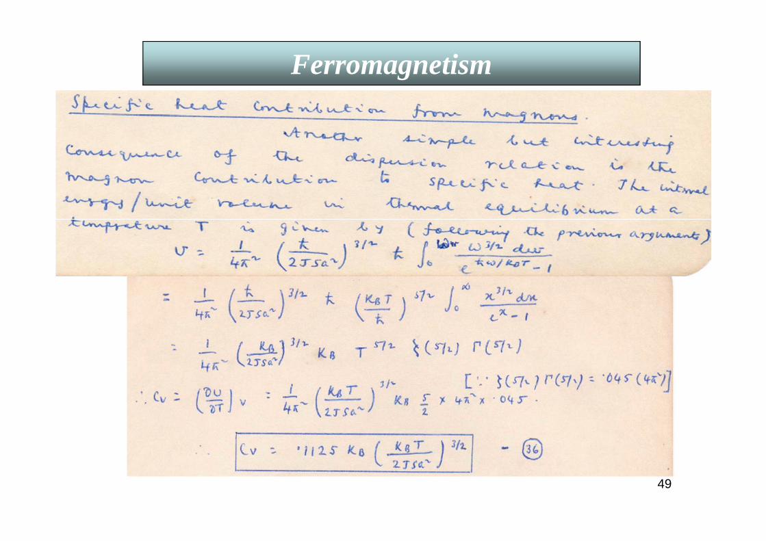
Similarly specific heat contribution of magnons is also ~ T3/2.
Both are in very good agreement with experiments.
Ferromagnetism
Spontaneous magnetization, MS of a ferromagnet as a function of reduced temperature T/TC.
Bloch’s T3/2 law holds only
for T/TC << 1.
FerromagnetismFerromagnetism
Summary of spin-wave theory
52
Ferromagnetism
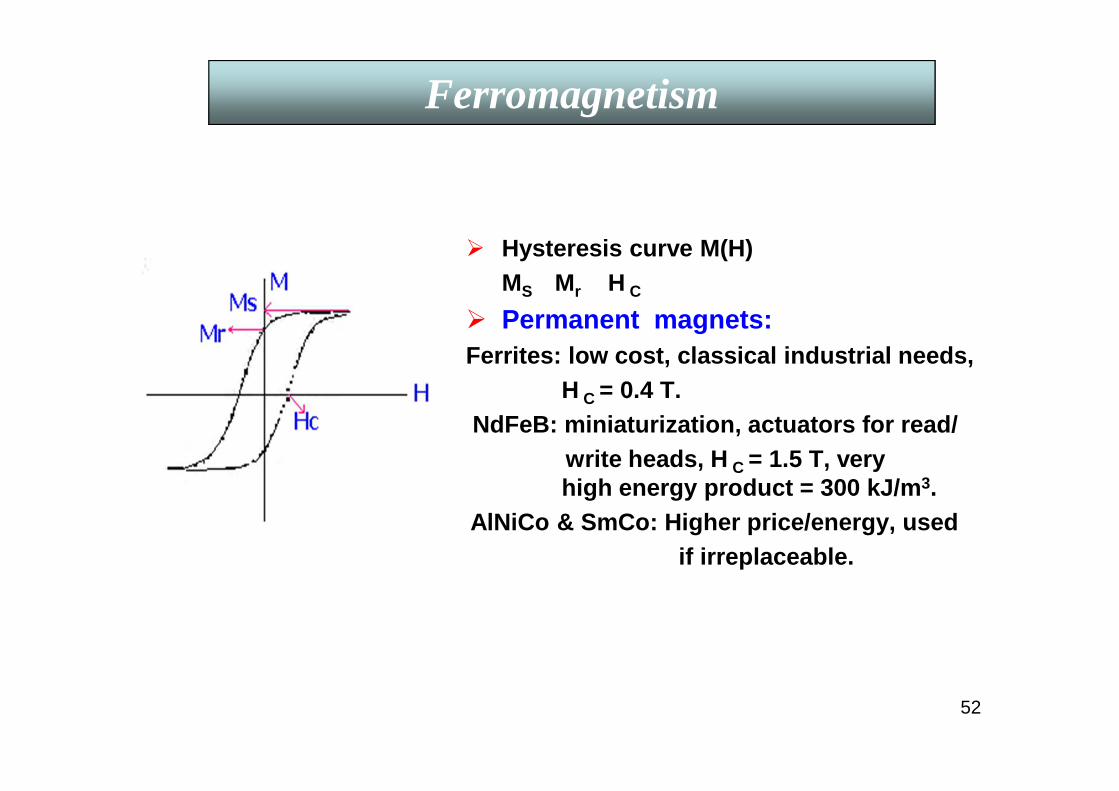
Hysteresis curve M(H)MS Mr H C
Permanent magnets:Ferrites: low cost, classical industrial needs,
H C = 0.4 T.NdFeB: miniaturization, actuators for read/
write heads, H C = 1.5 T, very high energy product = 300 kJ/m 3.
AlNiCo & SmCo: Higher price/energy, usedif irreplaceable.
53
Ferromagnetism
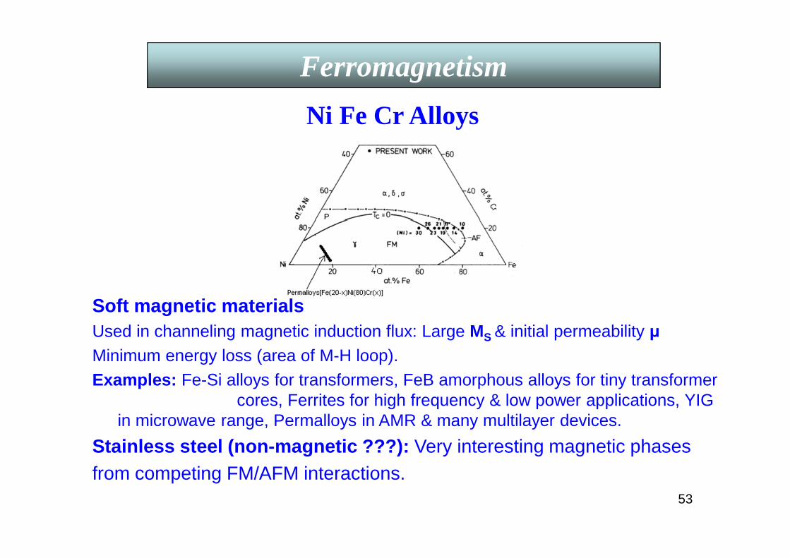
Soft magnetic materialsUsed in channeling magnetic induction flux: Large MS & initial permeability µMinimum energy loss (area of M-H loop).Examples: Fe-Si alloys for transformers, FeB amorphous alloys for tiny transformer
cores, Ferrites for high frequency & low power applications, YIG in microwave range, Permalloys in AMR & many multilayer devices.
Stainless steel (non-magnetic ???): Very interesting magnetic phasesfrom competing FM/AFM interactions.
Ni Fe Cr Alloys

54
Collective-electron or band theory of ferromagnetism
The localized-moment theory breaks down in two
aspects. The magnetic moment on each atom or ion
should be the same in both the ferromagnetic and
paramagnetic phases & its value should correspond to
an integral number of µB. None are observed
experimentally. Hence the need of a band theory or
collective-electron theory. In Fe, Ni, and Co, the Fermi
energy lies in a region of overlapping 3d and 4s bands
as shown in Fig. 1. The rigid-band model assumes that
the structures of the 3d and 4s bands do not change
markedly across the 3d series and so any differences in
electronic structure are caused entirely by changes in
the Fermi energy (EF). This is supported by detailed
band structure calculations.
Fig. 1: Schematic 3d and 4s densities of states in transition metals. The positions of the Fermi levels (EF) in Zn, Cu, Ni, Co, Fe, and Mn are shown.
55
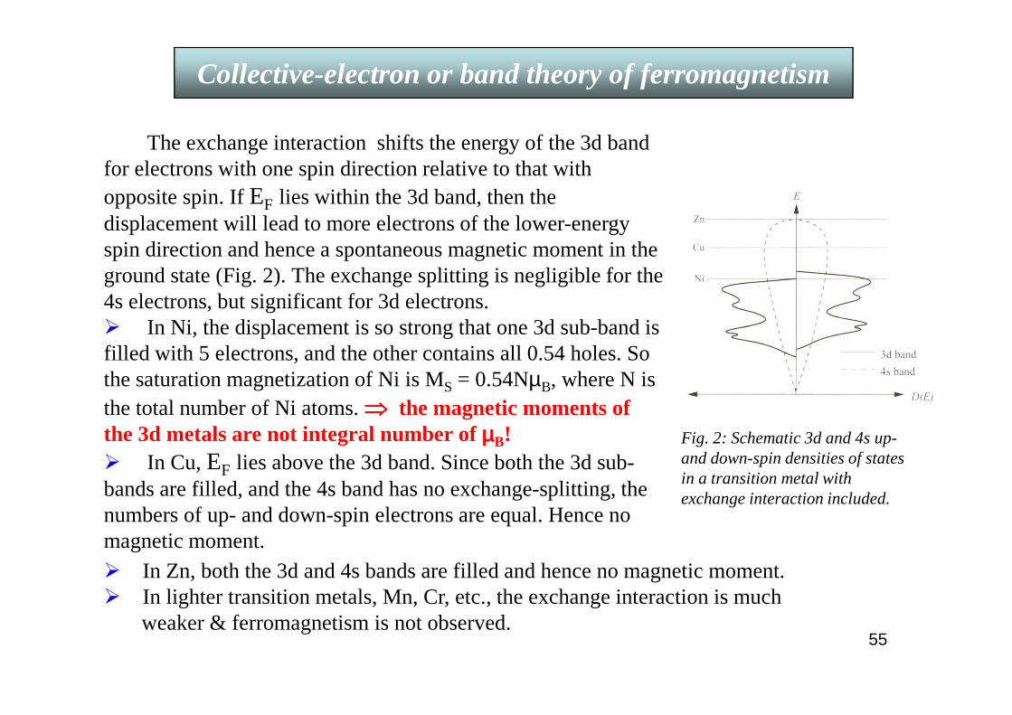
Collective-electron or band theory of ferromagnetism
The exchange interaction shifts the energy of the 3d band for electrons with one spin direction relative to that with opposite spin. If EF lies within the 3d band, then the displacement will lead to more electrons of the lower-energy spin direction and hence a spontaneous magnetic moment in the ground state (Fig. 2). The exchange splitting is negligible for the 4s electrons, but significant for 3d electrons. In Ni, the displacement is so strong that one 3d sub-band is filled with 5 electrons, and the other contains all 0.54 holes. So the saturation magnetization of Ni is MS = 0.54NµB, where N is the total number of Ni atoms. ⇒⇒⇒⇒ the magnetic moments of the 3d metals are not integral number of µµµµB! In Cu, EF lies above the 3d band. Since both the 3d sub-bands are filled, and the 4s band has no exchange-splitting, the numbers of up- and down-spin electrons are equal. Hence no magnetic moment.
Fig. 2: Schematic 3d and 4s up-and down-spin densities of states in a transition metal with exchange interaction included.
In Zn, both the 3d and 4s bands are filled and hence no magnetic moment. In lighter transition metals, Mn, Cr, etc., the exchange interaction is much
weaker & ferromagnetism is not observed.
56
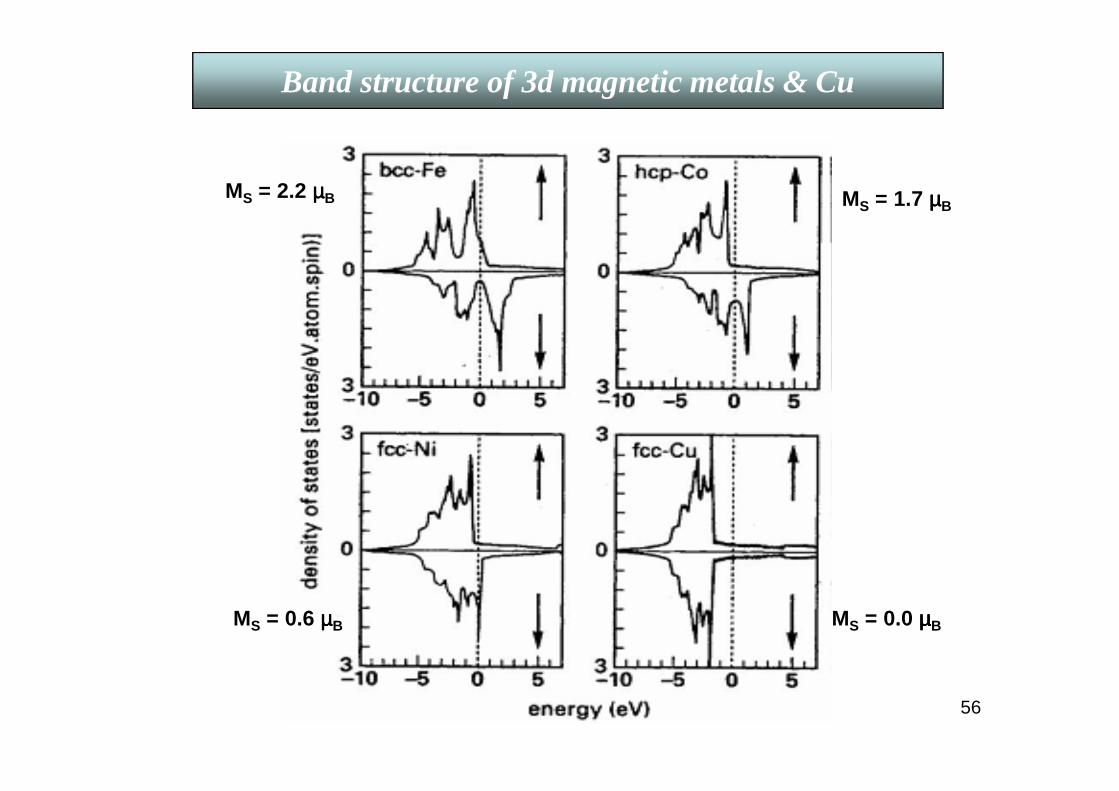
Band structure of 3d magnetic metals & Cu
MS = 2.2 µµµµB MS = 1.7 µµµµB
MS = 0.6 µµµµB MS = 0.0 µµµµB

57
The Slater-Pauling curve(1930)The collective-electron and rigid-band models are further supported by the well-known plot known as the Slater-Pauling curve. They calculated the saturation magnetization as a continuous function of the number of 3d and 4s valence electrons per atom across the 3d series. They used the rigid-band model, and obtained a linear increase in saturation magnetization from Cr to Fe, then a linear decrease, reaching zero magnetization at an electron density between Ni and Cu. Their calculated values agree well with those measured for Fe, Co, and Ni, as well as Fe-Co, Co-Ni, and Ni-Cu alloys. The alloys on the right-hand side are strong ferromagnets. The slope of the branch on the right is −1 when the charge difference of the constituent atoms is small, Z ~ < 2. The multiple branches (on left) with slope ≈ 1, as expected for rigid bands, are for alloys of late 3d elements with early 3d elements for which the 3d-states lie well above the Fermi level of the ferromagnetic host & we have to invoke Friedel’s virtual bound states.
The average atomic moment is plotted against the number of valence (3d + 4s) electrons.
58
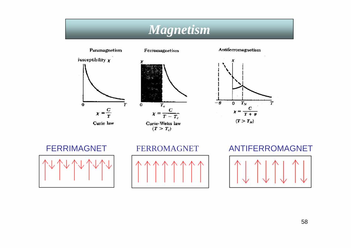
Magnetism
FERRIMAGNET ANTIFERROMAGNETFERROMAGNET
59
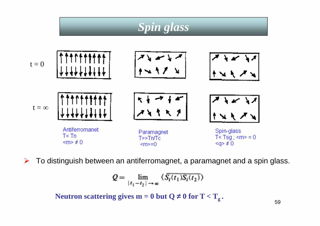
Spin glass
To distinguish between an antiferromagnet, a paramagnet and a spin glass.
t = 0
t = ∞
Neutron scattering gives m = 0 but Q ≠≠≠≠ 0 for T < Tg .

60
• The research on magnetism till late 20th century focused on its basic understanding and also on applications as soft and hard magnetic materials.
• In 1980’s it was observed that surface and interface properties deviate considerably from those of the bulk. With the advent of novel techniques
e-beam evaporation Ion-beam sputtering Magnetron sputtering Molecular beam epitaxy (MBE)
excellent magnetic thin filmscould be prepared with tailor-made properties which can not be obtained from bulk materials alone. Magnetic recording industry was also going for miniaturization and thin film technology fitted their requirement.
R & D in Magnetic Materials after 1973
• Then came, for the first time, the industrial application of electronic properties which depend on the spin of the electrons giving rise to the so-called Giant Magnetoresistance(GMR),discovered in 1986.
• Since early 80’s the Anisotropic Magnetoresistance effect (AMR)has been used in a variety of applications, especially in read heads in magnetic tapes and later on in hard-disk systems, gradually replacing the older inductive thin film heads. Now, GMR recording heads offer a stiff competition to those using AMR effects.
So, what is Magnetoresistance ???

61
I. Ordinary or normal magnetoresistance (OMR) Due to the Lorentz force acting on the electron trajectories in a
magnetic field. MR ~ B2 at low fields. MR is significant only at low temperatures for pure materials at high filds.
II. Anisotropic magnetoresistance (AMR) in a ferromagnetIn low field LMR is positive and TMR is negative.
Negative MR after saturation due to quenchingof spin-waves by magnetic field.
FAR is an inherent property of FM materials originating from spin-orbit interaction of conduction electrons withlocalized spins.
FAR(ferromagnetic anisotropy of resistivity)= (∆ρ//s- ∆ ρ⊥s )/ ρ//s
Magnetoresistance

62
• RKKY interaction ~ cos(2kf r)/(2kf r)3 .
• Established by experiments on light scattering by spin waves.
[ P. Grünberg et al., Phys. Rev. Lett. 57, 2442(1986).]
At high fields the spins align with the field (saturating at Hsat)and the resistance is reduced.
Magnetoresistance is negative!
At low fields the interlayer antiferromgnetic coupling causes the spins in adjacent layers to be antiparallel and the resistance is high
III. Giant Magnetoresistance (GMR)Fe-Cr is a lattice matched pair : Exchange coupling of ferromagnetic Fe
layers through Cr spacers gives rise to a negative giant magnetoresistance (GMR) with the application of a magnetic field.
IntroductionMagnetoresistance
63
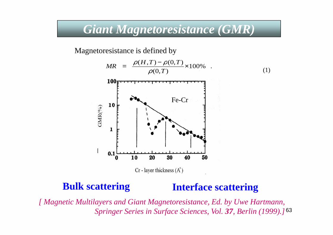
Fe-Cr
Magnetoresistance is defined by
.%100),0(
),0(),( ×−=T
TTHMR
ρρρ
(1)
Giant Magnetoresistance (GMR)Giant Magnetoresistance (GMR)
Bulk scattering Interface scattering[ Magnetic Multilayers and Giant Magnetoresistance, Ed. by Uwe Hartmann,
Springer Series in Surface Sciences, Vol. 37, Berlin (1999).]
64
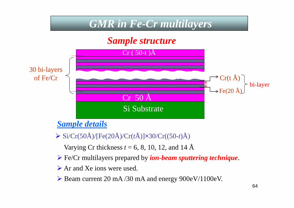
Sample structure
Cr(t Å)30 bi-layers
of Fe/Cr
Sample details Si/Cr(50Å)/[Fe(20Å)/Cr(tÅ)]×30/Cr((50-t)Å)
Varying Cr thickness t = 6, 8, 10, 12, and 14 Å
Cr ( 50-t )Å
Cr 50 ÅSi Substrate
Fe/Cr multilayers prepared by ion-beam sputtering technique.
Ar and Xe ions were used.
Beam current 20 mA /30 mA and energy 900eV/1100eV.
Fe(20 Å)bi-layer
GMR in Fe-Cr multilayers

65
GMR vs. H for 2 samples. Negative GMR of 21 % at 10 K and 8 % at 300 K with Hsat≈ 13 kOe. Hardly any hysteresis⇒ strong AF coupling.
GMR in Fe-Cr multilayers
66
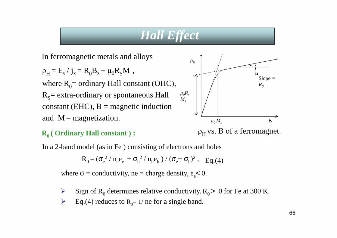
ρH = Ey / jx = R0Bz + µ0RSM ,
where R0= ordinary Hall constant (OHC),
RS= extra-ordinary or spontaneous Hall
constant (EHC), B = magnetic induction
and M = magnetization.
In ferromagnetic metals and alloys
µ0 Ms
µ0Rs
Ms
Slope= R0
B
ρH
ρH vs. B of a ferromagnet.
Hall Effect
R0 ( Ordinary Hall constant ) :
In a 2-band model (as in Fe ) consisting of electrons and holes
R0 = (σe2 / neee + σh
2 / nheh ) / (σe+ σh)2 ,
where σ = conductivity, ne = charge density, ee< 0.
Sign of R0 determines relative conductivity. R0 > 0 for Fe at 300 K.
Eq.(4) reduces to R0= 1/ ne for a single band.
Eq.(4)

67
RS ( Extra-ordinary or spontaneous Hall constant ) : a) Classical Smit asymmetric scattering(AS).b) Non-classical transport (side-jump).
Boltzmann Eq. is correct to the lowest order in («1) (τ = relaxation time),
true for pure metals and dilute alloys at low temperatures.
RS caused by AS of electrons by impurities in the presence of spin-orbit
interaction in a ferromagnet .
Boltzmann Eq.
a) Classical Smit asymmetric scattering (AS)
,
where [s] = relaxation frequency tensor ~ impurity concentration. Off-diagonal elements describe AS proportional toM.
Diagonal elements give Ohmic ρ.
Boundary condition: jy= 0⇒⇒⇒⇒ ρH and ρ.
RS= aρ.
[L. Berger, Phys. Rev. 177, 790(1969).]
FEτh
[ ] jse
mBjEen
dt
pd rrrrr
−×+=
Introduction (theory)Hall Effect
68
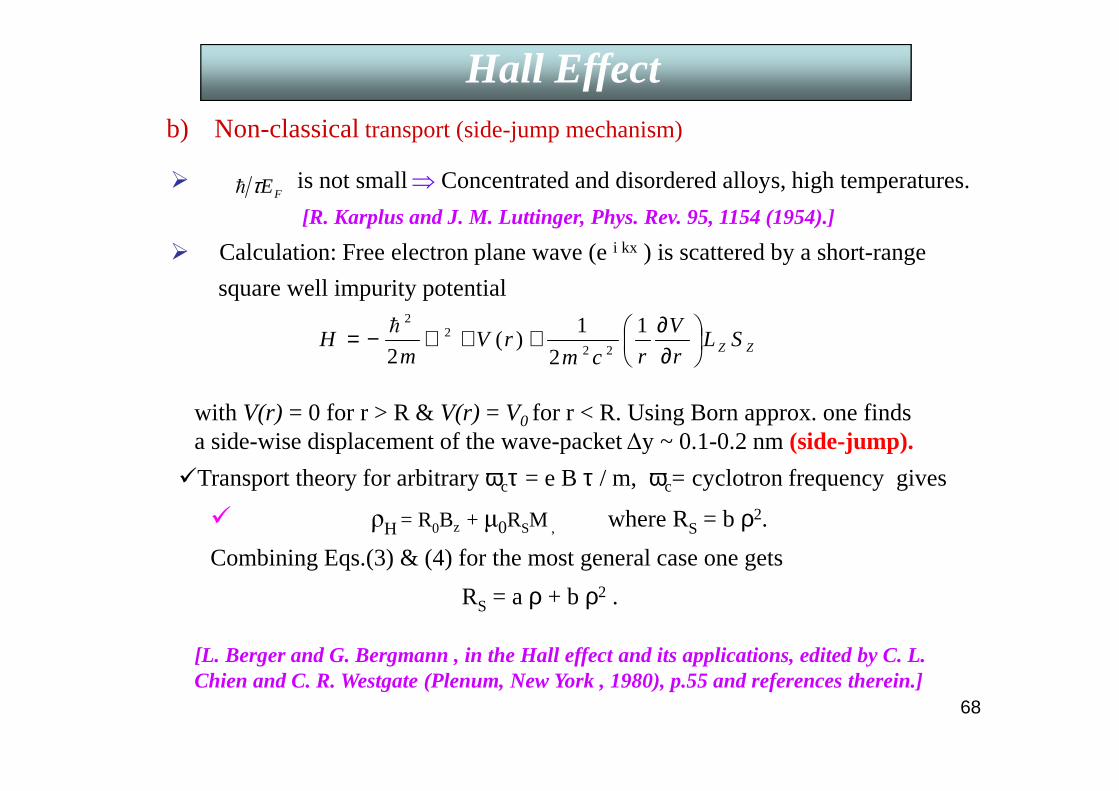
b) Non-classicaltransport (side-jump mechanism)
is not small⇒ Concentrated and disordered alloys, high temperatures.
[R. Karplus and J. M. Luttinger, Phys. Rev. 95, 1154 (1954).]
Calculation: Free electron plane wave (e i kx ) is scattered by a short-range
square well impurity potential
with V(r) = 0 for r > R & V(r) = V0 for r < R. Using Born approx. one finds a side-wise displacement of the wave-packet ∆y ~ 0.1-0.2 nm (side-jump).
FEτh
ZZ SLr
V
rcmrV
mH
∂∂++∇−= 1
2
1)(
2 22
22
h
Transport theory for arbitrary ωcτ = e B τ / m, ωc= cyclotron frequency gives
ρH = R0Bz + µ0RSM , where RS = b ρ2.
Combining Eqs.(3) & (4) for the most general case one gets
RS = a ρ + b ρ2 .
[L. Berger and G. Bergmann , in the Hall effect and its applications, edited by C. L. Chien and C. R. Westgate (Plenum, New York , 1980), p.55 and references therein.]
Introduction (theory)Hall Effect
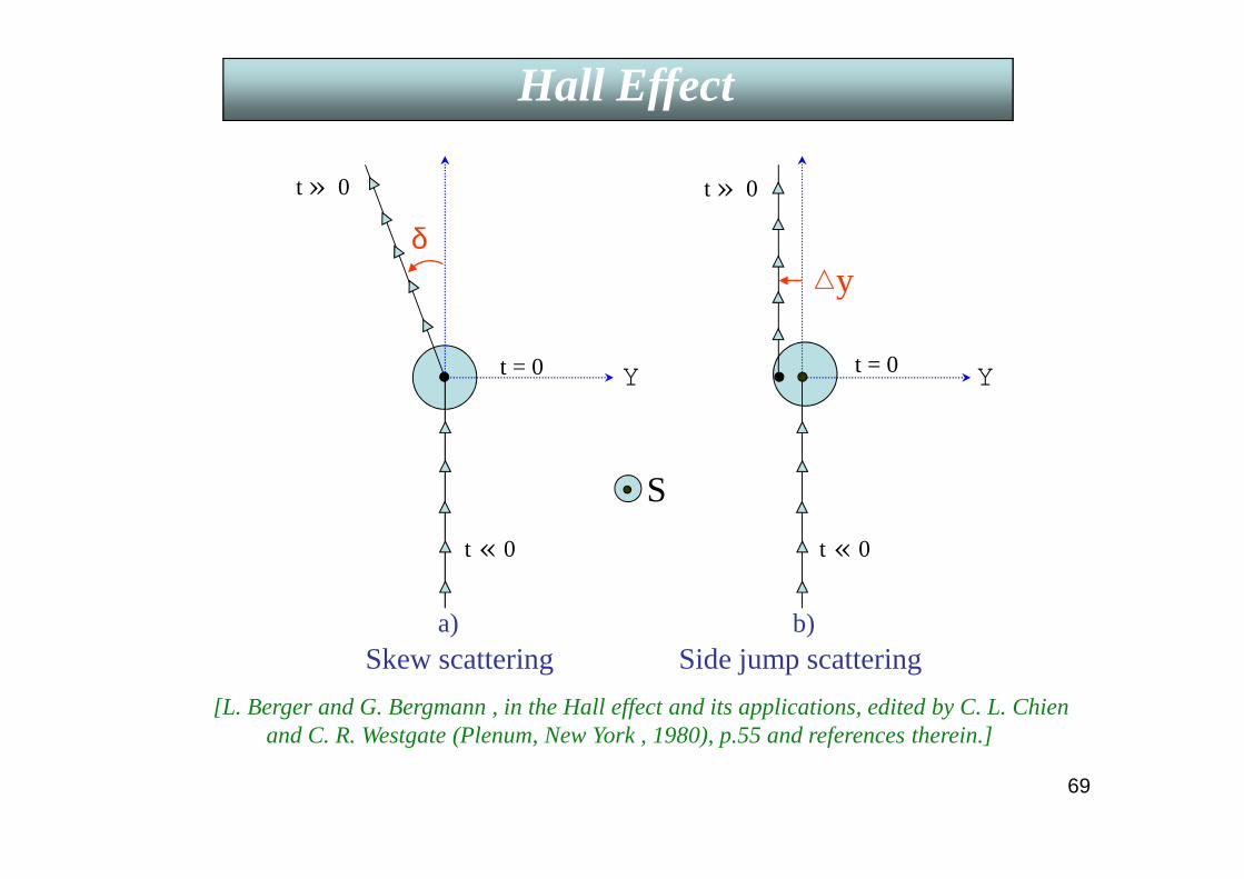
t = 0 t = 0
t « 0
t » 0
t « 0
YY
t » 0
δy
S
a) b)Skew scattering Side jump scattering
[L. Berger and G. Bergmann , in the Hall effect and its applications, edited by C. L. Chienand C. R. Westgate (Plenum, New York , 1980), p.55 and references therein.]
Hall Effect
69
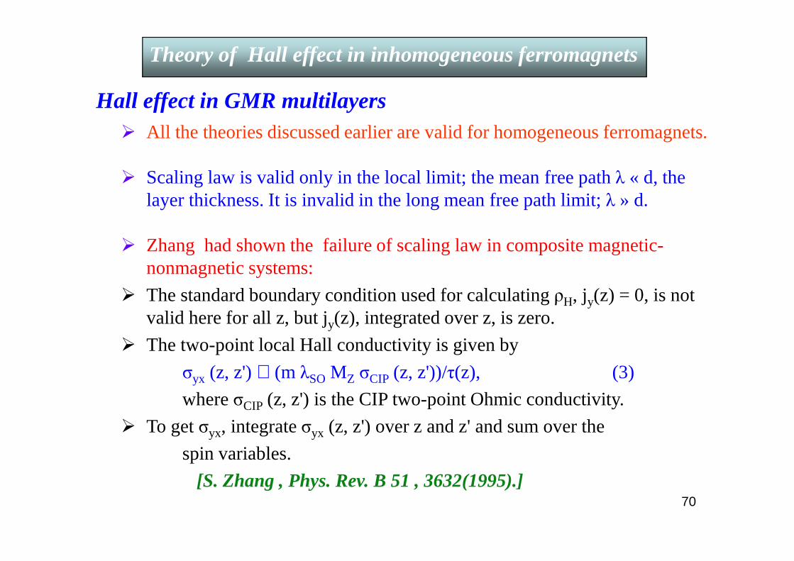
Hall effect in GMR multilayers All the theories discussed earlier are valid for homogeneous ferromagnets.
Scaling law is valid only in the local limit; the mean free path λ « d, the layer thickness. It is invalid in the long mean free path limit; λ » d.
Zhang had shown the failure of scaling law in composite magnetic-nonmagnetic systems:
The standard boundary condition used for calculating ρH, jy(z) = 0, is not valid here for all z, but jy(z), integrated over z, is zero.
The two-point local Hall conductivity is given by
σyx (z, z') ∝ (m λSO MZ σCIP (z, z'))/τ(z), (3)
where σCIP (z, z') is the CIP two-point Ohmic conductivity.
To get σyx, integrate σyx (z, z') over z and z' and sum over the
spin variables.
[S. Zhang , Phys. Rev. B 51 , 3632(1995).]
Theory of Hall effect in inhomogeneous ferromagnetsTheory of Hall effect in inhomogeneous ferromagnets
70
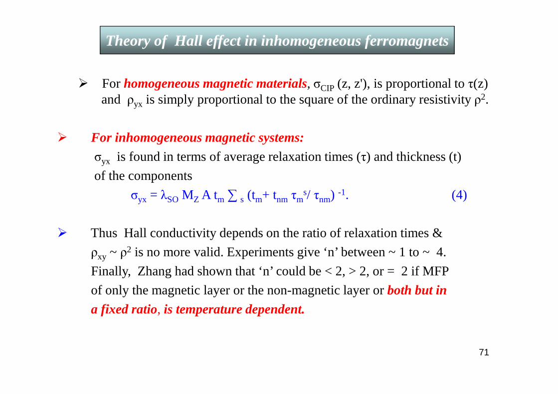
For homogeneous magnetic materials, σCIP (z, z'), is proportional to τ(z) and ρyx is simply proportional to the square of the ordinary resistivity ρ2.
For inhomogeneous magnetic systems:
σyx is found in terms of average relaxation times (τ) and thickness (t)
of the components
σyx = λSO MZ A tm∑ s (tm+ tnm τms/ τnm) -1. (4)
Thus Hall conductivity depends on the ratio of relaxation times &
ρxy ~ ρ2 is no more valid. Experiments give ‘n’ between ~ 1 to ~ 4.
Finally, Zhang had shown that ‘n’ could be < 2, > 2, or = 2 if MFP
of only the magnetic layer or the non-magnetic layer or both but in
a fixed ratio, is temperature dependent.
Theory of Hall effect in inhomogeneous ferromagnets
71
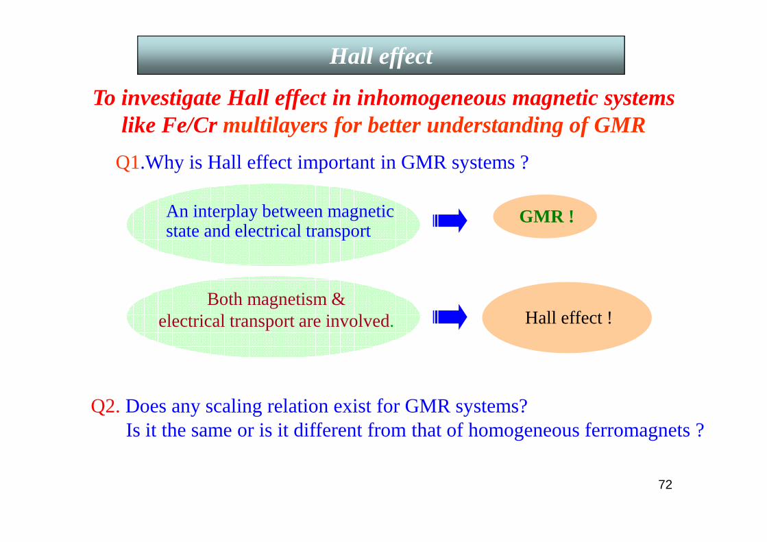
Motivation
An interplay between magnetic state and electrical transport
GMR !
To investigate Hall effect in inhomogeneous magnetic systems like Fe/Cr multilayers for better understanding of GMR
Both magnetism & electrical transport are involved. Hall effect !
Q1.Why is Hall effect important in GMR systems ?
Q2. Does any scaling relation exist for GMR systems? Is it the same or is it different from that of homogeneous ferromagnets ?
Hall effect
72
Hall effect and Transverse/Longitudinal Magnetoresistance measured by 5-probe and 4-probe dc methods, respectively using
a home-made variable temperature cryostat and a 7 T superconducting magnet
Accuracy of VH ≈ 1 in 3000,, ,, VR≈ 1 in 105 .
Magnetization measured with a Quantum Design SQUID Magnetometer.
Experimental Techniques
73
0 1 2 3 4 5 6 70.0
1.5
3.0
4.5
6.0
7.5
9.0
Peak position
T = 300K
T = 4.2K
F8 (30L)
Hal
l Res
istiv
ity (
10 -9 Ω
m)
Field (tesla)
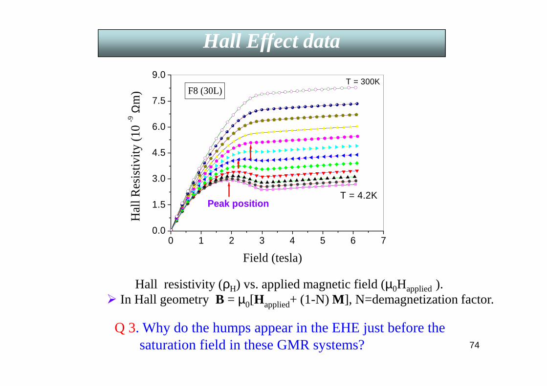
Hall resistivity (ρH) vs. applied magnetic field (µ0Happlied).
Q 3. Why do the humps appear in the EHE just before the saturation field in these GMR systems?
Hall Effect dataHall Effect data
In Hall geometry B = µ0[Happlied+ (1-N) M], N=demagnetization factor.
74

0 1 2 3 4 5 6 7
-0.32
-0.24
-0.16
-0.08
0.00
T = 300K
T = 4.2K
F8 (30L)M
agne
tore
sist
ance
Rat
io
Field (tesla)
MR ratio vs. applied magnetic field (µ0Happlied).
MagnetoresistanceMagnetoresistancedata
75

Explanation of anomalous humps in EHE lies in its correlation with GMR
Plots of RsM, M and ρ against applied magnetic field (µ0Happlied ).All show saturation around 3 tesla.
Hall Effect Hall Effect
76
5.6 5.8 6.0 6.20.0
0.3
0.6
0.9
1.2
1.5
F10(30L)
n = 3.45 ± 0.11
F10(10L)
n = 3.07 ± 0.04
Rs~ ρn
ln R
s
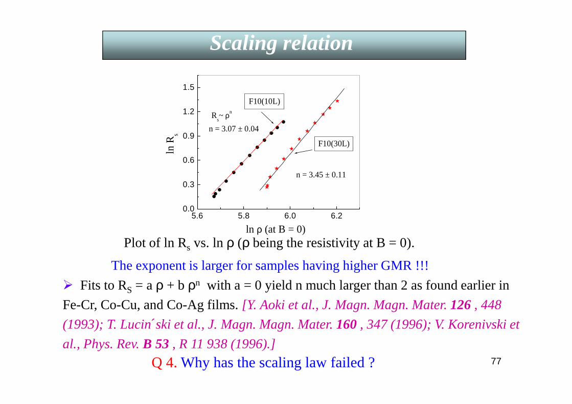
ln ρ (at B = 0)Plot of ln Rs vs. ln ρ (ρ being the resistivity at B = 0).
Q 4. Why has the scaling law failed ?
Scaling relation Scaling relation
Fits to RS = a ρ + b ρn with a = 0 yield n much larger than 2 as found earlier in
Fe-Cr, Co-Cu, and Co-Ag films. [Y. Aoki et al., J. Magn. Magn. Mater. 126 , 448
(1993); T. Lucinski et al., J. Magn. Magn. Mater. 160 , 347 (1996); V. Korenivski et
al., Phys. Rev. B 53 , R 11 938 (1996).]
The exponent is larger for samples having higher GMR !!!
77
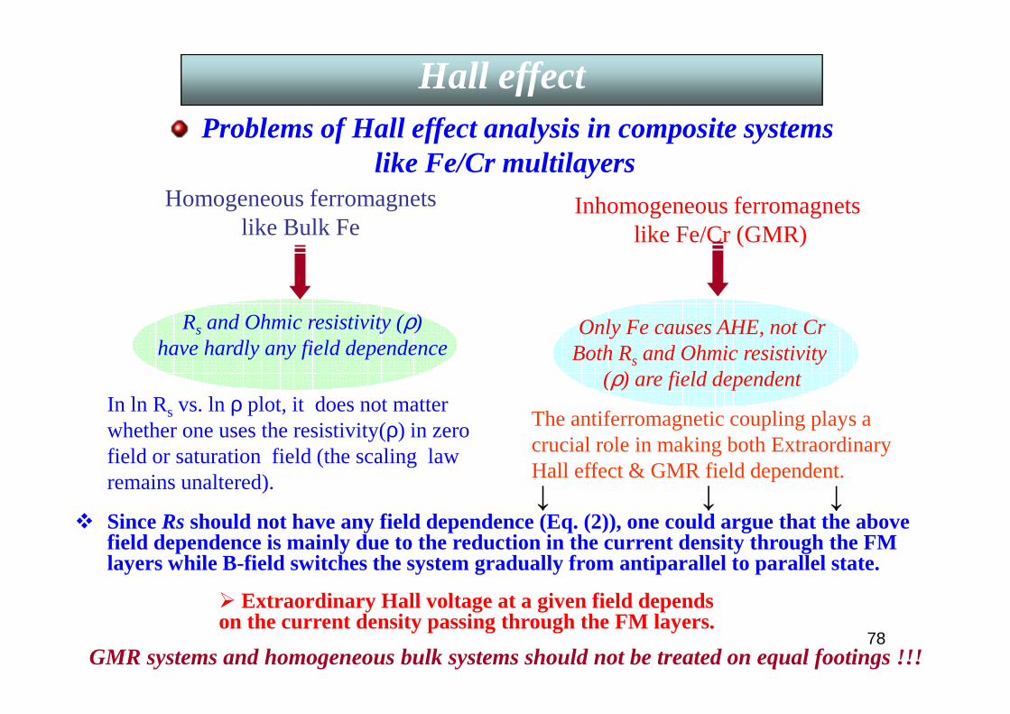
Problems of Hall effect analysis in composite systemslike Fe/Cr multilayers
Homogeneous ferromagnetslike Bulk Fe
Inhomogeneous ferromagnetslike Fe/Cr (GMR)
Rs and Ohmic resistivity (ρ) have hardly any field dependence
Only Fe causes AHE, not CrBoth Rs and Ohmic resistivity
(ρ) are field dependent
GMR systems and homogeneous bulk systems should not be treated on equal footings !!!
In ln Rs vs. ln ρ plot, it does not matter whether one uses the resistivity(ρ) in zero field or saturation field (the scaling law remains unaltered).
The antiferromagnetic coupling plays a crucial role in making both Extraordinary Hall effect & GMR field dependent.
Since Rs should not have any field dependence (Eq. (2)), one could argue that the above field dependence is mainly due to the reduction in the current density through the FM layers while B-field switches the system gradually from antiparallel to parallel state.
↓ ↓↓
Hall effectHall effect
Extraordinary Hall voltage at a given field depends on the current density passing through the FM layers.
78

5.4 5.6 5.8 6.00.0
0.4
0.8
1.2
1.6
Rs~ ρn
n = 1.95 ± 0.03
Master plot for (Fe/Cr)10
ln R
s
ln ρ
F8 F10 F12 F14
5.4 5.7 6.0 6.3
0.0
0.5
1.0
1.5
2.0
Rs~ ρn
Master plot for (Fe/Cr)30
n = 2.05 ± 0.03
F8 F10 F12 F14
ln R
s
ln ρ
Plot of ln Rs (B) vs. ln ρ (B).
Scaling exponent n = 1.95 for 10 bi-layer &
2.05 for 30 bi-layer series. Each plot has 4 samples x 4 fields x
12 temperatures = 192 points.
Scaling relation Scaling relation
A realization of the charge confinement in a Quantum Well
Spin-polarized quantum well states are formed in the non-magnetic Cr spacer layer due to multiple reflections of electrons from the interfaces of adjacent magnetic Fe layers. They mediate the exchange coupling between the FM layers.
Majority electrons get gradually confined to the Cr spacer layer as H increases. This reduces the current in the Fe layers which, in turn, causes the decrease of both Rs & ρ.
79

80
Robotics and automotive sensors (e.g. in car). Measuring electrical current in cables. Pressure sensors (GMR in conjunction with
magnetostrictive materials), Microphone. Solid-state Compass systems. Sensitive detection of magnetic field. Magnetic recording and detection of landmines.
1973: Rare earth – transition metal film in magneto-optic recording.1979: Thin film technology for heads in hard disks (both read and write processes) (IBM).1991: AMR effect using permalloy films for sensors in HDD by IBM.1997: GMR sensors in HDD by IBM.
Currently both GMR and TMRare used for application in sensors and MRAMs.
Comparison between AMR / GMR effect: In contrast to AMR, GMR is isotropic & GMR effect is more robust than AMR.
Giant Magnetoresistance (GMR)
Applications of thin-film technology
81
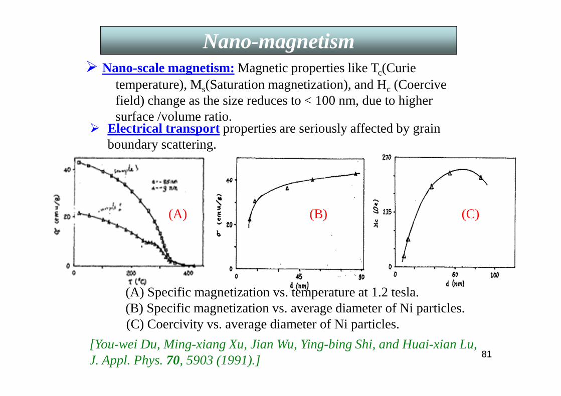
Nano-scale magnetism: Magnetic properties like Tc(Curie temperature), Ms(Saturation magnetization), and Hc (Coercivefield) change as the size reduces to < 100 nm, due to higher surface /volume ratio.
(A) (B) (C)
(A) Specific magnetization vs. temperature at 1.2 tesla.(B) Specific magnetization vs. average diameter of Ni particles.(C) Coercivity vs. average diameter of Ni particles.
[You-wei Du, Ming-xiang Xu, Jian Wu, Ying-bing Shi, and Huai-xian Lu, J. Appl. Phys. 70, 5903 (1991).]
Electrical transport properties are seriously affected by grain boundary scattering.
Nano-magnetism
82
Recording Media
A good medium must have high Mr and HC . In the year 2000 areal storage density of 65 Gbit/sq. inch was obtained in
CoCrPtTa deposited on Cr thin films/Cr80Mo20 alloy. To achieve still higher density like 400Gbit/sq. inch it is necessary to use
patterned medium instead of a continuous one. This is an assembly of nano-scale magnetically independent dots, each dot representing one bit of information.
Some techniques are self-organization of nano-particles, nano-imprints,or local ion irradiation.
Problem of reducing magnetic particle size is the so-called “Superparamagnetic limit”.
What is Superparamagnetism ???
Nano-magnetism
83
Superparamagnetism
There are several types of anisotropies, the most common is the
“magnetocrystalline”anisotropy caused by the spin-orbit interaction
in a ferromagnet. It is easier to magnetize along certain
crystallographic directions. This energy term is direction dependent
although its magnitude is much less than that of the exchange term. It
only dictates the direction of M. Thus the axis of quantization z is
always in a direction for which the anisotropy energy is minimum.
The energy of a ferromagnetic particle (many atoms) with uniaxial
anisotropy constant K1(energy/vol.) and magnetic moment µµµµ making
an angle θ with H || z-axis is (1)
84
Superparamagnetism
where V is the volume of the particle. Eq. (1) has two minima at θ = 0 and
π whose energies are
and an energy barrier in between.
Assuming thatM of the particles spend almost all their time
along one of the minima, then the no. of particles jumping from min. 1 to
min. 2 is a function of the barrier height εm – ε1, where εm = energy of the
maximum. To get εm
Put ∂ε/ ∂θ = 0 = sinθ (2K1 V cosθ + µH)

85
Superparamagnetism
sinθ = 0 gives two minima atθ = 0 and π.
The other solution gives the maximum.
Substituting cosθ in Eq. (1) one gets
where µµµµ = V M and |M| =M S.

86
The frequency of jump from min. 1 to min.2 is
Converting to relaxation time for H = 0 gives
Superparamagnetism
Neel’s estimate of f0 was 109 s-1. Current values are ~ 1010 s-1.
& K 1V = Energy barrier.
Similarly,
where

87
This table shows prominentlythe exponential behaviour of τ(R). For, say, Ni τ increases by 5 orders of magnitude as R changes from 75 to 85 Å.
If τ >> τexp, experimental time scale, no change of M could be observed during τexp “ Stable ferromagnetism”.
If τexp ~ 100 s (SQUID), 75 Å Ni particle will not show stable FM but if the probe is Mossbauer (10-8
s) it is indeed a FM.
Superparamagnetism
If τ << τexp, M will flip many many times during τexp & average M will be 0.Thus there is a loss of “ Stable ferromagnetism” since the relaxation time, τ, is too small.
88
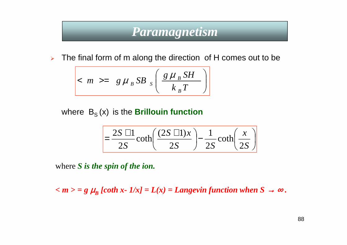
The final form of m along the direction of H comes out to be
where BS (x) is the Brillouin function
Paramagnetism
>=<
Tk
SHgSBgm
B
BSB
µµ
−
++=S
x
SS
xS
S
S
2coth
2
1
2
)12(coth
2
12
whereS is the spin of the ion.
< m > = g µµµµB [coth x- 1/x] = L(x) = Langevin function when S →→→→ ∞∞∞∞ .
89
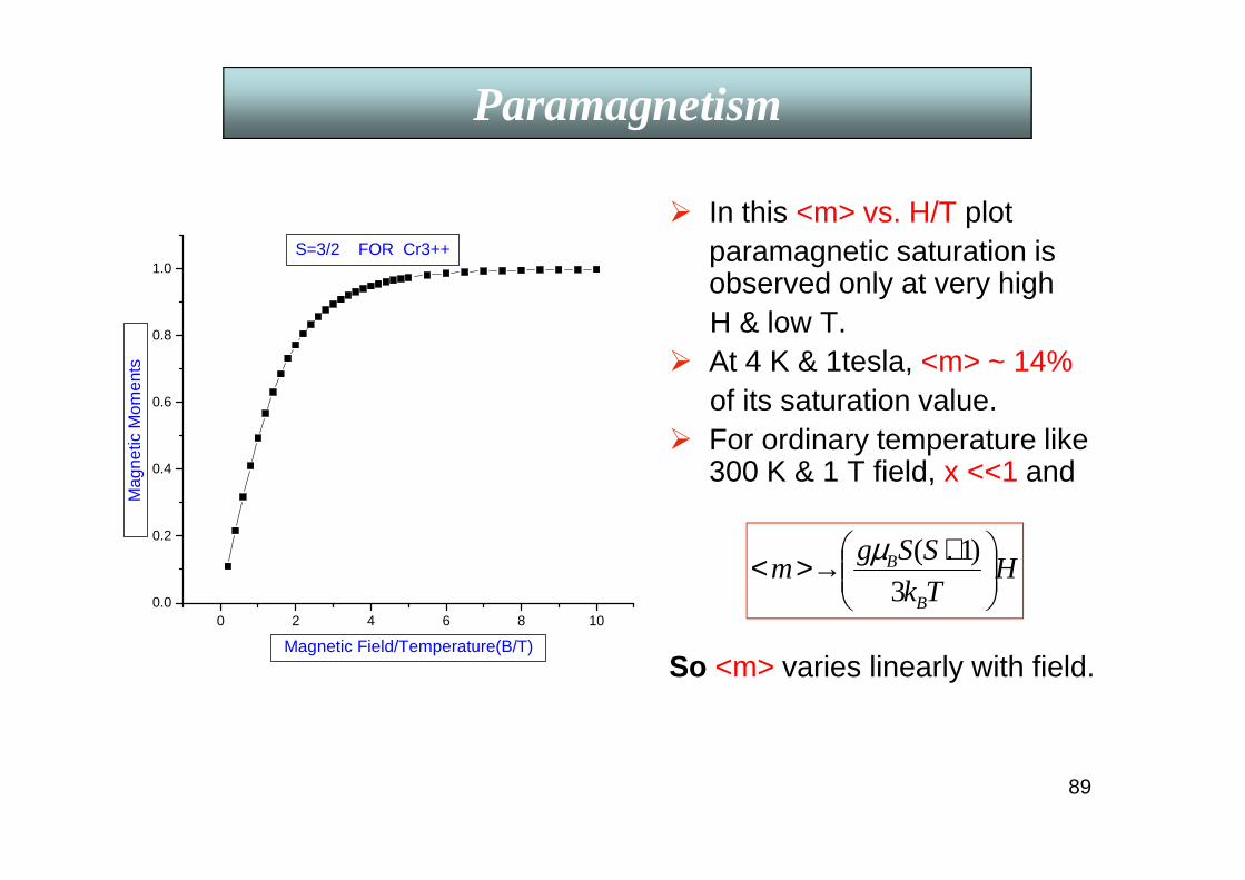
In this <m> vs. H/T plotparamagnetic saturation is observed only at very high H & low T.
At 4 K & 1tesla, <m> ~ 14%of its saturation value.
For ordinary temperature like 300 K & 1 T field, x <<1 and
.
So <m> varies linearly with field.
Paramagnetism
0 2 4 6 8 100.0
0.2
0.4
0.6
0.8
1.0S=3/2 FOR Cr3++
Mag
netic
Mom
ents
Magnetic Field/Temperature(B/T)
HTk
SSgm
B
B
+>→<3
)1(µ

90
But in a field H, M will behave as a paramagnet as shown in <m> vs. H/T plot of last page with easy saturation when all the particles align at a much lower field & higher temperature since S in Brillouin function (~ SH/T) is now 103 - 104. This is “Superparamagnetism ”(SPM) ---“super” meaning “very high” as in “Superconductor”.
Transition from stable FM to SPM shifts to smaller particle size whenT is decreased since τ is a function of V/T. The temperature, TB at which τ ~ τexp, is called the “Blocking temperature”. Above TB, SPM with all <m> vs. H/T curves coalesce to one but no hysteresis. BelowTB, it is in a “blocked” (FM) state with hysteretic Mr and H C . TBmoves to lower temperatures at higher fields due to the lowering of barrier height.
A single particle of only several Å dimension cannot be handled easily. So, experiments are carried out with an ensemble of magnetic particles with a size distribution.
Superparamagnetism
91
Superparamagnetism
0 50 100 150 200 250 3000.0
5.0x10⁻⁷
1.0x10⁻⁶
1.5x10⁻⁶
2.0x10⁻⁶
2.5x10⁻⁶
3.0x10⁻⁶
3.5x10⁻⁶
4.0x10⁻⁶
M (
emu)
T (K)
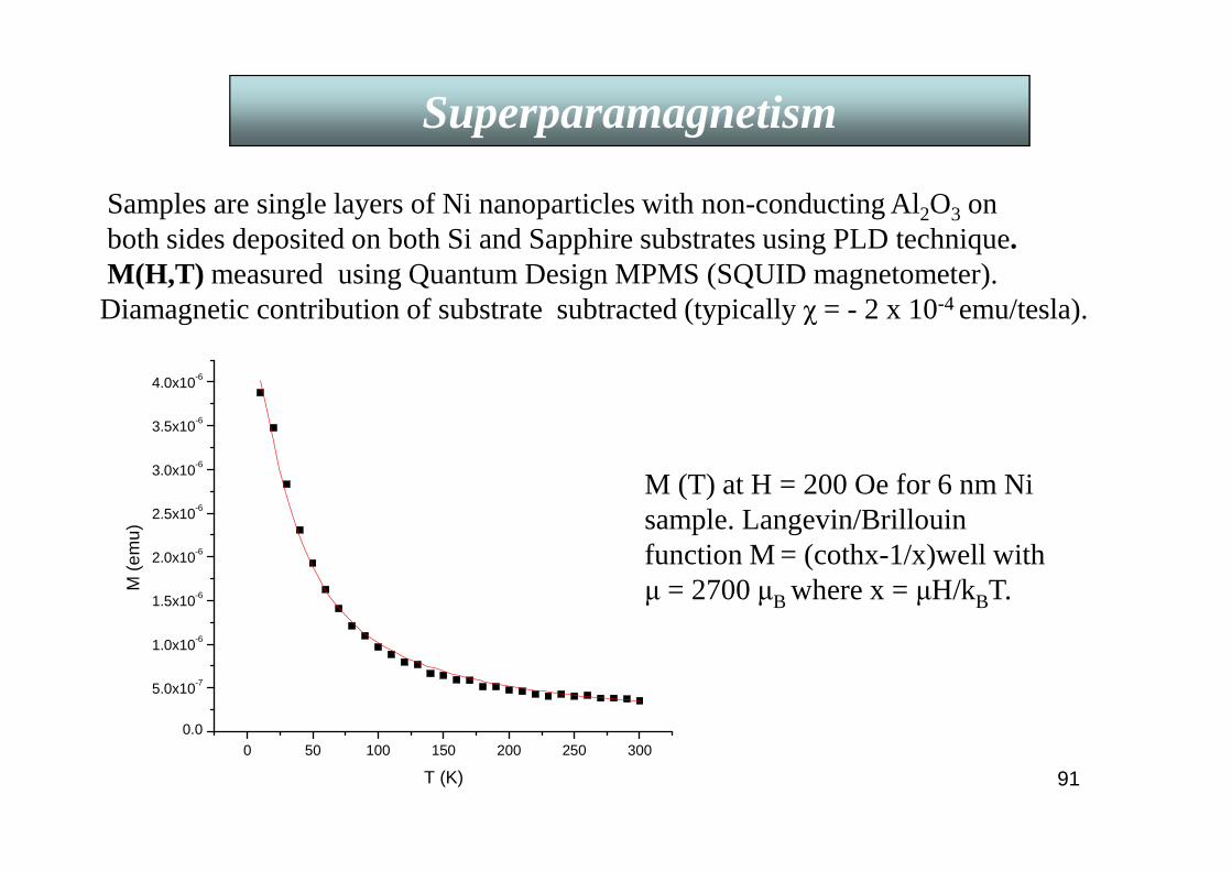
M (T) at H = 200 Oe for 6 nm Ni sample. Langevin/Brillouin function M = (cothx-1/x)well with µ = 2700 µB where x = µH/kBT.
Samples are single layers of Ni nanoparticles with non-conducting Al2O3 on both sides deposited on both Si and Sapphire substrates using PLD technique.M(H,T) measured using Quantum Design MPMS (SQUID magnetometer). Diamagnetic contribution of substrate subtracted (typically χ = - 2 x 10⁻⁴ emu/tesla).
92
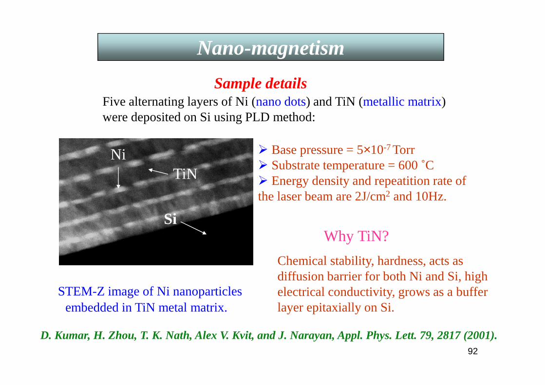
Sample details
D. Kumar, H. Zhou, T. K. Nath, Alex V. Kvit, and J. Narayan, Appl. Phys. Lett. 79, 2817 (2001).
Base pressure = 5×10⁻⁷ Torr Substrate temperature = 600 ˚C Energy density and repeatition rate of the laser beam are 2J/cm2 and 10Hz.
Five alternating layers of Ni (nano dots) and TiN (metallic matrix) were deposited on Si using PLD method:
TiNNi
STEM-Z image of Ni nanoparticlesembedded in TiN metal matrix.
SiWhy TiN?
Chemical stability, hardness, acts as diffusion barrier for both Ni and Si, high electrical conductivity, grows as a buffer layer epitaxially on Si.
Nano-magnetism

93
A cross-sectional STEM-Z image
Ni [220] || TiN[002]Ni[110] || TiN[110]
Ni [002] || TiN[002]
Ni[110] || TiN[110]
Single layer epitaxial Ni nano dots on TiN/Si(100) template
Ni separation ≈ 10 nm Triangular morphology
with 17 nm base and 9 nm height
Some have rectangularmorphology.
Thickness ofTiN = 6×32 nm.
Ni particles grow epitaxially on TiN acting as a template which also grows epitaxially on Si. Ni-nano/TiN is an ideal system for studying electrical transport in magnetic nano particles due to epitaxial growth and conducting nature of TiN .
Nano-magnetism

94
Hall Effect
0 1 2 3 4 50
1x10⁻¹⁰
2x10⁻¹⁰
3x10⁻¹⁰
4x10⁻¹⁰
5x10⁻¹⁰
6x10⁻¹⁰
T=25K
T = 300K
Hall effectNi-Nano/TiN
Hall effectPure Ni-bulk
11K 35K 60K 85K 105K 115K 135K 160K 185K 210K 235K 260K 290K
T=290K
T=11K
Hal
l Res
istiv
ity (
- ρH)(
ohm
-m)
Field (tesla)Hall resistivity (ρH) vs. applied magnetic field (µ0Happlied).
ρH is negative at all temperatures from 11 to 290 K.
In Hall geometry B = µ0[Happlied+ (1-N) M], N=demagnetization factor.So, ρH = Ro µ0 Happlied+ RSµ0 M,
Nano-magnetism
95
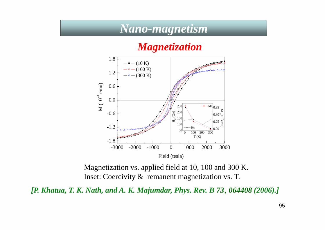
-3000 -2000 -1000 0 1000 2000 3000-1.8
-1.2
-0.6
0.0
0.6
1.2
1.8
0.20
0.25
0.30
0.35
0 100 200 30050
100
150
200
250
Hc
HC (
Oe)
T (K)
M r (10
-4emu)
Mr
M (
10-
4 em
u)
Field (tesla)
(10 K) (100 K) (300 K)
Magnetization vs. applied field at 10, 100 and 300 K.Inset: Coercivity & remanent magnetization vs. T.
Magnetization
Nano-magnetism
[P. Khatua, T. K. Nath, and A. K. Majumdar, Phys. Rev. B 73, 064408(2006).]

96
FeMn providing local magnetic field to Co layer, and NiFe is magnetically soft.
GMR > 20 %.
Read heads for HDD detect fields ~ 10 Oe.
FerromagneticSubstrate
Ta
FeMn
Co
CuNiFeTa
Antiferromagnetic
Exchange-biased Spin-valve structure

97
Tunnel Magnetoresistance (TMR)
Discovery of GMR effect in Fe/Cr superlattice in 1986 and giant tunnel magnetoresistance (TMR) effect at room temperature (RT) in 1995 opened up a new field of science and technology called spintronics. The latter provides better understanding on the physics of spin-dependent transport in heterogeneous systems. Perhaps more significantly, such studies have contributed to new generations of magnetic devices for information storage and magnetic sensors.
A magnetic tunnel junction (MTJ), which consists of a thininsulating layer (a tunnel barrier) sandwiched between twoferromagnetic electrode layers, exhibits TMR due to spin-dependent electron tunneling. MTJ’s with an amorphousaluminium oxide (Al–O) tunnel barrier have shownmagnetoresistance (MR) ratios up to about 70 % at RT andare currently used in magnetoresistive random access memory(MRAM) and the read heads of hard disk drives. In 2004 MRratios of about 200 % were obtained in MTJ’s with a single-crystal MgO(001) barrier. Later CoFeB/MgO/CoFeB MTJswere also developed having MR ratios up to 500 % at RT.
98
Tunnel Magnetoresistance (TMR)
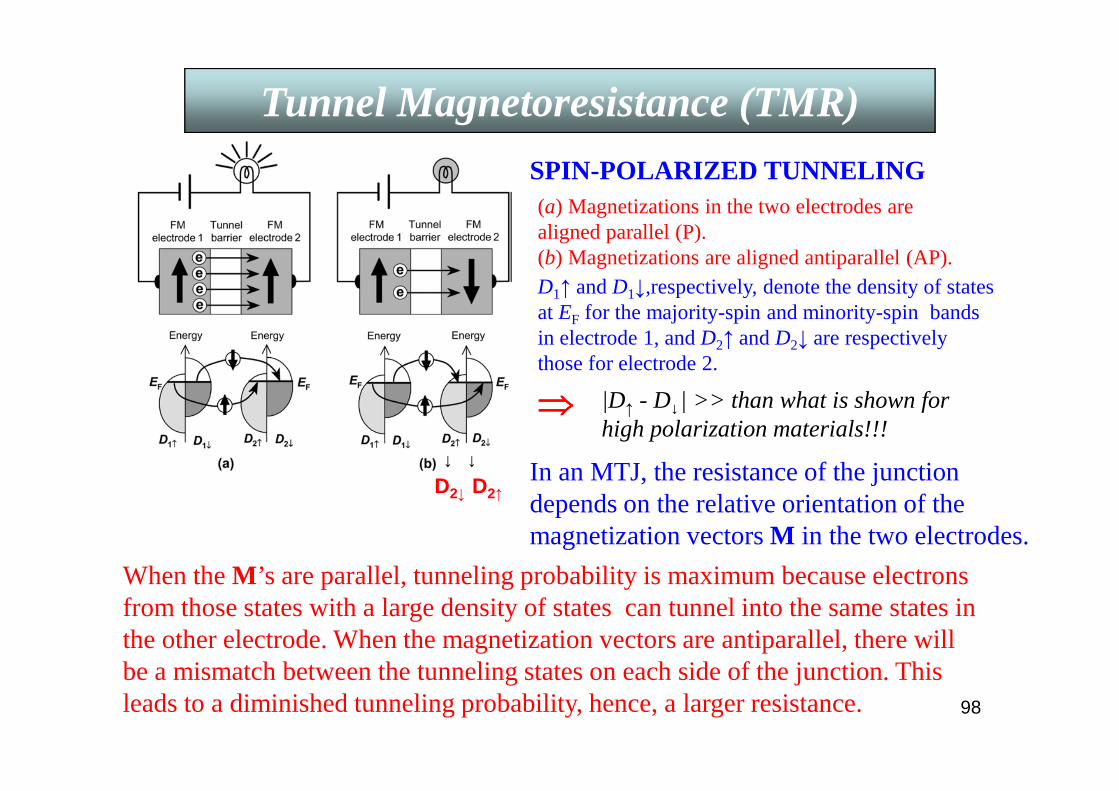
(a) Magnetizations in the two electrodes are aligned parallel (P).(b) Magnetizations are aligned antiparallel (AP).
D2↓ D2↑
↓ ↓
SPIN-POLARIZED TUNNELING
In an MTJ, the resistance of the junction depends on the relative orientation of the magnetization vectors M in the two electrodes.
When the M’s are parallel, tunneling probability is maximum because electrons from those states with a large density of states can tunnel into the same states in the other electrode. When the magnetization vectors are antiparallel, there will be a mismatch between the tunneling states on each side of the junction. This leads to a diminished tunneling probability, hence, a larger resistance.
D1↑ and D1↓,respectively, denote the density of states at EF for the majority-spin and minority-spin bands in electrode 1, and D2↑ and D2↓ are respectively those for electrode 2.
|D↑ - D↓| >> than what is shown for high polarization materials!!!
⇒⇒⇒⇒
99
Tunnel Magnetoresistance (TMR)
Gang Mao, Gupta, el al. at Brown & IBM obtained below 200 Oe a GMR of 250 % in MTJ’s with electrodes made of epitaxial films ofdoped half-metallic manganite La0.67Sr033MnO3 (LSMO) and insulating barrier of SrTiO3 using self-aligned lithographic process to pattern the junctions to micron size. They confirmed the spin-polarized tunneling as the active mechanism with P ~ 0.75. The low saturation field comes from the fact that manganites are magnetically soft, having a coercive field as small as 10 Oe. They have also made polycrystalline films with a large number of the grain boundaries and observed large MR at low fields. Here the mechanism has been attributed to the spin-dependent scattering across the grain boundaries that serves to pin the magnetic domain walls.
Assuming no spin-flip scattering, the MR ratio between the two configurations is given by,(∆R/RP ) = (RAP - RP)/RP = 2P2/(1-P2 ), where RP/RAP is the resistance for the P/AP configuration & P = (D↑ – D↓)/ (D↑ + D↓) = spin-polarization parameter of the magnetic electrodes. A half-metal corresponds to P = 1.

100
Another class of materials, the rare-earth manganite oxides, La1-xDxMnO3 (D = Sr, Ca, etc.), show Colossal Magnetoresistance effect (CMR) with a very large negative MR near their magnetic phase transition temperatures (TC) when subjected to a tesla-scale magnetic field.
The double-exchangemodel of Zener and a strong e-ph interaction from the Jahn-Tellersplitting of Mn d levels explain most of their magnetotransport properties.
Though fundamentally interesting, the CMR effect, achieved only at large fields and below 300 K, poses severe technological challenges to potential applications in magnetoelectronic devices, where low field sensitivity is crucial.
Colossal Magnetoresistance (CMR)

101
Colossal Magnetoresistance (CMR)
102
Colossal Magnetoresistance (CMR)
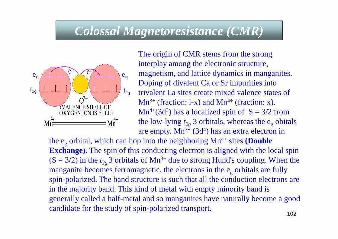
the eg orbital, which can hop into the neighboring Mn4+ sites (Double Exchange). The spin of this conducting electron is aligned with the local spin (S = 3/2) in the t2g3 orbitals of Mn3+ due to strong Hund's coupling. When the manganite becomes ferromagnetic, the electrons in the eg orbitals are fully spin-polarized. The band structure is such that all the conduction electrons are in the majority band. This kind of metal with empty minority band is generally called a half-metal and so manganites have naturally become a good candidate for the study of spin-polarized transport.
The origin of CMR stems from the strong interplay among the electronic structure, magnetism, and lattice dynamics in manganites. Doping of divalent Ca or Sr impurities into trivalent La sites create mixed valence states of Mn3+ (fraction: l-x) and Mn4+ (fraction: x). Mn4+(3d3) has a localized spin of S = 3/2 from the low-lying t2g 3 orbitals, whereas the eg obitals are empty. Mn3+ (3d4) has an extra electron in
t2g
eg
t2g
eg
103
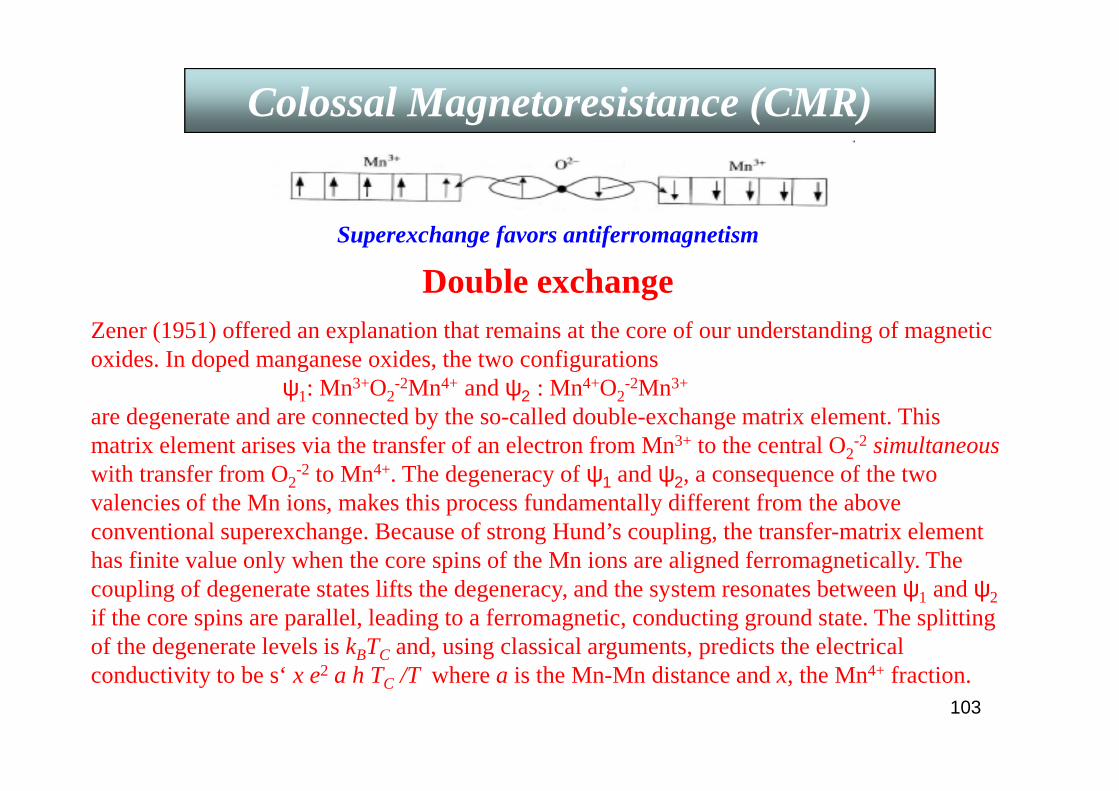
Colossal Magnetoresistance (CMR)
Superexchange favors antiferromagnetism
Double exchangeZener (1951) offered an explanation that remains at the core of our understanding of magnetic oxides. In doped manganese oxides, the two configurations
ψ1: Mn3+O2-2Mn4+ and ψ2 : Mn4+O2
-2Mn3+
are degenerate and are connected by the so-called double-exchange matrix element. This matrix element arises via the transfer of an electron from Mn3+ to the central O2-2 simultaneous with transfer from O2-2 to Mn4+. The degeneracy of ψ1 and ψ2, a consequence of the two valencies of the Mn ions, makes this process fundamentally different from the above conventional superexchange. Because of strong Hund’s coupling, the transfer-matrix element has finite value only when the core spins of the Mn ions are aligned ferromagnetically. The coupling of degenerate states lifts the degeneracy, and the system resonates between ψ1 and ψ2
if the core spins are parallel, leading to a ferromagnetic, conducting ground state. The splitting of the degenerate levels is kBTC and, using classical arguments, predicts the electrical conductivity to be s‘ x e2 a h TC /T where a is the Mn-Mn distance and x, the Mn4+ fraction.

Thanks