magnetostrictive liquid-level transmitters with ... · magnetostrictive liquid-level transmitters...
TRANSCRIPT

Liquid-Level Transmitter AccessoriesCatalog
Level Plus®
Magnetostrictive Liquid-Level Transmitterswith Temposonics Technology

2
Accessories Overview .....................................................................................................................................................................................................3
FloatsStandard Floats ...............................................................................................................................................................................................................4
Standard Product Floats ...........................................................................................................................................................................................4Low-liftoff Float ........................................................................................................................................................................................................5 Standard Interface Floats .........................................................................................................................................................................................6
Sanitary Floats ................................................................................................................................................................................................................7Teflon Floats ....................................................................................................................................................................................................................9Nitrophyl® Floats ...........................................................................................................................................................................................................10Long-Gauge Floats ........................................................................................................................................................................................................11
Process Meters and EnclosuresAnalog Process Meters .................................................................................................................................................................................................13Modbus Process Meters ...............................................................................................................................................................................................14Process Meter Enclosures.............................................................................................................................................................................................15Modbus Terminals ........................................................................................................................................................................................................15
Programming and HardwareProgramming Accessories ............................................................................................................................................................................................16Setup Software .............................................................................................................................................................................................................16Hardware ......................................................................................................................................................................................................................16
Magnets and Weight AssembliesMagnets and Weight Assemblies ..................................................................................................................................................................................17
TABLE OF CONTENTS

3
FEATURES
X Variety of Styles and Sizes to Fit Most Applications X Available in 316L Stainless Steel, Aluminum, Teflon®,
Hastelloy® C and Nitrophyl® X Custom Weighting Available
APPLICATIONS
X Custody Transfer X Inventory Control X Bulk Storage X Sanitary Process Control
MARKETS
X Petroleum and Petrochemical X LPG Terminals X Biotech and Pharmaceutical X Food and Beverage X Waste and Wastewater
MTS Offers a Variety of Liquid-Level Product Accessories
MTS Sensors offers a variety of floats to meet your application needs. Our floats come in a variety of sizes from less than 38 mm (1.5 in.) up to 178 mm (7 in.) in diameter. Float materials are available in stainless steel, Teflon®, Aluminum, Hastelloy® C and Nitrophyl®.
Product viscosity, specific gravity, and temperature can vary widely in a process or tank gauging application. Because of these variables and others, such as tank pressure and corrosiveness, no one float can meet all requirements. Therefore, a variety of float styles are available and we will assist you in choosing the one that best meets your requirements.
When choosing a float for your application, MTS recommends you choose one that has a specific gravity of at least 0.05 less than that of the measured liquid. For interface measurement, a minimum of 0.05 specific gravity differential is recommended between upper and lower liquids.
MTS Sensors also offers a variety of meters, housings, and calibration equipment as accessories to our transmitter range. Meters are avail-able for analog, DDA, and Modbus outputs.
For more information, please contact the MTS Sensors’ applications department or go to www.mtssensors.com for more information.
ACCESSORIES OVERVIEW

4
STANDARD FLOATS
Float and dimension reference Pressure Temp. Magnet offset Specific gravity Material Part number
18 mm(0.7 in.) dia.
47 mm(1.85 in.) dia.
77 mm(3.01 in.) 29.3 bar
(425 psi)149 °C
(300 ºF)No
0.67 SS 251981-2*
0.71 Hastelloy®-C 251981-4
18 mm (0.7 in.) dia.
57 mm(2.22 in.)
59 mm (2.32 in.) dia.
22.4 bar(325 psi)
149 °C (300 ºF)
No 0.48 SS 251387-2
18 mm (0.7 in.) dia.
50 mm(1.96 in.)
47 mm(1.83 in.) dia.
54 mm(2.11 in.) 4 bar
(60 psi)149 °C
(300 ºF)Yes 0.6 SS 201605-2*
General Notes:
1. Be sure that the float specific gravity is at least 0.05 less than that of the measured liquid as a safety margin at ambient temperature. 2. For interface measurement: A minimum of 0.05 specific gravity differential is required between the upper and lower liquids. 3. When the magnet is not shown, the magnet is positioned at the center line of float.4. Drawings contained in this document are for reference only. Contact the factory for engineering drawings.5. *Standard float that can be expedited

5
Float and dimension reference Pressure Temp. Magnet offset Specific gravity Material Part number
69 bar(1000 psi)
149 °C (300 ºF)
No 0.65 SS 254526-2*
18 mm (0.7 in.) dia.
89 mm (3.5 in.) dia.
91 mm(3.57 in.) 22.4 bar
(325 psi)149 °C
(300 ºF)No 0.45 SS 251469-2
Float and dimension reference Pressure Temp. Magnet offset Specific gravity Material Part number
26 mm(1 in.)
76 mm(3 in.)
18 mm (0.7 in.) I.D. min. 102 mm
(4.0 in.) O.D.
39 mm(1.52 in.)
Magnet
38 mm(1.5 in.)
15 mm(0.57 in.) Ref
8.6 bar(125 psi)
149 °C (300 ºF)
Yes 0.65 SS 252228-4
STANDARD FLOATS
LOW-LIFTOFF FLOATS
DETAIL BSCALE 2 : 1
1
1
2
2
3
3
4
4
A A
B B
REV ECO # DESCRIPTION
TITLE
SIZE DWG NO. REV
PRODUCT LINESCALE:
BY DATE CHK BY APPR BY
SHEET OF
UNLESS OTHERWISE SPECIFIEDTOLERANCES
2 PLACESINCHES
3 PLACESINCHES
ANGLES���� .01 � .005
THREAD DEPTHS ARE TO MIN. FULL THDSDRILL DEPTHS ARE TO FULL DIA.REMOVE BURRS AND SHARP EDGESDO NOT SCALE PRINTMACHINED SURFACE FINISH 125
PROPRIETARY DATATHE INFORMATION AND DESIGN(S) DISCLOSEDHEREIN ARE THE PROPERTY OF MTS SYSTEMSCORPORATION AND MAY NOT BE USED,REPRODUCED OR DISCLOSED IN ANY FORMEXCEPT AS GRANTED IN WRITING BY MTSSYSTEMS CORPORATION. THIS RESTRICTIONEXCLUDES INFORMATION THAT IS IN THE PUBLIC DOMAIN OR WAS LEGITIMATELY IN THEPRIOR POSSESSION OF THE RECIPIENT.
mMTS SYSTEMS CORPORATIONSENSORS DIVISION3001 SHELDON DRIVE, CARY, NC 27513
THIRDANGLE B 254526- A
LL1 1
ACP FLOAT 1.85" OD 70 BAR (1,220 PSIG)
DRAWN BY: DR1:1
A 7634 RELEASE TO PRODUCTION DR 1/6/14
**NO REVISIONS SHALL BE MADE WITHOUT NOTIFICATION OF APPROVAL AGENCY(S).**
A
A
2.820
MAGNET 401467
MAGNET RETAINER (2X)SEE NOTE 1
CHARTDASH NUMBER MATERIAL VARIATION WEIGHT RANGE SPECIFIC GRAVITY AGENCY
DELLORTNOC TON56.4.05THGIEW TESFFO TUOHTIWLEETS SSELNIATS l613/61312 TNAILPMOC-XETA56.4.05THGIEW TESFFO HTIWLEETS SSELNIATS l613/613
MTSP/N 254526-X
SG .65
D96 LASER ENGRAVEMTS PART NUMBER,SPECIFIC GRAVITY &
DATE CODE
NOTES: 1. RESISTANCE WELD EACH RETAINER TO I.D. TUBE.2. ALL JOINTS WELDED MUST NOT LEAK OR COLLAPSE IN 1300 PSIG EXTERNAL PRESSURE. WORKING PRESSURE IS 1,220 PSIG.3. WEIGHT: SEE CHART (GRAMS)4. DISPLACEMENT: 4.8 CU IN. NORMAL.5. UNLESS OTHERWISE SPECIFIED, ALL PART NUMBERS ARE INNOVATIVE FUSION.6. MAGNET TO BE BONDED NEODYMIUM APPROVED VENDOR: ARNOLD ENGINEERING.7. SEE CHART FOR SPECIFIC GRAVITITES OF FLOAT.8. FOR OFFSET OPTION: ATTACH OFFSET WEIGHT INSIDE FLOAT FOR ATEX APPLICATIONS. AMOUNT OF WEIGHT TO ENSURE FLOAT I.D. TUBE CONTACT WITH GAUGE TUBE.9. VENDOR TO ATTACH MATERIAL CERTIFICATION TO VERIFY THAT THE SPECIFIED MATERIAL OR ITS GRADE EQUIVALENT WAS USED.10. LASER ETCH THE FOLLOWING INFORMATION ON THE FLOAT. MTS (ABOVE CENTERLINE OF FLOAT) PART NUMBER: BELOW MTS BUT ABOVE CENTERLINE OF FLOAT SPECIFIC GRAVITY: BELOW CENTERLINE OF FLOAT. DATE CODE CONSIST OF ALPHANUMERIC CHARACTER FOR THE MONTH AND FOLLOWED BY THE YEAR.11. NO SCRATCHES, DENTS, OR CREVICES ALLOWED.12. FLOAT LUSTER TO MATCH PROVIDED SAMPLE.13. PACKAGE TO PREVENT DAMAGE DURING SHIPPING AND HANDLING.14. REFERENCE: PROJECTED SURFACE AREA = 4.541² INCHES (2929.79² mm)
FULL SPHERICAL RAD (TYP)18 mm I.D.
( 0.700 MIN I.D.)
72 mm (2.82 in.)
47 mm O.D.( 1.85 MIN O.D.)
Ø
Ø
6
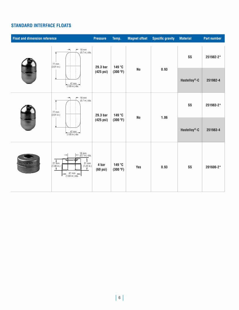
STANDARD INTERFACE FLOATS
Float and dimension reference Pressure Temp. Magnet offset Specific gravity Material Part number
18 mm(0.7 in.) dia.
47 mm(1.85 in.) dia.
77 mm(3.01 in.) 29.3 bar
(425 psi)149 °C
(300 ºF)No 0.93
SS 251982-2*
Hastelloy®-C 251982-4
18 mm(0.7 in.) dia.
47 mm(1.85 in.) dia.
77 mm(3.01 in.) 29.3 bar
(425 psi)149 °C
(300 ºF)No 1.06
SS 251983-2*
Hastelloy®-C 251983-4
18 mm(0.7 in.) dia.
31 mm(1.22 in.)
27 mm(1.06 in.)
47 mm
(1.83 in.) dia.
4 bar(60 psi)
149 °C (300 ºF)
Yes 0.93 SS 201606-2*
7
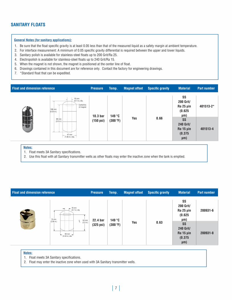
SANITARY FLOATS
General Notes (for sanitary applications):
1. Be sure that the float specific gravity is at least 0.05 less than that of the measured liquid as a safety margin at ambient temperature. 2. For interface measurement: A minimum of 0.05 specific gravity differential is required between the upper and lower liquids. 3. Sanitary polish is available for stainless-steel floats up to 200 Grit/Ra 25. 4. Electropolish is available for stainless-steel floats up to 240 Grit/Ra 15.5. When the magnet is not shown, the magnet is positioned at the center line of float. 6. Drawings contained in this document are for reference only. Contact the factory for engineering drawings.7. *Standard float that can be expedited.
Notes:1. Float meets 3A Sanitary specifications. 2. Use this float with all Sanitary transmitter wells as other floats may enter the inactive zone when the tank is emptied.
Notes:1. Float meets 3A Sanitary specifications. 2. Float may enter the inactive zone when used with 3A Sanitary transmitter wells.
Float and dimension reference Pressure Temp. Magnet offset Specific gravity Material Part number
18 mm(0.7 in.) dia.
47 mm(1.85 in.) dia.
Centerline of magnet
89 mm(3.5 in.)
108 mm(4.25 in.)
10.3 bar(150 psi)
149 °C (300 ºF)
Yes 0.66
SS200 Grit/Ra 25 μin
(0.625μm)
401513-2*
SS240 Grit/Ra 15 μin
(0.375μm)
401513-4
Float and dimension reference Pressure Temp. Magnet offset Specific gravity Material Part number
18 mm(0.7 in.) dia.
60 mm(2.34 in.) dia.
75 mm(2.95 in.) CL
64 mm(2.5 in.)
22.4 bar(325 psi)
149 °C (300 ºF)
Yes 0.63
SS200 Grit/Ra 25 μin
(0.625μm)
200931-6
SS240 Grit/Ra 15 μin
(0.375μm)
200931-8

8
SANITARY FLOATS (CONTINUED)
Notes:1. Float meets clean-in-place and drain-in-place applications.2. Float may enter the inactive zone. Consult factory about viability of usage.
Notes:1. Float meets 3A Sanitary specifications.2. Float meets clean-in-place and drain-in-place applications. 3. Float may enter the inactive zone. Consult factory about viability of usage.
Float and dimension reference Pressure Temp. Magnet offset Specific gravity Material Part number
51 mm(2 in.) dia.
Over weld bead
Magnet
25 mm(.98 in.)
48 mm(1.9 in.)
102 mm(4.02 in.)
41 mm(1.6 in.)
18 mm(.7 in.) I.D.Min.92 mm
(3.6 in.) dia.
8.6 bar(125 psi)
149 °C (300 ºF)
Yes 0.48
SS240 Grit/Ra 15 μin
(0.375μm)
252228-2
Float and dimension reference Pressure Temp. Magnet offset Specific gravity Material Part number
Magnetposition
L
73 mm(2.85 in.) dia.
C
56 mm(2.21 in.)
80 mm(3.15 in.) dia.
R.157 (4) Min.
23 mm(.9 in.) dia.
64 bar(928 psi)
149 °C (300 ºF)
Yes 0.86
SS240 Grit/Ra 15 μin
(0.375μm)
560564-2
Float and dimension reference Pressure Temp. Magnet offset Specific gravity Material Part number
Magnet
18 mm(0.7 in.)Min I.D.
25 mm (.98 in.)51 mm
(2 in.) O.D.Over weld bead
50 mm (1.96 in.)22.4 bar(325 psi)
149 °C (300 ºF)
No 0.74
SS200 Grit/Ra 25 μin
(0.625μm)
251234-2
Notes:
Use this float with all Sanitary transmitter wells as other floats may enter the inactive zone when the tank is emptied.
9
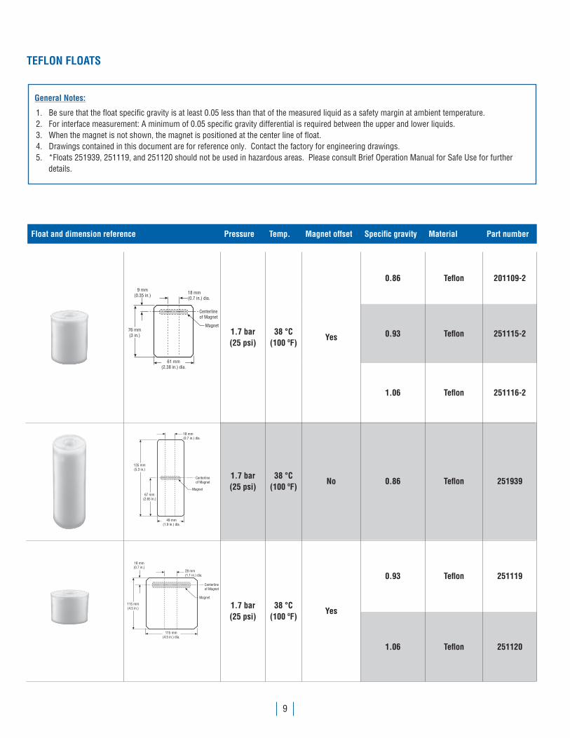
TEFLON FLOATS
General Notes:
1. Be sure that the float specific gravity is at least 0.05 less than that of the measured liquid as a safety margin at ambient temperature. 2. For interface measurement: A minimum of 0.05 specific gravity differential is required between the upper and lower liquids. 3. When the magnet is not shown, the magnet is positioned at the center line of float. 4. Drawings contained in this document are for reference only. Contact the factory for engineering drawings.5. *Floats 251939, 251119, and 251120 should not be used in hazardous areas. Please consult Brief Operation Manual for Safe Use for further details.
Float and dimension reference Pressure Temp. Magnet offset Specific gravity Material Part number
61 mm(2.38 in.) dia.
76 mm(3 in.)
9 mm(0.35 in.)
Magnet
Centerlineof Magnet
18 mm(0.7 in.) dia.
1.7 bar(25 psi)
38 °C (100 ºF)
Yes
0.86 Teflon 201109-2
0.93 Teflon 251115-2
1.06 Teflon 251116-2
67 mm(2.65 in.)
49 mm(1.9 in.) dia.
Magnet
Centerlineof Magnet
18 mm(0.7 in.) dia.
135 mm(5.3 in.)
1.7 bar(25 psi)
38 °C (100 ºF)
No 0.86 Teflon 251939
115 mm(4.5 in.) dia.
115 mm(4.5 in.)
18 mm(0.7 in.)
Magnet
Centerlineof Magnet
28 mm(1.1 in.) dia.
1.7 bar(25 psi)
38 °C (100 ºF)
Yes
0.93 Teflon 251119
1.06 Teflon 251120
10
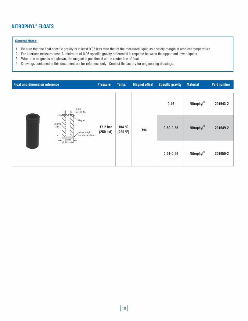
NITROPHYL® FLOATS
General Notes:
1. Be sure that the float specific gravity is at least 0.05 less than that of the measured liquid as a safety margin at ambient temperature. 2. For interface measurement: A minimum of 0.05 specific gravity differential is required between the upper and lower liquids. 3. When the magnet is not shown, the magnet is positioned at the center line of float. 4. Drawings contained in this document are for reference only. Contact the factory for engineering drawings.
Float and dimension reference Pressure Temp. Magnet offset Specific gravity Material Part number
18 mm(.07 in.) dia.
Magnet
CL
76 mm(3 in.)
31 mm(1.2 in.) dia.
Added weightfor interface floats
17.2 bar(250 psi)
104 °C (220 ºF)
Yes
0.45 Nitrophyl® 201643-2
0.80-0.86 Nitrophyl® 201649-2
0.91-0.96 Nitrophyl® 201650-2

11
LONG-GAUGE FLOATS
General Notes:
1. Be sure that the float specific gravity is at least 0.05 less than that of the measured liquid as a safety margin at ambient temperature. 2. For interface measurement: A minimum of 0.05 specific gravity differential is required between the upper and lower liquids. 3. When the magnet is not shown, the magnet is positioned at the center line of float. 4. Drawings contained in this document are for reference only. Contact the factory for engineering drawings.5. *Standard float that can be expedited.
Float and dimension reference Pressure Temp. Magnet offset Specific gravity Material Part number
L
92 mm(3.6 in.) dia.
76 mm(3 in.)
88 mm(3.44 in.)
C Magnet
28 mm(1.1 in.)dia.
29.3 bar(425 psi)
149 °C (300 ºF)
Yes
0.54 SS 252961-2*
0.65 Hastelloy®-C 252961-4
0.93 SS 252962-2
0.93 Hastelloy®-C 252962-4
1.06 SS 252963-2
1.06 Hastelloy®-C 252963-4
130 mm(5.11 in.)
127 mm(4.98 in.)
116 mm(4.55 in.)
28 mm (1.1 in.)
CL Magnet
44.8 bar(650 psi)
149 °C (300 ºF)
Yes
0.44 SS 201248-2
0.52 Hastelloy®-C 201248-4
0.93 SS 252959-2
0.93 Hastelloy®-C 252959-4
1.06 SS 252960-2
1.06 Hastelloy®-C 252960-4

12
LONG-GAUGE FLOATS (CONTINUED)
Float and dimension reference Pressure Temp. Magnet offset Specific gravity Material Part number
48 mm(1.9 in.)
I.D.
6.95 in.(00.0 mm)
178 mm(7 in.)
178 mm (7 in.)
17.2 bar(250 psi)
149 °C (300 ºF)
No
0.44 SS 251426-2
0.47 Hastelloy®-C* 251426-4
0.93 SS 251427-2
0.93 Hastelloy®-C* 251427-4
1.06 SS 251428-2
28 mm(1.1 in.) dia.
127 mm(5.01 in.)
70 mm(2.76 in.) max. dia.
22.4 bar(325 psi)
149 °C (300 ºF)
No
0.66 SS 201232-2*
0.70 Hastelloy®-C 201232-4
0.93 SS 201233-2
* Internal Diameter for these floats is 34.8 mm (1.37 in.).
13
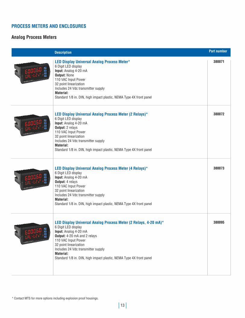
PROCESS METERS AND ENCLOSURES
Analog Process Meters
Description Part number
LED Display Universal Analog Process Meter*6 Digit LED displayInput: Analog 4-20 mAOutput: None110 VAC Input Power32 point linearizationIncludes 24 Vdc transmitter supplyMaterial:Standard 1/8 in. DIN, high impact plastic, NEMA Type 4X front panel
380071
LED Display Universal Analog Process Meter (2 Relays)*6 Digit LED displayInput: Analog 4-20 mAOutput: 2 relays110 VAC Input Power32 point linearizationIncludes 24 Vdc transmitter supplyMaterial:Standard 1/8 in. DIN, high impact plastic, NEMA Type 4X front panel
380072
LED Display Universal Analog Process Meter (4 Relays)*6 Digit LED displayInput: Analog 4-20 mAOutput: 4 relays110 VAC Input Power32 point linearizationIncludes 24 Vdc transmitter supplyMaterial:Standard 1/8 in. DIN, high impact plastic, NEMA Type 4X front panel
380073
LED Display Universal Analog Process Meter (2 Relays, 4-20 mA)*6 Digit LED displayInput: Analog 4-20 mAOutput: 4-20 mA and 2 relays110 VAC Input Power32 point linearizationIncludes 24 Vdc transmitter supplyMaterial:Standard 1/8 in. DIN, high impact plastic, NEMA Type 4X front panel
380095
* Contact MTS for more options including explosion proof housings.
14
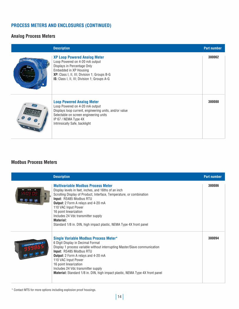
Modbus Process Meters
Description Part number
XP Loop Powered Analog Meter Loop Powered on 4-20 mA outputDisplays in Percentage OnlyEmbedded in XP HousingXP: Class I, II, III; Division 1; Groups B-GIS: Class I, II, III; Division 1; Groups A-G
380062
Loop Powered Analog Meter Loop Powered on 4-20 mA outputDisplays loop current, engineering units, and/or valueSelectable on screen engineering unitsIP 67 / NEMA Type 4XIntrinsically Safe, backlight
380088
Description Part number
Multivariable Modbus Process MeterDisplay levels in feet, inches, and 16ths of an inchScrolling Display of Product, Interface, Temperature, or combinationInput: RS485 Modbus RTUOutput: 2 Form A relays and 4-20 mA110 VAC Input Power16 point linearizationIncludes 24 Vdc transmitter supplyMaterial:Standard 1/8 in. DIN, high impact plastic, NEMA Type 4X front panel
380086
Single Variable Modbus Process Meter* 6 Digit Display in Decimal FormatDisplay 1 process variable without interrupting Master/Slave communicationInput: RS485 Modbus RTUOutput: 2 Form A relays and 4-20 mA110 VAC Input Power16 point linearizationIncludes 24 Vdc transmitter supplyMaterial: Standard 1/8 in. DIN, high impact plastic, NEMA Type 4X front panel
380094
* Contact MTS for more options including explosion proof housings.
PROCESS METERS AND ENCLOSURES (CONTINUED)
Analog Process Meters

15
Modbus Terminals
Description Part number
NEMA Enclosures†
Single NEMA 4X
Dual NEMA 4X
† NEMA Enclosures are available for most process meters, please contact factory for more information.
401150
401151
Description Part number
LCD Modbus TerminalDisplays up to 4 tanks (2 levels, temp, volume)Displays up to 8 tanks (2 levels, temp)Displays levels in ft., in, and 16ths in.Input: Up to 8 Modbus transmittersOutput: ModbusMounted in NEMA 4 boxClass 1 Div. 2Includes Power SupplyCalibrate from Screen
280494-X
Touchscreen Modbus TerminalDisplays up to 16 tanks (2 levels, temp, volume)Displays levels in ft., in, and 16ths in.Input: up to 16 Modbus transmittersOutput: ModbusPictorial display of tanksTouchscreenMounted in NEMA 4 boxClass 1 Div. 2Includes Power SupplyCalibrate from Screen
280508-X
PROCESS METERS AND ENCLOSURES (CONTINUED)
Process Meter Enclosures
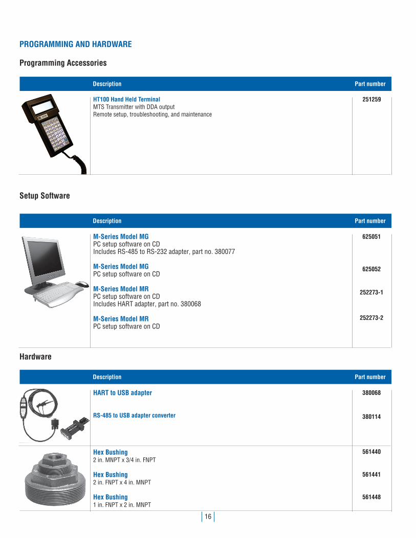
16
Setup Software
Hardware
Description Part number
HT100 Hand Held TerminalMTS Transmitter with DDA outputRemote setup, troubleshooting, and maintenance
251259
Description Part number
M-Series Model MGPC setup software on CDIncludes RS-485 to RS-232 adapter, part no. 380077
M-Series Model MGPC setup software on CD
M-Series Model MRPC setup software on CDIncludes HART adapter, part no. 380068
M-Series Model MRPC setup software on CD
Description Part number
HART to USB adapter
RS-485 to USB adapter converter
Hex Bushing2 in. MNPT x 3/4 in. FNPT
Hex Bushing2 in. FNPT x 4 in. MNPT
Hex Bushing1 in. FNPT x 2 in. MNPT
PROGRAMMING AND HARDWARE
Programming Accessories
625051
380068
380114
625052
561440
252273-1
561441
252273-2
561448

17
Description Part num-
51 mm(2 in.)
76 mm(3 in.)
150 lb. Pull MagnetFor LDF long transmitter and M-Series transmitters. (Top ring must be removed before installation)
560604
51 mm(2 in.)
127 mm(5 in.)
Standard 11 lb. WeightFor M-Series transmitters
401059
A
A
191 mm(7.5 in.) dia.
165 mm(6.5 in.) dia.
Section A-A
84 mm(3.3 in.) 3 mm
( .13 in.)16 mm( .63 in.)
Low Liftoff 11 lb. Weight Assembly 402364
89 mm (3.5 in.) dia.
32 mm (1.25 in.)dia. (2X)
37 mm(1.44 in.)
115 mm(4.5 in.)
64 mm(2.5 in.)
21 mm(.81 in.) dia.
1.3 X 45˚Chamfer
Narrow 11 lb. WeightUse with M-Series transmitters
402647
MAGNET AND WEIGHT ASSEMBLIES

MTS, Temposonics and Level Plus are registered trademarks of MTS Systems Corporation in the United States; MTS SENSORS and the MTS SENSORS logo are trademarks of MTS Systems Corporation within the United States. These trademarks may be protected in other countries. All other trademarks are the property of their respective owners. Copyright © 2017 MTS Systems Corporation. No license of any intellectual property rights is granted. MTS reserves the right to change the information within this document, change product designs, or withdraw products from availability for purchase without notice. Typographic and graphics errors or omissions are unintentional and subject to correction. Visit www.mtssensors.com for the latest product information. LO
CATI
ONS
LEGA
L NO
TICE
SUSAMTS Systems CorporationSensors Division3001 Sheldon DriveCary, N.C. 27513, USATel. +1 919 677-0100Fax +1 919 [email protected]
JAPANMTS Sensors Technology Corp.737 Aihara-machi, Machida-shi, Tokyo 194-0211, JapanTel. + 81 42 775-3838Fax + 81 42 775- [email protected]
ITALYMTS Systems Srl.Sensor DivisionVia Diaz,425050 Provaglio d‘Iseo (BS), ItalyTel. + 39 030 988 3819Fax + 39 030 982 [email protected]
GERMANYMTS Sensor TechnologieGmbH & Co. KGAuf dem Schüffel 958513 Lüdenscheid, GermanyTel. + 49 2351 9587-0Fax + 49 2351 [email protected]
CHINAMTS Sensors Room 504, Huajing Commercial Center, No. 188, North Qinzhou Road200233 Shanghai, ChinaTel. +86 21 6485 5800 Fax +86 21 6495 [email protected]
FRANCEMTS Systems SASZone EUROPARC Bâtiment EXA 1616/18, rue Eugène Dupuis94046 Creteil, FranceTel. + 33 1 58 4390-28Fax + 33 1 58 [email protected]
MTS has a dedicated expert support team who are available to assist with your specific application needs.1-800-633-7609 / [email protected]
Document Part Number:551103 Revision G (EN) 4/2017
FMAPPROVED