magnetventile für blockeinbau - airline hydraulics | products ... nas 1638, klasse 10; iso/dis...
TRANSCRIPT

Magnetventile für Blockeinbau
Cartridge solenoid valves
Electro-distributeurs type cartouche
Fahrzeughydraulik
Mobile Hydraulics
Hydraulique mobile
11
Automationstechnik

Magnet-Schieberventile Seite 16 ... 30für Blockeinbau
Cartridge type solenoid Page 16 ... 30spool valves
Electro-distributeurs Page 16 ... 30à tiroir
type cartouche
Magnet-Sitzventile Seite 3 ... 15für Blockeinbau
Cartridge type solenoid Page 3 ... 15check valves
Electro-distributeurs Page 3 ... 15à clapet
type cartouche

Magnet-Sitzventile / Solenoid check valves / Electro-distrib. à clapet 3æ
Magnet-Sitzventilefür Blockeinbau
Cartridge typesolenoidcheck valves
Electro-distributeursà clapettype cartouche
SinnbildSymbolSymbole
P DIN/ISO KOSTAL JET[W] 1) 2) 1) 2) 1) m[kg] «
1 212 V= 31 M 20 x 1,5 P 0,36 0 810 040 909
P P 0,45 0 810 040 918
P P 0,36 0 810 040 907
3/4–16 UNF-2A P 0,42 0 810 040 932
224 V= M 20 x 1,5 P 0,36 0 810 040 910
P P 0,45 0 810 040 919
P P 0,51 0 810 040 908
3/4–16 UNF-2A P 0,42 0 810 040 933
248 V= M 20 x 1,5 P 0,36 0 810 040 928
205 V= P 0 810 040 913
2 212 V= 31 M 20 x 1,5 P 0,36 0 810 040 917
P P 0 810 040 931
224 V= P 0 810 040 929
3 212 V= 31 M 20 x 1,5 P 0,48 0 810 040 951
P P 0 810 040 949
P 0,74 0 810 040 957
P 0,48 0 810 040 947
P 0 810 040 953
33 P 0,74 0 810 040 960
224 V= 31 P 0,48 0 810 040 952
P 0,74 0 810 040 958
P P 0,48 0 810 040 950
P 0 810 040 962
P 0 810 040 954
33 P 0,74 0 810 040 961
205 V= 35 P 0 810 040 9591) Steckdose nicht enthalten / Plug connector not included / Connecteur non inclus2) Steckdose enthalten / Plug connector included / Connector inclus3) Bidirektionale Doppel-Z-Diode / Bidirectional double Zener diode / Diode Z double bidirectionnelle
Bi-D
iod
e3)

4 Magnet-Sitzventile / Solenoid check valves / Electro-distrib. à clapet æFunktion
1 Sitzventil vorgesteuert
Magnet stromlos:A R P gesperrtP R A offen, ∆p = 2 bar*)Magnet erregt:A R P offen, ∆p = 1 bar*)P R A gedrosselt
2 Sitzventil vorgesteuert
Magnet stromlos:A R P gesperrtP R A offen, ∆p = 2 bar*)Magnet erregt:A R P offen, ∆p = 1 bar*)P R A offen, ∆p = 2 bar*)
3 Sitzventil direkt gesteuert
Magnet stromlos:A R P und P R A gesperrtin beiden RichtungenMagnet erregt:A R P und P R A offen
*) ∆p: Öffnungsdrücke sindZirka-Werte
Hinweis: Bei Verwendung der Ven-tile mit elektrischem Anschluß nachSchutzklasse III (ohne Schutzleiter)sind die Schutzmaßnahmen nachDIN VDE 0100, Teil 410 und DIN VDE 0106, Teil 100 einzuhalten.
Function
1 Poppet-type valve pilot
operated
Solenoid not energized:A R P closedP R A open, ∆p = 2 bar*)Solenoid energized:A R P open, ∆p = 1 bar*)P R A throtteled
2 Poppet-type valve pilot
operated
Solenoid not energized:A R P closedP R A open, ∆p = 2 bar*)Solenoid energized:A R P open, ∆p = 1 bar*)P R A open, ∆p = 2 bar*)
3 Poppet-type valve direct
operated
Solenoid not energized:A R P and P R A closed.Leak tight both directions.Solenoid not energized:A R P and P R A open
*) ∆p: Opening pressure approx.
Note: When using valves with anelectrical connection which con-forms to protection class III (withoutPE conductor), protective measuresto DIN VDE 0100, part 410 andDIN VDE 0106, part 100, must be complied with.
Fonctionnement
1 Distributeur à clapet piloté
Bobine non excitée:A R P ferméP R A ouvert, ∆p = 2 bar*)Bobine excitée:A R P ouvert, ∆p = 1 bar*)P R A débit réduit
2 Distributeur à clapet piloté
Bobine non excitée:A R P ferméP R A ouvert, ∆p = 2 bar*)Bobine excitée:A R P ouvert, ∆p = 1 bar*)P R A ouvert, ∆p = 2 bar*)
3 Distributeur à clapet
à commande directe
Bobine non excitée:A R P et P R A ferméétanche dans les deux sens.Bobine excitée:A R P et P R A ouvert
*) ∆p: Pression d’ouvertureapproxim.
Remarque: En cas d’utilisation devalves avec raccord électrique con-forme à la classe de protection III(sans conducteur de protection), il faut respecter les mesures de protection selon DIN VDE 0100, partie 410 et DIN VDE 0106, partie 100.

Magnet-Sitzventile / Solenoid check valves / Electro-distrib. à clapet 5æKenngrößen
Bauart Sitzventil, elektrisch betätigt
Einbaulage beliebig
Umgebungstemperatur – 30 °C bis + 50 °C
Druckmittel Hydrauliköl auf Mineralölbasis nach DIN/ISO;andere, z. B. umweltschonende Medien auf Anfrage
Viskosität 10 bis 500 mm2/s
Druckmitteltemperatur – 25 °C bis + 80 °C
Filterung NAS 1638, Klasse 10; ISO/DIS 4406, Klasse 19/16;zu erreichen mit Filterfeinheit â25 ≥ 751)
Durchflußrichtung gemäß Sinnbild
Öffnungsdruck (Feder) siehe Seite 4
Sinnbild vorgesteuert direkt gesteuert1
1 32
Anschlußart Blockeinbau mit EinschraubgewindeM 20 x 1,5 3/4 – 16 UNF-2A M 20 x 1,5
Betriebsdruck 15 · 105 Lastwechsel 270 bar 210 bar 270 bar 270 bar
10 · 106 Lastwechsel 160 bar 160 bar 160 bar 210 bar
Maximaler Durchfluß 30 l/min 15 l/min 20 l/min 20 l/min
Magnetleistung 31 W 31 W 31 W 33 bis 35 W
Strom bei Nennspannung 12 V ± 20 % 2,6 A 2,6 A 2,6 A 2,75 A
24 V ± 20 % 1,3 A 1,3 A 1,3 A 1,4 A
S48 V ± 20 % 0,63 A – – –
205 V ± 10 % 0,15 A – – 0,17A
Einschaltdauer 100 %
Schutzart IP 65 DIN 40 050
Elektrischer Anschluß Winkelsteckdose DIN/ISO, KOSTAL oder JET
Funkenlöschung Bidirektionale Doppel-Z-Diode1) Rückhalterate für Schmutzteilchen > 25 µm ist 1 : 75, d. h. 98,67 %
Specifications
Design Poppet-type valve, electrically operated
Mounting position as desired
Ambient temperature – 30 °C to + 50 °C
Fluid Petroleum-based hydraulic fluid to DIN/ISO;optional fluids, e.g. environmentally-compatible media, on request
Viscosity 10 ... 500 mm2/s
Fluid temperature – 25 °C to + 80 °C
Filtration NAS 1638, class 10; ISO/DIS 4406, class 19/16;obtained with filter fineness â25 ≥ 751)
Direction of flow as shown on symbol
Opening pressure (spring) see page 4
Symbol pilot operated direct operated1
1 32
Mounting type Cartridge with threaded socketM 20 x 1,5 3/4 – 16 UNF-2A M 20 x 1,5
Operating pressure 5 · 105 load reversals 270 bar 210 bar 270 bar 270 bar
10 · 106 load reversals 160 bar 160 bar 160 bar 210 bar
Maximum flow 30 l/min 15 l/min 20 l/min 20 l/min
Solenoid power 31 W 31 W 31 W 33 to 35 W
Current at nominal voltage 12 V ± 20 % 2.6 A 2.6 A 2.6 A 2.75 A
24 V ± 20 % 1.3 A 1.3 A 1.3 A 1.4 A
48 V ± 20 % 0.63 A – – –
205 V ± 10 % 0.15 A – – 0.17A
Duty cycle 100 %
Degree of protection IP 65 DIN 40 050
Power supply Plug connector to DIN/ISO, KOSTAL or JET
Spark quenching Bidirectional double Zener diode1) Dirt particies retention > 25 µm is 1 : 75, e.g. 98.67 %

6 Magnet-Sitzventile / Solenoid check valves / Electro-distrib. à clapet æCaractéristiques
Construction Distributeur à clapet
Position de montage indifférente
Température ambiante – 30 °C à + 50 °C
Fluides Huiles hydrauliques minérales selon DIN/ISO;autres fluides sur demande, par exemple fluides non polluants
Viscosité 10 à 500 mm2/s
Témperature du fluide – 25 °C à + 80 °C
Filtration NAS 1638, classe 10; ISO/DIS 4406, classe 19/16;par emploi d’un filtre â25 ≥ 751)
Sens d’écoulement selon symbole
Pression d’ouverture (ressort) voir page 4
Symbole piloté commande directe1
1 32
Mode de raccordement Type cartouche avec pilotageM 20 x 1,5 3/4 – 16 UNF-2A M 20 x 1,5
Pression 5 · 105 alternances de charge 270 bar 210 bar 270 bar 270 barde service 10 · 106 alternances de charge 160 bar 160 bar 160 bar 210 bar
Débit maximal 30 l/min 15 l/min 20 l/min 20 l/min
Puissance absorbée 31 W 31 W 31 W 33 to 35 W
Courant à la tension normale12 V ± 20 % 2,6 A 2,6 A 2,6 A 2,75 A
24 V ± 20 % 1,3 A 1,3 A 1,3 A 1,4 A
48 V ± 20 % 0,63 A – – –
205 V ± 10 % 0,15 A – – 0,17 A
Facteur de marche 100 %
Mode de protection IP 65 DIN 40 050
Raccordement électrique Connecteur coudé DIN/ISO, KOSTAL ou JET
Dispositif pare étincelle Diode Z double bidirectionnelle1) Taux de retenue des impuretés > 25 µm est 1 : 75, c’est-à dire 98,67 %
Schaltleistungsgrenzen
bei 10 % und 20 %
Unterspannung
Operating limits
at 10 % or 20 %
below nominal voltage
Limites d’utilisation
à 10 % ou 20 %
au dessous tension nominale
ν = 32 mm2/s

Magnet-Sitzventile / Solenoid check valves / Electro-distrib. à clapet 7æ
Durchflußwiderstand
Flows vs. pressure increase
Pertes de pression vers débit
ν = 32 mm2/s

8 Magnet-Sitzventile / Solenoid check valves / Electro-distrib. à clapet æ
Abmessungen
Dimensions M 20 x 1,5 P = 31 W
Cotes d’encombrement
Ausführung DIN/ISO-Stecker 1 « 0 810 040 909 « 0 810 040 910
Version DIN/ISO connector « 0 810 040 913 « 0 810 040 928Version connecteur DIN/ISO 2 « 0 810 040 917 « 0 810 040 929
Ausführung KOSTAL-Stecker 1 « 0 810 040 907 « 0 810 040 908
Version KOSTAL connectorVersion connecteur KOSTAL « 0 810 040 918 « 0 810 040 919

Magnet-Sitzventile / Solenoid check valves / Electro-distrib. à clapet 9æ
Abmessungen
Dimensions M 20 x 1,5 P = 31 W
Cotes d’encombrement
Ausführung JET-Stecker 2 « 0 810 040 931
Version JET connectorVersion connecteur JET
Aufnahmebohrung
Mounting dimensions
Cotes d’implantation

10 Magnet-Sitzventile / Solenoid check valves / Electro-distrib. à clapet æ
Abmessungen
Dimensions 3/4 – 16 UNF-2A P = 31 W
Cotes d’encombrement
Ausführung KOSTAL-Stecker 1 « 0 810 040 932 « 0 810 040 933
Version KOSTAL connectorVersion connecteur KOSTAL
Aufnahmebohrung
Mounting dimensions
Cotes d’implantation

Magnet-Sitzventile / Solenoid check valves / Electro-distrib. à clapet 11æ
Abmessungen
Dimensions M 20 x 1,5 P = 33 ... 35 W
Cotes d’encombrement
Ausführung DIN/ISO-Stecker 3 « 0 810 040 957 « 0 810 040 958
Version DIN/ISO connector « 0 810 040 959Version connecteur DIN/ISO
Ausführung JET-Stecker 3 « 0 810 040 960 « 0 810 040 961
Version JET connectorVersion connecteur JET
Aufnahmebohrung
Mounting dimensions
Cotes d’implantation

12 Magnet-Sitzventile / Solenoid check valves / Electro-distrib. à clapet æ
Abmessungen
Dimensions M 20 x 1,5 P = 31 W
Cotes d’encombrement
Ausführung DIN/ISO-Stecker 3 « 0 810 040 949 « 0 810 040 950
Version DIN/ISO connector « 0 810 040 951 « 0 810 040 952Version connecteur DIN/ISO
Ausführung KOSTAL-Stecker 3 « 0 810 040 947 « 0 810 040 962
Version KOSTAL connectorVersion connecteur KOSTAL

Magnet-Sitzventile / Solenoid check valves / Electro-distrib. à clapet 13æ
Abmessungen
Dimensions M 20 x 1,5 P = 31 W
Cotes d’encombrement
Ausführung JET-Stecker 3 « 0 810 040 953 « 0 810 040 954
Version JET connectorVersion connecteur JET
Aufnahmebohrung
Mounting dimensions
Cotes d’implantation
Ausführung mit Handnotbetätigung
Version with manual override
Version avec commande manuelle
de secours

14 Magnet-Sitzventile / Solenoid check valves / Electro-distrib. à clapet æAnschlußblock
Für direkten Einbau des elektrischbetätigten 2/2-Sitzventils mitAnschlußgewinde M 20 x 1,5 in eineZylinderleitung.
Mounting block
For direct installation of the electri-cally-operated 2/2 check valve withM 20 x 1.5 socket directly in cylinderport.
Bloc te montage
Pour le montage direct du distribu-teur à clapet 2/2 à commande élec-trique avec filetage M 20 x 1,5 surl’orifice d’un vérin.
Anschlußblock(inkl. Zubehör G B SW w (inkl.) m [kg] «
M 16 x 1,5 36 10 21 x 1,5 0,78 1 815 100 230Mounting block
M 18 x 1,5 39 12 22 x 1,5 1 815 100 231(accessories incl.)
M 22 x 1,5 46 14 26 x 2,0 1 815 100 232
Block de montage G3/8 ISO 228 36 10 21 x 1,5 1 815 100 233
(Accessoires inclus) G1/2 ISO 228 46 14 26 x 2,0 1 815 100 234
AbmessungenDimensionsCotes d’encombrement
BeispielExampleExemple

Magnet-Sitzventile / Solenoid check valves / Electro-distrib. à clapet 15æErsatzteile Ventil MagnetspuleSpare parts Valve Solenoid coilPièces de rechange Distributeur Bobine
« «
0 810 040 907 1 837 001 333
0 810 040 908 1 837 001 334
0 810 040 909 1 837 001 328
0 810 040 910 1 837 001 329
0 810 040 913 1 837 001 330
0 810 040 917 1 837 001 328
0 810 040 918 1 837 001 333
0 810 040 919 1 837 001 334
0 810 040 928 1 837 001 336
0 810 040 929 1 837 001 329
0 810 040 931 1 837 001 326
0 810 040 932 1 837 001 331
0 810 040 933 1 837 001 332
0 810 040 947 1 837 001 331
0 810 040 949 1 837 001 328
0 810 040 950 1 837 001 329
0 810 040 951 1 837 001 328
0 810 040 952 1 837 001 329
0 810 040 953 1 837 001 324
0 810 040 954 1 837 001 325
0 810 040 957 1 837 001 226
0 810 040 958 1 837 001 227
0 810 040 959 1 837 001 305
0 810 040 960 1 837 001 223
0 810 040 961 1 837 001 224
0 810 040 962 1 837 001 332
Gerätesteckdose DIN/ISO KOSTAL JET DIN/ISO 1 834 484 057
Plug connector KOSTAL 1 834 484 046Connecteur JET 1 834 484 094
1 834 484 095
Dichtungssatz
wM 20 x 1,5 1 817 010 272
Seal kit3/4 – 16 UNF-2A 1 817 010 281Pochette de joints

16 Magnet-Schieberventile / Solenoid spool valves / Electro-distrib. à tiroir æ
Magnet-Schieberventilefür Blockeinbau
Cartridge solenoidspool valves
Electro-distributeursà tiroirtype cartouche
SinnbildSymbolSymbole pmax. Qmax. P
JET DIN/[bar] [l/min] 12 V 24 V Watt ISO kg «
2/2 210 20 P 36 3/4 – 16 P P 0,35 0 521 000 001
210 20 P 36 UNF P P 0 521 000 006
210 P 36 P P P 0 521 000 015
2/2 210 20 P 36 3/4 – 16 P P 0,35 0 521 000 002
210 20 P 36 UNF P P 0 521 000 005
150 26 P 36 P P 0 521 000 007
3/2 210 20 P 36 3/4 – 16 P P 0,40 0 521 000 102
210 20 P 36 UNF P P 0 521 000 106
210 20 P 36 P P 0 521 000 107
230 20 P 14 P P 0 521 000 108
210 20 P 36 P P 0 521 000 109
210 20 P 36 P P 0 521 000 111
230 20 P 18 P P 0 521 000 112
4/2 210 20 P 36 3/4 – 16 P P 0,45 0 521 000 200
210 20 P 36 UNF- P P 0 521 000 204
210 20 P 36 2A P P P 0 521 000 206
210 20 P 36 P P P 0 521 000 207
210 20 P 36 P P P 0 521 000 209
230 20 P 14 P P 0 521 000 210
210 20 P 36 P P P 0 521 000 212
210 20 P 36 P P 0 521 000 213
**) NBR = Perbunan® Bayer
**) PUR = PolyurethanSchutz vor Abschaltspannungsspitzen durch Doppel-Z-Diode in allen Magneten mit JET-SteckerProtected against cut-off voltage peaks by double Zener diode in all solenoids with J connectorProtection contre les pointes de tension de coupure par diode Z double dans tous les électro-aimantsavec connecteur JET
NB
R*)
PU
R**
)

Magnet-Schieberventile / Solenoid spool valves / Electro-distrib. à tiroir 17æErsatzteile – Magnetspulen
Spare parts – Solenoid
Pièces de rechange – Solenoide PJET DIN/
12 V 24 V Watt ISO «
P 36 P 1 837 001 167
P 36 P 1 837 001 179
P 14 P 1 837 001 220
P 36 P 1 837 001 222
P 14 P 1 837 001 236
P 36 P 1 837 001 237
P 36 P 1 837 001 238
P 36 P 1 837 001 245
P 18 P 1 837 001 320
Gerätesteckdose DIN/ISO JET DIN/ISO 1 834 484 057
Plug connector JET 1 834 484 094Connecteur
1 834 484 095
Dichtungssatz / Set of seals / Pochette de joints 3/4 – 16 UNF-2A 1 527 010 343
Funktion
Schieberventil, direkt elektrischbetätigt.Verfügbar als 2/2-, 3/2- und4/2-Wegeventil.
Function
Spool-type valve with directsolenoid actuation.Available as 2/3, 3/2 and4/2 directional-control valve.
Fonctionnement
Distributeur à tiroir à commandeélectrique.Disponible en fonctions 2/2, 3/2et 4/2.

18 Magnet-Schieberventile / Solenoid spool valves / Electro-distrib. à tiroir æKenngrößen
Allgemein
Bauart Schieberventil, direkt gesteuert2/2 3/2 4/2
Sinnbild
Anschlußart Blockeinbau mit Einschraubgewinde
Durchflußrichtung gemäß Sinnbild
Einbaulage beliebig
Umgebungstemperatur – 40 °C ... + 80 °C
Schaltzeit Ein/Aus 25 ... 50 ms
Korrosionsbeständigkeit KO 5 DIN 70 040
Sinus-Schüttelbeständigkeit 2,5 g, 10 ... 200 Hz, 3 h/Hauptachse
Raum-Schüttelbeständigkeit 24 g, 25 h
Hydraulisch
Nenndurchfluß 20 l/min
Max. Durchfluß siehe Kennlinie
Nenndruck 30 bar / 210 bar
Max. Betriebsdruck 250 bar
Druckmittel Hydrauliköl nach DIN 51 524 ... 535,andere Medien auf Anfrage
Druckmitteltemperatur – 30 °C ... + 80 °C
Viskosität empfohlen 20 ... 100 mm2/s
max. zulässig 10 ... 800 mm2/s
Leckage bei Nenndruck undν = 30 mm2/s intern < 50 cm3/min bei 30 bar / < 80 cm3/min bei 210 bar
extern 0 0
Filtrierung NAS 1638, Klasse 10; ISO/DIS 4406, Klasse 17/14;zu erreichen mit Filterfeinheit â25 ≥ 751)
Elektrisch
Elektrischer Anschluß 2polige Steckverbindung (JET-Stecker)Winkelsteckdose DIN 43 6502 freie Leitungsenden
Magnetspannung 12 V / 24 V
Leistungsaufnahme 14 W / 18 W / 36 W
Max. Spulentemperatur 155 °C
Spannungstoleranz + 12,5 %
Relative Einschaltdauer 100 % ED
Isolationsklasse H
Schutzart IP 65 nach DIN 40 050 und IEC 14 434/5
Funkenlöschung auf Wunsch, mit integrierter Diode/Varistor
Abschaltstrom > 50 mA1) Rüchhalterate für Schmutzteilchen > 25 µm ist 1 : 75, d. h. 98,67 %

Magnet-Schieberventile / Solenoid spool valves / Electro-distrib. à tiroir 19æSpecifications
General
Type Spool valve, direct operated2/2 3/2 4/2
Symbol
Installation Mounting block with threaded socket
Flow direction as in symbol
Installation position as desired
Ambient temperature – 40 °C ... + 80 °C
Cycling time ON/OFF 25 ... 50 ms
Corrosion resistance KO 5 DIN 70 040
Sinus vibration resistance 2.5 g, 10 ... 200 Hz, 3 h/main axis
Spatial vibration resistance 24 g, 25 h
Hydraulic
Nominal flow 20 l/min
Max. flow see characteristic curve
Nominal pressure 30 bar / 210 bar
Max. operating pressure 250 bar
Pressure medium Hydraulic fluid as per DIN 51 524 ... 535,other media on request
Fluid temperature – 30 °C ... + 80 °C
Recommended viscosity 20 ... 100 mm2/s
max. approved 10 ... 800 mm2/s
Leakage at nominal pressure andν = 30 mm2/s internal < 50 ccm/min at 30 bar / < 80 ccm/min at 210 bar
external 0 0
Filtration NAS 1638, class 10; ISO/DIS 4406, class 17/14;obtained with filter fineness â25 ≥ 751)
Electrical
Electrical connection 2-pole plug connection (JET plug)DIN 43 650 angle socket2 free lead ends
Solenoid voltage 12 V / 24 V
Power consumption 14 W / 18 W / 36 W
Max. coil temperature 155 °C
Voltage deviation tolerance + 12.5 %
Cyclic duration factor 100 % ED
Insulation class H
Degree of protection IP 65 as per DIN 40 050 and IEC 14 434/5
Spark quenching optional, with integral diode/varistor
Switch-off current > 50 mA1) Dirt particies retention > 25 µm is 1 : 75, e.g. 98.67 %

20 Magnet-Schieberventile / Solenoid spool valves / Electro-distrib. à tiroir æCaractéristiques
Generales
Construction Distributeur à tiroir, à commande2/2 3/2 4/2
Symbole
Mode de raccordement Montage type cartouche avec filetage
Sens d’écoulement selon symbole
Position de montage indifférente
Température ambiante – 40 °C ... + 80 °C
Temps de réponse marche/arrêt 25 ... 50 ms
Résistance à la corrosion KO 5 DIN 70 040
Résistance aux vibrations 2,5 g, 10 ... 200 Hz, 3 h/axe principalsinusoïdales
Résistance aux vibrations 24 g, 25 hdans l’espace
Hydrauliques
Débit nominal 20 l/min
Débit maxi voir courbe
Pression nominale 30 bar / 210 bar
Pression de service maxi 250 bar
Fluides Huile hydraulique selon DIN 51 524 ... 535,autres fluides sur demande
Température du fluide – 30 °C ... + 80 °C
Viscosité recommandée 20 ... 100 mm2/s
maxi admissible 10 ... 800 mm2/s
Fuite à la pression nominale etν = 30 mm2/s interne < 50 cm3/min à 30 bar / < 80 cm3/min à 210 bar
externe 0 0
Filtrage NAS 1638, classe 10; ISO/DIS 4406, classe 17/14;par emploi d’un filtre â25 ≥ 751)
Electriques
Raccordement électrique Connecteur à 2 plots (connecteur JET)Connecteur coudé DIN 43 6502 extrémités de fil libres
Tension 12 V / 24 V
Puissance absorbée 14 W / 18 W / 36 W
Température max de la bobine 155 °C
Tolérance de tension + 12,5 %
Facteur de marche réel 100 % FM
Classe d’isolation H
Mode de protection IP 65 selon DIN 40 050 et IEC 14 434/5
Dispositif pare étincelle sur demande, par diode/varistor incorporé
Courant de coupure > 50 mA1) Taux de retenue des impuretés > 25 µm est 1 : 75, c’est-à-dire 98,67 %

Magnet-Schieberventile / Solenoid spool valves / Electro-distrib. à tiroir 21æ
Schaltleistungsgrenzen
Operating limits
Limites d’utilisation
Durchflußwiderstand
Pressure drop versus flow
Perte de pression vers débit
ν = 30 mm2/s T = 50 °C
*) 0 521 000 007
22 Magnet-Schieberventile / Solenoid spool valves / Electro-distrib. à tiroir æ
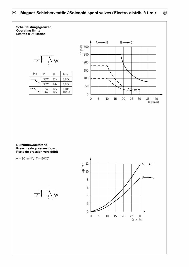
Schaltleistungsgrenzen
Operating limits
Limites d’utilisation
Durchflußwiderstand
Pressure drop versus flow
Perte de pression vers débit
ν = 30 mm2/s T = 50 °C

Magnet-Schieberventile / Solenoid spool valves / Electro-distrib. à tiroir 23æ
Schaltleistungsgrenzen
Operating limits
Limites d’utilisation
Gleichzeitige Durchströmung in zwei RichtungenSimultaneous bidirectional flowEcoulement simultané dans les deux sens
Durchströmung nur in einer Richtung, Pumpe an BFlow in a single direction, pump at BEcoulement dans un seul sens, pompe à B
Durchflußwiderstand
Pressure drop versus flow
Perte de pression vers débit
ν = 30 mm2/s T = 50 °C
·

24 Magnet-Schieberventile / Solenoid spool valves / Electro-distrib. à tiroir æ
Abmessungen
Dimensions
Cotes d’encombrement
Ausführung DIN/Version JET ISOVersion
« 0 521 000 001 12 V« 0 521 000 006 24 V
« 0 521 000 015 24 V P« 0 521 000 007 24 V « 0 521 000 002 24 V
« 0 521 000 005 12 V
**) Magnetspule: künftige Ausführung / Solenoid coil: Future design / Bobine: Version future**) Magnetspule: bisherige Ausführung / Solenoid: Present design / Bobine: Ancienne version

Magnet-Schieberventile / Solenoid spool valves / Electro-distrib. à tiroir 25æ
Aufnahmebohrung
Mounting dimensions
Cotes d’implantation

26 Magnet-Schieberventile / Solenoid spool valves / Electro-distrib. à tiroir æ
Magnetspule *) Solenoid coil *)Bobine *)
Magnetspule **) Solenoid coil **)Bobine **)
Abmessungen
Dimensions
Cotes d’encombrement
Ausführung DIN/Version JET ISOVersion
« 0 521 000 107 12 V « 0 521 000 109 24 V « 0 521 000 102 24 V« 0 521 000 108 12 V « 0 521 000 111 12 V « 0 521 000 106 12 V« 0 521 000 112 12 V
**) künftige Ausführung / Future design / Version future**) bisherige Ausführung / Present design / Ancienne version

Magnet-Schieberventile / Solenoid spool valves / Electro-distrib. à tiroir 27æ
Aufnahmebohrung
Mounting dimensions
Cotes d’implantation

28 Magnet-Schieberventile / Solenoid spool valves / Electro-distrib. à tiroir æ
Magnetspule *) Solenoid coil *)Bobine *)
Magnetspule **) Solenoid coil **)Bobine **)
Abmessungen
Dimensions
Cotes d’encombrement
Ausführung DIN/Version JET ISOVersion
« 0 521 000 210 12 V « 0 521 000 204 24 V « 0 521 000 200 24 V« 0 521 000 212 24 V « 0 521 000 209 12 V « 0 521 000 206 24 V P
« 0 521 000 207 12 V P« 0 521 000 213 24 V
**) künftige Ausführung / Future design / Version future**) bisherige Ausführung / Present design / Ancienne version

Magnet-Schieberventile / Solenoid spool valves / Electro-distrib. à tiroir 29æ
Aufnahmebohrung
Mounting dimensions
Cotes d’implantation

30 Magnet-Schieberventile / Solenoid spool valves / Electro-distrib. à tiroir æ
Anschlußblöcke Mounting blocks Blocs de montage
für Leistungseinbau for pipe mounting à raccordement direct
« 1 525 100 352
« 1 525 100 353
« 1 525 100 354

Robert Bosch GmbH
Geschäftsbereich
Automationstechnik
Industrielle Steuerungselektronik
Postfach 1162
D-64701 Erbach
Telefax (06062) 78-428
Robert Bosch GmbH
Geschäftsbereich
Automationstechnik
Pneumatik
Postfach 300240
D-70442 Stuttgart
Telefax (0711) 811-8917
Robert Bosch GmbH
Geschäftsbereich
Automationstechnik
Fahrzeughydraulik
Postfach 300240
D-70442 Stuttgart
Telefax (0711) 811-1798
Robert Bosch GmbH
Geschäftsbereich
Automationstechnik
Industriehydraulik
Postfach 300240
D-70442 Stuttgart
Telefax (0711) 811-1857
Robert Bosch GmbH
Geschäftsbereich
Automationstechnik
Baueinheiten Montagetechnik
Postfach 300207
D-70442 Stuttgart
Telefax (0711) 811-7712
Robert Bosch GmbH
Geschäftsbereich
Automationstechnik
Fahrzeughydraulik
Postfach 300240
D-70442 Stuttgart
Ihr Vertragshändler E Your concessionary EE Votre concessionnaire:
198776 1103 · AT/VHF · AKY 011/3 De/En/Fr (1.97) · Printed in Germany · Imprimé en Allemagne · 233
Technische Änderungen vorbehaltenE We reserve the right to make technical alterationsEE Sous réserve de modifications techniques