maico observations / modifications - n. moreland...
TRANSCRIPT
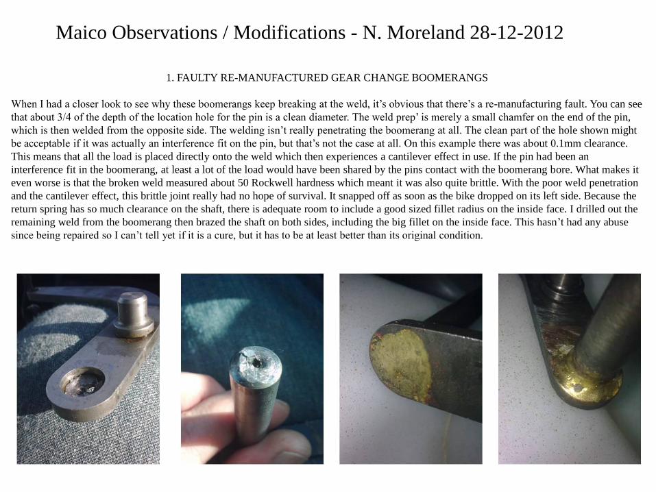
1. FAULTY RE-MANUFACTURED GEAR CHANGE BOOMERANGS
When I had a closer look to see why these boomerangs keep breaking at the weld, it’s obvious that there’s a re-manufacturing fault. You can see
that about 3/4 of the depth of the location hole for the pin is a clean diameter. The weld prep’ is merely a small chamfer on the end of the pin,
which is then welded from the opposite side. The welding isn’t really penetrating the boomerang at all. The clean part of the hole shown might
be acceptable if it was actually an interference fit on the pin, but that’s not the case at all. On this example there was about 0.1mm clearance.
This means that all the load is placed directly onto the weld which then experiences a cantilever effect in use. If the pin had been an
interference fit in the boomerang, at least a lot of the load would have been shared by the pins contact with the boomerang bore. What makes it
even worse is that the broken weld measured about 50 Rockwell hardness which meant it was also quite brittle. With the poor weld penetration
and the cantilever effect, this brittle joint really had no hope of survival. It snapped off as soon as the bike dropped on its left side. Because the
return spring has so much clearance on the shaft, there is adequate room to include a good sized fillet radius on the inside face. I drilled out the
remaining weld from the boomerang then brazed the shaft on both sides, including the big fillet on the inside face. This hasn’t had any abuse
since being repaired so I can’t tell yet if it is a cure, but it has to be at least better than its original condition.
Maico Observations / Modifications - N. Moreland 28-12-2012

2. NOTCHY AND STICKING GEARCHANGING
When I disassembled the 250 Maico engine that I had just bought, the only evidence I could see which pointed to a gear changing
problem, was the wear marks on the selector pinion. Initially I couldn’t see any reason why it should be worn like this, but when I
checked the Maico parts list, the washer which shims this pinion with respect to the crankcase floor, was listed as having a Ø10.5mm
hole. I measured mine as Ø10mm. On closer inspection of the selector pinion, it has a small fillet radius where the pinion pivot meets the
shoulder on the pinion gear. With the Ø10mm washer fitted over this pinion, it was forcing the pinion a further 0.5mm against the gear
selector plate, since the washer wasn’t seating on the pinion gear face at all, but on the fillet radius. Making a new washer with a
Ø10.5mm hole cured this sticking gearshift problem.
Gear selector plate
Ø10.5mm I.D. shim
Pinion and rivet wear
Pinion fillet fouling shim I.D.

3. NEAR ENGINE SEIZURE DUE TO FAULTY FUEL TAP
I bought a 1978 250cc Maico knowing it needed an engine overhaul. Once I had finished the engine rebuild and had run it in, I started for
the first time, since I bought it, to give it full throttle. I was testing it in an open field, so it really was a case of holding the throttle full
open for quite a few seconds. I noticed, half way across the field, that the engine felt like it was about to seize. Spitting on the cylinder
head and hearing it sizzling was a good test to prove how hot it was running. I backed of the ignition timing slightly, but it still wanted to
seize. The main jet that came in the bike was a 310, so I fitted a larger main jet, a 350, but it still wanted to seize. I fitted a still larger
main jet, a 440, but now, before it got a chance to reach the point of detonation, it ran out of petrol for a second or two. I coasted for a
few metres, then opened the throttle and the engine began to drive again, then ran out again. I then realised that the fuel delivery from the
petrol tank couldn’t supply the demand of the 440 main jet, quickly enough. With the smaller main jets used during the earlier tests, this
was also true, but because the 440 main jet was using the fuel up even quicker, it actually emptied the float bowl before I got from one
side of the field to the other and thereby emphasised the problem.
I then measured the flow from the fuel tap. It flowed 190cc per minute !!! Since Mikuni hexagon head jets are rated in flow per minute in
cc’s, the flow through my tap wasn’t even capable of supplying half the fuel that a 440 main jet requires at full flow, i.e. 440cc.
I removed the fuel tap completely, fitted a straight hose from the tank to the carb’ and that was it cured instantly. I was then able to reset
the timing, and reduce the jetting back to a 340 main.
I tested my 400cc Maico’s fuel tap out of curiosity and it flowed 1600cc minute, enough for over four 250cc engines!
What’s worth noting is, that at a short twisty track were there’s lots of braking, the problem would probably never have been noticed,
since there wouldn’t be any long periods of full throttle to empty the bowl, plus the bowl would be filling while braking. Then at the next
fast track, the engine would have seized for no apparent reason. Then after repair, it could appear fine for the next few races, (if they
happened to be at short twisty tracks), then again at the next fast track, it could seize again. With this problem you could find yourself
baffled why it seems good for a while, then seizes next time out, and so on.
When I tried to find a replacement tap, I was surprised how few even mention flow rate. I did find a few that would have done the job
regarding flow rate, but they didn’t suit for some other reason, such as plastic outlet ferrules, the wrong tap outlet angle, the wrong fitting
thread size, or the wrong price! I found a Hi-Level inline tap that would flow 1000cc per minute, but it couldn’t be fitted directly to the
bike. I made a body from aluminium that could be connected directly to a standard Maico tank fitting, while using the internals from
this Hi-Level tap.
The 1000cc per minute tap will supply more than enough for the 340 main jet. This will provide plenty of headroom rather than run a tap
which can just about manage to supply the demand.

This is the culprit. Don’t be
fooled that the size of the
hole in the outlet tube is
governing the flow rate. The
ducts going through the
rubber valve inside are
actually smaller than the
outlet bore, so they are the
most restrictive part. These
are selling on eBay as a
Maico fuel tap!
This tap body was made to suit
the internals from a Hi-Level
8mm inline tap. The aluminium
threaded boss,
(M16 x 1 Left Hand Thread)
is connected to the main body
by using an HTS2000 alloy, or
similar, and a simple propane
torch with a pinpoint nozzle.
SCRAP!!!!!!
(unless you race on the pilot jet)
190cc / minute 1000cc / minute
The only suitable taps I
could find where they
were quoting a good flow
rate were about $100
dollars each. I needed one
plus a spare, so I decided
to go for the Hi Level
option and mill the bodies
from billet. You can buy
these Hi Level taps for
about £8.
Here are the internals
from the Hi Level tap.
Rather than dump the
main body from the tap, if
you clean off the paint and
saw it up into pellets, you
can use these as the filler
to connect the aluminium
threaded boss to the billet
body, by using a propane
torch and the same
technique as you would
for Lumiweld, HTS2000
or similar.


4. HOW TO BUMP A MAICO ON YOUR OWN WITHOUT MAICO HILL
As anyone who owns a Maico knows, sooner or later you’re going to be giving it a bump start to coax it into life. If Maico Hill isn’t available
it really can be quite difficult to get it started on your own, or even with a couple of willing volunteers, once it drags the back wheel on wet
ground. Pushing a bike with a dragging clutch, while operating the decompressor, the throttle and gear lever all in harmony can be
challenging, but now hears the answer! It’s worked for me on numerous occasions when I hadn’t the energy to kickstart it after falling off..
Simply get the piston into the position you normally would, supposing you were about to kickstart it. i.e. just slightly past TDC. Then select
4th gear, but then nudge the lever down a tiny bit, so that it is in a false neutral between 4th and 3rd. If you even have a slight incline, then
push like mad, jump on board, pull in the decompressor, whack the gear lever down into third without putting your hand near the clutch.
Keep the decompressor in until it comes alive then you’re in business. Obviously this works for a Maico that has no reason not to start. If you
have a real dog, then you’ve no chance. A box of Sunny Jim’s is the only answer to getting one of those fired up.
5. MAICO GEARBOX SPROCKET BEARING SEALS
When I rebuilt my 250 engine, replacing all the gearbox bearings and seals, I noticed that the old gearbox output shaft bearing had its inner
seal removed. I automatically pulled off the seal from the replacement bearing, assuming that the gearbox oil was being relied upon to
lubricate this bearing from the inside. Wrong! Once I had the engine fitted and I began to fine tune the Maico clutch, (as you do), I leaned the
bike down on its right side to remove the clutch casing. Next thing I knew all the gearbox oil was over the floor. When I went back to the
manual, it indicates that the bearing is in fact a 6206 2RS, i.e. 2 x Rubber Seals. I asked H. McQuaid about this, and he said a brand new
Maico crankcase he bought, complete with bearings, came with the bearing seals fitted to both sides of the output shaft bearing.
6. MAICO WHEEL BEARING SEALS
While on the subject of bearing seals, on some Maico wheels the inner rubber seals on the 2RS bearings actually do need to be removed. If the
wheels are fitted with the type of spacing bush which includes a small pocket in each end of the spacer to help locate the bearings centrally,
then the seal needs removed. If you don’t remove these inboard seals the rubber just constantly rubs on the spacing bush generating heat. This
is even described in the Maico Haynes manual, but just for those with the pocketed spacer bushes.
7. MAICO FRONT WHEEL NOISES
Many Maicos make a strange noise when the front wheel is spun around when on the stand. This is caused by after market brake shoes which
are supplied with about Ø10mm brake shoe springs. The originals were about Ø7mm, which barely cleared the casting webs within the
wheel hub. However, when Ø10mm springs are fitted, they constantly rub on these casting webs.
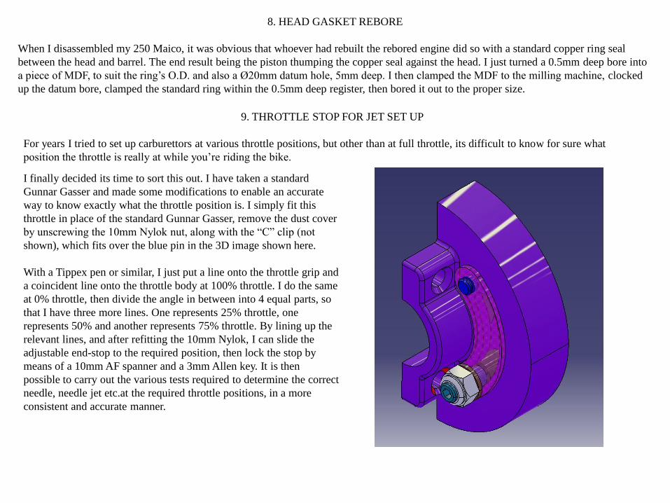
9. THROTTLE STOP FOR JET SET UP
For years I tried to set up carburettors at various throttle positions, but other than at full throttle, its difficult to know for sure what
position the throttle is really at while you’re riding the bike.
I finally decided its time to sort this out. I have taken a standard
Gunnar Gasser and made some modifications to enable an accurate
way to know exactly what the throttle position is. I simply fit this
throttle in place of the standard Gunnar Gasser, remove the dust cover
by unscrewing the 10mm Nylok nut, along with the “C” clip (not
shown), which fits over the blue pin in the 3D image shown here.
With a Tippex pen or similar, I just put a line onto the throttle grip and
a coincident line onto the throttle body at 100% throttle. I do the same
at 0% throttle, then divide the angle in between into 4 equal parts, so
that I have three more lines. One represents 25% throttle, one
represents 50% and another represents 75% throttle. By lining up the
relevant lines, and after refitting the 10mm Nylok, I can slide the
adjustable end-stop to the required position, then lock the stop by
means of a 10mm AF spanner and a 3mm Allen key. It is then
possible to carry out the various tests required to determine the correct
needle, needle jet etc.at the required throttle positions, in a more
consistent and accurate manner.
8. HEAD GASKET REBORE
When I disassembled my 250 Maico, it was obvious that whoever had rebuilt the rebored engine did so with a standard copper ring seal
between the head and barrel. The end result being the piston thumping the copper seal against the head. I just turned a 0.5mm deep bore into
a piece of MDF, to suit the ring’s O.D. and also a Ø20mm datum hole, 5mm deep. I then clamped the MDF to the milling machine, clocked
up the datum bore, clamped the standard ring within the 0.5mm deep register, then bored it out to the proper size.
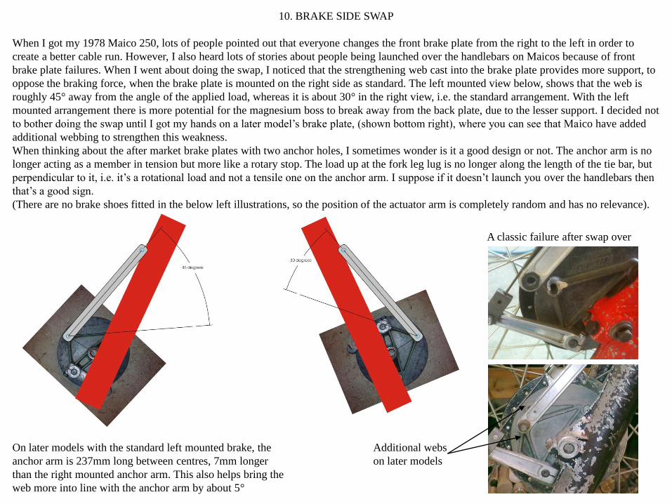
Additional webs
on later models
On later models with the standard left mounted brake, the
anchor arm is 237mm long between centres, 7mm longer
than the right mounted anchor arm. This also helps bring the
web more into line with the anchor arm by about 5°
10. BRAKE SIDE SWAP
When I got my 1978 Maico 250, lots of people pointed out that everyone changes the front brake plate from the right to the left in order to
create a better cable run. However, I also heard lots of stories about people being launched over the handlebars on Maicos because of front
brake plate failures. When I went about doing the swap, I noticed that the strengthening web cast into the brake plate provides more support, to
oppose the braking force, when the brake plate is mounted on the right side as standard. The left mounted view below, shows that the web is
roughly 45° away from the angle of the applied load, whereas it is about 30° in the right view, i.e. the standard arrangement. With the left
mounted arrangement there is more potential for the magnesium boss to break away from the back plate, due to the lesser support. I decided not
to bother doing the swap until I got my hands on a later model’s brake plate, (shown bottom right), where you can see that Maico have added
additional webbing to strengthen this weakness.
When thinking about the after market brake plates with two anchor holes, I sometimes wonder is it a good design or not. The anchor arm is no
longer acting as a member in tension but more like a rotary stop. The load up at the fork leg lug is no longer along the length of the tie bar, but
perpendicular to it, i.e. it’s a rotational load and not a tensile one on the anchor arm. I suppose if it doesn’t launch you over the handlebars then
that’s a good sign.
(There are no brake shoes fitted in the below left illustrations, so the position of the actuator arm is completely random and has no relevance).
A classic failure after swap over

11. THE INFAMOUS MAICO CLUTCH
Because of the Maico clutch infamy, I’m not even going to try to give a complete explanation of what I understand about how this works. I
don’t believe I have enough communication skills to achieve that! Instead I will list just a few findings that might help someone else as they
aim to get their clutch to work even half decently. Believe it or not, I think if a few basic things are inspected and corrected, it really isn’t so
complicated after all. Because the whole operation of the clutch is so marginal, there are a some tolerances which can’t really be overlooked,
tolerances which a normal clutch arrangement might more easily accommodate. The abnormality of the Maico clutch all stems from its speed
ratio with respect to crankshaft RPM. Since the ratio is quite low, it means that the clutch is revving pretty quick compared to most other
motocross clutches. Because its revving harder, it doesn’t encounter so much torque, hence the clutch diameter is pretty small and the gearbox
components pretty lightweight. However one problem with this small primary drive ratio is that any deviation from the ideal is magnified
accordingly. This leads to the following points:
a). If the steel plates are warped at all, dump them. If you don’t then all your clutch spring force is consumed by trying to flatten your warped
plates. By the time it has the warped plates flattened, there is virtually no spring force left to actually compress the steel and sintered plates
together. The result is a clutch that will drag badly, making it difficult to select gear without the bike wanting to run off. It will also make the
bike difficult to get out of gear once a gear has been engaged. And on top of all that the clutch will probably slip too.
b). Beware that if you buy a new set of steel plates that they might well be thinner than the originals. I have seen older steel plates measuring
about 1.15mm and brand new ones measuring 1.0mm. Over all six plates, that adds up to a 0.9mm reduction in stack height. This reduction in
stack height has a similar affect as having badly worn sintered plates, since this obviously reduces spring pre-load on the clutch plate stack
considerably, inevitably leading to clutch slip. Theoretically you would really need to accommodate this stack height reduction by adding a
0.9mm shim below the spring pack, but in reality adding another 1.0mm thick spring is probably a more practical solution. There are other
complications to the height change however. See point d). below.
c). The main clutch drum which the first installed sintered plate makes contact with, can wear to such an
extent that the shoulder which the plate fits over, can actually stick up even higher than the uppermost face of
the sintered plate. If the sintered plate nominal dimension is 3mm, a 2.5mm step height should be fine, but I
have seen hubs so badly worn that the step height is greater than 3mm. This means that the first steel plate to
be inserted after the first sintered plate, doesn’t actually contact the sintered plate at all but clamps directly
onto the clutch drum step. Obviously this provides no drive at all. Also, the face of this step usually has some
spot weld lumps on it, so that isn’t very friendly to the steel plates if they are being clamped against these
lumps by the clutch spring pre-load pressure. You can easily destroy a good steel plate by overlooking this.
I skim this step face until it is 0.5mm lower than the first sintered plate installed.
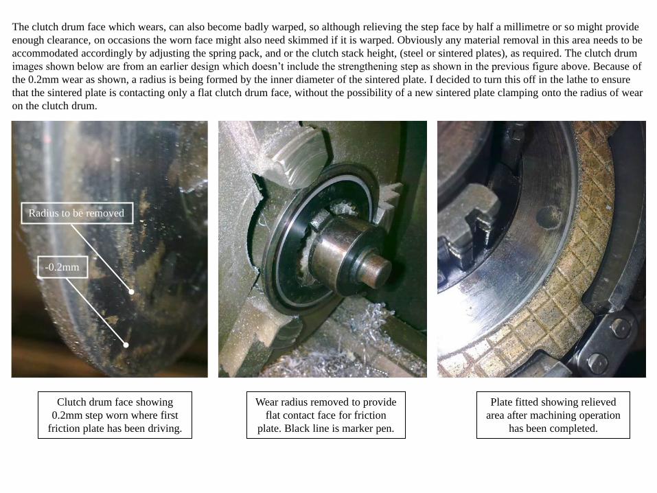
Clutch drum face showing
0.2mm step worn where first
friction plate has been driving.
-0.2mm
Wear radius removed to provide
flat contact face for friction
plate. Black line is marker pen.
Plate fitted showing relieved
area after machining operation
has been completed.
The clutch drum face which wears, can also become badly warped, so although relieving the step face by half a millimetre or so might provide
enough clearance, on occasions the worn face might also need skimmed if it is warped. Obviously any material removal in this area needs to be
accommodated accordingly by adjusting the spring pack, and or the clutch stack height, (steel or sintered plates), as required. The clutch drum
images shown below are from an earlier design which doesn’t include the strengthening step as shown in the previous figure above. Because of
the 0.2mm wear as shown, a radius is being formed by the inner diameter of the sintered plate. I decided to turn this off in the lathe to ensure
that the sintered plate is contacting only a flat clutch drum face, without the possibility of a new sintered plate clamping onto the radius of wear
on the clutch drum.
Radius to be removed

d). As the stack height reduces due to plate wear, (either sintered or steel), or by replacing 1.15mm steel plates with 1.0mm plates, inevitably
the thrust button is going to move out in the direction of the clutch casing, i.e. towards the arm which actually pushes the button. Since the
relationship between the actuator arm and the clutch button has such an influential effect on clutch operation, it is good to keep an eye on this
relationship. Since the actuator arm acts like a cam, the button to cam clearance is very important. If this clearance is much too big, then the
clutch action is pretty useless. Because the cam has to turn so far in order to take up any clearance, the amount of linear action along the
mainshaft axis is really small, because the contact point is now so far away from the position of maximum action. Think of a bicycle pedal at
12 o’clock as opposed to 3 o’clock. At 12 o’clock a 5° rotation will give a vertical pedal displacement of 0.76mm, (i.e. when a 200mm crank
arm is fitted). But at 3 o’clock a 5° rotation, (on the same crank length), provides a vertical displacement of 17.4mm.
To achieve the ultimate action, the button to actuator arm clearance should be scrutinised regularly as clutch plate stack height decreases.
Maico quote 0.55mm-0.95mm Failure to keep an eye on this could lead to a no clearance situation when the clutch will begin to slip due to a
constant button to arm contact. I would say this is a vital detail to be concerned with if you wish to have a really good clutch on a Maico.
As clutch wear takes
place, this button,
along with the whole
clutch stack assembly,
moves in direction of
arrow.
Shimmed button
design not shown.
With too much clearance,
clutch action is minimal, hence
lever rotation gives very little
clutch button displacement
With shimmed button clearance,
clutch action is maximised.
These shimmed button designs seem
to be very scarce, but they are
referred to in Maico service bulletins.
(See above left).

63.5mm 63.5mm
9.85mm
Spindle O.D. to
spindle flat = 9.85mm
Clutch casing face to
spindle O.D. = 54.3mm
Therefore, clutch casing face to
spindle flat =
54.3mm+9.85mm=64.15mm
This 64.15mm should be constant on
all similar model Maico casings..
On the other hand, the 63.5mm
dimension will be machine specific,
and will increase as clutch plates
wear. This can lead to a no clearance
condition between the button and the
flat on the actuator.
Measuring my crankcase face to
button end = 63.5mm
Gasket = 0.6mm
Button to spindle flat clearance =
64.15mm+0.6mm-63.5mm=1.25mm
54.3mm
This 1.25mm is too much.
Maico quote 0.55mm to 0.95mm.
My button needs to be 0.5mm taller.
The yellow line shown left, is parallel
to the casing mating face. The white
line shows the spindle flat in the
position it was when the casing was
removed, the flat having been up hard
against the button before removal, i.e.
the spindle already rotated by 10°
Too much spindle pre-rotation leads
to lesser clutch displacement, hence a
clutch that will always drag.

e). The spring stack height will obviously have a crucial affect on the clutch behaviour. I believe this can be fine tuned only after all of the
above points have been addressed. Trying to get just the right spring pack will be virtually impossible until these other more fundamental
features have first been sorted out.
f). Clutch baskets can become very worn where the sintered clutch plate tongues make contact. The only way to overcome this is to file
the basket contact faces flat again. Its important to file them reasonably uniformly lest the full engine torque ends up being transmitted
through a single or just a few tongues. Theoretically the load should be shared uniformly by all tongues.
These faces can become very
badly stepped

g). Many clutch baskets which have had a hard life, generally have a kickstart ratchet gear ring which is knackered. You can normally see that
the sharp edge from the dovetailing angle has gone and if this is so it’s time for a new gear. The new gear will need riveted on using rivets as
dimensioned in a previous note. If you are unfortunate enough to have one of the kickstart gears that someone has welded on, then buying and
fitting a new gear isn’t going to be so easy. If it was me I would just go buy a brand new / old stock clutch basket. The kickstart gear itself and
the riveting operation would be costly enough both in time and effort, whereas for just a few pounds extra you can buy a brand new / old stock
basket, complete with the kickstart gear factory riveted in place. Once I see welding on such a stressed component I immediately abandon ship
since there is absolutely no way of knowing what influence the welding operation has had on the material properties, plus it makes the thing
more or less unserviceable without the use of an angle grinder. It just becomes a real bodged job.
Once these edges get
rounded, the kickstart
becomes more or less
useless, even more so
on a 400cc or 440cc

People have asked me why I write:
“DON’T USE KICKSTART”
on my petrol tank.
Well, here’s what happened the last
time someone with no Maico
kickstart knowledge tried to start this
bike.
12. A FEW ODD PHOTOS
I just started using HTS 2000 rods
for aluminium repairs, e.g. petrol
tank boss. It just acts like an
aluminium solder, so it means that
repairs can be done without worrying
about melting the aluminium. Things
which I would have binned before
are now easily repaired. It is as
strong as the demonstrations show.
Checkout videos at:
www.aluminiumrods.co.uk
I discovered that some zinc alloys
can be used just like the HTS 2000,
so experimenting with some pieces
of scrap could save you quite a bit of
money, when you consider the cost
of HTS 2000 rods.
LEFT- a flat clutch plate showing a
uniform wear pattern.
RIGHT-A warped plate showing a
non-uniform wear pattern.