main coolant pump shaft seal guidelines
TRANSCRIPT

Main Coolant Pump Shaft Seal Guidelines Volume 2: Operational Guidelines Keywords:
Pump Seals Operation Reactor Coolant Pumps Seal Reliability DO NOT MICROFILM
COVER
Prepared by Borg-Warner Corporation Carson, California
E L E C T R I C P O W E R R E S E A R C H I N S T I T U T E
DISCLAIMER
This report was prepared as an account of work sponsored by an agency of the United States Government. Neither the United States Government nor any agency Thereof, nor any of their employees, makes any warranty, express or implied, or assumes any legal liability or responsibility for the accuracy, completeness, or usefulness of any information, apparatus, product, or process disclosed, or represents that its use would not infringe privately owned rights. Reference herein to any specific commercial product, process, or service by trade name, trademark, manufacturer, or otherwise does not necessarily constitute or imply its endorsement, recommendation, or favoring by the United States Government or any agency thereof. The views and opinions of authors expressed herein do not necessarily state or reflect those of the United States Government or any agency thereof.

DISCLAIMER Portions of this document may be illegible in electronic image products. Images are produced from the best available original document.

EPRI"OP~2965-¥ol.2
DE83 902279
Main-Coolant-Pump Shaft-Seal Guidelines. Volume 2. Operational Guidelines.,
NP-2965, Volume 2 Research Project 1556-1
Final Report, March 1983
Prepared by
BORG-WARNER CORPORATION Byron Jackson Pump Division
Energy Systems Development Center 17929 Adria Maru Lane
Carson, California 90746
Principal Investigators C. E. Fair
A. 0. Greer
l iT i iE ' PtlTiSiS SF THIS iEPiiT iJE IlLEilSlE? it has bees reprsiassS frsm t&e test availafele eopf te permit the broadest pessple afailabiiitf.
Prepared for
Electric Power Research Institute 3412 Hillview Avenue
Palo Alto, California 94304
EPRI Project Manager F. E. Gelhaus
System Performance Program Nuclear Power Division
% < ^
WiaiaUTfQM 6F THIS C-BfilSfll IS yfUllTES

ORDERING INFORMATION
Requests for copies of this report should be directed to Research Reports Center (RRG), Box 50490, Palo Alto, CA 94303, (415) 965-4081. There is no charge for reports requested by EPRI member utilities and affiliates, U.S. utility associations, U.S. government agencies (federal, state, and local), media, and foreign organizations with which EPRI has an information exchange agreement. On request, RRG will send a catalog of EPRI reports.
NOTICE This report was prepared Py the organization(s) named below as an account of work sponsored by the Electric Power Research Institute Inc (EPRI) Neither EPRI, members of EPRI, the organization(s) named below, nor any person acting on behalf of any of them (a) makes any warranty, express or implied, with respect to the use of any information, apparatus method, or process disclosed in this report or that such use may not infringe private ly owned rights or (b) assumes any liabilities with respect to the use of, or for damages resulting from the use of, any information, apparatus method or process disclosed in this report
Prepared by Borg-Warner Corporation Carson, California

EPRI PERSPECTIVE
PROJECT DESCRIPTION
This project (RP1556-1) was undertaken as a logical extension of earlier EPRI work
to investigate the causes of failure and the state of the art in the design of
nuclear main coolant pumps (MCPs). Both the failure history study reported in EPRI
Final Report NP-1194 and the design study reported in EPRI Final Report NP-2458
concluded that problems with the mechanical face seal were major contributors to
pump unavailability and to plant unavailability.
A project survey to update and augment this earlier work (reported in EPRI Interim
Report NP-2611, Volumes 1 and 2) substantiated that a wide spectrum of reliability
has been experienced in operating and maintaining "identical" shaft seal systems.
The field survey responses were grouped into three general failure-cause categor
ies: system-induced, maintenance-induced, and design-related. For each category,
fault trees were constructed to describe how seven or eight events typically lead to
the observed failure modes. This data analysis did not reveal a predominant event-
failure mode relationship but rather pointed out that corrective actions in each of
the three categories are necessary to improve seal and seal auKiliary-system reli
ability. These findings provided the bases for completing a comprehensive analysis
of seal reliability and for developing guidelines with specific recommendations that
would lead to improved MCP availability.
PROJECT OBJECTIVE
The overall goal was to develop a composite set of technical guidelines that can be
used interactively by the utility, the nuclear steam systems supplier, the architect-
engineer, and the pump manufacturer to increase the reliability of both the seal and
seal auxiliary systems while at the same time to improve pump performance.
ill

PROJECT RESULTS
This document is one part of the three-volume set of guidelines that has been
developed to present the composite of required corrective actions. The volume
titles ares
* Volume 1; Maintenance Manual Guidelines
* Volume 2; Operational Guidelines
* Volume 3; Specifications Guidelines
Woven through the specific details of each of these recommendations, a common
problem-cause thread is apparent: the lack of an effective communication-response
cycle between the pump seal supplier, the system designer, and the operational
user. The data indicate that each of these parties has a contribution to add to the
total corrective action. History indicates that successful mitigation of seal
failure will only come about if these contributions are responded to in a spirit of
mutual cooperation.
These guidelines are of interest to pump seal suppliers, system designers, and
utility operations and maintenance staffs.
Floyd E. Gelhaus, Project Manager Nuclear Power Division
iv

ABSTRACT
This report presents a set of guidelines and criteria for improving main coolant
pump shaft seal operational reliability. The noted guidelines are developed
from EPRI sponsored nuclear power plant seal operating experience studies.
Usage procedures/practices and operational environment influence on seal life
and reliability from the most recent such survey are summarized. The shaft seal
and its auxiliary supporting systems are discussed both from technical and
operational related viewpoints.
V


ACKNOWLEDGMENTS
The preparers of this report wish to thank the following persons for the contribu
tions made in the areas of mechanical shaft seal design, field experience and
pump/seal/system interfacing. They are: Messrs. C. Boster and W. Hickey for
their ptimp and system knowledge, Mr. W. Wiese for his seal design and extensive
testing experience, and Mr. J. Marsi for his overall technical guidance.
vii

Section
TABLE OF CONTENTS
Page
1.0 INTRODUCTION
2.0 DESCRIPTION OF MECHANICAL SHAFT SEALS AND SEAL INTERFACES
4 . 0
5 , 0
6 . 0
3 . 1
3 . 2
3 . 3
3 . 4
3
2.1 Mechanical Seal Description 5
2.2 Hydrodynamic Seals 6
2.3 Hydrostatic Seals 9
2.4 Pump Shaft - Seal Interface 11
3.0 SEAL AUXILIARY SYSTEMS 15
Excessive Control Bleedoff Flow 24
Loss of Component Cooling Water 25
Contaminated Seal Supply Water 28
Venting Procedures 30
INSTRUMENTATION 32
PERSONNEL ERRORS 37
THE FAULT TREE ASSOCIATED WITH SEAL OPERATIONAL
ENVIRONMENT 41
7.0 GUIDELINES FOR PROVIDING GOOD SHAFT SEAL
OPERATING CONDITIONS 44
7.1 Inadequate Lubricating Film 44
7.2 Vapor Seal Supply Tank Level 49
7.3 Loss of Seal Cooling 49
7.4 Seal Water Cleanliness 51
7.5 Instrumentation and Control 51
7.6 Human Error 53
7.7 Failure Reporting - Documentation 55
8.0 REFERENCES 56
IX


LIST OF FIGURES
Page
Schematic Presentation of a Typical Main Coolant Pump ^
Hydrodynamic Seal Stage Types 7
A Typical 3 Stage Hydrodynamic Seal Arrangement (With a 4th Vapor Stage) 8
Typical Hydrostatic Seal Stage 10
A 3-Stage Hybrid-Hydrostatic Seal Arrangement 12
Hydrodynamic Seal Auxiliary System 17
A Hybrid-Hydrostatic Seal Auxiliary System 18
Thermal and Hydraulic Elastic Ring
Distortion 20
Cause of Instrumentation and Control Failures 34
Reported Causes of I S C Failures 35
Categorization of 57 Personnel-Related Operator Errors Identified by One Utility (Troiible Memos) 39
Operational Related Seal Failure Mechanism 43

SUMMARY
An investigation into main coolant pump (MCP) shaft seal failures in U.S. commercial
nuclear power generating stations has been completed. The purpose of this project
was to define the means to reduce high-cost, lost-power outages caused by MCP shaft
seal failures. The initial effort consisted of a survey of U.S. commercial nuclear
plants and led to the grouping of the observed failure modes into system/operational-
related, maintenance-related, or design-related categories. A report (EPRI Interim
Report NP-2611, Volumes 1 and 2, Main Coolant Pump Shaft Seal Reliability Investiga
tion) , containing the results of this survey was published in September 1982. The
survey sample was representatively large (27% of total U.S. commercial plant popula
tion) and included the three Industry seal suppliers (Bingham-Willamette, Byron
Jackson, and Westinghouse Electric Corporation). Operationally incurred and/or
induced problems and seal redesign parameters were identified. Failure hypotheses
in the form of fault trees were developed to describe the failure mechanisms, and
recommendations were made for seal reliability improvement.
The results of the survey reaffirm that the primary coolant pump shaft seals are
complex and sophisticated devices. As a critical pressure-boundary component in the
primary heat transport loop, the seal system is often taxed beyond design limits and
forced into a failure mode. Experience shows that the seals have often been sub
jected to stress conditions exceeding their design capability because of improper
operator procedures. In other instances, the overstresses were caused by seal
auxiliary-system malfunctions or inadequacies. Problems during maintenance have
been aggravated by a lack of appreciation of the component's sophistication and
delicacy, and the findings show the severity and frequency of the "built-in" fail
ures resulting from improper maintenance. Included, and synergistically interwoven
amongst these field-induced problems, are the failures due to design shortcomings.
These problems relate to the inherent parameters that require either a redesign for
greater operating margins or alternate design mechanizations to improve the reli
ability of the shaft seal assembly.
From these results, user-oriented Maintenance Manual, Operational, and Specification
Guidelines were generated. Each of the three volumes is written as a stand-alone
s-1

document. However, the solution to the seal failure problem will only come from the
successful enactment of the recommendations in all three guidelines. These volumes
are;
1. Volume 1; Maintenance Manual Guidelines. This volume represents a set of guidelines and a listing of information and data that should be included in maintenance manuals and procedures for MCP shaft seals. The maintenance-oriented results from the project's operating experience study are summarized. The shaft seal and its auxiliary supporting systems are discussed from both technical and maintenance-related viewpoints.
2. Volume 2; Operational Guidelines. This volume presents a set of guidelines and criteria for improving MCP shaft seal operational reliability. The data relating to usage procedures and practices and operational environmental influence on seal life and reliability from the project survey are summarized. The shaft seal and its auxiliary supporting systems are discussed from both technical and operational-related viewpoints.
3. Volume 3; Specification Guidelines. This volume presents a set of guidelines and criteria to aid in the generation of procurement specifications for MCP shaft seals. These guidelines were developed from EPRl-sponsored nuclear power plant seal operating experience studies, from a review of pump and shaft seal literature, and from discussions with pump and seal designers.
The recommendations in these three volumes of seal guidelines, if diligently applied,
should enhance shaft seal procurement, operation, and maintenance, thus increasing
equipment and plant availability.
S-2

1.0 INTRODUCTION
Forced outages caused by Main Coolant Pump (MCP) shaft seal failures
can be partially attributed to either seal auxiliary system malfunctions
or operator-procedural incompatabilities. Responses from utilities
participating in the recent mechanical shaft seal operating experience
survey indicated a high correlation of seal problems to some system
anomaly or condition that often preceded seal failures. Numerous
responses identified or implied that improper operating procedures had
caused many catastrophic seal assembly failures. These survey results
are contained in Reference 1 from which the following operational
induced failure causes are extracted:
1. Water contamination such as abrasives, debris, "crud";
2. Pump transients such as trip or other emergency events;
3. Loss of injection flow;
4. Temperature and/or pressure transients;
5. Loss of cooling water and/or large temperature excursions;
6. Staging flow (controlled bleedoff) line closure/blockage;
7. Low pressure starts or excessive differential pressure
across seal; and
8. Improper venting.
Ninety percent of the surveyed power plants experienced a combination
of from two to six of these noted conditions.
A previous survey sponsored by EPRI (Reference 2) identified the
following operational causes of seal failures:
1. Dirt or foreign material in the seal system;
2. Improper venting;
3. Seal auxiliary system deficiencies;
4. Inadequate seal leakoff flow instrumentation; and
5. Improper pump and seal auxiliary system operation
(particularly under off-design conditons).
The two independent investigations indicate that a significant percent
age of mechanical seal related outages have been caused by operator/
procedural problems and/or seal auxiliary system deficiencies. System
1

deficiencies as used categorically here includes any problems resulting
from the inability of the seal support system to sustain seal life in
off-normal design operating conditions.
Another EPRI sponsored project investigated the impact of personnel
errors on power plant reliability (Reference 3) . This study estimates
that 15 to 30% of the system failures experienced by the 47 utilities
participating in the survey were directly caused by or involved some
level of personnel errors. The utilities stated that personnel errors
were most often operator errors but it was an±iiguous whether maintenance
errors were less common or less visible. The two seal performance
surveys (References 1 and 2) however indicate that both operator and
maintenance induced failures should be treated with equal consideration
insofar as mechanical shaft seals are concerned. The consensus of the
respondents to the personnel error survey felt that training and the
application of human factors principles to both procedure and equipment
design are among the most effective ways to improve personnel reliabil
ity.
The mechanical shaft seal operational guidelines and standards compiled
herein are heavily influenced by these previous survey results. The
guidelines reflect the importance of:
1. Human factors disciplines in power plant design and in
the development of operating procedures;
2. Rigourous operator procedural reviews and training
using training aids;
3. Application of system engineering procedures for identi
fying, specifying and controlling all interfaces;
4. Effective communication between pump/seal supplier,
system designer and operational user of the equipment;
5. Definition of all operating modes/conditions especially
all possible abnormal system/equipment operating condi
tions and detail specific method of recovery from same;
6. Improving the reliability of the seal auxilliary system
such that seal degradation is eliminated as a result of
single point system failure; and
7. Seal system instrumentation and trend tracking/analysis
of critical seal operating parameters.
2

In addressing the implementation of seal related guidelines and
standards, a major concern is applicability to the approximately 100
existing operating plants. Ideally, all modifications to procedure
and hardware should not force plant operating interruptions or should
be amendable to incorporation during scheduled outage periods. Since
this is not feasible for all recommended actions and since many of
the recommendations are already implemented in some generating plants,
the guidelines are identified and discussed in listed form from which
the user may select any combination based on his particular implementa
tion circumstance. Such selection will vary from facility to facility
as operating variables and trade-offs allow.
2.0 DESCRIPTION OF MECHANICAL SHAFT SEALS AND SEAL INTERFACES
Electric motor driven single stage vertical centrifugal pumps provide
the primary coolant circulation in U.S. commercial nuclear power
generating plants. The pump and motor shafts are rigidly coupled and
are rotationally guided by two oil lubricated motor bearings and one
pump water bearing (see Figure 1). Axial thrust loads are supported
by a thrust bearing in the motor assembly. Primary coolant sealing is
accomplished by a seal assembly (sometimes referred to as a cartridge)
fitted around the pump drive shaft.
The shaft seal is exposed to a demanding operational environment
through the following system interfaces:
1. Mechanically and hydraulically induced shaft translations/
vibrations (both vertical and horizontal) are transmitted
to the seal by the pump shaft and have a significant
effect on seal reliability.
2. Thermal coupling of the shaft seal with the primary
coolant system through direct contact with primary
coolant water and heat conduction through the pump
structure and shaft has a large influence on seal
reliability.
3. Reactor system water quality/cleanliness is a potential
seal reliability degrading factor.
4. The migration of system gas voids to an operating seal
cavity can result in the loss of the lubricating fluid
3

LEAKAGE FLOW
CONTROLLED BLEEDOFF
STAGING COILS
INJECTION WATER
C00LI^3 WATER 5
PRIMARY COOLANT
MOTOR JOURNAL AND THRUST BEARING
MOTOR
MOTOR JOURNAL BEARING
RIGID SPACER COUPLING
T~ AP-
AP-
APn
Pj_ = STAGING DIFFERENTIAL PRESSURE
PUMP MECHANICAL SHAFT SEAL CARTRIDGE (3 STAGE)
RICIRCULATION PUMP
PUMP BEARING
IMPELLER
FIGURE 1 SCHEMATIC PRESENTATION OF TYPICAL MAIN COOLANT PUMP
4
film and thus lead to seal failure.
5. System induced thermal/pressure transients; and
6. Auxiliary supply system induced thermal/pressure tran
sients.
An understanding of the interfaces and interrelationships of all pump
dynamic operating characteristics, reactor coolant thermal/fluid
transport properties, and seal auxiliary systems is essential for
identification and prevention of all seal failure forcing modes. Seal
operational integrity requires adequate flow, pressure, temperature
and shaft displacement instrumentation along with means to control
some of these parameters. Adherence to proper procedures for normal
and off-design conditions must be stringently practiced and critical
seal operating parameters must be tracked and analyzed.
Thus, to discuss MCP mechanical shaft seal operational guidelines and
standards, it is helpful to first describe shaft seal operating
principles, seal auxiliary systems, system instrumentation and pump/
primary coolant system characteristics which may affect seal perfor
mance.
2.1 Mechanical Seal Description
The following is a brief description of the hydrodynamic and hydrostatic
shaft seal concepts and design configurations which are predominate in
nuclear power generating MCP service. The methods presently used for
assembling and installing these mechanical shaft seals are:
1. The single cartridge method:
The assembly is made up as a self-contained package
including seal faces (rings), back-up rings, elastomers,
shaft sleeve, springs, pressure breakdown cells, and
other ancillary parts, all of which are preassembled
with a controlled static seal face loading. After
bench testing for hydraulic integrity, the cartridge is
installed over the pirnip shaft with the shaft sleeve
properly positioned and locked.
2. The limited shaft seal assembly arrangement:
The installation of this arrangement consists of some
5
preassembly of seal components with the balance assembled
at the p'ump site and over the pump shaft calling for
careful positioning of critical parts in a confining
space. This method requires extreme care and protection
against contamination.
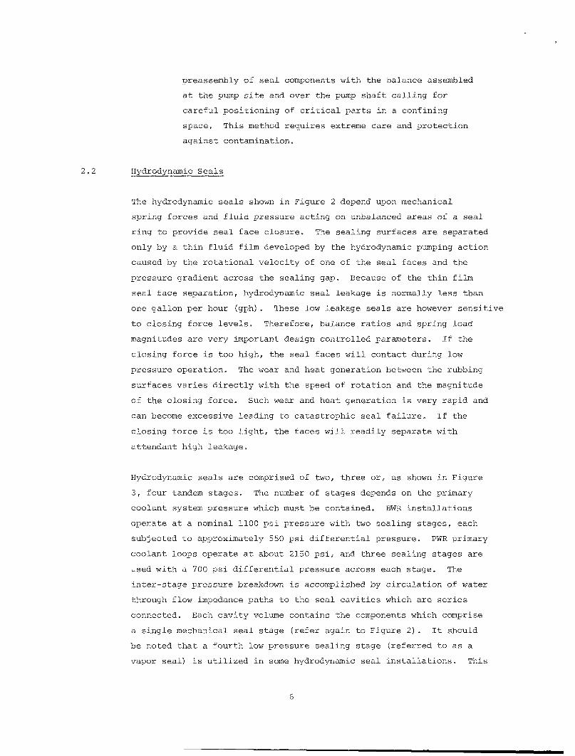
2,2 Hydrodynamic Seals
The hydrodynamic seals shown in Figure 2 depend upon mechanical
spring forces and fluid pressure acting on unbalanced areas of a seal
ring to provide seal face closure. The sealing surfaces are separated
only by a thin fluid film developed by the hydrodynamic pumping action
caused by the rotational velocity of one of the seal faces and the
pressure gradient across the sealing gap. Because of the thin film
seal face separation, hydrodynamic seal leakage is normally less than
one gallon per hour (gph). These low leakage seals are however sensitive
to closing force levels. Therefore, balance ratios and spring load
magnitudes are very important design controlled parameters. If the
closing force is too high, the seal faces will contact during low
pressure operation. The wear and heat generation between the rubbing
surfaces varies directly with the speed of rotation and the magnitude
of the closing force. Such wear and heat generation is very rapid and
can become excessive leading to catastrophic seal failure. If the
closing force is too light, the faces will readily separate with
attendant high leakage.
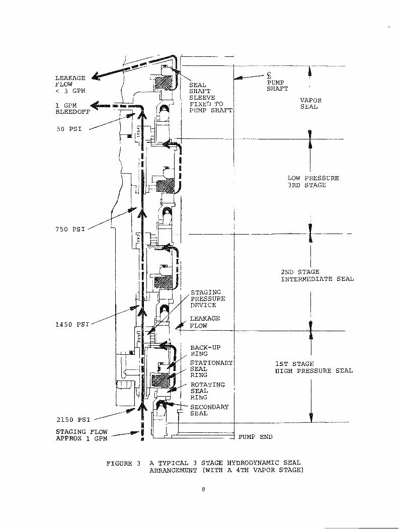
Hydrodynamic seals are comprised of two, three or, as shown in Figure
3, four tandem stages. The number of stages depends on the primary
coolant system pressure which must be contained. BWR installations
operate at a nominal 1100 psi pressure with two sealing stages, each
subjected to approximately 550 psi differential pressure. PWR primary
coolant loops operate at about 2150 psi, and three sealing stages are
used with a 700 psi differential pressure across each stage. The
inter-stage pressure breakdown is accomplished by circulation of water
through flow impedance paths to the seal cavities which are series
connected. Each cavity volume contains the components which comprise
a single mechanical seal stage (refer again to Figure 2). It should
be noted that a fourth low pressure sealing stage (referred to as a
vapor seal) is utilized in some hydrodynamic seal installations. This
6

FLOW IMPEDANCE (PRESSURE BREAKDOWN PATH)
PRESSURE IN THE NEXT SEAL CAVITY SPRINGS
(TO PROVIDE STATIC SEAL FACE LOAD)
STATIONARY ^ROTATING ELASTOMER SEAL SEAL RING (FACE)
SEAL (TO SEAL BETWEEN RING SEAL STAGES)
ROTATING SEAL SLEEVE (PUMP SHAFT DRIVEN)
PUMP SHAFT A) BYRON JACKSON TYPE
ROTATING \ STATIONARY ^ ROTATING SEAL SEAL SEAL RING RING SLEEVE (FACE) (FACE)
L PUMP SHAFT
B) BINGHAM-WILLIAMETTE TYPE
FIGURE 2 HYDRODYNAMIC SEAL STAGE TYPES
7
LEAKAGE FLOW < 3 GPH
1 GPM BLEEDOFF
50 PSI
750 PSI
1450 PSI
2150 PSI
STAGING FLOW APPROX 1 GPM
SEAL SHAFT SLEEVE FIXED TO PUMP SHAFT
,STAGING PRESSURE DEVICE
LEAKAGE /^ FLOW
BACK-UP RING STATIONARY SEAL RING
ROTATING SEAL RING SECONDARY SEAL
E PUMP SHAFT
VAPOR SEAL
I
LOW PRESSURE 3RD STAGE
I 2ND STAGE INTERMEDIATE SEAL
I 1ST STAGE HIGH PRESSURE SEAL
PUMP END
FIGURE 3 A TYPICAL 3 STAGE HYDRODYNAMIC SEAL ARRANGEMENT (WITH A 4TH VAPOR STAGE)

fourth stage operates similar to its upstream higher pressure stage
counterparts, but at a differential pressure of less than 50 psi. In
the event of a failure of the preceeding stage this sealing element is
designed to contain full system pressure for a limited time.
A typical hydrodynamic mechanical seal stage consists of a rotating
flat face ring driven by the shaft and a stationary mating face fixed
to the seal cartridge housing. The rotating face is provided axial
and angular movement freedom to allow for the formation of a thin
fluid film of uniform cross-section over the mating seal face area.
This is accomplished by a spring loaded flexible seal ring arrangement
such as shown in Figure 2. An elastomer is used as a sliding secondary
seal between the tandem differential pressure staging cavities. These
secondary seals are in the form of "O" rings, U-cups and bellows. The
backing springs also serve to provide full seal closure during pump
static conditions and aid the hydraulic seal face force balance when
the pump is running.
In addition to the rotating and stationary seal rings mentioned
above, there are other precision lapped rings used to maintain square
ness and rigidity of the faces/rings in running contact. These are
sometimes referred to as "back-up" rings,"
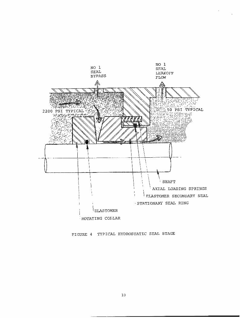
2 .3 Hydrostatic Seals
The hydrostatic seal, conceptually represented in Figure 4, is a self
regulating force balanced sealing device. The balance is achieved by
summing the axial closing spring and pressure forces behind the station
ary seal ring with the force generated by the opening pressure force
in the the gap between the rotating collar and the stationary seal
ring. The opening force results from the radially decreasing gap (in
the direction of leakage flow) between the seal faces which forms a
converging film thickness in the sealing interface. This tapered gap
geometry produces a higher film pressure opening force between the
collar and stationary seal faces than that which would exist were the
faces flat and parallel. The fluid being sealed flows radially inward
toward the shaft in the converging direction of the tapered seal face.
If the seal ring tends to close, the interface pressure increases and
the ring is forced back to its steady state operating position.
9
NO 1 SEAL BYPASS
NO 1 SEAL LEAKOFF FLOW
' SHAFT
AXIAL LOADING SPRINGS
ELASTOMER SECONDARY SEAL
STATIONARY SEAL RING
1ELASTOMER
ROTATING COLLAR
FIGURE 4 TYPICAL HYDROSTATIC SEAL STAGE
10

Conversely, if the seal rings tend to open, the interface pressure
decreases which reduces the load carrying capacity of the film such
that the axial pressure/spring force restores the seal to its steady
state position. Thus, the interface film profile serves as a position
feedback mechanism to provide a positive restoring force to the seal
ring for steady state gap separation. Because of its relatively large
separation gap, leakage through the hydrostatic seal interface is in
the range of three to five gpm.
Seal assemblies designated as hydrostatic are also multi-stage devices
as shown in Fig. 5. Only the first high pressure stage of these seals
are hydrostatic in nature with subsequent sealing stages operating on
the thin film hydrodynamic principle. Therefore the assembly may be
referred to as hybrid-hydrostatic. The first hydrostatic stage operates
with full system differential pressure of approximately 2150 psi. The
second stage pressure reduction is approximately 50 psi, and third
stage, which is as a vapor seal, sees a differential pressure of less
5 psi. The second seal stage is designed to contain the full system
pressure in the event that the high pressure stage fails. In this
condition, however, seal leakoff rate increases to about 25 gpm,
2.4 Pump Shaft-Seal Interface
Axial shaft displacement of approximately one-eight of an inch must be
accomodated within the seal assembly. This places stringent operating
limits on the back-up springs and on the allowable distortion/displace
ment of the secondary elastomeric seals. Such axial motions arise
from:
1)
2)
3)
4)
5)
11
The downthrust due to the weight of the rotating assem
bly;
Pump shaft length changes because of steady state and
transient thermal system variations;
The oil lift system which lifts the pump shaft off the
thrust bearing at startup to reduce motor starting
torque load;
The resultant axial thrust loads on the pump shaft; and
The motion resulting from the motor rotor seeking its
magnetic center.

NO. 3 SEAL LEAKOFF 100 CC/HR
NO. 2 SEAL LEAKOFF 3 GPH
NO. 1 SEAL LEAKOFF 3 GPM
NO. 1 SEAL BYPASS
(NORMALLY CLOSED)
3 GPM TO NO - 1 SEAL
£ PUMP SHAFT
STATIONARY SEAL RING
ROTATING COLLAR
3RD STAGE LOW PRESSURE HYDRODYNAMIC SEAL
2ND STAGE LOW PRESSURE HYDRODYNAMIC SEAL
1ST STAGE HIGH PRESSURE HYDROSTATIC SEAL
PUMP END
FIGURE 5 A 3-STAGE HYBRID HYDROSTATIC SEAL ARRANGEMENT
12
The desired fluid film gap between the mating seal faces is in the
order of 40 and 400 microinches respectively for hydrodynamic and
hydrostatic seals. The ratio of a typical 1/8 inch shaft displacement
to the relatively small gap which must be maintained is approximately
300 to 1 for the hydrostatic seal and 3000 to 1 for the hydrodynamic
seal. Although the hydrostatic seal face separation is greater than
ten (10) times that of its hydrodynamic counterpart, its characteristic
outflow leakage is more than 100 times that of the hydrodynamic configu
ration. Because of the relatively small hydrodynamic gap, face flatness
and roughness is critical to seal functional integrity. Hydrodynamic
seal faces are precision lapped for flatness within 20 microinches
with comensurate surface finishes. Since there is such closeness of
these sealing surfaces, materials used for the rotor and stator faces
must tolerate continuous low speed and intermittent high speed contact
without serious wear or galling on either face. Material combinations
such as titanium carbide for one of the rings and a carbon composite
mating ring is an example of such a compatible set used for hydrodynamic
seals. On the other hand, hydrostatic seals cannot tolerate any
contact between mating seal faces even at low/start-up speed conditions.
Pressurization of the hydrostatic seal cavity must be attained prior
to rotational shaft motion. The establishment of a hydrostatic condi
tion must be provided to separate the seal faces prior to operating
the pump. Thus although a greater gap distance is maintained, the
tolerance for dynamic contact of the seal faces is much smaller for
hydrostatic seals. Since the relative merits of the hydrodynamic and
hydrostatic configuration are not at issue herein; we merely describe
the general design highlights and their attendant operating constraints
to support the development of the operational guidelines that will
follow.
Lateral and angular displacement between the stationary and rotating
seal faces results from:
1) Motor-pump shaft centerline misalignments;
2) A hydraulic moment unbalance caused by a lack of concen
tricity between the rotating and stationary seal faces;
3) Thermally induced seal ring deformations which change
the size and shape of the gap between the seal faces;
4) Shaft or seal support deflections allowing a shaft tilt
13

which in turn induces a wobble in the rotating face;
5) Steady state and dynamic hydraulic impeller forces; and
6) Shaft loads due to an unbalance in the rotating assembly.
An angular displacement (tilt) of one of the mating seal faces with
respect to the other causes a gap closure at one point and an opening
at the diametric opposite point. Since proper sealing requires a
small gap size iniatially and since seal ring diameters are large
(i.e., to 7 to 12 inches typically), very small tilt angles can quick
ly cause rubbing contact between the sealing faces on one side while
concurrently opening up the leakage path on the other side. As previous
ly noted, rubbing contact between the mating faces, at the high rotation
al speeds of operating pumps, accelerates wear and generates considerable
heat energy which reduces seal life drastically and/or rapidly induces
catastrophic seal failure.
Lateral displacements of the shaft at the seal assembly, for reasons
noted, can cause cyclical compression and relaxation loads on the
secondary elastomeric seal. This in turn results in secondary seal
rubbing against its mating walls with attendent wear in the form of
fretting which induces failure of this seal element. Excessive internal
seal heat generation or lack of adequate cooling to the seal assembly
further aggravates this problem since elastomers harden under excessive
heat loads. Since proper seal tracking force transmittal requires
compliant elastomer properties, such hardening adversely affects the
ability of primary seal faces to maintain a proper gap clearance.
However, some lateral cyclic (orbiting) motion of the rotating seal
ring against the mating surface may be beneficial since it provides an
increased seal gap flow which increases the heat removal capability
and decreases seal face wear.
Water contaminants in the form of system corrosion products, wear
residue from system components or foreign materials introduced during
assembly, fill or maintenance can cause seal failure. In the case of
hydrodynamic seals, such contaminants may create unequal staging
differential pressures by partially or totally blocking the staging
flow path. This will cause dry running in the seal stages which have
lost the staging pressure differential. Additionally, small particle
transport to the seal interface will cause accelerated wear through
14

the destruction of the highly polished lapped seal faces.
Contaminants are equally damaging to the hybrid-hydrostatic seal
mechanization. Remember that two of the three seal stages in this
assembly are of the hydrodynamic type and therefore the proceeding
discussion applies. In addition, larger particles find easier entrance
at the opening of the taper wedge interface and may build-up blocking
dams which upset the load carrying capacity of this seal to the point
of collapse of the separating film.
Since the operating environment can subject the seal to numerous
cyclical and random hydraulic, mechanical, and thermal forces, it is
of paramount importance that the seal auxilliary systems be capable of
modifying and maintaining the seal environment to less stressful
levels. The foregoing discussion does not delve deeply into seal
operating principles. It is only intended to heighten the reader's
awareness of:
1) The sophistication and sensitivity of the sealing
device;
2) The demanding operating environment;
3) The tight performance margins placed on the seal; and
4) The sensitive interfaces between the seal and other
system components and subsystems on whose proper
performance seal reliability and longevity depends.
3.0 SEAL AUXILIARY SYSTEMS
Clean water with both temperature and pressure controlled within
narrow limits, must be provided for proper and reliable shaft seal
operation. Seal water delivery systems may vary in physical configura
tion and design detail, but they are functionally similar and provide
for:
1) Delivery of sufficient flow of water at the required
pressure within prescribed temperature limits;
2) Prevent ingress of contaminants to the seal cavity;
3) Collection and return of the seal leakage flow;
4) Collection and return of the controlled staging flow
15

water (leak-off);
5) Pressurization of the seal assembly prior to pump
start-up to assure separation of hydrostatic seal
faces;
6) Venting of gas voids trapped or carried to the seals by
circulating water.
Some systems supply the pressurized seal staging flow from an independent
injection subsystem, while other designs use cooled primary coolant as
the staging flow source, or a combination of each. Whereas numerous
seal problems have been attributed to the direct use of primary coolant
in some systems, others are operating problem free with primary coolant
as the sole source of seal water supply. More will be said of this
subsequently.
To properly provide the above noted functions, and to assess the
integrity of the seal on a continuous basis requires pressure, flow,
temperature, and motion sensors, with attendant read-outs and recording
devices.
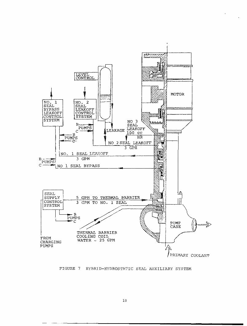
Typical seal auxiliary systems for hydrodynamic and hydrostatic seals
operating in MCP's are shown in Figures 6 and 7 respectively. In the
case of systems with injection, an independent source provides the
high pressure cooled water to the seal. The injection supply is at a
slightly higher pressure than the pump case pressure. As a result,
some of the injection supply enters the primary coolant loop and the
balance flows through the seal assembly. In this manner the primary
coolant is blocked from entering the seal assembly. Water cleanliness
is beneficial to seal operating integrity. Debris introduced into the
primary coolant loop during assembly/maintenance and the transport of
corrosion products (crud) generated in the primary coolant loop can be
avoided by using an independent injection water supply to the seal.
The use of injection provides seal water supply redundancy. In an
injectionless system, seal cooling and lubrication is accomplished by
circulating the high pressure primary coolant through heat exchangers
and then introducing the reduced temperature coolant to the seal.
The heat exchanger is cooled by low pressure, externally supplied
component cooling water (CCW). In this case, single point loss of
16

SEAL LEAKAGE-
i CCW CONTROL SYSTEM
TO PLANT SYSTEM
VENT CONTROL! SYSTEM I
SEAL INJECTION CONTROL SYSTEM
PUMP CASE
PRIMARY COOLANT
FIGURE 6 HYDRODYNAMIC SEAL AUXILIARY SYSTEM
17
LEVEL CONTROL
NO. 1 SEAL BYPASS LEAKOFF CONTROL SYSTEM
PUMPS
i NO. 2 SEAL LEAKOFF CONTROL SYSTEM V^
! LEAKAGE
NO 3 SEAL LEAKOFF 100 cc i HR
NO 2 SEAL LEAKOFF 3 GPH
SEAL LEAJ<OFF 3 GPM
NO 1 SEAL BYPASS
SEAL SUPPLY CONTROL SYSTEM
5 GPM TO THEPvMAL BARRIER 3 GPM TO NO. 1 SEAL
FROM CHARGING PUMPS
THERMAL BARRIER COOLING COIL WATER -25 GPM
PRIMARY COOLANT
FIGURE 7 HYBRID-HYDROSTATIC SEAL AUXILIARY SYSTEM
18

CCW will adversely affect seal life. Numerous seal failures have been
reported subsequent to interruption of the cooling water supply. The
use of an independent seal injection does not automatically provide
reliable cooling redundancy unless the CCW heat exchanger capacity is
adequate to handle the additional heat load imposed on it when the
injection supply is lost. Several instances have been noted where the
loss of injection precipitated seal failures because of the thermal
transient associated with this event.
Reactor coolant is normally above 550°F and the desired seal cavity
operating temperature is below 150°F. It is important to maintain a
steady seal cavity temperature and limit the thermal gradient within
the seal caused by upset transients. Whereas the seal operating
temperature is determined, mostly by the elastomer thermal limits, and
the need to keep seal face leakage (which is nearly at atmospheric
pressure) below flash point temperature, the thermal gradient limits
are set by the small amount of physical growth and distortion tolerable
by the seal faces and non-rotating back-up rings. Since nominal
sealing gaps are of the order of 20 to 40 microinches, minute levels
of distortion can alter the gap significantly and possibly cause
contact between the sealing faces. Such contact further aggravates
the condition and, if sustained over a prolonged duration, will initiate
the failure mode. Distortions in the form of converging and diverging
gap between the seal faces are shown in Figure 8. The distortion
sensitivity of the seal rings is dependent on materials used and their
geometric structures. One can establish designs which make the seal
ring highly insensitive to thermal transients or conversely, design
seals highly dependent upon an unvarying thermal environment. Neither
of these extreme conditions are practical and, therefore, all configura
tions will exhibit some dependence of the physical stability of seal
rings on auxiliary cooling. Since the designer cannot completely
eliminate thermally induced distortions, the design must be aided by
auxiliary equipment which maintains a reasonably stable thermal environ
ment. Conversely, since the auxiliary system cannot provide a totally
stable thermal environment for all operating conditions, the seal
design must be tolerant to a reasonable level of thermal transients.
Whereas work towards defining the design related seal stability para
meters are being pursued in other tasks of this program, the intent of
this document is limited only to the operational aspects of the
19

SEAL RINGS LEAKAGE FLOW
a DIVERGING IN DIRECTION OF FLOW
PUMP
SEAL RINGS LEAKAGE FLO-J
b CONVERGING IN DIRECTION OF FLOW
FIGURE 8 THERMAL AND HYDRAULIC ELASTIC RING DISTORTION
20

auxiliary systems which provide the suitable seal life sustaining
environment.
Auxiliary systems are comprised of all or some of the following
components:
pumps;
pump drives;
fluid transmission lines;
reservoirs;
accumulators;
filters;
heat exchangers;
pressure/flow controllers;
pressure/flow/temperature sensors; and
collection tanks.
In some cases, the supply from a single injection charge pump is
branched to feed multiple primary coolant pumps. In other systems, a
dedicated injection pump is provided for each pump. These high
pressure water systems are also subject to failure and must be repaired
and/or serviced. Check valves in the supply and return legs assure
the containment of the primary coolant when interruption of the injec
tion supply occurs.
When the typical hydrodynamic seal auxiliary system is injectionless,
reactor coolant, cooled by heat exchangers contained within the pump,
provides the cooling flow to the seal cavity. These heat exchangers
are cooled by low pressure component cooling water. The controlled
bleedoff (CBO, leakoff) includes the seal leakage flow. As already
noted, this leakage flow is normally very small (on the order of one
gph) and must increase significantly before it can be reasonably
sensed. Because of the fact that bleedoff flow changes of such small
magnitude (which are within the threshold sensitivity of the sensors)
require detection, tracking of bleedoff trends via flow measurements
is not always reliable. In addition to staging flow (CBO) instrumenta
tion, there are sensors to monitor pressure and temperature in the
seal cavities. Alarms are often provided to annunciate dangerous
staging flow or seal cavity operating temperature conditions.
21

Functional integrity of seal staging is determined from differential
pressure measurements across each seal stage. In systems without
injection, high seal leakage flow is reflected by the temperature of
water in the lower seal cavity and since measuring temperature is
easier than detecting small changes in flow, some systems do not rely
on controlled bleed off flow measurement. In injectionless systems,
the lower seal cavity water temperature readily reflects the rate of
leakage because the staging water comes from the primary coolant which
is cooled by the internal pump heat exchanger. An increase in leakage
increases the flow of high temperature water through the heat exchanger
thus increasing the heat load. Leakage trends can thus be tracked by
temperature measurements of the seal cavities.
It is also possible to detect increases in inner stage seal leakage by
monitoring and trending the pressure in the upper seal stage cavities.
For instance, increasing pressure may be caused by an increase in
either the seal face leakage or a change in the controlled bleedoff
flow of the lower or preceding stage. On the other hand, a decreasing
upper seal cavity pressure may be indicative of an increase in leakage
to the seal leakage collection vessel.
In injection fed hydrodynamic seals, there is only a slight seal
cavity temperature change for a relatively large increase in seal
leakage because the pump is supplied by a fixed quantity of injection
water and this flow will distribute itself according to the flow
impedance ratio of the seal upflow and the pump downflow paths.
Typically about 5 gpm of injection flow is supplied to the pump in the
area of the lower seal cavity, of which approximately 1 gpm is normally
provided for staging coolant flow. When seal face leakage increases,
the upflow branch impedance decreases and the upflow rate of cool
water increases while the downflow decreases by an equal amount. The
increased upflow rate of cooled water will compensate for increased
seal heating and keep the cavity temperature fairly constant. As a
result, temperature does not reflect seal leakage as readily as in
injectionless configurations. However, when injection supply is lost,
the seals are cooled by the upflow of cooled primary water as in
injectionless systems. As previously discussed, if the combined
staging and seal leakage flow exceeds the capacity of the component
cooling water (CCW) heat exchangers, the seals will overheat and have
22

a high probability of failure. Therefore, when hydrodynamic seal
auxiliary systems are configured with injection, the total leakage
through the seal must be limited to the rate which can be handled by
the (CCW) heat exchanger alone. This dictates pump shut-down when the
heat exchanger safe capacity level is reached. An example of such a
situation taken from Reference 2 illustrates this type of a problem.
At one installation, seal injection water was lost everytime the
reactor scrammed. The source of seal injection water at this facility
is the control rod drive (CRD) supply. After the scram the demand of
the CRD accumulators exceeded the CRD supply capacity and cool water
was not available to the pump seals. This condition contributed to
several failures. To solve the problem, the accumulator fill rate was
limited by throttling. This maintained sufficient injection supply
water to the seals during recovery from the scram incident.
Another example (from Reference 2) of how one operating plant eliminated
seal failures which occurred because of injection supply interruptions
was to rate limit the controlled bleedoff flow (which includes the
seal leakage). In this way when injection is lost, the seal leak rate
does not cause an increase in primary coolant upflow through the CCW
heat exchanger beyond the capacity of the heat exchanger. This prevents
excessive heating (up-shock) of the seal by the higher temperature
upflow water and prevents thermal down-shock when injection is re
established.
Further on the same subject, a few MCP and RCP users have expressed a
need and/or desire to employ a pump as a standby unit under full
system pressure and temperature. This condition can create a serious
temperature situation for the elastomers of the seal assembly in
injectionless pumps. The idle pump may not generate sufficient internal
seal water circulation through the seal heat exchanger because the
internal recirculation pump is stationary. The elastomers at higher
than normal operating temperatures will experience degradation through
accelerated age hardening. These illustrative examples are provided
only to stress the need for extensive Failure Mode and Effects analysis
(FMEA) which includes not only the seal and what may normally be
defined as the seal auxiliary system but also all equipments and
subsystem interfaces which affect the performance of the sealing
system.
23

Failures due to inadequate component cooling have many underlying
causes. A number of these can readily be avoided or, as a minimum,
their incidence rate can be greatly diminished.
Excessive Control Bleedoff Flow
Some systems which operate without injection contain valving to shut
off the staging flow bleedoff line when the flow increases to approxi
mately 2 gpm. A bleedoff flow of this magnitude is indicative of the
failure of one or both of the first two sealing stages and excessive
leakage of the third stage. Increased seal leakage causes an increase
in primary coolant flow through the seal water heat exchanger. When
this leakage becomes excessive, the hot primary coolant water flow
rate exceeds the capacity of the pump heat exchanger. When the bleedoff
flow exceeds the maximum heat exchanger capacity (i.e., approximately
3 gpm for typical systems) the control bleedoff (CBO) line is often
closed to prevent either excessive heating of the seal or to retard
the seal heat-up rate. However, such closure of the CBO flow places
full system differential pressure across the third stage seal because
the pressure staging mechanism, which depends on staging flow for
proper operation, is inoperative and all seal cavities rise to system
pressure. Both of these operating conditions are excessively stressful
for the seal, but the former is considered the more favorable of the
two undesirable conditions. When this occurs, the pump should be
shutdown as quickly as possible because a failure of the third (or
fourth) stage seal will result in a large outflow of reactor primary
coolant. Thus the CBO valve closure only minimizes the probability of
a catastrophic seal failure and accepts the assumption that one seal
in fact has failed. Once having incurred excessive CBO flow, operator
action will not alter the apriori seal failure condition if in fact
the seal is in a failed state. If the closure of the CBO line was
erroneously initiated and the seal is not in a failed state, the
closure will force seal failure because, as previously noted, all
except the last stage sealing faces run dry (zero pressure differen
tial) under zero staging flow conditions. In this case operator
action may reduce the chance of failure by re-establishing the CBO
flow. The point is to quickly assess the true state of the seal and
take rapid action to:
24
1) Shut the pump down to minimize chances of a primary
coolant spill because the seal is in a failed state;
or
2) Open the CBO valve to re-establish staging flow to
preclude having that closure cause a seal failure.
The proceeding discussion assumes that plant operating conditions
preclude the immediate shutdown of the pump containing the failed or
suspect seal. Conditions may exist which require operating the failed
pump in order to maintain required reactor heat removal rates. Such
decisions must be based on the plant multiple pump operating configura
tion at the specific time that the CBO line is closed. However, from
a seal standpoint only, it is difficult to postulate any conditions
for which the CBO line should be closed and similarly to find reasons
why not to immediately take the pump off line when CBO flow is indicating
as being excessive. If the seal is in a failed state, prolonged
running is highly inadvisable. If the indication of excessive leakage
is erroneous (i.e., because of sensor failure which closes the CBO
valve, etc.) then the seal is not failed and continued operation under
these conditions is equally inadvisable since it (closed CBO) may
force the seal to actually fail. Such continued operation imposes a
severe overstress on these close tolerance sealing elements. Therefore,
operating procedures should be closely reviewed and re-examined to
identify clearly the plant conditions which allow immediate pump trip
when excessive CBO flow is indicated instead of closing the CBO valve,
3.2 Loss of Component Cooling Water
The specific causes that result in the loss of component cooling water
are varied but a general thread of commonality does exist. Therefore,
some of the items discussed herein may not be readily visible to a
specific plant design, but within the overall text, one will find some
items which reflect a potential failure forcing mode at every operating
facility.
Component Cooling Water (CCW) is critical for reliable seal performance
in systems which operate without injection because seal heat removal
is totally dependent on the supply of CCW to the pump heat exchanger.
Many utilities have reported seal failures subsequent to loss of CCW.
25

Such CCW supply interruptions were caused by various reasons and are
listed here to allow the reader to relate to similar potential situa
tions which may be possible at his facility of interest.
1. Cooling water intentionally shut off (possibly following
some emergency incident) and not re-instituted in a
timely manner.
2. Loss of power to CCW pump drive.
3. Instrument error causing a shut-off of CCW.
4. CCW system leak.
5. Loss of the instrument air supply. Such air is sometimes
used for control of valves, regulators, etc. in seal aux
iliary systems.
All systems contain redundant means to provide CCW to the main coolant
pumps. Variations may exist between power plants with respect to how
these redundant CCW sources are brought on line and the time delays
between the initial CCW loss and the initiation of its back-up. Main
coolant pxamps have been kept operating in the absence of CCW, resulting
in shaft seal failures. These incidents could have been avoided if
operating procedures contained actions to assure that the flow of CCW
was maintained. These procedural actions could be further enhanced if
CCW flow integrity were flagged as high priority item during start-up,
normal operation and recovery conditions.
Shutting off CCW flow in an operating pump in order to repair auxiliary
system components or leaks is a high risk decision. Unless valid
reasons exist to assume this high risk, the reactor coolant pump
should be brought off-line prior to shutting off the CCW flow.
Loss of cooling water false alarm indications have also been a major
seal failure forcing mode. In these instances even though the cooling
flow is actually maintained, the response to the false indication is
to close the CBO line and thus block the flow of the supposedly uncooled
primary coolant through the seal. As previously noted, such closure
26

will force a seal failure if the CBO valve is not re-opened or the
pump quickly taken off-line. The CCW loss of flow false alarm is
judged to be the cause of five (5) seal failures at one utility. The
false indication was, in this case, the result of a computer/valve
control circuitry malfunction. The problem was further aggravated
because the monitoring of the status of the CBO valve was not given
high priority in the procedure and the CBO flow indicator was not
visible. Warning of the closed valve status through annunciating
alarms was not prominent. Thus a minor undetected circuit problem
giving false information resulted in action which seriously damaged
the seal. All operating procedures should recognize that no plant is
immune to these generic problems. Procedural account of seal status
via temperature and pressure instruments coincident with a visible and
audible CBO valve status indication should be implemented. At another
utility, an instrument air failure resulted in the loss of CCW to all
operating reactor coolant pumps and caused the failure of each pump
shaft seal. Several years later, the situation repeated itself such
that the loss of eight seals have been incurred at this site. On the
surface it appears that the system mechanization called for CCW valve
closure when instrxoment air was lost or the valve in the CCW supply
line was held open by instrument air supply pressure. If flow control
valving is desired in the CCW supply line to maintain uniform CCW
temperature (or for any other reason), it should be mechanized to fail
open. However one should critically examine the need to place an
automatic flow control valve in this critical path. If, however, a
remotely controlled valve is placed in this critical flow path, it
should contain mechanical limit stops to prevent its full closure.
This would prevent inadverdent valve closures. For contingency closure
requirements of the CCW line, a manual shut-off valve may be utilized.
The status of the CCW supply to the pump should be given high priority
similar to that recommended for the CBO flow. Both are crucial to
seal operational integrity. Modified procedures recognizing this
criticality along with read-out devices and annunciating alarms within
operator audible range and view are strongly recommended. From purely
a seal point of view, there is no valid reason to continue the running
of the pump when CCW circulation is curtailed. However, with other
factors involved, compromising decisions must often be made by the
utility and its design/operating team.
27
3.3 Contaminated Seal Supply Water
Numerous reports citing the presence of foreign material in damaged
seals are indicative of the importance of internal cooling water
cleanliness for seal reliability. Some literature sources note that
seals operating in several injectionless systems are of comparable
reliability to those which are injection fed. Such observations have
led to conclusions which question the value of an independent seal
water injection supply. Primary water cleanliness varies from one
system to another and, within a single system, may vary at different
system locations. Thus, such water quality can vary from pump to pump
and/or from time to time at the same pxomp. For these reasons, it is
understandable that a seal will yield satisfactory life performance
characteristics in some injectionless installations and have a high
mortality incidence in another. The goal is a constant supply of
clean seal cooling water, and this goal is best reached through the
use of an independent injection supply.
All users should examine their physical system design towards under
standing of shaft seal vulnerability to damage from debris. This
review should consider:
1) Location of the pump relative to system cleanouts;
2) Location of system fill points;
3) Location of other components which require maintenance
from time to time; and
4) The location of concentration points for corrosion
product (crud) collection.
One utility operating witH injectionless pumps has noted that seals
from one reactor recirculation pump have consistently been dirtier
than those from other pumps in the same system. They note that the
suction for the loop cleanup is just upstream of this pump and postulate
that the cleanup flow concentrates crud and other debris in the vicinity
of this pump, a portion of which is transported to the shaft seal.
An independent injection supply provides a clean cooling water flush
through the seal and further prevents the entrance of debris and crud
found in primary coolant water. Injection systems, and the operational
28

procedures used with injection supplied seals, can, however, create
seal failure forcing problems. For hydrodynamic seals, these problems
are basically the same as those already noted with loss of CCW and CBO
valve closure. Loss of injection could readily be tolerated from a
cooling viewpoint, but instances have developed where this has not
been the case. For example, the loss of injection leaves an operating
system in the injectionless configuration with the same seal failure
forcing modes as previously noted. Therefore, the procedural cautions
and priorities suggested for injectionless seal operations are pertinent
also for the injection configured system. Perhaps with injection
supplied seals, the loss of CCW and CBO valve closure related problems
may be more pervading because of the subtle human tendency to rely too
heavily on the redundant cooling capability. Thus, if CBO flow becomes
high (but supportable with injection cooling) and injection is lost,
the redundant cooling capacity can readily be inadequate without
operator appreciation or notice of this condition. This has occurred
at several operating plants.
The Reference 1 and 2 seal reliability oriented surveys have noted the
existence of crud in seals disassembled for repair and refurbishment.
A great amount of information is available on corrosion product
(crud) deposition (See Reference 4). Such deposition occurs at
orifices, low velocity regions or where variation occurs in coolant
temperature. Heat exchangers are prime examples of the latter.
Corrosion products reduce heat transfer capacity and can foul instrumen
tation. Shaft seal literature to date has not identified coolant heat
exchanger fouling as a problem. It is briefly mentioned here as a
potential problem inducing source not yet readily recognized. Certainly
the physical mechanism exists and could be the cause or partial cause
of failures. Usage time will only increase the performance degradation
of heat exchangers.
With respect to instrumentation, blocked sensing lines and dirty/
fouled contacts are the second largest cause of instrumentation failure.
It can be readily concluded that contaminated seal water has a signifi
cant effect on seal reliability and longevity.
A detailed system engineering evaluation and Failure Mode and Effect
29

Analysis (FMEA) of the auxiliary system is required to identify all
possible failure forcing modes. Subsequent to this identification,
these failure modes should be grouped into a minimum set of categories
which reflect common procedural recovery methods required to minimize
catastrophic shaft seal damage. With injection supplied water, a
single point failure in the seal cooling system should never cause a
seal failure since operating procedures can be made complete enough
(for all possible operating conditions) to initiate timely operator
recovery action.
3.4 Venting Procedures
Venting of entrained primary coolant system air is accomplished
through the pump shaft seal because it is the highest elevation
within the pump with a continuous path that contacts the primary
coolant water. Most designs permit the flow of entrained air from
each seal cavity through vent ports. Such venting is controlled by
manually operated shut-off valves in each vent line.
Seal problems have resulted from using incorrect vent valve open/close
operating sequence. Improper vent valve operation can reverse the
pressure on secondary sealing elements such as "U" cups, thus relieving
the preload on the "U" cup follower, unseating the "U" cup and/or
creating other problems such as drive lug loosening/dislocation.
Although such problems have occurred, all were humanly induced and can
be procedurally controlled to prevent occurrence. The procedural
methods to prevent recurrence can be greatly enhanced by highly visible
markings to code the vent valves or to vent through the CBO line only
(as some operators are doing now).
In many cases, venting procedures call for the partial opening of
valves during the venting process. The only way to properly set the
valve is by knowing the flow conditions through the valve. Instrumenta
tion readouts (if any) however are generally located in the control
room away from the technician performing the function. As a result,
human judgement is often substituted. A simple design fix is available
to ease this situation through incorporation of an in-line orifice or
use of a small valve of predetermined flow area. Either of these
would allow for full- open, full-close valve positions and thus eliminate
30

any guess work involved in "proper" valve settings.
Many venting procedures require several short periods of pump operation
to impart fluid "churning" in the seal cavitites to aid the transport
of entrapped gas to vent port locations. Procedural care is critical
to insure against running the seal in a partially "dry" state. Thus,
it is adviseable for the first phase of venting to proceed through the
CBO line for an extended time without any pump starts prior to the
second phase of the bleed process through the individual seal cavity
lines.
Through appropriate design geometry, full self venting of the seal
cavity and CBO/leakoff flow paths can be assured, greatly reducing the
human error element in the venting process. Note also that for injec
tionless hydrodynamic seal cooling systems, the venting process is
continuous through the CBO flow line during normal pump operation.
Injection cooled systems prevent venting of primary coolant entrapped
(air when injection water is being supplied to the pump) because the
pressure of the injected water must be greater than the primary coolant
pump case pressure. This implies that ptimps with injection fed seal
cooling systems require somewhat more attention to the system vent
process than those with injectionless cooling systems.
Further support of the desirability of self vent designed seals is
given by the experience of seal failures which the user attributed to
a leak in the seal cavity vent line. Since this system was injection
less, the vent line leak allowed excessive hot water into the seal
because the flow exceeded the pump heat exchanger capacity. A leaky
instrument line can also cause such a condition. Note that self
vented seals preclude the need for individual vent lines which are
potential fluid leakage paths. Prior to the discovery of the root
cause of this problem, the system was retrofited with injection capabili
ty. The addition of a properly sized injection supply should be
viewed as a valuable addition to a more reliable seal cooling system
even though the prime failure cause in this instance was a vent line
failure.
The fact that the user concluded that a vent leak was the cause of a
chronic seal overheating problem focuses attention on the importance
31

of thermal instrumentation and annunciating alarm/readouts. These
could flag attention to such impending problems. In this instance,
the sensors and read-out devices were either inadequate or were ignored.
As a result, several failures were experienced. This is another
example of the numerous hardware mishaps for which possible procedural
solutions exist through better use of instrumentation.
Hydrostatic seal supporting systems are quasi self venting through the
number one seal bypass line which is open prior to pump start, and
also through the high flow number one leakoff line during pump operation.
The venting of the number three seal cavity may present problems
because of the low leakoff rate associated with this seal and the
location of the leakoff port in relation to the location of the sealing
faces.
As previously noted, the venting process normally requires the opening
and closing of vent and return line valves. It is of utmost importance
to verify full flow of water in the CBO line and correct staging
differential pressure subsequent to the last valve handling section of
the venting procedure prior to startup of the pump,
4.0 Instrumentation
Proper shaft seal performance is dependent on the ability to measure
and control critical seal operating parameters. To enhance the relia
bility of seal operations, it is important to track the time variant
behavior of critical seal operating parameters such as leakage, bleed
off /leakoff flow rates and seal operating pressures and temperatures.
To do this requires the use of sensors, control hardware, signal
conditioning electronics and read out devices which will be refered to
in the lumped term of Instrumentation and Controls (I&C) . Failure of
I&C elements may lead to ultimate failure of the pump shaft seal. In
order to optimize the I&C role in attaining a high seal reliability,
it is necessary to identify the major causes of I&C failures so that
reliability oriented improvements in maintenance, testing and operating
procedures can be implemented.
An EPRI sponsored investigation on the characteristics of I&C system
failures in light water reactors (Reference 5) identifies such failures
32

using the following categories:
a) Random failures: Instrioment and Control elements which
fail when operated within design specifications;
b) Infant Mortality/End of Useful Life (wear out) failures;
and
c) External, Induced Failures: Those failures contained
m the total population of (a) and (b) above which make
the random and infant mortality/wear out failure rates
appear higher then they actually are because they are
interspersed within these sub-groups without belonging
to those sets.
This report focuses attention on item (c) above, since it is the prime
area for further operational improvements through procedure and minor
design actions. Prime dependence is made on Reference 5 for the
general I&C failure summary presented herein.
A degree of uncertainty often exists m I&C failure classifications
because the specific cause of failure is unknown at the time the event
occurred. The Reference 5 investigation, however, was able to classify
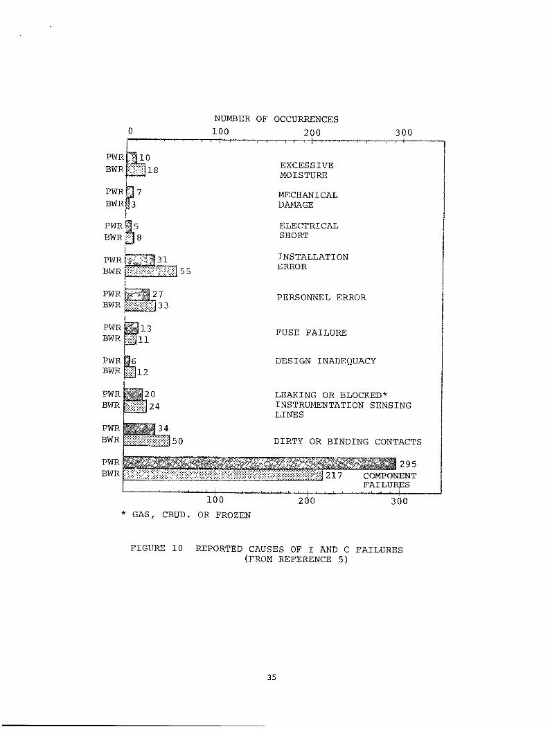
the ISC related failures into groupings shown m Figures 9 and 10.
The report notes that the frequency of failures attributed to environ
mental affects is probably underestimated and that a more significant
portion of all ISC failures are actually due to adverse environment.
Figure 9 identifies ISC failures in PWR & BWR installations into two
categories: Component Failures and Other Failure Modes. Note that
the environment induced failures are lumped into the "Other Failure
Mode" category. Figure 10 shows the detail breakdown of these failure
modes from which at least the following three items are attributed to
being environmentally induced.
Such environmentally induced failures include:
BWR PWR
a) Blocked Instrumentation Lines 5% 4%
b) Fouled or Binding Contacts 10% 7%
c) Excessive Moisture 4% 2%
TOTAL 19% 13%
33

COMPONENT FAILURE
295
217
w T%.
214 OTHER FAILURE MODES (E.G., PERSONNEL ERROR, DIRT OR BINDING CONTACTS, BLOCKED OR LEAKING INSTRUMENT SENSING LINES,
3 EXCESSIVE MOISTURE).
« ft
FIGURE 9 CAUSE OF INSTRUMENTATION AND CONTROL FAILURES (FROM REFERENCE 5)
34
NUMBER OF OCCURRENCES
100 200
PWR
BWR
PWR
BWR
PWR
BWRt
PWRf
BWRf
:^io <B;1i8
f is 3B
-̂ '̂ 1-
PWR BWR
PWR ^ 1 3 BWR plfll
PWR BWR
PWR BWR
PWR BWR
PWR BWR
20 24
300 -r-4
EXCESSIVE MOISTURE
MECHANICAL DAMAGE
ELECTRICAL SHORT
INSTALLATION ERROR
PERSONNEL ERROR
FUSE FAILURE
DESIGN INADEQUACY
LEAKING OR BLOCKED* INSTRUMENTATION SENSING LINES
DIRTY OR BINDING CONTACTS
mfcsmmk •&dW:Wi^Jfimmm&^ 217 COMPONENT FAILURES JRE£
100
* GAS, CRUD. OR FROZEN 200 300
FIGURE 10 REPORTED CAUSES OF I AND C FAILURES (FROM REFERENCE 5)
35

However, the current percentages are significant and justify that
utility attention be given to ISC performance improvements in these
areas.
The general summary presented is only for overview and guidance
purposes to the specific shaft seal related I&C items. For example,
the shaft seal leakoff flow rate is critical to knowing the functional
integrity of both hydrostatic and hydrodynamic seals, These two seal
types require differing flow measurement mechanizations because of the
great difference in flow magnitudes being measured. In operating
hydrostatic seals, contact between seal faces is intolerable and
leakoff flow is indicative of required seal face separation. In
hydrodynamic seals, low leakage flow rate is indicative of the thin
film gap separating the faces of the last sealing stage while a known
higher flow rate associated with the CBO flow line indicates both a
satisfactory staging flow and proper leakage through the first and
second stage seals. The instrumentation range should encompass CBO
flow from normal up to a level at which the cooling water heat exchanger
capacity is exceeded. As noted before, if injection is lost or in
injectionless systems, this is the point at which seals can be thermally
overstressed to failure. The measurements should be in continuous
form as opposed to limit readouts/ alarms. It is important to measure
actual flow as opposed to only knowing whether a limiting value has or
has not been reached. In the latter case one does not know whether
the limit value is reached or greatly exceeded.
The only measurement associated with venting procedures is the visual
observance of air bubbles in the vent flow lines. A few utilities
have installed clear plastic tubing for such observations. The other
users depend on venting for a predetermined time for accomplishing
system air bleed and have no capability of verifying the effectiveness
of the procedure. All should use either a visual verification of the
bleed process or add instrumentation in the bleed lines or bleed sump
to ascertain the air free quality of the seal vent water prior to pump
start up.
Environmentally induced failures are primarily associated with signal
conditioning, readout and alarm annunciating devices. Note that 19%
of BWR and 13% of PWR ISC failures are caused by environment category
36

conditions. These failures may be reduced by upgrading cleanliness
conditions, reducing temperature and hiamidity variations at sensitive
ISC equipment. Flow, pressure, temperature and vibration sensor
failures need to be reviewed with respect to the level of redundancy
utilized and the physical location of readouts and alarms with respect
to control room personnel. The level of I&C environment/procedural
control, redundant mechanizations of sensors/ readouts, prominent
relocation of readouts/alarms, etc., is best determined by the indi
vidual utilities. Such determinations should be based on detailed
failure mode and affects analysis as related to shaft seal operations.
5.0 PERSONNEL ERRORS
Proper pump operation depends upon numerous interactions by the opera
tor with the pump and its auxiliary system outputs. I&C inadequacies
can lead to inappropriate operator response or lack thereof. At other
times personnel errors are just plain human faults, not relating to
any underlying equipment causes. It is this latter category that this
section is addressed to.
An appreciation of the magnitude of personnel errors as a prime cause
of power plant outages is helpful to better grasp the large pay-off
attendent with decreasing these avoidable events. An EPRI sponsored
study involving nine utilities interviewed on-site and 57 surveyed by
mailed questionnaires (Reference 3) estimates that personnel error is
directly involved with over 15% of all equipment failures and that
another 17% have reasonable probability of some personnel involvement.
This indicates that personnel errors can cause between 15 and 30% of
power plant equipment failures. The report further groups these
errors almost evenly into maintenance and operator action related
categories.
The most common operator errors reported in Reference 3 are:
Type of Error Number Reported
Lack of Attention 12
Procedural 9
Diagnostic 8
Switching 6
Valving 5
37

It would appear that switching and valving are not appropriate human
error classifications, but since it is unclear as to which of the
first three such categories they belong to, they are separately
listed.
A structure of 57 operator related errors identified by one utility is
shown in Figure 11. The number of errors of each type are shown
parenthetically. Note that the 37 errors associated with the operator
execution block could result from lack of attention and/or deficient
control room human factors design and practices. It is important to
note that the coordination block involves communication. Reference 6
contains a comprehensive survey of communications problems in nuclear
power plants. It shows that communication problems may lie at the
root cause or contribute towards plant equipment malfunctions. Such
problems can be resolved without impact on plant operating capability.
Similarly, procedural initiated problems can be rooted out through
diligent reviews. For seal related operations, the monitor block is
readily related to awkward location of sensor readouts or improperly
human engineered readout/annunciating devices. Specific instances
citing such situations have been previously noted.
The most prevalent recommendation by participating utilities towards
reducing human error was through better training of personnel. Table
1 shows utility recommendations to reduce personnel error.
Human factors enhancement possibilites for current operational control
rooms are given in a comprehensive EPRI sponsored investigation on
human methods for nuclear control room design. Reference 7. This
study identifies the following control room related items as prime
candidates through which improved human performance can be attained:
a) Provide functional demarcation of related panel elements;
b) Accentuate logical groupings of panel elements through
unique labeling;
c) Assure clarity and visibility of labeling;
d) Utilize color coding for critcal measurements and
controls;
e) Minimize the chance of inadvertent operation of improper
controls through shape, labeling and color coding;
38

OPERATIONS (57)
COORDINATION (8)
CONTROL (49)
MONITOR (5)
OPERATE (44)
PROCEDURE (7)
EXECUTION (37)
FIGURE 11 CATEGORIZATION OF THE 5 7 PERSONNEL-RELATED OPERATOR ERRORS IDENTIFIED BY ONE UTILITY (TROUBLE MEMOS):
THE NUMBER OF ERRORS OF EACH TYPE ARE SHOWN IN PARENTHESES. (FROM REFERENCE 3)
39

TABLE 1
RECOMMENDATIONS TO REDUCE PERSONNEL ERROR AND THE NUMBER OF UTILITIES SUGGESTING IT
(From Reference 3)
MOST IMPORTANT
Training
Turnover
Equipment Design
Personnel Selection
Root Cause Analysis
18
5
3
3
2
SECOND MOST IMPORTANT
Training
Turnover
Human Factors
Discipline
13
6
3
2
THIRD MOST IMPORTANT
Equipment Design
Turnover
Supervision
6
5
3
OVERALL
Training
Turnover
Equipment Design
Hximan Factors
Supervision
Personnel Selection
Root Cause Analysis
Employee Attitudes
Discipline
Scheduling
32
16
9
3
4
3
3
3
3
2
Vendor Instructions 2
1 Increased training 2 Reduced turnover 3 Improved equipment design to reduce
40

f) Render controls, switches etc, invulnerable to accidental
personnel contact by use of protective barriers, covers
and other available control safekeeping means;
g) Assure meter scales are legible and that marginal/out-
of-limit operating bands are highly visible;
h) Minimize possible confusion between adjacent meters/read
out devices;
i) Consider control room lighting levels, instrument
glare, etc.;
j) Provide consistent color coding of indicator lights;
and
k) Assure that continuous trend tracking through recorded
information is legible and readily accessible.
Since personnel error contribution to unreliability is very large and
since equipment design/human factors deficiencies are high on the
listing of ways to reduce human error, the recommended control room
improvement approaches should be considered for implementation consis
tent with specific utility conditions. Of critical importance to seal
reliability is to assure that readout meters and alarms are free of
obstructions and are within operator normal visible view and audible
distance.
It should be noted that the root cause of most personnel error related
failures is not documented and has probably not been determined. Such
documentation and knowledge is of prime importance to each user.
Without these data the criticality and nature of personnel involvement
with equipment unreliability and safety cannot be quantized. As a
result, many problems are perpetuated or misdiagnosed leading to
expensive, otherwise avoidable outages. Therefore, an effective
failure documentation and recordkeeping system should be implemented
at all utilities to guide the corrective actions required for improved
equipment reliability. Vendor product improvement efforts are also
heavily dependent on such knowledge of operating experience and would
benefit from an effective data bank.
THE FAULT TREE ASSOCIATED WITH SEAL OPERATIONAL ENVIRONMENT
Structure of the seal failure mechanism gives insight to the actions
41

required to improve the service reliability of the device. It is for
this reason that a fault tree has been structured to reflect the
operational induced seal failure mechanism.
One technique used in the development and presentation of failure
mechanisms is in the form of a fault tree. Fault trees use Boolean
logic to enhance understanding of the interrelationship of the events
that lead to failure. When more than one event or condition can
contribute to a succeeding one, an indication is given as to whether
all the inputs must act in combination to produce the effect or whether
each acting singly can produce it. These indications are in the form
of "and"-"or" logic symbology on the fault tree diagram. It should be
noted that the relative size or number of events shown on the fault
tree should not be viewed as an indication that an unreliable design
exists. A large number of events or faults can indicate the complete
ness or degree of resolution of the tree. Thus, a large number of
events indicates that the mechanisms for failure are better understood.
A fault tree with few events or faults could possibly be a greater
concern for alarm; that is, fewer events have to occur to reach the
most undesirable event.
The fault tree associated with the seal operational failure modes is
shown in Figure 12. Note that the base of the fault tree is comprised
of the various elements which can be influenced to some extent by the
operational environment, operational procedures and operational level
decision making. These elements are all routed through "or" logic
gates signifying that each one singularly can create the succeeding
event. This "or" condition continues until the fourth tier of the
tree is reached. Here the introduction of I&C and Human Error blocks
coinbine in an "and" situation with the noted undesirable seal conditions.
The criticality and high pay-off associated with improvements in I&C
and personnel related items becomes highly apparent from the fault
tree structure. Not only do these items appear at the root causal
base of the fault diagram, they also appear at the critical I&C and
human interfaces which can aid in stopping the process leading to
failure. Once having ascended through this "and" gate fault logic,
the tree apex representing seal failure in the form of:
42

FACE FRACTURES
EXCESSIVE SEAt FACE
HIGH FRICTIONAL
LARGE CONTACT FORCES
THERMAL DISTORTIONS
SEALS RUNNING
BUMAH EBROPy HO RESPONSE TO I 6 C
I S C ERROR/OR ALARM
INADEQUATE LUBRICATING FlUi
t (, 0 £tOS RETURN
HOT WATER SUPPLIED TO SEAL
LOSS OF INJECTION
HIGH SEAL FLOW
J JOB ST IN £ [LINI
PUMP/DRIVE FAILURE
(OBSTRUCTION I SUPPLY
[LINE
LOSS OF INSTRUMENT 1
UNDERSIZE HEAT EXCH. W/O RECIRC
CEO LINE BLOCKAGE
INSUFFICIENT, OR EXCESSIVE DIFF. PRESS-
STAGING FLOH UNBALANCE ]
SECONDART SEAL DAMAGE
CRUD AND DEBRIS
[Trut ERI
PINCHED FLOW LINE
HIGHIST fi 2HD STG. LFAKftbE
PUMP STARTS pURIHG VENT
FIGURE 12 OPERATIONAL RELATED SEAL FAILURE MECHANISM

a) Seal Face Fractures;
b) Excessive Leakage;
c) Excessive Wear;
has been reached.
7.0 GUIDELINES FOR PROVIDING GOOD SHAFT SEAL OPERATING CONDITIONS
Experience to date shows that reliable shaft seal performance and
longevity are highly dependent on correct operational conditions and
protective operational procedures to prevent seal overstress and
degradation. Accordingly, listed below are guidelines and criteria
conducive to creating and maintaining the desired seal operating
conditions.
7.1 Inadequate Lubricating Film
Never operate a reactor coolant pump with a dry seal. Dry running
seals can result from:
Improper venting;
Staging flow path blockage;
Return line closure;
Insufficient pressure differential across hydrostatic seals;
or
Empty/low level supply tank standpipe to hydrostatic vapor
seal.
7.1.1 Venting
(1) Review and update venting procedures to preclude improper vent
valve sequence caused by human error. Use of bold face CAUTION
NOTES should be included in the procedure.
(2) Avoid the use of qualitative procedural terms such as "slowly
open" or "partially open" the valve. Use quantitative statements
such as:
open valve 30°;
fully open valve; or
44

open valve 10° in one 1 minute. Repeat until
valve is fully open.
(3) Vent through CBO return line for* hours with pump at
standstill prior to start of venting through individual
venting parts.
(4) Use either:
a) clear (see through) vent line tubing downstream of the
valve to provide visual indication that the seal circu
lating water is free of air; or
b) install instrumentation to monitor the vent flow return
sump to indicate when the vent flow is free of air.
(5) Verify the following as the last vent procedure items:
a) CBO flow or No. 1 seal leakoff flow has been established;
and
b) Staging differential pressures are correct.
(6) Provide valve color coding and labeling to aid personnel in
locating proper vent valves to operate. Refer to valve
labels and color coding in venting procedure.
(7) Install rate limiting orifices in vent lines or install
valves whose flow rate does not exceed the desired maximiom
vent flow.
(8) Assure that personnel assigned to perform the venting have
been trained and have thoroughly reviewed the procedure
prior to start of venting.
7.1,2 Staging Flow Path Blockage
(1) Record CBO flow rate continuously on a dedicated recording
instrument. Review these records at frequent intervals and
*Specific time requirement may vary for different systems.
45
track time variant changes in CBO flow. Assure operator
appreciation of the importance of CBO flow trend tracking
and train control room personnel to analyze CBO flow trend
records. Make these activities procedural.
(2) Provide high/low CBO flow rate alarms within audible and
visual annunciation for the operator.
(3) Provide hi-low acceptable cavity pressure limits and alarms.
(4) Establish minimum and maximum CBO flow rate for proper seal
cooling requirements and maximum heat exchanger capacity
respectively.
(5) Filter the injection water to avoid getting debris into the
seal. Use multiple parallel filter paths, with isolation
valves on each filter end, to assure filtration capability
when maintenance is performed on the filter elements.
Consider usage of a differential pressure actuated relief
valve across the filter element, to avoid overloading the
filter or starving the injection flow into the seal.
(6) Provide high differential pressure switches/alarms to warn
against operating with clogged filters.
(7) Use seal temperature and staging differential pressure
measurements to augment CBO flow measurements. Review and
modify procedures to account for correlation of all three
physical measurements (i.e., flow, temperature and differen
tial pressure). Review system instrumentation and control
circuits to see how to reasonably incorporate these correla
tions into ISC circuit logic.
7.1.3 Return Line Closure
(1) Do not make decisions to close the CBO or No. 1 seal leakoff
line based on one measured physical parameter.
(2) Use redundant sensors and I&C circuitry for flow temperature
46

and differential pressure.
(3) Make decisions to close CBO or No. 1 seal leakoff flow on
basis of the measured values of the three related parameters
(flow rate, temperature and differential pressure).
(4) Provide unobstructed view of CBO valve or No. 1 seal leakoff
valve status in the control room.
(5) Provide warning/alarm indications (visual and audible) when
CBO or No. 1 seal leakoff valve is closed.
(6) Do not operate the pump longer than is necessary to perform
shutdown operations when the CBO or No. 1 seal leakoff valve
is closed.
(7) If CBO or No. 1 seal leakoff valve can be inadvertently
closed because of I&C error/malfunction, provide manual
command override capability for valve opening. Establish
procedural aids for determining the conditions (based on
flow-temperature-differential pressure measurement correla
tions) when such override actions are warranted.
(8) If CBO or No. 1 seal leakoff valve is opened after having
been closed, any subsequent valve opening action must preclude
thermal downshock of the seal. Design means to guard against
excessive temperature transients must be considered on an
individual basis. Procedural safeguards must be provided.
(9) Review and modify all procedures to include or consider
items 1 through 8 above.
(10) Provide sensor/ISC capability for continuous measurement of
flow, temperature and differential pressure and limit switches
when normal operating limits have been reached/exceeded.
The linear measuring range should extend far beyond the
normal operating limits allowable.
47

7.1.4 Insufficient/Excessive Differential Pressure
(1) Do not run a pump with hydrostatic seals unless the:
(a) No. 1 Seal Bypass valve is closed;
(b) No. 1 Seal Bypass line flowmeter indicates zero flow;
(c) No. 1 Seal Leakoff line flowmeter indicates a minimum
flow reading at least as great as the manufacturer's
recommended minimum value;
(d) Seal supply pressure exceeds the manufacturer's required
minimum value; and
(e) Seal injection water flow is at least the mimimum value
specified by the manufacturer.
(2) With low starting flow, instrument anomolies may exist.
Procedures should consider a manual means for determining
start-up minimum leakoff flow such as comparing the time
required to fill a graduated container compared with a
prescribed time. Alternatively, a dedicated low flow sensor
in a line parallel to the main leakoff line (the main leakoff
line blocked) may be used. The main point here is not to
use a high flow instrument in its threshold (low flow)
region.
(3) Failed main sealing stages are accompanied by excessive
differential pressure across the back-up sealing stage(s).
Do not operate the pump longer than is necessary to perform
shutdown operations when the back-up seal differential
pressure exceeds manufacturers recommendations (typically
the normal back-up seal differential pressure is 50 psi and
700 psi for hydrostatic and hydrodynamic seals respectively).
(4) Use seal temperature and staging pressure measurements to
augment differential pressure measurements. Review and
modify procedures to account for correlation of all three
physical measurements (i.e., flow, temperature and differen
tial pressure). Review system instrumentation and control
circuits to see how to reasonably incorporate these correla
tions into I&C circuit logic. Note that this item is identi-
48

cal to that noted for flow measurement correlations and one
circuit solution could suffice for both.
7.2 Vapor Seal Supply Tank Level (Hydrostatic Seal)
(1) A minimum safe water level indicator should be used with the
vapor seal supply tank.
(2) DO not operate the pump longer than is necessary to shut
down, when the vapor seal supply tank water level reaches
the minimum safe level.
7.3 Loss of Seal Cooling
Do not operate reactor coolant pumps without specified cool water
circulation through the seal. Inadequate cooling water circulation
results from:
Hot water supplied to seal;
CBO flow shut-off;
Loss of CCW;
High seal leakage; and
Loss of injection;
7.3.1 CBO Flow Shutoff, High Seal Leakage, Loss of Injeqtion
CBO flow shutoff, high seal leakage and loss of injection are common
seal failure forcing modes. The actions required to minimize seal
failure rate from these modes have been noted in the listing for
prevention of seal operation when the lubricating film is inadequate.
Repetition will not be made. The reader is directed to previous
sections 7.1.2 and 7.1.3 for these guidelines.
7.3.2 Loss of CCW
(1) Do not operate reactor coolant pumps when there is no CCW
circulation or do not exceed operating time without CCW as
established by manufacturer.
(2) CCW remotely operated or temperature regulating flow control
49

valves should contain limit stops to prevent full valve
closure. Valve design should be for a fail open condition.
(3) Locate CCW flow, temperature and pressure indicators with an
unobstructed view in the control room. Provide annunciating
alarms within audible range of control room personnel.
(4) Provide manual override provisions for CCW flow control
valve.
(5) Provide procedures for establishing the criteria for using
the manual override provisions.
(6) Do not make decisions based upon one physical measurement.
Use the flow, pressure and temperature measurements of the
CCW line and correlate with corresponding parameter measure
ments in the CBO line to insure against instrumentation
false alarms and/or I&C failures.
(7) Mechanize these comparisons in redundant logic circuits to
aid operator decision making.
(8) Use redundant flow and temperature sensors in the CCW loop.
(9) Review and modify all procedures to include and/or evaluate
the existing priority given items 1 through 8 above.
7-3.3 Hot Water Supplied to Seal
(1) Assure that the heat exchanger capacity is sufficient to
cool the required seal cooling flow when the pump is at
standstill in a hot standby condition.
(2) Continuously monitor the seal leakage flow, CBO flow,
staging differential pressures and temperatures.
(3) Use flow, differential pressure and temperature correlations
to validate instrument integrity.
(4) Track seal flow rate and temperatures continuously per
procedures used for operating pumps.
(5) Excessive No. 1 seal leakoff or CBO flow is indicative of
failed main sealing stage(s) and are accompanied by excessive
differential pressure across back-up sealing stage(s). When
this occurs, immediately initiate procedure to take pump
from hot standby to cold shutdown condition.
50

7.4 Seal Water Cleanliness
(1) As previously noted, filter the injection water to avoid
having debris enter into the seal. Use multiple parallel
filter paths, with isolation valves on each filter end, to
assure filtration capability when maintenance is performed
on the filter elements. Consider usage of a differential
pressure actuated relief valve across the filter element to
avoid overloading the filter or starving the injection flow
into the seal.
(2) Provide high differentail pressure switches/alarms to warn
against operating with clogged filters.
(3) Provide differential pressure instrumentation across all
filter elements.
7.5 Instrumentation and Control
Review the sufficiency of instrximentation to provide reliable indica
tion of seal auxiliary system and seal performance status. Instrumenta
tion should reflect vendor recommended requirements.
7.5.1 Flow
(1) Use continuous measuring sensors in conjunction with limit
value determining devices.
(2) Linear/useful range of sensors to encompass critical flow
limits such that absolute values of flow are known.
(3) Use 2 and/or 3 dedicated sensors to measure flow. Do not
use high range measuring sensors in the low/threshold range
of the instrument.
(4) Measure:
Injection Flow;
CCW flow;
CBO flow*;
Leakage flow*;
No. 1 seal leakoff flow*;
51

No. 1 seal bypass flow*; and
No. 2 seal leakoff flow*.
7.5.2 Pressure
(1) Provide pressure instrumentation to measure:
Pressure in each seal cavity;
Differential pressure across each sealing stage; and
Differential pressure across all auxiliary system
filters.
(2) Provide relief valves across each auxiliary system filter
element.
7.5.3 Temperature
(1) Provide the following temperature measurements:
In each seal cavity*;
CCW supply to seal;
CCW supply from seal;
CBO seal outlet flow*;
Injection water supply to seal;
No. 1 seal leakoff flow*;
No. 1 seal bypass flow; and
No. 2 seal leakoff flow.
7.5.4 Annunciator Warning
(1) Provide sufficient alarm annunciator devices to inform
control room personnel of any limiting conditions reached on
seal or seal auxiliary flow, pressure and temperature.
(2) Review location of warning devices in the control room and
assure unobscured viewing access and audible range to opera
ting personnel.
*Record these measurements on a continuous basis and analyze for
seal performance trends.
52

(3) Provide comparison logic circuitry for flow-temperature-
pressure correlations to preclude against improper automatic
and/or manual actions which can result from I&C false limit
condition indications or no indications when such a limiting
operating condition is present.
7.5.5 Controls, Meters, Switches, and Circuits
(1) Consider the addition of self-test and built-in-test capabil
ity to I&C circuitry. These items can significantly enhance
I&C reliability and increase the confidence in control room
decision making. self-test and built-in-test capability can
provide for continuous or periodic automatic test of critical
seal and seal auxiliary system instrumentation and control
elements.
(2) Review the failure history of I&C components in the control
room for identifying potential replacements with hermetically
sealed counterparts.
7.6 Human Error
7.6.1 Failure Analysis
(1) Perform a failure analysis which considers the effects of
postulated failures when the seals are operating at tempera
ture, pressure and flow limits. Establish detailed procedures
for recovery from the following conditions:
(a) Loss of injection water;
(b) Loss of cooling water;
(c) Loss of both injections and cooling water;
(d) Closure of the CBO line;
(e) Loss of instrximent air supply or instrument power;
(f) Improper venting sequence;
(g) Failure of each seal;
(h) Failure of normally closed valve to open and
failure of a normally open valve to close;
(i) Leaks in injection, cooling or leakoff lines;
53

(j) Plugged injection, cooling or leakoff lines;
(k) Failure of each instrument or alarm;
(1) False sensor indications of reaching operating
limits; or
(m) No indication of reaching operating limits.
(2) Provide operator training in procedures to recover from the
above noted conditions.
7.6.2 Equipment Tagging
Special provisions are needed for control rooms to allow readily
observable "tagging" of specific controls without obscuring labels,
indicators, and other controls in the vicinity. Means for preventing
accidental disturbance of such controls should also be considered in
the context of overall board design practices.
7.6.3 Training Aids
Provide control board mock-ups and readouts in conjunction with simula
tion equipment for training of operators.
7.6.4 Human Factors - Control Room Interface
Review and modify control room design to improve human performance.
1. Provide functional demarcation of related panel elements.
2. Accentuate logical groupings of panel elements through
unique labeling.
3. Assure clarity and visibility of labeling.
4. Utilize color coding for critical measurements and controls.
5. Minimize the chance of inadvertent operation of improper
controls through shape, labeling and color coding.
6. Render controls, switches, etc., invulnerable to accidental
54

personnel contact by use of protective barriers, covers and
other available control safekeeping means.
7. Assure meter scales are legible and that marginal/out-of-
limit operating bands are highly visible.
8. Minimize possible confusion between adjacent meters/ readout
devices.
9. Consider control room lighting levels, instrument glare,
etc.
10. Provide consistent color coding of indicator lights.
11. Assure that continuous trend tracking through recorded
information is legible and readily accessible.
12. Provide sufficient headsets and telephone lines at several
locations.
13. Check communications lines, transmitters and receivers to
assure clarity, audible level and absence of noise on the
communications links.
7.7 Failure Reporting - Documentation
(1) Establish a failure reporting system which will trace the
root cause of failures and document each occurrence.
(2) Train operators and maintenance personnel in the use of the
failure reporting documentation.
55

8.0 References
Reference 1 EPRI NP-2611, Volume 1, Main Coolant Pump Shaft
Seal Reliability Investigation, Borg-Warner Corpora
tion, Byron Jackson Pump Division
Reference 2 EPRI NP-361, Final Report, Volume I, Recirculating
Pump Seal Investigation, MPR Associates Inc.
Reference 3 EPRI AF-1041, Final Report, The Role of Personnel
Errors in Power Plant Equipment, Failure Analysis
Associates
Reference 4 EPRI NP-522, Final Report, Survey of Corrosion
Products Generation, Transport and Deposition in
Light Water Reactors, Battelle, Columbus Labora
tories
Reference 5 EPRI NP~443, Characteristics of Instrumentation
and Control System Failures in Light Water Reactors,
Science Applications Inc.
Reference 6 EPRI NP-2035, Final Report, Survey and Analysis of
Communications Problems in Nuclear Power Plants
Reference 7 EPRI NP-1118, Volume 1, Final Report, Human Factors
Methods for Nuclear Control Room Design, Lockheed
Missiles S Space Co., Inc.
Other General References:
EPRI NP-1194, Final Report, September 1979, Operation and Design
Evaluation of Main Coolant Pumps for PWR & BWR Service, Energy
Research and Consultants Corp.
EPRI NP-2458, Final Report, June 1982, Literature Survey, Numerical
Examples, and Recommended Design Studies for Main Coolant Pumps,
VIBCO Research, Inc.
56