main screen - maftec this screen shows all generated crane configurations and the ones memorized...
TRANSCRIPT

MA-CoachView_EN Page 1 on 21 Rev: 05/04/2011
1. INTRODUCTION .................................................................................................................................................................................2 2. SOFTWARE DOWNLOAD ..................................................................................................................................................................2
2.1. Internet download ........................................................................................................................................................................2 2.2. CD Rom installation .....................................................................................................................................................................3
3. SOFTWARE INSTALLATION ..............................................................................................................................................................3 4. SOFTWARE – MAIN SCREEN ...........................................................................................................................................................7 5. AND CONFIGURATION FILES MANAGEMENT ................................................................................................................................8
5.1. Configuration - File creation wizard .............................................................................................................................................8 5.1.1. Button « New » > General page ..........................................................................................................................................8 5.1.2. Calibration page ..................................................................................................................................................................9 5.1.3. Alarms set points page ........................................................................................................................................................9 5.1.4. Alarms actions page ..........................................................................................................................................................10 5.1.5. Generating a configuration file ..........................................................................................................................................11
6. MEASUREMENT ANALYSIS ............................................................................................................................................................12 6.1. Loading the data ........................................................................................................................................................................12 6.2 Opening a saved analysis ..................................................................................................................................................14 6.2 The analysis tool ................................................................................................................................................................15 6.2.1 Types of graphics ..........................................................................................................................................................16
6.1.1. Movement counters ...........................................................................................................................................................16 6.1.2. “Piano” movement counters ..............................................................................................................................................16 6.1.3. Duration of the movements ...............................................................................................................................................17 6.1.4. Display of the overload number during the time ................................................................................................................18
6.2.1.1 Load spectrum ..........................................................................................................................................................18 6.3 Zoom function .....................................................................................................................................................................19
7 HANDLING ALARMS ..................................................................................................................................................................20

MA-CoachView_EN Page 2 on 21 Rev: 05/04/2011
1. INTRODUCTION
CoachView has been exclusively developed for SENSY COACH-II electronics. COACH-II is a specific datalogger, dedicated to hoisting equipment. It is an “add-on” to the load limitation system. If your hoisting system is equipped with our load limitation devices, COACH-II has to be connected to the analogical output (0-10V or 4-20mA) of the load limiter, but it can also use analogical output from any other device providing the applied load information (PLC, …). CoachView main functions are:
− Creation and management of configuration files for COACH-II (capacity, set points, alarms). − Analysis of the recordings performed by COACH-II.
Remark : File exchanges between COACH-II and CoachView are exclusively done by means of USB stick FAT32 formatted under Windows.
2. SOFTWARE DOWNLOAD
CoachView can either be installed via CD Rom or internet download. CD Rom is provided by SENSY upon request. URL for download: http://www.sensy.net/ressources/ In order to guarantee having the latest software update, SENSY recommends internet download. This method ensures that each time you will start CoachView, the software will be automatically updated if a new version is available (as soon as the PC is connected to internet). Remark : if you are facing issues during the first installation, please disable your anti-virus and firewall.
2.1. Internet download

MA-CoachView_EN Page 3 on 21 Rev: 05/04/2011
Install wizard and install preparation download will start.
Install will automatically start.
2.2. CD Rom installation
Place CD Rom in the tray, open it with file explorer and click on “Install.exe” file.
3. SOFTWARE INSTALLATION
In both cases, the install wizard starts and guides you through following steps :
Choose installation language and follow instructions.

MA-CoachView_EN Page 4 on 21 Rev: 05/04/2011

MA-CoachView_EN Page 5 on 21 Rev: 05/04/2011

MA-CoachView_EN Page 6 on 21 Rev: 05/04/2011

MA-CoachView_EN Page 7 on 21 Rev: 05/04/2011
4. SOFTWARE – MAIN SCREEN
Configuration files creation and management Loading path List of available recordings

MA-CoachView_EN Page 8 on 21 Rev: 05/04/2011
5. CONFIGURATION FILES MANAGEMENT
This screen shows all generated crane configurations and the ones memorized during data‟s Download (when COACH-II pre calibrated by SENSY). For customers with extended crane park equipped with COACH-II, search filters are available here :
5.1. Configuration - File creation wizard
5.1.1. Button « New » > General page
Following fields are mandatory: Crane name, capacity, dead weight (can be 0) and Safe Working Period (SWP). Phone numbers fields are only applicable when GSM option has been purchased. Confirm setting by click on “Next”.
Creation of configuration file
Opening a creation file
Suppression of configuration file

MA-CoachView_EN Page 9 on 21 Rev: 05/04/2011
5.1.2. Calibration page
This page is where you select the type of input signal and the corresponding loads. Select input signal (V or mA). Input corresponding load values for related input signals Default settings example: 0 V = 0 Kg = 0% 8 V = 11100 Kg = 110% For 4-20mA input : 4mA = 0 kg = 0% 16.8mA = 11000 kg = 110% These default values are automatically obtainable by a click on „By default“ button. You could imagine setting 20mA for 300% for recording higher overloads
Attention: check COACH-II diagram for appropriate wiring !
5.1.3. Alarms set points page
B3 set point has a configurable counter, which determines how many times this value has to be crossed within one hour to trip this alarm. B4 alarm is the average overload set point. This value is used for memorizing the hour/hour overload crossings. B5 is the ultimate overload level. The first time this value is crossed, determined action will be generated. Temperature alarms and hysteresis are also configurable. Configurable SWP set point, determining what remaining time will trip SWP alarm. Example: SWP is 10000 hours. 500 hours is set as SWP set point. When 9500 operation hours will be crossed (500 hours remaining time), SWP alarm will trip. As SWP is taking the carried loads into account in its calculation, actual remaining time will be considered for the maintenance planning, instead of “arbitrary” periodic maintenance.

MA-CoachView_EN Page 10 on 21 Rev: 05/04/2011
5.1.4. Alarms actions page
For each alarm, you will be required configuring an action. Following actions are available:
− None − Relay 1 − SMS − Relay 1 + SMS − Relay 2 − Relay 1 + Relay 2 − Relay 2 + SMS − SMS + Relay 1 + Relay 2

MA-CoachView_EN Page 11 on 21 Rev: 05/04/2011
Remark: 2 types of alarms exist, automatically or manually solved. When automatically solved alarm trips, the related action occurs but as soon as the alarm disappears, the related action is automatically canceled. Alarm with manual solving will initiate the programmed action, but when the alarm disappears, the related action remains and must be manually reset through the “Alarm reset” button.
5.1.5. Generating a configuration file
From this page, you will choose the type of generation.
Click on « Generate » A selection box will appear – select the USB stick meant for COACH-II Uploads and downloads.

MA-CoachView_EN Page 12 on 21 Rev: 05/04/2011
When operation successfully completed, you will be able to print the calibration sheet. Remark: the configuration is saved on: Chosen drive (USB stick)\DATA\UPLOAD\”ALL” or “Crane name”
6. MEASUREMENT ANALYSIS
The COACHView analysis tools can be accessed using the button “Load” and “Open”. You must use the “Load” button when you want to analyze data that you have not saved. The “Open” button is used to select an analysis for loading that you have already saved. Note: to load COACH data from a USB stick, please refer to the COACH manual. Note however that the data can be found in text format in the following subdirectory structure: „DATA\DOWNLOAD\ “Name of gantry + Date + time” „
6.1. Loading the data
The program starts by asking you to choose a drive.

MA-CoachView_EN Page 13 on 21 Rev: 05/04/2011
Choose the USB stick drive and click on “OK”. COACHView will scan the data on the drive selected and display all the loads available, like the following:
All you have to do then is choose the load you require and click on “Open”. Note: The “Browse” button allows you to search for data files manually. Then, COACHView will actually start processing the data which can take several minutes depending on the amount of data, and displays the analysis window. So that you do not have to repeat the loading and processing steps, which can take a fair amount of time, we recommend you save your analysis by pressing the “Save” button in the analysis window. You can then rename the saved file.

MA-CoachView_EN Page 14 on 21 Rev: 05/04/2011
If all goes well, you will see a confirmation.
6.2 Opening a saved analysis
From the main screen, click on „Open‟ and you will see the following screen. This is in fact a list of all the saved files sorted in decreasing date/time order. Then all you have to do is select a file and click on „Open‟ to display the analysis window.
MA-CoachView_EN Page 15 on 21 Rev: 05/04/2011
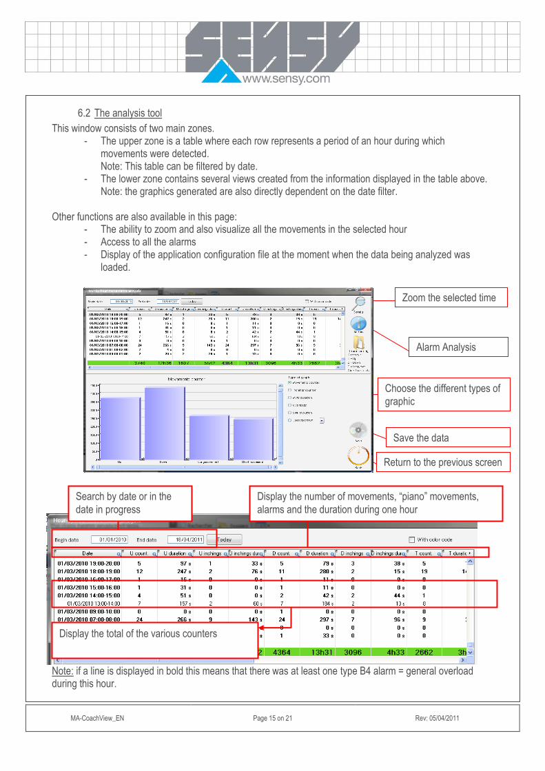
6.2 The analysis tool
This window consists of two main zones. - The upper zone is a table where each row represents a period of an hour during which
movements were detected. Note: This table can be filtered by date.
- The lower zone contains several views created from the information displayed in the table above. Note: the graphics generated are also directly dependent on the date filter.
Other functions are also available in this page:
- The ability to zoom and also visualize all the movements in the selected hour - Access to all the alarms - Display of the application configuration file at the moment when the data being analyzed was
loaded. Note: if a line is displayed in bold this means that there was at least one type B4 alarm = general overload during this hour.
Search by date or in the
date in progress
Display the number of movements, “piano” movements,
alarms and the duration during one hour
Display the total of the various counters
Zoom the selected time
Alarm Analysis
Choose the different types of
graphic
Save the data
Return to the previous screen

MA-CoachView_EN Page 16 on 21 Rev: 05/04/2011
6.2.1 Types of graphics
6.1.1. Movement counters
6.1.2. “Piano” movement counters

MA-CoachView_EN Page 17 on 21 Rev: 05/04/2011
Note: a “piano” movement = 2 consecutive identical movements with a time interval between the 2 movements of less than 2 seconds Note: more detail is given in the Coach manual).
6.1.3. Duration of the movements
Proportional display of the duration of each movement. (up, down, translation, direction)

MA-CoachView_EN Page 18 on 21 Rev: 05/04/2011
6.1.4. Display of the overload number during the time
6.2.1.1 Load spectrum
Graphical display of the load usage of the gantry

MA-CoachView_EN Page 19 on 21 Rev: 05/04/2011
The load levels can be parameterized by clicking on the following arrow:
6.3 Zoom function
It is possible to zoom in on the last 30 days of gantry usage. That means display in detail all the movements it has made. To do this, choose a row (an hour) and double-click it or click on the icon A new window will be displayed with the following parameters:
− The date + time of the movement. − The type of movement (lift, lower, translation, direction). − The peak force + moment of occurrence. − The average of the signal + the total duration of the movement. − The value of the SWP
Note: if there was a „piano‟ movement, the row will be highlighted in blue.

MA-CoachView_EN Page 20 on 21 Rev: 05/04/2011
It is possible to break the movement down further. This function is interesting for a composite movement. To do this, select the movement and double-click it or select the movement and click on the icon
7 HANDLING ALARMS
By clicking on the „Alarms‟ button on the analysis page you can access the following page:

MA-CoachView_EN Page 21 on 21 Rev: 05/04/2011
This contains the list of alarms detected by Coach as well as the actions triggered, sorted in descending date order. The following filters are available:
- Date - Family code ( „système‟, „pont‟, „trace‟ (system, gantry, track) history) - Alarm code
Note: the alarm codes are different according to the family code selected.
Filter by Alarm Code Filter by Family Code Filter by date or a specific period