maine subsurface waste water disposal...
TRANSCRIPT
10 CMR 241 (August 1, 2005)
MAINE SUBSURFACE WASTE WATER DISPOSAL RULES
144 CMR 241
SUMMARY
This rule governs the siting, design, construction and inspection of
subsurface wastewater disposal systems in order to protect the health,
safety and welfare of the citizens of Maine. Approved procedures, design
and siting requirements, materials, methods and administrative polices are
described in detail.
BASIS STATEMENT: These Rules provide minimum State design criteria for subsurface wastewater disposal to assure environmental
sanitation and safety. These Rules are intended to complement municipal planning,
zoning, and land use control.
EFFECTIVE DATE: August 1, 2005
AUTHORITY: Title 22 MRSA §42
Department of Health & Human Services Maine Center for Disease Control and Prevention
Division of Environmental Health 11 State House Station
Augusta, Maine 04333-0011 Telephone (207) 287-5689
Appropriation 014-10A-2426-012-2658
Nondiscrimination Notice In accordance with Title VI of the Civil Rights Act of 1964, as amended by the civil Rights Restoration Act of
1991 (42 U.S.C. 1981, 2000e et seq.) Section 504 of the Rehabilitation Act of 1973, as amended (29 U.S.C. 794), the Age Discrimination Act of 1975, as amended (42 U.S.C. 6101 et seq.), Title II of the Americans with
Disabilities Act of 1990 (42 U.S.C. 12101 et seq.), and Title IX of the Education Amendments of 1972, the Maine Department of Health and Human Services does not discriminate on the basis of sex, color, national origin,
disability or age in admission or access to or treatment or employment in its programs and activities

10 CMR 241 (August 1, 2005)
THIS PAGE INTENTIONALLY LEFT BLANK
10 CMR 241 (August 1, 2005)
TABLE OF CONTENTS
CHAPTER
Chapter 1 Administration and Enforcement
Chapter 2 General Regulations
Chapter 3 Definitions
Chapter 4 Site Evaluation Requirements
Chapter 5 Design Flows
Chapter 6 Disposal Fields
Chapter 7 Disposal System Setbacks
Chapter 8 Disposal Field Construction Techniques
Chapter 9 Septic Tanks Dosing Tanks and Grease Interceptors
Chapter 10 Primitive Disposal Systems, Alternative Toilets, and Separated Laundry Systems
Chapter 11 Engineered Disposal Systems
Chapter 12 Multi-Use Disposal Systems
Chapter 13 Peat Disposal Systems
Chapter 14 Piping
Chapter 15 Wetlands
Chapter 16 Disposal Fields On Very Permeable Sites In The Shoreland Zone of Major Waterbodies/Courses
Chapter 17 Alteration, Replacement, and Expansion of Existing Disposal Systems
Chapter 18 Experimental Technology and Product Registration Requests
Chapter 19 Variances
Chapter 20 Holding Tanks
Chapter 21 Means of Appeal
Chapter 22 Drip Irrigation Disposal
Appendix A Model Holding Tank Ordinance
Appendix B Proprietary Disposal Devices and Septic Tank Filters
Appendix C Memorandum of Agreement
Appendix D Forms
Index
08/01/05
10 CMR 241 (August 1, 2005)
LIST OF TABLES AND ILLUSTRATIONS
TABLE OR ILLUSTRATION TITLE PAGE NUMBER NUMBER 110.2 Municipal and LURC Territories Permit Fee Schedule 1-4 110.3 Department Review Fee Schedule 1-5 400.1 Key to Drainage Classes 4-6 501.1 Design flows for single family dwellings 5-2 501.2 Design flows for other facilities 5-2 603.1 Adjustment factor for wastewater strengths different from typical 6-2 domestic wastewater 604.1 Equation 604.1 6-2 600.1 Soil Profile Soil Condition Design Class 6-4 600.2 Minimum Permitting Conditions and Minimum Design Requirements 6-5 First Time Systems and Major Expansion Systems 600.3 Minimum Permitting Conditions and Minimum Design Requirements 6-6 All Replacement Systems and Expansions Outside the Shoreland Zone
of Major Waterbodies/Courses 600.4 Minimum Permitting Conditions and Minimum Design Requirements 6-7 Expansions within the Shoreland Zone of Major Waterbodies/Courses 700.1 Reduction in setbacks between a single family bedrock well and their 7-1 own first time, less than 1,000 gpd disposal field 700.2 Setback distances for first time systems and/or major 7-3 expansion systems 700.3 Setback distances for replacement systems and/or expansions 7-4 outside the shoreland zone of major waterbodies/courses with plumbing inspector approval 700.4 Setback distances for expansions within the shoreland zone of major 7-5 waterbodies/courses 705.0 Setbacks from coastal Wetlands, Freshwater Wetlands, Great Ponds,
Waterbodies/Courses and other Features 7-6 800.1 Stone Size – Maximum Percent Passing by Weight 8-3 906.1 One to three family dwelling unit septic tank capacity 9-2 14-1 Plumbing Material Standards for disposal systems 14-3 1407.7 Friction loss in schedule 40 plastic pipe 14-7 1407.8 Holding capacity of pipes 14-7 1900.1- Soil, Site and Engineering Factors Used in Assessing Potential for a 19-3 & 1900.11 First Time System Variance 19-4 B-103.2 Sizing for “Bio-Diffuser”, “Infiltrator”, “EnviroChamber”, and B-2 “Contactor” proprietary disposal devices B-104.3 Sizing for “GeoFlow” and Enviro-Septic gravel-less cloth fabric disposal B-2 tubing B-104.4 Sizing for “Eljen In-Drain” gravel-less cloth disposal system B-2 B-109.2 Permitted Substitution of Proprietary Devices B-5
10 CMR 241 (August 1, 2005) Page 1 - 1
CHAPTER 1
ADMINISTRATION AND ENFORCEMENT
SECTION 100.0 GENERAL
100.1 Title: These regulations shall be known as the “Maine Subsurface Wastewater Disposal Rules”, from now on referred to as “this code”. The effective date is August 1, 2005.
100.2 Scope: This code establishes a set of standards, requirements, and procedures to protect public health and the environment from biological and chemical contamination. Such contamination may result if improperly treated wastewater is released either onto the surface of the ground or into the ground water from an on-site collection, storage, or treatment system.
100.3 Interpretation: This code shall be interpreted so as to assure the proper treatment and installation of subsurface systems for the disposal of wastewater.
100.4 Intent: The intent of this code is to ensure public safety, health, and welfare insofar as they are affected by the installation and maintenance of subsurface wastewater disposal systems (from now on referred to as “systems”).
100.5 Wastewater disposal: Any wastewater, as defined in this code shall be disposed of by one of the following methods:
100.5.1 On-site disposal: A subsurface wastewater disposal system designed, installed, and used in accordance with this code;
100.5.2 Public sewer: A public sewer system; or
100.5.3 Licensed discharge: A wastewater discharge system licensed by the Maine Department of Environmental Protection under Title 38 MRSA §413 and §414-A, as amended.
100.6 Public sewer connection: When public sewers come within 200 feet of the premises served, the use of systems shall comply with Title 38 MRSA §1160 or when required under Title 30A, §3405.
100.7 Malfunctioning system: When a malfunctioning system is discovered, the system shall be corrected or its use discontinued within that period of time required by the plumbing inspector’s order.
SECTION 101.0 APPLICABILITY
101.1 General: The provisions of this code shall cover all matters affecting or relating to systems.
101.2 Matters not provided for: There may be subsurface wastewater disposal requirements essential for the sanitation and safety of the occupants thereof that are not specifically covered by this code. Such requirements shall be determined by the Maine Department of Health and Human Services (from now on referred to as the “Department”) with the concurrence of the plumbing inspector.
101.3 Continuation of unlawful use: The continuation of occupancy or use of a structure with a system, or part thereof, contrary to the provisions of this code shall be deemed a violation of this code.
101.4 Referenced standards: Where differences occur between provisions of this code and referenced standards, the provisions of this code shall apply.
101.5 Revocation by Department: The Department may revoke or rescind any written decision it has made, if the decision was made in error. The Department shall only take such action upon demonstration that such decision was based in part or whole upon inaccurate information or false representation(s); or upon determination that the Department failed to follow procedures otherwise required under provisions of these Rules. The Department may also revoke any variance approval upon failure of the owner/applicant to comply with all requirements of the approval.
SECTION 102.0 VALIDITY
102.1 Partial invalidity: In the event any part or provision of this code is held to be illegal or void, this shall not have the effect of making void or illegal any of the other parts or provisions of this code that may or shall be determined to be legal. It shall be presumed that this code would have passed without such illegal or invalid parts or provisions.
102.2 Segregation of invalid provisions: Any invalid part of this code shall be segregated from the remainder of the code by the court holding such part invalid, and the remainder shall remain effective.
102.3 Existing systems: The invalidity of any provision of this code as applied to existing systems shall not be held to affect the validity of such section in its application to systems hereafter built.
SECTION 103.0 EXISTING SYSTEMS 103.1 Conditions of use: The use of any subsurface wastewater disposal system that was in existence and functional prior to July 1, 1974, is allowed provided all of the following conditions are met.
103.1.1 Design flow: The current calculated wastewater design flow is equal to or less than the calculated value prior to July 1, 1974; and
103.1.2 System Status: The system is not currently malfunctioning as defined in Chapter 3, and
103.1.3 System Use: Use of the system has not been discontinued for a period of five years or more.
103.2 Expanded Systems: Any system in existence and functioning prior to July 1, 1974 not in compliance with Section 103.1.1 shall be replaced or enlarged using the criteria for a minor or major expansion; as appropriate; as described in Chapter 17.
ADMINISTRATION AND ENFORCEMENT
Page 1-2 10 CMR 241 ( August 1, 2005)
103.3 Malfunctioning Systems: Any system in existence and functioning prior to July 1, 1974 not in compliance with the conditions of Section 103.1.2 shall be replaced using the criteria for a replacement system as described in Chapter 19.
103.4 Abandoned Systems: Any system in existence and functioning prior to July 1, 1974 not in compliance with the conditions of Section 103.1.3 shall be replaced using the criteria for a replacement system as described in Section 19.
103.5 Replacement structures: A structure is considered to be a replacement structure if: 1) it is used to replace the original structure which was destroyed by fire or natural disaster; or 2) it is exchanged with another structure of similar usage and design flow. A replacement structure may be served by the existing sewage disposal system provided:
103.5.1 System properly functioning: The existing system was functioning properly when use of the system ceased; and
103.5.2 No additional load: The design flow of the replacement structure does not exceed the design flow of the existing system, except as provided for in Section 1702.0.
103.5.3 Outside the Shoreland Zone of major waterbodies/courses: The disposal area is outside the shoreland zone of major waterbodies/courses and the replacement structure is connected to the existing system and the existing system was designed and installed after July 1, 1974. If the replacement structure is connected to the existing system, and the existing system was designed prior to July 1, 1974, a back-up design must be prepared which meets the replacement system criteria and complies with Section 1703.0, or
103.5.4 Inside the Shoreland Zone of major waterbodies/courses: The disposal area is within the shoreland zone of major waterbodies/courses and the replacement structure is connected to the existing system, and the existing system was designed and installed after July 1, 1974. If the replacement structure is connected to the existing system, and the existing system was designed and installed prior to July 1, 1974, a replacement system must be installed, or the existing system must be determined, by a licensed Site Evaluator, to comply with replacement system criteria.
103.6 Structures not considered as replacement structures: Structures that do not meet the requirements of 103.0 must have disposal systems that meet the requirements of a first time system.
SECTION 104.0 REPAIRS AND MAINTENANCE
104.1 Disposal system permit not required: A disposal system permit is not required for minor repairs or replacements made as needed for the operation of pumps, siphons or accessory equipment, the clearance of a stoppage, or sealing of a leak in the septic tank, holding tank, pump tank, or building sewer.
104.2 Disposal field modification, repair or alteration: Any modification, repair or alteration of the disposal field, other than the addition of fill requires the decision of the Local Plumbing Inspector as to whether or not a permit is required. If a permit is required, such modification, repair or alteration shall be as prescribed by a Maine Registered Professional Engineer or a Maine Licensed Site Evaluator and shall be considered a disposal field for permitting purposes.
104.3 Maintenance: All new and existing systems shall be maintained in a safe and sanitary condition. All service equipment, devices, and safeguards required by this code, or that were required for a system by previous subsurface wastewater disposal codes, shall be maintained in good working order when installed, altered, or repaired.
104.4 Property owner’s responsibility: The property owner or property owner’s agent shall be responsible for the safe and sanitary maintenance of the system at all times.
SECTION 105.0 APPROVAL
105.1 Approved materials and equipment: All materials, equipment, and devices approved for use by the Department shall be made and installed in accordance with the conditions of approval.
105.2 Modifications: When there are practical difficulties involved in carrying out the provisions of this code, the Department may vary or modify such provisions upon a variance request by the applicant. Variances may be granted provided that the intent of this code is observed and public health, safety, and welfare are assured. The variance request for modifications and the final decision of the plumbing inspector or the Department shall be in writing and officially recorded with the variance application in the permanent records of the jurisdiction. See Chapter 19.
105.3 Used materials and equipment: Used materials, equipment, and devices may be used provided that they have been reconditioned, tested, and placed in good and proper working condition. Such use shall be approved in advance by the plumbing inspector. Septic tanks in place and in good condition, and adequately sized may continue in use when a disposal field is replaced.
105.4 Alternative materials and equipment: The provisions of this code are not intended to prevent the use of any material, equipment, or method not specifically prescribed by this code provided the use of any such alternative device has been approved in advance. The Department may approve any such alternative, provided the Department finds that the proposed material, equipment, or method is satisfactory and complies with the intent of the provisions of this code. In addition, it shall be shown that the material, equipment, method, or work offered is, for the purpose intended, at least the equivalent of that prescribed in this code in quality, strength, effectiveness, durability, and safety. The Department shall require sufficient technical data to be submitted to substantiate the proposed use of any material or method. If it is determined that the
ADMINISTRATION AND ENFORCEMENT
10 CMR 241 (August 1, 2005) Page 1-3
evidence submitted is satisfactory proof of performance for the use intended, its use may be approved, subject to the requirements of this code. The costs of all tests, reports and investigations required under these provisions shall be paid by the applicant. To assist in the determination, the Department may accept as supporting data any duly authenticated research reports from approved sources concerning all materials or devices proposed for uses not specifically provided for in this code.
105.5 Prohibition of alternative materials and equipment: The Department may prohibit the use of certain materials, equipment, or methods not specifically prescribed by this code, in the event that the materials, equipment, or methods have not been approved for use by the Department. The Department shall issue any such prohibitions in writing, and shall specify the reason(s) for prohibition of use. Reasons for prohibition of use of certain materials, equipment, or methods may include, but are not limited to, a reasonable expectation that such use would present a threat to public safety, health, and welfare insofar as they are affected by the installation, use, alteration, and/or maintenance of subsurface wastewater disposal systems.
SECTION 106.0 DUTIES AND POWERS OF PLUMBING INSPECTOR
106.1 General: The plumbing inspector shall enforce all the provisions of this code. He or she shall act on any question concerning the method or manner of construction and the materials to be used in the installation of a system, except as may be specifically provided for by other requirements of this code.
106.2 Application for disposal system permits: The plumbing inspector shall receive applications for disposal system permits, issue permits for the installation of systems, inspect the premises for which such disposal system permits have been issued, and enforce compliance with the provisions of this code.
106.3 Notices and orders: The plumbing inspector shall issue all necessary notices or orders pertaining to removal of illegal or unsafe conditions, the requirement of necessary safeguards during construction, and compliance with all requirements of this code for the safety, health, and general welfare of the public.
106.4 Inspections: The plumbing inspector shall make all the inspections required in this code. The plumbing inspector may engage such expert opinions as may be deemed necessary to report upon unusual technical issues that may arise, subject to the approval of the municipal officers.
106.5 Credentials: The plumbing inspector shall carry proper credentials of the office while inspecting any and all systems and premises in the performance of his or her duties.
106.6 Annual report: At least annually, the plumbing inspector shall submit to the municipal officers of the jurisdiction a written statement of code enforcement
activities in form and content as shall be prescribed by such authority.
SECTION 107.0 APPLICATION FOR DISPOSAL SYSTEM PERMIT
107.1 Disposal system permit required: Work shall not be started until the plumbing inspector has issued a disposal system permit for the work. Installing a new, expanded, or replacement subsurface wastewater disposal system or any individual components requires a permit except those activities specified in Section 104.0.
107.2 Application for disposal system permit form: An application for a disposal system permit shall be made on forms provided or approved by the Department. Permit applications shall be prepared by a licensed site evaluator and requires a site evaluation with the exception of replacement septic tanks and alternative toilets other than pit privies. Such application shall include an adequate description of the proposed work. See Section 401.0.
107.3 Description of work: The application for a disposal system permit shall contain a description of the type of system, its location, the use of the structure for which the system is requested, and such additional information as may be required by Chapter 4 or by a municipal ordinance.
107.4 Amendments: Amendments to a subsurface wastewater disposal system permit, application for a permit, or any accompanying records may be made at any time before work on the system is complete. Such amendments are deemed part of the original application for the disposal system permit and shall be filed therewith.
107.5 Previous designs: A revision in this code shall not require changes in a subsurface wastewater design provided a permit is obtained for the subsurface wastewater disposal system within two years of the date the disposal system design was signed by the Site Evaluator who completed the design. A design more than two years old and not permitted shall be reviewed and updated as necessary by the Site Evaluator prior to the issuance of a permit.
SECTION 108.0 SUBSURFACE DISPOSAL SYSTEM PERMITS
108.1 Action on application for subsurface disposal system permit: The plumbing inspector shall examine, or cause to be examined, all applications for disposal system permits, and amendments thereto after a completed filing. If the application for a disposal system permit does not conform to the requirements of this code (except as allowed by 107.5), and all pertinent laws, ordinances and regulations, including those administered by public water system, or if it is considered incomplete, such application for a disposal system permit shall be rejected in writing, stating the reasons therefor. If the plumbing inspector is satisfied that the proposed work
ADMINISTRATION AND ENFORCEMENT
Page 1-4 10 CMR 241 ( August 1, 2005)
conforms to the requirements of this code and all applicable laws, ordinances, and regulations, including those administered by public water supplies, a disposal system permit shall be issued as soon as practicable.
108.2 Nontransferable: A disposal system permit shall not be transferable.
108.3 Previous approvals: A revision in this code shall not require changes in a disposal system for which a permit has been issued or otherwise lawfully authorized, prior to the effective date of this code.
108.4 Signature on disposal system permit: The plumbing inspector’s signature shall be affixed to every disposal system permit.
108.5 Revocation: The plumbing inspector shall revoke a disposal system permit or approval issued under the provisions of this code in the case of any false statement(s) or misrepresentation(s) of fact in the application for the disposal system permit or on the plans on which the disposal system permit or approval was based.
108.6 Time limit: Any disposal system permit issued shall become invalid if the authorized work has not been completed within two years after the issue date of the disposal system permit, unless granted an extension by the local plumbing inspector.
108.7 Departures from the design: Departures from the approved design that become necessary due to circumstances arising during construction and installation shall be approved by the site evaluator and/or professional engineer and the plumbing inspector. Such changes shall meet or exceed the minimum requirements of this code.
SECTION 109.0 REQUIREMENTS OF DISPOSAL SYSTEM PERMIT
109.1 Payment of fees: A disposal system permit shall not be issued until the fee prescribed in Section 110.0 has been paid.
109.2 Compliance with this code: The disposal system permit shall be a license to proceed with work and shall not be construed as authority to violate, cancel, or set aside any of the provisions of this code, except as specifically stipulated by modification or legally granted variance as described in the application for disposal system permit.
109.3 Compliance with disposal system permit: All work shall conform to the plans as shown on the application for which a disposal system permit is issued. This includes any approved amendments thereto.
SECTION 110.0 FEES
110.1 General: A disposal system permit to begin work for new construction or alteration shall not be issued until the prescribed disposal system permit fee has been paid.
110.2 Fee schedule: Minimum disposal system permit fees, assessed by municipalities, are listed in Table 110.2. Pursuant to Maine law, municipalities retain 75% of those minimum permit fees and must forward the
remaining 25% to the Department. Review fees, assessed by the Department, are listed in Table 110.3. Note: Municipalities may assess additional permit fees, above those listed in Table 110.2, if authorized to do so by local ordinance. The entire additional permit fees are retained by the municipality.
TABLE 110.2 MUNICIPAL AND LURC TERRITORIES PERMIT FEE
SCHEDULE (Fees to be paid to the municipality/LPI) Permits for complete disposal system
Engineered system $200.00 Non-engineered system $100.00 Primitive system (includes one alternative toilet) $100.00 Separate laundry disposal field $35.00 Seasonal conversion permit $50.00 Variance $20.00
Permits for separate parts of disposal system
Alternative toilet (only) $50.00 Disposal field (engineered system) $150.00 Disposal field (non-engineered system) $75.00 Treatment tank (non-engineered system) $50.00 Treatment tank (engineered system) $80.00 Holding tank $100.00 Other components (complete pump station, piping, other)
$30.00�
Variance $20.00
110.2.1 Late permit fee: A person who starts construction without first obtaining a disposal system permit shall pay double the permit fee indicated in Table 110.2.
110.2.2 Additional inspection fee: Inspections and fees, in addition to those mandated by these Rules, may be required by the LPI, through adoption of a local ordinance. Additional inspections may also be required by the LPI when work is found to be incomplete at a prearranged inspection, when work is found to be unsatisfactory or when access cannot be obtained at a prearranged date and time. In such cases, additional inspection fees may be assessed by the municipality with the entire additional fees being retained by the municipalities.
TABLE 110.3 DEPARTMENT REVIEW FEE SCHEDULE (Fees to be paid directly to the Department)
Engineered system review - Chapter 11 $100.00 Formal Conference Fee - Chapter 21 $50.00 Formal Administrative Hearing Fee - Chapter 21 $75.00 Minimum lot request review fee $50.00 Multi-user review fee - Chapter 12 $100.00 Licensed Establishment Review $20.00 Microfilm Record Search $15.00
SECTION 111.0 INSPECTIONS
111.1 Required: It shall be the duty of the plumbing inspector to enforce the provisions of this code and to make such inspections as may be required by this Section.
ADMINISTRATION AND ENFORCEMENT
10 CMR 241 (August 1, 2005) Page 1-5
111.2 Required inspections: Any violations of the approved plans and disposal system permit shall be noted. The holder of the disposal system permit shall be notified of any such discrepancies.
111.3 Plumbing inspector’s right of entry: In the discharge of duties, the plumbing inspector, with the consent of the property owner, occupant, or owner’s agent, shall have the authority to enter at any reasonable hour any structure or premises in the jurisdiction to enforce the provisions of this code. Reference 30-A MRSA §4213. If entry is refused the LPI can seek a court order for entry.
111.4 Department official’s right of entry: In the discharge of duties, Department officials, with the consent of the property owner, occupant, or owner’s agent, shall have the authority to enter at any reasonable hour any structure or premises to enforce the provisions of this code. If entry is refused the Department can seek a court order for entry.
111.5 Inspection required: The LPI shall make two inspections as follows:
111.5.1 After site preparation: An inspection shall be made after site preparation to ascertain that the vegetation has been cut and removed in the disposal field area, the area under the disposal field and backfill extensions has been roughened, a transitional horizon has been established, and the erosion and sedimentation control measures are in place.
111.5.2 Prior to covering the system: An inspection shall be made after installation of the system components, including stone, pipes or proprietary devices, tanks, hay, filter fabric, and fill beneath and beside of the disposal area but before backfill is placed above the disposal system components. This inspection shall include any curtain drains, diversion ditches, berms or other measures outlined on the design to improve the function of the system; and
111.6 Notification required: The plumbing inspector shall be notified at least 24 hours before the system is ready to be inspected.
111.7 Preparation for inspection: When a system is ready for inspection, the installer shall make such arrangements as will enable the plumbing inspector to inspect all parts of the system. The installer shall have present the proper apparatus and equipment for conducting the inspection and shall furnish such assistance as may be necessary in making a proper inspection.
111.8 Covering of work: No part of a system may be backfilled until it has been inspected and approved. If any part is covered before being inspected and approved, it shall be uncovered at the discretion of the plumbing inspector and at the expense and risk of the owner.
111.9 Defects in materials and workmanship: If inspection discloses defective material, design, siting, or poor construction that does not conform to the
requirements of this code, the nonconforming parts shall be removed, replaced, and reinspected.
111.10 Installer’s statement of compliance: The State shall provide a form (HHE-238A) for the LPI to be given to the homeowner, or the homeowner’s agent, at the time of issuing the permit. This form will allow for the installer or inspector, in the case of an engineered system or a multi-user system, to provide a written statement to the owner, or agent, that the system was installed in compliance with this code and the conditions of the permit.
SECTION 112.0 WORKMANSHIP
112.1 General: All work shall be performed, installed, and completed in a workmanlike and acceptable manner commensurate with the specific requirements of this code, or generally accepted practices if not specifically addressed by this code, and the standards referenced herein.
SECTION 113.0 VIOLATIONS
113.1 Unlawful acts: It shall be unlawful to install, extend, alter, repair, or maintain systems except in conformity with this code.
113.2 Notice of violation: The plumbing inspector shall serve a notice of violation and order on the person responsible for the installation of work: in violation of the provisions of this code; in violation of a detailed statement or a plan approved thereunder; or in violation of a disposal system permit or certificate issued under the provisions of this code. Such orders shall direct the discontinuance of the illegal action or condition and the abatement of the violation.
113.3 Prosecution: If the notice of violation and order are not complied with promptly, the plumbing inspector shall request the legal counsel of the jurisdiction to institute the appropriate proceedings at law or in equity to restrain, correct, or abate such violation, or to require removal or termination of the unlawful use of any system in violation of the provisions of this code or of the order or direction made pursuant thereto.
113.4 Penalties: Any person who shall violate a provision of this code, or who shall fail to comply with any of the requirements thereof, or who shall install work in violation of an approved plan or directive of the plumbing inspector, or of a disposal system permit issued under the provisions of this code, shall be subject to the penalties in Title 30-A MRSA §4452.
SECTION 114.0 STOP WORK ORDER
114.1 Stop work order notice: Upon notice from the plumbing inspector that work is being done contrary to the provisions of this code, such work shall be immediately stopped. The stop work order shall be in writing and shall be given to the owner of the property involved, or to the property owner’s agent, or to the person doing the work. It shall state the conditions under which the work may be resumed.
114.2 Unlawful continuance: Any person who shall continue any work after having been served with a stop
ADMINISTRATION AND ENFORCEMENT
Page 1-6 10 CMR 241 ( August 1, 2005)
work order, except such work as the person is directed to perform to remove a violation or unsafe condition, shall be considered in violation of this code.
SECTION 115.0 CERTIFICATE OF APPROVAL
115.1 Approval: After the required inspection, or, in the case of multiple inspections, when the final inspection indicates the work complies in all respects with this code and the permit application, a certificate of approval shall be issued by the plumbing inspector.
115.2 Thirty (30) day temporary use: Upon request of the holder of a disposal system permit, the plumbing inspector may issue a 30 day temporary authorization of use before the entire work covered by the disposal system permit shall have been completed. This authorization may be given only if such portion or portions of the system may be put into service safely prior to full completion without endangering health or public welfare.
SECTION 116.0 UNSAFE CONDITIONS
116.1 General: All installations, regardless of type, that are unsanitary or that constitute a hazard to human life, health, or welfare are hereby declared a nuisance and shall be abated by repair and rehabilitation or removal.
116.2 Structures: No portion of a structure shall be located on any part of a disposal field.
SECTION 117.0 MUNICIPAL RECORDS
117.1 Required: The municipality shall keep official records of applications for disposal system permits received, disposal system permits and certificates issued, fees collected, reports of inspections, and notices and orders issued.
117.2 Record retention: The disposal system permit and associated records shall be maintained until such time as the realty improvement served by the proposed or existing system is removed or connected to a public sewer.
117.3 Record availability: These records shall be available upon request for inspection by personnel of the Department and the public.
117.4 Associated records: The municipality shall also maintain and keep on file copies of the following documents:
117.4.1 Applications: Applications for disposal system permits and plans and specifications for the construction, installation or alteration of systems, including all forms and data submitted by the applicant;
117.4.2 Modifications: Modifications to plans or applications made subsequent to the issuance of a disposal system permit to construct, install, or alter systems;
117.4.3 Inspections: Reports of construction inspections made prior to issuance of a certificate of approval for a system;
117.4.4 Certificates of approval (HHE-238): Certificates of approval completed for inspections of systems; and
117.4.5 Malfunctioning systems: Inspection reports, plans, and specifications for repair or alteration of malfunctioning systems or components of malfunctioning systems.
SECTION 118.0 LOCAL ORDINANCE
118.1 General: The municipality may adopt local ordinances as allowed by MRSA Title 30-A §4211.
118.2 Definition: For the purpose of this code, the term “local ordinance” means any municipal ordinance that is more restrictive than any provision in these Rules.
118.3 No less stringent: The municipality shall not adopt an ordinance that is less stringent than this code.
118.4 Notification: In order for the Department to keep track of local requirements that may differ from the minimum requirements contained herein, any municipality that adopts a local ordinance is requested to send a copy of the ordinance to the Department.
SECTION 119.0 APPROVED SYSTEM USAGE
119.1 General: No system may be used nor shall any wastewater be directed to any components/system until a certificate of approval has been issued or the plumbing inspector has issued a temporary authorization of use in compliance with Subsection 115.2 of this code.
SECTION 120.0 UNORGANIZED AREAS
120.1 Scope: This Section governs the appointment of plumbing inspectors and the administration of this code in unorganized portions of the State of Maine where there is no local form of government.
120.2 Plumbing inspector appointment: The Department may appoint plumbing inspectors in the unorganized areas. The appointed plumbing inspector is responsible for performing all the administrative and enforcement duties prescribed in this Chapter.
120.3 Lack of plumbing inspector: If a plumbing inspector has not been appointed, the following procedure shall be utilized:
120.3.1 Permit issuance: The Department is responsible for performing all the administrative and enforcement duties prescribed in Section 106.0.
120.3.2 Installer’s statement of compliance: The State shall provide a form (HHE-238A) for the Site Evaluator to give to the homeowner, or the homeowner’s agent, at the time of the site evaluation. The form will allow the installer or inspector, in the case of an engineered system or a multi-user system, to provide a written statement to the owner, or agent, that the system was installed in compliance with this code and the conditions of the permit. This form will then be sent to the Department.
ADMINISTRATION AND ENFORCEMENT
10 CMR 241 (August 1, 2005) Page 1-7
SECTION 121.0 ADVISORY RULING
121.1 Written request: Upon written request the Department may render an advisory ruling with respect to the interpretation and/or applicability of any subsurface wastewater disposal related statute or rule administered by the Department.
121.2 Request address: A request for an advisory ruling shall be addressed to the Director, Division of Environmental Health, Department of Health and Human Services, 11 State House Station, Augusta, Maine 04333-0011.
121.3 Contents of request: The request for an advisory ruling shall contain sufficient facts for the Department to make a ruling. The Department may request additional information from the party requesting the ruling. Failure to provide such information shall be cause for the Department to refuse to issue a ruling.
121.4 Refusal to issue ruling: The Department may refuse to issue an advisory ruling if it may harm its interest in any litigation to which it is or may become a party.
121.5 Response time: An advisory ruling shall be in writing and issued no more than sixty (60) days from the date when all information necessary for the ruling has been received by the Department.
121.6 Verbal opinions: Verbal opinions do not carry the weight of advisory rulings. They are the opinion of Department staff, without benefit of legal consultation. Verbal opinions may be reversed when presented to the Department as written requests for Advisory Rulings.

ADMINISTRATION AND ENFORCEMENT
Page 1-8 10 CMR 241 ( August 1, 2005)
10 CMR 241 ( August 1, 2005) Page 2-1
CHAPTER 2
GENERAL REGULATIONS
SECTION 200.0 GENERAL
200.1 Scope: This Chapter governs the general regulation of all systems.
SECTION 201.0 AUTHORIZED DESIGNERS
201.1 Non-engineered systems: A site evaluator licensed in Maine shall design non-engineered systems.
201.2 Engineered systems: A site evaluator licensed in Maine shall provide observation hole logs and soil profile descriptions as described in Section 403.0 for engineered systems. A professional engineer, licensed in Maine, shall design engineered systems, and may consult with the site evaluator.
SECTION 202.0 DESIGN REQUIREMENTS
202.1 All systems: In designing any system, the site evaluator and/or professional engineer shall take into consideration lot size and configuration, slope, surface drainage, soil characteristics, the presence and depth of limiting horizons within the soil, soil permeability, type of wastes, and the projected design flow.
202.2 Types of wastes: Systems shall be designed to receive all wastewater from the structure served except in the following cases:
202.2.1 Black or gray wastewaters only: Separate systems may be designed to receive only gray wastewater, or only black wastewater, as allowed in Chapter 10.
202.2.2 Laundry wastes: Laundry wastes from a single-family dwelling may be discharged into a separate laundry disposal field. See Section 1008.0.
202.2.3 Hot tubs: Hot tubs shall not discharge into any disposal system utilized for any other wastewater, but may be discharged into a separate laundry disposal field.
SECTION 203.0 DEPARTMENT OF ENVIRONMENTAL PROTECTION
203.1 License Not Required: In accordance with Title 38, MRSA §413, a waste discharge license shall not be required for the installation, operation or maintenance of a subsurface wastewater disposal system for the subsurface disposal of domestic wastewater or other wastewater from commercial, industrial, or residential sources which is of a similar quality (constituents and strength) to that of domestic wastewater provided it has been designed and installed in conformance with this code. This includes, but is not limited to, wastewater normally associated with hospitals, restaurants, nursing homes, schools, hotels, motels, and medical, dental and veterinary facilities.
203.2 License Required: In accordance with Title 38, MRSA §413, a waste discharge license shall be required
for the installation, operation or maintenance of a subsurface wastewater disposal system for the subsurface disposal of wastewater from commercial, industrial, or residential sources which has constituents unlike that of or is significantly higher strength than that of domestic wastewater and is therefore beyond the jurisdiction of this code. This includes, but is not limited to, wastewater normally associated with abattoirs, commercial car washes, egg washing facilities, and industrial processes.
SECTION 204.0 PROHIBITED
204.1 Discharging prohibited: The use of system cleaners that contain restricted chemical materials is deemed a discharge of industrial wastes and is prohibited. See Section 910.0.
204.2 Chemicals: Chemicals, other than normal household cleaners, shall not be disposed of in the disposal field. Examples of prohibited chemicals include paint, paint thinner, commercial grease and oil, darkroom chemicals, etc.
SECTION 205.0 ROOF, FLOOR, AND FOUNDATION DRAINS
205.1 General: Discharges from roof drains, floor drains, and foundation drains may adversely affect a system because of their potential volumes and different pollutant characteristics.
205.2 Roof drains and foundation drains: Roof drains and foundation drains shall not be connected to systems.
205.3 Floor drains: Floor drains may be connected to a subsurface wastewater disposal system if (1) the disposal area is properly sized to handle the potential flow from the drains (2) there is no significant potential for discharge of industrial, hazardous, or toxic liquids; (3) the floor drain is necessary for the discharge of wash water or other wastewater which has constituents similar in volume or concentration to domestic wastewater (including animal or vegetable matter, soap solutions, and diluted domestic-use cleaning solutions); and (4) connection to a public sewer is not available. Floor drains shall not be connected to a subsurface wastewater disposal system if there is a significant potential for industrial, hazardous or toxic liquids (including gasoline, oils and degreasers) to drip, be spilled or washed into the floor drains.
SECTION 206.0 LARGE CAPACITY CESSPOOLS
206.1 Prohibition: All existing large capacity cesspools must be closed by April 5, 2005. New large capacity cesspools are prohibited.
GENERAL REGULATIONS
Page 2-2 10 CMR 241 ( August 1, 2005)
206.2 Pre-closure Notification: Thirty (30) days prior to closing a large capacity cesspool, the owner or operator must notify the Department of Environmental Protection of his/her intent to close the cesspool. A copy of this notice shall be forwarded to the Department of Health and Human Services.
206.3 Closure: A large capacity cesspool must be closed in a manner that prevents movement of contaminated fluid to ground water. The owner or operator must also dispose or otherwise manage any soil, gravel, sludge, liquids or other materials removed from or adjacent to the cesspool in accordance with all applicable Federal, State and Local regulations.
SECTION 207.0 LICENSED ESTABLISHMENTS
207.1 Applicability: This section applies to all establishments licensed by the Department of Health and Human Services utilizing subsurface wastewater disposal.
207.2 Department review required: The local plumbing inspector shall not issue a permit for a new, expanded, or replacement system serving a licensed establishment without prior approval from the Department.
207.3 Conditions requiring review: The following changes to a licensed establishment’s status require a review of the subsurface wastewater disposal system by the Department:
207.3.1 The planned installation of a new, expanded, or replacement system; or
207.3.2 A planned increase in the licensed establishment’s capacity.
207.4 Review Submission: The owner of the establishment shall submit the following items to satisfy the requirements of Section 207.3.
207.4.1 A clear description of the past, present, and intended future use of the establishment; and;
207.4.2 A description of any existing subsurface wastewater disposal systems proposed for use; and;
207.4.3 A copy of the HHE-200 form for any new, expanded, or replacement systems; and
207.4.4 The review fee listed in Table 110.3 of these rules.
10 CMR 241 ( August 1, 2005) Page 3-1
CHAPTER 3
DEFINITIONS
SECTION 300.0 GENERAL
300.1 Scope: Unless otherwise expressly stated, the following terms shall, for the purpose of this code, have the meanings set forth in the following Sections.
300.2 Interchangeability: Words used in the present tense include the future tense; words in the masculine gender include the feminine and neuter; the singular number includes the plural, and the plural includes the singular.
300.3 Terms defined in other codes: Terms not defined in the following Sections shall have ascribed to them their ordinarily accepted meanings such as the context may imply.
300.4 Terms not defined: Terms not defined in the following Sections shall have ascribed to them their ordinarily accepted meanings such as the context may imply.
SECTION 301.0 GENERAL DEFINITIONS
Abutter: One that abuts; specifically, the owner of contiguous property. For purposes of the Subsurface Wastewater Rules, “abutter” is further defined to include that property, which is separated by a right of way and/or within setback requirements between a subsurface wastewater disposal field and a potable water supply; whichever was installed first.
Adjacent wetlands: See work adjacent to wetlands and waterbodies/courses. This is a term applied to soil disturbance activities when located such that sediment from the activity may carry into the wetland or water body; generally a distance of 100 feet. (See Section 1504.0).
Aerobic: A condition in which molecular oxygen is a part of the environment.
Alteration: Any change in the physical configuration of an existing system or any of its component parts. This includes the replacement, modification, installation, addition, or removal of system components, or increase in size, capacity, type, or number of one or more components. The term “alter” shall be construed accordingly.
Alternative toilet: A device, other than a water closet, designed to treat human waste only. Examples are: privies and composting, chemical, recirculating, incinerating, and vacuum toilets. Portable toilets are not considered Alternative Toilets as they are only for temporary use (see definition of temporary portable toilet).
Anaerobic: A condition in which molecular oxygen is absent from the environment.
Applicant: The person who signs and submits an application for permit to construct, install, or alter a system.
Application for disposal system permit: Abbreviation for subsurface wastewater disposal system permit application, also known as HHE-200 form, HHE-234, etc.
Backfill: Soil material that is suitable for use beneath and beside of the disposal field, including the fill extension. See Section 804.0.
Bedrock: A solid and continuous body of rock, with or without fracture, or a weathered or broken body of rock fragments overlying a solid body of rock.
Bedroom: Any room within a dwelling unit that serves primarily as sleeping quarters.
Black wastewater: Wastewater derived from plumbing fixtures or drains that receive excreta supplemented wastewater.
Building drain: That part of the lowest horizontal piping of a drainage system that receives the discharge from soil, waste, and other drainage pipes inside the walls of a building and conveys it to the building sewer. Inside the building, it is considered to be the building drain until it undergoes a change of pitch more than that produced by a 45 degree wye. It extends to a point 8 feet outside the building wall.
Building sewer: That part of the plumbing system that extends from the end of the building drain and conveys its discharge to a public sewer, septic tank and disposal field, or other point of disposal.
Bunkhouse: A detached bedroom having no plumbing; accessory to a single family dwelling for the temporary accommodations of guests of the property owner while the owner is an occupant of the principal dwelling.
Certificate of approval: A certificate signed by the plumbing inspector stating that a system has been installed in compliance with the disposal system permit application and this code.
Cesspool, large capacity: A cesspool that receives solely domestic wastewater and has the capacity to serve 20 or more persons per day or dispose of 2,000 gallons or more of wastewater per day. This definition includes multiple-dwelling, community or regional cesspools but does not apply to single-family residential cesspools.
Clay: A particle size category consisting of mineral particles that are smaller than 0.002 millimeters in equivalent spherical diameter; also, a soil texture class having more than 40% clay, less than 45% sand, and less than 40% silt.
CMR: Abbreviation for Code of Maine Rules. For example, 10-144 CMR 241.9 identifies Section 9 of Chapter 241 of the Rules of the Maine Center for Disease Control and Prevention within the Department of Health and Human Services, Maine Subsurface Wastewater Disposal Rules.
DEFINITIONS
Page 3-2 10 CMR 241 ( August 1, 2005)
Coastal sand dune: Sand deposit within a marine beach system above high tide including, but not limited to: beach berm, frontal dune ridge, back dune area, and other sand areas deposited by wave or wind action.
Code: Code means the “Maine Subsurface Wastewater Disposal Rules”.
Construct: To build, install, fabricate, or put together on a site one or more components of a system.
Contour: An imaginary line of constant elevation on the ground surface. The corresponding line on a map is called a “contour line”.
Curtain drain: A trench to intercept laterally moving ground water and divert it away from a disposal field.
Department: The Maine Department of Health and Human Services.
Design flow: The wastewater flow that may reasonably be expected to be discharged from a residential, commercial, or institutional facility on any day of operation as determined in Chapter 5.
Disposal field: An individual subsurface wastewater disposal system component, consisting of a closed excavation made within soil or fill material to contain disposal field stone in which distribution pipes or approved proprietary devices have been placed for the disposal of septic tank effluent.
Disposal field, peat: A disposal field utilizing peat that is designed and installed in accordance with Chapter 13.
Disposal field, primitive: See definition, “Primitive disposal field”.
Disposal field, separated laundry: See definition, “Separated laundry disposal field”.
Disposal field stone: Gravel or crushed stone, that is clean and free of dust, ashes or clay, and meeting the requirements prescribed in the Subsection 805.2.3.
Disposal field infiltration area: The total disposal field infiltration area available to accept the septic tank effluent. The infiltration area includes the bottom and side wall below the invert of the distribution piping.
Disposal field infiltration area, effective: The standard stone filled disposal field infiltration area or the equivalent various “approved” proprietary disposal devices.
Disposal system: See definition, “Subsurface wastewater disposal system”.
Disposal system permit: Written authorization issued by the plumbing inspector to construct a specific system. This authorization is attached to the application for disposal system permit.
Distribution box: A device that receives septic tank effluent and distributes such effluent in equal portions to two or more disposal fields or distribution pipes within a disposal field.
Distribution pipe: A perforated pipe or one of several perforated pipes used to carry and distribute septic tank effluent throughout the disposal field.
Distribution network: Two or more interconnected distribution pipes.
Diversion box: A device that permits alternating use of two or more disposal fields or the diversion of septic tank effluent.
Diversion ditch: A ditch to intercept and divert surface water runoff around and away from a subsurface wastewater disposal system.
Domestic wastewater: Any wastewater produced by ordinary living uses, including liquid waste containing animal or vegetable matter in suspension or solution, or the water-carried waste from the discharge of water closets, laundry tubs, washing machines, sinks, dishwashers, or other source of water-carried wastes of human origin.
Dosing tank: A watertight receptacle located between the septic tank and disposal field equipped with a pump or siphon, used to store and deliver doses of septic tank effluent to the disposal field.
Drainage area: An area from which the surface runoff is carried away by a single watercourse.
Drainage ditch: A manmade ditch receiving and diverting surface runoff or subsurface water. This does not include diversion of a naturally occurring water body.
Drop box: A wastewater distribution device where the elevation of the incoming distribution line is higher than that of the outgoing distribution line.
Drop manhole: A manhole installed in a sewer where the elevation of the incoming sewer is considerably above that of the outgoing sewer.
Dwelling unit: Any structure or portion of a structure, permanent or temporary in nature, used or proposed to be used as a residence seasonally or throughout the year.
Effluent line (gravity): The pipe(s) used to convey septic tank effluent from the tank to the disposal field(s), including non-perforated pipes going from a distribution box or other flow splitting device to a disposal field or multiple disposal fields.
Elevation reference point: An easily-identifiable point or object of constant elevation for establishing the relative elevation of observation holes and elevation of the components of the system.
Engineer: See Professional Engineer.
Engineered system: See System, Engineered.
Equivalent spherical diameter: The equivalent spherical diameter of a particle is the diameter of a sphere that has a volume equal to the volume of the particle.
Expansion: The enlargement or change in use of a structure using an existing subsurface wastewater disposal system that brings the total structure into a classification that requires larger subsurface wastewater disposal system components. (See Chapter 17, Section 1702).
DEFINITIONS
10 CMR 241 ( August 1, 2005) Page 3-3
Expansion, minor: The initial expansion of a single family home after May 1, 1995 by the addition of no more than one bedroom, or if the home is served by pressurized water, the replacement of an alternative toilet by a conventional water closet. For other structures, the initial expansion since May 1, 1995 which results in an increase in design flow of 10 percent or more up to 25 percent.
Expansion, major: Any expansion which results in a greater design flow and larger disposal system components than allowed for minor expansions, the introduction of pressurized water to a structure formerly served by hand pumped or hand carried water, the addition of a second dwelling unit to the property, any second or subsequent minor expansion of a structure since May 1, 1995, or an expansion for a nonresidential use or structure resulting in an increase of more than 25 percent of the existing design flow.
Experimental system: See “System, Experimental”
Fill material: Any soil, rock, or other material placed within an excavation or over the surface of the ground. The term “fill” is not equivalent in meaning to the term “backfill”.
Finish grade: The surface of the ground after completion of final grading.
Flood plain, coastal and estuary: The land area within the V-Zone indicated by the Federal Insurance Rate Maps (FIRM) or below the 10-year storm surge elevation, whichever is more restrictive. The 10-year storm surge elevation in Maine is approximately the 8-foot National Geodetic Vertical Datum.
Flood plain, riverine: The land area within the 10-year flood zone indicated by Soil Conservation Service Soil Maps or other sources acceptable to the Department in the absence of Soil Conservation Service Maps. Note: Some municipalities restrict new development in the 100-year flood plain.
Gpd: Gallons per day.
Gravel: A rounded or semi-rounded rock fragment that is between 2 millimeters and 3 inches in diameter.
Gray wastewater: That portion of the wastewater generated within a residential, commercial, or institutional facility that does not include discharges from water closets and urinals.
Grease interceptor: A device in which the grease in wastewater leaving a structure is intercepted, congealed by cooling, accumulated, and stored for pump-out and disposal.
Grease trap: A device designed to retain grease from a single plumbing fixture.
Great pond: Any inland body of water that, in a natural state, has a surface area in excess of ten acres and any inland body of water artificially formed or increased that has a surface area in excess of 30 acres.
Ground water: Water below the land surface in a zone of soil saturation.
Ground water aquifer: A rock or gravel formation that contains significant recoverable quantities of water that is likely to provide drinking water supplies.
Ground water table: The upper surface of a zone of saturation.
H-20 wheel load: A wheel loading configuration as defined by the American Association of State Highway Officials for a standardized 10-ton-per-axle truck.
Hazardous waste: Any chemical substance or material, whether gas, solid, or liquid, that is designated as hazardous by the U.S. Environmental Protection Agency pursuant to the United States Resource Recovery and Conservation Act, Public Law 94-580.
HHE-200: Subsurface Wastewater Disposal System Application. A three-page form used by Licensed Site Evaluators for designing septic systems.
HHE-204: Replacement System Variance Request. This form is to be attached to an HHE-200 for all replacement systems requiring a variance.
HHE-215: First Time System Variance Request. This form is to be attached to an HHE-200 for all first time systems requiring a variance.
HHE-233: Holding Tank Application: The application/ agreement form for holding tanks which is required for all holding tank requests.
HHE-234: Notice of Intent to Install a Subsurface Wastewater Disposal System. This form is used to record a system design with the County Registry of Deeds.
HHE-236: Application for Variance to the Minimum Lot Size Law Requirements. This form is to be filed with all pertinent data for requests for waivers to the Minimum Lot Size Law.
HHE-238A: Statement of Compliance. A form to be used by a homeowner or homeowner’s agent to obtain a written statement from the disposal system installer regarding installation compliance.
HHE-300: Holding Tank Deed Covenant. A form to be filed at the County Registry of Deeds when a residential structure is to be served by a holding tank.
HHE-304: Subsurface Wastewater Disposal Variance Deed Covenant. A form which may be required for any property which obtains additional points for lot size prior to the final approval of a First Time System Variance. The form would require filing at the County Registry of Deeds.
HHE-306: Well Setback Release Form. A form to be filed at the County Registry of Deeds indicating a reduced setback distance between a well and a disposal field.
Holding tank: A closed, watertight structure designed and used to receive and store wastewater or septic tank effluent. A holding tank does not discharge wastewater or septic tank effluent to surface or groundwater or onto the surface of the ground. Holding tanks are designed
DEFINITIONS
Page 3-4 10 CMR 241 ( August 1, 2005)
and constructed to facilitate ultimate disposal of wastewater at another site.
Horizon, limiting: Any soil horizon or combination of soil horizons, within the soil profile or any parent material below the soil profile, that limits the ability of the soil to provide treatment or disposal of septic tank effluent. Limiting horizons include bedrock, hydraulically restrictive soil horizons and parent material, excessively coarse soil horizons and parent material, and the seasonal groundwater table.
Horizon, soil: A layer within a soil profile differing from the soil above or below it in one or more soil morphological characteristics. The characteristics of the layer include the color, texture, rock-fragment content, structure, and consistence of each parent soil material.
Horizontal reference point: A stationary, easily identifiable point to which horizontal dimensions can be related.
Hydrology: The science dealing with the properties, distribution, and circulation of water.
Install: To assemble, put in place, or connect components of a system in a manner that permits their use by the occupants of the structure served.
Invert: The floor, bottom, or lowest portion of the internal cross section of a closed conduit, used with reference to pipes or fittings conveying wastewater or septic tank effluent.
Limited operation hunting camp: A structure or group of structures established to lodge sportspersons for the specific purpose of hunting or fishing. The camp’s use is restricted to a period not to exceed four consecutive weeks.
Lined disposal field: A filtration layer of backfill placed directly beneath and adjacent to a disposal field.
Local plumbing inspector: Also L.P.I. An inspector appointed by the municipality and certified by the State with the responsibilities delineated by Title 30-A MRSA §4221, Title 30-A MRSA §4451, and these Rules.
Malfunctioning system: A system that is not operating or is not functioning properly. Indications of a malfunctioning system include, but are not limited to, any of the following: ponding or outbreak of wastewater or septic tank effluent onto the surface of the ground; seepage of wastewater or septic tank effluent into parts of buildings below ground; back-up of wastewater into the building being served that is not caused by a physical blockage of the internal plumbing; or contamination of nearby water wells or waterbodies/courses.
May: A verb denoting optional action.
Mottles, drainage: Soil color patterns caused by alternating saturated and unsaturated soil conditions. When saturation occurs while soil temperatures are above biological zero (41°F), iron and manganese will become reduced and exhibit subdued shades such as grays, greens, or blues. When unsaturated conditions occur, oxygen combines with iron and manganese to
develop brighter soil colors such as yellow and reddish brown. Soils that experience seasonally fluctuating water tables usually exhibit alternating streaks, spots, or blotches of bright oxidized colors with reduced dull, or subdued, colors. The longer a soil is saturated and in an anaerobic condition, the greater is the percentage of color that will be subdued. Soils that are never or rarely exposed to free oxygen are considered totally reduced or gleyed.
Mottling: A color pattern observed in soil consisting of blotches or spots of contrasting color. The term “mottle” refers to an individual blotch or spot.
Multi-family dwelling unit: A structure or realty improvement intended for two or more dwelling units.
No practical alternative: Due to site conditions, lot configuration, or other constraints, the replacement, repair or alteration of an existing system, in full compliance with this code, is not achievable without the employment of extraordinary measures or cost.
Normal high water line - riverine, stream, lake, and pond: That line on the shore or bank that is apparent from visible markings or changes in the character of soil, rock, or vegetation resulting from submersion or the prolonged erosion action of the water.
Normal high water line - coastal, estuary, and tidal: The shoreline at the spring tide elevation, during the maximum spring tide level as identified in tide tables published by NOAA.
Nuisance: Any source of filth, odor, or probable cause of sickness.
Other components: Devices, other than pipe, that receive wastewater including lift stations, distribution boxes, sealed vault privies, underdrain pre-filters, grease interceptors, and drop boxes.
Person: An individual or his heirs, executor, administrator, assign, or agents; a firm, corporation, association, organization, municipal or quasi-municipal corporation, or government agency. Singular includes plural and male includes female.
Pit privy: An alternative toilet placed over an excavation where human waste is deposited.
Plumbing inspector: See Local Plumbing Inspector.
Potable water: Water that does not contain objectionable pollution, contamination, minerals, or ineffective agents, is satisfactory for human consumption, and is used for human consumption.
Pre-existing natural ground surface: The former level of the ground surface in an area of disturbed ground.
Primitive disposal field: A minimal disposal field designed specifically to treat gray wastewater originating from a non-pressurized water supply.
Primitive system: See definition, “System, primitive”.
Principal or year-round dwelling unit: A dwelling which existed on December 31, 1981, and which was used as a principal or year-round residence during the
DEFINITIONS
10 CMR 241 ( August 1, 2005) Page 3-5
period from 1977 to 1981. Evidence of use as a principal or year-round residence includes, but is not limited to: the listing of that dwelling as an occupant’s legal residence for the purpose of voting, filing a state tax return, or automobile registration, or the occupancy of that dwelling for a period exceeding 7 months in any calendar year.
Professional engineer: A person licensed to practice professional engineering in Maine, pursuant to Title 32 Chapter 19.
Proprietary disposal device: A device utilized in disposal fields as an alternative to a disposal field with a bedding of stone and one or more distribution pipes.
Public sewer: Municipal or quasi-municipal sewerage system.
Realty improvement: Any new residential, commercial, or industrial structure, or other premises, including but not limited to condominiums, garden apartments, town houses, mobile homes, stores, office buildings, restaurants, and hotels, not served by an approved public sewer, the useful occupancy of which will require the installation or construction of systems. Each dwelling unit in a proposed multiple-family dwelling unit or each commercial unit in a commercial structure shall be construed to be a separate realty improvement.
Recreation/Sporting Camp: A structure or group of structures established to lodge sportspersons for the specific purpose of hunting and/or fishing. These camps have the potential to operate year-round with a variety of use patterns.
Repair: Minor repairs or replacement as required for the operation of pumps, siphons, or accessory equipment, for the clearance of a stoppage, or to seal a leak in the septic tank, holding tank, pump tank, or building sewer.
Replacement system: See definition, “System, replacement”.
Residence: See definitions, “Dwelling unit” and “Realty improvement”.
River: A free flowing body of water from that point at which it provides drainage for a watershed of 25 square miles to its mouth.
Rock fragment: A fragment of rock, contained within the soil that is greater than 2 millimeters in equivalent spherical diameter or that is retained on a 2 millimeter sieve.
Sand: A particle size category consisting of mineral particles that are between 0.05 and 2 millimeters in equivalent spherical diameter. Also a soil textural class having 85% or more sand along with a maximum of 15% silt and clay. The percentage of silt may not be more than 15 times the percentage of clay.
Saturated: A condition in which all easily drained voids between the soil particles are temporarily or permanently filled with water.
Scum: A mass of wastewater solids floating on the surface of the wastewater and buoyed up by entrained
gas, grease, or other substances. The term “scum layer” shall be construed accordingly.
Seasonal conversion permit: Written authorization issued by the plumbing inspector to allow the conversion of a seasonal dwelling unit located in a shoreland zone of major waterbodies/courses to year-round use.
Seasonal dwelling unit: A dwelling which existed on December 31, 1981, and which was not used as a principal or year-round residence during the period from 1977 to 1981.
Seasonal groundwater table: The upper limit of seasonal groundwater. This zone may be determined by identification of soil drainage mottling, the MAPSS (Maine Association of Professional Soil Scientists) drainage key, or by monitoring.
Separate laundry disposal field: A separate disposal field sized to handle the laundry wastewater from single-family dwelling units.
Septage: All sludge, scum, liquid, or any other material removed from a septic tank or disposal field.
Septic tank: A watertight receptacle that receives the discharge of untreated wastewater. It is designed and installed so as to permit settling of settleable solids from the liquid, retention of the scum, partial digestion of the organic matter, and discharge of the liquid portion into a disposal field.
Septic tank effluent: Primary treated wastewater discharged through the outlet of a septic tank and/or an approved sand, peat, or similar filter.
Septic tank filter: A device designed to keep solids and grease in a septic tank.
Serial distribution: A method of distributing septic tank effluent between or within a series of disposal fields so that each successive disposal field receives septic tank effluent only after the preceding disposal fields have become full to the bottom of the invert.
Setback distance: The shortest horizontal distance between a component of a system and certain site features or structures.
Shall: A verb denoting mandatory action under all circumstances (notwithstanding state and local waivers).
Should: A verb denoting recommended action under certain circumstances.
Shoreland zone of major waterbodies/courses area: For these rules all land area within 250 feet horizontal distance of the normal high-water line of any great pond, river or salt water body; or within 75 feet horizontal distance of the normal high-water line of a stream or as designated by a municipality.
Silt: A particle size category consisting of mineral particles that are between 0.002 and 0.05 millimeters in equivalent spherical diameter. It also means a soil textural class having 80% or more of silt and 12% or less of clay.
DEFINITIONS
Page 3-6 10 CMR 241 ( August 1, 2005)
Single-family dwelling unit: A structure or realty improvement intended for single-family use.
Site evaluation: The practice of investigating, evaluating, and reporting the basic soil and site conditions that apply to wastewater treatment and disposal along with a system design in compliance with this code.
Sludge: A relatively dense accumulation of wastewater solids that settle to the bottom of a septic tank. These solids are relatively resistant to biological decomposition and collect in the septic tank over a period of time. The term “sludge layer” shall be construed accordingly.
Soil: The outermost surface layer of the earth. It is made up of individual soil bodies, each with its own individual characteristics. In places, soil has been modified or even made by people. It contains living matter and is capable of supporting plants out-of-doors.
Soil color: The soil color and Munsell color designation determined by comparison of the moist soil with color chips contained in a Munsell soil color book.
Soil consistence: The resistance, in place, of a soil horizon to penetration by a soil probe.
Soil profile: A vertical cross section of the undisturbed soil showing the characteristic soil horizontal layers or soil horizons that have formed as a result of the combined effects of parent material, topography, climate, biological activity, and time.
Soil saturation: The state when all the pores in the soil are filled with water. Water will flow from saturated soils into an observation hole.
Soil texture: The relative proportions of sand, silt, and clay.
Stone: A rock fragment that is rounded or semi-rounded in shape and greater than 10 inches in diameter.
Stream: A free-flowing body of water from the outlet of a great pond or the confluence of two perennial streams (as depicted on the most recent edition of a United States Geological Survey 7.5 minute topographical map or, if not available, a 15 minute topographic map) to the point where the body of water becomes a river.
Substantial compliance: A term and concept for regulatory review in the shoreland zone of major waterbodies/courses stated in 30A MRSA §4211. Used to define application of requirements in one time expansions or conversion from seasonal to year round use of structures. For the purpose of these rules, substantial compliance means a reduction of the setback and soil requirements for first time systems as found in Table 600.4 and Table 700.4.
Subsurface wastewater disposal system: Any system designed to dispose of waste or wastewater on or beneath the surface of the earth; includes, but is not limited to: septic tanks; disposal fields; grandfathered cesspools; holding tanks; pretreatment filter, piping, or any other fixture, mechanism, or apparatus used for those purposes; does not include any discharge system
licensed under Title 38 MRSA §414, any surface wastewater disposal system, or any municipal or quasi-municipal sewer or wastewater treatment system.
System: See definition, “Subsurface wastewater disposal system”.
System cleaner: Any solid or liquid material intended or used primarily for the purpose of cleaning, treating, degreasing, unclogging, disinfecting, or deodorizing any part of a system. These do not include those liquid or solid products intended or used primarily for manual cleaning, scouring, treating, deodorizing, or disinfecting the surfaces of common plumbing fixtures. See Section 910.0.
System, engineered: Any subsurface wastewater disposal system designed, installed, and operated as a single unit to treat and dispose of 2,000 gallons of wastewater per day or more; or any system designed to treat raw wastewater with a combined BOD5 and total suspended solids concentration greater than 1,400 mg/L.
System, experimental: Any subsurface wastewater disposal system, including components thereof, designed upon unproven concepts; processes otherwise untried in Maine; or field applications of processes developed under controlled research conditions.
System, first time: The first system designed to serve a specific structure; a new system.
System, multi-user: For the purposes of this code, multi-user disposal systems serve, or are designed to serve, three or more structures under different ownerships. See Chapter 12.
System, non-conforming: A system that does not conform to the location, design, construction, or installation requirements in this code.
System, non-engineered: Any system designed, installed, and operated as a single unit to treat and dispose of less than 2,000 gallons of wastewater per day.
System, primitive: A system consisting of a primitive disposal field and an alternative toilet.
System, replacement: A system designed to replace an existing system, an overboard discharge, or any ground surface discharge, without any increase in water usage, except as allowed in Section 1702.0.
Test Pit (Observation hole): A subsurface exploration, excavated by hand shovel, back-hoe, auger, or a soil core taken intact and undisturbed, using a probe, to a depth of 48” to bedrock or to a depth of 12” below a restrictive layer.
Temporary portable toilet: A prefabricated toilet designed for temporary use, typically at social functions, work sites, outdoor gatherings, etc. No plumbing permit nor site evaluation is required.
Unit: See dwelling unit.
Unorganized area: An area subject to the jurisdiction of the Maine Land Use Regulation Commission under Title 12, Chapter 206-A.
DEFINITIONS
10 CMR 241 ( August 1, 2005) Page 3-7
Variance: Written authorization that permits some act or condition not otherwise permitted by this code.
Value: The relative lightness or intensity of a color; one of the three variables of soil color defined within the Munsell system of classification.
Vault privy: An alternative toilet that retains human waste in a sealed vault.
Wastewater: Any domestic wastewater, or other wastewater from commercial, industrial, or residential sources which has constituents similar to that of domestic wastewater. This term specifically excludes hazardous or toxic wastes and materials.
Wastewater discharge license: A wastewater discharge license issued by the Maine Department of Environmental Protection under Title 38 MRSA §414.
Wastewater ejector: A device to elevate and/or pump untreated wastewater to a public sewer, septic tank, or other means of disposal.
Water body: A natural or artificial surface depression having standing or flowing water in excess of 250 square feet. The term water body includes, but is not limited to: natural and artificial lakes, ponds, rivers, streams, brooks, swamps, marshes, bogs and tidal marshes. It usually discharges into a larger water body and has a definite channel, bed, banks and high water mark.
Water course: A channel created by the action of surface water and characterized by the lack of upland vegetation or the presence of aquatic vegetation and by the presence of a bed devoid of top soil containing waterborne deposits on exposed soil, parent material or bedrock.
Water body/course, major: Any waterbody or water course depicted on a United States Geological Survey (USGS) 7.5 minute map, or a 15 minute map if a 7.5 minute map is not compiled.
Water body/course, minor: Any water body or water course that is not a major water course. This does not include man-made ditches, except where a ditch is dug as a diversion to a natural water course.
Water well: A bored, drilled, or driven shaft or a dug hole that extends below the seasonal groundwater table and is used as the primary drinking water supply. If there is more than one well on a property, it is presumed that one well supplies the structure(s) associated with the property with drinking water and that all other wells have either been abandoned or are spite wells.
Well, public water supply: A well supplying water to a public water system. A public water system furnishes water to at least 25 individuals at least 60 days a year, or has at least 15 service connections, or bottles water for sale.
Wetland: Area that has a predominance of hydric soils and that is inundated or saturated by surface or ground water at a frequency and duration sufficient to support, and that under normal circumstances does support, a
prevalence of hydrophytic vegetation typically adapted for life in saturated soil conditions.
Wetland, coastal: All tidal and sub-tidal lands; all lands below any identifiable debris line left by tidal action; all lands with vegetation present that is tolerant of salt water and occurs primarily in a salt water or estuarine habitat; and any swamp, marsh, bog, beach, or contiguous lowland subject to tidal action during the maximum spring tide level as identified in tide tables published by the National Ocean Service. Coastal wetlands may include portions of coastal dunes.
Wetland, freshwater: Freshwater swamp, marsh, bog, or similar area that is inundated or saturated by surface or ground water at a frequency and for a duration sufficient to support, and normally does support, predominantly wetland vegetation. A freshwater wetland may contain inclusions of land that do not conform to the requirements of this definition.
Wetland, special freshwater: Wetlands which consist of, or contain:
1. Under normal circumstances, at least 20,000 square feet of aquatic vegetation, emergent marsh vegetation, or open water, except for artificial ponds or impoundments; or,
2. Peatlands dominated by shrubs, sedges and sphagnum moss.
Work started: The work has started when any construction directly associated with the system’s or system component’s installation has begun.

10 CMR 241 ( August 1, 2005) Page 6-1
CHAPTER 4
SITE EVALUATION REQUIREMENTS
SECTION 400.0 GENERAL
400.1 Scope: This Chapter governs the evaluation of and requirements for system sites.
400.2 General: The selection of a site for each system is based upon a licensed site evaluator’s evaluation of those site characteristics that may affect the functioning of the system. Each system (and every part thereof) shall be sited and designed so that, with adequate installation and maintenance, it will function in a satisfactory manner and will not create a nuisance or source of foulness, pose a threat to public health or safety or to the environment, or otherwise adversely affect the quality of surface water or groundwater.
400.3 When a site evaluation is required: A site evaluation is required for all newly designed a) subsurface sewage disposal systems, b) pit privies, and c) holding tanks.
400.4 Suitable soil conditions: A disposal field shall be located upon soils with the following minimum depths to limiting factors:
400.4.1 All systems located outside the shoreland zone area of major water bodies/courses shall be located on soils with a minimum depth to seasonal groundwater table or hydraulically restrictive horizon of 12 inches and a minimum depth to bedrock of 12 inches. See Table 600.2, and 600.3,.
400.4.2 All systems located within the shoreland zone area of major water bodies/courses shall be located on soils with a minimum depth to seasonal groundwater table or hydraulically restrictive horizon of 15 inches and a minimum depth to bedrock of 15 inches. See Table 600.2, 600.3, and 600.4.
400.5 Setback distances: For disposal system setback distances see Chapter 7 and Tables 700.1, 700.2, 700.3 and 700.4.
400.6 Soil profile and condition: The soil profile and condition used for the design of a disposal field shall be based upon original soils at the site, except when the fill is considered as equivalent to original soils, as provided for in Section 405.0. The soil profile and condition used for the design of a disposal field shall be representative of the most limiting conditions beneath all disposal fields. In addition, the soil conditions beneath the down slope fill material extensions for engineered disposal fields shall be evaluated and reported.
400.7 Location of the system: A system should be located entirely on property owned or controlled by the owner of the system.
400.7.1 Private property: The owner of the proposed system may locate the system or components partially or completely on other private property, provided the property owners execute an easement in perpetuity for the construction,
operation, replacement, and maintenance of the system, giving the system’s owner authorization to cross any land or right-of-way between the two parcels. The easement shall be filed and cross-referenced in the Registry of Deeds and the municipality’s office prior to issuance of a disposal system permit. The easement shall provide sufficient buffer around the disposal field and fill material extensions for future replacement and maintenance of the system.
400.7.2 Public property: The owner of the proposed system may locate the system or components partially or completely on abutting public property, provided the entity controlling access to the property executes a letter of no objection giving the system’s owner authorization for the construction, operation, replacement, and maintenance of the system,
400.8 Slope: The slope beneath a disposal field site shall not exceed 20% and shall accommodate the required fill material extension within 100’ of the disposal field. (See footnotes in Table 700.2, 700.3 and 700.4).
400.9 Surface runoff: The disposal field site shall not be subject to the accumulation of surface runoff. The property owner may utilize surface water diversions, provided they are installed as prescribed by the site evaluator.
400.10 Existing subsurface groundwater drains: Ground that contains subsurface ground water drainage systems or the remnants of abandoned subsurface groundwater drainage systems may be unsuitable for the installation of a disposal field. If determined to be a problem this may be corrected by removing the ground water drains or permanently sealing the outlets of the groundwater drainage system.
SECTION 401.0 APPLICATION FOR DISPOSAL SYSTEM PERMIT
401.1 Contents: Applications for permits to install disposal systems shall include the following information:
401.2 Observation hole logs: A detailed description of the soil profile and condition, pursuant to Section 403.0;
401.3 Soil Profile/Condition and Design Classes: The soil profile/condition and design classes, classified pursuant to Table 600.1;
401.4 Design flows: The projected design flow of wastewater and method of calculation;
401.5 Elevations: The elevation of the bottom of the disposal field(s), the top of the distribution pipes or proprietary disposal devices within the disposal field(s). The number of ground surface elevation measurements taken within and around a disposal field shall be sufficient to adequately determine the required elevation
SITE EVALUATION REQUIREMENTS
Page 4-2 10 CMR 241 ( August 1, 2005)
of the disposal field and the extent of the associated fill material extensions; and
401.6 Scaled plan: The site plan shall be drawn at a scale that clearly depicts the following site features that directly affect the system design and compliance with this code within at least a 100 foot radius around systems with design flows less than 1,000 gallons per day, 200 foot radius around systems between 1,000 and 1,999 gallons per day and at least a 300 foot radius around engineered systems (systems greater than 1,999 gallons per day).
401.6.1 Location of system: The location of the proposed system including, but not limited to, disposal fields, pump/dosing tanks, distribution pipes, fill material extensions with their shoulders and limits and when their location is critical due to elevations or setbacks, septic tanks and grease interceptors. The geodetic latitude and longitude of the disposal field center, expressed as degrees, minutes, and seconds to an accuracy of ±30 feet and referenced to the NAD 83 datum shall be included on all HHE-200 forms effective January 1, 2006. 401.6.2 Property boundaries: The boundaries of the lot as indicated by the property owner;
401.6.3 Existing manmade features: Locations of existing and proposed structures, roadways, water wells and disposal fields on the same lot and on abutting or neighboring lots to show compliance with the setbacks in Tables 700.1, 700.2, 700.3, and 700.4.
401.6.4 Water bodies: Location of all surface water bodies, natural and artificial, and all springs;
401.6.5 Surface water diversions: Location of existing and proposed surface water diversions;
401.6.6 Observation hole locations: Locations of all observation holes;
401.6.7 Wetlands: The boundaries of any potential wetland area as prescribed by Chapter 15;
401.6.8 Depths of fill material: Depths of fill material required, and limits of all fill extensions;
401.6.9 Elevation Reference Point: The elevation and location of a system reference point set at elevation zero and located outside the fill extension areas (preferably within 100 feet of the field). Elevation Reference Points must be referenced to an easily located, reasonably-expected-to-be-permanent feature, for example, a fire hydrant, a surveying monument, a structure, etc. Elevations shall be given in inches above or below the ERP (Elevation Reference Point) except for large systems, those greater than 1,000 GPD, which may use a reference point set to the datum for the entire project and may use elevations in feet and decimal.
401.6.10 System ties: Three measurements from two or more known horizontal reference points, or two horizontal reference points with a compass bearing, to a minimum of two proposed disposal field corners.
System ties shall be located outside the fill extension areas and preferably within 100 feet of the disposal field(s).
401.6.11 Staked Corners: All four corners of the disposal field shall be staked by the site evaluator and/or engineer. Wooden stakes or wire flags are recommended to use as stakes.
401.6.12 Proprietary Products: The Site Evaluator shall clearly indicate on the HHE-200 form, or on an attachment to same, his or her relationship with a company or concern that sells or distributes proprietary devices. The intent of this section is to insure disclosure to the homeowner.
401.7 Applicable Laws, Ordinances, and Regulations: The completed HHE-200 Form shall conform to all provisions of applicable laws, ordinances, and regulations, including those administered by public water systems.
SECTION 402.0 LOCATION, DEPTH, AND MINIMUM NUMBER OF OBSERVATION HOLES
402.1 General: Because Maine soil conditions can change dramatically within a few feet, more than one observation hole is often necessary to allow a site evaluator to better define the true soil conditions beneath a proposed disposal field. Observation holes used for design purposes shall be located at representative points clearly within the footprints of proposed non-engineered subsurface wastewater disposal fields.
402.2 Minimum number of observation holes: The number of observation holes shall be sufficient to determine the soil and site characteristics beneath the entire disposal field.
402.3 Minimum depth of observation holes: The minimum depth of observation holes is based upon the soil horizons and conditions present at the site of a proposed disposal field, as follows:
402.3.1 Hydraulically restrictive horizons: Observation holes shall extend at least 12 inches into the hydraulically restrictive horizon to check for bedrock except that no excavation is required greater than 48 inches in depth.
402.3.2 Seasonal ground water table: Observation holes shall extend at least 12 inches below the seasonal ground water table to check for bedrock except no excavation is required greater than 48 inches in depth.
402.4 Dig Safe Law: The “Dig Safe Law” requires notification if other than hand tools are utilized to dig observation holes (See 23 MRSA §3360-A).
SECTION 403.0 SOIL PROFILE DESCRIPTION
403.1 General: Observation holes are used to determine the soil and site characteristics important for subsurface wastewater disposal.
SITE EVALUATION REQUIREMENTS
10 CMR 241 ( August 1, 2005) Page 4-3
403.2 Soil profile description: For each observation hole used for design purposes, the site evaluator shall indicate each recognizable soil horizon or parent material, not including bedrock. For each observation hole the site evaluator shall provide the following information:
403.2.1 Soil horizon thickness: Depth and thickness of each soil horizon including the organic horizon lying upon the mineral soil surface;
403.2.2 Soil color: Soil color;
403.2.3 Soil texture: Soil texture class;
403.2.4 Soil consistence: Soil resistance to penetration;
403.2.5 Soil profile: Soil profile class;
403.2.6 Soil drainage: Depth to seasonal watertable, as determined by mottling, organic streaking, concretions, thickness and color of the “B” horizon, thickness of the “E” horizon and/or other soil morphological features indicative of a seasonal water table. See Section 404.1 for sites with plow layers greater than 7 inches thick, Section 404.0 for ground water table monitoring and Section 405.0 for filled sites.
403.2.7 Bedrock: Depth to bedrock;
403.2.8 Hydraulically restrictive horizons: The presence of hydraulically restrictive soil horizons; and
403.2.9 Disturbed ground: The presence of disturbed ground.
403.3 Reporting: The site evaluator shall report soil profile data on a standardized application form for a disposal system permit provided by the Department.
SECTION 404.0 ON-SITE MONITORING OF SEASONAL HIGH GROUNDWATER TABLE
CONDITIONS
404.1 When used: When the “A” or “Ap” (plow layer) horizons are greater than 7 inches thick or the site evaluator is unable to determine the seasonal groundwater table depth at the proposed disposal field site by direct soil profile observation or by soil drainage class/moisture regime using Table 400.1. Groundwater monitoring documentation may be provided which shows that soil mottling, or other color patterns, at a particular site are not an indication of seasonally saturated soil conditions. Documentation shall be made by directly measuring seasonal groundwater levels and temperatures in accordance with the procedures cited in this Section.
404.1.1 Groundwater table modifications: Seasonal groundwater table monitoring documentation shall be provided for sites where an attempt has or is being made to lower the seasonal water table level, to verify that soil mottling or other color patterns at a specific site are not a true
indication of seasonally saturated soil conditions or high groundwater levels or that site modification has successfully drained a particular site to make it suitable for subsurface wastewater disposal in compliance with these Rules.
404.1.2 Monitoring responsibility: A Maine Licensed Site Evaluator shall be responsible for establishing and conducting the monitoring program. The Licensed Site Evaluator shall be responsible to adequately determine site conditions, properly locate and install monitoring wells on site, and accurately collect monitoring data.
404.1.3 Monitoring program proposal: A Maine Licensed Site Evaluator shall submit a completed proposal to the Department and the LPI prior to initiating any monitoring program. A preliminary scaled plan shall be submitted by the site evaluator which illustrates the location of proposed monitoring well, property lines, dwelling(s), disposal system(s), terrain slopes, existing well(s), artificial drainage, and natural surface drainage. Logs of soil profiles observed, proposed monitoring well depths, a description of procedures and equipment to be employed to collect accurate monitoring data, and other pertinent information shall also be provided.
404.1.4 Departmental approval: The Division of Environmental Health shall approve the monitoring program prior to its initiation. Failure to request prior approval from an applicant is considered cause not to accept any results of a monitoring program.
404.1.5 Monitoring well construction: Monitoring wells shall consist of 2 inches minimum diameter solid PVC pipe which extends above the soil surface a minimum of 24 inches for ease of location. This pipe shall be placed a minimum of 3 inches into a 6 inch minimum thick layer of clean stone or gravel that is placed at the base of the excavation. Compacted native soil shall be installed in the area between the pipe and the excavation. Monitoring wells shall have a vented cover and the pipe shall be surrounded by a mounded seal extending 6 inches down from the ground surface consisting of a layer of puddled clay, bentonite, or a bentonite/grout mixture or native soil material, to prevent direct entry of precipitation or other contaminants. Site conditions may require modifications of monitoring well design, in which case the Division of Environmental Health shall be consulted.
404.2 Monitoring well observation period: Groundwater level and temperature monitoring shall be done during the time of year when seasonal high groundwater table conditions are expected to occur. The first observation shall be made on or before April 1st. Subsequent groundwater level readings shall be made at least every seven days until June 15th or until the site is determined to be unacceptable, whichever comes first. Seasonal ground water table depths below the mineral soil surface and the soil water temperatures shall be recorded.
SITE EVALUATION REQUIREMENTS
Page 4-4 10 CMR 241 ( August 1, 2005)
404.3 Site conditions: Sites to be monitored shall be carefully checked for groundwater drainage tile and open ditches that may have altered the natural seasonal ground water table.
404.4 Witnessing the location and installation of monitoring wells: The property owner shall give the plumbing inspector permission to witness the excavation and installation of the monitoring wells. The plumbing inspector may require a maximum of 15 days written notice prior to witnessing the location and installation of the monitoring wells.
404.5 Minimum number and location of monitoring wells: There shall be at least two monitoring wells plus an additional well for every 300 gpd design flow above 300 gpd. The site evaluator shall locate the monitoring wells so that the wells will reveal representative groundwater table conditions in the soils beneath the footprint of the proposed disposal field and fill material extensions.
404.6 Monitoring well depth: In general, monitoring wells shall extend to a depth of at least 3 feet below the ground surface, except that special soil conditions may require different monitoring well depths, such as the following: In permeable soils that overlie a hydraulically restrictive soil horizon, monitoring wells shall terminate within the mottled soil horizon above the hydraulically restrictive soil horizon; in cases where a mottled soil horizon lies above a permeable unmottled soil, wells shall terminate in the lower part of the mottled horizon. The site evaluator shall determine the depth of the monitoring wells for each site. However, for complex situations, the Division of Environmental Health shall be consulted prior to installation of the monitoring wells.
404.7 Monitoring well data calibration: Climatic conditions may cause significant year to year fluctuations in the highest seasonal groundwater table. Monitoring well data shall be compared with water resources conditions information obtained from the United States Geological Survey (USGS) to determine whether the observed seasonal high groundwater table is at or near its normal level. The Division of Environmental Health shall be consulted if USGS data indicate above or below normal groundwater levels. In addition, specific unusual climatological events occurring during the monitoring period shall be recorded, such as heavy rainfall. Comparison results shall be included with a monitoring report as prescribed in Subsection 404.9.
404.8 Determination of seasonal high groundwater table conditions: Acceptable or unacceptable seasonal high groundwater table conditions, based on depth and temperature measurements, as modified by water resources information described in Subsection 404.7, shall be determined in accordance with the following Subsections:
404.8.1 Water table is found at depths greater than allowed in Table 600.2 or 600.4: If the water table is found at depths greater than the minimum allowed in Table 600.2 or 600.4, monitoring shall continue until June 15th or until the site has been
determined to be unacceptable as prescribed in Subsection 404.8.2.
404.8.2 Water table is found at depths shallower than allowed in Table 600.2 or 600.4: If the water table is found at a depth shallower than allowed in Table 600.2 or 600.4, and, if the corresponding soil water temperature is at or above 41°F, the site shall be considered unacceptable, and the site evaluator shall notify the Department in writing. If the corresponding soil water temperature is below 41°F, monitoring shall continue until June 15th or until the site has been determined to be unacceptable.
404.9 Reporting findings: If monitoring discloses that a site is acceptable, the applicant may submit an application for a disposal system permit that includes a written monitoring report prepared by the investigating site evaluator. The monitoring report shall provide monitoring well locations, ground elevations at the monitoring wells, soil profile descriptions, measurement data and dates of measurement depths to observed water tables, and soil water temperatures, as well as supporting data indicating that monthly precipitation amounts are within the normal range.
404.10 Monitoring well abandonment: At the completion of the monitoring program, all monitoring wells located within the footprint of the proposed disposal field and fill extensions shall be abandoned and sealed to prevent the migration of surface water or potential contaminants to the subsurface. Monitoring well pipe shall be completely removed and the excavation filled with compacted native soil.
SECTION 405.0 FILLED SITES
405.1 Bedrock and Soil drainage conditions: Where the surface of the ground has been raised by the addition of fill material over the original soil, the Design Class is to be determined based upon the texture of fill or the original soil, whichever is finer and the depth to the most limiting soil horizon. Measurement is to be taken from the original ground surface except as provided for in Section 405.2.
405.2 Fill considered equivalent to original soil: The plumbing inspector shall review and approve the use of existing fill soil as the equivalent to original soil for design purposes when the site evaluator demonstrates that:
a) The fill material is of suitable texture, consistency, depth, extent and structure to be equivalent of original soil for design purposes, and,
b) The fill has been in place since July 1, 1974, and
c) The area of the fill soils include, at a minimum, the disposal field and its extensions, and
d) The texture of fill is sandy loam or coarser, and the fill is relatively free of foreign material including organic material, and,
e) The fill is placed in compliance with all pertinent regulations.
SITE EVALUATION REQUIREMENTS
10 CMR 241 ( August 1, 2005) Page 4-5
NOTE: See next page for Table 400.1 Key to Drainage Classes.

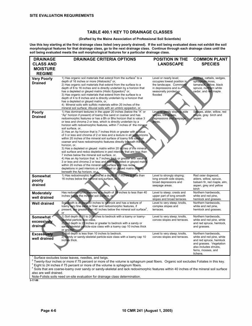
SITE EVALUATION REQUIREMENTS
Page 4-6 10 CMR 241 (August 1, 2005)
TABLE 400.1 KEY TO DRAINAGE CLASSES (Drafted by the Maine Association of Professional Soil Scientists)
Use this key starting at the first drainage class listed (very poorly drained). If the soil being evaluated does not exhibit the soil morphological features for that drainage class, go to the next drainage class. Continue through each drainage class until the soil being evaluated meets the soil morphological features for a particular drainage class.
DRAINAGE CLASS AND MOISTURE
REGIME
DRAINAGE CRITERIA OPTIONS POSITION IN THE LANDSCAPE
COMMON PLANT SPECIES
Very Poorly Drained
1) Has organic soil materials that extend from the surface1 to a depth of 16 inches or more (Histosols)2 or, 2) Has organic soil materials that extend from the surface to a depth of 8 to 16 inches and is directly underlain by a horizon that has a depleted or gleyed matrix (Histic Epipedon)3 or, 3) Has organic soil materials that extend from the surface to a depth of 4 to 8 inches and is directly underlain by a horizon that has a depleted or gleyed matrix, or, 4) Mineral soils with sulfidic materials within 20 inches of the mineral soil surface; Alluvial soils with an umbric epipedon, or,
Level or nearly level; occupies lowest position in the landscape. Commonly in depressions and is seasonally ponded or flooded
Rushes, cattails, sedges, sphagnum moss, tamarack, willow, black spruce, northern white cedar, and red maple.
Poorly Drained
1) Has dominant textures in the upper 20 inches (below the “A” or “Ap” horizon if present) of loamy fine sand or coarser and has redoximorphic features or has a Bh or Bhs horizon that is value 3 or less and chroma 2 or less, which is directly underlain by a horizon with redoximorphic features, within 7 inches of the mineral soil surface, or, 2) Has an Ap horizon that is 7 inches thick or greater with a value of 3 or less and chroma of 2 or less and a texture in all subhorizons within 20 inches of the mineral soil surface of loamy fine sand or coarser and have redoximorphic features directly beneath the Ap horizon, or, 3) Has a depleted or gleyed matrix within 20 inches of the mineral soil surface and redox depletions in ped interiors that are less than 7 inches below the mineral soil surface, or, 4) Has an Ap horizon that is 7 inches thick or greater with value of 3 or less and chroma 2 or less and has a depleted or gleyed matrix within 20 inches of the mineral soil surface and has redox depletions in ped interiors or a depleted or gleyed matrix directly beneath the Ap horizon, or
Level to gently sloping; side slopes, toe slopes, depressions and seepage areas.
Sedges, alder, willow, red maple, gray birch and aspen
Somewhat poorly drained
1) Has redoximorphic features at a depth of 7 inches to less than 16 inches below the mineral soil surface, or
Level to strongly sloping; long smooth side slopes, broad depressions and seepage areas.
Red osier dogwood, alders, willow, spruce, balsam fir, red maple, elm, aspen, grey and yellow birch
Moderately well drained
Has redoximorphic features at a depth of 16 inches to less than 40 inches below the mineral soil surface, or
Level to steep; crests and upper part of long smooth slopes and broad terraces.
Northern hardwoods, white and red pine, hemlock and grasses.
Well drained Soil depth is at least 20 inches to bedrock and has a texture of loamy very fine sand or finer and redoximorphic features, if present, are greater than 40 inches below the mineral soil surface5, or
Level to very steep; knolls, complex slopes and terraces.
Northern hardwoods, white and red pine, hemlock and grasses.
Somewhat excessively drained
1) Soil depth is 10 to 20 inches to bedrock with a loamy or loamy-skeletal particle-size class. 2) Soil depth is 20 inches or greater to bedrock with a sandy or sandy-skeletal particle-size class with a loamy cap 10 inches thick or greater.
Level to very steep; knolls, convex slopes and terraces.
Northern hardwoods, white and red pine, white and red spruce, hemlock, and grasses.
Excessively well drained
1) Soil depth is less than 10 inches to bedrock. 2) Sandy or sandy-skeletal particle-size class with a loamy cap 10 inches thick.
Level to very steep; knolls, convex slopes and terraces.
Northern hardwoods, white and red pine, white and red spruce, hemlock and grasses. Vegetation also includes shrubs, ferns, mosses, and lichens.
1 Surface excludes loose leaves, needles, and twigs.2 Twenty-four inches or more if 75 percent or more of the volume is sphagnum peat fibers. Organic soil excludes Foliates in this key. 3 Eight to 24 inches if 75 percent or more of the volume is sphagnum fibers. 4 Soils that are coarse-loamy over sandy or sandy-skeletal and lack redoximorphic features within 40 inches of the mineral soil surface also are well drained. Note-Folists soils need on-site evaluation for drainage class determination.
3-17-99

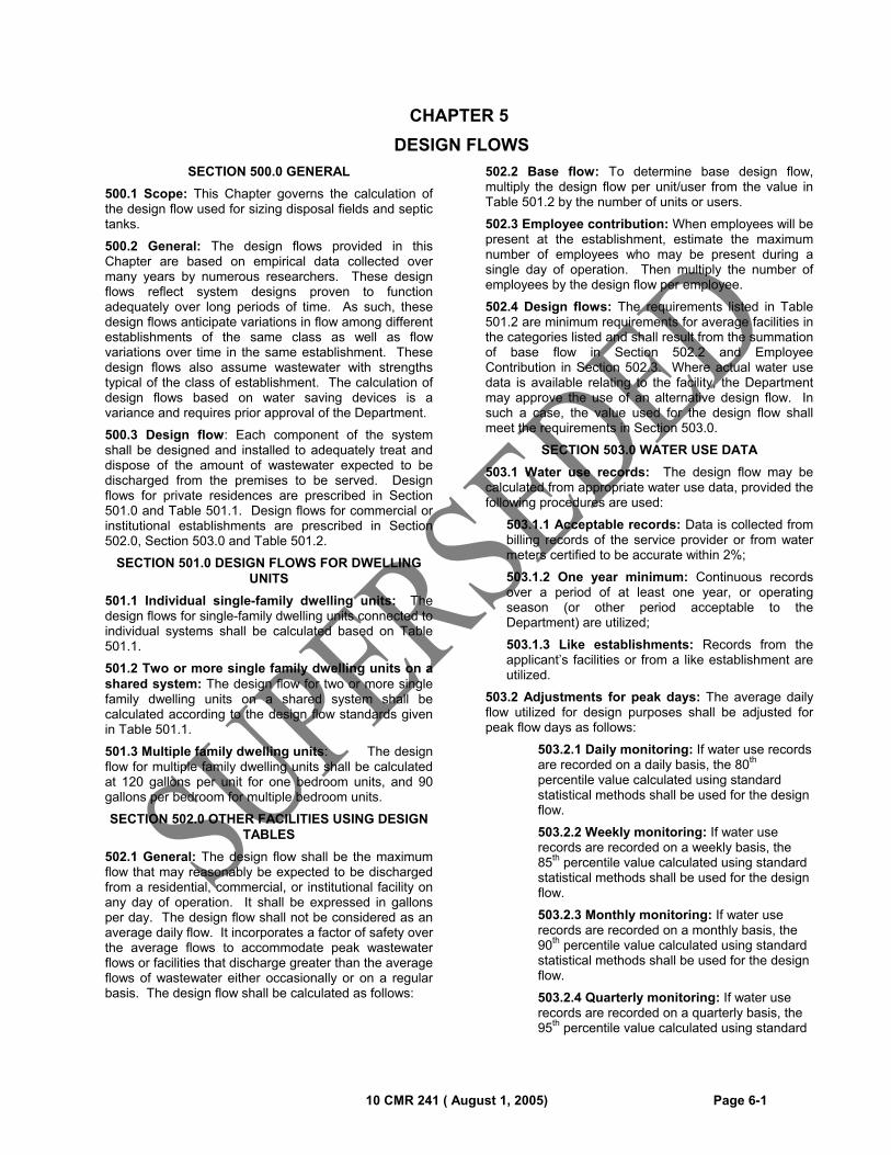
10 CMR 241 ( August 1, 2005) Page 6-1
CHAPTER 5
DESIGN FLOWS
SECTION 500.0 GENERAL
500.1 Scope: This Chapter governs the calculation of the design flow used for sizing disposal fields and septic tanks.
500.2 General: The design flows provided in this Chapter are based on empirical data collected over many years by numerous researchers. These design flows reflect system designs proven to function adequately over long periods of time. As such, these design flows anticipate variations in flow among different establishments of the same class as well as flow variations over time in the same establishment. These design flows also assume wastewater with strengths typical of the class of establishment. The calculation of design flows based on water saving devices is a variance and requires prior approval of the Department.
500.3 Design flow: Each component of the system shall be designed and installed to adequately treat and dispose of the amount of wastewater expected to be discharged from the premises to be served. Design flows for private residences are prescribed in Section 501.0 and Table 501.1. Design flows for commercial or institutional establishments are prescribed in Section 502.0, Section 503.0 and Table 501.2.
SECTION 501.0 DESIGN FLOWS FOR DWELLING UNITS
501.1 Individual single-family dwelling units: The design flows for single-family dwelling units connected to individual systems shall be calculated based on Table 501.1.
501.2 Two or more single family dwelling units on a shared system: The design flow for two or more single family dwelling units on a shared system shall be calculated according to the design flow standards given in Table 501.1.
501.3 Multiple family dwelling units: The design flow for multiple family dwelling units shall be calculated at 120 gallons per unit for one bedroom units, and 90 gallons per bedroom for multiple bedroom units.
SECTION 502.0 OTHER FACILITIES USING DESIGN TABLES
502.1 General: The design flow shall be the maximum flow that may reasonably be expected to be discharged from a residential, commercial, or institutional facility on any day of operation. It shall be expressed in gallons per day. The design flow shall not be considered as an average daily flow. It incorporates a factor of safety over the average flows to accommodate peak wastewater flows or facilities that discharge greater than the average flows of wastewater either occasionally or on a regular basis. The design flow shall be calculated as follows:
502.2 Base flow: To determine base design flow, multiply the design flow per unit/user from the value in Table 501.2 by the number of units or users.
502.3 Employee contribution: When employees will be present at the establishment, estimate the maximum number of employees who may be present during a single day of operation. Then multiply the number of employees by the design flow per employee.
502.4 Design flows: The requirements listed in Table 501.2 are minimum requirements for average facilities in the categories listed and shall result from the summation of base flow in Section 502.2 and Employee Contribution in Section 502.3. Where actual water use data is available relating to the facility, the Department may approve the use of an alternative design flow. In such a case, the value used for the design flow shall meet the requirements in Section 503.0.
SECTION 503.0 WATER USE DATA
503.1 Water use records: The design flow may be calculated from appropriate water use data, provided the following procedures are used:
503.1.1 Acceptable records: Data is collected from billing records of the service provider or from water meters certified to be accurate within 2%;
503.1.2 One year minimum: Continuous records over a period of at least one year, or operating season (or other period acceptable to the Department) are utilized;
503.1.3 Like establishments: Records from the applicant’s facilities or from a like establishment are utilized.
503.2 Adjustments for peak days: The average daily flow utilized for design purposes shall be adjusted for peak flow days as follows:
503.2.1 Daily monitoring: If water use records are recorded on a daily basis, the 80th percentile value calculated using standard statistical methods shall be used for the design flow.
503.2.2 Weekly monitoring: If water use records are recorded on a weekly basis, the 85th percentile value calculated using standard statistical methods shall be used for the design flow.
503.2.3 Monthly monitoring: If water use records are recorded on a monthly basis, the 90th percentile value calculated using standard statistical methods shall be used for the design flow.
503.2.4 Quarterly monitoring: If water use records are recorded on a quarterly basis, the 95th percentile value calculated using standard
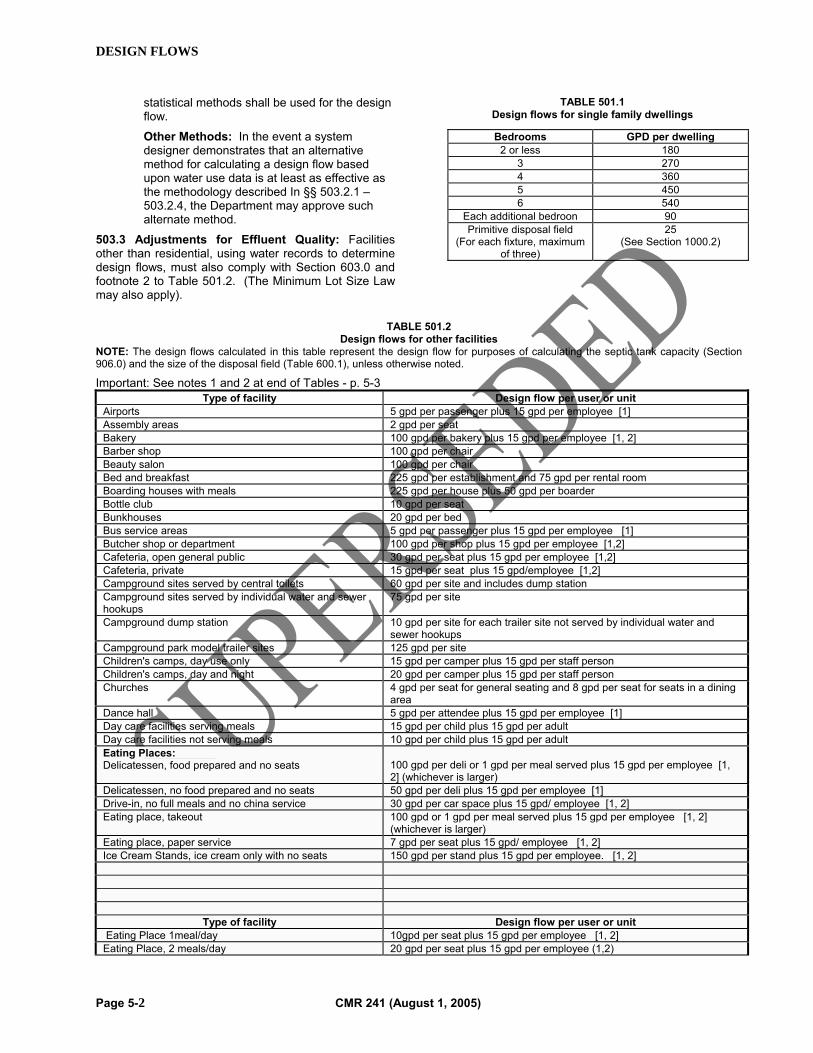
DESIGN FLOWS
Page 5-2 CMR 241 (August 1, 2005)
statistical methods shall be used for the design flow.
Other Methods: In the event a system designer demonstrates that an alternative method for calculating a design flow based upon water use data is at least as effective as the methodology described In §§ 503.2.1 – 503.2.4, the Department may approve such alternate method.
503.3 Adjustments for Effluent Quality: Facilities other than residential, using water records to determine design flows, must also comply with Section 603.0 and footnote 2 to Table 501.2. (The Minimum Lot Size Law may also apply).
TABLE 501.1 Design flows for single family dwellings
TABLE 501.2
Design flows for other facilities NOTE: The design flows calculated in this table represent the design flow for purposes of calculating the septic tank capacity (Section 906.0) and the size of the disposal field (Table 600.1), unless otherwise noted.
Important: See notes 1 and 2 at end of Tables - p. 5-3 Type of facility Design flow per user or unit
Airports 5 gpd per passenger plus 15 gpd per employee [1] Assembly areas 2 gpd per seat Bakery 100 gpd per bakery plus 15 gpd per employee [1, 2] Barber shop 100 gpd per chair Beauty salon 100 gpd per chair Bed and breakfast 225 gpd per establishment and 75 gpd per rental room Boarding houses with meals 225 gpd per house plus 50 gpd per boarder Bottle club 10 gpd per seat Bunkhouses 20 gpd per bed Bus service areas 5 gpd per passenger plus 15 gpd per employee [1] Butcher shop or department 100 gpd per shop plus 15 gpd per employee [1,2] Cafeteria, open general public 30 gpd per seat plus 15 gpd per employee [1,2] Cafeteria, private 15 gpd per seat plus 15 gpd/employee [1,2] Campground sites served by central toilets 60 gpd per site and includes dump station Campground sites served by individual water and sewer hookups
75 gpd per site
Campground dump station 10 gpd per site for each trailer site not served by individual water and sewer hookups
Campground park model trailer sites 125 gpd per site Children's camps, day use only 15 gpd per camper plus 15 gpd per staff person Children's camps, day and night 20 gpd per camper plus 15 gpd per staff person Churches 4 gpd per seat for general seating and 8 gpd per seat for seats in a dining
area Dance hall 5 gpd per attendee plus 15 gpd per employee [1] Day care facilities serving meals 15 gpd per child plus 15 gpd per adult Day care facilities not serving meals 10 gpd per child plus 15 gpd per adult Eating Places: Delicatessen, food prepared and no seats
100 gpd per deli or 1 gpd per meal served plus 15 gpd per employee [1, 2] (whichever is larger)
Delicatessen, no food prepared and no seats 50 gpd per deli plus 15 gpd per employee [1] Drive-in, no full meals and no china service 30 gpd per car space plus 15 gpd/ employee [1, 2] Eating place, takeout 100 gpd or 1 gpd per meal served plus 15 gpd per employee [1, 2]
(whichever is larger) Eating place, paper service 7 gpd per seat plus 15 gpd/ employee [1, 2] Ice Cream Stands, ice cream only with no seats 150 gpd per stand plus 15 gpd per employee. [1, 2]
Type of facility Design flow per user or unit Eating Place 1meal/day 10gpd per seat plus 15 gpd per employee [1, 2] Eating Place, 2 meals/day 20 gpd per seat plus 15 gpd per employee (1,2)
Bedrooms GPD per dwelling 2 or less 180
3 270 4 360 5 450 6 540
Each additional bedroon 90 Primitive disposal field
(For each fixture, maximum of three)
25 (See Section 1000.2)
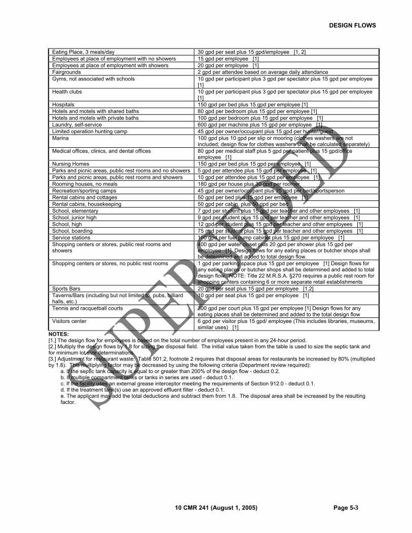
DESIGN FLOWS
10 CMR 241 (August 1, 2005) Page 5-3
Eating Place, 3 meals/day 30 gpd per seat plus 15 gpd/employee [1, 2] Employees at place of employment with no showers 15 gpd per employee [1] Employees at place of employment with showers 20 gpd per employee [1] Fairgrounds 2 gpd per attendee based on average daily attendance Gyms, not associated with schools 10 gpd per participant plus 3 gpd per spectator plus 15 gpd per employee
[1] Health clubs 10 gpd per participant plus 3 gpd per spectator plus 15 gpd per employee
[1] Hospitals 150 gpd per bed plus 15 gpd per employee [1] Hotels and motels with shared baths 80 gpd per bedroom plus 15 gpd per employee [1] Hotels and motels with private baths 100 gpd per bedroom plus 15 gpd per employee [1] Laundry, self-service 600 gpd per machine plus 15 gpd per employee [1] Limited operation hunting camp 45 gpd per owner/occupant plus 15 gpd per hunter/guest Marina 100 gpd plus 10 gpd per slip or mooring (clothes washers are not
included; design flow for clothes washers shall be calculated separately) Medical offices, clinics, and dental offices 80 gpd per medical staff plus 5 gpd per patient plus 15 gpd/office
employee [1] Nursing Homes 150 gpd per bed plus 15 gpd per employee [1] Parks and picnic areas, public rest rooms and no showers 5 gpd per attendee plus 15 gpd per employee [1] Parks and picnic areas, public rest rooms and showers 10 gpd per attendee plus 15 gpd per employee [1] Rooming houses, no meals 180 gpd per house plus 30 gpd per roomer Recreation/sporting camps 45 gpd per owner/occupant plus 25 gpd per bed/sportsperson Rental cabins and cottages 50 gpd per bed plus 15 gpd per employee [1] Rental cabins, housekeeping 50 gpd per cabin, plus 50 gpd per bed School, elementary 7 gpd per student plus 15 gpd per teacher and other employees [1] School, junior high 9 gpd per student plus 15 gpd per teacher and other employees [1] School, high 12 gpd per student plus 15 gpd per teacher and other employees [1] School, boarding 75 gpd per student plus 15 gpd per teacher and other employees [1] Service stations 100 gpd per fuel pump cabinet plus 15 gpd per employee [1] Shopping centers or stores, public rest rooms and showers
400 gpd per water closet plus 20 gpd per shower plus 15 gpd per employee [1] Design flows for any eating places or butcher shops shall be determined and added to total design flow.
Shopping centers or stores, no public rest rooms 1 gpd per parking space plus 15 gpd per employee [1] Design flows for any eating places or butcher shops shall be determined and added to total design flow. NOTE: Title 22 M.R.S.A. §270 requires a public rest room for shopping centers containing 6 or more separate retail establishments
Sports Bars 20 gpd per seat plus 15 gpd per employee [1,2] Taverns/Bars (including but not limited to, pubs, billiard halls, etc.)
10 gpd per seat plus 15 gpd per employee [1]
Tennis and racquetball courts 300 gpd per court plus 15 gpd per employee [1] Design flows for any eating places shall be determined and added to the total design flow
Visitors center 6 gpd per visitor plus 15 gpd/ employee (This includes libraries, museums, similar uses) [1]
NOTES: [1.] The design flow for employees is based on the total number of employees present in any 24-hour period. [2.] Multiply the design flows by 1.8 for sizing the disposal field. The initial value taken from the table is used to size the septic tank and for minimum lot size determinations. [3.] Adjustment for restaurant waste: Table 501.2, footnote 2 requires that disposal areas for restaurants be increased by 80% (multiplied by 1.8). This multiplying factor may be decreased by using the following criteria (Department review required): a. If the septic tank capacity is equal to or greater than 200% of the design flow - deduct 0.2.
b. If multiple compartment tanks or tanks in series are used - deduct 0.1. c. If the facility uses an external grease interceptor meeting the requirements of Section 912.0 - deduct 0.1. d. If the treatment tank(s) use an approved effluent filter - deduct 0.1. e. The applicant may add the total deductions and subtract them from 1.8. The disposal area shall be increased by the resulting factor.

DESIGN FLOWS
Page 5-4 CMR 241 (August 1, 2005)
10 CMR 241 ( August 1, 2005) Page 6-1
CHAPTER 6
DISPOSAL FIELDS
SECTION 600.0 GENERAL
600.1 Scope: This Chapter governs the requirements for disposal field design.
600.2 General: The design of a disposal field is dependent on the soil profile, type of the most limiting factor plus the volume and quality of the wastewater and depth to the most limiting factor. Design Classes are used to describe both the soil limitations observed within the proposed disposal field and the required minimum design features. Design Classes are described in Table 600.1.
600.3 Owner/operator: The owner/operator shall accurately describe the intended uses (present and future) for the system. The owner shall operate the system within the design parameters, except as provided for in Section 1702, Expansion or Change in Use of Existing Structures, following the designer’s recommendations for inspection and maintenance, as well as any State or local regulations.
600.4 Disposal field required: An approved disposal field is needed for all structures requiring subsurface wastewater disposal, unless the structure is served by a holding tank complying with Chapter 20 or is served by an alternative toilet with no gray wastewater generated.
600.5 Kinds of disposal fields: For the purposes of this code, disposal fields include leach trenches, leach beds, proprietary disposal devices, peat disposal fields, or privies designed and installed in compliance with this code.
600.6 Sizing requirements: The size of a disposal field’s required infiltration area is determined using design factors in compliance with Section 603.0 and Table 600.1 and design flows in compliance with Chapter 5.
600.7 Installation: A disposal field may be installed on any site that is in compliance with Tables 600.2 through 600.4 and is in compliance with the Minimum Lot Size Law.
600.8 Vehicular traffic: Except where site limitations make it impractical, no driveway or parking or turning area may be located over any disposal field. When a system is placed under an area receiving vehicular traffic, H-20 loading components shall be installed.
600.9 Infiltration: Rain, surface, and ground water shall not be drained into any component of a system.
SECTION 601.0 LIMITING FACTORS
601.1 General: For the purpose of determining the design class, the soils in the area beneath the proposed disposal field(s) shall meet or exceed the criteria of the design class, as specified in Table 600.1 and Tables 600.2 through 600.4. When two or more conditions are observed, the more limiting of the two conditions shall be
used. See Section 1102.4 (Engineered disposal systems) for additional soil data requirements.
SECTION 602.0 SPECIAL CONSIDERATIONS
602.1 Soil profile 10: Disposal fields on Profile 10 soils shall comply with Table 600.3 and they shall receive prior approval of the plumbing inspector and the Department. First time systems and non-exempted expansion systems are not allowed on Profile 10 soils.
602.2 Soil profile 11: Soil profile 11 is an alluvial soil and its texture varies with the deposition process that laid it down. Therefore, for design purposes, use the soil profile class that best fits the observed soil textures.
602.3 Sites with two or more soil profiles: When two or more soil or profile classes are observed under a proposed disposal field, the design shall be based on the soil profile class which requires the largest disposal field.
602.4 Elevated disposal fields: All disposal fields designed entirely in fill material shall be sized using the disposal field size category of the original soil profile class observed below the fill material or the fill material, whichever requires the largest disposal field.
602.5 Lined disposal fields: Disposal fields designed with liners shall be sized using the medium disposal field size category (2.6 sq. ft./gpd).
602.6 Serial distribution: Serial distribution may be utilized when the following conditions have been met:
602.6.1 Pitch of connecting pipes: The pitch of the connecting pipes is ¼ inch per foot (2 percent) or greater.
602.6.2 Separation distance: The separation distance between rows shall be as indicated in Appendix B.
SECTION 603.0 WASTEWATER STRENGTH ADJUSTMENTS FACTORS
603.1 General: The size of the disposal field shall be adjusted utilizing the factors listed in Table 603.1 when the wastewater entering a disposal field has a combined 5-day biochemical oxygen demand (BOD5) and total suspended solid (TSS) concentration not equal to 240 milligrams per liter,.
603.1.1 Values less than 240 mg/L: The size of a stone disposal field may be reduced by use of the appropriate factor from Table 603.1. The size of a proprietary device disposal field may be reduced by use of the appropriate factor from Table 603.1, provided a reduction is allowed by the manufacturer.
603.1.2 Values greater than 240 and less than or equal to 2,000 mg/L: The size of a disposal field shall be increased by use of the appropriate factor from Table 603.1.
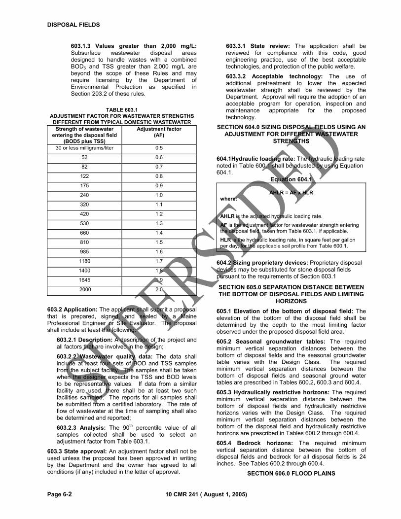
DISPOSAL FIELDS
Page 6-2 10 CMR 241 ( August 1, 2005)
603.1.3 Values greater than 2,000 mg/L: Subsurface wastewater disposal areas designed to handle wastes with a combined BOD5 and TSS greater than 2,000 mg/L are beyond the scope of these Rules and may require licensing by the Department of Environmental Protection as specified in Section 203.2 of these rules.
TABLE 603.1
ADJUSTMENT FACTOR FOR WASTEWATER STRENGTHS DIFFERENT FROM TYPICAL DOMESTIC WASTEWATER Strength of wastewater
entering the disposal field (BOD5 plus TSS)
Adjustment factor (AF)
30 or less milligrams/liter 0.5
52 0.6
82 0.7
122 0.8
175 0.9
240 1.0
320 1.1
420 1.2
530 1.3
660 1.4
810 1.5
985 1.6
1180 1.7
1400 1.8
1645 1.9
2000 2.0
603.2 Application: The applicant shall submit a proposal that is prepared, signed, and sealed by a Maine Professional Engineer or Site Evaluator. The proposal shall include at least the following:
603.2.1 Description: A description of the project and all factors that are involved in the design;
603.2.2 Wastewater quality data: The data shall include at least four sets of BOD and TSS samples from the subject facility. The samples shall be taken when the designer expects the TSS and BOD levels to be representative values. If data from a similar facility are used, there shall be at least two such facilities sampled. The reports for all samples shall be submitted from a certified laboratory. The rate of flow of wastewater at the time of sampling shall also be determined and reported;
603.2.3 Analysis: The 90th percentile value of all samples collected shall be used to select an adjustment factor from Table 603.1.
603.3 State approval: An adjustment factor shall not be used unless the proposal has been approved in writing by the Department and the owner has agreed to all conditions (if any) included in the letter of approval.
603.3.1 State review: The application shall be reviewed for compliance with this code, good engineering practice, use of the best acceptable technologies, and protection of the public welfare.
603.3.2 Acceptable technology: The use of additional pretreatment to lower the expected wastewater strength shall be reviewed by the Department. Approval will require the adoption of an acceptable program for operation, inspection and maintenance appropriate for the proposed technology.
SECTION 604.0 SIZING DISPOSAL FIELDS USING AN ADJUSTMENT FOR DIFFERENT WASTEWATER
STRENGTHS
604.1Hydraulic loading rate: The hydraulic loading rate noted in Table 600.1 shall be adusted by using Equation 604.1.
Equation 604.1
AHLR = AF x HLR where:
AHLR is the adjusted hydraulic loading rate.
AF is the adjustment factor for wastewater strength entering the disposal field, taken from Table 603.1, if applicable.
HLR is the hydraulic loading rate, in square feet per gallon per day, for the applicable soil profile from Table 600.1.�
604.2 Sizing proprietary devices: Proprietary disposal devices may be substituted for stone disposal fields pursuant to the requirements of Section 603.1
SECTION 605.0 SEPARATION DISTANCE BETWEEN THE BOTTOM OF DISPOSAL FIELDS AND LIMITING
HORIZONS
605.1 Elevation of the bottom of disposal field: The elevation of the bottom of the disposal field shall be determined by the depth to the most limiting factor observed under the proposed disposal field area.
605.2 Seasonal groundwater tables: The required minimum vertical separation distances between the bottom of disposal fields and the seasonal groundwater table varies with the Design Class. The required minimum vertical separation distances between the bottom of disposal fields and seasonal ground water tables are prescribed in Tables 600.2, 600.3 and 600.4.
605.3 Hydraulically restrictive horizons: The required minimum vertical separation distance between the bottom of disposal fields and hydraulically restrictive horizons varies with the Design Class. The required minimum vertical separation distances between the bottom of the disposal field and hydraulically restrictive horizons are prescribed in Tables 600.2 through 600.4.
605.4 Bedrock horizons: The required minimum vertical separation distance between the bottom of disposal fields and bedrock for all disposal fields is 24 inches. See Tables 600.2 through 600.4.
SECTION 606.0 FLOOD PLAINS
DISPOSAL FIELDS
10 CMR 241 ( August 1, 2005) Page 6-3
606.1 Assumptions: This Section assumes the major impact of flooding is a reduction in the life expectancy of a system. Ten (10) years is a realistic frequency to allow for partial flood water inundation of a system. More frequent flooding can be expected to reduce the design life of the system.
606.2 First time systems: First time systems are not allowed in:
606.2.1 Freshwater body flood plains: First time systems shall not be installed within the 10-year flood zone. (Note: Some municipalities restrict new development in the 100-year flood plain. Check local ordinances.)
606.2.2 Coastal flood plains: First time systems shall not be installed within the V-Zone indicated by the most current Federal Insurance Rate Maps or below the 10-year storm surge elevation, whichever is more restrictive. The 10-year storm surge elevation in Maine is approximately the 8-foot National Geodetic Vertical Datum.
606.3 Replacement systems: Replacement systems may be permitted in flood plains, if the LPI agrees that no practical alternative exists.
SECTION 607.0 DISPOSAL FIELD “FOOTPRINT”
607.1 Definition of footprint: For purposes of these Rules, the disposal field “footprint” shall mean that area identified as a “disposal field” for setback or separation measurement purposes.
607.1.1 Conventional (stone) system: The horizontal measurement location shall be at the interface of the stone and soil. The top (vertical) measurement shall be from the top of the hay layer or fabric. The bottom measurement shall be from the interface of the stone and soil.
607.1.2 Proprietary device system (no stone or gravel utilized): The horizontal measurement location shall be at the interface of the proprietary device and the soil. The top (vertical) measurement shall be from the top of the proprietary device or fabric. The bottom measurement shall be from the interface of the proprietary device and soil.
607.1.3 Proprietary device with stone adjacent to devices: The measurement location shall be at the interface of the stone and soil.
607.1.4 Proprietary device with stone beneath devices: The measurement location shall be at the interface of the stone and soil.
NOTE: See next page for Table 600.1 Soil Profile, Soil Condition, and Design Class.
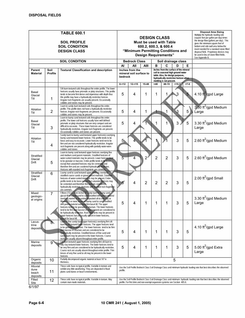
DISPOSAL FIELDS
Page 6-4 10 CMR 241 ( August 1, 2005)
TABLE 600.1
SOIL PROFILE SOIL CONDITION DESIGN CLASS�
DESIGN CLASS
Must be used with Table 600.2, 600.3, & 600.4
“Minimum Permitting Conditions and Design Requirements”
Disposal Area Sizing Multiply the hydraulic loading rate (square feet per gallon per day) times the design flow (gallons per day). This gives the minimum square feet of bottom and side wall area below the invert needed for a standard stone filled disposal field. Proprietary devices may be used in lieu of stone filled fields. See Appendix B.
SOIL CONDITION Bedrock Class Soil drainage class AI AII AIII B C D E Parent Material
Soil Profile
Textural Classification and description Inches from the mineral soil surface to bedrock
Inches from the surface of the mineral soil to seasonal high ground water table. Also, for design purposes, hydraulically restrictive horizon when mottling is not present.
0-<12 12-<15 15-48 >48 48-15 <15-7 <7-0 Basal Glacial Till
1
Silt loam textured soils throughout the entire profile. The lower horizons usually have prismatic or platy structures. This profile tends to become firm dense and impervious with depth thus this profile may have a hydraulically restrictive horizon. Angular rock fragments are usually present. Occasionally cobbles and stones may be present.
5
4
1
1
1
3
5
4.10 ft2/gpd Large
Ablation Till
2
Loam to sandy loam textured soils throughout the entire profile. This profile does not have a hydraulically restrictive horizon. Angular rock fragments are present. Occasionally cobbles and stones may be present.
5
4
1
1
1
3
5
3.30 ft2/gpd Medium Large
Basal Glacial Till
3
Loam to loamy sand textured soils throughout the entire profile. The lower soil horizons usually have well defined prismatic or platy structures that are very compact and are difficult to excavate. These lower horizons are considered hydraulically restrictive. Angular rock fragments are present. Occasionally cobbles and stones are present.
5
4
1
1
1
3
5
3.30 ft2/gpd Medium Large
Ablation Till
4
Sandy loam to loamy sand textured upper horizon(s) overlying loamy sand textured lower horizon. This profile tends to be loose and easy to excavate. Lower horizons tend not to be firm and are not considered hydraulically restrictive. Angular rock fragments are present along with partially water-worn cobbles and stones
5
4
1
1
1
3
5
2.60 ft2/gpd Medium
Stratified Glacial Drift
5
Loam to loamy sand textured upper horizons overlying fine and medium sand parent materials. Stratified horizons of water-sorted materials may be present. Lower horizons tend to be granular or massive. Entire profile tends to be loose except that saturated horizons may be cemented and therefore firm and are cosidered hydraulically restrictive. Horizons with rounded rock fragments are common.
5
4
2
2
2
3
5
2.60 ft2/gpd Medium
Stratified Glacial Drift
6 Loamy sand to sand textured upper horizons overlying stratified coarse sands or gravel parent materials. Stratified horizons of water-sorted materials may be present. Entire profile tends to be loose except that saturated horizons may be cemented and therefore firm and are considered hydraulically restrictive. Horizons with rounded rock fragments are common.
5
4
2
2
2
3
5
2.00 ft2/gpd Small
Mixed geologic-al origins
7 Fifteen (15) or more inches of sandy loam to loamy sand glacial till or loamy sand to sand stratified drift parent material overlying marine or lacustrine deposited silt to silty clay or fifteen (15) or more inches of loamy sand to sand stratified drift parent material overlying firm basal till. The upper horizons tend to be granular in structure. The lower horizons tend to be firm and massive in structure and are considered to be hydraulically restrictive. Rock fragments may be present in upper horizons but are usually absent in lower horizons, except for basal till.
5
4
1
1
1
3
5
3.30 ft2/gpd Medium Large
Lacus- trine deposits
8 Loam to fine sandy loam upper horizon(s) overlying firm silt loam to silt textured lower horizons. The upper horizons tend to be granular in structure. The lower horizons tend to be firm and massive in structure and are considered to be hydraulically restrictive. Stratified lenses of fine sand and sandy loam may be present in the lower horizons. Coarse rocks are usually absent throughout entire profile.
5
4
1
1
1
3
5
4.10 ft2/gpd Large
Marine deposits
9 Silt loam textured upper horizons overlying firm silt loam to silty clay textured lower horizons. The lower horizons tend to be very firm and are considered to be hydraulically restrictive. Coarse rock are usually absent throughout entire profile. Thin lenses of very fine sand to silt may be present in the lower horizons
5
4
1
1
1
3
5
5.00 ft2/gpd Extra Large
Organic deposits
10 Partially decomposed organic material at least 16” in thickness. 5
Alluvial dune beach deposits
11
These soils have no typical profile. Variable in texture and exhibit very little weathering. They are deposited in flood plains sand dunes or beach environments.
Use the Soil Profile Bedrock Class Soil Drainage Class and minimum hydraulic loading rate that best describes the observed profile.
Filled Site
12 These soils have no typical profile. Variable in texture. May contain man-made materials.
Use the Soil Profile Bedrock Class Soil Drainage Class and minimum hydraulic loading rate that best describes the observed profile. For first time and non-exempt expansion systems see Section 405.0.
6/1/97
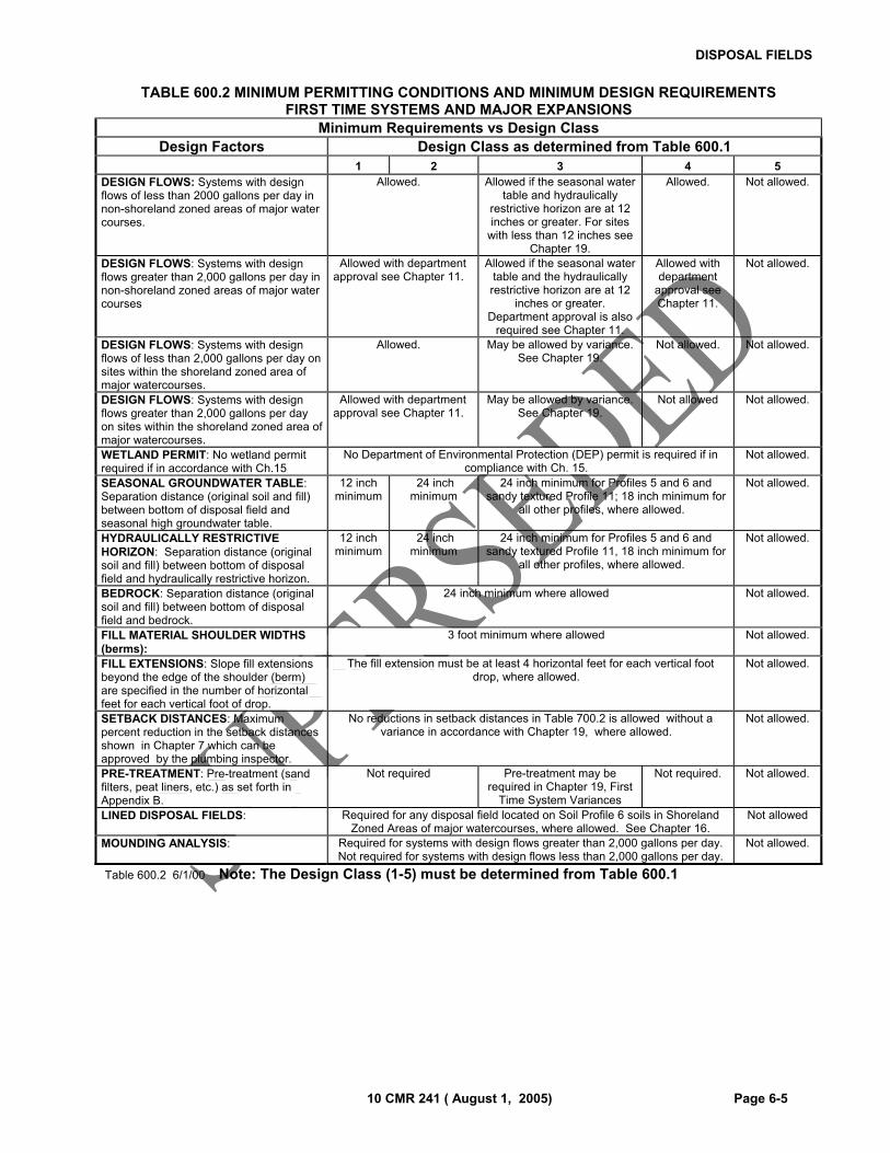
DISPOSAL FIELDS
10 CMR 241 ( August 1, 2005) Page 6-5
TABLE 600.2 MINIMUM PERMITTING CONDITIONS AND MINIMUM DESIGN REQUIREMENTS
FIRST TIME SYSTEMS AND MAJOR EXPANSIONS
Minimum Requirements vs Design Class Design Factors Design Class as determined from Table 600.1
1 2 3 4 5 DESIGN FLOWS: Systems with design flows of less than 2000 gallons per day in non-shoreland zoned areas of major water courses.
Allowed.� Allowed if the seasonal water table and hydraulically
restrictive horizon are at 12 inches or greater. For sites
with less than 12 inches see Chapter 19.
Allowed. Not allowed.
DESIGN FLOWS: Systems with design flows greater than 2,000 gallons per day in non-shoreland zoned areas of major water courses
Allowed with department approval see Chapter 11.�
Allowed if the seasonal water table and the hydraulically restrictive horizon are at 12
inches or greater. Department approval is also
required see Chapter 11.
Allowed with department
approval see Chapter 11.
Not allowed.
DESIGN FLOWS: Systems with design flows of less than 2,000 gallons per day on sites within the shoreland zoned area of major watercourses.
Allowed.� May be allowed by variance. See Chapter 19.
Not allowed. Not allowed.
DESIGN FLOWS: Systems with design flows greater than 2,000 gallons per day on sites within the shoreland zoned area of major watercourses.
Allowed with department approval see Chapter 11.�
May be allowed by variance. See Chapter 19.
Not allowed Not allowed.
WETLAND PERMIT: No wetland permit required if in accordance with Ch.15
No Department of Environmental Protection (DEP) permit is required if in compliance with Ch. 15.�
Not allowed.
SEASONAL GROUNDWATER TABLE: Separation distance (original soil and fill) between bottom of disposal field and seasonal high groundwater table.
12 inch minimum
24 inch minimum
24 inch minimum for Profiles 5 and 6 and sandy textured Profile 11; 18 inch minimum for
all other profiles, where allowed.�
Not allowed.
HYDRAULICALLY RESTRICTIVE HORIZON: Separation distance (original soil and fill) between bottom of disposal field and hydraulically restrictive horizon.
12 inch minimum
24 inch minimum
24 inch minimum for Profiles 5 and 6 and sandy textured Profile 11, 18 inch minimum for
all other profiles, where allowed.�
Not allowed.
BEDROCK: Separation distance (original soil and fill) between bottom of disposal field and bedrock.
24 inch minimum where allowed� Not allowed.
FILL MATERIAL SHOULDER WIDTHS (berms):
3 foot minimum where allowed� Not allowed.
FILL EXTENSIONS: Slope fill extensions beyond the edge of the shoulder (berm) are specified in the number of horizontal feet for each vertical foot of drop.
The fill extension must be at least 4 horizontal feet for each vertical foot drop, where allowed.�
Not allowed.
SETBACK DISTANCES: Maximum percent reduction in the setback distances shown in Chapter 7 which can be approved by the plumbing inspector.
No reductions in setback distances in Table 700.2 is allowed without a variance in accordance with Chapter 19, where allowed.�
Not allowed.
PRE-TREATMENT: Pre-treatment (sand filters, peat liners, etc.) as set forth in Appendix B.
Not required� Pre-treatment may be required in Chapter 19, First
Time System Variances
Not required. Not allowed.
LINED DISPOSAL FIELDS: Required for any disposal field located on Soil Profile 6 soils in Shoreland Zoned Areas of major watercourses, where allowed. See Chapter 16.
Not allowed
MOUNDING ANALYSIS: Required for systems with design flows greater than 2,000 gallons per day. Not required for systems with design flows less than 2,000 gallons per day.
Not allowed.
Table 600.2 6/1/00 Note: The Design Class (1-5) must be determined from Table 600.1

DISPOSAL FIELDS
Page 6-6 10 CMR 241 ( August 1, 2005)
TABLE 600.3 MINIMUM PERMITTING CONDITIONS AND MINIMUM DESIGN REQUIREMENTS ALL REPLACEMENT SYSTEMS AND EXPANSIONS OUTSIDE THE SHORELAND ZONE OF MAJOR
WATERBODIES/COURSES Minimum Requirements vs Design Class
Design Factors Design Class as determined from Table 600.1
1 2 3 4 5 DESIGN FLOWS: Systems with design flows of less than 1,000 gallons per day.
Allowed. Allowed. If the seasonal water table
or hydraulically restrictive layer are at less than 12 inches,
requires prior LPI approval.
(See Ch. 19)
Allowed. Allowed with LPI approval and a
department variance. (See
Ch. 19)
DESIGN FLOWS: Systems with design flows of 1,000 to 2,000 gallons per day.
Allowed. Allowed. If the seasonal water table
or hydraulically restrictive layer are at less than 12 inches,
requires prior LPI approval.
(See Ch. 19)
Allowed. Allowed with LPI approval and a
department variance
(See Ch. 19)
DESIGN FLOWS: Systems with design flows greater than 2,000 gallons per day.
Allowed. Department approval is required. See Chapter 11.
WETLAND PERMIT: No wetland permit required if in accordance with Ch. 15.
No Department of Environmental Protection (DEP) permit is required if in compliance with Ch. 15.
SEASONAL GROUNDWATER TABLE: Separation distance (original soil and fill) between bottom of disposal field and seasonal high groundwater table.
12 inch minimum
24 inch minimum for Profiles 5 and 6 and sandy textured Profile 11. 18 inch minimum for all other profiles unless the site evaluator determines there is no practical alternative and the plumbing inspector agrees. However, the separation distance must be at least 12 inches.
24 inch minimum
HYDRAULICALLY RESTRICTIVE HORIZON: Separation distance (original soil and fill) between bottom of disposal field and hydraulically restrictive horizon.
12 inch minimum
24 inch minimum for Profiles 5 and 6 and sandy textured Profile 11. 18 inch minimum for all other profiles unless the site evaluator determines there is no practical alternative and the plumbing inspector agrees. However, the separation distance must be at least 12 inches.
24 inch minimum
BEDROCK: Separation distance (original soil and fill) between bottom of disposal field and bedrock.
24 inch minimum
FILL MATERIAL SHOULDER WIDTHS (berms)
3 foot minimum
FILL EXTENSIONS: Slope fill extensions beyond the edge of the shoulder (berm) are specified in the number of horizontal feet for each vertical foot of drop.
The fill extension must be at least 4 horizontal feet for each vertical foot drop unless the site evaluator determines there is no practical alternative and the plumbing inspector agrees.
SETBACK DISTANCES: Maximum percent reduction in the setback distances shown in Chapter 7 which can be approved by the plumbing inspector.
If possible, the setbacks must meet the distances shown in Table 700.2. If the setbacks cannot be met, the plumbing inspector is authorized to reduce the setback distances as shown in Table 700.3. Lesser setbacks require a variance from the department and the
plumbing inspector. See Chapter 19.
PRE-TREATMENT: Pre-treatment (sand filters, peat liners, etc.) as set forth in Appendix B.
May be required by the department on sites with severe limitations.
LINED DISPOSAL FIELDS Required for any disposal field located on Soil Profile 6 soils in Shoreland Zone Areas of Major Waterbodies/courses. See Chapter 16.
MOUNDING ANALYSIS Required for systems with design flows greater than 2,000 gallons per day. Not required for systems with design flows less than 2,000 gallons per day.
Table 600.3 10/1/02 Note: The Design Class (1-5) must be determined from Table 600.1
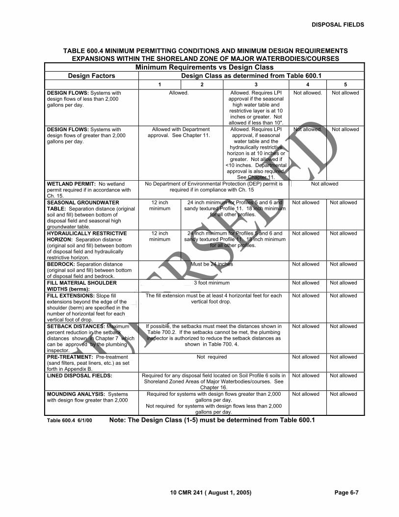
DISPOSAL FIELDS
10 CMR 241 ( August 1, 2005) Page 6-7
TABLE 600.4 MINIMUM PERMITTING CONDITIONS AND MINIMUM DESIGN REQUIREMENTS EXPANSIONS WITHIN THE SHORELAND ZONE OF MAJOR WATERBODIES/COURSES
Minimum Requirements vs Design Class Design Factors Design Class as determined from Table 600.1
1 2 3 4 5 DESIGN FLOWS: Systems with design flows of less than 2,000 gallons per day.
Allowed.� Allowed. Requires LPI approval if the seasonal
high water table and restrictive layer is at 10 inches or greater. Not
allowed if less than 10".
Not allowed. Not allowed
DESIGN FLOWS: Systems with design flows of greater than 2,000 gallons per day.
Allowed with Department approval. See Chapter 11.�
Allowed. Requires LPI approval, if seasonal water table and the
hydraulically restrictive horizon is at 10 inches or
greater. Not allowed if <10 inches. Departmental approval is also required.
See Chapter 11.
Not allowed. Not allowed
WETLAND PERMIT: No wetland permit required if in accordance with Ch. 15.
No Department of Environmental Protection (DEP) permit is required if in compliance with Ch. 15�
Not allowed�
SEASONAL GROUNDWATER TABLE: Separation distance (original soil and fill) between bottom of disposal field and seasonal high groundwater table.
12 inch minimum
24 inch minimum for Profiles 5 and 6 and sandy textured Profile 11. 18 inch minimum
for all other profiles.�
Not allowed� Not allowed�
HYDRAULICALLY RESTRICTIVE HORIZON: Separation distance (original soil and fill) between bottom of disposal field and hydraulically restrictive horizon.
12 inch minimum
24 inch minimum for Profiles 5 and 6 and sandy textured Profile 11. 18 inch minimum
for all other profiles.�
Not allowed� Not allowed�
BEDROCK: Separation distance (original soil and fill) between bottom of disposal field and bedrock.
Must be 24 inches� Not allowed� Not allowed�
FILL MATERIAL SHOULDER WIDTHS (berms):
3 foot minimum� Not allowed� Not allowed�
FILL EXTENSIONS: Slope fill extensions beyond the edge of the shoulder (berm) are specified in the number of horizontal feet for each vertical foot of drop.
The fill extension must be at least 4 horizontal feet for each vertical foot drop. �
Not allowed� Not allowed�
SETBACK DISTANCES: Maximum percent reduction in the setback distances shown in Chapter 7 which can be approved by the plumbing inspector.
If possible, the setbacks must meet the distances shown in Table 700.2. If the setbacks cannot be met, the plumbing inspector is authorized to reduce the setback distances as
shown in Table 700. 4.�
Not allowed� Not allowed�
PRE-TREATMENT: Pre-treatment (sand filters, peat liners, etc.) as set forth in Appendix B.
Not required� Not allowed� Not allowed�
LINED DISPOSAL FIELDS: Required for any disposal field located on Soil Profile 6 soils in Shoreland Zoned Areas of Major Waterbodies/courses. See
Chapter 16.
Not allowed� Not allowed�
MOUNDING ANALYSIS: Systems with design flow greater than 2,000
Required for systems with design flows greater than 2,000 gallons per day.
Not required for systems with design flows less than 2,000 gallons per day.
Not allowed� Not allowed�
Table 600.4 6/1/00 Note: The Design Class (1-5) must be determined from Table 600.1

DISPOSAL FIELDS
Page 6-8 10 CMR 241 ( August 1, 2005)
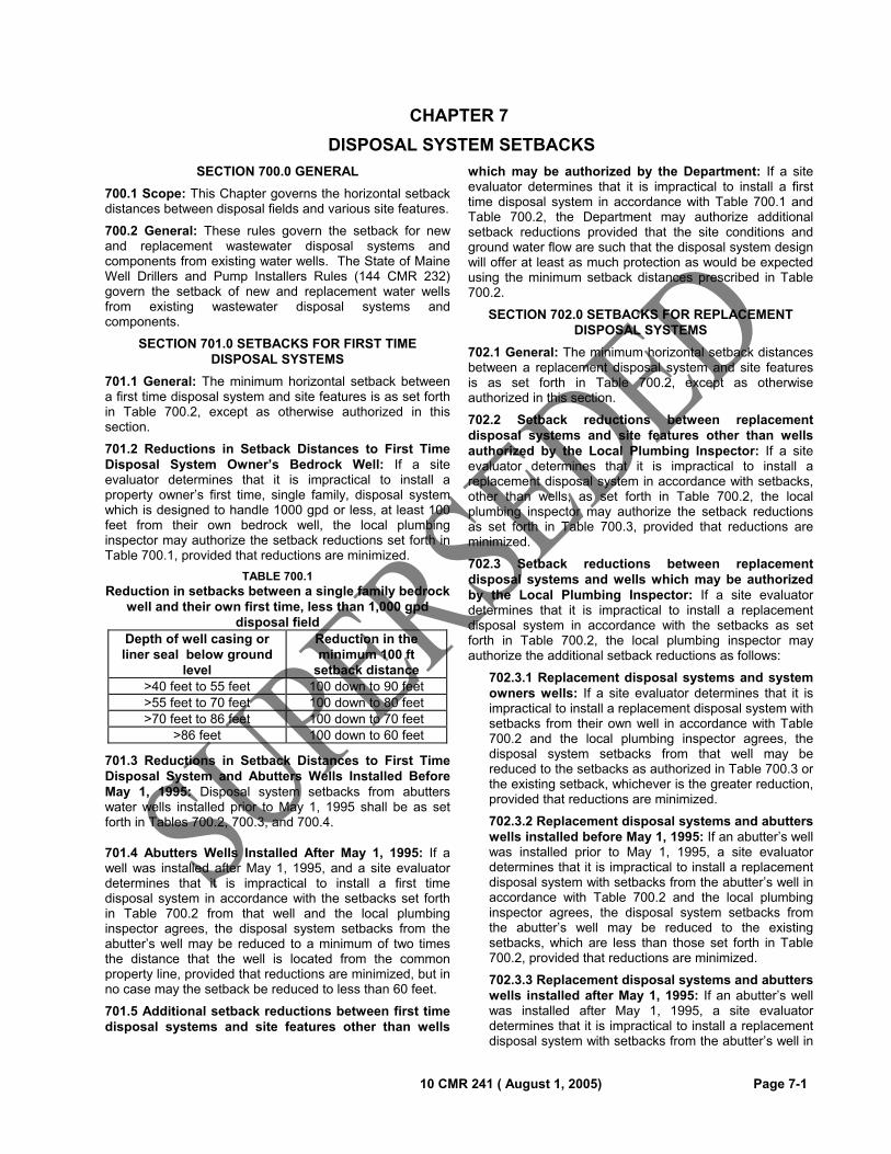
10 CMR 241 ( August 1, 2005) Page 7-1
CHAPTER 7
DISPOSAL SYSTEM SETBACKS
SECTION 700.0 GENERAL
700.1 Scope: This Chapter governs the horizontal setback distances between disposal fields and various site features.
700.2 General: These rules govern the setback for new and replacement wastewater disposal systems and components from existing water wells. The State of Maine Well Drillers and Pump Installers Rules (144 CMR 232) govern the setback of new and replacement water wells from existing wastewater disposal systems and components.
SECTION 701.0 SETBACKS FOR FIRST TIME DISPOSAL SYSTEMS
701.1 General: The minimum horizontal setback between a first time disposal system and site features is as set forth in Table 700.2, except as otherwise authorized in this section.
701.2 Reductions in Setback Distances to First Time Disposal System Owner’s Bedrock Well: If a site evaluator determines that it is impractical to install a property owner’s first time, single family, disposal system which is designed to handle 1000 gpd or less, at least 100 feet from their own bedrock well, the local plumbing inspector may authorize the setback reductions set forth in Table 700.1, provided that reductions are minimized.
TABLE 700.1 Reduction in setbacks between a single family bedrock
well and their own first time, less than 1,000 gpd disposal field
Depth of well casing or liner seal below ground
level
Reduction in the minimum 100 ft
setback distance >40 feet to 55 feet 100 down to 90 feet>55 feet to 70 feet 100 down to 80 feet>70 feet to 86 feet 100 down to 70 feet
>86 feet 100 down to 60 feet
701.3 Reductions in Setback Distances to First Time Disposal System and Abutters Wells Installed Before May 1, 1995: Disposal system setbacks from abutters water wells installed prior to May 1, 1995 shall be as set forth in Tables 700.2, 700.3, and 700.4.
701.4 Abutters Wells Installed After May 1, 1995: If a well was installed after May 1, 1995, and a site evaluator determines that it is impractical to install a first time disposal system in accordance with the setbacks set forth in Table 700.2 from that well and the local plumbing inspector agrees, the disposal system setbacks from the abutter’s well may be reduced to a minimum of two times the distance that the well is located from the common property line, provided that reductions are minimized, but in no case may the setback be reduced to less than 60 feet.
701.5 Additional setback reductions between first time disposal systems and site features other than wells
which may be authorized by the Department: If a site evaluator determines that it is impractical to install a first time disposal system in accordance with Table 700.1 and Table 700.2, the Department may authorize additional setback reductions provided that the site conditions and ground water flow are such that the disposal system design will offer at least as much protection as would be expected using the minimum setback distances prescribed in Table 700.2.
SECTION 702.0 SETBACKS FOR REPLACEMENT DISPOSAL SYSTEMS
702.1 General: The minimum horizontal setback distances between a replacement disposal system and site features is as set forth in Table 700.2, except as otherwise authorized in this section.
702.2 Setback reductions between replacement disposal systems and site features other than wells authorized by the Local Plumbing Inspector: If a site evaluator determines that it is impractical to install a replacement disposal system in accordance with setbacks, other than wells, as set forth in Table 700.2, the local plumbing inspector may authorize the setback reductions as set forth in Table 700.3, provided that reductions are minimized.
702.3 Setback reductions between replacement disposal systems and wells which may be authorized by the Local Plumbing Inspector: If a site evaluator determines that it is impractical to install a replacement disposal system in accordance with the setbacks as set forth in Table 700.2, the local plumbing inspector may authorize the additional setback reductions as follows:
702.3.1 Replacement disposal systems and system owners wells: If a site evaluator determines that it is impractical to install a replacement disposal system with setbacks from their own well in accordance with Table 700.2 and the local plumbing inspector agrees, the disposal system setbacks from that well may be reduced to the setbacks as authorized in Table 700.3 or the existing setback, whichever is the greater reduction, provided that reductions are minimized.
702.3.2 Replacement disposal systems and abutters wells installed before May 1, 1995: If an abutter’s well was installed prior to May 1, 1995, a site evaluator determines that it is impractical to install a replacement disposal system with setbacks from the abutter’s well in accordance with Table 700.2 and the local plumbing inspector agrees, the disposal system setbacks from the abutter’s well may be reduced to the existing setbacks, which are less than those set forth in Table 700.2, provided that reductions are minimized.
702.3.3 Replacement disposal systems and abutters wells installed after May 1, 1995: If an abutter’s well was installed after May 1, 1995, a site evaluator determines that it is impractical to install a replacement disposal system with setbacks from the abutter’s well in
DISPOSAL SYSTEM SETBACKS
Page 7-2 10 CMR 241 ( August 1, 2005)
accordance with Table 700.2 and the local plumbing inspector agrees, the disposal system setbacks from the abutter’s well may be reduced to a minimum of two times the distance that the abutter’s well is located from the common property line, but not less than 60 feet, provided that reductions are minimized unless the existing setback is less than 60 feet in which case a reduction to the existing setback distance may be authorized.
702.4 Additional setback reductions between replacement disposal systems and site features other than wells which may be authorized by the Department: If a site evaluator determines that it is impractical to install a replacement disposal system in accordance with setbacks authorized by the local plumbing inspector, there is no practical alternative and the local plumbing inspector agrees, the Department may approve the additional setback reductions it determines to be reasonable and appropriate on a site specific, case-by-case, basis for features other than wells.
702.5 Additional setback reductions between replacement disposal systems and the system owner’s well which may be authorized by the Department: If a site evaluator determines that it is impractical to install a replacement disposal system in accordance with the setbacks authorized by the local plumbing inspector from their own well, the Department may authorize additional setback reductions, on a site specific, case-by-case basis provided that: there is no practical alternative, the local plumbing inspector agrees, reductions are minimized, all owners give written permission and the well owner(s) have filed a statement in a form (HHE-306) prescribed by the Department, with the Registry of Deeds indicating that the system setbacks from the well are substandard. This statement shall be cross-referenced to the property’s deed by book and page number.
702.6 Additional setback reductions between replacement disposal systems and abutters wells which may be authorized by the Department: If a site evaluator determines that it is impractical to install a replacement disposal system in accordance with setbacks authorized by the local plumbing inspector from an abutter’s well, there is no practical alternative and the local plumbing inspector agrees, the Department may authorize additional setback reductions, on a site specific, case-by-case basis provided that: there is no practical alternative, the local plumbing inspector agrees, reductions are minimized, all owners give written permission and the well owner(s) have filed a statement in a form (HHE-306) prescribed by the Department, with the Registry of Deeds indicating that the system setbacks from the well are substandard. This statement shall be cross-referenced to the property’s deed by book and page number.
703.0 SETBACKS FOR EXPANDED SYSTEMS
703.1 General: The minimum horizontal setback distances between expanded disposal systems and site features are as set forth in Table 700.2, except as otherwise authorized in this section.
703.2 Reduction in setbacks from minor expansion systems located outside of the shoreland zone of major waterbodies/courses: If a site evaluator determines that it is impractical to install a minor expansion disposal system located outside of the shoreland zone of a major waterbody/course in accordance with Table 700.2, and the local plumbing inspector agrees, the setback reductions set forth in section 702.0, replacement disposal systems, may be authorized by the local plumbing inspector.
703.3 Reduction in setbacks from minor expansion systems located within the shoreland zone of major waterbodies/courses: If a site evaluator determines that it is impractical to install a minor expansion disposal system located within the shoreland zone of a major waterbody/course in accordance with Table 700.2 and the local plumbing inspector agrees, the setback reductions for site features other than wells set forth in Table 700.4 may be authorized by the local plumbing inspector, provided that reductions are minimized. For setback reductions to wells as set forth in Table 700.4, conditions for approval shall include: no practical alternative, reductions are minimized and all owners give their written permission for a reduction in the minimum distance between a well and a minor expansion disposal system.
SECTION 704.0 PUBLIC WATER SYSTEM WELLS
704.1 General: Wells which serve public water systems are regulated by the Environmental Protection Agency through the Drinking Water Program of the Division of Environmental Health. Public water systems may include motels, schools, restaurants, factories, apartment buildings and condominiums.
704.2 Setback from public water system well: All disposal fields must be at least 300 feet from any public water system well. All treatment tanks must be at least 150 feet from any public water system well.
704.3 Waiver to setback from public water system well: The Department may grant waivers to 704.2 on a case-by-case, site-specific basis. Any waivers granted may require additional engineering, construction inspection and increased monitoring of the water supply.
SECTION 705.0 NATURAL RESOURCES PROTECTION ACT
705.1 General: Activities in or adjacent to coastal wetlands, special freshwater wetlands, great ponds and water courses are regulated by the Maine Department of Environmental Protection.
705.2 Setbacks: Setbacks shall be maintained between system components and wetlands or water bodies as listed in Tables 700.2 through 700.4. In accordance with Sections 1504.2.1 and 1504.2.2, a setback buffer shall be established between the upland edge or boundary of coastal wetlands, special freshwater wetlands, great ponds and water courses and filling, excavating, bulldozing, or scraping of the adjacent land. (See the setback example in illustration 705.0 at the end of this chapter.)
705.2.1 Slopes of less than 20%: On sustained slopes of less than 20%, a 25 foot setback shall be maintained
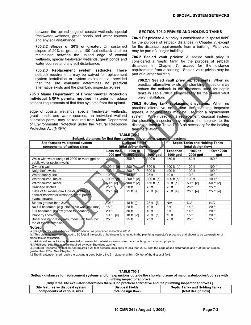
DISPOSAL SYSTEM SETBACKS
10 CMR 241 ( August 1, 2005) Page 7-3
between the upland edge of coastal wetlands, special freshwater wetlands, great ponds and water courses and any soil disturbance.
705.2.2 Slopes of 20% or greater: On sustained slopes of 20% or greater, a 100 foot setback shall be maintained between the upland edge of coastal wetlands, special freshwater wetlands, great ponds and water courses and any soil disturbance.
705.2.3 Replacement system setbacks: These setback requirements may be waived for replacement system installation or system maintenance, provided that the site evaluator determines no practical alternative exists and the plumbing inspector agrees.
705.3 Maine Department of Environmental Protection individual NRPA permits required: In order to reduce setback requirements of first time systems from the upland
edge of coastal wetlands, special freshwater wetlands, great ponds and water courses, an individual wetland alteration permit may be required from Maine Department of Environmental Protection under the Natural Resources Protection Act (NRPA).
SECTION 706.0 PRIVIES AND HOLDING TANKS
706.1 Pit privies: A pit privy is considered a “disposal field” for the purpose of setback distances in Chapter 7, except for the distance requirements from a building. Pit privies may be part of a larger building.
706.2 Sealed vault privies: A sealed vault privy is considered a “septic tank” for the purpose of setback distances in Chapter 7, except for the distance requirements from a building. Sealed vault privies may be part of a larger building.
706.2.1 Sealed vault privy replacements: When no practical alternative exists the plumbing inspector may reduce the setback to the distances listed for septic tanks in Table 700.3 as necessary for the sealed vault privy installation.
706.3 Holding tank replacement systems: When no practical alternative exists and the plumbing inspector agrees, a holding tank may be used for a replacement system. When used for a replacement disposal system, the plumbing inspector may reduce the setback to the distances listed in Table 700.3 as necessary for the holding tank installation.
TABLE 700.2 Setback distances for first time systems and/or major expansion systems
Site features vs disposal system components of various sizes�
Disposal Fields (total design flow)�
Septic Tanks and Holding Tanks (total design flow)
Less than 1000 gpd
1000 to 2000 gpd
Over 2000 gpd
Less than 1000 gpd
1000 to 2000 gpd
Over 2000 gpd
Wells with water usage of 2000 or more gpd or public water system wells
300 ft 300 ft 300 ft 150 ft 150 ft 150 ft
Owner’s well 100 ft [a] 200 ft 300 ft 100 ft [b] 100 ft 100 ft Neighbor’s wells 100 ft 200 ft 300 ft 100 ft 100 ft 100 ft Water supply line 10 ft 18 ft 25 ft 10 ft 10 ft 10 ft Water course, major 100 ft [d] 200 ft [d] 300 ft [d] 100 ft [b] 100 ft 100 ft Water course, minor 50 ft [e] 100 ft [e] 150 ft [e] 50 ft [e] 50 ft [e] 50 ft [e] Drainage ditches 25 ft 50 ft 75 ft 25 ft 25 ft 25 ft Edge of fill extension-- Coastal wetlands, special freshwater wetlands, great ponds, rivers, streams
25 ft [e] 25 ft [e] 25 ft [e] 25 ft [e] 25 ft [e] 25 ft [e]
Slopes greater than 3:1 10f ft 18 ft [f] 25 ft [f] N/A N/A N/A No full basement [e.g. slab, frost wall, columns] 15 ft 28 ft 40 ft 8 ft 14 ft 20 ft Full basement [below grade foundation] 20 ft 30 ft 40 ft 8 ft 14 ft 20 ft Property lines 10 ft [c] 18 ft [c] 20 ft [c] 10 ft 15 ft 20 ft Burial sites or graveyards, measured from the toe of the fill extension
25 ft 25 ft 25 ft 25 ft 25 ft 25 ft
Notes: [a.] Single-family well setbacks may be reduced as prescribed in Section 701.0. [b.] This distance may be reduced to 50 feet, if the septic or holding tank is tested in the plumbing inspector’s presence and shown to be watertight or of monolithic construction. ]c.] Additional setbacks may be needed to prevent fill material extensions from encroaching onto abutting property. [d.] Additional setbacks may be required by local Shoreland zoning. [e.] Natural Resource Protection Act requires a 25 feet setback, on slopes of less than 20%, from the edge of soil disturbance and 100 feet on slopes greater than 20%. See Chapter 15. [f.] The fill extension shall reach the existing ground before the 3:1 slope or within 100 feet of the disposal field.
TABLE 700.3 Setback distances for replacement systems and/or expansions outside the shoreland zone of major waterbodies/courses with
plumbing inspector approval. [Only if the site evaluator determines there is no practical alternative and the plumbing inspector approves.]
Site features vs disposal system components of various sizes
Disposal Fields (total design flow)
Septic Tanks and Holding Tanks (total design flow)
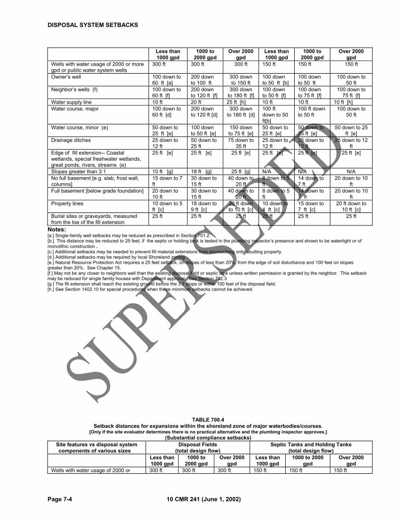
DISPOSAL SYSTEM SETBACKS
Page 7-4 10 CMR 241 (June 1, 2002)
Less than 1000 gpd
1000 to 2000 gpd
Over 2000 gpd
Less than 1000 gpd
1000 to 2000 gpd
Over 2000 gpd
Wells with water usage of 2000 or more gpd or public water system wells
300 ft 300 ft 300 ft 150 ft 150 ft 150 ft
Owner’s well 100 down to 60 ft [a]
200 down to 100 ft
300 down to 150 ft
100 down to 50 ft [b]
100 down to 50 ft
100 down to 50 ft
Neighbor’s wells (f) 100 down to 60 ft [f]
200 down to 120 ft [f]
300 down to 180 ft [f]
100 down to 50 ft [f]
100 down to 75 ft [f]
100 down to 75 ft [f]
Water supply line 10 ft 20 ft 25 ft [h] 10 ft 10 ft 10 ft [h]
Water course, major 100 down to 60 ft [d]
200 down to 120 ft [d]
300 down to 180 ft [d]
100 ft down to 50 ft[b]
100 ft down to 50 ft
100 down to 50 ft
Water course, minor (e) 50 down to 25 ft [e]
100 down to 50 ft [e]
150 down to 75 ft [e]
50 down to 25 ft [e]
50 down to 25 ft [e]
50 down to 25 ft [e]
Drainage ditches 25 down to 12 ft
50 down to 25 ft
75 down to 35 ft
25 down to 12 ft
25 down to 12 ft
25 down to 12 ft
Edge of fill extension-- Coastal wetlands, special freshwater wetlands, great ponds, rivers, streams (e)
25 ft [e] 25 ft [e] 25 ft [e] 25 ft [e] 25 ft [e] 25 ft [e]
Slopes greater than 3:1 10 ft [g] 18 ft [g] 25 ft [g] N/A N/A N/ANo full basement [e.g. slab, frost wall, columns]
15 down to 7 ft
30 down to 15 ft
40 down to 20 ft
8 down to 5 ft
14 down to 7 ft
20 down to 10 ft
Full basement [below grade foundation] 20 down to 10 ft
30 down to 15 ft
40 down to 20 ft
8 down to 5 ft
14 down to 7 ft
20 down to 10 ft
Property lines 10 down to 5 ft [c]
18 down to 9 ft [c]
20 ft down to 10 ft [c]
10 down to 4 ft [c]
15 down to 7 ft [c]
20 ft down to 10 ft [c]
Burial sites or graveyards, measured from the toe of the fill extension
25 ft 25 ft 25 ft 25 ft 25 ft 25 ft
Notes: [a.] Single-family well setbacks may be reduced as prescribed in Section 701.2. [b.] This distance may be reduced to 25 feet, if the septic or holding tank is tested in the plumbing inspector’s presence and shown to be watertight or of monolithic construction . [c.] Additional setbacks may be needed to prevent fill material extensions from encroaching onto abutting property. [d.] Additional setbacks may be required by local Shoreland zoning. [e.] Natural Resource Protection Act requires a 25 feet setback, on slopes of less than 20%, from the edge of soil disturbance and 100 feet on slopes greater than 20%. See Chapter 15. [f.] May not be any closer to neighbors well than the existing disposal field or septic tank unless written permission is granted by the neighbor. This setback may be reduced for single family houses with Department approval. See Section 702.3 [g.] The fill extension shall reach the existing ground before the 3:1 slope or within 100 feet of the disposal field. [h.] See Section 1402.10 for special procedures when these minimum setbacks cannot be achieved.
TABLE 700.4 Setback distances for expansions within the shoreland zone of major waterbodies/courses.
[Only if the site evaluator determines there is no practical alternative and the plumbing inspector approves.] (Substantial compliance setbacks)
Site features vs disposal system components of various sizes�
Disposal Fields (total design flow)
Septic Tanks and Holding Tanks (total design flow)
Less than 1000 gpd
1000 to 2000 gpd
Over 2000 gpd
Less than 1000 gpd
1000 to 2000 gpd
Over 2000 gpd
Wells with water usage of 2000 or 300 ft 300 ft 300 ft 150 ft 150 ft 150 ft
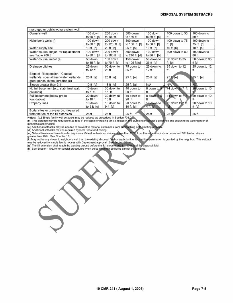
DISPOSAL SYSTEM SETBACKS
10 CMR 241 ( August 1, 2005) Page 7-5
more gpd or public water system well Owner’s well 100 down
to 60 ft [a] 200 down to 100 ft
300 down to 150 ft
100 down to 50 ft [b]
100 down to 50 ft
100 down to 50 ft
Neighbor’s wells (f) 100 down to 60 ft [f]
200 down to 120 ft [f]
300 down to 180 ft [f]
100 down to 50 ft [f]
100 down to 75 ft [f]
100 down to 75 ft [f]
Water supply line 10 ft [h] 20 ft [h] 25 ft [h] 10 ft [h] 10 ft [h] 10 ft [h] Water course, major- for replacement see Table 700.3
100 down to 80 ft [d]
200 down to 160 ft [d]
300 down to 240 ft [d]
100 down to 80 ft [b]
100 down to 80 ft
100 down to 80 ft
Water course, minor (e) 50 down to 35 ft [e]
100 down to 70 ft [e]
150 down to 105 ft [e]
50 down to 35 ft [e]
50 down to 35 ft [e]
50 down to 35 ft [e]
Drainage ditches 25 down to 12 ft
50 down to 25 ft
75 down to 35 ft
25 down to 12 ft
25 down to 12 ft
25 down to 12 ft
Edge of fill extension-- Coastal wetlands, special freshwater wetlands, great ponds, rivers, streams (e)
25 ft [e]
25 ft [e]
25 ft [e]
25 ft [e]
25 ft [e]
25 ft [e]
Slopes greater than 3:1 10 ft [g] 18 ft [g] 25 ft [g] N/A N/A N/A No full basement [e.g. slab, frost wall, columns]
15 down to 7 ft
30 down to 15 ft
40 down to 20 ft
8 down to 5 ft
14 down to 7 ft 20 down to 10 ft
Full basement [below grade foundation]
20 down to 10 ft
30 down to 15 ft
40 down to 20 ft
8 down to 5 ft
14 down to 7 ft 20 down to 10 ft
Property lines 10 down to 5 ft [c]
18 down to 9 ft [c]
20 down to 10 ft [c]
10 down to 4 ft [c]
15 down to 7 ft [c]
20 down to 10 ft [c]
Burial sites or graveyards, measured from the toe of the fill extension
25 ft
25 ft
25 ft
25 ft
25 ft
25 ft
Notes: [a.] Single-family well setbacks may be reduced as prescribed in Section 703.0. [b.] This distance may be reduced to 25 feet, if the septic or holding tank is tested in the plumbing inspector’s presence and shown to be watertight or of monolithic construction. [c.] Additional setbacks may be needed to prevent fill material extensions from encroaching onto abutting property. [d.] Additional setbacks may be required by local Shoreland zoning. [e.] Natural Resource Protection Act requires a 25 feet setback, on slopes of less than 20%, from the edge of soil disturbance and 100 feet on slopes greater than 20%. See Chapter 15. [f.] May not be any closer to neighbors well than the existing disposal field or septic tank unless written permission is granted by the neighbor. This setback may be reduced for single family houses with Department approval. See Section 701.4. [g.] The fill extension shall reach the existing ground before the 3:1 slope or within 100 feet of the disposal field. [h.] See Section 1402.10 for special procedures when these minimum setbacks cannot be achieved.
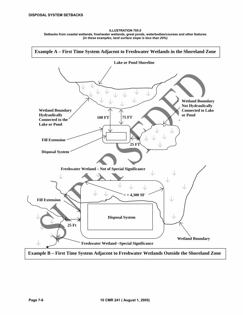
DISPOSAL SYSTEM SETBACKS
Page 7-6 10 CMR 241 ( August 1, 2005)
ILLUSTRATION 705.0 Setbacks from coastal wetlands, freshwater wetlands, great ponds, waterbodies/courses and other features
(in these examples, land surface slope is less than 20%)
Lake or Pond Shoreline
Wetland Boundary Hydraulically Connected to the Lake or Pond
Wetland Boundary Not Hydraulically Connected to Lake or Pond
Disposal System
Fill Extension
100 FT 75 FT
25 FT
Example A – First Time System Adjacent to Freshwater Wetlands in the Shoreland Zone
Freshwater Wetland – Not of Special Significance
Fill Extension
Disposal System
< = 4,300 SF
Wetland Boundary
25 Ft
Freshwater Wetland –Special Significance
Example B – First Time System Adjacent to Freshwater Wetlands Outside the Shoreland Zone
10 CMR 241 ( August 1, 2005) Page 8-1
CHAPTER 8
DISPOSAL FIELD CONSTRUCTION TECHNIQUES
SECTION 800.0 GENERAL
800.1 Intent: This Chapter governs the installation of disposal fields.
800.2 General: On sites with fine soil textures, excavations that expose the bottom and sidewall area of the disposal field shall not be carried out when the soil moisture content is above the plastic limit except when correcting a nuisance, there is no practical alternative, the plumbing inspector agrees and special construction techniques are used. The absolute plastic limit can be estimated by rolling the soil with the fingers. If the soil forms a wire or rod 1/8th of an inch in diameter and does not crumble when handled, the soil moisture content is too high to proceed with the excavation.
800.3 Dig Safe Law: The “Dig Safe Law” 23 MRSA §3360-A places certain notification requirements on any person doing excavations. Excavation is broadly defined to mean any operation in which earth, rock or other material on or below the ground is moved or otherwise displaced by means of power tools, power equipment or explosives and including grading, trenching, digging, ditching, drilling, auguring, tunneling, scraping and cable or pipe driving, except tilling of the soil and gardening or agricultural purposes. For a free Dig Safe in Maine information kit, contact the Maine Public Utilities Commission: 1-800-452-4699 www.state.me.us/mpuc - email: [email protected].
SECTION 801.0 SITE PREPARATION
801.1 Site preparation requirements: Prior to the placement of any backfill material, the ground surface shall be prepared as follows:
801.2 Soil erosion and sediment control: In areas adjacent to a water body or wetlands, preventative erosion and sediment control measures should be employed consistent with Section 1504.0.
801.3 Clearing: Vegetation shall be cut and removed from the area where backfill material is to be placed.
801.4 Scarify the site: Where possible, the area under the disposal field and backfill extensions shall be plowed or disked to produce a thoroughly roughened surface. Plowing shall be done parallel to the topographic contour in such a direction that each plow furrow will be thrown up-slope. The soil should be broken up to a depth of 6 to 8 inches. Alternatively, a roto-tiller or the teeth of a backhoe may be used.
801.5 Transitional horizon: On sites where the backfill material is coarser than the original soil, a minimum of 4 inches of backfill materials must be mixed (by plowing, disking or roto-tilling) into the original soil to form a transitional horizon beneath the disposal area footprint and all side and down slope fill extensions.
801.6 Fill large holes: If large holes are left as a result of stump and/or stone removal, these holes shall be filled with suitable backfill material that meets the requirements of Subsection 803.2.
801.7 Surface water diversion: Surface water shall be diverted away from the disposal field site.
SECTION 802.0 EXCAVATION
802.1 Excavation requirements: Any excavation required for the installation of a disposal field shall comply with all the requirements in this Section.
802.2 Bottom of disposal field: The bottom of each disposal field shall be installed at the elevation specified on the permit. It shall be maintained to a level grade no greater than 2 inches within 100 feet. Note: The bottom of a disposal field serves as the final stage of the distribution network.
802.3 Avoid unnecessary compaction: Excavation shall be carried out in a manner that will avoid unnecessary compaction of both sidewalls and bottom area. Heavy equipment, especially rubber tired vehicles such as front-end loaders, should not be driven over the exposed bottom of the disposal field. Excavation should be carried out, when possible, by a back-hoe operating from outside the perimeter of the previously excavated portions of the disposal fields.
802.4 Reopen smeared or compacted bottom or sidewall surfaces: If any portion of the bottom or sidewalls becomes smeared or compacted, that portion must be scarified to reopen soil pores. Rototilling may be necessary to reach the limit of compacted soil depth.
802.5 Weather conditions: Work should be scheduled so that excavated areas are not exposed to rainfall or wind-blown silt. Any loose soil or debris that is washed or otherwise deposited within the excavation shall be carefully removed prior to backfilling. Additionally, disposal fields should not be installed in frozen ground or when the ambient air temperature is below freezing, especially if construction will take place over several days.
SECTION 803.0 INSTALLATION
803.1 Construction: The installer of the system shall make certain that the system and all its component parts are installed in conformance with the requirements of this code, the plan prepared by the site evaluator, and with any special engineering design requirements approved or required by the Department under Chapter 19.
803.2 Soil and backfill material: The installer of the system shall make certain that the construction and installation are performed without adversely affecting the capacity of the soil or backfill material to adequately absorb or treat the septic tank effluent.
SECTION 804.0 BACKFILL PLACEMENT FOR DISPOSAL AREAS INCLUDING FILL EXTENSIONS
DISPOSAL FIELD CONSTRUCTION TECHNIQUES
Page 8-2 10 CMR 241 ( August 1, 2005)
804.1 General: Selection and placement of backfill shall comply with the requirements of this section.
804.2 Backfill standards: The backfill material shall be a coarse sand to a gravelly coarse sand which meets the following requirements:
804.2.1 Coarse fragments: The upper limit of coarse fragments shall be 3 inches in diameter and approximately 5% by volume;
804.2.2 Textural analysis: The soil texture for backfill, unless otherwise authorized by this code, is coarse sand to gravelly coarse sand with approximately 4 to 8% of the sand, silt and clay fraction passing a #200 sieve. The upper limit of clay sized particles in the sand, silt, and clay fraction shall be approximately 2%. The backfill shall contain approximately 15% to 30% (by weight) coarse fragments (gravel 2 mm to 3 inches).
804.2.3 Field Determination of backfill: Due to the difficulty of obtaining sieve analyses and the variability of backfill material, the following procedures can be used in the field to determine the suitability of backfill material. The backfill is suitable if the soil texture is loose single grains, the individual sand grains can be readily seen (similar to salt or sugar grains) and felt, and the following conditions are observed: If squeezed in the hand when dry, it will fall apart when the pressure is released but has enough fines to stain the lines in the palm of the hand; or, if squeezed when moist, it will form a cast that will crumble when touched and bears very careful handling; and it does not form a ribbon between the thumb and forefinger but has enough fines to stain the lines in the palm of the hand.
804.2.4 Coarser material beneath or beside disposal system: Stone meeting the requirements of Section 805.2 may be placed immediately adjacent to the disposal field provided that the rest of the backfill material meets the requirements of Subsection 804.2. If used beneath the disposal field, it shall be considered part of the disposal field for determining the separation between the limiting factor and the bottom of the disposal system.
804.2.5 Fill material placement above disposal system: Immediately above the filter fabric, hay or proprietary devices, fill is required as specified on the plans. It shall be a minimum of 8 inches in thickness (including cover material).
804.2.6 Cover material: Immediately above the backfill or fill material, at least 4” of soil or soil and soil amendment mix, suitable for establishment of a good vegetative cover, shall be placed over the entire disturbed soil area, including fill extensions.
804.3 Disposal fields installed completely in the original ground: If the disposal field is completely installed in original ground, the backfill material shall completely cover the disposal fields. Fill material extensions shall be graded smoothly into the surrounding
topography on all sides. The disposal field shall be adequately crowned on level disposal fields (3% minimum grade) to allow for settling so that surface water will be allowed to drain from the site without ponding.
804.4 Disposal fields installed partially in the original ground: Disposal fields partially installed in the original ground shall meet the following requirements:
804.4.1 Extent of backfill material: The fill layer shall include any backfill beneath the disposal field, the shoulders, and the backfill material extensions surrounding the disposal field on all sides.
804.4.2 Shoulder width and slope: The minimum required shoulder width is 3 feet. The finished grade of the shoulder shall be sloped at 3% away from the disposal field or conform to the slope of the finish grade of the disposal field.
804.4.3 Sloping sites: On sloping sites, the width of the shoulder may be reduced on the up-slope side of the disposal field. In this case, the top surface of the backfill material shall be kept level with or higher than the invert of the distribution pipes up to the point where the top surface of the fill material intersects with existing slope.
804.4.4 Backfill material extension: At the outside edge of the shoulder, the backfill material shall be terminated by sloping the top of the backfill layer downward at a slope specified in Tables 600.2 through 600.4.
SECTION 805.0 DISPOSAL FIELDS
805.1 Installation requirements: Disposal fields shall be installed in compliance with all the requirements in this Section and Section 1403.0.
805.1.1 Pitch of distribution pipes or proprietary disposal devices: Maximum tolerance of distribution pipes or proprietary disposal devices shall be no more than 2 inches in 100 feet.
805.1.2 Spacing between distribution pipes: The space between distribution pipes for low pressure distribution shall be from 75 to 80% of the hole spacing. Spacing shall be equal and uniform.
805.1.3 Holes in low pressure distribution pipes: The holes in low pressure distribution pipes shall be equal and uniform. The holes shall be aligned so that holes in adjacent distribution pipes are offset by 50% of the hole spacing.
805.1.4 Proprietary devices: Proprietary disposal devices approved by the Department as substitutes for disposal field stone and perforated distribution pipes shall be installed per the manufacturer’s instructions.
805.2 Disposal field stone: The stone used in disposal fields shall meet the following requirements:
805.2.1 General: Where used, the stone shall cover the distribution pipes and extend the full width and length of the disposal field.
DISPOSAL FIELD CONSTRUCTION TECHNIQUES
10 CMR 241 ( August 1, 2005) Page 8-3
805.2.2 Minimum thickness: The disposal field stone depth shall extend at least 7 inches beneath the bottom of the distribution pipes and shall extend at least 1 inch above the top of the distribution pipes.
805.2.3 Stone requirements: The disposal field stone shall be clean, uniform in size and free of fines, dust, ashes, or clay. It shall conform to one of the nominal stone sizes listed in Table 800.1.
TABLE 800.1
Maximum Percent passing by weight Nominal Stone Size
2 ½” 2” 1 ½” 1” ¾”
Sie
ve S
ize
4” 100 100 100 100 100
3” 90 95 100 100 100
2” 10 10 90 95 100
1” 5 5 10 10 90
¾” 4 4 5 5 10
½” 3 3 4 4 5
¼” 2 2 3 3 4
#200 2 2 2 2 2
805.2.3.1 Stone specifications: A site evaluator may define a more stringent standard for stone size for any particular system.
805.2.4 Placing stone: The disposal field stone may be loaded onto the disposal field site using a back-hoe, front-end loader, or dump truck. This operation shall be carried out from the sides of the disposal field rather than by driving onto the prepared area of the disposal field. In the case of large disposal fields, tracked equipment may be operated within the disposal field. This equipment shall not exert a ground pressure in excess of eight pounds per square inch. The disposal field stone shall be pushed in front of the vehicle such that a minimum of one foot of stone is maintained beneath the vehicle track and the original soil surface.
805.3 Covering the disposal field stone: The disposal field stone shall be covered with a layer of filter fabric or two (2) inches of compressed hay as the laying of the distribution pipes progresses. Filter fabric may be used, provided the following requirements are met:
805.3.1 Overlapping filter fabric sheets: Edges of adjacent sheets of fabric shall be overlapped by a minimum of 6 inches; and
805.3.2 Fabric requirements: The filter fabric specified in the system design shall have: adequate tensile strength to prevent ripping during installation and backfilling, adequate air permeability to allow free passage of gases; and adequate particle retention to prevent downward migration of soil particles into the disposal field. The minimum physical properties for
the fabric shall be 4.0 ounces/square yard (per ASTM D-3776).
805.3.3 Prohibited: The use of waterproof paper is prohibited.
SECTION 806.0 FINAL GRADING
806.1 General: Final grading for vegetative stabilized disposal areas shall be carried out in compliance with the requirements of this Section.
806.2 Cover material: At least 4 inches of soil or soil/soil amendment mix, suitable for establishment of a good vegetative cover shall be placed over the entire filled area including the fill material extensions.
806.3 Final grading: Final grading shall be completed in such a manner that surface water will not collect over the disposal field.
806.4 Erosion control: Immediately after completion of final grading, the fill material surface shall be stabilized by mulching and seeding, or sodding, to establish a good vegetative cover to prevent erosion.
806.4.1 Vegetative covers: Grass, clover, trefoil, vetch, perennial wild flowers, or other herbaceous perennials may be utilized for disposal field surfaces.
806.4.2 Other covers: Bark chips, woodchips, pine needles, and other organic materials may be used as cover material when specified by the designer.
806.4.3 Woody shrubs and trees: Woody shrubs or trees are unacceptable on disposal field surfaces. Woody shrubs may be used in conjunction with a hardy perennial ground cover on backfill material extensions only.
SECTION 807.0 CURTAIN DRAINS
807.1 Requirements: Curtain drains, when required, shall be up-slope of the disposal field, approximately perpendicular to the flow of ground water, intercepting and diverting groundwater away from the disposal field.
807.2 Setbacks: The minimum distance between the disposal field and a curtain drain shall be as follows;
807.3 Setback up-slope: A minimum setback distance of 10 feet shall be maintained between a curtain drain and the up-slope edge of a disposal field. The curtain drain shall be located beyond the toe of the uphill fill extension if the uphill extension is greater than 10 feet and constructed so that the curtain drain is located to prevent any under drain of the disposal field.
807.4 Setback cross-slope: A minimum setback distance of 15 feet shall be maintained between a curtain drain and the ends of a disposal field and constructed so that the curtain drain is located to prevent any under drain of the disposal field.
807.5 Free-flowing outlets: Free-flowing outlets shall be provided down-slope of the curtain drain extensions. Outlets shall meet the following requirements:
807.5.1 Discharge point: Outlets may empty into a drainage swale discharging to a surface water body, a groundwater recharge basin, or a gravel bed;
DISPOSAL FIELD CONSTRUCTION TECHNIQUES
Page 8-4 10 CMR 241 ( August 1, 2005)
807.5.2 Outlet design: Outlets shall be designed, installed, located, and maintained in a manner that does not cause soil erosion, surface flooding, or damage to adjacent properties, does not create a public nuisance, and does not violate any applicable Federal, State, or local laws or regulations; and
807.6 Rodent control: Adequate measures shall be taken to protect each outlet from the entry of rodents or other small animals.
807.7 Fill requirements: Fill material over the curtain drain discharge pipes shall be of earth of a texture that is similar to or coarser than that found at the site and free of large stones, stumps, broken masonry, or other waste construction material.
SECTION 808.0 SEPARATION DISTANCE BETWEEN DISPOSAL FIELDS
808.1 Minimum separation distance between disposal fields: Disposal fields, whether part of a single system or two or more discrete systems, shall be separated by a minimum of 5 feet, as measured along the contour, or one half the width of the widest adjacent disposal fields; whichever is greater. 808.2 Setbacks for multiple disposal systems: When there are two or more disposal systems on a single property, separated by less than 100 feet from each other, and the combined wastewater flow exceeds 1,000 gallons per day; each disposal system must meet the setback requirements for the total design flow.
10 CMR 241 ( August 1, 2005) Page 9-1
CHAPTER 9
SEPTIC TANKS, DOSING TANKS, AND GREASE INTERCEPTORS
SECTION 900.0 GENERAL
900.1 Scope: This Chapter governs the design, installation, repair, and maintenance of septic tanks, dosing tanks and grease interceptors.
900.2 Abandoned septic tanks: The property owner or property owner’s agent is responsible for seeing to it that the contents of all abandoned septic tanks are pumped and disposed of properly. The top or entire septic tank shall be removed and the remaining portion of the septic tank or excavation shall be filled immediately.
SECTION 901.0 SEPTIC TANK REQUIRED
901.1 General: Wastewater shall be treated by an approved septic tank prior to being discharged into a disposal field, unless the applicant receives a primitive system permit as described in Section 1001.0, a separate laundry wastewater disposal system permit as described in Section 1008.0 or a holding tank permit as described in Chapter 20. The use of an aerobic treatment unit or any other device in lieu of a septic tank shall not be approved by the plumbing inspector without prior approval by the Department.
SECTION 902.0 SEPTIC TANK CONSTRUCTION MATERIALS
902.1 General: Metal septic tanks are prohibited. Septic tanks may be constructed of the following materials: reinforced poured-in-place concrete, precast reinforced concrete, fiberglass, or polyethylene approved by the Department.
902.2 Concrete: Concrete used in the construction of septic tanks shall meet the American Concrete Institute (ACI) standards for frost resistance (ACI 318-16-4.5.1) and water-tightness (ACI 318-16-4.5.2).
902.3 Fiberglass: Prefabricated fiberglass septic tanks shall meet the American Society for Testing and Materials (ASTM) Standard ASTM D4021.
902.4 Polyethylene: Prefabricated polyethylene septic tanks shall meet the standards for materials, wall thickness, fastening of fittings, and maximum deformation under load prescribed by the Canadian Standards Association (CSA) in CSA Standard CAN3-B66-M79.
SECTION 903.0 SEPTIC TANK DIMENSIONS
903.1 Liquid depth: When the tank is filled to its maximum capacity, the depth of the liquid in the septic tank shall be at least 30 inches.
903.2 Air space: The interior distance between the top of the outlet pipe tee or baffle and the top of the septic tank shall be at least 1 inch.
903.3 Configuration: Tanks shall be constructed such that the direction of flow is along the longest inside dimensions.
903.4 Rectangular septic tanks: The inside length, measured from inside wall to inside wall, shall not be less than 74 inches.
903.5 Cylindrical septic tanks: Upright cylindrical septic tanks shall have a minimum diameter of 52 inches. Horizontal cylindrical septic tanks shall have a minimum length of 72 inches. Their minimum width at the maximum liquid level shall be 36 inches.
SECTION 904.0 INLET AND OUTLET CONNECTIONS
904.1 General: Inlet and outlet connections of each septic tank or compartment shall be designed to obtain effective retention of scum and sludge. All connections and baffles shall be fastened with and constructed of, or coated with, materials that are resistant to corrosion. Where pipe tees are used, the pipe tees shall be sanitary pipe tees and installed in a manner that provides a lasting watertight seal between the pipe tee and the wall of the septic tank. To obtain a watertight seal, a manufactured waterproof coupling may be incorporated into the wall of the septic tank. Expanding grout that will adhere both to the pipe tee and to the body of the septic tank where the pipe tee is installed may be used instead.
904.2 Baffles: A baffle or pipe tee not less than 4 inches in diameter is required at both the inlet and the outlet of a septic tank. The bottom of the baffle or of the vertical leg of the pipe tee at the inlet end of the tank shall extend below the maximum liquid level at least 20 to 30% of the total liquid depth. The baffle or pipe tee at the outlet shall extend from within 1 or 2 inches of the top of the tank to at least 16 inches below the maximum liquid level. It shall block the outlet so that solids and scum cannot exit from the tank. A septic tank filter may be used in lieu of the outlet baffle.
904.3 Inlet connections: The invert elevation of the septic tank inlet shall be at least 2 inches higher than the invert elevation of the septic tank outlet or the outlet of the first compartment. The inverts of the inlets of subsequent compartments shall be at least 1 inch above their outlets. When a baffle is used, the inlet pipe shall be flush with the inside wall of the tank to prevent a buildup of solids between the inlet and the baffle.
904.4 Outlet connections: Outlet connections shall be permanently fastened in place.
SECTION 905.0 ACCESS OPENINGS FOR ALL SEPTIC TANKS
905.1 All septic tanks: Access openings for septic tanks shall meet the following requirements:
905.1.1 Minimum access opening: All septic tanks shall be constructed to provide an access to each tank compartment. Each access shall be: at least 18 inches along the side, if square; at least 18 inches in diameter, if round; and as nearly as possible centered over the compartment.
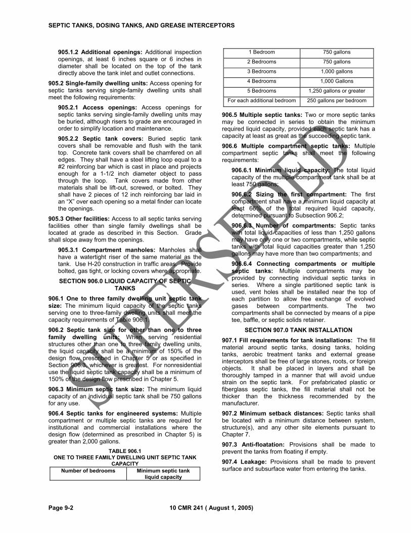
SEPTIC TANKS, DOSING TANKS, AND GREASE INTERCEPTORS
Page 9-2 10 CMR 241 ( August 1, 2005)
905.1.2 Additional openings: Additional inspection openings, at least 6 inches square or 6 inches in diameter shall be located on the top of the tank directly above the tank inlet and outlet connections.
905.2 Single-family dwelling units: Access opening for septic tanks serving single-family dwelling units shall meet the following requirements:
905.2.1 Access openings: Access openings for septic tanks serving single-family dwelling units may be buried, although risers to grade are encouraged in order to simplify location and maintenance.
905.2.2 Septic tank covers: Buried septic tank covers shall be removable and flush with the tank top. Concrete tank covers shall be chamfered on all edges. They shall have a steel lifting loop equal to a #2 reinforcing bar which is cast in place and projects enough for a 1-1/2 inch diameter object to pass through the loop. Tank covers made from other materials shall be lift-out, screwed, or bolted. They shall have 2 pieces of 12 inch reinforcing bar laid in an “X” over each opening so a metal finder can locate the openings.
905.3 Other facilities: Access to all septic tanks serving facilities other than single family dwellings shall be located at grade as described in this Section. Grade shall slope away from the openings.
905.3.1 Compartment manholes: Manholes shall have a watertight riser of the same material as the tank. Use H-20 construction in traffic areas. Provide bolted, gas tight, or locking covers where appropriate.
SECTION 906.0 LIQUID CAPACITY OF SEPTIC TANKS
906.1 One to three family dwelling unit septic tank size: The minimum liquid capacity of the septic tanks serving one to three-family dwelling units shall meet the capacity requirements of Table 906.1.
906.2 Septic tank size for other than one to three family dwelling units: When serving residential structures other than one to three family dwelling units, the liquid capacity shall be a minimum of 150% of the design flow prescribed in Chapter 5 or as specified in Section 906.3, whichever is greatest. For nonresidential use the liquid septic tank capacity shall be a minimum of 150% of the design flow prescribed in Chapter 5.
906.3 Minimum septic tank size: The minimum liquid capacity of an individual septic tank shall be 750 gallons for any use.
906.4 Septic tanks for engineered systems: Multiple compartment or multiple septic tanks are required for institutional and commercial installations where the design flow (determined as prescribed in Chapter 5) is greater than 2,000 gallons.
TABLE 906.1 ONE TO THREE FAMILY DWELLING UNIT SEPTIC TANK
CAPACITY Number of bedrooms Minimum septic tank
liquid capacity
1 Bedroom 750 gallons
2 Bedrooms 750 gallons
3 Bedrooms 1,000 gallons
4 Bedrooms 1,000 Gallons
5 Bedrooms 1,250 gallons or greater
For each additional bedroom 250 gallons per bedroom
906.5 Multiple septic tanks: Two or more septic tanks may be connected in series to obtain the minimum required liquid capacity, provided each septic tank has a capacity at least as great as the succeeding septic tank.
906.6 Multiple compartment septic tanks: Multiple compartment septic tanks shall meet the following requirements:
906.6.1 Minimum liquid capacity: The total liquid capacity of the multiple compartment tank shall be at least 750 gallons;
906.6.2 Sizing the first compartment: The first compartment shall have a minimum liquid capacity at least 66% of the total required liquid capacity, determined pursuant to Subsection 906.2;
906.6.3 Number of compartments: Septic tanks with total liquid capacities of less than 1,250 gallons may have only one or two compartments, while septic tanks with total liquid capacities greater than 1,250 gallons may have more than two compartments; and
906.6.4 Connecting compartments or multiple septic tanks: Multiple compartments may be provided by connecting individual septic tanks in series. Where a single partitioned septic tank is used, vent holes shall be installed near the top of each partition to allow free exchange of evolved gases between compartments. The two compartments shall be connected by means of a pipe tee, baffle, or septic solids retainer.
SECTION 907.0 TANK INSTALLATION
907.1 Fill requirements for tank installations: The fill material around septic tanks, dosing tanks, holding tanks, aerobic treatment tanks and external grease interceptors shall be free of large stones, roots, or foreign objects. It shall be placed in layers and shall be thoroughly tamped in a manner that will avoid undue strain on the septic tank. For prefabricated plastic or fiberglass septic tanks, the fill material shall not be thicker than the thickness recommended by the manufacturer.
907.2 Minimum setback distances: Septic tanks shall be located with a minimum distance between system, structure(s), and any other site elements pursuant to Chapter 7.
907.3 Anti-floatation: Provisions shall be made to prevent the tanks from floating if empty.
907.4 Leakage: Provisions shall be made to prevent surface and subsurface water from entering the tanks.
SEPTIC TANKS, DOSING TANKS, AND GREASE INTERCEPTORS
10 CMR 241 ( August 1, 2005) Page 9-3
907.5 Traffic loading: When tanks are installed under a driveway, parking lot, in a heavily saturated soil, or other areas subject to heavy loads, the tanks shall be able to withstand an H-20 wheel load.
907.6 Bedding: All tanks shall be bedded on a layer of clean sand, gravel, or stone. The bedding material shall extend at least 4 inches beyond the base of the tank.
907.7 Level and accessible: All tanks shall be set level and at the elevation, if shown on the HHE-200, determined by the designer. Tanks shall be readily accessible for maintenance and cleaning.
SECTION 908.0 AEROBIC TREATMENT TANKS
908.1 General: The use of an aerobic treatment unit or any other device in lieu of a septic tank shall not be approved by the plumbing inspector without prior approval by the Department. Any aerobic treatment tank use in lieu of a septic tank shall bear the endorsement of the National Sanitation Foundation’s Standard 40. The size of the aerobic tank shall meet the recommendations provided by the National Sanitation Foundation. No reduction in the size of the disposal field will be allowed.
SECTION 909.0 MAINTENANCE AND SLUDGE DISPOSAL
909.1 Maintenance: Septic tanks and other treatment tanks should be regularly maintained. As a general rule, the tank contents should be removed whenever the sludge and scum occupies one-third of the tank’s liquid capacity.
909.2 Septage disposal: All septage shall be disposed of at a location approved by the Maine Department of Environmental Protection.
SECTION 910.0 SEPTIC TANK CLEANERS AND DEGREASERS
910.1 The use of septic tank degreasers prohibited: The Department does not recognize any product as being beneficial to the operation of a disposal system. The use of septic tank additives containing halogenated hydrocarbon compounds is prohibited by law. See Title 33 MRSA §1602.
SECTION 911.0 DOSING TANKS
911.1 General: All dosing tanks shall be watertight. Materials and construction specifications are the same as those specified for septic tanks in this Chapter. Manholes for dosing tanks shall terminate a minimum of 4 inches above the ground surface.
911.2 Frost protection: In cases where the dosing tanks will be installed above the maximum expected depth of frost penetration, dosing tanks shall be protected with at least 2 inches of high density expanded rigid polystyrene.
911.3 Additional requirements: See Sections 1406.0 and 1407.0.
SECTION 912.0 EXTERNAL GREASE INTERCEPTORS
912.1 General: Any new commercial or institutional food preparation facility, such as a restaurant, cafeteria, or institutional kitchen served by a subsurface wastewater disposal system, shall install an external grease interceptor. Any converted or expanded facility requires an external grease interceptor except when not practical as determined by the Local Plumbing Inspector (LPI); in which case an internal grease interceptor shall be used meeting the requirements of the Maine Plumbing Code.
912.2 Location: The external grease interceptor shall be installed in a separate line serving that part of the plumbing system into which the external grease will be discharged. The external grease interceptor shall be located close to the source of the wastewater, (to keep the grease from solidifying). External grease interceptors shall be installed with an access cover to the surface and located, designed and installed in a manner that will permit easy access for inspection, repair, and cleaning.
912.3 Sizing the external grease interceptors for restaurants: Equation 912.3 shall be used to determine the minimum size of external grease interceptors serving restaurants.
Equation 912.3
Q=[D][HR/2][GL][ST][LF]
where: Q is the liquid capacity of external grease interceptor, gallons; D is the number of seats in dining area; HR is the number of hours open per day; GL is the gallons of wastewater per meal, typ. 2.5 gallons ST is the storage capacity, normally 2; and LF is a loading factor depending on restaurant location;
LF is 1.25 for interstate freeways; LF is 1.0 for recreation areas; LF is 0.8 for State numbered roads; and LF is 0.5 for other roads and highways. �
912.4 Sizing the external grease interceptors for cafeterias and institutional kitchens: Equation 912.4 shall be used to determine the minimum size of external grease interceptors serving cafeterias and institutional kitchens.
Equation 912.4
Q=[M][GL][ST][LF]
where: Q is the liquid capacity of external grease interceptor, gallons; M is the total number of meals served per day; GL is the gallons of wastewater per meal, typ. 2.0 gallons ST is the storage capacity, typ. 2; and LF is a loading factor depending on type of facilities present:
LF is 1.0 with dish washing; and;
SEPTIC TANKS, DOSING TANKS, AND GREASE INTERCEPTORS
Page 9-4 10 CMR 241 ( August 1, 2005)
LF is 0.5 without dish washing.
912.5 Minimum size: In no case may an external grease interceptor serving a restaurant, cafeteria, or institutional kitchen be smaller than 750 gallons liquid capacity. 912.6 Construction: The minimum requirements for construction, materials, and foundations of external grease interceptors are the same as those required for septic tanks. The installation shall be in accordance with Section 907.0.
912.7 Outlet baffle of grease trap: The outlet of the external grease interceptor shall be provided with pipe tee baffle extending to a depth of 12 inches above the tank floor and well above the maximum liquid level. A septic tank filter may be used in lieu of the outlet baffle.
912.8 Maintenance: All external grease interceptors shall be routinely inspected to determine the volume present. All external grease interceptors shall be cleaned when the volume of external grease equals no more than 50% of the liquid capacity of the tank.
SECTION 913.0 IMPACT OF GARBAGE DISPOSALS ON SEPTIC TANK PERFORMANCE
913.1 Garbage disposal: Garbage disposals should not be used with disposal fields. However, if such units are proposed to be used, other measures shall be taken such as: a) increasing septic tank capacity by a minimum of 30%, b) the installation of a second septic tank installed in series, or c) the use of septic tank outlet filters, and d) shall be included in the system design to prevent suspended solids from entering the disposal field.
10 CMR 241 ( August 1, 2005) Page 10-1
CHAPTER 10
PRIMITIVE DISPOSAL SYSTEMS, ALTERNATIVE TOILETS, AND SEPARATED LAUNDRY SYSTEMS
SECTION 1000.0 GENERAL
1000.1 Scope: This Chapter governs the design and installation of primitive systems and alternative toilets.
1000.1.1 Definitions: A primitive disposal system consists of a gray-water disposal field designed to handle hand carried or hand pumped water only and an alternative toilet. A limited system consists of a gray-water disposal field to handle water supplied from elevated storage tanks or cisterns, of no more than 1000 gallons capacity, and portable pumps, among other non-conventional pressurized water supplies.
1000.1.2 Use of alternative toilets: An alternative toilet shall be used if a primitive disposal field is used. An alternative toilet may also be used with a conventional disposal system or in a situation where there is no other structure.
1000.2 Design flows: The design flow for a primitive system shall be 25 gallons of gray wastewater per day. The design flow for a limited system shall be 50 gallons of gray wastewater per fixture per day.
1000.3 Sizing primitive disposal fields: A primitive disposal field shall be sized pursuant to Chapter 6. It shall be installed in compliance with requirements of Chapter 8. A limited system shall be sized in accordance with Section 1000.2.
1000.4 Building sewer: The building sewer between the kitchen sink and the primitive disposal field shall have a minimum diameter of 1.5 inches, a maximum diameter of 2 inches, and a minimum pitch of ¼ inch per foot.
SECTION 1001.0 PRIMITIVE DISPOSAL SYSTEM REQUIREMENTS
1001.1 Requirement: A primitive system may be used where the primitive system will serve a structure for which the water supplied to not more than three (3) gray wastewater fixtures is hand carried or hand pumped. Allowable fixtures are limited to lavatory, shower/tub or sink. No other plumbing fixtures may be connected to the primitive disposal field. A septic tank is not required.
1001.2 Backup system reserve area required: The Site Evaluator shall delineate on the application (HHE-200) a reserve area where a full size disposal area can be installed in compliance with first time system criteria. The owner shall not take or allow any action which would prevent the use of the reserve area for a disposal area installation.
1001.3 System upgrades: Upgrading a disposal system from a primitive to a full size, conventional system must be in compliance with first time system criteria as specified in Tables 600.2 and 700.2.
SECTION 1002.0 ALTERNATIVE TOILETS FOR PERMANENT USE
1002.1 General: “Alternative toilets” may be used for the collection and treatment of human excreta provided such toilets comply with the provisions of this Section.
1002.1.1 Permits required: Permits are required for all alternative toilet installations. Portable alternative toilets do not require a permit.
1002.1.2 Types of alternative toilets: Alternative toilets include chemical toilets and privies, composting toilets, incineration toilets, pit privies, and vault privies.
1002.1.3 Site evaluation not required: In the case of an “alternative toilet” that does not discharge human excreta directly onto or into the soil, a site evaluation is not required for design of the alternative toilet.
1002.2 Disposal of contents: The contents of an alternative toilet shall be removed and disposed of in a legal and sanitary manner whenever they reach the recommended capacity of the alternative toilet.
1002.3 Non-discharging toilets providing treatment and stabilization: Only non-discharging toilets that do not use water carriage, but that do provide treatment or stabilization of the wastes, may be approved for permanent on-site use. All alternative toilets shall meet the requirements of this Subsection in addition to specific requirements that apply to each type of alternative toilet, given in Sections 1003.0 through 1007.0.
1002.3.1 Insects and vermin: The design and installation of all alternative toilets shall prevent access by insects and vermin. Each toilet area shall have a fly-tight, self-closing door and a self-closing toilet seat cover.
1002.3.2 Venting: All vents shall either be gas tight or operate by means of natural convection to keep odors from the structure within which the vents function. Mechanical vents to the outside atmosphere shall be screened to prevent insects and vermin from entering.
SECTION 1003.0 CHEMICAL TOILETS
1003.1 General: A chemical toilet is designed to receive, store, and stabilize human wastes through the use of chemical agents. More chemical agent shall be added as needed. Access to the holding tank or vault shall be available for cleaning purposes. The requirements of this Section are in addition to the general requirements for alternative toilets in Section 1002.0.
PRIMITIVE DISPOSAL SYSTEMS, ALTERNATIVE TOILETS, AND SEPARATED LAUNDRY SYSTEMS
Page 10-2 10 CMR 241 ( August 1, 2005)
1003.2 Storage: A chemical toilet shall have a watertight holding tank or vault for storage of wastes. The holding tank or vault shall be manufactured of impervious materials.
1003.3 Venting: Chemical toilets shall be vented to the outside atmosphere above the roof line of the structure housing them.
1003.4 Chemical flush toilets: Chemical flush toilets shall meet the following additional requirements:
1003.4.1 Chemical flushing agents: The bowl of a chemical flush toilet shall be flushed with chemical agent from a storage tank;
1003.4.2 Traps: A trap shall be installed between each toilet and the holding tank that stores the wastes. If a trap is not feasible, another method of excluding odors may be installed with the approval of the Department; and
1003.4.3 Recirculation: Chemical flushing agents shall pass into a holding tank where solids are removed before the flushing agents can be recirculated.
1003.5 Chemical privies: Chemical privies shall meet the following additional requirements:
1003.5.1 Addition of chemicals: Chemicals shall be added to the vault from outside the toilet area whenever odors or other objectionable conditions occur; and
1003.5.2 Access to vault: There shall be access to the vault from outside the structure for the purpose of cleaning the vault.
SECTION 1004.0 COMPOSTING TOILETS
1004.1 General: A composting toilet is designed to receive, store, and compost human wastes. Stabilized (that is, composted) wastes shall be removed for disposal when the toilet’s storage capacity is reached. The requirements of this Section are in addition to the general requirements for alternative toilets in Section 1002.0.
1004.2 Interior capacity: The minimum interior volume of a composting toilet shall be large enough to allow complete stabilization of all wastes when the toilet is used continuously at its proposed usage level.
1004.3 Waste area: Toilet wastes shall be deposited into a receiving area with a self-closing, tightly fitting lid.
1004.4 Access opening: There shall be a separate access, with a tightly fitting lid, through which food wastes, or other materials needed for the composting process, are routed to the composting compartment.
1004.5 Waste removal: Composted material shall be removed from the storage area through a cleanout opening fitted with a tight door or lid. No cleanout may be located in a food storage or preparation area.
1004.6 Overflow: Any liquid overflow shall be discharged to a primitive or conventional disposal field.
1004.7 Large capacity composting toilets: Large capacity composting toilets shall meet the following additional requirements:
1004.7.1 Construction: Large capacity composting toilets shall be configured to permit the contents to move from one area to another without spillage and without escape of odors within the structure; and
1004.7.2 Venting: The toilets shall be vented to the atmosphere through a screened conduit with a minimum cross sectional area of 28 square inches. Venting may be by mechanical means or by extension of the vent’s outlet at least 20 feet above the opening into receiving and composting areas.
1004.8 Heat-assisted composting toilets: Heat-assisted composting toilets shall meet the following additional requirements:
1004.8.1 Construction: Heat-assisted composting toilets shall have a single compartment with a tight, self-closing toilet lid;
1004.8.2 Venting: There shall be mechanical ventilation to the outside atmosphere through a screened vent. The mechanical ventilation shall control humidity and remove odors through the vent; and
1004.8.3 External heat source: A heating element shall be installed to maintain temperature in the optimum range for composting.
SECTION 1005.0 INCINERATION TOILETS
1005.1 General: An incineration toilet is designed to receive and evaporate/incinerate human wastes and store the sterile ash until it is removed for disposal. In addition to the general requirements for alternative toilets in Section 1002.0, incineration toilets shall meet the following requirements:
1005.2 Other codes: Incineration toilets shall meet all applicable fire and building codes;
1005.3 Incineration: Ignition and incineration shall occur only when the tightly fitting toilet lid is closed;
1005.4 Makeup air: A blower shall operate whenever incineration occurs; and
1005.5 Combustion temperature: The toilet shall maintain a combustion temperature of at least 1400°F.
1005.6 Venting: To minimize odors, the vents shall terminate a minimum of 24 inches above the roof or as per manufacturer’s specifications, whichever is greatest.
SECTION 1006.0 PIT PRIVIES
1006.1 General: Pit privies are intended to receive and store human wastes in an excavation below the toilet(s). A pit privy shall be installed in compliance with the requirements in this Section, in addition to the general requirements for alternative toilets in Section 1002.0.
1006.2 Elevation of the pit bottom: The elevation of the bottom of pit shall maintain the vertical separation
PRIMITIVE DISPOSAL SYSTEMS, ALTERNATIVE TOILETS, AND SEPARATED LAUNDRY SYSTEMS
10 CMR 241 ( August 1, 2005) Page 10-3
distances for disposal fields prescribed in Tables 600.2 through 600.4.
1006.3 Setback distance: A pit privy shall meet “disposal field” setback requirements in accordance with Chapter 7 and Tables 700.2 through 700.4. Exempted is the setback distance from structures where the pit privies may be part of the structure.
1006.4 Maintenance: Proper sanitation shall be maintained in a pit privy. The pit privy building shall be ventilated.
1006.5 Human excreta only: Only human body wastes may be disposed of in a pit privy.
1006.6 Upgrade: The replacement of a pit privy with a combined sewage disposal system is considered an upgrade, and must meet the criteria pursuant to Tables 600.4 and 700.4.
SECTION 1007.0 VAULT PRIVIES
1007.1 General: Vault privies are intended to receive and store human wastes until the wastes are removed for disposal. A vault privy shall be installed in compliance with the requirements in this Section, in addition to the general requirements for alternative toilets in Section 1002.0, “Alternative toilets for permanent use.”
1007.2 Setback distance: A vault privy shall meet the setback requirements established in Subsection 705.2 and 705.2.1 and Tables 700.2 - 700.4. Exempted is the setback distance from structures where seal vault privies may be part of the structure.
1007.3 Sealed vault construction: Seal vaults shall be constructed of materials meeting the requirements of Subsection 902.0.
1007.4 Sizing sealed vaults: Seal vaults shall have a minimum liquid capacity of at least 500 gallons.
1007.5 Installations: Seal vaults shall be installed in accordance with the requirements of Subsection 907.0.
1007.6 Maintenance: Proper sanitation shall be maintained in a vault privy. The privy building shall be ventilated.
1007.7 Human excreta only: Only human body wastes may be disposed of in a vault privy.
1007.8 Preventing flotation: When vault privies are installed at or below the seasonal high water table, the installer shall make sure that flotation of the vault and entrance of surface or ground water will not occur.
1007.9 Venting: Dry vault privies shall provide air venting in through the toilet lid. The vent pipe shall be screened to prevent entry of flies.
1007.10 Access for cleaning: The vault shall be arranged for easy cleaning from outside the toilet.
SECTION 1008.0 SEPARATED LAUNDRY DISPOSAL SYSTEMS
1008.1 General: The plumbing inspector may approve a separated laundry system for single-family dwelling units. A separated laundry field requires an application for
subsurface wastewater disposal system completed by a licensed site evaluator and a permit to install the system. A separated laundry system shall share no components with the main system.
1008.2 Minimum requirements: Separated laundry systems shall meet the requirements of this Section.
1008.3 Only washing wastewater: Only wastewater from a washing machine may be discharged to the separate laundry disposal field designed for that purpose. Separate laundry disposal fields may be designed and used for hot tubs or backwash water.
1008.4 Septic tank not required: A separated laundry disposal field does not require a septic tank.
1008.5 Design flow: Fifty five gallons per day (55 gpd) or 20% of the base design flow, whichever is greater, shall be used as the minimum design flow for sizing a single-family separated laundry disposal field.
1008.6 Disposal field design and construction: Separated laundry disposal fields shall meet all the requirements prescribed in this code for disposal fields.
1008.7 Drain line size: The discharge line between the washing machine and separated laundry disposal field shall be 2 inches in diameter with a grade of not less than ¼ inch per foot.
SECTION 1009.0 GRAY WASTEWATER DISPOSAL SYSTEMS
1009.1 General: The plumbing inspector may approve a gray wastewater disposal system for single-family dwelling units served by pressurized water. A gray wastewater system requires an application for subsurface wastewater disposal system completed by a licensed site evaluator and a permit to install the system. A gray wastewater system shall share no components with the main system.
1009.2 Minimum requirements: Gray wastewater systems shall meet the requirements of this Section.
1009.3 Only gray wastewater: Wastewater from all plumbing fixtures except water closets may be discharged to the gray wastewater disposal field designed for that purpose. Gray wastewater disposal fields may be designed and used for hot tubs or backwash water.
1009.4 Septic tank required: A gray wastewater disposal field requires a septic tank.
1009.5 Design flow: One hundred twenty-six gallons per day (126 gpd) or 70% of the base design flow, whichever is greater, shall be used as the minimum design flow for sizing a single-family gray wastewater disposal field.
1009.6 Disposal field design and construction: Gray wastewater disposal fields shall meet all the requirements prescribed in this code for disposal fields.
1009.7 Drain line size: The building drain and building sewer shall be 3 inches in diameter or greater, with a grade of not less than ¼ inch per foot.

10 CMR 241 ( August 1, 2005) Page 11 -1
CHAPTER 11
ENGINEERED DISPOSAL SYSTEMS
SECTION 1100.0 GENERAL
1100.1 Scope: This Chapter governs the design and installation of engineered systems with design flows of 2,000 gpd or more, or treating raw wastewater with a combined BOD5 and total suspended solids concentration greater than 1,400 mg/l (see Table 603.1).
SECTION 1101.0 RESPONSIBILITIES
1101.1 General: The size and/or complexity of engineered systems require that analysis, design construction, operation, and maintenance be undertaken at a level that is higher than the minimum requirements for small residential systems.
1101.2 Owner/operator: The owner/operator shall accurately describe the intended uses (present and future) for the system, and designate to the Department a Maine licensed professional engineer to serve as design engineer. The owner shall operate the system within the design parameters, except as provided for in Section 1702, Expansion or Change in Use of Existing Structures, following the designer’s recommendations for inspection and maintenance, as well as any State or local regulations.
1101.3 Design engineer: The design engineer is responsible for defining the needs of the client, investigating the site, designing the system, overseeing construction, and recommending operation and maintenance practices at an appropriate level of professional practice. The design engineer shall assure that the design complies with all provisions of applicable laws, ordinances, and regulations, including those administered by public water systems in effect when the system design is completed. The design engineer shall consider the following factors to assure proper functioning under expected conditions, including, but not limited to, peak effluent flows, high water levels, minimum recharge, deep frost, power failure, etc.
1101.4 Department of Health and Human Services: The Department will conduct a desk review of the proposal, check for completeness of submittal (all necessary documents and signatures, etc.), review the reasonableness of data and assumptions, spot-check calculations, check for compliance with minimum requirements of this code and this Section, and give permission to the local government to issue the necessary permits. The Department is not responsible for the accuracy of the field data, assumptions or conclusions of the designer, the suitability of the design, or its performance. In accordance with the Memorandum of Agreement dated June 1998, the Department of Environmental Protection (DEP) will provide assistance to the Department in evaluating environmental impacts of these systems. DEP will submit comments to the Department for consideration prior to final decision.
1101.5 Local government: The local government, operating through the plumbing inspector(s), will issue
the necessary permit(s) after it has received permission from the Department to do so and when it is satisfied that the pre-construction conditions shown on the design are representative of the actual conditions. The local official shall inspect the site in a timely manner in order to be able to state with reasonable assurance that the system was installed as described in the approved plans.
SECTION 1102.0 REQUIREMENTS FOR ENGINEERED DISPOSAL SYSTEM DESIGNS
1102.1 Department approval: An engineered system requires Department approval. A preliminary discussion between the Department; the design engineer and any other consultants as appropriate shall take place to identify any specific requirements related to the application before a final submission for review and approval is made. From the preliminary discussion through acceptance of the Engineer’s statement of compliance, the design engineer shall be the primary point of contact.
1102.2 Plan submission: The plans submitted to the Department shall contain all the information requested on the Engineered System Application Form, required in Chapter 4, and any specific requirements identified in the preliminary discussion in addition to meeting the requirements of this Section. Two sets of plans are required, or one set of plans and one set of copies no larger than 11” x 17”. Additionally, plans may be submitted on a floppy disk or compact disc in Autodesk AUTOCAD*.dwg format.
1102.3 Definition of the facility served: The submission shall define the facility to be served, the flow of the effluent (including variations in quality and quantity), and the current and projected uses of the facility. Design flows should be measured, estimated, and compared to historical (code) values, and safety factors should be used.
1102.4 Determination of soil and site conditions: The soil conditions shall be determined by a Maine Licensed Site Evaluator. The submission shall show site data that represents the soil conditions under the proposed disposal field as indicated in Section 601.1 and under the down slope fill extension. The level of investigation is a function of the basic quality of the site (topography and soils) and the relative size of the system and disposal fields. Observation holes used for design purposes shall be located at representative points within the proposed subsurface wastewater disposal area.
1102.4.1 Minimum number of observation holes: The number of observation holes shall be sufficient to determine the soil and site characteristics beneath the entire disposal field, including the down slope fill material extensions, but shall not be less than three (3) per engineered system.
ENGINEERED DISPOSAL SYSTEMS
Page 11-2 10 CMR 241 ( August 1, 2005)
1102.5 State of the art designs: The submission shall be based on current acceptable practices as it relates to the design of systems.
1102.6 Contour lines: The submission shall include: surficial contours, elevation of observation holes, and location of all site features within 300 feet that require consideration. Pre-development and post-development contours shall be shown both in the areas to be occupied by parts of a system and for a distance of 100 feet beyond the system. The contour intervals shall be no greater than 2 feet.
1102.7 Elevations: The elevation of the bottom of the disposal field(s), the original ground surface at each observation hole, and the top of the distribution pipes or proprietary disposal devices within the disposal field(s), shall be established.
1102.8 Localized mounding analysis: The submission shall include an analysis of the proposed system design and site hydraulics to determine that there will be an adequate vertical separation between the bottom of the disposal field and any mounded water table. This analysis must include all calculations, justification of methodology and assumptions, and other supporting data and documentation. Any additional vertical separation distance needed to offset mounding effects and maintain compliance with Section 605.0 must be stated in the mounding analysis report.
1102.9 Site transmission analysis: The submission shall include an analysis of the proposed system design and site hydraulics to determine that the native soil and/or fill material will have sufficient capacity to prevent wastewater from surfacing down gradient of the disposal field. This standard does not include normal discharges of groundwater to springs, major or minor watercourses, or other surface waters and wetlands located at or beyond setback distances established in Section 7, or lesser setbacks approved by variance, even if these discharges may contain some amount of treated wastewater. Nothing in this paragraph may be interpreted to limit the scope or enforcement of 38 MRSA §413 or other applicable statutes.
1102.10 Operations and Maintenance Manual: The submission shall include an operations and maintenance manual for the owner with written recommendations for the operation and maintenance of the system, including inspection schedules, pumping schedules, and record keeping procedures. Manufacturer’s operations and maintenance manuals for devices and/or equipment may be included in this exhibit, but shall not be a substitute for the exhibit.
1102.11 Pertinent laws, etc.: The submission shall include evidence of compliance with all pertinent laws, ordinances, and regulations.
1102.12 Signatures: The submission and plans shall bear the seal of a professional engineer licensed in Maine and the soil logs should bear the signature of a site evaluator licensed in Maine.
1102.13 System: The proposed system shall be sized in compliance with Chapter 5, Chapter 6 and Chapter 9. It shall meet the minimum setback distances in Chapter 7.
1102.14 Grades: Existing and finished grade within the area of engineered disposal fields, their shoulders and fill material extensions using relative elevations referenced to a permanent system elevation reference point;
1102.15 Reserve area for first time systems: A reserve area with suitable soil conditions shall be delineated on the plan and reserved for the possible expansion or replacement of the proposed engineered system.
1102.16 Pump dose volume: For engineered systems the pump-on and pump-off switches shall be set at appropriate levels to provide a dose volume as required by the manufacturer. The pump-off switch shall be set 6 inches above the pump intake. The pump-on switch shall be set at a distance “d”, in inches above the pump-off switch, that is calculated by means of Equation 1102.14.
Equation 1102.14
D = [1.6][Vd+Vap+Vpd]/[A]
where:
D is the inches above the pump-off switch;
Vd is the required dose volume, in gallons, determined as prescribed in Subsection 1406.4;
Vcp is the internal volume of all distribution pipes and connector piping that will drain back into the dosing tank at the end of a dosing cycle, in gallons;
Vpd is the volume displacement, in gallons, of the pump and controls; and
A is the internal horizontal area of the dosing tank, in square feet.�
1102.17 Review fee: A review fee, as indicated in Table 110.2 shall be submitted to the Department.
1102.18 Site location map: The submission shall include a copy of the relevant section of the USGS 7.5’ topographic map, if available, or 15’ topographic map showing the location of the proposed engineered disposal system. The map shall also indicate locations of any public and private water supply wells within 300 feet of the system.
1102.19 Other information: The Department may request additional information from the applicant through the design engineer. If the applicant fails to provide any additional information requested by the Department within 180 days of the request, the application will automatically be denied.
SECTION 1103.0 INSTALLATION AND INSPECTION
1103.1 Engineered system permit issuance: The plumbing inspector shall not issue a permit for an engineered system without first receiving a letter of approval from the Department.
ENGINEERED DISPOSAL SYSTEMS
10 CMR 241 ( August 1, 2005) Page 11-3
1103.2 Construction inspections: The Local Plumbing Inspector shall inspect engineered disposal systems in accordance with Section 111.0. In addition, the property owner shall retain the design engineer to inspect the construction of the system. The inspection shall be sufficient for the engineer to determine that the system was installed as designed.
1103.3 Engineer’s statement of compliance: The design engineer shall provide the LPI, the owner and DHS with a written statement that the system was installed in compliance with this code and the conditions of the permit. Any changes from the approved drawings and specifications shall be noted.

ENGINEERED DISPOSAL SYSTEMS
Page 11-4 10 CMR 241 ( August 1, 2005)
10 CMR 241 ( August 1, 2005) Page 12 -1
CHAPTER 12
MULTI-USER DISPOSAL SYSTEMS
SECTION 1200.0 GENERAL
1200.1 Scope: This Chapter governs a multi-user (common) system designed to serve three or more parcels with structures under individual and separate ownerships, and when the disposal system is not owned by one party or entity.
1200.2 Intent: A multi-user system has unique problems, including the determination of the responsible parties for repairs and other costs. Therefore, this Chapter sets forth requirements for a multi-user system in response to these problems.
SECTION 1201.0 OWNERSHIP
1201.1 General: Ownership of all parts of the multi-user system beyond the building sewer shall be vested in a single and independent, legally established entity under Maine law.
1201.2 Maintenance fees: The entity may charge a maintenance or other fee to assure sufficient capitalization to meet its responsibility to maintain the multi-user system.
1201.3 Maintenance: The entity shall be liable for the operation, maintenance, repair, or replacement of all parts of the system beyond the individual building sewers. It shall keep the system free of any nuisance or threat to public health or contamination of the environment.
1201.4 Right of entry: The entity shall have the right by easement to enter upon properties that are tied to the system for the purpose of servicing, maintaining, repairing, or replacing all parts of the common system.
1201.5 Authority to maintain system: The entity shall also have an access easement recorded against the properties associated with or necessary for the system. This easement shall provide for servicing, repairing, or replacing all parts of the common system. The easement shall also provide the authority to enter upon the area of the system and to enlarge or replace the system should such enlargement or replacement be deemed necessary or if the plumbing inspector orders such action for the purpose of abating a public nuisance.
SECTION 1202.0 INSTALLATION AND INSPECTION
1202.1 Multi-user disposal system permit issuance: The plumbing inspector may not issue a permit for a multi-user disposal system without first receiving a letter of approval from the Department.
1202.2 Review fee: A review fee, as indicated in Chapter 1, Table 110.3 shall be submitted to the Department to defray the cost of review of a multi-user disposal system.
1202.3 Construction inspections: The Local Plumbing Inspector shall inspect the multi-user disposal system in
accordance with Section 111.0. In addition, the property owner shall retain the site evaluator or registered professional engineer to inspect the construction of the system. The inspection shall be sufficient for the site evaluator or professional engineer to determine that the system was installed as designed.
1202.4 Inspectors Statement of Compliance: The State shall provide the LPI with a form (HHE-238A) to be given to the homeowner, or the homeowner’s agent, at the time of issuing the permit. This form may be used by the owner or owner’s agent to obtain a written statement from the installer or the designer, if supervising the installation, that the system was installed in compliance with this code and the conditions of the permit. If used, a signed copy of the completed form must be submitted to the municipality.

MULTI-USER DISPOSAL SYSTEMS
Page 12-2 10 CMR 241 ( August 1, 2005)
10 CMR 241 ( August 1, 2005) Page 13 -1
CHAPTER 13
PEAT DISPOSAL SYSTEMS
SECTION 1300.0 CONSTRUCTION TECHNIQUES
1300.1 Scope: This Chapter governs the design and installation of peat disposal systems and filters. The following sections give specifications for site-built peat systems.
1300.2 General: The complexity of site-built peat systems require that analysis, design construction, operation, and maintenance be undertaken at a level that is higher than the minimum requirements for small residential systems.
1300.3 Suitable sites: Suitable sites for installing peat disposal fields are the same as for other types of disposal fields. See Chapters 4, 6, and 7.
1300.4 Site preparation: Site preparation for peat disposal fields shall be the same as it is for any disposal field authorized under this code. See Chapter 8.
SECTION 1301.0 PEAT DISPOSAL FIELD DESIGN AND INSTALLATION
1301.1 Weather: Peat disposal fields shall not be installed when the ground or the peat material is frozen.
1301.2 Low pressure distribution: Low pressure distribution is not allowed in peat disposal fields.
1301.3 Minimum width: The minimum width of a peat disposal field is 5 feet.
1301.4 Maximum width: The maximum width of a peat disposal field is 20 feet.
1301.5 Maximum length: The maximum length of a peat disposal field is 50 feet with end manifold and 100 feet with central manifold.
1301.6 Distribution pipe sizing: Gravity dosed distribution pipes shall consist of 4 inch diameter perforated pipe.
1301.7 Distribution pipe placement and bedding: The distribution pipes and bedding in peat disposal fields shall meet the following requirements:
1301.7.1 Distance from outer limits: The distribution pipes shall be installed 2.5 feet from the outer limits of the peat disposal field;
1301.7.2 Distance center-to-center: The distribution pipes shall be 2.5 feet on center;
1301.7.3 Connecting the ends of each distribution pipe: The distribution pipes shall be connected at each end with solid piping;
1301.7.4 Distribution box: If a distribution box is used it shall be located outside the limits of the peat and meet the requirements of Section 1404.0;
1301.7.5 Stone beneath and on the sides of the distribution piping: The distribution pipes shall be installed over the center line of a 10-inch wide and 4-inch deep layer of 3/8-inch washed crushed rock.
Additional 3/8-inch washed stone shall be placed on either side of the pipe to a 3-inch width. All stone shall be washed before its delivery to the site. No stone may be placed above the pipe, nor may stone extend beyond 5 inches from the center of the pipe;
1301.7.6 Stone under the peat: A minimum of 6 inches of 3/8-inch clean crushed rock or clean coarse sand shall be placed at the bottom of the disposal bed.
1301.7.7 Depth of peat: There shall be a minimum of 24 inches of peat below the bottom of the distribution lines and a minimum of 8 inches of peat above the top of the distribution lines.
1301.8 Compaction of the peat: The depth of peat layers depends on the moisture content at the time of the installation. At 50% moisture content (on a dry weight basis), install in 8 to 12 inch lifts. At 60% moisture, install in 12 to 16 inch lifts. The peat lifts should be hand raked and compacted until an in-place bulk density of 6.2 to 9.4 pounds/cubic foot (on a dry-weight basis) is reached. No motorized construction equipment or lawn rollers may be used to compact the peat.
1301.9 Surface treatment: No fill material may be placed over the top of the peat. Instead, the peat shall extend to the mineral soil surface of the original ground, or the fill on each side, and shall be crowned at a slope of 3%. The surface of the peat may be left bare, seeded with lawn grasses, or planted with shallow rooted vegetation so as to blend into the natural surroundings. Deep-rooted vegetation shall not be allowed to grow on the surface of a peat disposal field.
1301.10 Vehicular and pedestrian traffic: No portion of any peat disposal field may be located under a paved area, driveway, or roadway.
SECTION 1302.0 PEAT TYPE AND CONDITION
1302.1 Type of peat: The peat should be air-dried, milled, unscreened, bulk-loaded Sphagnum peat with a pH of 3.5 to 4.5, a von Post degree of decomposition of H4, a moisture content of 50% to 60%, an organic content of 95% or greater, and an ash content of 5% or less. The peat shall not have been dried to less than 40% at any time during production. Use of horticultural peat for onsite disposal systems is prohibited.
SECTION 1303.0 SIZING OF PEAT DISPOSAL FIELDS
1303.1 Soil profile vs peat disposal field application rates: The required bottom area of peat disposal fields shall be determined using the following:
1303.1.1 Soil profile 6: Soil profile 6 requires a peat disposal field application rate of 1 square foot per gallon per day;
1303.1.2 Soil profiles 4 and 5: Soil profiles 4 and 5 require a peat disposal field application rate of 1.25 square feet per gallon per day;
PEAT DISPOSAL SYSTEMS
Page 13-2 10 CMR 241 ( August 1, 2005)
1303.1.3 Soil profiles 2, 3, and 7: Soil profiles 2, 3, and 7 require a peat disposal field application rate of 1.50 square feet per gallon per day;
1303.1.4 Soil profiles 1 and 8: Soil profiles 1 and 8 require a peat disposal field application rate of 1.75 square feet per gallon per day;
1303.1.5 Soil profile 9: Soil profile 9 requires a peat disposal field application rate of 2.0 square feet per gallon per day;
1303.1.6 Soil profile 11: Soil profile 11 is for alluvial soils that vary in texture. For design purposes, use the peat disposal field application rate from a soil profile listed above which best describes the texture encountered; and
1303.1.7 Site suitability: Site suitability for peat disposal fields is as prescribed in Chapter 6.
1303.2 All other aspects: In all other aspects, construction of a peat disposal field shall comply with Chapter 6, unless otherwise specified.
SECTION 1304.0 UNDER-DRAINED PEAT FILTERS
1304.1 Scope: Under-drained peat filters are designed to pre-treat septic tank effluent prior to its ultimate disposal in any disposal field authorized under this code.
1304.2 Polyethylene liner: The under-drained peat filter is placed in an excavation or fill material that is lined with an 18 mil polyethylene sheeting or equivalent.
1304.3 Final disposal in a disposal field: The effluent from the peat filter is conveyed to a separate disposal field for final disposal.
1304.4 Sizing the disposal field: The disposal field used for final disposal is sized according to Chapter 5 and sized at 90% of the minimum hydraulic loading rate required in Table 600.1. Field size may be further reduced based on Section 603.0.
SECTION 1305.0 OPERATION AND MAINTENANCE
1305.1 Fencing: Fencing is required in heavy foot traffic areas such as school playgrounds, commercial establishments, or vehicular-traffic travel areas.
1305.2 Mowing: If a peat disposal field is planted with lawn grasses it should be mowed on a regular basis during the growing season with a walk-behind power or manual mower.
1305.3 Traffic: In addition to the above, peat disposal fields should be protected from the type of heavy foot traffic found on a school yard, playground, or ball court. Riding mowers, ATVs, snowmobiles, and other vehicles should not be allowed on peat disposal fields.
1305.4 Maintenance instructions: System owners shall be provided with a copy of the operation and maintenance requirements by the site evaluator.
1306.0 RESPONSIBILITIES
1306.1 General: The complexity of site-built peat systems require that analysis, design construction, operation, and maintenance be undertaken at a level that
is higher than the minimum requirements for small residential systems.
1306.2 Owner/operator: The owner/operator shall accurately describe the intended uses (present and future) for the system. The owner shall operate the system within the design parameters, as well as any relevant state or local regulations.
1306.3 Design engineer: The design engineer is responsible for defining the needs of the client, investigating the site, designing the system, overseeing construction, and recommending operation and maintenance practices at an appropriate level of professional practice. The design engineer shall assure that the system, if installed and operated within the design parameters, will function properly and in compliance with all pertinent regulations in effect or known at the time of construction. The design engineer shall review the proposed design to assure proper functioning under expected conditions, including, but not limited to, peak effluent flows, high water levels, minimum recharge, deep frost, power failure, etc.
1306.4 Department of Health and Human Services: The Department will conduct a desk review of the proposal, check for completeness of submittal (all necessary documents and signatures, etc.), review the reasonableness of data and assumptions, spot-check calculations, check for compliance with minimum requirements of this code and this Section, and give permission to the local government to issue the necessary permits. The Department is not responsible for the accuracy of the field data, assumptions or conclusions of the designer, the suitability of the design based upon assumptions or conclusions of the designer, or the performance of the system.
1306.5 Local government: The local government operating through the plumbing inspector(s), will issue the necessary permit(s) after it has received permission from the Department to do so and when it is satisfied that the pre-construction conditions shown on the design are representative of the actual conditions. The local official shall inspect the site in a timely manner in order to be able to state with reasonable assurance that the system was installed as described in the approved plans.
SECTION 1307.0 REQUIREMENTS FOR SITE-BUILT PEAT SYSTEM DESIGNS
1307.1 Department approval: A site-built peat system requires Department approval.
1307.2 Plan submission: The plans submitted to the Department shall contain all the information required in Chapter 4, in addition to meeting the requirements in this Section. For any supplemental plans larger than 11” x 17”, one set of plans and one set of copies no larger than 11” x 17” are required.
1307.3 Definition of the facility served: The submission shall define the facility to be served (i.e., residential, commercial, etc.), the flow of the effluent (including variations in quality and quantity), and the current and projected uses of the facility.
PEAT DISPOSAL SYSTEMS
10 CMR 241 ( August 1, 2005) Page 13-3
1307.4 Determination of soil and site conditions: The soil conditions shall be determined by a Maine Licensed Site Evaluator. The submission shall show site data that represents the soil conditions under the proposed disposal field as indicated in Section 601.1 and the soils conditions in the down slope fill extension of engineered disposal systems. The level of investigation is a function of the basic quality of the site (topography and soils) and the relative size of the system and disposal fields. There shall be sufficient knowledge of the site to determine how the system will perform.
1307.5 Elevations: The elevation of the bottom of the disposal field(s), the original ground surface at each observation hole, and the top of the distribution pipes within the peat disposal field(s) shall be established.
1307.6 Pertinent laws, etc.: The submission shall include evidence of compliance with all pertinent laws, local ordinances, and other regulations.
1307.7 Signatures: The submission and plans shall bear the seal and/or signature of a site evaluator licensed in Maine.
1307.8 System: The proposed system shall be sized in compliance with Chapter 5, Chapter 6, and Chapter 9. It shall meet the minimum setback distances in Chapter 7.
1307.9 Grades: Existing and finished grade within the area of site-built peat systems, their shoulders and fill material extensions using relative elevations referenced to a permanent system elevation reference point;
1307.10 Review fee: An engineered system review fee, as indicated in Table 110.2 shall be submitted to the Department to defray the cost of reviewing a site-built peat system.
1307.11 Other information: The Department may request additional information from the applicant. If the applicant fails to provide any additional information requested by the Department within 180 days of the request, the request will automatically be denied.

PEAT DISPOSAL SYSTEMS
Page 13-4 10 CMR 241 ( August 1, 2005)

10 CMR 241 ( August 1, 2005) Page 14 -1
CHAPTER 14
PIPING
SECTION 1400.0 GENERAL
1400.1 Scope: This Chapter governs the design and installation of the piping systems used to convey wastewater from the building drain to the septic tank, to the disposal field and within the disposal field.
SECTION 1401.0 DISTRIBUTION NETWORKS
1401.1 Methods of distribution: The allowed methods for discharge of septic tank effluent to the disposal field and distribution of septic tank effluent within the disposal field are as follows:
a) Gravity flow method
b) Gravity dosing method
c) Low pressure dosing method and
d) Serial dosing method
1401.2 Alternating pumps: Alternating pumps may be used to alternately dose a field or portion of a field. However, no disposal field or portion of a disposal field may receive more than the maximum daily disposal design flow allowed in Chapter 6. Alternating pumps shall be installed in pump-dosed systems with design flows of more than 2,000 gpd. See Section 1408.0.
SECTION 1402.0 CONNECTING PIPES AND DELIVERY PIPES
1402.1 Sizing: The connecting pipes between the components of a system shall meet the following requirements:
1402.1.1 Gravity flow piping: The pipes shall be sized to serve the connected fixtures but in no case may be less than 3 inches in diameter (1.5 inches for primitive systems);
1402.1.2 Pump discharge piping: The pipes shall be sized to serve the pump but in no case may have a diameter less than that required by the manufacturer.
1402.1.3 Siphon discharge piping: The pipes from dosing tanks using siphons shall be one nominal pipe size larger than the siphon to facilitate venting.
1402.2 Piping materials: Pipes shall be constructed of:
1402.2.1 Plastic pipe: Polyvinyl Chloride plastic (ASTM D2665), Schedule 40, SDR-21, SDR-26, or SDR-35; or Acrylonitrile-Butadiene-Styrene plastic (ASTM 2661); or Polyethylene, straight wall (ASTM D-1248)
1402.2.2 Iron pipe: Ductile cast-iron; or
1402.2.3 Other pipe: Other material permitted by the Department.
1402.3 Joints: All pipe joints shall be made watertight. All joints should be tight enough to prevent entry by roots.
1402.4 Bedding the pipe: Pipes shall be laid on a firm foundation satisfactory to the plumbing inspector. Pipes shall be protected from freezing if there is any possibility of liquid remaining in the pipes.
1402.4.1 Cleanouts: At least one cleanout shall be provided for every 100 feet of connecting pipe in a gravity system.
1402.5 Alignment and grade: The alignment and grade of connecting pipes shall meet the following requirements:
1402.6 Minimum pitch: Connecting pipes shall have a minimum grade as follows:
1402.6.1 Building sewer: The minimum pitch of the building sewer is ¼ inch per foot. For pipes 4 inches in diameter or larger, 1/8 inch per foot may be authorized by the plumbing inspector. The building sewer may not be smaller in diameter than the building drain.
1402.6.2 Effluent line (gravity): The minimum pitch of the gravity effluent line is 1/8 inch per foot.
1402.6.3 Pipe alignment: Connecting pipes shall be laid in a continuous grade and as nearly as possible in a straight line. Drop manholes may be installed if found necessary. Horizontal bends, where required, shall not be sharper than 45 degrees. The inside angle between adjacent sections of pipe shall be no less than 135 degrees.
1402.7 Frost protection: In cases where the delivery pipe from the dosing tank will be installed higher than the maximum expected depth of frost penetration, the design shown in the application for a disposal system permit shall insure that the delivery pipe will drain at the end of each dosing cycle or be provided with 2 inches of high density expanded rigid polystyrene insulation.
1402.8 Separation of a structure’s water service and building sewer: A structure’s water service pipe and the building sewer shall be separated by undisturbed or compacted earth. The water service pipe may only be placed in the same trench as the building drain and building sewer when installed in compliance with the following requirements:
1402.8.1 Minimum vertical separation: The bottom of the water service pipe at all points shall be a minimum of 12 inches above the top of the sewer at its highest point:
1402.8.2 A separate shelf for water service: The water service pipe shall be placed on a solid shelf excavated at one side of the common trench; and
1402.8.3 Piping requirements: The drainage pipe shall conform to one of the standards for ABS plastic pipe, ductile cast iron pipe, or PVC plastic pipe listed in Subsection 1402.2.
PIPING
Page 14-2 10 CMR 241 ( August 1, 2005)
1402.9 Separation between public water main and building sewer: A building sewer or force main shall be at least 10 feet horizontally from any existing or proposed public water main, measured edge to edge. In cases where it is not practical to maintain a 10 feet separation, the design shown in the application for a disposal system permit shall insure that a leak in the building sewer will not contaminate the public water main. The allowed methods for protecting public water mains are described below:
1402.9.1 Separate trenches: The building sewer is laid in a separate trench, or
1402.9.2 Same trench: If the building sewer and public water main are in the same trench, the public water main shall be on an undisturbed earth shelf at such an elevation that the bottom of the public water main is at least 18 inches above the top of the building sewer. Concrete encasement of the building sewer joints is required.
1402.10 Building sewer crossing a public water main: When a building sewer or force main crosses a public water main, the design shown in the application for a disposal system permit shall insure that a leak in the building sewer will not contaminate the public water main. The allowed methods for protecting public water mains are described below:
1402.10.1 Gravity building sewer: One 10-foot length of building sewer pipe shall be located so that both joints will be as far from the public water main as possible. The building sewer shall be supported to prevent sagging and damage from backfilling. It shall be protected from freezing.
1402.10.2 Force main: At least 10 feet of the force main perpendicular to the public water main shall be encased in a second sewer pipe of like material with the ends sealed with concrete. The force main shall be supported to prevent sagging and damage from backfilling. It shall be protected from freezing.
SECTION 1403.0 DISTRIBUTION PIPES
1403.1 Gravity flow and gravity dose distribution networks: Gravity flow and gravity dosing distribution networks may consist of a single distribution pipe, two or more distribution pipes connected by means of elbows or tees, or two or more separate distribution pipes connected independently to a distribution box. Distribution pipes shall meet all the requirements of this Section.
1403.2 Minimum diameter: Distribution pipes shall be a minimum of 3 inches in diameter (1.5 inches for primitive systems).
1403.3 Piping: Distribution pipes shall consist of lengths of rigid, perforated pipes connected with tight joints.
1403.4 Perforations: There shall be two rows of evenly spaced perforations running the length of the distribution pipe. The rows shall be on each side of the pipe, midway between the invert and the center line that separates the upper and lower halves of the pipe; i.e., at the 4 o’clock
and 8 o’clock positions. Perforations shall be no smaller than 3/8 inch and no larger than ¾ inch in diameter.
1403.5 Pitch: Each individual distribution pipe shall be set level, not to exceed a slope of 2 inches in 100 feet. It shall be capped at the end, unless the distribution pipes are connected together by loops.
1403.6 Spacing: The distance between pipes shall be no greater than 5 feet and no less than 1 foot. Pipes shall be no more than 5 feet and no less than 1 foot from the sidewalls.
1403.7 Pipe material: The following materials are acceptable for distribution pipes: Plastic pipe meeting the following: Acrylonitrile-Butadiene-Styrene (ASTM D-2751); Polyvinyl Chloride (ASTM D-2729, D-3034); Styrene-Rubber (ASTM D-2852, D3298); or Polyethylene, straight wall (ASTM D-1248).
SECTION 1404.0 DISTRIBUTION BOXES
1404.1 General: The use of distribution boxes is optional but is encouraged to allow access for maintenance and troubleshooting purposes.
1404.2 Construction: Distribution boxes shall be constructed of sound and durable materials that will resist decay or corrosion, frost damage, cracking, or buckling due to backfilling or other anticipated stresses.
1404.3 Installation: The distribution box shall be set perfectly level, on a firm base, carefully backfilled to prevent settlement or other movements and shall be installed as follows:
1404.3.1 Disposal fields: When possible, the distribution box should be installed directly on the disposal field stone to minimize frost disturbance.
1404.3.2 Minimum footings: For engineered systems, the distribution box shall be set on a layer of gravel or on a concrete footing extending downward below the maximum expected depth of frost penetration. Where gravel is used, the gravel shall extend laterally a minimum of 6 inches beyond the side of the distribution box.
1404.4 Outlets: A separate outlet shall be provided for each distribution pipe. The inverts of all outlets shall be rigidly set at the same level a minimum of 1 inch above the bottom of the distribution box. When installation is complete, the distribution box shall be filled with water, at which time the installation shall be checked to make sure that it is level. Check to make sure that the water rests equally at the invert of each pipe. Necessary adjustments shall be made to ensure that all outlets are permanently and securely fixed at exactly the same elevation prior to backfilling.
1404.5 Inlets: For gravity fed distribution boxes, the invert of the inlet shall be at least 1 inch above the invert of the outlets. When dosing is employed or when the connecting pipe from the septic tank has a steep slope, measures shall be taken to prevent direct flow of septic tank effluent across the distribution box outlets. This direct flow may be prevented by installing a baffle or elbow to direct the flow to the bottom of the box within
PIPING
10 CMR 241 ( August 1, 2005) Page 14-3
the distribution box, by connecting the inlet to the bottom of the distribution box, or by using two distribution boxes connected in series. In the latter case, all outlets of the first distribution box shall be sealed off except for the outlet that discharges to the second distribution box.
1404.6 Access: Distribution boxes shall be provided with a means of access. In the case of smaller boxes, access may be made by a removable lid. Access to larger boxes may be provided by means of manholes and inspection ports with removable, watertight covers. In all cases, the following requirements shall be met:
1404.6.1 Size and location: Access openings shall be adequate in size and located to facilitate removal of accumulated solids and inspection of the inlet and all outlets.
1404.6.2 Access opening extensions: All access openings shall be extended to within 12 to 18 inches of the finished grade surface.
1404.6.3 Water-tightness: Access openings shall be constructed in a manner that prevents the entrance of water.
1404.7 Frost protection: In cases where the distribution boxes will be installed higher than the maximum expected depth of frost penetration, distribution boxes shall be protected by 2 inches of high density expanded rigid polystyrene to give protection against frost penetration and freezing. In addition, entering through the bottom of the distribution box is recommended to prevent freezing associated with forced main inlets.
SECTION 1405.0 DROP BOXES
1405.1 General: The use of drop boxes is optional. Drop boxes provide an effective way to assure that serial distribution stone filled disposal fields are properly loaded. They also provide a means for monitoring the water levels in respective disposal fields. When drop boxes are used:
1405.1.1 Overflow elevation: The overflow pipe to the next disposal field shall be installed so that the upper disposal field is full to the invert of the distribution piping of septic tank effluent before flow spills over to the next disposal field being served from the box;
1405.1.2 Overflow piping: The overflow pipe between drop boxes shall be watertight. Drop boxes shall be placed in a trench dug only deep enough to allow connection to the next lower drop box. The soil backfilled around the overflow pipe shall be carefully compacted below and around it to prevent seepage along the pipe between disposal fields;
1405.1.3 Installation: The drop boxes shall be set on a firm base and carefully backfilled to prevent settlement or other movements; and
1405.1.4 Bypass capability: The drop boxes shall be of such design that a disposal field can be removed from service and the flow shunted to the next disposal field if necessary.
1405.2 Frost protection: In cases where the drop boxes will be installed higher than the maximum expected depth of frost penetration, drop boxes shall be surrounded by 2 inches of high density expanded rigid polystyrene to protect against frost penetration and freezing.
SECTION 1406.0 DOSING TANKS FOR ENGINEERED SYSTEMS
1406.1 When required: If a dosing tank with a siphon or pump is required for engineered systems using gravity or low pressure dosing, it shall meet the requirements of this Section.
1406.2 Minimum liquid capacity: The minimum liquid capacity of dosing tanks using pumps shall be determined as follows:
1406.2.1 Minimum capacity: Dosing tanks using pumps shall have sufficient liquid capacity to distribute septic tank effluent equally to all parts of the disposal field during each dosing cycle. They shall also provide adequate reserve storage capacity (at least equal to the minimum dosing volume) in the event of a pump malfunction. The total liquid capacity shall be great enough to accommodate the minimum required dose volume, plus the minimum required reserve storage capacity determined as prescribed in Subsection 1406.3. Additional volume shall be provided above the pumping level to accommodate the volume of water displaced by the pump and controls as well as any quantity of septic tank effluent that will drain back into the dosing tank when the pump shuts off at the end of a dosing cycle. To summarize, minimum dosing tank capacity is the sum of dose volume, reserve storage, pump and control displacement, and effluent drain-back.
1406.2.2 Solid storage: Additional volume shall be provided below the pumping level so that the pump may be placed on a pedestal, above the dosing tank bottom, to prevent the pump from drawing in air or whatever solids may accumulate in the bottom of the dosing tank.
1406.3 Reserve capacity when using pumps: Reserve capacity is the inside volume of the dosing tank that lies between the level at which the high water alarm switch is set and the invert elevation of the tank inlet. A minimum reserve capacity equal to the design flow is required except where a standby pump is provided that is equivalent in performance capacity to the primary pump and that will switch on automatically in the event that the primary pump malfunctions.
1406.4 Dose volume and minimum reserve capacity: The dose volume and minimum reserve capacity for gravity-dosed disposal fields shall be 15 to 25% of the design flow, the pump dose off-switch shall be at least 6 inches above the pump intake.
1406.5 Dosing tanks using a single siphon: The liquid capacity of dosing tanks using siphons shall be adequate to provide the required dose volume determined as prescribed in Subsection 1406.4. No reserve capacity is required when a siphon is used.
PIPING
Page 14-4 10 CMR 241 ( August 1, 2005)
1406.6 Requirements for all dosing tanks: All dosing tanks shall meet the following requirements regardless of whether a pump or siphon is used.
1406.7 Construction: The requirements for the construction of dosing tanks shall comply with those prescribed for septic tanks in Chapter 9. Dosing tanks may be constructed as a separate unit or may share a common wall with the septic tank.
1406.8 Installation: Installation requirements for pre- fabricated dosing tanks shall comply with those for septic tanks, as prescribed in Section 907.0.
1406.9 Inlet elevation: Inlets shall be at least 1 inch above the highest water level attained when the entire reserve capacity is full.
1406.10 Access openings: Dosing tanks shall be readily accessible for service and repair. See Section 905.0.
1406.11 Backfilling: Requirements for backfilling around dosing tanks are the same as for septic tanks, as prescribed in Subsection 907.1.
SECTION 1407.0 SPECIFIC REQUIREMENTS FOR DOSING WITH SIPHONS
1407.1 General: Dosing may be accomplished by means of an automatic siphon when the low water level in the dosing tank is at a higher elevation than the invert of the highest distribution pipe. All requirements in this Section shall be met.
1407.2 Siphon tank outlets: Outlets for dosing tanks using siphons shall conform to the manufacturer’s recommendations;
1407.3 Corrosion control: Siphons shall be constructed of durable materials not subject to corrosion by acid or alkali;
1407.4 Sizing dosing tanks: The horizontal dimensions of the dosing tank shall be adjusted so that the volume obtained by multiplying the manufacturer’s rated siphon drawing depth by the internal horizontal area of the dosing tank will be equal to the required dose volume determined as prescribed in Subsection 1102.16 or 1406.4; and
1407.5 Starting siphons: When installation is complete, the siphon shall be primed and checked in the presence of the plumbing inspector by filling it with water. At this time the siphon shall be checked for leaks as evidenced by air bubbles rising from the bell casing or piping. Any leaks shall be repaired before final approval is given.
1407.6 Gravity dosing: In gravity dosing systems, when the delivery pipe between the dosing tank and the distribution box or distribution network is long, the siphon invert shall be set at an elevation sufficiently higher than the invert of the highest distribution pipe to compensate for any head losses due to friction in the connecting pipe. Friction head shall be determined using Table 1407.7.
1407.7 Low pressure dosing: In low pressure dosing systems, the invert of the siphon shall be set higher than the invert of the distribution pipes by a distance equal to
the total operating head. See EPA’s On-site Wastewater Design Manual for additional guidance.
1407.8 Peak inflow check: For facilities from which large quantities of septic tank effluent may be discharged at one time, the designer shall make certain that the siphon discharge rate will not be exceeded by the maximum expected rate of inflow at time of peak volume.
1407.9 Cycle counter: Each siphon-equipped dosing tank shall employ a cycle counter, activated by a weighted float or switch, to monitor siphon performance.
1407.10 High water alarm: Dosing tanks using siphons shall be equipped with an overflow to the distribution box (or distribution network) and a high-water alarm meeting the requirements of Section 1408.0. The invert of the overflow shall be just above the level of the high-water alarm switch which, in turn, shall be several inches above the normal high-water level of the dosing tank.
SECTION 1408.0 SPECIFIC REQUIREMENTS FOR DOSING WITH PUMPS
1408.1 General: Dosing may be accomplished by means of a pump when either gravity dosing or low pressure dosing is used. All requirements in this Section shall be met.
1408.2 Duplicate pumps required: Duplicate pumps are required for systems serving multifamily residential structures or systems.
1408.3 Pump rating: The pump shall be rated by the manufacturer to handle septic tank effluent.
1408.4 Minimum pump performance: Pumps used for gravity dosing systems shall be rated by the manufacturer (as indicated by the manufacturer’s pump performance curve) to be capable of delivering the total required dose volume within a period of 15 minutes or less when working against a total dynamic head equal to the total design operating head. For the purpose of making this determination, the total design operating head shall be considered as the sum of the elevation head and the friction head calculated using Table 1407.7.
1408.5 Pump selection for low pressure dosing: Selection of an adequate pump for low pressure dosing is part of the design procedure for low pressure dosing systems.
1408.6 Solid storage: Pumps shall be set on a pedestal or have legs, so that the intake is elevated several inches above the bottom of the dosing tank.
1408.7 Couplings: Easy or “quick disconnect” couplings should be used to facilitate removal of the pump for servicing.
1408.8 Peak inflow check: For facilities from which large quantities of septic tank effluent may be discharged at one time, the design shall make certain that the pump discharge rate will not be exceeded by the maximum expected rate of inflow at times of peak volume.
1408.9 Pump switches: The operation of the pump shall be controlled by means of automatic switches that are
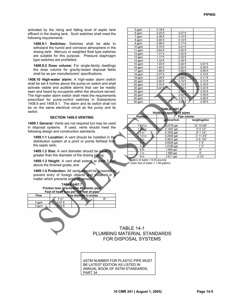
PIPING
10 CMR 241 ( August 1, 2005) Page 14-5
activated by the rising and falling level of septic tank effluent in the dosing tank. Such switches shall meet the following requirements:
1408.9.1 Switches: Switches shall be able to withstand the humid and corrosive atmosphere in the dosing tank. Mercury or weighted float type switches are suitable for this purpose. Pressure diaphragm type switches are prohibited.
1408.9.2 Dose volume: For single-family dwellings the dose volume for gravity-dosed disposal fields shall be as per manufacturers’ specifications.
1408.10 High-water alarm: A high-water alarm switch shall be set 4 inches above the pump-on switch and shall activate visible and audible alarms that can be readily seen and heard by occupants within the structure served. The high-water alarm switch shall meet the requirements prescribed for pump-control switches in Subsections 1408.9 and 1408.9.1. The alarm and its switch shall not be on the same electrical circuit as the pump and its switch.
SECTION 1409.0 VENTING
1409.1 General: Vents are not required but may be used in disposal systems. If used, vents should meet the following design and construction standards.
1409.1.1 Location: A vent should be installed in the distribution system at a point or points farthest from the septic tank;
1409.1.2 Size: A vent diameter should be equal to or greater than the diameter of the dosing piping;
1409.1.3 Height: A vent shall extend at least 3 feet above the finished grade; and
1409.1.4 Protection: All vents should be screened to prevent entry of foreign objects and installed in a matter which prevents entry of rainwater.
TABLE 1407.7 Friction loss in schedule 40 plastic pipe
Feet of head loss per 100 feet of pipe Flow Pipe diameter in inches
1 ½” 2” 3” 3 gpm 0.07 ft 4 gpm 0.12 ft
5 gpm 0.18 ft 6 gpm 0.25 ft 0.07 ft 7 gpm 0.36 ft 0.10 ft 8 gpm 0.46 ft 0.14 ft 9 gpm 0.58 ft 0.17 ft 10 gpm 0.70 ft 0.21 ft 11 gpm 0.84 ft 0.25 ft 12 gpm 1.01 ft 0.30 ft 13 gpm 1.17 ft 0.35 ft 14 gpm 1.33 ft 0.39 ft 15 gpm 1.45 ft 0.44 ft 0.07 ft 16 gpm 1.65 ft 0.50 ft 0.08 ft17 gpm 1.86 ft 0.56 ft 0.09 ft18 gpm 2.07 ft 0.62 ft 0.10 ft19 gpm 2.28 ft 0.68 ft 0.11 ft20 gpm 2.46 ft 0.74 ft 0.12 ft25 gpm 3.75 ft 1.10 ft 0.16 ft30 gpm 5.22 ft 1.54 ft 0.23 ft35 gpm 2.05 ft 0.30 ft 40 gpm 2.62 ft 0.39 ft 45 gpm 3.27 ft 0.48 ft 50 gpm 3.98 ft 0.58 ft
TABLE 1407.8
Holding capacity of pipes Diameter Pipe volume
gallons/foot length/gallon
1 1/4 in 0.0776 gal 12’ 10 5/8”1 1/2 in 0.1057 gal 9’ 5 1/2“
2 in 0.1632 gal 6’ 1 1/2“2 1/2 in 0.2549 gal 3’ 11 3/4”
3 in 0.3672 gal 2’ 8 3/4“4 in 0.6528 gal 1’ 6”5 in 1.0199 gal 1’ 0”6 in 1.469 gal 8”7 in 1.999 gal 6”8 in 2.611 gal 4 1/2”
1 gallon of water = 8.35 pounds 1 cubic foot of water = 7.48 gallons
TABLE 14-1
PLUMBING MATERIAL STANDARDS FOR DISPOSAL SYSTEMS
ASTM NUMBER FOR PLASTIC PIPE MUST BE LATEST EDITION AS LISTED IN ANNUAL BOOK OF ASTM STANDARDS, PART 34
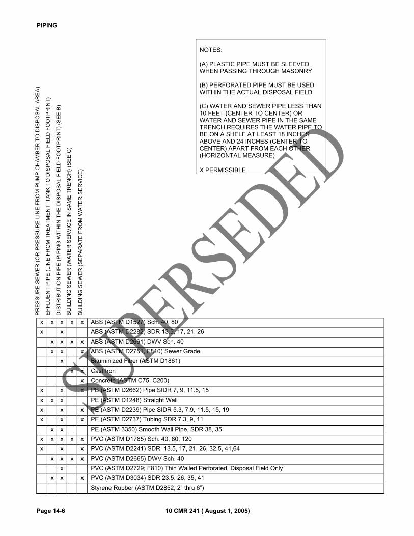
PIPING
Page 14-6 10 CMR 241 ( August 1, 2005)
NOTES: (A) PLASTIC PIPE MUST BE SLEEVED WHEN PASSING THROUGH MASONRY (B) PERFORATED PIPE MUST BE USED WITHIN THE ACTUAL DISPOSAL FIELD (C) WATER AND SEWER PIPE LESS THAN 10 FEET (CENTER TO CENTER) OR WATER AND SEWER PIPE IN THE SAME TRENCH REQUIRES THE WATER PIPE TO BE ON A SHELF AT LEAST 18 INCHES ABOVE AND 24 INCHES (CENTER TO CENTER) APART FROM EACH OTHER (HORIZONTAL MEASURE) X PERMISSIBLE�
x x x x x ABS (ASTM D1527) Sch. 40, 80
x x ABS (ASTM D2282) SDR 13.5, 17, 21, 26
x x x x ABS (ASTM D2661) DWV Sch. 40
x x x ABS (ASTM D2751, F810) Sewer Grade
x Bituminized Fiber (ASTM D1861)
x x Cast Iron
x Concrete (ASTM C75, C200)
x x x PB (ASTM D2662) Pipe SIDR 7, 9, 11.5, 15
x x x PE (ASTM D1248) Straight Wall
x x x PE (ASTM D2239) Pipe SIDR 5.3, 7,9, 11.5, 15, 19
x x x PE (ASTM D2737) Tubing SDR 7.3, 9, 11
x x PE (ASTM 3350) Smooth Wall Pipe, SDR 38, 35
x x x x x PVC (ASTM D1785) Sch. 40, 80, 120
x x x PVC (ASTM D2241) SDR 13.5, 17, 21, 26, 32.5, 41,64
x x x x PVC (ASTM D2665) DWV Sch. 40
x PVC (ASTM D2729; F810) Thin Walled Perforated, Disposal Field Only
x x x PVC (ASTM D3034) SDR 23.5, 26, 35, 41
Styrene Rubber (ASTM D2852, 2” thru 6”)
PR
ES
SU
RE
SE
WE
R (
OR
PR
ES
SU
RE
LIN
E F
RO
M P
UM
P C
HA
MB
ER
TO
DIS
PO
SA
L A
RE
A)
EF
FL
UE
NT
PIP
E (
LIN
E F
RO
M T
RE
AT
ME
NT
T
AN
K T
O D
ISP
OS
AL
FIE
LD
FO
OT
PR
INT
)
DIS
TR
IBU
TIO
N P
IPE
(P
IPIN
G W
ITH
IN T
HE
DIS
PO
SA
L F
IEL
D F
OO
TP
RIN
T)
(SE
E B
)
BU
ILD
ING
SE
WE
R (
WA
TE
R S
ER
VIC
E I
N S
AM
E T
RE
NC
H)
(SE
E C
)
BU
ILD
ING
SE
WE
R (
SE
PA
RA
TE
FR
OM
WA
TE
R S
ER
VIC
E)
10 CMR 241 ( August 1, 2005) Page 15 -1
CHAPTER 15
WETLANDS
SECTION 1500.0 GENERAL
1500.1 Scope: This Chapter governs the installation of disposal systems in wetlands and in areas adjacent to wetlands. Work in these areas must comply with any other pertinent regulations such as the Corps of Engineers, Environmental Protection Agency, Department of Environmental Protection, or local ordinances (see Section 1500.4).
1500.2 Intent: The filling of or the alteration of wetlands for any purpose, including activities associated with the installation of systems, is prohibited unless such filling or alteration is specifically approved by all relevant agencies. This includes adjacent activities which may cause material to wash into the wetland.
1500.3 Wetland jurisdiction: The Army Corps of Engineers makes jurisdictional determinations and issues wetland permits for filling, dredging, and other construction in certain wetlands under Section 10 of the Rivers and Harbors Act of 1899. The Army Corps of Engineers provides the same function under Section 404 of the Clean Waters Act for all other wetlands, with program oversight by the U.S. Environmental Protection Agency (EPA). With the combination of these two acts, all wetlands, regardless of size, are regulated by EPA and the Army Corps of Engineers. The Maine Department of Environmental Protection (DEP) regulates activities in, or adjacent to, coastal or freshwater wetlands, as defined in Chapter 2 under the Natural Resources Protection Act, Title 38 M.R.S.A. §480-A et seq.
1500.4 Permit by Rule: The installation or repair of a system does not require a Natural Resources Protection Act permit from the Department of Environmental Protection provided all Sections of this code are met. The requirements contained in Section 1504.0 of this code are designed to meet the same requirements contained in DEP’s Permit by Rule program for soil disturbance adjacent to or within a protected natural resource.
SECTION 1501.0 WETLAND DELINEATION
1501.1 Individuals who may delineate wetlands: Although certification is presently not required to perform wetland boundary delineation, people who do so should have sufficient scientific expertise to perform such delineation.
1501.2 Wetlands suspected to be present: When site evaluators suspect wetlands may affect the proposed location of a system they have designed, they should advise their clients that:
1501.2.1 Wetland alteration permit may be necessary: Wetlands may be involved and that a wetlands alteration permit may be necessary;
1501.2.2 System design is preliminary: The system design and location is preliminary as it is
dependent on applicable wetland rules and setbacks; and
1501.2.3 Wetland delineation is needed: The client shall hire an expert to identify and delineate the wetland boundary (if the site evaluator does not have sufficient scientific expertise to do so.)
1501.3 Wetlands present: If a wetland is present, the applicant should contact the Maine Department of Environmental Protection and the U.S. Army Corps of Engineers regarding the possible need for State and Federal Wetland Alteration Permits.
SECTION 1502.0 DISPOSAL SYSTEMS INSTALLED WITHIN WETLAND
1502.1 First time systems: First time systems may not be installed within a wetland. First time systems installed outside the wetland boundary, but which require fill material extensions that are adjacent to or cross into coastal or special freshwater wetlands, may be allowed provided that permits are obtained by the property owner from applicable regulatory agencies and no reasonable alternative exists.
1502.2 Replacement systems: Replacement systems may be installed partially or wholly within wetlands, provided that: no reasonable alternative exists; the amount of fill material placed in the wetland is minimized to the fullest extent possible.
SECTION 1503.0 SOIL DISTURBANCE WITHIN 100 FEET OF WATER BODIES AND WETLANDS
1503.1 Minimum standards: All ground disturbance occurring within 100 feet of a coastal wetland, freshwater wetland, great pond, or water course shall comply with the minimum standards set forth in Section 1504.0.
1503.2 If unable to meet minimum standards: Activities that cannot meet all the minimum standards set forth in this chapter are subject to permit requirements under the Natural Resources Protection Act administered by the Maine Department of Environmental Protection.
SECTION 1504.0 WORK ADJACENT TO SPECIAL WETLANDS AND WATER BODIES
1504.1 Runoff prevention: In order to prevent runoff which may carry sediment from the disturbance activity from directly entering water bodies, the standards in this section apply to all ground disturbance occurring within 100 feet of a coastal wetland, special freshwater wetlands, great ponds or major waterbodies/courses.
1504.2 Permits required: Soil disturbance activities within 100 feet of a coastal wetland, special freshwater wetlands, great ponds, or water courses that cannot meet all of the following standards are subject to permit requirements under the Natural Resource Protection Act administered by the Maine Department of Environmental Protection. Compliance with the following sections is considered a permit by rule:
WETLANDS
Page 15-2 10 CMR 241 ( August 1, 2005)
1504.2.1 Sites with slopes of less than 20%: Where sustained slopes are less than 20%, a 25-foot setback shall be maintained between the normal high water line or upland edge of a coastal wetland, special freshwater wetlands, great ponds or major waterbodies/courses (whichever is more restrictive) and any soil disturbance activity; and
1504.2.2 Sites with slopes exceeding 20%: Where sustained slopes exceed 20%, a 100-foot setback shall be maintained between the normal high water line or upland edge of the coastal wetland, special freshwater wetlands, great ponds, or major waterbodies/courses (whichever is more restrictive) and any soil disturbance activity; and
1504.2.3 Runoff diverted: Upland surface water runoff shall be diverted around the soil disturbance activity.
1504.2.4 Replacement systems: The setback requirements for removal, replacement or maintenance of wastewater disposal systems, authorized by this code, can be waived when no practical alternative exists and the LPI agrees.
1504.2.5 Buffers with vegetation: Existing vegetation within the 25 foot setback zone shall remain undisturbed except when removal is required for the maintenance, repair or installation of a replacement system.
1504.2.6 Wetland disturbance: Wetland vegetation shall not be destroyed or permanently removed, if at all possible. If wetland vegetation shall be disturbed during the project, it shall be reestablished immediately upon completion of the work and shall be maintained. This standard shall not apply to fill or disposal areas required for replacement of wastewater disposal systems.
1504.2.7 Erosion control barriers: Prior to the start of a soil disturbance activity, erosion control measures such as staked hay bales, or silt fence shall be properly installed and adequately maintained for the duration of the project, to prevent the wash of materials into the resource.
1504.2.8 Time limit: All soil disturbance activities shall start as soon as practical.
1504.2.9 Site stabilization: Disturbed soil shall be stabilized as soon as practical, upon activity completion.
1504.2.10 Additional: In addition to placement of riprap, sod, erosion control blankets or mulch, additional steps shall be taken where necessary, in order to prevent sedimentation of the water. Evidence of sedimentation includes visible gully erosion, discoloration of water by suspended particles and slumping of banks. Silt fences, staked hay bales and other sedimentation control measures, where planned for, shall be in place prior to commencement of work, but shall also be installed whenever necessary due to sedimentation.
1504.2.11 Duration of temporary erosion control: Mulch or other temporary erosion control measures shall be maintained until the site is permanently stabilized with vegetation or other permanent control measures.
Note: Erosion and sedimentation control measures should comply with U.S.D.A., Natural Resource Conservation Service and Soil and Water Conservation District specifications.
10 CMR 241 ( August 1, 2005) Page 16 -1
CHAPTER 16
DISPOSAL FIELDS ON VERY PERMEABLE SITES IN THE SHORELAND ZONE OF MAJOR WATERBODIES/COURSES
SECTION 1600.0 GENERAL
1600.1 Scope: This Chapter governs the installation of lined disposal fields on very permeable sites in the shoreland zone of major waterbodies/courses.
1600.2 Intent: The intent of these provisions is to provide better phosphorous retention on sites with extremely coarse soil horizons by replacing the extremely coarse soils below and around the disposal field when the site is excavated into the very coarse sub-surface soils. Note: When a stone disposal bed or proprietary devices are placed in or above the A or Ap horizon of the original soil so that a minimum of 12” of soil material, which is as fine or finer than backfill material described in Section 804.2, exists between the coarse horizon and the bottom of the disposal area, no liner is required.
1600.3 Very permeable sites: For the purposes of this Chapter, sites with Soil Profile 6 soils are considered to be very permeable.
SECTION 1601.0 LINED DISPOSAL FIELDS
1601.1 Construction: Lined disposal fields shall be installed as follows:
1601.1.1 Area to be excavated: An excavation shall be made to a minimum depth of 12 inches below the elevation of the bottom of the disposal field. This shall extend throughout the entire area to be occupied by the disposal field and beyond the perimeter of the disposal field a minimum of 1 foot in all directions;
1601.1.2 Backfill material: The excavation shall be backfilled with material meeting the requirements of Subsection 804.2 which constitutes the disposal field liner for the purposes of this Chapter.
1601.1.3 Liner: The liner shall extend a minimum of 12 inches beyond the foot print of the disposal field stone or proprietary devices.
1601.1.4: Backfill material shall be spread and compacted in layers of not more than 12 inches in thickness.
SECTION 1602.0 DISPOSAL FIELD
1602.1 Requirements: The installation of the disposal field and distribution network shall comply with Chapters 6, 8 and Chapter 14. The disposal field shall be sized using a minimum hydraulic loading rate for a medium system (2.6 sq. ft./gpd).

DISPOSAL FIELDS ON VERY PERMEABLE SITES IN THE SHORELAND ZONE OF MAJOR WATERBODIES/COURSES
Page 16-2 10 CMR 241 ( August 1, 2005)
10 CMR 241 ( August 1, 2005) Page 17 -1
CHAPTER 17
ALTERATION, REPAIR AND EXPANSION OF EXISTING DISPOSAL SYSTEMS
SECTION 1700.0 GENERAL
1700.1 Scope: This Chapter governs the alteration, repair or expansion of existing systems.
SECTION 1701.0 ALTERATIONS OR REPAIRS OF EXISTING DISPOSAL SYSTEMS
1701.1 General: Alterations or repairs made to existing disposal systems, excluding those required for an expansion or change in use may be approved by the local plumbing inspector provided that all requirements of this Section are met.
1701.1.1 Application for alteration or repair of an existing disposal system: Any modification, repair or alteration of the disposal field, other than the addition of fill, requires the determination of the Local Plumbing Inspector as to whether or not a permit is required. If a permit is required, such modification, repair or alteration shall be as prescribed by a Maine Licensed Professional Engineer or a Maine Licensed Site Evaluator and shall be considered a disposal field for permitting purposes.
1701.1.2 Conformity with this code: Approved alterations or repairs shall be limited to those systems that are in compliance with this code or that will come into compliance with this code as a result of the alteration or repair.
1701.2 Existing overboard discharge: Any structure(s) licensed to discharge treated or untreated wastewater or any property to which a valid license has been issued to discharge wastewater to the waters of the state may install a disposal system using replacement system criteria.
SECTION 1702.0 EXPANSION OR CHANGE IN USE OF EXISTING STRUCTURES
1702.1 General: Any expansion or change in use of a structure which results in an increase in design flow and which requires larger disposal system components than are present in the existing disposal system must first obtain a permit in accordance with this section and any municipal ordinances governing subsurface wastewater disposal systems. Expansions of a structure, such as a porch, living room or sun room, which do not increase the design flow are exempt from the requirements of this section.
1702.2 Minor expansion: The initial expansion of a single family home after May 1, 1995 by the addition of no more than one bedroom, or, if the home is served by pressurized water, the replacement of an alternative toilet by a conventional water closet. For other structures, a minor expansion is the initial expansion since May 1, 1995, which results in an increase in design flow of 10 percent or more up to 25 percent.
1702.3 Major expansion: Any expansion which results in a greater design flow and larger disposal system
components than allowed for minor expansions, the introduction of pressurized water to a structure formerly served by hand pumped or hand carried water, the addition of a second dwelling unit to the property, any second or subsequent minor expansion of a structure since May 1, 1995, or an expansion for a nonresidential use or structure resulting in an increase of more than 25 percent of the existing design flow.
SECTION 1703.0 EXPANSIONS OUTSIDE OF THE SHORELAND ZONE OF MAJOR
WATERBODIES/COURSES
1703.1 Minor expansions design criteria: Minor expanded disposal systems shall meet replacement system design criteria as set forth in. Tables 600.3 and 700.3
1703.2 Minor expanded systems located outside of the shoreland zone of major waterbodies/courses not upgraded at the time of expansion: If a minor expanded system is located outside of the shoreland zone of a major waterbody/course, the owner may elect to not install the expanded disposal system at the time of expansion, provided the existing disposal system is functioning properly, by utilizing the following procedure. This procedure must be met prior to the expansion:
1703.3.1 Application (HHE-200): The applicant shall provide a completed application to the local plumbing inspector demonstrating that if the existing disposal system malfunctions in the future, it can be replaced or enlarged in accordance with this code and any municipal ordinances that apply to systems. The application shall show the location of the existing system, the replacement or enlarged system, lot lines and all wells within applicable setback distances.
1703.3.2 Registry of deeds: A copy of the documentation required in 1703.3.1 shall be recorded in the appropriate registry of deeds. The Department shall prescribe the form of the notice to be recorded in the County Registry of Deeds.
1703.3.3 Notify abutters: The person seeking to expand a structure shall send a copy of the notice of documentation, by certified mail, return receipt requested, to all owners of abutting lots.
1703.3.4 Protection of future installation: After the documentation required in 1703.3.1 has been recorded in the appropriate registry of deeds and all abutters have been notified, no owner of abutting property may install a well in a location that would prevent the installation of the expanded disposal system. The owner of the lot on which the expanded disposal system is to
ALTERATION, REPLACEMENT AND EXPANSION OF EXISTING DISPOSAL SYSTEMS
Page 17-2 10 CMR 241 ( August 1, 2005)
be installed may not erect any structure on the proposed site of the expanded disposal system or conduct any activity that would prevent the use of the designated site for the expanded disposal system.
1703.4 Major expanded systems located outside the shoreland zone of major waterbodies/courses: Major expanded disposal systems shall meet first time system design criteria as set forth in this code and must be installed prior to the expansion, except as otherwise authorized in this section.
1703.4.1 Reduction in design criteria for major expansions outside of the shoreland zone of major waterbodies/courses for single family dwellings: If a site evaluator determines that a major expanded disposal system for a single family dwelling can not be installed in accordance with first time system criteria, there is no practical alternative and reductions are minimized, the local plumbing inspector may approve the reduced criteria as set forth in Tables 600.3 and 700.3.
SECTION 1704.0 EXPANSIONS INSIDE OF THE SHORELAND ZONE OF MAJOR
WATERBODIES/COURSES
1704.1 Minor expanded systems located within the shoreland zone of major waterbodies/courses: Minor expanded systems located within the shoreland zone of major waterbodies/courses must be installed prior to the expansion.
1704.1.1 Reduced criteria for minor expanded systems located within the shoreland zone of major waterbodies/courses: For minor expanded disposal systems located within the shoreland zone of major waterbodies/courses, the local plumbing inspector may authorize the reduced criteria as set forth in Tables 600.4 and 700.4.
1704.2 Major expanded systems located within the shoreland zone of major waterbodies/courses: Major expanded disposal systems shall meet first time system design criteria as set forth in this code and must be installed prior to the expansion.
10 CMR 241 ( August 1, 2005) Page 18-1
CHAPTER 18
EXPERIMENTAL TECHNOLOGY AND PRODUCT REGISTRATION REQUESTS
SECTION 1800.0 GENERAL
1800.1 Scope: This Chapter governs applications for new or experimental technology and requests for product registration.
1800.2 Intent: This Chapter provides a procedure to review the installation, operation, and long term requests for monitoring of experimental technologies and requests for new product registration.
1800.3 Application: Applications for new or experimental technology and requests for product registration shall be accompanied by an application form as determined by the Division.
SECTION 1801.0 REQUIREMENTS FOR NEW OR EXPERIMENTAL TECHNOLOGY
1801.1 General: Any permit issued to allow an experimental technology system shall require, as a condition of issuance, the establishment of a monitoring program by which system performance can be demonstrated. At a minimum, all experimental technology systems shall be capable of operating at the same degree of efficacy and reliability as any authorized alternative appropriate for the site. Any variance issued will require that the system be altered if such efficacy and reliability are not obtained, in order to bring performance up to standard, or, if such alteration is not feasible, that the system shall be abandoned.
1801.2 Applicants shall demonstrate: Requests for the installation of experimental technology systems may be granted by the Department if it is demonstrated that the conditions set forth in this Section can be met.
1801.3 Backup design: An authorized design can be installed on the property for which an experimental technology system is proposed. The backup system design shall be recorded with the county registry of deeds;
1801.4 Meets the intent of this code: The proposal is designed to protect public health, prevent the creation of any nuisance, and prevent environmental pollution to the same extent as the authorized system approved for the property;
1801.5 Sound engineering principles: The proposed design is shown to be based on sound engineering principles and can be expected to provide the same level of protection to public health and the environment as offered by the authorized system that could be installed on the property; and
1801.6 System performance: If the system does not perform so that it meets the purposes of this code, the applicant (or current owner) will expeditiously abandon the experimental system and install the backup system meeting all the requirements of this code.
1801.7 Approval: There are three (3) levels of approval for new or experimental technology: Pilot, Provisional,
and General Use. All Pilot and Provisional new or experimental technology system designs shall be approved by the Maine Department of Health and Human Services, Maine Center for Disease Control and Prevention, Division of Environmental Health (Division) prior to installation.
1801.7.1 Pilot approval: Pilot approval allows an applicant to demonstrate the general ability of a proposed new or experimental technology to treat wastewater as defined in the Rules. No less than 10 installations of a specific new or experimental technology shall be granted Pilot system approval by the Division. Pilot approvals shall be limited to sites which do not otherwise require any variance or waiver to the Rules. On no less than a bi-weekly basis for a period of not less than six months, and once per month for at least an additional six months, the applicant shall test the influent and effluent of each installed new or experimental technology system for the following parameters: five day Biochemical Oxygen Demand (BOD5), Total Suspended Solids (TSS), Nitrate Nitrogen (N03), Nitrite Nitrogen (NO2), Total Kjeldahl Nitrogen (TKN), Ammonia Nitrogen (NH4), and coliform bacteria. The results of these tests shall be submitted to the Division on no less than a quarterly basis. Historic data from other jurisdictions may be submitted, if available. If such data are satisfactory, the applicant may bypass Pilot approval and proceed to Provisional status.
1801.7.2 Provisional approval: Provisional approval allows an applicant to demonstrate ability of a proposed new or experimental technology to operate under a broader range of site conditions and to provide a larger number of data sources for such demonstration. No less than 25 installations of a specific new or experimental technology shall be granted Provisional system approval by the Division, of which 10 may be Pilot systems previously approved by the Division. Provisional approvals shall not be granted until the Pilot systems have been in operation for at least one year. Provisional approval installations may include sites which require a variance or waiver to the Rules, with the provision that such variances or waivers are also subject to the standard variance requirements of the Rules, i.e., a passing point score for soils related variances, etc. On no less than a monthly basis for a period of not less than one year, the applicant shall test the influent and effluent of each installed new or experimental technology system for the following parameters: five day Biochemical Oxygen Demand (BOD5), Total Suspended Solids (TSS), Nitrate Nitrogen (N03), and coliform bacteria. The results of these tests shall be submitted to the Division on no less than a semi-annual basis. Existing data from other jurisdictions may be submitted, if available. If such data are satisfactory, the applicant may bypass
EXPERIMENTAL TECHNOLOGY AND PRODUCT APPROVAL REQUESTS
Page 18-2 10 CMR 241 ( August 1, 2005)
Provisional approval and proceed to General Use status.
1801.7.3 General Use approval: To receive General Use approval for an new or experimental technology, the applicant shall demonstrate that the 50 systems installed under Provisional approval have operated as designed and intended. Upon such demonstration, the provisionally approved new or experimental technology under consideration shall be granted written General Use status approval for use in Maine, and shall be included in the next revision of the Rules.
1801.7.4 Failure to Perform: In the event that a new or experimental technology fails to perform as claimed by the applicant, use of the new or experimental technology in Maine, including all installations pursuant to Section 1801.7 of this code, shall cease. Use of the new or experimental technology shall not resume until the applicant and the Division have reached a mutually acceptable agreement for resolving the failure to perform as claimed.
SECTION 1802.0 REQUIREMENTS FOR PRODUCT REGISTRATION
1802.1 General: Any manufacturer or distributor submitting new products (including, but not limited to, remedial products, processes or devices, disposal system components, pre-filters or proprietary disposal devices) to the Department for code approval and registration shall demonstrate that the conditions set forth in this Section are met.
1802.2 Meets the intent of this code: The product is designed to protect public health, prevent the creation of any nuisance, and prevent environmental pollution to the same extent as comparable products presently authorized by the Department for use in this code;
1802.3 Sound engineering principles: The product is based on sound engineering principles and can be expected to provide the same level of protection to public health and the environment as offered by the authorized products presently authorized by the Department for use in this code. Sound engineering principles may be demonstrated by submitting a letter to the Department from a) a certifying organization, such as the Building Officials and Code Administrators (BOCA), or other suitable organization stating their approval of the product, or b) the American Society for Testing and Materials (ASTM) indicating the requested product (used as indicated in the request) meets the ASTM standard as specifically listed in the appropriate section of any nationally recognized code, such as BOCA or equal.
1802.4 Registration: There are three (3) levels of approval for product registration: Pilot, Provisional, and General Use. All Pilot and Provisional product registration installations shall be approved by the Maine Department of Health and Human Services, Maine Center for Disease Control and Prevention, Division of Environmental Health (Division) prior to installation.
1802.4.1 Pilot approval: Pilot approval allows an applicant to demonstrate the general ability of a proposed product to treat wastewater as defined in the Rules, or perform other functions as claimed by the applicant. No less than 10 installations of a specific product registration shall be granted Pilot approval by the Division. Pilot approvals shall be limited to sites which do not otherwise require any variance or waiver to the Rules, if wastewater treatment is claimed by the applicant. If wastewater treatment is claimed by the applicant, on no less than a bi-weekly basis for a period of not less than six months, and once per month for at least an additional six months, the applicant shall test the influent and effluent of each installed product registration for the following parameters: five day Biochemical Oxygen Demand (BOD5), Total Suspended Solids (TSS), Nitrate Nitrogen (N03), Nitrite Nitrogen (NO2), Total Kjeldahl Nitrogen (TKN), Ammonia Nitrogen (NH4), and coliform bacteria. The results of these tests shall be submitted to the Division on no less than a quarterly basis. Historic data from other jurisdictions may be submitted, if available. If such data are satisfactory, the applicant may bypass Pilot approval and proceed to Provisional status.
1802.4.2 Provisional approval: Provisional approval allows an applicant to demonstrate ability of a proposed product to operate under a broader range of site conditions and to provide a larger number of data sources for such demonstration. No less than 25 installations of a specific new or experimental technology shall be granted Provisional system approval by the Division, of which 10 may be Pilot systems previously approved by the Division. Provisional product registrations shall not be granted until the Pilot installations have been in operation for at least one year, or if historic data is accepted by the Division. Provisional product registration installations may include sites which require a variance or waiver to the Rules, with the provision that such variances or waivers are also subject to the standard variance requirements of the Rules, i.e., a passing point score for soils related variances, etc. If wastewater treatment is claimed by the applicant , on no less than a monthly basis for a period of not less than one year, the applicant shall test the influent and effluent of each installed provisionally approved product for the following parameters: five day Biochemical Oxygen Demand (BOD5), Total Suspended Solids (TSS), Nitrate Nitrogen (N03), and coliform bacteria. The results of these tests shall be submitted to the Division on no less than a semi-annual basis. Existing data from other jurisdictions may be submitted, if available. If such data are satisfactory, the applicant may bypass Provisional approval and proceed to General Use status.
1802.4.3 General Use approval: To receive General Use approval for a product registration, the applicant shall demonstrate that the 50 installations allowed under Provisional approval have operated as designed and intended. Upon such demonstration,
EXPERIMENTAL TECHNOLOGY AND PRODUCT APPROVAL REQUESTS
10 CMR 241 ( August 1, 2005) Page 18-3
the provisionally approved product under consideration shall be granted written General Use status approval for use in Maine, and shall be included in the next revision of the Rules.
1802.4.4 Advanced Wastewater Treatment Units and Effluent Filters: Advanced treatment units for treatment of wastewater as defined in this code, and septic tank effluent filters which have been certified by the National Sanitation Foundation (NSF) or Canadian Standards Authority (CSA) shall be allowed for Provisional Use in Maine, upon submission of such certification to the Department.
1802.4.5 Other Criteria: The Department shall consider other relevant supporting data for product registrations on a case-by-case basis.
1802.4.6 Failure to Perform: In the event that a product fails to perform as claimed by the applicant, use of the product in Maine, including all installations pursuant to Section 1802.4 of this code, shall cease. Use of the product shall not resume until the applicant and the Division have reached a mutually acceptable agreement for resolving the failure to perform as claimed.

EXPERIMENTAL TECHNOLOGY AND PRODUCT APPROVAL REQUESTS
Page 18-4 10 CMR 241 ( August 1, 2005)
10 CMR 241 ( August 1, 2005) Page 19-1
CHAPTER 19
VARIANCES
SECTION 1900.0 GENERAL
1900.1 Scope: This Chapter governs the requests for: 1) all variances for replacement systems, and 2) variances for first-time systems.
1900.2 Procedure: The procedure for processing a variance request depends upon whether it is for a first time or replacement system variance request and whether or not it is within the limit of authority of the LPI for final disposition.
SECTION 1901.0 FIRST TIME SYSTEM VARIANCE REQUESTS - DEPARTMENT
1901.1 Requests for variance: Request for first time system variances shall include a completed application submitted to the Department by the applicant. The completed application shall be on a form prescribed by the Department, signed by the LPI and municipal officer(s) and accompanied by the appropriate application fee.
1901.2 Contents of applications: An application for a first time system variance shall include the following:
1901.2.1 Completed application for a disposal system permit: A completed application for a permit to install a system or part of a system. It shall include complete plans and specifications for the proposed system and other pertinent information as required on the HHE-200 and HHE-215 forms;
1901.2.2 Requirements that cannot be met: The application shall indicate the section(s) and/or provision(s) of the rules for which a variance is being requested;
1901.2.3 Basis for variance request: The reason(s) why the condition(s) set forth in the Rules cannot be met as well as justification for the variance request. Justification shall include a discussion of why the variance will not have an impact upon wastewater treatment including how additional measures may be used to offset reductions to conditions required by the rules;
1901.2.4 No conflict with local ordinances: For variances that fall under this Chapter the applicant shall provide statement(s) that the completed application has been reviewed and signed by the LPI and municipal officer(s) on the HHE-215 form indicating that the application is complete and does not conflict with local ordinances.
1901.2.5 Additional engineering or measures: If pretreatment or additional measures are being proposed the application shall show how the proposed system and measures meet applicable sections of the rules, including the pretreatment requirements found in Chapter 6.
19012.6 Other information: The Department may request additional information from the applicant for a
first time system variance request. If the applicant fails to provide additional information requested by the Department within 60 days of the request, the variance request will automatically be denied.
SECTION 1902.0 FIRST TIME SYSTEM VARIANCE REQUEST - MUNICIPALITY
1902.1 Municipal Review: This section authorizes the municipality to review and make a final disposition of a request for a First Time System-soil condition Variance through the Local Plumbing Inspector. The intent of this section is that all decisions regarding these First Time System Variances be made at the local level, with no requirement for Department review. However, if a municipality so chooses, it may request, in writing, that the Department make final decisions regarding these First Time System Variances. When so notified, the Department will review and make final disposition upon all First Time System Variance requests within a municipality’s jurisdiction.
1902.2 Evaluation: The plumbing inspector or Department will evaluate the merits of First Time System Variance requests based on the criteria set forth in this section.
1902.3 Soil conditions: For a site that does not comply with the minimum soil conditions in Table 600.2, the plumbing inspector or Department will use the criteria contained in Section 1906.0 and Table 1900.1 to evaluate the potential for a variance, except that sites with less than 12 inches of original soil over bedrock outside shoreland zoned areas of major waterbodies/courses or 15 inches within the shoreland zoned area of major waterbodies/courses and sites with less than 7 inches over hydraulically restrictive horizon or seasonal water table, in any location, will not be considered.
1902.4 Setbacks: For a site that does not comply with the minimum first time system setback distances in Chapter 7, variances shall be processed in accordance with Section 1901.0 (Department review required).
1903.0 REVIEW FEE
1903.1 Fee: A review fee, as prescribed in Table 110.2 or 110.3 shall be submitted to the municipality to defray the cost of review and processing a First Time System Variance request.
1904.0 CRITERIA USED BY THE PLUMBING INSPECTOR OR DEPARTMENT FOR APPROVAL
1904.1 General: An application, a First Time System Variance Form (HHE-215) and Review Fee shall be submitted to the LPI or Department demonstrating the criteria set forth in this section.
1904.2 Municipal ordinances: The Municipal Officers or Land Use Regulation Commission indicate by their
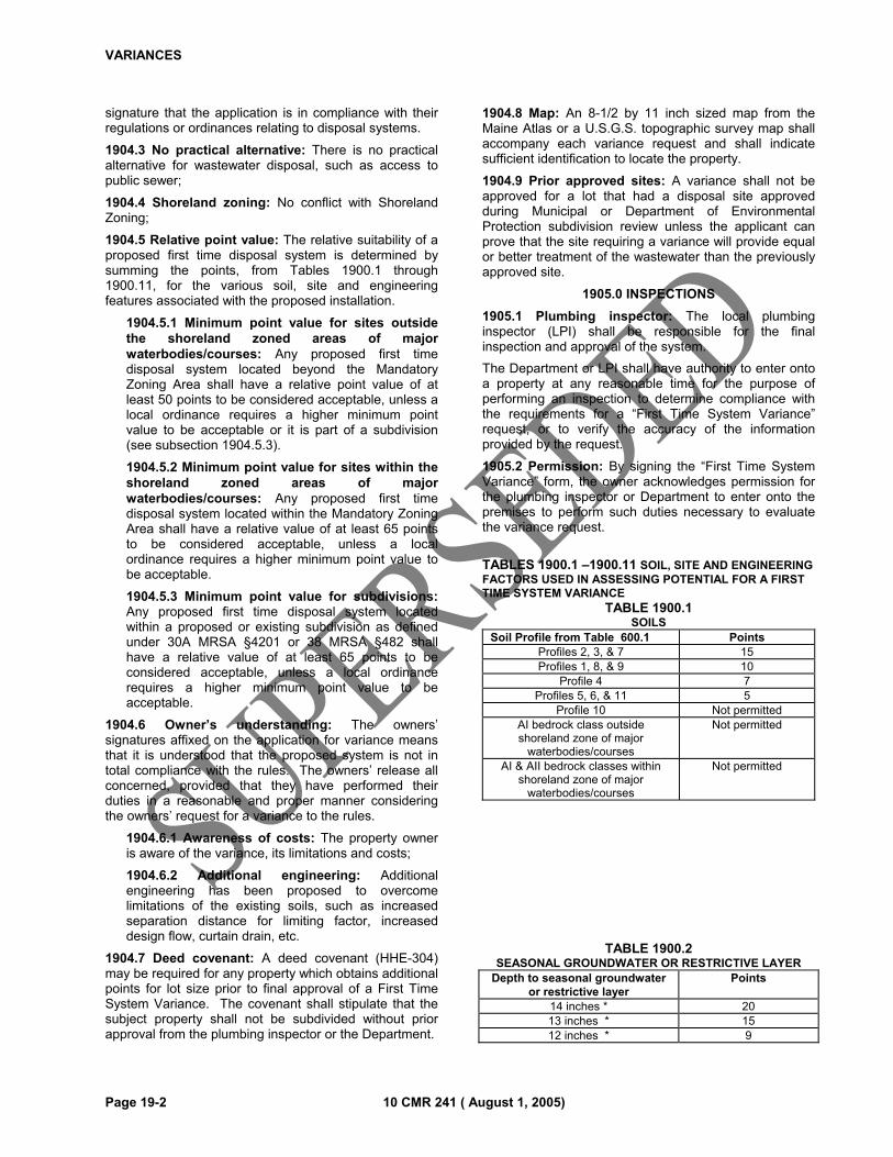
VARIANCES
Page 19-2 10 CMR 241 ( August 1, 2005)
signature that the application is in compliance with their regulations or ordinances relating to disposal systems.
1904.3 No practical alternative: There is no practical alternative for wastewater disposal, such as access to public sewer;
1904.4 Shoreland zoning: No conflict with Shoreland Zoning;
1904.5 Relative point value: The relative suitability of a proposed first time disposal system is determined by summing the points, from Tables 1900.1 through 1900.11, for the various soil, site and engineering features associated with the proposed installation.
1904.5.1 Minimum point value for sites outside the shoreland zoned areas of major waterbodies/courses: Any proposed first time disposal system located beyond the Mandatory Zoning Area shall have a relative point value of at least 50 points to be considered acceptable, unless a local ordinance requires a higher minimum point value to be acceptable or it is part of a subdivision (see subsection 1904.5.3).
1904.5.2 Minimum point value for sites within the shoreland zoned areas of major waterbodies/courses: Any proposed first time disposal system located within the Mandatory Zoning Area shall have a relative value of at least 65 points to be considered acceptable, unless a local ordinance requires a higher minimum point value to be acceptable.
1904.5.3 Minimum point value for subdivisions: Any proposed first time disposal system located within a proposed or existing subdivision as defined under 30A MRSA §4201 or 38 MRSA §482 shall have a relative value of at least 65 points to be considered acceptable, unless a local ordinance requires a higher minimum point value to be acceptable.
1904.6 Owner’s understanding: The owners’ signatures affixed on the application for variance means that it is understood that the proposed system is not in total compliance with the rules. The owners’ release all concerned, provided that they have performed their duties in a reasonable and proper manner considering the owners’ request for a variance to the rules.
1904.6.1 Awareness of costs: The property owner is aware of the variance, its limitations and costs;
1904.6.2 Additional engineering: Additional engineering has been proposed to overcome limitations of the existing soils, such as increased separation distance for limiting factor, increased design flow, curtain drain, etc.
1904.7 Deed covenant: A deed covenant (HHE-304) may be required for any property which obtains additional points for lot size prior to final approval of a First Time System Variance. The covenant shall stipulate that the subject property shall not be subdivided without prior approval from the plumbing inspector or the Department.
1904.8 Map: An 8-1/2 by 11 inch sized map from the Maine Atlas or a U.S.G.S. topographic survey map shall accompany each variance request and shall indicate sufficient identification to locate the property.
1904.9 Prior approved sites: A variance shall not be approved for a lot that had a disposal site approved during Municipal or Department of Environmental Protection subdivision review unless the applicant can prove that the site requiring a variance will provide equal or better treatment of the wastewater than the previously approved site.
1905.0 INSPECTIONS
1905.1 Plumbing inspector: The local plumbing inspector (LPI) shall be responsible for the final inspection and approval of the system.
The Department or LPI shall have authority to enter onto a property at any reasonable time for the purpose of performing an inspection to determine compliance with the requirements for a “First Time System Variance” request, or to verify the accuracy of the information provided by the request.
1905.2 Permission: By signing the “First Time System Variance” form, the owner acknowledges permission for the plumbing inspector or Department to enter onto the premises to perform such duties necessary to evaluate the variance request.
TABLES 1900.1 –1900.11 SOIL, SITE AND ENGINEERING FACTORS USED IN ASSESSING POTENTIAL FOR A FIRST TIME SYSTEM VARIANCE
TABLE 1900.1 SOILS
Soil Profile from Table 600.1 PointsProfiles 2, 3, & 7 15Profiles 1, 8, & 9 10
Profile 4 7Profiles 5, 6, & 11 5
Profile 10 Not permittedAI bedrock class outside shoreland zone of major
waterbodies/courses
Not permitted
AI & AII bedrock classes within shoreland zone of major
waterbodies/courses
Not permitted
TABLE 1900.2 SEASONAL GROUNDWATER OR RESTRICTIVE LAYER
Depth to seasonal groundwater or restrictive layer
Points
14 inches * 20 13 inches * 15 12 inches * 9
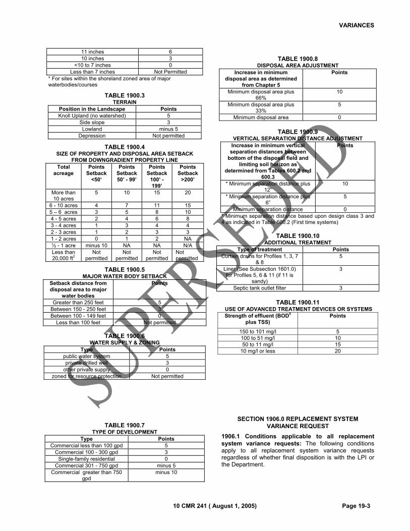
VARIANCES
10 CMR 241 ( August 1, 2005) Page 19-3
11 inches 6 10 inches 3
<10 to 7 inches 0 Less than 7 inches Not Permitted
* For sites within the shoreland zoned area of major waterbodies/courses
TABLE 1900.3 TERRAIN
Position in the Landscape Points Knoll Upland (no watershed) 5
Side slope 3 Lowland minus 5
Depression Not permitted
TABLE 1900.4 SIZE OF PROPERTY AND DISPOSAL AREA SETBACK
FROM DOWNGRADIENT PROPERTY LINE Total
acreage Points
Setback <50’
Points Setback 50’ - 99’
Points Setback
100’ - 199’
Points Setback
>200’
More than 10 acres
5 10 15 20
6 - 10 acres 4 7 11 15 5 – 6 acres 3 5 8 10 4 - 5 acres 2 4 6 8 3 - 4 acres 1 3 4 4 2 - 3 acres 1 2 3 3 1 - 2 acres 0 1 2 NA ½ - 1 acre minus 10 NA NA N/A Less than 20,000 ft2
Not permitted
Not permitted
Not permitted
Not permitted
TABLE 1900.5 MAJOR WATER BODY SETBACK
Setback distance from disposal area to major
water bodies
Points
Greater than 250 feet 5 Between 150 - 250 feet 3 Between 100 - 149 feet 0
Less than 100 feet Not permitted
TABLE 1900.6 WATER SUPPLY & ZONING
Type Points public water system 5 private drilled well 3
other private supply 0 zoned for resource protection Not permitted
TABLE 1900.7 TYPE OF DEVELOPMENT
Type Points Commercial less than 100 gpd 5
Commercial 100 - 300 gpd 3 Single-family residential 0
Commercial 301 - 750 gpd minus 5 Commercial greater than 750
gpd minus 10
TABLE 1900.8
DISPOSAL AREA ADJUSTMENT Increase in minimum
disposal area as determined from Chapter 5
Points
Minimum disposal area plus 66%
10
Minimum disposal area plus 33%
5
Minimum disposal area 0
TABLE 1900.9
VERTICAL SEPARATION DISTANCE ADJUSTMENT Increase in minimum vertical separation distances between
bottom of the disposal field and limiting soil horizon as
determined from Tables 600.2 and 600.3
Points
* Minimum separation distance plus 12“
10
* Minimum separation distance plus 6”
5
Minimum separation distance 0 * Minimum separation distance based upon design class 3 and 4 as indicated in Table 600.2 (First time systems)
TABLE 1900.10 ADDITIONAL TREATMENT
Type of treatment Points Curtain drains for Profiles 1, 3, 7
& 8 5
Liner (See Subsection 1601.0) for Profiles 5, 6 & 11 (if 11 is
sandy)
3
Septic tank outlet filter 3
TABLE 1900.11
USE OF ADVANCED TREATMENT DEVICES OR SYSTEMS Strength of effluent (BOD5
plus TSS) Points
150 to 101 mg/l 5 100 to 51 mg/l 10 50 to 11 mg/l 15
10 mg/l or less 20
SECTION 1906.0 REPLACEMENT SYSTEM VARIANCE REQUEST
1906.1 Conditions applicable to all replacement system variance requests: The following conditions apply to all replacement system variance requests regardless of whether final disposition is with the LPI or the Department.
VARIANCES
Page 19-4 10 CMR 241 ( August 1, 2005)
1906.1.1 Completed application for a disposal system permit: A completed application for a permit to install a system or part of a system shall be submitted to the LPI. It shall include complete plans and specifications for the proposed system and other pertinent information as required on the HHE-200 or HHE-233 (holding tank) forms.
1906.1.2 Requirement which cannot be met: The application shall indicate the section(s) and/or provision(s) of the rules for which a variance is being requested.
1906.1.3 Basis for a variance request: The reasons why the condition(s) set forth cannot be met.
1906.1.4 Application Review Fee: The replacement system application review fee, as indicated in Table 110.2 and Table 110.3 shall be submitted to the LPI.
1906.1.5 Minimum reduction necessary: The variance request is for the minimum reduction necessary to any requirement of the rules to accomplish the replacement system installation.
1906.1.6 No conflict with local ordinances: The request for a replacement system variance does not conflict with any local ordinance(s) or other rule(s) or statute(s).
1906.1.7 Meets definitions of replacement system: The replacement system variance request is to replace an existing system that was either in existence and functioning prior to July 1, 1974; or installed and permitted after July 1, 1974; or to replace an overboard discharge system.
1906.1.8 Additional engineering or measures: If pretreatment or other additional measures are being proposed, the application shall show how the proposed system and measures meet applicable sections of the rules, including Chapter 6.
1906.2 Replacement system variance requests which are within the limit of the LPI’s authority: Replacement System Variance Requests may be decided upon by the LPI, without Department review, if the following conditions are met:
1906.2.1 Standard conditions: All of the conditions of subsection 1906.1 are met:
1906.2.2 Setback reductions: Setback reductions are no greater than allowed in Table 700.3;
1906.2.3 Minimum soil conditions: Reductions in minimum soil conditions are no greater than allowed in Table 600.3;
1906.2.4 Fill extension slope: The fill extension slope is no greater than 3:1 or 33%;
1906.2.5 Wastewater strength: The BOD5 plus suspended solids content of the wastewater is no greater than that of normal domestic effluent.
1906.3 Replacement system variance requests which are beyond the limit of the LPI’s authority: Replacement System Variance Requests which are
beyond the LPI’s limit of authority must be submitted to the Department for review and disposition. They must meet the following conditions:
1906.3.1 Standard conditions: All of the conditions of subsection 1906.1 are met;
1906.3.2 LPI signature: The completed application, including HHE-204 or HHE-233 form, has been reviewed and signed by the LPI;
1906.3.3 Flexibility: The Department may be as flexible as is necessary to correct an existing, public health hazard.
SECTION 1907.0 DISPOSITION OF A VARIANCE BY THE DEPARTMENT
1907.1 General: The Department may approve a variance, deny it, or approve it with conditions. The disposition of the variance request will be in writing and state the specifications and conditions of any approval or the reasons for denial. The conditions may include deed covenants, inspections and mandatory installation of a holding tank if the system fails in the future.
SECTION 1908.0 TIME LIMIT
1908.1 General: Any disposal system variance issued after the effective date of this code shall become invalid if the system has not been installed in compliance with any conditions established with the variance within two years after issuance of the disposal system variance except that any malfunction shall be replaced at the earliest opportunity.
SECTION 1909.0 OWNER/APPLICANT’S UNDERSTANDING
1909.1 Applicant responsibilities: Approval of a variance under this Chapter shall not relieve the applicant of the responsibilities of complying with all other applicable federal, state and local laws, rules, or ordinances.
1909.2 Owner’s understanding: The owners’ signature affixed on the application for variance means that it is understood that the proposed system is not in total compliance with the rules. The owner releases all concerned, provided that they have performed their duties in a reasonable and proper manner, considering the owners’ request for a variance to the rules.
10 CMR 241 ( August 1, 2005) Page 20-1
CHAPTER 20
HOLDING TANKS
SECTION 2000.0 GENERAL
2000.1 Scope: This Chapter governs the approval and installation of holding tanks.
2000.2 Background: Holding tanks are designed to receive and hold the domestic wastewater leaving a structure. This wastewater, in turn, is pumped out and transported to a municipal treatment plant or to an approved land spreading site. The average person may generate 45 to 75 gallons of wastewater per day. Thus, a family of three can expect to fill a 1,500 gallon holding tank every 6 to 10 days. Holding tank pumping is costly and the holding tanks require continuous supervision on the part of the municipality to assure proper maintenance and pumping.
2000.3 General: The following applies to all holding tanks:
2000.3.1 Annual pumping required: Every holding tank shall be pumped at least once a year, providing the system has been used.
2000.3.2 Seasonal conversion not permitted: Holding tanks can not be used to satisfy the requirements for a Seasonal Conversion Permit under Title 30-A MRSA §4215 subsection 2 or a first time system located within the shoreland zoned area of major water courses, except as allowed by local ordinance.
2000.3.3 Water use monitoring: The plumbing inspector may require the installation of a water meter to monitor the flow to the holding tank.
2000.3.4 Reporting: The owner or agent for the owner of a holding tank shall retain for a period of three years the copies of the pumping records, water use records (if required) and the current agreement between the owner and tank pumper. A copy of these records shall be made available to the plumbing inspector upon his/her request.
2000.3.5 Holding tank specifications: Newly installed holding tanks shall be constructed of the same materials and to the same structural specifications as septic tanks, as specified in Chapter 9. They shall be either: a) of monolithic construction (effective May 1, 1999) below the top of the inlet to the holding tank, or b) sealed at the joint with a non-water soluble compound and all holding tanks shall have, at a minimum, an 18 inch diameter cleanout cover and a 13 by 17 inch inspection cover over the inlet.
2000.3.6 Installation: Holding tank shall be installed in accordance with Section 907.0.
2000.3.7 Setbacks: Shall meet the setback requirements for septic tanks (Tables 700.2, 700.3, 700.4).
2000.3.8 Alarm provisions: The holding tank shall have visual and audible alarm devices to assure the tank is always pumped before it is full.
2000.3.9 Number and size of holding tanks: The installation shall have a minimum capacity of at least seven times the daily flow but not less than 1,000 gallons. Multiple tanks shall be installed in series.
2000.3.10 Water conservation: The plumbing in the structure optimizes water conservation and all water closets meet or exceed ASME standard A112.19.2 (1.6 gallons per flush maximum).
2000.3.11 Discontinuance of Holding Tank: Any structure which utilizes a holding tank as a first time system shall be required to meet first time criteria for alternate means of subsurface wastewater disposal.
SECTION 2001.0 APPLICATION PROCEDURE
2001.1 Plumbing inspector approval: A holding tank application requires plumbing inspector approval.
2001.2 Application for a holding tank: A completed application for a holding tank (HHE-233) prepared by a Site Evaluator shall contain the following:
2001.2.1 Owner/Municipality agreement: A completed holding tank agreement (HHE-233) with the necessary owner/municipality statement is required.
SECTION 2002.0 REQUIREMENTS FOR APPROVAL OF ALL PERMANENT HOLDING TANKS
2002.1 LPI Approval: The plumbing inspector may approve the permanent use of a holding tank under the following conditions:
2002.1.1 Required by other regulation: A local ordinance of Private and Special Law requires that a holding tank be used for wastewater, or
2002.1.2 No practical alternative: Due to site conditions, lot configuration, or other constraints, the replacement, repair or alteration of an existing system, in full compliance with this code, is not achievable without the employment of extraordinary measures or extraordinary cost; and
2002.1.3 Public sewers not available: Public sewers and/or multi-user systems are, by practical means, not immediately available; and
2002.1.4 Water conservation: The plumbing in the structure will be modified for maximum water conservation, and all water closets shall meet or exceed ASME A112.19.2 for 1.6 gallons per flush.
2002.1.5 Deed Covenant: A deed covenant (HHE-300) shall be required for any residential structure served by a holding tank. As a minimum, the covenant shall include a statement that a holding tank is serving the structure for the disposal of human sewage and wastewater. The aforementioned
HOLDING TANKS
Page 20-2 10 CMR 241 ( August 1, 2005)
statement shall be a separate stand alone section or paragraph.
SECTION 2003.0 REPLACEMENT HOLDING TANKS
2003.1 LPI Approval: The plumbing inspector may approve the permanent use of a holding tank proposed by a site evaluator to replace a malfunctioning system or an alternative toilet.
2003.1.1 Malfunctioning system: The present system poses a threat or a potential threat to ground or surface water quality, to public health or safety, or to the environment; or,
2003.1.2 Alternative toilet replacement: An alternative toilet may be replaced by a flush toilet and holding tank if the existing structure is served by pressurized water and a legal gray wastewater system including treatment tank and disposal field.
2003.1.3 Application meets all criteria: The application meets all requirements of Section 2002.0.
SECTION 2004.0 FIRST TIME HOLDING TANKS WITH LOCAL ORDINANCE
2004.1 LPI Approval: The plumbing inspector may approve the permanent use of a holding tank for up to 2000 gpd as a first time system provided all the following requirements are met. Holding tanks for flows greater than 2000 gpd must be referred to the Department.
2004.1.1 Local ordinance: The municipality has a holding tank ordinance similar to the model ordinance in Appendix A, and has adopted this Section or an ordinance with similar or more strict provisions, a copy of which has been sent to the Department; and
2004.1.2 Application meets all criteria: The application meets all requirements of the ordinance and Section 2002.0.
SECTION 2005.0 FIRST TIME HOLDING TANKS WITHOUT LOCAL ORDINANCE
2005.1 Approval criteria: If the municipality has not adopted a holding tank ordinance under Chapter 20 and Appendix A, holding tanks for residential first time use are not allowed. The plumbing inspector may approve the permanent use of a holding tank for nonresidential structures provided all the following requirements are met:
2005.1.1 Use: The facility served must not require a license as an eating establishment from the Department.
2005.1.2 Design Flow: The flow shall not exceed 100 gallons per day or 500 gallons per week. Flows greater than 100 gallons per day or 500 gallons per week are to be referred to the Department.
2005.1.3 Application meets all criteria: The application meets all requirements of Section 2002.0.
SECTION 2006.0 TEMPORARY HOLDING TANKS
2006.1 Temporary use: As a temporary means of wastewater disposal during alteration or repair of an
existing system, the plumbing inspector may approve the use of a wastewater holding tank or a septic tank temporarily modified to serve as a holding tank for up to 2000 gpd. This use may not exceed 90 days. Temporary holding tanks do not require a holding tank application. 2006.2 Future public sewer connection: As a temporary means of wastewater collection, a local plumbing inspector may permit use of a holding tank by a facility for up to 365 days when physical connection to a public sewer is anticipated as stated in writing by the sanitary district. It is the responsibility of the sanitary district to insure that the holding tank is maintained in a sanitary manner. A holding tank application is not required for this instance. This permit may be extended for an additional 365 days if necessary.
10 CMR 241 ( August 1, 2005) Page 21-1
CHAPTER 21
MEANS OF APPEAL
SECTION 2100.0 GENERAL
2100.1 Scope: This Chapter governs the means of appealing a decision made by the Department pertaining to a variance to this code, a minimum lot size reduction request, or a code interpretation. Any appeal to a decision made by a Local Plumbing Inspector is made through the municipal officers.
2100.2 Appellant: For the purpose of this Chapter, the “appellant” is any party wishing to contest a decision by the Department on a variance request, Minimum Lot Size Law waiver request or code interpretation, or a person lawfully acting on the behalf of an appellant.
2100.3 Grounds for appeal: For the purpose of this Chapter, the grounds for appeal are limited to: (1) violation of the law or rules; (2) misapplication of the law or rules; or (3) a factual mistake that is likely to affect the decision.
2100.4 Aggrieved party: For the purpose of this Chapter, the appellant must specify in writing (1) the manner in which he or she is aggrieved; (2) the nature of harm he or she has suffered or is likely to suffer as a result of the Department’s decision; and (3) the relief sought.
2100.5 Settlement: Parties to a Formal Conference or a Formal Administrative Hearing may negotiate a mutually acceptable settlement at any point during the proceedings.
2100.6 Stopping Work: A formal, written request for a Formal Conference or Formal Administrative Hearing shall be cause for the Local Plumbing Inspector (LPI) to be notified by the Department to issue a Stop Work Order pending completion of the review process.
SECTION 2101.0 NOTICE
2101.1 General: The Department shall inform the appellant and any entitled abutters, in writing, of its intention to grant, deny, terminate, or suspend a variance or waiver issued pursuant to this code or code interpretation.
2101.2 Written Decision: Granting or denial of a variance, waiver or the issuance of a code interpretation shall be provided in writing.
SECTION 2102.0 APPEAL PROCEDURE
2102.1 General: The appeal procedure shall consist of three (3) levels of appeals. It shall proceed in the following sequence:
2102.1.1 Step 1: A formal conference;
2102.1.2 Step 2: A formal administrative hearing; and
2102.1.3 Step 3: A judicial review.
SECTION 2103.0 APPEAL FEES
2103.1 General: An administrative appeal fee for a formal conference or a formal administrative hearing shall be levied as follows:
2103.1.1 Formal conference fee: An administrative appeal fee of $50.00.
2103.1.2 Formal administrative hearing fee: An administrative appeal fee of $75.00; and
2103.1.3 Judicial review fee: Subject to judicial procedures.
2103.2 Exemption: Individuals who can prove they are qualified to receive public benefits, such as Medicaid or AFDC are exempt from the administrative fees listed in 2103.1.1, “Formal conference fee”, and 2103.1.2, “Formal administrative hearing fee”. Procedures for demonstrating eligibility shall be consistent with those utilized in the benefit programs. The Commissioner of the Department of Health and Human Services may grant a fee exemption when it is determined to be appropriate.
2103.3 Administrative Fee Payment: A check for the appropriate amount shall be made out for the “Treasurer of State”. The check shall be sent to: Department of Health and Human Services, Division of Environmental Health, Wastewater and Plumbing Control Program. Payment shall be made prior to scheduling any Formal Conference or Administrative Hearing.
SECTION 2104.0 REQUEST FOR FORMAL CONFERENCE
2104.1 General: To appeal a decision of the Department, the appellant shall submit a written request for a formal conference. The appellant shall submit the request to the Department within thirty (30) days of the date of the Department’s written decision. The request shall include the following:
2104.1.1 Intention: The intended/requested appeal action; and
2104.1.2 Reason(s): The reasons that support the intended action, including: (1) violation of the law or rules; (2) misapplication of the law or rules; and/or (3) factual mistake that is likely to affect the decision.
2104.1.3 Aggrieved party: A written statement which shall specify the person or persons seeking a formal conference and the manner in which they are aggrieved as specified under Section 2100.4.
2104.2 Limiting the issues: Before the formal conference, the appellant shall raise all issues upon which he or she appeals the decision.
SECTION 2105.0 FORMAL CONFERENCE
MEANS OF APPEAL
Page 21-2 10 CMR 241 ( August 1, 2005)
2105.1 Intent: This section sets forth the procedures to be used for formal conferences.
2105.2 Written request: The written request must be mailed to:
Director, Division of Environmental Health 11 State House Station Augusta, Maine 04333-0011
2105.3 Scheduling the conference: As soon as practicable, the Department shall notify the appellant of the date, time, and place of the formal conference.
2105.4 Conference officer: The formal conference will be conducted by the Director of the Division of Environmental Health, or his or her designee.
2105.5 Conference Location: The Conference Officer shall schedule a conference in Augusta, Maine.
2105.6 Representation: At the formal conference, the appellant may be represented by legal counsel or any other representative on his or her behalf. The applicant and/or owner of the property for which the appeal has been filed may attend the formal conference and may be represented by legal counsel or any other representative on his or her behalf.
2105.7 Disputed issues: The appellant or representative shall raise all issues about which he or she disagrees with the Department’s decision. He or she may present new evidence or information or otherwise present arguments in response to the Department’s intended action. Failure to raise any issues at the formal conference shall be deemed a waiver of any appeal rights on those issues.
2105.8 Written decision: Following the formal conference, the Director shall issue a written decision to the appellant which shall affirm, modify, or revoke the initial and intended decision of the Department.
SECTION 2106.0 FORMAL ADMINISTRATIVE HEARING
2106.1 Intent: This section sets forth the procedures to be used for formal administrative hearings.
2106.2 Hearing request: If the appellant is dissatisfied with the written decision of the formal conference, he or she may appeal that decision by submitting a written “Request for Administrative Hearing” within thirty (30) days of the date of the written formal conference decision to:
Chief Hearings Officer Office of Administrative Hearing 11 State House Station Augusta, Maine 04333-0011
2106.2.1 Request: The request to the Office of Administrative Hearings shall be accompanied by a copy of the fair hearing report.
2106.2.2 No Request: If the appellant does not request the hearing within the thirty (30) day time period absent good cause, the hearing may be denied by the Office of Administrative Hearings.
2106.2.3 Disclosure: If the appellant does not set forth the issues aggrieved, the request for hearing may be denied by the Office of Administrative Hearings.
2106.3 Issues on appeal: The request shall state the specific issues being appealed.
2106.4 Hearing officer: An impartial hearing officer shall conduct the administrative hearing.
2106.5 Representation: At the hearing, the appellant may be represented by legal counsel or any other representative on his or her behalf.
2106.6 Hearing conduct: The hearing will be conducted pursuant to the rules of the Office of Administrative Hearings, as set forth in the Administrative Hearing Manual, and in conformity with the administrative procedure action 5 MRSA §8001, et. seq.
2106.7 Hearing location and date: A notice will inform the appellant of the time, date, and place of the hearing. The hearing will be held in Augusta, Maine unless otherwise noted. The hearing date will be at least twenty (20) days following the date of the notice of the administrative hearing.
2106.8 Decision: The hearing officer shall issue a written decision of administrative hearing to all parties. The Hearing Officer shall submit recommended findings of facts and a recommended decision to the Commissioner. Parties have twenty (20) days to file written exceptions and responses with the Office of the Commissioner. The Commissioner may reserve jurisdiction to issue the final decision.
SECTION 2107.0 JUDICIAL REVIEW
2107.1 Judicial review: Any person or party dissatisfied with the hearing officer’s decision has the right of judicial review under the Maine Rules of Civil Procedure, Rule 80C.
10 CMR 241 ( August 1, 2005) Page 22-1
CHAPTER 22
DRIP IRRIGATION DISPOSAL
SECTION 2200.0 GENERAL
2200.1 Scope: This Chapter governs the design and installation of drip irrigation disposal systems.
SECTION 2201.0
2201.1 General: A drip irrigation disposal system receives effluent from a treatment tank and dispenses it to an infiltration system that is installed at a shallow depth in native or fill soil. The Department may require a layer of soil, mulch, or other engineered fill cover on the surface of the native soil, depending on wastewater quality delivered to the drip emitters.
2201.2 Nuisance Prevention: All drip irrigation systems shall be designed to prevent effluent ponding on the soil surface.
2202.0 APPLICATION
2202.1 Application: Applications for drip irrigation systems shall include the following provisions.
2202.2 Advanced Treatment: Documentation the advanced treatment method proposed achieves the effluent criteria specified in Tables 2200.1 and 2200.2, such as the type of advanced treatment system and the manufacturer’s warranty;
2202.3 Design Calculations: Design calculations, showing conformance with provisions of this Chapter; and
2202.4 Application (HHE-200 Form): An application completed in conformance with this code by a licensed Site Evaluator.
SECTION 2203.0 SIZING
2203.1 General: Drip irrigation disposal systems shall be sized as follows:
2203.2 Porous Hose System: A drip irrigation system utilizing porous hose shall be sized pursuant to the specific product’s approval granted by the Department.
2203.3 Drip Emitter System: A drip irrigation system utilizing manufactured drip emitters shall be sized pursuant to the manufacturer’s recommendations, as approved by the Department.
SECTION 2204.0 INSTALLATION
2204.1 General: Drip irrigation systems shall be installed in conformance with the following criteria.
2204.2 Separation from limiting factor: All drip irrigation lines shall be installed at least 12 inches above the groundwater table or 24 inches above bedrock, whichever is more limiting. Backfill or mulch shall be placed over the top of the porous hose in sufficient quantity and depth as specified by the system supplier to prevent surface ponding of effluent.
2204.3 Separation from site features: All drip irrigation systems shall be installed in conformance with horizontal setback requirements specified in Chapter 7 of this code.
2204.4 Line spacing: Drip irrigation lines shall be placed at least 12 inches apart unless variations in spacing allow preservation of existing trees and shrubs or enhance performance to overcome site limitations. The Site Evaluator shall note such variations on the application.
2204.5 Protection from freezing: Year round drip irrigation systems shall be installed with a minimum of 12 inches of suitable cover material to prevent freezing of the disposal area.

DRIP IRRIGATION DISPOSAL
Page 22-2 10 CMR 241 ( August 1, 2005)
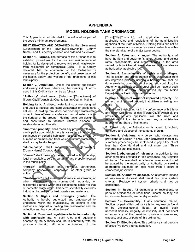
10 CMR 241 ( August 1, 2005) Page A-1
APPENDIX A
MODEL HOLDING TANK ORDINANCE
This Appendix is not intended to be enforced as part of the code’s minimum requirements.
BE IT ENACTED AND ORDAINED by the [Selectmen] [Councilmen] of the [Town][City][Township], [County Name], and it is hereby enacted and ordained as follows:
Section 1. Purpose. The purpose of this Ordinance is to establish procedures for the use and maintenance of holding tanks designed to receive and retain wastewater from residential or commercial uses. It is hereby declared that the enactment of this Ordinance is necessary for the protection, benefit, and preservation of the health, safety, and welfare of the inhabitants of this municipality.
Section 2. Definitions. Unless the context specifically and clearly indicates otherwise, the meaning of terms used in this Ordinance shall be as follows:
“Authority” shall mean [Selectmen][Councilmen] of [Town][City][Township], [County Name] County, Maine.
Holding tank: A closed, watertight structure designed and used to receive and store wastewater or septic tank effluent. A holding tank does not discharge wastewater or septic tank effluent to surface or ground water or onto the surface of the ground. Holding tanks are designed and constructed to facilitate ultimate disposal of wastewater at another site.
“Improved property” shall mean any property within the municipality upon which there is a structure intended for continuous or periodic habitation, occupancy, or use by humans or animals and from which structure wastewater shall or may be discharged.
“Municipality” shall mean [Town][City][Township], [County Name] County, Maine.
“Owner” shall mean any person vested with ownership, legal or equitable, sole or partial, of any property located in the municipality.
“Person” shall mean any individual, partnership, company, association, corporation, or other group or entity.
“Wastewater” shall mean any domestic wastewater, or other wastewater from commercial, industrial, or residential sources which has constituents similar to that of domestic wastewater. This term specifically excludes industrial, hazardous, or toxic wastes and materials.
Section 3. Rights and privileges granted. The Authority is hereby authorized and empowered to undertake, within the municipality, the control of and methods of disposal of holding tank wastewater and the collection and transportation thereof.
Section 4. Rules and regulations to be in conformity with applicable law. All such rules and regulations adopted by the Authority shall be in conformity with the provisions herein, all other ordinances of the
[Town][City][Township], all applicable laws, and applicable rules and regulations of the administrative agencies of the State of Maine. Holding tanks can not be used for seasonal conversion or new construction within the shoreland zone of a major water course.
Section 5. Rates and changes. The Authority shall have the right and power to fix, alter, charge, and collect rates, assessments, and other charges in the area served by its facilities at reasonable and uniform rates as authorized by applicable law.
Section 6. Exclusiveness of rights and privileges. The collection and transportation of all wastewater from any improved property utilizing a holding tank shall be done solely by, or under the direction and control of, the Authority, and the disposal thereof shall be made at such site or sites as may be approved by the Maine Department of Environmental Protection.
Section 7. Duties of owner of improved property. The owner of an improved property that utilizes a holding tank shall:
A. Maintain the holding tank in conformance with this or any other Ordinance of this [Town][City][Township], the provisions of any applicable law, the rules and regulations of the Authority, and any administrative agency of the State of Maine; and
B. Permit only the Authority, or its agent, to collect, transport, and dispose of the contents therein.
Section 8. Violations. Any person who violates any provisions of Section 7 shall, upon conviction thereof by summary proceedings, be sentenced to pay a fine of not less than One Hundred and not more than Three Hundred dollars, plus costs.
Section 9. Abatement of nuisances. In addition to any other remedies provided in this ordinance, any violation of Section 7 above shall constitute a nuisance and shall be abated by the municipality or Authority by seeking appropriate equitable or legal relief from a court of competent jurisdiction.
Section 10. Alternative disposal. An alternative means of wastewater disposal shall meet first time system criteria. Replacement system criteria shall not be considered.
Section 11. Repeal. All ordinances or resolutions, or parts of ordinances or resolutions, insofar as they are inconsistent herewith, are hereby repealed.
Section 12. Severability. If any sentence, clause, Section, or part of this ordinance is for any reason found to be unconstitutional, illegal, or invalid, such unconstitutionality, illegality, or invalidity shall not affect or impair any of the remaining provisions, sentences, clauses, sections, or parts of this ordinance.
Section 13. Effective date. This ordinance shall become effective five days after its adoption.
MODEL HOLDING TANK ORDINANCE
Page A-2 10 CMR 241 ( August 1, 2005)
ENACTED AND ORDAINED into an Ordinance this [Day]day of [Month]A.D., [Year] of the [Selectmen] [Councilmen] of the [Town][City][Township] of [County] County in lawful session duly assembled.
[Selectmen][Councilmen] of the [Town][City][Township] of
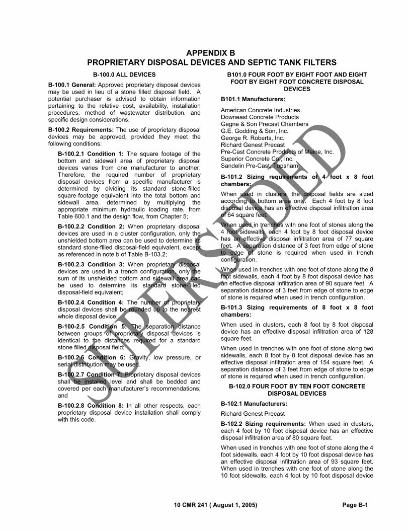
10 CMR 241 ( August 1, 2005) Page B-1
APPENDIX B PROPRIETARY DISPOSAL DEVICES AND SEPTIC TANK FILTERS
B-100.0 ALL DEVICES
B-100.1 General: Approved proprietary disposal devices may be used in lieu of a stone filled disposal field. A potential purchaser is advised to obtain information pertaining to the relative cost, availability, installation procedures, method of wastewater distribution, and specific design considerations.
B-100.2 Requirements: The use of proprietary disposal devices may be approved, provided they meet the following conditions:
B-100.2.1 Condition 1: The square footage of the bottom and sidewall area of proprietary disposal devices varies from one manufacturer to another. Therefore, the required number of proprietary disposal devices from a specific manufacturer is determined by dividing its standard stone-filled square-footage equivalent into the total bottom and sidewall area, determined by multiplying the appropriate minimum hydraulic loading rate, from Table 600.1 and the design flow, from Chapter 5;
B-100.2.2 Condition 2: When proprietary disposal devices are used in a cluster configuration, only the unshielded bottom area can be used to determine its standard stone-filled disposal-field equivalent, except as referenced in note b of Table B-103.2;
B-100.2.3 Condition 3: When proprietary disposal devices are used in a trench configuration, only the sum of its unshielded bottom and sidewall area can be used to determine its standard stone-filled disposal-field equivalent;
B-100.2.4 Condition 4: The number of proprietary disposal devices shall be rounded up to the nearest whole disposal device;
B-100-2.5 Condition 5: The separation distance between groups of proprietary disposal devices is identical to the distances required for a standard stone filled disposal field;
B-100.2.6 Condition 6: Gravity, low pressure, or serial distribution may be used.
B-100.2.7 Condition 7: Proprietary disposal devices shall be installed level and shall be bedded and covered per each manufacturer’s recommendations; and
B-100.2.8 Condition 8: In all other respects, each proprietary disposal device installation shall comply with this code.
B101.0 FOUR FOOT BY EIGHT FOOT AND EIGHT FOOT BY EIGHT FOOT CONCRETE DISPOSAL
DEVICES
B101.1 Manufacturers:
American Concrete Industries Downeast Concrete Products Gagne & Son Precast Chambers G.E. Godding & Son, Inc. George R. Roberts, Inc. Richard Genest Precast Pre-Cast Concrete Products of Maine, Inc. Superior Concrete Co., Inc. Sandelin Pre-Cast, Topsham
B-101.2 Sizing requirements of 4 foot x 8 foot chambers:
When used in clusters, the disposal fields are sized according to bottom area only. Each 4 foot by 8 foot disposal device has an effective disposal infiltration area of 64 square feet.
When used in trenches with one foot of stones along the 4 foot sidewalls, each 4 foot by 8 foot disposal device has an effective disposal infiltration area of 77 square feet. A separation distance of 3 feet from edge of stone to edge of stone is required when used in trench configuration.
When used in trenches with one foot of stone along the 8 foot sidewalls, each 4 foot by 8 foot disposal device has an effective disposal infiltration area of 90 square feet. A separation distance of 3 feet from edge of stone to edge of stone is required when used in trench configuration.
B-101.3 Sizing requirements of 8 foot x 8 foot chambers:
When used in clusters, each 8 foot by 8 foot disposal device has an effective disposal infiltration area of 128 square feet.
When used in trenches with one foot of stone along two sidewalls, each 8 foot by 8 foot disposal device has an effective disposal infiltration area of 154 square feet. A separation distance of 3 feet from edge of stone to edge of stone is required when used in trench configuration.
B-102.0 FOUR FOOT BY TEN FOOT CONCRETE DISPOSAL DEVICES
B-102.1 Manufacturers:
Richard Genest Precast
B-102.2 Sizing requirements: When used in clusters, each 4 foot by 10 foot disposal device has an effective disposal infiltration area of 80 square feet.
When used in trenches with one foot of stone along the 4 foot sidewalls, each 4 foot by 10 foot disposal device has an effective disposal infiltration area of 93 square feet. When used in trenches with one foot of stone along the 10 foot sidewalls, each 4 foot by 10 foot disposal device
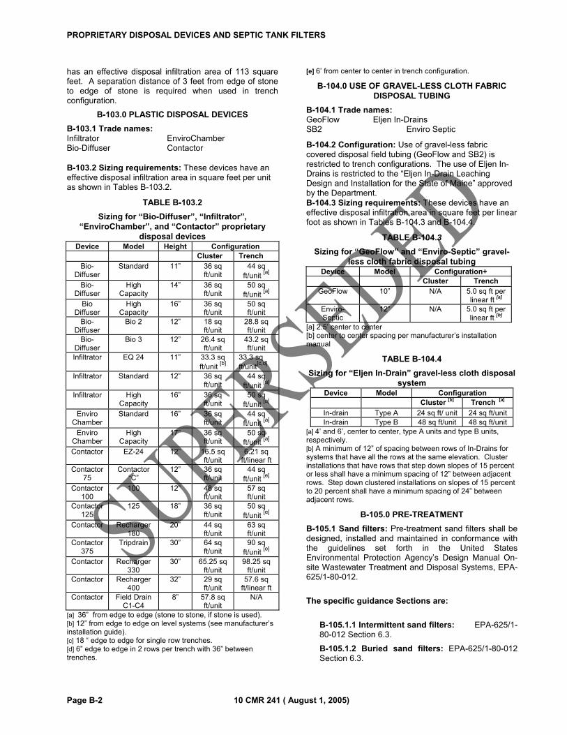
PROPRIETARY DISPOSAL DEVICES AND SEPTIC TANK FILTERS
Page B-2 10 CMR 241 ( August 1, 2005)
has an effective disposal infiltration area of 113 square feet. A separation distance of 3 feet from edge of stone to edge of stone is required when used in trench configuration.
B-103.0 PLASTIC DISPOSAL DEVICES
B-103.1 Trade names: Infiltrator EnviroChamber Bio-Diffuser Contactor B-103.2 Sizing requirements: These devices have an effective disposal infiltration area in square feet per unit as shown in Tables B-103.2.
TABLE B-103.2
Sizing for “Bio-Diffuser”, “Infiltrator”, “EnviroChamber”, and “Contactor” proprietary
disposal devices Device Model Height Configuration
Cluster Trench Bio-
Diffuser Standard 11” 36 sq
ft/unit 44 sq
ft/unit [a]
Bio-Diffuser
High Capacity
14” 36 sq ft/unit
50 sq ft/unit
[a] Bio
Diffuser High
Capacity 16” 36 sq
ft/unit 50 sq ft/unit
Bio-Diffuser
Bio 2 12” 18 sq ft/unit
28.8 sq ft/unit
Bio-Diffuser
Bio 3 12” 26.4 sq ft/unit
43.2 sq ft/unit
Infiltrator EQ 24 11” 33.3 sq ft/unit
[b] 33.3 sq ft/unit
[c,d] Infiltrator Standard 12” 36 sq
ft/unit 44 sq
ft/unit [a]
Infiltrator High Capacity
16” 36 sq ft/unit
50 sq ft/unit
[a] Enviro
Chamber Standard 16” 36 sq
ft/unit 44 sq
ft/unit [a]
Enviro Chamber
High Capacity
17” 36 sq ft/unit
50 sq ft/unit
[a] Contactor EZ-24 12” 16.5 sq
ft/unit 6.21 sq
ft/linear ft Contactor
75 Contactor
“C” 12” 36 sq
ft/unit 44 sq
ft/unit [e]
Contactor 100
100 12” 48 sq ft/unit
57 sq ft/unit
Contactor 125
125 18” 36 sq ft/unit
50 sq ft/unit
[e] Contactor Recharger
180 20” 44 sq
ft/unit 63 sq ft/unit
Contactor 375
Tripdrain 30” 64 sq ft/unit
90 sq ft/unit
[e] Contactor Recharger
330 30” 65.25 sq
ft/unit 98.25 sq
ft/unit Contactor Recharger
400 32” 29 sq
ft/unit 57.6 sq
ft/linear ft Contactor Field Drain
C1-C4 8” 57.8 sq
ft/unit N/A
[a] 36” from edge to edge (stone to stone, if stone is used).
[b] 12” from edge to edge on level systems (see manufacturer’s installation guide). [c] 18 “ edge to edge for single row trenches. [d] 6” edge to edge in 2 rows per trench with 36” between trenches.
[e] 6’ from center to center in trench configuration.
B-104.0 USE OF GRAVEL-LESS CLOTH FABRIC DISPOSAL TUBING
B-104.1 Trade names: GeoFlow Eljen In-Drains SB2 Enviro Septic
B-104.2 Configuration: Use of gravel-less fabric covered disposal field tubing (GeoFlow and SB2) is restricted to trench configurations. The use of Eljen In-Drains is restricted to the “Eljen In-Drain Leaching Design and Installation for the State of Maine” approved by the Department. B-104.3 Sizing requirements: These devices have an effective disposal infiltration area in square feet per linear foot as shown in Tables B-104.3 and B-104.4.
TABLE B-104.3
Sizing for “GeoFlow” and “Enviro-Septic” gravel-less cloth fabric disposal tubing
Device Model Configuration+ Cluster Trench
GeoFlow 10” N/A 5.0 sq ft per linear ft [a]
Enviro-Septic
12” N/A 5.0 sq ft per linear ft [b]
[a] 2.5’ center to center [b] center to center spacing per manufacturer’s installation manual
TABLE B-104.4
Sizing for “Eljen In-Drain” gravel-less cloth disposal system
Device Model Configuration
Cluster [b] Trench [a]
In-drain Type A 24 sq ft/ unit 24 sq ft/unitIn-drain Type B 48 sq ft/unit 48 sq ft/unit
[a] 4’ and 6’, center to center, type A units and type B units,
respectively. [b] A minimum of 12” of spacing between rows of In-Drains for systems that have all the rows at the same elevation. Cluster installations that have rows that step down slopes of 15 percent or less shall have a minimum spacing of 12” between adjacent rows. Step down clustered installations on slopes of 15 percent to 20 percent shall have a minimum spacing of 24” between adjacent rows.
B-105.0 PRE-TREATMENT
B-105.1 Sand filters: Pre-treatment sand filters shall be designed, installed and maintained in conformance with the guidelines set forth in the United States Environmental Protection Agency’s Design Manual On-site Wastewater Treatment and Disposal Systems, EPA-625/1-80-012.
The specific guidance Sections are:
B-105.1.1 Intermittent sand filters: EPA-625/1-80-012 Section 6.3.
B-105.1.2 Buried sand filters: EPA-625/1-80-012 Section 6.3.
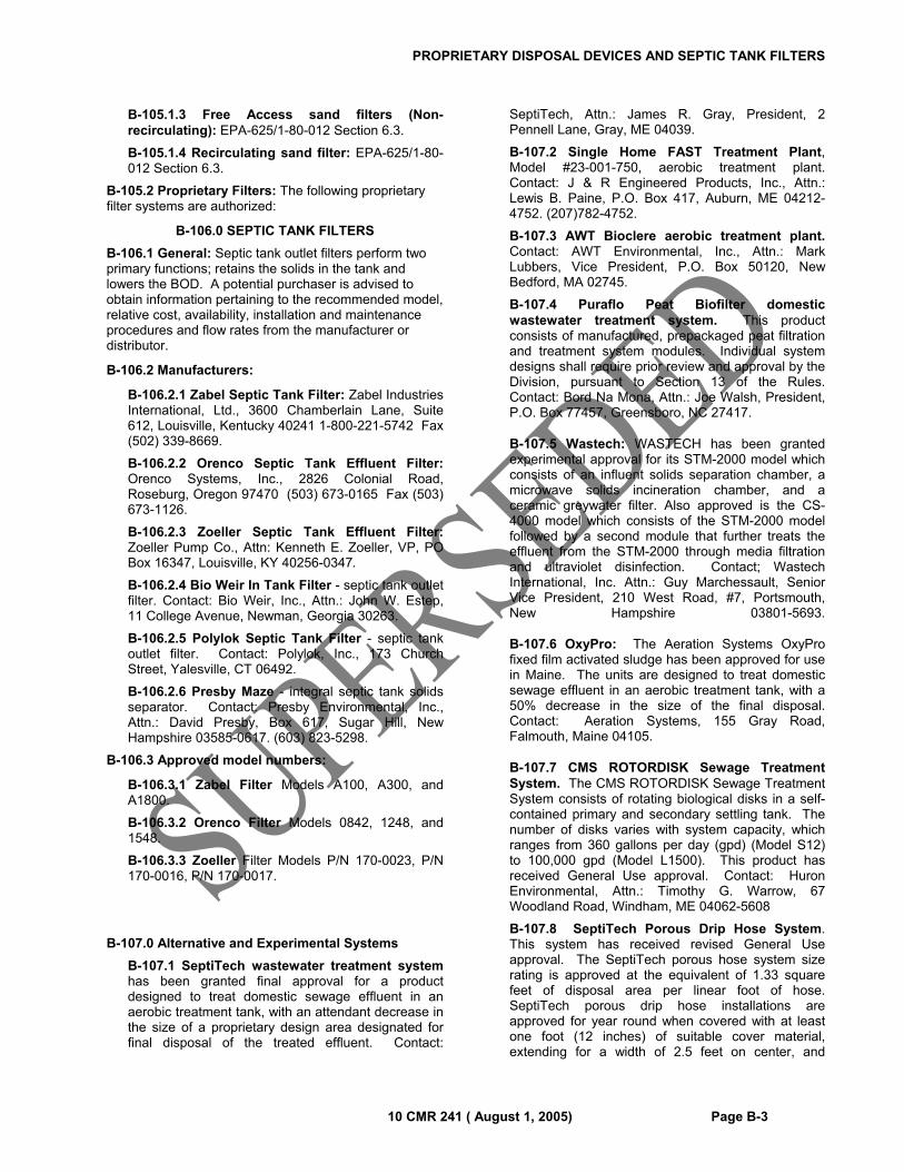
PROPRIETARY DISPOSAL DEVICES AND SEPTIC TANK FILTERS
10 CMR 241 ( August 1, 2005) Page B-3
B-105.1.3 Free Access sand filters (Non-recirculating): EPA-625/1-80-012 Section 6.3.
B-105.1.4 Recirculating sand filter: EPA-625/1-80-012 Section 6.3.
B-105.2 Proprietary Filters: The following proprietary filter systems are authorized:
B-106.0 SEPTIC TANK FILTERS
B-106.1 General: Septic tank outlet filters perform two primary functions; retains the solids in the tank and lowers the BOD. A potential purchaser is advised to obtain information pertaining to the recommended model, relative cost, availability, installation and maintenance procedures and flow rates from the manufacturer or distributor.
B-106.2 Manufacturers:
B-106.2.1 Zabel Septic Tank Filter: Zabel Industries International, Ltd., 3600 Chamberlain Lane, Suite 612, Louisville, Kentucky 40241 1-800-221-5742 Fax (502) 339-8669.
B-106.2.2 Orenco Septic Tank Effluent Filter: Orenco Systems, Inc., 2826 Colonial Road, Roseburg, Oregon 97470 (503) 673-0165 Fax (503) 673-1126.
B-106.2.3 Zoeller Septic Tank Effluent Filter: Zoeller Pump Co., Attn: Kenneth E. Zoeller, VP, PO Box 16347, Louisville, KY 40256-0347.
B-106.2.4 Bio Weir In Tank Filter - septic tank outlet filter. Contact: Bio Weir, Inc., Attn.: John W. Estep, 11 College Avenue, Newman, Georgia 30263.
B-106.2.5 Polylok Septic Tank Filter - septic tank outlet filter. Contact: Polylok, Inc., 173 Church Street, Yalesville, CT 06492.
B-106.2.6 Presby Maze - integral septic tank solids separator. Contact: Presby Environmental, Inc., Attn.: David Presby, Box 617, Sugar Hill, New Hampshire 03585-0617. (603) 823-5298.
B-106.3 Approved model numbers:
B-106.3.1 Zabel Filter Models A100, A300, and A1800.
B-106.3.2 Orenco Filter Models 0842, 1248, and 1548.
B-106.3.3 Zoeller Filter Models P/N 170-0023, P/N 170-0016, P/N 170-0017.
B-107.0 Alternative and Experimental Systems
B-107.1 SeptiTech wastewater treatment system has been granted final approval for a product designed to treat domestic sewage effluent in an aerobic treatment tank, with an attendant decrease in the size of a proprietary design area designated for final disposal of the treated effluent. Contact:
SeptiTech, Attn.: James R. Gray, President, 2 Pennell Lane, Gray, ME 04039.
B-107.2 Single Home FAST Treatment Plant, Model #23-001-750, aerobic treatment plant. Contact: J & R Engineered Products, Inc., Attn.: Lewis B. Paine, P.O. Box 417, Auburn, ME 04212-4752. (207)782-4752.
B-107.3 AWT Bioclere aerobic treatment plant. Contact: AWT Environmental, Inc., Attn.: Mark Lubbers, Vice President, P.O. Box 50120, New Bedford, MA 02745.
B-107.4 Puraflo Peat Biofilter domestic wastewater treatment system. This product consists of manufactured, prepackaged peat filtration and treatment system modules. Individual system designs shall require prior review and approval by the Division, pursuant to Section 13 of the Rules. Contact: Bord Na Mona, Attn.: Joe Walsh, President, P.O. Box 77457, Greensboro, NC 27417.
B-107.5 Wastech: WASTECH has been granted experimental approval for its STM-2000 model which consists of an influent solids separation chamber, a microwave solids incineration chamber, and a ceramic greywater filter. Also approved is the CS-4000 model which consists of the STM-2000 model followed by a second module that further treats the effluent from the STM-2000 through media filtration and ultraviolet disinfection. Contact; Wastech International, Inc. Attn.: Guy Marchessault, Senior Vice President, 210 West Road, #7, Portsmouth, New Hampshire 03801-5693. B-107.6 OxyPro: The Aeration Systems OxyPro fixed film activated sludge has been approved for use in Maine. The units are designed to treat domestic sewage effluent in an aerobic treatment tank, with a 50% decrease in the size of the final disposal. Contact: Aeration Systems, 155 Gray Road, Falmouth, Maine 04105.
B-107.7 CMS ROTORDISK Sewage Treatment System. The CMS ROTORDISK Sewage Treatment System consists of rotating biological disks in a self-contained primary and secondary settling tank. The number of disks varies with system capacity, which ranges from 360 gallons per day (gpd) (Model S12) to 100,000 gpd (Model L1500). This product has received General Use approval. Contact: Huron Environmental, Attn.: Timothy G. Warrow, 67 Woodland Road, Windham, ME 04062-5608
B-107.8 SeptiTech Porous Drip Hose System. This system has received revised General Use approval. The SeptiTech porous hose system size rating is approved at the equivalent of 1.33 square feet of disposal area per linear foot of hose. SeptiTech porous drip hose installations are approved for year round when covered with at least one foot (12 inches) of suitable cover material, extending for a width of 2.5 feet on center, and
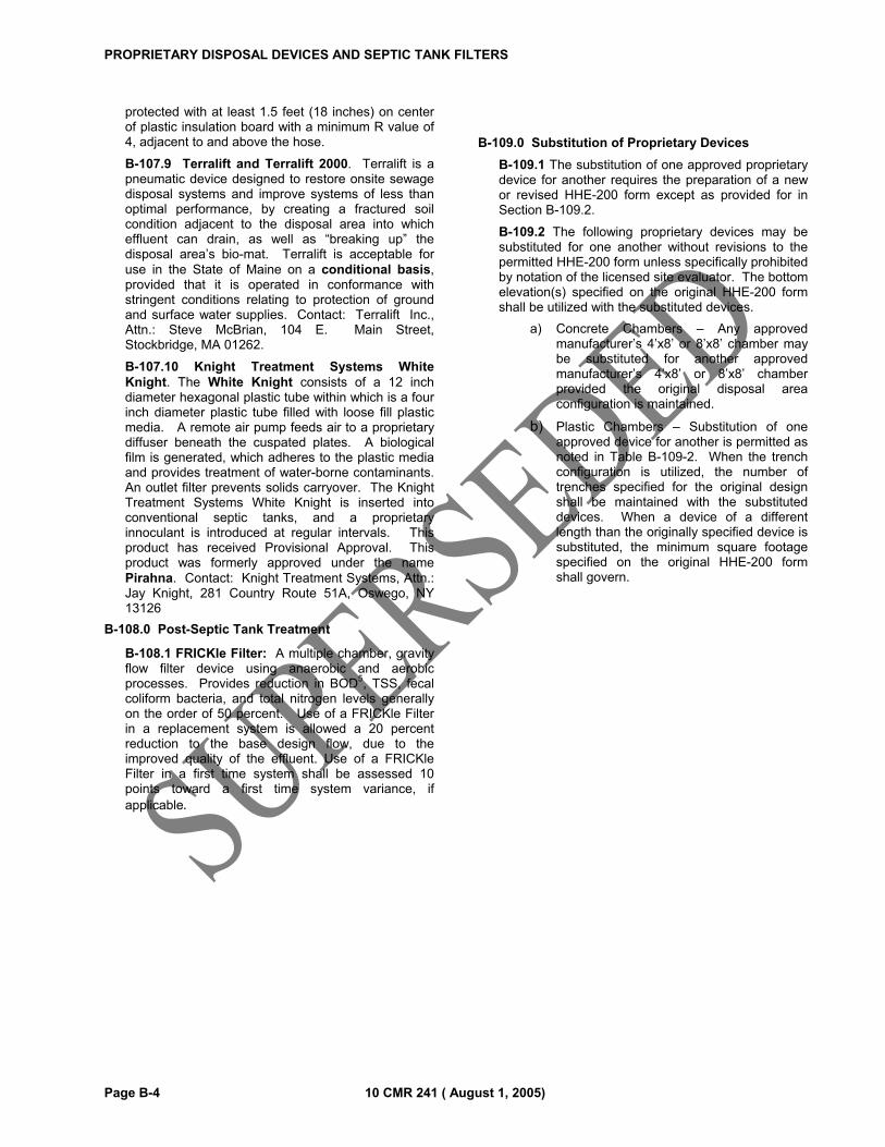
PROPRIETARY DISPOSAL DEVICES AND SEPTIC TANK FILTERS
Page B-4 10 CMR 241 ( August 1, 2005)
protected with at least 1.5 feet (18 inches) on center of plastic insulation board with a minimum R value of 4, adjacent to and above the hose.
B-107.9 Terralift and Terralift 2000. Terralift is a pneumatic device designed to restore onsite sewage disposal systems and improve systems of less than optimal performance, by creating a fractured soil condition adjacent to the disposal area into which effluent can drain, as well as “breaking up” the disposal area’s bio-mat. Terralift is acceptable for use in the State of Maine on a conditional basis, provided that it is operated in conformance with stringent conditions relating to protection of ground and surface water supplies. Contact: Terralift Inc., Attn.: Steve McBrian, 104 E. Main Street, Stockbridge, MA 01262.
B-107.10 Knight Treatment Systems White Knight. The White Knight consists of a 12 inch diameter hexagonal plastic tube within which is a four inch diameter plastic tube filled with loose fill plastic media. A remote air pump feeds air to a proprietary diffuser beneath the cuspated plates. A biological film is generated, which adheres to the plastic media and provides treatment of water-borne contaminants. An outlet filter prevents solids carryover. The Knight Treatment Systems White Knight is inserted into conventional septic tanks, and a proprietary innoculant is introduced at regular intervals. This product has received Provisional Approval. This product was formerly approved under the name Pirahna. Contact: Knight Treatment Systems, Attn.: Jay Knight, 281 Country Route 51A, Oswego, NY 13126
B-108.0 Post-Septic Tank Treatment
B-108.1 FRICKle Filter: A multiple chamber, gravity flow filter device using anaerobic and aerobic processes. Provides reduction in BOD5, TSS, fecal coliform bacteria, and total nitrogen levels generally on the order of 50 percent. Use of a FRICKle Filter in a replacement system is allowed a 20 percent reduction to the base design flow, due to the improved quality of the effluent. Use of a FRICKle Filter in a first time system shall be assessed 10 points toward a first time system variance, if applicable.
B-109.0 Substitution of Proprietary Devices
B-109.1 The substitution of one approved proprietary device for another requires the preparation of a new or revised HHE-200 form except as provided for in Section B-109.2.
B-109.2 The following proprietary devices may be substituted for one another without revisions to the permitted HHE-200 form unless specifically prohibited by notation of the licensed site evaluator. The bottom elevation(s) specified on the original HHE-200 form shall be utilized with the substituted devices.
a) Concrete Chambers – Any approved manufacturer’s 4’x8’ or 8’x8’ chamber may be substituted for another approved manufacturer’s 4’x8’ or 8’x8’ chamber provided the original disposal area configuration is maintained.
b) Plastic Chambers – Substitution of one approved device for another is permitted as noted in Table B-109-2. When the trench configuration is utilized, the number of trenches specified for the original design shall be maintained with the substituted devices. When a device of a different length than the originally specified device is substituted, the minimum square footage specified on the original HHE-200 form shall govern.
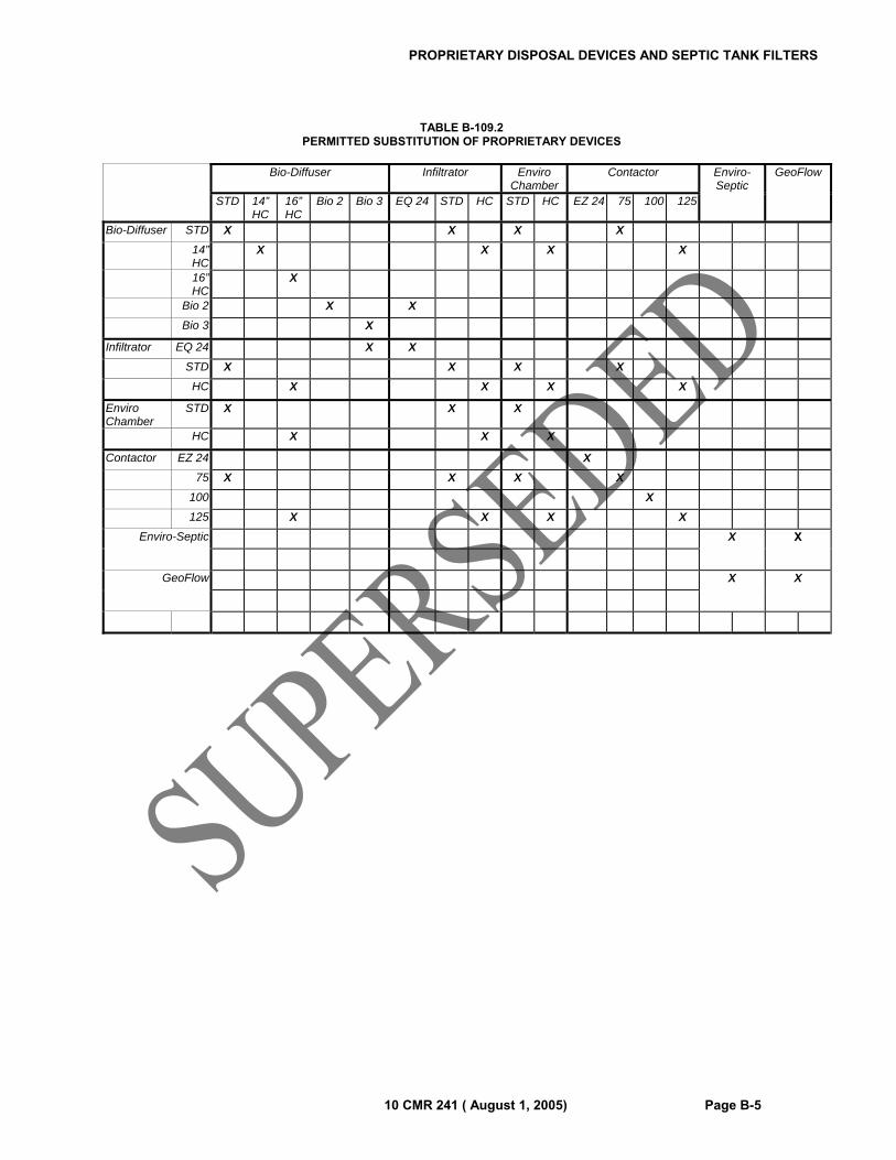
PROPRIETARY DISPOSAL DEVICES AND SEPTIC TANK FILTERS
10 CMR 241 ( August 1, 2005) Page B-5
TABLE B-109.2 PERMITTED SUBSTITUTION OF PROPRIETARY DEVICES
Bio-Diffuser Infiltrator Enviro
Chamber Contactor Enviro-
Septic GeoFlow
STD 14” HC
16” HC
Bio 2 Bio 3 EQ 24 STD HC STD HC EZ 24 75 100 125
Bio-Diffuser STD X X X X
14” HC
X X X X
16” HC
X
Bio 2 X X
Bio 3 X
Infiltrator EQ 24 X X
STD X X X X
HC X X X X
Enviro Chamber
STD X X X
HC X X X
Contactor EZ 24 X
75 X X X X
100 X
125 X X X X
Enviro-Septic
X X
GeoFlow
X X

PROPRIETARY DISPOSAL DEVICES AND SEPTIC TANK FILTERS
Page B-6 10 CMR 241 (October 1, 2002)
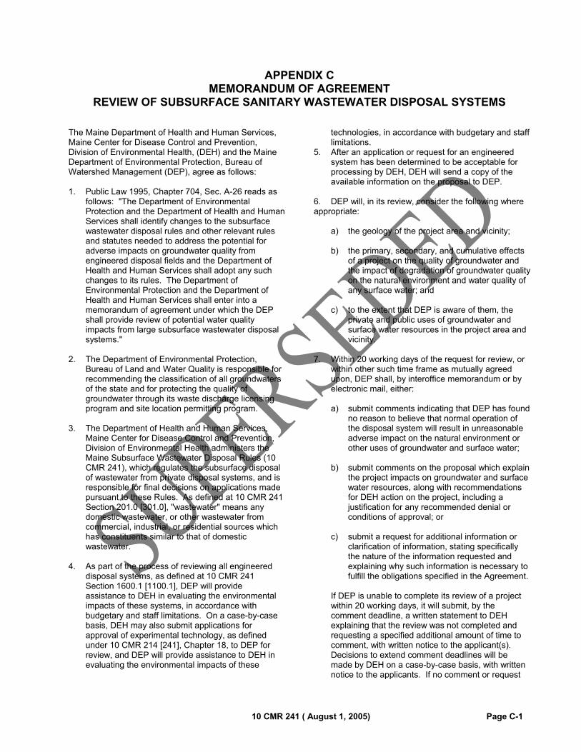
10 CMR 241 ( August 1, 2005) Page C-1
APPENDIX C MEMORANDUM OF AGREEMENT
REVIEW OF SUBSURFACE SANITARY WASTEWATER DISPOSAL SYSTEMS
The Maine Department of Health and Human Services, Maine Center for Disease Control and Prevention, Division of Environmental Health, (DEH) and the Maine Department of Environmental Protection, Bureau of Watershed Management (DEP), agree as follows: 1. Public Law 1995, Chapter 704, Sec. A-26 reads as
follows: "The Department of Environmental Protection and the Department of Health and Human Services shall identify changes to the subsurface wastewater disposal rules and other relevant rules and statutes needed to address the potential for adverse impacts on groundwater quality from engineered disposal fields and the Department of Health and Human Services shall adopt any such changes to its rules. The Department of Environmental Protection and the Department of Health and Human Services shall enter into a memorandum of agreement under which the DEP shall provide review of potential water quality impacts from large subsurface wastewater disposal systems."
2. The Department of Environmental Protection,
Bureau of Land and Water Quality is responsible for recommending the classification of all groundwaters of the state and for protecting the quality of groundwater through its waste discharge licensing program and site location permitting program.
3. The Department of Health and Human Services,
Maine Center for Disease Control and Prevention, Division of Environmental Health administers the Maine Subsurface Wastewater Disposal Rules (10 CMR 241), which regulates the subsurface disposal of wastewater from private disposal systems, and is responsible for final decisions on applications made pursuant to these Rules. As defined at 10 CMR 241 Section 201.0 [301.0], "wastewater" means any domestic wastewater, or other wastewater from commercial, industrial, or residential sources which has constituents similar to that of domestic wastewater.
4. As part of the process of reviewing all engineered
disposal systems, as defined at 10 CMR 241 Section 1600.1 [1100.1], DEP will provide assistance to DEH in evaluating the environmental impacts of these systems, in accordance with budgetary and staff limitations. On a case-by-case basis, DEH may also submit applications for approval of experimental technology, as defined under 10 CMR 214 [241], Chapter 18, to DEP for review, and DEP will provide assistance to DEH in evaluating the environmental impacts of these
technologies, in accordance with budgetary and staff limitations.
5. After an application or request for an engineered system has been determined to be acceptable for processing by DEH, DEH will send a copy of the available information on the proposal to DEP.
6. DEP will, in its review, consider the following where appropriate:
a) the geology of the project area and vicinity;
b) the primary, secondary, and cumulative effects of a project on the quality of groundwater and the impact of degradation of groundwater quality on the natural environment and water quality of any surface water; and
c) to the extent that DEP is aware of them, the private and public uses of groundwater and surface water resources in the project area and vicinity.
7. Within 20 working days of the request for review, or
within other such time frame as mutually agreed upon, DEP shall, by interoffice memorandum or by electronic mail, either:
a) submit comments indicating that DEP has found
no reason to believe that normal operation of the disposal system will result in unreasonable adverse impact on the natural environment or other uses of groundwater and surface water;
b) submit comments on the proposal which explain the project impacts on groundwater and surface water resources, along with recommendations for DEH action on the project, including a justification for any recommended denial or conditions of approval; or
c) submit a request for additional information or clarification of information, stating specifically the nature of the information requested and explaining why such information is necessary to fulfill the obligations specified in the Agreement.
If DEP is unable to complete its review of a project
within 20 working days, it will submit, by the comment deadline, a written statement to DEH explaining that the review was not completed and requesting a specified additional amount of time to comment, with written notice to the applicant(s). Decisions to extend comment deadlines will be made by DEH on a case-by-case basis, with written notice to the applicants. If no comment or request
MEMORANDUM OF AGREEMENT
Page C-2 10 CMR 241 ( August 1, 2005)
for a specified additional amount of time is received from DEP within 20 working days, then DEH will assume that DEP has no concerns about the system and will act accordingly.
8. In those cases for which the conditions of DEH
approval of an engineered system require the submission of additional plans or data for review, DEH will send copies of the plans or data to DEP for review and comment in accordance with the terms outlined above, unless the opportunity for such review and comment is specifically waived by DEP.
9. DEH will consider DEP's recommendations for
action on the proposed disposal system, and will incorporate them in DEH's final action as appropriate. Any disagreements will be discussed and resolved if possible at the staff level. Any disagreements not resolved at the staff level will be taken to the Director of the Division of Environmental Health and the Director of the DEP Bureau of Land and Water Quality for resolution.
10. DEH will provide DEP with a copy of all permitting
actions taken on engineered disposal systems and experimental technology, as described above.
11. DEP will provide DEH with a copy of all permitting
actions on projects involving subsurface disposal systems that are reviewed under the Site Location of Development Act.
12. DEH will, on a continuing basis, provide DEP with
copies of current revised versions of the Maine Subsurface Wastewater Disposal Rules and any statutes, advisory opinions, technical notes, and other information relating to engineered systems, in such quantities as requested by DEP. DEH will also solicit comment from DEP on any proposed policies or rules relating to the use of engineered systems for subsurface wastewater disposal.
13. DEP will, on a continuing basis, provide DEH with
copies of current revised versions of the Site Location of Development Regulations and any statutes, advisory opinions and policies relating to subsurface wastewater disposal, in such quantities as requested by DEH. DEP will also solicit comment from DEH on any proposed policies or rules relating to engineered systems for subsurface wastewater disposal.
14. Copies of this Agreement will be provided to all DEH
and DEP staff reviewing engineered systems under the terms of this Agreement.
15. Notification of this MOA will be made by DEH to all
Site Evaluators and all practicing Licensed Professional Engineers of record who have provided subsurface designs to the Division of Environmental Health.
16. This Memorandum of Agreement applies to all engineered systems, including those which may be part of a development regulated under the Site Location of Development Act (38 M.R.S.A., Section 481 et seq.). Review of engineered systems in developments regulated under the Site Location of Development Act will be subject to the conditions of this MOA.
17. DEP and DEH will consult at least annually to
identify changes to the subsurface wastewater disposal rules and other relevant rules and statutes needed to address the potential for adverse impacts on groundwater quality from engineered systems.
18. The terms of this Agreement shall be subject to
review and revision at any time upon request by either DEH or DEP.

10 CMR 241 ( August 1, 2005) Page D-1
APPENDIX D
FORMS
SECTION D-100.0 LIST OF FORMS AND NUMBERS
HHE-200 Subsurface Wastewater Disposal System Application (3 pages)
HHE-204 Replacement System Variance Request (Section 1906.0)
HHE-215 First Time System Variance Request (Section 1901.2.1; 1904.1)
HHE-233 Application/Agreement for Holding Tank Installation (Section 2001.2.2)
HHE-234 Notice of Intent to Install a Subsurface Wastewater Disposal System (Section 1703.3.2)
HHE-236 Application for Variance to the Minimum Lot Size Law Requirements
HHE-238A Statement of Compliance (Section 111.10, 120.3.2, and 1202.4)
HHE-238B Affidavit of Site Preparation (Section 111.5.1)
HHE-300 Holding Tank Deed Covenant (Section 2002.1.5)
HHE-304 Subsurface Wastewater Disposal Variance Deed Covenant (Section 1904.7)
HHE-306 Well Setback Release Form (Section 702.5 and 702.6)
SECTION D-101.0 FORM SAMPLES
D-101.1 Samples of the forms listed in Section D-100.0 are found on the following pages.

FORMS
Page D-2 10 CMR 241 ( August 1, 2005)

FORMS
10 CMR 241 ( August 1, 2005) Page D-3

FORMS
Page D-4 10 CMR 241 ( August 1, 2005)
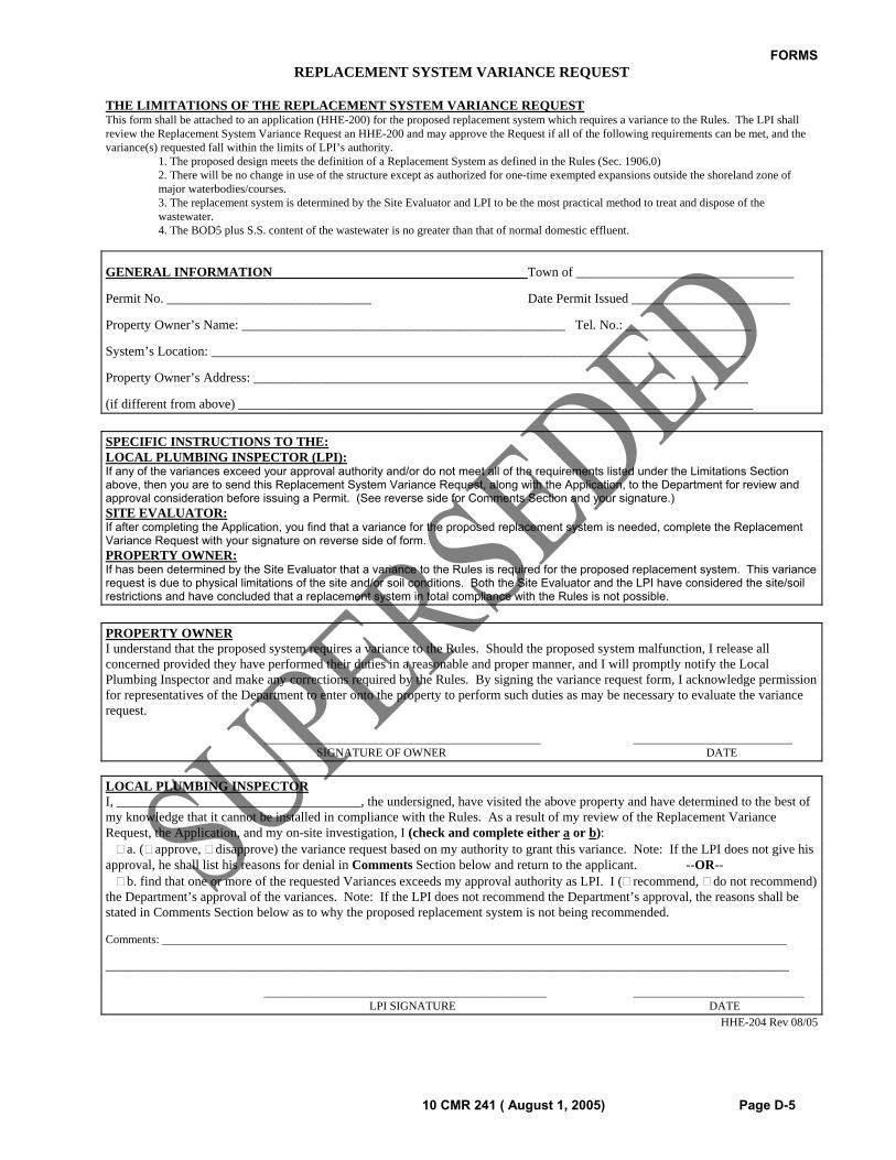
FORMS
10 CMR 241 ( August 1, 2005) Page D-5
REPLACEMENT SYSTEM VARIANCE REQUEST THE LIMITATIONS OF THE REPLACEMENT SYSTEM VARIANCE REQUEST This form shall be attached to an application (HHE-200) for the proposed replacement system which requires a variance to the Rules. The LPI shall review the Replacement System Variance Request an HHE-200 and may approve the Request if all of the following requirements can be met, and the variance(s) requested fall within the limits of LPI’s authority. 1. The proposed design meets the definition of a Replacement System as defined in the Rules (Sec. 1906.0) 2. There will be no change in use of the structure except as authorized for one-time exempted expansions outside the shoreland zone of
major waterbodies/courses. 3. The replacement system is determined by the Site Evaluator and LPI to be the most practical method to treat and dispose of the
wastewater. 4. The BOD5 plus S.S. content of the wastewater is no greater than that of normal domestic effluent.
GENERAL INFORMATION Town of _________________________________
Permit No. _______________________________ Date Permit Issued ________________________
Property Owner’s Name: _________________________________________________ Tel. No.: ___________________
System’s Location: _________________________________________________________________________________
Property Owner’s Address: ___________________________________________________________________________
(if different from above) ______________________________________________________________________________
SPECIFIC INSTRUCTIONS TO THE: LOCAL PLUMBING INSPECTOR (LPI): If any of the variances exceed your approval authority and/or do not meet all of the requirements listed under the Limitations Section above, then you are to send this Replacement System Variance Request, along with the Application, to the Department for review and approval consideration before issuing a Permit. (See reverse side for Comments Section and your signature.) SITE EVALUATOR: If after completing the Application, you find that a variance for the proposed replacement system is needed, complete the Replacement Variance Request with your signature on reverse side of form. PROPERTY OWNER: If has been determined by the Site Evaluator that a variance to the Rules is required for the proposed replacement system. This variance request is due to physical limitations of the site and/or soil conditions. Both the Site Evaluator and the LPI have considered the site/soil restrictions and have concluded that a replacement system in total compliance with the Rules is not possible.
PROPERTY OWNER I understand that the proposed system requires a variance to the Rules. Should the proposed system malfunction, I release all concerned provided they have performed their duties in a reasonable and proper manner, and I will promptly notify the Local Plumbing Inspector and make any corrections required by the Rules. By signing the variance request form, I acknowledge permission for representatives of the Department to enter onto the property to perform such duties as may be necessary to evaluate the variance request. _______________________________________________ ___________________________ SIGNATURE OF OWNER DATE
LOCAL PLUMBING INSPECTOR I, _____________________________________, the undersigned, have visited the above property and have determined to the best of my knowledge that it cannot be installed in compliance with the Rules. As a result of my review of the Replacement Variance Request, the Application, and my on-site investigation, I (check and complete either a or b): a. ( approve, disapprove) the variance request based on my authority to grant this variance. Note: If the LPI does not give his approval, he shall list his reasons for denial in Comments Section below and return to the applicant. --OR-- b. find that one or more of the requested Variances exceeds my approval authority as LPI. I ( recommend, do not recommend) the Department’s approval of the variances. Note: If the LPI does not recommend the Department’s approval, the reasons shall be stated in Comments Section below as to why the proposed replacement system is not being recommended.
Comments: __________________________________________________________________________________________________________
____________________________________________________________________________________________________________________
________________________________________________ _____________________________ LPI SIGNATURE DATE
HHE-204 Rev 08/05
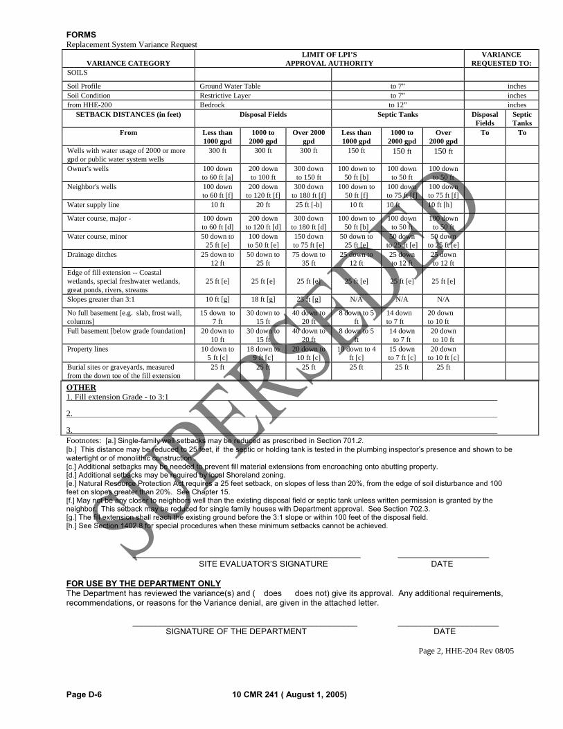
FORMS
Page D-6 10 CMR 241 ( August 1, 2005)
Replacement System Variance Request
VARIANCE CATEGORY LIMIT OF LPI’S
APPROVAL AUTHORITYVARIANCE
REQUESTED TO:SOILS Soil Profile Ground Water Table to 7” inchesSoil Condition Restrictive Layer to 7” inchesfrom HHE-200 Bedrock to 12” inches
SETBACK DISTANCES (in feet) Disposal Fields Septic Tanks Disposal Fields
Septic Tanks
From Less than 1000 gpd
1000 to 2000 gpd
Over 2000 gpd
Less than 1000 gpd
1000 to 2000 gpd
Over 2000 gpd
To To
Wells with water usage of 2000 or more gpd or public water system wells
300 ft 300 ft 300 ft 150 ft 150 ft 150 ft Owner's wells 100 down
to 60 ft [a] 200 down to 100 ft
300 down to 150 ft
100 down to 50 ft [b]
100 down to 50 ft
100 down to 50 ft
Neighbor's wells 100 down
to 60 ft [f]200 down
to 120 ft [f]300 down
to 180 ft [f]100 down to
50 ft [f]100 down to 75 ft [f]
100 down to 75 ft [f]
Water supply line 10 ft 20 ft 25 ft [-h] 10 ft 10 ft 10 ft [h] Water course, major - 100 down
to 60 ft [d]200 down
to 120 ft [d]300 down
to 180 ft [d]100 down to
50 ft [b]100 down
to 50 ft 100 down
to 50 ft
Water course, minor 50 down to 25 ft [e]
100 down to 50 ft [e]
150 down to 75 ft [e]
50 down to 25 ft [e]
50 down to 25 ft [e]
50 down to 25 ft [e]
Drainage ditches 25 down to
12 ft 50 down to
25 ft75 down to
35 ft25 down to
12 ft25 down to 12 ft
25 down to 12 ft
Edge of fill extension -- Coastal wetlands, special freshwater wetlands, great ponds, rivers, streams
25 ft [e]
25 ft [e]
25 ft [e]
25 ft [e]
25 ft [e]
25 ft [e]
Slopes greater than 3:1 10 ft [g] 18 ft [g] 25 ft [g] N/A N/A N/A No full basement [e.g. slab, frost wall, columns]
15 down to 7 ft
30 down to 15 ft
40 down to 20 ft
8 down to 5 ft
14 down to 7 ft
20 down to 10 ft
Full basement [below grade foundation] 20 down to
10 ft 30 down to
15 ft40 down to
20 ft8 down to 5
ft14 down
to 7 ft 20 down to 10 ft
Property lines 10 down to
5 ft [c]18 down to
9 ft [c]20 down to
10 ft [c]10 down to 4
ft [c]15 down to 7 ft [c]
20 down to 10 ft [c]
Burial sites or graveyards, measured from the down toe of the fill extension
25 ft 25 ft 25 ft 25 ft 25 ft 25 ft
OTHER 1. Fill extension Grade - to 3:1
2.
3. Footnotes: [a.] Single-family well setbacks may be reduced as prescribed in Section 701.2. [b.] This distance may be reduced to 25 feet, if the septic or holding tank is tested in the plumbing inspector’s presence and shown to be watertight or of monolithic construction . [c.] Additional setbacks may be needed to prevent fill material extensions from encroaching onto abutting property. [d.] Additional setbacks may be required by local Shoreland zoning. [e.] Natural Resource Protection Act requires a 25 feet setback, on slopes of less than 20%, from the edge of soil disturbance and 100 feet on slopes greater than 20%. See Chapter 15. [f.] May not be any closer to neighbors well than the existing disposal field or septic tank unless written permission is granted by the neighbor. This setback may be reduced for single family houses with Department approval. See Section 702.3. [g.] The fill extension shall reach the existing ground before the 3:1 slope or within 100 feet of the disposal field. [h.] See Section 1402.8 for special procedures when these minimum setbacks cannot be achieved. _______________________________________________________ ______________________ SITE EVALUATOR’S SIGNATURE DATE FOR USE BY THE DEPARTMENT ONLY The Department has reviewed the variance(s) and (� does � does not) give its approval. Any additional requirements, recommendations, or reasons for the Variance denial, are given in the attached letter. _________________________________________________ ______________________ SIGNATURE OF THE DEPARTMENT DATE
Page 2, HHE-204 Rev 08/05
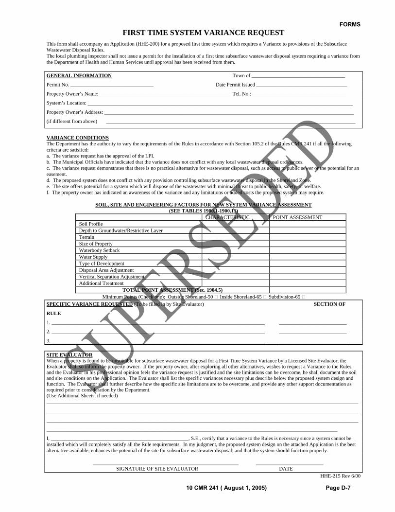
FORMS
10 CMR 241 ( August 1, 2005) Page D-7
FIRST TIME SYSTEM VARIANCE REQUEST This form shall accompany an Application (HHE-200) for a proposed first time system which requires a Variance to provisions of the Subsurface Wastewater Disposal Rules. The local plumbing inspector shall not issue a permit for the installation of a first time subsurface wastewater disposal system requiring a variance from the Department of Health and Human Services until approval has been received from them.
GENERAL INFORMATION Town of ____________________________________
Permit No. ________________________________ Date Permit Issued ___________________________________
Property Owner’s Name: __________________________________________________ Tel. No.: ____________________________________
System’s Location: ______________________________________________________________________________________________________
Property Owner’s Address: ________________________________________________________________________________________________
(if different from above) ________________________________________________________________________________________________
VARIANCE CONDITIONS The Department has the authority to vary the requirements of the Rules in accordance with Section 105.2 of the Rules CMR 241 if all the following criteria are satisfied: a. The variance request has the approval of the LPI. b. The Municipal Officials have indicated that the variance does not conflict with any local wastewater disposal ordinances. c. The variance request demonstrates that there is no practical alternative for wastewater disposal, such as access to public sewer or the potential for an easement. d. The proposed system does not conflict with any provision controlling subsurface wastewater disposal in the Shoreland Zone. e. The site offers potential for a system which will dispose of the wastewater with minimal threat to public health, safety, or welfare. f. The property owner has indicated an awareness of the variance and any limitations or added costs the proposed system may require.
SOIL, SITE AND ENGINEERING FACTORS FOR NEW SYSTEM VARIANCE ASSESSMENT (SEE TABLES 1900.1-1900.11)
CHARACTERISTIC POINT ASSESSMENT Soil Profile Depth to Groundwater/Restrictive Layer Terrain Size of Property Waterbody Setback Water Supply Type of Development Disposal Area Adjustment Vertical Separation Adjustment Additional Treatment
TOTAL POINT ASSESSMENT (Sec. 1904.5) Minimum Points (Check one): Outside Shoreland-50 Inside Shoreland-65 Subdivision-65
SPECIFIC VARIANCE REQUESTED (To be filled in by Site Evaluator) SECTION OF
RULE
1. __________________________________________________________________________________ __________________________
2. __________________________________________________________________________________ __________________________
3. __________________________________________________________________________________ __________________________
SITE EVALUATOR When a property is found to be unsuitable for subsurface wastewater disposal for a First Time System Variance by a Licensed Site Evaluator, the Evaluator shall so inform the property owner. If the property owner, after exploring all other alternatives, wishes to request a Variance to the Rules, and the Evaluator in his professional opinion feels the variance request is justified and the site limitations can be overcome, he shall document the soil and site conditions on the Application. The Evaluator shall list the specific variances necessary plus describe below the proposed system design and function. The Evaluator shall further describe how the specific site limitations are to be overcome, and provide any other support documentation as required prior to consideration by the Department. (Use Additional Sheets, if needed) ________________________________________________________________________________________________________________________
________________________________________________________________________________________________________________________
________________________________________________________________________________________________________________________
________________________________________________________________________________________________________________
I, _____________________________________________________, S.E., certify that a variance to the Rules is necessary since a system cannot be installed which will completely satisfy all the Rule requirements. In my judgment, the proposed system design on the attached Application is the best alternative available; enhances the potential of the site for subsurface wastewater disposal; and that the system should function properly. ________________________________________________________ __________________________ SIGNATURE OF SITE EVALUATOR DATE
HHE-215 Rev 6/00
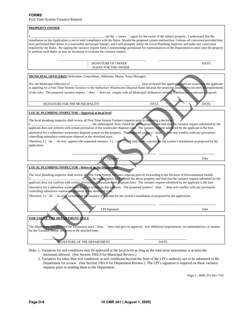
FORMS
Page D-8 10 CMR 241 ( August 1, 2005)
First Time System Variance Request
PROPERTY OWNER
I, _____________________________________________, am the owner agent for the owner of the subject property. I understand that the installation on the Application is not in total compliance with the Rules. Should the proposed system malfunction, I release all concerned provided they have performed their duties in a reasonable and proper manner, and I will promptly notify the Local Plumbing Inspector and make any corrections required by the Rules. By signing the variance request form, I acknowledge permission for representatives of the Department to enter onto the property to perform such duties as may be necessary to evaluate the variance request. _______________________________________________________ ___________________________________ SIGNATURE OF OWNER DATE AGENT FOR THE OWNER
MUNICIPAL OFFICER(S) (Selectman, Councilman, Alderman, Mayor, Town Manager) We, the Municipal Officer(s) of ____________________________________________ have reviewed this application and are aware that the applicant is applying for a First Time System Variance to the Subsurface Wastewater Disposal Rules because the proposed system does not meet all requirements
of the rules. The proposed variance request does does not comply with all Municipal Ordinances relating to subsurface wastewater disposal. _____________________________________________________ ______________________________ __________________________ SIGNATURE FOR THE MUNICIPALITY TITLE DATE
LOCAL PLUMBING INSPECTOR - Approval at local level The local plumbing inspector shall review all First Time System Variance requests prior to rendering a decision. I, _____________________________________, the undersigned, have visited the above property and find that the variance request submitted by the applicant does not conform with certain provisions of the wastewater disposal rules. The variance request submitted by the applicant is the best
alternative for a subsurface wastewater disposal system on this property. The proposed system ( does does not) conflict with any provisions controlling subsurface wastewater disposal in the shoreland zone.
Therefore, I ( do do not) approve the requested variance. I ( will will not) issue a permit for the system’s installation as proposed by the application. ____________________________________________________ ___________________________________
LPI Signature Date
LOCAL PLUMBING INSPECTOR - Referral to the Department The local plumbing inspector shall review all First Time System Variance requests prior to forwarding to the Division of Environmental Health. I, _____________________________________, the undersigned, have visited the above property and find that the variance request submitted by the applicant does not conform with certain provisions of the wastewater disposal rules. The variance request submitted by the applicant is the best
alternative for a subsurface wastewater disposal system on this property. The proposed system ( does does not) conflict with any provisions controlling subsurface wastewater disposal in the shoreland zone.
Therefore, I ( do do not) recommend the issuance of a permit for the system’s installation as proposed by the application. ____________________________________________________ ___________________________________
LPI Signature Date
FOR USE BY THE DEPARTMENT ONLY
The Department has reviewed the variance(s) and ( does does not) give its approval. Any additional requirements, recommendations, or reasons for the Variance denial, are given in the attached letter. ________________________________________________________ __________________________ SIGNATURE OF THE DEPARTMENT DATE
Note: 1. Variances for soil conditions may be approved at the local level as long as the total point assessment is at least the minimum allowed. (See Section 1902.0 for Municipal Review.) 2. Variances for other than soil conditions or soil conditions beyond the limit of the LPI’s authority are to be submitted to the
Department for review. (See Section 1901.0 for Department Review.) The LPI’s signature is required on these variance requests prior to sending them to the Department.
Page 2 - HHE-215 Rev 7/05
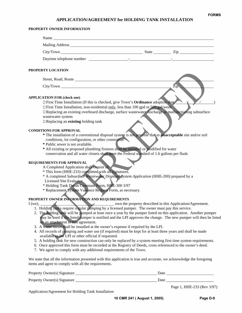
FORMS
10 CMR 241 ( August 1, 2005) Page D-9
APPLICATION/AGREEMENT for HOLDING TANK INSTALLATION
PROPERTY OWNER INFORMATION Name
Mailing Address
City/Town State Zip
Daytime telephone number - -
PROPERTY LOCATION Street, Road, Route
City/Town Zip
APPLICATION FOR (check one) First Time Installation (If this is checked, give Town’s Ordinance adoption date / / ) First Time Installation, non-residential only, less than 100 gpd or 500 gal/week
Replacing an existing overboard discharge, surface wastewater discharge or malfunctioning subsurface wastewater system
Replacing an existing holding tank CONDITIONS FOR APPROVAL * The installation of a conventional disposal system is not possible due to unacceptable site and/or soil conditions, lot configuration, or other constraints * Public sewer is not available. * All existing or proposed plumbing fixtures shall be installed or modified for water conservation and all water closets shall meet the Federal standard of 1.6 gallons per flush. REQUIREMENTS FOR APPROVAL A Completed Application shall consist of: * This form (HHE-233) completed with all signatures. * A completed Subsurface Wastewater Disposal System Application (HHE-200) prepared by a Licensed Site Evaluator. * Holding Tank Deeds Covenant Form, HHE-300 3/97 * Replacement System Variance Request Form, as necessary. PROPERTY OWNER INFORMATION AND REQUIREMENTS I (we), own the property described in this Application/Agreement.
1. Holding tanks require regular pumping by a licensed pumper. The owner must pay this service. 2. The holding tank will be pumped at least once a year by the pumper listed on this application. Another pumper
may be used if the listed pumper is notified and the LPI approves the change. The new pumper will then be listed on an attachment to this agreement.
3. A water meter shall be installed at the owner’s expense if required by the LPI. 4. All records of pumping and water use (if required) must be kept for at least three years and shall be made
available to the LPI or other official if requested. 5. A holding tank for new construction can only be replaced by a system meeting first time system requirements. 6. Once approved this form must be recorded at the Registry of Deeds, cross referenced to the owner’s deed. 7. We agree to comply with any additional requirements of the Town.
We state that all the information presented with this application is true and accurate, we acknowledge the foregoing items and agree to comply with all the requirements.
Property Owner(s) Signature Date
Property Owner(s) Signature Date
Page 1, HHE-233 (Rev 3/97) Application/Agreement for Holding Tank Installation
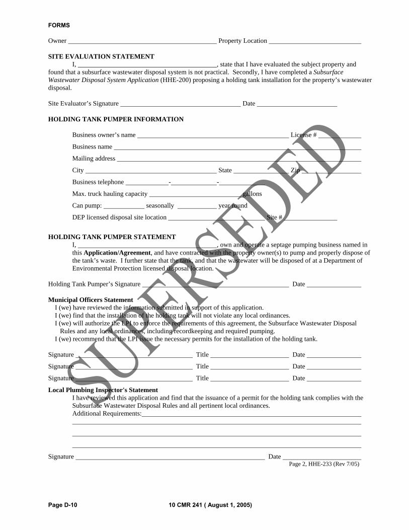
FORMS
Page D-10 10 CMR 241 ( August 1, 2005)
Owner Property Location SITE EVALUATION STATEMENT I, , state that I have evaluated the subject property and found that a subsurface wastewater disposal system is not practical. Secondly, I have completed a Subsurface Wastewater Disposal System Application (HHE-200) proposing a holding tank installation for the property’s wastewater disposal. Site Evaluator’s Signature Date HOLDING TANK PUMPER INFORMATION Business owner’s name License #
Business name
Mailing address
City State Zip
Business telephone - -
Max. truck hauling capacity gallons
Can pump: seasonally year round
DEP licensed disposal site location Site #
HOLDING TANK PUMPER STATEMENT
I, , own and operate a septage pumping business named in this Application/Agreement, and have contracted with the property owner(s) to pump and properly dispose of the tank’s waste. I further state that the tank, and that the wastewater will be disposed of at a Department of Environmental Protection licensed disposal location.
Holding Tank Pumper’s Signature Date Municipal Officers Statement I (we) have reviewed the information submitted in support of this application. I (we) find that the installation of the holding tank will not violate any local ordinances. I (we) will authorize the LPI to enforce the requirements of this agreement, the Subsurface Wastewater Disposal Rules and any local ordinances, including recordkeeping and required pumping. I (we) recommend that the LPI issue the necessary permits for the installation of the holding tank. Signature Title Date
Signature Title Date
Signature Title Date
Local Plumbing Inspector's Statement I have reviewed this application and find that the issuance of a permit for the holding tank complies with the Subsurface Wastewater Disposal Rules and all pertinent local ordinances.
Additional Requirements:
Signature Date Page 2, HHE-233 (Rev 7/05)
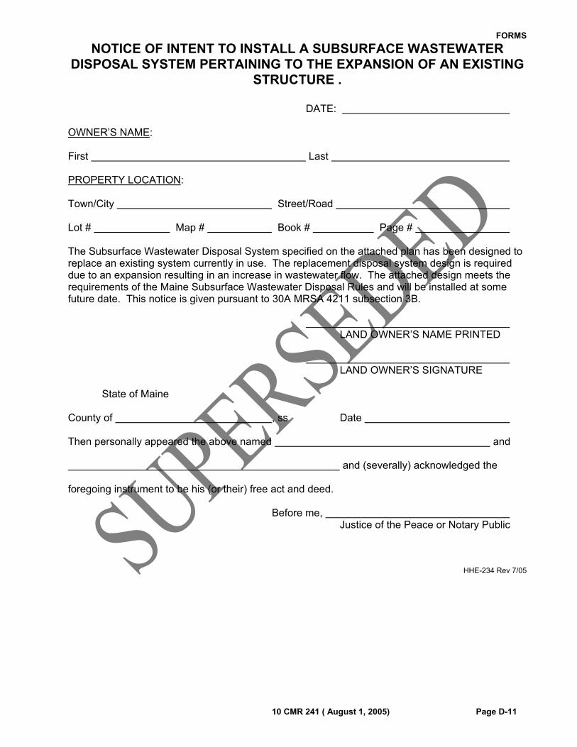
FORMS
10 CMR 241 ( August 1, 2005) Page D-11
NOTICE OF INTENT TO INSTALL A SUBSURFACE WASTEWATER DISPOSAL SYSTEM PERTAINING TO THE EXPANSION OF AN EXISTING
STRUCTURE .
DATE: OWNER’S NAME: First Last PROPERTY LOCATION: Town/City Street/Road Lot # Map # Book # Page # The Subsurface Wastewater Disposal System specified on the attached plan has been designed to replace an existing system currently in use. The replacement disposal system design is required due to an expansion resulting in an increase in wastewater flow. The attached design meets the requirements of the Maine Subsurface Wastewater Disposal Rules and will be installed at some future date. This notice is given pursuant to 30A MRSA 4211 subsection 3B. LAND OWNER’S NAME PRINTED LAND OWNER’S SIGNATURE State of Maine County of , ss Date Then personally appeared the above named and and (severally) acknowledged the foregoing instrument to be his (or their) free act and deed. Before me, Justice of the Peace or Notary Public
HHE-234 Rev 7/05
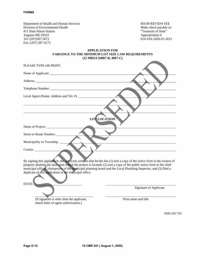
FORMS
Page D-12 10 CMR 241 ( August 1, 2005)
Department of Health and Human Services $50.00 REVIEW FEE Division of Environmental Health Make check payable to: #11 State House Station “Treasurer of State” Augusta ME 04333 Appropriation # Tel: (207)287-5672 014-10A-2426-01-2615 Fax: (207) 287-4172
APPLICATION FOR VARIANCE TO THE MINIMUM LOT SIZE LAW REQUIREMENTS
(12 MRSA §4807-B, 4807-C) PLEASE TYPE OR PRINT: Name of Applicant: Address: Telephone Number: Local Agent (Name, Address and Tel. #)
LOT LOCATION
Name of Project: Street or Route Number: Municipality or Township: County: By signing this application, the applicant certifies that he/she has (1) sent a copy of the notice form to the owners of property abutting the land upon which the project is located; (2) sent a copy of the public notice form to the chief municipal officer, chairperson of the municipal planning board and the Local Plumbing Inspector, and (3) filed a duplicate of this application in the municipal office. DATE: Signature of Applicant (If signature is other than the applicant, Print name and title attach letter of agent authorization.)
HHE-236 7/05
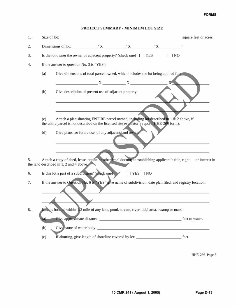
FORMS
10 CMR 241 ( August 1, 2005) Page D-13
PROJECT SUMMARY - MINIMUM LOT SIZE 1. Size of lot: square feet or acres. 2. Dimensions of lot: ‘ X ‘ X ‘ X ‘ 3. Is the lot owner the owner of adjacent property? (check one) [ ] YES [ ] NO 4. If the answer to question No. 3 is “YES”: (a) Give dimensions of total parcel owned, which includes the lot being applied for: X X X (b) Give description of present use of adjacent property: (c) Attach a plan showing ENTIRE parcel owned, including lot described in 1 & 2 above, if the entire parcel is not described on the licensed site evaluator’s report (HHE-200 form). (d) Give plans for future use, of any adjacent land owned: 5. Attach a copy of deed, lease, option or other legal document establishing applicant’s title, right or interest in the land described in 1, 2 and 4 above. 6. Is this lot a part of a subdivision? (check one) [ ] YES [ ] NO 7. If the answer to Question No. 6 is “YES” give name of subdivision, date plan filed, and registry location: 8. If lot is located within 1/2 mile of any lake, pond, stream, river, tidal area, swamp or marsh: (a) Give approximate distance: feet to water. (b) Give name of water body: (c) If abutting, give length of shoreline covered by lot: feet.
HHE-236 Page 3
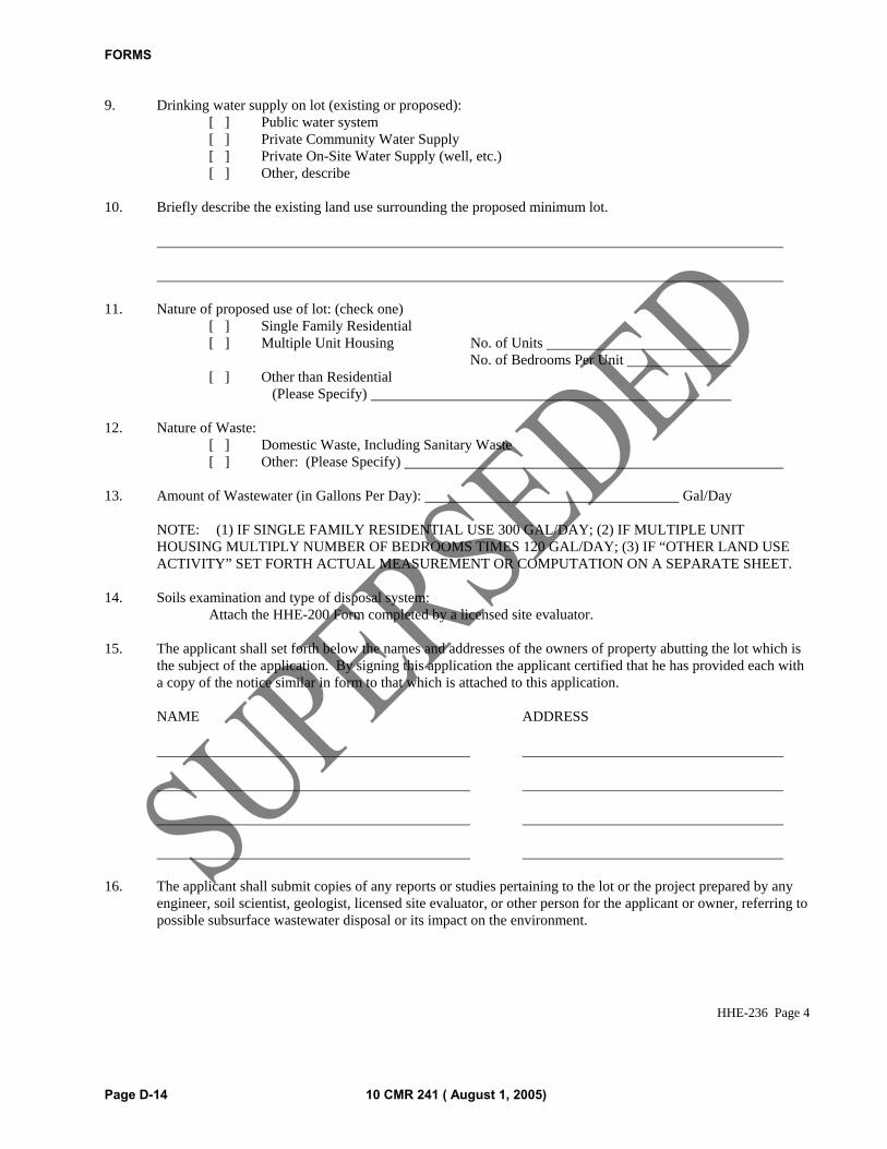
FORMS
Page D-14 10 CMR 241 ( August 1, 2005)
9. Drinking water supply on lot (existing or proposed): [ ] Public water system [ ] Private Community Water Supply [ ] Private On-Site Water Supply (well, etc.) [ ] Other, describe 10. Briefly describe the existing land use surrounding the proposed minimum lot. 11. Nature of proposed use of lot: (check one) [ ] Single Family Residential [ ] Multiple Unit Housing No. of Units No. of Bedrooms Per Unit [ ] Other than Residential (Please Specify) 12. Nature of Waste: [ ] Domestic Waste, Including Sanitary Waste [ ] Other: (Please Specify) 13. Amount of Wastewater (in Gallons Per Day): Gal/Day NOTE: (1) IF SINGLE FAMILY RESIDENTIAL USE 300 GAL/DAY; (2) IF MULTIPLE UNIT
HOUSING MULTIPLY NUMBER OF BEDROOMS TIMES 120 GAL/DAY; (3) IF “OTHER LAND USE ACTIVITY” SET FORTH ACTUAL MEASUREMENT OR COMPUTATION ON A SEPARATE SHEET.
14. Soils examination and type of disposal system: Attach the HHE-200 Form completed by a licensed site evaluator. 15. The applicant shall set forth below the names and addresses of the owners of property abutting the lot which is
the subject of the application. By signing this application the applicant certified that he has provided each with a copy of the notice similar in form to that which is attached to this application.
NAME ADDRESS 16. The applicant shall submit copies of any reports or studies pertaining to the lot or the project prepared by any
engineer, soil scientist, geologist, licensed site evaluator, or other person for the applicant or owner, referring to possible subsurface wastewater disposal or its impact on the environment.
HHE-236 Page 4
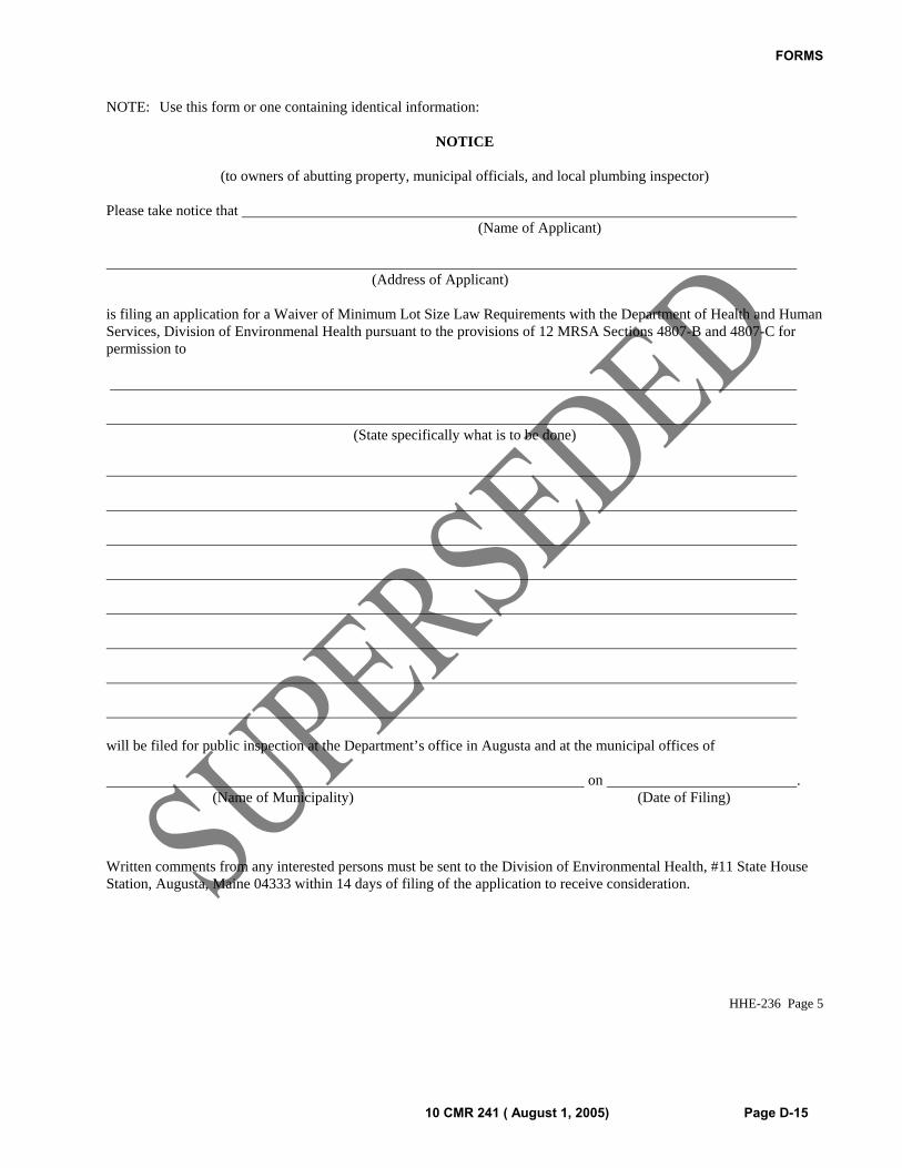
FORMS
10 CMR 241 ( August 1, 2005) Page D-15
NOTE: Use this form or one containing identical information:
NOTICE
(to owners of abutting property, municipal officials, and local plumbing inspector) Please take notice that (Name of Applicant)
(Address of Applicant) is filing an application for a Waiver of Minimum Lot Size Law Requirements with the Department of Health and Human Services, Division of Environmenal Health pursuant to the provisions of 12 MRSA Sections 4807-B and 4807-C for permission to
(State specifically what is to be done)
will be filed for public inspection at the Department’s office in Augusta and at the municipal offices of on . (Name of Municipality) (Date of Filing) Written comments from any interested persons must be sent to the Division of Environmental Health, #11 State House Station, Augusta, Maine 04333 within 14 days of filing of the application to receive consideration.
HHE-236 Page 5
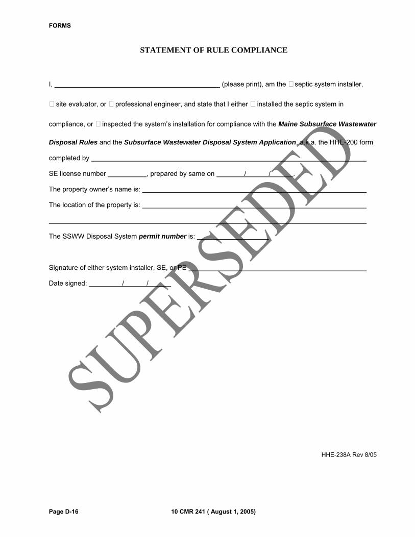
FORMS
Page D-16 10 CMR 241 ( August 1, 2005)
STATEMENT OF RULE COMPLIANCE
I, (please print), am the septic system installer,
site evaluator, or professional engineer, and state that I either installed the septic system in
compliance, or inspected the system’s installation for compliance with the Maine Subsurface Wastewater
Disposal Rules and the Subsurface Wastewater Disposal System Application, a.k.a. the HHE-200 form
completed by
SE license number , prepared by same on / / .
The property owner’s name is:
The location of the property is:
The SSWW Disposal System permit number is:
Signature of either system installer, SE, or PE
Date signed: / /
HHE-238A Rev 8/05
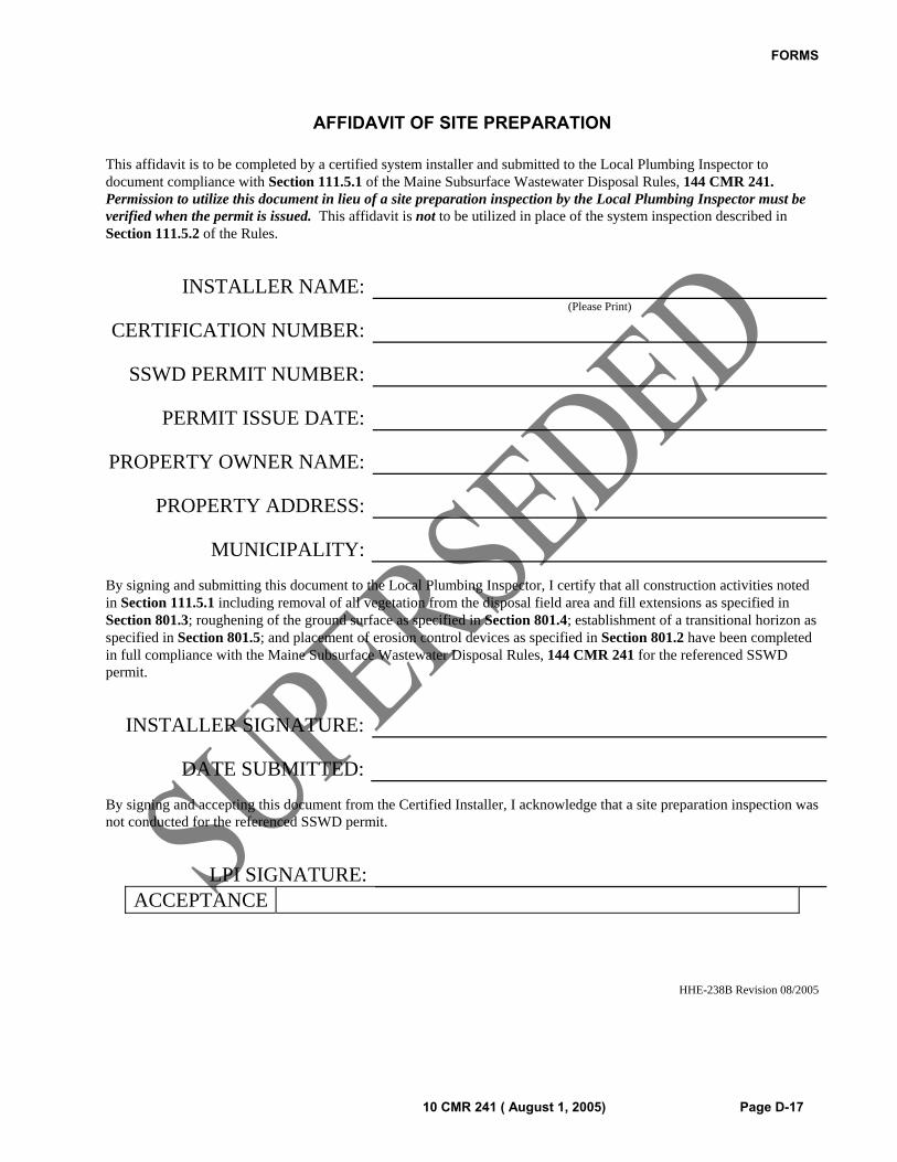
FORMS
10 CMR 241 ( August 1, 2005) Page D-17
AFFIDAVIT OF SITE PREPARATION
This affidavit is to be completed by a certified system installer and submitted to the Local Plumbing Inspector to document compliance with Section 111.5.1 of the Maine Subsurface Wastewater Disposal Rules, 144 CMR 241. Permission to utilize this document in lieu of a site preparation inspection by the Local Plumbing Inspector must be verified when the permit is issued. This affidavit is not to be utilized in place of the system inspection described in Section 111.5.2 of the Rules.
INSTALLER NAME:
CERTIFICATION NUMBER:(Please Print)
SSWD PERMIT NUMBER:
PERMIT ISSUE DATE:
PROPERTY OWNER NAME:
PROPERTY ADDRESS:
MUNICIPALITY:
By signing and submitting this document to the Local Plumbing Inspector, I certify that all construction activities noted in Section 111.5.1 including removal of all vegetation from the disposal field area and fill extensions as specified in Section 801.3; roughening of the ground surface as specified in Section 801.4; establishment of a transitional horizon as specified in Section 801.5; and placement of erosion control devices as specified in Section 801.2 have been completed in full compliance with the Maine Subsurface Wastewater Disposal Rules, 144 CMR 241 for the referenced SSWD permit.
INSTALLER SIGNATURE:
DATE SUBMITTED:
By signing and accepting this document from the Certified Installer, I acknowledge that a site preparation inspection was not conducted for the referenced SSWD permit.
LPI SIGNATURE:
ACCEPTANCE
HHE-238B Revision 08/2005
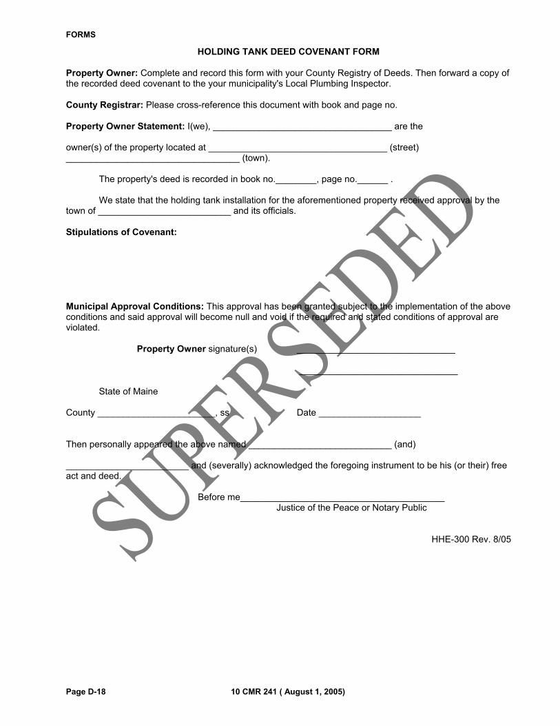
FORMS
Page D-18 10 CMR 241 ( August 1, 2005)
HOLDING TANK DEED COVENANT FORM Property Owner: Complete and record this form with your County Registry of Deeds. Then forward a copy of the recorded deed covenant to the your municipality's Local Plumbing Inspector. County Registrar: Please cross-reference this document with book and page no. Property Owner Statement: I(we), ___________________________________ are the owner(s) of the property located at ___________________________________ (street) __________________________________ (town). The property's deed is recorded in book no.________, page no.______ . We state that the holding tank installation for the aforementioned property received approval by the town of __________________________ and its officials. Stipulations of Covenant: Municipal Approval Conditions: This approval has been granted subject to the implementation of the above conditions and said approval will become null and void if the required and stated conditions of approval are violated. Property Owner signature(s) _______________________________ _______________________________ State of Maine County _______________________, ss Date ____________________ Then personally appeared the above named ____________________________ (and) ________________________ and (severally) acknowledged the foregoing instrument to be his (or their) free act and deed. Before me________________________________________ Justice of the Peace or Notary Public
HHE-300 Rev. 8/05
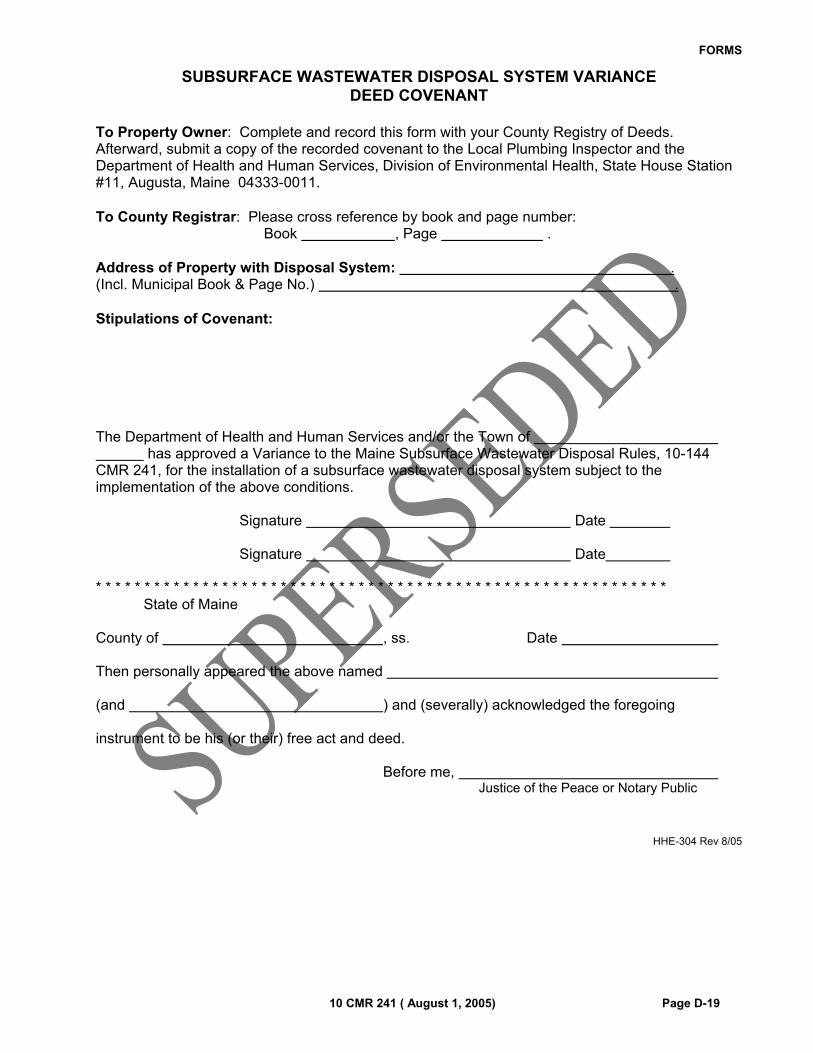
FORMS
10 CMR 241 ( August 1, 2005) Page D-19
SUBSURFACE WASTEWATER DISPOSAL SYSTEM VARIANCE DEED COVENANT
To Property Owner: Complete and record this form with your County Registry of Deeds. Afterward, submit a copy of the recorded covenant to the Local Plumbing Inspector and the Department of Health and Human Services, Division of Environmental Health, State House Station #11, Augusta, Maine 04333-0011. To County Registrar: Please cross reference by book and page number: Book , Page . Address of Property with Disposal System: . (Incl. Municipal Book & Page No.) . Stipulations of Covenant: The Department of Health and Human Services and/or the Town of has approved a Variance to the Maine Subsurface Wastewater Disposal Rules, 10-144 CMR 241, for the installation of a subsurface wastewater disposal system subject to the implementation of the above conditions. Signature Date Signature Date * * * * * * * * * * * * * * * * * * * * * * * * * * * * * * * * * * * * * * * * * * * * * * * * * * * * * * * * * * * State of Maine County of , ss. Date Then personally appeared the above named (and ) and (severally) acknowledged the foregoing instrument to be his (or their) free act and deed. Before me, Justice of the Peace or Notary Public
HHE-304 Rev 8/05
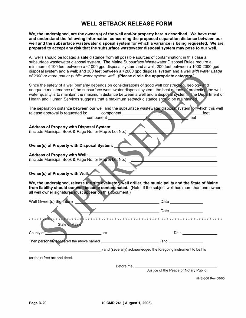
Page D-20 10 CMR 241 ( August 1, 2005)
WELL SETBACK RELEASE FORM
We, the undersigned, are the owner(s) of the well and/or property herein described. We have read and understand the following information concerning the proposed separation distance between our well and the subsurface wastewater disposal system for which a variance is being requested. We are prepared to accept any risk that the subsurface wastewater disposal system may pose to our well. All wells should be located a safe distance from all possible sources of contamination; in this case a subsurface wastewater disposal system. The Maine Subsurface Wastewater Disposal Rules require a minimum of 100 feet between a <1000 gpd disposal system and a well; 200 feet between a 1000-2000 gpd disposal system and a well; and 300 feet between a >2000 gpd disposal system and a well with water usage of 2000 or more gpd or public water system well. (Please circle the appropriate category.) Since the safety of a well primarily depends on considerations of good well construction, geology and adequate maintenance of the subsurface wastewater disposal system, the best means of protecting the well water quality is to maintain the maximum distance between a well and a disposal system. The Department of Health and Human Services suggests that a maximum setback distance should be maintained. The separation distance between our well and the subsurface wastewater disposal system for which this well release approval is requested is: component / feet. component / feet Address of Property with Disposal System: (Include Municipal Book & Page No. or Map & Lot No.) Owner(s) of Property with Disposal System: Address of Property with Well: (Include Municipal Book & Page No. or Map & Lot No.) Owner(s) of Property with Well: We, the undersigned, release the site evaluator, well driller, the municipality and the State of Maine from liability should our well become contaminated. (Note: If the subject well has more than one owner, all well owner signatures must appear on this document.) Well Owner(s) Signature Date Date * * * * * * * * * * * * * * * * * * * * * * * * * * * * * * * * * * * * * * * * * * * * * * * * * * * * * * * * * * * * * * * * * * * * * * * * State of Maine County of , ss Date Then personally appeared the above named (and ) and (severally) acknowledged the foregoing instrument to be his (or their) free act and deed. Before me, Justice of the Peace or Notary Public
HHE-306 Rev 08/05

10 CMR 241 ( August 1, 2005) Page D-21
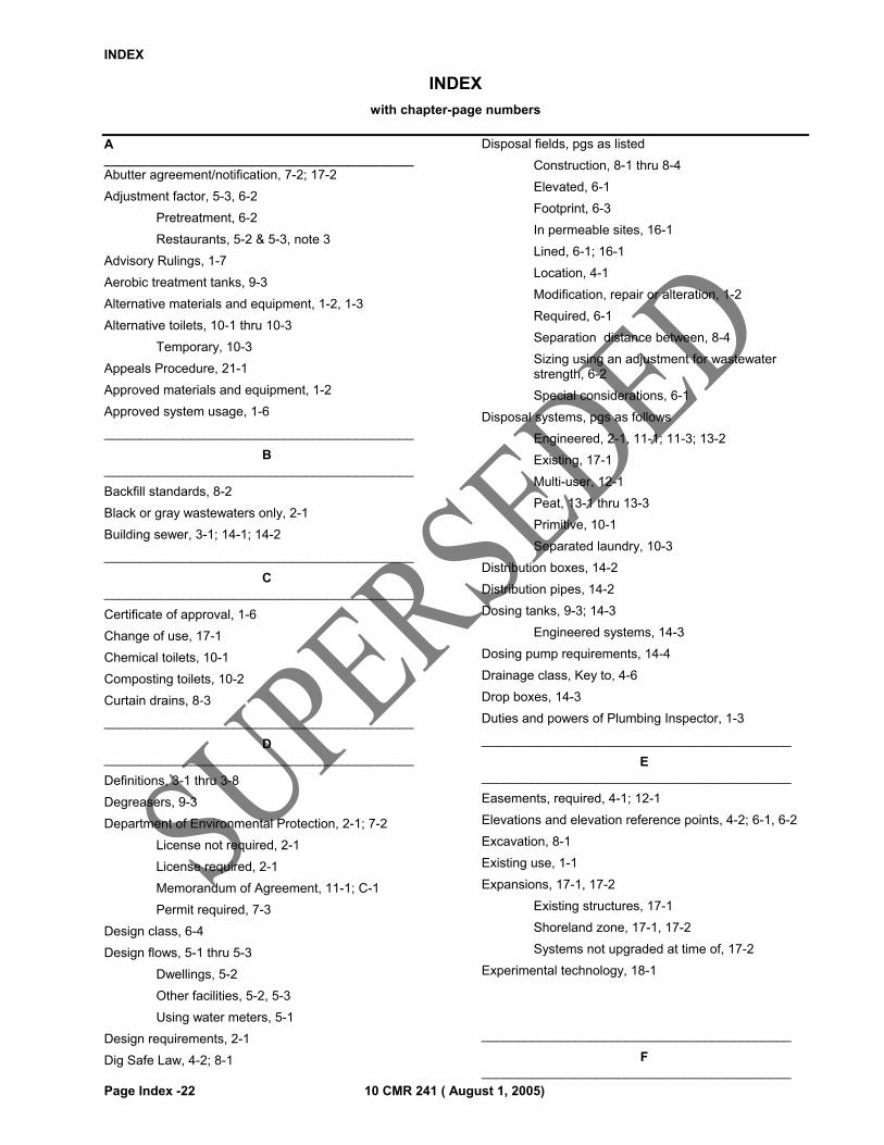
INDEX
Page Index -22 10 CMR 241 ( August 1, 2005)
INDEX
with chapter-page numbers
A ___________________________________________ Abutter agreement/notification, 7-2; 17-2
Adjustment factor, 5-3, 6-2
Pretreatment, 6-2
Restaurants, 5-2 & 5-3, note 3
Advisory Rulings, 1-7
Aerobic treatment tanks, 9-3
Alternative materials and equipment, 1-2, 1-3
Alternative toilets, 10-1 thru 10-3
Temporary, 10-3
Appeals Procedure, 21-1
Approved materials and equipment, 1-2
Approved system usage, 1-6
___________________________________________
B ___________________________________________
Backfill standards, 8-2
Black or gray wastewaters only, 2-1
Building sewer, 3-1; 14-1; 14-2
___________________________________________
C ___________________________________________
Certificate of approval, 1-6
Change of use, 17-1
Chemical toilets, 10-1
Composting toilets, 10-2
Curtain drains, 8-3
___________________________________________
D ___________________________________________
Definitions, 3-1 thru 3-8
Degreasers, 9-3
Department of Environmental Protection, 2-1; 7-2
License not required, 2-1
License required, 2-1
Memorandum of Agreement, 11-1; C-1
Permit required, 7-3
Design class, 6-4
Design flows, 5-1 thru 5-3
Dwellings, 5-2
Other facilities, 5-2, 5-3
Using water meters, 5-1
Design requirements, 2-1
Dig Safe Law, 4-2; 8-1
Disposal fields, pgs as listed
Construction, 8-1 thru 8-4
Elevated, 6-1
Footprint, 6-3
In permeable sites, 16-1
Lined, 6-1; 16-1
Location, 4-1
Modification, repair or alteration, 1-2
Required, 6-1
Separation distance between, 8-4
Sizing using an adjustment for wastewater strength, 6-2
Special considerations, 6-1
Disposal systems, pgs as follows
Engineered, 2-1, 11-1; 11-3; 13-2
Existing, 17-1
Multi-user, 12-1
Peat, 13-1 thru 13-3
Primitive, 10-1
Separated laundry, 10-3
Distribution boxes, 14-2
Distribution pipes, 14-2
Dosing tanks, 9-3; 14-3
Engineered systems, 14-3
Dosing pump requirements, 14-4
Drainage class, Key to, 4-6
Drop boxes, 14-3
Duties and powers of Plumbing Inspector, 1-3
___________________________________________
E ___________________________________________
Easements, required, 4-1; 12-1
Elevations and elevation reference points, 4-2; 6-1, 6-2
Excavation, 8-1
Existing use, 1-1
Expansions, 17-1, 17-2
Existing structures, 17-1
Shoreland zone, 17-1, 17-2
Systems not upgraded at time of, 17-2
Experimental technology, 18-1
___________________________________________
F ___________________________________________
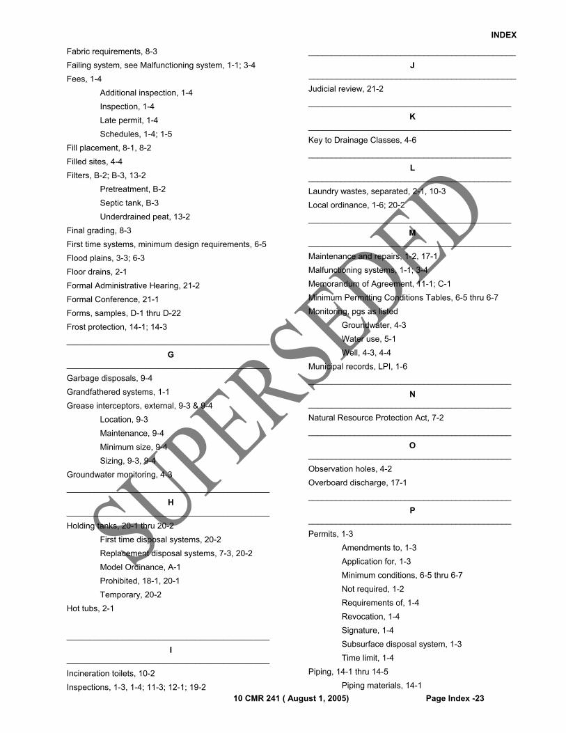
INDEX
10 CMR 241 ( August 1, 2005) Page Index -23
Fabric requirements, 8-3
Failing system, see Malfunctioning system, 1-1; 3-4
Fees, 1-4
Additional inspection, 1-4
Inspection, 1-4
Late permit, 1-4
Schedules, 1-4; 1-5
Fill placement, 8-1, 8-2
Filled sites, 4-4
Filters, B-2; B-3, 13-2
Pretreatment, B-2
Septic tank, B-3
Underdrained peat, 13-2
Final grading, 8-3
First time systems, minimum design requirements, 6-5
Flood plains, 3-3; 6-3
Floor drains, 2-1
Formal Administrative Hearing, 21-2
Formal Conference, 21-1
Forms, samples, D-1 thru D-22
Frost protection, 14-1; 14-3
____________________________________________
G ____________________________________________
Garbage disposals, 9-4
Grandfathered systems, 1-1
Grease interceptors, external, 9-3 & 9-4
Location, 9-3
Maintenance, 9-4
Minimum size, 9-4
Sizing, 9-3, 9-4
Groundwater monitoring, 4-3
____________________________________________
H ____________________________________________
Holding tanks, 20-1 thru 20-2
First time disposal systems, 20-2
Replacement disposal systems, 7-3, 20-2
Model Ordinance, A-1
Prohibited, 18-1, 20-1
Temporary, 20-2
Hot tubs, 2-1
____________________________________________
I ____________________________________________
Incineration toilets, 10-2
Inspections, 1-3, 1-4; 11-3; 12-1; 19-2
_____________________________________________
J _____________________________________________
Judicial review, 21-2
____________________________________________
K ____________________________________________
Key to Drainage Classes, 4-6
____________________________________________
L ____________________________________________
Laundry wastes, separated, 2-1, 10-3
Local ordinance, 1-6; 20-2
____________________________________________
M ____________________________________________
Maintenance and repairs, 1-2, 17-1
Malfunctioning systems, 1-1; 3-4
Memorandum of Agreement, 11-1; C-1
Minimum Permitting Conditions Tables, 6-5 thru 6-7
Monitoring, pgs as listed
Groundwater, 4-3
Water use, 5-1
Well, 4-3, 4-4
Municipal records, LPI, 1-6
____________________________________________
N ____________________________________________
Natural Resource Protection Act, 7-2
____________________________________________
O ____________________________________________
Observation holes, 4-2
Overboard discharge, 17-1
____________________________________________
P ____________________________________________
Permits, 1-3
Amendments to, 1-3
Application for, 1-3
Minimum conditions, 6-5 thru 6-7
Not required, 1-2
Requirements of, 1-4
Revocation, 1-4
Signature, 1-4
Subsurface disposal system, 1-3
Time limit, 1-4
Piping, 14-1 thru 14-5
Piping materials, 14-1
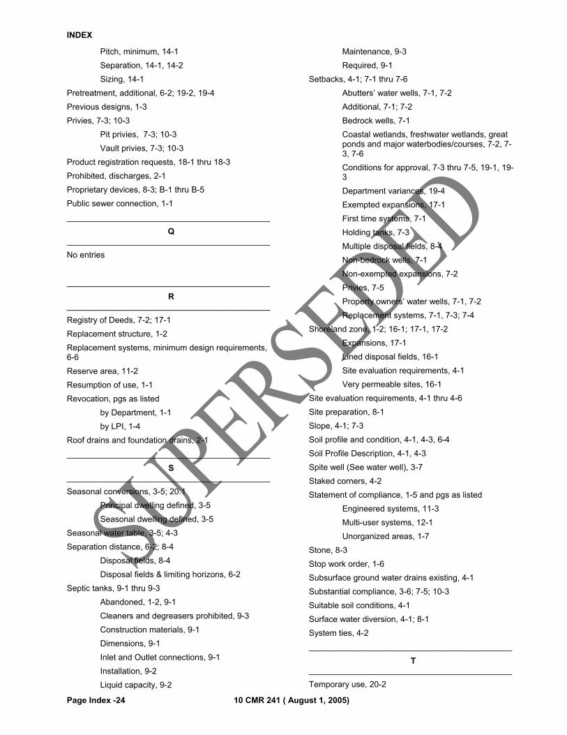
INDEX
Page Index -24 10 CMR 241 ( August 1, 2005)
Pitch, minimum, 14-1
Separation, 14-1, 14-2
Sizing, 14-1
Pretreatment, additional, 6-2; 19-2, 19-4
Previous designs, 1-3
Privies, 7-3; 10-3
Pit privies, 7-3; 10-3
Vault privies, 7-3; 10-3
Product registration requests, 18-1 thru 18-3
Prohibited, discharges, 2-1
Proprietary devices, 8-3; B-1 thru B-5
Public sewer connection, 1-1
____________________________________________
Q ____________________________________________
No entries
____________________________________________
R ____________________________________________
Registry of Deeds, 7-2; 17-1
Replacement structure, 1-2
Replacement systems, minimum design requirements, 6-6
Reserve area, 11-2
Resumption of use, 1-1
Revocation, pgs as listed
by Department, 1-1
by LPI, 1-4
Roof drains and foundation drains, 2-1
____________________________________________
S ____________________________________________
Seasonal conversions, 3-5; 20.1
Principal dwelling defined, 3-5
Seasonal dwelling defined, 3-5
Seasonal water table, 3-5; 4-3
Separation distance, 6-2; 8-4
Disposal fields, 8-4
Disposal fields & limiting horizons, 6-2
Septic tanks, 9-1 thru 9-3
Abandoned, 1-2, 9-1
Cleaners and degreasers prohibited, 9-3
Construction materials, 9-1
Dimensions, 9-1
Inlet and Outlet connections, 9-1
Installation, 9-2
Liquid capacity, 9-2
Maintenance, 9-3
Required, 9-1
Setbacks, 4-1; 7-1 thru 7-6
Abutters’ water wells, 7-1, 7-2
Additional, 7-1; 7-2
Bedrock wells, 7-1
Coastal wetlands, freshwater wetlands, great ponds and major waterbodies/courses, 7-2, 7-3, 7-6
Conditions for approval, 7-3 thru 7-5, 19-1, 19-3
Department variances, 19-4
Exempted expansions, 17-1
First time systems, 7-1
Holding tanks, 7-3
Multiple disposal fields, 8-4
Non-bedrock wells, 7-1
Non-exempted expansions, 7-2
Privies, 7-5
Property owners’ water wells, 7-1, 7-2
Replacement systems, 7-1, 7-3; 7-4
Shoreland zone, 1-2; 16-1; 17-1, 17-2
Expansions, 17-1
Lined disposal fields, 16-1
Site evaluation requirements, 4-1
Very permeable sites, 16-1
Site evaluation requirements, 4-1 thru 4-6
Site preparation, 8-1
Slope, 4-1; 7-3
Soil profile and condition, 4-1, 4-3, 6-4
Soil Profile Description, 4-1, 4-3
Spite well (See water well), 3-7
Staked corners, 4-2
Statement of compliance, 1-5 and pgs as listed
Engineered systems, 11-3
Multi-user systems, 12-1
Unorganized areas, 1-7
Stone, 8-3
Stop work order, 1-6
Subsurface ground water drains existing, 4-1
Substantial compliance, 3-6; 7-5; 10-3
Suitable soil conditions, 4-1
Surface water diversion, 4-1; 8-1
System ties, 4-2
____________________________________________
T ____________________________________________
Temporary use, 20-2
INDEX
10 CMR 241 ( August 1, 2005) Page Index -25
Transitional horizon, 8-11____________________________________________
U ____________________________________________
Unorganized areas, 1-7
Unsafe conditions, 1-6
____________________________________________
V ____________________________________________
Variances, 19-1 thru 19-4
Department setback, 7-1; 7-2
First time system, 19-1 thru 19-4
By the Department, 19-1
By the Municipality, 19-1; 19-2
Replacement systems, 19-1; 19-3
Venting, 10-1; 14-5
Very permeable sites, 16-1
Violations, 1-5
____________________________________________
W ____________________________________________
Waste discharge license, 2-1
Wastewater strength adjustment factors, 6-1
Water meters, 5-1
Weather conditions, 8-1
Wetlands, 15-1 thru 15-2
Delineation, 15-1
Disposal system installed, 15-1
Erosion control barriers, 15-2
Permit by rule, 15-1
Permits required, 15-1
Soil disturbance within 100 ft, 15-1
Work adjacent to, 15-1
____________________________________________
XYZ ____________________________________________
No entries