maintenance manual - flypipistrel.comflypipistrel.com/manuals/alpha-electro-mm.pdf · maintenance...
TRANSCRIPT

Maintenance Manualapplies to all ALPHA Electro aircraft equipped with 60 kW electric motor
WARNING!
© Copyright Pipistrel LSA s.r.l., Via Aquileia 75, 34170 Gorizia, Italy, EU
This publication includes the material required to be furnished to the pilotby ASTM F2245, F2483, F2295 and F2564.
REVISION A00(12th July, 2017)
Aircraft Registration Number:
Aircraft Serial Number:
2 Maintenance manual www.pipistrel.euREV. 0
CoverageThe Maintenance manual (MM) is in the airplane at the time of delivery from Pipistrel LSA s.r.l. con-tains information applicable to the range of Pipistrel LSA aircraft mentioned on the cover. All information is based on data available at the time of publication.
Supplements that cover non-standard are individual documents and may be issued or revised with-out regard to revision dates which apply to the MM itself. The Log of Effective Pages should be used to determine the status of each supplement.
Revision tracking, filing and identifyingPages to be removed or replaced in the MM are determined by the Log of Effective pages located in this section. This log contains the page number and revision level for each page within the MM. As revisions to the MM occur, the revision level on the effected pages is updated. When two pages dis-play the same page number, the page with the latest revision shall be used in the MM. The revision level on the Log Of Effective Pages shall also agree with the revision level of the page in question. Alternative to removing and/or replacing individual pages, the owner can also print out a whole new manual in its current form, which is always available from www.pipistrel.eu.
Revised material is marked with a vertical double-bar that will extend the full length of deleted, new, or revised text added to new or previously existing pages. This marker will be located adjacent to the applicable text in the marking on the outer side of the page. The same system is in place when the header, figure, or any other element inside this MM was revised. A list of revisions is located at the beginning of the Log Of Effective Pages
Warnings, Cautions and NotesSafety definitions used in the manual:
WARNING! Disregarding the following instructions leads to severe deterioration of flight safety and hazardous situations, including such resulting in injury and loss of life.
CAUTION! Disregarding the following instructions leads to serious deterioration of flight safety.
NOTE An operating procedure, technique, etc., which is considered essential to emphasize.
Tracking and reporting of service notices & airworthiness information feedback formTo receive notices and report safety concerns or service difficulties, issues and anomalies identified by the aircraft owner or maintainer during the operation or maintenance of this aircraft or to report con-tent errors in this maintenance manual then please log into the Owner’s section of the Pipistrel website where you can provide feedback of service difficulties and receive updates and information relevant to the service and airworthiness of your aircraft. A feedback form is provided there.Go to: www.pipistrel.eu and log in the top right corner of the page with:
Username: owner1 Password: ab2008

3www.pipistrel.eu Maintenance manualREV. 0
Index of revisionsThe table below indicated the Revisions, which were made from the original release to this date. Always check with your registration authority, Pipistrel USA (www.pipistrel-usa.com) or Pipistrel LSA s.r.l (www.pipistrel.eu) that you are familiar with the current release of the operation-relevant documentation, which includes this MM.
Designation Reason for Revision Release date Affected
pages Issuer
Revision A00 Initial issue 12 July 2017 - SLO.DOA.002

4 Maintenance manual www.pipistrel.euREV. 0
Log of Effective PagesUse to determine the currency and applicability of your AMM. Pages are affected by the cur-rent revision are marked in bold text in the Page Number column.
Page number Page Status Rev. number Page number Page Status Rev. numberCover Original 0 40 Original 0
2 Original 0 41 Original 03 Original 0 42 Original 04 Original 0 43 Original 05 Original 0 45 Original 0
6 Blank page - 46 Original 07 Original 0 47 Original 08 Blank page - 48 Original 09 Original 0 49 Blank page -
10 Original 0 50 Original 011 Original 0 51 Original 012 Blank page - 52 Original 013 Original 0 53 Original 014 Original 0 54 Original 015 Original 0 55 Original 016 Original 0 56 Original 017 Original 0 57 Original 018 Original 0 58 Original 019 Original 0 59 Blank page -20 Blank page - 60 Original 021 Original 0 61 Original 022 Original 0 62 Original 023 Original 0 63 Original 024 Original 025 Original 026 Original 027 Original 028 Original 029 Original 030 Original 031 Original 032 Original 033 Original 034 Original 035 Blank page -36 Original 037 Revision 3 038 Revision 3 0
39 Revision 3 0

5www.pipistrel.eu Maintenance manualREV. 0
Log of Effective Pages (continued)
Page number Page Status Rev. number Page number Page Status Rev. number
CAUTION!
This manual is valid only if it contains all of the original and revised pages listed above.
Each page to be revised must be removed, shredded and later replaced with the new, revised page in the exact same place in the manual.

6 Maintenance manual www.pipistrel.euREV. 0
This page is intentionally left blank.

7www.pipistrel.eu Maintenance manualREV. 0
Table of contents
General
Servicing the aircraft
Schematics
Repairs
Appendix

8 Maintenance manual www.pipistrel.euREV. 0
This page is intentionally left blank.

9www.pipistrel.eu Maintenance manualREV. 0
Introduction
Notes and remarks
Materials used in manufacturing process
Fastener torque values
Assembling and disassembling the aircraft
Keeping your aircraft in perfect shape
GeneralGeneral

10 Maintenance manual www.pipistrel.euREV. 0
IntroductionThis manual contains all information needed for appropriate and safe servicing of the ALPHA Electro
In case of aircraft damage or people injury resulting form disobeying instructions in the manual PIPISTREL LSA s.r.l. denies any responsibility.
All text, design, layout and graphics are owned by PIPISTREL LSA s.r.l. Therefore this manual and any of its contents may not be copied or distributed in any manner (electronic, web or printed) without the prior consent of PIPISTREL LSA s.r.l. unless they are directly related to the operation of our aircraft by an owner or his appointed maintenance authority..
IT IS MANDATORY TO CAREFULLY STUDY THIS MANUAL PRIOR TO USING/SERVICING OF THE AIRCRAFT
The owner who is also a Sport Pilot Certificate holder or their appointed maintenance providor are obliged to check for current documentation revisions before each mainte-nance event.
References to other manualsAircraft specifications, capacities and instruction on ground handling, servicing and lubrication etc. is part of the individual POH. Equipment list is also part of POH. Motor specifications are part of POH. Tyre inflation pressures are part of the POH.
Type D maintenence tasks (refer to page 22 of this document) are served with additional documen-tation available only to authorised service personnel whom had received factory traning.
Notes and remarksSafety definitions used in the manual:
WARNING! Disregarding the following instructions leads to severe deterioration of flight safety and hazardous situations, including such resulting in injury and loss of life.
CAUTION! Disregarding the following instructions leads to serious deterioration of flight safety.
NOTE An operating procedure, technique, etc., which is considered essential to emphasize.
General

11www.pipistrel.eu Maintenance manualREV. 0
Materials used in manufacturing processComposite parts are made of:
fabric: GG160, GG200, 90070, 92110, 92120, 91125, 92140, 92145, KHW200
roving: NF24
foam: 75 kg/m3 PVC 3mm, PVC 5 mm, PVC 8mm
GFK: 3 mm, 5 mm, 7 mm of thickness
paint: acrylic paint
firewall glass-aluminium sandwich
Metal parts used are:
tubes: materials: Fe0146, Fe 0147, Fe0545, Fe1430, AC 100, CR41 in LN9369
sheet metal: materials: Fe0147 in Al 3571
rods: materials: Fe 1221, Fe 4732, Č4130, Al 6082, CR41 in Al 6362
cable: AISI 316
bolts and nuts: 8/8 steel
All composite parts are made of glass, carbon and kevlar fiber manufactured by Interglas GmbH.
All parts have been tested at safety factor of a minimum 1.875.
All parts and materials used in Pipistrel LSA aircraft are also being used in the glider and general aviation industry and all comply with aviation standards.
All parts are made in moulds, therefore no shape or structural differences can occur.
All designing, manufacturing and testing complies with following regulations:• Bauvorschriften für Ultraleichtflugzeuge des Deutschen Aero Club e.V. Beauftragter des Bundes-ministeriums für Verkehr • JAR-1 microlight definition • EASA CS-22 - certain sections• EASA CS-VLA - certain sections for Slovenian market also: Pravilnik o ultralahkih napravah Republike Slovenije.
WARNING! WHEN SERVICING OR REPLACING PARTS ALWAYS USE THE SAME PART AS USED ORIGINALLY (SEE ABOVE).
Sources for Spare PartsALL OEM AND NON-OEM REPLACEMENT AND SPARE PARTS CAN BE ORDERED DIRECTLY FROM PIPISTREL, YOUR LOCAL DISTRIBUTOR / DEALER OR ONLINE THROUGH THE OWNERS SECTION USING THE IPC (Illustrated Parts Catalog) AND SPARE PARTS ORDER FORM.
Order through [email protected]
General
12 Maintenance manual www.pipistrel.euREV. 0
This page is intentionally left blank.
General

13www.pipistrel.eu Maintenance manualREV. 0
Fastener torque valuesST
AN
DA
RD A
VIA
TIO
N T
ORQ
UE
VALU
ES -
MET
RIC
SYST
EM
In t
he a
bsen
ce o
f sp
ecifi
c to
rque
val
ues,
the
fol
low
ing
char
t ca
n be
use
d as
a g
uide
to
the
max
imum
saf
e to
rque
for
a p
artic
ular
siz
e/gr
ade
of fa
sten
er.
Ther
e is
no to
rque
diff
eren
ce fo
r fin
e or
coa
rse
thre
ads.
To
rque
val
ues a
re b
ased
on
clea
n, d
ry th
read
s.
Red
uce
valu
e by
10%
if th
read
s are
oile
d be
fore
ass
embl
y Re
lativ
e St
reng
th M
arki
ng
8.8
or 9
.8
10.9
12
.9
Bolt
Mar
king
s
Diam
eter
W
renc
h Si
ze
Max
imum
Tor
que
Max
imum
Tor
que
Max
imum
Tor
que
Ft lb
N
m
Ft lb
N
m
Ft lb
N
m
M3
M4
M5
M6
M8
M10
M
12
M14
M
16
M18
M
20
M22
M
24
M27
M
30
5.5m
m
7mm
8m
m
10m
m
13m
m
16m
m
18m
m
21m
m
24m
m
27m
m
30m
m
33m
m
36m
m
41m
m
46m
m
1 2 4.5
7.5 18
37
63
103
159
225
321
435
553
811
1103
1.3 3 6 10
25
50
85
140
215
305
425
590
750
1100
14
95
1.5 3 6.5 11
26
55
97
151
232
321
457
620
789
1154
15
71
2 4.5 9 15
35
75
130
205
315
435
620
840
1070
15
65
2130
1.5 4 7.5 13
33
63
111
177
273
376
535
726
926
1353
18
37
2 5 10
18
45
85
150
240
390
510
725
985
1255
18
35
2490
General

14 Maintenance manual www.pipistrel.euREV. 0
Assembling and disassembling the aircraftCAUTION! Prior to each assembling or disassembling action the airframe must be placed inside a closed space. Under no circumstances attempt to assemble or disassemble any parts of the aircraft in the sun or at temperatures higher or as high as 75°F for you will not be able to assemble certain parts.
Assembling the wingsThree people are needed to assemble the wings to the fuselage.
First block all three wheels for the fuselage to stay in position. Clean and use lithium grease on the main wing pins and insertion openings. Inside the cockpit set the flap handle to neutral position. Make sure you have all bolts, nuts, washers and wrenches needed at a reach of a hand.
Lift one wing (one person at each end) and bring it closer to the fuselage. While the two are holding the wing-half high up, the third person directs their movement to put the wing’s main spar into the opening on the adja-cent side of the fuselage. As the wing is about 4 inches away from its final position, fit the electrical cables, fuel hose and pitot static lines through the opening.
Now push the wing-half into its final position slowly. The person closest to the fuselage must make sure the flap drive has fitted into the fu-selage fittings properly. At the same time, the person holding the wingtip must start with slight circular movements (1/2 inch each direc-tion) in order to assure a tight fit of the wing and its connectors.
As this is done the person at the wingtip must remain in position holding the wing, whereas the other two move over to the other wing, lift it and bring it closer to the fuselage. Again, all cables, hoses and lines must be fit-ted through the openings prior the wing being pushed into its final position. Do not forget to make sure the flap drive has fitted into ad-equate fittings properly on this wing as well.
Both wings should now be in their final posi-tion but still being held at wingtips. The person not holding the wings must now open the cabin door and insert both pre-greased spar pins. First insert the pin on the right-hand side
of the cockpit because of easier insertion (thin-ner spar in front), then the pin on the left-hand side of the cockpit.
If necessary, the two at the wingtips can assist by rocking the wings less than an inch.
Only when both spar pins have been inserted and secured, wingtips may be released and door fully opened and fastened to the wing.Now check all the control surface deflections for smooth, unobstructed movement.
Insert all bolts and pins (do not forget the long center bolt) and secure them with self-locking nuts. Do not forget to put aluminium washers underneath the nuts!
Spar pins and centre bolt torque = 22NM
Connect all electrical cables, fuel hoses (fixed or click-on connectors!) and pitot-static lines to their correct fittings. Check for adequate fuel flow through the fuel connectors before attempting the first flight (1 liter / 1 quart per minute). For fixed fuel connectors make sure you have tightened the metal clamp around the tube securely!
Install the pitot tube on bottom side of the right wing at approximately 2/3 of the wing-span. Be extra careful not to switch the two tubes as this causes misinterpretation of indicated airspeed!
Finally tape the gap between the fuselage and the wing using self-adhesive tape.
General

15www.pipistrel.eu Maintenance manualREV. 0
Three people again are needed to disassemble the wings.
First block all three wheels for the fuselage to stay in position. Empty both fuel tanks by opening both fuel valves inside the cockpit and the drain valve beneath the bottom of the firewall. Place a canister under the drain valve to collect fuel.
While you wait for the tanks to empty, disas-semble the horizontal tail surfaces, disconnect all electrical cables and pitot-static lines. Do not forget to unscrew the pitot tube on the bottom side of the right wing. Then, inside the cockpit, unscrew the middle main spar bolt first, then unscrew and remove both spar pin locking bolts.
WARNING! Do not remove spar pins yet!
Once the fuel tanks are empty, disconnect the fuel hoses inside the cockpit as well.
Make sure you tape the end attached to the wing not to spill any eventual leftover fuel over the fuselage or glass surfaces as substantial damage may occur.
Two people must now lift the wingtips (one wingtip each) and the person in the cock-pit remove the main spar pins, one by one, smoothly. Forcing pins out of their position may result in structural damage, therefore the wingtip holders must hold the wing precisely at certain height!
Using slight circular movement at the wingtip, the wing-halfs must now be pulled out slowly one at a time. On pulling, each wing must be held by two, one at the wingtip and one near the spar.
As the wing have been pulled out, place them onto a soft surface to prevent their damage.
Schematic of wing (dis)assembly
Disassembling the wings
General
16 Maintenance manual www.pipistrel.euREV. 0
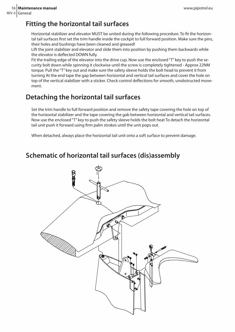
Set the trim handle to full forward position and remove the safety tape covering the hole on top of the horizontal stabilizer and the tape covering the gab between horizontal and vertical tail surfaces. Now use the enclosed “T” key to push the safety sleeve holds the bolt heat To detach the horizontal tail unit push it forward using firm palm strokes until the unit pops out.
When detached, always place the horizontal tail unit onto a soft surface to prevent damage.
Fitting the horizontal tail surfacesHorizontal stabilizer and elevator MUST be united during the following procedure. To fit the horizon-tal tail surfaces first set the trim handle inside the cockpit to full forward position. Make sure the pins, their holes and bushings have been cleaned and greased! Lift the joint stabilizer and elevator and slide them into position by pushing them backwards while the elevator is deflected DOWN fully. Fit the trailing edge of the elevator into the drive cup. Now use the enclosed “T” key to push the se-curity bolt down while spinning it clockwise until the screw is completely tightened - Approx 22NM torque. Pull the “T” key out and make sure the safety sleeve holds the bolt head to prevent it from turning At the end tape the gap between horizontal and vertical tail surfaces and cover the hole on top of the vertical stabilizer with a sticker. Check control deflections for smooth, unobstructed move-ment.
Detaching the horizontal tail surfaces
Schematic of horizontal tail surfaces (dis)assembly
General
17www.pipistrel.eu Maintenance manualREV. 0
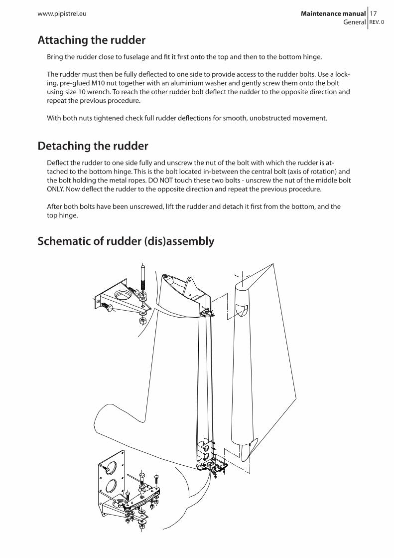
Bring the rudder close to fuselage and fit it first onto the top and then to the bottom hinge.
The rudder must then be fully deflected to one side to provide access to the rudder bolts. Use a lock-ing, pre-glued M10 nut together with an aluminium washer and gently screw them onto the bolt using size 10 wrench. To reach the other rudder bolt deflect the rudder to the opposite direction and repeat the previous procedure.
With both nuts tightened check full rudder deflections for smooth, unobstructed movement.
Detaching the rudderDeflect the rudder to one side fully and unscrew the nut of the bolt with which the rudder is at-tached to the bottom hinge. This is the bolt located in-between the central bolt (axis of rotation) and the bolt holding the metal ropes. DO NOT touch these two bolts - unscrew the nut of the middle bolt ONLY. Now deflect the rudder to the opposite direction and repeat the previous procedure.
After both bolts have been unscrewed, lift the rudder and detach it first from the bottom, and the top hinge.
Schematic of rudder (dis)assembly
Attaching the rudder
General

18 Maintenance manual www.pipistrel.euREV. 0
Keeping your aircraft in perfect shape
Precautions1) Eliminate the use of ALL aggressive cleaning solutions and organic solvents, also the window cleaning spray, benzene, acetone, aggressive shampoos etc.
2) If you must use an organic solvent (acetone) on small areas remove certain glue leftovers or simi-lar, the surface in question MUST be polished thereafter. The only section where polishing should be avoided is the edge on the wing where the wing tape is applied.
3) When flying in regions with a lot of bugs in the air, you should protect the leading edges of the airframe before flight (propeller, wings, tail) with Antistatic furniture spray cleaner: “Pronto (transpar-ent), manufacturer: Johnson Wax (or anything equivalent) – Worldwide”, approximate price is only $3 USD / €3 EUR for a 300 ml spray bottle. Using such spray, do not apply it directly onto the wing but into a soft cloth instead (old T-shirts are best). 4) After having finished with flight activity for the day, clean the leading edges of the airframe as soon as possible with a lot of water and a drying towel (chamois, artificial leather skin). This will be very easy to do if you applied a coat of Pronto before flight.
Detailed handling (Airframe cleaning instructions)
Every-day care after flightBugs, which represent the most of the dirt to be found on the airframe, are to be removed with clean water and a soft cloth (can be also drying towel, chamois, artificial leather skin). To save time, soak all the leading edges of the airframe fist. Make sure to wipe ALL of the aircraft’s surface until it is com-pletely dry.Clean the propeller and eventual grease spots separately using a mild car shampoo with a wax.
CAUTION! Do not, under any circumstances attempt to use aggressive cleaning solutions, as you will severely damage the lacquer, which is the only protective layer before the structural laminate.
When using the aircraft in difficult atmospheric conditions (intense sunshine, dusty winds, coastline, acid rains etc.) make sure to clean the outer surface more thoroughly.
If you notice you cannot remove the bug-spots from the leading edges of the aircraft, this means the lacquer is not protected any more, therefore it is necessary to polish these surfaces.
CAUTION! Do not, under any circumstances attempt to remove such bug-spots with abrasive sponges and/or rough polishing pastes.
Periodical cleaning of all outer surfaces with car shampoo
Clean as you would clean your car starting at the top and working your way downwards using a soft sponge. Be careful not to use a sponge that was contaminated with particles e.g. mud, fine sand not to grind the surface. While cleaning, soak the surface and the sponge many, many times. Use a sepa-rate sponge to clean the bottom fuselage, as is it usually more greasy than the rest of the airframe. When pouring water over the airframe, be careful not to direct it over the fuel reservoir caps, wing-fuselage joining section, parachute rescue system straps and cover, pitot tube, tail static probe and motor covers.
General

19www.pipistrel.eu Maintenance manualREV. 0
Always rinse the shampooed surfaces again before they become dry! Thereafter, wipe the whole of the aircraft dry using a drying towel, chamois or artificial leather skin.Also, clean the Mylar seals on the wing and tail control surfaces. Lift the seals gently and insert ONE layer of cloth underneath, then move along the whole span of the seal. Ultimately, you may wish to apply Teflon grease (in spray) over the area where the seal touch the control surfaces.
Polishing by hand
Use only the highest quality polishing compounds WITHOUT abrasive grain, such as Sonax Extreme or similar. Start polishing on a clean, dry and cool surface, never in the sunshine! Machine polishing requires more skills and has its own particularities, therefore it is recommended to leave it to a professional.
Cleaning the Lexan transparent surfaces
Lexan is used for all windows and windshield on Pipistrel aircraft (Excluding Taurus, Apis/Bee). Cleaning Lexan is not the same as cleaning plexyglass. Use only cleaning materials and processes recommended for Lexan.
It is most important to use really clean water (no cleaning solutions are necessary) and a really clean drying towel (always use a separate towel ONLY for the glass surfaces). Should the glass surfaces be dusty, remove the dust first by pouring water (not spraying!) and gliding your hand over the surface. Using the drying towel, simply glide it over the surface, then squeeze it and soak it before touch-ing the glass again. If there are bugs on the windshield, soak them with plenty of water first, so less wiping is necessary. Ultimately, dry the whole surface and apply JT Plexus Spray ($10 USD / €10 EUR per spray) or at least Pronto antistatic (transparent) spray and wipe clean with a separate soft cotton cloth.”
General

20 Maintenance manual www.pipistrel.euREV. 0 General
This page is intentionally left blank.

21www.pipistrel.eu Maintenance manualREV. 0
Introduction
Privileges
Line maintenance /Inspection periods
Special check-ups
Fibre reinforced plastic repairs
Example of flaperon FRP repair
Example of wing FRP repair
Weight and Balance
Servicing the aircraft

22 Maintenance manual www.pipistrel.euREV. 0 Servicing the aircraft
IntroductionThis chapter determines periodic (line) maintenance and handling of various items. Templates for Letters of Authorisation are provided at the back of this MM.
PrivilegesThere are four types of maintenance priviliges, indicating which jobs can be carried out with which type of certification is required for return to service. They are marked as pre-fixes in the table of Line maintenance:
Type “a”: Owner (who also holds at least a Sport Pilot Certificate, automatic authorization with this MM).Type “b”: LSA repairman or A&P mechanic, also owners themselves in presence of an A&P mechanic.Type “c”: Licensed A&P mechanic, any type. Type “d”: Pipistrel LSA/Pipistrel USA Factory Service Center .
Owners who also holds at least a Sport Pilot Certificate are encouraged to take care of preventa-tive maintenance yourself. This includes: tire and wheel bearings replacements, safety wire replacements, door and safety harness replacement, light bulb replacements and hose replacements.
Type “b” and “c”, at least one of the persons carrying out the tasks must have received Pipistrel LSA/Pipistrel USA Factory training.
Line maintenance / Inspection periodsThe table below indicates recommended maintenance periods (see Service manual for detailed in-formation). When a yearly check is required use tasks from 100 hour checklist.
Table legend:
C Check-up - visual only, check for free play and whether everything is in position
CL Cleaning
LO Lubricating, oiling - lubricate all designated parts and spots using proper lubricant
R Replacement - replace designated parts regardless of state and condition.
SC Special check-up - measuring, verifying tolerances and functionality
O Overhaul
dailyfirst 5 hours
50 hours
100 hours
200 hours
500 hours
1,000 hours
10,000 hours
WING AND TAIL SURFACES bSC dOsurface and structure condition aC bSCdeflections without free play aC bSCbearings - moving parts’ bushings aC bSClights aCself-adhesive sealing tape aC aC bSChorizontal tail mount aC aC bSCdrain holes aCL

23www.pipistrel.eu Maintenance manualREV. 0Servicing the aircraft
dailyfirst 5 hours
50 hours
100 hours
200 hours
500 hours
1,000 hours
10,000 hours
FUSELAGE bSC dOsurface and structure condition aC bSCelevator control tube bearing aC bSCundercarriage struts attaching points aC aC bSCdoors, hinges aC aC bSC aLOrudder control wires and hinges aC aC bSC
CABIN bSC dOcontrol levers, instrument panel, seats aC bSCcontrol levers’ free play aC aC bSCinstruments and pitot-static aC c check yearlytransparent surfaces: clean, attached aC aC bSCrivet condition aC bSCsafety harnesses and attach. points aC bSCparachute rescue sys. activation handle aC bSCelectrical wing connectors aC aC bSCbolts and spar pins aC aC bSCwing main bushings, control connectors bSC
UNDERCARRIAGE dOtires aC type “a” replace on condition or every 5 yearsmain strut, tail /nose wh. strut condition aC aC bSCwheel axis and wheels aChyd. brake lines aC bSC cRbrake fluid aC bSC bR (500 hrs or 5 years)
brake discs aCL aCL bSC (bR on condition)wheel bearings aC bSC bRwheel fairings aC aC aC
CONTROLS (also every 200 hrs or yearly) dRgeneral free play aC aC bSCcontrol stick aC aLO bSCrudder pedals (damage, centered, paral.) aC aC aCrudder cables aC bSCbolts, visible bearings (tail, fuselage) bSCdifficult-to-reach bearings (wings, under cabin floor) bSCaileron, elevator and rudder hinges bSCflap handle aC bSCelevator trim aC cR cable every 500 hrssprings: flaps, rudder, el. trim, stabilizer main fastening bolt aLO aC bR

24 Maintenance manual www.pipistrel.euREV. 0 Servicing the aircraft
dailyfirst 5 hours
50 hours
100 hours
200 hours
250 hours
500 hours
1,000 hours
10,000 hours
MOTORmotor cover screws aC aC aCmotor mount aC aC bSCmotor mount dumpers and other rubber parts aC bSC type “c “R every 500
hrs or every 5 yearselect. terminals, joints and connectors, hoses, radiator mount aC aC bSC
throttle, choke, propeller wire drive bSC cR
MOTOR CONTROL dOchoke and throttle lever cables aC aC bSC cRlevers aC bSC
PROPELLER AND SPINNER bSC cOsurface condition aCfastening bolts bRpropeller bushings bRpropeller balance aC bSC
ELECTRICAL WIRING bSC cRbattery aC aC bSCinstrument panel wires and connectors aC aC
NAV, AC and LDG lights aC aCfuses aC aC
dailyfirst 5 hours
50 hours
100 hours
200 hours
500 hours
1,000 hours
10,000 hours
WATER LINES cO every 500 hrs or 5 yearscooling fluids level aC aCcooling fluids leakage aC aChoses aC aC Rradiators aC aC
PITOT-STATIC LINING bSC cOinstrument to pitot tube lining aC aCinstrument setting aC aCpitot tube condition (clean, firmly att.) aC aCwhole pitot-static lining aC aC

25www.pipistrel.eu Maintenance manualREV. 0Servicing the aircraft
Special inspections
Bleeding the hydraulic brakesIn case you notice poor braking action even when hydraulic brake levers are depressed fully, it is most definitely necessary to vent the hydraulic lining. To do so, first unscrew the caps of small fluid reservoirs (behind rudder pedals on one side of the cockpit) and remove the inner seal cap. At the side where there are no fluid reservoirs grab the whole rudder pedal and deflect it back fully, so that it becomes level with the cockpit’s floor. Now, at the side where there are fluid reservoirs, jerk brake levers back and forth a couple of times - this will push air bubbles towards the reservoir and out of the lining. When convinced air bubbles are no more, put seal caps back onto the reservoirs and screw the caps on as well. Repeat the procedure for the other brake lever.
WARNING! Should you encounter any difficulties during this procedure or the air bubbles would not vent, please consult the manufacturer or authorised service personnel for further instructions.
Poor braking action
Check fluid level in the handbrake lever’s reservoir. The brakes are very sensitive to low fluid level.In case you notice poor braking action even when the handbrake lever is applied, it is not necessary the air bubbles in the hydraulic lining, which is causing the problem.The main wheel’s main axis’ nut (especially after a wheel and/or axis replacement nut) may be tight-ened incorrectly so that the brake shims do not make contact with the brake plate. Please consult
the manufacturer or authorised service personnel for further information.
Schematic of wheel and wheel brakes

26 Maintenance manual www.pipistrel.euREV. 0 Servicing the aircraft
Fibre reinforced plastic repairs
WARNING! Do not, under any circumstances attempt to repair damages greater than 2 inch-es in size (on wing) and/or 0.75’’ in size on any control circumstances. These require a treatment by a FRP professional!
Definition of minor damage
Only the damage listed below can be considered as minor damage repairable by oneself.
Any damage limited to gelcoat or filler.Holes in the fuselage underside where the average diameter does not exceed:
Forward fuselage: 50 mm / 2 inchRear fuselage: 50 mm / 2 inch
Cracks in fuselage underside max.
Forward fuselage: 50 mm / 2 inchRear fuselage: 50 mm / 2 inch
The fuselage glued joint (rear fuselage) should not be damaged.
Holes, cracks and tears, bubbles etc. in the wings, horizontal stabilizer and control surfaces skins where the damage does not exceed (average diameter crack length):
Wings: 50 mm (50 mm) / 2 inchHorizontal stabilizer: 20 mm (20 mm) / 0.75 inchRudder: 20 mm (20 mm) / 0.75 inchFlaperon, Elevator: 20 mm (20 mm)/ 0.75 inch
The above parts should not be damaged in the spar area. Damaged metal fittings should not be repaired but replaced.
FacilitiesTo insure proper curing, the room temperature during repair work and at least 12 hours afterwards should be maintained at 21°C (70° F). After that the repaired parts are to be post cured. Therefore you may construct a tempering tent, using plastic film or Styrofoam plates.
FillerFor gluing, the resin-hardener mix should be thickened with chopped cotton fibres FL l f. (add enough so that the resin no longer flows). The surfaces to be glued should be wetted with non-thick-ened resin & hardener before.To glue foam pieces into place when repairing sandwich sections and to fill in irregularities and gaps etc. around the repair, Microballoons BJO - 0930 can be used mixed with the resin-hardener. Application and mixing is the same as for the cotton flocks.
WARNING! Only materials listed on page 9 should be used. Only damage defined above should be repaired.
27www.pipistrel.eu Maintenance manualREV. 0
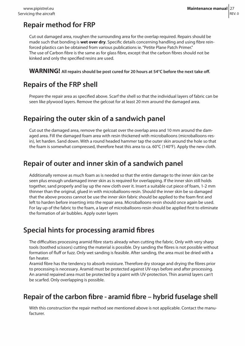
Repair method for FRPCut out damaged area, roughen the surrounding area for the overlap required. Repairs should be made such that bonding is wet over dry. Specific details concerning handling and using fibre rein-forced plastics can be obtained from various publications ie. “Petite Plane Patch Primer.”The use of Carbon fibre is the same as for glass fibre, except that the carbon fibres should not be kinked and only the specified resins are used.
WARNING! All repairs should be post cured for 20 hours at 54°C before the next take off.
Repairs of the FRP shellPrepare the repair area as specified above. Scarf the shell so that the individual layers of fabric can be seen like plywood layers. Remove the gelcoat for at least 20 mm around the damaged area.
Repairing the outer skin of a sandwich panelCut out the damaged area, remove the gelcoat over the overlap area and 10 mm around the dam-aged area. Fill the damaged foam area with resin thickened with microballoons (microballoons-res-in), let harden. Sand down. With a round headed hammer tap the outer skin around the hole so that the foam is somewhat compressed, therefore heat this area to ca. 60°C (140°F). Apply the new cloth.
Repair of outer and inner skin of a sandwich panelAdditionally remove as much foam as is needed so that the entire damage to the inner skin can be seen plus enough undamaged inner skin as is required for overlapping. If the inner skin still holds together, sand properly and lay up the new cloth over it. Insert a suitable cut piece of foam, 1-2 mm thinner than the original, glued in with microballoons-resin. Should the inner skin be so damaged that the above process cannot be use the inner skin fabric should be applied to the foam first and left to harden before inserting into the repair area. Microballoons-resin should once again be used.For lay up of the fabric to the foam, a layer of microballoons-resin should be applied first to eliminate the formation of air bubbles. Apply outer layers
Special hints for processing aramid fibresThe difficulties processing aramid fibre starts already when cutting the fabric. Only with very sharp tools (toothed scissors) cutting the material is possible. Dry sanding the fibres is not possible without formation of fluff or fuzz. Only wet sanding is feasible. After sanding, the area must be dried with a fan heater.Aramid fibre has the tendency to absorb moisture. Therefore dry storage and drying the fibres prior to processing is necessary. Aramid must be protected against UV-rays before and after processing.An aramid repaired area must be protected by a paint with UV-protection. Thin aramid layers can’t be scarfed. Only overlapping is possible.
Repair of the carbon fibre - aramid fibre – hybrid fuselage shellWith this construction the repair method see mentioned above is not applicable. Contact the manu-facturer.
Servicing the aircraft

28 Maintenance manual www.pipistrel.euREV. 0
Repairing small dents in a sandwich panel skin (no cracks in the gelcoat)
Small dents can usually be removed by heating up to 60° to 70° C (140° -158°F). Use a hot air blower to heat the area of the dent. Extreme caution must be used or the heat will damage the skin and melt the foam core. The crushed foam will then spring back to its original form, so that thedent will hardly be seen. Final sanding with wet sandpaper grade 600 should finish the job. In more severe cases, one coat of gelcoat will remove all trace of the dent.
Outer skin finishRepairs should be such that the area is exactly level or only slightly higher than the surrounding skin surfaces. Sand the hardened repair surface with dry grade 80 sandpaper. Fill with Polyester filler, let harden and sand with dry sandpaper. When the surface is smooth, sand the repair area and at least 5 cm (2 in.) of the surrounding gelcoat with wet sandpaper grade 400. Spray the repair area with 5 coats of gelcoat. After the gelcoat has hardened, sand with grade 400, 600 and 800 wet sandpaper until the surface is smooth. Polish with a power buffer (electric drill or similar with cloth polishing wheel). Apply a block of wax onto the rotating polishing wheel and then polish the repaired area. Do not polish in only one direction, and do not polish one spot for too long to prevent material overheating.
WARNING! After repairing control surfaces, the mass balance weights MUST be checked again with the values given in the maintenance manual. Should the maximum values be exceed-ed, then the parts have to be replaced.
Servicing the aircraft

29www.pipistrel.eu Maintenance manualREV. 0
Example of flaperon FRP repair
WARNING! Do not, under any circumstances attempt to repair damages greater than 50 mm / 2 inch in size (on wing) and/or 0.75 inch in size on any control circumstances. These require a treatment by a FRP professional!
Laminate plan for flaperon
WARNING! if the damage area is located on the flap hinge (the fabric used there is carbon fibre - black color) you must laminate using one ply of GG160 fabric, oriented diagonally to the flight direction. Also, you must apply Peel Ply on top of GG160.
Phase ICarefully cut and remove the damaged foam (Herex 3 mm) in width of at least 20 mm / 0.75 inch around the damaged area.Clean the area, paying special attention that the inner fabric is immaculate. This is of vital importance. After you have cleaned and rinsed everything, laminate the 20 mm area according to the laminate-plan shown on the drawing below.
Servicing the aircraft

30 Maintenance manual www.pipistrel.euREV. 0 Servicing the aircraft
Phase IIRemove the Peel Ply and adapt a new piece of foam (Herex 3 mm) as accurately as you possibly can and glue it with microballoons.
WARNING! Do not apply too much pressure anywhere!
Phase IIIGrind the foam if its level is too high. Also grind the external laminate around the cut-out for about 25 mm / 1 inch in a conical-shape (see next drawing). When done, laminate as follows:- Place one (1) piece of GG160 diagonally and- One (1) piece of 90070 perpendicular to the flight direction.
Phase IVSand only the outer edge of the new fabric. When done, the new surface is ready to be painted.

31www.pipistrel.eu Maintenance manualREV. 0
Drawing of skin final repair
Servicing the aircraft

32 Maintenance manual www.pipistrel.euREV. 0 Servicing the aircraft
Example of wing FRP repair
WARNING! Do not, under any circumstances attempt to repair damages greater than 50 mm / 2 inch in size (on wing) and/or 20 mm / 0.75 inch in size on any control circumstances. These re-quire a treatment by a FRP professional!
Phase IPreparing the surface. Carefully clean the damaged foam and check if there is also a damage on the inner fabric.
If the inner fabric in not damaged fill the hole with microballoons as you can see on the drawing be-low. In case the hole is through the inner fabric as well, you have to repair the inner fabric, too. The new patch must be at least 20 mm / 0.75 inch bigger than the damaged area. You also have to replace (glue) the missing foam with a new one.
Gap filling drawing

33www.pipistrel.eu Maintenance manualREV. 0
Phase IILaminating. Sand to a taper the outer fabric in a shape of a cone at least 25 mm around the dam-aged area (see drawing below) and laminate only the ground surface with fabrics as follows:- Two (2) pieces of 92110 and- One (1) piece of 90070
When laminating be careful about the orientation of the fibres. The fibres of 92110 must be put di-agonally to the flight direction, the fibres of 90070 must be put perpendicular to this direction. The directions are also shown in the drawing below.
Phase III Sanding. You can sand only the surface (ring) around the damaged area. This surface is shown inprevious drawing. When done the surface is ready for painting.
Servicing the aircraft

34 Maintenance manual www.pipistrel.euREV. 0 Servicing the aircraft
Weight and BalancePlease see the ALPHA Electro POH for information regarding weighing procedures and CG determi-nation.
35www.pipistrel.eu Maintenance manualREV. 0
This page is intentionally left blank.
36 Maintenance manual www.pipistrel.euREV. 0
Control levers
Wings
Tail surfaces
Brakes
Electrical system
Energy storage/powerplant
Schematics
37Se
rvic
e m
anua
lSc
hem
atic
s
Mul
ti-pu
rpos
e gr
ease
Loct
ite 2
43Lo
ctite
648
ABB
REVI
ATIO
NS
INSP
ECTI
ON
PER
IOD
SSY
MBO
LS
glue
grea
se
oil
hand
insp
.
UVM
243
648
ww
w.p
ipis
trel
.eu
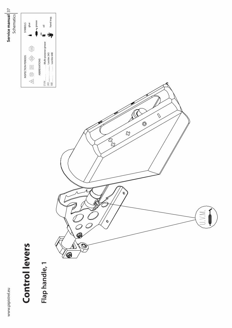
Cont
rol l
ever
s
Flap
han
dle,
1

38Se
rvic
e m
anua
lSc
hem
atic
s
Mul
ti-pu
rpos
e gr
ease
Loct
ite 2
43Lo
ctite
648
ABB
REVI
ATIO
NS
INSP
ECTI
ON
PER
IOD
SSY
MBO
LS
glue
grea
se
oil
hand
insp
.
UVM
243
648
pipi
stre
l.eu
Flap
han
dle,
2

39Se
rvic
e m
anua
lSc
hem
atic
s
Mul
ti-pu
rpos
e gr
ease
Loct
ite 2
43Lo
ctite
648
ABB
REVI
ATIO
NS
INSP
ECTI
ON
PER
IOD
SSY
MBO
LS
glue
grea
se
oil
hand
insp
.
UVM
243
648
ww
w.p
ipis
trel
.eu
Cont
rol s
tick

40Se
rvic
e m
anua
lSc
hem
atic
s
Mul
ti-pu
rpos
e gr
ease
Loct
ite 2
43Lo
ctite
648
ABB
REVI
ATIO
NS
INSP
ECTI
ON
PER
IOD
SSY
MBO
LS
glue
grea
se
oil
hand
insp
.
UVM
243
648
pipi
stre
l.eu
Rudd
er p
edal
s
Chan
ge fl
uid
ever
y 10
00
fligh
t hou
rs o
r 5 y
ears

41Se
rvic
e m
anua
lSc
hem
atic
s
Mul
ti-pu
rpos
e gr
ease
Loct
ite 2
43Lo
ctite
648
ABB
REVI
ATIO
NS
INSP
ECTI
ON
PER
IOD
SSY
MBO
LS
glue
grea
se
oil
hand
insp
.
UVM
243
648
ww
w.p
ipis
trel
.eu
Flap
leve
rs

42Se
rvic
e m
anua
lSc
hem
atic
s
Mul
ti-pu
rpos
e gr
ease
Loct
ite 2
43Lo
ctite
648
ABB
REVI
ATIO
NS
INSP
ECTI
ON
PER
IOD
SSY
MBO
LS
glue
grea
se
oil
hand
insp
.
UVM
243
648
pipi
stre
l.eu
Win
gs
win
g’s
exte
rior

43Se
rvic
e m
anua
lSc
hem
atic
s
Mul
ti-pu
rpos
e gr
ease
Loct
ite 2
43Lo
ctite
648
ABB
REVI
ATIO
NS
INSP
ECTI
ON
PER
IOD
SSY
MBO
LS
glue
grea
se
oil
hand
insp
.
UVM
243
648
ww
w.p
ipis
trel
.eu
win
g’s
inte
rior

44Se
rvic
e m
anua
lSc
hem
atic
s
Mul
ti-pu
rpos
e gr
ease
Loct
ite 2
43Lo
ctite
648
ABB
REVI
ATIO
NS
INSP
ECTI
ON
PER
IOD
SSY
MBO
LS
glue
grea
se
oil
hand
insp
.
UVM
243
648
pipi
stre
l.eu
Tail
surf
aces
hori
zont
al ta
il su
rfac
es

45Se
rvic
e m
anua
lSc
hem
atic
s
Mul
ti-pu
rpos
e gr
ease
Loct
ite 2
43Lo
ctite
648
ABB
REVI
ATIO
NS
INSP
ECTI
ON
PER
IOD
SSY
MBO
LS
glue
grea
se
oil
hand
insp
.
UVM
243
648
ww
w.p
ipis
trel
.eu
vert
ical
tail
surf
aces

46Se
rvic
e m
anua
lSc
hem
atic
s
Mul
ti-pu
rpos
e gr
ease
Loct
ite 2
43Lo
ctite
648
ABB
REVI
ATIO
NS
INSP
ECTI
ON
PER
IOD
SSY
MBO
LS
glue
grea
se
oil
hand
insp
.
UVM
243
648
pipi
stre
l.eu
Brak
es
hydr
aulic
bra
kes’
driv
e
47Se
rvic
e m
anua
lSc
hem
atic
sw
ww
.pip
istr
el.e
u
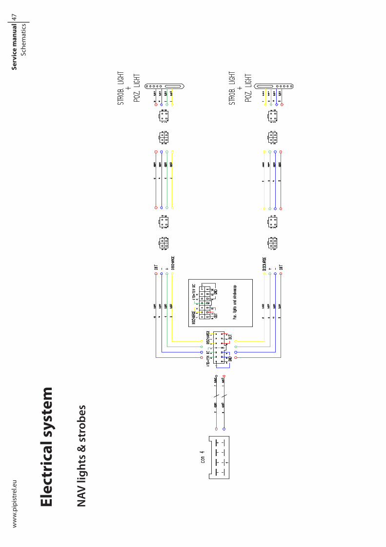
Elec
tric
al s
yste
m
NAV
ligh
ts &
str
obes

48Se
rvic
e m
anua
lSc
hem
atic
sw
ww
.pip
istr
el.e
u
Ener
gy s
tora
ge/p
ower
plan
t

49www.pipistrel.eu Maintenance manualREV. 0
This page is intentionally left blank.

50 Maintenance manual www.pipistrel.euREV. 0
Elevator vertical pushrod replacement
Fixed Pitch Propeller
Flaperon Hinge Replacement
Flaperon Lateral Drive Assembly
Flaperon Mass Balance Weights Installation
Hydraulic Fluid Lines Assembly
Bleeding the Hydraulic Brake Lines
Wheel Brake Repair
Nose Wheel Strut Assembly
Repairs

51Se
rvic
e m
anua
lRe
pairs
ww
w.p
ipis
trel
.eu
Elev
ator
Ver
tical
Pus
hrod
Rep
lace
men
t

52Se
rvic
e m
anua
lRe
pairs
ww
w.p
ipis
trel
.eu
Fixe
d Pi
tch
Prop
elle
r Ass
embl
y

53Se
rvic
e m
anua
lRe
pairs
ww
w.p
ipis
trel
.eu
Flap
eron
Hin
ge R
einf
orce
men
t

54Se
rvic
e m
anua
lRe
pairs
ww
w.p
ipis
trel
.eu
Flap
eron
Lat
eral
Dri
ve A
ssem
bly

55Se
rvic
e m
anua
lRe
pairs
ww
w.p
ipis
trel
.eu
Flap
eron
Mas
s Ba
lanc
e W
eigh
ts In
stal
latio
n

56Se
rvic
e m
anua
lRe
pairs
ww
w.p
ipis
trel
.eu Hydraulic Fluid Lines Assembly

57Se
rvic
e m
anua
lRe
pairs
ww
w.p
ipis
trel
.eu
Blee
ding
the
Hyd
raul
ic B
rake
Lin
es
58Se
rvic
e m
anua
lRe
pairs
ww
w.p
ipis
trel
.eu
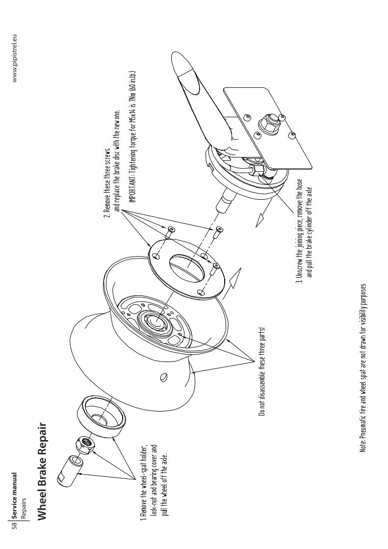
Whe
el B
rake
Rep
air

59www.pipistrel.eu Maintenance manualREV. 0
This page is intentionally left blank.

60 Maintenance manual www.pipistrel.euREV. 0
System warnings and errors
9 AppendixAppendix

61www.pipistrel.eu Maintenance manualREV. 0
System warnings and errorsAIRCRAFT
Warnings Pilot action
BATTERY 1/2 OVERTEMPERATURE
- Reduce power- Monitor battery temperature- Abort mission if necessary
BATTERY SOC < 10%- Throttle idle
- Abort mission (battery will disconnect by itself, de-pends on the cell voltage)
Errors Pilot action
ONLY ONE BATTERY PACK IS ACTIVEThis error appears when inverter is ON and when motor RPM exceeds 300.
- Do not take-off
BATTERY 1/2 DISCONNECTED DUE TO [OVERCURRENT WHILE CHARGING,
OVERTEMPERATURE, CONNECTOR DIS-CONNECT, CELL UNVERVOLTAGE, CELL
OVERVOLTAGE]
Errors OVERTEMPERATURE, OVERCURRENT WHILE CHARGING and CELL UNDERVOLTAGE only appear while flying.
- Reduce power immediately (battery will disconnect by itself)
BATTERY 1/2 STARTUP FAILED CODE: X
This error appears after turning the power enable switch on du-ring ground operation. »X« represents the error number.
- Do not take-off- Note the number - Report error number to technical support at
DRIVE OVERTEMPERATURE
This error appears when maximum inverter or motor temperature is exceeded.
- Reduce power- Monitor temperature- If the temperature doesn`t drop abort mission
DRIVE TEMPERATURE SENSOR FAILURE
WARNING!!! The inverter may reduce power to 0 if and when sensor failure happens.
- Reduce power- Abort mission
DRIVE COMMUNICATION FAILUREThe error only appears during ground operation.
- Abort mission ( in this case the start-up is not possible)
COOLANT SENSOR FAILURE- Reduce power - Abort mission
DC/DC COMMUNICATION FAILURE - Abort mission
DC/DC MALFUNCTION - Abort mission
DC/DC NOT WORKINGThis error appears when motor RPM exceeds 300.
- Abort mission
POWER LEVER COMMUNICATION FAILURE
When this error appears the power setting will stay on the last value.
- Look for somewhere to land- As soon as the landing spot is within the glide cone, pull out the PWR CTRL circuit breaker and land
DRIVE AUX POWER FAILUREWhen this error appears, the motor and inverter don`t have power. This error only appears during ground operation.
- Abort mission
PUMP AUX POWER FAILURE
This error indicates water pump failure and only appears during ground operation.
- Abort mission
Appendix

62 Maintenance manual www.pipistrel.euREV. 0
CHARGERErrors Pilot action
CONNECTOR UNLOCK FAILURE- Abort charging- Contact technical support at [email protected]
BALS UNLOCK FAILUREWhen this error appears, the cable between the charger and the power source not plugged in properly.
- Disconnect and re-connect the charging cable
POWER STAGE BOOT FAILURE - Contact technical support at [email protected]
POWER STAGE INPUT VOLTAGE FAILURE- Abort charging- Contact technical support at [email protected]
TC NOT PRESENTThis error appears when the TC charging module isn‘t working.
- Contact technical support at [email protected]
RELAY TURN ON FAILURE - Contact technical support at [email protected]
RELAY TURN OFF FAILURE FAILURE - Contact technical support at [email protected]
BATTERY VOLTAGE DETECTION FAILURE - Contact technical support at [email protected]
COMMUNICATION FAILURE- Abort charging- Contact technical support at [email protected]
EA LOCK FAILUREWhen this error appears, the cable between the aircraft and the charger is not plugged in properly.
- Disconnect and re-connect the charging cable
BATTERY ACTIVATION FAILURE- Abort charging- Contact technical support at [email protected]
CHARGING RELAY FAILURE- Abort charging- Contact technical support at [email protected]
UNSUPPORTED BATTERY TYPE- Abort charging- Contact technical support at [email protected]
Appendix

63www.pipistrel.eu Maintenance manualREV. 0
Request for Change to AircraftRequest for Letter of Authorisation
Please log into the owner’s area of Pipistrel’s website (www.pipistrel.si) to find out more about how to request/attain a LOA.

Pipistrel LSA s.r.l.
Via Aquileia 7534170 Gorizia
Italy, EU
www.pipistrel-usa.comwww.pipistrel.eu