major mount - tyler camera systems, camera mounts€¦ · · 2015-04-22tyler – major mount ......
TRANSCRIPT
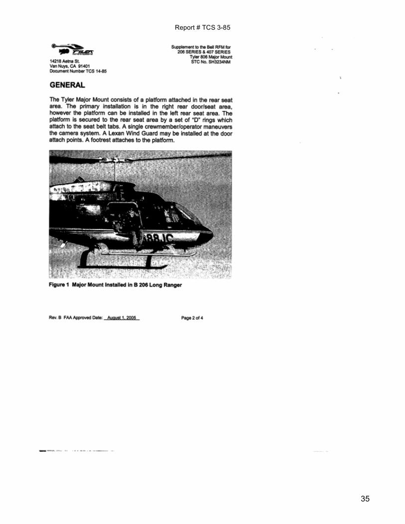
Tyler – Major Mount For Bell 407 & 206/206L Series Helicopters
FAA STC # SH3234NM EASA __________
This manual is available for download from our web site.
Tyler Camera Systems 14218 Aetna Street Van Nuys, California 91401 • USA www.tylermount.com • 800-390-6070 • (818) 989-4420 • Fax (818) 989-0423
Major MountMajor Mount 407 & Jet Ranger / Long Ranger
Installation Manual
PLEASE RETURN THIS MANUAL WITH EQUIPMENT
Report # TCS 3-85
2
LOG OF PAGES
REV
PAGE NO.
PAGE DATE
DESCRIPTION
FAA APPROVED
NC Jul 1, 85 Initial Issue
A ALL Mar 29, 01 Updated Report
B
3, 11, 12 Nov 11, 04 Added backrest picture – revised wording
C ALL Sep 15, 08 Added 407 model
D ALL Oct 3, 08 Added Approved Camera Section and Appendix A
MODEL: Major Mount JOB #: __407____
REPORT #: TCS 3-85 DATE: 8-1-85
MAJOR MOUNT (MODEL 806)
INSTALLATION MANUAL FOR
407 & 206/206L HELICOPTERS
PREPARED BY: N. Tyler 5-27-90 CHECKED BY: _____________ APPROVED BY: _____________
# OF PAGES: ________________ # OF DRAWINGS: ___0____________
Report # TCS 3-85
3
TABLE OF CONTENTS
Section 1 List of Approved Cameras & Acceptance Process Pg 4-5 Section 2 Assembly Instructions Pg 6-24 Section 3 Weight and Balance Pg 25-26

Report # TCS 3-85
4
SECTION 1 List of Approved Cameras & Acceptance Process The Tyler 407 & 206/206L Major Mount was certified with the Arri III film camera and lens and a self-contained power supply. The following cameras have been installed and flown on the mount at different times and using ships power. • ARRI® / Arriflex® cameras • Panavision® cameras • Imax® cameras (in particular, models: MSN and IW5) • Aaton® • Éclair® • Sony® cameras • Panasonic® • Ikegami® cameras • Hitachi® cameras • Canon® cameras • RED® camera This STC addresses the Structural, Performance & Handling Qualities requirement for the largest configuration flown. Smaller or lighter cameras/sensors are approved without further flight testing. The specific sensor/cameras/light not listed here is accepted with this follow-on test plan found in Appendix A. For helicopters registered in the U.S. or other countries recognizing FAA certification: Once the testing is completed by the Integrator/Operator and the flight test conducted by the Pilot/Operator and the FAA (certified) mechanic the sensor /camera / light payload can be added to the accepted list in this manual. The report contained herein must be completed and signed prior to the “return to service” for any sensor/ camera / light payload. The flight will be conducted as an “Operational Check Flight”. Operational check flights do not require a special airworthiness certificate in the experimental category. The term “operational check flight” (14 CFR § 91.407(b)) includes flight tests performed to check installation and/or operation of an approved STC, amended TC, or any other FAA-approved data after installation and return to service. Operational check flights are performed under the current airworthiness certificate. The purpose of this test is to ensure the approved modification and/or alteration functions properly and does not adversely affect aircraft operation. For helicopters registered in an EU-member state: The specific sensor/camera/light to be added to the STC has to be introduced by a Minor Change with an EASA accepted certification program. Once the testing is completed by the Integrator/Operator and the flight test conducted by the Pilot/Operator and EASA Engineer and the Minor Change is approved the sensor/camera/light, can

Report # TCS 3-85
5
be added to the accepted list in this manual. The report contained herein must be completed and signed prior to the “return to service” for sensor/camera/light. The flights have to be conducted with a “Permit to Fly”. The purpose of this test is to ensure the approved modification and/or alteration functions properly and does not adversely affect aircraft operation. For all helicopters: The installation is assumed to have a self-contained power supply or connected to the aircraft through a previously approved electrical connection. If modification to the ship’s system is necessary to support this installation, additional minor modifications with appropriate approval is necessary. Installation by persons other than a certified mechanic/engineer can be authorized if properly trained. Any mount system may be installed or removed by a Tyler Camera Systems trained technician, pilot or mechanic, and must be recorded in accordance with FAR 43.9. The training would be in accordance with EASA/JAR 145 or by an appropriate maintenance organization in accordance with applicable national requirements. The mount is designed to be installed with a minimum amount of alteration to the basic aircraft and a limited number of tools.

Report # TCS 3-85
6
SECTION 2 Assembly Instructions
The Major Mount can be installed on either side of the helicopter. Remove PI-pins or screws from doors and remove doors. Replace PI-pins or screws. Remove all seat and back cushions or other obstacles from seat and floor area. Before Proceding... • Visually inspect all Tiedown straps for chaffing or wear. • Visually check Tiedown bar for deformity or burrs. • Visually check Major Mount for signs of damage.

Report # TCS 3-85
7
Lift Camera Platform into helicopter around the center support column, placing the foot risers (on the bottom of the Camera Platform) into the foot wells. The Camera Platform should fit snug against the support column and the rear foot well area.

Report # TCS 3-85
8
Place the helicopter seat belt through the two "D" Rings on the Camera Platform. Buckle the (existing) center seat belt together leaving it loose. A Belly Strap is provided (already attached) to one side of the Camera Platform. Make sure that the bottom antennas are out of the way. Place the belly strap around the bottom of the helicopter and connect it to the attach point (“D” Ring Strap) underneath the Camera Platform cushion on the other side. Slack in the Belly Strap should be pulled snug around the bottom of the helicopter.

Report # TCS 3-85
9
Install the Lord Mount unit. Line up the Lord Mount unit with the retaining bolt at the approximate center of the slot with the rubber Lord Mount boot to the Camera Operator’s right. The slot should line up with the nose and tail direction of the helicopter. Tighten the retaining bolt with the allen wrench found on the Velcro patch on top of the Camera Platform.

Report # TCS 3-85
10
Slip the Tie-down Bar through the (Right Hand) camera mount Restraint Strap, then through the existing helicopter seat belt "D" Ring. Continue by sliding the Tie-Down Bar through the camera operator’s seat belt safety strap and then through the second existing helicopter seat belt "D" Ring, and then through the center camera mount Restraint Strap. Continue sliding the Tie-down Bar through the third and fourth existing helicopter seat belt "D" Rings, and then through the (Left Hand) camera mount Restraint Strap. Secure with a bolt and nut through the end of the Tie-down Bar.
Report # TCS 3-85
11
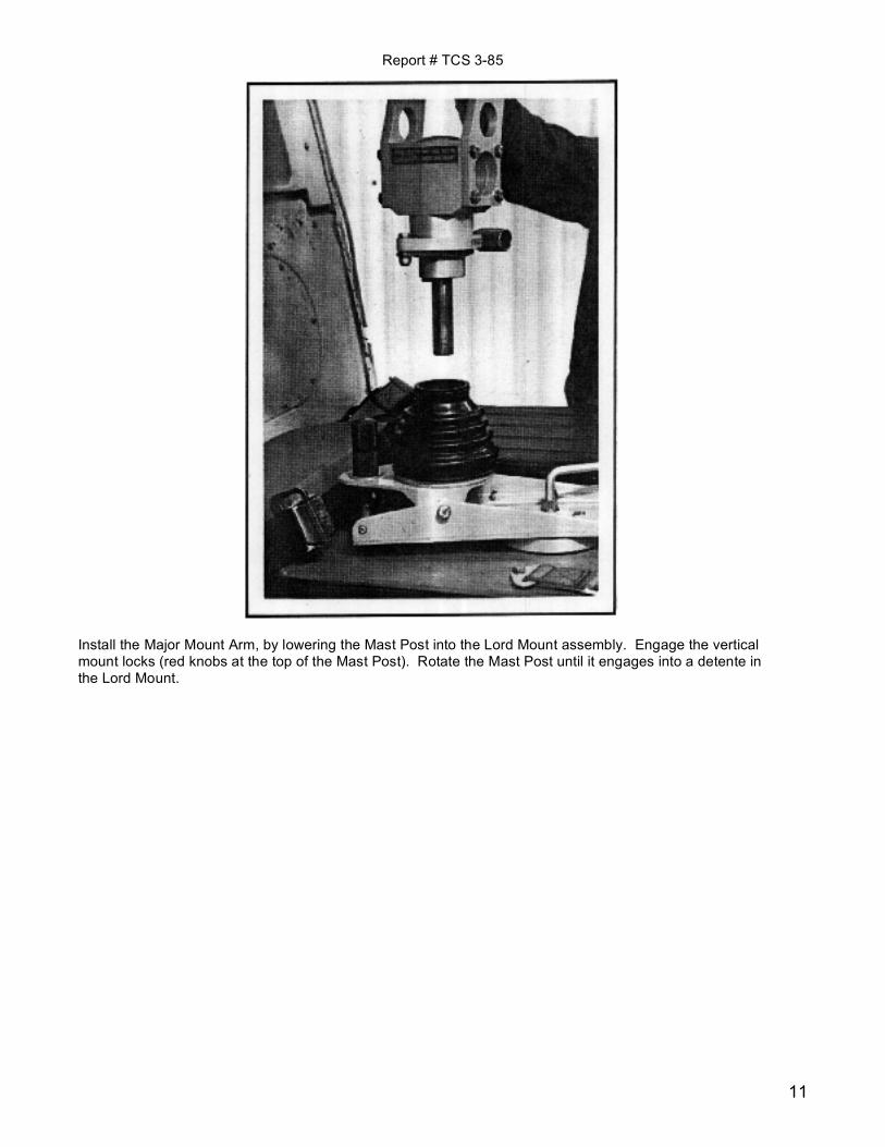
Install the Major Mount Arm, by lowering the Mast Post into the Lord Mount assembly. Engage the vertical mount locks (red knobs at the top of the Mast Post). Rotate the Mast Post until it engages into a detente in the Lord Mount.
Report # TCS 3-85
12
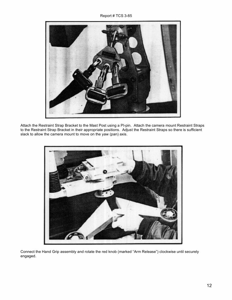
Attach the Restraint Strap Bracket to the Mast Post using a PI-pin. Attach the camera mount Restraint Straps to the Restraint Strap Bracket in their appropriate positions. Adjust the Restraint Straps so there is sufficient slack to allow the camera mount to move on the yaw (pan) axis.
Connect the Hand Grip assembly and rotate the red knob (marked “Arm Release”) clockwise until securely engaged.
Report # TCS 3-85
13
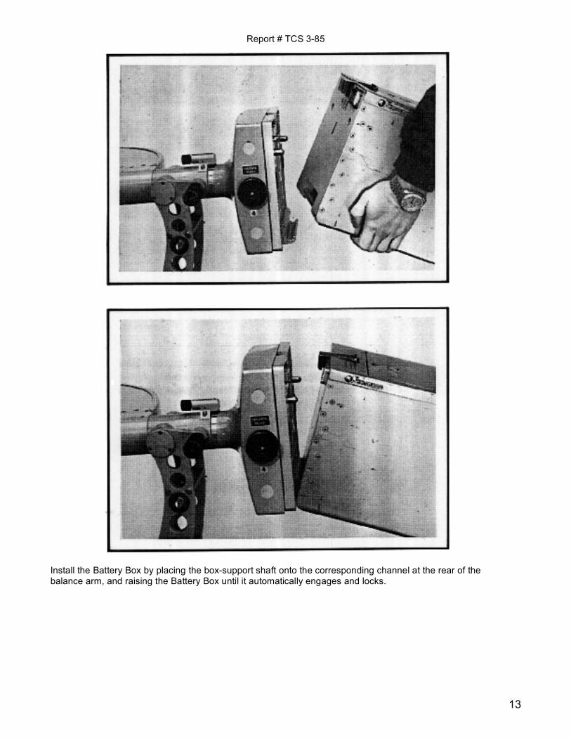
Install the Battery Box by placing the box-support shaft onto the corresponding channel at the rear of the balance arm, and raising the Battery Box until it automatically engages and locks.

Report # TCS 3-85
14
Install the camera by sliding the dovetail of the Quick Release onto the camera support assembly. While depressing the "Camera Release" Lever, slide the camera in until the lock portion of the Lever has cleared the edge of the camera support assembly and let go of it while continuing to slide the camera in until the lock portion of the Lever snaps into the camera support assembly. The "Camera Release" Lever will be flush or level with the Quick Release Plate.
Connect wiring from camera to camera mount assembly.
Report # TCS 3-85
15
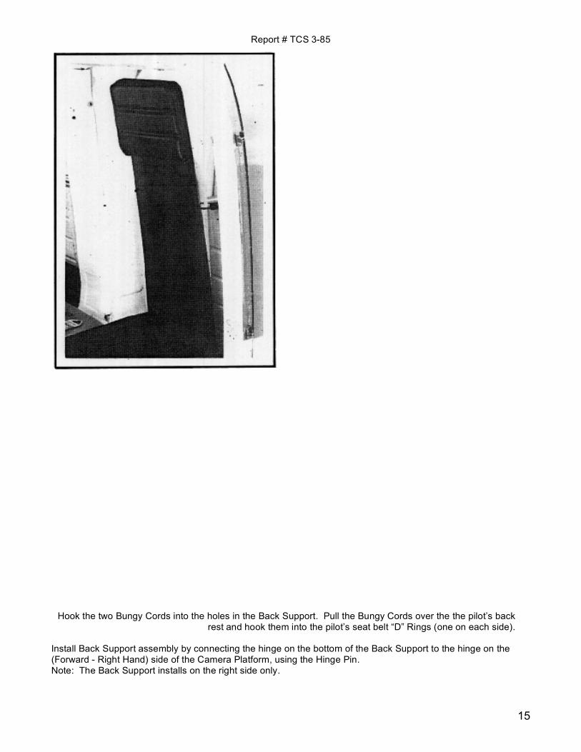
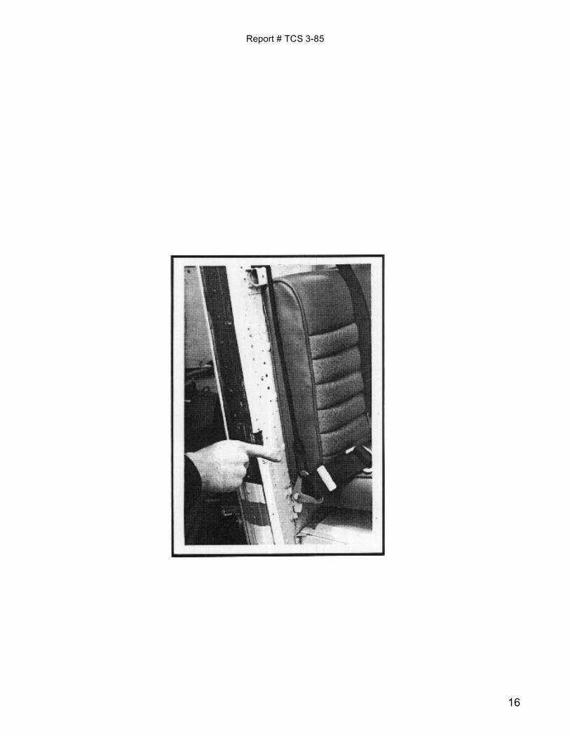
Hook the two Bungy Cords into the holes in the Back Support. Pull the Bungy Cords over the the pilot’s back rest and hook them into the pilot’s seat belt “D” Rings (one on each side).
Install Back Support assembly by connecting the hinge on the bottom of the Back Support to the hinge on the (Forward - Right Hand) side of the Camera Platform, using the Hinge Pin. Note: The Back Support installs on the right side only.
Report # TCS 3-85
16

Report # TCS 3-85
17
Install the Lexan Wind-Screen to the existing door hinges. Secure with PI-pins or the bolts and nuts that normally hold the door in place. Install on the Right or Left side, depending on the direction the Camera Platform Arm is installation. This completes the installation for Right side filming. Reinstall the Left-Rear helicopter door.

Report # TCS 3-85
18
Appendix A

Report # TCS 3-85
19
1 Overview
This Appendix provides the requirements necessary to qualify additional sensor / camera / light payloads not listed in the front of this manual. It may also be used as a check list for previously approved sensor /cameras / light payloads if desired. The STC flight testing was conducted and the STC approved with the largest and heaviest payload expected for use with this mount. The specific sensor/cameras/light not listed in the installation manual of equal or lesser than the limit case are accepted with this follow-on test plan. For helicopters registered in the U.S. or other countries recognizing FAA certification: Once the testing is completed by the Integrator/Operator and the flight test conducted by the Pilot/Operator and the FAA (certified) mechanic the sensor/camera/light payload can be added to the accepted list in this manual. The report contained herein must be completed and signed prior to the “return to service” for any sensor/camera/light payload. The flight will be conducted as an “Operational Check Flight”. Operational check flights do not require a special airworthiness certificate in the experimental category. The term “operational check flight” (14 CFR § 91.407(b)) includes flight tests performed to check installation and/or operation of an approved STC, amended TC, or any other FAA-approved data after installation and return to service. Operational check flights are performed under the current airworthiness certificate. The purpose of this test is to ensure the approved modification and/or alteration functions properly and does not adversely affect aircraft operation. For helicopters registered in an EU-member state: The specific sensor/camera/light to be added to the STC has to be introduced by a Minor Change with an EASA accepted certification program. Once the testing is completed by the Integrator/Operator and the flight test conducted by the Pilot/Operator and EASA Engineer and the Minor Change is approved the sensor/camera/light, can be added to the accepted list in this manual. The report contained herein must be completed and signed prior to the “return to service” for sensor/camera/light. The flights have to be conducted with a “Permit to Fly”. The purpose of this test is to ensure the approved modification and/or alteration functions properly and does not adversely affect aircraft operation. For all helicopters: The installation is assumed to have a self-contained power supply or connected to the aircraft through a previously approved electrical connection. If modification to the ship’s system is necessary to support this installation, additional minor modifications with appropriate approval is necessary. All systems are to be operational and an image viewable by one of the crew displayed in the cockpit/cabin. The pilot is not expected to make this evaluation and should direct his/her attention to flying the aircraft. Pictures of the installation and location of the power and controller as used in the test will provide additional documentation for the record.
Report # TCS 3-85
20
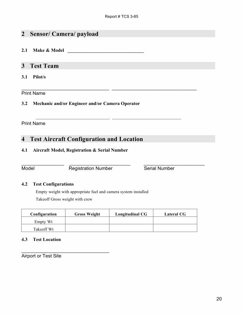
2 Sensor/ Camera/ payload
2.1 Make & Model ________________________________
3 Test Team
3.1 Pilot/s _________________________________ ________________________________ Print Name
3.2 Mechanic and/or Engineer and/or Camera Operator _______________________________ _____________________________
Print Name
4 Test Aircraft Configuration and Location
4.1 Aircraft Model, Registration & Serial Number
________________ _______________________ _______________________ Model Registration Number Serial Number
4.2 Test Configurations Empty weight with appropriate fuel and camera system installed
Takeoff Gross weight with crew
Configuration Gross Weight Longitudinal CG Lateral CG
Empty Wt
Takeoff Wt
4.3 Test Location _________________________________ Airport or Test Site
Report # TCS 3-85
21
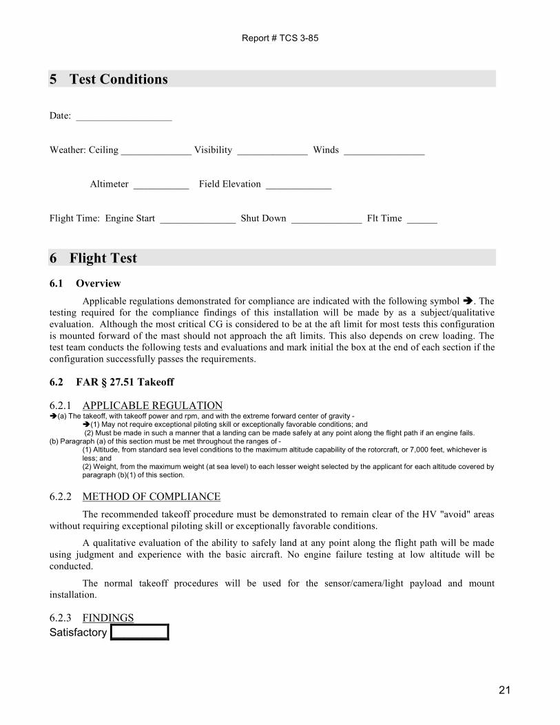
5 Test Conditions
Date: ___________________
Weather: Ceiling ______________ Visibility ______________ Winds ________________
Altimeter ___________ Field Elevation _____________
Flight Time: Engine Start _______________ Shut Down ______________ Flt Time ______
6 Flight Test
6.1 Overview Applicable regulations demonstrated for compliance are indicated with the following symbol . The
testing required for the compliance findings of this installation will be made by as a subject/qualitative evaluation. Although the most critical CG is considered to be at the aft limit for most tests this configuration is mounted forward of the mast should not approach the aft limits. This also depends on crew loading. The test team conducts the following tests and evaluations and mark initial the box at the end of each section if the configuration successfully passes the requirements.
6.2 FAR § 27.51 Takeoff
6.2.1 APPLICABLE REGULATION (a) The takeoff, with takeoff power and rpm, and with the extreme forward center of gravity -
(1) May not require exceptional piloting skill or exceptionally favorable conditions; and (2) Must be made in such a manner that a landing can be made safely at any point along the flight path if an engine fails.
(b) Paragraph (a) of this section must be met throughout the ranges of - (1) Altitude, from standard sea level conditions to the maximum altitude capability of the rotorcraft, or 7,000 feet, whichever is less; and (2) Weight, from the maximum weight (at sea level) to each lesser weight selected by the applicant for each altitude covered by paragraph (b)(1) of this section.
6.2.2 METHOD OF COMPLIANCE The recommended takeoff procedure must be demonstrated to remain clear of the HV "avoid" areas
without requiring exceptional piloting skill or exceptionally favorable conditions.
A qualitative evaluation of the ability to safely land at any point along the flight path will be made using judgment and experience with the basic aircraft. No engine failure testing at low altitude will be conducted.
The normal takeoff procedures will be used for the sensor/camera/light payload and mount installation.
6.2.3 FINDINGS Satisfactory _________
Report # TCS 3-85
22
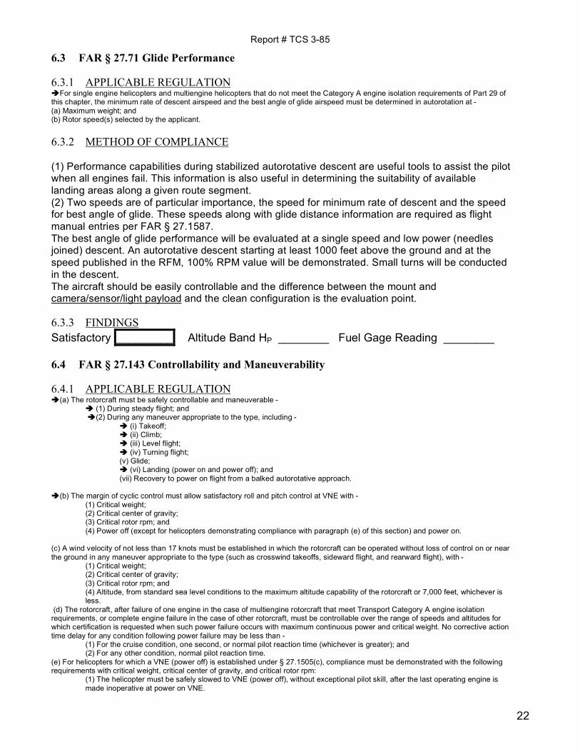
6.3 FAR § 27.71 Glide Performance
6.3.1 APPLICABLE REGULATION For single engine helicopters and multiengine helicopters that do not meet the Category A engine isolation requirements of Part 29 of this chapter, the minimum rate of descent airspeed and the best angle of glide airspeed must be determined in autorotation at - (a) Maximum weight; and (b) Rotor speed(s) selected by the applicant.
6.3.2 METHOD OF COMPLIANCE (1) Performance capabilities during stabilized autorotative descent are useful tools to assist the pilot when all engines fail. This information is also useful in determining the suitability of available landing areas along a given route segment. (2) Two speeds are of particular importance, the speed for minimum rate of descent and the speed for best angle of glide. These speeds along with glide distance information are required as flight manual entries per FAR § 27.1587. The best angle of glide performance will be evaluated at a single speed and low power (needles joined) descent. An autorotative descent starting at least 1000 feet above the ground and at the speed published in the RFM, 100% RPM value will be demonstrated. Small turns will be conducted in the descent. The aircraft should be easily controllable and the difference between the mount and camera/sensor/light payload and the clean configuration is the evaluation point.
6.3.3 FINDINGS Satisfactory _________ Altitude Band HP ________ Fuel Gage Reading ________
6.4 FAR § 27.143 Controllability and Maneuverability
6.4.1 APPLICABLE REGULATION (a) The rotorcraft must be safely controllable and maneuverable -
(1) During steady flight; and (2) During any maneuver appropriate to the type, including -
(i) Takeoff; (ii) Climb; (iii) Level flight; (iv) Turning flight; (v) Glide; (vi) Landing (power on and power off); and (vii) Recovery to power on flight from a balked autorotative approach.
(b) The margin of cyclic control must allow satisfactory roll and pitch control at VNE with -
(1) Critical weight; (2) Critical center of gravity; (3) Critical rotor rpm; and (4) Power off (except for helicopters demonstrating compliance with paragraph (e) of this section) and power on.
(c) A wind velocity of not less than 17 knots must be established in which the rotorcraft can be operated without loss of control on or near the ground in any maneuver appropriate to the type (such as crosswind takeoffs, sideward flight, and rearward flight), with -
(1) Critical weight; (2) Critical center of gravity; (3) Critical rotor rpm; and (4) Altitude, from standard sea level conditions to the maximum altitude capability of the rotorcraft or 7,000 feet, whichever is less.
(d) The rotorcraft, after failure of one engine in the case of multiengine rotorcraft that meet Transport Category A engine isolation requirements, or complete engine failure in the case of other rotorcraft, must be controllable over the range of speeds and altitudes for which certification is requested when such power failure occurs with maximum continuous power and critical weight. No corrective action time delay for any condition following power failure may be less than -
(1) For the cruise condition, one second, or normal pilot reaction time (whichever is greater); and (2) For any other condition, normal pilot reaction time.
(e) For helicopters for which a VNE (power off) is established under § 27.1505(c), compliance must be demonstrated with the following requirements with critical weight, critical center of gravity, and critical rotor rpm:
(1) The helicopter must be safely slowed to VNE (power off), without exceptional pilot skill, after the last operating engine is made inoperative at power on VNE.

Report # TCS 3-85
23
(2) At a speed of 1.1 VNE (power off), the margin of cyclic control must allow satisfactory roll and pitch control with power off.
6.4.2 METHOD OF COMPLIANCE The general requirements for control and for maneuverability are summarized in section (a), which is
largely self-explanatory.
Section (b) specifies flight at VNE with critical weight, center of gravity (CG), rotor RPM, and power. Adequate cyclic authority must remain at VNE for nose down pitching of the rotorcraft and for adequate roll control.
The helicopter will be flown between 1000 and 3000 feet above ground. The test altitude will be dependent on traffic and terrain and conditions close to sea level pressure are desirable. VNE will be the value stated in the RFM for the test density altitude . Qualitative measurement techniques (pilot opinion) will be used. The tests will include:
6.4.2.1 Takeoff
6.4.2.2 Climbing flight
6.4.2.3 Forward flight to VNE at MCP (maybe less than MCP)
6.4.2.4 Left & right 30 degree bank turns at VNE and at MCP (maybe less than MCP)
6.4.2.5 Take-off & Landings (Power on only). The aircraft should be easily controllable and adequate cyclic margins should exist throughout the flight test points. The difference between the mount and sensor / camera / light payload and the clean configuration is the evaluation point.
6.4.3 FINDINGS Satisfactory _________ Cruise Altitude HP ________ Fuel Gage Reading _______
6.5 FAR § 27.171 Stability: General
6.5.1 APPLICABLE REGULATION The rotorcraft must be able to be flown, without undue pilot fatigue or strain, in any normal maneuver for a period of time as long as that expected in normal operation. At least three landings and takeoffs must be made during this demonstration.
6.5.2 METHOD OF COMPLIANCE Compliance with the requirements of this section can often be obtained for the VFR condition without any specific or designated flight testing. This test should be conducted with minimum required systems in the aircraft and with minimum flight crew.
Compliance with this requirement will be evaluated throughout the test program.
6.5.3 FINDINGS Satisfactory _________
6.6 FAR § 27.251 Vibration
6.6.1 APPLICABLE REGULATION Each part of the rotorcraft must be free from excessive vibration under each appropriate speed and power condition.

Report # TCS 3-85
24
6.6.2 METHOD OF COMPLIANCE This flight requirement may be both a qualitative and quantitative flight evaluation. Section 27.571(a) contains the flight load survey requirement that results in accumulation of vibration quantitative data. Section 27.629 generally requires quantitative data to show freedom from flutter for each part of the rotorcraft including control or stabilizing surfaces and rotors. The aircraft should have a good track & balance for this evaluation. The airspeed should evaluated at 20 kt increments out to the RFM VNE speed. Variations in rotor RPM expected in normal flight should be evaluated. Changes in vibration are best sensed in the cyclic and pedal controls. The stability of the camera/sensor image will be a good indicator. The pilot will make a subjective evaluation. The difference between the mount and sensor / camera/ light payload and the clean configuration is the evaluation point.
6.6.3 FINDINGS Satisfactory _________
6.7 FAR § 27.773 Pilot Compartment View
6.7.1 APPLICABLE REGULATION (a) Each pilot compartment must be free from glare and reflections that could interfere with the pilot's view, and designed so that-- (1) Each pilot's view is sufficiently extensive, clear, and undistorted for safe operation; and (2) Each pilot is protected from the elements so that moderate rain conditions do not unduly impair his view of the flight path in normal flight and while landing. (b) If certification for night operation is requested, compliance with paragraph (a) of this section must be shown in night flight tests.
6.7.2 METHOD OF COMPLIANCE The section outlines requirements for pilot view in fairly general terms. The aircraft was approved with the installed glare shield and instrument panel that meet the rules. Any additional equipment/monitors must be positioned so as not to limit or obstruct the pilot’s field of view. There will be some cases where the installation will be temporary and for a unique mission and consideration should be given for these limited cases and time. If night operations are expected with an operational system, a “dark cockpit” or night evaluation will be necessary to insure the glare/reflection will not interfere with the pilot duties. A limitation to the use at night is an option. Satisfactory _________
6.8 FAR § 27.787 Cargo & Baggage Compartment
6.8.1 APPLICABLE REGULATION
Cargo and baggage compartments.
(a) Each cargo and baggage compartment must be designed for its placarded maximum weight of contents and for the critical load distributions at the appropriate maximum load factors corresponding to the specified flight and ground load conditions, except the emergency landing conditions of Sec. 27.561.
(b) There must be means to prevent the contents of any compartment from becoming a hazard by shifting under the loads specified in paragraph (a) of this section.
[(c) Under the emergency landing conditions of Sec. 27.561, cargo and baggage compartments must--
Report # TCS 3-85
25
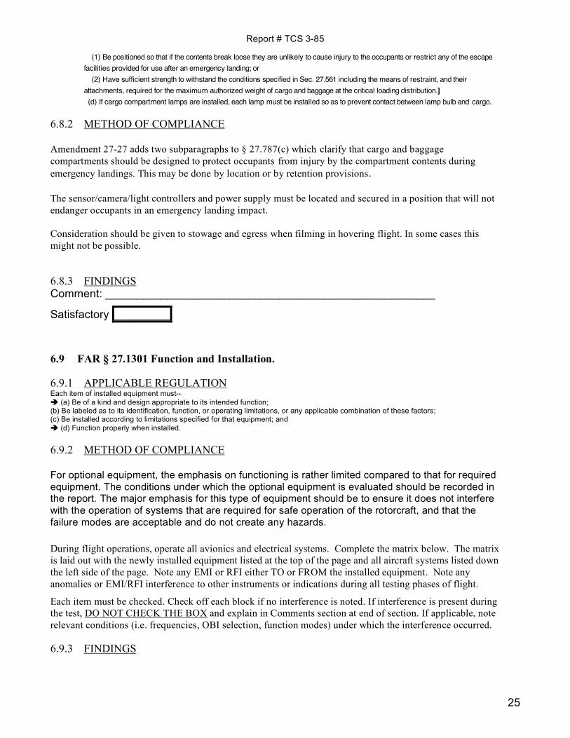
(1) Be positioned so that if the contents break loose they are unlikely to cause injury to the occupants or restrict any of the escape facilities provided for use after an emergency landing; or (2) Have sufficient strength to withstand the conditions specified in Sec. 27.561 including the means of restraint, and their attachments, required for the maximum authorized weight of cargo and baggage at the critical loading distribution.] (d) If cargo compartment lamps are installed, each lamp must be installed so as to prevent contact between lamp bulb and cargo.
6.8.2 METHOD OF COMPLIANCE Amendment 27-27 adds two subparagraphs to § 27.787(c) which clarify that cargo and baggage compartments should be designed to protect occupants from injury by the compartment contents during emergency landings. This may be done by location or by retention provisions. The sensor/camera/light controllers and power supply must be located and secured in a position that will not endanger occupants in an emergency landing impact. Consideration should be given to stowage and egress when filming in hovering flight. In some cases this might not be possible.
6.8.3 FINDINGS Comment: _____________________________________________________
Satisfactory _________
6.9 FAR § 27.1301 Function and Installation.
6.9.1 APPLICABLE REGULATION Each item of installed equipment must-- (a) Be of a kind and design appropriate to its intended function; (b) Be labeled as to its identification, function, or operating limitations, or any applicable combination of these factors; (c) Be installed according to limitations specified for that equipment; and (d) Function properly when installed.
6.9.2 METHOD OF COMPLIANCE
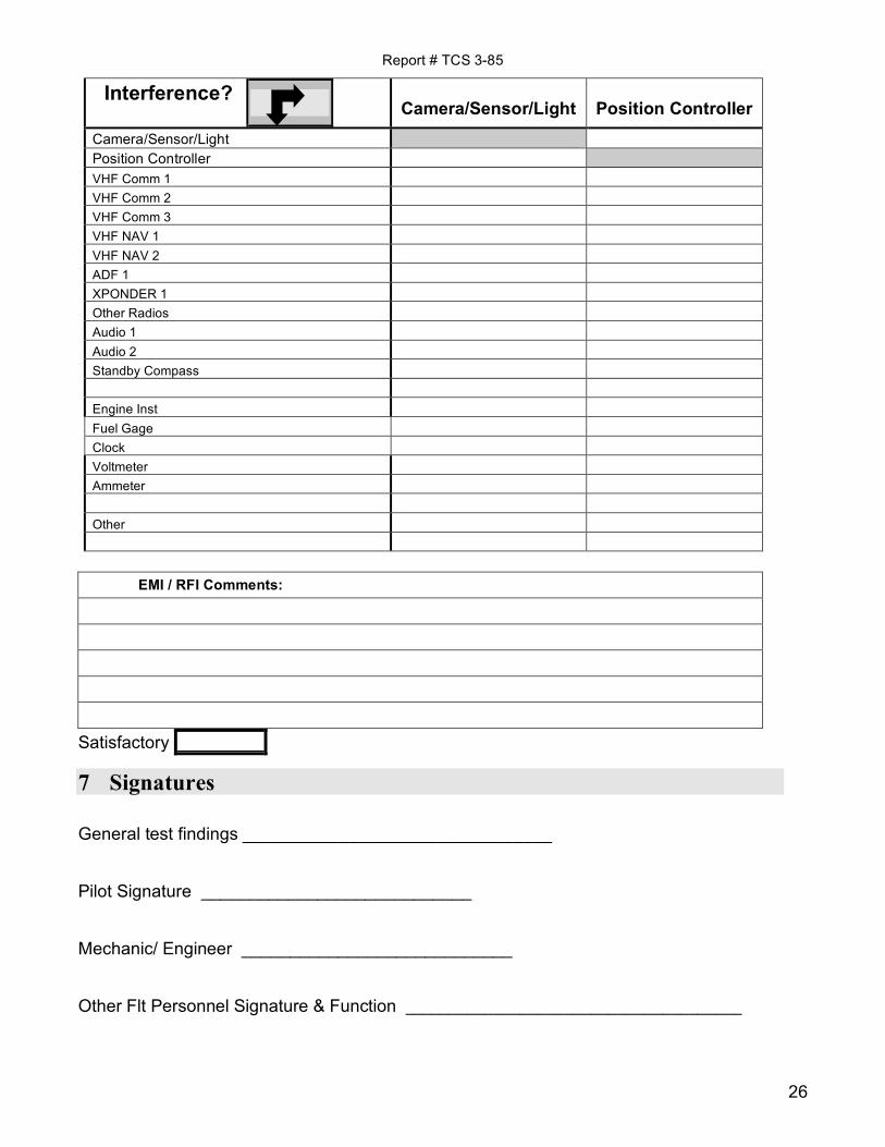
For optional equipment, the emphasis on functioning is rather limited compared to that for required equipment. The conditions under which the optional equipment is evaluated should be recorded in the report. The major emphasis for this type of equipment should be to ensure it does not interfere with the operation of systems that are required for safe operation of the rotorcraft, and that the failure modes are acceptable and do not create any hazards. During flight operations, operate all avionics and electrical systems. Complete the matrix below. The matrix is laid out with the newly installed equipment listed at the top of the page and all aircraft systems listed down the left side of the page. Note any EMI or RFI either TO or FROM the installed equipment. Note any anomalies or EMI/RFI interference to other instruments or indications during all testing phases of flight.
Each item must be checked. Check off each block if no interference is noted. If interference is present during the test, DO NOT CHECK THE BOX and explain in Comments section at end of section. If applicable, note relevant conditions (i.e. frequencies, OBI selection, function modes) under which the interference occurred.
6.9.3 FINDINGS
Report # TCS 3-85
26
Interference?
Camera/Sensor/Light Position Controller Camera/Sensor/Light Position Controller VHF Comm 1 VHF Comm 2 VHF Comm 3 VHF NAV 1
VHF NAV 2 ADF 1 XPONDER 1 Other Radios Audio 1
Audio 2 Standby Compass Engine Inst
Fuel Gage Clock Voltmeter Ammeter
Other
EMI / RFI Comments:
Satisfactory _________
7 Signatures General test findings ________________________________ Pilot Signature ____________________________ Mechanic/ Engineer ____________________________ Other Flt Personnel Signature & Function ______________________________________
Report # TCS 3-85
27
8 References 1. 14 Code of Federal Regulations, Aeronautics and Space, Chapter I – Federal Aviation
Administration, Department of Transportation, Subchapter C – Aircraft, Part 27 (Revised as of 1 January 2000.)
2. Federal Aviation Administration, Advisory Circular, AC 27-1B Certification of Normal Category Rotorcraft (ASW-110, September 9, 1999)

Report # TCS 3-85
28

Report # TCS 3-85
29

Report # TCS 3-85
30
Report # TCS 3-85
31

Report # TCS 3-85
32

Report # TCS 3-85
33
Report # TCS 3-85
34
Report # TCS 3-85
35
Report # TCS 3-85
36
Report # TCS 3-85
37
Report # TCS 3-85
38
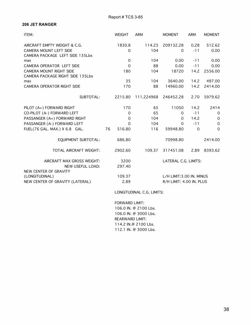
206 JET RANGER ITEM: WEIGHT ARM MOMENT ARM MOMENT
AIRCRAFT EMPTY WEIGHT & C.G. 1830.8 114.23 209132.28 0.28 512.62 CAMERA MOUNT LEFT SIDE 0 104 0 -11 0.00 CAMERA PACKAGE LEFT SIDE 135Lbs max 0 104 0.00 -11 0.00 CAMERA OPERATOR LEFT SIDE 0 88 0.00 -11 0.00 CAMERA MOUNT RIGHT SIDE 180 104 18720 14.2 2556.00 CAMERA PACKAGE RIGHT SIDE 135Lbs max 35 104 3640.00 14.2 497.00 CAMERA OPERATOR RIGHT SIDE 170 88 14960.00 14.2 2414.00
SUBTOTAL: 2215.80 111.224968 246452.28 2.70 5979.62 PILOT (A+) FORWARD RIGHT 170 65 11050 14.2 2414 CO-PILOT (A-) FORWARD LEFT 0 65 0 -11 0 PASSANGER (A+) FORWARD RIGHT 0 104 0 14.2 0 PASSANGER (A-) FORWARD LEFT 0 104 0 -11 0 FUEL(76 GAL. MAX.) X 6.8 GAL. 76 516.80 116 59948.80 0 0
EQUIPMENT SUBTOTAL: 686.80 70998.80 2414.00
TOTAL AIRCRAFT WEIGHT: 2902.60 109.37 317451.08 2.89 8393.62
AIRCRAFT MAX GROSS WEIGHT: 3200 LATERAL C.G. LIMITS: NEW USEFUL LOAD: 297.40
NEW CENTER OF GRAVITY (LONGITUDINAL) 109.37 L/H LIMIT:3.00 IN. MINUS NEW CENTER OF GRAVITY (LATERAL) 2.89 R/H LIMIT: 4.00 IN. PLUS LONGITUDINAL C.G. LIMITS: FORWARD LIMIT: 106.0 IN. @ 2100 Lbs. 106.0 IN. @ 3000 Lbs. REARWARD LIMIT: 114.2 IN.@ 2100 Lbs. 112.1 IN. @ 3000 Lbs.
Report # TCS 3-85
39
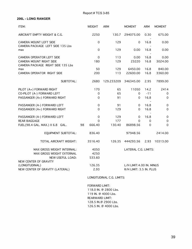
206L - LONG RANGER ITEM: WEIGHT ARM MOMENT ARM MOMENT
AIRCRAFT EMPTY WEIGHT & C.G. 2250 130.7 294075.00 0.30 675.00
CAMERA MOUNT LEFT SIDE 0 129 0 -
16.8 0.00 CAMERA PACKAGE LEFT SIDE 135 Lbs max 0 129 0.00
-16.8 0.00
CAMERA OPERATOR LEFT SIDE 0 113 0.00 -
16.8 0.00 CAMERA MOUNT RIGHT SIDE 180 129 23220 16.8 3024.00 CAMERA PACKAGE RIGHT SIDE 135 Lbs max 50 129 6450.00 16.8 840.00 CAMERA OPERATOR RIGHT SIDE 200 113 22600.00 16.8 3360.00
SUBTOTAL: 2680 129.233209 346345.00 2.95 7899.00 PILOT (A+) FORWARD RIGHT 170 65 11050 14.2 2414 CO-PILOT (A-) FORWARD LEFT 0 65 0 -11 0 PASSANGER (A+) FORWARD RIGHT 0 91 0 16.8 0
PASSANGER (A-) FORWARD LEFT 0 91 0 -
16.8 0 PASSANGER (A+) FORWARD RIGHT 0 129 0 16.8 0
PASSANGER (A-) FORWARD LEFT 0 129 0 -
16.8 0 REAR BAGGAGE 0 177 0 0 0 FUEL(98.4 GAL. MAX.) X 6.8 GAL. 98 666.40 130.40 86898.56 0 0
EQUIPMENT SUBTOTAL: 836.40 97948.56 2414.00
TOTAL AIRCRAFT WEIGHT: 3516.40 126.35 444293.56 2.93 10313.00
MAX GROSS WEIGHT INTERNAL: 4050 LATERAL C.G. LIMITS: MAX GROSS WEIGHT EXTERNAL 4250
NEW USEFUL LOAD: 533.60 NEW CENTER OF GRAVITY (LONGITUDINAL) 126.35 L/H LIMIT:4.00 IN. MINUS NEW CENTER OF GRAVITY (LATERAL) 2.93 R/H LIMIT: 3.5 IN. PLUS LONGITUDINAL C.G. LIMITS: FORWARD LIMIT: 118.0 IN. @ 2800 Lbs. 119 IN. @ 4000 Lbs. REARWARD LIMIT: 128.5 IN.@ 2900 Lbs. 126.5 IN. @ 4000 Lbs.
Report # TCS 3-85
40
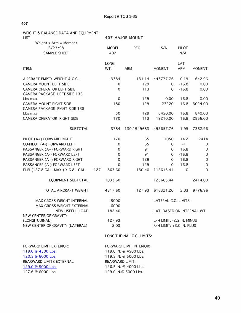
407 WEIGHT & BALANCE DATA AND EQUIPMENT LIST 407 MAJOR MOUNT
Weight x Arm = Moment 6/23/98 MODEL REG S/N PILOT
SAMPLE SHEET 407 N/A LONG LAT ITEM: WT. ARM MOMENT ARM MOMENT
AIRCRAFT EMPTY WEIGHT & C.G. 3384 131.14 443777.76 0.19 642.96 CAMERA MOUNT LEFT SIDE 0 129 0 -16.8 0.00 CAMERA OPERATOR LEFT SIDE 0 113 0 -16.8 0.00 CAMERA PACKAGE LEFT SIDE 135 Lbs max 0 129 0.00 -16.8 0.00 CAMERA MOUNT RIGHT SIDE 180 129 23220 16.8 3024.00 CAMERA PACKAGE RIGHT SIDE 135 Lbs max 50 129 6450.00 16.8 840.00 CAMERA OPERATOR RIGHT SIDE 170 113 19210.00 16.8 2856.00
SUBTOTAL: 3784 130.1949683 492657.76 1.95 7362.96 PILOT (A+) FORWARD RIGHT 170 65 11050 14.2 2414 CO-PILOT (A-) FORWARD LEFT 0 65 0 -11 0 PASSANGER (A+) FORWARD RIGHT 0 91 0 16.8 0 PASSANGER (A-) FORWARD LEFT 0 91 0 -16.8 0 PASSANGER (A+) FORWARD RIGHT 0 129 0 16.8 0 PASSANGER (A-) FORWARD LEFT 0 129 0 -16.8 0 FUEL(127.8 GAL. MAX.) X 6.8 GAL. 127 863.60 130.40 112613.44 0 0
EQUIPMENT SUBTOTAL: 1033.60 123663.44 2414.00
TOTAL AIRCRAFT WEIGHT: 4817.60 127.93 616321.20 2.03 9776.96
MAX GROSS WEIGHT INTERNAL: 5000 LATERAL C.G. LIMITS: MAX GROSS WEIGHT EXTERNAL 6000
NEW USEFUL LOAD: 182.40 LAT. BASED ON INTERNAL WT. NEW CENTER OF GRAVITY (LONGITUDINAL) 127.93 L/H LIMIT: -2.5 IN. MINUS NEW CENTER OF GRAVITY (LATERAL) 2.03 R/H LIMIT: +3.0 IN. PLUS LONGITUDINAL C.G. LIMITS: FORWARD LIMIT EXTERIOR: FORWARD LIMIT INTERIOR: 119.0 @ 4500 Lbs. 119.0 IN. @ 4500 Lbs. 120.5 @ 6000 Lbs 119.5 IN. @ 5000 Lbs. REARWARD LIMITS EXTERNAL REARWARD LIMIT: 129.0 @ 5000 Lbs. 126.5 IN. @ 4000 Lbs. 127.6 @ 6000 Lbs. 129.0 IN.@ 5000 Lbs.