make a quadcopter using kk 2.1.5 flight controller...pg 2 a quadcopter, also called a quadrotor...
TRANSCRIPT

Pg
1
Make a Quadcopter using KK 2.1.5
Flight Controller

Pg
2
A quadcopter, also called a quadrotor helicopter or quadrotor,
is a multirotor helicopter that is lifted and propelled by four rotors.
Quadcopters are classified as rotorcraft, as opposed to fixed-
wing aircraft, because their lift is generated by a set
of rotors (vertically oriented propellers).
Typical Applications

Pg
3
1000 KV Brushless Motor
A2212/13.RPM/V: 1000KV.Batteries: 2-3 Li-Poly
Efficiency: 80%.
Current: 4-10A (>75%).
No load current: 10V/0.5A.Max.
transient current: 12A/60S
Shaft diameter: 3.17mm.
Dimensions: 27.5*30mm.
Weight limit for compatible model plane: 300-900g.
Compatible propeller model: APC 10*5/ APC 11*5.5/
APC 10*4.7
KK 2.1.5 Multi rotor Flight Control Board
Size: 50.5mm x 50.5mm x 12mm
Weight: 21 gram (Inc. Piezo buzzer)
IC: Atmega644 PA
Gyro/Acc: 6050MPU
Auto-level: Yes
Input Voltage: 4.8-6.0V
AVR interface: standard 6 pin.
Signal from Receiver: 1520us (5 channels)
Signal to ESC: 1520us
Firmware Version 1.6
Specifications

Pg
4

Pg
5
KK 2.1.5 Multi rotor Flight Control Board
KK2.1 Multi-Rotor controller manages the flight of (mostly) multi-
rotor Aircraft (Tri copters, Quadcopters, Hex copters etc.). Its
purpose is to stabilize the aircraft during flight and to do this, it
takes signals from on-board gyroscopes (roll, pitch and yaw)
and passes these signals to the Atmega324PA processor, which

Pg
6
in-turn processes signals according the users selected firmware
(e.g. Quadcopter) and passes the control signals to the
installed Electronic Speed Controllers (ESCs) and the
combination of these signals instructs the ESCs to make fine
adjustments to the motors rotational speeds which in-turn
stabilizes the craft. The KK2.1 Multi-Rotor control board also
uses signals from your radio system via a receiver (Rx) and
passes these signals together with stabilization signals to the
Atmega324PA IC via the aileron; elevator; throttle and rudder
user demand inputs. Once processed, this information is sent to
the ESCs which in turn adjust the rotational speed of each motor
to control flight orientation (up, down, backwards, forwards, left,
right, yaw)
Initial Setup
STEP-1
Mount the FC on the frame
with the LCD facing front and
the buttons facing back. You
can use the supplied
antistatic foam container as
a form of protective case for
the Flight Controller on the
craft.
STEP-2
Connect the receiver outputs to the corresponding left-hand
side of the controller board. The pins are defined as:

Pg
7
RECIEVER CHANNEL FLIGHT CONTROLLER
Aileron Aileron
Elevator Elevator
Throttle Throttle
Rudder Rudder
AUX1 AUX
Ensure the negative (black or brown) is orientated so that it is on
the pin that is nearest to the edge of the Flight Controller Board,
so looking at the board the color sequence will be Black, Red and
Orange. The channels are connected as follows from the front of
the board towards the push buttons: -
Typical receiver servo connections are:
STEP-3 Connect the ESC’s to the right side of the Flight
Controller Board. M1 is towards the front of the board and M8 is
nearest to the push buttons. The negative (black or brown) lead
towards the edge of the FC. The negative (black or brown) lead is
connected to the edge of the Flight Controller.
DO NOT MOUNT THE PROPELLERS AT THIS STAGE – FOR
SAFETY REASONS
Pg
8
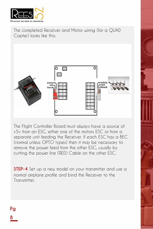
The completed Receiver and Motor wiring (for a QUAD
Copter) looks like this:
The Flight Controller Board must always have a source of
+5v from an ESC, either one of the motors ESC or from a
separate unit feeding the Receiver. If each ESC has a BEC
(normal unless OPTO types) then it may be necessary to
remove the power feed from the other ESC, usually by
cutting the power line (RED) Cable on the other ESC.
STEP-4 Set up a new model on your transmitter and use a
normal airplane profile and bind the Receiver to the
Transmitter.

Pg
9
PI Editor
Receiver Test
Mode Settings
Stick Scaling
Misc. Settings
Self-Level
Settings
Camera Stab
Settings Sensor
Test ACC
Calibration
CPPM Settings
Mixer Editor
Show Motor
Layout Load
Motor Layout
Factory Reset
STEP-5
Turn on the power and press the ‘Menu’ button,
then using the ‘Up’ and ‘Down’ buttons highlight
‘Receiver Test sub-menu and press Enter. Now move
each channel on your transmitter and check that
the displayed direction corresponds with the stick
movements on the Flight Controller, if any are
reversed, then go to your Transmitter and reverse
that channel. Check that the AUX channel is
showing "ON" when you activate the AUX Switch on
your transmitter, if not, reverse the AUX channel on
your transmitter. Use the trim or sub-trim controls on
your transmitter to adjust the channel values shown
on the LCD to zero.
STEP-6
Scroll down to and enter the "Load Motor Layout"
sub-menu and choose the configuration you want.
If the configuration you want is not listed, use the
"Mixer Editor" sub-menu to make one. See later for
more on that.
STEP-7
Enter the "Show Motor Layout" sub-menu and
confirm the following. Is the configuration correct?
Are the motors and servos connected the correct
output? Correct rotation direction? Does the motor
speed up when dropping the arm it is mounted on?
PI Editor
Receiver Test
Mode Settings
Stick Scaling
Misc. Settings
Self-Level
Settings
Camera Stab
Settings Sensor
Test ACC
Calibration
CPPM Settings
Mixer Editor
Show Motor
Layout Load
Motor Layout
Factory Reset

Pg
10
PI Editor
Receiver Test
Mode Settings
Stick Scaling
Misc. Settings
Self-Level
Settings
Camera Stab
Settings Sensor
Test ACC
Calibration
CPPM Settings
Mixer Editor
Show Motor
Layout Load
Motor Layout
Factory Reset
PI Editor
Receiver Test
Mode Settings
Stick Scaling
Misc. Settings
Self-Level
Settings
Camera Stab
Settings Sensor
Test ACC
Calibration
CPPM Settings
Mixer Editor
Show Motor
Layout Load
Motor Layout
Factory Reset
STEP-8 Enter the “Receiver test" and check for nominal
values on each channel, move your Transmitter
sticks around to ensure they are all working,
including AUX1.
Enter the "PI Editor” sub-menu and check for
correct PI gain values and use this menu option
to adjust the PI gain settings. Use the PREV and
NEXT buttons to highlight the parameter you want
to change, then press the CHANGE button. To
adjust both Roll and Pitch at the same time, see
the "Mode Settings "sub-menu.
At this stage the propellers can be fitted to test
the Flight Control board. Hold the craft (!) and
then Arm it by give right rudder and zero throttle
for a few seconds. It will beep and the RED LED
will turn on. However, do-not arm it until you have
put the multicopter on the ground and stepped
away 5 meters. After landing, place it in SAFE
Mode by holding the rudder to left with zero
throttle. It will beep and the RED LED will turn off,
always do this before you approach the
multicopter. If the craft wants to tip over right
away, check your connections and your custom
made mixer table if you have one. If it shakes and
maybe climbs after it’s airborne, adjust the Roll
and Pitch Pgain down or if it easily tips over after
its airborne, adjust up. If it drifts away, use the
trims to keep the drift down. It will normally drift
away with the wind.

Pg
11
PI Editor
Receiver Test
Mode Settings
Stick Scaling
Misc. Settings
Self-Level
Settings
Camera Stab
Settings Sensor
Test ACC
Calibration
CPPM Settings
Mixer Editor
Show Motor
Layout Load
Motor Layout
Factory Reset
Turn on the Self-levelling by holding right aileron
while arming or disarming it. Turn it off by holding
left aileron. Alternatively you can assign this to
the AUX channel. See below. Sub-menu
descriptions.
STEP-9
Enter the "Mode Settings" and check and adjust:
"Self-Level": Determines how the self-levelling
function will be controlled, either by STICK or an
AUX Channel. "STICK MODE": Self-levelling is turned
on by holding the aileron to the right when arming
or disarming. Turn it off with left aileron. "AUX": Self-
levelling is turned on/off by the AUX Channel. "Auto
Disarm": If set to YES then Flight Control board will
automatically disarm itself after 10-mins of
inactivity. "CPPM Enabled": Determine if the Flight
Control Board is to use CPPM data input. PI Editor
Receiver Test
Mode Settings
Stick Scaling
Misc. Settings
Self-Level
Settings
Camera Stab
Settings Sensor
Test ACC
Calibration
CPPM Settings
Mixer Editor
Show Motor
Layout Load
Motor Layout
Factory Reset
STEP-10
Enter the "Stick Scaling" option, where you can
adjust the response from the stick to your liking.
Higher number gives higher response and lower
numbers the converse. This is similar to the
endpoint or volume adjustment on your
transmitter, where you can adjust your transmitter
to adjust the stick response and use the stick
scaling if you want more or less response from
stick inputs

Pg
12
"Misc. Settings":
"Minimum Throttle": Adjust the setting so that the
motors just keep running when the Transmitter
throttle stick is at a minimum. "Height Dampening":
Adjust so that variations in height are minimised.
"Height D. Limit": Adjust to limit control over Height
Dampening to prevent over control.
"Alarm 1/10 volts”: Adjusts the battery alarm
voltage set-point. When set to 0 (zero) the alarm
is disabled. Adjust this value to suit the battery in
use and monitored by the Flight Control Board
sensor input. For a standard 3-cell LiPo battery of
11.1volts use a value of 3.60 volts per cell to
denote an empty battery and then set this value
(in 1/10’s) to (3.6 x 3 * 10) = 108 and when the
supply voltage drops to 10.8volts the alarm will
sound. Note, if you set this value above zero and
no battery is attached / monitored then the alarm
will sound. As the voltage being monitored nears
the set point the time between beeps will shorten,
so a long time between pulses when the alarm
voltage is getting close to very short time intervals
when the voltage is at the alarm set point. “Servo
Filter”: This setting is a Low-Pass Filter, that enables
channel jitter to be ignored, a good setting to
start off with is 50 (mS). If you experience channel
jitter then increase this value, if none then set to 0
(zero).
PI Editor
Receiver Test
Mode Settings
Stick Scaling
Misc. Settings
Self-Level
Settings
Camera Stab
Settings Sensor
Test ACC
Calibration
CPPM Settings
Mixer Editor
Show Motor
Layout Load
Motor Layout
Factory Reset

Pg
13
PI Editor
Receiver Test
Mode Settings
Stick Scaling
Misc. Settings
Self-Level
Settings
Camera Stab
Settings
Sensor Test
ACC
Calibration
CPPM Settings
Mixer Editor
Show Motor
Layout Load
Motor Layout Factory Reset
"Sensor Test": Displays the output from the
sensors. See if all shows "OK". Move the FC
around and see that the numbers change.
"ACC Calibration": Follow the instructions on
the LCD to calibrate the Acceleration Sensors,
which is only necessary to do once at initial
setup.
"CPPM Settings":
This menu allows different Transmitter
manufacturers standards for CPPM channels to
be re-assigned, thus:
Roll (Ail): 1 to 2
Pitch (Ele): 2 to 1
Throttle: 3
Yaw(Rud): 4
AUX: 5
This enables the Flight Control board to match
any supplier’s standard
PI Editor
Receiver Test
Mode Settings
Stick Scaling
Misc. Settings
Self-Level
Settings
Camera Stab
Settings Sensor
Test ACC
Calibration
CPPM Settings
Mixer Editor
Show Motor
Layout Load
Motor Layout
Factory Reset

Pg
14
PI Editor
Receiver Test
Mode Settings
Stick Scaling
Misc. Settings
Self-Level
Settings
Camera Stab
Settings Sensor
Test ACC
Calibration
CPPM Settings
Mixer Editor
Show Motor
Layout Load
Motor Layout
Factory Reset
“Mixer Editor”:
“Channel”: Select the channel to be adjusted.
"Throttle": Amount of throttle command. Usually
100% if the output channel is connected to an ESC.
"Aileron":
Amount of aileron/roll command. Use positive value
for motors on the right side of the roll axis and
negative for the left side of the roll axis. The value is
given by the motor's distance from the roll axis.
Increased values denote a further distance.
"Elevator": Amount of elevator/pitch command. Use
a positive value for motors on the front side of the
pitch axis and negative value for the back side of
the pitch axis. The value is given by the motor's
distance from the pitch axis. More is further away.
"Rudder": The amount of rudder/yaw command.
Usually 100%. Use a positive value for a CW
spinning propeller and negative for a CCW
spinning propeller.
"Offset" Item: Applies a constant offset to the
channel. Keep this zero when it is an ESC channel
and around 50% when connected to a servo or
on the AUX channel. You can fine tune the
channels position by adjusting this value. "Type:"
Item: Set it to the type (servo or ESC) connected
to the channel. For ESC: Output PWM rate is
always high. Outputs zero when disarmed or
throttle is at idle. Applies the "Minimum Throttle"
item from the "Misc. Settings" sub-menu when
armed and throttle is above zero.
For the Servo setting: Output PWM rate can be
high or low. Outputs the offset value when
disarmed or throttle is at idle.
"Rate": High rate (400Hz) for ESC or digital
servos, or low rate (80Hz) for analogue servos.
Distance from the pitch axis. More is further away. "Rudder": The
amount of rudder/yaw command. Usually 100%. Use a positive value
for a CW spinning propeller and negative for a CCW spinning
propeller.
"Offset" Item: Applies a constant offset to the channel. Keep this zero
when it is an ESC channel and around 50% when connected to a
servo or on the AUX channel. You can fine tune the channels position
by adjusting this value. "Type:" Item: Set it to the type (servo or ESC)
connected to the channel. For ESC: Output PWM rate is always high.
Outputs zero when disarmed or throttle is at idle. Applies the "Minimum
Throttle" item from the "Misc. Settings" sub-menu when armed and
throttle is above zero.
For the Servo setting: Output PWM rate can be high or low. Outputs
the offset value when disarmed or throttle is at idle.
"Rate": High rate (400Hz) for ESC or digital servos, or low rate (80Hz)
for analogue servos.

Pg
15
Tuning Guide
Gimbal Connection Guide
Enable the Camera Control by turning it on by
going to "Cam Stab Settings" screen and set
the gains to a non-zero value. Start with 500. A
negative value reverses servo direction. Adjust
value until camera is steady.
1. The Gimbal Roll servo is connected to
Motor-7 output.
2. The Gimbal Pitch servo is connected to
Motor-8 output.
Enable the Camera Control by turning it on by
going to "Cam Stab Settings" screen and set the
gains to a non-zero value. Start with 500. A
negative value reverses servo direction. Adjust
value until camera is steady.
1. The Gimbal Roll servo is connected to Motor-
7 output.
2. The Gimbal Pitch servo is connected to
Motor-8 output.
PI Editor
Receiver Test
Mode Settings
Stick Scaling
Misc. Settings
Self-Level
Settings Camera
Stab Settings
Sensor Test
ACC
Calibration
CPPM Settings
Mixer Editor
Show Motor
Layout Load
Motor Layout Factory Reset
PI Editor
Receiver Test
Mode Settings
Stick Scaling
Misc. Settings
Self-Level
Settings Camera
Stab Settings
Sensor Test
ACC
Calibration
CPPM Settings
Mixer Editor
Show Motor
Layout Load
Motor Layout
Factory Reset

Pg
16
Accessing the Self- Levelling Mode
1. You can access the self-levelling mode either from the
settings of STICK or AUX channel.
Connection Diagram:
3. Use the offset values to trim servo position, but keep the
values close to 50% by adjusting servo linkage first.
4. The camera stabilization starts as soon as you move the
Throttle any stick
5. If you put the Throttle at Idle/Minimum the camera
stabilization will be switched-OFF. NOTE: If you are using an
“OPTO” ESC you may need an external 5v power source from
an SBEC.

Pg
17
2. When set to AUX Mode you must connect a spare channel
usually CH5 or Ch6 and changing the Transmitter switch
position will enable/disable Self-Levelling mode.
3. When set to STICK Mode to go into Self-Levelling Mode,
you must set the Throttle to Minimum and set maximum Left
Rudder
Whilst at the same time, setting maximum Left Aileron to disable
SL or maximum Right Aileron to enable SL.
Flight Controller Sounds
Status Screen
Displays the message "SAFE" and the KK2 will not arm unless it says
"OK".
General Points
Error messages can only be reset by cycling the power, except for
the "sensors not calibrated" message, which is reset after a
successful sensor calibration.
Error messages include lost RX connection.
1. One Beep (short beep, 2 sec delay) is emitted when the board
is armed and the throttle is closed, this is for safety reasons so you
know it’s armed.
2. One Long Beep is emitted when the board is either Armed or
Disarmed.

Pg
18
The KK2.1 has an auto-disarm function and will disarm itself after
20 sec if throttle is at idle. For extra safety. Can be turned on/off
in "Mode Settings" menu.
Lost Model Alarm
The KK2.1 has a lost aircraft alarm and starts to beep (1 sec on
and 4 sec off) after 30min of no activity (arm/disarm).
Model Types Supported
Dualcopter
Tricopter
Y6 Quadcopter +
Quadcopter X
Hexcopter +
Hexcopter X
Octocopter +
Octocopter X
X8 +
X8 X
H8
H6
V8
V6
Aero 1S Aileron
Aero 2S Aileron
Flying Wing
Singlecopter 2M 2S
Singlecopter 1M 4S

Pg
19
1) Quadcopter Frame (Preferably one which has a built in Power
Distribution board) - 1
2) Microcontroller (KK 2.15 Flight Controller) - 1
3) Electronic Speed Control (30 Amps) (4 pieces)
4) Brushless Motor (1000KV) (4 pieces)
5) Propellers (2 sets)
Hardware required
Pg
20
6) Power Distribution Board (Not needed if frame has a built in
one)
7) Lithium-Polymer 3000 mAH Battery -1
8) Fly Sky FS-T6 Controller includes the Receiver - 1
1) Basic soldering skills
2) Alan keys
3) Shrink tubes
4) Zip ties (To hold the ESC's onto the frame)
5) Glue gun (To put all over the connections to avoid any
contact between them)
1) The motors and ESC's can be connected to each other via
direct soldering or using Bullet Connectors of 4mm dimension.
2) The ESC's are then connected to the power distribution board,
or in this case directly to the frame which has an inbuilt power
distribution board, by soldering.
(Make sure to know if the ESC's are supposed to be flashed or not,
mine did not required to do so.)
3) Once this is done, solder the battery wire to the frame.
4) Once all the soldering work is done, and the hardware is setup,
connect the KK Board (again flashed with the latest firmware) with
the ESC servo wires, and Receiver.
Tools and Knowledge
Assemble and Connect

Pg
21

Pg
22
If your code is all correct and your connections are all good
you should see the LCD screen on the board lit up, from where
you can easily calibrate both the Accelerometer and
Magnetometer.
Plug in the battery and Test Your Quadcopter

Pg
23

Pg
24