making a wood joint out of 8pieces for a structural...
TRANSCRIPT

MAKING A WOOD JOINT OUT OF 8PIECES FOR A
STRUCTURAL SYSTEM
Wise 2016 | Digital Design Unit


MAKING A WOOD JOINT OUT OF 8 PIECES FOR A STRUCTURAL SYSTEM
FELIX DANNECKER
RESEARCH PROJECTWINTER TERM 2016/17
DIGITAL DESIGN UNITPROF. OLIVER TESSMANN
BASTIAN WIBRANEK

DDU | Felix Dannecker 4
Basis for this research project was a studio work at the Digital Design Unit from Prof. Oliver Tessmann that aimed to design a FabLab. The outcome of my project was a con-cept of a space that would build itself. The idea was that the building structure would represent within its own building process the whole belief of the FabLab movement started by Neil Gershenfeld. In theory the participants of the FabLab build and create their own building elements in house and create new spaces for their Labs. As time moves on the participants reconfigure and adjust their elements behalf on the experience gathered from assembling their new spaces. In order to create such a process Modular building strategies seem to be the most suitable solution for this.
In the field of Architecture and Design, Modulation is an ad-ditive process of a repeating element creating a bigger form or structure. During research for the design project I came across a PhD thesis from Kenneth Cheung called: ”Digital Cellular Solids: reconfigurable composite materials.”In his Dissertation he “seeks to demonstrate the applicabi-lity of a digital material approach in designing new cellular materials and methods for assembly of structures with static reconfigurability.” He developed a structural modular sys-
ABSTRACT
DDU | Felix Dannecker5
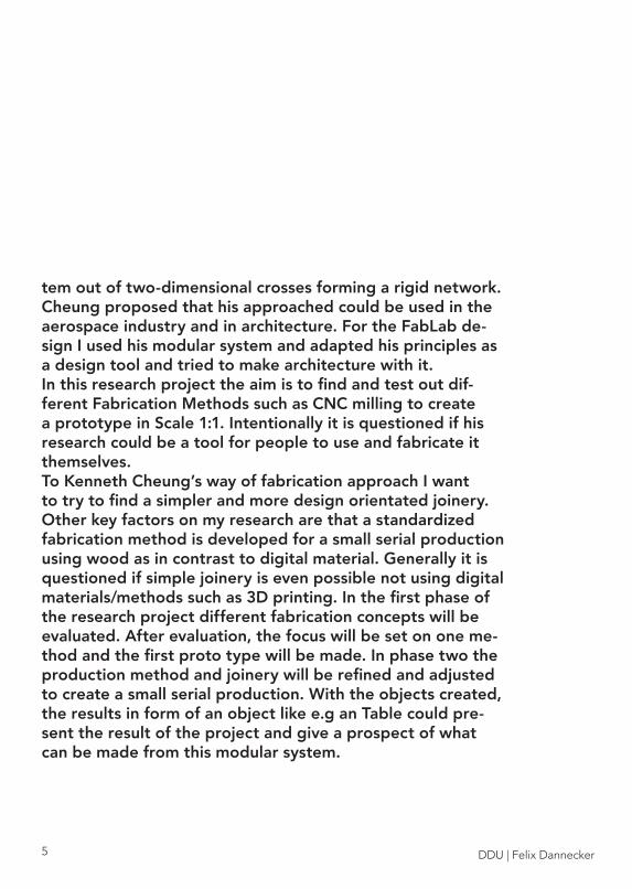
tem out of two-dimensional crosses forming a rigid network. Cheung proposed that his approached could be used in the aerospace industry and in architecture. For the FabLab de-sign I used his modular system and adapted his principles as a design tool and tried to make architecture with it. In this research project the aim is to find and test out dif-ferent Fabrication Methods such as CNC milling to create a prototype in Scale 1:1. Intentionally it is questioned if his research could be a tool for people to use and fabricate it themselves.To Kenneth Cheung’s way of fabrication approach I want to try to find a simpler and more design orientated joinery. Other key factors on my research are that a standardized fabrication method is developed for a small serial production using wood as in contrast to digital material. Generally it is questioned if simple joinery is even possible not using digital materials/methods such as 3D printing. In the first phase of the research project different fabrication concepts will be evaluated. After evaluation, the focus will be set on one me-thod and the first proto type will be made. In phase two the production method and joinery will be refined and adjusted to create a small serial production. With the objects created, the results in form of an object like e.g an Table could pre-sent the result of the project and give a prospect of what can be made from this modular system.

DDU | Felix Dannecker 6
BACKGROUND

DDU | Felix Dannecker7
Digital cellular solids: reconfigurable composite materials.
In the design project I was inspired by Kenneth Cheung PhD thesis and adapted his modular system. His way of joining the modules together was simplified for a concep-tual model in scale 1:20. In his thesis, Cheung proposes that his modulation could also be used for architecural design. For this research project I used the same structu-ral system to manufacture a mock up in Scale 1:1. Howe-ver this construction will not be made from digital mate-rials. The aim is to manufacture this structural system in wood with a simple joinery. Kenneth Cheung is referen-ced in this work to show where the idea has its origin.
KENNETH CHEUNG

DDU | Felix Dannecker 8
JAPANESE JOINERY
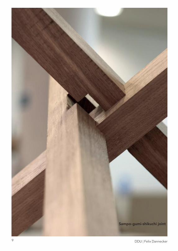
Japanese carpentry has a long tradition and has crea-ted wood joints and combinations that express a unique simplicity and purity. The art of japanese carpentry was a example to create a wood joint that uses similar techniques to create a wood joint were 8 pieces could be linked together. The sampo-gumi-shikuchi joint as seen on the right page was the fi rst reference to create a similar wood joint. After researching for similar joint I did not came across a traditional wood connection out of 8 pieces. There are also many japanese joints that work with pins connecting two pieces together. Example for this is the Miyajima-tsugi connection. These two princip-les are the foundation to try to create a wood joint that is able to hold 8 pieces together.
Miyajima-tsugi joint
DDU | Felix Dannecker9
Sampo-gumi-shikuchi joint

DDU | Felix Dannecker 10
RESEARCH

DDU | Felix Dannecker11
C-LAB - Hfg Offenbach
MASSIVEHOLZVERBINDUNGEN
This was a project by the Hochschule für Gestaltung Offenbach that looked at japanese joinery and tried to CNC mill these joints. The C-Lab argues that with CNC milling these carpentry skills would become accesible to a broader spectrum of people since no craftsman skills are required.

DDU | Felix Dannecker 12
COMPLEX TIMBER STRUCUTRES
Gramazio Kohler - ETH Zürich
The research project from Gramazio Kohler analysed how „soft wood“ which is often not considered for constructi-on can be assembled through automation with robots to create lightweight structures that are robust and com-plex.

DDU | Felix Dannecker13
DDU | Felix Dannecker 14
3D PRINTED JOINTS
Ollé Gellért

DDU | Felix Dannecker15
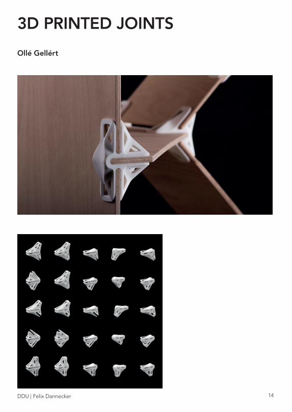
Ollé Gellért invented a system of 3D printed joints that when stacked together make a shelf. Through a broad range of different joint geometries different shelf forms can be created. This project shows how digital material is used already to create simple and cheap furniture.
DDU | Felix Dannecker 16
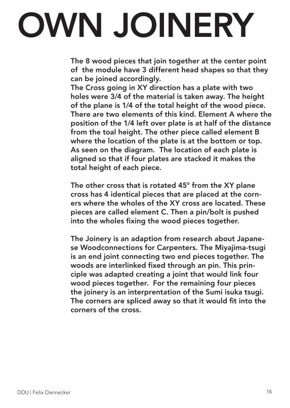
The 8 wood pieces that join together at the center point of the module have 3 different head shapes so that they can be joined accordingly. The Cross going in XY direction has a plate with two holes were 3/4 of the material is taken away. The height of the plane is 1/4 of the total height of the wood piece. There are two elements of this kind. Element A where the position of the 1/4 left over plate is at half of the distance from the toal height. The other piece called element B where the location of the plate is at the bottom or top. As seen on the diagram. The location of each plate is aligned so that if four plates are stacked it makes the total height of each piece.
The other cross that is rotated 45° from the XY plane cross has 4 identical pieces that are placed at the corn-ers where the wholes of the XY cross are located. These pieces are called element C. Then a pin/bolt is pushed into the wholes fixing the wood pieces together.
The Joinery is an adaption from research about Japane-se Woodconnections for Carpenters. The Miyajima-tsugi is an end joint connecting two end pieces together. The woods are interlinked fixed through an pin. This prin-ciple was adapted creating a joint that would link four wood pieces together. For the remaining four pieces the joinery is an interprentation of the Sumi isuka tsugi. The corners are spliced away so that it would fit into the corners of the cross.
OWN JOINERY

DDU | Felix Dannecker17
A
B
C

DDU | Felix Dannecker 18

DDU | Felix Dannecker19
From the joinery of the pages be-fore these structural systems can be assembled. This system can be orientated in different direction to create a different pattern.

DDU | Felix Dannecker 20
With RhinoCAM it is possible to simulate the milling paths of an 3D computer model. Tools, Materials can be selected to fi nd a effi cient milling path for the machine. CNC milling is a very effi cient way to manufacture many elements without the need of many craftsman. Simulating the path for the machine was the easiest part. To actual operate the machine a trained craftsman is needed. Without the knowledge about how to use these machines it soon turned out that this was a diffi cult procedure to create many elements in a fast time. Additionally it turned out that element C could not be manu-factured with an 3 axis milling machine due to its geometry. After many conversations with professional carpenters they convinced me that CNC milling might not be the right pro-cess to manufacure the geometry for my wood construction.As element A and B are much faster to cut with a saw as to adjust it with a machine.
CNC MILLING

DDU | Felix Dannecker21

DDU | Felix Dannecker 22
BY HAND
After CNC milling was not the optimal way to manufacture this wood joint. I went one step back and just simply tried to make it by hand to get a feeling about the geometry for element C because this was the most challenging part of the wood joint. With a japanese carpenters saw it worked howe-ver the result was not satisfying. The geometry was a bit off and there were to much tolerances between the elements. This could be due to the lack of my crafting skills. Additional-ly making many of these elements would be very time consu-ming.

DDU | Felix Dannecker23

DDU | Felix Dannecker 24
e
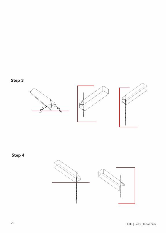
After cutting element C by hand and seeing a fairly mo-derate result ways on how to saw this piece was rese-arched. The first step was to figure out how the wood pieces has to be cut to make its geometry. The most convenient way was to use a circular saw. However the angles and the tilted alignment towards the blade sho-wed that it would not be possible without an tool.
Step 1
Step 2
SAWING
DDU | Felix Dannecker25
Step 3
Step 4

DDU | Felix Dannecker 26

DDU | Felix Dannecker27
The image shows the four cuts that need to be made in order to create the geometry of element C. (from right to left)
DDU | Felix Dannecker 28
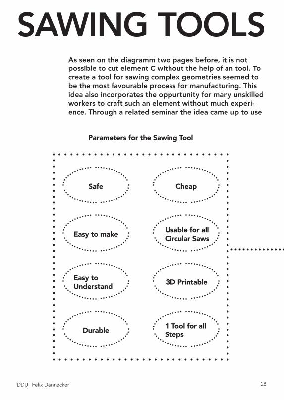
Parameters for the Sawing Tool
Safe
Easy to make
Easy to Understand
Durable1 Tool for all Steps
3D Printable
Usable for all Circular Saws
Cheap
SAWING TOOLSAs seen on the diagramm two pages before, it is not possible to cut element C without the help of an tool. To create a tool for sawing complex geometries seemed to be the most favourable process for manufacturing. This idea also incorporates the oppurtunity for many unskilled workers to craft such an element without much experi-ence. Through a related seminar the idea came up to use
DDU | Felix Dannecker29
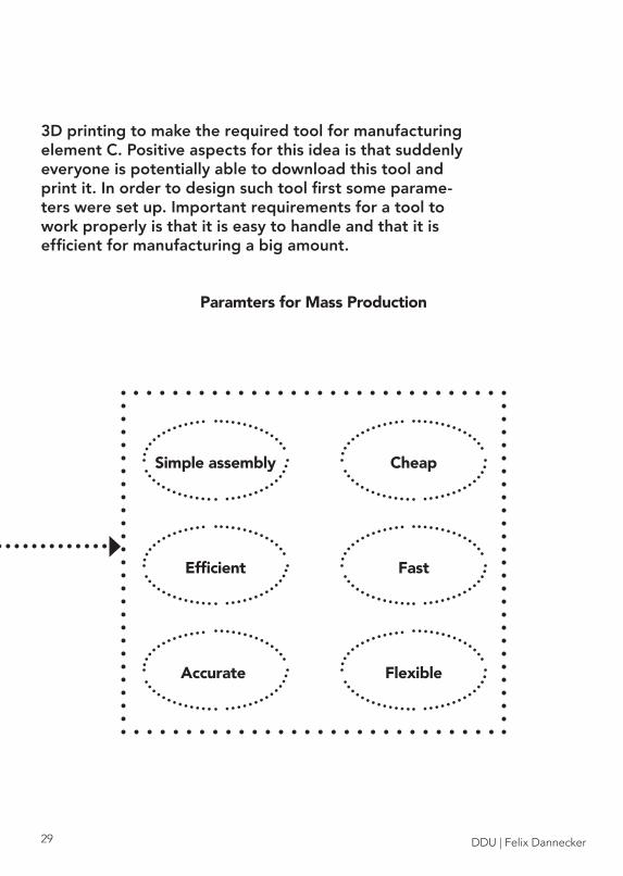
3D printing to make the required tool for manufacturing element C. Positive aspects for this idea is that suddenly everyone is potentially able to download this tool and print it. In order to design such tool first some parame-ters were set up. Important requirements for a tool to work properly is that it is easy to handle and that it is efficient for manufacturing a big amount.
Paramters for Mass Production
Simple assembly
Efficient
Accurate
Fast
Flexible
Cheap

DDU | Felix Dannecker 30
The goal was to create one 3D printed tool that would make it possible to create a complex geometry just by making straight cuts through a table saw. This would make it easy to fabricate such pieces and is a oppurtunity for everyone to make it. In theory one can download these tools in the future and with a basic workshop set up everyone is able to it.
While modelling such tool it turned out that one tool would not be enough for the pieces to be made since for 4 cuts per slat was neccesary. However because it was so much fun making these tools many more were made that makes it ea-sier to manufacture this wood joint. On the following pages a manual will explain the working steps and how these tools were created.
3D PRINTED TOOLS

DDU | Felix Dannecker31
The two cutting tools as seen on the images below were made through a series of studies on how the wood has to be cut in order to create the geometry for element C.The fi rst step was to put the wood elements into a box (blue) and then trim all the sides away intersecting with the wood elements (green). This resulted to a box with holes. The faces were made around the green elements so that they would stay in that position. Further adjustments had to be made such as taking into consideration that the printed tool can-not move besides the blade which would be unsafe.
The images on the left shows this simple process from box to the needed fi xation geometry.

DDU | Felix Dannecker 32
MANUAL
REQURIED MATERIAL:8 WOOD SLATS 45X45MM2 X 8MM PINS

DDU | Felix Dannecker33
ELEMENTS
A
B
C

DDU | Felix Dannecker 34
REQUIRED TOOLS
DRILL
PADSAW

DDU | Felix Dannecker35
GRINDINGMACHINE
CIRCULAR TABLE SAW

DDU | Felix Dannecker 36
3D PRINTED TOOLS
DRILLING TEMPLATEFOR ELEMENTS A + B
DRILLING TEMPLATEFOR ELEMENT C

DDU | Felix Dannecker37
MARKING TOOL FORELEMENT B
MARKING TOOL FORELEMENT A
CUTTING TOOL 2 FORELEMENT C
CUTTING TOOL 1 FORELEMENT C

DDU | Felix Dannecker 38
MAKING ELEMENT A
DRAW ALONG TEMPLATE AND CUT PIECES AWAY

DDU | Felix Dannecker39
DDU | Felix Dannecker 40
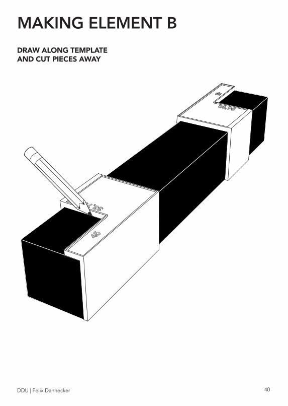
MAKING ELEMENT B
DRAW ALONG TEMPLATE AND CUT PIECES AWAY

DDU | Felix Dannecker41

DDU | Felix Dannecker 42
DRILLING HOLES FOR A + B
STACK ELEMENTS ACCORDING TO IMAGEUSE TEMPLATE TO FIX POSITION DRILL HOLES WITH 8MM DRILLING HEAD

DDU | Felix Dannecker43

DDU | Felix Dannecker 44
MAKING ELEMENT C
ADJUST SAW BLADE HEIGHT TO MARK ON TOOL (27MM)
CAUTION! 5MM GAP BETWEEN TOOL AND SAW BLADE NECCESSARY

DDU | Felix Dannecker45
INSERT WOODPIECE
DDU | Felix Dannecker 46

DDU | Felix Dannecker47
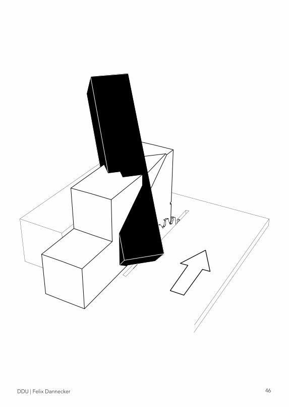
AFTER CUT PULL OUT PIECE ROTATE BY 90°AND PLACE INTO SECOND POSITIONAND REPEAT CUT

DDU | Felix Dannecker 48
7MM
7MM
GRIND EDGE AWAY

DDU | Felix Dannecker49
ADJUST SAW BLADE HEIGHT TO MARK ON TOOL (42MM)
CAUTION! 5MM GAP BETWEEN TOOL AND SAW BLADE NECCESSARY

DDU | Felix Dannecker 50
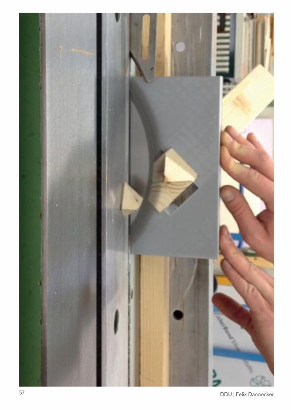
PLACE SLAT INTO SECOND CUTTING TOOL

DDU | Felix Dannecker51
AFTER CUT PULL OUT PIECE ROTATE BY 180°AND PLACE INTO SECOND POSITIONREPEAT CUT
DDU | Felix Dannecker 52
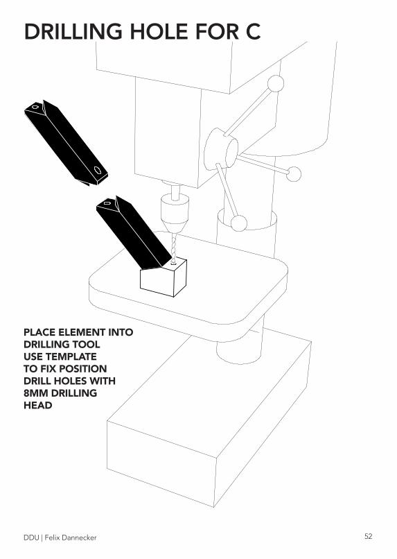
DRILLING HOLE FOR C
PLACE ELEMENT INTO DRILLING TOOLUSE TEMPLATE TO FIX POSITION DRILL HOLES WITH 8MM DRILLING HEAD

DDU | Felix Dannecker53
DDU | Felix Dannecker 54
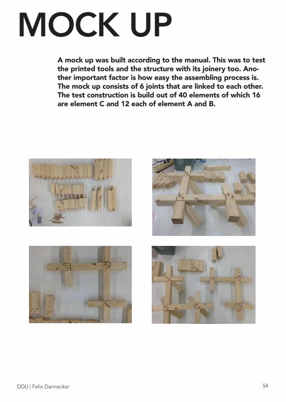
MOCK UPA mock up was built according to the manual. This was to test the printed tools and the structure with its joinery too. Ano-ther important factor is how easy the assembling process is.The mock up consists of 6 joints that are linked to each other. The test construction is build out of 40 elements of which 16 are element C and 12 each of element A and B.

DDU | Felix Dannecker55

DDU | Felix Dannecker 56
EVALUATION3D PRINTED TOOLS
GENERAL
-very helpful for fast manufacturing-easy to handle
-safety issues-to much or too little tolerances
DDU | Felix Dannecker57

DDU | Felix Dannecker 58
EVALUATION CUTTING TOOLS
Both cutting tools turned out to make very accurate cuts.Only approximately 30 minutes were needed to cut 16 ele-ments.
-create universal fixation points for industrial circular saws-adding ergonomic forms to make tool easier to handle-placing marks on tool to make it easier to place wood ele-ments into tools
=
Improvements

DDU | Felix Dannecker59
While preparing the circular saw some safety issues came up. An issue was that it was diffi cult to handle the tools on a big circular saw. It was advised to create fi xation points on the tools to make them more stable, increasing safety. Another issue was that when the wood element was in the tool that it would interfere with the guide rail of the saw causing that for some circular saws improvisations had to be made. Additionally at the beginning it was confusing how the wood elements had to be stuck into the tool. After the fi rst 2 cuts the manual suggest to cut of the edge so that it would fi t perfectly into the second cutting tool. It turned out however that this was very time consuming so we skipped that step and just placed the wood into second tool making it shaky. On the other hand this made the cut-ting process very fast.
Cutting tool for the fi rst two cuts:It is not advisab-le to cut on the right side of the blade

DDU | Felix Dannecker 60
EVALUATION DRILLING TOOLS
Drilling tool for Element A + B
The tools were easy to use and it was very fast to drill many holes in a short time. The wood elements fitted perfectly into the printed elements. There was no issue with tolerances.
DDU | Felix Dannecker61
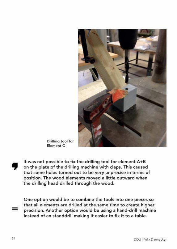
Drilling tool for Element C
It was not possible to fix the drilling tool for element A+B on the plate of the drilling machine with claps. This caused that some holes turned out to be very unprecise in terms of position. The wood elements moved a little outward when the drilling head drilled through the wood.
One option would be to combine the tools into one pieces so that all elements are drilled at the same time to create higher precision. Another option would be using a hand-drill machine instead of an standdrill making it easier to fix it to a table.
=

DDU | Felix Dannecker 62

DDU | Felix Dannecker63
EVALUATION MARKING TOOLS
very simple tool if many woodelements have to be marked for cutting. No ruler or measuring device needed.
mark of pencil has certain thinkness which could lead to some derivations.

DDU | Felix Dannecker 64
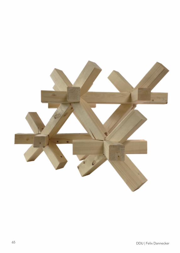
EVALUATIONWOOD STRUCTURE
-easy to assemble-fast assembling
-not as stable as thought-overleap elements make structure shaky -pin too loose
DDU | Felix Dannecker65
DDU | Felix Dannecker 66

DDU | Felix Dannecker67
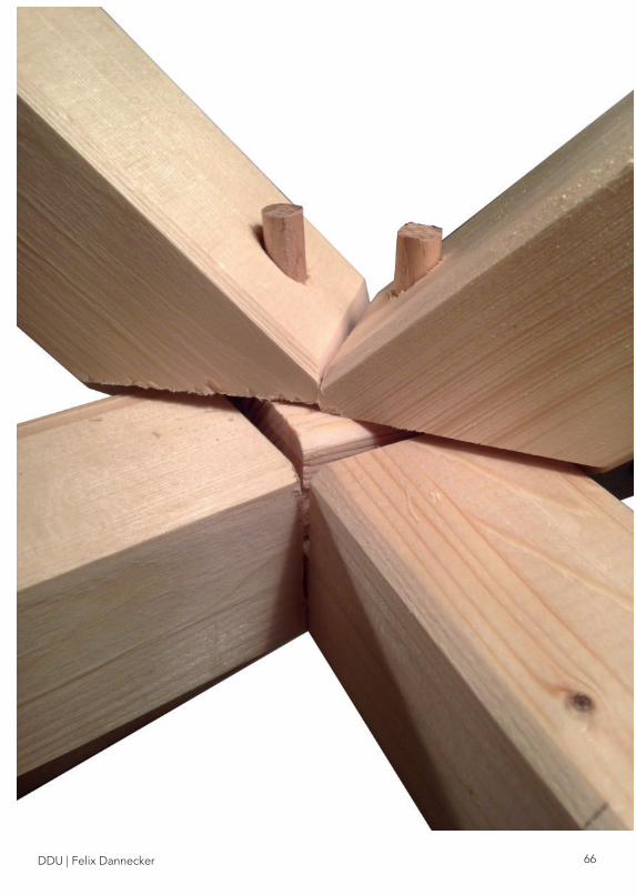
The overleap wood joint of elements A and B is weakening factor for the structure. The elements are hanging through making gaps that should not be there. The pins are not able to press the elements together and holding them into place. This could be the reason why the whole structure is shaking. It could be questions, if this would also occur if this joint seen on the image left would not be an end piece.
Improvements can be made if Elements A + B are not 4 single wood pieces. It would be better if only 2 wood pieces would create a overleap making the croos more stiff and stable. On the otherhand this would be a factor that would make the assembly process more difficult. In terms for manufacturing it would be harder to cut out wood pieces in the midd-le of a wood slat rather than at the end.
OVERLEAP JOINT

DDU | Felix Dannecker 68
DDU | Felix Dannecker69
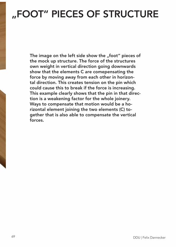
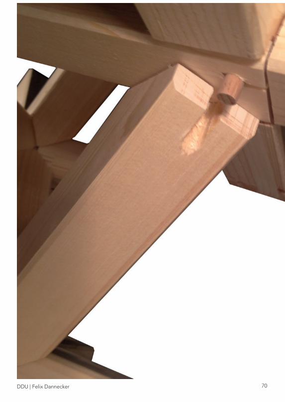
„FOOT“ PIECES OF STRUCTURE
The image on the left side show the „foot“ pieces of the mock up structure. The force of the structures own weight in vertical direction going downwards show that the elements C are comepensating the force by moving away from each other in horizon-tal direction. This creates tension on the pin which could cause this to break if the force is increasing. This example clearly shows that the pin in that direc-tion is a weakening factor for the whole joinery. Ways to compensate that motion would be a ho-rizontal element joining the two elements (C) to-gether that is also able to compensate the vertical forces.
DDU | Felix Dannecker 70

DDU | Felix Dannecker71
POSITION OF HOLE FOR PIN
16 element C woodslats were made for the mock up structure. In 1 case wood broke away due to drilling. This could be lead back to the cheap wood used. But also it shows that over a long period of time this could happen to other elements that are always under force. It is and indication that the hole for the pin is too close towards the edge of the wood slat. To avoid this in the future either a smaller hole is drilled into the wood piece or another position is used so that this does not occur.

DDU | Felix Dannecker 72
CONCLUSIONThe research project initially aimed to manufacture the ele-ments with CNC milling but then gradually moved into a com-pletly different direction. Intially it was aimed that everything would be machine manufactured moving backwards towards handcrafting that is aided through tools made by 3D printing.
After evaluating the 3D printed tools and the construction system generally one can say that the tools were very hel-pfull for manufacturing very precise and accurate elements to assemble. However the created joinery showed many weak-nesses that does not make it to an stable system. This is due to the fact that the pin or bolt did not bring the stability that was assumed. Furthermore it turned out that in some case the big hole for drilling was to close to edges creating damages to the wood. In order to improve this joinery, it is suggested to create to smaller holes next to each other for more stabi-lity. (see image) For further improvement it is neccessary to change the overleap from 4 pieces to 2 making the cross more stiff. This means that element A and B would become the same element. (see image)
The weaknesses of the 3D printed tools were generally pro-blems with tolerances which can be easily fixed. Another point to improve are the two cutting tools. In order to make them universal applicable and safe more functions need to be added to attach them to circular saws. The prototype how it is now is not safe to use for big circular saw machines.
Generally speaking the 3D printed tools could become a very usefull help for craftsman working with wood. Breaking down complex geometries into simple and straight cuts is very time saving and opens up a new field of possibilities for unskilled/untrained or hobby wokers.

DDU | Felix Dannecker73
DDU | Felix Dannecker 74
Bibliography:
Books:
Gramazio & Kohler. The Robotic Touch: How Robots Change Architec-ture. Park Books AG. Zürich, 2014
Gramazio, Kohler & Langenberg. Fabricate: Negotiating Design & Ma-king. gta Verlag, ETH Zürich. Zürich. 2014.
Nakahara Yasuo. Japanese Joinery: A Handbook for Joiners and Carpen-ters. Cloudburst Press Book. Washington. 1983.
Gerschenfeld Neil. Fab: The Coming Revolution on your Desktop-from Personal to Personal Fabrication. Basic Books. 2007.
Papers:
Cheung Kenneth. Digital Cellular Solids: reconfigurable composite mate-rials. Dissertation, MIT, Cambridge. 2012.
Tibbits Skylar. From Digital Materials to Self-Assembly. Article. MIT, Cam-bridge. 2010?
Kanasaki & Tanaka. Traditional Wood Joint System in Digital Fabrication. Article. Keio University. Tokyo.
Reference Projects:
The Robotic Touch: - Piskorec, Dr. Bärtschi, Cadalbert & Kristensen: Spatial Aggrega-tions. P. 342-351 - Piskorec & Ercan: Shifted Frames. P. 352-363 - Knauss, Dr. Kohlhammer: Complex Timber Structures. P.364-377 - Knauss, Dr. Bärtschi, Lyrenmann & Vrontissi: The Sequential Structure. P. 238-249

DDU | Felix Dannecker75
Pictures:
Page 6-7: Cheung Kenneth. Digital Cellular Solids: reconfigurable com-posite materials. Dissertation, MIT, Cambridge. 2012. p.49 + 59
Page 8: apartestudio. Miyajima-tsugi, halved oblique scarf joint. 2016. https://www.instagram.com/p/BITL-XBBSIH/ . 20.02.2017
Page 9: headandcraft. 2013. http://headandhaft.tumblr.com/post/51293249875/another-sneak-peak-of-a-bit-of-joinery-from-a . 20.02.2017
Page 10: Gros Jochen. 50 Digital Wood Joints. 2012. hhttp://jo-chen-gros.de/Jochen_Gros/Newcraft.html . 20.02.2017
Page 11: Gros Jochen. 50 Digital Wood Joints. 2012. hhttp://jochen-gros.de/Jochen_Gros/Newcraft.html . 20.02.2017
Page 12: Gramazio & Kohler. The Robotic Touch How Robots Change Architecture. Complex Timber Structures. Park Books AG. Zürich, 2014. p.367
Page 13: Gramazio & Kohler. The Robotic Touch How Robots Change Architecture. Complex Timber Structures. Park Books AG. Zürich, 2014. p.370
Page 14-15: Klang Laura. Möbel selber bauen mit Scharnieren aus 3D Drucker. 2015. https://deavita.com/lifestyle/designer-stucke/mobel-sel-ber-bauen-3d-drucker.html . 20.02.2017
All other pictures and illustrations made by Felix Dannecker

DDU | Felix Dannecker76