making radios with greasy: gnu radio with … · making radios with greasy: gnu radio with fpgas...
TRANSCRIPT

Making Radios with GReasy: GNU Radio With FPGAs Made
Easy
Ryan L. Marlow
Thesis submitted to the Faculty of the
Virginia Polytechnic Institute and State University
in partial fulfillment of the requirements for the degree of
Master of Science
in
Computer Engineering
Peter M. Athanas, Chair
Carl B. Dietrich
Jeffrey H. Reed
July 29th, 2014
Blacksburg, Virginia
Keywords: GNU Radio, FPGA, Software Defined Radio, SDR, Productivity, Rapid
Compilation
Copyright 2014, Ryan L. Marlow

Making Radios with GReasy: GNU Radio With FPGAs Made Easy
Ryan L. Marlow
(ABSTRACT)
Radio technology is rapidly evolving and as processing capabilties and algorithms become
more complex, the need for alternative compilation and user interface abstraction increases.
Field Programmable Gate Array (FPGA) technology introduces unique reconfigurable hard-
ware architectures that can aid in software defined radio (SDR) design. FPGAs have greater
processing capability than traditional general purpose processors (GPP) found in desktop
workstations. This work builds on an ongoing project, GReasy, that augments a Linux based
open source SDR development platform, GNU Radio, with FPGA processing capabilties. By
delegating processing intensive portions of a radio design to the Xilinx Zynq FPGA architec-
ture, the domain of deployable radios by GNU Radio can be broadened.
Xilinx Zynq, integrates the FPGA fabric and CPU onto a single chip, which eliminates the
need for a controlling host computer; thus, providing a single, portable, low-power, embed-
ded platform. This thesis presents a Zynq capable version of GNU Radio – an open-source
rapid radio deployment tool – with an enhanced flow that utilizes the processing capability of
FPGAs. This work features TFlow – an FPGA back-end compilation accelerator for instant
FPGA assembly. GReasy generates a description of the hardware components that are used
by TFlow for the instant FPGA assembly. Once the FPGA is programmed with a design
based on the description generated by GReasy, modules and the target hardware can be pa-
rameterized to realize an even larger class of applications and further solidify the concept of
rapid assembly of software defined radios.

Acknowledgments
This thesis work would not be possible without the help of numerous people. Great Job!
First and foremost, I would like to thank my advisor, Dr Peter Athanas, for giving me this
opportunity to work on this project that I believe might actually be significant in the near
future. He has given great guidance and help along the way as well.
Thanks to Dr. Reed and Dr. Dietrich for being on my committee.
Thank you everyone in the CCM lab, especially everyone who has played some role in the
GReasy project. Thank you Krzysztof Kepa for your guidance and help on countless issues
and walls that I would not have overcome without you. Thanks to Andrew Love for always
being around to solve my, often user based, TFlow errors. Thanks Ali Asgar Sohanghpurwala
for never failing to lighten the mood in the lab. Thanks to Kevin Lee for making the world’s
coolest demo visualizer. It was very useful in giving demos to lab visitors and abroad at
conferences. Thanks to Kurt Rooks, Chris Dobson, and Minux who all played a role in the
infamous all nighter before the demo back in February.
Thanks to all past members of the CCM lab who helped me along the way. Richard Stroop
and Josh Street who provided guidance during my introduction to the project. Thanks to
Shaver Deyerle and Tony Frangeih for being great friends and their willingness to help me
with any problem.
Finally I’d like to thank my family and friends. Thanks to my parents for supporting me all
through my education and thank you to my roommates at ”The D” for making Blacksburg
all more enjoyable.
iii

Contents
List of Figures viii
List of Tables xi
1 Introduction 1
1.1 Research Contribution . . . . . . . . . . . . . . . . . . . . . . . . . . . . . . 3
1.2 Organization of Thesis . . . . . . . . . . . . . . . . . . . . . . . . . . . . . . 5
2 Background 6
2.1 Reconfigurable Hardware . . . . . . . . . . . . . . . . . . . . . . . . . . . . . 6
2.1.1 Zynq Family . . . . . . . . . . . . . . . . . . . . . . . . . . . . . . . . 7
2.2 Rapid Assembly of Hardware . . . . . . . . . . . . . . . . . . . . . . . . . . 7
2.2.1 Partial Reconfiguration . . . . . . . . . . . . . . . . . . . . . . . . . . 8
2.2.2 Alternative PAR Algorithms . . . . . . . . . . . . . . . . . . . . . . . 8
2.2.3 HMFlow . . . . . . . . . . . . . . . . . . . . . . . . . . . . . . . . . . 9
2.2.4 QFlow . . . . . . . . . . . . . . . . . . . . . . . . . . . . . . . . . . . 10
2.2.5 TFlow . . . . . . . . . . . . . . . . . . . . . . . . . . . . . . . . . . . 12
iv
2.3 Software Defined Radio . . . . . . . . . . . . . . . . . . . . . . . . . . . . . . 13
2.3.1 GNU Radio . . . . . . . . . . . . . . . . . . . . . . . . . . . . . . . . 15
2.3.2 Related Modifications of GNU Radio . . . . . . . . . . . . . . . . . . 16
2.4 Early GReasy Work . . . . . . . . . . . . . . . . . . . . . . . . . . . . . . . . 17
3 GReasy Made Easier 20
3.1 Flexible Flowgraph . . . . . . . . . . . . . . . . . . . . . . . . . . . . . . . . 22
3.1.1 Flowgraph Conversion Algorithm . . . . . . . . . . . . . . . . . . . . 24
3.2 Parameterized Modules . . . . . . . . . . . . . . . . . . . . . . . . . . . . . . 29
3.3 Multiple Clocks . . . . . . . . . . . . . . . . . . . . . . . . . . . . . . . . . . 34
4 Transition to Zynq and Beyond 36
4.1 Zynq Static Design . . . . . . . . . . . . . . . . . . . . . . . . . . . . . . . . 36
4.2 Bare-metal Firmware Exploration . . . . . . . . . . . . . . . . . . . . . . . . 39
4.3 Embedded Linux . . . . . . . . . . . . . . . . . . . . . . . . . . . . . . . . . 43
4.3.1 Embedded Linux Enabled Partial Reconfiguration . . . . . . . . . . . 43
4.4 Zynq Enabled Use Models . . . . . . . . . . . . . . . . . . . . . . . . . . . . 45
4.4.1 Desktop Host Traditional GNU Radio . . . . . . . . . . . . . . . . . 45
4.4.2 Desktop Host GReasy . . . . . . . . . . . . . . . . . . . . . . . . . . 45
4.4.3 Embedded Traditional GNU Radio . . . . . . . . . . . . . . . . . . . 46
4.4.4 Embedded GReasy . . . . . . . . . . . . . . . . . . . . . . . . . . . . 46
4.4.5 Multiple Models and Devices . . . . . . . . . . . . . . . . . . . . . . 46
v

5 Merging with GNU Radio 3.7 48
5.1 Updated File/Directory Structure . . . . . . . . . . . . . . . . . . . . . . . . 49
5.2 Build Tools . . . . . . . . . . . . . . . . . . . . . . . . . . . . . . . . . . . . 52
5.3 Module Registration . . . . . . . . . . . . . . . . . . . . . . . . . . . . . . . 53
6 Implementations and Results 56
6.1 Demo Platforms . . . . . . . . . . . . . . . . . . . . . . . . . . . . . . . . . . 56
6.1.1 ADC/DAC Capabilities . . . . . . . . . . . . . . . . . . . . . . . . . 58
6.1.2 Cognitive Radio Platform . . . . . . . . . . . . . . . . . . . . . . . . 59
6.2 GReasy Hardware Modules . . . . . . . . . . . . . . . . . . . . . . . . . . . . 60
6.2.1 BPSK Demod Design . . . . . . . . . . . . . . . . . . . . . . . . . . . 60
6.2.2 Zigbee . . . . . . . . . . . . . . . . . . . . . . . . . . . . . . . . . . . 60
6.2.3 Tuner . . . . . . . . . . . . . . . . . . . . . . . . . . . . . . . . . . . 61
6.2.4 DES Encryption . . . . . . . . . . . . . . . . . . . . . . . . . . . . . 62
6.2.5 Cube Experiments . . . . . . . . . . . . . . . . . . . . . . . . . . . . 62
6.3 Results . . . . . . . . . . . . . . . . . . . . . . . . . . . . . . . . . . . . . . . 63
7 Conclusion 68
7.1 Future Work . . . . . . . . . . . . . . . . . . . . . . . . . . . . . . . . . . . . 69
Bibliography 70
A Program Source 75
A.1 GNU Radio Runtime Code . . . . . . . . . . . . . . . . . . . . . . . . . . . . 75
vi

A.1.1 Entry Classes . . . . . . . . . . . . . . . . . . . . . . . . . . . . . . . 75
A.1.2 Parameter Module . . . . . . . . . . . . . . . . . . . . . . . . . . . . 80
vii

List of Figures
2.1 HMFlow design assembly paradigm . . . . . . . . . . . . . . . . . . . . . . . 10
2.2 QFlow design assembly paradigm . . . . . . . . . . . . . . . . . . . . . . . . 11
2.3 TFlow Use Model . . . . . . . . . . . . . . . . . . . . . . . . . . . . . . . . . 13
2.4 Generalized Software Defined Radio Platform . . . . . . . . . . . . . . . . . 14
2.5 Screenshot of a SDR design created in GNU Radio Companion, the Graphical
front-end to GNU Radio. . . . . . . . . . . . . . . . . . . . . . . . . . . . . 16
2.6 GReasy design flow . . . . . . . . . . . . . . . . . . . . . . . . . . . . . . . 18
3.1 GReasy is composed of an enhanced GNU Radio that generates an EDIF
netlist. That netlist is passed on to TFlow, a backend rapid bitstream genera-
tion tool built on top of TORC, which generates a full programmable bitstream. 22
3.2 Where the flowgraph converter/Entry API fits into this scheme. The flow-
graph populates objects in the Entry API and is then written to a ”.dat” file.
That ”.dat” is then converted to an EDIF netlist resembling the GNU Radio
flowgraph blocks and connections. . . . . . . . . . . . . . . . . . . . . . . . 25
viii

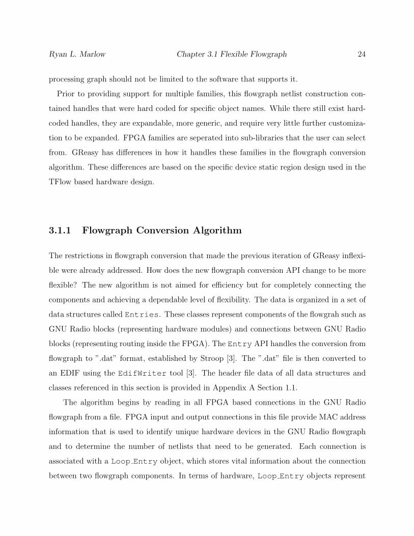
3.3 Steps of the flowgraph conversion algorithm. The blocks are represented in
the EDIF generation algorithm as Cell Entry objects. The connections
between the blocks are represented as Loop Entry objects. Smaller numbers
represent unique identifiers assigned to connections. . . . . . . . . . . . . . 27
3.4 Parameterized modules are connected together sequentially. Parameter data
is consumed by each module in the chain until the end of the chain of modules. 30
3.5 Parameterized Modules can be selected and display module properties. These
properties are the user defined parameters that can be configured before or
during run-time. . . . . . . . . . . . . . . . . . . . . . . . . . . . . . . . . . 31
3.6 Variable Control Blocks can be used to configure parameters while the com-
ponents in the flowgraph are processing radio signals. . . . . . . . . . . . . 32
3.7 Data and configuration Ethernet packet structure. . . . . . . . . . . . . . . 33
4.1 Development board targeted platform for the Zynq 7-series FPGA family.
Linux Gizmos, ”xilinx zc706 baseboard callouts.” [Online]. Available: http://files.lin
uxgizmos.com/xilinx-zc706-baseboard-callouts.jpg. Used under fair use, 2014. 37
4.2 Block Diagram of the FPGA including the ARM and FMCOMM ADC/DAC
board. . . . . . . . . . . . . . . . . . . . . . . . . . . . . . . . . . . . . . . . 38
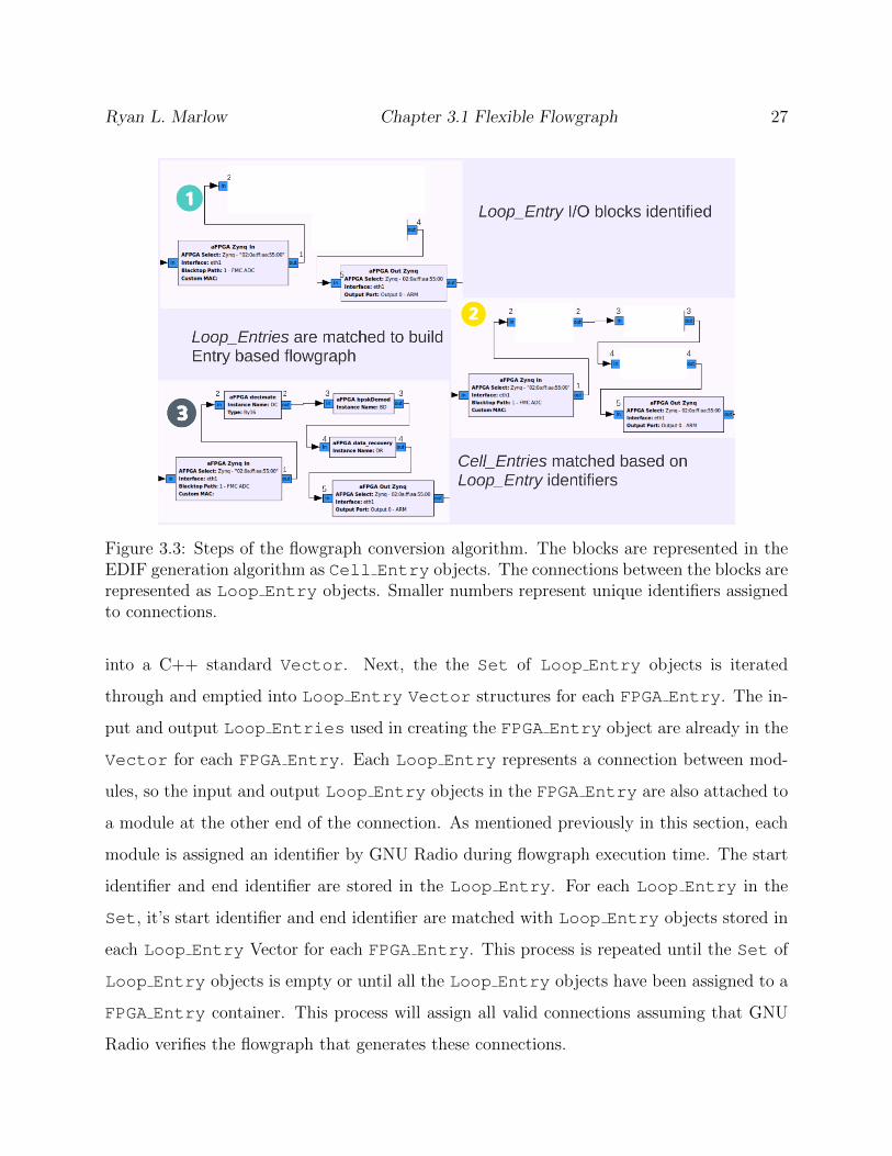
4.3 Flow of bare-metal firmware code . . . . . . . . . . . . . . . . . . . . . . . . 40
4.4 Raw Ethernet packet communication. 0xDEAD packets are used to configure
the target device. . . . . . . . . . . . . . . . . . . . . . . . . . . . . . . . . 41
4.5 Partial Reconfiguration flow . . . . . . . . . . . . . . . . . . . . . . . . . . . 44
4.6 Multiple uses and models can be targeted in a single flowgraph. . . . . . . . 47
5.1 File structure of GNU Radio 3.7 with GReasy additions. . . . . . . . . . . . 50
ix

6.1 Demo Platform Block Diagram. Mouser, ”AD-FMCOMMS1-EBZ” [Online].
Available: http://www.mouser.com/images/adi/images/AD-FMCOMMS1-EBZ.
jpg. Used under fair use, 2014. Silica, ”Silica Xilinx Zynq 7000 SoC ZC706
Eval Kit icon” [Online]. Available: http://www.silica.com/fileadmin/02 Products/
Productdetails/Xilinx/Silica Xilinx -Zynq-7000-SoC-ZC706-Eval-Kit-icon.jpg,
Used under fair use, 2014. Zedboard, Z̈edBoard RevA[̈Online]. Available:
http://www.zedboard.org/sites/default/files/product spec images/ZedBoard Rev
A sideA 0 0(1) 0.jpg. Used under fair use, 2014. Photo by Kevin Lee. Used
under fair use, 2014. . . . . . . . . . . . . . . . . . . . . . . . . . . . . . . . 57
6.2 ADC Block Diagram . . . . . . . . . . . . . . . . . . . . . . . . . . . . . . . 58
6.3 Cognitive Radio Test Bed. The stack of XC7Z020’s are fully connected to one
another through the FMC to SATA interfaces. Photo by Ryan Marlow, 2014. 59
6.4 The Cube: Demo visualizer. In this image, showing randomized colors. Photo
by Ryan Marlow, 2014 . . . . . . . . . . . . . . . . . . . . . . . . . . . . . . 63
x

List of Tables
6.1 Resource Usage of Precompiled Modules . . . . . . . . . . . . . . . . . . . . 64
6.2 Assembly Time Using Traditional Vendor Tools . . . . . . . . . . . . . . . . 65
6.3 Assembly Time with GReasy Desktop without binary conversion . . . . . . . 65
6.4 Assembly Time with GReasy Desktop . . . . . . . . . . . . . . . . . . . . . 65
6.5 GReasy Modules Precompilation Time . . . . . . . . . . . . . . . . . . . . . 66
6.6 Assembly Time with GReasy Embedded . . . . . . . . . . . . . . . . . . . . 67
xi

Glossary
ADC Analog to Digital Converter.
BPSK Binary Phase Shift Keying.
DAC Digital to Analog Converter.
DES Data Encryption Standard.
DMA Direct Memory Access.
EDIF Electronic Design Interchange Format.
FMC FPGA Mezzanine Card.
FPGA Field Programmable Gate Array.
GPP General Purpose Processor.
GRC GNU Radio Companion.
HDL Hardware Descriptive Language.
LPC Low Pin Count.
SATA Serial AT Attachment.
xii

SDR Software Defined Radio.
SWIG Simplified Wrapper and Interface Generated.
TORC Tools for Open Reconfigurable Computing.
USRP Universal Softare Radio Peripheral.
XDL Xilinx Design Language.
XML Extensible Markup Language.
xiii

Chapter 1
Introduction
Software defined radio is the inevitable future of radio design. Using SDR principles, en-
gineers can develop reconfigurable radio systems with a wide range of capabilities. Open
source tools, such as GNU Radio, allow users to test and prototype radio designs by ap-
plying the flexibility and versatility of SDR through a well-established design methodology
that is intuitive for radio designers [1]. GNU Radio provides instant gratification in the
transition of modeling a radio to the deployment of a fully-functional radio. However, due
to the limited computational and I/O capacity of a desktop computer, there is a limited
scope of radios that GNU Radio is capable of prototyping. One solution is to provide a
framework for augmenting the desktop with additional processing hardware, such as FP-
GAs. GReasy is a software extension to GNU Radio that adds the computational benefits
of Field Programmable Gate Array (FPGA) acceleration without the pain of slow FPGA
compile times [2, 3]. A broader class of radios can be realized with GReasy by augmenting
the GNU Radio platform with FPGAs, yet the instant gratification nature of GNU Radio is
preserved.
FPGAs take a considerable time to design, compile, and program. The design process
is composed of a front-end design entry phase, and a back-end design compilation phase.
Research has shown that higher levels of abstraction can assist in the productivity of the
1

Ryan L. Marlow Chapter 1. Introduction 2
design entry phase [4]. Radio designers might not necessarily be familiar with HDL or com-
plicated vendor tools required to target the accelerated processing capabilities of FPGAs.
These designers require some form of abstraction to use these capabilities. The methodology
proposed in this thesis is in-line with many contemporary uses of abstraction: high-level
domain-specific parameterizable signal processing blocks are used to model radio processing
behavior. This not only aids in design productivity, but also extends the usability of FPGAs
to non-FPGA experts, such as radio designers.
In regards to design iteration and turns-per-day, the FPGA back-end design compilation
process is often the bottleneck. There are vendor-provided flows (Xilinx in this case), such
as Partial Reconfiguration flow or the now obsolete Modular Design flow, that can reduce
the burden of compile times, yet often impose architectural constraints, restrict how much
of the design can change, and have steep learning curves. Furthermore, compile times still
remain in the minutes-to-hours range for a moderate size FPGA, or even hours-to-days for
larger designs. In GReasy, an alternative method is used for bitstream generation. GReasy
utilizes TFlow for back-end bitstream construction, which places and routes parameterized
pre-compiled modules into an FGPA bitstream, and does so in a few seconds time – well
within the expectation of a software-only flow [5].
Within the GReasy environment, FPGA-based processing modules are added to the GNU
Radio module library. This allows a user to arbitrarily add optimized hardware and soft-
ware modules to a given design, which further supports unskilled users in using hardware
in their designs. When the radio designer is ready to prototype their design, precompiled
components are stitched together and a full FPGA design is generated in seconds.
GNU Radio has been developed primarily as a desktop development / exploration envi-
ronment. With the advent of SoC-FPGA platforms, FPGAs themselves can become their
own autonomous development environment. By running GReasy on an ARM within a Zynq
device [6], a fully embedded / autonomous mode for GNU Radio is realized. This ARM
is capable of running an embedded Ubuntu, which in turn can support the run-time com-
ponents of GNU Radio and TFlow, providing a solution that can provide full (or partial)

Ryan L. Marlow Section 1.1 Research Contribution 3
bitstream generation in an untethered platform.
As a result of this added flexibility, a number of new FPGA / hardware / software use-
models are created. A radio designer can (a) create radio blocks that target software-only
execution on the desktop, or (b) the desktop can be loosely augmented with FPGAs, or (c)
GNU Radio modules can be directed to run on the embedded ARM cores, or (d) the ARM
cores can be accelerated with the tightly-coupled reconfigurable fabric. Furthermore, a sin-
gle radio design can seamlessly be spread across multiple FPGAs and multiple processors.
In all of these cases, the bitstreams for all FPGAs, all software tasks, including all implicit
software-FPGA interactions, can all co-exist in a single radio specification (as a GNU Radio
Companion diagram, or as a Python script).
1.1 Research Contribution
This thesis presents work done on an ongoing project, GReasy. GReasy is a modified GNU
Radio that enables radio designers to target hardware processing modules, integrated seam-
lessly into the GNU Radio user interface. The goal of this thesis work is to improve on this
model by providing additional enhancements to GReasy.
In previous iterations of GReasy, there were some capabilities that were noticeably lacking.
A crucial capability that was lacking is parameterizing blocks for more versatile customiza-
tion and more precise rapid prototyping. With the ability to parameterize blocks, a user can
further customize a radio design after the FPGA has been configured with the design. This
cuts down on turn around time between prototype iterations while expanding the exploration
space, and it cuts down on the library components needed to cover a wide array of possible
radio designs.
To ensure a flexible radio system in GReasy, multiple FPGAs can be connected together
to perform more complex computations and hardware configurations. It is desirable to have
all possible connection configurations accounted for to ensure maximum flexibility. This

Ryan L. Marlow Section 1.1 Research Contribution 4
required a re-write to the flowgraph conversion code that generates an EDIF (Electronic
Design Interchange Format) from the GNU Radio flowgraph. Some improvements include
the ability to recognize multiple FPGAs, multiple FPGA families/device types, multiple in-
put and output blocks in the flowgraph representing multiple input and output ports in the
FPGA design, and multiple clocking options.
One motivation to adding this additional flexibility in EDIF construction was the addi-
tion of a new target hardware, the Xilinx Zynq platform. To ease the transition to the new
hardware, a number of test designs were constructed that incorporated the previous Virtex-5
FPGA stack with additional Xilinx Zynq boards connected together via Ethernet [7]. A
new block library was constructed to represent these Zynq hardware processing components
and various iterations of a static design were made testing different capabilities of the new
hardware platform.
A final contribution given in this thesis is upgrading from GNU Radio 3.3 to 3.7. For a
project like GReasy, that is built on top of open source tools like GNU Radio, it is important
to keep the code integration up to date with the code base. This is important so GReasy
can more easily be released and accessible to the greater GNU Radio community.
A comprehensive list of these contributions are given below:
1. Development of a cleaner and more flexible construction of the netlist data structures
from the GNU Radio flowgraph including additional capabilities: multiple FPGAs,
multiple FPGA families, multiple I/O flowgraph blocks per device
2. Development of a framework for parameterizing FPGA hardware processing blocks in
a hardware/software co-design for increased versatility
3. Option for a design to have multiple clock domains within the GReasy framework
4. Creation of a new GReasy block library representing Zynq hardware processing compo-
nents and framework to expand the block library to include future device components

Ryan L. Marlow Section 1.2 Organization of Thesis 5
5. Added support for a new target hardware: Xilinx Zynq FPGA
6. Updated GReasy from the outdated GNU Radio 3.3 to new GNU Radio 3.7.
1.2 Organization of Thesis
This thesis is organized in the following manner. Chapter 2 discusses a variety of back-
ground topics including FPGA technology and FPGA rapid compilation tools. A definition
and overview of Software Defined Radio is covered and the SDR rapid prototyping tool,
GNU Radio. A review of some notable modifications to GNU Radio will be provided and
finally an introduction to the previous modifications to GNU Radio, known as GReasy, that
this thesis work is built on. Chapter 3 discusses improvements to the GReasy framework
that were made as the core contributions in this thesis. Chapter 4 details the transition of
GReasy to a new hardware platform, the Xilinx Zynq. There are a number of aspects of this
new hardware that differ from the previous hardware target in addition to improvements
made to the GReasy software codebase that were necessary to facilitate this transition. In
addition to a transition to a new hardware, there was also a push to upgrade GReasy to
an up to date version of GNU Radio. This transition is explained in Chapter 5. Chapter
6 details the new demo platform, lists and explains some example designs, and presents ex-
perimental results. Chapter 7 concludes the thesis and provides some additional work that
can be done to improve the current platform.
Chapter 2
Background
This chapter will discuss a variety of background topics related to this project. First, re-
configurable hardware-specifically Field Programmable Gate Arrays (FPGAs)- will be intro-
duced. Much research has gone into increasing productivity around FPGAs, which usually
involves decreasing compilation times in a variety of ways. The next section will introduce
and explore key concepts of Software Defined Radio and the development platform, GNU
Radio. Finally, some related modifications to GNU Radio will be reviewed and the previous
use model of GReasy will be introduced.
2.1 Reconfigurable Hardware
FPGAs are hardware components meant to be configured by a designer, often using a hard-
ware description language (HDL) such as VHDL or Verilog. FPGAs are an integrated circuit
made up of generalized logical components and routing connections to the components that a
designer describes using an HDL. This HDL goes through a series of steps to generate a pro-
gram file, also known as a bitstream, that is used to configure or reconfigure an FPGA. These
6

Ryan L. Marlow Chapter 2.2 Rapid Assembly of Hardware 7
steps are: synthesis, translation, mapping, placement and routing (PAR) and bitstream gen-
eration. The bitsream generated in the last step is the programming file used to configure
the FPGA with the target design. FPGAs have a wide variety of uses including digital sig-
nal processing applications in software defined radio such as the work presented in this thesis.
2.1.1 Zynq Family
Many FPGAs have the programming capability to include an embedded processor on the
fabric such as Xilinx Microblaze, using the FPGA logic resources [8]. The Xilinx Zynq fam-
ily includes embedded ARM CPU sharing the same fabric as a reconfigurable region [6]. The
Zynq is part of the Series 7 Xilinx FPGA family, which also includes the Artix-7, Kintex-7
and Virtex-7. The ARM on the same fabric enables a user to develop applications on the
ARM with greater processing capabilities connected directly to the FPGA all on a single
platform. The ARM platform can be an embedded Linux platform or bare-metal firmware
depending on the user application desired [9].
2.2 Rapid Assembly of Hardware
The FPGA technology roadmap closely follows Moore′s law and is benefiting from the in-
creased logic density available with new process technologies; however, FPGA designers′
productivity remains low. The FPGA design process is time consuming, can have a large
turnaround time, and often requires low-level hardware design skills [10]. For larger designs,
it can take many minutes, many hours, or many days to generate a bitstream from HDL.
These large turn-around times can hinder the design process and consequently diminish the
accessibility of hardware. This section will explore some of the alternative design flows that
have been attained through alternative algorithms or creating a more software-like modular

Ryan L. Marlow Chapter 2.2 Rapid Assembly of Hardware 8
flow in design compilation.
2.2.1 Partial Reconfiguration
FPGA vendors do offer alternative means of reconfiguration, such as Xilinx partial recon-
figuration (PR). In PR, the FPGA is segmented into regions that can each individually be
reprogrammed. This enables reconfiguration of portions of the device while different portions
are running; thus, reducing the time needed to reconfigure portions of the device [11]. One
can even target the Xilinx Zynq platform for partial reconfiguration using the embedded
ARM chip as a host [12]. While the PR flow allows a design to switch quickly, it can only
switch between a set of pre-determined functions. While partial reconfiguration does not
affect the design compile time, it provides a solution for more rapidly changing the func-
tionality of a device. Despite this, it can be limiting and cumbersome to implement partial
reconfiguration in an FPGA design and the initial design still follows the traditional vendor
flow. Some of these limitations include requiring fixed size and location reconfigurable slots
with fixed I/O macros. These limitations highlight the need for detailed knowledge of the
implementation tools when using partial reconfiguration in a design and for this reason, re-
search has been done to speed up these compile times in alternative ways.
2.2.2 Alternative PAR Algorithms
Much work has been done on speeding up bitstream compilation times for FPGAs. Previous
work focuses on faster PAR algorithms but often they have limiting constraints [13, 14].
There is often a measurable quality trade off between using these faster PAR algorithms as
well, specifically the faster a placer is, the greater the critical path delay, greater the decrease
in quality of that placement.

Ryan L. Marlow Chapter 2.2 Rapid Assembly of Hardware 9
2.2.3 HMFlow
Alternative design flows have been used in an effort to speed up this process of compilation.
HMFlow is an alternative design flow that enables more rapid prototyping of hardware
designs. HMFlow uses previously synthesized, placed and routed circuits in the form of a hard
macro pre-compiled library to decrease bitstream generation time [15]. These precompiled
components are implemented with conventional Xilinx tools. Xilinx System Generator is
used as a front-end for constructing a design made up of hard macro components, though
any design entry tool could be used. The process of HMFlow is as follows:
1. The user creates a System Generator design featuring precompiled Hard Macro blocks,
or components.
2. HMFlow parses the design file generated by System Generator to extract information
about the Hard Macro blocks.
3. The blocks in the System Generator design are matched to Hard Macro components
from the precompiled library.
4. After initial synthesis of the hard macro-bound design, placement contraints are de-
termined of the actual resource utilization on the device.
5. The design stitcher, combines the hard macros components together into a single im-
plementation. This involves the creation of nets based on the connections present in
System generator. The design stitcher also inserts appropriate I/O buffers and clock
generation circuitry.
6. A custom router connects the hard macros together to ensure the routing inside the
hard macros remains intact.

Ryan L. Marlow Chapter 2.2 Rapid Assembly of Hardware 10
Figure 2.1: HMFlow design assembly paradigm
The final output of the design is a placed and routed implementation, linked together to
create a full design in the form of Xilinx Design Language, XDL. While promising, HMFlow
is held back by having to convert those hard macros into a properly formatted netlist that
takes considerable time and the XDL generated as a final design requires an additional stage
of conversion to generate the programmable bitstream.
2.2.4 QFlow
Another rapid flow, QFlow, exploits the logic variance and hierarchy as a means to increase
FPGA productivity [16]. The design is split into two classes, the invariant set and an
evolving set. The invariant set contains logic components in the design that will not change,
such as memory or Gigabit Ethernet interfaces. The evolving set contains components in
the design that will change and be prototyped. The overall design is split into four phases:
design partitioning, invariant set implementation, evolving set implementation, and design
assembly.
The first step in the implementation process is the design partitioning phase. In this phase,
the design is partitioned into the two classes, invariant and evolving logic. The invariant set
implementation allocates a sandbox, a region on the device that will host the evolving logic.
The sandbox needs to satisfy a maximum resource requirement of the evolving logic. In the

Ryan L. Marlow Chapter 2.2 Rapid Assembly of Hardware 11
Figure 2.2: QFlow design assembly paradigm
evolving set implementation process, every module is separately implemented. The modules
are represented as a structure without specifying absolute placement on the device. Each
module is cached to a library for later retrieval. Finally the design is assembled by placing
the evolving set components in the defined sandbox region allocated in the invariant set.
Connections between components are routed to finalize the design.
QFlow implements a custom placer that rapidly decides where to place pre-synthesized
modules on the FPGA. It then uses the Xilinx router. This routing is optimized with a
standard Xilinx algorithm, so that overhead remains intact. The main improvement here is
the faster placing and the concept of stitching pre-synthesized modules together to generate
a full design. QFlow can be seen as a precursor to TFlow.

Ryan L. Marlow Chapter 2.2 Rapid Assembly of Hardware 12
2.2.5 TFlow
TFlow is the rapid bitstream generation tool used by GReasy. TFlow continues the paradigm,
established by QFlow, of splitting the design into two distinct regions. In TFlow, these classes
are referred to as the static and dynamic regions. TFlow is built on top of TORC, an API
for user manipulation of EDIF and XDL files as well as bitstream packets, and uses a library
of pre-compiled modules and associated meta-data, enabling bitstream-level assembly of de-
sired designs that can occur in a fraction of the time of traditional back-end tools [17, 5].
This is done by splitting the hardware design into two distinct phases. In the first phase,
the designer creates modules with specific purpose and functionality and adds them to the
module library. In the second phase, the design bitstream is assembled from precompiled
modular bitstream components from the library.
In the first phase of the flow, a hardware engineer designs individual modules using an
ordinary hardware design flow. Then, after testing and verifying the module design, the mod-
ule is registered to the TFlow module library. This registration process involves generating
the modules bitstream as well as extracting metadata from the module including resource
constraints, and valid placements of the module on the hardware device. This metadata is
used by TFlow to speed up the bitstream assembly process in the second phase.
In the second phase, the user creates a design composed of individual components from
the module library. Much like the GNU Radio software library of processing blocks, TFlow
has a precompiled library of hardware modules that the user can select. TFlow stitches
the module bitstreams together and combines them with an additional static bitstream to
create a full bitstream for the target FPGA in a matter of seconds. Right now, targeted
FPGA architectures of TFlow include the Virtex-5 family as well as the Zynq family. TFlow
can be easily expanded to other Xilinx FPGA family architectures due to certain generic
components of the TFlow toolchain.
These two phases can be mixed to more rapidly prototype and test individual modules
to cut down on testing and verification time in the module design process. As opposed to
recompiling an entire design in a traditional vendor flow, an individual module can be recom-
Ryan L. Marlow Chapter 2.3 Software Defined Radio 13
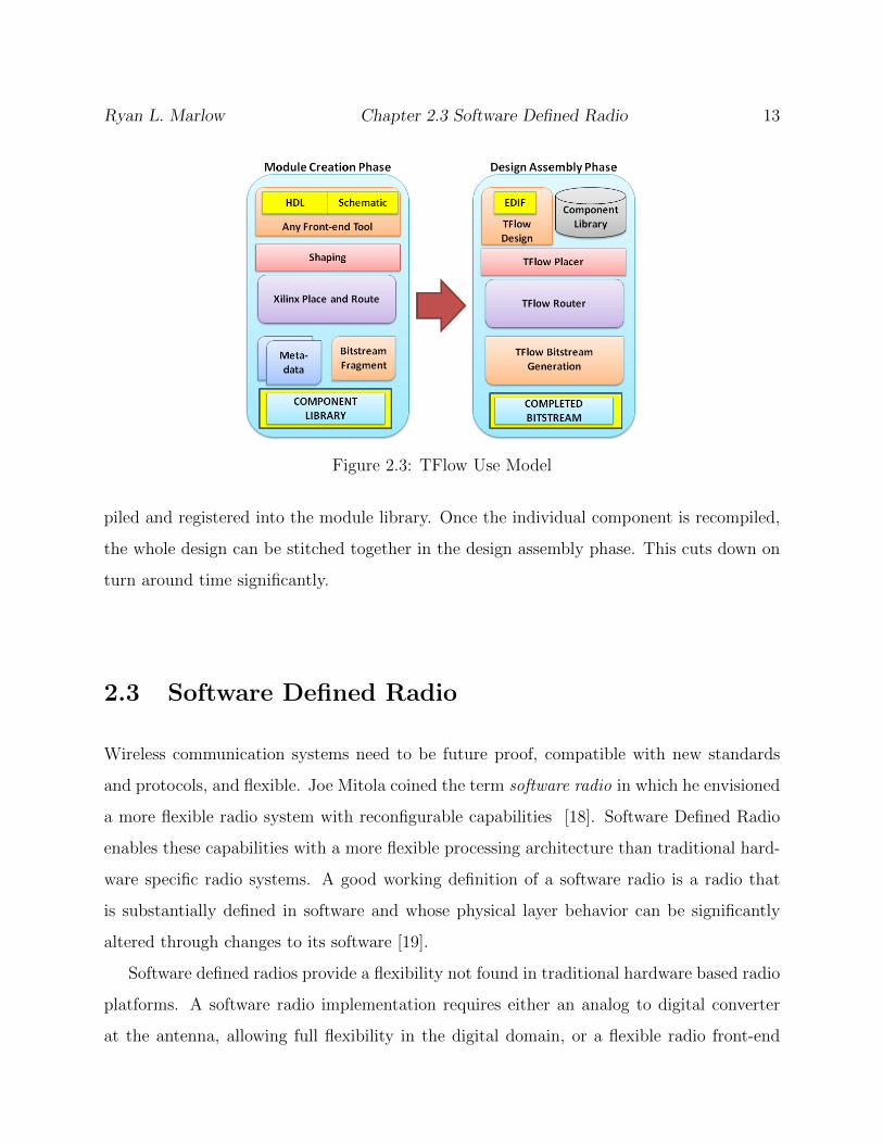
Figure 2.3: TFlow Use Model
piled and registered into the module library. Once the individual component is recompiled,
the whole design can be stitched together in the design assembly phase. This cuts down on
turn around time significantly.
2.3 Software Defined Radio
Wireless communication systems need to be future proof, compatible with new standards
and protocols, and flexible. Joe Mitola coined the term software radio in which he envisioned
a more flexible radio system with reconfigurable capabilities [18]. Software Defined Radio
enables these capabilities with a more flexible processing architecture than traditional hard-
ware specific radio systems. A good working definition of a software radio is a radio that
is substantially defined in software and whose physical layer behavior can be significantly
altered through changes to its software [19].
Software defined radios provide a flexibility not found in traditional hardware based radio
platforms. A software radio implementation requires either an analog to digital converter
at the antenna, allowing full flexibility in the digital domain, or a flexible radio front-end

Ryan L. Marlow Chapter 2.3 Software Defined Radio 14
Figure 2.4: Generalized Software Defined Radio Platform
that can handle a wider range of carrier frequencies [19]. Figure 2.4 shows a model of
practical software radio. The SDR receiver begins with a smart antenna with a wide and
programmable range in carrier frequencies and domains. That received analog signal is then
converted to the digital domain and converted to a specified sample rate and pre-filtered.
The core processing occurs in the flexible digital domain with software or other flexible ar-
chitecture. To transmit a signal, the process is reversed. The signal is converted from digial
to analog and transmitted with some flexible and programmable radio front-end hardware.
Software defined radio architectures allow reusable and reconfigurable radio systems and
give radio designers the capability to implement a wide array of techniques and interfaces
on the fly. Modern radio systems almost require these capabilities, specifically the need to
be agile in switching between communication standards. The software radio approach re-
sults in compact and power-efficient designs that minimize the number of systems needed to

Ryan L. Marlow Chapter 2.3 Software Defined Radio 15
perform multiple functions. A flexible architecture allows for improvements and additional
functionality without the need to upgrade all the hardware in the system.
2.3.1 GNU Radio
GNU Radio is an open-source development toolkit in which radio signal processing appli-
cations can be prototyped in a simulated software environment or with real RF hardware.
GNU Radio comes with a graphical front-end, GRC (GNU Radio Companion), that can
help a radio designer create a visual representation of the flow of their design [20]. Figure
2.3 shows an example flowgraph in GRC composed of filter and resampling blocks as an
example of some of the capabilities of GNU Radio. Many radio engineers are familiar with
GNU Radio or if they are not, are familiar with its general purpose of rapid prototyping
radio designs.
A GNU Radio design is composed of signal processing blocks connected through input and
output ports to create a flowgraph structure. It uses a combination of C++ and Python to
run SDR applications. The signal processing is expressed in C++ while connecting blocks
together in the flowgraph design, is in Python. C++ code can be connected with Python
with SWIG [21]. SWIG creates wrapper functions in Python to use C++ code with Python
scripts. Each processing block has associated metadata such as input and output port lists,
dynamic parameters, and documentation about blocks that are all stored in XML files for
each block. When a radio designer creates a flowgraph in GRC composed of these blocks, a
Python script is generated that specifies the functions that will be executed and the order
of operation.

Ryan L. Marlow Chapter 2.3 Related Modifications of GNU Radio 16
Figure 2.5: Screenshot of a SDR design created in GNU Radio Companion, the Graphicalfront-end to GNU Radio.
2.3.2 Related Modifications of GNU Radio
GNU Radio is constantly moving forward with new enhancements in both newly developed
software blocks and hardware acceleration capabilities, such as what this thesis suggests.
Software blocks often add some unavailable functionality to GNU Radio. Hardware acceler-
ation can replace already existent functionality and improve it or enable new functionality
through improved performance.
The Kansas University Agile Radio (KUAR) developed by the Information Technology
and Telecommunications Center at Kansas University is a project that improves GNU Ra-
dio [22]. KUAR is a heterogeneous system composed of a GPP and a Virtex-II FPGA,

Ryan L. Marlow Chapter 2.4 Previous GReasy Use Model 17
where a majority of the signal processing is performed on the FPGA. This enables advanced
research in wireless radio networks, dynamic spectrum access, and cognitive radios. The
KUAR system has a number of use models including purely reconfigurable hardware based
SDR platform, purely software SDR platform, and a hybrid of the two. The FPGA is config-
ured by programming it with library of pre-generated designs, so lacks flexibility in hardware
configuration.
Another FPGA-based SDR system is Rhino, a toolflow that claims to enable rapid proto-
typing upon FPGAs [23]. Rhino uses the conventional implementation flow of Xilinx ISE,
but enhances the HDL generation by using a Python to HDL conversion tool to aid those
without HDL knowledge to use FPGAs. This enables users to explain their desired SDR
design with a higher level of abstraction.
FPGAs are not the only hardware acceleration platforms integrated into GNU Radio. The
University of Maryland developed a system for GPU acceleration with GNU Radio [24]. By
developing GPU hardware processing blocks and integrating them into the GNU Radio block
library, a radio designer can use the GPU resources without much knowledge of programming
a GPU.
2.4 Early GReasy Work
The first FPGA augmented GNU Radio experiments was work by Charles Irick [2]. The work
at that time presented a Ethernet-based communication scheme for an augmented FPGA,
specifically a Virtex-5 and created a communication API that mimicked that of the USRP
(Universal Software Radio Peripheral) at the time [25, 26]. This work demonstrated the
feasibility of an Ethernet-based communication scheme and showed how the FPGA compo-
nents could be integrated into GNU Radio. The framework was primitive, simply a proof
of concept, and it did not provide the any real level of flexibility assumed in software radio
development.

Ryan L. Marlow Chapter 2.4 Previous GReasy Use Model 18
Figure 2.6: GReasy design flow
The next iteration of GReasy was presented in 2012 [3, 27]. In that work, Richard Stroop
created the basis of a block library that represented hardware processing components on the
FPGA that could be integrated into the GNU Radio block library. Run-time code generated
a full EDIF of the components, constructed from the GNU Radio flowgraph that contained
blocks that represented the hardware modules. This work was also the first instance of using
a rapid bitstream generation tool, first QFlow and then TFlow, with the augmented FP-
GAs in GNU Radio. A demonstration platform that included four Virtex-5 XC5VLX110T
developement boards was constructed to show the capabilities of that iteration of GReasy.
While there was some level of flexibility in this iteration, there was certainly some room for
improvement.
Using GReasy, a radio designer can build a GNU Radio flowgraph targeting FPGA hard-
ware modules alongside software modules without any expertise or knowledge of hardware
implementations. The design flow for implementing a hardware accelerated radio in GReasy
is similar to the typical GNU Radio flow, but with some minor alterations. An overview of
the design flow for radio design in GReasy is given here, as well as Figure 2.4:
1. A hardware engineer/expert designs a modular signal processing component using any
Ryan L. Marlow Chapter 2.4 Previous GReasy Use Model 19
hardware design environment and compiles it into an FPGA bitstream.
2. The module bitstream is added to the TFlow library.
3. The module is registered to the GNU Radio block library.
4. The flowgraph, which includes hardware module blocks, is implemented in GNU Radio.
5. The flowgraph is executed, later referred to as run-time, to generate a list of connected
modules, an EDIF (Electronic Design Interchange Format) netlist [28].
6. The EDIF is processed by TFlow to locate the target module bitstreams in the library
and specifies how to connect and integrate them with the static bitstream.
7. The bitstream is stitched together from individual precompiled module bitstreams
and the static bitstream. Then the FPGA is programmed with the newly assembled
bitstream.
8. After the device is programmed, configuration data is sent to the FPGAs in the form
of specially formatted Ethernet packets.
Steps 1 through 3 are first-phase library preparation steps that need not be repeated. Steps
5 through 7 are performed automatically within the GReasy assembly phase.

Chapter 3
GReasy Made Easier
The GReasy project has been ongoing for some time in the CCM Lab at Virginia Tech
and was the primary work of Richard Stroop’s Masters Thesis from 2012 and a proof of
concept was presented in 2010 by Charles Irick. Irick presented a framework for sending and
receiving data to an augmented FPGA to and from a host desktop. Stroop’s work expanded
on that by presenting a framework for providing additional processing blocks in hardware to
GNU Radio in the form of FPGAs. GNU Radio processing blocks are organized into block
libraries that are organized by block type or function. This feature was enabled with the
introduction of TFlow, which converts an EDIF netlist representation of the GNU Radio
flowgraph into a programmable bitstream for the target FPGA. GReasy has a block library
specific for all FPGA hardware processing blocks, known as the AFPGA (Auxiliary FPGA)
block library. A flowgraph with blocks from the AFPGA block library represents hardware
processing on the FPGA. When the user constructs a flowgraph with FPGA blocks and
executes the flowgraph, run-time code, known as the flowgraph converter, checks for FPGA
components in the flowgraph and constructs an EDIF netlist that represents the modules
and connections in the flowgraph. This run-time code worked but was disorganized and
non-expandable.
In this thesis work, this run-time code was updated to enable more flexible and expandable
20

Ryan L. Marlow Chapter 3. GReasy Made Easier 21
flowgraph construction. The previous EDIF construction code was sufficient in entry designs
but the capabilities of incorporating FPGAs into GNU Radio was limited to single FPGAs
and lots of the EDIF construction automation was hard-coded making it difficult to expand
its capabilities further either to allow multiple FPGA families and devices or allow flexible
EDIF construction that is less ”linear”. For example, imagine a user who wanted to generate
a signal to transmit from the FPGA. In the previously limited EDIF construction code,
this would not be possible. Flowgraphs representing FPGA processing in GReasy required
connections from the input to the output. Additionally, if a new FPGA device or family
type was added to the GReasy library, the hard-coded EDIF construction code would need
to be rewritten to accommodate that change. Overall, it was observed that more flexible,
intelligent, and easily expandable flowgraph converter API was necessary for the future of
GReasy.
The EDIF construction code was not the only limiting feature of GReasy. Traditional
GNU Radio blocks present users with a number of customizable parameters that give the
user more control over the rapid prototyping capabilities offered by GNU Radio. GReasy,
on the other hand, only offered static modules that could not be changed by the GNU
Radio end-user very easily. To change some parameter or function of an FPGA block, a
user would have to remake and re-register the block into the TFlow library and then re-
register the associated block in GReasy. This process is cumbersome and hinders the instant
gratification and rapid prototyping characteristics of GNU Radio.
It is clear that parameterized blocks were an obvious next step and attractive feature to
include in GReasy. Enhanced features in the flowgraph construction, parameterized GReasy
modules, and more flexible clocking options have made GReasy easier.

Ryan L. Marlow Chapter 3.1 Flexible Flowgraph 22
Figure 3.1: GReasy is composed of an enhanced GNU Radio that generates an EDIF netlist.That netlist is passed on to TFlow, a backend rapid bitstream generation tool built on topof TORC, which generates a full programmable bitstream.
3.1 Flexible Flowgraph
When the GNU Radio user executes a flowgraph, the modified GNU Radio run-time code
generates an EDIF netlist from the GNU Radio blocks in the flowgraph that represent FPGA
processing components. This code is called at the start of the flowgraph execution, before
any function blocks begin processing data. The GReasy user should be able to construct any
combination of processing blocks and hardware design should not be limited by constraints
in the GNU Radio flowgraph environment. In previous work on GReasy, the flowgraph
conversion code made a number of hard coded assumptions that hindered the flexibility of
the possible netlists that could be generated from the flowgraph. A more flexible flowgraph
conversion API was developed to alleviate this problem.
The entry design of GReasy is simple. In the entry design of GReasy, a single FPGA
board is connected to the desktop host and data is pipped to and from the augmented hard-
ware to provide additional processing capability to GNU Radio. The method of sending and
receiving data will not be discussed in this section. FPGA input and output blocks indi-
cate a deliniation in the hardware blocks and the software blocks in the flowgraph design.

Ryan L. Marlow Chapter 3.1 Flexible Flowgraph 23
Between the input and output blocks, the flowgraph blocks represent hardware processing
modules inside the FPGA. With the addition of multiple FPGA families and devices, such
as the 7-Series family and specifically the Zynq devices, many of the references to FPGA
blocks in the flowgraph conversion code were generalized. In generalizing these references,
the API can be expanded even further with ease. To facilitate multiple FPGA device, the
FPGA block library was split into sub-libraries, each representing a different FPGA device
or family. This section will discuss the ways the flowgraph conversion code was expanded
to be more flexible, wth the development of an expandable API, and the exact changes that
were made to enable multiple families and devices, and multiple I/O blocks per device in a
single flowgraph and in the block library.
As already mentioned, the preceding version’s flowgraph conversion code had certain re-
quirements that limited the flowgraph flexibility. One of the unnecessary restrictions was
the requirement of end to end connection within a single FPGA. When converting the flow-
graph to a netlist of the connections and modules within an FPGA, the algorithm would
start with the FPGA input block. Then, connections in the flowgraph were followed one at
a time, until the output block was located. The assumption was that there was one input
and one output for each hardware device in the flowgraph and there was a continuous path
of connections and blocks between those blocks in the flowgraph. This prevented the user
from using the FPGA for certain applications. For example, imagine a user wanted to create
a block that generated some data set within the FPGA. That block would need a ”dummy”
input port, while not actually used in the hardware design, as a requirement of the GNU
Radio flowgraph and, therefore, a requirement of the netlist provided to TFlow.
Another early constriction was an assumption of a single input and single output block
for each hardware component. In a platform with multiple boards, the ability to send and
receive data to and from multiple sources and destinations to provide a greater level of flex-
ibility is desired. Consider each FPGA device is a node in a connected graph of hardware
connections. The graph of processing nodes (FPGAs) should have the option of being fully
connected to provide full flexibility to the platform. The connectedness of the hardware
Ryan L. Marlow Chapter 3.1 Flexible Flowgraph 24
processing graph should not be limited to the software that supports it.
Prior to providing support for multiple families, this flowgraph netlist construction con-
tained handles that were hard coded for specific object names. While there still exist hard-
coded handles, they are expandable, more generic, and require very little further customiza-
tion to be expanded. FPGA families are seperated into sub-libraries that the user can select
from. GReasy has differences in how it handles these families in the flowgraph conversion
algorithm. These differences are based on the specific device static region design used in the
TFlow based hardware design.
3.1.1 Flowgraph Conversion Algorithm
The restrictions in flowgraph conversion that made the previous iteration of GReasy inflexi-
ble were already addressed. How does the new flowgraph conversion API change to be more
flexible? The new algorithm is not aimed for efficiency but for completely connecting the
components and achieving a dependable level of flexibility. The data is organized in a set of
data structures called Entries. These classes represent components of the flowgrah such as
GNU Radio blocks (representing hardware modules) and connections between GNU Radio
blocks (representing routing inside the FPGA). The Entry API handles the conversion from
flowgraph to ”.dat” format, established by Stroop [3]. The ”.dat” file is then converted to
an EDIF using the EdifWriter tool [3]. The header file data of all data structures and
classes referenced in this section is provided in Appendix A Section 1.1.
The algorithm begins by reading in all FPGA based connections in the GNU Radio
flowgraph from a file. FPGA input and output connections in this file provide MAC address
information that is used to identify unique hardware devices in the GNU Radio flowgraph
and to determine the number of netlists that need to be generated. Each connection is
associated with a Loop Entry object, which stores vital information about the connection
between two flowgraph components. In terms of hardware, Loop Entry objects represent

Ryan L. Marlow Chapter 3.1 Flexible Flowgraph 25
Figure 3.2: Where the flowgraph converter/Entry API fits into this scheme. The flowgraphpopulates objects in the Entry API and is then written to a ”.dat” file. That ”.dat” is thenconverted to an EDIF netlist resembling the GNU Radio flowgraph blocks and connections.
routing between two modules, or a module and the static design. GNU Radio assigns each
instance of a block in the flowgraph an identifying number starting from 1. The static design,
known as the Blacktop, is given the default identifier 0. These identifiers are used to match
connections–and later blocks–to recreate the flowgraph through these Loop Entry objects.
See Appendix A, Section 1.1 for the source code of the data stored in the Loop Entry
object and more information on these identifying variables.
Initially, each Loop Entry object is put into a C++ standard Set data structure. The
Set stores only unique Loop Entry objects, as defined by the C++ standard Set, so only
unique connections are used in the construction of the EDIF netlist. This initial Set of
Loop Entry objects represents all connections between hardware components for all FP-
GAs in the flowgraph. At the same time this Set is being populated, a different Set with
special connections is populated with all connections between hardware components and
software components or hardware connections between different physical FPGAs. These
special connections don’t represent hardware connections between GReasy modules and are
therefore not considered in the EDIF netlist construction algorithm. These connections serve
another purpose, which will be more detailed later in this section.
The Set is searched for Loop Entries that are connected to the FPGA input and output
blocks and removed from the Loop Entry Set. These input and output blocks represent

Ryan L. Marlow Chapter 3.1 Flexible Flowgraph 26
the static region of the hardware design, a requirement of TFlow. The input and output
Loop Entry objects also contain a self-identifying MAC address that is associated with
a physical FPGA. For each unique physical FPGA device, identified by the MAC address
labeled by the input block connection, an FPGA Entry data structure is created. In the
FPGA Entry constructor, a Cell Entry object is generated that represents the Blacktop
design connections around the GReasy processing modules. The Cell Entries represent
GReasy blocks on the GNU Radio flowgraph that represent pre-compiled modules in the
hardware design. Cell Entry modules split their ports into input, output, and 1-bit types.
Input and Output data ports are connected based on the connections made in the flowgraph.
In GReasy, all 1-bit ports are assumed to be the clk and rst lines, which for every mod-
ule are input ports. These types of connections are represented as Net Entries. This
can be expanded, but there is currently no need. If the EDIF netlist that represents each
FPGA design is a connected graph, the Loop Entry objects are the graph’s edges, while
the Cell Entry objects are the graph’s nodes.
Each FPGA Entry stores it’s own sets of each other type of Entry along with other meta-
data needed to generate a netlist and program the device with GReasy. The FPGA Entry
class is the main storage structure for the EDIF netlist information for each physical FPGA
being programmed with a TFlow generated bitstream and use in GReasy. The FPGA Entry
class contains an identifying enumurated char unique to each type of FPGA, based on the
device family and device type. This is an important expansion from the previous GReasy
code in that device types are distinguished. This set of enums can also be expanded for
newer devices that can to be added to GReasy. This is important because different devices
and families may have different requirements when GReasy passes netlist data to TFlow.
An example of one of these requirements would be different static designs or block libraries
between devices. Two devices, even in the same FPGA family may use different resources
between different devices. If the same device wants multiple alternative statics, it’s with this
identifier that those different statics can be differentiated.
Each of the FPGA Entry objects created for each physical FPGA in the design are put
Ryan L. Marlow Chapter 3.1 Flexible Flowgraph 27
Figure 3.3: Steps of the flowgraph conversion algorithm. The blocks are represented in theEDIF generation algorithm as Cell Entry objects. The connections between the blocks arerepresented as Loop Entry objects. Smaller numbers represent unique identifiers assignedto connections.
into a C++ standard Vector. Next, the the Set of Loop Entry objects is iterated
through and emptied into Loop Entry Vector structures for each FPGA Entry. The in-
put and output Loop Entries used in creating the FPGA Entry object are already in the
Vector for each FPGA Entry. Each Loop Entry represents a connection between mod-
ules, so the input and output Loop Entry objects in the FPGA Entry are also attached to
a module at the other end of the connection. As mentioned previously in this section, each
module is assigned an identifier by GNU Radio during flowgraph execution time. The start
identifier and end identifier are stored in the Loop Entry. For each Loop Entry in the
Set, it’s start identifier and end identifier are matched with Loop Entry objects stored in
each Loop Entry Vector for each FPGA Entry. This process is repeated until the Set of
Loop Entry objects is empty or until all the Loop Entry objects have been assigned to a
FPGA Entry container. This process will assign all valid connections assuming that GNU
Radio verifies the flowgraph that generates these connections.

Ryan L. Marlow Chapter 3.1 Flexible Flowgraph 28
Each GReasy block representing a hardware processing module generates a Cell Entry
for itself in its constructor. These constructors run before the start of the flowgraph con-
verter algorithm and write these Cell Entries . In the next step of the algorithm, each
Cell Entries is inserted into the right FPGA Entry object based on the unique identifier
of the Cell Entry compared to the identifiers of the Loop Entries already assigned to
that FPGA Entry. Each FPGA Entry object contains a Vector of Cell Entry objects
populated in this step. Recall the GNU Radio identifiers associated with each start and end
to a Loop Entry. These identifiers are used to match Cell Entry objects to their correct
FPGA Entry.
The next step in the flowgraph converter algorithm is to read in parameter data and
match that with the correct FPGA Entry based on the Cell Entry objects stored in
each FPGA Entry. The parameter configuration steps will be left for Section 3.2 later
in this chapter. What is important is the method of transferring parameter data to the
modules after programming requires connections between modules, which are represented
as Loop Entry objects the same as other connections in the netlist. Each parameterized
module has two parameter ports param in and param out, which are also stored in the
module’s Cell Entry object. When associating parameter data to a module, Loop Entry
objects are generated and connected to the associated module.
At this point, both Loop Entry and Cell Entry objects are assigned to the correct
FPGA Entry objects, but they are only associated by the matching unique identifier gen-
erated by GNU Radio. Loop Entry objects are initialized without port name and width
information, only the connection is signified. This includes the ports’ bitwidth and port
names for both the start and end of the Loop Entry connection. This port informa-
tion is retrieved from the matching Cell Entry objects. Again, the two entry objects,
Loop Entry and Cell Entry, are matched with the unique identifier assigned by GNU
Radio and the port information is shared between them. If a Cell Entry shares an iden-
tifier with the start of a Loop Entry then the Cell Entry input port information is
matched with that Loop Entry.

Ryan L. Marlow Chapter 3.2 Parameterized Modules 29
Recall the special Loop Entry objects that were placed in their own Set and kept seper-
ate from any FPGA Entries. These connections represent phyiscal hardware connections
between devices. At this point in the process, those special connections are used to handle
any commands the hardware needs to configure the data handlers such as the destination of
the data being sent.
Onces the data from those special connections are processed and assigned to the appro-
priate FPGA Entry objects in the flowgraph, the EDIF netlists are generated from the
connection, module, and net information assigned to each FPGA Entry. This concludes the
algorithm and the explanation of the improved flowgraph converter algorithm. Once the
EDIFs are generated, they are processed by TFlow to generate the target bitstream.
3.2 Parameterized Modules
One of the most important new features of GReasy is the ability to parameterize modules.
GNU Radio has parameterized software processing blocks. In an effort to replicate and, more
importatly, expand GNU Radio’s features, parameter configuration is extended to hardware
as well. Prior to these parameterized capabilities, a new module would need to be made
to add any alternative functionality similar to existing blocks in the block library. As an
example, if the user wanted a block to multiply the signal by some constant, a different
block would have needed to be generated for each different multiplying value. This was a
cumbersome solution, and not a proper replication of GNU Radio’s features. This section
will detail the design choices made in parameterizing modules and an explanation of how a
GNU Radio user can configure these parameters.
Parameters in GReasy hardware processing blocks can be configured by the user just
the same as a software block parameter. In GRC or the python script generated by GRC,
top block.py, the user can set hardware modules’ parameters. Since the parameter config-
uration is independent of the FPGA configuration with TFlow, parameters can be reassigned

Ryan L. Marlow Chapter 3.2 Parameterized Modules 30
Figure 3.4: Parameterized modules are connected together sequentially. Parameter data isconsumed by each module in the chain until the end of the chain of modules.
without having to reconfigure the whole device. This is the major draw to using parameters
in hardware modules. Furthermore, parameters can be changed while the flowgraph is run-
ning using GNU Radio Variable control blocks. Variable control blocks allow parameters of
typical software based GNU Radio blocks to be configured while the flowgraph is running
[20].
A parameterized GReasy hardware module includes additional I/O ports recognized by
GReasy as parameter configuration ports. These ports have standard names param in and
param out. Both the param in and param out ports are 2-bits wide, 1-bit data and
1-bit valid. When parameters are configured they are sent to each parameter in a sequential
fashion. Each 32-bit value is sent 1-bit at a time to the module, accompanied by a ”high”
valid bit. As shown in Figure 3.3, modules are connected together, by connecting the static
param in output to the first Blacktop module’s param in. Then, that first module’s
param out is connected to the next module’s param in. This pattern continues until all
parameterized modules have been connected.
Parameters inside a hardware module are stored as 32-bit registers, representing an un-
signed integer. A standard parameter module sub-module was created to standardize the
parameter configuration and parameter storage process. The source code for this submodule

Ryan L. Marlow Chapter 3.2 Parameterized Modules 31
Figure 3.5: Parameterized Modules can be selected and display module properties. Theseproperties are the user defined parameters that can be configured before or during run-time.
can be found in Appendix 1.b. This module contains a state machine to facilitate the pa-
rameter configuration. Before the parameter is configured all the modules in the Blacktop
are reset to clear the parameter registers.
A portion of the flowgraph conversion algorithm explained in the previous section cre-
ates connections to the parameterized modules through the parameter ports. Parameterized
modules are connected to each other in a sequential chain. When instances of GReasy
blocks are created in GNU Radio , the C++ constructors for the GReasy FPGA blocks
write parameter data to a temporary file in /tmp/param.dat. The parameter values are
paired with the module’s unique identifier to match it with it’s module later in the flowgraph
conversion algorithm later in the run-time process. The algorithm creates these parameter
connections between modules. The algorithm for creating these connections for the EDIF is
simple. The order of parameter configuration is independent of the order or orientation of
the 32-bit data lines between the modules. Parameter connections can be made arbitrarily
between modules as long as the order of the parameter configuration matches the order the
modules are connected in the EDIF and later in the hardware implementation of the design.
Parameter data can be sent in raw Ethernet packets or terminal commands over ssh to
an ARM running embedded Linux on a Zynq FPGA. In the case of the raw Ethernet packets,
a raw Ethernet communication scheme had been designed in previous work. For the Virtex-5

Ryan L. Marlow Chapter 3.2 Parameterized Modules 32
Figure 3.6: Variable Control Blocks can be used to configure parameters while the compo-nents in the flowgraph are processing radio signals.
design, a special hardware module was designed to handle this Ethernet-based communica-
tion scheme. In the bare-metal Zynq device, the ARM is configured with firmware that
handles the Ethernet packets. In this protocol there are two different raw Ethernet packet
types 0xDEAD and 0xBEEF, configuration and data processing packets respectively. The
0xDEAD packet type is for configuration data such as module parameter data or static con-
figuration such as the design checksum used to verify the design programmed on the device.
The communication scheme follows the protocol of the legacy USRP, and therefore it’s ap-
parent that a new protocol is needed.
Parameter configuration occurs with these 0xDEAD Ethernet packets. Figure 3.6 shows
how the 0xDEAD and 0xBEEF packets are structured. For both packet types, the body of
the packet is preceded by the MAC address destination, source, and Ethernet packet type.
In the case of the 0xDEAD packet, there’s an additional byte of flags, command byte, and
then the body of the configuration data. The flag byte was not fully utilized with only the
6th and 7th bits of the byte used. The 7th bit functioned as the FPGA reset, the 6th bit
triggered the FPGA to respond with an acknowledge packet containing the design checksum.
If the design has not been given a checksum, then the board responds with a checksum of

Ryan L. Marlow Chapter 3.2 Parameterized Modules 33
Figure 3.7: Data and configuration Ethernet packet structure.
0’s and the board is assumed to either have an empty or invalid design.
There is an additional command byte with a unique byte code for each command. There
are five commands for the standard Virtex-5 interface and six commands for the bare-metal
Zynq, both designs have the same commands except the Zynq has an additional command.
Command byte 0x2 is asserted for sending parameter data in the body of the packet. Each
parameter is 32 bits, of four bytes of data. The order that parameter modules are connected
together from the Blacktop param in to Blacktop param out is the same order that
parameters are ordered in the packet.
When the parameter data is received by the device, the packet is parsed and the parameter
data is sent to the FPGA Blacktop, where the parameterized modules await configuration.
In the Virtex-5 design a hardware FIFO converts from the bytes of parameter data into single
bits that are pushed into the Blacktop with the modules. The Zynq bare-metal firmware
design works in the same way but does this in software. Parameters are sent one bit at a
time, with the most significant bit sent first. When a parameter module submodule has
received 32 bits of data, it acts as a pass-through so the next parameter module in the
sequence recieves the parameter data.
When the Zynq is running an embedded Linux, the configuration Ethernet packets are
bypassed for an alternative scheme. A simple Python script based on the ARM is executed

Ryan L. Marlow Chapter 3.3 Multiple Clocks 34
by ssh from the commanding host. The script takes in a set of 32-bit numbers and sequen-
tially writes one bit at a time to the exposed one bit register in the FPGA static design that
is connected to the param in Blacktop port. When data is written to the register from
the ARM, the param in valid bit is asserted for one clock cycle.
When all the parameter data has been configured, a final bit is passed through all the
parameter module modules back to the Blacktop param out. Valid data coming out of
param out triggers the recognition that the parameters have been successfully been config-
ured. This section has given an overview of the design and process of configuring a GReasy
enable FPGA device with module parameter data.
3.3 Multiple Clocks
In an effort to create a more versatile radio platform, TFlow and GReasy have been expanded
to accomodate a design with multiple clocks. An update to both GReasy’s enhancements
to GNU Radio and the static hardware design enable the user to select between multiple
clocking options for hardware modules. The selection can be made either at run-time as a
GNU Radio block parameter or a module can have a clock designation assigned when the
module is registered into TFlow and GNU Radio.
Originally in the Zynq platform, the Blacktop, or dynamic, region of the design was
clocked with a clock generated by the processor. With the new radio front end, ADC FM-
COMMS1, attached to the target FPGA, data should be processed in the same clock domain
as the data input. The details of this front-end will be further explained in later Chapters.
The important thing to note here is that this ADC/DAC front-end generates clocks based
on the sample rate of the converted signal. Designs that use data from the front-end should
be in the same clock domain and should not be seperated by a FIFO or other mechanism to
convert from domains.
The radio front-end generates two different clocks for the ADC and DAC. If a hardware

Ryan L. Marlow Chapter 3.3 Multiple Clocks 35
design used the ADC data as input, then it is attached to the ADC clock, same goes with
the DAC output and the DAC clock. The default clock in the Blacktop was designated as
the ADC clock, in the current version of the static. The hardware designer can change that
default to the DAC clock by naming the hardware module’s clock dac clk instead of clk.
A future version of the static could very easily re-include the processor generated clock as
another clocking option for the Zynq platform, but for now those are the two options.
After registering the hardware module with GReasy, the user can generate a flowgraph
that includes modules using either clock. In the EDIF generation flow, a Net Entry object
is used to organize and store the connections two the reset and clock lines of the design. The
reset, called rst, and the clock, called clk or dac clk – each have their own Net Entry
object. When clock lines are assigned, if a module’s clock is called clk, then it is connected
into the clk Net Entry, else if the clock is called dac clk, then it is connected into the
dac clk Net Entry. It is easy to expand this functionality if another clock line is added
to the design.

Chapter 4
Transition to Zynq and Beyond
This chapter discusses the transition to the Zynq and 7-Series FPGA family. Previously,
GReasy could only target the Virtex-5 FPGA family. The Zynq and 7-Series are more mod-
ern offerings from Xilinx. The Zynq expands the use-models of GReasy with its unique
architecture that includes a embedded dual core ARM processor on the same fabric as the
reconfigurable region. This chapter will detail the final Zynq Static design, the exploration
of the Zynq in the bare-metal firmware implementation, and the second iteration of the Zynq
design based on an embedded Linux running on the ARM. The discussion of the design here
is the XC7045 device.
4.1 Zynq Static Design
Much like the Virtex-5 FPGA design based on TFlow, the Zynq FPGA design is split
into two distinct regions, the Static region, and the Blacktop, otherwise known as the
Dynamic region. The Static design contains the data handlers and data preprocessing. In
the Zynq Static design these data handlers and pre/post-processors include interfaces to
36

Ryan L. Marlow Chapter 4.1 Zynq Static Design 37
Figure 4.1: Development board targeted platform for the Zynq 7-series FPGA family.Linux Gizmos, ”xilinx zc706 baseboard callouts.” [Online]. Available: http://files.linuxgizmos.com/xilinx-zc706-baseboard-callouts.jpg. Used under fair use, 2014.
the ADC/DAC board, input and output interfaces to the ARM processor, and interfaces to
other Zynq boards through unique high speed FMC-to-SATA connecters. Inside the static
there is also a Chipscope IP core connected to the input and output connections of the
Blacktop that can be used to debug modules inside the Blacktop, connected to those
ports. This section will discuss the hardware design of these components in the Zynq Static
hardware design. The FPGA design contains many components that make up the Static
Region of the design. Many of these components are derived from the FMCOMM reference
design, because they are required hardware components to interface and use the FMCOMM
ADC/DAC board. There is also HDMI controller logic that connects the embedded ARM
to the HDMI port on the development board to enable a visual interface to the user of the
embedded Linux running on the ARM. These components are not important features to go
into detail about. The important aspect of them is that they are required to interface with
the ADC and DAC capabilities of the FMCOMM board.
The bulk of the data handling is done in the greasy lite hardware module in the Static
design. This VHDL module connects all the data sources and sinks to the Blacktop design.
In the Zynq XC7045 design, the interface between the ARM and the reconfigurable region is

Ryan L. Marlow Chapter 4.1 Zynq Static Design 38
Figure 4.2: Block Diagram of the FPGA including the ARM and FMCOMM ADC/DACboard.
handled through memory mapped registers. Another possible way to interface between the
two regions is through a direct memory access (DMA) scheme, which is used in the other
Zynq ZC7020 design. There are eight 32-bit registers used for data transfer between the
ARM and FPGA. Register 0x0 is used a control register with various information about the
static design conveyed in 1-bit flags. Registers 0x4 and 0x8, are input to the Blacktop from
the ARM, called in0 and in1. Registers 0xC and 0x10 are output from the Blacktop to
the ARM, called out0 and out1. Register 0x14 is the interface between the ARM and the
Blacktop for the param in port and register 0x18 is the param out port. Only one bit
of those registers is actually used since one bit of parameter data is transferred to hardware
at a time. The final register, 0x1C contains data count information for the FIFO interfaces
used between various components of the static design.
In the current form of the FPGA design, the Blacktop interfaces from the ARM to the
FPGA are largely unused. Input data is most commonly derived from the ADC port, which
is hard coded to be connected to the Blacktop in1, input port. The ADC provides two
sets of data to the FPGA, corrected and raw. The corrected data goes through its own
conversion algorithm. In this design, the user can choose between the corrected data or the
raw data, which is pre-processed through a custom process. The data from the ADC board

Ryan L. Marlow Chapter 4.2 Bare-metal Firmware Exploration 39
comes in as signed 14-bits I and 14-bits Q each clock cycle. Since the GReasy hardware
modules in the Blacktop design expect 16 bits, the most significant bit is repeated for the
top three most significant bits. When the raw data comes in to the module, the I/Q data is
askew. After repeating the MSB, the data is corrected by adding constant values, -75 and
30, to the I/Q data respectively.
The Blacktop module, in which TFlow precompiled modules can be placed, has input
and output ports that connect to different data sources. Inputs are named in[#] and
outputs are named out[#]. In0 and In1 connect to the ARM processor input registers.
In1 can also be switched using a control register from the ARM to instead be connected to
the ADC input. This is typically the case. In2-5 are inputs to receive data from other
FPGAs over high speed SATA connectors. Outputs 0 and 1 are connected to output registers
to the ARM. Out2-4 are connected to the high speed SATA connectors to send data to
other FPGAs. Out5 is connected to the DAC.
4.2 Bare-metal Firmware Exploration
The initial design on the Zynq platform used the embedded ARM as an FPGA controller
and Ethernet packet handler with bare-metal firmware. The Zynq development board used
in the testing platform requires Ethernet communication to pass through the ARM, so it
makes sense to use the ARM as a controller to the FPGA.
The FPGA needs to be programmed before the firmware is programmed to the ARM,
when using the bare-metal firmware design. The ARM begins by initializing Ethernet con-
figuration, switching to pomiscuous mode to enable raw Ethernet based communication
like the previous Virtex-5 platform. A specialized start greasy application func-
tion opens the Ethernet port to accept configuration and data packets. After that, the
init zynq static function initializes the data structures used in the interfacing with
the FPGA. Then the pre-made xcomm demo function initializes and configures the FMC
connect ADC card, which it does through the FPGA static design.
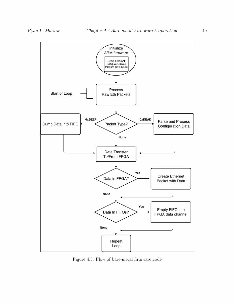
Ryan L. Marlow Chapter 4.2 Bare-metal Firmware Exploration 40
Figure 4.3: Flow of bare-metal firmware code

Ryan L. Marlow Chapter 4.2 Bare-metal Firmware Exploration 41
Figure 4.4: Raw Ethernet packet communication. 0xDEAD packets are used to configurethe target device.
Once the initialization sequence is complete, the firmware goes into an infinite while
loop. Inside the loop, the ARM listens for new Ethernet packets and data from the FPGA
that will be sent back to the host or another Ethernet connect FPGA platform. Raw Ether-
net packet communication is platform independent, since it is the same scheme as Virtex-5,
so a Virtex-5 and Zynq can be in the same network.
Raw Ethernet packets sent to the ARM contain configuration or data packets for the
FPGA, so those get processed in this loop. The 0xBEEF packet type contains I/Q data
meant to be processed by the FPGA. Data that are sent to the FPGA are first put into a
software FIFO. The entire content of the Ethernet packet is put into a FIFO. In a seperate
stage of the loop, if there is data in a designated data FIFO, then it is emptied into the
FPGA all at once. This process is the same for both input data channels from the ARM to
the FPGA.
The 0xDEAD packet type contains configuration data. Configuration data are processed
by the eth pkt process param function. A buffer holds the Ethernet packet payload
data. First, the parameter flags are fetched from the payload buffer. The flags are a byte of
one bit Booleans. These flags were already introduced and explained in Chapter 3, Section
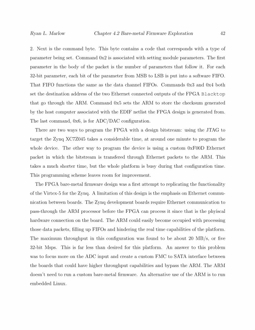
Ryan L. Marlow Chapter 4.2 Bare-metal Firmware Exploration 42
2. Next is the command byte. This byte contains a code that corresponds with a type of
parameter being set. Command 0x2 is associated with setting module parameters. The first
parameter in the body of the packet is the number of parameters that follow it. For each
32-bit parameter, each bit of the parameter from MSB to LSB is put into a software FIFO.
That FIFO functions the same as the data channel FIFOs. Commands 0x3 and 0x4 both
set the destination address of the two Ethernet connected outputs of the FPGA Blacktop
that go through the ARM. Command 0x5 sets the ARM to store the checksum generated
by the host computer associated with the EDIF netlist the FPGA design is generated from.
The last command, 0x6, is for ADC/DAC configuration.
There are two ways to program the FPGA with a design bitstream: using the JTAG to
target the Zynq XC7Z045 takes a considerable time, at around one minute to program the
whole device. The other way to program the device is using a custom 0xF00D Ethernet
packet in which the bitstream is transfered through Ethernet packets to the ARM. This
takes a much shorter time, but the whole platform is busy during that configuration time.
This programming scheme leaves room for improvement.
The FPGA bare-metal firmware design was a first attempt to replicating the functionality
of the Virtex-5 for the Zynq. A limitation of this design is the emphasis on Ethernet commu-
nication between boards. The Zynq development boards require Ethernet communication to
pass-through the ARM processor before the FPGA can process it since that is the phyiscal
hardware connection on the board. The ARM could easily become occupied with processing
those data packets, filling up FIFOs and hindering the real time capabilities of the platform.
The maximum throughput in this configuration was found to be about 20 MB/s, or five
32-bit Msps. This is far less than desired for this platform. An answer to this problem
was to focus more on the ADC input and create a custom FMC to SATA interface between
the boards that could have higher throughput capabilities and bypass the ARM. The ARM
doesn’t need to run a custom bare-metal firmware. An alternative use of the ARM is to run
embedded Linux.

Ryan L. Marlow Chapter 4.3 Embedded Linux 43
4.3 Embedded Linux
Embedded linux enables easier control over the platform. There are obvious implications
and improvements in a Linux based platform over embedded firmware. The user can more
easily customize the platform using a package manager or with their own software enabled
by the full Ubuntu Linux enviroment.
To program a bitstream with embedded linux, the file is converted into a binary file, which
is the reverse order of the generated bitstream. Xilinx provides a method for doing this, but
a custom script was created so there was less restrictions on the capability of the embedded
platform. Once generated, the binary file is piped to /dev/xdevcfg to actually configure
the reconfigurable device. By default, this reconfigures the whole device. In initial tests,
this was not a problem. In fact, programming through this method was significantly faster
than programming over JTAG. Eventually, when HDMI drivers were incorporated into the
FPGA static, programming the whole device interrupted that capability and hindered the
usability of the embedded Linux platform. sought to overcome this challenge.
Embedded Linux also gives a capability to install GReasy on the ARM. With both GReasy
enhanced GNU Radio and TFlow installed on the ARM, the FPGA/ARM can become a
fully capable SDR platform on its own, untethered from a host. This is further made capable
by the independence of vendor tools by using TFlow to generate the design bitstreams.
4.3.1 Embedded Linux Enabled Partial Reconfiguration
Programming a design for the Zynq XC7Z045 takes significantly more time than the Virtex-
5. Programming a Zynq takes about a minute, for full configuration. This minute hinders
the rapid prototyping characteristic that is desired in this project. A partial reconfiguration
like flow was developed to cut down on configuration time of the FPGA design to an order
of just a few seconds. This is possible by enabling partial reconfiguration on the Zynq device
and piping the binary file to /dev/xdevcfg.

Ryan L. Marlow Chapter 4.3 Embedded Linux 44
Figure 4.5: Partial Reconfiguration flow
Partial reconfiguration on the Zynq enables faster reconfiguration between designs. As
shown, in Figure 4.5, the board is programmed with an initital design consisting of the
static design and an empty Blacktop area. After generating a full bitstream with TFlow,
a partial bitstream is generated by calculating the difference between the intitial empty
Blacktop design and the new populated design. This partial bitstream is then used to
program the board to the target design. To program the board to a different design, a
partial bitstream is generated to configure the board back to the initial empty Blacktop
design. Once the board is empty, it can be reprogrammed with a different target design.
Alternatively, a ”hyperpath” can be used to generate a partial bitstream from two different
full designs.

Ryan L. Marlow Chapter 4.4 Embedded Linux 45
4.4 Zynq Enabled Use Models
Much like the software blocks found in GNU Radio, blocks in the FPGA hardware block
library are dragged and dropped to create a flowgraph radio design. This intuitive structure
for designs and integration into GNU Radio make GReasy easy to use for radio designers. A
number of different use models of GReasy are possible with the Zynq FPGA platform that
combines reconfigurable logic with an embedded ARM processor. In this section, these use
models will be examined.
4.4.1 Desktop Host Traditional GNU Radio
GReasy is modified GNU Radio with FPGA processing support. Traditional GNURadio
software processing is not disrupted by the modifications made in GReasy. Radio designers
already familiar with GNU Radio can still make flowgraphs that target software processing
blocks. The aim of GReasy is to augment the capabilities of GNU Radio without hindering it.
4.4.2 Desktop Host GReasy
The entry model of GReasy is to connect an augmented FPGA to a host desktop running
modified GNU Radio. Radio signal processing blocks that would normally be mapped to
software on the GNU Radio host can be replaced with higher throughput hardware blocks
on auxiliary FPGA hardware. The bitstreams are compiled on-the-fly in a matter of seconds
without disturbing the instant gratification characteristic of GNU Radio.

Ryan L. Marlow Chapter 4.4 Embedded Linux 46
4.4.3 Embedded Traditional GNU Radio
The low power utilization of the ARM core opens up many embedded and portable appli-
cations that are unrealizable with a traditional x86 machine. The ARM core also provides
the ability to run a full installation of GNU Radio in an efficient low power package. This
enables the use of flowgraphs that were developed on this unique platform as well as us-
ing GNU Radio Companion for interactive development right on the ARM. This opens the
possiblity to deploy a GReasy capable system on an embedded test platform in a variety of
enviroments in the field. GReasy is no longer limited by the need to be tethered to a desktop
host.
4.4.4 Embedded GReasy
Embedded GReasy combines the rapid reconfiguration of GReasy with the embedded benefits
of the ARM platform. Most radio designs have high speed sections that are parallel and
repetitive as well as low speed sections that are often more serial. Components that require
high throughput would not be efficient use of the embedded processor so they can be mapped
to the programmable logic. High speed components such as down mixers and FIR filters
perform well on programmable logic, while many low speed tasks such as protocol parsing
are best performed on a general purpose processor. Embedded GReasy makes it possible to
assign these tasks to their most efficient target all on a single chip.
4.4.5 Multiple Models and Devices
A radio designer can easily target multiple use cases in the same flowgraph. Using the
GReasy desktop, Zynq boards can be clustered together and desktop software components
can be mixed with embedded software components on the Zynq’s ARM as well as hardware

Ryan L. Marlow Chapter 4.4 Embedded Linux 47
Figure 4.6: Multiple uses and models can be targeted in a single flowgraph.
components on the Zynq programmable logic. Alternatively, while targetting an embedded
GReasy flow on a Zynq ARM, ARM software processing blocks and hardware processing
blocks can both be used together. An embedded GReasy flow can also interact with the
GReasy desktop flow. Multiple of these boards can interact with one another as well, either
through the Ethernet communication on the ARMs or the SATA communication through the
hardware. Two users could even create interacting flowgraphs between different platforms,
with two desktops controlling different nodes in the cluster or an embedded platform node
interacting with a desktop controlled portion of the cluster.

Chapter 5
Merging with GNU Radio 3.7
It’s important to keep GReasy relevant and up to date in the current tools that are out there
in the open-source community. When work on GReasy first began, it targeted GNU Radio
3.3. That is now years old and GNU Radio is at Version 3.7, with a plethora of improve-
ments. The jump simply from 3.6 to 3.7 was significant and has been a well known milestone
within the GNU Radio community. It made sense to update GReasy up to this version. This
section will detail the differences between Versions 3.3 and 3.7 as well as the new features
and technology introduced in the new version. In this section, GReasy’s integration into the
new GNU Radio 3.7 will be explained such as challenges and solutions that were found in
this integration process.
The differences between GNU Radio Versions 3.3 and 3.7 are numerous. The overall
structure of the source files and directories is entirely different. A large portion of the block
library was rearranged into a more flattened and organized structure. Different tools are
used to build GNU Radio. New utility tools make creating modules easier and streamlined.
Significant and new features include ControlPort, new QTGUI enhancements, and new
performance measurement tools for software processing blocks. ControlPort is a new
interface for standardizing remote procedure calls.
48
Ryan L. Marlow Chapter 5.1 Updated File/Directory Structure 49
5.1 Updated File/Directory Structure
The overall structure of the GNU Radio source has been changed significantly in release,
3.7. Therefore, GReasy should also follow suit and accommodate to these code changes by
integrating into the new code structure while maintaining the same functionality as in GNU
Radio 3.3.
GReasy built on GNU Radio 3.3 used a number of ”hooks” in the run-time code to gen-
erate flowgraph information needed to generate an EDIF netlist of the hardware design.
The process of generating this EDIF has already been explained in Chapter 3, Section 1.
The structure of the GNU Radio run-time code was flattened in the transition to 3.7. The
run-time code used to be a sub-directory in the gnuradio-core directory, which also
contained the core C++ block library and utility functions that could be used to analyze
the data in Octave or Matlab. In 3.7, the gnuradio-core directory was split based on
different purposes to flatten the structure of the source code. The run-time code is now
located in gnuradio-runtime in its own directory at the top of the GNU Radio source.
Each directory at the top of the GNU Radio source then contains subdirectories: apps,
examples, include, lib, python, and swig. These are mostly self-explanatory.
Header files that include support functions and classes are located in the include directory.
The lib directory contains the bulk of the C++ code. The swig directory contains the
special SWIG scripts that generate the Python wrappers to interface and use C++ with
Python code. The python directory contains Python code that calls the SWIG wrapper
functions that interface with C++. Block library based directories, such as gr-blocks or
gr-afpga (GReasy’s FPGA based block library), also contain a sub-directory grc that
contains the XML representations of blocks used by the graphical GNU Radio Companion.
GNU Radio and GReasy run-time code is contained in gnuradio-runtime/lib. As
in GNU Radio 3.3, connections between modules in the flowgraph are written to a file in
the function connect in the file flowgraph.cc. If a connection between blocks made by
the GNU Radio user contains a block at the start or end of the connection from the afpga

Ryan L. Marlow Chapter 5.1 Updated File/Directory Structure 50
Figure 5.1: File structure of GNU Radio 3.7 with GReasy additions.
block library, then that connection is written to the fpga connection.txt file temporar-
ily stored in /tmp. This file is used to store this information that is used later in the custom
EDIF generation code given in Chapter 3, Section 1. This code is executed from the start
function in top block imp.cc. The start function is the code that literally starts the
execution of the flowgraph functions. The GReasy run-time code occurs as a final step before
flowgraph blocks start data processing.
In addition to improving the EDIF construction algorithm, the GReasy run-time code
was reorganized to be better integrated into GNU Radio, in an effort to plan for the future
of GReasy as a potential release received by the open-source community. GReasy run-time
code is in the subdirectory greasy in the lib directory of gnuradio-runtime. The main
connect edif function that generates the EDIF netlist is in gr easy edif connector.cc.
This is the function called by top block impl.cc function start.
The connect edif function calls code from other source files in that greasy sub-
Ryan L. Marlow Chapter 5.1 Updated File/Directory Structure 51
directory. Gr easy edif data.cc and .h contain declarations and definitions of the
Entry classes, which are data structures that store EDIF netlist data. Examples of these
are the module representations given as Cell Entry objects and connections between
modules given as Loop Entry objects. These Entry classes are defined in more detail
in Chapter 3, Section 1. The legacy Ethernet packet communication code to configure
the device before data processing is found in this directory as well. These are located
in gr easy packet creator.h and gr easy raw ethernet.h. This configuration
scheme is used by the Virtex-5 and bare-metal firmware Zynq platforms.
Much like GReasy based on GNU Radio 3.3, the GNU Radio library of FPGA processing
blocks are located in the directory gr-afpga located in the GNU Radio source top. The
legacy communication based on the legacy USRP data transfer during run time, written by
Charles Irick [2] has been ported to be incorporated into this directory. This data transfer
and communication is used by the Virtex-5 and bare-metal firmware Zynq platforms. This
data handling code was one of the more difficult code transitions because it included some
dependencies of GNU Radio code that has been either reorganized or outright eliminated,
these dependencies being gruel, omnithread and some extra math functions originally defined
in the gnuradio-core directory that are now in gnuradio-runtime.
The gr-afpga directory was generated using the gr modtools utility as an out-of-tree-
module library, the process of which will be further explained in this Chapter, Section 3.
Much like an in-tree-module library in the vanilla GNU Radio 3.7, the gr-afpga library
contains the same standard subdirectories with the same code organization. The GReasy
afpga block library is compiled separately from the main GNU Radio source as explained in
the next section.
Finally, the customized Variable blocks used in FPGA parameter configuration are mostly
unchanged. The directory in the GNU Radio top source that contains these Variable blocks
is gr-wxgui. This directory contain blocks based on the wxgui library in Python, which in
turn is based on the wxPython library. The wx-gui library has the standard subdirectories.
The customized code is placed in the Python subdirectory, altering the converters.py,

Ryan L. Marlow Chapter 5.2 Build Tools 52
forms.py and includes the custom file parameters.py. These alterations handle the
parameter configuration communication needed to configure parameters while the GNU Ra-
dio flowgraph, and more importantly the auxiliary FPGA(s) are processing data.
5.2 Build Tools
GNU Radio 3.3 is built using automake [29]. Automake is a tool for generating makefiles
from Makefile.am files. In the extended GNU Radio 3.3 that was GReasy, out-of-tree
modules in the gr-afpga block library were built using the same automake tools as the
rest of GNU Radio.
GNU Radio 3.6 and 3.7 are built using CMake [30]. CMake is a cross platform build
system that is used in conjunction with native build tools. CMake command files labeled
CMakeLists.txt are located in every directory in a project with commands and mes-
sages. CMake can generate a native build environment that will compile source code, create
libraries, generate wrappers and build executables in arbitrary combinations. CMake is
designed to support complex directory hierarchies and applications dependent on several
libraries, which happens to be the case for GNU Radio.
The new build process using the CMake build system requires the user to build the GNU
Radio top and the gr-afpga module library separately since gr-afpga is an out-of-tree
module. This makes it easier and faster to make changes or add additional components to
the gr-afpga library without having to recompile the entire GNU Radio source. GNU
Radio now comes with its own build script called build-gnuradio that works for Fedora
or Ubuntu systems, but still requires the user build the gr-afpga module library or other
separately. If the user desires to do it manually, there’s a straightforward process to do so.
CMake compiles source into its own build directory separate from the source being compiled
in an effort to keep the source directories less cluttered. The initial build of GNU Radio
requires the user to make the build directory. Then, after navigating into the new build

Ryan L. Marlow Chapter 5.3 Module Registration 53
directory the user inputs the command cmake ../ to populate the build directory with
the CMake scripts in the GNU Radio source. Still in the build directory, all that’s left is
running make. These same steps are used to build the out-of-tree modules individually with
their own build directory such as gr-afpga.
5.3 Module Registration
There is a predefined process for creating a FPGA processing module and registering it with
GReasy. To register a component, first the user needs to implement the hardware design
using traditional vendor tools such as Xilinx ISE or Vivado. After the user has created their
hardware design, the source of that design is compiled and registered into the TFlow module
library. That registration process generates metadata including an EDIF netlist of the top
module. That EDIF netlist is placed into the GNU Radio afpga module library under
the subdirectory gr-afpga. This EDIF is used to generate information later used when
connecting modules together in the flowgraph.
GNU Radio 3.7 introduced a new utility tool called gr modtool used to assist in the
creation of out-of-tree modules and module libraries. In the creation of a module, a portion
of the required code is just boilerplate code and Makefile editing as defined by the GNU
Radio Blocks Coding Guide [31]. gr modtool aims to reduce this monotony of creating a
new module by automating much of this process. On it’s own, gr modtool generates the
boilerplate code in the include, lib, swig, and grc directories. If the user wants to
generate testing code, those boilerplate components can be generated as well. The include
and lib directories contain the core C++ code of the GNU Radio block and swig directory
contains the SWIG script to generate the Python interfaces to the C++ code. The code
generation is aided by the Python powered template engine and code generator, Cheetah
[32].
GReasy based on GNU Radio 3.3 had its own module creation script that read in the

Ryan L. Marlow Chapter 5.3 Module Registration 54
module EDIF to extract information about the module and use that in the module creation
process. By combining efforts from the previous GReasy module registration script called
register and building a customized script around the gr modtool, GReasy in GNU
Radio 3.7 has gr easy modtool located in the gr-afpga library directory.
The gr easy modtool script reads in user defined command line arguments. The user
can define the target EDIF to be read in by the script, and therefore the module being
created. The device family, whether Virtex-5, Zynq, or Kintex can be defined. The names
of the reset and clock lines are defined, but defaulted to rst and clk based on the GReasy
module creation standards [33]. If the module has parameters, the user defines those pa-
rameters in this module registration script first by inputting the number of parameters as a
command line argument and then defining the names and default values of those parameters
later if that flag is set. After reading in the command line arguments, the first thing the
custom modtool script does is run gr modtool to generate the boilerplate base code for
the desired module.
The gr modtool script uses Cheetah to generate the C++ boilerplate code. A custom
Cheetah template was created for modules in the gr-afpga block library. The standard
and customized Cheetah template source can be found in the file templates.py in the
source for gr modtool located in the gr-utils directory at the GNU Radio source top.
This template is targeted by running gr modtool with the option of generating an afpga
type module.
Once gr modtool has generated those bits of code, gr easy modtool proceeds with
the steps similar to the previous GReasy registration script found in GNU Radio 3.3. The
EDIF for the module is searched for input and output port information. This information
is used by the C++ constructor to generate data used in the flowgraph construction phase
when the user executes the flowgraph containing FPGA processing blocks. This is also used
in generating an XML representation of of the block. The XML representation needs an
accurate depiction of the input and output data ports so the use can connect other modules
or data sources and sinks to it correctly. A known bug of gr modtool is the improper

Ryan L. Marlow Chapter 5.3 Module Registration 55
generation of XML, so we replace that with our own XML generated by gr easy modtool
with the metadata derived from the module EDIF.

Chapter 6
Implementations and Results
This chapter provides an overview of the implementations of this work with real hardware
and real radio designs based on these tools. Using GReasy, a radio designer, who is a non-
expert in hardware design, can create radios targetting reconfigurable hardware. The goal
here is to prove that these tools have a real-world application, enable rapid compilation of
hardware to non-experts, and could be useful outside of just a research toy.
6.1 Demo Platforms
Through the iterations of this work, there were a number of hardware platforms made to
demonstrate the GReasy/TFlow enabled Zynq device.
When first developing the Zynq support infrastructure, a Zynq board was attached to
the legacy Virtex-5 Demo platform as an additional FPGA in the cluster. Data could be
transferred via Ethernet to and from the Virtex-5 FPGAs, the newly added Zynq board,
and the GNU Radio host. Real radio data could be collected by the old platform’s high
speed ADC and transferred to the Zynq through a Virtex-5. This was a primitive platform
meant only for initial testing but was an important first step in the process of creating
56

Ryan L. Marlow Chapter 6.1 Demo Platforms 57
Figure 6.1: Demo Platform Block Diagram. Mouser, ”AD-FMCOMMS1-EBZ” [On-line]. Available: http://www.mouser.com/images/adi/images/AD-FMCOMMS1-EBZ.jpg. Used under fair use, 2014. Silica, ”Silica Xilinx Zynq 7000 SoC ZC706Eval Kit icon” [Online]. Available: http://www.silica.com/fileadmin/02 Products/Productdetails/Xilinx/Silica Xilinx -Zynq-7000-SoC-ZC706-Eval-Kit-icon.jpg,
Used under fair use, 2014. Zedboard, Z̈edBoard RevA[̈Online]. Available:http://www.zedboard.org/sites/default/files/product spec images/ZedBoard Rev A sideA0 0(1) 0.jpg. Used under fair use, 2014. Photo by Kevin Lee. Used under fair use, 2014.
Zynq capable platform. This initial test demonstrated that multiple hardware platforms, of
different hardware families could be connected in a GReasy flowgraph and perform signal
processing applications cooperatively.
The next platform iteration was the main platform used to demo the project. This platform
includes an ADC front-end, an expandable number of Zynq FPGA development boards, and
a custom 3-D LED visualization cube. This set up is shown in Figure 6.1. The ADC is
attached via FMC to the Zynq XC7Z045 dev board, while the additional Zynq boards are
connected to the XC7Z045 via FMC-to-SATA connectors to enable higher speed data transfer
than the Ethernet through ARM. Radio data is received from the ADC radio card and that
data is preprocessed to reduce, decimate, or split the data in some way on the Zynq XC7Z045
front end. Then the remaining Zynq ZED Boards can perform additional processing on the
data before transferring the output through the DMA interface to the ARM, which is running
software that commands the visualization cube through raw Ethernet packets.

Ryan L. Marlow Chapter 6.1 Demo Platforms 58
Figure 6.2: ADC Block Diagram
6.1.1 ADC/DAC Capabilities
The AD-FMCOMMS1-EBZ from Analog Devices is a high-speed analog module that pro-
vides GReasy with a radio front-end and connects to the Zynq test platform over the FMC
LPC port, which then connects to the FPGA static [34]. The FMCOMMS1-EBZ radio card
enables a variety of wireless communications functions at the physical layer, from baseband
to RF. This RF module is software tunable, from the Zynq ARM, across a wide frequency
range (400MHz to 4GHz) with 125MHz of channel bandwidth (250MSPS ADC, 1GSPS
DAC). Figure 6.2 shows the block diagram of the reference design from Analog Devices that
provides a hardware interface for the FMCOMMS1-EBZ radio front-end.
In the Analog Devices reference design, the data are transferred between the processor
memory and the RF module using a DMA engine. This approach is satisfactory for software-
only processing in the ARM but introduces performance bottleneck (CPU-in-the-middle).
The GReasy Zynq-based FPGA static uses this reference design only to provide an initial
configuration to the RF module. After the radio parameters are initialized, the reference
design is replaced with a pruned-down light-weight version that provides a direct interface

Ryan L. Marlow Chapter 6.1 Demo Platforms 59
Figure 6.3: Cognitive Radio Test Bed. The stack of XC7Z020’s are fully connected to oneanother through the FMC to SATA interfaces. Photo by Ryan Marlow, 2014.
between the FMC card and the GReasy design in the FPGA sandbox. The current FPGA
static supports data acquisition directly from the RX path, without ARM intervention.
6.1.2 Cognitive Radio Platform
It’s worth mentioning that an additional hardware platform was made using five Zynq based
FPGA boards. This platform was developed as a cognitive radio test-bed. Without going
into the specific details of other students’ thesis work, a brief explanation of an application
will be given but more can be found in each of their theses [35] [36]. The platform uses a
Zedboard with a Zynq FPGA as a controller of the other four boards, XC7Z020 developement
boards. Each board runs an embedded GReasy flowgraph with FPGA capabilities targeting
the reconfigurable fabric of itself.
A radio data file can be loaded onto the platform’s controlling board, a Zedboard. As an
example, the controlling board could have an FFT or some other signal analyzing application.

Ryan L. Marlow Chapter 6.2 GReasy Hardware Modules 60
Based on the output of the radio data analysis, the controller board can decide to reprogram
the other boards with radio processing applications such as changing the receiving tuner
frequency, applying some filtering to the signal, or modifying the modulation scheme.
6.2 GReasy Hardware Modules
In order to test and verify the new Zynq platform, a number of radio designs were created
along with some non-radio designs used to demonstrate the capabilities of the platform. This
section will detail the concepts and implementations of these designs.
6.2.1 BPSK Demod Design
This design is composed of three GReasy hardware modules, each represented as separate
FPGA block in the GNU Radio flowgraph. The first block is a decimator, which decimates
the signal by 16. The next block is the main BPSK demodulator, which converts the input
radio signal into a stream of binary based on the phase of the signal. The final block is a
data recovery block, which converts that stream of binary into ASCII characters by locating
a header value and then building bytes of data after that known header value. This design
was derived from the Virtex-5, but was never fully functional on the Zynq device. It was
still used as a test for resource constraints and the run-time assembly phase of TFlow.
6.2.2 Zigbee
A reliable way to verify the new platform is to transfer known working designs from legacy
hardware to the new platform. A Zigbee receiver module was first used to demonstrate the
radio processing capabilities of the Virtex-5 based GReasy platform [3].
An important aspect of a radio design is its processing of the radio signal in real time.

Ryan L. Marlow Chapter 6.2 GReasy Hardware Modules 61
Therefore, it was important to replicate the environment of the old system as much as possi-
ble. The previous Virtex-5 Blacktop ran at a clock rate of 60MHz. The Zynq Blacktop
design derives its clock from the ADC, which has set values to the clock rate that are possi-
ble. The closest clock rate the platform can get to 60MHz is 61.44MHz. The Zigbee receiver
needed to be modified with a hesitator signal to compensate for the difference. In addition,
it was given that a phase detection submodule was expecting a change in phase in the mod-
ulation scheme after five samples of data. This was determined to be wrong and changed to
30 samples based on debugging experiments with the Xilinx debug utility, Chipscope [37].
Radio data is received through the ADC at 2.41 GHz carrier frequency, as specified by the
Zigbee specifications [38]. The ADC downsamples the signal to 61.44MHz, which is also
the clock rate driving the Blacktop design, which includes the Zigbee receiver hardware
module. The output of that module is demodulated data from the Zigbee signal that can
then go through a ”data recovery” stage with an additional hardware module, or the data
can be transferred to software for that step before it is dumped to a text file or used to drive
the visualization cube.
6.2.3 Tuner
A module that benefits from parameterization is the frequency tuner module. Prior to cus-
tom parameter modules, every different value of tuning would require a new hardware block
in the module library even though the difference between modules would be a simple value
change. Module parameter configuration minimizes the waste of repeated library compo-
nents by combining modules with similar functionality where simple value configurations
can alter the module functionality. The tuner module contains two parameters that can be
configured during flowgraph run-time, which are a value from 0-.5 and a direction: positive
or negative. The tuner block uses these values to tune the frequency from -50% to 50% from
the baseband frequency value.

Ryan L. Marlow Chapter 6.2 GReasy Hardware Modules 62
6.2.4 DES Encryption
As another use case for parameter configuration, DES encryption and decryption modules
were implemented and added to the TFlow library. Each encryption/decryption module has
two 32-bit parameters associated with it, each making up a 64-bit key. Each 64 bit key is
operated on to generate 48-bit sub-keys for different steps of shifting in encryption. Despite
that the encryption keys are sent in plaintext in the parameter configuration stage, the na-
ture of DES makes that knowledge almost useless without reverse engineering the exact shift
ciphering and sub-key generation algorithms used by the module.
DES encryption is a good match for FPGAs because of the ciphers that are used to en-
crypt data can be parallel processes. Streaming data through DES involves many stages of
shifting and ciphering the input message. Much of the calculation and ciphering performed
in DES can be done with simple logic or arithmetic operations. Other than using a BRAM
to hold generated sub-keys, the rest of the algorithm is built with the FPGA configurable
logic blocks.
6.2.5 Cube Experiments
As a means of displaying the capabilities of TFlow and GReasy in a flashy and fun way, a 3-D
LED cube was incorporated into the demo platform. The cube is made up of 512 full RGB
LED lights. Each LED can be individually programmed or one can use an established Python
API for easy display of patterns or symbols on the cube. Some special demonstrations were
made that used the cube while also highlighting GReasy and TFlow. As an example, the
Zigbee receiver was used to receive a message and print that message on the cube. Other
cube explorations include 2-D and 3-D versions of the game of life and various ”animations”.
These explorations were used as demonstrations of TFlow’s independence of GReasy. The
cube is shown in Figure 6.4.

Ryan L. Marlow Chapter 6.3 Results 63
Figure 6.4: The Cube: Demo visualizer. In this image, showing randomized colors. Photoby Ryan Marlow, 2014
6.3 Results
Tests were performed to gather data on bitstream compilation time of the desktop and em-
bedded GReasy using TFlow as well as resource utilization of precompiled modules in TFlow.
The desktop environment targeted the Zynq-7000 SoC ZC706 FPGA development board,
while the embedded environment was run on a ZedBoard equipped with a Zynq-7000 ZC702
chip on the Zedboard. The desktop program was run in Ubuntu 13.04 64-bitwidth GNU
Radio 3.3. The host computer is equipped with an Intel Core i7-2600 CPU @ 3.40GHz x 8
CPU and 7.8 GB of RAM. The ZedBoard has a Cortex-A9 ARM @ 866MHz x 2 CPU and
1 GB of RAM with Linaro Ubuntu 13.09 32-bit with GNU Radio 3.7.
In the first phase of TFlow design, modules are precompiled and added to the TFlow
module library while representations of the modules are registered to GNURadio as well. In
the precompilation phase, modules are placed and shaped into rectangular regions on the
FPGA fabric. They are currently constrained to being placed around clock region coordi-
nates, so there are some resources wasted in the process. Table 6.1 shows example designs
and resource allocations when shaped and mapped for TFlow placement compared to the

Ryan L. Marlow Chapter 6.3 Results 64
Table 6.1: Resource Usage of Precompiled Modules
Modules CLB BRAM DSP
Decimate By 16 Allocated 200 0 20Required 168 0 4
BPSK Demod Allocated 350 10 20Required 302 3 7
Data Recovery Allocated 50 0 0Required 24 0 0
Full BPSK Design Allocated 600 10 40Required 494 3 10
Frequency Tuner Allocated 100 5 20Required 50 2 3
DES Encryption Allocated 500 10 0Required 495 1 0
Zigbee Receiver Allocated 300 0 10Required 281 0 10
required resources when compiled with the vendor tools.
The speed up in bitstream generation with TFlow is considerable. The next few tables,
6.2-6.5 provide comparisons between vendor tools and different variations of TFlow. Table
6.2 gives the compilation time in seconds to generate a bitstream for four SDR designs. Ta-
ble 6.2 compilation time includes the entire static design as well as the hardware processing
modules as that is the design that is being fully assembled by TFlow in the design assembly
phase.
A step in the TFlow compilation process is reading in XML files, which can take a consid-
erable amount oNew f time. It was determined that by converting these XML files to binary
files instead, the time to read in and process the data in those files drops significantly. Table
6.3 and 6.4 provide the results that demonstrate that improvement. The current version of
GReasy uses this binary conversion because, as the tables show, much time is saved with this
change. Regardless of file conversion or not, there is significant time saved by using TFlow
over traditional vendor tools to generate a bitstream. By incorporating TFlow into GNU
Radio and using it as the backbone of GReasy, rapid bitstream assembly is enabled. Using

Ryan L. Marlow Chapter 6.3 Results 65
Table 6.2: Assembly Time Using Traditional Vendor Tools
Design seconds
Full BPSK Design 1184Frequency Tuner 1015DES Encryption 1122Zigbee Receiver 1106
Table 6.3: Assembly Time with GReasy Desktop without binary conversion
Design seconds
Full BPSK Demod 22Frequency Tuner 17DES Encryption 18Zigbee Receiver 21
FPGAs in the loop of GNU Radio does not significantly hinder the minimal turn-around
times expected from the rapid prototyping platform.
While the gains in TFlow are significant, these tables might not be providing the entire
story. These tables show the times to generate a bitstream from precompiled components.
The static design region and the modules placed in the Blacktop design region require
time for precompilation. This varies depending on the size of those designs, but are done
with traditional vendor tools. The times to generate a static design are similar to the times
given in Table 6.2. The difference here is that, much like the name implies, the static region
can remain static between designs. The idea is the user has some determined pre/post pro-
Table 6.4: Assembly Time with GReasy Desktop
Design seconds
Full BPSK Demod 8.5Frequency Tuner 6.5DES Encryption 8.7Zigbee Receiver 7.4

Ryan L. Marlow Chapter 6.3 Results 66
Table 6.5: GReasy Modules Precompilation Time
Design seconds
Decimate By 16 480.3BPSK Demod 490.5Data Recovery 502.1Frequency Tuner 461.7DES Encryption 523.2Zigbee Receiver 455.9
cessing that will be performed in every design, so the static only needs to be generated once.
Modules placed in the Blacktop too only need to be generated once. Table 6.5 gives com-
pilation times of pregenerating the components used in the test designs in the other tables.
Much like the static generation, this precompilation of modules only needs to happen once,
or each time a module needs to be changed.
Times for design assembly on the embedded GReasy platform are in Table 6.6. There is
some lost performance from running TFlow on an embedded platform, but that does not
outweigh the benefit of compiling full hardware designs on an embedded platform. These
times are running the entire GReasy flow on Zynq’s embedded ARM.
Typical designs with a manageable number of hardware modules have very little prob-
lem being completely placed on the FPGA and therefore have a nearly constant bitstream
generation time in TFlow. That time is increased when resources on the FPGA become
limited but these problems can be averted with a larger FPGA or switching the design to
target multiple devices. When using FPGA acceleration, there is an additional overhead,
regardless of bitstream generation tool; programming time. But, with the unique Partial
Reconfiguration like flow on the embedded Linux Zynq platform, the programming time is
cut down to just a few seconds of configuration.
After programming, static and module parameter configuration takes, at most, less than a
second. On the bare-metal firmware Zynq, configuration takes about a millisecond from the
time the configuration packet is sent to receiving an acknowledge packet when configuring a
single module. That time linearly increases when more modules are added to the configura-

Ryan L. Marlow Chapter 6.3 Results 67
Table 6.6: Assembly Time with GReasy Embedded
Design seconds
Full BPSK Demod 60.9Frequency Tuner 50.7DES Encryption 52.5Zigbee Reciever 50.4
tion chain, with about a millisecond per module. This process occurs for each configuration
type, i.e., module parameters, design checksum, device output destination. A single Eth-
ernet packet is used to configure all library module parameters on a device with virtually
no limitation. Unfortunately, a limitation of switching to embedded Linux is the current
method for configuring module parameters is a bit slower. Using ssh to run software on
the ARM provides an easy way to change functionality but at the cost of conferring a slight
overhead of communication.
Finally, Table 6.6 demonstrates assembly time on the GReasy embedded platform. Since
the embedded ARM is not as powerful as the desktop computer used in the GReasy host
experiments, its performance was expected to be expectantly less.

Chapter 7
Conclusion
This work has demonstrated the feasibility and usability of an FPGA based SDR integrated
with GNU Radio in GReasy. The transition to the Zynq hardware opens new capabilities
for the GReasy framework. Code updates have enabled multiple FPGA families the ability
to interact and create heterogeneous radio architectures with a host or embedded CPU.
This work introduced the concept of an all in one embedded platform on the Zynq by
incorporating an Embedded GNU Radio with the Zynq. The enhancements made to GNU
Radio with FPGAs in addition to bitstream generation tools like TFlow enable broader us-
ability. A core implication of GReasy is enabling users with limited knowledge of HDL design
to create designs that utilize the broader processing capabilities of reconfigurable hardware.
With GReasy, a larger class of SDR can be realized while preserving the instant gratification
achieved in GNU Radio through rapid prototyping.
68

Ryan L. Marlow Chapter 7 Conclusion 69
7.1 Future Work
There are still limitations to the processing module components, such as a limited library.
There still are some basic filtering blocks that are absent and many other functions that
could benefit from hardware acceleration. As the library size increases, there needs to be
a better way for TFlow to organize library components than just a simple file structure.
This same problem may also exist in the GNU Radio, GReasy front end experience as well.
As capabilities increase, having modules organized simply by FPGA family may eventually
become too cumbersome. Perhaps having different types of functions organized into different
library types. Example: Virtex-5 filters, Zynq Sample Rate Converters, etc.
A new platform, Kintex-7, specifically the USRP X310 will be the subject of future
work [39]. This USRP platform can be the target to offer GReasy to a wider audience
since the Ettus USRP is an established SDR hardware platform that can benefit from rapid
reconfiguration through GReasy. It is through this work that GReasy or some aspects thereof
could be released back to the open source community.

Bibliography
[1] E. Blossom. GNU Radio, 2013. http://gnuradio.org.
[2] C. Irick. Enhancing GNU Radio for Hardware Accelerated Radio Design. Master’s
thesis, Virginia Polytechnic Institute and State University, Blacksburg, VA, 2010.
[3] R. Stroop. Enhancing GNU Radio for Run-Time Assembly of FPGA-Based Accelera-
tors. Master’s thesis, Virginia Polytechnic Institute and State University, Blacksburg,
VA, 2012.
[4] Walid A Najjar, Wim Bohm, Bruce A Draper, Jeff Hammes, Robert Rinker, J Ross
Beveridge, Monica Chawathe, and Charles Ross. High-level Language Abstraction For
Reconfigurable Computing. Computer, 36(8):63–69, 2003.
[5] A. Love, Wenwei Zha, and P. Athanas. In pursuit of instant gratification for fpga
design. In Field Programmable Logic and Applications (FPL), 2013 23rd International
Conference on, pages 1–8, Sept 2013.
[6] Zynq-7000 All Programmable SoC Overview DS190 (v1.2).
[7] R. Marlow and P Athanas. An Enhanced and Embedded FPGA GNU Radio Flow. In
Wireless Innovation Forum SDR-WinnComm 2014, pages 146–153, 2014.
[8] MicroBlaze Processor Reference Guide.
70

Ryan L. Marlow Bibliography 71
[9] Zynq-7000 SoC Operating Systems, 2014. http://www.xilinx.com/products/silicon-
devices/soc/zynq-7000/operating-systems/index.htm.
[10] B. E. Nelson, M. J. Wirthlin, B. L. Hutchings, P. M. Athanas, and S. Bohner. Design
Productivity for Configurable Computing, ERSA 08: Proceedings of the International
Conference on Engineering of Reconfigurable Systems and Algorithms. pages 57–66,
2008.
[11] D. Dye. Partial Reconfiguration of Xilinx FPGAs Using ISE Design Suite. White Paper,
2012.
[12] C. Kohn. Partial Reconfiguration of a Hardware Accelerator on Zynq-7000 All Pro-
grammable SoC Devices. White Paper, 2013.
[13] Chandra Mulpuri and Scott Hauck. Runtime and Quality Tradeoffs in FPGA Placement
and Routing. In Proceedings of the 2001 ACM/SIGDA Ninth International Symposium
on Field Programmable Gate Arrays, FPGA ’01, pages 29–36, New York, NY, USA,
2001. ACM.
[14] F. Vahid, G. Stitt, and R. Lysecky. Warp Processing: Dynamic Translation of Binaries
to FPGA Circuits. Computer, 41(7):40–46, July 2008.
[15] C. Lavin, M. Padilla, J. Lamprecht, P. Lundrigan, B. Nelson, and B. Hutchings. lav-
inhmflow: Accelerating fpga compilation with hard macros for rapid prototyping. In
Field-Programmable Custom Computing Machines (FCCM), 2011 IEEE 19th Annual
International Symposium on, pages 117–124, May 2011.
[16] T. Frangieh. A Design Assembly Technique for FPGA Back-End Acceleration. PhD
thesis, Virginia Polytechnic Institute and State University, Blacksburg, VA, 2012.
[17] N. Steiner. Tools for Open Reconfigurable Computing, 2014. http://torc-
isi.sourceforge.net/index.php.

Ryan L. Marlow Bibliography 72
[18] III Mitola, J. Software Radios: Survey, Critical Evaluation and Future Directions.
Aerospace and Electronic Systems Magazine, IEEE, 8(4):25–36, April 1993.
[19] Jeffrey Hugh Reed. Software Radio: A Modern Approach to Radio Engineering. Upper
Saddle River, N.J. : Prentice Hall, 2002.
[20] J. Blum. GNU Radio-GNURadio Companion, 2013.
http://gnuradio.org/redmine/projects/gnuradio/wiki/GNURadioCompanion.
[21] SWIG - Executive Summary, 2014. http://www.swig.org/exec.html.
[22] G.J. Minden, J.B. Evans, L. Searl, D. DePardo, V.R. Petty, R. Rajbanshi, T. Newman,
Q. Chen, F. Weidling, J. Guffey, D. Datla, B. Barker, M. Peck, B. Cordill, A.M. Wyglin-
ski, and A. Agah. KUAR: A Flexible Software-Defined Radio Development Platform. In
New Frontiers in Dynamic Spectrum Access Networks, 2007. DySPAN 2007. 2nd IEEE
International Symposium on, pages 428–439, April 2007.
[23] G. Inggs, D. Thomas, and S. Winberg. Building a Rhino Harness A Software Defined
Radio Toolflow for Rapid Prototyping Upon FPGAs. In Industrial Technology (ICIT),
2013 IEEE International Conference on, pages 1098–1103, Feb 2013.
[24] W. Plishker, G.F. Zaki, S.S. Bhattacharyya, C. Clancy, and J. Kuykendall. Applying
Graphics Processor Acceleration in a Software Defined Radio Prototyping Environment.
In Rapid System Prototyping (RSP), 2011 22nd IEEE International Symposium on,
pages 67–73, May 2011.
[25] Virtex-5 Famly Overview. http://www.xilinx.com/support/documentation/data sheets/
ds100.pdf.
[26] J. Corgan. USRP Intro, 2013. http://gnuradio.org/redmine/projects/gnuradio/wiki/Usrp
FAQIntro.
Ryan L. Marlow Bibliography 73
[27] R. Stroop and P. Athanas. Enhancing GNU Radio For Run-time Assembly of FPGA-
Based Accelerators. In Wireless Innovation Forum SDR-WinnComm 2013, pages 87–95,
2013.
[28] J. I. ; Bennett Hillawi and K. R. EDIF - An Overview. Computer- Aided Engineering
Journal, 3(3):102–107, June 1986.
[29] automake, 2014. http://www.gnu.org/software/automake/manual/html node/index.html.
[30] CMake - Cross Platform Make, 2014. http://www.cmake.org/.
[31] BlocksCodingGuide - GNU Radio, 2014. http://gnuradio.org/redmine/projects/gnuradio/
wiki/BlocksCodingGuide.
[32] Tavis Rudd. Cheetah - The Python Powered Template Engine, 2014.
http://www.cheetahtemplate.org/.
[33] How To Create A GReasy Block in GNU Radio 3.7. 2014.
[34] Various. AD-FMCOMMS1-EBZ Functional Overview [Analog Devices
Wiki], 2014. http://wiki.analog.com/resources/eval/user-guides/ad-fmcomms1-
ebz/hardware/functional overview.
[35] K. Rooks. A Zynq-base Cluster Cognitive Radio. Master’s thesis, Virginia Polytechnic
Institute and State University, Blacksburg, VA, 2014.
[36] C. Dobson. An Architecture Study on a Xilinx Zynq Cluster with Software Defined
Radio Applications. Master’s thesis, Virginia Polytechnic Institute and State University,
Blacksburg, VA, 2014.
[37] ChipScope Pro Software and Cores User Guide, 2006.
http://www.xilinx.com/ise/verification/chipscope pro sw cores 8 2i ug029.pdf.
[38] Zigbee Wireless Standard - Technology - Digi International, 2014.
http://www.digi.com/technology/rf-articles/wireless-zigbee.

Ryan L. Marlow Bibliography 74
[39] Product Detail, 2014. https://www.ettus.com/product/details/X310-KIT.

Appendix A
Program Source
A.1 GNU Radio Runtime Code
These code snippets are referenced in the text. A lot more code contributions were written
towards this thesis but would not be very useful to just copy + paste code into this document.
This section serves as an overview to the referenced code. Additional code contributions can
be retrieved on the GReasy svn repository. The url of the repository is:
http://www.ccm.ece.vt.edu:8444/usvn/svn/GReasy
A.1.1 Entry Classes
These Entry Classes are used in the EDIF Netlist construction from the GNU Radio flow-
graph. There are also public member functions for each of these Entry classes with a number
of different uses. These are not given here. Further explanation of these classes are found in
Chapter 3, section 1 of this thesis. Full source code for these can be found on the repository
under: ./trunk/gnuradio/gnuradio-runtime/lib/greasy/.
75

Ryan L. Marlow Appendix A 76
//TODO i f any more FPGA f a m i l i e s are used , add them here wi th some
enum keyword
enum { V5 , ZYNQ, ZED} ;
// data s t r u c t u r e f o r parameter data . TODO i f the way parameters
are handled ever changes , t h i s i s a p r e t t y important spo t to
i n d i c a t e t h a t !
struct parameter data {
std : : s t r i n g module ; // module a s s o c i a t e d wi th t h i s parameter data
std : : s t r i n g in s t ance ; // module i n s t a n c e name
int id ; // unique ID f o r module a s s i g n e d by GNU Radio
std : : vector<int> parameter va lue ; // a l l parameters f o r t h i s
module are s t o r e d here
} ;
// e d i f . dat format conta ins connec t ions to modules l a b e l e d wi th ”
Port ” wi th t h e s e p i e c e s o f in format ion in a C e l l E n t r y
struct por t connec t i on {
std : : s t r i n g name ; // name o f t h i s 1− b i t por t such as r s t or c l k
std : : s t r i n g type ; // input or output
} ;
// e d i f . dat format conta ins connec t ions between modules l a b e l e d
wi th ”Array” wi th t h e s e p i e c e s o f in format ion in a C e l l E n t r y
struct a r ray connec t i on {
std : : s t r i n g name ; //name o f t h i s mult i−b i t por t such as Out0 or
In or param in
std : : s t r i n g l ength ; // width o f the por t such as 33 or 2 or 500
std : : s t r i n g type ; // such as input or output

Ryan L. Marlow Appendix A 77
} ;
// e d i f . dat format conta ins connec t ions to a wire bus l a b e l e d wi th
”Net” in a Net Entry
struct net connec t i on {
std : : s t r i n g module ; //name o f the module or in the case o f
connect ing to the s t a t i c , j u s t b l a c k t o p
std : : s t r i n g in s t ance ; // a b b r e v i a t e d module name + id
std : : s t r i n g name ; //name o f the 1− b i t por t in the module
std : : s t r i n g index ; // index o f the por t bus we are connect ing to .
This i s a s p e c i f i c a t i o n o f the e d i f . dat format . For 1− b i t
por t connect ions , t h i s i s a lways −1
} ;
// Entry c l a s s i s used to o r g a n i z e the data going i n t o the
e d i f f p g a# . dat f i l e
class Base Entry {
public :
s td : : s t r i n g getName ( ) {
return name ;
}
protected :
s td : : s t r i n g name ;
} ;
class Net Entry : public Base Entry {
private :
s td : : vector<net connect ion> ne t conn vec to r ; // s t o r e s a l l
connec t ions to t h i s net .
} ;

Ryan L. Marlow Appendix A 78
class Loop Entry : public Base Entry {
private :
s td : : s t r i n g b i t w id th ; // width o f the por t connec t ions t h i s
loop r e p r e s e n t s
std : : s t r i n g s t a r t ; // the s t a r t h a l f o f s t r i n g t h a t con ta ins
the f p g a c o n n e c t i o n . dat s t r i n g genera ted by GNU Radio
f lowgraph connec t ions
std : : s t r i n g s tar t module ; // s t a r t i n g module in t h i s connect ion
std : : s t r i n g s t a r t i n s t a n c e ; // s t a r t i n g module i n s t a n c e name
in t h i s connect ion
std : : s t r i n g s t a r t p o r t ; // s t a r t i n g module name o f por t ( the
output por t t h a t t h i s connect ion s t a r t s a t )
int s tar t port num ; // s t a r t i n g por t number
int s t a r t i d ; // s t a r t i n g module unique ID a s s i g n e d by GNU Radio
std : : s t r i n g end ; // the end h a l f o f s t r i n g t h a t con ta ins the
f p g a c o n n e c t i o n . dat s t r i n g genera ted by GNU Radio f lowgraph
connec t ions
std : : s t r i n g end module ; // ending module in t h i s connect ion
std : : s t r i n g end in s tance ; // ending module i n s t a n c e name in t h i s
connect ion
std : : s t r i n g end port ; // ending module name o f por t ( the input
por t t h a t t h i s connect ion ends at )
int end port num ; // ending por t number
int end id ; // ending module unique ID a s s i g n e d by GNU Radio
class Cel l Entry : public Base Entry {
private :
s td : : s t r i n g module ; // module r e p r e s e n t e d by t h i s o b j e c t
std : : s t r i n g in s t ance ; // module i n s t a n c e name

Ryan L. Marlow Appendix A 79
int id ; // unique ID a s s i g n e d to t h i s i n s t a n c e o f the module by
GNU Radio . I f two i n s t a n c e s o f a module e x i s t , they w i l l
have d i f f e r e n t IDs
std : : vector<ar ray connect ion> a r r a y i n v e c t o r ; // Vector o f a l l
inpu t p o r t s i n t o t h i s module
std : : vector<ar ray connect ion> a r r a y o u t v e c t o r ; // Vector o f
a l l output p o r t s out o f t h i s module
std : : vector<port connect ion> p o r t v e c t o r ; // Vector o f 1− b i t
width p o r t s such as c l k and r s t . These are handled
d i f f e r e n t l y from other p o r t s
} ;
class FPGA Entry {
private :
char f ami ly ; // the type o f d e v i c e t h i s FPGA r e f e r e n c e s . There
are some d i f f e r e n c e s in the way the d i f f e r e n t f a m i l i e s are
handled both in t h i s code and by TFlow , so t h i s d i s t i n c t i o n
i s i m p o r t a n t l y noted by t h i s v a r i a b l e .
bool us ing parameter s ; // s t o r e s a s imple check f o r i f t h e r e i s
a parameter f i l e
bool adcActive ; // s t o r e s a s imple check f o r a connected ADC
t h a t might need parameters
std : : s t r i n g name without co lons ; //mac address wi thout co lons
f o r g r e a t s u c c e s s !

Ryan L. Marlow Appendix A 80
std : : s t r i n g eth ; // e t h e r n e t por t to use on the computer to
communicate wi th fpga
std : : vec to r <std : : s t r i ng> mac des t ina t i ons ; //many output
p o r t s r i g h t now , so two d e s t i n a t i o n p o r t s
parameter data adc parameters ; // data s t r u c t u r e f o r adc
parameter data
Cel l Entry b l a c k t o p c e l l ; // conta ins the b l a c k t o p Ce l l , which
conta ins a l l p o r t s and i /o in format ion f o r the s t a t i c
des i gn .
std : : vector<parameter data> parameter vector ; // a l l module
parameter data i s s t o r e d here . the order o f the modules in
t h i s parameter v e c t o r a l s o determines the order the modules
are connected t o g e t h e r in the EDIF n e t l i s t
std : : vector<Loop Entry> l o o p v e c t o r ; // s t o r e s a l l Loop Entr ies
std : : vector<Net Entry> n e t v e c t o r ; // s t o r e s a l l Ne t Entr i e s
std : : vector<Cel l Entry> c e l l v e c t o r ; // s t o r e s a l l C e l l E n t r i e s
} ;
A.1.2 Parameter Module
Source code for the standard parameter module used in standard parameterized hardware
modules.
‘timescale 1ns / 1ps
module parameter module (
input c lk ,
input r s t ,
output reg [ 1 : 0 ] param out , //1− b i t data , v a l i d

Ryan L. Marlow Appendix A 81
input [ 1 : 0 ] param in , //1− b i t data , v a l i d
output reg [ 3 1 : 0 ] param data ,
output reg param data rece ived ,
output reg [ 5 : 0 ] param counter
) ;
always @(posedge c l k ) begin
i f ( r s t ) begin
param data <= 32 ’ b0 ;
param data rece ived <= 1 ’ b0 ;
param counter <= 6 ’ b0 ;
param out <= 2 ’ b0 ;
end
else i f ( param in [ 0 ] ) begin
i f ( param counter < 32) begin // pipe parameter data
to t h i s module
param data <= {param data [ 3 0 : 0 ] , param in [ 1 ] } ;
param counter <= param counter + 1 ;
end
i f ( param counter > 31) begin // once 32 b i t s have been
r e c e i v e d t h i s module has r e c e i v e d i t s param data
param data rece ived <= 1 ;
param out <= param in ;
end
end
else begin // param in [ 0 ] == 0 , so r e s e t so new parameter p a c k e t s
can be r e c e i v e d
param data rece ived <= 0 ;

Ryan L. Marlow Appendix A 82
param out <= 0 ;
end
end
endmodule