management architecture and solutions for french tactical ... meeting proceedings/rto... ·...
TRANSCRIPT
RTO-MP-IST-062 3 - 1
UNCLASSIFIED/UNLIMITED
UNCLASSIFIED/UNLIMITED
Management Architecture and Solutions for French Tactical Systems
Vincent COTTIGNIES THALES Land & Joint Systems – Battlespace Transformation Center
160 Boulevard de Valmy - BP 82 92704 Colombes Cedex
FRANCE
ABSTRACT
This paper introduces some basic notions of System Management, including Short and Long Loop activities for planning, configuration and monitoring of Systems. Then, given the limitations of existing Management System Architecture, an innovative design based on Management Brokers (MB) is presented. Completed with Policy-Based Management (PBM) approach, classical Management Architectures should then be able to evolve into the direction of Automatic Reconfiguration Management (ARM), with different possible steps to take into account further integration of automatic management processes into a so called System Control Plane.
In the second part, we describe the main principles of the French Tactical System SIC Terre and state the position of its Management System compared to the advanced Management Architecture analysed in the previous sections.
1.0 INTRODUCTION
Ideally, people would like that everything could be as simple as the connection of a device through an USB sticks, so that it can suddenly work without further manual and complex configuration.
When it deals with the deployment of Tactical Networks, it seems quite difficult to reach such a level of automation. Nevertheless, one could envisage scenarios and technical solutions that could make it more conceivable:
• Either the element to be connected was perfectly configured prior to its usage for a specific use (i.e. deployed in a certain way for a given mission);
• Or the element is more flexible and can accept safe dynamic reconfigurations when needed, to adapt to the environment where it is used.
The first case seems to be simple and easily achievable because an element of a network is already loaded with a “complete configuration”. However, it requires first a huge planning effort to prepare in advance the way all the elements of a system will be connected and their associated configurations without error. Second, in case the system cannot be deployed exactly like it was planned, a lot of spare elements must be prepared to be ready to replace the potential missing elements. Thus, one can admit that it may be applicable for “everlasting systems”, deployed once and never updated (if those kinds of systems really exist…), but it promises to be very inflexible and not convenient for large deployable or mobile tactical systems.
Cottignies, V. (2006) Management Architecture and Solutions for French Tactical Systems. In Dynamic Communications Management (pp. 3-1 – 3-14). Meeting Proceedings RTO-MP-IST-062, Paper 3. Neuilly-sur-Seine, France: RTO. Available from: http://www.rto.nato.int/abstracts.asp.

Management Architecture and Solutions for French Tactical Systems
3 - 2 RTO-MP-IST-062
UNCLASSIFIED/UNLIMITED
UNCLASSIFIED/UNLIMITED
At the opposite, in the second case, an element of a network could come with an “almost empty configuration”. Then it could sense its environment and contact a Management entity (or be detected by a Management entity) that would be able to provide the entire configuration required by the element, to be inserted in a consistent way within the global system. One can admit that such an approach could bring more flexibility for the deployment of Tactical Networks. The big issue is that it also requires a huge planning effort in advance to give sufficient information to the Management entity so that it can take adequate decisions relating to the dynamic reconfiguration of the elements managed.
So, we recognize that the Management System must be based on a combination of long loop and short loop mechanisms, to address respectively the tasks of network engineering and planning on the one hand (to prepare the different possible configuration of a system), and the task of quick reconfiguration on the other hand (to apply these configurations when needed).
The purpose of the next sections of the paper is first to further investigate and illustrate this paradigm of management and second to give an overview of the architecture chosen for the French Tactical System named SIC Terre.
2.0 MANAGEMENT PARADIGM
2.1 Context Management Systems for Tactical Networks have to face the following issues:
• Limited amount of skilled operators able to perform complex management tasks;
• Technical complexity of the elements to be managed;
• Large set of heterogeneous devices with specific management interface;
• Difficulty to plan exactly the system that will really be deployed on the field.
The following sections bring some elements of solution to tackle these issues.
2.2 Principle of Short and Long Management Loops Basically, the major Management activities consist in Planning, Configuration and Monitoring.
While Monitoring is a continuous activity during the operation of a system, the tasks of Planning and Configuration may happen at different times. Actually, prior to deployment, a first phase of Planning and Configuration is most of the time compulsory. This activity is said to be “off-line”, which means that it cannot have real exchanges with the global system under preparation, obviously because it does not yet exist.
In subsequent phases, when the system is operational, Planning and Configuration activities may still take place and can benefit of an “on-line” facility (even possibly remotely, from reach-back positions) to deliver more efficient and reactive management services. This “on-line” facility can ease deployment in several steps, which is an alternative to complete deployment at once, and dynamic re-planning and re-configuration on the field when required by the circumstances of the tactical operation.

Management Architecture and Solutions for French Tactical Systems
RTO-MP-IST-062 3 - 3
UNCLASSIFIED/UNLIMITED
UNCLASSIFIED/UNLIMITED
Monitoringof consolidated
Alarms & Trends
Re-deploy &Re-configure
ARM
Monitor
Interpret
Configure
Advertise orRequest forAction
Long LoopManagement
Short LoopManagement
Operational System
InitialDeployment
System & ElementConfiguration Plans
Planning
Decision ofOperation
(Order of Battle)
System Engineering& Dimensioning
ElementManaged
ElementManaged
ElementManaged
ElementManaged
MGR
Figure 1: Management Loops Principles
The figure illustrates the principles of the Short and Long Management Loops as described hereafter:
• The Long Management Loop refers to activities in which human intervention is required and that can last several minutes, hours or days.
As well as the obvious physical intervention on the system that is required for deployment, replacement or repair of hardware elements, it also deals with the initial planning activity which includes identification of available resources in connection with the logistics database, system engineering and dimensioning, preparation of configuration plans for the different elements of the system.
In addition the same activities may be required again during subsequent re-planning and re-deployment phases, especially when changes in the operation are decided or when consolidated monitoring information coming upwards show bad health of the system. It may be due to the fact that the current status of the system is not adequate any more for the immediate operation of the system, or that the bad trends monitored may lead to future degradation that should be anticipated soon.
• The Short Management Loop refers to automated processes that can last no more than a few seconds, possibly minutes in semi-automatic modes.
The principle relies on Autonomous Reconfiguration Management (ARM) extensions to the Management System so that it can be able to monitor a set of elements it is in charge of, interpret the information received from them and from the upper Managers (MGRs), compute correlation between the different information, make a diagnosis and finally propose an evolution of the configuration of the system accordingly.
Depending on system policies, the ARM can then either directly reconfigure the Elements it is in charge of (fully-automatic mode) or ask for confirmation or choice between different alternatives to a human operator (semi-automatic mode). It may also happen that the ARM can’t decide alone because the reconfigurations required may also have an impact on elements which are under control of another Management System. In this case, depending on the complexity of the task to

Management Architecture and Solutions for French Tactical Systems
3 - 4 RTO-MP-IST-062
UNCLASSIFIED/UNLIMITED
UNCLASSIFIED/UNLIMITED
be achieved, the ARM may automatically negotiate with peer ARMs to conclude on the reconfiguration to apply, or it should contact upper MGRs of the different Management Systems to coordinate and take the decisions that the ARM will ultimately apply.
2.3 Configuration and Deployment Alternatives Before a system can be operational on the field, it may require more or less engineering and planning activities depending how the deployment of the system is foreseen. We discuss here the three following cases:
• Plan, Configure, Deploy & Start
• Plan, Pre-configure, Deploy, Start & Reconfigure
• Plan, Pre-configure, Deploy, Start, Sense & Adapt
In the first case (cf. figure 2), each element is configured in advance (before deployment) so that it can be plugged easily into the system on the field and run immediately. The drawback of this approach is that it cannot adapt to deployments that are not exactly the one foreseen during planning. To cope with that, different planning cases should be prepared in advanced, with a lot of spare elements associated in order to allow some flexibility. So, it can only put in practice Long Loop Management, which is not very efficient.
SystemPlanning
Planning
Operational System
SystemConfiguration Devices
ConfigurePlan Deploy & Start
Figure 2: Plan, Configure, Deploy & Start
In the second case (cf. figure 3), it is proposed to replace the complete configuration of the elements during the planning phase, by a pre-configuration that consist only in a first configuration of the elements so that they can be plugged into a system on the field and be able to contact a Manager. In parallel, the Managers are fed by the Planning System with a set of Configuration Plans to be applied to the various elements of the system. Then, when on the field, the Managers are in charge of the reconfiguration of the elements according these pre-defined plans.
This solution provides greater flexibility than the previous one. In addition, in case the conditions of an operation change beyond the predicted plans, a Manager could inform the remote Planning System so that it can prepare new configurations for the elements. Then, when they are ready, the new Configuration Plans could be sent back on the field to the Managers so that they can be subsequently applied to the elements when needed. This can also greatly ease progressive deployments, with a small precursor system that is subsequently and gradually reinforced by new coming elements.
Nevertheless, this approach is still very Long Loop-oriented with human operator intervention when non-nominal events occur. The next case proposes to go one step further towards automatic Short Loop Management.

Management Architecture and Solutions for French Tactical Systems
RTO-MP-IST-062 3 - 5
UNCLASSIFIED/UNLIMITED
UNCLASSIFIED/UNLIMITED
SystemPlanning
Planning
SystemConfiguration
DevicesPre-configure
PlanConfiguration plans
Operational SystemDeploy, Start
MGRReconfigure
Conf.
Figure 3: Plan, Pre-configure, Deploy, Start & Re-configure
In the third case (cf. figure 4), the basic principle of the previous scenario is kept except that:
• Configuration Plans provided to the Managers are replaced by Configuration Templates which may be only partially filled before deployment, and Configuration Policies to be applied;
• The ARM provides automatic reconfiguration capability based on the Configuration Policies previously loaded by the Planning System. After detection of elements deployed on the field, the ARM can complete the Configuration Templates with the right parameters according the Configuration Policies it knows and the current conditions of operation of the system. A new configuration can then be applied to the elements.
In case of change, event, alarms occurring in the system, the monitoring of the ARM can trig an automatic reconfiguration, in Short Loop. When the ARM cannot take a decision alone, because the information given by the Configuration Policies are not sufficient (no or several possibilities), some upper Managers may be contacted for the proceeding of further Long Loops Management actions.
SystemPlanning
Planning
SystemConfiguration
DevicesPre-configure
Plan
Operational SystemDeploy, Start
ARM
ConfigurationPolicies & Templates
Models
Policies
ReconfigureSense
MGR
Figure 4: Plan, Pre-configure, Deploy, Start, Sense & Adapt
So, this last approach is based on Directory Enabled Network (DEN [1]) and Policy-Based Management (PBM [2]) concepts. This section illustrates that they can provide great benefits to ease planning, configuration and deployment. However one must be aware that it also requires a very good modelling of the system in order to get efficient and safe mechanisms. It appears that, besides the Common Information Model initiative (CIM [3]), there is still a huge work to be completed to obtain standardised system modelling and a wide set of operational automatic reconfiguration capabilities.

Management Architecture and Solutions for French Tactical Systems
3 - 6 RTO-MP-IST-062
UNCLASSIFIED/UNLIMITED
UNCLASSIFIED/UNLIMITED
2.4 Management System Architecture
2.4.1 Organisational requirements
According the issues related to the management of Tactical Networks (see section 2.1), for an efficient management of large systems, it can easily be understood that it is of utmost importance to organise a Management System with different kind of entities with different roles, different perimeters of action and different hierarchical dependencies between them.
If we expect different levels of consolidated and aggregated monitoring information on the system, it necessarily leads to a hierarchically organised management system. In addition:
• If we need to distribute the responsibility of management between different physical areas (e.g. a theatre, a WAN, a LAN, a remote interconnection of LAN…) then the hierarchy should be organised in Geographical Trees of Management Entities able to manage groups of devices within dedicated Physical Areas;
• If we need to distribute the responsibility of management between different functional areas per service (e.g. Networking, Messaging Services, Telephony Service, Security, Crypto…) then he hierarchy should be organised in Functional Trees of Management Entities able to manage dedicated Services and Classes of Services.
So a first trade-of seems to be necessary. The problem is that we have in addition to manage at the end physical devices, taking into account that:
• A Service may be completed thanks to the collaboration of several Functional Components running on different physical devices (e.g. VoIP Clients, Gatekeepers and Gateways contribute to the provision of Telephony Service on different devices);
• Several Functional Components may run on the same physical device (e.g. a Router may provide VoIP and Firewalling functions in addition to its native Routing capability);
• A device may consist of an assembly of several physical elements (e.g. electronic boards in a Router for instance) but it hides its internal complexity to the outside through the provision of a unified management interface as seen by the Managers. Several of such Managers may need to monitor in parallel a single device, while only one of them should be allowed to make configuration modifications in order to ensure consistency of the configuration of the device and safe operation of the system.
So, it means that a Device-driven Tree would also be requested, which would lead to a 3D hierarchical organisation of the Management System, with dependencies between entities and with a bottleneck at the physical devices that can only support reconfiguration by a single Manager…

Management Architecture and Solutions for French Tactical Systems
RTO-MP-IST-062 3 - 7
UNCLASSIFIED/UNLIMITED
UNCLASSIFIED/UNLIMITED
Operation
Theatre
Area
+
System Service
Service Class
Service
+
System Infrastructure
Device Class
Device
=
ManagementDomains & Sub-Domains
Service
Device
Coordination Coordination
Figure 5: Organisation of Management Hierarchies
In order to solve this intricate issue, we propose in this paper a Device-driven Tree organised per Management Domains preferably mapped onto physical areas of the same security level (like a LAN, a WAN; an interconnection of LANs through an unmanaged WAN…). It constitutes thus in a kind of Management Backbone, onto which various Managers with different roles can plug.
To implement this approach, the concept of Management Broker (MB) is the corner stone of the Management Architecture further described in the next section.
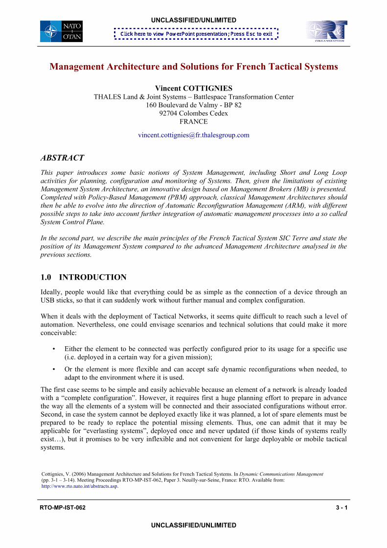
2.4.2 The Management Broker
A Management Broker (MB) is a mediator between the various kinds of end-system Managers (MGR) and the devices to be managed. Its characteristics are presented hereafter:
• A MB can compute aggregated and consolidated monitoring information in order to provide consistent macroscopic Management Views to MGRs, while the detailed monitoring information could still be available from a local or a remote display.
• A MB is able to configure and monitor a group of heterogeneous physical devices within a given Management Domain. It can thus provide Infrastructure-oriented Management Views to Infrastructure MGRs, given their interests in network appliances, computers, servers, antennas, cables…
• A MB also provides functional Service-oriented Management Views to Service MGRs, which consist in an abstraction view of the system structured per service. It provides thus capability to dedicate some MGRs to be more focused on the management of functional services that can be grouped in classes like Security (MGR SEC), Networking (MGR NET) and Communication Services (MGR SRV).
• In order to cope with the problem of the heterogeneity of vendor-specific solutions, MBs provide an abstraction view of the elements managed through Functional Components. An Infrastructure MGR manages Infrastructure Components that represent Classes of physical devices, while

Management Architecture and Solutions for French Tactical Systems
3 - 8 RTO-MP-IST-062
UNCLASSIFIED/UNLIMITED
UNCLASSIFIED/UNLIMITED
Service MGR manages Service Components that represent the elementary entities that must collaborate to provide a global a Service or a Class of Service.
Examples of Infrastructure Components, identified as EQT (EquipmenT) on the next figure, are:
• EQT Classes: Firewall, Router, Switch, Server, Computer…
• EQT Type: Small, Medium, Large
Examples of Service Components are:
• Communication Services Class (SRV): LCC Components (Local Call Control) and GW Component (GateWay) for Telephony Service, MCU Components (MultiConference Unit) for Audio & Videoconferencing Service, MSG Components (MeSsaGing) for E-Mail Service, WEB Components…
• Networking Services Class (NET): L3P Components (Layer 3 Protocol) for Routing Service, L2P Components (Layer 2 Protocol) for Switching Service, TAD Components (Transmission Adaptation) for Transmission Media Service (like the specific mapping of packets on a TDMA radio for instance)…
• Security Services Class (SEC): FRW Components (FiReWall) for Firewalling Service, DMZ Components (De-Militarized Zone) for Security Proxying Service, IPZ Components (IP Encryption) for IPSec VPN Service…
• There may exist dependencies between the Service Components and the Infrastructure Components that must support the Services during run time. This could lead to conflicts that must be solved by the MBs as most as possible automatically
• Thanks to the Functional Components handled by the MB, several MGRs can concurrently modify different information as if they could simultaneously manage the same devices. However, because of dependencies between Components, when contradictory actions expected by several Service and Infrastructure MGRs cannot be solved automatically by the MBs, they can provide a diagnostic to help the MGRs to take a decision.
• The MBs achieve translation between the abstraction language of the MGRs (to hide the heterogeneity of vendor-specific solutions) and the proprietary data mode and transport protocol of each device managed (e.g. CLI_CISCO/Telnet, CLI_Linux/FTP, MIB_II/SNMP, Proprietary_Data_Model/ Proprietary_Transport_Protocol…).
• Finally, the MBs is at the core element of an Autonomous Reconfiguration Management (ARM) and is able to compute the new configuration to be applied to the devices according to the policies retrieved from a local or remote Management Policy Repository and the System Data Model.
Management Architecture and Solutions for French Tactical Systems
RTO-MP-IST-062 3 - 9
UNCLASSIFIED/UNLIMITED
UNCLASSIFIED/UNLIMITED
R1CISCO3650
R2CISCO3650
R3JUNIPER6000
S1Linux RH6
S2Linux RH6
S3MS XP
S4MS XP
F1Arkoon
F2Arkoon
Infr
astr
uctu
re
SmallRouter
SmallRouter
LargeRouter
LargeServer
LargeServer
SmallServer
SmallServer
SmallFirewall
SmallFirewall
Secu
rity
DMZ FRW FRW
Net
wor
king
L3P L3P L3P
L3PL2P
Device Mapping Layer
Management Broker (MB)
Com
m. S
ervi
ces
LCC MSG
WEB
MCU
ConfigurationPolicies
SystemData Model
ARM
Several Proprietary CLIs
Component Mapping Layer
MGR NETMGR SRV MGR SEC MGR EQT
Homogeneous protocol for management of functional Components & Services
Figure 6: Management Broker Principles
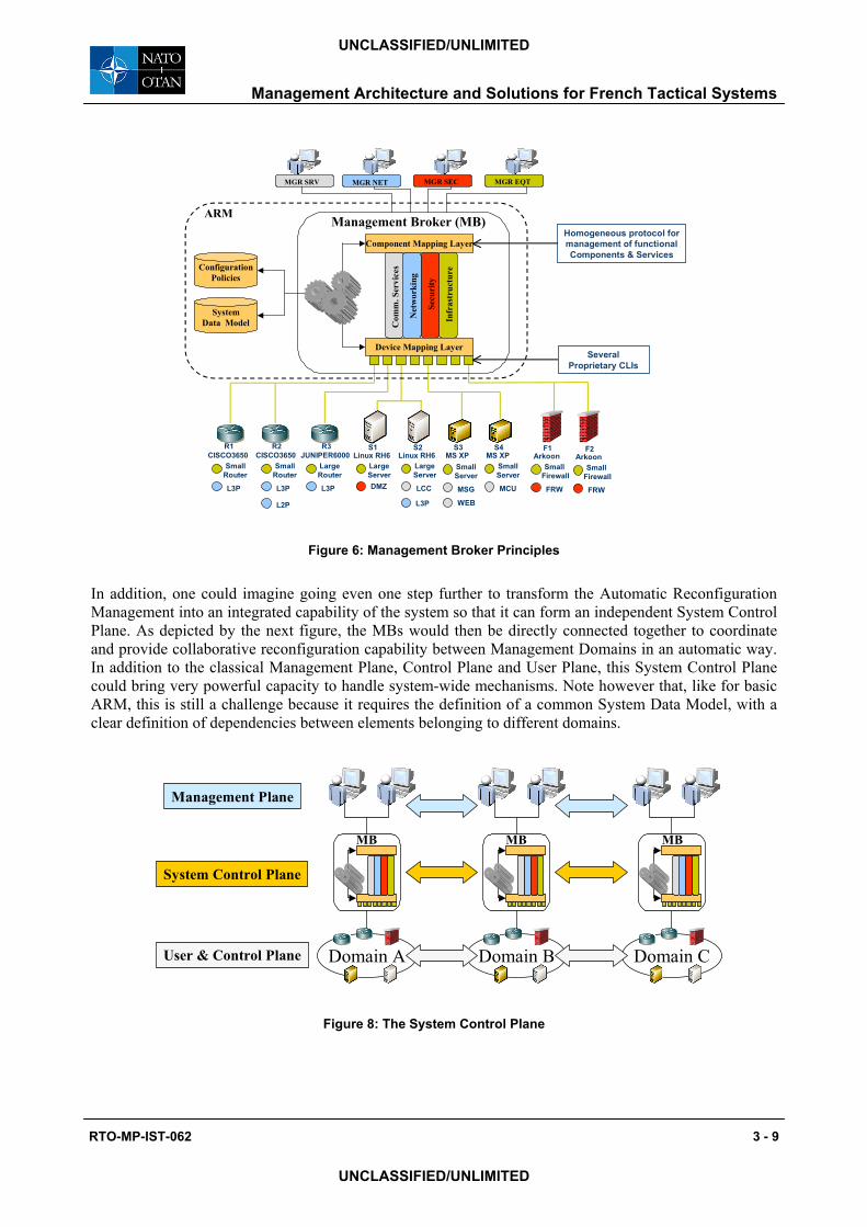
In addition, one could imagine going even one step further to transform the Automatic Reconfiguration Management into an integrated capability of the system so that it can form an independent System Control Plane. As depicted by the next figure, the MBs would then be directly connected together to coordinate and provide collaborative reconfiguration capability between Management Domains in an automatic way. In addition to the classical Management Plane, Control Plane and User Plane, this System Control Plane could bring very powerful capacity to handle system-wide mechanisms. Note however that, like for basic ARM, this is still a challenge because it requires the definition of a common System Data Model, with a clear definition of dependencies between elements belonging to different domains.
Domain A Domain B Domain C
MB
User & Control Plane
System Control Plane
Management Plane
MBMB
Figure 8: The System Control Plane

Management Architecture and Solutions for French Tactical Systems
3 - 10 RTO-MP-IST-062
UNCLASSIFIED/UNLIMITED
UNCLASSIFIED/UNLIMITED
2.4.3 Application of Management Broker principles
The Management Broker relies on a powerful and extensible concept that can typically be used for:
• Initial configuration of devices of a system at first start after deployment;
• Automatic application of a new configuration plans to devices of a system already running;
• Automatic reconfiguration of device of a system on failure detection;
• Automatic discovery and reconfiguration of interfaces between interconnected systems.
The last example is depicted on the figure hereafter.
Network BNetwork A
Broadcast Media
(0): Physical Connectionof Network A viaBorder Router A
(1b): Discover Capacities(1a): Publish Capacities
(2):CheckA B
&A C
(4): Reconfigure(only A B)
Con
figur
atio
n&
Ppo
licy
Rep
osito
ry
Manager A
MBMB
MB
(3): ValidationRequest or Advice(Config. A B)
Network C
Manager C
Con
figur
atio
n&
Ppo
licy
Rep
osito
ry
Manager B
BorderRouter B
PublishDiscover
BorderRouter A
Rep
osito
ry
Figure 7: Automatic Network Interconnection
In this example coming from the ETNA Eurofinder Project, the following things happen after the physical interconnection of Border Router A to the Broadcast Media (which may be for instance a switch Ethernet infrastructure or a broadcast satellite):
• A Service Discovery phase during which each MB publishes the capabilities of the Network it represents (1a) and discovers the capabilities announced by the other networks (2a). In this example, MB of Network A discovers the capabilities of Network B & C published by their respective MB;
• In order to take a decision on the possible and authorised interconnection with Network B and C, MB of Network A checks the policies and configuration parameters in the Repository (2). In this case, the answer says that only a connection with Network B is possible;
• Then, depending on the mode of action of the MB, it can advice the Manager of the choice made (automatic mode) or ask for a validation and/or for complementary information to a Manager (3);
• Finally, the Border Router A is reconfigured with the parameters required to allow exchanges between Network A and Network B through the broadcast media under the conditions imposed by the Repository.
N.B. Even if it is not shown on the figure, the same actions of reconfiguration can also happen at Network B.

Management Architecture and Solutions for French Tactical Systems
RTO-MP-IST-062 3 - 11
UNCLASSIFIED/UNLIMITED
UNCLASSIFIED/UNLIMITED
3.0 SIC TERRE TACTICAL MANAGEMENT SYSTEM ARCHITECTURE
3.1 Military ISP Principles A Military ISP is inspired of the civilian ISP and aims at providing Tactical Internet (TI) on the battlefield. It allows secured interconnection of enclaves through Military IPSec VPNs; through border services provided by TACs (Technical Access Centers).
The ISPs rely on IP Network Providers (INP) to deliver IP connectivity via a black IP backbone on which they can plug to interconnect their Technical Centers and associated enclaves. The ISPs not only provide IP connectivity but also service connectivity through proxys provided by the TACs and central intermediate service and management centers located at TOCs (Technical Operational Centers).
Interconnection of low capacity networks is realised through adapted TACs (TAC-Radio) that provide transport protocol optimisation for low capacity networks (e.g. CNR: Combat Net Radio) but without IPSec. External interconnection is provided through TICs (Technical Interconnection Centers) that include security gateways for the secured interoperability of services with other systems.
INP
Black IP Backbone(composed of INPs)
TAC: Access Center(with IP Crypto and DMZ)
TOC: Operational Center(Central Mgt & Services)
MC VPNNS VPN
CNRCNR
Secured CNR Network
VehiculeLAN
CNRLow capacity
Radio Networks
TAC-R: Access Center - Radio(without IP Crypto or variantsand Appli/Protocol Gateways)
Secured EnclaveMilitary ISP
Technical Centers
Military ISP provide:
1/ Secured Networking connectivity(Crypto, Authent.,Filtering, DMZ)
2/ Common Communication Services(Multimedia,Web, Directory, DataDissemination, Location service...)
3/ TI System Management(ISP Manager & Brokers)
ExternalSystems
TIC: Interconnection Center
INP
INP: IP NetworkProviderISP: Internet/Intranet Service Provider
Figure 9: Military ISP Principles
3.2 Military Secured Enclaves As depicted by the figure hereafter, an enclave of a given security level is protected by an IPSec Crypto device (IPZ) and composed of different devices (Switch, Router, Firewalls, Servers, Terminals, Gateway & Radios) managed locally by the Local Management Center (LMC).
The LMC is composed of the following building blocks:
• A MB handles mediation interface with the local elements of an enclave for exploitation by its local MGR and ensures communication with remote Central Management Center (CMC);
• MGRs can have access to different management views: Devices, Communication Services, Networking and Security (excluding IPSec Crypto and Key management);

Management Architecture and Solutions for French Tactical Systems
3 - 12 RTO-MP-IST-062
UNCLASSIFIED/UNLIMITED
UNCLASSIFIED/UNLIMITED
• A Configuration Repository, based on an LDAP Directory (DIR), provides the necessary information for the autonomous operation of the LMC (i.e. without any CMC active), assuming the DIR have been correctly initiated by the CMC (and continuously updated).
Enclaves of different Security Levels
Black IP Backbone
IPZ
Gateway& Radio
Low Capacity Radio Nets
MGR NET
MGR SRV
MGR SEC
Local Management Center (LMC)
MGR EQT
Local Services
ServiceProxys
MBDIR
LDAP
NetConf
SNMPProprietary CLI
MGR NET
MGR SRV
MGR SECMBDIR
Central Management Center (CMC)
MGR EQT
MGR IPZ
Figure 10: Management of a Secured Enclave
Compared to a LMC which is collocated with the enclave it is in charge of, a CMC is located at a central TOC (Technical Operational Center). The CMC can access to a synthetic view of the information retrieved from the different LMCs and can request modification to LMCs to ensure the global consistency of an operation. In addition, the CMC includes a dedicated Manager for on-line management of IP Cryptos of the secured enclaves.
3.3 Management Architecture The ISP Management System of SIC Terre is based on the “Plan, Pre-configure, Deploy, Start & Reconfigure” paradigm presented in section 2.3. As a consequence configuration and reconfiguration of the system is optimised thanks to integrated Long Loop mechanisms and Short Loop capability for rapid application of predefined configuration plans.
To do so, the Management System is based on MBs; one in each secured enclave. In the current version of the system, the MBs do not obviously support all the functions described in section 2.4.2, but one can already find some core capacities as presented hereafter:
• The LMC of an enclave is able to manage different set of services (Security, Networking and Communication Services).
• MBs implement DEN principles with LDAP Directories able to provide the Configuration of elements to be applied by the MBs to the elements managed.
• MBs can manage Infrastructure Components and Service Components thus providing a level of abstraction of the elements managed.
• As SNMP is known to be inadequate for configuration commands (while it is also known to be quite efficient for monitoring), each vendor provides also a proprietary but more efficient interface for configuration. Then, the MBs play the role of mediators for the configuration and ensure protocol adaptation between the proprietary protocol of each element managed and the MB.

Management Architecture and Solutions for French Tactical Systems
RTO-MP-IST-062 3 - 13
UNCLASSIFIED/UNLIMITED
UNCLASSIFIED/UNLIMITED
• At the interface between the MBs and the MGRs, as the problem of inadequacy of SNMP for configuration remains, it has been chosen to replace it by NetConf [4] which is much more adapted to configuration management, with more flexible formats for the data models thanks to XML.
There is no fully Automatic Reconfiguration Management capability yet; only the Managers are allowed to request a reconfiguration according the information retrieved from the Configuration Directory. Nevertheless, it is interesting to note that the system provides Localisation & Mobility Service that can be viewed as a first step towards a System Control Plane.
The overall organisation of the management system, as depicted on the next figure, has the main following characteristics:
• Each ISP includes a Management Backbone based on MBs to which LMCs and CMCs (also called ISP Manager) are plugged. There is one such Management Backbone per Security Level.
• In order to avoid single point of failure, the active CMC is replicated with a passive CMC able to become active when needed. In addition, each enclave includes a LMC for being able to work autonomous if necessary (e.g. in case a secured enclave is disconnected from the ISP, or when the CMC is unreachable…).
• A TCC (Theatre Coordination Center) is in charge of the coordination between the ISP Managers on a theatre and with the reach back central management entity in charge of the global coordination of resources between all theatres and the metropolitan infrastructures.
• In addition, the ISP Managers coordinate the planning with Managers of other systems; INP Managers that provide the black IP networks on which the ISP rely, Off-Line IPSec Key Managers for preparing the keys that will be used by IPSec Crypto on the field and Radio Managers in charge of the planning of frequencies and keys.
x (N1 Security Levels) x (N2 ISP)
MGR NET
MGR SRV
MGR SECMB
DIR MGR EQT
LMC
MGR NET
MGR SRV
MGR SECMB
DIR MGR EQT
LMC
MGR NET
MGR SRV
MGR SECMB
DIR MGR EQT
LMCMB
DIR
MGR NET
MGR SRV
MGR SEC
MGR EQT
LMC
MB
DIR
MGR NET
MGR SRV
MGR SEC
MGR EQT
LMC
MB
DIR
MGR NET
MGR SRV
MGR SEC
MGR EQT
LMC
MGR NET
MGR SRV
MGR SEC
MB
DIRMGR EQT
LMC
Local
MB
DIR
MGR NET
MGR SRV
MGR SEC
MGR EQT
LMC
Local
MB
DIR
MGR NET
MGR SRV
MGR SEC
MGR EQT
Passive CMC
Central
MGR NET
MGR SRV
MGR SEC
MB
DIRMGR EQT
Active CMC
Central
Network
INP Managers
IPZ KeyManagers
RadioFreq & KeyManagers
Theatre Coordination Center
Figure 11: ISP Management System Organisation

Management Architecture and Solutions for French Tactical Systems
3 - 14 RTO-MP-IST-062
UNCLASSIFIED/UNLIMITED
UNCLASSIFIED/UNLIMITED
4.0 CONCLUSION
Given the large set of heterogeneous devices composing a Tactical Network, the complexity of each of them and the dynamic evolution of their role and their interconnection on the battlefield, the management of such systems may become complex and inefficient. As a consequence, well-designed management architecture are necessary.
The concept of Management Broker (MB) can provide flexible and powerful solutions for building a kind of Management Backbone to which various manageable elements can be efficiently connected. So, while playing the role of an intermediary between simultaneous Managers (MGR) and the elements managed, the MB eases initial configuration and subsequent automatic or semi-automatic thanks to reconfiguration policies implemented through Directory Enabled Network (DEN) capability.
Following the XML & SOAP technological trends, NetConf provides an elegant technical solution to overcome the drawbacks of SNMP for the configuration tasks, while conceding that SNMP will continue to be very valuable for monitoring. An architecture based on MBs can then take great benefits of NetConf for the communications with the MGRs because it can hide the specific protocols used to configure at the end the elements managed.
However, one must recognize that existing operational Tactical Networks can hardly deploy automatic reconfiguration policies functions. Although it can easily be done for simple cases (like for a global change of configuration of a network, or for hot recovery on failure, thanks to dynamic reconfiguration of a back-up for instance), it becomes almost impossible to achieve for complex cases. Indeed it requires then a complete System Data Model including dependencies between the elements of the system.
There is thus a challenge for research to be completed around System Data Models. The task may be hard and can conduct far beyond the simple definition of a new type of Management Information Base (MIB), because new complex system-oriented models are required in addition to the existing device-oriented models (like MIBs) and the validation of all possible system configurations in advance (like predefined Blue Prints) may be very complex.
5.0 REFERENCES
[1] Directory-Enabled Network: DMTF & TeleManagement Forum (www.dmtf.org & www.tmforum.org)
[2] Policy-Based Management (www.simpleweb.org/nm/research/results/publications/boros/eunice2000.pdf)
[3] Common Information Model (www.wbemsolutions.com)
[4] NetConf (www3.ietf.org/html.charters/netconf-charter.html)