management command unclassified · ad-ai1 764 military traffic management command transportation...
TRANSCRIPT
AD-AI1 764 MILITARY TRAFFIC MANAGEMENT COMMAND TRANSPORTATION EN--ETC F/6 15/5
RAIL AND MOTOR OUTLOADING CAPABILITY STUDY. CAMP RIPLEY, MINNES-ETC(U)JAN GO .1 H GRIER
UNCLASSIFIED MTMC-TE-79-- 4 SBIE-AD-ET5O 079 NLLEEEEEEI/EEEE
*flf flfl lflf fl*END

- ~M. P

MTMC REPORT TE 79-4-48
RAIL AND MOTOR OUTLOADING CAPABILITY STUDY
CAMP RIPLEY, MINNESOTA
DTIC TABUnannounced
Ja u r 9 0Distributio3n/
TRANSPORTATIONAvaElabIlNtI Code
i Special
Project Engineer
John H. Grier, PETraffic Engineering Division
MILITARY TRAFFIC MANAGEMENT COMMAND
TRANSPORTATION ENGINEERING AGENCY
Newport News, Virginia 23606
A~ovd impubUa ze*Ci53%P",~hlb, qmUmlm~m I,
TABLE OF CONTENTS
Page
LIST OF ILLUSTRATIONS.......... v
LIST OF TABLES.......... . . vii
EXECUTIVE SUMMARY...........
I. INTRODUCTION............ 6
I. ANALYSIS OF CAMP RIPLEY'S RAIL OUTLOADINGFACILITIES.... . .......... 9
A. General............ . 9B. Rail Facility Description.. ...... . 9
C. Current Procedures ...... . . . .... . . 10D. Rail System Analysis ...... . .... 17
1. Current Outloading Capability. . . .... 172. Rail Outloading Analysis. . ..... . 17
3. Rail System Outloading Options. .... . . 21
4. Physical Improvements and Additions .. 23
5. Analysis of Railcar Requirements .. 24
6. Discussion of Titne and Costs.... . . . 24
III. ANALYSIS OF COMMERCIAL RAIL FACILITIES WITHINTHE CAMP RIPLEY AREA..... . . ... 35
IV. SPECIAL EQUIPMENT FOR EXPEDITING THEOUTLOADING OF MILVANS ......... 42
V. ANALYSIS OF MOTOR SYSTEM OUTLOADINGCAPABILITY...... . . . ...... 43
iii
Lmm .

II
TABLE OF CONTENTS - cont
Page
A. General ........ ........ . 43B. Motor Loading Facilities .. ...... .. 43C. Flatbed Semitrailer Outloading... . .... 43D. Van Semitrailer Outloading...... . . . . 46
VI. CONCLUSIONS . ............. 47
VII. RECOMMENDATIONS ........... 49
APPENDIXES
A - Track Safety Standards .... .. ....... 50B - Proposed Rail Outloading Procedure for a
Mobilization Move at Camp Ripley ..... 63C - Special-Purpose Railcars and Loading/Unloading
Procedures ...... .......... 69D - Department of Transportation - Federal Railroad
Administration, Camp Ripley Track InspectionReport ....... .......... 75
DISTRIBUTION ...... ....... .. 78
iv
ivi
LIST OF ILLUSTRATIONS
Figure Page
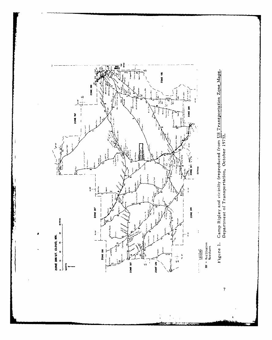
1 Camp Ripley and vicinity ... ... . ......... 7
2 Camp Ripley rail system .... ...... . .11
3 Tracks Li (right) and L2 (left), easterly view . . . 14
4 Track Li, side-loading ramp with two boxcar positions 14
5 Track Li, side-loading ramp, one boxcar position,
(extreme right). Side-loading dock (left) . .15
6 Track L3, southeasterly view ... ... .. . 15
7 Track L5 (BNRR main line at Camp Ripley entrance),portable end ramp to be placed at upper right, north
of south leg of wye ...... ....... .. .16
8 Track L5 (BNRR main line south of Camp Ripley
entrance), southerly view .... ..... .16
9 Circus-style loading of 2-1/2-ton trucks . . . .. 26
10 Lower level of bilevel cars loaded with jeeps, gamagoats, 3/4-ton trucks, and 1-1/4-ton trucks . . . 30
11 Administrative loading, mules ... ..... . .30
12 Administrative loading, 1/4-ton trailers. ... . . 31
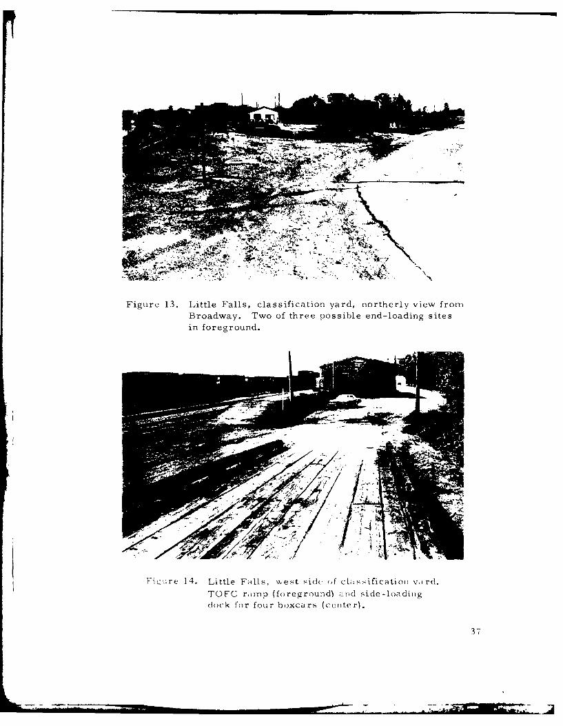
13 Little Falls, classification yard, northerly view fromBroadway. Two of three possible end-loading sites
in foreground .. ...... ....... 37
14 Little Falls, west side of classification yard. TOFC
ramp (foreground) and side-loading dock for fourboxcars (center) . ........... 37
v
A

LIST OF ILLUSTRATIONS - cont
Figure Page
15 Little Falls, east side of river, northerly view fromBroadway...... ... .... .... 38
16 Little Falls, east side of river, southerly view fromBroadway .............. 38
17 Randall, northerly view. Main line track (right), longsiding (center), one of short sidings (left), withloading site... ..... ..... ..... 39
18 Royalton, southerly view. Two main line tracks(center), siding (right), and spur (left)...... .... 39
19 Royalton, northerly view from south end of spur .. 40
20 Belle Prairie, northerly view. Main line track
(center), spur (right), highway US 371 (left) . . . . 40
21 Concrete end-loading ramp, three positions, left side offigure... ... ..... ..... ... 44
22 Earth/timber ramps, two positions... ...... 45
23 Rail outloading simulation, Camp Ripley ... ..... 64
vi
LIST OF TABLES
Table Page
1 Rail and Motor Outloading Capability ... .. ..... 3
2 Camp Ripley Rail Outloading Facilities .... .. 13
3 Times Required to Perform Various Loading Functions 19
4 Camp Ripley Rail System (and BNRR Near Camp Ripley)Outloading Options ...... ..... . .
5 Armored Division and Support Units RailcarRequirements........... . . 24
6 T)?ical Site Loading and Blocking and Bracing Times
(Total) ...... ..... ..... 27
7 Cost Comparison, Bilevels Versus 54-Foot Flatcars 33
8 Rail Facilities Within 25 Miles of Camp Ripley . . 36
9 Vehicles End-Loading Ramps and Docks . .... . 44
10 Times Required for Various Railcar Switching Operationsand Locomotive Capability .. ..... ... 67
11 Trailer Train Company Fleet ... ....... .71
vii
• p ( •
EXECUTIVE SUMMARY
1. SCOPE
The Military Traffic Management Command (MTMC) conducted asurvey of rail and motor facilities at Camp Ripley, Minnesota, inJune 1979, to determine the installation's outloading capability.Rail facilities within 25 miles of Camp Ripley were included in thesurvey.
2. FINDINGS
The primary finding is that Camp Ripley does not have sufficient railfacilities to meet the current mobilization requirement; consequently,facilities of the Burlington North Railroad (BNRR) will be requiredfor approximately one-half of the requirement. Since the BNRR isplanning to abandon their main line track north of Camp Ripley,leaving the main line south to Little Falls for access, the main linetrack near the entrance to Camp Ripley can be used for loading sitesto outload the shortfall.
To transport the equipment of the mobilized 47th Division and support-type units entirely by rail would require 2, 058 railcars, with anestimated composition of 1, 990 flatcars (1, 679 for roadable and 311for nonroadable equipment) and 68 boxcars- . Since the installationoutloading plans were incomplete and no time frame had been estab-lished for unit outloading, the analysis in this report is based on a10-day outloading. During the outloading period no railcar loads ofnonroadable equipment are scheduled to arrive.
Camp Ripley has approximately 3 miles of railroad track. The railtrackage is classified as Class 1, according to the Federal RailroadAdministration track safety standards, and needs to be upgraded toClass 2. There are rail facilities in Little Falls, Minnesota, about9 miles from Camp Ripley, that would be suitable to support CampRipley's outloading.
The current rail outloading capability at Camp Ripley is limited byinsufficient rail end-loading ramps, the existence of sections of
I/Since most flatcars are 57 feet long (coupler-to-coupler, that length isused in this report; to convert to any other length, simply multiply thenumber of cars by 57 and divide by the desired length in feet.
1 k

Class 1 track, and shortages of small handtools, bridgeplates, andblocking and bracing materials. Also lacking for maximum efficientoutloading operations are adequately trained blocking and bracingcrews as well as completed outloading plans.
The recommended rail outloading plan, Plan 4, would yield 206 rail-car loads per 24-hour period (106 from Camp Ripley and 100 fromthe BNRR main line near Camp Ripley). Other options, producingrailcar loads of 49, 99, 156 (all equipment), and 106 (nonroadableequipment only), are presented in this study. Plan 4 satisfies the re-quirement to outload all equipment of the division and supporting unitswithin approximately 10 days.
A survey of loading ramps/docks and other equipment suitable forloading semitrailers revealed that, although the actual availabilityof semitrailers cannot be predetermined, the motor outloading capa-bility of Camp Ripley exceeds the probable supply of availablecommercial trailers.
Table I shows the current and potential outloading capabilities (bothrail and motor) of Camp Ripley.
3. CONCLUSIONS
a. The BNRR currently plans to abandon their main line track northof Camp Ripley Junction; 6, 400 feet of this main line track,north of the north switch of the Camp Ripley wye, is needed formobilization requirements. (Arrangements have been completedby MTMC and BNRR to retain the needed trackage.)
b. Most of Camp Ripley's railroad trackage is classified asClass 1- / , according to federal track safety standards. Minormaintenance on deficient sections would upgrade all trackage toa Class 2 condition.
c. Other constraints limiting Camp Ripley's rail outloading capa-bility are a shortage of blocking and bracing materials, smallhandtools, and bridgeplates; insufficient trained blocking andbracing crews; and a lack of outloading plans.
-/AR 420-72, 24 March 1976, Surfaced Areas, Railroads, and AssociatedStructures, para 3-15a, states that track on military installations willbe maintained to the minimum track safety standards required forClass 2, as outlined in the current Department of TransportationFederal Railway Administration Track Safety Standards (app A).
2
i a

TABLE 1
RAIL AND MOTOR OUTLOADING CAPABILITY
Rail
Number and Type of Railcars(57-ft Len th, Coupler-to-Coupler)
Total CurrentRate Flatcars Boxcars Outloading Constraints
Daily Current 6 3 9 Lack of personnel
Daily Mobilize 218 11 229 /
Lack of blockingand bracingmaterials, small
handtools,bridgeplates,outloading plans,trained blockingand bracingcrews, end-
I loading ramps.
Plan 4 19 9/ 7 2 06Wb /
Same--(trackmaintenance.I concrete and2 portable tim-ber end ramps$15,000, or 3timber ramps
-- $7,500)
Nonroadableequipment only 99 7 106 Same--(track
maintenance.1 concrete endramp $10,000 orI timber ramp$2,500.),
Motor
Number of Trailer, at
Available Facilities
Van Semi- Total CurrentRate Flats trailers Outloading Constraints
Daily Current:Concurrent (with 6 4 10 Limitedrail operation) by personnelSeparate (without 6 4 10rail operation)
Daily Mobilize:Concurrent (with 32 / 82 Van loading -
rail operation) d forklift trucksSeparate (without 110- 32k' 142 and side load-rail operation) ing docks at
I warehouses
- /At Little Falls classification yard, 9 miles distant;includes two shortspurs south side and TOFC track, 19 flatcars and four boxcars at side-loading ramp, see figure 2.
6/Blocking and bracing materials not stocked.
dWith existing usable end-loading ramps.- Using all of c above plus all potential rail end-loading ramps./Using hand labor in trucks, except for one loading position, since only one
side-loading dock exists.

d. End-loading ramps are needed for the three additional identifiedloading sites, and side-loading docks will be needed for seven
boxcars per day.
e. After the deficiencies noted above are corrected and upon receipt
of sufficient railcars to permit full-scale outloading, Camp
Ripley could outload 106 railcars per 24-hour period. However,to meet the total requirement, 100 railcars will need to be out-
loaded per 24-hour period on the BNRR main line at Camp Ripley.
f. Empty railcars (dedicated train lengths) destined for Camp
Ripley should be positioned in train-loading sequence in LittleFall s.
g. Camp Ripley's transportation personnel should coordinate plan-ning of impending outloading operations with the BNRR repre-
sentatives at the earliest possible date.
h. For administrative-type moves, when leadtime is plentiful and
costs must be considered, special-purpose railcars (such as
bilevel autoracks, trailer-on-flatcar (TOFC), and container-on-
flatcar (COFC)) are more cost-effective than the standard types
and should be used to the extent they are available.
i. For mobilization moves, when time is more critical than cost,
the use of special-purpose railcars may not be possible becauseof the short leadtime and relatively short supply of these high-
demand cars.
j. Motor outloading is not a good alternative to rail because Camp
Ripley is more than 800 miles from any POE.
k. For concurrent rail and motor operations, 50 flatbed and 32 van
semitrailers could be loaded per 10-hour day (for daylightoperations only), and for separate operations, 110 flatbed and32 van semitrailers could be loaded during the same period,
This capability exceeds the probable available supply of semi-
trailers.
1. The maximum curvature of the railroad tracks is less than 12
degrees. Consequently, any known length of railcar can be used
on the installation.
4
i_
4. RECOMMENDATIONS
a. Use the BNRR main line track near the entrance to Camp Ripleyto outload the mobilization shortfall.
b. Undertake those items listed in section II, paragraph D4, "Physi-
cal Improvements and Additions." These improvements willprovide a rail system capability of 206 railcars per 24-hour day
as well as an effective rail system.
c. Prepare a detailed unit outloading plan, using the simulation in
appendix B as an example, specifying unit assignments at loadoutsites and movement functions.
d. Coordinate rail outloading plans with BNRR representatives at
the earliest possible date.
e. Initiate a rail facility maintenance program to insure an effectiverail system.
f. Provide advance training for blocking and bracing crews.
g. Station road guards at all railroad crossings during outloadingoperations, and provide all train crewmen with walkie-talkies toinsure a safer and more efficient operation.
h. Keep abreast of BNRR railroad maintenance plans on the main
line trackage to Little Falls.
i. Use special-purpose railcars (such as bilevel autoracks for smallvehicles, TOFC cars for semitrailers and vans, and COFC carsfor MILVANs) for administrative-type moves, and, as available,
for mobilization moves.
j. Provide warehousing for blocking and bracing materials andsmall-tool supplies.
k. Coordinate with MTMC any removal of railroad track that isincluded in the mobilization outloading plan.
1. Construct any new track with a maximum curvature of 12 degrees.
5
I. INTRODUCTION
An onsite rail and motor outloading study of Camp Ripley, Minnesota(fig 1), was conducted by the Military Traffic Management CommandTransportation Engineering Agency, Newport News, Virginia, during theperiod 4 through 7 June 1979. The principal objective of the study was todetermine the capability of the Camp Ripley rail system to support thedeployment of the 47th Division and support-type units. Another objectivewas to identify any physical improvement, as well as any suitable com-mercial rail facilities, within Little Falls, Minnesota, that would signifi-cantly increase the current capability. This study includes the findingsof a Federal Railway Administration (FRA) inspector, who inspected alltrackage at Camp Ripley during the onsite study.
The current rail outloading capability of Camp Ripley is limited by a lackof outloading plans and blocking and bracing materials, insufficient smallhandtools, inadequately trained blocking and bracing crews, and insuffi-cient end-loading ramps. Also, the current rail outloading capability islimited by the condition of some sections of installation rail trackage,classified as less than Class 2. The analysis in this study showed that,if these deficiencies were corrected and rail trackage were upgraded toClass 2, Camp Ripley could support an outloading rate of 106 railcarsper 24-hour day; this is not adequate to meet the mobilization requirementof 206 railcars per day. The 100-railcar per day shortfall can be reme-died by using the main line track of the Burlington Northern Railroad(BNRR) near the Camp Ripley entrance. With this combined rate, allunits required to outload during the peak period could be accommodatedwithin a 10-day period. This study considers options that could produce49-, 99-, 156-, or 206-railcar loads per 24-hour period and recommendsthe one with the 206-railcar yield (Plan 4). The nonroadable equipmentplan produces 106 railcars per day. Camp Ripley is served by the BNRRfrom its classification yard in Little Falls, Minnesota.
Motor outloading capability is not a consideration because Camp Ripleyis approximately 1, 200 miles from a suitable coastal port of embarkation(POE). Findings and recommendations contained in this report are basedon analysis of data obtained during the field survey and on other pertinentinformation relating to installation activities at that time. Any problemsincurred in implementing the recommendations should be referred toMTMCTEA for resolution.
6
__________ - - -- - ___~--~ -~-3---
OWOSi
a PuIN ___
LU U)
o -~ ~ 00± ~#4 3rd
r4~kE g,Ask
Q) 0
in , o >, '4
0.
LU)

Mail address is: DirectorMilitary Traffic Management CommandTransportation Engineering AgencyATTN: MTT-TEPO Box 6276Newport News, VA 23606
Telephone: AUTOVON 927-4641
8

11. ANALYSIS OF CAMP RIPLEY'S RAIL OUTLOADING FACILITIES
A. GENERAL
Discussions with personnel at Camp Ripley revealed that large-scalerail operations have not occurred there in recent years. Heavymilitary equipment is moved in and out of the installation by rail, formaintenance purposes or delivery. During the survey period fivecarloads of construction equipment were received. The BNRR pro-vides switching services, as required, as Camp Ripley has no switchengine or railcrews. Factual data about locomotive operating timesand blocking and bracing capabilities were gathered from previousstudies.
B. RAIL FACILITY DESCRIPTION
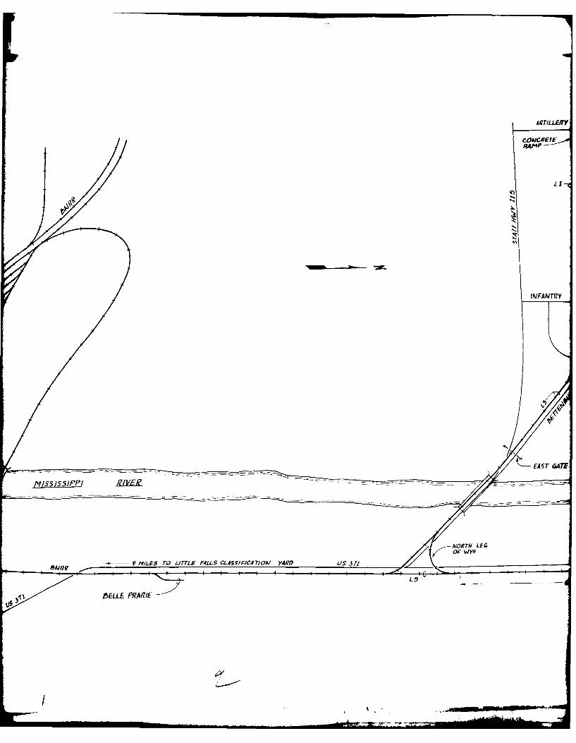
The Camp Ripley rail system, consisting of 3 miles of track, isillustrated in figure 2 and described in table 2. The survey of allsites that could be used for outloading equipment revealed that cur-rently only one site is equipped with an end-loading ramp to loadvehicles. This same track has two side-loading ramps with threerailcar positions. One other track at Camp Ripley is suitable forend loading vehicles, but an end ramp is needed. A portion of theaccess line can be used for boxcar loading. Due to limited trackage,facilities of the BNRR are required to meet the peak mobilizationrequirement. Since the main line of the BNRR at the entrance toCamp Ripley is under study for abandonment, but is suitable for load-ing sites, it is included in this section of the study for use in the out-loading plan.
Most of the trackage at Camp Ripley meets Class I standards only.The BNRR track north of Camp Ripley also is Class 1, but the partsouth of Camp Ripley to Little Falls is Class 2. Camp Ripley doesnot have rail maintenance personnel; consequently, needed repairsmust be accomplished by contract.
The following describes in detail the installation and BNRR sitesrecommended for loading railcars at Camp Ripley. The proposedloading sites, in descending order of preference, are:
South Spur (LI) is located on the south side of Rosenmeier Avenue.All Camp Ripley rail loading facilities are located along this track.These facilities consist of a concrete end-loading ramp (fig 3), two
9
side-loading ramps, and one side-loading dock (figs 4 and 5). Thisspur can be used to end load tracked or other heavy equipment.
North Spur (L2) is located on the north side of Rosenrneier Avenue.This track is suitable for end loading vehicles; however, a permanentor portable end ramp will be required.
East Gate A to East Exchange Road (L3) is a portion of the accessline into Camp Ripley. Since, except for one position, there are noside-loading docks on the warehouses along Rosenmeier Avenue, andthe tracks there are needed for vehicle loading, this site (fig 6) canbe used for boxcar loading. East Gate A (upper center) is closed,and the paved street adjacent to the track provides a good *work areafor forklift operations.
BNRR Main Line North of Main Gate (L4) extends approximately6, 400 feet north of the north leg of the wye leading into Camp Ripleyto provide adequate track for switching long strings of railcars in andout of the installation. Minor site preparation and a portable endramp will be required to end load vehicles. The site is similar toL5 shown in figures 7 and 8, with Highway 371 parallel and close tothe track.
BNRR Main Line at Main Gate (L5) is a portion of the rail access linesouth to Little Falls (figs 7 and 8). The graveled area betweenHighway 371 and the railroad track provides good access for vehiclesto be end loaded, using a portable ramp. The ramp will have to beremoved and replaced after each daily loading cycle.
Access to Camp Ripley's rail system and to the two loading sites onthe BNRR main line is good. Vehicles from motor pools and equip-ment from storage areas can be routed along good asphalt roads toany of the loading sites. This fact, coupled with the potential of therail system, indicates that Camp Ripley can develop sufficient capa-bility to successfully outload the division within a 10-day time frame.
C. CURRENT PROCEDURES
The BNRR serves Camp Ripley from its facilities in Little Falls,Minnesota. Access is on the east side of Camp Ripley, where theGovernment -owned track connects with the BNRR track running fromLittle Falls to Brainerd. Since Camp Ripley does not have anyGovernment -owned locomotives, the BNRR provides all switchings er vi c es.
10

rOFC RAP-
SIPE LOADING6 I?AMfP-- -
FALLS
I__,Aicusr(AL spups ANo /A/ A
R&ES/OENrIA1 AIEA
Figure 2. Camp Ripley rail system.
A1ZTILLFERY
INFA TR7Y
C' AST 647F
-MiSSiSSIfPPI
5A11?R f MILES WO ILME FALS CLASYIFCA 7/CAl YARP US 37!
j5ELLE PRARIE

TILLERV ROAD
CAMP
ROAP
EAST EXCMAAJOE P
4-4
GA TE "A F
- 76 /AJ/~ k,. -
,4 00 T - fi :4

0. '-40 00 a.4.4. I4.41 *.4.,4 C:1-1 . C: L 14-4 r4-4 4 14041 4100 0f 14 ' 10.I 400 bd 110 to4. .01. 04.44 41 4101 Ud 0A C 0 0) r1 '
01. W.-,,w4 w,- 1..14 0 0I-. -4 .- 4~ *4 0 0014~
C:4 4) 04 U. (4w10 41.l " 4 14.41 41) 141 4141,-..)U)
4110014-O 0 *4.4 141 14 a Q)C:
u- 0 0 0 0 0
04. '0 -0 0
f4 0. 00 0 00
w0 0 0 Q0
< 0 ~
4-H 04 0 0. 0w- 40. 0 0 r-0 0
4v a. (a 0
d) 04-4- 0 0 0
0z 0 0 "44 00 0 0 0LN W M M- L z
0 *V 0 0 z r'
w .04-4r044 440 -. 44 44 04 r r u0 cec 0
'a eg 4 M ~ M -, 1 S 00 i
04 0~4. (d 'a 'a M0
40 13

Figure 3. Tracks Ll (right) and L2 (left), easterly view.
Figure 4. Track Li, side-loading ramp with two boxcar positions.
14

Figure 5. Track Li, side-loading ramnp, one boxcar positioni,
(extreme right). Side-loading dock (left).
Figure 6. Track L3, southeasterly view.
15
Figre . TackLIsid-lodin rap, ne oxcr psiton
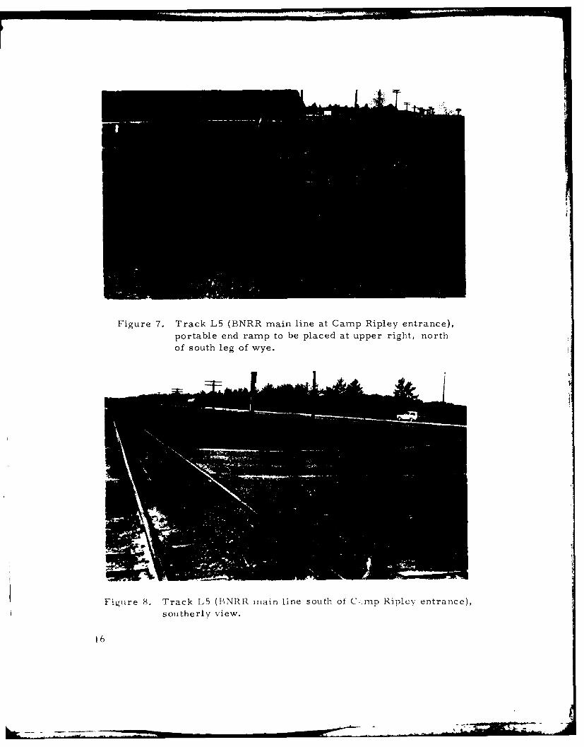
Figure 7. Track L5 (BNRR main line at Camp Ripley entrance),
portable end ramp to be placed at upper right, north
of south leg of wye.
Figure 8. Track L5 (1',NRR main line south of C>mp Ripley entrance),
southerly view.
16

Although most incoming supplies are delivered by truck, heavy equip-ment is delivered by rail. Currently, no rail outloading plans have
been developed by Camp Ripley personnel.
D. RAIL SYSTEM ANALYSIS
1. Current Outloading Capability
An ERA inspector conducted a survey of all Camp Ripley trackage
and found that the track meets ERA safety standards for Class 1.The trackage should be upgraded to Class 2 to support maximumoutloading operations. The ERA inspector's report is contained
in appendix D. Current rail outloading capability at Camp Ripleyis limited by the physical capabilities of the rail system and by
the shortage of small handtools, bridgeplates, and blocking and
bracing materials. Utilizing present facilities, Camp Ripley'smobilization outloading capability is approximately 106 railcarsper day. This outloading rate does not meet the requirement tooutload the proposed mobilized division and its support unitswithin a 10-day period. Use of end ramps, as identified in Plan
4, and use of the BNRR main line will increase the outloadingcapability to meet the mobilization outloading requirement.
Camp Ripley does not stock blocking and bracing material. Thesematerials are ordered when the requirement arises. Also needed
for a maximum efficient outloading operation are adequately
trained blocking and bracing crews and completed outloadingplans.
2. Rail Outloading Analysis
A complex system structure can be viewed as a series of inter-connected subsystems. The limiting subsystem within the system
establishes the maximum outloading capability. Therefore, in
ascertaining the maximum rail outloading capability of Camp
Ripley, the following subsystem separation was used:
a. Commercial Service Capabilities
Commercial service capabilities present no problem to
Camp Ripley. The common carrier serving the post is theBNRR and its operations in the vicinity of Camp Ripley
appear well organized. Also, since Little Falls, Minnesota,
17

has a classification yard about 9 miles from Camp Ripley,rail support for the outloading operation should not be a
major problem.
b. Moving to and Loading on Railcars at a Particular Site
The movement of cargo to loading sites is relatively quickand efficient since most of the equipment is self-propelled,and access is along good, paved roads. Traffic patterns andtraffic control would have to be set up, but such measures
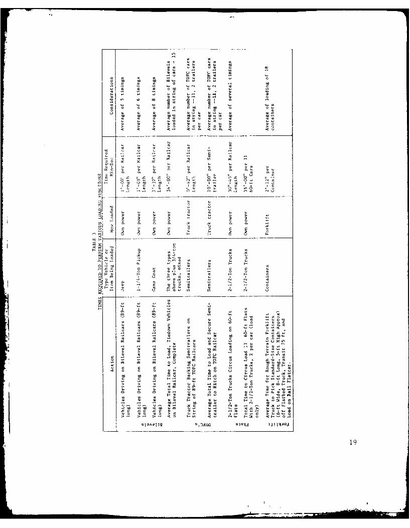
should be standard for full-scale outloading operations.Staging areas near the outloading sites are adequate, butqueuing will block some streets. Recent field tests, duringloading operations, revealed that vehicles move along theflatcars at an average speed of 1 mile per hour, with onlyone vehicle moving on a railcar at any one time. Thelongest string of empty flatcars used by the recommendedoutloading plan, assuming 57-foot car lengths (coupler-to-coupler), was 50 cars. Using that figure, the first vehiclewould reach the end of the last car 32 minutes after drivingup the ramp; then blocking and bracing could begin. Loadingtime is insignificant in comparison with blocking and bracingtime (table 3).
Therefore, moving to and loading on the railcars is not thelimiting subsystem. However, driving wheeled vehicles onflatcars "circus style" depends 7 n the use of bridgeplates tospan the gap between the cars.- According to the planemployed in our analysis, bridgeplates are required forsimultaneous loading at all sites where wheeled vehicles areto be loaded.
c. Blocking, Bracing, and Safety Inspections
Blocking, bracing, and safety inspection times are difficultto project. They depend on a number of variables such as:
(1) Crew size and experience.
(2) Extent of the safety inspection.
3'- Circus-style load--equipment is end loaded under its own power with
little or no effort to fully utilize all floor space on the railcar; time
is critical.
18
k .__ 7
10
001 101 00 c
r1 r10 V.0 0
01 - -
w 0 00 00 00. .11. 00w ww 60 V 0 M w 0 u- m c
>0 > >2 > 0 >1 w'0rw >
WH wW 21
o ' 0 0 01
10 ~ ~~~ r0 1 01 11U 11
) 10 r01
11~~C 111 0 11
10 10 10 U 0 I
. 10 10 1 0 10 I 0 -
In 0 r r :3 r 0
w- Ia 10a)- 1 - 1 0 0 0
> w U c
5 0j 0 0 0E 0In 0.0F. 0. .1 .1 . 0
003 C 0'III F 0
E-0 10 0. 10 1II.~ 000 0 0 .1
00~~0 10bo-1-1
010 w) w 0..Q0 0 0
U .. 4 r 0 U -3 H H
01- 1 1- ' I0 0 m1p0 H o 0 u0 10 10 H H0 WC 0
01 00 0 .0 10 U U I 1 u I
0. 0. 10 QU ca ul- -
> >10 'a 1 0 010 2l 20 .- I -H 01 I 1 .021 01 01 m F. 0
11 - - .1 H 01 I In IN IN
0000
'd m 14 U 01 U
H a c C U I I.1,m 0 ):
>0 v0 ,c .0 > w 10 >4 0
10 10 10 > 10 U 0 :30 0 - H
s4 ~ a~ q2 oao- 01UJ .I 0 0 '10 00 1.
10 10 10 ' '2 ' U 0 019

(3) Documentation.
(4) Availability of blocking and bracing material andmaterials handling equipment (MHE).
During REFORGER 76, the establishment, as a reasonablegoal for crews, of a 5-1/2- to 7-hour time limit for loading,blocking, and bracing at a loading site was based on experi-ence and actual field tests of circus-style loadings. In addi-tion, discussions with the blocking and bracing instructorsat the US Army Transportation School, Fort Eustis, Virginia,indicated that, to avoid wasted man-hours, there should be nomore than eight men per crew, regardless of experience.
At Camp Ripley, blocking and bracing materials and smallhandtools are in short supply. Procedures for obtainingthese items, which are available locally, should be plannedto assure that the division and its support equipment can beoutloaded within the time specified by the contingency plan.Blocking and bracing crews should be trained on a periodicbasis.
d. Interchange of Empty and Loaded Railcars
An efficient interchange of empty and loaded railcars re-quires careful planning and good coordination with the com-mon carrier. Such an interchange can be established atCamp Ripley because the BNRR has good rail access andadequate trackage for storage of railcars.
The existence of the BNRR railyard in Little Falls makes it.1 possible to accumulate the empty cars required for theoperation. The various plans for spotting railcars depend
on the type of operation. A place or location must be pro-vided for railcars (1) in empty storage, (2) in loadedstorage, and (3) at the loading sites. In general, threebalanced or equally divided areas must exist somewhere inthe vicinity. Empty railcars destined for Camp Ripley shouldbe accumulated and classified in Little Falls prior to beingmoved to Camp Ripley. Thus, if the interchange of railcarsfollows some semblance of the organization presented in thesimulation (app B), this subsystem will not limit the railoutloading capabilities of Camp Ripley.
20

e. Summary
Considering all the subsystems, the shortage of blocking andbracing materials, bridgeplates, and small handtools, alongwith the lack of trained blocking and bracing crews, emergeas the primary factors restraining any large rail outloadingoperation at Camp Ripley. Therefore, provision of theseitems is the major prerequisite for a successful operation.Another factor that affects station outloading at Camp Ripleyis the destination of the unit material after it leaves theinstallation. Since Camp Ripley's coastal POE is more than800 miles distant, all of the division equipment must go byrail.
This means that, for any major operation, a maximum effortwith consequent high outloading rates will be required.Although Camp Ripley's rail system and the common carrierfacilities serving it have the potential for supporting thedeployment of the division and other support units in a timelymanner, the actual capability at any one time will depend onthe capability of the supporting subsystem.
3. Rail System Outloading Options
The various options for outloading plans are shown in table 4.Five plans for daylight-only loading were developed, usingvarious combinations of recommended rail loading sites at bothCamp Ripley and the BNRR main line near Camp Riley.
As soon as the loading, blocking and bracing, and inspection ofthe cars are completed, the outloading operations may begin.Through proper planning, 120-ton locomotives can pick up loadedcars from the loaded tracks and bring empties for the next cycle.The exact procedure for all switching operations, arrival oflocomotives and empties, and departures is described in detailin the simulation for Plan 4 in appendix B. Four plans weredeveloped to provide the approximate daily outloading rates of
50, 100, 150, and 200 railcars for all the equipment and oneadditional plan of 106 railcars for the nonroadable equipmentonly. All plans function similarly.
Plan 1 uses track LI, located on the south side of RosenmeierAvenue, to produce an output oof 49 railcars per day. Plan 2 addstrack LZ, which fully utilizes the entire loading area alongRosenmeier Avenue, for a total of 99 railcars per day.
21

0(4 10 x x )
0 w0
(4>
.0
t 0 0.- 0 C.141 I
z <
r0 4
CL.4 '
p- 0 0w
Z (4>
0. C: t
r- 0~ -
. 4 0 < cu w ,
E, U4 c, Z4 (4 '0 z .)0 (4 0
'00 Q)4
4) 0 (4 .
u. W s.
m 4 (4. 0 ~ ' 1
(4 0 :
0 00.0 o m 2- 4-
t 400p 0 " a 0
(4 0
14 0 0.4 a. s'40.w(u
0- 0l (44(F40' 0 U)4
0~~~ (444A(44.
~0 000
-4) 0 4
0n (4 00 0-4 In $ m
04 " ' 0 F- 0.a04 (4u 0
(4(4u 0 ~ 440.~ w.- 'A4 00
22 '14(0

Plan 3, which produces an outloading rate of 156 railcars perday, requires the addition of tracks L3 (a portion of the postaccess line) and L4 (a portion of the BNRR main line) near theCamp Ripley entrance.
Plan 4, the recommended plan, adds track L5 (a portion of theBNRR main line near Camp Ripley) and is shown in detail inappendix B. This plan achieves an outloading capability of 206railcars per day, which fulfills the requirement to outload thedivision and the other mobilized units within approximately 10days.
The nonroadable equipment plan uses tracks Ll, L2, and L3 forthe movement of all nonroadable equipment during the peak out-loading.
4. Physical Improvements and Additions
Items listed below are all minimum requirements to provide therecommended outloading rate of 206 railcars per day (Plan 4)using existing trackage at Camp Ripley and portions of the BNRRmain line track near Camp Ripley.
a. Repair track deficiencies indicated in the FRA trackinspection report (app D).
b. Plan/program for:
(1) Construction of a concrete end-loading ramp at track L2.
(2) Construction of two portable timber end-loading rampsto be used at loading sites L4 and L5 on the BNRR nearthe entrance to Camp Ripley.
c. Establish the procedures for rapidly acquiring:
(1) A minimum stock of blocking and bracing material tosupplement the post organic supply for handling allequipment when a rapid deployment of post units isrequired.
(2) Bridgeplates for volume outloading of wheeled vehicles.
(3) Sufficient small tools to permit operation of blocking andbracing crews at all outloading sites. This includes
23
powersaws, cable cutters, wrecking bars, cable-tensioning devices and hammers.
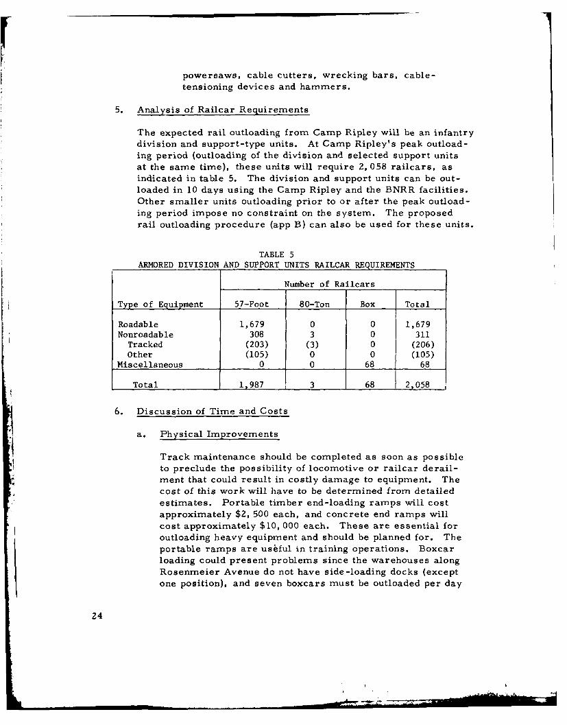
5. Analysis of Railcar Requirements
The expected rail outloading from Camp Ripley will be an infantrydivision and support-type units. At Camp Ripley's peak outload-ing period (outloading of the division and selected support unitsat the same time), these units will require 2, 058 railcars, asindicated in table 5. The division and support units can be out-loaded in 10 days using the Camp Ripley and the BNRR facilities.Other smaller units outloading prior to or after the peak outload-ing period impose no constraint on the system. The proposedrail outloading procedure (app B) can also be used for these units.
TABLE 5
ARMORED DIVISION AND SUPPORT UNITS RAILCAR REQUIREMENTS
Number of Railcars
Type of Equipment 57-Foot 80-Ton Box Total
Roadable 1,679 0 0 1,679Nonroadable 308 3 0 311
Tracked (203) (3) 0 (206)Other (105) 0 0 (105)
Miscellaneous 0 0 68 68
Total 1,987 3 68 _2,058
6. Discussion of Time and Costs
a. Physical Improvements
Track maintenance should be completed as soon as possible
to preclude the possibility of locomotive or railcar derail-ment that could result in costly damage to equipment. Thecost of this work will have to be determined from detailed
estimates. Portable timber end-loading ramps will cost
approximately $2, 500 each, and concrete end ramps willcost approximately $10, 000 each. These are essential for
outloading heavy equipment and should be planned for. Theportable ramps are usiful in training operations. Boxcarloading could present problems since the warehouses along
Rosenmeier Avenue do not have side-loading docks (except
one position), and seven boxcars must be outloaded per day
24

during the 10-day mobilization period. The best solutionappears to be to load the boxcars at loading site L3, usingportable timber platforms or possibly flatbed semitrailersparked parallel alongside the boxcars. Early action shouldbe initiated to provide for the needed improvements.
b. Load Time Versus Equipment Type
(1) Mobilization Moves
Two basic types of outloading moves are mobilizationand administrative. Since mobilization moves occuronly during national energencies, urgency is paramount.The most rapid method of loading and securing mobileequipment on railcars is circus style. For example, ifunit integrity is to be maintained, the 2-1/2-ton trucksthat are to pull trailers drive onto the string of railcars,towing their trailers, and the equipment is secured inthis configuration. This procedure is fast, but it wastesrailcar space. During actual field tests on standard-type railcars, site times for the loading, securing, andinspection of 2-1/2-ton trucks (two per railcar), variedfrom 5 hours for flatcars with chain tiedowns to 6-1/2hours for flatcars without chain tiedowns (fig 9 and table6, items 4 and 5). This was a fast, efficient operation.Other similar operations that could occur for most Armyunits in a mobilization -type move, include using fork-lifts to load various sizes of containers onto standard-type flatcars. This operation, including loading, secur-ing, and so forth, was accomplished in 5-1/2 hours(table 6, item 9).
All things considered, the circus-style loading opera-tions indicate that, for mobilization moves, usingstandard-type flatcars, the loading, blocking and bracing,and inspections can be accomplished within from 5-1/2to 7 hours for most equipment types (table 6, items 9and 5). However, if a unit has a significant number ofsmall items, such as "mules" (table 6, item 6), theyare likely to require a 10-hour site time; this should beconsidered, rather than assuming that the work can beaccomplished within 7 hours.
25
r Ar

Figure 9. Circus-style loading of 2-1/2-ton trucks.
(2) Administrative Moves
For an administrative move, plenty of planning time
exists; night operations are unnecessary except to finishwork that is not completed during daylight hours and to
switch railcars. This added flexibility helps to solveunforeseeable problems. The administrative move
allows time for accumulating special-type railcars, such
as bilevel autoracks and TOFC and COFC cars, which
significantly reduce both labor and costs. For instance,small vehicles, jeeps, 3/4-ton trucks, 1-1/4-ton trucks,and gama goats can be loaded on bilevel cars (fig 10);
semitrailers and vans can be loaded on TOFC cars; andMILVANs, for which there are no chassis, can be loadedon COFC cars. Mobile equipment, some 2-1/2-ton
trucks, and all smaller vehicles can be loaded on bilevelrailcars. These three specific types of railcars requireno blocking and bracing except that integral to the car.
Loading and securing times for bilevels varied from an
average of 7-1/2 hours for a string of cars that werefully equipped with chain tiedowns to 10-3/4 hours forthose where cable tiedowns had to be fabricated to re-place missing chain tiedowns. The average total time
26
If
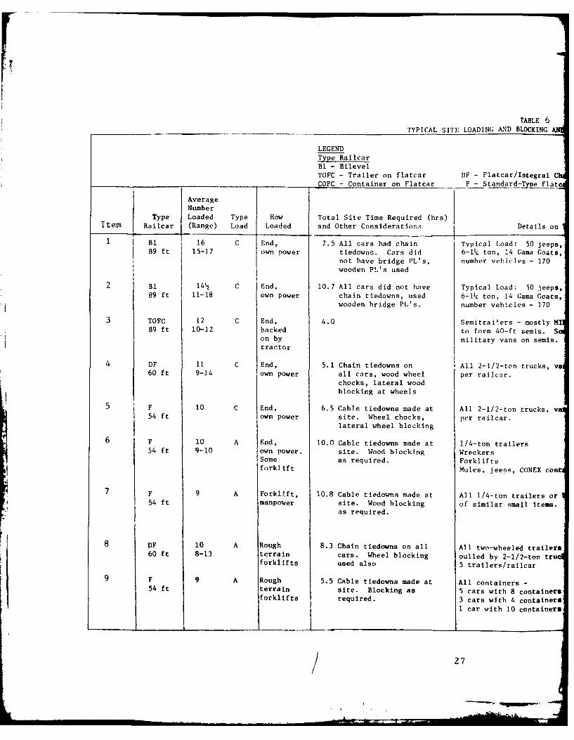
TABLE 6TYPICAL SITE LOADING AND BLOCKING
LEGENDType RailcarBl - Bilevel
TOFC - Trailer on flatcar DF - Flatcar/Integral CCOFC - Container on Flatcar F - Standard-TypeFlt
AverageNumber
Type Loaded Type How Total Site Time Required (hrs)Item Railcar (Range) Load Loaded and Other Considerations Details on
B1 16 C End, 7.5 All cars had chain Typical Load: 50 jeeps,89 ft 15-17 own power tiedowns. Cars did 6-I4 ton, 14 Gama Goats,
not have bridge PL's, number vehicles - 170wooden PL's used
2 BI 14 C End, 10.7 All cars did not have Typical Load: 50 jeeps,89 ft 11-18 own power chain tiedowns, used 6-14 ton, 14 Gama Goats,
wooden bridge PL's. number vehicles - 170
3 TOFC 12 C End, 4.0 Semitrailers - mostly M89 ft 10-12 backed to form 40-ft semis. S
on by military vans on semis.tractor
4 DF 11 C End, 5.1 Chain tiedowns on All 2-1/2-ton trucks, va60 ft 9-14 own power all cars, wood wheel per railcar.
chocks, lateral woodblocking at wheels
5 F 10 C End, 6.5 Cable tiedowns made at All 2-1/2-ton trucks, v54 ft own power site. Wheel chocks, per railcar.
lateral wheel blocking
6 F 10 A End, 10.0 Cable tiedowns made at 1/4-ton trailers54 ft 9-10 own power, site. Wood blocking Wreckers
Some as required. Forkliftsforklift Mules, jeeps, CONEX con
7 F 9 A Forklift, 10.8 Cable tiedowns made at All 1/4-ton trailers or54 ft manpower site. Wood blocking of similar small items.
as required.
8 DF 10 A Rough 8.3 Chain tiedowns on all All two-wheeled trailers
60 ft 8-13 terrain cars. Wheel blocking pulled by 2-1/2-ton truforklifts used also 5 trailers/railcar
9 F 9 A Rough 5.5 Cable tiedowns made at All containers -54 ft terrain site. Blocking as 5 cars with 8 containers
forklifts required. 3 cars with 4 containers
I car with 10 containers
_ _27 ____.____
/ 27
--

6AND BRACING TIMES (TOTAL)
Type Load
A - Administrativeal Chain Tledowns C - CircusFlatc.ir
Le on Type Load Manpower Typical Problems
jeeps, 15-3/4-ton trucks, 1 -2 No bridge PL's on cars had to use wooden PL's.;oats, each level, total men per Man has to walk to front of vehicle as guide
L70 vehicle and to straighten bridge PL's. Delays if allvehicles not at site at loading time.
jeeps, 15-3/4-ton trucks, 1 -2 Same as above; and, missing tiedowns; cable;oats, each level, total men per tiedowns had to be fabricated and used.
L70 vehicle (Storm, rain not included in total time)
tly MILVAN married together 6-8 Some older cars have trailer hitches whichi. Some 20-ft semis and man crew have to be "pulled-up" into position by a
Mis. Two per TOFC car. cable attached to the tractor.
ta, various kinds, two 10 men Noneper
railcar
ka, various kinds, two 10 men None
perrailcar
10 men Improper installation of tiedowns and
per blocking. Large number of small items,
railcar 1/4-ton trailer slow the installation of
I containers blocking since work has to proceed from oneend of railcar to the other.
'a or high percentage 10 men Improper installation of tiedowns and
eus. per blocking. Large number of small items,
rail car 1/4-ton trailer slow the installation ofblocking since work has to proceed from oneend of railcar to the other.
tilers (various types 10 men None noted
trucks) perrailcar
10 men None noted
iners each. per
iners ea, h. railcar
ilners eat h.
.P. •

for TOFG cars was 4 hours. Administrative loads,which require relatively longer times and more effort,are illustrated in figures 11 and 121/'. This type ofload required a total site time of 10 to 11 hours. Ingeneral, administrative moves should be planned fordaylight hours, leaving night hours available for finish-ing up sites that started late or were slowed by problemsand railcar switching. This type of planning allowsenough flexibility to resolve problems and complete theoperation on schedule. For mobilization moves, sitetime to load and secure equipment on a string of railcarsshould be accomplished in 5-1/2 to 7 hours, and foradministrative moves, in 4 to 11 hours (table 6, items3 and 7).
The time/motion studies conducted during theREFORGER 76 exercise (an administrative move)resulted in the accumulation of valuable information forplanning future station outloading operations and isincluded in tables 3 and 6. It should be noted that timesrequired to load are relatively minor as compared withtimes required to secure the equipment. As an example,a jeep can drive across an 89-foot-long bilevel car in1 minute, and a forklift truck can load a container in 2minutes 12 seconds. So, loading times are not theproblem. Also, as soon as the first vehicle is in posi-tion, several simultaneous operations are in effect- -
loading, blocking, and tieing down.
Thus, for future planning, site times should be used asa general rule: 5-1/2 to 7 hours for a mobilizationmove, and 4 to 11 hours for an administrative move.The 5-1/2-hour minimum for a mobilization move isbased on the assumption that only standard-type railcars
r. are available. The 4-hour minimum for an administra-
tive move carries the assumption that there is time to
4/ Administrative load- -equipment to be loaded (wheeled or otherwise) isplaced on the car so as to achieve maximum utilization of floor space;it may be stacked; cost is important. Both types of loads, circus andadministrative, may be used in either a mobilization or an administra-tive move depending upon the type of equipment to be moved. An ex-ample is item 9 in a mobilization move, item 5 in an administrativemove.
29

Figure 10. Lower level of bilevel cars loaded with jeeps, gama
goats, 3/4-ton trucks, and 1-1/4-ton trucks.
Figure 11. Administrative loading, mules.
plan and assemble the most appropriate type of railcars
for the equipment to be moved. The 4 hours, in this
instance, was the average time required to load and
secure semitrailers and vans on a string of twelve89-foot-long TOFC cars.
30
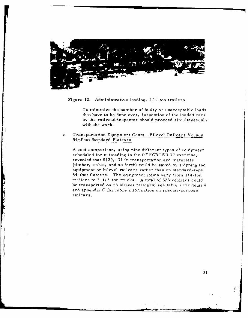
Figure 12. Administrative loading, 1/4-ton trailers.
To minimize the number of faulty or unacceptable loadsthat have to be done over, inspection of the loaded carsby the railroad inspector should proceed simultaneouslywith the work.
c. Transportation Equipment Costs--Bilevel Railcars Versus54-Foot Standard Flatcars
A cost comparison, using nine different types of equipmentscheduled for outloading in the REFORGER 77 exercise,revealed that $129,431 in transportation and materials(timber, cable, and so forth) could be saved by shipping theequipment on bilevel railcars rather than on standard-type54-foot flatcars. The equipment items vary from 1/4-tontrailers to 2-1/2-ton trucks. A total of 623 vehicles couldbe transported on 55 bilevel railcars; see table 7 for detailsand appendix C for more information on special-purposerailcars.
31

TABLE 7COST COMPARISON, BILEVELS VERS
Column Number 1 2 3 4 5 6 7
Quantity QuanItem Model Weight Height Length to be on 5No. Vehicle Type Number (lbs) (in.) (in.) Shipped Rail-
1 2-1/2-Ton Truck M35A2 13,360 80.8 264.8 1101 22 Gama Goat, 1-1/4-Ton M561 7,480 71.9 231.1 27- 23 M105A2 1-1/2-Ton Trailer M105A2 2,670 82.0 166.0 113 34 1/4-Ton Trailer M416 580 44.0 108.5 136 15 400-Gal Water Trailer M149A1 2,530 80.6 161.4 20 46 1-1/4-Ton Truck M880 4,695 73.5 218.5 11 27 3/4-Ton Trailer MI01 1,350 50.0 147.0 88 1/4-Ton Truck M151 2,350 52.5 131.5 1809 1-1/4-Ton Como Truck M884 4,648 67.5 218.5 18 2
Total 623
SUMMARY
Total cost to ship the 9 different items (623 vehicles) by 54-foot-long standard flatcars, ColTotal cost to ship the 9 different items (623 vehicles) by 89-foot-long bilevel flatcars, ColSavings in transportation costs if shipped by bilevel flats (Column 10-- Column 14)Additional costs of blocking and bracing materials if shipped by 54-foot standard flatcarsTotal savings if these nine items shipped by bilevel versus 54-foot flatcar
1/Excess vehicles shipped on other railcars that are not completely utilized.2/Estimated average additional costs of blocking and bracing materials per vehicle.
33

TABLE 7
ILEVELS VERSUS 54-FOOT FLATCARS
7 8 9 10 11 12 13 14
(8 x 9) (12 x 13)
tity Quantity No. of Trans Quantity No. of Trans
be on 54-ft 54-ft Cars Cost for on 89-ft Bilevels Cost for
ped Railcar Dollars Required Item Bilevel Dollars Required Item
o 2 2,413 55 132,715 6 7,238 18 130,284
7- 2 2,167 13 28,171 8 5,402 4 21,608
3 3 2,167 37 80,179 12 3,612 9 32,508
6 10 2,167 14 30,338 36 3,612 4 25,284
4 2,167 5 10,835 12 3,612 2 7,224
1 2 2,167 5 10,835 8 3,612 2 7,224
8 4 2,167 2 4,334 12 3,612 1 3,612
7 2,167 25 54,175 14 3,612 13 46,956
2 2,167 9 19,503 8 3,612 2 4,334
371,085 55 279,034
tcars, Column 10 $371,085cars, Column 14 279,034
$ 92,051tcars 37,380 ($60- / x 623)
$129,431

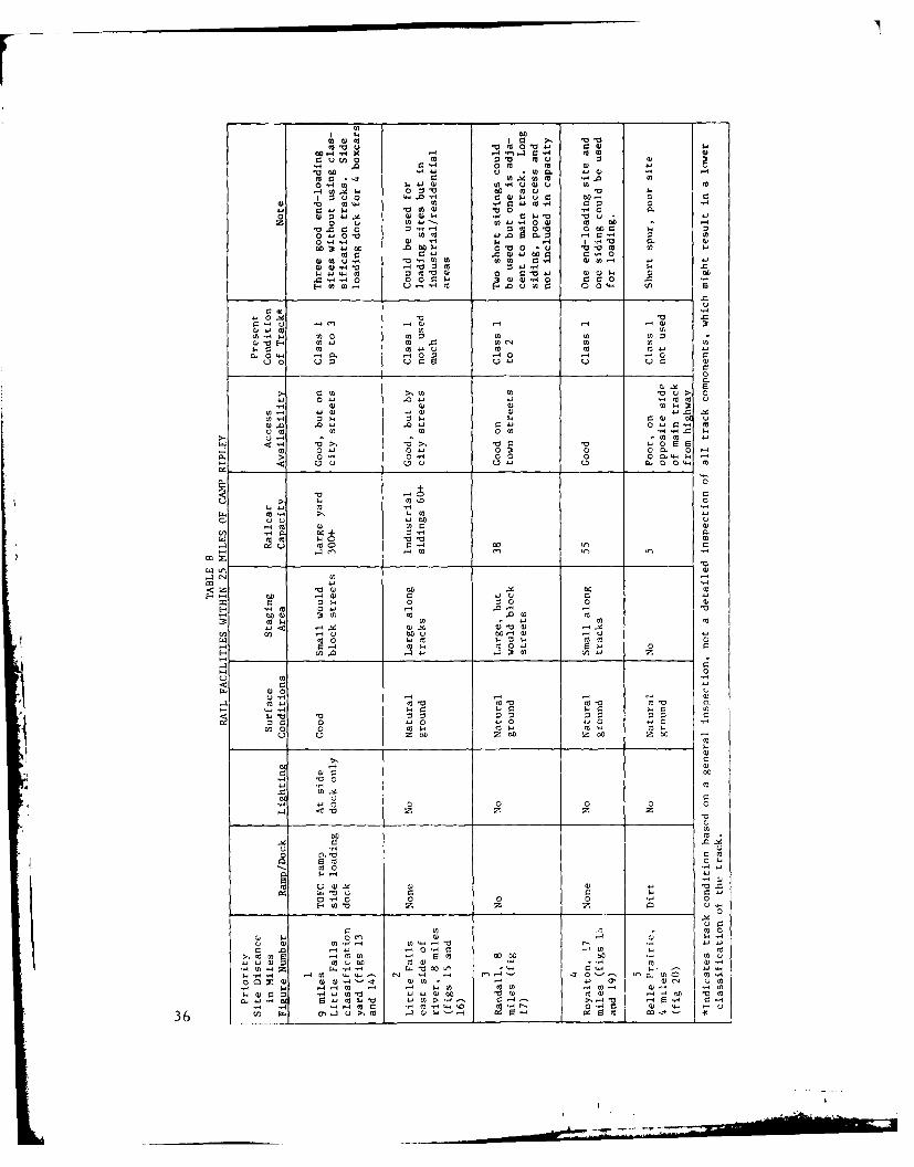
III. ANALYSIS OF COMMERCIAL RAIL FACILITIES WITHIN THE CAMP RIPLEY AREA
The present facilities at Camp Ripley are not adequate to handle the peakmobilization requirement for the installation. All commercial rail facili-ties within 25 miles of Camp Ripley were surveyed to determine the feasi-bility of their use during full-scale rail outloading operations. Many factorswere considered in making the determination, including:
a. Road access to the facility.
b. Type of facility available- -ramps, lighting.
C. Equipment staging and queuing areas.
d. Railcar storage and loading capacities.
e. Track and facility maintenance conditions.
f. Main line activity levels.
g. Added expense of using commercial facilities.
h. Security problems.
The best sites to handle the shortfall are along the BNRR main line trackat the entrance to Camp Ripley. These are better than the other facilitiesbecause: they are close, security will be less of a problem, the main linetrack north of Camp Ripley is under study by the BNRR for abandonment,and most of the other sites will be needed for railcar storage. Since thesesites are adjacent to Camp Ripley, and are included in the recommendedplan, they are described in table 2. Other alternate sites are describedin table 8 and figures 13 through 20.
Little Falls Clas sification Yard
This yard (figs 13 and 14) could be used as an alternate loading site.There are three good end-loading sites, one with a substantial timber endramp and a side-loading dock suitable for four boxcars. Access is goodfrom the south (Broadway) and west side at the'TOFC ramp. The capacityof this yard makes it suitable for accumulating and staging empty railcarsto support rail operations at Camp Ripley; this should be its function in anoutloading ope ration.
35
00
wo0 m >. aw00 to '0 " OW .
u 0' u 0
00 ~ ~ 0 ca~ 0 u0 *-.
5-pJ v..C U 0 40.5 V0m'a 0 0 0 5
z 0 0 u -. 4 U) U) 0 On..- 0C C: 0 z 0 04 o~ co 0: w
0" 4"5 000 'a0 In. 0 r0 14. 1-4- .,,4r 00 *4
0o Uo 04-o. 0 0 0 v m to'000 c,4' Q) 00 C 0 c .0 .0
.140~ to to. 0. -4H a, (0w ) 4 .0 .04 a5 140 w0''0 0
m0 04 -V.0 C6.4
44.0 0044 0 0'04"4 0 C45-
4"M V0'0 .
0-u En, 'A0-.4 40
0 :3
u 10
.4. r 05-a, 0 0 0 4-0 0 CL 0>,- 05 04 -0000 CL 0$
0. .04 .04 04. 40~ 01
>4- . '4 4 10>40'
0. cu"400 00.-5
00 0
'4 U u0 r-4 00I
414 0-4"4z~~ 01 0:
E0 .,- cc 0,~ 41 .-
u44, 0
00
t)0 0400
-4 40 4 9: p~ w
05- " 4" 0
be- 004 00- 0 m
5-. ~~~ ~~40-4 -~ 14
00
0 0
0 rL
5-m 00
'0 0 00 00 0 0
4
-4 0 a
.0 V Wq)a D .
m a0 00 Ac (364 a,4 03 0 0 a) m c
-~ ~'0 0MEMO"
*. " . :;, N_ ,
Figure 13. Little Falls, classification yard, northerly view from
Broadway. Two of three possible end-loading sitesin foreground.
F i,, re 14. Little Falls, v.,est sidc of cLssification v rd.
TOFC ramp (foreground) and side-loadingdock for four boxcars (center).
37

ar
Figure 15. Little Falls, east side of river, northerly view
from Broadway.
Figure 16. Little Falls, east side of river, southerly view
from Broadway.
38
* .t
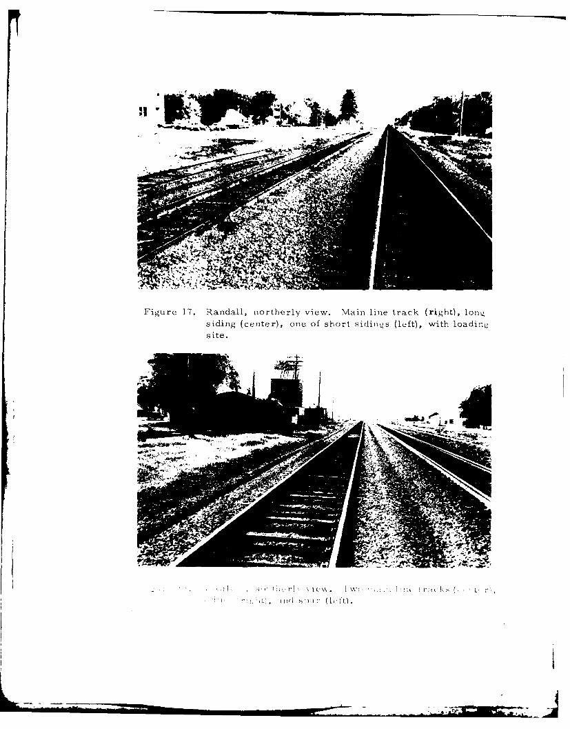
Figure 17. Randall, northerly view. Main line track (ri.ght), Iomn,
siding (center), one of short sidings (left), with loadin~g
site.
IEj
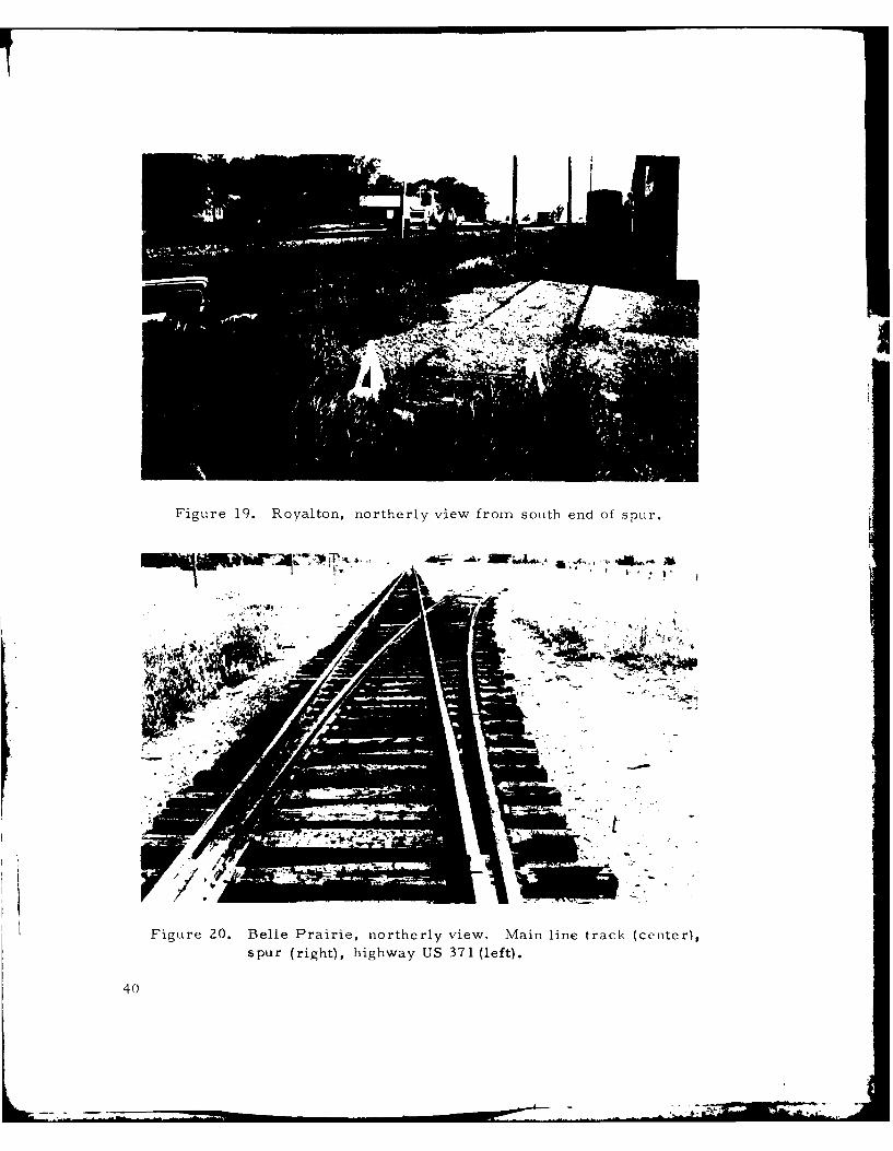
Figure 19. Royalton, northerly view from south end of spur.
Figure 20. Belle Prairie, northerly view, Main line track (ceiter),spur (right), highway US 371 (left).
40

Little Falls, East Side of River
This site is in a light industrial/residential area and could be used as anoutloading site since access is good and there are large open areas alongthe tracks (figs 15 and 16). The capacity of the trackage makes it suitablefor railcar storage in support of Camp Ripley.
Randall
This site has one long siding/passing track and two short sidings. Accessis good, and there is a possible loading site along one siding (fig 17).
Royalton
There are two possible loading sites, a spur and a siding; access to bothis good (figs 18 and 19).
Belle Pairie
This is a very poor loading site due to its small capacity and to itslocation (fig 20).
-I
41[
IV. SPECIAL EQUIPMENT FOR EXPEDITING THE OUTLOADINGOF MILVANS
A large supply of trailer-on-flatcar railcars is usually in the system, andcontainer-on-flatcar railcars may be available. These cars should beused to transport semitrailers and MILVANs. If COFC or TOFC flatcarsare not available, some blocking and bracing time and expense can besaved by using bulkhead flatcars for transporting MILVANs. See appendixC for additional information.
42
V. ANALYSIS OF MOTOR SYSTEM OUTLOADING CAPABILITY
A. GENERAL
Major highway access to Camp Ripley is provided by US Route 371,
which parallels the east boundary of the installation. The internalroad network within Camp Ripley is capable of handling all types ofhighway vehicles along its major arteries. Neither access to thehighway system nor the system itself restrains motor outloading capa-bility or movement of roadable military vehicles.
B. MOTOR LOADING FACILITIES
Basically two types of motor vehicle, that is, flatbed and van semi-
trailer, would be required to meet the motor outloading needs ofCamp Ripley. A description of the loading facilities aesociated with
each vehicle type follows:
1. Loading Ramps
A survey of facilities that might have end-loading ramps to load
vehicles onto commercial flatbed semitrailers revealed that thereare two such ramps with five outloading positions that could be
used concurrently with a rail outloading operation (table 9 and figs21 and 22). As a separate operation, without rail outloading,
there are 6 ramps with 11 outloading positions, including the ex-isting rail ramp.
2. Loading Platforms/Docks
The other type of motor outloading facility is the loading platformfrom which van semitrailers are loaded. It is the medium, alongwith the forklift, that is used to transfer cargo from truck totruck, truck to waiehouse, and vice versa. The only warehouseequipped with a side-loading dock is illustrated in figure 5.
C. FLATBED SEMITRAILER OUTLOADING
The loading procedure could be as follows: A vehicle is driven up the
ramp and onto the waiting semitrailer, temporary chocks are placed,and the loaded truck is driven slowly away from the ramp to a desig-nated location where it is secured with tiedown chains. The next
43

TABLE 9VEHICLE END-LOADING RAMPS AND DOCKS
and Fgure i Locat ion of Ram _ Condition Staging Access Remarks
_____ Cncrrent With Rail 0 eraions -
1 Ramp, Libby Ave Concrete Sandy large Good New concrete, three3 Positions near Bldg soil di ffrent levels(fig 21) U-61 U-hi for height of truck
1 Ramp, Near Earth Natural Large Good2 Positions sanitary fill timber soil -
(fig 22) _ ____
Without Rail Operations
5 above See above -i Ramp End of Concrete Good, Large Good Rail end-loadingI Position south spur paved ramp(fig 3) track
I Ramp U-14 Concrete Good Large Good Rail side-loading4 Positions on south and earth ramp for south(fig 4) spur track spur, could be
used for end-loading
trucks
1 Ramp South end Timber Good Large Good Rail side-loading1 Position of Bldg side ramp ramp, could be used(fig 5) U-11 for rail for end-loading
L L trucks
Van loading - only one warehouse has a loading dock and it is for one position only, adjacent to the south
spur at Bldg U-11.
Figure 21. Concrete end-loading ramp, three positions,left side of figure.
44
• I

Figure 22. Earth/timber ramps, two positions.
semitrailer is backed up to the ramp, and the procedure is repeated.Under this procedure, the ramp is not occupied while loaded vehicles
are being secured. Using a conservative 60 minutes for each cycle,I semitrailer could be loaded per hour per ramp, or 10 vehicles perramp per 10-hour shift. In most cases, 60 minutes would not be re-
quired.
1. Concurrent With Rail Operations
There are two ramps with five outloading positions that could be
used while rail operations are in progress. Using a 60-minutecycle, per ramp, a 10-hour workday could produce 50 semitrailerloads, for daylight operation only. This does not include expedientmeans, such as excavating sloping ditches into which semitrailers
could be backed for loading; nor use of 6, 000-pound commercialforklift trucks, if they are not assigned to railcar loading; northe use of mobile cranes. Numerous possibilities exist for in-
creasing motor outloading facilities.
2. Without Rail Operations
If rail operations are not in progress, there are o loading rampswith 11 outloading positions to load commercial semitrailers. At60 minutes per cycle per ramp, 110 semitrailers could be out-loaded in a 10-hour workday. However, the possibility of obtain-ing 110 commercial semitrailers locally on any day seems highlyunlikely. Therefore any constraint on Camp Ripley's semitrailer
outloading capability is not the lack of facilities, but the lack ofsemitrailers.
45
D. VAN SEMITRAILER OUTLOADING
Since Camp Ripley has only one side-loading dock position, vans willhave to be loaded by expedient means; that is, the forklifts place thecargo at the rear of the truck cargo bed and the cargo is moved intofinal position by hand labor. Using this procedure and the eight 2, 000-to 6, 000-pound-capacity forklifts, 32 vans could be loaded in a 10-hour period.
46
VI. CONCLUSIONS
1. The BNRR currently plans to abandon their main line track north of
Camp Ripley Junction; 6, 400 feet of this main line track, north of thenorth switch of the Camp Ripley wye, is needed for mobilization re-
quirements. (Arrangements have been completed by MTMC and BNRR
to retain the needed trackage. )
2. Most of Camp Ripley's railroad trackage is classified as Class 1,
according to federal track safety standards. Minor maintenance ondeficient sections would upgrade all trackage to a Class 2 condition.
3. Other constraints limiting Camp Ripley's rail outloading capability
are a shortage of blocking and bracing materials, small handtools,
and bridgeplates; insufficient trained blocking and bracing crews; and
a lack of outloading plans.
4. End-loading ramps are needed for the three additional identified load-ing sites, and side-loading docks will be needed for seven boxcars per
day.
5. After the deficiencies noted above are corrected and upon receipt of
sufficient railcars to permit full-scale outloading, Camp Ripley could
outload 106 railcars per 24-hour period. However, to meet the totalrequirement, 100 railcars will need to be outloaded per 24-hour per-
iod on the BNRR main line at Camp Ripley.
6. Empty railcars (dedicated train lengths) destined for Camp Ripley
should be positioned in train-loading sequence in Little Falls.
7. Camp Ripley's transportation personnel should coordinate planning ofimpending outloading operations with the BNRR representatives at the
earliest possible date.
8. For administrative-type moves, when leadtime is plentiful and costsmust be considered, special-purpose railcars (such as bilevel auto-
racks, trailer-on-flatcar (TOFC), and container-on-flatcar (COFQ)
are more cost-effective than the standard types and should be used
to the extent they are available.
9. For mobilization moves, when time is more critical than cost, the use
of special-purpose railcars may not be possible because of the short
leadtirne and relatively short supply of these high-demand cars.
47
10. Motor outloading is not a good alternative to rail because Camp Ripleyis more than 800 miles from any POE.
11. For concurrent rail and motor operations, 50 flatbed and 32 van semi-trailers could be loaded per 10-hour day (for daylight operations only),and for separate operations, 110 flatbed and 32 van semnitrailers couldbe loaded during the same period. This capability exceeds the prob-able available supply of semitrailers.
12. The maximum curvature of the railroad tracks is less than 12 degrees.Consequently, any known length of railcar car be used on the instal-lation.
48
VII. RECOMMENDATIONS
1. Use the BNRR main line track near the entrance to Camp Ripley tooutload the mobilization shortfall.
2. Undertake those items listed in section II, paragraph D4, "PhysicalImprovements and Additions. " These improvements will provide arail system capability of 206 railcars per 24-hour day as well as an
effective rail system.
3. Prepare a detailed unit outloading plan, using the simulation in ap-pendix B as an example, specifying unit assignments at loadout sitesand movement functions.
4. Coordinate rail outloading plans with BNRR representatives at theearliest possible date.
5. Initiate a rail facility maintenance program to insure an effectiverail system.
6. Provide advance training for blocking and bracing crews.
7. Station road guards at all railroad crossings during outloading opera-tions, and provide all train crewmen with walkie-talkies to insure asafer and more efficient operation.
8. Keep abreast of BNRR railroad maintenance plans on the main linetrackage to Little Falls.
9. Use special-purpose railcars (such as bilevel autoracks for smallvehicles, TOFC cars for semitrailers and vans, and COFC cars forMILVANs) for administrative-type moves, and, as available, formobilization moves.
10. Provide warehousing for blocking and bracing materials and small-tool supplies.
11. Coordinate with MTMC any removal of railroad track that is includedin the mobilization outloading plan.
12. Construct any new track with a maximum curvature of 12 degrees.
49
AI
APPENDIX A
TRACK SAFETY STANDARDS-
PART 213- TRACK SAFETY 213.121 Rail joints.STANDARDS 213.123 Tie plates.
213.125 Rail anchoringSubpart A -General 213.127 Track spikes.
See. 213.129 Track shims.213.1 Scope of part. 213.131 Planks used in shimming.213.3 Application. 213.133 Turnouts and track crossings generally.213.5 Responsibility of track owners. 213.135 Switches.213.7 Designation of qualified persons to 213.137 Frogs.
supervise certain renewals and inspect 213.139 Spring rail frogs.track. 213.141 Self-guarded frogs.
213.9 Classes of track: operating speed limits 213.143 Frog guard rails and guard faces; gage.213.11 Restoration or renewal of track under Subpart E-Track Appliances and Track-Related
traffic conditions. Devices213.13 Measuring track not under load. 213.201 Scope.213.15 Civil penalty. 213.205 Derails.213.17 Exemptions 213.207 Switch heaters.
Subpart B- Roadbed Subpart F- Inspection
213.33 Drainae. 213.231 Scope.213.37 Veigeio. 2 13.233 Track inspections.213.7 Veetaton.2 13.235 Switch and track crossings inspections.
Subpart C -Track Geometry 213.237 Inspection of rail.213.51 Scope. 213.239 Special inspections.213.53 Gage. 213.241 Inspection records.
APPENDIX A - MAXIMUM ALLIOW ABLVEOPERATING
Sec.SPEEDS~ FOR CUR VED) TRACK
213.55 Alinement. AUTHORITY: The provisions of this Part 213
213.57 Curves; elevation and speed limitations. issued under sections 202 and 209. S4 Stat. 971.
213.59 Elevation of curved track: runoff. 975: 45 U.S.C. 431 and 438 and 1.49(n) of the
213.61 Curve data for Classes 4 through 6 track. Regulations of the office of the Secretary of
213.63 Track surface. Transportation: 49 CFR 1.49in).
Subpart 0 -Track Structure SOURCE: The provisions of this Part 213 ap-
213.101 Scope. pear at 34i FRH. 20336. Oct. 20. 1971. unless other-
213.103 Ballast; general. wise noted.
213.105 Ballast: disturbed track. Subpart A -General213.109 Crossties.213.113 Defective rails. 21:3.1 Scope of part.213.115 Rail end mismatch Ti atpecie nta iiu213.117 Rail end batter. Ti atpecie nta iiu
213.119 Continuous welded rail, safety requirements for railroad track
il.Extracted from Title 49, Transportation, Parts 200 to 999, pp 8-19,Code of Federal Regulations, 1973.
50
that is part of the general railroad svs- (4) A precise identification of thetern of transportation. The requiremei.its track;prescribed in this part apply to specific (5) A statement as to the competencetrack conditions existing in isolation, and ability of the assignee to carry outTherefore, a combination of track con- the duties of the track owner under thisditions, none of which individually part; andamounts to a deviation from the require- (6) A statement signed by the assigneements ini this part, may require remedial acknowledging the assignment to him ofaction to provide for safe operations over responsibility for purposes of compliancethat track. with this part.
§ 2133 Aplicaion.(c) If the Administrator is satisfied§ 2133 Aplicaionthat the assignee is competent and able(a) Except as provided in paragraphs to carry out the duties and responsibil-
(b) and (c) of this section, this part ities of the track owner under this part,applies to all standard gage track in the he may grant the petition subject to anygeneral railroad system of transporta- conditions he deems necessary. If thetion. Administrator grants a petition under
(b) This part does not apply to track- this section, he shall so notify the owner(1) Located inside an installation and the assignee. After the Adminis-
which is not part of the general railroad trator grants a petition, he may hold thesystem of transportation; or track owner or the assignee or both
(2) Used exclusively for rapid transit, responsible for compliance with this partcommuter, or other short-haul passen- and subject to penalties under § 213.15.ger service in a metropolitan or subur- § 213.7 Designation of qualified personsban area. t ue~ecranrnwl n n(c) Until October 16, 1972, Subparts tospetraicekareeas n nA, B, D (except § 213.109), E, and F of pctakthis part do not apply to track con- (a) Each track owner to which thisstructed or under construction before part applies shall designate qualifiedOctober 15, 1971. Until October 16, 1973, persons to supervise restorations andSubpart C and § 213.109 of Subpart D do renewals of track under traffic condi-not apply to track constructed or under tions. Each person designated mustconstruction before October 15, 1971. have-
(1) At least.-§213.5 Responsibility of track owners. (i) One year of supervisory experience(a) Any owner of track to which this in railroad track maintenance; or
part applies who knows or has notice (ii) A combination of supervisory ex-that the track does not comply with the perience in track maintenance and train-requirements of this part, shall- ing from a course in track maintenance
(1) Bring the track into compliance; or from a college level educational pro-or gram related to track maintenance;
(2) Halt operations over that track. (2) Demonstrated to the owner that(b) If an owner of track to which this he-
part applies ass4 gns responsibility for the (i Knows and understands the re-track to another person (by lease or quirements of this part;otherwise), any party to that assignment (ii) Can detect deviations from thosemay petition the Federal Railroad Ad- requirements; andministrator to recognize the person to (iii) Can prescribe appropriate re-whom that responsibility is assigned for medial action to correct or safely com-purposes of compliance with this part. pensate for those deviations; andEach petition must be in writing and (3) Written authorization from theinclude the following- track owner to prescribe remedial ac-
(1) The name and address of the track tions to correct or safely compensate forowner; deviations from the requirements in this
(2) The name and address of the per- part.son to whom responsibility is assigned (b) Each track owner to which this(assignee) ; part applies shall designate qualified
(3) A statement of the exact relation- persons to inspect track for defects. Eachship between the track owner and the person designated must have-assignee; (1) At least-
51

Q) One year of experience in railroad (b) If a segment of track does nottrack inspection" or meet all of the requirements for its in-
(ii) A comt .l'iation of experience in tended class, it is reclassified to the nexttrack inspec'ion and training from a lowest class of track for which it doescourse in track inspection or from a col- meet all of the requirements of this part.lege level educational program related to However, if it does not at least meet thetrack inspection; requirements for class 1 track, no opera-
(2) Demonstrated to the owner that tions may be conducted over that seg-he- rnent except as provided in § 213.11.
(1) Knows and understands the re- (c) Maximum operating speed mayquirements of this part: not exceed 110 m.p.h. without prior ap-
(ii) Can detect deviations from those I)roval of the Federal Railroad Adininis-requirements; and trator. Petitions for approval must be
(iii) Can prescribe appropriate re- filed in the manner and contain the in-medial action to correct or safely com- formation required by § 211.11 of thispensate for those deviations; and chapter. Each petition must provide suf-
(3) Written authorization from the ficient information concerning the per-track owner to prescribe remedial ac- formance characteristics of the track,tions to correct or safely Lompensate for signaling, grade crossing protection,deviations from the requirements of this trespasser control where appropriate,part, pending review by a qualified per- and equipment involved and also con-son designated under paragraph (a) of cerning maintenance and Inspectionthis section. practices and procedures to be followed,
(c) With respect to designations under to establish that the proposed speed canparagraphs (a) and (b) of this section, be sustained in safety.each track owner must maintain written [36 FR 20336, Oct. 20, 1971, as amended at
records of- 38 FR 875, Jan. 5, 1973: 38 FR 23405. Aug. 30,(1) Each designation in effect; 19731(2) The basis for each designatioi., § 213.11 Restoration or renewal of track
and under traffic conditions.(3) Track inspections made by each If, during a period of restoration or
designated qualified person as requiredby § 213.241. renewal, track is under traffic conditions
and does not meet all of the require-These records must be kept available for ments prescribed in this part, the workinspection or copying by the Federal and operations on the track must beRailroad Administrator during regular under the continuous supervision of abusiness hours. per deigntind er a[36 FR 20336, Oct. 20, 1971, as amended at person designated under § 213.7(a).38 FR 875, Jan. 5, 1973[ § 213.13 Measuring track not tunder
§ 213.9 Classes of track: operating speed load.limits. When unloaded track Is measured to
(a) Except as provided in paragraphs determine compliance with requirements(b) and (c) of this section and §§ 213.57 of this part, the amount of rail move-(b), 213.59(a), 213.105, 213.113 (a) and ment, if any, that occurs while the track(b), and 213.137 (b) and (c), the follow- is loaded must be added to the measure-ing maximum allowable operating speeds ment of the unloaded track.apply: 138 FR 875, Jan. 5, 19731
[In miles per hour] § 213.15 Civil penalty.
The maximum The maximum (a) Any owner of track to which thisOver track that meets allowable allowahlh. part applies, or any person held by theall of the requirem lits operating operatingprescribed in this part spiid for speed for Federal Railroad Administrator to be re-
for- freight trains eaiss.,tgr sponsible under § 213.5(c), who violatesIs-- trains any requirement prescribed In this part
Class I track ------ -- 0 i5 is subject to a civil penalty of at leastClass 2 track ........... 25 30Class 3track ----- 40 co $250 but not more than $2,500.Class 4 track --------- 60 90 (b) For the purpose of this section,Class 5 track ........... No AClass6track ----------- 110 110 each day a violation persists shall be
treated as a separate offense.
52
Exemptions. rails in a plane five-eighths of an inch
(a) Any owner cf track to which this below the top of the rail head.part applies may petition the Federal (b) Gage must be within the limitsRailroad Administrator for exemption prescribed in the following table:from any or all requirements prescribedin this part. The gage of tangent The gage of curved
(b) Each De-,'tion for exemption under Class of track must be-. track must be-this section must be filed in the manner track
At But not At But notand contain the information required by least- more than- least- more than-§ 211.11 of this chapter.
(c) If the Administrator finds thatan exemption is in the public interest and ........ 4' S" 4' 9!" 4' 8" 4' 9"
-ad 3.- -- 4' 8" 4' 9k" 4' 8" 4' 9Y,"is consistent with railroad safety, he may 4 .......... Vb" 4' 9" 4'8" 4' k2J"grant the exemption subject to any con- ---------- 4' " 4' 9" 4' 8" 4' 9W'ditlons he deems necessary. Notice of 6 ---------- 4' " 4' 8b" 4'8" 4'9"
each exemption granted is published in --- - -
the FEDERAL REGISTER together with a § 213.55 Alinement.s~atement of the reasons therefor. Alinement may not deviate from uni-
Subpart B-Roadbed forinity more than the amount pre-
§ 213.31 Scope. scribed in the following table:
This subpart prescribes minimum re-quirements for roadbed and areas im- Tangent track Curved trackmediately adjacent to roadbed.
The deviation of The dnviation of§ 213.33 Drainage. ('lass ef track the nili-offw,t the nli-orL!nafe
from 6- _-foot lnl from 62.foot chord 2Each drainage or other water carrying may not be more may not be more
facility under or Immediately adjacent than- than-
to the roadbed must be maintained andkept free of obstruction, to accommodate I --------------- 6" Y,expected water flow for the area con- 2 ------------------ 3" 3"
cerned. 4-------------------l's"-cerned. 4-------------------1,' 1W',5 ............... A" a
§ 213.37 Vegetation. a ------------------- 'Vegetation on railroad property which
Is on or immediately adjacent to roadbed I The, .nids of the line nost be at points on the gagemust be controlled so that it does not- sile of ow i., rail. fiv- -Ih'iths of an inch blow the top
(a eco afire hazard to track- of the rl!hal. Eitier rail may be lused as the line rail,(a) Become a horvrr. il, slur. rail rust be uged for the full length ofcarrying structures; that tsngthd 'a-am,'nt of track.
b Th,, Ob as , tho, chord must I.' at. points on the gage(b) Obstruct visibility of railroad signs id, of tht- ,ruter 'all, five-eighths of an Inch below theand signals, top of the rallhoad.
(c) Interfere with railroad employees § 213.57 Curves; elevation and speedperforming normal trackside duties; limitations.
(d) Prevent proper functioning of sig-nal and communication lines; or (a) Except as provided in § 213.63,
(e) Prevent railroad employees from the outside rail of a curve may not bevisually inspecting moving equipment lower than the inside rail or have morefrom their normal duty stations, than 6 inches of elevation.
(b) The maximum allowable operat-Subpart C-Track Geometry ing speed for each curve is determined
§ 213.51 Scope. by the following formula:
This subpart prescribes requirements f E.+3for the gage, alinement, and surface of 0.0007dtrack, and the elevation of outer rails whereand speed limitations for curved track. V...=Maximum allowable operating speed§ 213.53 Gage. (miles per hour).
E.=Actual elevation of the outside rail(a) Gage is measured between the (inches).
heads of the rails at right angles to the d =Degree of curvature (degrees).
53
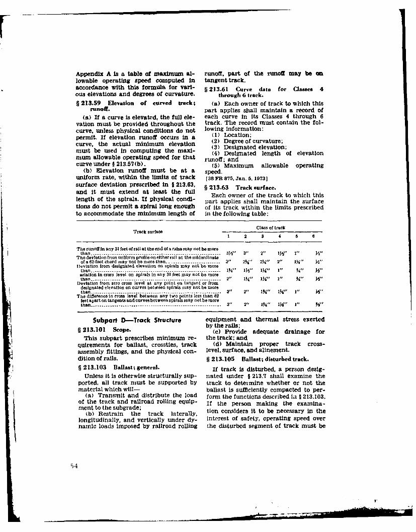
Appendix A Is a table of maximum al- runoff, part of the runoff may be onlowable operating speed computed in tangent track.accordance with this formula for vari- § 213.61 Curve data for Classes 4ous elevations and degrees of curvature. through 6 track.§ 213.59 Elevation of curved track; (a) Each owner of track to which this
runoff, part applies shall maintain a record of
(a) If a curve is elevated, the full ele- each curve in its Classes 4 through 6vation must be provided throughout the track. The record must contain the fol-curve, unless physical conditions do not lowing information:permit. If elevation runoff occurs in a (1) Location;curve, the actual minimum elevation (2) Degree of curvature;cuvt te u ald In ompin the(3) Designated elevation;must be used In computing the maxl- (4) Designated length of elevationmum allowable operating speed for that runoff; andcurve under § 213.57(b). (5) Maximum allowable operating
(b) Elevation runoff must be at a speed.uniform rate, within the limits of track 138 FR 875, Jan. 5, 1973]surface deviation prescribed In § 213.63, § 213.63 Track surface.and It must extend at least the full Each owner of the track to which thislength of the spirals. If physical condi- part applies shall maintain the surfacetions do not permit a spiral long enough of its track within the limits prescribedto accommodate the minimum length of in the following table:
Class of trackTrack surface1 2 3 4 5 a
The runoff In any 31 feet of rail at the end of a raise may not be morethan ------------------------------------------------ ----------- 3/21 3"1 2" 1,411 1" )/"
The deviation from uniform profile on either rail at the mddordinateof 62-foot chord may not be more than -------.--------------- 3" 2Y," 2Y" 2" l I/" Y"
Deviation from designated elevation on spirals may not be morethan -------------------------------- .-------------------.. .------- I" 1" 3." ,arlatioo in cross level on spirals in any 31 feet may not be morethan- ------------------------------------------ 2" 1J/Y" 1yl" 1" Y"1 "
Deviation from zero cross level at any point on tangent or from
designated elevation on curves between spirals may not be morethan ------------------------------------------------------------- 3" 2" 13y(" 131'" 1" A"
The difference in cross level between any two points less than 62feet apart on tangents and curves between spirals may not be morethan-------------------------- ------------------------- 3" 2" 0l" I 13ill" 4
Subpart D-Track Structure equipment and thermal stress exerted§ 213.101 Scope. by the rails;
(c) Provide adequate drainage forThis subpart prescribes minimum re- the track; and
quirements for ballast, crossties, track (d) Maintain proper track cross-assembly fittings, and the physical con- level, surface, and alinement.dition of rails. § 213.105 Ballast; disturbed track.
§ 213.103 Ballast; general. If track is disturbed, a person desig-Unless It is otherwise structurally sup- nated under § 213.7 shall examine the
ported, all track must be supported by track to determine whether or not thematerial which will- ballast is sufficiently compacted to per-
(a) Transmit and distribute the load form the functions described ia § 213.103.of the track and railroad rolling equip- If the person making the examina-ment to the subgrade;
(b) Restrain the track laterally, tion considers it to be necessary in thelongitudinally, and vertically under dy- interest of safety, operating speed overnamic loads imposed by railroad rolling the disturbed segment of track must be
54I
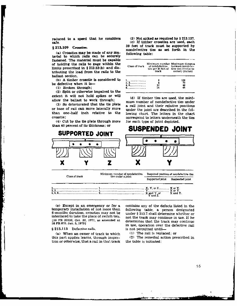
reduced to a speed that he considers (5) Not spiked as required by § 213.127.safe. (c) If timber crostes are used, each§ 213.109 Croeties. 39 feet of track must be supported by
nondefective ties as set forth In the(a) Crosstles may be made of any ma- following table:
terial to which rails can be securelyfastened. The material must be capableof holding the rails to gage within the Minimum number Maximum distance
Class of track of nondefective between nondeec-limits prescribed in I 213.53(b) and dis- ties Per 39 feet of tive ties (center to
tributing the load from the rails to the track center) (inches)
ballast section.(b) A timber crosstie Is considered to I ............... 5 100
be defective when it is- 2,3 -------------- 8 704,5---------------12 48(1) Broken through; --------------- - 14 48
(2) Split or otherwise impaired to theextent it will not hold spikes or will Wd If timber ties are used, the mini-allow the ballast to work through; mum number of nondefective ties under
(3) So deteriorated that the tie plate a rail joint and their relative positionsor base of rail can move laterally more under the joint are described in the fol-than one-half inch relative to the lowing chart. The letters in the chartcrosstie; correspond to letters underneath the ties
(4) Cut by the tie plate through more for each type of Joint depicted.than 40 percent of its thickness; or
SUPPORTED JOINT S
x Y z X YMinimum number of nondefective Required position of nondefective ties
Class of track ties under a jointSupported Joint Suspended Joint
1 .........----------------------------- X, Y, or Z ........ XorY.2,3 -------- - -- -------------- ------------- Y ................. XorY.4,5,6............................... 2 --------------........... ........ X and Y. or X and Y.Y and Z.
(e) Except in an emergency or for a contains any of the defects listed in thetemporary installation of not more than following table, a person designated6-months duration, crossties may not be under § 213.7 shall determine whether orinterlaced to take the place of switch ties. not the track may continue in use. If he(36 FR 20336, Oct. 20, 1971, as amended at determines that the track may continue38 FR 875, Jan. 5, 19731 in use, operation over the defective rail
§ 213.113 Defective rails, is not permitted until-
(a) When an owner of track to which (1) The rail is replaced; orthis part applies learns, through inspec- (2) The remedial action prescribed intion or otherwise, that a rail in thal track the table is initiated:
55
_L_

RZMZDmAL ACTION
Length of defect Percent of railhead If defective railDefeCt (inch) cross-sectioni area Is not replaced,
Defect weakened by defect take the remedialaction prescribed
More than But not Less than But not In note-more than less than
20 .............. B.rransverse fissure .................................................. 100 20 B.
100 A.20----------...BCompound fissure ................................................ 100 20 B.
Detail fracture -------------------------------------------- 2 100 A.Engneta un fracture ..------------------------------------- -20 - -...... C.Engine bun fracture.................................... ........... 100 20 D.Defective weld---------------------- ................-............. 100 A or E and H.Horizontal split head ------------------ 0 2 --------------------------- Hand F.2 4 --------------------- l- I and G.Vertical split heed---------------..4 ------ -------------- B.
I (Break out in ratlhea) --------------------- A.Split web .............................. 0 j4-------------- - H and F.P~pe fal ...... ... .... .... ... ..... 3 ........................... Ia d G
Piped~~ ~ ~ ~ rai........................A..................... I nB .Head web separation ................... 3 --------------------- ---------------- B.hed e spaaio---------(Break out In rallhead)_ ---------------- ------ A.
0 , -------------- H and F.Bolt hole crack ------- Y2 .......................... I and O.m ----- B.(Break iutn railhca-f ........... A.Broken base -------------------------- 0 6 --------- _---------------- E and 1.
6 ....... .................. -------------- (Replace rail).Ordinary break ------------------------.------------------.------------------------------------ A or E.Damaged rail ------------------------------------------- ......----------------------- _----- C.
NOT.:A Assign person dtesignated under §213.7 to visually supervise each operation over defective rail.II - Limit operating speed to 10 m.p.h. over defective rail.I - A pply Joint I:ars bolted only through the outermost hole.s to defect within 20 days after it is determined to
o'illnne the track it use. In the case of classes 3 through 6 '.rack, limit operating speed over defective rail to 30m..h. until angle bars are applied; thereafter, limit speed t0 50 m.p.h. or the.maximum allowable speed under§ 213.9 for time class of track concerned, whichever is lower.
1) Apply joint bars bolted only through the outermost holes to defect within 10 days after it is determined tocomtinue the track in use. Limit operating speed over defetive rail to 10 m.p.h. until angle bars are applied;then-after, limit sled to 50 m.p.h. or the maximum allowable speed under § 213.9 for the class of track concerned,whichever is lower.
E-Apply joint bars to defect and bolt in accordance with 1 213.121 (d) and (e).F-Inspeit rail 90 days after it is determined to continue the track In use.ti-Insect rtil 30 days after it Is determined to continue the track in use.I-Limit o-,rating speed over defective rail to 50 m.p.h, or the maximum allowable speed under § 213.9 for the
class of trik concerned, whichever is lower.I-Limit operating speed over defective rail to 30m.ph. or the maximum allowable speed under § 213.9 for tho class
of track concerned, whichever is lower.
(b) If a rail in classes 3 through 6 (c) As used in this section-track or class 2 track on which passenger (1) "Transverse Fissure" means atrains operate evidences any of the con- progressive crosswise fracture startingditions listed in the following table, the from a crystalline center or nucleus in-remedial action prescribed in the table side the head from which it spreads out-must be taken: ward as a smooth, bright, or dark, round
or oval surface substantially at a rightRemedial sation angle to the length of the rail. The dis-
tinguishing features of a transverse fls-If a person If a person sure from other types of fractures orCondition designated under desIgnated under defects are the crystalline center or
1 213.7 determines 213.7 determinesthat condition that condition nucleus and the nearly smooth surface of
requires rail to be does not require the development which surrounds it.replaed rail to be replaced (2) "Compound Fissure" means a pro-
helly spo. -.... )Limit speed to Inspect the rail gressive fracture originating in a horl-lI:t I checks.- 20 m.p.h. and for Internal zontal split head which turns up or down1',Ine burn I schedule the defects at in the head of the rail as a smooth,
kout not I rail for replace- intervals of notfracture). [ ment. more than every bright, or dark surface progressing until
Mill defect ...... J 12 months. substantially at a right angle to theFlaking -- ---- do --------- Inspect the rail at length of the rail. Compound fissures re-Slivered..... Intervals of notCorrupted. - _ more than every quire examination of both faces of theCorroded ....... 6 months. fracture to locate the horizontal split
head from which they originate.
56
(3) "Horizontal Spit Head" means a leaving a shallow cavity In the ralhead.horizontal progressive defect originating In the case of a small shell there may beinside of the rail head, usually one- no surface evidence. the existence of thequarter inch or more below the running shell being apparent only after the railsurface and progressing horizontally in is broken or sectioned.all directions, and generally accompanied (13) "Head checks" mean hair fineby a flat spot on the running surf ace. The cracks which appear in the gage cornerdefect appears as a crack lengthwise of of the rail head, at any angle with thethe rail when it reaches the side of the length of the rail. When not readiE vis-rail head. ible the presence of the checks may often
(4) "Vertical Split Head" means a be detected by the raspy feeling of theirvertical split through or near the middle sharp edges.of the head, and extending into or (14) "Flaking" means small shallowthrough it. A crack or rust streak may flakes of surface metal generally notshow under the head close to the web or more than one-quarter inch in length orpieces may be spit off the side of the width break out of the gage corner ofhead. the railhead.
(5) "Split Web" means a lengthwise 136 FR 20336, Oct. 20, 1971, as amended atcrack along the side of the web and ex- 38 PR 875. Jan. 5, 1973; 38 FR 1508. Jan. 15,tending into or through It. 19731
(6) "Piped Rail" means a vertical § 213.115 Rail end mismatch.spl)it in a rail, usually in the web, due tofailure of the sides of the shrinkage cay- Any mismatch of rails at joints mayity In the ingot to unite in rolling, not be more than that prescribed by the
('7) "Broken Base" means any break following table:in the base of a rail.
(8) "Detail Fracture" means a pro- di fAny mismatch of rails at joints may notgressive fracture originating at or near trhamrctaktefolwigthe surface of the rail head. These frac- On the trend of the On the gae side oftures should not be confused with trans- rail ends (inch) the rail ends (inch)verse fissures, compound fissures, orother defects which have internal origins. I --------.Detail fractures may arise from shelly 3 ------- Meespots, head checks, or flaking. 4,5----
(9) "Engine Burn Fracture" means a ------progressive fracture originating in spotswhere driving wheels have slipped on top § 213.117 Rail end batter.of the rail head. In developing down- (a) Rail end batter is the depth ofward they frequently resemble the corm- depression at one-half inch from the railpound or even transverse fissure with end. It is measured by placing an 18-inchwhich they should not be confused or straightedge on the tread on the rail end,classified, without bridging the Joint, and measur-
(10) "Ordinary Break" means a par- ing the distance between the bottom oftial or complete break in which there is the straightedge and the top of the railno sign of a fissure, and In which none of at one-half inch from the rail end.the other defects described in this para- (b) Rail end batter may not be moregraph are found. than that prescribed by the following
(11) "Damaged rail" means any rail table.*broken, or Injured by wrecks, broken, flat, Class Rail e"d batter may notor unbalanced wheels, slipping, or similar trac be ine h)ncauses. 1--------------
(12) "Shelly spots" means a condition 2 -------------------------where a thin (usually three-eighths inch 3 -------------------------
in dpthor ess)shel-lke peceofir- 4 ------------------------- 'in~~~~~~~ det-o-es)sel-ik-iceo--r ----------------
face metal becomes separated from the 6-----------parent metal in the rallhead, generallyat the gage corner. It may be evidenced § 213.119 Continuous welded rail.by a black spot appearing on the rail- (a) When continuous welded rail Ishead over the zone of separation or a being installed, it must be Installed at.piece of metal breaking out completely, or adjusted for, a rail temperature range
57
that should not result in compressive or which bear on the sides of ties are usedtensile forces that will produce lateral for this purpose, they must be on thedisplacement of the track or pulling same side of the tie on both rails.apart of rail ends or welds.§21.7Trcspk.
(b) After continuous welded rail has §2312 Trk pk.been installed it should not be disturbed (a) When conventional track is usedat rail temperatures higher than its in- with timber ties and cut track spikes, thestallation or adjusted installation tern- rails must be spiked to the ties with atperature. least one line-holding spike on the gage
213.21 Ru Jonts.side and one line-holding spike on the§ 21.121Raf joitsfield side. The total number of track
(a) Each rail joint, insulated joint, spikes per rail per tie, including plate-and compromise Joint must be of the holding spikes, must be at least theproper design and dimensions for the number prescribed in the following table:rail on whichIt is applied. MINimum NI2mBER or TRACK SPIKEs PER RAIL PE(b) If a joint bar on classes 3 through TiE, INCLUDING i'LATE-iIOLDING SPIKES6 track is cracked, broken, or because ofwear allows vertical movement of either Tangent Curved Curvedrail when all bolts are tight, it must be track and track with track vith Curvedrelcd.Cascurve'd more than more than track withrepace. Cass track 2' hut not 40 but not more than
(c) If a joint bar is cracked or broken of track with not more than more than 60 ofmore than 40 of 60 of curvaturebetween the middle two bolt holes it must 20 of curvature curvature
be replaced. curvature(d) In the case of conventional
Jointed track, each rail must be bolted 1 2 2 2 2with at least two bolts at each joint in 2 2 2 23classes 2 through 6 track, and with at 2 2 .......4 2 2 3-----least one bolt in class 1 track.5 2 3--------------------
(e) In the case of continuous welded 6 2--------------------------------rail track, each rail must be bolted with ()Ateta osntme hat, least two bolts at each Joint. ()Ateta osntme h
(f) Each Joint bar must be held in requirements of paragraph (a) of thisposition by track bolts tightened to al- section is considered to be defective forlow the Joint bar to firmly support the the purposes of § 213.109(b).abutting rail ends and to allow longi- [36 IFR 20336, Oct. 20, 1971, as amended attudinal movement of the rail in the Joint 38 FIR 876, Jan. 5, 19731to accommodate expansion and contrac- § 213.129 Track shims.tion due to temperature variations.When out-of-face, no-slip, joint-to-rail (a) If track does not meet the geo-contact exists by design, the require- metric standards in Subpart C of thisments of this paragraph do not apply. part and working of ballast is not possi-Those locations are considered to be con- ble due to weather or other natural con-tinuous welded rail track and must meet ditions, track shims may be installed toall the requirements for continuous correct the deficiencies. If shims are used,welded rail track prescribed in this part, they must be removed and the track
(g) No rail or angle bar having a resurfaced as soon as weather and othertorch cut or burned bolt hole may be natural conditions permit.used In classes 3 through 6 track. (b) When shims are used they must
be-§ 2 13.123 Tie plate*. (1) At least the size of the tie plate;
(a) In classes 3 through 6 track where (2) Inserted directly on top of the tie,timber crosstles are in use there must he beneath the rail and tie plate;tie plates under the running rails on at (3) Spiked directly to the tie withleast eight of any 10 consecutive tis spikes which penetrate the tie at least 4
(b) Mie plates having shoulders must inches.be placed so that no part of the shoulder (c) When a rail is shimmed more thanis under the base of the rail. 112 inches, it must be securely braced on
§ 21.12 Ral anhorng.at least every third tie for the full length§ 21.12 Ral anhorngof the shimming.
Longitudinal rail movement must be (d) When a rail is shimmed more thaneffectively controlled. If rail anchors 2 inches a combination of shims and 2-
58

inch or 4-inch planks, as the case may cannot contact the gage side of the stockbe, must be used with the shims on top rail.of the planks. (d) The heel of each switch rail must
§ 1.11Planks used in shimming. be secure and the bolts in each heel must§ 21313 1be kept tight.(a) Planks used in shimming must be (e) Each switch stanoi and connecting
at least as wide as the tie plates, but in rod must be securely fastened and op-no case less than 51/ inches wide. When- erable without excessive lost motion.ever possible they must extend the full (f) Each throw lever must be main-length of the tie. If a plank is shorter tained so that it cannot be operated withthan the tie, it must be at least 3 feet iong the lock or keeper in place.and its outer end must be flush with the (g) Each switch position Indicatorend of the tie. must be clearly visible at all times.
(b) When planks are used in shim- (h) Unusually chipped or worn switchming on uneven ties, or if the two rails points must be repaired or replaced.being shimmed heave unevenly, addi- Metal flow must be removed to insuretional shims may be placed between the proper closure.ties and planks under the rails to corn- § 213.137 Frogs.pensate for the unevenness.
(c) Planks must be nailed to the ties (a) The flangeway depth measuredwith at least four 8-inch wire spikes. from a plane across the wheel-bearingBefore spiking the rails or shim braces, area of a frog on class 1 track may notplanks must be bored with %/-lnch holes. be less than 1 % inches, or less than 1lV2§213.133 Turnouts anid track crossings inches on classes 2 through 6 track.
ee rly trac crsinsf a frog point is chipped, broken,owonmore than five-eighths inch
(a) n trnots nd rackcrosins, ownand 6 inches back, operating speedtefastenings mutbe intact and main- over that frog may not be more than 10tained so as to keep the components se- miles per hour.
curly n pace Aloeach switch, frog, (c) If the tread portion of a frog cast-and guard rail must be kept free of ob- ing is worn down more than three-structions that may interfere with the eighths inch below the original contour,passage of wheels. operating speed over that frog may not
(b) Classes 4 through 6 track must be bemrthn1misprho.equipped with rail anchors through and bemrthn1misprho.on each side of track crossings and turn- § 2 13.139 Spring rail frogs.outs, to restrain rail movement affecting (a) The outer edge of a wheel treadthe position of switch points and frogs. may not contact the gage side of a spring
(c) Each flangeway at turnouts and wing rail.track crossings must be at least 11/2 (b) The toe of each wing rail must beInches wide, solidly tamped and fully and tightly(38 F1R 20336. Oct. 20. 1972, as amended at bolted.38 FR 876, Jan. 5, 19731 (c) Each frog with a bolt hole defect
213.15 Swiches.or head -web separation must be replaced.§ 21.135Swithes.(d) Each spring must have a tension
(a) Each stock rail must be securely sufficient to hold the wing rail againstseated in switch plates, but care must the point rail.be used to avoid canting the rail by over- (e) The clearance between the hold-tightening the rail braces, down housing and the horn may not be
(b) Each switch point must fit its more than one-fourth of an inch.stock rail properly, with the switch stand 21.4 Sefgaddrosin either of its closed positions to allow §21.1 Sefurddroswheels to pass the switch point. Lateral (a) The raised guard on a self-and vertical movement of a stock rail guarded frog may not be worn morein the switch plates or of a switch plate than three-eighths of an Inch.on a tie must not adversely affect the (b) If repairs are made to a self -fit of the switch point to the stock rail, guarded frog without removing it from
(c) Each switch must be maintained service, the guarding face must be re-,,o that the outer edge of the wheel tread stored before rebuilding the point.
59
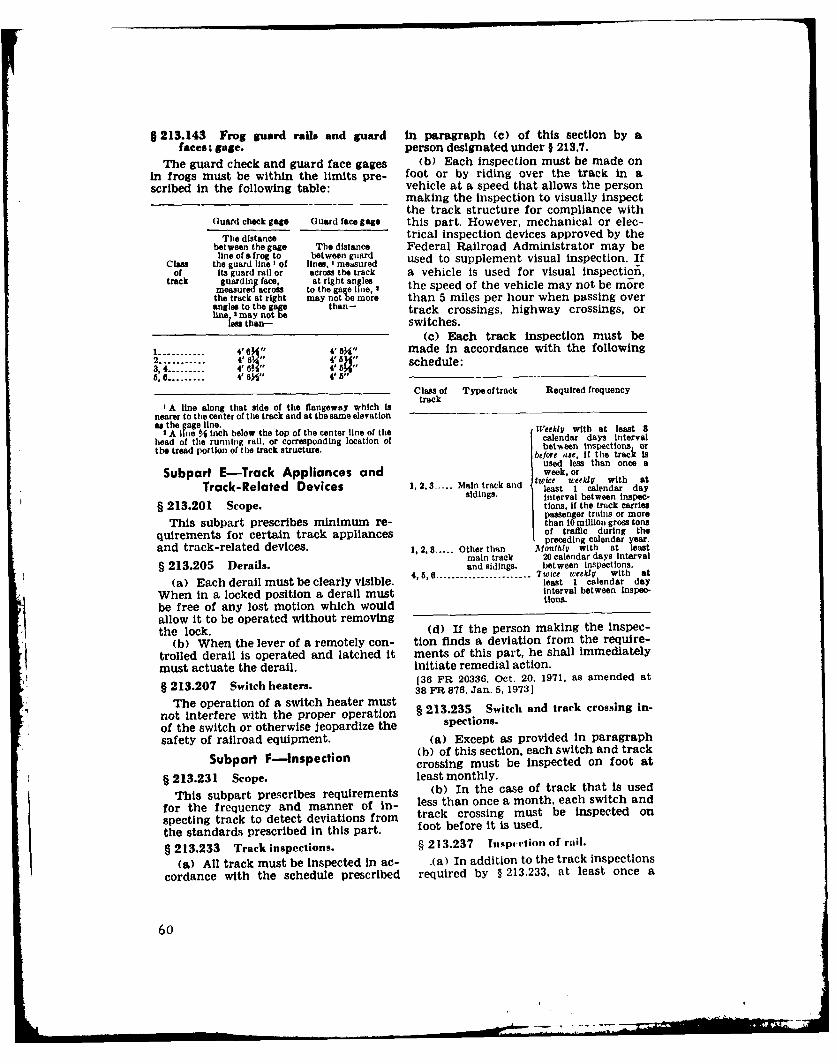
§ 213.143 Frog guard rails and guard in paragraph (c) of this section by a
faces; gage. person designated under § 213.7.
The guard check and guard face gages (b) Each inspection must be made onin frogs must be within the limits pre- foot or by riding over the track in ascribed in the following table: vehicle at a speed that allows the person
making the inspection to visually inspectthe track structure for compliance with
Guard check gage Guard face gage this part. However, mechanical or elec-The distance trical inspection devices approved by the
between the gage The distance Federal Railroad Administrator may becla lie oua frog to between guard used to supplement visual inspection. If
of Its guard rail or across the track a vehicle is used for visual inspection,track guarding face, at right angles
measured across to the gag line, the speed of the vehicle may not be mrethe track at right may notbe more than 5 miles per hour when passing overangles to the gage than- track crossings, highway crossings, orline I may not be
less than- switches.(c) Each track inspection must be
1 ------------- 4'" 4' 4" made in accordance with the following2 ------------ 4' BV" 4 " schedule:3,4 ----------- 4 6VA" :56, --------- 4' 64" 4 5"
Class of Type of track Required frequencytrack
I A line along that side of the flangeway which isnearer to the center of the track and at the same elevationas the gage line.
3A I ie % inch below the top of the center line of the eekly with at least head of the runnhig rail, or corresponding location of calendar days intervalthe tread portion of the track structure. be~ore use, If the track is
used less than once aSubpart E-Track Appliances and week, or
twice weekly with atTrack-Related Devices 1,2,3 ----- Main track and least 1 calendar daysidings. interval between inspec-
§ 213.201 Scope. tions, If the track carriespassenger trains or more
This subpart prescribes minimum re- than 10 million gross tonsquirements for certain track appliances of traffic during the
preceding calendar year.and track-related devices. 1,2.3 ..... Other than 2tfont~hy with at least
main track 20 calendar days Interval§ 213.205 Derails. and sidings. between inspections.
Each ~ ~ ~ 45, dealmseceal iil. ---------------- _--- Twice weekilt with at(a) Each derail must be clearly visible. least 1 calendar day
When in a locked position a derail must interval between Inspe-
be free of any lost motion which would tions.
allow it to be operated without removingthe lock. (d) If the person making the Inspec-
(b) When the lever of a remotely con- tion finds a deviation from the require-trolled derail is operated and latched it ments of this part, he shall immediatelymust actuate the derail. Initiate remedial action.§ 13.207 Switch heaters. 136 FR 20336, Oct. 20, 1971, as amended at
§ 38 FR 876, Jan. 5, 1973]
The operation of a switch heater mustnot interfere with the proper operation § 213.235 Switch and track crossing in-
of the switch or otherwise jeopardize the spections.
safety of railroad equipment. (a) Except as provided in paragraph
Subpart F-lnspection (b) of this section, each switch and trackcrossing must be inspected on foot at
§ 213.231 Scope. least monthly.
This subpart prescribes requirements (b) In the case of track that Is used
for the frequency and manner of in- less than once a month, each switch and
specting track to detect deviations from track crossing must be inspected on
the standards prescribed in this part. foot before it is used.
§ 213.233 Track inspections. § 213.237 InspcIrion of rail.
(a) All track must be inspected in ac- .(a) In addition to the track inspections
cordance with the schedule prescribed required by § 213.233, at least once a
60

year a continuous search for internal de- § 213.241 Inspecion records.fects must be made of all jointed and (a) Each owner of track to which thiswelded rails in Classes 4 through 6 track, part applies shall keep a record of eachand Class 3 track over which passenger inspection required to be performed ontrains operate. However, in the case of that track under this subpart.a new rail. if before installation or within (b) Each record of an inspection un-6 months thereafter it is inductively or der §§ 213.233 and 213.235 shall be pre-ultrasonically inspected over its entire pared on the day the inspection is madelength and all defects are remcved, the and signed by the person making the
next continuous search for internal de- inspection. Records must specify thetrack inspected, date of inspection, lo-
fects need not be made until 3 years cation and nature of any deviation fromafter that inspection, the requirements of this part, and the
(b) Inspection equipment must be remedial action taken by the personcapable of detecting defects between making the inspection, The owner shallJoint bars, in the area enclosed by Joint retain each record at its division head-bars. quarters for at least 1 year after the
(c) Each defective rail must be inspection covered by the record.marked with a highly visible marking on (c) Rail inspection records must spec-both sides of the web and base. ify the date of inspection, the location,[36 FR 20336, Oct. 20, 1971, as amended at and nature of any internal rail defects28FR876, Jan. 5, 1973J found, and the remedial action taken
and the date thereof. The owner shall
§ 213.239 Special inspeetions. retain a rail inspection record for atleast 2 years after the inspection and
In the event of fire, flood, severe storm, for 1 year after remedial action is taken.or other occurrence which might have (d) Each owner required to keep in-damaged track structure, a special in- spection records under this section shallspection must be made of the track in- make those records available for inspec-volved as soon as possible after the tion and copying by the Federal Railroadoccurrence. Administrator.
APPENDIX A-MAXIM1M ALLOWABLP OPERATING SPEEDS FOR CURVED TRACK
Elevation of outer rail (inches)
Degree of 0 Y 1 11 2 21 3 314 4 414 5 51) 6Curvature
Maximum allowable operating speed (mph)
0(P ---- 93 tOo 107 ....................................... .....................0O41Y....... .. 0 87 93 98 103 109 .................. .............0*50, ....... 72 78 83 88 93 97 101 106 110 _ _.........................lo0 _ ...0.. 66 71 76 80 85 89 93 96 100 104 107 110 ....1°15,....... . 9 63 6 72 76 79 83 86 89 93 96 99 1011°30 ...... 54 5% 2 66 69 72 76 79 82 86 87 90 931145 ........ 50 54 57 61 64 67 70 73 76 78 8i 83 862*0Y ....... 46 50 5A 57 W0 63 66 68 71 73 76 78 so
215 36.3.42. 44 47 50 54 56 59 62 64 67 69 71 74 6.k,203(Y.... 41 45 48 51 54 56 59 61 62, 6 %, 70 72
245'. 40 43 40 48 51 54 50 52 60 62 65 66 68
3409 4 38 41 44 46 49 1 54 50 52 60 55 64 93015' ....... 3 39 42 45 47 49 46 48 50 57 59 61 63430 ....... 35 33 40 43 45 47 50 52 54 55 57 59 61Y45 - - 34, 37 39 3 41 4 46 48 50 52 549 594°00 ....... 33 35 39 40 42 4A= 46 48 50 52 54 55 b7
430 ...... 2 30 36 38 36 48 40 45 47 44 40 42 4600 .... 7 29 32 3 334 3 33 40 41 443 2 48 49 515*30' .... . 28 2 30 31 33 3 36 38 3 44 42 47 48
00' 2. 27 29 31 3 3 35 36 3 39 41 42 44 45 466o030 - 23 2 30 31 33 35 36 38 39 41 40 43 457 0 ....... 25 27 29 30 32 34 35 36 38 39 40 42 438100' ....... 23 25 27 28 30 31 33 34 35 37 38 3 40}°00" ....... 22 24 256 27 28 30 31 32 33 35 36 31" 381l°(}0 ------ 21 22 24 25 27 28 29 31 32 33 34 35 36
1100' .. 20 21 23 24 26 27 2R 29 30 31 32 33 341200'. 19 20 22 23 24 26 27 28 29 30 31 32 3
136 FR 20336, Oct. 20, 1971, as amended at 38 FR 876, Jan. 5, 19731
61

APPENDIX B
PROPOSED RAIL OUTLOADING PROCEDURE FOR A MOBILIZATION MOVE AT CAMP RIPLEY
Maximum rail outloading operations use a cyclic schedule to mininmize con-
flicts and improve control. The recommended rail outloading plan, Plan 4,for Camp Ripley and the BNRR main line trackage serving Camp Ripley isincluded in figure 23. Plan 4 requires that approximately 206 railcars(106 from Camp Ripley and 100 from the BNRR main line track) be out-
loaded per day.
The simulation begins with the assumption that it takes several days to
accumulate the necessary number of railcars to start full-scale outloadingoperations. Locomotives position the arriving cars at the designated load-out sites according to a preconceived plan. Simultaneously, the equipmentto be loaded aboard the cars is prepared and staged. Personnel should be
used to throw switches and act as road guards at all rail/highway crossingsto reduce delays and insure a safer operation. The particular outloading
scheme for Camp Ripley follows. The times required for various railcarswitching operations are shown in table 10.
The cycle starts when loading begins at daylight, which is defined as zerohour. Loading and securing tiedowns or blocking and bracing will be com-pleted within 7 hours, during daylight hours. The railcar switching opera-tions will follow and must be finished in 17 hours so that the next cycle can
begin the next day. That is, the loaded cars must be removed, assembledinto trains, and sent toward their destination, and empty cars must beplaced at the loading sites before daylight the next morning.
The switching sequence begins at the conclusion of blocking and bracing and
inspection, which is 7 hours elapsed time after the cycle began. Four120-ton locomotives couple with 50 loaded cars at loading site L5, on theBNRR track main line at the entrance to Camp Ripley. The temporary end-
loading ramp placed there has been removed and the 50 loaded cars arepushed northward up the main line until they couple with the 50 loaded carsat site L4. Site L4 is a loading site consisting of a temporary end-loadingramp, placed on the main line, approximately 6, 400 feet north of the
switch, at the north leg of the Camp Ripley wye. The train of 100 loadedrailcars departs for Little Falls, picks up its caboose, and thence leavesfor the POE. As soon as this train clears the main line that leads fromLittle Falls to Camp Ripley, the second group of four 120-ton locomotivesproceeds to loading site L3, along Bettenberg Avenue, 1.,-,ere they couplewith seven boxcars. These cars are pushed westward until they couple
63
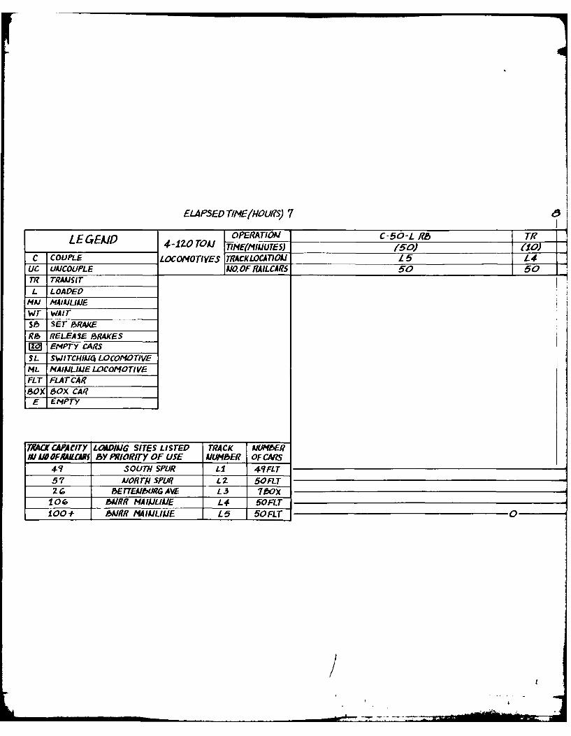
ELAPSED TIt4EM4OUS) 7 I
LE EAD PERATIOAI C-50-L-R8 TI? ILEG P4-120 TOMJ TIMEt'MIATES) (50) t10C COUPLE LOCOMOTIVES TRACKLOCATIOJ Is t 4
LIC UAICOLJPLE A10.OFRAILCARS 50 5077? TRAAJSITL LOADED
MAJ AJAJUAJEwr wAITSI! SET SRAJKER P RELEASE 83RAKESWo EMPTY CARSSL SWITCiIAR4 LOCOMOTIVEML NAIPJLIAJELWCOMOTIVEFLT FLATCAR?SOXK SOX CAI?
TX4C CAACITY LOAD/AIG SITES LimTE TRACK PJIMEERNWAM OFMAi &AU Y PRIORITY OF USE AUMER OF CARS
4?7 SOUTH SPUR LI 4?FLT57 AJORT/ISLII? L2L 5OFLT
______o 8E rEABLIRG AVE L3 7wX106 BA//JR MA ILI E 1-4 50FLT1001- PA/R MI4AlL/IAE L£5 50OFLT 0

TR -0- ?b7 ST TRAINJ OF LOADE19 CARS ARRIIVES(00) ______ LITT 111LE FALLS CLASSIFICATIOAJ YARD,
1-4 4 L1TI- FALS PIKS-P CA)05EAW EPARTS FOR14 LITLE ALLS PoE. 5 LocomoTIVEsDEPAI?T FolR CAM
50 ____lo_ RIPLEY To PICK-UP ZAND 77?AIAI.
OPE RATI OAl TI? IC-7-r Tir4-IzOTOAJ 71NE(mINITE) 1(21) (7) (3
LOCOMtOTIVES TIACK LOCATION CA NPIiIPLEYL3 IL3 ILZA1. OF RA ILCA RS 0 7 7
00

10 1
IVL 1 3 -120 TON TINEA7OAFOR LOCOMOTIVES M~
P 106 EMPTIESI ACOCA11
C-50-L N3 ~ TI? C-49-L Rib t(50) (15) (4? (3)
/L2 LI LI ITTLE FALLS57 57 loo loo
00
Figure Z
64
3tI'mob

OPERA TIOA r/I? UC-49?-E SAMNuTES) (25) (54)
ACKLOCATIOA LI LID aILCAMS 106 57
IJD TRAIN OF LOADED CARS ARRIVES AT LITTLE FLLSCLASSIFICATION YARD PICKS UP CAOOSEAAJ D DEPARTS FOR PE. 3 LOCOMOTIVES
FALL-5 DEPART FOR CAMP RIPLEY IITI 1 EMPTY06 RAILCAAS.
L4-i5-
Figure 23. Rail outloading simulation, Camp Ripley.
K./
' ... . ... _ .~ ~~. _4 , _. ll
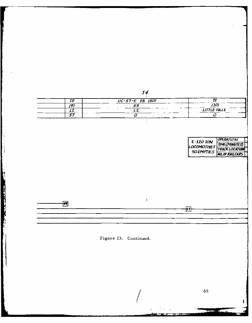
14
M UC-57-E S1 (50) TI?___(7) 55 (30) ___
L2 LZ LITTLE FALLS57 0 0
-10 TON OPERA TIVAJTINE(MIA1UTES)
LOOMOTIVES TOfCKLOCATI5oR IES IAO. FR IL 4CA9S
1
Figure 23. Continued.
65

2 -1WAI OPERA TIALOCOMOTIVES TIME(IMIAIUT(S)
50 MPTES RACVLOCATION_
OAJ R UC-50-E S8, TI?
LATN L4 L 4 LTiTLE FALLS95R 50 0 10

C 7- r/l LJ71S13- TI? UC-50 -F S6
a I Z L.4 L3 L5 L.6us 5 7 57 50 50

Ic, 20
-E S~T115l) (30)5 LITTLE FALLS
a C
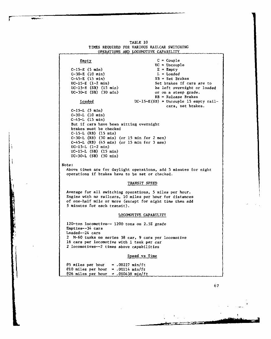
TABLE 10TIMES REQUIRED FOR VARIOUS RAILCAR SWITCHING
OPERATIONS AND LOCOMOTIVE CAPABILITY
Empty C = CoupleUC - Uncouple
C-15-E (5 min) E = EmptyC-30-E (10 min) L = LoadedC-45-E (15 min) SB = Set BrakesUC-15-E (1-2 min) Set brakes if cars are toUC-15-E (SB) (15 min) be left overnight or loadedUC-30-E (SB) (30 min) or on a steep grade.
RB = Release BrakesLoaded UC-15-E(SB) = Uncouple 15 empty rail-
cars, set brakes.C-15-L (5 min)C-30-L (10 min)C-45-L (15 min)But if cars have been sitting overnightbrakes must be checkedC-15-L (RB) (15 min)C-30-L (RB) (30 min) (or 15 min for 2 men)C-45-L (RB) (45 min) (or 15 min for 3 men)UC-15-L (1-2 min)UC-15-L (SB) (15 min)UC-30-L (SB) (30 min)
Note:Above times are for daylight operations, add 5 minutes for nightoperations if brakes have to be set or checked.
TRANSIT SPEED
Average for all switching operations, 5 miles per hour.Engine with no railcars, 10 miles per hour for distancesof one-half mile or more (except for night time then add5 minutes for each transit).
LOCOMOTIVE CAPABILITY
120-ton locomotive-- 1200 tons on 2.5% gradeEmpties--34 carsLoaded--24 cars2 M-60 tanks on series 38 car, 9 cars per locomotive16 cars per locomotive with 1 tank per car2 locomotives--2 times above capabilities
Speed vs Time
@5 miles per hour = .00227 mmn/ft@10 miles per hour - .00114 min/ft@26 miles per hour = .000438 mninft
67
,4
.r

with the 50 loaded cars at site L2. The train of 57 cars reverses direction,backing the cars eastward until the last car clears the switch to loadingsite Ll. The train stops, reverses, and then pushes the 57 cars onto trackLl until they couple with the 49 cars already there, making a train of 106loaded cars. This train proceeds to Little Falls, picks up its caboose, anddeparts for the POE. A total of 206 loaded cars have been removed fromCamp Ripley and are en route to the POE (total elapsed time--l2 hours).
Now the loading sites must be filled with empty cars for the next day'swork. As soon as the second train of loaded cars clears the track toCamp Ripley, the first train of 106 empties departs from Little Falls.(For the boxcars to be positioned at Camp Ripley at the correct loadingsite they should be adjacent to the locomotives in the train leaving LittleFalls.) The train proceeds north up the main line until the last car clearsthe switch of the north leg of the wye leading into Camp Ripley. The trainthen backs through the north leg of the wye and onto loading site LI, where49 cars are positioned with their brakes set for loading. The train re-verses direction until the switch at LI/L2 is cleared, then pushes the re-maining 57 cars onto L2. The brakes are set on the 50 flatcars; the box-cars are left temporarily so that sufficient track will be available alongBettenberg Avenue for placing the empties at loading sites L4 and L5. Thelocomotives return to Little Falls. As soon as they clear the track toLittle Falls the second train, consisting of 50 empty flatcars, departs forCamp Ripley. The train heads north to the south leg of the wye, proceedswestward onto L3 loading site, reverses direction and pushes the carsthrough the north leg of the wye northward and into position at loading siteL4. The brakes are set and the locomotives proceed south to Little Falls.As soon as they clear the track to Camp Ripley, this cycle's third and lasttrain of 50 empties, proceeds north to L2 at Camp Ripley. The locomotivein front couples with the seven boxcars left there by the first train ofempties9, reverse direction, pushing the 50 flatcars toward the north leg ofthe wye. The train stops at the L3 boxcar loading site, the seven boxcarsare positioned, then the train pushes the 50 flatcars through the north legof the wye. When the locomotives clear the switch at the main line, theyproceed south pulling the 50 flatcars into position at loading site L5. This
- A completes the cycle and the locomotives return to Little Falls. Totalelapsed time for the entire cycle is 19 hours and 44 minutes.
68
APPENDIX C
SPECIAL-PURPOSE RAILCARS AND LOADING/UNLOADING PROCEDURES
Specially designed railcars, in particular those used for transporting
vehicles, can greatly increase the speed and efficiency of a rail outloading
operation. Bilevel and integral chain tiedown flatcars are the primary
means of enhancing the loadout routine of most military vehicles. Bilevel
railcars are best suited for the smaller vehicles, including 2-1/2-ton
trucks. Although trilevel cars are in abundant supply, their relatively
low deck clearances prohibit the movement of most military equipment and
therefore, cannot be considered a significant resource.
The integral tiedown flatcars will accommodate larger vehicles, including
tanks. Loading and securing equipment on these railcars can be acceler-
ated to 15 minutes per vehicle, for small vehicles, versus approximately
45 minutes for blocking and bracing procedures used on standard-type
railcars. Also, the BTTX 89-foot flatcar has a capacity of six 2-1/2-ton
trucks, doubling the single level capacity. Thus, in speed and capacity,
special-purpose railcars are an advantage worth investigating.
There are essentially five methods of loading/unloading multilevel rail-
cars; they are:
1. The "K" loader of 463L aircraft cargo-loading system.
2. The forklift and pallet used in conjunction with a crane and/or
ramp.
3. The crane and ramp combination.
4. Adjustable ramps.
5. Adjustable built-in ramp on multilevel railcars.
The procedures used with each of the above are described in detail in
TM 55-625', as are tiedown procedures.
As of 1970, more than '0 percent of DOD installations had no organic
capability to load/unload multilevel railcars. No outloading plans should
include the use of these railcars until a thorough investigation verifies
6/- TM 55-625, Transportability Criteria and Guidance, Loading and Un-
loading Multilevel Railcars at Military Installations in the United States.
69

their availability at the time required. The supply of special-purpose
flatcars with integral tiedowns is also limited. As a result, even though
these types of railcars are very valuable for volume rail outloading opera-
tions, their availability is seriously in question unless advance preparations
are made.
The following trends in flatcar supply are now operative and have beensince the development of modern piggyback service in the mid-1950's:
1. The size of the flatcar fleet has been growing, both in number of
flatcars and in relation to the size of the car fleet as a whole.This gain has been confined to specialized cars; for example,
trailer-on-flatcar, container-on-flatcar, bilevel, trilevel, and
bulkhead flatcars.
2. The size of the general-purpose flatcar fleet has decreased,
though average length and capacity have increased.
3. A majority of all flatcars are owned by car companies, not by the
railroads. Therefore, more flexibility in assignment, withimproved utilization, has resulted. Fewer idle cars areavailable for short-notice use than would be if each rail-
road maintained an adequate supply for its own needs.
Considering these trends, the sizes of the various components of the
specialized flatcar fleet, and the blocking and bracing requirements for
the various types of equipment to be shipped by rail, it does not appearprudent to express an installation's needs and outloading plan using only
general-purpose flats. The TOFC fleet, in particular, is now most likely
large enough to fill military requirements (table 11). The COFC fleet also
has expanded to the point that it could carry most of the military's con-
tainer movements, especially since COFC cars are used almost exclusive-
ly for import/export movements, which likely would be greatly disruptedin a mobilization period.
Accordingly, vans or containers should be outloaded on TOFC cars. If
the movement is to a port for ocean shipment by other than RORO vessel,
the use of COFC cars should be considered. However, the availability ofCOFC cars in the quantity desired without disrupting civilian container
movements is highly improbable.
Other cars in the specialized flatcar fleet generally are assigned to spe-
cific services or to a carpool for one shipper's exclusive use. Therefore,
although these cars can save blocking and bracing and should be requestedwhen they can be employed profitably in a specific move, the likelihood of
obtaining the cars is too weak to base outloading requirement on their use.
70

TABLE I ITRAILER TRAIN COMPANY FLEET
Trailer Train Company ownership of selected car types as contained in the January 1979 Official
Equipment Register. Trailer Train owns in excess of 95 percent of total US ownership of TOFC, C
autorack cars.
Type Reporting Marks Quantity
Flatcars ATTX 303
with special FTTX 1,839
equipment. HTTX 763
See Legend ITTX 1,164
JTTX 2,474MTTX 1,239
OTTX 2,519
PTTX 926
TTDX 222
TTHX 391
TTJX 205TTMX 21
TTPX 1,426
ZTTX 72
13,564
TOFC TTX 28,908
TTAX 6,874 (see also COFC)
GTTX 2,251
LTTX 2,027
XTTX 702
40,762
COFC TTAX 6,874 (see also TOFC)
TTCX 699
7,573
Bilevels BTTX 1,882
2 TTBX 5,720TTGX 1,002
TTSX 8
8,612
Trilevels CTTX 1,002
ETTX 5,034KTTX 1,160
RTTX 2,540
TTKX 6,703TTRX 2,696
19,135
Legend - Definitions of Trailer Train Company's reporting marks
ATTX - Flatcars, equipped with two continuous tiedown loops on center sills, continuous tiedown
each side, and bridgeplates. Not equipped with hitches, chains, jacks, and so forth.
BTTX - Flatcars equipped with bilevel autoracks, furnished by participant railroads.
CTTX - Flatcars equipped with coverless inclosed trilevel autoracks, furnished by participant ra
ETTX - Flatcars equipped with fully inclosed trilevel autoracks, furnished by participant railrc
FTTX - Flatcars equipped with tiedown devices for loading automobile or truck frames.
GTTX - Flatcars equipped with hitches and bridgeplates for transporting trailers. Cars built b]
American Transportation Corporation.
HTTX - Flatcars equipped with 38 heavy-duty chains, with snubbers and turnbuckles, each secured'
and retractable tiedown winches in 4 longitudinal channels for transporting I1rge, earthl
equipment.
ITTX - Flatcars equipped with end pedestals, and 62 tiedown winches with chains and bridgeplat
'9 official Railwayof -ToFCCOFC, and
tlso COFC)
tlso TOMC

and retractable tiedown winches in 4 longitudinal channels for transporting lre, earthequipment.
ITTX - Flatcars equipped with end pedestals, and 62 tiedown winches with chains and bridgeplates,transporting trailer tractors saddleback style.
JTX - Flatcars specially modified or equipped by participant railroads with miscellaneous devicesspecial services.
KTTX - Flatcars equipped with hinged-end trilevel autoracks, furnished by participant railroads.LTTX - Low-deck flatcars equipped with hitches and bridgeplates.MTTX - Sixty-ft flatcars with stake pockets and lading strap anchors for general service, or 85-ft
flatcars with 16 stake pockets, 8 per side, for transporting long pipe.OTTX - Flatcars equipped with 64 chains, with snubbers, each secured to movable and retractable tie
winches in 4 longitudinal channels, for transporting agricultural equipment.PTTX - Flatcars equipped with bulkheads, spaced 48 ft 6 in. apart, for transporting plywood, wallbo
and so forth.RTTX - Flatcars equipped with fixed trilevel autoracks, furnished by participant railroads.TTAX - Flush deck flatcars equipped with movable foldaway container pedestals, knockdown hitches,
bridgeplates, for transporting trailers or containers or combinations of both.TTBX - Flatcars equipped with bilevel autoracks, furnished by participant railroads.TTCX - Flush deck flatcars equipped with movable foldaway container pedestals for transporting contTTDX - Flatcars equipped with 16 tiedown winches with chains and bridgeplates, for transporting
military vehicles semi-saddleback style.TTGX - Flatcars equipped with fully inclosed bilevel autoracks, furnished by participant railroads.TTHX - Flatcars equipped with heavy-duty chains anchored to removable stake pocket castings. When
downs are removed, car becomes same as 60-ft cars stencilled "MTTX.'TTJX - Sixty-eight-ft, 90-ton flatcars with special tiedown devices, fixtures, and stake pockets.TTKX - Flatcars equipped with hinged-end trilevel autoracks, furnished by participant railroads.TTMX - Sixty-eight-ft, 100-ton flatcars with stake pockets and lading strap anchors 'or general serTTPX - Flatcars equipped with bulkheads spaced 62 ft 0 in. apart and 17 transverse tiidown anchors
chains, used for transporting wallboard, plywood, and so forth.TTRX - Flatcars equipped with fixed trilevel autoracks, furnished by participant railroads.TTSX - Flatcars equipped with coverless inclosed bilevel autoracks, furnished by participant railroTTVX - Flatcars equipped with Vert-A-Pak superstructure, furnished by participant railroads.TTX - Flatcars equipped with hitches and bridgeplates for transporting trailers. See Note 1.XTTX - Flatcars equipped with four hitches and bridgeplates for transporting two trailers, one
45-ft and one 40-ft, or three 28-ft trailers.ZTTX - Flatcars equipped with 30 stake pockets, 15 per side, for transporting long poles.Note I - TTX 105-109 are specially equipped, multihitch instruction cars, not suitable for revenue
service. For disposition or further informatioi on these cars, contact Mr. M. B. Flagg,Inspection and Training, Trailer Train Company, 300 So. Wacker Dr., Chicago, IL 60606.
o movable
ving
,for
es f or
ffttiedowniboard,
a, and
containers.
ads.en tie-
S.V
service.ors with
airoads.
enue
gg, Manager,
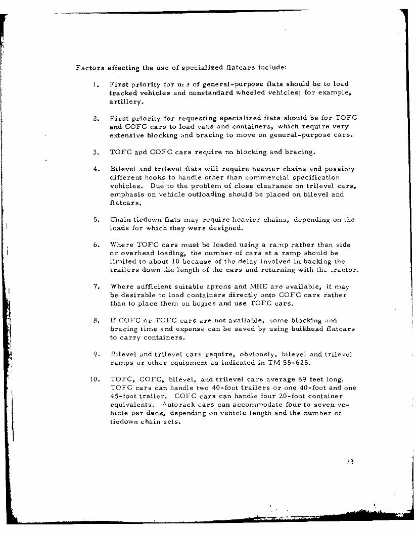
Factors affecting the use of specialized flatcars include:
1. First priority for u, - of general-purpose flats should be to loadtracked vehicles and nonstandard wheeled vehicles; for example,artillery.
2. First priority for requesting specialized flats should be for TOFCand COFC cars to load vans and containers, which require veryextensive blocking and bracing to move on general-purpose cars.
3. TOFC and COFC cars require no blocking and bracing.
4. Bilevel and trilevel flats will require heavier chains and possiblydifferent hooks to handle other than commercial specificationvehicles. Due to the problem of close clearance on trilevel cars,emphasis on vehicle outloading should be placed on bilevel andflatcars.
5. Chain tiedown flats may require heavier chains, depending on theloads for which they were designed.
6. Where TOFC cars must be loaded using a ramp rather than sideor overhead loading, the number of cars at a ramp should belimited to about 10 because of the delay involved in backing thetrailers down the length of the cars and returning with th,. ractor.
7. Where sufficient suitable aprons and MHE are available, it maybe desirable to load containers directly onto COFC cars ratherthan to place them on bogies and use TOFC cars.
8. If COFC or TOFC cars are not available, some blocking andbracing time and expense can be saved by using bulkhead flatcarsto carry containers.
9. Bilevel and trilevel cars require, obviously, bilevel and trilevelramps or other equipment as indicated in TM 55-625.
10. TOFC, COFC, bilevel, and trilevel cars average 89 feet long.TOFC cars can handle two 40-foot trailers or one 40-foot and one45-foot trailer. COFC cars can handle four 20-foot containerequivalents. Autorack cars can accommodate four to seven ve-hicle per deck, depending on vehicle length and the number of
tiedown chain sets.
73
11. Tracks used to store or load cars 89 feet long should be reachable
without going through curves exceeding 14-degree curvature, and
tracks used for cars between 55 and 65 feet should be reachable
without going through curves exceeding 15-degree curvature.
74

APPENDIX D
DEPARTMENT OF TRANSPORTATION - FEDERAL RAILROAD ADMINISTRATION,CAMP RIPLEY TRACK INSPECTION REPORT
DEPARTMENT OF TRANSPORTATIONFEDERAL RAILROAD ADMINISTRATION
456 Federal Bldg. P U. S. Courthouse110 South 4tLh Street
Minneapolis, Minnesota 55401
June 18, 1979
Mr. John Grier, MTMC-TEA12388 Warick Blvd.P. 0. Box 6276Newport News, Virginia 23606
Dear Mr. Grier:
Please find below a description of deviations noted inour walking inspection of trackage within the confinesof Camp Riply conducted on June 4, 1979, on which wewere accompanied by Camp Engineer, Col. Wilcjek. Thedefects are listed according to the sequence ofinspection.
North track within the compound west of unloadingtrack switch the following defects were noted.
1 location of tight gage measured 55-3/4 inches1 loose joint10 locations of missing bolts
Rail in this track is 72 lb. secured by 11/16 inch boltsin 4 hole bars, single shoulder tie plates and 2 railholding spikes.
South track within the compound west of unloading track:4 switch the following defects were noted.
3 locations of tight gage measured 55-3/4inches due to slued ties4 cracked or broken joint bars *4 locations of missing bolts1 broken rail horizontal split web2 locations of worn joint bars1 location of wide gage
The rail is 66.02 lb. secured with 4 hole joint bars,single shoulder tie plates and 2 rail holding spikes.
75

-2
The single track between unloading track switch and westwye switch had the following defects.
3 locations of bolts missing1 location of defective ties measured 76 inches2 locations of tight gage1 location of open switch point 1/4 inch
Rail is 72 lb. secured by 11/16 inch bolts, 4 hole jointbars, single shoulder tie plates, 2 rail holding spikes.
The track between west wye switch and south wye switc' onthe Burlington Northern is referred to as south leg ofthe wye.
3 locations of tight gage - 2 measured 55-3/4 inches,1 measured 55-1/2 inches2 locations of loose joints2 locations of bolts missing1 location of worn joint bars
Ral is 72 lb. secured by 11/16 inch bolts, 4 hole jointbars, single dioulder tie plates, 2 rail holding spikes.
The track between west wye switch and north wye switch onthe Burlington Northern is referred to as north leg ofthe wye.
2 locations broken joint bar3 locations bolts missing
Rail is 72 lb. secured by 11/16 inch bolts, 4 hole jointbars, single shoulder tie plates, 2 rail holding spikes.Surface, in general, is good over entire trackage.Although ties appear sound many are deteriorated on theunderside as tapping ties disclosed hollow soundindicative of internal deterioration. Trackage afterreported maintenance completion will meet or exceedClass #2 standards.
Sincerely yours
W. GinkelTrack Inspector, FRA
cc: J. J. Sharpe
76
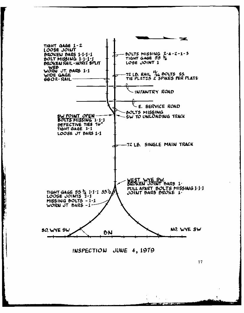
TIGH14T GAGE 1-ZLOOSE JOINTMO14EU AIl$ 1-1-1-1 ,--OLTS MISSIG Z-4-Z-1-3bOLT MISSING 1-1-1-i roc,141 ciAos 5OIOUEN %AIL-UWORIM SPLIr LOSE JOINT I
WTIWORNU JT. bAIs 1-1WIDE GAGE 7Z Lb. RAIL Y4WLT5 65G02- 9AIL TIE PL4TfS Z SPIKES IER PLATE
___INFANTR RO JAD
_________ - SERVICE ROAD
bOLTS MIs INoS W POINT OPEN- -$W TO UNLOADING TRACU, OLTS MOSSOl I 1-1-i
DEFECTIVE TIES (P"TI6T GAGE 1-1LOOSE JT 15ARS 1-1
t -7Z L., SINGLE MAIN T(ACK
i~iWEST )8!YE SW-
I bROKNP- JOINT 15ARS I-PULL APART 5OLTS MISSING 1-1-J
T,40T GATGE 55 4 1-1-1 55 JOINT IbAIZ5 I&004.E I-LOOSE JOINTS 1-1MISSING bOLTS - 1-1WORM JT IARS -1
so. %^F- SW Ajo. WVE sw
INSPECTIOUJ JUNE 4, 197o
77
DISTRIBUTION
Camp CommanderCamp RipleyLittle Falls, MN 56345 (2)
Camp CommanderATTN: ATSCamp RipleyLittle Falls, MN 56345 (25)
Chief, Army National Guard BureauRoom 2D424 PentagonATTN: NGB-ARL-TWASH, DC 20315 (4)
CommanderUS Army Forces CommandATTN: AFLG-TRU (2); AFEN-FEB (1); AFEN-ME (1)Fort McPherson, GA 30330 (4)
CommanderUS Army Readiness CommandATTN: J4MacDill Air Force BaseTampa, FL 33608 (4)
HQDA (DALO-TSM-P)Room ID616 PentagonWASH, DC 20310 (1)
USA TSARCOMSystems Analysis OfficeATTN: DRSTS-FR4300 Goodfellow BoulevardSt. Louis, MO 63120 (1)
Army Materiel Systems Analysis ActivityATTN: DRXSY-CLAberdeen Proving Ground, MD 21005 (1)
CommanderMilitary Traffic Management CommandATTN: MT-SA (2); MT-PLM (1)WASH, DC 20315 (3)
78
CommanderMilitary Traffic Management Command, Eastern AreaATTN: MTE-PLBayonne, NJ 07002 (6)
CommanderMilitary Traffic Management Command, Western AreaOakland Army BaseOakland, CA 94626 (2)
CommandantUS Army Transportation SchoolATTN: Transportation LibraryFort Eustis, VA 23604 (1)
DirectorMilitary Traffic Management CommandTransportation Engineering AgencyNewport News, VA 23606 (10)
8757-79
79