manager 3000 - mitsubishi electric
TRANSCRIPT

MANAGER 3000
INTERFACE MANUAL C0224122-11-15-EN
For software versions HG06
Replaces C0224122-05-12-EN
The information contained in this document may be modified without prior notice. No part of this document may be reproduced and/or disclosed to third parties or competitors.
November 2015
EN

C0224122-11-15-EN
2
Contents
1. USABILITY .................................................................................................................................................................................... 3
2. INTERFACING WITH THE BMS (MODBUS)................................................................................................................................. 4
2.1 Components required .............................................................................................................. 4 2.2 Installing the serial interface card ............................................................................................ 4 2.3 Setting supervisor parameters.................................................................................................. 5 2.4 Setting up the supervisor network ............................................................................................ 5 2.5 Interface database (software releases HG06 and higher) ........................................................... 6
3. INTERFACING WITH THE LONWORKS SYSTEM (ECHELON) ................................................................................................. 10
3.1 Components required ............................................................................................................ 10 3.2 Installing the serial interface card to the LONWORKS system ................................................... 10 3.3 Setting supervisor parameters................................................................................................ 11 3.4 Setting up the supervisor network .......................................................................................... 11 3.5 LONWORKS interface database (software releases HG04 and higher) ....................................... 11 3.6 Meaning of variables ............................................................................................................. 12
4. INTERFACING WITH THE BACNET SYSTEM ........................................................................................................................... 13
4.1 Components required ............................................................................................................ 13 4.2 Installing the serial interface card to the BACNET system ........................................................ 13 4.3 Setting supervisor parameters................................................................................................ 14 4.4 Setting up the supervisor network .......................................................................................... 14 4.5 Meaning of variables ............................................................................................................. 14
5. ANNEXES ................................................................................................................................................................................... 15
5.1 AWG (American Wire Gauge) conversion table ........................................................................ 15

C0224122-11-15-EN
3
1. Usability
This document exclusively refers to systems managed by the Manager 3000 electronic controller running on HG06 software. This version uses software release EA12r00 or higher in the I/O module. Information on the version of the software installed in the I/O module is shown in the “Configuration Test” screen which can be accessed as shown below.
Press [MENU] on the main screen of the display to access the user password-protected main menu.
Enter the user password. Confirm with “OK”.
Press this button to access manufacturer password-protected manufacturer menu.
Press “UP” and “DOWN” to scroll the list of available functions and press “Configuration Test”.
The “Configuration Test” screen displays any system configuration errors and information on the version and release
of the software installed on the I/O module (EA application).
In the example, I97 indicates that the code identifying the installed software is equal to 501, where 5 indicates the fifth letter of the alphabet “E” and 01 the first letter of the alphabet “A”, while I98 indicates software version 04, release 00 of the software installed. Press "Back" to return to the submenu.
The manufacturer menu is also used to access the other screens required to interface the Manager 3000 with the BMS. The electronic controller may only be installed and programmed by adequately trained technical staff.

C0224122-11-15-EN
4
2. Interfacing with the BMS (MODBUS)
2.1 Components required
Serial interface card PCOS004850.
Gateway inside the Manager 3000 panel, if requested by the customer.
2.2 Installing the serial interface card
The operations required to install and connect the components for interfacing the Manager3000 electronic controller with the BMS are shown below. The card must not be powered during these operations.
Remove the “Serial Card” cover of the gateway
Fit the BMS serial interface card (if not present) into the slot.
Put back the cover.

C0224122-11-15-EN
5
2.3 Setting supervisor parameters
To communicate with BMS, set the dedicated parameters via display (Manufacturer Menu - System Configuration) as shown below.
Par Description Value
P053 Superv. protocol 2 Protocol: Modbus / Standard
P054 Superv. speed 3
Communication speed: from 1200 baud to 19200 baud (0:1200 - 1:2400 - 2:4800 -
3:9600 - 4:19200)
P055 Superv. address 11 GATEWAY ID: from 001 to 200
IMPORTANT: to allow the parameter changes to be saved to the system, after making the changes perform the “Send
I/O module parameters” procedure (Manufacturer Menu – Send I/O module parameters), first making sure the system is OFF. Other non-modifiable supervisor connection settings:
Protocol Configuration
ModBus Data bits: 8
Parity: none
Stop bits: 2
Start Address: 1
2.4 Setting up the supervisor network
The supervisor network must be set up as shown below:
Tx/Rx -Tx/Rx +GND
Gateway
R=120
Scheda interfacciamento seriale
BMS
SCHERMO
Diagram showing a possible BMS supervision network layout
Take great care when installing the serial line. This is an RS485 serial line, based on a balanced differential communication line with a characteristic impedance of 120 ohm. The maximum length of the connection depends on the Baud-rate, background electrical noise, and the type and quality of the cable. Operation is generally guaranteed up to 1000 m. Use a twisted and shielded AWG 20/22 cable for the RS 485 serial line. The serial connection is made with a single cable running from the BMS to the gateway. The serial cable must be kept separate from the power cables. The shield of the connection cable must be earthed in just one point.
SCREEN
Serial interface board

C0224122-11-15-EN
6
2.5 Interface database (software releases HG06 and higher)
Register/Coil Modbus protocol
Protocol address: - Standard - Bacnet
Type Flow Description
40001 000 A NOT MANAGED
40002 001 A OUT Unit 1 evaporator inlet temperature
40003 002 A OUT Unit 1 evaporator outlet temperature
40004 003 A OUT Unit 1 recovery inlet temperature
40005 004 A OUT Unit 1 recovery outlet temperature
40006 005 A OUT Unit 2 evaporator inlet temperature
40007 006 A OUT Unit 2 evaporator outlet temperature
40008 007 A OUT Unit 2 recovery inlet temperature
40009 008 A OUT Unit 2 recovery outlet temperature
40010 009 A OUT Unit 3 evaporator inlet temperature
40011 010 A OUT Unit 3 evaporator outlet temperature
40012 011 A OUT Unit 3 recovery inlet temperature
40013 012 A OUT Unit 3 recovery outlet temperature
40014 013 A OUT Unit 4 evaporator inlet temperature
40015 014 A OUT Unit 4 evaporator outlet temperature
40016 015 A OUT Unit 4 recovery inlet temperature
40017 016 A OUT Unit 4 recovery outlet temperature
40018 017 A OUT Unit 5 evaporator inlet temperature
40019 018 A OUT Unit 5 evaporator outlet temperature
40020 019 A OUT Unit 5 recovery inlet temperature
40021 020 A OUT Unit 5 recovery outlet temperature
40022 021 A OUT Unit 6 evaporator inlet temperature
40023 022 A OUT Unit 6 evaporator outlet temperature
40024 023 A OUT Unit 6 recovery inlet temperature
40025 024 A OUT Unit 6 recovery outlet temperature
40026 025 A OUT Unit 7 evaporator inlet temperature
40027 026 A OUT Unit 7 evaporator outlet temperature
40028 027 A OUT Unit 7 recovery inlet temperature
40029 028 A OUT Unit 7 recovery outlet temperature
40030 029 A OUT Unit 8 evaporator inlet temperature
40031 030 A OUT Unit 8 evaporator outlet temperature
40032 031 A OUT Unit 8 recovery inlet temperature
40033 032 A OUT Unit 8 recovery outlet temperature
40034 033 A OUT Unit 1 condenser inlet temperature
40035 034 A OUT Unit 1 condenser outlet temperature
40036 035 A OUT Unit 2 condenser inlet temperature
40037 036 A OUT Unit 2 condenser outlet temperature
40038 037 A OUT Unit 3 condenser inlet temperature
40039 038 A OUT Unit 3 condenser outlet temperature
40040 039 A OUT Unit 4 condenser inlet temperature
40041 040 A OUT Unit 4 condenser outlet temperature
40042 041 A OUT Unit 5 condenser inlet temperature
40043 042 A OUT Unit 5 condenser outlet temperature
40044 043 A OUT Unit 6 condenser inlet temperature
40045 044 A OUT Unit 6 condenser outlet temperature
40046 045 A OUT Unit 7 condenser inlet temperature
40047 046 A OUT Unit 7 condenser outlet temperature
40048 047 A OUT Unit 8 condenser inlet temperature
40049 048 A OUT Unit 8 condenser outlet temperature
40091 090 A OUT Cold/hot circuit inlet temperature
40092 091 A OUT Cold/hot circuit outlet temperature
40093 092 A OUT Recovery circuit inlet temperature
40094 093 A OUT Recovery outlet circuit temperature
40095 094 A IN / OUT Cold temperature setpoint

C0224122-11-15-EN
7
Register/Coil Modbus protocol
Protocol address: - Standard - Bacnet
Type Flow Description
40096 095 A IN / OUT Cold temperature adjustment band
40097 096 A IN / OUT Hot temperature setpoint
40098 097 A IN / OUT Hot temperature adjustment band
40099 098 A IN / OUT Recovery temperature setpoint
40100 099 A IN / OUT Recovery temperature adjustment band
40101 100 A OUT Cold/hot active temperature setpoint
40102 101 A OUT Recovery temperature active setpoint
40103 102 A OUT External air temperature
001 000 B NOT MANAGED
002 001 B OUT Unit 1 offline (0: unit online – 1: unit offline)
003 002 B OUT Unit 2 offline (0: unit online – 1: unit offline)
004 003 B OUT Unit 3 offline (0: unit online – 1: unit offline)
005 004 B OUT Unit 4 offline (0: unit online – 1: unit offline)
006 005 B OUT Unit 5 offline (0: unit online – 1: unit offline)
007 006 B OUT Unit 6 offline (0: unit online – 1: unit offline)
008 007 B OUT Unit 7 offline (0: unit online – 1: unit offline)
009 008 B OUT Unit 8 offline (0: unit online – 1: unit offline)
091 090 B IN / OUT System on/off command (0: system off – 1: system on)
095 094 B IN / OUT Unit 1 enable (0: unit disabled – 1: unit enabled)
096 095 B IN / OUT Unit 2 enable (0: unit disabled – 1: unit enabled)
097 096 B IN / OUT Unit 3 enable (0: unit disabled – 1: unit enabled)
098 097 B IN / OUT Unit 4 enable (0: unit disabled – 1: unit enabled)
099 098 B IN / OUT Unit 5 enable (0: unit disabled – 1: unit enabled)
100 099 B IN / OUT Unit 6 enable (0: unit disabled – 1: unit enabled)
101 100 B IN / OUT Unit 7 enable (0: unit disabled – 1: unit enabled)
102 101 B IN / OUT Unit 8 enable (0: unit disabled – 1: unit enabled)
103 102 B IN / OUT Demand Limit command from supervision (0: command inactive – 1: command active)
40129 000 I NOT MANAGED
40130 001 I OUT Unit 1 cold/hot demand percentage
40131 002 I OUT Unit 1 cold/hot active percentage
40132 003 I OUT Unit 1 recovery demand percentage
40133 004 I OUT Unit 1 recovery active percentage
40134 005 I OUT Unit 2 cold/hot demand percentage
40135 006 I OUT Unit 2 cold/hot active percentage
40136 007 I OUT Unit 2 recovery demand percentage
40137 008 I OUT Unit 2 recovery active percentage
40138 009 I OUT Unit 3 cold/hot demand percentage
40139 010 I OUT Unit 3 cold/hot active percentage
40140 011 I OUT Unit 3 recovery demand percentage
40141 012 I OUT Unit 3 recovery active percentage
40142 013 I OUT Unit 4 cold/hot demand percentage
40143 014 I OUT Unit 4 cold/hot active percentage
40144 015 I OUT Unit 4 recovery demand percentage
40145 016 I OUT Unit 4 recovery active percentage
40146 017 I OUT Unit 5 cold/hot demand percentage
40147 018 I OUT Unit 5 cold/hot active percentage
40148 019 I OUT Unit 5 recovery demand percentage
40149 020 I OUT Unit 5 recovery active percentage
40150 021 I OUT Unit 6 cold/hot demand percentage
40151 022 I OUT Unit 6 cold/hot active percentage
40152 023 I OUT Unit 6 recovery demand percentage
40153 024 I OUT Unit 6 recovery active percentage
40154 025 I OUT Unit 7 cold/hot demand percentage
40155 026 I OUT Unit 7 cold/hot active percentage
40156 027 I OUT Unit 7 recovery demand percentage
C0224122-11-15-EN
8
Register/Coil Modbus protocol
Protocol address: - Standard - Bacnet
Type Flow Description
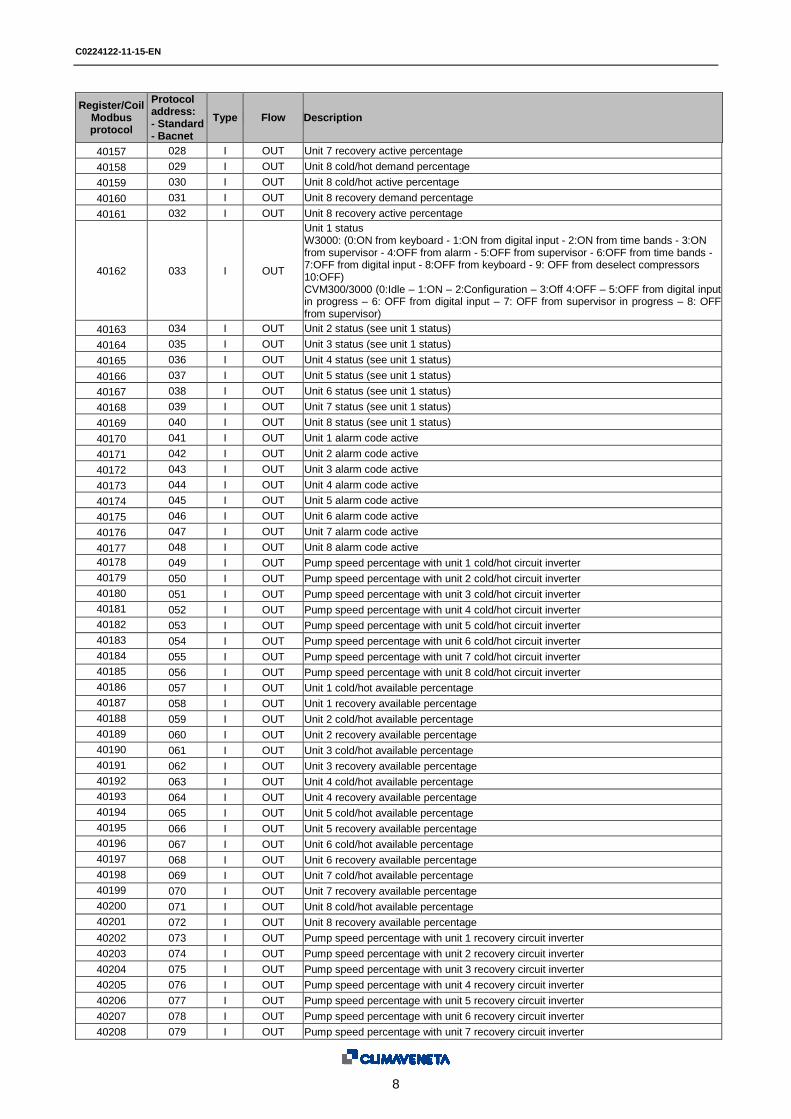
40157 028 I OUT Unit 7 recovery active percentage
40158 029 I OUT Unit 8 cold/hot demand percentage
40159 030 I OUT Unit 8 cold/hot active percentage
40160 031 I OUT Unit 8 recovery demand percentage
40161 032 I OUT Unit 8 recovery active percentage
40162 033 I OUT
Unit 1 status W3000: (0:ON from keyboard - 1:ON from digital input - 2:ON from time bands - 3:ON from supervisor - 4:OFF from alarm - 5:OFF from supervisor - 6:OFF from time bands - 7:OFF from digital input - 8:OFF from keyboard - 9: OFF from deselect compressors 10:OFF) CVM300/3000 (0:Idle – 1:ON – 2:Configuration – 3:Off 4:OFF – 5:OFF from digital input in progress – 6: OFF from digital input – 7: OFF from supervisor in progress – 8: OFF from supervisor)
40163 034 I OUT Unit 2 status (see unit 1 status)
40164 035 I OUT Unit 3 status (see unit 1 status)
40165 036 I OUT Unit 4 status (see unit 1 status)
40166 037 I OUT Unit 5 status (see unit 1 status)
40167 038 I OUT Unit 6 status (see unit 1 status)
40168 039 I OUT Unit 7 status (see unit 1 status)
40169 040 I OUT Unit 8 status (see unit 1 status)
40170 041 I OUT Unit 1 alarm code active
40171 042 I OUT Unit 2 alarm code active
40172 043 I OUT Unit 3 alarm code active
40173 044 I OUT Unit 4 alarm code active
40174 045 I OUT Unit 5 alarm code active
40175 046 I OUT Unit 6 alarm code active
40176 047 I OUT Unit 7 alarm code active
40177 048 I OUT Unit 8 alarm code active
40178 049 I OUT Pump speed percentage with unit 1 cold/hot circuit inverter
40179 050 I OUT Pump speed percentage with unit 2 cold/hot circuit inverter
40180 051 I OUT Pump speed percentage with unit 3 cold/hot circuit inverter
40181 052 I OUT Pump speed percentage with unit 4 cold/hot circuit inverter
40182 053 I OUT Pump speed percentage with unit 5 cold/hot circuit inverter
40183 054 I OUT Pump speed percentage with unit 6 cold/hot circuit inverter
40184 055 I OUT Pump speed percentage with unit 7 cold/hot circuit inverter
40185 056 I OUT Pump speed percentage with unit 8 cold/hot circuit inverter
40186 057 I OUT Unit 1 cold/hot available percentage
40187 058 I OUT Unit 1 recovery available percentage
40188 059 I OUT Unit 2 cold/hot available percentage
40189 060 I OUT Unit 2 recovery available percentage
40190 061 I OUT Unit 3 cold/hot available percentage
40191 062 I OUT Unit 3 recovery available percentage
40192 063 I OUT Unit 4 cold/hot available percentage
40193 064 I OUT Unit 4 recovery available percentage
40194 065 I OUT Unit 5 cold/hot available percentage
40195 066 I OUT Unit 5 recovery available percentage
40196 067 I OUT Unit 6 cold/hot available percentage
40197 068 I OUT Unit 6 recovery available percentage
40198 069 I OUT Unit 7 cold/hot available percentage
40199 070 I OUT Unit 7 recovery available percentage
40200 071 I OUT Unit 8 cold/hot available percentage
40201 072 I OUT Unit 8 recovery available percentage
40202 073 I OUT Pump speed percentage with unit 1 recovery circuit inverter
40203 074 I OUT Pump speed percentage with unit 2 recovery circuit inverter
40204 075 I OUT Pump speed percentage with unit 3 recovery circuit inverter
40205 076 I OUT Pump speed percentage with unit 4 recovery circuit inverter
40206 077 I OUT Pump speed percentage with unit 5 recovery circuit inverter
40207 078 I OUT Pump speed percentage with unit 6 recovery circuit inverter
40208 079 I OUT Pump speed percentage with unit 7 recovery circuit inverter

C0224122-11-15-EN
9
Register/Coil Modbus protocol
Protocol address: - Standard - Bacnet
Type Flow Description
40209 080 I OUT Pump speed percentage with unit 8 recovery circuit inverter
40229 100 I OUT System status (0:system ON - 4:system OFF from alarm - 7:system OFF from contact - 8: system OFF)
40230 101 I OUT System alarm code active
40232 103 I OUT Cold/hot circuit demand percentage
40233 104 I OUT Cold/hot circuit active percentage
40234 105 I OUT Recovery circuit demand percentage
40235 106 I OUT Recovery circuit active percentage
40236 107 I IN / OUT
System operating mode (1:cold only - 2:cold+rec - 3:recovery ony- 4:hot - 5:hot+rec)
40237 108 I IN / OUT Cold capacity limit percentage
40238 109 I IN / OUT Hot capacity limit percentage
40239 110 I IN / OUT Recovery capacity limit percentage
Table 2.5.a: Interface database
GATEWAY Address: This is the ID of the Manager3000 inside the BMS network. The value can be set from 1 to 200. Variable address: This is the supervision variable address in the electronic control unit. When using the addresses with the ModBus protocol, add 128 for whole variables. (e.g.: “System operating mode” address 107 -> Modbus address 235 [128+107]) Type: B: Boolean variable (Coil for the Modbus protocol) I: Whole variable (Register for the Modbus protocol) A: Analogue variable (Register for the Modbus protocol) Flow: OUT: Read-only variable for the BMS IN / OUT: Read/write variable for the BMS Analogue variables are expressed with a decimal number (e.g.: 12.0 bar -> 120; 33.8°C -> 338). If a probe is in an alarm condition a value equal to -99.9 is sent. If a probe or a parameter is not configured a value equal to -88.8 is sent.
Analogue variables, whole and digital with address 0 are considered as incorrect and throw the “ILLEGAL DATA
ADDRESS” error code.
All the addresses not indicated in the database must not be used.

C0224122-11-15-EN
10
3. Interfacing with the LONWORKS system (Echelon)
3.1 Components required
The components required to interface the system fitted with the Manager3000 electronic controller to the LONWORKS system are described below.
Serial interface card to the LONWORKS system.
Gateway inside the Manager 3000 panel if requested by the customer.
3.2 Installing the serial interface card to the LONWORKS system
The operations required to install and connect the components for interfacing the Manager3000 electronic controller with the LONWORKS system are shown below. The card must not be powered during these operations.
Remove the “Serial Card” cover of the gateway
Fit the LONWORKS system serial interface card (if not present) into the slot.
Put back the cover.

C0224122-11-15-EN
11
3.3 Setting supervisor parameters
To communicate with the LONWORKS system, set the dedicated parameters via display (Manufacturer Menu - System Configuration) as shown below.
Par Description Value
P053 Superv. protocol 3 Protocol: LonWorks
P054 Superv. speed (*) 2 Communication speed: 4800 baud
P055 Superv. address 01 GATEWAY ID: 001
(*) Speed of communication between GATEWAY and LONWORKS interface board. N.B.: the speed of communication towards the external BMS is always 78 kbps.
IMPORTANT: to allow the parameter changes to be saved to the system, after making the changes perform the “Send
I/O module parameters” procedure (Manufacturer Menu – Send I/O module parameters), first making sure the system is OFF.
3.4 Setting up the supervisor network
The supervisor network is set up by LONWORKS staff. The .NXE file and the .XIF file for configuring the card must be requested from CLIMAVENETA by the technicians setting up the network. The card is programmed by the technician developing the integration.
3.5 LONWORKS interface database (software releases HG04 and higher)
The reference database for systems using the LONWORKS networks is shown below:
Address Type Type NV Flow Description
000 A 105 NOT MANAGED
090 A 105 OUT Cold/hot circuit inlet temperature
091 A 105 OUT Cold/hot circuit outlet temperature
092 A 105 OUT Recovery circuit inlet temperature
093 A 105 OUT Recovery outlet circuit temperature
094 A 105 IN / OUT Cold temperature setpoint
095 A 105 IN / OUT Cold temperature adjustment band
096 A 105 IN / OUT Hot temperature setpoint
097 A 105 IN / OUT Hot temperature adjustment band
098 A 105 IN / OUT Recovery temperature setpoint
099 A 105 IN / OUT Recovery temperature adjustment band
100 A 105 OUT Cold/hot active temperature setpoint
101 A 105 OUT Recovery temperature active setpoint
000 B 95 NOT MANAGED
090 B 95 IN / OUT System on/off command (0: system off – 1: system on)
102 B 95 IN / OUT Demand Limit command from supervision (0: command inactive – 1: command active)
000 I 8 NOT MANAGED
033 I 8 OUT
Unit 1 status W3000: (0:ON from keyboard - 1:ON from digital input - 2:ON from time bands - 3:ON from supervisor - 4:OFF from alarm - 5:OFF from supervisor - 6:OFF from time bands - 7:OFF from digital input - 8:OFF from keyboard - 9: OFF from deselect compressors 10:OFF) CVM300/3000 (0:Idle – 1:ON – 2:Configuration – 3:Off 4:OFF – 5:OFF from digital input in progress – 6: OFF from digital input – 7: OFF from supervisor in progress – 8: OFF from supervisor)
034 I 8 OUT Unit 2 status (see unit 1 status)

C0224122-11-15-EN
12
Address Type Type NV Flow Description
035 I 8 OUT Unit 3 status (see unit 1 status)
036 I 8 OUT Unit 4 status (see unit 1 status)
037 I 8 OUT Unit 5 status (see unit 1 status)
038 I 8 OUT Unit 6 status (see unit 1 status)
039 I 8 OUT Unit 7 status (see unit 1 status)
040 I 8 OUT Unit 8 status (see unit 1 status)
041 I 8 OUT Unit 1 alarm code active
042 I 8 OUT Unit 2 alarm code active
043 I 8 OUT Unit 3 alarm code active
044 I 8 OUT Unit 4 alarm code active
045 I 8 OUT Unit 5 alarm code active
046 I 8 OUT Unit 6 alarm code active
047 I 8 OUT Unit 7 alarm code active
048 I 8 OUT Unit 8 alarm code active
100 I 8 OUT System status (0:system ON - 4:system OFF from alarm - 7:system OFF from contact - 8: system OFF)
101 I 8 OUT System alarm code active
103 I 8 OUT Cold/hot circuit demand percentage
104 I 8 OUT Cold/hot circuit active percentage
105 I 8 OUT Recovery circuit demand percentage
106 I 8 OUT Recovery circuit active percentage
107 I 8 IN / OUT System operating mode (1:cold only - 2:cold+rec - 3:recovery ony - 4:hot - 5:hot+rec)
108 I 8 IN / OUT Cold capacity limit percentage
109 I 8 IN / OUT Hot capacity limit percentage
110 I 8 IN / OUT Recovery capacity limit percentage
Table 3.5.a: Gateway/Lonworks System interface database.
3.6 Meaning of variables
Analogue variables are expressed with a decimal number (e.g.: 12.0bar -> 120; 33.8°C -> 338). If a probe is in an alarm condition a value equal to -99.9 is sent. If a probe or a parameter is not configured a value equal to -88.8 is sent.

C0224122-11-15-EN
13
4. Interfacing with the BACNET system
4.1 Components required
The components required to interface the system fitted with the Manager3000 electronic controller to the BACNET system are described below.
Serial interface card BACNET. As well as the BACNET MS/TP card (for RS485 network) the BACNET TCP/IP serial card (for Ethernet) is also available
Gateway inside the Manager 3000 panel if requested by the customer.
4.2 Installing the serial interface card to the BACNET system
The operations required to install and connect the components for interfacing the Manager3000 electronic controller with the BACNET system are shown below. The card must not be powered during these operations.
Remove the “Serial Card” cover of the gateway
Fit the BACNET system serial interface card (if not present) into the slot.
Put back the cover.

C0224122-11-15-EN
14
4.3 Setting supervisor parameters
To communicate with the BACNET system, set the dedicated parameters via display (Manufacturer Menu - System Configuration) as shown below.
Par Description Value
P053 Superv. protocol 5 Protocol: Bacnet
P054 Superv. speed (*) 4 Communication speed: 19200 baud
P055 Superv. address 01 GATEWAY ID: from 001 to 200
(*) Speed of communication between GATEWAY and BACNET interface board. N.B.: The speed of communication to the external BMS may be 9600-19200-36400-76800.
4.4 Setting up the supervisor network
The PICS (Protocol Implementation Conformance Statement) file for configuring the card must be requested from CLIMAVENETA by the technicians setting up the network. The card is programmed by the technician developing the integration. The supervisor network is set up by the technicians developing the BACNET interface. The interface database is shown in the paragraph relative to the Modbus interface
4.5 Meaning of variables
Analogue variables are expressed with a decimal number (e.g.: 12.0bar -> 120; 33.8°C -> 338) If a probe is in an alarm condition a value equal to -99.9 is sent. If a probe or a parameter is not configured a value equal to -88.8 is sent.

C0224122-11-15-EN
15
5. Annexes
5.1 AWG (American Wire Gauge) conversion table
Conversion: AWG number – diameter in mm – area in mm²
AWG n° Diam. mm Area mm² AWG n° Diam. mm Area mm²
1 7.350 42.400 16 1.290 1.310
2 6.540 33.600 17 1.150 1.040
3 5.830 26.700 18 1.024 0.823
4 5.190 21.200 19 0.912 0.653
5 4.620 16.800 20 0.812 0.519
6 4.110 13.300 21 0.723 0.412
7 3.670 10.600 22 0.644 0.325
8 3.260 8.350 23 0.573 0.259
9 2.910 6.620 24 0.511 0.205
10 2.590 5.270 25 0.455 0.163
11 2.300 4.150 26 0.405 0.128
12 2.050 3.310 27 0.361 0.102
13 1.830 2.630 28 0.321 0.080
14 1.630 2.080 29 0.286 0.065
15 1.450 1.650 30 0.255 0.050
Climaveneta S.p.A.
Via Sarson 57/c
36061 Bassano del Grappa (VI)
Italy
Tel +39 0424 509 500
Fax +39 0424 509 509
www.climaveneta.com
Climaveneta France
3, Village d’Entreprises
ZA de la Couronne des Prés
Avenue de la Mauldre
78680 Epône
France
Tel +33 (0)1 30 95 19 19
Fax +33 (0)1 30 95 18 18
www.climaveneta.fr
Climaveneta Deutschland GmbH
Lyrenstraße 13
44866 Bochum
Germany
Tel +49 2327-95428-0
Fax +49 2327-95428-99
www.climaveneta.de
Climaveneta España - Top Clima
Londres 67, 1° 4°
08036 Barcelona
Spain
Tel +34 934 195 600
Fax +34 934 195 602
www.climaveneta.com
Climaveneta Chat Union
Refrig. Equipment Co Ltd
88 Bai Yun Rd, Pudong Xinghuo
New dev. zone 201419 Shanghai
China
Tel 008 621 575 055 66
Fax 008 621 575 057 97
Climaveneta Polska Sp. z o.o.
Ul. Sienkiewicza 13A,
05-120 Legionowo,
Poland
Tel +48 22 766 34 55-57
Fax +48 22 784 39 09
www.climaveneta.pl
Climaveneta Climate Technologies (P) Ltd
#3487, 14th Main, HAL 2nd stage,
Indiranagar, Bangalore 560008
India
Tel:+91-80-42466900 - 949,
Fax: +91-80-25203540
Climaveneta Powermaster ltd
Unit 6, St Clare Business Parck
Holly Road – Hampton Hill
Middlesex – TW12 1PZ
U.K.
Tel: +44 (0) 20 8783 1008
Fax: +44 (0) 20 8783 1009
www.climaveneta.co.uk