manual 22804 v5.1, ubp-30s - metos oy ab · ubp-30s manual v5.1 – 22804 – 2014-04-03 this...
TRANSCRIPT
M A N U A L 22804 – 2014-04-03
V5.1
UBP-30S USON COMBINED SACK COMPACTOR & BALING PRESS
Uson Marine Group P.O. Box 6037
SE-164 06 Kista - Sweden Phone: +46 (0) 8 556 717 00 Fax: +46 (0) 8 556 717 01
[email protected] www.usonmarine.com
UBP-30S Manual V5.1 – 22804 – 2014-04-03
This document is the property of Uson Marine Group and shall neither as a whole nor in parts without written permission be copied, transferred to a third party or used for any other unauthorized purpose.
Page 2 of 18
INDEX 1. Introduction of the Uson Sack Compactor & Baling Press, UBP-30S ............... 3
1.1. General ..................................................................................................... 3 1.2. Capacity .................................................................................................... 3 1.3. Definitions ................................................................................................. 4
2. Before installation .......................................................................................... 4 2.1. Storing ..................................................................................................... 4 2.2. Unpacking-Disposal of packing material ......................................................... 4 2.3. Items delivered with the UBP-30S ................................................................. 5 2.4. Signs and symbols ...................................................................................... 5 2.5. Transportation ........................................................................................... 5 2.6. Firefighting equipment ................................................................................ 6 2.7. Warranty ................................................................................................... 6
3. Installation ..................................................................................................... 6 3.1. General ..................................................................................................... 6 3.2. Mounting the holder for the baling bands ....................................................... 6 3.3. Electrical connection ................................................................................... 7 3.4. Air connection ............................................................................................ 7 3.5. Commissioning ........................................................................................... 7
4. Operation ....................................................................................................... 7 4.1. Protective equipment .................................................................................. 7 4.2. Safety ....................................................................................................... 8 4.3. Control panel ............................................................................................. 9 4.4. Mounting the baling bands ......................................................................... 10 4.5. Installing the plastic sack ........................................................................... 11 4.6. Starting the press ..................................................................................... 11 4.7. Relocating / disconnecting the press ............................................................ 12 4.8. Operations cycle ....................................................................................... 12 4.9. Stay-and-hold mode ................................................................................. 12 4.10. Full sack/ready bale ................................................................................ 12 4.11. Strapping and ejecting the sack/bale ......................................................... 13
5. Preventive maintenance ............................................................................... 14 5.1. Daily maintenance and inspection ............................................................... 14 5.2. Every 2 weeks ......................................................................................... 14 5.3. Every 12 months ...................................................................................... 14 5.4. Cleaning .................................................................................................. 14
6. Trouble shooting .......................................................................................... 15 7. Corrective Maintenance ................................................................................ 16
7.1. Checking the tension of the V-belt .............................................................. 16 7.2. Greasing of the spindle .............................................................................. 16
8. Spare parts and consumables ....................................................................... 17 8.1. Spare parts ............................................................................................. 17 8.2. Consumables ........................................................................................... 18
Appendices Appendix A: Manual drawing Appendix B: Electrical drawing Appendix C: Customer contact Appendix D: DNV Verification Report
UBP-30S Manual V5.1 – 22804 – 2014-04-03
This document is the property of Uson Marine Group and shall neither as a whole nor in parts without written permission be copied, transferred to a third party or used for any other unauthorized purpose.
Page 3 of 18
1. Introduction of the Uson Sack Compactor & Baling Press, UBP-30S
1.1. General
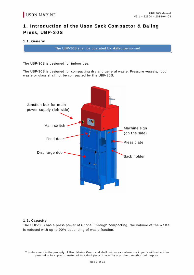
The UBP-30S is designed for indoor use. The UBP-30S is designed for compacting dry and general waste. Pressure vessels, food waste or glass shall not be compacted by the UBP-30S.
1.2. Capacity The UBP-30S has a press power of 6 tons. Through compacting, the volume of the waste is reduced with up to 90% depending of waste fraction.
The UBP-30S shall be operated by skilled personnel
Machine sign (on the side)
Feed door
Main switch
Discharge door
Junction box for main power supply (left side)
Sack holder
Press plate
UBP-30S Manual V5.1 – 22804 – 2014-04-03
This document is the property of Uson Marine Group and shall neither as a whole nor in parts without written permission be copied, transferred to a third party or used for any other unauthorized purpose.
Page 4 of 18
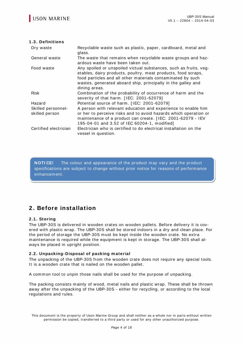
1.3. Definitions Dry waste Recyclable waste such as plastic, paper, cardboard, metal and
glass. General waste The waste that remains when recyclable waste groups and haz-
ardous waste have been taken out. Food waste Any spoiled or unspoiled victual substances, such as fruits, veg-
etables, dairy products, poultry, meat products, food scraps, food particles and all other materials contaminated by such wastes, generated aboard ship, principally in the galley and dining areas.
Risk Combination of the probability of occurrence of harm and the severity of that harm. [IEC: 2001-62079]
Hazard Potential source of harm. [IEC: 2001-62079] Skilled personnel-skilled person
A person with relevant education and experience to enable him or her to perceive risks and to avoid hazards which operation or maintenance of a product can create. [IEC: 2001-62079 - IEV 195-04-01 and 3.52 of IEC 60204-1, modified]
Certified electrician Electrician who is certified to do electrical installation on the vessel in question.
2. Before installation
2.1. Storing The UBP-30S is delivered in wooden crates on wooden pallets. Before delivery it is cov-ered with plastic wrap. The UBP-30S shall be stored indoors in a dry and clean place. For the period of storage the UBP-30S must be kept inside the wooden crate. No extra maintenance is required while the equipment is kept in storage. The UBP-30S shall al-ways be placed in upright position.
2.2. Unpacking-Disposal of packing material The unpacking of the UBP-30S from the wooden crate does not require any special tools. It is a wooden crate that is nailed on the wooden pallet. A common tool to unpin those nails shall be used for the purpose of unpacking. The packing consists mainly of wood, metal nails and plastic wrap. These shall be thrown away after the unpacking of the UBP-30S - either for recycling, or according to the local regulations and rules.
NOTICE! The colour and appearance of the product may vary and the product specifications are subject to change without prior notice for reasons of performance enhancement.
UBP-30S Manual V5.1 – 22804 – 2014-04-03
This document is the property of Uson Marine Group and shall neither as a whole nor in parts without written permission be copied, transferred to a third party or used for any other unauthorized purpose.
Page 5 of 18
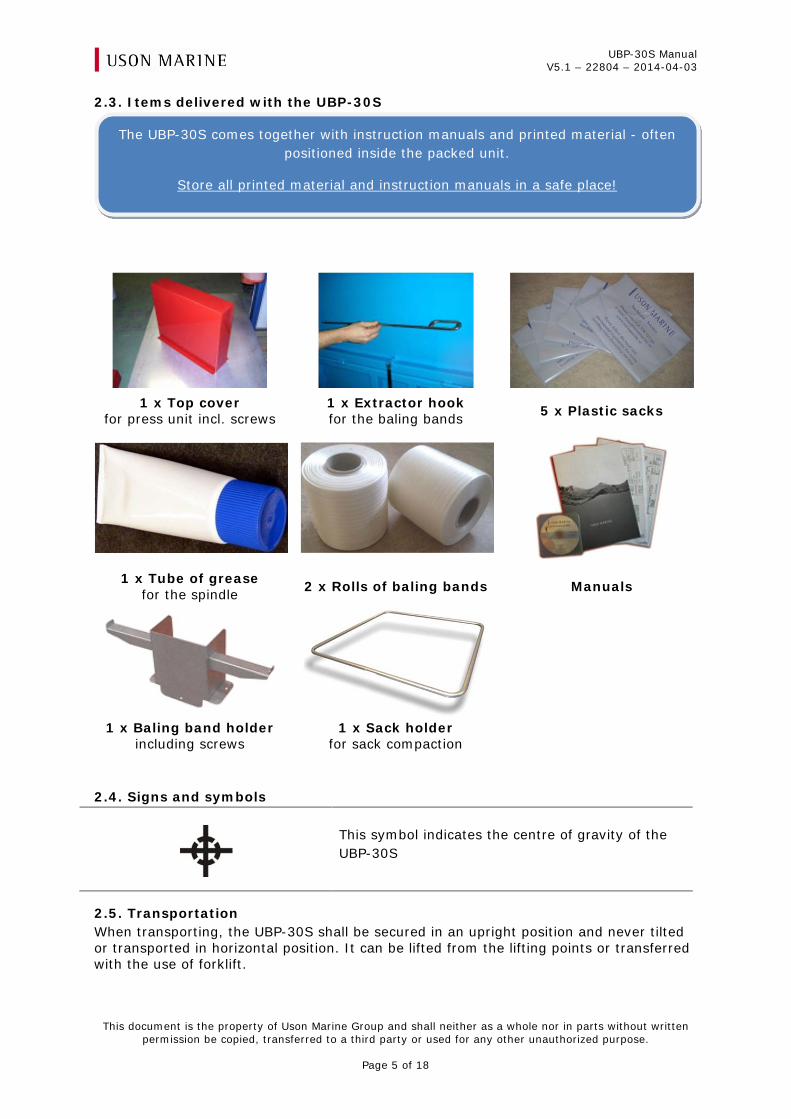
2.3. Items delivered with the UBP-30S
1 x Top cover
for press unit incl. screws 1 x Extractor hook for the baling bands 5 x Plastic sacks
1 x Tube of grease for the spindle 2 x Rolls of baling bands Manuals
1 x Baling band holder including screws
1 x Sack holder for sack compaction
2.4. Signs and symbols
This symbol indicates the centre of gravity of the UBP-30S
2.5. Transportation When transporting, the UBP-30S shall be secured in an upright position and never tilted or transported in horizontal position. It can be lifted from the lifting points or transferred with the use of forklift.
The UBP-30S comes together with instruction manuals and printed material - often positioned inside the packed unit.
Store all printed material and instruction manuals in a safe place!
UBP-30S Manual V5.1 – 22804 – 2014-04-03
This document is the property of Uson Marine Group and shall neither as a whole nor in parts without written permission be copied, transferred to a third party or used for any other unauthorized purpose.
Page 6 of 18
2.6. Firefighting equipment The UBP-30S consists of a big percentage of steel material. There is no special require-ment for extra fire fighting equipment to protect this unit, apart from the ones that are defined by the local regulations and rules for similar types of machinery.
2.7. Warranty The terms of the warranty and the warranty period is defined in the contractual terms between Uson Marine and the customer.
3. Installation
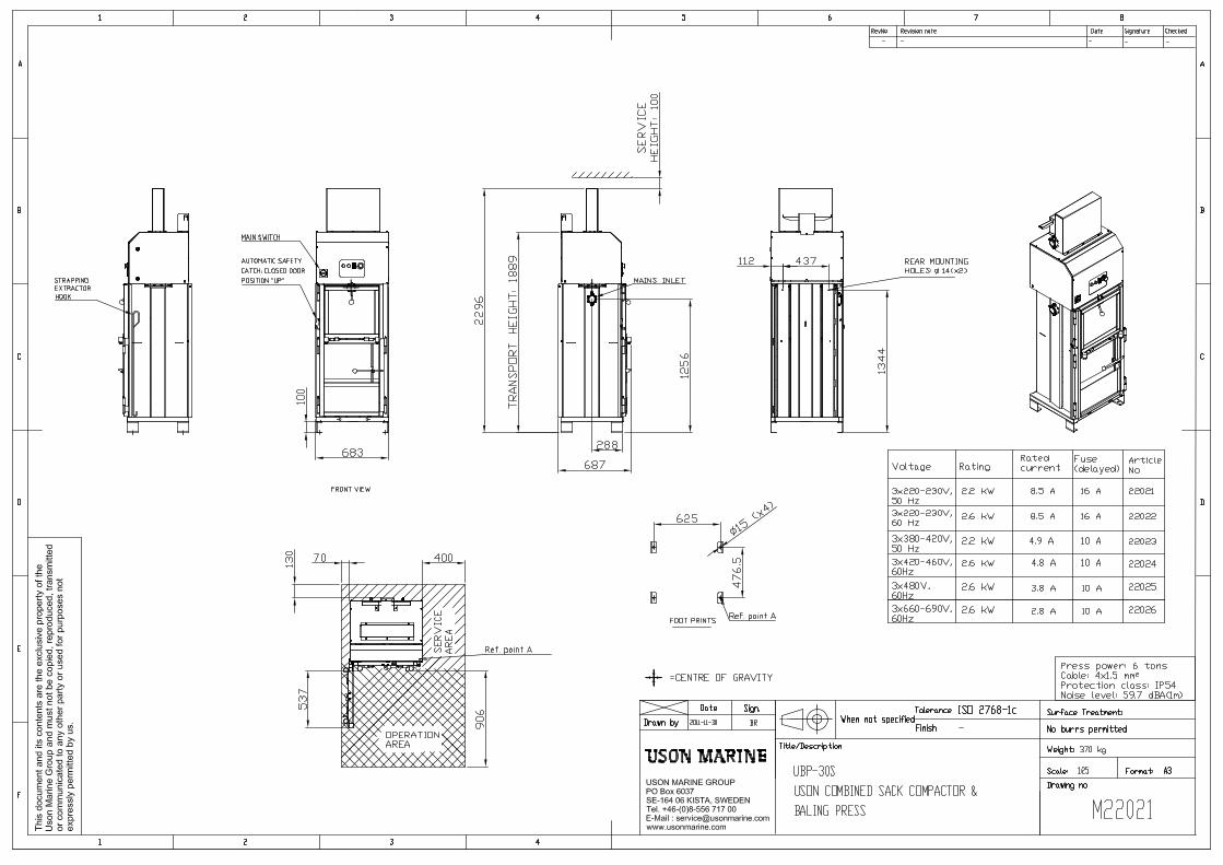
3.1. General For installation on deck, UBP-30S can be fastened using M12-bolts. There are also holes for rear mounting at the back of the UBP-30S. See manual drawing in appendix for de-tailed information. At delivery, the top cover for the press unit is placed inside the UBP-30S. Before the mains connection is made, this cover should be fitted on top of the press.
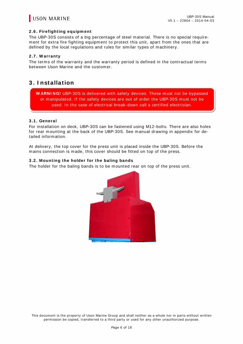
3.2. Mounting the holder for the baling bands The holder for the baling bands is to be mounted rear on top of the press unit.
WARNING! UBP-30S is delivered with safety devices. These must not be bypassed or manipulated. If the safety devices are out of order the UBP-30S must not be
used. In the case of electrical break-down call a certified electrician.
UBP-30S Manual V5.1 – 22804 – 2014-04-03
This document is the property of Uson Marine Group and shall neither as a whole nor in parts without written permission be copied, transferred to a third party or used for any other unauthorized purpose.
Page 7 of 18
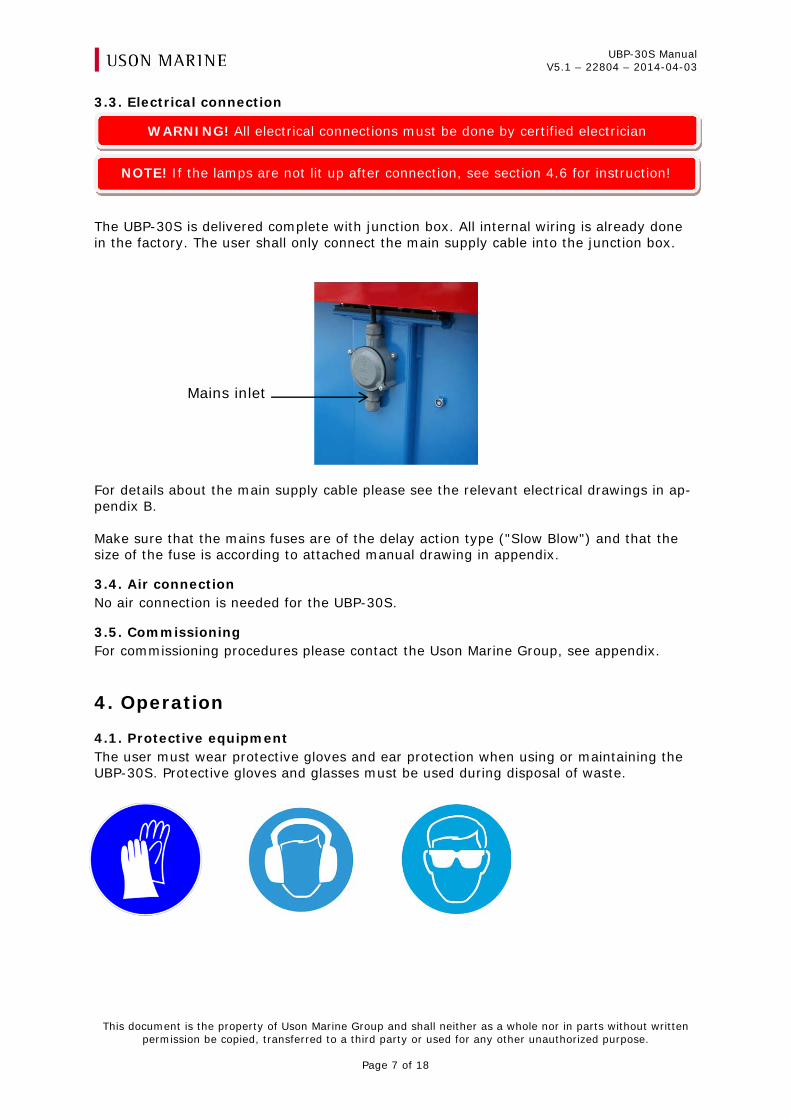
Mains inlet
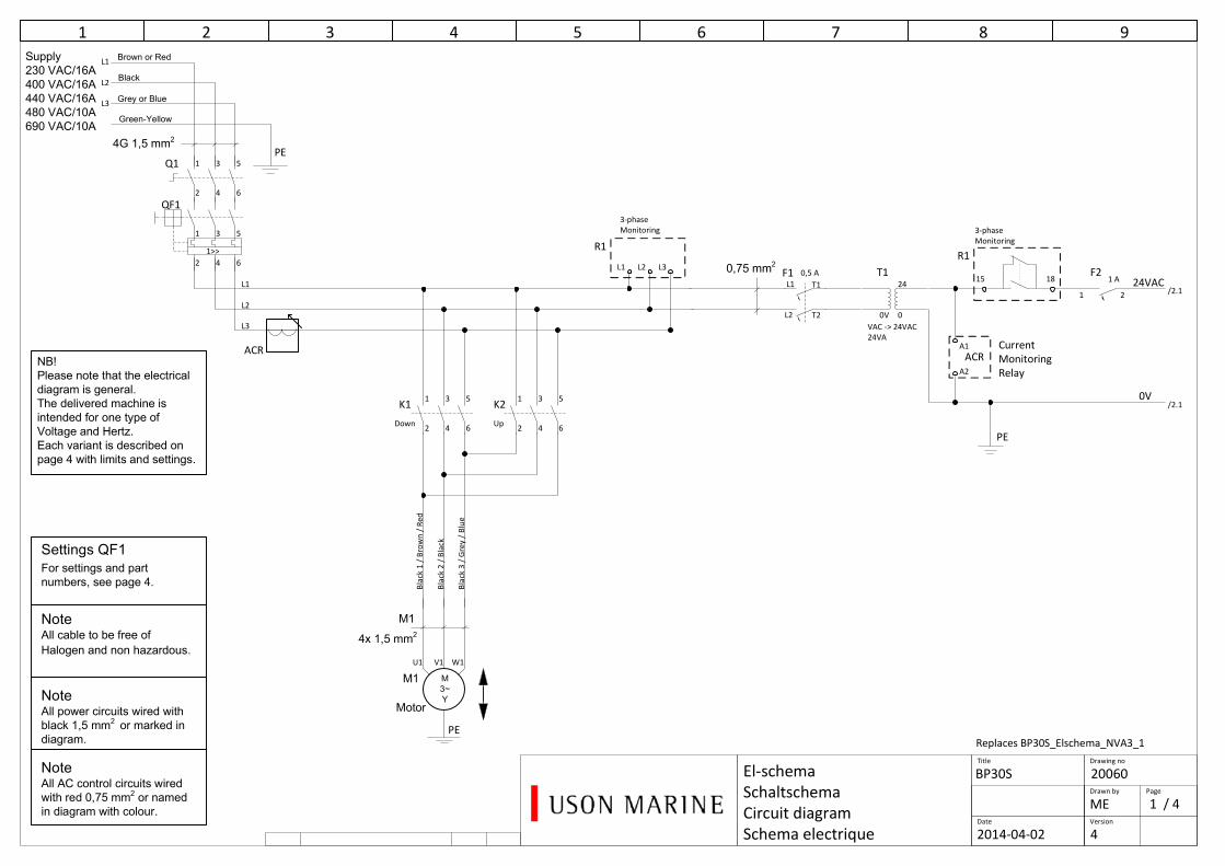
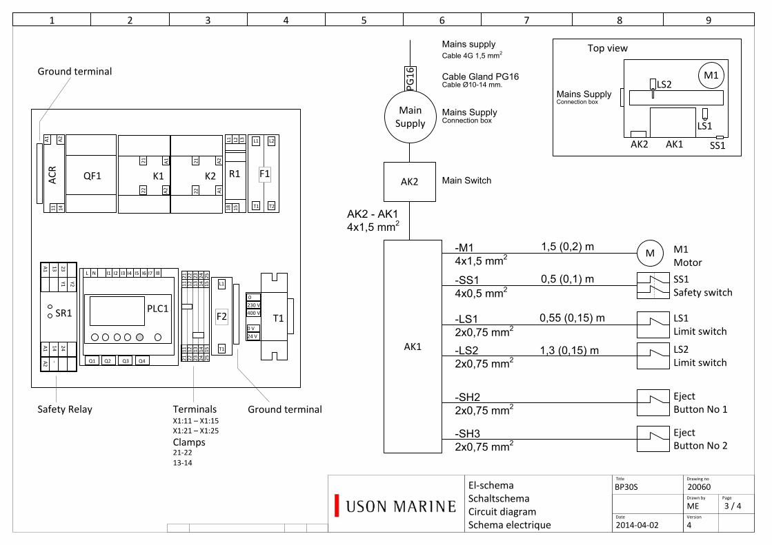
3.3. Electrical connection
The UBP-30S is delivered complete with junction box. All internal wiring is already done in the factory. The user shall only connect the main supply cable into the junction box.
For details about the main supply cable please see the relevant electrical drawings in ap-pendix B. Make sure that the mains fuses are of the delay action type ("Slow Blow") and that the size of the fuse is according to attached manual drawing in appendix.
3.4. Air connection No air connection is needed for the UBP-30S.
3.5. Commissioning For commissioning procedures please contact the Uson Marine Group, see appendix.
4. Operation
4.1. Protective equipment The user must wear protective gloves and ear protection when using or maintaining the UBP-30S. Protective gloves and glasses must be used during disposal of waste.
WARNING! All electrical connections must be done by certified electrician
NOTE! If the lamps are not lit up after connection, see section 4.6 for instruction!
UBP-30S Manual V5.1 – 22804 – 2014-04-03
This document is the property of Uson Marine Group and shall neither as a whole nor in parts without written permission be copied, transferred to a third party or used for any other unauthorized purpose.
Page 8 of 18
4.2. Safety 4.2.1. Emergency stop button The emergency stop button stops the UBP-30S immediately. Operation can also be inter-rupted by disturbances in the power supply. After a stop, the emergency stop button is released by pulling the knob out.
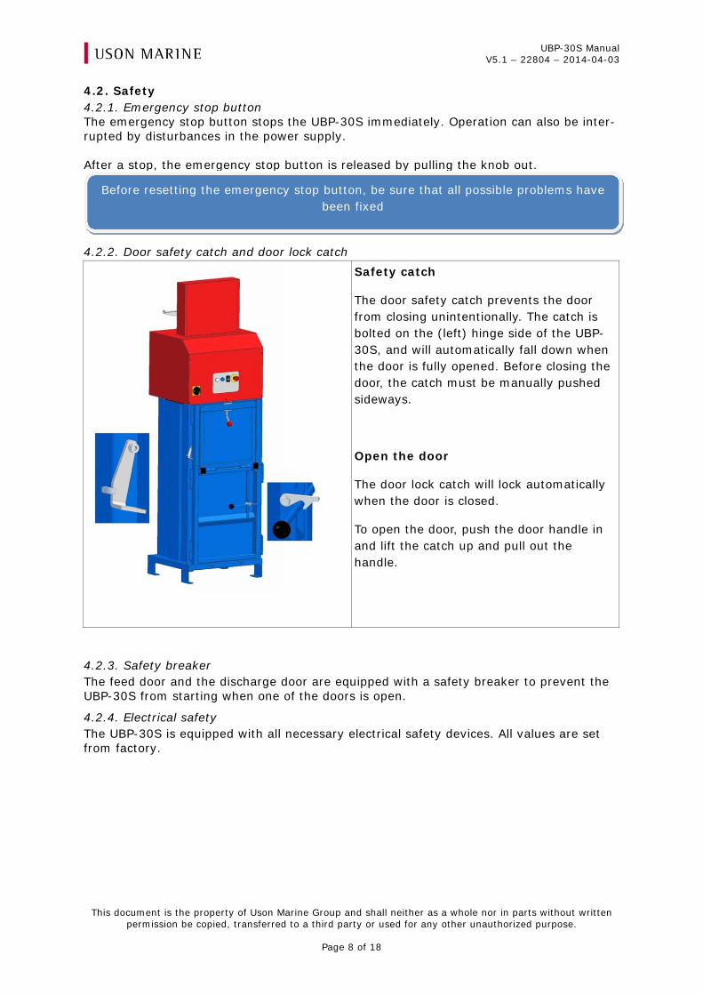
4.2.2. Door safety catch and door lock catch
Safety catch
The door safety catch prevents the door from closing unintentionally. The catch is bolted on the (left) hinge side of the UBP-30S, and will automatically fall down when the door is fully opened. Before closing the door, the catch must be manually pushed sideways.
Open the door
The door lock catch will lock automatically when the door is closed.
To open the door, push the door handle in and lift the catch up and pull out the handle.
4.2.3. Safety breaker The feed door and the discharge door are equipped with a safety breaker to prevent the UBP-30S from starting when one of the doors is open.
4.2.4. Electrical safety The UBP-30S is equipped with all necessary electrical safety devices. All values are set from factory.
Before resetting the emergency stop button, be sure that all possible problems have been fixed
UBP-30S Manual V5.1 – 22804 – 2014-04-03
This document is the property of Uson Marine Group and shall neither as a whole nor in parts without written permission be copied, transferred to a third party or used for any other unauthorized purpose.
Page 9 of 18
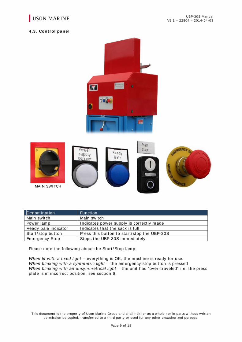
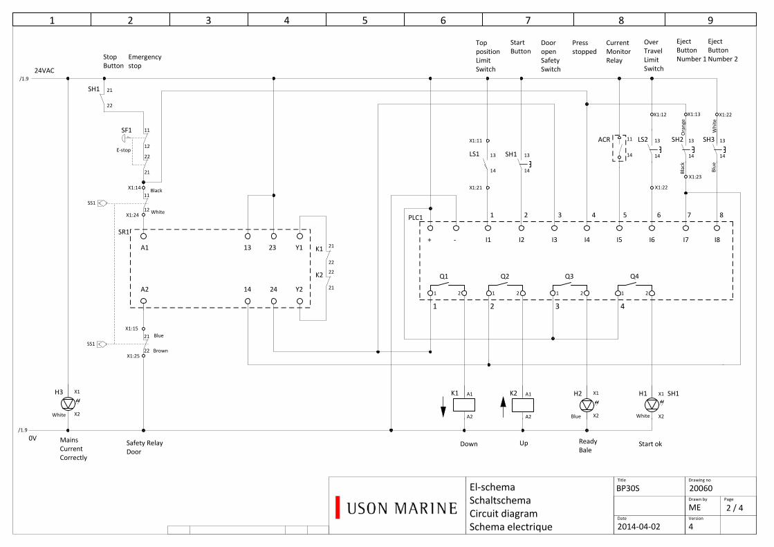
4.3. Control panel
Denomination Function Main switch Main switch Power lamp Indicates power supply is correctly made Ready bale indicator Indicates that the sack is full Start/stop button Press this button to start/stop the UBP-30S Emergency Stop Stops the UBP-30S immediately Please note the following about the Start/Stop lamp: When lit with a fixed light – everything is OK, the machine is ready for use. When blinking with a symmetric light – the emergency stop button is pressed When blinking with an unsymmetrical light – the unit has “over-traveled” i.e. the press plate is in incorrect position, see section 6.
MAIN SWITCH
UBP-30S Manual V5.1 – 22804 – 2014-04-03
This document is the property of Uson Marine Group and shall neither as a whole nor in parts without written permission be copied, transferred to a third party or used for any other unauthorized purpose.
Page 10 of 18
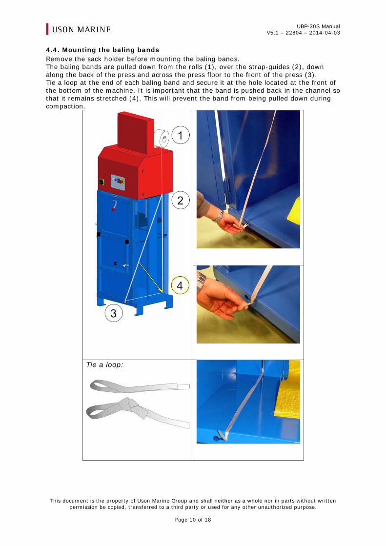
4.4. Mounting the baling bands Remove the sack holder before mounting the baling bands. The baling bands are pulled down from the rolls (1), over the strap-guides (2), down along the back of the press and across the press floor to the front of the press (3). Tie a loop at the end of each baling band and secure it at the hole located at the front of the bottom of the machine. It is important that the band is pushed back in the channel so that it remains stretched (4). This will prevent the band from being pulled down during compaction.
Tie a loop:
UBP-30S Manual V5.1 – 22804 – 2014-04-03
This document is the property of Uson Marine Group and shall neither as a whole nor in parts without written permission be copied, transferred to a third party or used for any other unauthorized purpose.
Page 11 of 18
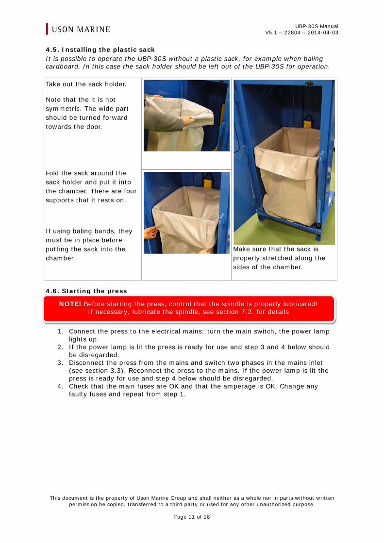
4.5. Installing the plastic sack It is possible to operate the UBP-30S without a plastic sack, for example when baling cardboard. In this case the sack holder should be left out of the UBP-30S for operation. Take out the sack holder.
Note that the it is not symmetric. The wide part should be turned forward towards the door.
Fold the sack around the sack holder and put it into the chamber. There are four supports that it rests on.
If using baling bands, they must be in place before putting the sack into the chamber.
Make sure that the sack is properly stretched along the sides of the chamber.
4.6. Starting the press
1. Connect the press to the electrical mains; turn the main switch, the power lamp lights up.
2. If the power lamp is lit the press is ready for use and step 3 and 4 below should be disregarded.
3. Disconnect the press from the mains and switch two phases in the mains inlet (see section 3.3). Reconnect the press to the mains. If the power lamp is lit the press is ready for use and step 4 below should be disregarded.
4. Check that the main fuses are OK and that the amperage is OK. Change any faulty fuses and repeat from step 1.
NOTE! Before starting the press, control that the spindle is properly lubricated! If necessary, lubricate the spindle, see section 7.2. for details
UBP-30S Manual V5.1 – 22804 – 2014-04-03
This document is the property of Uson Marine Group and shall neither as a whole nor in parts without written permission be copied, transferred to a third party or used for any other unauthorized purpose.
Page 12 of 18
4.7. Relocating / disconnecting the press If the press is to be moved the following check is recommended:
1. Before relocation, the press plate should be put in a position some 40 cm from the top. This will make for a safer transportation of the press.
2. Turn off the main switch and disconnect the press from the electrical mains supply. After reconnecting to the mains, repeat the procedure in section 4.6.
4.8. Operations cycle Load the waste into the press chamber through the feed door. When the chamber is filled, close the feed door and push the start button.
1. The press plate moves down and compacts the waste. a. If the chamber is filled up to such a level that the press plate meets the
required amount of resistance during compaction the press plate will return up approximately 200mm before again compacting the waste.
2. The press plate stops and returns automatically to its top position after a short delay.
3. Material loading can be resumed.
4.9. Stay-and-hold mode When the UBP-30S is not in use it should be placed in Stay-and-hold mode. This keeps the material in the chamber compacted under pressure and allows it to settle.
Press and hold the start button until the lamp flashes. o The press plate will now go down into the bottom position and remain
there, securing the waste in a compacted state. To resume normal operation press the start button and the press plate will return
to the top position.
4.10. Full sack/ready bale When the amount of waste material equals a full sack/ready bale the press plate stops in its lower position, holding the compacted waste together under pressure. This is indicated by activation of the ready bale indicator, a blue lamp. When the sack is full/bale is ready, it has to be strapped and removed without delay.
Notice! When moving the press, be wary of the high centre of gravity of the press!
When transported, the press should be secured in an upright position.
UBP-30S Manual V5.1 – 22804 – 2014-04-03
This document is the property of Uson Marine Group and shall neither as a whole nor in parts without written permission be copied, transferred to a third party or used for any other unauthorized purpose.
Page 13 of 18
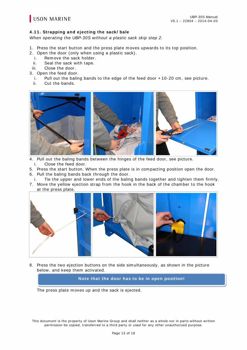
4.11. Strapping and ejecting the sack/bale When operating the UBP-30S without a plastic sack skip step 2.
1. Press the start button and the press plate moves upwards to its top position. 2. Open the door (only when using a plastic sack).
i. Remove the sack holder. ii. Seal the sack with tape. iii. Close the door.
3. Open the feed door. i. Pull out the baling bands to the edge of the feed door +10-20 cm, see picture. ii. Cut the bands.
4. Pull out the baling bands between the hinges of the feed door, see picture.
i. Close the feed door. 5. Press the start button. When the press plate is in compacting position open the door. 6. Pull the baling bands back through the door.
i. Tie the upper and lower ends of the baling bands together and tighten them firmly. 7. Move the yellow ejection strap from the hook in the back of the chamber to the hook
at the press plate.
8. Press the two ejection buttons on the side simultaneously, as shown in the picture
below, and keep them activated.
The press plate moves up and the sack is ejected.
Note that the door has to be in open position!
UBP-30S Manual V5.1 – 22804 – 2014-04-03
This document is the property of Uson Marine Group and shall neither as a whole nor in parts without written permission be copied, transferred to a third party or used for any other unauthorized purpose.
Page 14 of 18
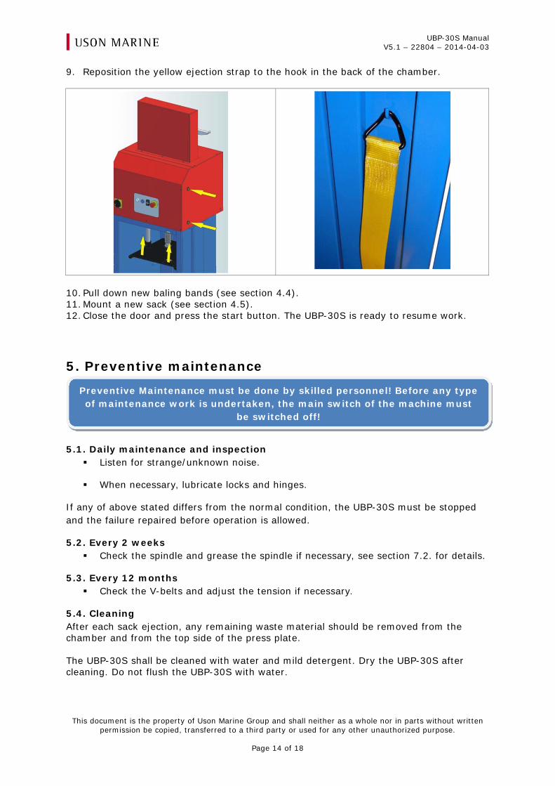
9. Reposition the yellow ejection strap to the hook in the back of the chamber.
10. Pull down new baling bands (see section 4.4). 11. Mount a new sack (see section 4.5). 12. Close the door and press the start button. The UBP-30S is ready to resume work.
5. Preventive maintenance
5.1. Daily maintenance and inspection Listen for strange/unknown noise.
When necessary, lubricate locks and hinges.
If any of above stated differs from the normal condition, the UBP-30S must be stopped and the failure repaired before operation is allowed.
5.2. Every 2 weeks Check the spindle and grease the spindle if necessary, see section 7.2. for details.
5.3. Every 12 months Check the V-belts and adjust the tension if necessary.
5.4. Cleaning After each sack ejection, any remaining waste material should be removed from the chamber and from the top side of the press plate. The UBP-30S shall be cleaned with water and mild detergent. Dry the UBP-30S after cleaning. Do not flush the UBP-30S with water.
Preventive Maintenance must be done by skilled personnel! Before any type of maintenance work is undertaken, the main switch of the machine must
be switched off!
UBP-30S Manual V5.1 – 22804 – 2014-04-03
This document is the property of Uson Marine Group and shall neither as a whole nor in parts without written permission be copied, transferred to a third party or used for any other unauthorized purpose.
Page 15 of 18
6. Trouble shooting
Fault Possible cause Remedy
Motor does not start, the power lamp (white) is not lit
The main switch is not “ON” Turn the main switch on
There is not voltage supplied on all phases or the phases are switched
Check the power supply. This must be done by a certified electrician!
The fuse in the control panel has tripped
Check the fuse F1 and F2 on the elec-trical diagram. Reset fuse if necessary
Motor does not start, the power lamp (white) lamp is lit but the start/stop button is not lit
Feed door/Discharge door is open
Close the open door
Motor does not start, the power lamp (white) lamp is lit and the start/stop button is flashing symmetrical
The emergency stop has been pushed
Release the emergency stop
Motor does not start, the power lamp (white) lamp is lit and the start/stop button is flashing asymmetrically
Over-travel protection Check that the machine is run on the correct frequency. If incorrect then contact Uson Marine, see appendix C Check if waste material is affecting the limit switch, located behind the control box.
The motor starts, the press plate does not move
The V-belts slip Waste material rests on the top of the press plate prevent-ing the press plate from mov-ing to its top position
Adjust the tension of the V-belts or change the V-belts (all 3 V-belts) if they are worn out Make sure the V-belts are clean and that they are free from grease Contact Uson Marine, see appendix C
The weight of the bale is low
The V-belts slip Adjust the tension of the V-belts or change the V-belts (all 3 V-belts) if they are worn out Make sure the V-belts are clean and that they are free from grease
The press plate does not re-turn and the ready bale indi-cator is not lit
Blue LED lamp is out of order Change the blue LED lamp
Ready bale indicator flashes Bale size exceeded Remove part of the material and re-sume the operation of the UBP-30S
Trouble shooting must be done by skilled personnel! Before any type of maintenance work is undertaken, the main switch of the UBP-30S must be
switched off!
UBP-30S Manual V5.1 – 22804 – 2014-04-03
This document is the property of Uson Marine Group and shall neither as a whole nor in parts without written permission be copied, transferred to a third party or used for any other unauthorized purpose.
Page 16 of 18
7. Corrective Maintenance
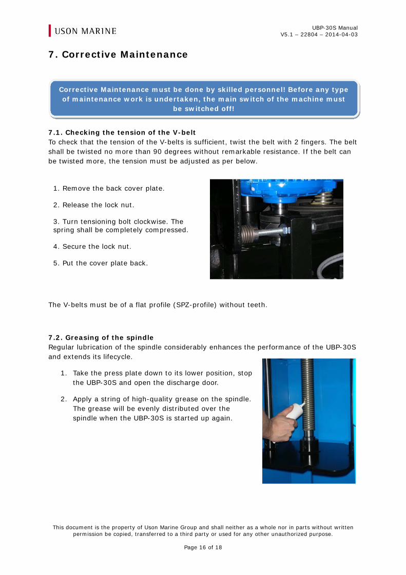
7.1. Checking the tension of the V-belt To check that the tension of the V-belts is sufficient, twist the belt with 2 fingers. The belt shall be twisted no more than 90 degrees without remarkable resistance. If the belt can be twisted more, the tension must be adjusted as per below.
The V-belts must be of a flat profile (SPZ-profile) without teeth.
7.2. Greasing of the spindle Regular lubrication of the spindle considerably enhances the performance of the UBP-30S and extends its lifecycle.
1. Take the press plate down to its lower position, stop the UBP-30S and open the discharge door.
2. Apply a string of high-quality grease on the spindle. The grease will be evenly distributed over the spindle when the UBP-30S is started up again.
Corrective Maintenance must be done by skilled personnel! Before any type of maintenance work is undertaken, the main switch of the machine must
be switched off!
1. Remove the back cover plate. 2. Release the lock nut. 3. Turn tensioning bolt clockwise. The spring shall be completely compressed. 4. Secure the lock nut. 5. Put the cover plate back.
UBP-30S Manual V5.1 – 22804 – 2014-04-03
This document is the property of Uson Marine Group and shall neither as a whole nor in parts without written permission be copied, transferred to a third party or used for any other unauthorized purpose.
Page 17 of 18
8. Spare parts and consumables
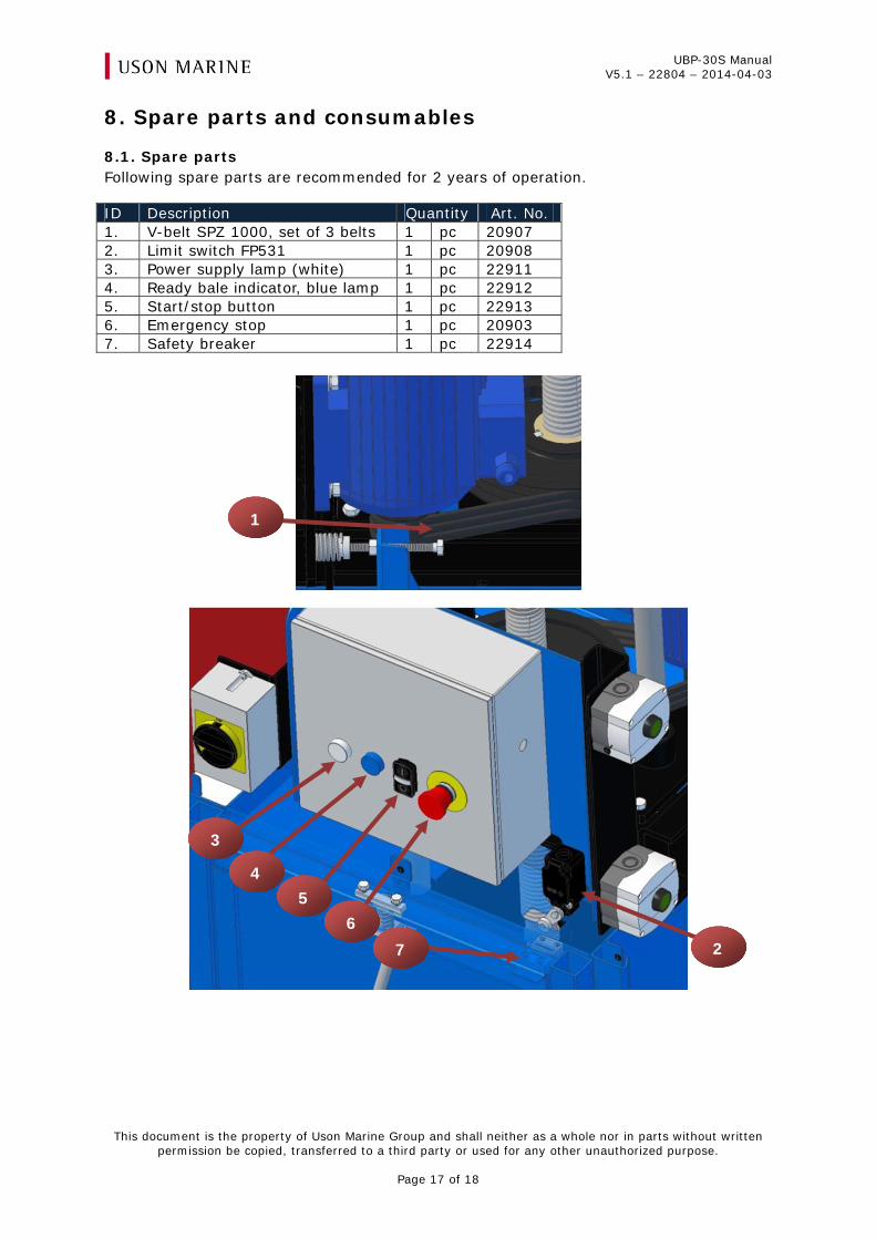
8.1. Spare parts Following spare parts are recommended for 2 years of operation.
ID Description Quantity Art. No. 1. V-belt SPZ 1000, set of 3 belts 1 pc 20907 2. Limit switch FP531 1 pc 20908 3. Power supply lamp (white) 1 pc 22911 4. Ready bale indicator, blue lamp 1 pc 22912 5. Start/stop button 1 pc 22913 6. Emergency stop 1 pc 20903 7. Safety breaker 1 pc 22914
1
2
3
4 5
67
UBP-30S Manual V5.1 – 22804 – 2014-04-03
This document is the property of Uson Marine Group and shall neither as a whole nor in parts without written permission be copied, transferred to a third party or used for any other unauthorized purpose.
Page 18 of 18
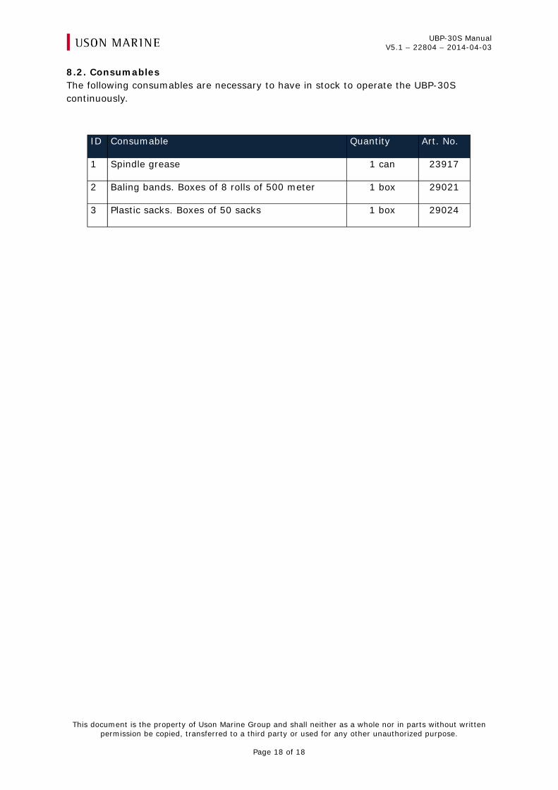
8.2. Consumables The following consumables are necessary to have in stock to operate the UBP-30S continuously.
ID Consumable Quantity Art. No.
1 Spindle grease 1 can 23917
2 Baling bands. Boxes of 8 rolls of 500 meter 1 box 29021
3 Plastic sacks. Boxes of 50 sacks 1 box 29024
UBP-30S Manual V5.1 – 22804
APPENDIX A
Manual drawing
UBP-30S Manual V5.1 – 22804
APPENDIX B
Electrical drawing
El-schema
Schaltschema
Circuit diagram
Schema electrique
1 2 3 4 5 6 7 8 9
1 / 4
PE4G 1,5 mm2
Black
Grey or Blue
Brown or RedSupply
230 VAC/16A
400 VAC/16A
440 VAC/16A
480 VAC/10A
690 VAC/10A
Q1 1 3 5
2 4 6
ACR
K11 3 5
Down4 6
1 3 5
2 4 6
K2
Up2
4x 1,5 mm2
M1
M
3~
Y
M1
Motor
PE
PE
24VAC
R1
15
3-phase
Monitoring
18
1 2
F21 A
F1
L2
L1
T2
T1
0,5 A
Bla
ck 3
/ G
rey
/ B
lue
Bla
ck 2
/ B
lack
Bla
ck 1
/ B
row
n /
Re
d
NoteAll AC control circuits wired
with red 0,75 mm2
or named
in diagram with colour.
NoteAll power circuits wired with
black 1,5 mm2
or marked in
diagram.
/2.1
0,75 mm2
L1
L2
0V/2.1
L3
QF1
1>>
1 3 5
2 4 6
Current
Monitoring
Relay
ACR
A2
A1
T1
0V 0
VAC -> 24VAC
24VA
24
NoteAll cable to be free of
Halogen and non hazardous.
Green-Yellow
R1
L1
3-phase
Monitoring
L2 L3
L1
L2
L3
U1 V1 W1
For settings and part
numbers, see page 4.
Settings QF1
NB!
Please note that the electrical
diagram is general.
The delivered machine is
intended for one type of
Voltage and Hertz.
Each variant is described on
page 4 with limits and settings.
Date
Drawing no
Drawn by
Version
Page
ME
2014-04-02
Title
20060BP30S
4
Replaces BP30S_Elschema_NVA3_1
El-schema
Schaltschema
Circuit diagram
Schema electrique
1 2 3 4 5 6 7 8 9
2 / 4
24VAC
0V
21
K1 A1
A2
K2 A1
A2
H1
White
-+ I6I5I4I3I2I1 I7 I8
Q3Q2Q1 Q4
1 2 1 2 1 2 1 2
K1
K2
22
21
22
13SH1
14
13LS1
14
ACR 11
14
13LS2
14
SF1
12
22
21
E-stop
11
21SH1
22
Stop
Button
Emergency
stop
Top
position
Limit
Switch
Start
Button
Door
open
Safety
Switch
Press
stopped
Current
Monitor
Relay
UpDown Start ok
Over
Travel
Limit
Switch
SR1
PLC1
X1:21
X1:11
Blue
/1.9
/1.9
1 2 3 4
1 2 3 4 5 6 8
A1
A2
13 Y123
14 Y224
Brown
White
Black
SS1
X1:14
X1:24
11
12
SS1
X1:15
X1:25
21
22
H3
White
Mains
Current
Correctly
Eject
Button
Number 1
13SH2
14
13SH3
14
Eject
Button
Number 2
7
Ora
ng
e
X1:13
Bla
ck
Blu
e
X1:22
Date
Drawing no
Drawn by
Version
Page
ME
2014-04-02
Title
20060BP30S
4
X1
X2
X1
X2
X1:23
X1:12
Wh
ite
X1:22
H2
Blue
X1
X2
Ready
BaleSafety Relay
Door
SH1
El-schema
Schaltschema
Circuit diagram
Schema electrique
1 2 3 4 5 6 7 8 9
3 / 4
Ground terminal
Ground terminalTerminalsX1:11 – X1:15
X1:21 – X1:25
Clamps21-22
13-14
AK1
AK2
-SS1
4x0,5 mm2
-LS1
2x0,75 mm2
-LS2
2x0,75 mm2
0,5 (0,1) m
0,55 (0,15) m
1,3 (0,15) m
AK2 - AK14x1,5 mm2
SS1
Safety switch
LS1
Limit switch
LS2
Limit switch
K1 K2
21
22
A2
A1
21
22
A2
A1
AC
R1
1
14
A1
A2
T1
230 V
0
400 V
0 V
24 V
L1
T1
F2
F1
T1 T2
L1 L2
R1
18
15
L2L1 L3
SR1
Y2
Y1
23
13
A1
24
-1
4
A2
A1
Safety Relay
QF1
PLC1
L N
Q2 Q3 Q4Q1
I1 I8I2 I3 I4 I5 I7I6
M1
SS1
LS1
LS2
Top view
-M1
4x1,5 mm2
1,5 (0,2) m M1
MotorM
13
14
24
11
21
23
24
21
13
14
11
12
22
12
23
22
Date
Drawing no
Drawn by
Version
Page
ME
2014-04-02
Title
20060BP30S
4
25
15
15
25
PG
16
Mains SupplyConnection box
Main
Supply
Cable Gland PG16Cable Ø10-14 mm.
Mains SupplyConnection box
AK1AK2
Main Switch
-SH3
2x0,75 mm2
-SH2
2x0,75 mm2
Eject
Button No 1
Eject
Button No 2
Mains supply
Cable 4G 1,5 mm2
El-schema
Schaltschema
Circuit diagram
Schema electrique
ME
1 2 3 4 5 6 7 8 9
4 / 4
Led lamp
Mains
connected
correctly
Led lamp
Ready
bale
Emergency
stop push
button
Led lamp -
Ready for use
Push button
start/stop
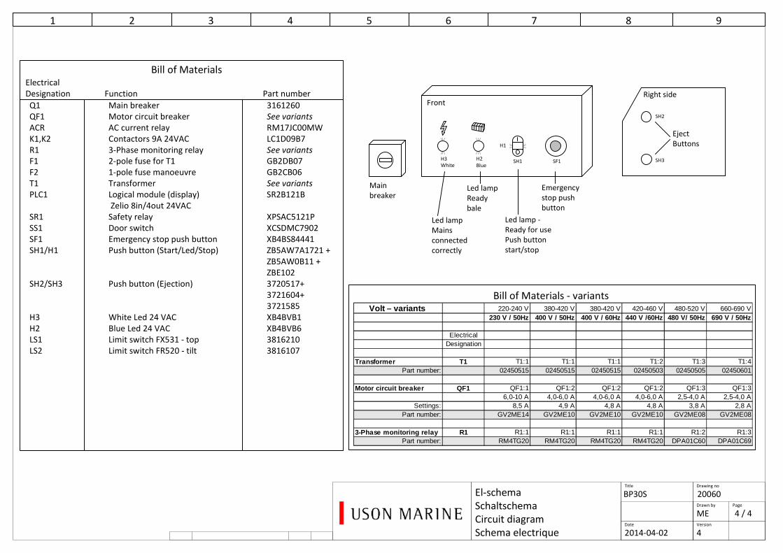
Bill of MaterialsElectrical
Designation Function Part number
Q1 Main breaker 3161260
QF1 Motor circuit breaker See variants
ACR AC current relay RM17JC00MW
K1,K2 Contactors 9A 24VAC LC1D09B7
R1 3-Phase monitoring relay See variants
F1 2-pole fuse for T1 GB2DB07
F2 1-pole fuse manoeuvre GB2CB06
T1 Transformer See variants
PLC1 Logical module (display) SR2B121B
Zelio 8in/4out 24VAC
SR1 Safety relay XPSAC5121P
SS1 Door switch XCSDMC7902
SF1 Emergency stop push button XB4BS84441
SH1/H1 Push button (Start/Led/Stop) ZB5AW7A1721 +
ZB5AW0B11 +
ZBE102
SH2/SH3 Push button (Ejection) 3720517+
3721604+
3721585
H3 White Led 24 VAC XB4BVB1
H2 Blue Led 24 VAC XB4BVB6
LS1 Limit switch FX531 - top 3816210
LS2 Limit switch FR520 - tilt 3816107
Main
breaker
H2SF1SH1H3
BlueWhite
Front
Bill of Materials - variants
Date
Drawing no
Drawn by
Version
Page
2014-04-02
Title
20060BP30S
4
H1
SH2
SH3
Eject
Buttons
Right side
Volt – variants 220-240 V 380-420 V 380-420 V 420-460 V 480-520 V 660-690 V230 V / 50Hz 400 V / 50Hz 400 V / 60Hz 440 V /60Hz 480 V/ 50Hz 690 V / 50Hz
ElectricalDesignation
Transformer T1 T1:1 T1:1 T1:1 T1:2 T1:3 T1:4Part number: 02450515 02450515 02450515 02450503 02450505 02450601
Motor circuit breaker QF1 QF1:1 QF1:2 QF1:2 QF1:2 QF1:3 QF1:36,0-10 A 4,0-6,0 A 4,0-6,0 A 4,0-6,0 A 2,5-4,0 A 2,5-4,0 A
Settings: 8,5 A 4,9 A 4,8 A 4,8 A 3,8 A 2,8 APart number: GV2ME14 GV2ME10 GV2ME10 GV2ME10 GV2ME08 GV2ME08
3-Phase monitoring relay R1 R1:1 R1:1 R1:1 R1:1 R1:2 R1:3Part number: RM4TG20 RM4TG20 RM4TG20 RM4TG20 DPA01C60 DPA01C69

UBP-30S Manual V5.1 – 22804
APPENDIX C
Customer contact
Service Agreements» Commissioning
» Training» Preventative Maintenance support
Service support » Technical documentation
» Spare parts» Consumables
Continuous improvements» System upgrades
» Engineering support» Audits/ Surveys
Garbage Management Plan
Rental and leasing
Contact for Service & Support:Phone: +46 8 556 717 20
E-mail: [email protected]
www.usonmarine.com
effective waste management demonstrates environmental responsibility!
About Uson Marine GroupUson Marine is a leading provider of sustainable and environmentally friendly waste management
systems for the maritime & offshore industry. By using our wide knowledge and experience we assist our clients in complying with current and future regulations, whilst at the same time improving their
environmental image and reducing their cost for handling of ship-generated garbage.
Uson Marine Group is located in Sweden, Finland, Norway, The Netherlands and USA.
Uson Marine has more than 25 years of experience of waste management in the maritime industry. We custom-make our services and systems for different type of installation and applications,
and can provide worldwide service through our network of representatives.
We can assist in each stage of the process from design to installation, surveys, commissioning and training of the crew.
Service & Support
UBP-30S Manual V5.1 – 22804
APPENDIX D
DNV Verification Report
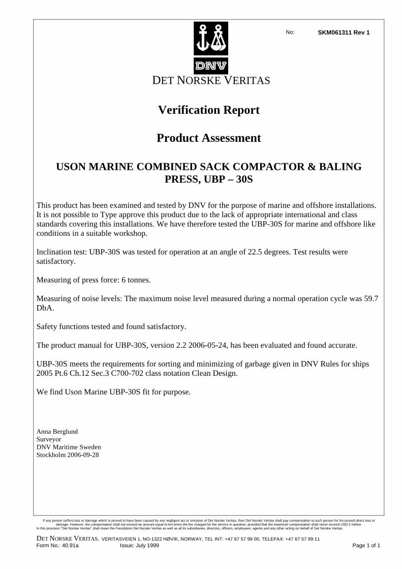
No: SKM061311 Rev 1
DET NORSKE VERITAS
Verification Report
Product Assessment
USON MARINE COMBINED SACK COMPACTOR & BALING PRESS, UBP – 30S
This product has been examined and tested by DNV for the purpose of marine and offshore installations. It is not possible to Type approve this product due to the lack of appropriate international and class standards covering this installations. We have therefore tested the UBP-30S for marine and offshore like conditions in a suitable workshop. Inclination test: UBP-30S was tested for operation at an angle of 22.5 degrees. Test results were satisfactory. Measuring of press force: 6 tonnes. Measuring of noise levels: The maximum noise level measured during a normal operation cycle was 59.7 DbA. Safety functions tested and found satisfactory. The product manual for UBP-30S, version 2.2 2006-05-24, has been evaluated and found accurate. UBP-30S meets the requirements for sorting and minimizing of garbage given in DNV Rules for ships 2005 Pt.6 Ch.12 Sec.3 C700-702 class notation Clean Design. We find Uson Marine UBP-30S fit for purpose. Anna Berglund Surveyor DNV Maritime Sweden Stockholm 2006-09-28
If any person suffers loss or damage which is proved to have been caused by any negligent act or omission of Det Norske Veritas, then Det Norske Veritas shall pay compensation to such person for his proved direct loss or
damage. However, the compensation shall not exceed an amount equal to ten times the fee charged for the service in question, provided that the maximum compensation shall never exceed USD 2 million. In this provision "Det Norske Veritas" shall mean the Foundation Det Norske Veritas as well as all its subsidiaries, directors, officers, employees, agents and any other acting on behalf of Det Norske Veritas.
DET NORSKE VERITAS, VERITASVEIEN 1, NO-1322 HØVIK, NORWAY, TEL INT: +47 67 57 99 00, TELEFAX: +47 67 57 99 11 Form No.: 40.91a Issue: July 1999 Page 1 of 1