manual a
TRANSCRIPT

2N® Helios IP Door Intercom
Configuration Manual Version 1.15.4
Firmware 1.15.4 www.2n.cz

The 2N TELEKOMUNIKACE a.s. joint-stock company is a Czech manufacturer and supplier
of telecommunications equipment.
The product family developed by 2N TELEKOMUNIKACE a.s. includes GSM gateways,
private branch exchanges (PBX), and door and lift communicators.
2N TELEKOMUNIKACE a.s. has been ranked among the Czech top companies for years
and represented a symbol of stability and prosperity on the telecommunications market
for almost two decades. At present, we export our products into over 120 countries
worldwide and have exclusive distributors on all continents.
2N® is a registered trademark of 2N TELEKOMUNIKACE a.s.. Any product and/or other
names mentioned herein are registered trademarks and/or trademarks or brands
protected by law.
2N TELEKOMUNIKACE administers the FAQ database to help you quickly find information and to answer your questions about 2N products and services. On faq.2n.cz you can find
information regarding products adjustment and instructions for optimum use and
procedures „What to do if...“.
Declaration of Conformity
2N TELEKOMUNIKACE a.s. hereby declares that the 2N® Helios product complies with all
basic requirements and other relevant provisions of the 1999/5/EC directive. For the full
wording of the Declaration of Conformity see the CD-ROM enclosed and at www.2n.cz.
The 2N TELEKOMUNIKACE company is a holder of the ISO 9001:2008 certificate. All
development, production and distribution processes of the company are managed by this
standard and guarantee a high quality and advanced technical level of and a professional
approach to all of our products.

Contents
1. Product Overview............................................................... 5
1.1 Product Description ....................................................................................................... 6
Basic Features.................................................................................................................. 6
Advantages of Use ........................................................................................................... 6
1.2 Terms and Symbols Used ............................................................................................. 8
Manual Symbols ............................................................................................................... 8
2. 2N® Helios IP Configuration .............................................. 9
2.1 Model Overview ............................................................................................................ 10
2.2 Quick Configuration for Calling .................................................................................. 12
Language Selection ........................................................................................................ 12
Network Settings ............................................................................................................ 12
Static Parameter Setting ................................................................................................ 12
SIP Parameter Setting .................................................................................................... 13
Telephone Directory Setting ........................................................................................... 14
Switch Setting ................................................................................................................. 15
2.3 Configuration ................................................................................................................ 16
IP Address Obtaining from DHCP .................................................................................. 16
Manual IP Address Setting ............................................................................................. 16
Description of 2N® Helios IP Network Scanner .............................................................. 17
Login ............................................................................................................................... 18
Language Selection ........................................................................................................ 18
Information ...................................................................................................................... 19
Telephone Directory ....................................................................................................... 21
Profiles ............................................................................................................................ 24
Switches ......................................................................................................................... 26
Network .......................................................................................................................... 29
Date and Time ................................................................................................................ 32
SIP Settings .................................................................................................................... 34
Administration Web Server ............................................................................................. 37
Audio .............................................................................................................................. 39
Video .............................................................................................................................. 41
Audio Codecs ................................................................................................................. 43
Video Codecs ................................................................................................................. 45
Streaming ....................................................................................................................... 47
Auto Update .................................................................................................................... 53
Display ............................................................................................................................ 55
System Log ..................................................................................................................... 57

E-Mail ............................................................................................................................. 58
Multicast ......................................................................................................................... 61
Miscellaneous ................................................................................................................. 63
RFID Card Reader ......................................................................................................... 66
RFID Card Reader – Module Settings ........................................................................... 68
RFID Card Reader – Installed Cards ............................................................................. 70
RFID Card Reader – Access Log ................................................................................... 71
Tools ............................................................................................................................... 72
Configuration .................................................................................................................. 73
Display Program ............................................................................................................. 75
Firmware ......................................................................................................................... 76
User Sounds ................................................................................................................... 77
Certificates ...................................................................................................................... 79
Network Trace ................................................................................................................ 81
Licence ........................................................................................................................... 82
Signalling of Operational Statuses ................................................................................. 84
2.4 List of Figures ............................................................................................................... 86
2.5 List of Tables ................................................................................................................ 88

5
1
1. Product Overview
In this section, we introduce the 2N® Helios IP product, outline its application options
and highlight the advantages following from its use.
Here is what you can find in this section:
Product Description
Terms and Symbols Used

Product Description 1.1
6
1.1 Product Description
Basic Features
The 2N® Helios IP door intercoms are capable of replacing the traditional doorbell
button panel with a speakerphone and the entire system of wiring, bells and intercom
installations in buildings where structured cabling is installed. Their installation is very
easy, all you need is connect it to the other LAN elements using a twisted UTP cable.
By pressing any of the quick dial buttons, 2N® Helios IP will set up a call to the
number that had been stored in the respective memory. The number of buttons (in
some models) can be extended up to 54 using 8-button or 16-button extending
modules.
Thanks to an integrated scheduler it is possible to configure each of the buttons in
such a way that the called party is always available.
It is possible to define up to three telephone numbers for each of the buttons,
between which 2N® Helios IP switches at absence.
Beside the buttons, you can also use the numeric keypad, which also serves as a code
lock. With the use of this keypad you can also use the system as a button telephone.
The keypad can be combined with the quick dialling buttons.
2N® Helios IP supports video streaming. This function allows the user to scan the area
in front of the 2N® Helios IP camera. Thus, 2N® Helios IP provides better and broader
services than a standard house intercom systems. Thanks to the integrated SIP
protocol it can make use of all VoIP services, call forwarding at absence (to another
office, to the VoiceMail system or a cellular phone) or call switching (from the
secretary’s office to a specific person, e.g.).
In addition, 2N® Helios IP includes a switch that helps you control the electric lock
from any VoIP telephone (by entering the code using tone dialling).
Advantages of Use
Works in the Ethernet network
Power supply over Ethernet – PoE
SIP communication protocol
Integrated web server for configuration
Up to 54 quick dialling buttons
Up to 999 users / user groups
Video (camera-equipped models) streaming
Display of information (display-equipped models)
Integrated scheduler with day/night/weekend modes
Can be used as a standard VoIP telephone and a code lock (keypad-equipped
models)

Product Description 1.1
7
Modular system – up to 54 buttons + keypad
DTMF according to RFC2833, in-band

Terms and Symbols Used 1.2
8
1.2 Terms and Symbols Used
Manual Symbols
Safety
Always abide by this information to prevent injury of persons.
Warning
Always abide by this information to prevent damage to the device.
Caution
Important information for system functionality.
Tip
Useful advice.
Note
Additional information.

9
2
2. 2N® Helios IP
Configuration
This section describes the 2N® Helios IP configuration.
Here is what you can find in the section:
Quick Configuration for Calling
Configuration

Model Overview 2.1
10
2.1 Model Overview
The table below includes the properties and functions of the available 2N® Helios IP
models.
Property/Model Helios IP
Vario Helios IP
Force Helios IP
Safety Helios IP
Uni
Part No. 9137…. 9151… 9152… 9153…
Integrated camera optional optional optional no
Wide-angle lens no yes yes no
Integrated microphone and loudspeaker yes yes yes yes
Two integrated microphones no yes yes no
Count of basic unit buttons 1, 3 or 6 1, 2 or 4 1 1 or 2
Extended count of buttons (extenders) yes (up to 48) no no no
Numerical keypad optional optional no no
Internal RFID card reader optional optional no no
Display optional no no no
Standard switch yes yes yes yes
Additional switch optional optional optional no
Digital input optional optional optional no
Adaptive volume control no yes yes yes
Standard amplifier output 150mW 1W 1W 1W
Extended amplifier output ( 10W) no yes yes yes
PoE 802.3af power supply yes yes yes yes
12V DC power supply yes yes yes yes
Tamper switch no optional optional yes
Backlit buttons no yes yes yes
Backlit name plates yes yes no yes
Count of telephone directory entries 54/999 54/999 3 2
Count of telephone numbers per user 3 3 3 3
Substitute if inaccessible no/yes no/yes no/yes no
User activation/deactivation no/yes no/yes no/yes no
Count of controlled switches 2/4 2/4 2/4 2/4
Count of universal switch codes 2/10 2/10 2/10 2/10
User switch codes in telephone directory no/yes no/yes no/yes no/yes
Extended switch setting options no/yes no/yes no/yes no/yes
HTTP switch control option no/yes no/yes no/yes no/yes

Model Overview 2.1
11
Property/Model Helios IP
Vario Helios IP
Force Helios IP
Safety Helios IP
Uni
User profiles yes yes yes yes
Count of user profiles 3/20 3/20 3/20 3/20
External camera support no/yes no/yes no/yes no/yes
JPEG/MJPEG http video yes yes yes no
2N Helios IP Eye support yes yes yes no
Audio/video streaming (RTSP Server) no/yes no/yes no/yes no
E-mail sending (SMTP Client) no/yes no/yes no/yes no
Telephone mode yes yes no no
User defined sounds no/yes no/yes no/yes no/yes
Automatic update (TFTP Client) no/yes no/yes no/yes no/yes
802.1x support no/yes no/yes no/yes no/yes Table 2.1 Model Overview
The values behind the slash (54/999, e.g.) are applied only if the licence key
(professional 2N® Helios IP licence) is inserted.

Quick Configuration for Calling 2.2
12
2.2 Quick Configuration for Calling
This subsection describes the most common and convenient way of configuration. For
details on the configuration parameters refer to the subsections below.
Language Selection
Before you start configuring, select the administration web server language using the
folder menu in the right-hand upper corner of the screen.
Network Settings
If you have not set the IP address obtaining from the DHCP server, change the default
IP address of your 2N® Helios IP. To set the IP address, use the Other settings –>
Network menu as shown in the Network subsection.
Static Parameter Setting
For Windows OS users: to know your network parameters, enter in the command line:
ipconfig –all.
Static IP address Set the IP address assigned by your LAN administrator.
Network mask Set the network mask.
Default gateway Set the default network gateway.
Primary DNS Set the primary Domain Name Server IP address for your LAN.
Secondary DNS Set the secondary Domain Name Server IP address for your LAN.

Quick Configuration for Calling 2.2
13
SIP Parameter Setting
Set your VoIP network parameters to make calls from your 2N® Helios IP. To do this,
use the Other settings –> SIP setting menu.
Display name Set the name to be displayed to the called subscriber. The name will also be
displayed in the right-hand upper corner of the web interface and used for
2N® Helios IP identification in the 2N® Helios IP Network Scanner application.
User ID Set the user name to be used for registration.
Domain Set the domain name or IP address of the server to be used for calling.
Use authorisation ID Define whether the authorisation ID or user ID shall be used for authorisation.
Authorisation ID Set the authorisation ID to be used for authorisation if the Use authorisation ID is
set to Yes.
Password Define the authorisation password for registration and calling.
Local SP port Set the port to be used by 2N® Helios IP for SIP signalling.
Proxy address Set the SIP proxy address to be used by 2N® Helios IP for calling.
Proxy port Set the SIP proxy communication port for SIP signalling.
2N® Helios IP registration Define whether 2N® Helios IP should register at the SIP proxy.
Registration restricted to: Set the time for 2N® Helios IP registration.
Registrar address: Set the registrar address.
Registrar port: Set the registrar communication port.

Quick Configuration for Calling 2.2
14
Telephone Directory Setting
The telephone directory menu is used for configuring the quick dialling buttons (Basic
settings –> Telephone directory). The telephone directory contains up to 999 positions
(depending on the model type; refer to the Model Overview above). The first 54
positions correspond to the quick dialling buttons of 2N® Helios IP and the buttons of
the extending modules attached. To retrieve the remaining positions, use the numeric
keypad if available. To select a telephone directory position, use the upper navigation
bar with button numbers. To move between the positions, either use the arrow keys
or enter the position number and push the Move to button (see Figure 3.10).
Figure 2.1 Telephone Directory Navigation Bar
Position enable The Position enable switch defines whether the particular position is enabled or
disabled. You have to enable a position to dial its telephone number. To select a
position status, either push a quick dialling button (for positions 1–54) or enter
the position number using the 2N® Helios IP numeric keypad.
Position name Here enter a personal name for the selected telephone directory position. This
parameter is optional and facilitates the telephone directory search.
Telephone numbers Enter up to three telephone numbers for a selected telephone directory position.
These numbers are called sequentially, one after another.
Number 1, 2 and 3: Enter the station telephone number to which the call should be forwarded. If the
station number included in Number 1 fails to answer, the call will be forwarded
automatically to Number 2, and so on. For the call forwarding timeout refer to the
Miscellaneous subsection.
It is unnecessary to define the remaining parameters for a quick configuration. For
details on the parameters necessary for a detailed configuration, refer to the
subsections below.

Quick Configuration for Calling 2.2
15
Switch Setting
To set the switch 1 codes use the Basic settings –> Switch 1 menu.
Switch setting Set whether and for how long the switch should be active after the correct code
has been entered.
Switch codes Enter the switch 1 activating codes for 2N® Helios IP. If a code matches another
code entered earlier in 2N® Helios IP, press . The symbol will appear next to the
code.
Having completed the configuration, restart 2N® Helios IP, refer to the appropriate
subsection. From now on, 2N® Helios IP is ready to make calls.

Configuration 2.3
16
2.3 Configuration
2N® Helios IP is configured through an integrated administration web server. Connect
2N® Helios IP to the IP network and make sure that 2N® Helios IP is powered.
IP Address Obtaining from DHCP
By default, obtaining the IP address from the DHCP server is selected in 2N®Helios IP.
After power up, 2N® Helios IP automatically receives the IP address from the DHCP
server. If you do not have access to the DHCP server, you can find the IP address
received with the HeliosIPNetScanner program, which is available on the installation
CD. If 2N® Helios IP is switched to the static IP address mode, switch it to the DHCP IP
address obtaining mode as follows:
1. Power on 2N® Helios IP.
2. Wait until 2N® Helios IP completes the booting process. The end is signalled
by a sequence of tones .
3. Push the buttons as described in the Device configuration subsection of
2N® Helios IP Installation Manual within 30 seconds.
4. Switching to the DHCP IP address obtaining mode is signalled by the
sequence of tones .
5. Wait until the device is restarted.
Manual IP Address Setting
If the DHCP server is unavailable, you can set a default static IP address in your
2N® Helios IP. Proceed as follows:
1. Power on 2N® Helios IP.
2. Wait until 2N® Helios IP completes the booting process. The end is signalled
by a sequence of tones .
3. Push the buttons as described in the Device configuration subsection of
2N® Helios IP Installation Manual within 30 seconds.
4. Switching to the default static IP address mode is signalled by the sequence
of tones .
5. Wait until the device is restarted.
6. Now, 2N® Helios IP has the following network parameters:
IP address: 192.168.1.100
Network mask: 255.255.255.0
Default gateway: 192.168.1.1

Configuration 2.3
17
Description of 2N® Helios IP Network Scanner
The purpose of this application is to find the dynamic IP address of 2N® Helios IP in
the local IP network. The application is available on the installation CD, which is part
of the 2N® Helios IP package. Microsoft NET Framework 2.0 is required for installation.
1. Run the 2N® Helios IP Toolkit installer.
2. The installation wizard will guide you through the installation.
Figure 2.2 2N® Helios IP Network Scanner Installation Wizard
3. After installing the 2N® Helios IP Network Scanner application, run the
application using the Start menu of the Microsoft Windows operating system.
4. Upon launch, the application starts searching the LAN automatically for all
2N® Helios IP intercoms with an assigned or statically set IP address. The
intercoms are then listed in a table.
Figure 2.3 2N® Helios IP Network Scanner Window
5. Select the 2N® Helios IP intercom to be configured. Click on it with the right-
hand mouse button and select Browse... to open the web browser window, log
in to 2N® Helios IP and start configuring as described in the Login subsection
below.

Configuration 2.3
18
Login
In the web browser enter the IP address of 2N® Helios IP. Subsequently, a login
screen will be displayed. The default login username and password are as follows:
Username: Admin
Password: 2n
If the login screen does not appear, an incorrect IP address was entered into the web
browser or the 2N® Helios IP administration web server was turned off. If you are not
sure of the IP address of 2N® Helios IP, use the 2N® Helios IP Network Scanner
application as described in the Description of 2N® Helios IP Network Scanner
subsection.
Language Selection
You can select the language using the tag menu in the right-hand upper corner as
shown in Figure 3.13.
Figure 2.4 Language Selection

Configuration 2.3
19
Information
In this subsection find the basic information on the respective 2N® Helios IP system.
Figure 2.5 Basic Information
Software version – the current 2N® Helios IP firmware version. For firmware
update refer to the Auto Update subsection.
Bootloader version – the bootloader version.
Hardware version – the 2N® Helios IP hardware version.
Serial number – the product serial number.
MAC address – the Ethernet interface address.
Uptime – the period of time since the last restart.
Registration status – the current 2N® Helios IP-to-SIP proxy registration status:
- In progress – registration in progress.
- Registered – 2N® Helios IP is registered to the SIP proxy.

Configuration 2.3
20
- Not registered – 2N® Helios IP is not registered to the SIP
proxy.
Registration at – the IP address or domain name of SIP proxy to which 2N® Helios IP
is registered.
Registration time – registration date and time.
Call state – the current call status:
- Inactive – system inactive;
- Call set-up – call being set up;
- Ringing – ringing at VoIP phone;
- Incoming – VoIP phone-to-2N® Helios IP call being set-up;
- Outgoing – 2N® Helios IP-to-VoIP phone call being set-up.
Opponent – displays the SIP address called from 2N® Helios IP.
Call duration – the current call duration.
Audio codec – the audio codec used for the current call.
Video codec – the video codec used for the current call.
DHCP status – displays whether the obtaining of the IP address from the DHCP
server is on.
IP address – the current IP address of 2N® Helios IP.
Net mask – the current subnet mask.
Default gateway – the current default network gateway.
Primary DNS – the current primary Domain Name Server.
Secondary DNS – the current secondary Domain Name Server.
Ethernet frames transmitted – the count of Ethernet frames transmitted.
Ethernet frames received – the count of Ethernet frames received.
Ethernet frames dropped – the count of Ethernet frames dropped due to damage.
UDP packet transmitted – the count of UDP packets transmitted.
UDP packet received – the count of UDP packets received.
UDP packet dropped – the count of UDP packets dropped due to damage.
TCP packet transmitted – the count of TCP packets transmitted.
TCP packet received – the count of TCP packets received.
TCP packet dropped – the count of TCP packets dropped due to damage.

Configuration 2.3
21
Telephone Directory
To set the telephone directory, use the Basic settings –> Telephone directory tag. The
telephone directory includes 999 records – positions. Typically, one position
corresponds to one user. You can assign up to three phone numbers to each
position/user.
Figure 2.6 Telephone Directory
To move between the positions either use the arrow buttons, or enter the position
number and push the Move to button in the right-hand upper corner.
The first 54 positions (depending on the model type; refer to the Model Overview
above) are the same as the quick dialling buttons on 2N® Helios IP and buttons on the
extending. For the other positions use the numeric keypad if available in your
2N® Helios IP.

Configuration 2.3
22
General Settings
Position enabled Here select whether the selected telephone directory position shall be enabled or
disabled. Remember to enable a position to call to its number.
Position name Enter the name of the person to be assigned to a selected telephone directory
position. This parameter is optional and helps you search the telephone directory
more easily.
E-mail Enter the e-mail address of the user to which information on missed calls should
be sent. Refer to the E-Mail subsection for details.
Telephone Numbers
Here define up to three telephone numbers to be called one after another when a
quick dialling button or keypad is used.
Numbers 1,2 and 3 Enter the telephone number to which the call is to be routed. If the call is not
answered by the station with the telephone number specified under Number 1, it
will be forwarded automatically to the telephone number specified under Number
2 and so on.
2N® Helios IP also allows for direct calling in the format sip:user_id@domain:port,
e.g.: sip:[email protected]:5062 or sip:name@yourcompany.
Time profile Assign a time profile to a telephone number for validity management. Refer to the
Profiles subsection for details on time profile settings.
Substitute if inaccessible Enter the person to whom the call will be routed if the original person is not
reached. This function is supported by selected 2N® Helios IP models only (refer to
the Model Overview subsection).
Station name Enter the PC address to which information on the current call to the user telephone
number is to be sent. This information is used by the 2N® Helios Eye application for
displaying an additional video window for users that are not equipped with display
video telephones. Enter the address as follows: ip_address[:port]. The port
parameter is used optionally where address translation (NAT) is set between the
PC and 2N® Helios IP.
User Activation and Deactivation
Here set the user activation and deactivation codes. The user may activate or
deactivate 2N® Helios IP using the user telephone or numeric keypad. If just one code
is set, or both the codes are the same, the current user status will be switched after

Configuration 2.3
23
code entering. You can verify the selected status by a sound signalling. Together with
the time profile settings, the user activation and deactivation define whether a call will
be established for the given telephone number. This function is supported by the
camera-equipped 2N® Helios IP models only.
User Switch Codes
Write the user codes for activating of 2N® Helios IP switches. Each user may be
assigned two unique codes for switch 1 and 2. If the codes are identical with other
codes already entered in 2N® Helios IP, the following mark will appear with the
respective codes: . This function is supported by selected 2N® Helios IP models only
(refer to the Model Overview subsection).
Card reader
User card ID
Identification of the RFID card assigned to the user.

Configuration 2.3
24
Profiles
The time profiles helps you set conditioned calling to user numbers. In case a user is
not present, 2N® Helios IP need not set up a call to his or her telephone number but
can automatically call other telephone numbers in the directory or the substitute
number. Each user number can be assigned a profile. Up to 20 profiles can be created
altogether (depending on the model type; refer to the Model Overview
subsection).There are two possible ways of profile validity condition setting: time
setting in the Time schedule, or manual setting of the profile activation and
deactivation codes. For you to use both the functions at the same time, the two
conditions must be met at the same time.
Figure 2.7 Profile Set-up
General Settings
Profile name This parameter is optional and helps you search the list of profiles more easily.

Configuration 2.3
25
Profile Time Schedule
Set the presence of a user in a week period. A profile is active if the current time
matches the set parameters. To use this function properly, make sure that the current
time data have been set properly on the device (see the Date and Time subsection).
Profile Activation and Deactivation
Set the manual user activation and deactivation codes. To activate or deactivate a
profile, use the DTMF code from the user telephone or the 2N® Helios IP numeric
keypad. If just one code is set, or both the codes are the same, the current user
status will be switched over after code entering. You can verify the selected status by
a sound signalling. If no code is set, the function is inactive and the profile status
depends on the time schedule.

Configuration 2.3
26
Switches
This menu helps you set the switch codes and control options (depending on the
model type; refer to the Model Overview subsection) for up to 4 switches connected to
2N® Helios IP.
Figure 2.8 Switch Settings
Switch Settings
Switch enabled Enable or disable switch control globally. If disabled, the switch cannot be
activated with any of the codes entered (including the user switch codes) or
activated by a call or speed dialling button.
Time profile Assign a time profile to the switch for global management. If the assigned time
profile is not active, the switch cannot be activated with a code or activated by a

Configuration 2.3
27
call or speed dialling button. Refer to the Profiles subsection for details on time
profile settings.
Switch mode Select either the mono-stable or bi-stable switch mode. The switch is
automatically switched off after a predefined switch-on time in the mono-stable
mode. The first activation opens and the second activation closes the switch in the
bi-stable mode.
Switch-on duration Set the switch-on time in the mono-stable mode. The time interval set here is not
applied to the bi-stable mode.
Sound signalling Set the sound signalling type during switch-on status. Select one of the following:
Short tone, Long tone (during the whole switch-on time), or a User sound;
refer to the User Sounds subsection.
Display info Enable or disable displaying of switch-on signalling on 2N® Helios IP display.
Output relay This option helps you assign a switching relay to the switch: Basic relay or
Additional relay, and/or a reader switch: Reader relay #1, Reader relay #2 if
the RFID card reader is installed.
Output type Set the type of the lock to be connected. Normal means a standard door lock and
Security means a security relay. With the Security type, the relay is in the inverse
mode and the connected Secure relay opens the door using a specific pulse
sequence.
For 2N® Helios IP Vario, remember to set internal power supply and switching
relay on the configuration connector. For 2N® Helios IP Force, connect the Secure
relay to the DOOR + and - terminals.
Synchronise with Enable switch synchronisation for automatic switch activation after a predefined
time interval after another switch activation. Use the Synchronisation delay
parameter to set the timeout value.
Synchronisation delay Set the time interval for synchronised activation of switches. The parameter is not
applied if the Synchronise with function (above) is not enabled.
Activate by call Enable switch activation by an incoming/outgoing call. The switch is active during
the whole call in the bi-stable switch mode. The switch is activated by the call
start and deactivated after a predefined switch-on time in the mono-stable mode.
Quick dial button Assign one of the speed (quick) dial buttons to the switch. Push this speed dial
button to activate the switch. Once assigned to a switch, this button cannot be
used for dialling.

Configuration 2.3
28
External Command
Switch-on command Set the command to be sent to an external device (WEB relay, e.g.) via the HTTP
protocol (GET request) whenever the switch is activated. The required format is
http://ip_address/path. Example: http://192.168.1.50/relay1=on.
Switch-off command Set the command to be sent to an external device (WEB relay, e.g.) via the HTTP
protocol (GET request) whenever the switch is deactivated. The required format is
http://ip_address/path. Example: http://192.168.1.50/relay1=off.
Switch Codes
A list of the universal switch codes to be entered using a telephone set or the
2N® Helios IP keypad. The count of universal switch codes is determined by the
2N® Helios IP model type; refer to the Model Overview subsection.
Access Disable code entering from the user numeric keypad or telephone set.
Time profile Assign a time profile to the switch code for validity management. Refer to the
Profiles subsection for details on time profile settings.
Switch Code Options
Enable ON/OFF mode You are recommended to enable different activation/deactivation codes while
setting the bi-stable switch mode. Use this parameter to set a mode where odd
codes (1, 3, 5, etc.) are used for switch activation and even codes (2, 4, 6, etc.)
for switch deactivation. If this mode is OFF (default setting), then you can use any
code to turn the switch into the opposite state (ON/OFF). This does not apply to
the mono-stable switch mode where the activation time is prolonged.

Configuration 2.3
29
Network
This menu is used for setting the 2N® Helios IP network parameters. A change of any
of these parameters will not show until the next 2N® Helios IP restart.
By default, obtaining the IP address from the DHCP server is switched on in
2N® Helios IP (DHCP client enabled). To find the IP address of your 2N® Helios IP, use
the 2N® Helios IP Network Scanner program included on the CD. If, in your LAN, the
DHCP server is not used or properly configured for your 2N® Helios IP, you can push
the appropriate quick dialling button sequence to switch 2N® Helios IP into the fixed IP
address mode (see the Device configuration subsection of 2N® Helios IP Installation
Manual).
Figure 2.9 Network Parameter Setting
DHCP Settings
DHCP client enabled Switch on the function of obtaining the IP address from the DHCP server.

Configuration 2.3
30
Static Settings
For Windows OS users: find the network parameters by entering ipconfig –all in the
command line.
Static IP address Set the static IP address assigned by your local network administrator.
Network mask Set the network mask.
Default gateway Set the default network gateway.
Primary DNS Set the IP address of the primary Domain Name Server used in your LAN.
Secondary DNS Set the IP address of the secondary Domain Name Server used in your LAN.
NAT Settings
These settings are applicable only if 2N® Helios IP is operated in a LAN and assigned
no public IP address.
External IP address Set the public IP address for your router to which 2N® Helios IP is connected. If
2N® Helios IP’s IP address is public, leave this field blank.
802.1x Settings
2N® Helios IP supports authentication of a LAN-connected device based on the 802.1x
(EAP-MD5 or EAP-TLS) protocols. Make sure that all the network elements of your LAN
are connected properly before using this mechanism.
Identity Enter the user name for the EAP-MD5 or EAP-TLS authentication method to
identify your 2N® Helios IP unit in the LAN.
MD5 enable Enable the use of authentication of a LAN-connected device based on 802.1x EAP-
MD5. In case your LAN does not support 802.1X, do not enable this function. If
you do so, the device will become unavailable.
Password Set the access password for the EAP-MD5 authentication method.

Configuration 2.3
31
TLS enable Enable the use of authentication of a LAN-connected device based on 802.1x EAP-
TLS. In case your LAN does not support 802.1X, do not enable this function. If
you do so, the device will become unavailable.
Trusted certificate Specify the set of certificates from certification authorities to be used for
verification of the RADIUS server public certificate validity. Select one of the three
available sets; refer to the Certificates subsection for details. If no certificate from
a certification authority is specified, the public certificate of the RADIUS server will
not be verified.
User certificate, private key Specify the user certificate and private key to be used for verification of
2N® Helios IP authorisation to communicate via the 802.1x-secured network
element port within the LAN. Choose one of the three user certificate and private
key sets available; refer to the Certificates subsection for details.

Configuration 2.3
32
Date and Time
This menu helps you set the time zone and time synchronisation using the NTP server.
For manual data and time setting refer to the Tools subsection.
Figure 2.10 Date and Time Settings
Time Zone
Time zone Set the time offset at the place of installation relative to the GMT – Greenwich
Mean Time. This setting is intended for switching on/off the daylight saving time
in spring and autumn.
TZ rule If 2N® Helios IP is installed in a location not included in the Time zone parameter,
specify the time shift offset and daylight saving time switch on/off manually here.
Remember to set the Time zone to the Use TZ rule below function.

Configuration 2.3
33
Time Synchronisation
Use NTP server Enable or disable the 2N® Helios IP synchronisation using the NTP (Network Time
Protocol) server.
NTP server address Set the IP address of the NTP server for 2N® Helios IP time synchronisation.

Configuration 2.3
34
SIP Settings
In order to set up calls from 2N® Helios IP, define your VoIP network parameters. To
do this use the Advanced settings –> SIP settings menu.
Remember to restart 2N® Helios IP after setting the SIP parameters.
Figure 2.11 SIP Settings
User Settings
Display name Set the name to be displayed to the called party. The name will also be displayed
in the right-hand upper corner of the web interface and used for 2N® Helios IP
identification in the 2N® Helios IP Network Scanner application.
User ID Set the user ID for registration.
Domain Enter the domain name or IP address of the server to be used for calling.

Configuration 2.3
35
Use authorisation ID Set whether 2N® Helios IP should use the authorisation ID or user ID only for
authorisation.
Auth ID Enter the authorisation ID to be used for authorisation if the Use authorisation ID
parameter is set to Yes.
Password Enter the password to be used for authorisation during registration and calling.
Other Settings
Local SIP port Set the communication port to be used for SIP signalling by 2N® Helios IP. The
change of this parameter will not show until the next 2N® Helios IP restart. The
default value is 5060.
Send KeepAlive packets Set whether or not 2N® Helios IP should periodically query about the state of the
called station using the SIP OPTIONS requests during a call. Use this option to
detect a disconnected or defective station.
Initial RTP port Set the initial port for the range of 60 RTP ports to be used for audio and video
transfers. The default value is 5000 (i.e. the range of 5060-5059).
RTP Timeout Set the time limit for receiving audio stream RTP packets during a call. When the
limit is exceeded, the call is terminated by 2N® Helios IP. Set 0 to disable this
limitation.
SIP Proxy Settings
Proxy address Set the IP address of the SIP proxy used by 2N® Helios IP for calling.
Proxy port Set the SIP signalling port to the SIP proxy.
SIP Proxy Registration
Register 2N® Helios IP Set whether 2N® Helios IP should register with the SIP proxy.
Registration expires Set the minimum time for 2N® Helios IP registration attempts.

Configuration 2.3
36
Registrar address Set the registrar IP address.
Registrar port Set the registrar communication port.

Configuration 2.3
37
Administration Web Server
This menu helps you configure the administration web server.
Figure 2.12 Web Server Configuration
Web Server Settings
Web server port Set the web server communication port. The change of this parameter will not
show until the next 2N® Helios IP restart.
Web server language Set the default language after login to the web server.

Configuration 2.3
38
Access Passwords
Admin password Set the administrator password for 2N® Helios IP configuration through the
administration web server. Enter the new password into both of the Admin
password and Confirm password fields.

Configuration 2.3
39
Audio
This menu is used for the 2N® Helios IP audio settings.
Figure 2.13 Audio Parameter Settings
Speaker Settings
Master volume Set the global loudspeaker volume. This parameter controls the volume of the
calls and all acoustic signalling.
Audio volume Adjust the loudspeaker volume for a call.
Warning volume Set the volume of the 2N® Helios IP signal tones that announce status changes.

Configuration 2.3
40
Key beep volume Set the volume of the tone generated whenever a key is pushed.
Lock open volume Set the volume of the unlocking signalling tone.
Call tones Set the volume of the dialling, ringing and busy tones if generated by 2N® Helios IP.
Ringing Set the volume of the incoming call signalling tone – ringing tone. Incoming calls
are signalled when the automatic incoming call receiving function is off, see the
Miscellaneous subsection.
Microphone Settings
Sensitivity Set the microphone sensitivity.
AGC (Automatic Gain Control) Set whether the Automatic Gain Control function should be used.
Noise reduction Set the mode for noise reduction arising primarily during echo cancellation.
Adaptive Volume
Adaptive mode Enable the adaptive volume control mode where the loudspeaker volume is
adjusted automatically according to the current ambient noise.
Minimum volume Set the minimum volume value in the adaptive mode to avoid drop below the
defined limit.
Maximum volume Set the maximum volume value in the adaptive mode to avoid increase above the
defined limit.
Volume correction Turn up/down the loudspeaker in the adaptive mode in case the default adaptive
mode settings fail to meet the local conditions.
Configuration 2.3
41
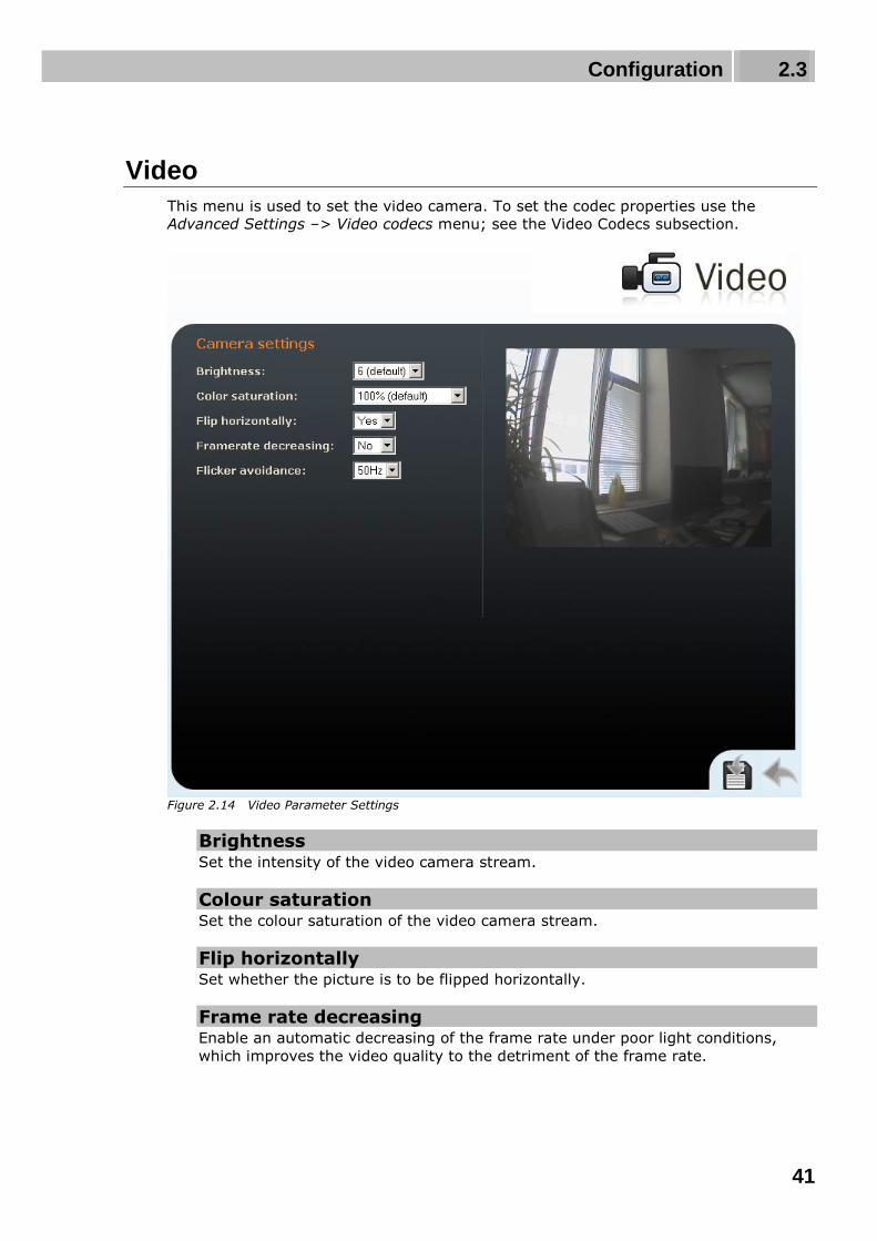
Video
This menu is used to set the video camera. To set the codec properties use the
Advanced Settings –> Video codecs menu; see the Video Codecs subsection.
Figure 2.14 Video Parameter Settings
Brightness Set the intensity of the video camera stream.
Colour saturation Set the colour saturation of the video camera stream.
Flip horizontally Set whether the picture is to be flipped horizontally.
Frame rate decreasing Enable an automatic decreasing of the frame rate under poor light conditions,
which improves the video quality to the detriment of the frame rate.

Configuration 2.3
42
Flicker avoidance Here you can eliminate flicker caused by artificial sources of light such as fluorescent
lamps. The flicker frequency depends on the light source power supply frequency.

Configuration 2.3
43
Audio Codecs
This tag is used for configuration of priorities of the use of audio codecs.
Figure 2.15 Audio Codec Settings
Preferred Audio Codecs
Set the audio codecs for 2N® Helios IP telephone call set-ups. Select G.711 (PCMA or
PCMU), L16, or G.729. Audio codec priorities are determined by the sequence: the
first codec in the sequence has the highest priority. Codec G.729 is supported by
selected 2N® Helios IP models only (refer to the Model Overview subsection).

Configuration 2.3
44
Transmission Quality Settings
Jitter compensation Set the buffer length to compensate jitter caused by variable delays between
incoming RTP packets. A longer buffer mans a better transmission quality yet a
higher transmission delay.
QoS DSCP for audio Set the priority of the audio transmitting packets in the network. The value is
copied into the ToS (Type of Service) field in the IP packet header.
Caution
Wrong settings may deteriorate the transfer quality. Do not change this
parameter if you are not sure. The change in transfer quality will show
only in case the network components support this service.
DTMF Receiving and Sending
Defines how DTMF signalling should be received and sent. Check the opponent‘s
parameters for correct settings.
1. Receive as audio / Send as tones – transmits the DTMF signals in the audio
channel. This setting is unsuitable for cases where the audio channel is
comprised using high-compression codecs such as GSM codecs.
2. Receive as RTP / Send as RTP – transmits DTMF signalling as special RTP
packets according to the RFC2833 recommendation.
3. Receive as SIP INFO / Send as SIP INFO – transmits DTMF signalling using
the SIP INFO packets as recommended in RFC2976.
To send DTMF signalling during a call use the 0 to 9, * and # keys. You can
also disable this function, enable for outgoing calls only, or enable for
incoming and outgoing calls by setting the Send during call parameter.

Configuration 2.3
45
Video Codecs
2N® Helios IP supports video codec H.263, H.263+ or H.264. You can set their
parameters in such a manner that the video transmitted conforms to the needs of the
opponent.
Figure 2.16 Video Codec Settings
Preferred Video Codecs
Set the priority of video codecs for call set-ups.
Video Codec Settings
Video resolution Set the picture formats of the video transmitted. The resolution values range from
QCIF (176x144) to VGA (640×480).
Frame rate Set the frame rate for frames to be sent by 2N® Helios IP to the VoIP network.
Configuration 2.3
46
Video bit rate Set the transmission rate for video transmission from 2N® Helios IP. The lower the
bit rate the greater picture compression is necessary. This results in a lower
picture quality on the receiving end. A high bit rate does not have to mean
significant improvement of transmission as a whole because the network may get
overloaded, resulting in a greater packet loss rate or delay.
Video packet size Set how large the video transmitting packet should be.
Quality Settings
QoS DSCP for video Set the priority of the video transmitting packets in the network. The value is
copied into the ToS (Type of Service) field in the IP packet header.
Caution
Wrong settings may deteriorate the transfer quality. Do not change this
parameter if you are not sure. The change in the transfer quality will show
only in case the network components support this service.
Advanced RTP Settings
RTP payload type Set the Media Format value of the Media attribute (a) in the SPD part of the
INVITE message. Some SIP proxies require this value for a successful video call
set-up. If 0 is selected, the given RTP payload type is not used. It is necessary to
disable one RTP payload type in some SIP proxies, e.g. the Cisco Call Manager.
Caution
Wrong settings may result in a loss of network compatibility. Do not
change this parameter if you are not sure. Losing network compatibility
may cause video transmission errors.
Polycom phone compatibility Set compatibility of SDP messages with some Polycom and Cisco phones. With
this mode on, 2N® Helios IP does not include the sendonly flag in the codec
specification for video streams.

Configuration 2.3
47
Streaming
This function is available to 2N® Helios IP Part Nos. 9137131(CK)E, 9137161(CK)E and
9137111(CK)E with a valid licence key only, Part No. 9137901.
This menu allows the user to enable audio and video streaming into your LAN without
affecting the other functions of 2N® Helios IP. This function is supported by selected
2N® Helios IP models only; refer to the Model Overview subsection. This function may
be used for security purposes. An RTSP supporting receiver is required for acceptance
of audio and video streaming. For this purpose, it is possible to download the VLC
Media player software free of charge. For the VLC media player configuration see
below.
Figure 2.17 Video Streaming Setting
RTSP Server
RTP server Enable and disable audio and video streaming.
Allow IP address Specify the allowed IP address of the stream-receiving user. If the value is not
entered, you can require the stream from any IP address.

Configuration 2.3
48
Enable audio stream Set whether the audio channel is part of the stream transmitted.
Enable video stream Set whether the video channel is part of the stream transmitted.
Enable UDP unicast Enable the RTP/UDP audio and video stream data transmission mode. With this
mode disabled, the audio a video stream data are transmitted by the
RTP/RTSP/TCP only.
Quality Settings
QoS DSCP for video Set the priority of the video transmitting packages in the network. The value is a
decimal number and defines individual bits in the ToS (Type of Service) field in the
IP packet header (bits 8–16).
Caution
Wrong settings may deteriorate the transfer quality. Do not change this
parameter if you are not sure. The change in transfer quality will show
only in case the network components support this service.
Video Codec Settings
Video codec Set one of the following codec modes for video streaming: H.264/MPEG4-AVC or
MPEG4 Part2.
Video resolution Set the individual picture formats for the video transmitted. The resolution values
range from QCIF (176x144) to VGA (640×480).
Frame rate Set the frame rate for frames to be transmitted.
Video bit rate Set the bit rate for video transmission. The parameter affects the compression
ratio and thus the video transmission quality.
Video packet size Set the size limits for the video transmitting RTP packet.
VLC Set-Up for Streaming Video from 2N® Helios IP
1. Install the VLC Media player application (version 0.9.4 in this manual).
2. After installation and start, the window will be displayed as shown in the
figure below.

Configuration 2.3
49
Figure 2.18 VLC Media Player Main Window
3. In the main menu select the source for playing the video, Media->Open
Network.
Figure 2.19 Open Network Connection
4. In the network card select the RTSP protocol and insert the IP address of the
2N® Helios IP device that is sending the video streaming (192.168.3.175 in this
case).
Figure 2.20 RTSP Stream IP Address Setting

Configuration 2.3
50
5. After the OK button is pushed, the video player window will appear.
Figure 2.21 Streaming Video Receiving
6. Push the STOP button to stop receiving the video signal.
7. Open a window of the playlist, Playlist –> Show playlist.
Figure 2.22 Show Playlist
8. The playlist window will display the list of played records, in this case the
RTSP stream from 2N® Helios IP (IP address 192.168.3.175).
Figure 2.23 Playlist Window
9. Save the playlist using the Playlist –> Save playlist to file... menu.

Configuration 2.3
51
Figure 2.24 Save Playlist
10. From now on, whenever opened, the playlist will immediately display video
streaming from the selected 2N® Helios IP device.
Figure 2.25 Streaming Video Receiving

Configuration 2.3
52
JPEG Video Setting
Anonymous access You can download a JPEG video from any IP address without authentication.
Otherwise, the video is only accessible after login or during a call if the Call
activation is enabled.
Call activation Set whether the JPEG video is available to the terminal upon the call beginning.
The function must be supported by the terminal (Snom 820/870, e.g.).
Frame rate Set the transmission rate to be offered to the end terminal.
JPEG quality Set the JPEG image quality. The recommended value is 85. The parameter affects
the image size and quality.
JPEG Video Use
The JPEG video can be used for any application that is capable of downloading
JPEG images from 2N® Helios IP web interface.
To load an image from a camera enter any of the links below in your web
browser:
http://helios_ip_address/enu/camera160x120.jpg
http://helios_ip_address/enu/camera320x240.jpg
http://helios_ip_address/enu/camera352x272.jpg
http://helios_ip_address/enu/camera352x288.jpg
http://helios_ip_address/enu/camera640x480.jpg
Be sure to enable the Anonymous access to the JPEG video (see above) for
this function.
You can assign displaying JPEG images to a Snom 820/870 terminal button.
To do this, set the Action URL function and enter one of the commands below
as the parameter:
Chyba! Odkaz není platný. or
http://helios_ip_address/enu/snom870-video.xml.

Configuration 2.3
53
Auto Update
2N® Helios IP allows both for manual and automatic updates of configuration and
firmware. The automatic update is done through a TFTP server. This function is
supported by selected 2N® Helios IP models only; refer to the Model Overview
subsection.
Figure 2.26 Firmware Update
Automatic Update
TFTP server address The IP address of the TFTP server where the firmware and configuration are
located that are to be automatically uploaded to 2N® Helios IP.
Update firmware Enable/disable automatic firmware downloading from the TFTP server.
Update time Set a period for automatic firmware downloading attempts from the TFTP server.
2N® Helios IP periodically (at a predefined time once a day) checks the TFTP
Configuration 2.3
54
server for a later firmware version. Having found one, 2N® Helios IP updates the
firmware and restarts automatically. With this parameter you can choose the most
convenient time of a day for updating (when 2N® Helios IP is not very busy).
File prefix Specify the TFTP firmware directory path or file prefix. 2N® Helios IP expects the
firmware file to be named Xiphelios_app.bin, where X is the prefix specified in this
parameter.
Update configuration Enable or disable automatic configuration downloading from the TFTP server.
Update period Set the time interval after which 2N® Helios IP gets connected to the TFTP server
for configuration file downloading.
File prefix Specify the TFTP configuration directory path or file prefix. 2N® Helios IP expects
the configuration file to be named Xiphelios_config.ini, where X is the prefix
specified in this parameter.
Update display data Enable/disable automatic display data/program updating from the TFTP server.
The display data are updated in the same time intervals together with the
configuration file.
File prefix Specify the TFTP display data directory path or file prefix. 2N® Helios IP expects
the configuration file to be named Xiphelios_disp.bin, where X is the prefix
specified in this parameter.

Configuration 2.3
55
Display
The 9137160KDE and 9137160CKDE 2N® Helios IP models are equipped with a colour
TFT display, which shows variable information such as digital name tags, telephone
directories, 2N® Helios IP statuses and/or user-defined images. You can set the basic
display parameters in this menu. For the display data uploading to 2N® Helios IP refer
to the Display Program.
Figure 2.27 Display

Configuration 2.3
56
Display Settings
Display enable Enable or disable the display use.
Maximum idle timeout (ads) Set the maximum display idle time (i.e. when the user does not control the device
using the buttons or numeric keypad), after which the advertisement or user-
defined image displaying mode is switched on automatically.
Maximum idle timeout (name tags) Set the maximum display idle time (i.e. when the user does not control the device
using the buttons or numeric keypad), after which the structured telephone
directory mode is switched into the name tag displaying mode.
Search mode Set the mode of searching users in the telephone directory displayed. Either use
the initial name characters (prefixes) or every occurrence of the set characters in
the name (any occurrence).

Configuration 2.3
57
System Log
This menu is used for configuration of system and log message sending. This service is
useful for solving 2N® Helios IP errors if any and contacting the 2N TELEKOMUNIKACE
a.s. Technical Support. Normally, it is not necessary to configure this menu. To receive
syslog messages, a syslog server has to be installed in your PC.
Figure 2.28 System Log
Logging enable Enable or disable sending of system and log reports and storing them on the
syslog server.
Trace level Set the level of detail of the reports.
Syslog server The IP address of the server on which the system log application is running.

Configuration 2.3
58
2N® Helios IP can, in case the called user is unavailable, send an e-mail message
including basic information on the missed call. If 2N® Helios IP is equipped with a
camera, a preset count of pictures on the call course can be sent. This function is
supported by selected 2N® Helios IP models only; refer to the Model Overview
subsection.
Figure 2.29 E-Mail
SMTP Server Settings
Service enabled Enable/disable e-mail sending from 2N® Helios IP.

Configuration 2.3
59
Server name Set the server address to which e-mails shall be sent.
Server port Set the SMTP server port. The default value is 25. Modifications are possible for
other values than the default one.
Login Enter the user name for SMTP login. If authorisation is required, this field must
include a valid name. If not, this field may be blank.
Password Enter the password for SMTP server login authorisation.
E-Mail Settings
Sender’s e-mail Enter the sender’s e-mail address to be included in the messages sent by
2N® Helios IP.
Default e-mail In the case of a missed call, 2N® Helios IP sends a message to the user e-mail
address included in the telephone directory. If the telephone directory field is
blank, the message is sent to the default address included here. If this field is
blank too, no e-mail is sent.
Deliver in Set how long 2N® Helios IP should try to deliver an e-mail to an inaccessible SMTP
server.
E-Mail Content Settings
Attach pictures Set whether the 2N® Helios IP camera pictures shall be attached to the e-mail
message.
Number of pictures Set the count of pictures to be taken during ringing and sent enclosed to the
missed call message.
Picture resolution Set resolution for the pictures to be sent.
Subject Specify the subject of the e-mail message to be sent.
Body Enter the content of the e-mail message to be sent using any HTML formatting
tags. You can also insert special pre-defined symbols for certain data, such as

Configuration 2.3
60
user name, date, time, identification and/or called number. These symbols are
replaced with real values before sending. Refer to the table below:
$User$ Called user name
$DateTime$ Current date and time
$DialNumber$ Called number
$HeliosId$ 2N® Helios IP identifier

Configuration 2.3
61
Multicast
2N® Helios IP is able to receive the LAN-transmitted audio stream on the set multicast
IP address and port and play it on the background. The audio stream must be in the
RTP / UDP format and use codec G.711 (PCMU). The received audio stream is played
even during an active call where the two sound sources are mixed together.
Figure 2.30 Multicast
Multicast Receiver Settings
Multicast enabled Enable/disable receiving the audio stream on multicast address.
Multicast address Multicast IP address from which 2N® Helios IP receives the audio stream.

Configuration 2.3
62
Port Port via which the audio stream is received.
Volume Volume of the audio stream received.

Configuration 2.3
63
Miscellaneous
Here set the additional parameters of 2N® Helios IP that were not included in the
above-described menus.
Figure 2.31 Miscellaneous Settings
Outgoing Calls
Ring time limit Set the call set-up and ringing time limits for outgoing calls. If the calls are routed
through the GSM gateways of Part Nos. 505004, 505214 or 505612 to the GSM
network, it is advisable to set a time value longer than 20 s.
Call time limit Set the maximum call duration. When the call end is approaching, 2N® Helios IP
starts generating tones signalling the end of the call. The call will automatically be
terminated 10s after this signal. To prolong the call, send a DTMF code (push #,
e.g.) on your phone.
Configuration 2.3
64
Dial cycles limit Set the maximum count of telephone directory searching attempts. The function is
useful whenever the substitute is defined and in the case of deadlock.
Incoming Calls
Automatic answer Defines how 2N® Helios IP should behave when a call is coming. If the Automatic
answer is disabled, 2N® Helios IP signals an incoming calls by ringing and the
external subscriber can answer or reject the call by pushing * or # respectively. If
the Automatic answer is enabled, 2N® Helios IP receives the call automatically and
processes as selected in the Activation mode and Activation code parameters.
Activation mode If the Automatic answer is enabled, incoming calls are received automatically by
2N® Helios IP. 2N® Helios IP enables you to receive up to 3 incoming calls at the
same time. You can control 2N® Helios IP through incoming calls using tone
dialling from your telephone keypad (activate or deactivate users or profiles,
e.g.). A single incoming call may only be connected with the 2N® Helios IP
microphone, loudspeaker and camera. Use the Activation mode parameter to
define whether the incoming call should be connected automatically, or the
activation code should be required for connection (see below).
Activation code Set the activation code necessary for interconnecting the incoming call audio and
video if the Automatic answer is enabled and the Activation code is set to Manual.
Beep on connect Use this parameter to enable/disable 2N® Helios IP connection signalling by a beep
during an incoming call.
Keyboard Settings
Hang up by # button Enable call termination with the # key.
Same button function Assign a function to the call-establishing quick dialling button when re-pushed.
None – re-pushing the quick dialling button does not affect the set up or
active call.
Hang-up – re-pushing the quick dialling button ends the set-up or active call.
Dial next – re-pushing the quick dialling button allows you to skip an attempt
to set up a call and proceed to the next telephone
number in the directory for another set-up.
Flash – re-pushing the quick dialling button sends the FLASH signal into the
active call.

Configuration 2.3
65
Quick dialling using digits Enable user calling from the telephone directory by dialling the user number (two
or three digits) and confirmation with *.
Floor & Apartment dialling Enable special calling to numbers included in the telephone directory by entering a
floor number on the numerical keypad and pushing a quick dialling button.
Buttons 1 – 6 represent apartments on the floor (A through F). The following
floors and apartments are assigned to telephone directory positions: 01A – 1, 01B
– 2, 01C – 3, 01D – 4, 01E – 5, 01F – 6, 02A – 7, 02B – 8 etc. until 99F – 594.
Keystroke timeout Set the delay between two digits when entering a code or telephone number using
the 2N® Helios IP keypad.
Enable telephone mode Enable to set up calls directly to the telephone numbers entered from the
2N® Helios IP numeric keypad using the *telephone_number* key sequence.
Dial digits limit Define the maximum number of digits of a telephone number in the Telephone
mode. When the defined count is reached, the telephone number is dialled
automatically without the need to push * subsequently.
Legacy switch code Set whether the first code in the switch 1 and switch 2 list may be entered from a
VoIP phone valid without an * confirmation.
Other Settings
Backlight level Set the level of the keypad backlight.
Red LED control
Set the card reader input that activates the red LED located under the
2N® Helios IP Vario name plates. The red LED can indicate the secured /
unsecured state, for example. This function is available in 2N® Helios IP Vario
models without display, Part. Nos. 91371…U.
DHCP on/off by buttons Set whether a quick dialling button combination may switch to obtaining the IP
address from the DHCP server upon the 2N® Helios IP restart as described in the
Device configuration subsection of 2N® Helios IP Installation Manual.
Enable switch control by HTTP Enable switch control by HTTP requests sent by 2N® Helios IP. Select ON, OFF or
change over upon the following HTTP (GET) request:
http://helios_ip_address/enu/lockstate.xml.p?lockXstate=Y, where X is the switch
number (1-4) and Y is 0 for switch off, 1 for switch on and 2 for change over.

Configuration 2.3
66
RFID Card Reader
2N® Helios IP (Part Nos. 91371…U) can be equipped with an internal multifunction
module including an RFID card reader (Part No. 9137430E). This module enhances the
2N® Helios IP functions with an EM41XX RFID card reader, two relays for external load
switching, two logical inputs and RS-485 and Wiegand interfaces. The current
2N® Helios IP software version, however, supports the card reader and relays only.
RFID Card Reader Function
2N® Helios IP enables you to assign one RFID card to each user in the telephone
directory. Set the user card identification code in the ID card parameter in the
Telephone directory menu. Refer to the Telephone directory subs. for details. When
a valid card is applied, the switch assigned to the card reader gets activated. Assign
the switch in the card reader module setting menu (in RFID Card Reader - Module
Settings).
We recommend you to use an external RFID card reader (Part No. 9137420E), which
can be connected to your PC (refer to the Configuration with External RFID Card
Reader subs.) and facilitate your setting of the user card identification codes.
Use of Plus and Minus Cards
The so-called plus and minus cards help you add and remove cards easily without
using the 2N® Helios IP configuration menu. The function works as follows:
Select two RFID cards marking them with + and -. Use the plus card to add items to
and the minus card to remove items from the 2N® Helios IP list of valid cards. Enter
the identification codes of these two cards into the Plus card ID and Minus card ID
fields respectively in the card reader module setting menu.
To add a card to the list of valid cards, apply the plus card to 2N® Helios and then, no
later than 3 seconds, the card to be added. The card will be added to the first free line
in the list of available valid cards. If there is no more free space in the list, the card
will not be installed. Installation or rejection will be signalled acoustically.
To remove a card from the list of valid cards, apply the minus card to 2N® Helios IP
and then, no later than 3 seconds, the card to be removed.
You can manage up to 10 cards in this way. Use the Installed cards menu (RFID Card
Reader - Installed Cards) to modify the list of available cards.
Keep the plus and minus cards on a safe place to avoid misuse.
RFID Card ID
An identification code is a unique RFID card number consisting of two asterisk-
separated sections. The first section specifies the ID type (format) and the other
provides the ID number itself. The current software version supports the following two
formats:
0*XXXXXXX ‘0’ is the internal 2N® Helios IP format.

Configuration 2.3
67
1*XXXXXXX ‘1’ is the external USB RFID card reader format (Part No.
9137420E).
Configuration with External RFID Card Reader
To facilitate entering card ID codes into 2N® Helios IP, we recommend you to order an
external RFID card reader (Part No. 9137420E), which can be connected to your PC
via a USB interface. Enter the card ID into 2N® Helios IP using the web interface as
follows:
Enter 1* (ID type) into the card ID field and leave the cursor behind the asterisk. The
card reader behaves as a keyboard connected to your PC and, when the card is
applied, writes the card ID code into the rest of the field automatically.
Configuration without External RFID Card Reader
No external card reader is needed in some simple 2N® Helios IP installations for few
users. To add an ID code, just apply the new card to 2N® Helios IP and copy its ID
displayed in the Access Log (RFID Card Reader – Access Log) into the respective field.
Make sure that you have installed the right card.
Use of RFID Card Reader Module Relay
The card reader module is equipped with two relays for various purposes such as
switching of other electronic locks, lighting, etc. Set these relays to Reader switch
#1 or Reader switch #2 in the Switches section of the Switch setting menu.

Configuration 2.3
68
RFID Card Reader – Module Settings
See below for the basic card reader settings.
Figure 2.32 Card Reader – Module Settings
Card Reader Settings
Card reader enabled Enable or disable the card reader function temporarily.
Accepted HID cards
Select the HID card standard to be accepted.

Configuration 2.3
69
Associated switch Set the switch to be activated by a valid card.
Plus card ID Enter the ID of the plus card to be used for adding items into the list of valid cards
(RFID Card Reader - Installed Cards). If you leave this parameter blank, the
plus/minus card function cannot be applied.
Minus card ID Enter the ID of the minus card to be used for removing items from the list of valid
cards (RFID Card Reader - Installed Cards). If you leave this parameter blank, the
plus/minus card function cannot be applied.
Wiegand Interface If equipped with a RFID card reader, 2N® Helios IP offers the Wiegand interface
for connection of third party devices: an additional card reader, fingerprint reader
or access control/security system, for example.
Interface mode Set the information transmission direction for the Wiegand interface of the
internal card reader. In the Input mode, 2N® Helios IP receives data sent along
the bus and compares them with the internal database of card identifiers. This
mode is used, e.g., for a biometric data reader. In the Output mode,
2N® Helios IP sends identifiers of the read cards to the interface. This mode is
used, e.g., for connection of an access control system.
Change facility code Enable a mode in which the facility code in the card identifier sent by the Wiegand
interface will be replaced with the code specified in the Facility code parameter.
Facility code Facility code. Refer to the Change facility code parameter above.

Configuration 2.3
70
RFID Card Reader – Installed Cards
The table includes the list of cards installed in 2N® Helios IP using the plus and minus
cards. The valid cards can be installed manually too.
Figure 2.33 Card Reader – Installed Cards
Installed Cards
Card ID Enter the RFID card ID.
Profile Assign a time profile to each card to control its validity. Refer to the Profiles subs.
for details.
Description Fill in any information concerning the card, e.g. the card owner. 2N® Helios IP
does not use this field.

Configuration 2.3
71
RFID Card Reader – Access Log
This table provides information on the last ten cards applied to the 2N® Helios IP card
reader.
Figure 2.34 Card Reader – Access Log
Recently Detected Cards
Time Card detection date and time.
Card ID Card ID code.
Description Additional information on the card applied, i.e. valid/invalid, assigned user, etc.

Configuration 2.3
72
Tools
This menu helps you set the 2N® Helios IP date and time manually and reboot the device.
Figure 2.35 Tools
Local Date and Time Setting
Used for date and time setting in case the NTP synchronisation is disabled (see the
Date and Time subsection). Push the button to synchronise the 2N® Helios IP
time with your PC time.
Reboot device
Used for device restarting in case of changes of some configuration parameters,
namely network settings, administration web interface settings and some SIP
configuration parameters.
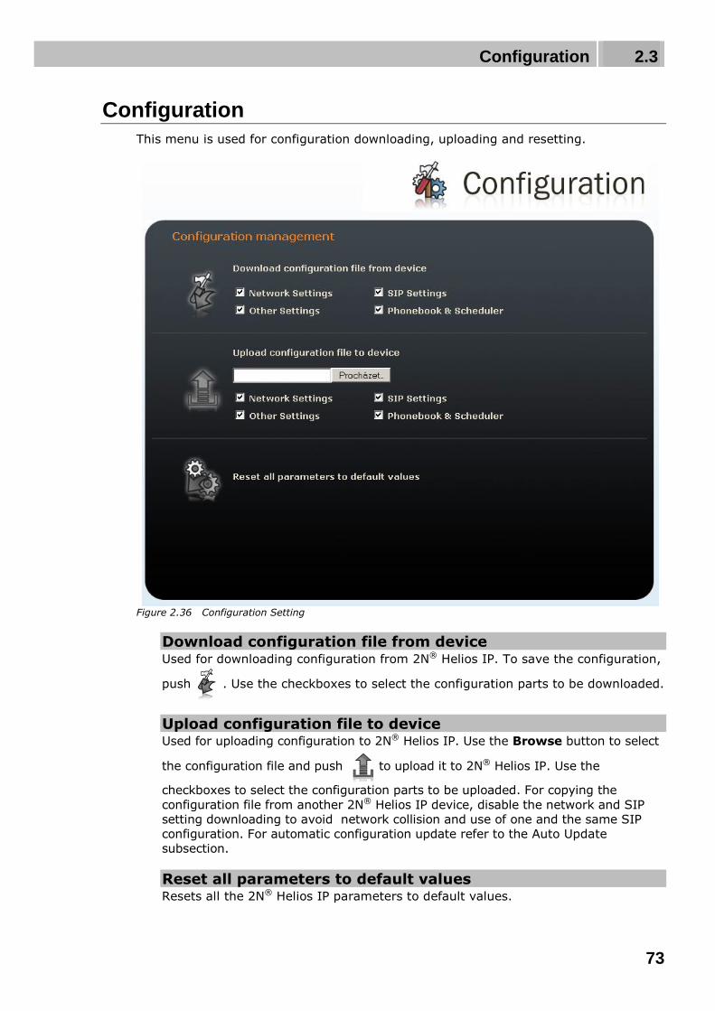
Configuration 2.3
73
Configuration
This menu is used for configuration downloading, uploading and resetting.
Figure 2.36 Configuration Setting
Download configuration file from device Used for downloading configuration from 2N® Helios IP. To save the configuration,
push . Use the checkboxes to select the configuration parts to be downloaded.
Upload configuration file to device Used for uploading configuration to 2N® Helios IP. Use the Browse button to select
the configuration file and push to upload it to 2N® Helios IP. Use the
checkboxes to select the configuration parts to be uploaded. For copying the
configuration file from another 2N® Helios IP device, disable the network and SIP
setting downloading to avoid network collision and use of one and the same SIP
configuration. For automatic configuration update refer to the Auto Update
subsection.
Reset all parameters to default values Resets all the 2N® Helios IP parameters to default values.

Configuration 2.3
74
Caution
This selection does not apply to the network settings to avoid network
collision and disabling the option to configure using the administration web
server.

Configuration 2.3
75
Display Program
This menu is used for display program uploading. The display program is prepared
using the configuration tool available on the attached CD. For display settings refer to
the Display subsection.
Figure 2.37 Display Program Uploading
Display program upload Used for uploading the display program to 2N® Helios IP. Use the Browse button
to select the configuration file and push to upload it to 2N® Helios IP. If no
file is selected, the current display program is removed from the memory when
this button is pressed.

Configuration 2.3
76
Firmware
This menu is used for manual firmware updating.
Figure 2.38 Firmware
Manual Firmware Update
Used for manual firmware updating using the configuration web interface. Use
the Browse button to select the new firmware file and push to upload it
to 2N® Helios IP. For automatic update refer to the Auto Update subsection.

Configuration 2.3
77
User Sounds
This menu helps create customised signalling of 2N® Helios IP states by replacing the
default tone signalling with user sound files.
Figure 2.39 User Sounds
User Sound Upload
Used for handling user sound files within 2N® Helios IP. Push the Browse button to
select a sound file and then push to upload the file into 2N® Helios IP. The user
sound format is an 8bit or 16bit .WAV file with 8kHz sampling frequency. Push to
remove the file uploaded. Push to play and verify the recorded sound on your PC.
The following user sounds can be used:

Configuration 2.3
78
Hang-up by remote party – here replace the disconnect tone signalling that
the called station has hung up.
Busy tone – replace the standard busy tone.
Invalid input – replace the invalid switch code sound.
Invalid position – replace the speed dial button sound signalling a non-
programmed telephone directory position.
Switch activation – replace the switch activation sound.
Ringing – replace the standard incoming ringing tone when the Automatic
call answering function is off, refer to the Miscellaneous
subsection.

Configuration 2.3
79
Certificates
The Certificates menu helps you set certificates and private keys for the 2N® Helios IP
functions that use the TLS protocol for communication with the counterparty. The
purpose of the certificates is to verify the authorisation of devices to communicate.
Certificates
Trusted certificates (CA certificates) Set the certificates from certification authorities to be used for verification of the
2N® Helios IP counterparty’s certificate. Specify up to three sets of certificates
marked (1), (2) and (3). 2N® Helios IP accepts the following certificate formats:
DER (ASN1) and PEM.
User certificates and private keys Set the certificates and private keys to be used for verification of the
2N® Helios IP authorisation to communicate with the counterparty. Specify up to

Configuration 2.3
80
three sets of public certificates and private keys marked (1), (2) and (3).
2N® Helios IP accepts the following certificate formats: DER (ASN1) and PEM.
The three sets of certificates help you set different certificates for different network
protocols for successful 2N® Helios IP communication. Select the certificate set(s) for
the following functions:
HTTPS for secure access to the 2N® Helios IP configuration requires a user
certificate and private key. Assign the certificate in the web server setting
menu; refer to the Administration Web Server subsection.
SMTP for e-mail transmission requires a user certificate, private key and,
optionally, a certification authority certificate. Assign the certificates in the
SMTP client setting menu; refer to the E-Mail subsection.
802.1x EAP-TLS requires a user certificate, private key and, optionally, a
certification authority certificate. Assign the certificates in the network setting
menu; refer to the Network subsection.

Configuration 2.3
81
Network Trace
This menu helps capture incoming and outgoing packets on the 2N® Helios IP network
interface. The file with the captured data can be downloaded and analysed, using,
e.g., Wireshark (www.wireshark.org). Push the Start button to launch capturing and
the Stop button to terminate capturing.
The captured packets are stored in the ring buffer of the size of 4MB. Whenever the
buffer is filled up, the oldest packets are deleted automatically. You are recommended
to reduce the video stream transmission speed for packet capturing below 512kbps.
Figure 2.40 Network Trace

Configuration 2.3
82
Licence
This menu is used for entering licence keys, Part Nos. 9137901 and 9137902. Licence
keys upgrade the 2N® Helios IP functionality (see the Model Overview subsection).
Contact your local distributor for the licence key to your 2N® Helios IP.
Figure 2.41 Licence
Licence
Licence type Displays the type of licence currently saved in 2N® Helios IP. The available
features of your licence are displayed in the Available features subsection.
Licence expiry 2N® Helios IP models of Part Nos. 9137131(CK), 9137161(CK) and 9137111(CK)
are available with the Basic licence. You can activate the Professional licence for a
limited operating time (800 hours) to test all the system capacities. Click on the
Start evaluation mode for 800 hours to enable the Professional licence. The

Configuration 2.3
83
licence will expire in 800 hours and can only be run once. Your Basic functions will
be restored after its expiry. Note: Each restart shortens the temporary licence
validity by one hour.
Licence key Enter the licence key received from your distributor in this field.
Available Features
Provides details on the 2N® Helios IP features following from the applicable licence.

Configuration 2.3
84
Signalling of Operational Statuses
2N® Helios IP generates sounds to signal operational mode switching and changes.
There are different types of acoustic signals for each type of status change. The list of
operational status signals is included in Table 3.1.
Tones Meaning
User activated
after entering the user activation code. The activation code is
used for activating a user (a telephone directory position). For
activation code setting refer to the Telephone Directory
subsection
User deactivated
after entering the user deactivation code. The deactivation code is
used for deactivating a user (a telephone directory position). A
deactivated user may not be called but the call may, if necessary,
be forwarded to a substitute if defined. For deactivation code
setting refer to the Telephone Directory subsection.
Profile activated
used for profile activation. It can be used, for example, to enable
alerting of a user group of users in an office. Refer to the Profiles
subsection for activation code setting.
Profile deactivated
used for profile deactivation. It can be used, for example, to
disable alerting a user group in an office and forward the call to a
selected telephone number, or the reception or a cellular phone.
Refer to the Profiles subsection for deactivation code setting.
Call prolongation confirmation signalling
a maximum call duration is set for blocking protection reasons,
see the Miscellaneous subsection.
Internal application launched
after turning on or restarting of 2N® Helios IP, the internal
application of 2N® Helios IP is launched. A successful launch is
signalled by this tone combination.
Connected to LAN, IP address received
after the launch of the internal application 2N® Helios IP logs into
the LAN. A successful login is signalled by this tone combination.
Disconnected from LAN, IP address lost
whenever the UTP cable is disconnected from 2N® Helios IP, this
status is signalled by this tone combination.
Invalid telephone number or invalid switch code
you can dial an extension telephone number or enter the door-
opening code using the keypad. An invalid code is signalled by
this tone sequence.

Configuration 2.3
85
Switching to default network parameters
after power up, a 30-second timeout is set for entering the
resetting code. For switching to default network parameters refer
to the Device configuration subsection of 2N® Helios IP
Installation Manual.
Call end signalling
a time limit can be set after which your call will be terminated. To
prolong a call, push a VoIP telephone key. The time limit is set
due to protection against call blocking.
Connected call for VoIP phone-to-2N® Helios IP calling
a short tone is played to signal call connection.
Table 2.2 List of Operational Status Signals

List of Figures 2.4
86
2.4 List of Figures
Figure 2.1 Telephone Directory Navigation Bar .............................................................................. 14
Figure 2.2 2N® Helios IP Network Scanner Installation Wizard ...................................................... 17
Figure 2.3 2N® Helios IP Network Scanner Window....................................................................... 17
Figure 2.4 Language Selection ....................................................................................................... 18
Figure 2.5 Basic Information ........................................................................................................... 19
Figure 2.6 Telephone Directory ...................................................................................................... 21
Figure 2.7 Profile Set-up ................................................................................................................. 24
Figure 2.8 Switch Settings .............................................................................................................. 26
Figure 2.9 Network Parameter Setting ............................................................................................ 29
Figure 2.10 Date and Time Settings ............................................................................................... 32
Figure 2.11 SIP Settings ................................................................................................................. 34
Figure 2.12 Web Server Configuration ........................................................................................... 37
Figure 2.13 Audio Parameter Settings ............................................................................................ 39
Figure 2.14 Video Parameter Settings ............................................................................................ 41
Figure 2.15 Audio Codec Settings .................................................................................................. 43
Figure 2.16 Video Codec Settings .................................................................................................. 45
Figure 2.17 Video Streaming Setting .............................................................................................. 47
Figure 2.18 VLC Media Player Main Window ................................................................................. 49
Figure 2.19 Open Network Connection ........................................................................................... 49
Figure 2.20 RTSP Stream IP Address Setting ................................................................................ 49
Figure 2.21 Streaming Video Receiving ......................................................................................... 50
Figure 2.22 Show Playlist................................................................................................................ 50
Figure 2.23 Playlist Window ............................................................................................................ 50
Figure 2.24 Save Playlist ................................................................................................................ 51
Figure 2.25 Streaming Video Receiving ......................................................................................... 51
Figure 2.26 Firmware Update ......................................................................................................... 53

List of Figures 2.4
87
Figure 2.27 Display ......................................................................................................................... 55
Figure 2.28 System Log .................................................................................................................. 57
Figure 2.29 E-Mail ........................................................................................................................... 58
Figure 2.30 Multicast ....................................................................................................................... 61
Figure 2.31 Miscellaneous Settings ................................................................................................ 63
Figure 2.32 Card Reader – Module Settings .................................................................................. 68
Figure 2.33 Card Reader – Installed Cards .................................................................................... 70
Figure 2.34 Card Reader – Access Log .......................................................................................... 71
Figure 2.35 Tools ............................................................................................................................ 72
Figure 2.36 Configuration Setting ................................................................................................... 73
Figure 2.37 Display Program Uploading ......................................................................................... 75
Figure 2.38 Firmware ...................................................................................................................... 76
Figure 2.39 User Sounds ................................................................................................................ 77
Figure 2.40 Network Trace.............................................................................................................. 81
Figure 2.41 Licence ......................................................................................................................... 82

List of Tables 2.5
88
2.5 List of Tables
Table 2.1 Model Overview ............................................................................................................ 11
Table 2.2 List of Operational Status Signals ................................................................................. 85

2N TELEKOMUNIKACE a.s.
Modřanská 621, 143 01 Prague 4, Czech Republic Tel.: +420 261 301 500, Fax: +420 261 301 599
E-mail: [email protected]
Web: www.2n.cz