manual cx2100-00x4 - beckhoffftp.beckhoff.com/download/document/ipc/embedded-pc/embedded-p… ·...
TRANSCRIPT

Manual
CX2100-00x4
Power supply for CX20xx
1.22017-05-15
Version:Date:


Table of contents
CX2100-00x4 3Version: 1.2
Table of contents1 Foreword .................................................................................................................................................... 5
1.1 Notes on the documentation........................................................................................................... 51.2 Safety instructions .......................................................................................................................... 61.3 Documentation issue status............................................................................................................ 7
2 Product overview....................................................................................................................................... 82.1 Intended use ................................................................................................................................... 82.2 CX2100-00x4 – product overview................................................................................................... 92.3 CX2100-0004 - Technical data ..................................................................................................... 102.4 CX2100-0014 - Technical data ..................................................................................................... 112.5 Display .......................................................................................................................................... 12
2.5.1 Structure of the display .................................................................................................... 122.5.2 Displaying texts ................................................................................................................ 13
2.6 Button ........................................................................................................................................... 232.6.1 Operating principle of the button...................................................................................... 23
2.7 Example Program ......................................................................................................................... 25
3 Transport.................................................................................................................................................. 283.1 Unpacking, installation and transport............................................................................................ 28
4 Mounting and wiring ............................................................................................................................... 294.1 Mechanical installation.................................................................................................................. 29
4.1.1 Dimensions ...................................................................................................................... 294.2 Commissioning ............................................................................................................................. 31
4.2.1 Power supply.................................................................................................................... 314.3 Installation on the mounting rail .................................................................................................... 344.4 Mounting the module lock............................................................................................................. 364.5 Mounting of passive terminals on the CX2100-0xx4 power supply .............................................. 38
5 Error handling and diagnostics ............................................................................................................. 395.1 Diagnostics in the PLC program ................................................................................................... 39
6 Decommissioning.................................................................................................................................... 406.1 Disassembly and disposal ............................................................................................................ 40
7 Appendix .................................................................................................................................................. 427.1 Accessories .................................................................................................................................. 427.2 Certifications ................................................................................................................................. 437.3 Support and Service ..................................................................................................................... 44

Table of contents
CX2100-00x44 Version: 1.2

Foreword
CX2100-00x4 5Version: 1.2
1 Foreword
1.1 Notes on the documentationThis description is only intended for the use of trained specialists in control and automation engineering whoare familiar with the applicable national standards.It is essential that the documentation and the following notes and explanations are followed when installingand commissioning the components. It is the duty of the technical personnel to use the documentation published at the respective time of eachinstallation and commissioning.
The responsible staff must ensure that the application or use of the products described satisfy all therequirements for safety, including all the relevant laws, regulations, guidelines and standards.
Disclaimer
The documentation has been prepared with care. The products described are, however, constantly underdevelopment.We reserve the right to revise and change the documentation at any time and without prior announcement.No claims for the modification of products that have already been supplied may be made on the basis of thedata, diagrams and descriptions in this documentation.
Trademarks
Beckhoff®, TwinCAT®, EtherCAT®, Safety over EtherCAT®, TwinSAFE®, XFC® and XTS® are registeredtrademarks of and licensed by Beckhoff Automation GmbH.Other designations used in this publication may be trademarks whose use by third parties for their ownpurposes could violate the rights of the owners.
Patent Pending
The EtherCAT Technology is covered, including but not limited to the following patent applications andpatents:EP1590927, EP1789857, DE102004044764, DE102007017835with corresponding applications or registrations in various other countries.
The TwinCAT Technology is covered, including but not limited to the following patent applications andpatents:EP0851348, US6167425 with corresponding applications or registrations in various other countries.
EtherCAT® is registered trademark and patented technology, licensed by Beckhoff Automation GmbH,Germany
Copyright
© Beckhoff Automation GmbH & Co. KG, Germany.The reproduction, distribution and utilization of this document as well as the communication of its contents toothers without express authorization are prohibited.Offenders will be held liable for the payment of damages. All rights reserved in the event of the grant of apatent, utility model or design.
Foreword
CX2100-00x46 Version: 1.2
1.2 Safety instructions
Safety regulations
Please note the following safety instructions and explanations!Product-specific safety instructions can be found on following pages or in the areas mounting, wiring,commissioning etc.
Exclusion of liability
All the components are supplied in particular hardware and software configurations appropriate for theapplication. Modifications to hardware or software configurations other than those described in thedocumentation are not permitted, and nullify the liability of Beckhoff Automation GmbH & Co. KG.
Personnel qualification
This description is only intended for trained specialists in control, automation and drive engineering who arefamiliar with the applicable national standards.
Description of symbols
In this documentation the following symbols are used with an accompanying safety instruction or note. Thesafety instructions must be read carefully and followed without fail!
DANGER
Serious risk of injury!Failure to follow the safety instructions associated with this symbol directly endangers thelife and health of persons.
WARNING
Risk of injury!Failure to follow the safety instructions associated with this symbol endangers the life andhealth of persons.
CAUTION
Personal injuries!Failure to follow the safety instructions associated with this symbol can lead to injuries topersons.
Attention
Damage to the environment or devicesFailure to follow the instructions associated with this symbol can lead to damage to the en-vironment or equipment.
Note
Tip or pointerThis symbol indicates information that contributes to better understanding.
Foreword
CX2100-00x4 7Version: 1.2
1.3 Documentation issue statusVersion Modifications0.1 Provisional version (original version)1.0 First version1.1 UL requirements added1.2 Technical data revised
Product overview
CX2100-00x48 Version: 1.2
2 Product overview
2.1 Intended useThe CX20x0 device series is a modular control system designed for DIN rail installation. The system isscalable, so that the required modules can be assembled and installed in the control cabinet or terminal boxas required.
Only switch the PC off after closing the software
Before the Embedded PC is switched off, the software currently running on it should be stopped properly inorder to avoid data loss on the hard disk. Please read the section on “Switching off”.
Switch off all system components and uncouple the Industrial PC from the system if the PC is not used forcontrol purposes, e.g. during a function test. To disconnect first pull the first terminal behind the powersupply unit (optional), then pull the connectors of the fieldbus connections.System components that have been switched off must be secured against being switched on again.
The Embedded PC’s power supply unit must be supplied with 24 VDC.
Attention
Damage to the environment or devicesDo not exchange any parts when under power! The exchange of controller parts when livecan lead to short-circuits or overvoltages. These can damage the controller itself and con-nected peripherals (terminals, monitors, input devices, etc.).
When components are being fitted or removed, the supply voltage must be switched off.
Software knowledge
Attention
System malfunctionsMandatory software knowledge! Every user must be familiar with any of the functions of thesoftware installed on the PC that he can reach.
Product overview
CX2100-00x4 9Version: 1.2
2.2 CX2100-00x4 – product overview
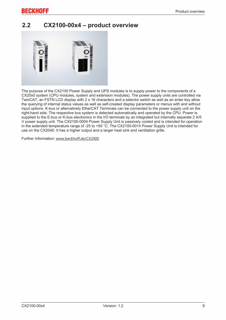
The purpose of the CX2100 Power Supply and UPS modules is to supply power to the components of aCX20x0 system (CPU modules, system and extension modules). The power supply units are controlled viaTwinCAT. an FSTN LCD display with 2 x 16 characters and a selector switch as well as an enter key allowthe querying of internal status values as well as self-created display parameters or menus with and withoutinput options. K-bus or alternatively EtherCAT Terminals can be connected to the power supply unit on theright-hand side. The respective bus system is detected automatically and operated by the CPU. Power issupplied to the E-bus or K-bus electronics in the I/O terminals by an integrated but internally separate 2 A/5V power supply unit. The CX2100-0004 Power Supply Unit is passively cooled and is intended for operationin the extended temperature range of -25 to +50 °C. The CX2100-0014 Power Supply Unit is intended foruse on the CX2040. It has a higher output and a larger heat sink and ventilation grille.
Further Information: www.beckhoff.de/CX2000
Product overview
CX2100-00x410 Version: 1.2
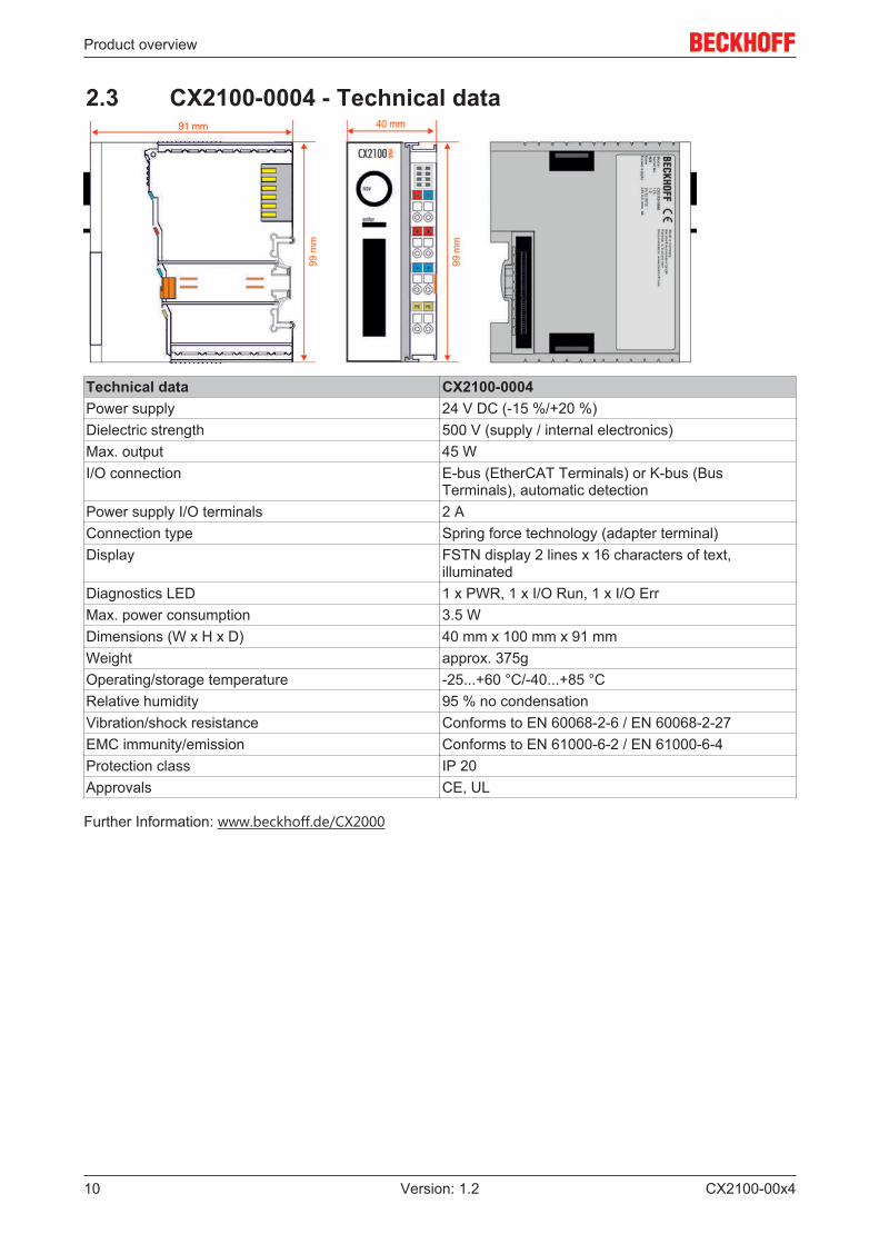
2.3 CX2100-0004 - Technical data
Technical data CX2100-0004Power supply 24 V DC (-15 %/+20 %)Dielectric strength 500 V (supply / internal electronics)Max. output 45 WI/O connection E-bus (EtherCAT Terminals) or K-bus (Bus
Terminals), automatic detectionPower supply I/O terminals 2 AConnection type Spring force technology (adapter terminal)Display FSTN display 2 lines x 16 characters of text,
illuminatedDiagnostics LED 1 x PWR, 1 x I/O Run, 1 x I/O ErrMax. power consumption 3.5 WDimensions (W x H x D) 40 mm x 100 mm x 91 mmWeight approx. 375gOperating/storage temperature -25...+60 °C/-40...+85 °CRelative humidity 95 % no condensationVibration/shock resistance Conforms to EN 60068-2-6 / EN 60068-2-27EMC immunity/emission Conforms to EN 61000-6-2 / EN 61000-6-4Protection class IP 20Approvals CE, UL
Further Information: www.beckhoff.de/CX2000
Product overview
CX2100-00x4 11Version: 1.2
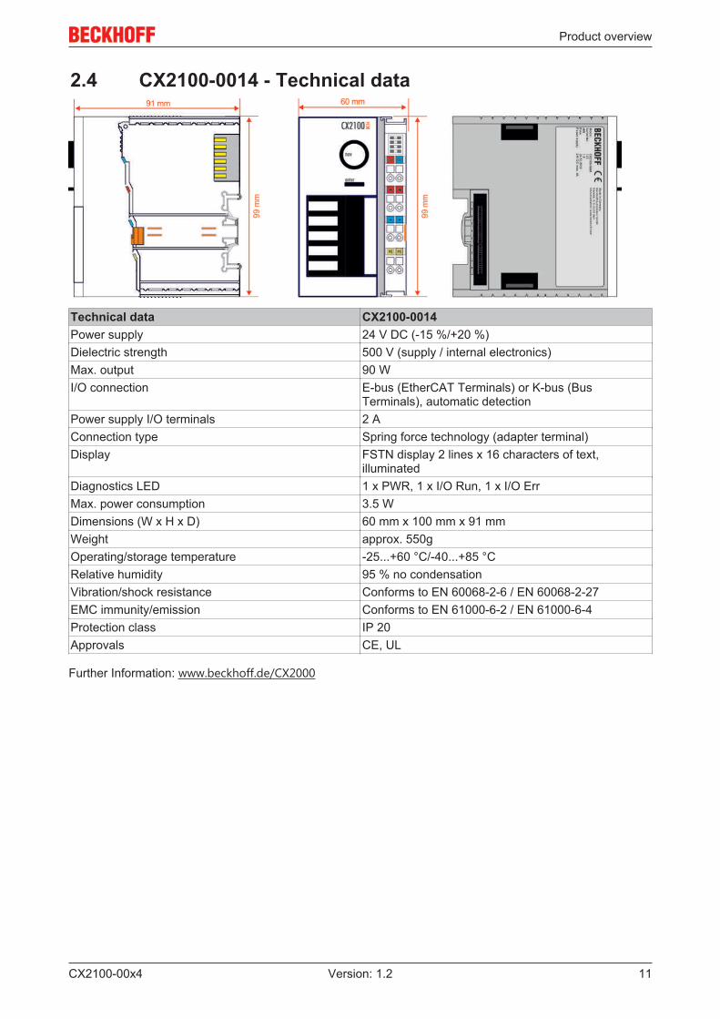
2.4 CX2100-0014 - Technical data
Technical data CX2100-0014Power supply 24 V DC (-15 %/+20 %)Dielectric strength 500 V (supply / internal electronics)Max. output 90 WI/O connection E-bus (EtherCAT Terminals) or K-bus (Bus
Terminals), automatic detectionPower supply I/O terminals 2 AConnection type Spring force technology (adapter terminal)Display FSTN display 2 lines x 16 characters of text,
illuminatedDiagnostics LED 1 x PWR, 1 x I/O Run, 1 x I/O ErrMax. power consumption 3.5 WDimensions (W x H x D) 60 mm x 100 mm x 91 mmWeight approx. 550gOperating/storage temperature -25...+60 °C/-40...+85 °CRelative humidity 95 % no condensationVibration/shock resistance Conforms to EN 60068-2-6 / EN 60068-2-27EMC immunity/emission Conforms to EN 61000-6-2 / EN 61000-6-4Protection class IP 20Approvals CE, UL
Further Information: www.beckhoff.de/CX2000
Product overview
CX2100-00x412 Version: 1.2
2.5 Display
2.5.1 Structure of the display
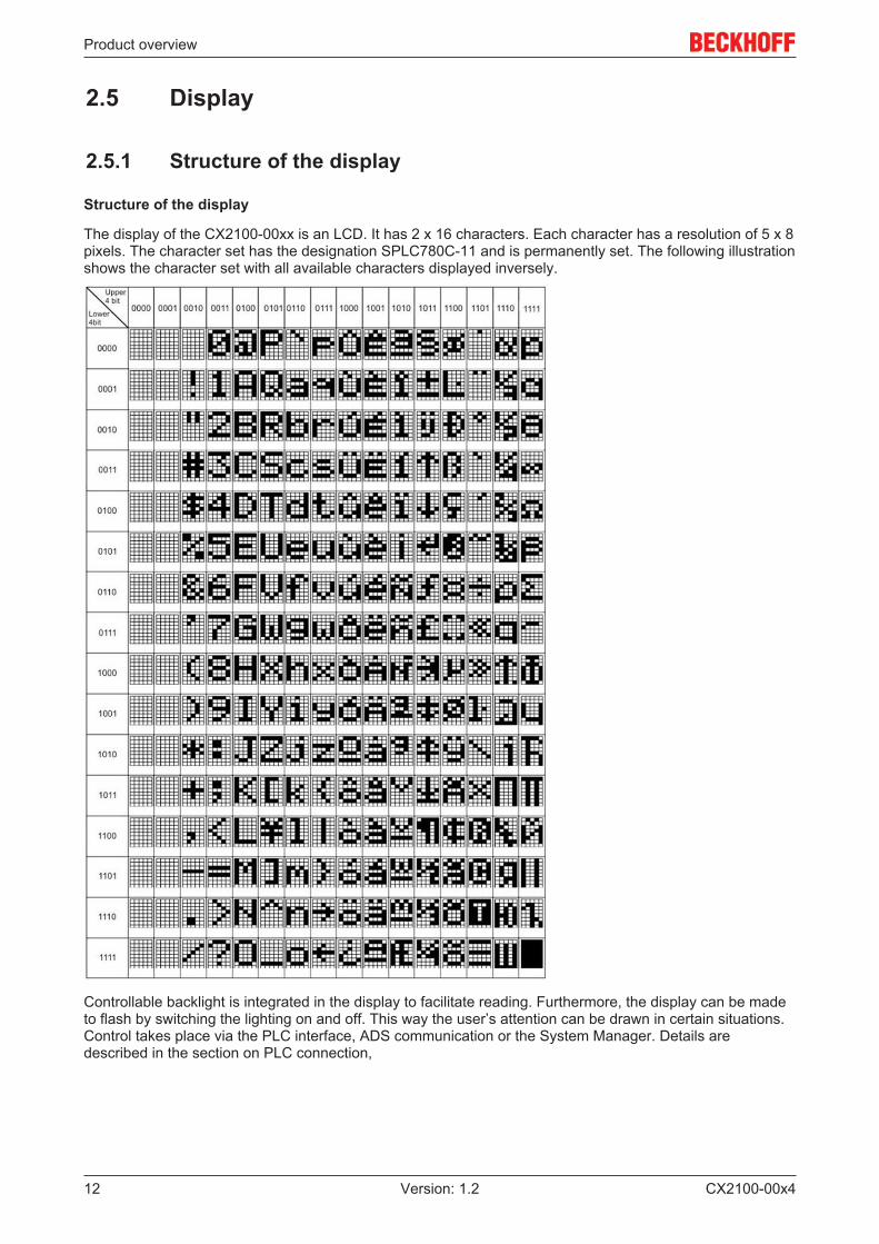
Structure of the display
The display of the CX2100-00xx is an LCD. It has 2 x 16 characters. Each character has a resolution of 5 x 8pixels. The character set has the designation SPLC780C-11 and is permanently set. The following illustrationshows the character set with all available characters displayed inversely.
Controllable backlight is integrated in the display to facilitate reading. Furthermore, the display can be madeto flash by switching the lighting on and off. This way the user’s attention can be drawn in certain situations.Control takes place via the PLC interface, ADS communication or the System Manager. Details aredescribed in the section on PLC connection,
Product overview
CX2100-00x4 13Version: 1.2
2.5.2 Displaying texts
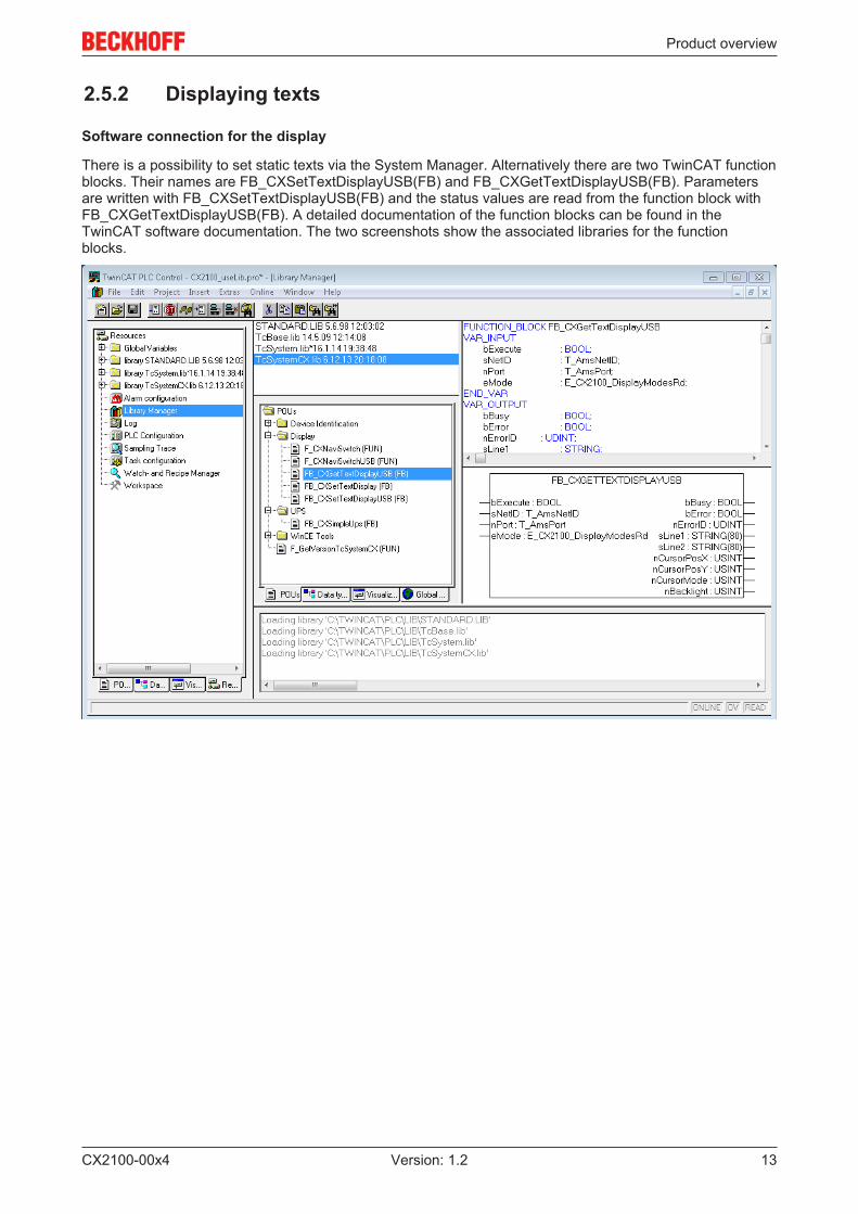
Software connection for the display
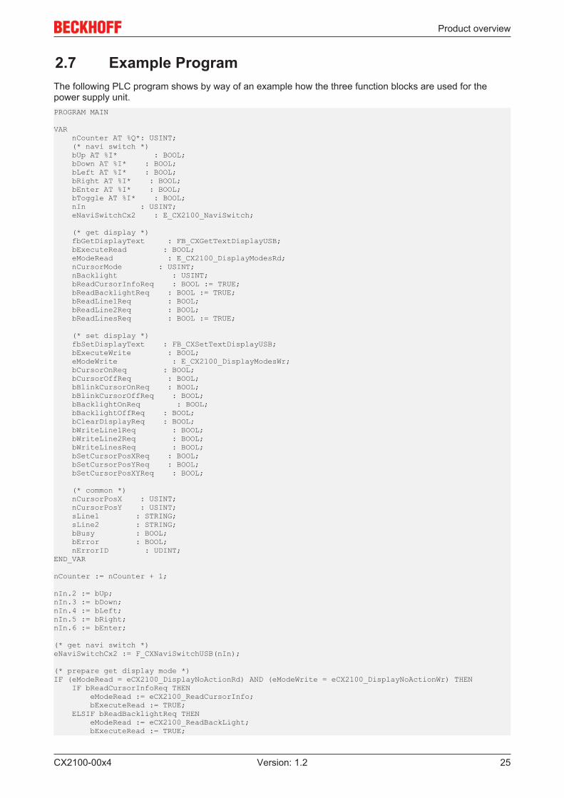
There is a possibility to set static texts via the System Manager. Alternatively there are two TwinCAT functionblocks. Their names are FB_CXSetTextDisplayUSB(FB) and FB_CXGetTextDisplayUSB(FB). Parametersare written with FB_CXSetTextDisplayUSB(FB) and the status values are read from the function block withFB_CXGetTextDisplayUSB(FB). A detailed documentation of the function blocks can be found in theTwinCAT software documentation. The two screenshots show the associated libraries for the functionblocks.

Product overview
CX2100-00x414 Version: 1.2
Note
Availability of the function blocksThese function blocks are available in the TwinCAT builds starting from versionTC2.11 R3 Build 2240TC3.1 Build 4015With older versions an update is required for the use of the function blocks.
Illustration of the display with the System Manager
There are six tabs in the System Manager. These are briefly described below. The focus is thereby placedon the parameter that is relevant for the power supply unit
Tab: General
The general properties of the power supply unit are displayed here.

Product overview
CX2100-00x4 15Version: 1.2
Name Name of the EtherCAT deviceId Number of the EtherCAT deviceType EtherCAT device typeComment Here you can add a comment (e.g. regarding the system).Disabled Here you can deactivate the EtherCAT device.
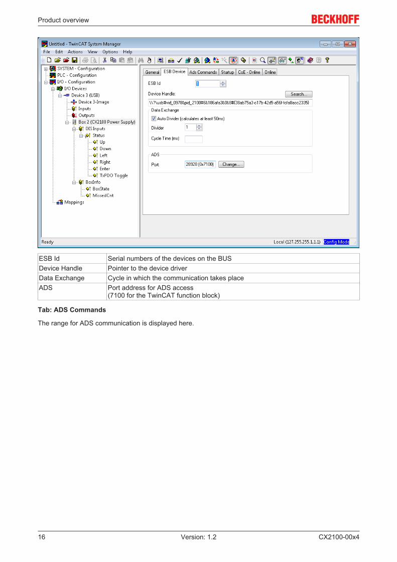
Tab: ESB Device
The settings for the exchange of data between the power supply unit and the system are made and/ordisplayed here.
Product overview
CX2100-00x416 Version: 1.2
ESB Id Serial numbers of the devices on the BUSDevice Handle Pointer to the device driverData Exchange Cycle in which the communication takes placeADS Port address for ADS access
(7100 for the TwinCAT function block)
Tab: ADS Commands
The range for ADS communication is displayed here.

Product overview
CX2100-00x4 17Version: 1.2
Tab: CoE Online

Product overview
CX2100-00x418 Version: 1.2
CoE interface – parameter management in the EtherCAT system
Many different devices are used in an automation environment. These devices can be used separately ortogether in a group on a bus system. Such devices can be controllers, shaft encoders, servo drives, motors,I/O modules or sensors among other things. Depending upon complexity, such a device must beparameterizable/adjustable for the respective requirement. Parameterization is perhaps not necessary in thecase of a simple digital 24 V input with a fixed switching threshold and delay; in the case of a shaft encoder,however, it will not be possible to do without it (e.g. number of lines, absolute or relative, data format, etc.)On top of that it can be of interest to store data in the device during production or operation. Themanufacturer could store production data such as device name, serial number, firmware version, calibrationdata or date of manufacture, if necessary provided with protection against access or amendment. The usercould store user calibration data and the application-specific settings in the device.In order to create a user-friendly interface for device operation, different organizations have created variousstandards in which the following are defined: the available device classes (e.g.: ‘rotary encoder’, ‘analoginput module’ class), the parameters that each representative of such a class has (obligatory and optionalelements), the locations where these parameters can be found and the mechanism with which they are to bechanged. EtherCAT follows the so called CoE standard here: Can-Application-protocol-over-EtherCAT.
Can-over-EtherCAT
The CiA organization (CAN in Automation) pursues among other things the goal of creating order andexchangeability between devices of the same type by the standardization of device descriptions. For thispurpose so-called profiles are defined, which conclusively describe the changeable and unchangeableparameters of a device. Such a parameter encompasses at least the following characteristics:
• Index number – for the unambiguous identification of all parameters. The index number is divided intoa main index and a subindex in order to mark and arrange associated parameters.- Main index- Subindex, (offset by a colon “:”)
• Official name – in the form of an understandable, self-descriptive text• Specification of changeability, e.g. whether it can only be read or can also be written• A value – depending upon the parameter the value can be a text, a number or another parameter
index.
Example: the parameter ‘Vendor ID’ might have the index number 4120:01 and the numerical value ‘2’ as theID of a Beckhoff device.Since hexadecimal values are favored in the machine environment, the parameter is represented from theuser’s point of view as if it had the RO property (read only), because the vendor ID should not be changed bythe user.
Such a list of parameters, the whole of the device-specific CoE directory, can become very extensive. Thefirst entries of a Beckhoff EL3152 analog input terminal appear as follows in the TwinCAT System Manager:
The index numbers are specified in the profile; they begin in EtherCAT with x1000, because the underlyingentries do not have to be displayed.
CoE directory – availability
An EtherCAT device can have a CoE directory, but does not need to have one. Simple slaves need noparameter directory or do not have the controller required for administration. On the other hand, theEtherCAT master (like TwinCAT) as a software EtherCAT device can also manage a CoE directory.
If present, the CoE directory is in operation from the PREOP state.
The object directory can be read via the SDO information service (Service Data Objects).
CoE directory – localization in the EtherCAT Slave
The CoE directory as a parameter system must be administrated in the device in the firmware (FW) in thelocal controller. This is the so-called online directory, because it is only available to the user if the EtherCATslave is in operation with operating voltage supplied and, if applicable, can be manipulated via EtherCATcommunication.
Product overview
CX2100-00x4 19Version: 1.2
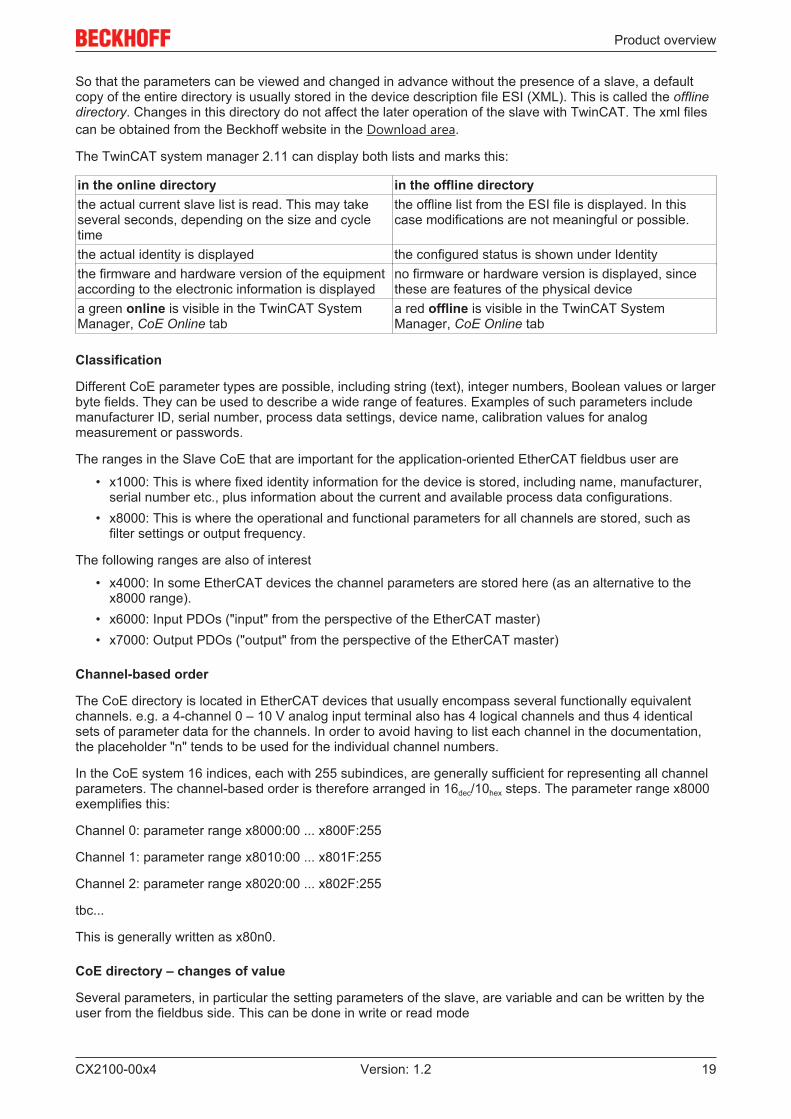
So that the parameters can be viewed and changed in advance without the presence of a slave, a defaultcopy of the entire directory is usually stored in the device description file ESI (XML). This is called the offlinedirectory. Changes in this directory do not affect the later operation of the slave with TwinCAT. The xml filescan be obtained from the Beckhoff website in the Download area.
The TwinCAT system manager 2.11 can display both lists and marks this:
in the online directory in the offline directorythe actual current slave list is read. This may takeseveral seconds, depending on the size and cycletime
the offline list from the ESI file is displayed. In thiscase modifications are not meaningful or possible.
the actual identity is displayed the configured status is shown under Identitythe firmware and hardware version of the equipmentaccording to the electronic information is displayed
no firmware or hardware version is displayed, sincethese are features of the physical device
a green online is visible in the TwinCAT SystemManager, CoE Online tab
a red offline is visible in the TwinCAT SystemManager, CoE Online tab
Classification
Different CoE parameter types are possible, including string (text), integer numbers, Boolean values or largerbyte fields. They can be used to describe a wide range of features. Examples of such parameters includemanufacturer ID, serial number, process data settings, device name, calibration values for analogmeasurement or passwords.
The ranges in the Slave CoE that are important for the application-oriented EtherCAT fieldbus user are
• x1000: This is where fixed identity information for the device is stored, including name, manufacturer,serial number etc., plus information about the current and available process data configurations.
• x8000: This is where the operational and functional parameters for all channels are stored, such asfilter settings or output frequency.
The following ranges are also of interest
• x4000: In some EtherCAT devices the channel parameters are stored here (as an alternative to thex8000 range).
• x6000: Input PDOs ("input" from the perspective of the EtherCAT master)• x7000: Output PDOs ("output" from the perspective of the EtherCAT master)
Channel-based order
The CoE directory is located in EtherCAT devices that usually encompass several functionally equivalentchannels. e.g. a 4-channel 0 – 10 V analog input terminal also has 4 logical channels and thus 4 identicalsets of parameter data for the channels. In order to avoid having to list each channel in the documentation,the placeholder "n" tends to be used for the individual channel numbers.
In the CoE system 16 indices, each with 255 subindices, are generally sufficient for representing all channelparameters. The channel-based order is therefore arranged in 16dec/10hex steps. The parameter range x8000exemplifies this:
Channel 0: parameter range x8000:00 ... x800F:255
Channel 1: parameter range x8010:00 ... x801F:255
Channel 2: parameter range x8020:00 ... x802F:255
tbc...
This is generally written as x80n0.
CoE directory – changes of value
Several parameters, in particular the setting parameters of the slave, are variable and can be written by theuser from the fieldbus side. This can be done in write or read mode
Product overview
CX2100-00x420 Version: 1.2
via the System Manager (fig. 3) by the operator clicking on it The values are then changed directly in the online-connected slave. This is useful for commissioning of the system/slaves. Click on the row of the index to be parameterized andenter a value in the "SetValue" dialog.
from the controller/PLC via ADS e.g. by the function blocks from the TcEtherCAT.lib libraryThis is recommended for modifications when the system is running or if no System Manager or operatingstaff are available.
during the EtherCAT startup through predefined commands, the so-called startup list.The TwinCAT configuration is usually created in advance without EtherCAT slaves actually being present.Then it should be possible before commissioning to adjust known properties such as filter settings offline inorder to accelerate commissioning.
CoE directory – startup list
Note
Start-up listChanges made to the local CoE directory of the EtherCAT slaves are lost with the old de-vice in case of exchange. If a device is replaced with a new Beckhoff device, it will have thedefault settings. It is therefore advisable to link all changes in the CoE list of an EtherCATslave with the Startup list of the slave, which is processed whenever the EtherCAT fieldbusis started. In this way a replacement EtherCAT slave can automatically be parameterizedwith the specifications of the user.If EtherCAT slaves are used which are unable to store local CoE values permanently, theStartup list must be used.
The startup list is used for these cases: the values here, which are entered by the user, are transmitted tothe respective slave upon each EtherCAT state transition/start. A startup entry consists of
• Time: the state transition in which the command is sentPS (PREOP-->SAFEOP) is usually the correct choice, since an EtherCAT slave then switches tooperative input mode.
• Index:Subindex• Data
The order of the entries is not taken into account: all entries to which a state transition applies are handedover simultaneously as asynchronous commands to the EtherCAT system and executed there, as soon asthe bus load allows. No check is made of whether an identical entry is already present in the slave. Thecorresponding values are adopted upon clicking the entry 8000:01; 01 is entered in Data as the desiredvalue. The entry ‘P->S’ marks the time of the execution.
CoE directory – data management
Note
Data managementIf slave CoE parameters are modified online, Beckhoff devices store any changes in a fail-safe manner in the EEPROM, i.e. the modified CoE parameters are still available after arestart.The situation may be different with other manufacturers.If EtherCAT slaves are used which are unable to store local CoE values permanently, theStartup list must be used.
Summary of the characteristics
Not every EtherCAT device must have a CoE directory
If a CoE directory is present, it is administrated, prepared for querying and writing and stored in the device bythe controller.
The EtherCAT master can be used for viewing/querying/changing, or a local user interface on the device(keypad, screen) allows access.
Product overview
CX2100-00x4 21Version: 1.2
Changed settings are stored fail-safe in Beckhoff devices.If the device is later exchanged, however, the settings that have been changed from the series standard arelost. The EtherCAT master can then load the changed CoE parameters into the new device at startup, if it isset up appropriately.
So that a CoE directory is available offline during the preparation for configuration, it can be contained in thedevice description as a copy.
The extent to which the CoE directory is supported depends on the capabilities of the EtherCAT master.
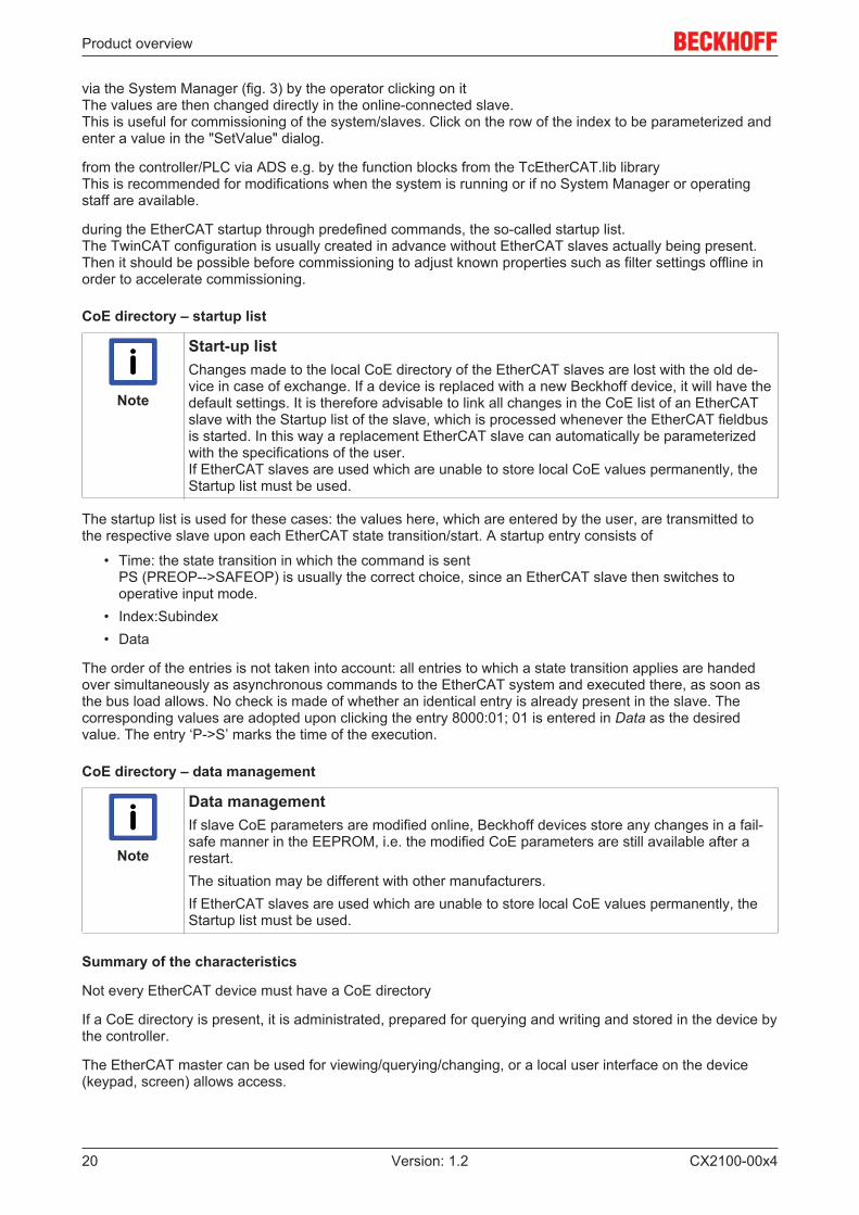
Tab: Online
the state machine of the EtherCAT communication is displayed here. It can also be switched to a differentstate here. This is done by selecting the desired state by a mouse-click on the appropriate button. Theindividual states are briefly described below. For further information, please refer to the EtherCAT systemdescription on our webpage.
EtherCAT State Machine
The state of the EtherCAT slave is controlled via the EtherCAT State Machine (ESM). Depending upon thestate, different functions are accessible or executable in the EtherCAT slave. Specific commands must besent by the EtherCAT master to the device in each state, particularly during the bootup of the slave.
A distinction is made between the following states:
• Init• Pre-Operational• Safe-Operational and• Operational• Boot
The regular state of each EtherCAT slave after bootup is the OP state.

Product overview
CX2100-00x422 Version: 1.2
Init
After switch-on the EtherCAT slave in the Init state. No mailbox or process data communication is possible.The EtherCAT master initializes sync manager channels 0 and 1 for mailbox communication.
Pre-Operational (Pre-Op)
During the transition from Init to Pre-Op, the EtherCAT slave checks whether the mailbox has been correctlyinitialized. Mailbox communication is possible in the Pre-Op state, but no process data communication. TheEtherCAT master initializes the sync manager channels for process data (from sync manager channel 2), theFMMU channels and, if the slave supports configurable mapping, PDO mapping or the sync manager PDOassignment. In this state the settings for the process data transfer and perhaps terminal-specific parametersthat may differ from the default settings are also transferred.
Safe-Operational (Safe-Op)
During transition between Pre-Op and Safe-Op the EtherCAT slave checks whether the sync managerchannels for process data communication and, if required, the distributed clocks settings are correct. Beforeit acknowledges the change of state, the EtherCAT slave copies current input data into the associated DP-RAM areas of the EtherCAT slave controller (ECSC).
Mailbox and process data communication are possible in the Safe-OP state; however, the slave maintains itsoutputs in the safe state and does not output them. The input data, however, are already cyclically updated.
Operational (Op)
Before the EtherCAT master switches the EtherCAT Slave from Safe-Op to Op, it must transmit already validoutput data. In the Op state the slave copies the output data of the master to its outputs. Process data andmailbox communication is possible.
Boot
In the Boot state the slave firmware can be updated. The Boot state can only be reached via the Init state. Inthe Boot state mailbox communication is possible via the File-Access over EtherCAT (FoE) protocol, but noother mailbox communication and no process data communication is possible.
Product overview
CX2100-00x4 23Version: 1.2
2.6 Button
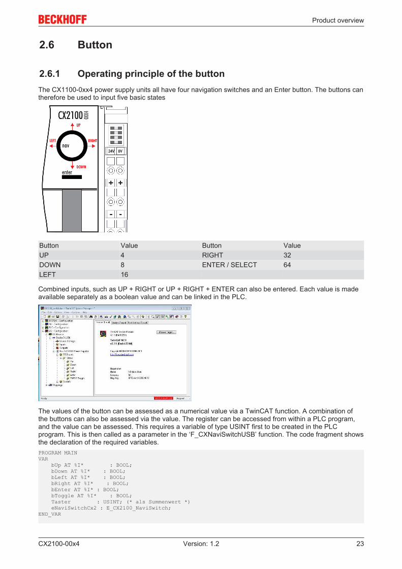
2.6.1 Operating principle of the buttonThe CX1100-0xx4 power supply units all have four navigation switches and an Enter button. The buttons cantherefore be used to input five basic states
Button Value Button ValueUP 4 RIGHT 32DOWN 8 ENTER / SELECT 64LEFT 16
Combined inputs, such as UP + RIGHT or UP + RIGHT + ENTER can also be entered. Each value is madeavailable separately as a boolean value and can be linked in the PLC.
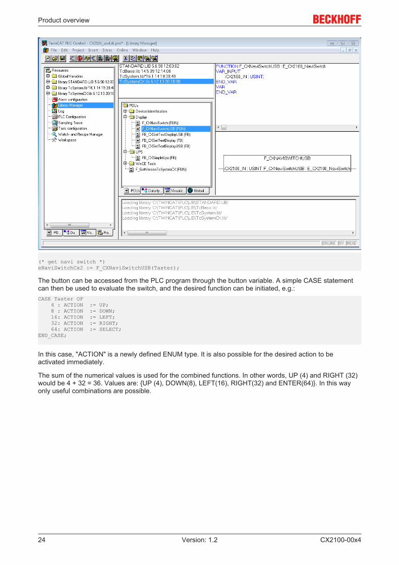
The values of the button can be assessed as a numerical value via a TwinCAT function. A combination ofthe buttons can also be assessed via the value. The register can be accessed from within a PLC program,and the value can be assessed. This requires a variable of type USINT first to be created in the PLCprogram. This is then called as a parameter in the ‘F_CXNaviSwitchUSB’ function. The code fragment showsthe declaration of the required variables.PROGRAM MAINVAR bUp AT %I* : BOOL; bDown AT %I* : BOOL; bLeft AT %I* : BOOL; bRight AT %I* : BOOL; bEnter AT %I* : BOOL; bToggle AT %I* : BOOL; Taster : USINT; (* als Summenwert *) eNaviSwitchCx2 : E_CX2100_NaviSwitch;END_VAR
Product overview
CX2100-00x424 Version: 1.2
(* get navi switch *)eNaviSwitchCx2 := F_CXNaviSwitchUSB(Taster);
The button can be accessed from the PLC program through the button variable. A simple CASE statementcan then be used to evaluate the switch, and the desired function can be initiated, e.g.:CASE Taster OF 4 : ACTION := UP; 8 : ACTION := DOWN; 16: ACTION := LEFT; 32: ACTION := RIGHT; 64: ACTION := SELECT;END_CASE;
In this case, "ACTION" is a newly defined ENUM type. It is also possible for the desired action to beactivated immediately.
The sum of the numerical values is used for the combined functions. In other words, UP (4) and RIGHT (32)would be 4 + 32 = 36. Values are: {UP (4), DOWN(8), LEFT(16), RIGHT(32) and ENTER(64)}. In this wayonly useful combinations are possible.
Product overview
CX2100-00x4 25Version: 1.2
2.7 Example ProgramThe following PLC program shows by way of an example how the three function blocks are used for thepower supply unit.PROGRAM MAIN
VAR nCounter AT %Q*: USINT; (* navi switch *) bUp AT %I* : BOOL; bDown AT %I* : BOOL; bLeft AT %I* : BOOL; bRight AT %I* : BOOL; bEnter AT %I* : BOOL; bToggle AT %I* : BOOL; nIn : USINT; eNaviSwitchCx2 : E_CX2100_NaviSwitch;
(* get display *) fbGetDisplayText : FB_CXGetTextDisplayUSB; bExecuteRead : BOOL; eModeRead : E_CX2100_DisplayModesRd; nCursorMode : USINT; nBacklight : USINT; bReadCursorInfoReq : BOOL := TRUE; bReadBacklightReq : BOOL := TRUE; bReadLine1Req : BOOL; bReadLine2Req : BOOL; bReadLinesReq : BOOL := TRUE;
(* set display *) fbSetDisplayText : FB_CXSetTextDisplayUSB; bExecuteWrite : BOOL; eModeWrite : E_CX2100_DisplayModesWr; bCursorOnReq : BOOL; bCursorOffReq : BOOL; bBlinkCursorOnReq : BOOL; bBlinkCursorOffReq : BOOL; bBacklightOnReq : BOOL; bBacklightOffReq : BOOL; bClearDisplayReq : BOOL; bWriteLine1Req : BOOL; bWriteLine2Req : BOOL; bWriteLinesReq : BOOL; bSetCursorPosXReq : BOOL; bSetCursorPosYReq : BOOL; bSetCursorPosXYReq : BOOL;
(* common *) nCursorPosX : USINT; nCursorPosY : USINT; sLine1 : STRING; sLine2 : STRING; bBusy : BOOL; bError : BOOL; nErrorID : UDINT;END_VAR
nCounter := nCounter + 1;
nIn.2 := bUp;nIn.3 := bDown;nIn.4 := bLeft;nIn.5 := bRight;nIn.6 := bEnter;
(* get navi switch *)eNaviSwitchCx2 := F_CXNaviSwitchUSB(nIn);
(* prepare get display mode *)IF (eModeRead = eCX2100_DisplayNoActionRd) AND (eModeWrite = eCX2100_DisplayNoActionWr) THEN IF bReadCursorInfoReq THEN eModeRead := eCX2100_ReadCursorInfo; bExecuteRead := TRUE; ELSIF bReadBacklightReq THEN eModeRead := eCX2100_ReadBackLight; bExecuteRead := TRUE;

Product overview
CX2100-00x426 Version: 1.2
ELSIF bReadLine1Req THEN eModeRead := eCX2100_ReadLine1; bExecuteRead := TRUE; ELSIF bReadLine2Req THEN eModeRead := eCX2100_ReadLine2; bExecuteRead := TRUE; ELSIF bReadLinesReq THEN eModeRead := eCX2100_ReadLines; bExecuteRead := TRUE; END_IFEND_IF
(* get display *)
IF (eModeRead <> eCX2100_DisplayNoActionRd) AND (eModeWrite = eCX2100_DisplayNoActionWr) THEN fbGetDisplayText( bExecute := bExecuteRead, sNetID := '', nPort := 16#7100, eMode := eModeRead, bBusy => bBusy, bError => bError, nErrorID => nErrorID, ); IF NOT fbGetDisplayText.bBusy THEN fbGetDisplayText(bExecute := FALSE); IF NOT fbGetDisplayText.bError THEN CASE eModeRead OF eCX2100_ReadCursorInfo: nCursorPosX := fbGetDisplayText.nCursorPosX; nCursorPosY := fbGetDisplayText.nCursorPosY; nCursorMode := fbGetDisplayText.nCursorMode; bReadCursorInfoReq := FALSE; eCX2100_ReadBackLight: nBacklight := fbGetDisplayText.nBacklight; bReadBacklightReq := FALSE; eCX2100_ReadLine1: sLine1 := fbGetDisplayText.sLine1; bReadLine1Req := FALSE; eCX2100_ReadLine2:‘ sLine2 := fbGetDisplayText.sLine2; bReadLine2Req := FALSE; eCX2100_ReadLines: sLine1 := fbGetDisplayText.sLine1; sLine2 := fbGetDisplayText.sLine2; bReadLinesReq := FALSE; END_CASE END_IF
bExecuteRead := FALSE; eModeRead := eCX2100_DisplayNoActionRd; END_IFEND_IF
(* prepare set display mode *)IF (eModeWrite = eCX2100_DisplayNoActionWr) AND (eModeRead = eCX2100_DisplayNoActionRd) THEN IF bCursorOnReq THEN eModeWrite := eCX2100_CursorOn; bExecuteWrite := TRUE; bReadCursorInfoReq := TRUE; ELSIF bCursorOffReq THEN eModeWrite := eCX2100_CursorOff; bExecuteWrite := TRUE; bReadCursorInfoReq := TRUE; ELSIF bBlinkCursorOnReq THEN eModeWrite := eCX2100_CursorBlinkOn; bExecuteWrite := TRUE; bReadCursorInfoReq := TRUE; ELSIF bBlinkCursorOffReq THEN eModeWrite := eCX2100_CursorBlinkOff; bExecuteWrite := TRUE; bReadCursorInfoReq := TRUE; ELSIF bBacklightOnReq THEN eModeWrite := eCX2100_BackLightOn; bExecuteWrite := TRUE; bReadBacklightReq := TRUE; ELSIF bBacklightOffReq THEN eModeWrite := eCX2100_BackLightOff; bExecuteWrite := TRUE; bReadBacklightReq := TRUE;

Product overview
CX2100-00x4 27Version: 1.2
ELSIF bClearDisplayReq THEN eModeWrite := eCX2100_ClearDisplay; bExecuteWrite := TRUE; bReadLinesReq := TRUE; ELSIF bWriteLine1Req THEN eModeWrite := eCX2100_WriteLine1; bExecuteWrite := TRUE; bReadLine1Req := TRUE; ELSIF bWriteLine2Req THEN eModeWrite := eCX2100_WriteLine2; bExecuteWrite := TRUE; bReadLine2Req := TRUE; ELSIF bWriteLinesReq THEN eModeWrite := eCX2100_WriteLines; bExecuteWrite := TRUE; bReadLinesReq := TRUE; ELSIF bSetCursorPosXReq THEN eModeWrite := eCX2100_CursorPosX; bExecuteWrite := TRUE; bReadCursorInfoReq := TRUE; ELSIF bSetCursorPosYReq THEN eModeWrite := eCX2100_CursorPosY; bExecuteWrite := TRUE; bReadCursorInfoReq := TRUE; ELSIF bSetCursorPosXYReq THEN eModeWrite := eCX2100_CursorPosXY; bExecuteWrite := TRUE; bReadCursorInfoReq := TRUE; END_IFEND_IF
(* set display *)IF (eModeWrite <> eCX2100_DisplayNoActionWr) AND (eModeRead = eCX2100_DisplayNoActionRd) THEN fbSetDisplayText( bExecute := bExecuteWrite, sNetID := '', nPort := 16#7100, eMode := eModeWrite, sLine1 := sLine1, sLine2 := sLine2, nCursorPosX := nCursorPosX, nCursorPosY := nCursorPosY, bBusy => bBusy, bError => bError, nErrorID => nErrorID ); IF NOT fbSetDisplayText.bBusy THEN fbSetDisplayText(bExecute := FALSE);
bExecuteWrite := FALSE; eModeWrite := eCX2100_DisplayNoActionWr; END_IFEND_IF
Transport
CX2100-00x428 Version: 1.2
3 Transport
3.1 Unpacking, installation and transportDimensions and weight of the individual modules:
CX2100-0004:
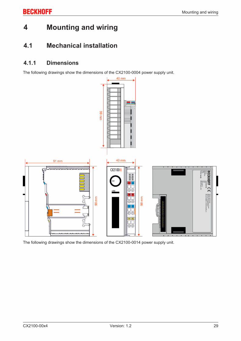
Dimensions (W x H x D): 40 mm x 99 mm x 91 mm
Weight: approx. 375 g (system interface)
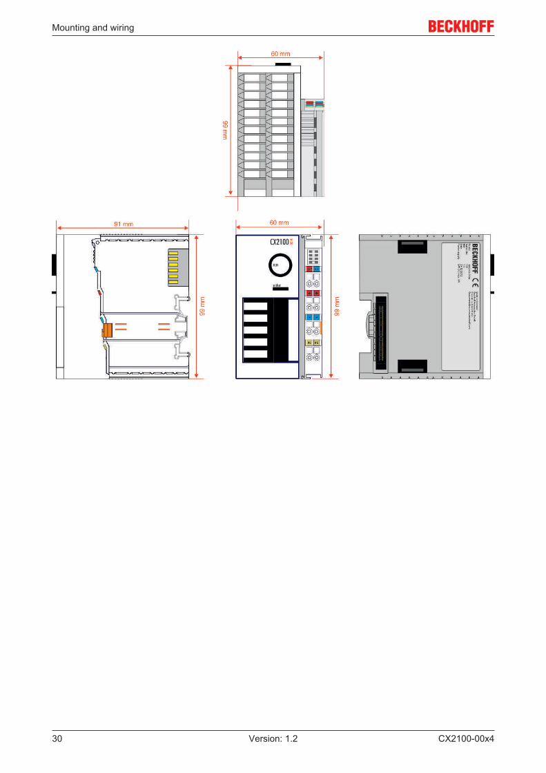
CX2100-0014:
Dimensions (W x H x D): 60 mm x 99 mm x 91 mm
Weight: approx. 550 g (system interface)
The specified storage conditions must be adhered to (see "Technical data").
Unpacking
Proceed as follows to unpack the unit:
1. Remove packaging.2. Do not discard the original packaging. Keep it for transporting the device in the future.3. Check the delivery for completeness by comparing it with your order.4. Please keep the associated paperwork. It contains important information for handling the unit.5. Check the contents for visible shipping damage.6. If you notice any shipping damage or inconsistencies between the contents and your order, you
should notify Beckhoff Service.
Attention
Danger of damage to the device!During transport in cold conditions, or if the device is subjected to extreme temperature dif-ferences, condensation on and inside the device must be avoided. Prior to operation, thedevice must be allowed to slowly adjust to room temperature. Should condensation occur,a delay time of approximately 12 hours must be allowed before the unit is switched on.
Installation
The devices are designed for installation in control cabinets.
Shipping and relocation
Despite the robust design of the unit, the components are sensitive to strong vibrations and impacts. Duringtransport, your computer should therefore be protected from excessive mechanical stress. Therefore, pleaseuse the original packaging.
Mounting and wiring
CX2100-00x4 29Version: 1.2
4 Mounting and wiring
4.1 Mechanical installation
4.1.1 DimensionsThe following drawings show the dimensions of the CX2100-0004 power supply unit.
The following drawings show the dimensions of the CX2100-0014 power supply unit.
Mounting and wiring
CX2100-00x430 Version: 1.2

Mounting and wiring
CX2100-00x4 31Version: 1.2
4.2 Commissioning
4.2.1 Power supplyThis power supply unit is equipped with an I/O interface, which permits connection of the Beckhoff BusTerminals. The power is supplied via the upper spring-loaded terminals labelled “24V” and “0V”.The supply voltage supplies the CX system ant the terminal Bus and Bus Terminal with a voltage of 24 V DC(-15%/+20 %). The dielectric strength of the power supply unit is 500Veff. Since the Terminal Bus (K- and E-bus) only transfers data, a separate power supply is required for the Bus Terminals. This is provided bymeans of the power contacts, which are not connected to the power supply.
CX2100-004:
CX2100-014:
Requirements for the 24V power supply
In order to guarantee the operation of the CPU (CX20x0 module) and the terminal strand in all cases, thepower supply must supply 4 A at 24 V.

Mounting and wiring
CX2100-00x432 Version: 1.2
The terminals are implemented in spring force technology. Connect the cables as follows:
1. Open a spring-loaded terminal by slightly pushing with a screwdriver or a rod into the square openingabove the terminal.
2. The wire can now be inserted into the round terminal opening without any force.3. The terminal closes automatically when the pressure is released, holding the wire safely and perma-
nently.
Wire cross section 0.5... 2.5 mm2 AWG 20 .. AWG 14Strip length 8 ... 9 mm 0.33 inch
LED
If the power supply unit is connected correctly and the power supply is switched on, the two upper LEDs inthe terminal prism are green. The left LED (Us) indicates the CPU supply. The right LED (Up) indicates theterminal supply. The other LEDs indicate the Terminal Bus status. A detailed description of the LEDs can befound in section “LED troubleshooting”.
UL requirements
DANGER
Compliance of the UL requirementsFor the compliance of the UL requirements the CX-Controllers should only be supplied by a24 VDC supply voltage, supplied by an isolating source and protected by means of a fuse(in accordance with UL248), rated maximum 4 Amp.by a 24 VDC power source, that has tosatisfy NEC class 2. A NEC class 2 power supply shall not be connected in series or paral-lel with another (class 2) power source!This UL requirements are valid for all supply volt-ages of the CX-Controllers!
DANGER
Compliance of the UL requirementsTo meet the UL requirements, the CX-Controllers must not be connected to unlimitedpower sources!
PE power contacts
Attention
Power contact “PE”The “PE” power contact must not be used for other potentials. “PE” and “0V” (24 V systemsupply) must be at the same potential (connected in the control cabinet). The cabling in thecontrol cabinet must be done in accordance with the standard EN 60204-1:2006 PELV =Protective Extra Low Voltage. EN 60204-1:2006 section 6.4.1:b: one side of the circuit orone point of the energy source of this circuit must be connected to the protective conductorsystem.

Mounting and wiring
CX2100-00x4 33Version: 1.2
Attention
Interruption of the power supply / switching offThe device may not be switched off by disconnecting the ground. The 24 V line must al-ways be disconnected, as otherwise current may continue to flow via the screen dependingon the device. Any connected devices with their own power supply (e.g. a panel) must havethe same potential for “PE” and “GND” as the CX system (no potential difference). Other-wise damage can occur both to the controller and to the periphery.
Mounting and wiring
CX2100-00x434 Version: 1.2
4.3 Installation on the mounting rail
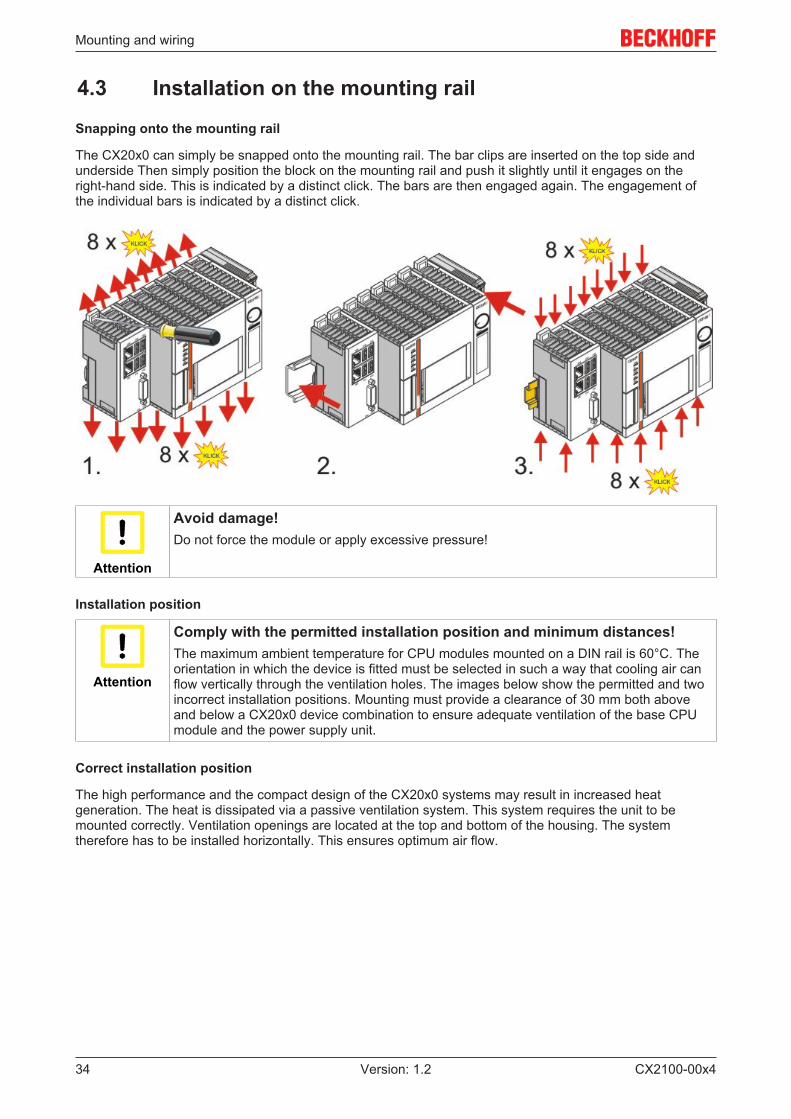
Snapping onto the mounting rail
The CX20x0 can simply be snapped onto the mounting rail. The bar clips are inserted on the top side andunderside Then simply position the block on the mounting rail and push it slightly until it engages on theright-hand side. This is indicated by a distinct click. The bars are then engaged again. The engagement ofthe individual bars is indicated by a distinct click.
Attention
Avoid damage!Do not force the module or apply excessive pressure!
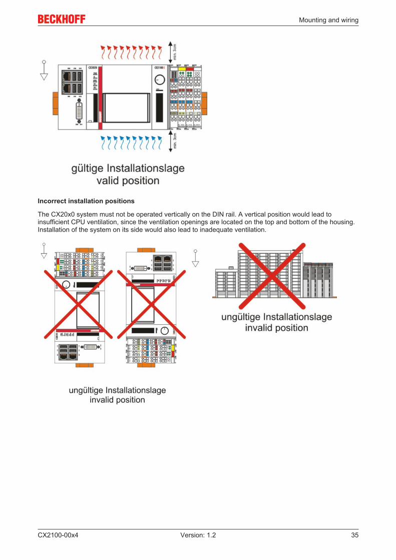
Installation position
Attention
Comply with the permitted installation position and minimum distances!The maximum ambient temperature for CPU modules mounted on a DIN rail is 60°C. Theorientation in which the device is fitted must be selected in such a way that cooling air canflow vertically through the ventilation holes. The images below show the permitted and twoincorrect installation positions. Mounting must provide a clearance of 30 mm both aboveand below a CX20x0 device combination to ensure adequate ventilation of the base CPUmodule and the power supply unit.
Correct installation position
The high performance and the compact design of the CX20x0 systems may result in increased heatgeneration. The heat is dissipated via a passive ventilation system. This system requires the unit to bemounted correctly. Ventilation openings are located at the top and bottom of the housing. The systemtherefore has to be installed horizontally. This ensures optimum air flow.
Mounting and wiring
CX2100-00x4 35Version: 1.2
Incorrect installation positions
The CX20x0 system must not be operated vertically on the DIN rail. A vertical position would lead toinsufficient CPU ventilation, since the ventilation openings are located on the top and bottom of the housing.Installation of the system on its side would also lead to inadequate ventilation.
Mounting and wiring
CX2100-00x436 Version: 1.2
4.4 Mounting the module lock
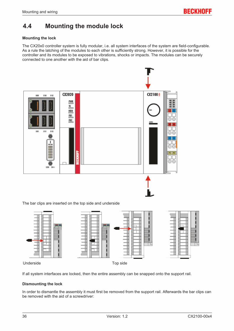
Mounting the lock
The CX20x0 controller system is fully modular, i.e. all system interfaces of the system are field-configurable.As a rule the latching of the modules to each other is sufficiently strong. However, it is possible for thecontroller and its modules to be exposed to vibrations, shocks or impacts. The modules can be securelyconnected to one another with the aid of bar clips.
The bar clips are inserted on the top side and underside
Underside Top side
If all system interfaces are locked, then the entire assembly can be snapped onto the support rail.
Dismounting the lock
In order to dismantle the assembly it must first be removed from the support rail. Afterwards the bar clips canbe removed with the aid of a screwdriver:
Mounting and wiring
CX2100-00x4 37Version: 1.2
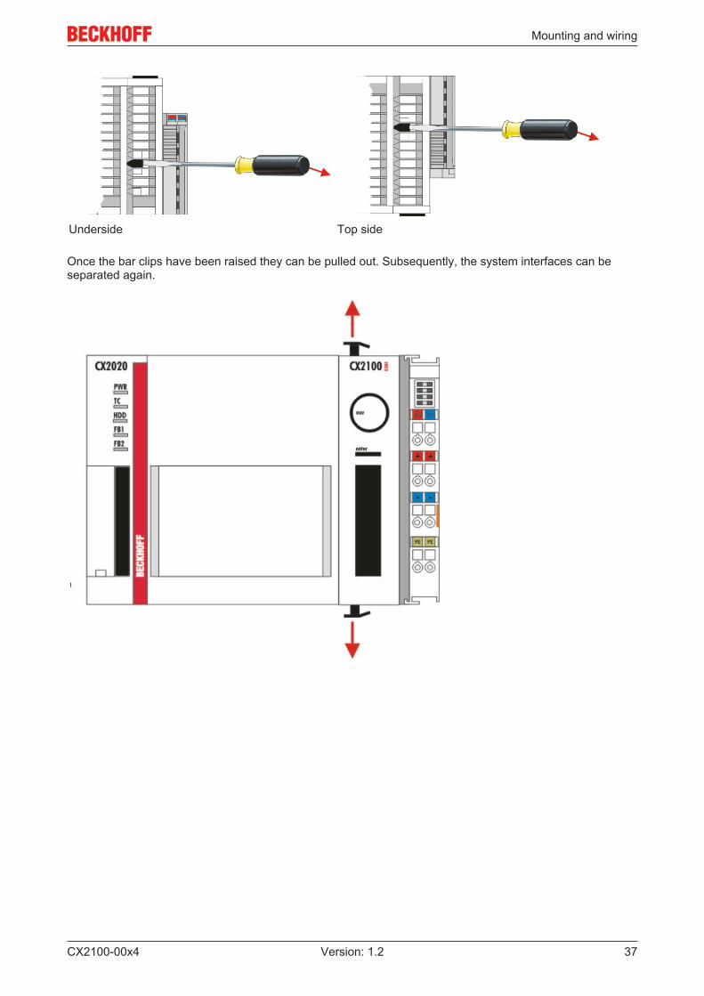
Underside Top side
Once the bar clips have been raised they can be pulled out. Subsequently, the system interfaces can beseparated again.
Mounting and wiring
CX2100-00x438 Version: 1.2
4.5 Mounting of passive terminals on the CX2100-0xx4power supply
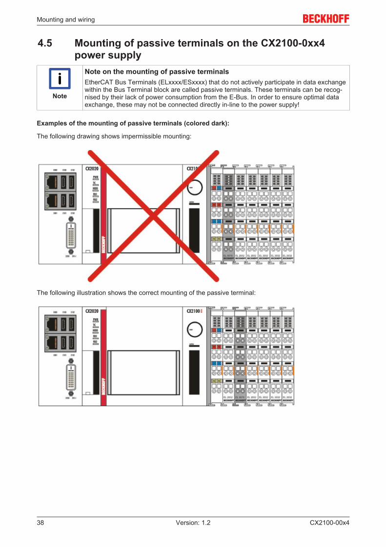
Note
Note on the mounting of passive terminalsEtherCAT Bus Terminals (ELxxxx/ESxxxx) that do not actively participate in data exchangewithin the Bus Terminal block are called passive terminals. These terminals can be recog-nised by their lack of power consumption from the E-Bus. In order to ensure optimal dataexchange, these may not be connected directly in-line to the power supply!
Examples of the mounting of passive terminals (colored dark):
The following drawing shows impermissible mounting:
The following illustration shows the correct mounting of the passive terminal:
Error handling and diagnostics
CX2100-00x4 39Version: 1.2
5 Error handling and diagnostics
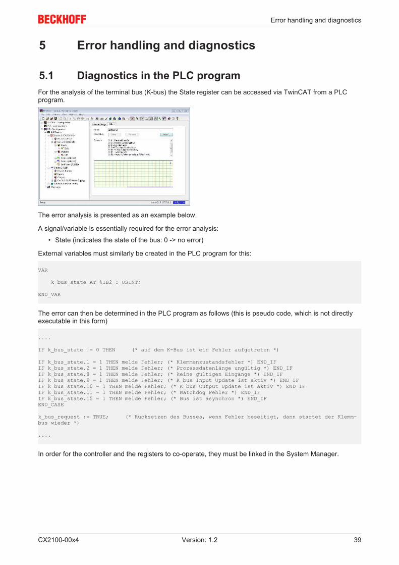
5.1 Diagnostics in the PLC programFor the analysis of the terminal bus (K-bus) the State register can be accessed via TwinCAT from a PLCprogram.
The error analysis is presented as an example below.
A signal/variable is essentially required for the error analysis:
• State (indicates the state of the bus: 0 -> no error)
External variables must similarly be created in the PLC program for this:
VAR
k_bus_state AT %IB2 : USINT;
END_VAR
The error can then be determined in the PLC program as follows (this is pseudo code, which is not directlyexecutable in this form)
....
IF k_bus_state != 0 THEN (* auf dem K-Bus ist ein Fehler aufgetreten *)
IF k_bus_state.1 = 1 THEN melde Fehler; (* Klemmenzustandsfehler *) END_IFIF k_bus_state.2 = 1 THEN melde Fehler; (* Prozessdatenlänge ungültig *) END_IFIF k_bus_state.8 = 1 THEN melde Fehler; (* keine gültigen Eingänge *) END_IFIF k_bus_state.9 = 1 THEN melde Fehler; (* K_bus Input Update ist aktiv *) END_IFIF k_bus_state.10 = 1 THEN melde Fehler; (* K_bus Output Update ist aktiv *) END_IFIF k_bus_state.11 = 1 THEN melde Fehler; (* Watchdog Fehler *) END_IFIF k_bus_state.15 = 1 THEN melde Fehler; (* Bus ist asynchron *) END_IFEND_CASE
k_bus_request := TRUE; (* Rücksetzen des Busses, wenn Fehler beseitigt, dann startet der Klemm-bus wieder *)
....
In order for the controller and the registers to co-operate, they must be linked in the System Manager.

Decommissioning
CX2100-00x440 Version: 1.2
6 Decommissioning
6.1 Disassembly and disposal
The disassembly of a CX20x0 hardware configuration with system interfaces takes place in 3 steps
1. Switching off and disconnecting the power supply
Before a CX20x0 system can be dismantled, the system should be switched off, and the power supplyshould be disconnected.
2. Removing from the DIN rail
Before the individual modules are disconnected, the whole CX20x0 hardware block should be removed fromthe DIN rail. Proceed as follows:
2.1. Release and remove the first Terminal next to the power supply unit on the DIN rail.
First remove any wiring from power supply unit and then from the first terminal on the DIN rail next to thepower supply unit. If the wiring is to be reused for another system, it is advisable to make a note of theconnections. Then pull the orange terminal release (see arrow) to release the terminal and pull it out.
2.2. Releasing the CX20x0 systems
In order to release the CX20x0 block, the DIN rail fastening above and below the device must be released.To do this, press the hooks outwards using a screwdriver. An audible click indicates that the device isreleased.

Decommissioning
CX2100-00x4 41Version: 1.2
After pulling on the terminal release of the power supply unit (see arrow) the block can be carefully removedfrom the DIN rail.
Disposal
The device must be fully dismantled in order to dispose of it.
Electronic parts must be disposed of in accordance with national electronics scrap regulations.
3. Disconnecting the system interface
Disconnecting the system modules from the basic module
If the modules are locked, i.e. attached with tie clips, the clips must be released. To this end lift the tie clipswith a screwdriver and pull them out. Subsequently, the system interfaces can be separated again.
Attention
Do not use force to open the device!Opening the module housing by force would destroy it. The devices may only be opened byBeckhoff service personnel.
Appendix
CX2100-00x442 Version: 1.2
7 Appendix
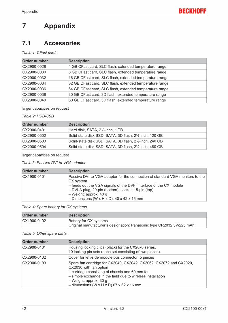
7.1 AccessoriesTable 1: CFast cards
Order number DescriptionCX2900-0028 4 GB CFast card, SLC flash, extended temperature rangeCX2900-0030 8 GB CFast card, SLC flash, extended temperature rangeCX2900-0032 16 GB CFast card, SLC flash, extended temperature rangeCX2900-0034 32 GB CFast card, SLC flash, extended temperature rangeCX2900-0036 64 GB CFast card, SLC flash, extended temperature rangeCX2900-0038 30 GB CFast card, 3D flash, extended temperature rangeCX2900-0040 60 GB CFast card, 3D flash, extended temperature range
larger capacities on request
Table 2: HDD/SSD
Order number DescriptionCX2900-0401 Hard disk, SATA, 2½-inch, 1 TBCX2900-0502 Solid-state disk SSD, SATA, 3D flash, 2½-inch, 120 GBCX2900-0503 Solid-state disk SSD, SATA, 3D flash, 2½-inch, 240 GBCX2900-0504 Solid-state disk SSD, SATA, 3D flash, 2½-inch, 480 GB
larger capacities on request
Table 3: Passive DVI-to-VGA adaptor.
Order number DescriptionCX1900-0101 Passive DVI-to-VGA adaptor for the connection of standard VGA monitors to the
CX system– feeds out the VGA signals of the DVI-I interface of the CX module– DVI-A plug, 29-pin (bottom), socket, 15-pin (top)– Weight: approx. 40 g– Dimensions (W x H x D): 40 x 42 x 15 mm
Table 4: Spare battery for CX systems.
Order number DescriptionCX1900-0102 Battery for CX systems
Original manufacturer’s designation: Panasonic type CR2032 3V/225 mAh
Table 5: Other spare parts.
Order number DescriptionCX2900-0101 Housing locking clips (black) for the CX20x0 series.
10 locking pin sets (each set consisting of two pieces).CX2900-0102 Cover for left-side module bus connector, 5 piecesCX2900-0103 Spare fan cartridge for CX2040, CX2042, CX2062, CX2072 and CX2020,
CX2030 with fan option– cartridge consisting of chassis and 60 mm fan– simple exchange in the field due to wireless installation– Weight: approx. 30 g– dimensions (W x H x D) 67 x 62 x 16 mm
Appendix
CX2100-00x4 43Version: 1.2
7.2 CertificationsAll products of the Embedded PC family are CE, UL and EAC certified. Since the product family iscontinuously developed further, we are unable to provide a full listing here. The current list of certifiedproducts can be found at www.beckhoff.com.
FCC Approvals for the United States of America
FCC: Federal Communications Commission Radio Frequency Interference Statement
This equipment has been tested and found to comply with the limits for a Class A digital device, pursuant toPart 15 of the FCC Rules. These limits are designed to provide reasonable protection against harmfulinterference when the equipment is operated in a commercial environment. This equipment generates, uses,and can radiate radio frequency energy and, if not installed and used in accordance with the instructionmanual, may cause harmful interference to radio communications. Operation of this equipment in aresidential area is likely to cause harmful interference in which case the user will be required to correct theinterference at his own expense.
FCC Approval for Canada
FCC: Canadian Notice
This equipment does not exceed the Class A limits for radiated emissions as described in the RadioInterference Regulations of the Canadian Department of Communications.

Appendix
CX2100-00x444 Version: 1.2
7.3 Support and ServiceBeckhoff and their partners around the world offer comprehensive support and service, making available fastand competent assistance with all questions related to Beckhoff products and system solutions.
Beckhoff's branch offices and representatives
Please contact your Beckhoff branch office or representative for local support and service on Beckhoffproducts!
The addresses of Beckhoff's branch offices and representatives round the world can be found on her internetpages:http://www.beckhoff.com
You will also find further documentation for Beckhoff components there.
Beckhoff Headquarters
Beckhoff Automation GmbH & Co. KG
Huelshorstweg 2033415 VerlGermany
Phone: +49(0)5246/963-0Fax: +49(0)5246/963-198e-mail: [email protected]
Beckhoff Support
Support offers you comprehensive technical assistance, helping you not only with the application ofindividual Beckhoff products, but also with other, wide-ranging services:
• support• design, programming and commissioning of complex automation systems• and extensive training program for Beckhoff system components
Hotline: +49(0)5246/963-157Fax: +49(0)5246/963-9157e-mail: [email protected]
Beckhoff Service
The Beckhoff Service Center supports you in all matters of after-sales service:
• on-site service• repair service• spare parts service• hotline service
Hotline: +49(0)5246/963-460Fax: +49(0)5246/963-479e-mail: [email protected]