manual - itadellabotek.php.dir.dk/userfiles/file/986715_r03.pdf · 4.3 electric connection ......
TRANSCRIPT
MANUAL
Con-Evator SVR-I
Serial No.................... ISO 08.01.02.058.GB
986715 Rev. 03 June 2009

Rev. 03 Con-Evator Page 1
SVR-I
1.0 CONTENS
2.0 GENERAL INFORMATION .............................................................................. 3
2.1 Application ................................................................................................................................ 3 2.2 Restrictions ................................................................................................................................ 3 2.3 Design........................................................................................................................................ 4 2.4 Operating principles .................................................................................................................. 5 2.6. Certificates................................................................................................................................ 7
3.0 TECHNICAL DATA ............................................................................................ 9
3.1 Technical specifications ............................................................................................................ 9 3.2 Typeplate ................................................................................................................................... 9 3.3 Dimensioned drawings ............................................................................................................ 10 3.4 Capacity table .......................................................................................................................... 11 3.6 Noise level ............................................................................................................................... 13
4.0 ASSEMBLY /DISASSEMBLY.......................................................................... 14
4.1 Assembly ................................................................................................................................. 14 4.2 Disassembly............................................................................................................................. 15 4.3 Electric connection .................................................................................................................. 15 4.4 Control ..................................................................................................................................... 15 4.5 Operation ................................................................................................................................. 18 4.6 Start.......................................................................................................................................... 22 4.7 Operation ................................................................................................................................. 22 4.8 Stop.......................................................................................................................................... 22
5.0 ACCESSORIES................................................................................................... 23
5.1 List of accessories.................................................................................................................... 23 5.2 Connecting and installing accessories ..................................................................................... 23
6.0 MAINTENANCE - SVR..................................................................................... 27
6.1 Maintaining the air filter and the base filter ............................................................................ 27 6.2 Maintaining the bottom flap SVR (stainless steel).................................................................. 28 6.3 Adjustment of the magnetic switch ......................................................................................... 28
7.0 TROUBLESHOOTING ..................................................................................... 29
7.1 The Con-Evator does not start ................................................................................................. 29 7.2 The Con-Evator capacity has been reduced ............................................................................ 29 7.3 The Con-Evator stops at short intervals .................................................................................. 29
8.0 REPAIRS ............................................................................................................. 30
8.1 Replacement of fuse for control voltage.................................................................................. 30 8.2 Replacement of bottom flap SVR (stainless steel) .................................................................. 30

Rev. 03 Con-Evator Page 2
SVR-I
NB! All electrical diagrams can be found in the pocket in the back of the manual

Rev. 03 Con-Evator Page 3
SVR-I
2.0 GENERAL INFORMATION
2.1 Application The Con-Evator SVR is a vacuum hopper loader designed for conveying of free-flowing granular plastic material from a bag or bin to the intermediate hopper of the processing machine or another hopper.
2.2 Restrictions The SVR unit may only be used for the purposes specified. The SVR unit can be used neither for powders (only in special version) or liquids, nor for living creatures. The SVR unit must be used by a qualified operator only, following the correct procedures. The blower with motor and control must not be used in a potentially explosive atmosphere. The hopper may only be used in such atmosphere if the bottom flap has been fitted with an explosion-proof power switch. The power switch will be marked with an explosion-proof label. IMPORTANT! The person in charge of the placing/operation and or owner is responsible for the prescribed and adequate installations, corresponding to the local regulations. In other words, only authorized or trained personnel is allowed to install the equipment. Should the equipment be interfered with by unauthorized or untrained personnel leading to damage, or should the consumer allow the equipment to be interfered with in this manner by third parties, then all claims under guarantee relating to the entirety of the object concerned become null and void. The right to carry out changes in design is reserved, without however incurring the obligation to effect such changes, even in equipment already supplied. This information is based on our present state of knowledge and is intended to provide general notes on our products and their uses. It should not therefore be construed as guaranteeing specific properties of the products described or their suitability for particular applications.

Rev. 03 Con-Evator Page 4
SVR-I
2.3 Design Con-Evator SVR comprises Description Pos. Material Control (1) Steel / Material hose (2) Plastic Motor (6) - Blower (7) Cast aluminium Vacuum hose (8) Plastic Bottom flap (13) Stainless Suction hose (14) Electroplated Blow-back valve (80) Cast aluminium Silencer (81) Steel Lid (82) Stainless Hopper (83) Stainless Proximity switch - Base (85) Stainless Base filter (86) Stainless synthetic The Con-Evator is available in the following versions: A) Con-Evator with stainless steel hopper and separate control
Control separated from the machine with an extra long cable. Applicable to locations difficult to access at which adjustment of the control may be impeded or for applications requiring a stainless steel hopper.
R2378_R01

Rev. 03 Con-Evator Page 5
SVR-I
2.4 Operating principles
2.5.1 Conveying (drawing R2369) 1. By means of the blower (7), a vacuum is generated inside the hopper loader (83); the blower
is driven by an electric motor (6). This causes the bottom flap (13) to close against the outlet of the hopper resulting in a vacuum in both the conveying hose (2) and the suction probe (14). Ambient air is consequently sucked in through the outer pipe of the suction probe, carrying material with it to the hopper through the suction pipe (14).
2. BLOWER ON time (the time the blower is required to generate a vacuum) is set at the control.
3. During conveying the conveying hose (2) may be cleared. A line clearing valve located right above the suction probe opens in a preset time integrated in the conveying time. Air is admitted into the system, now via the suction hose instead of the suction probe, and thereby clearing of the hose is effected. See section 5.0 Accessories.
R2369 4. When the blower is turned off the weight of the material sucked into the hopper loader will
cause the bottom flap (13) to be pressed down and the material to fall into the intermediate hopper (5).
5. If there is sufficient room in the intermediate hopper for all the material, the bottom flap will automatically be released against the outlet (15) and indicate to the control, via the bottom flap, that a new loading cycle should be started.
6. If there is insufficient room in the intermediate hopper for all the material, the material will hold the bottom flap down, and a new loading cycle will only be started when the material level has dropped sufficiently to allow the bottom flap to close against the outlet.
2.5.2 Filter cleaning 1. A filter (21), located between the blower (7) and the hopper loader (10), protects the blower
(7) against dust. 2. Immediately before each loading cycle, the filter is automatically cleaned by the blower
reversing its rotating direction. This process also cleans the bottom flap (13).

Rev. 03 Con-Evator Page 6
SVR-I
2a. If a blow-back valve (80) has been fitted, the blower will not reverse its rotating direction, only the position of the valve will switch so to utilize the outlet air of the blower for filter cleaning.
3. The air that is forced down through the hopper loader will be sent out through the base filter (11). The filter will catch any dust/particles that would otherwise be blown into the ambient air.

Rev. 03 Con-Evator Page 7
SVR-I
2.6. Certificates
2.6.1 IQ-Net Certificate

Rev. 03 Con-Evator Page 8
SVR-I
2.6.2 ISO Certificate
Rev. 03 Con-Evator Page 9
SVR-I
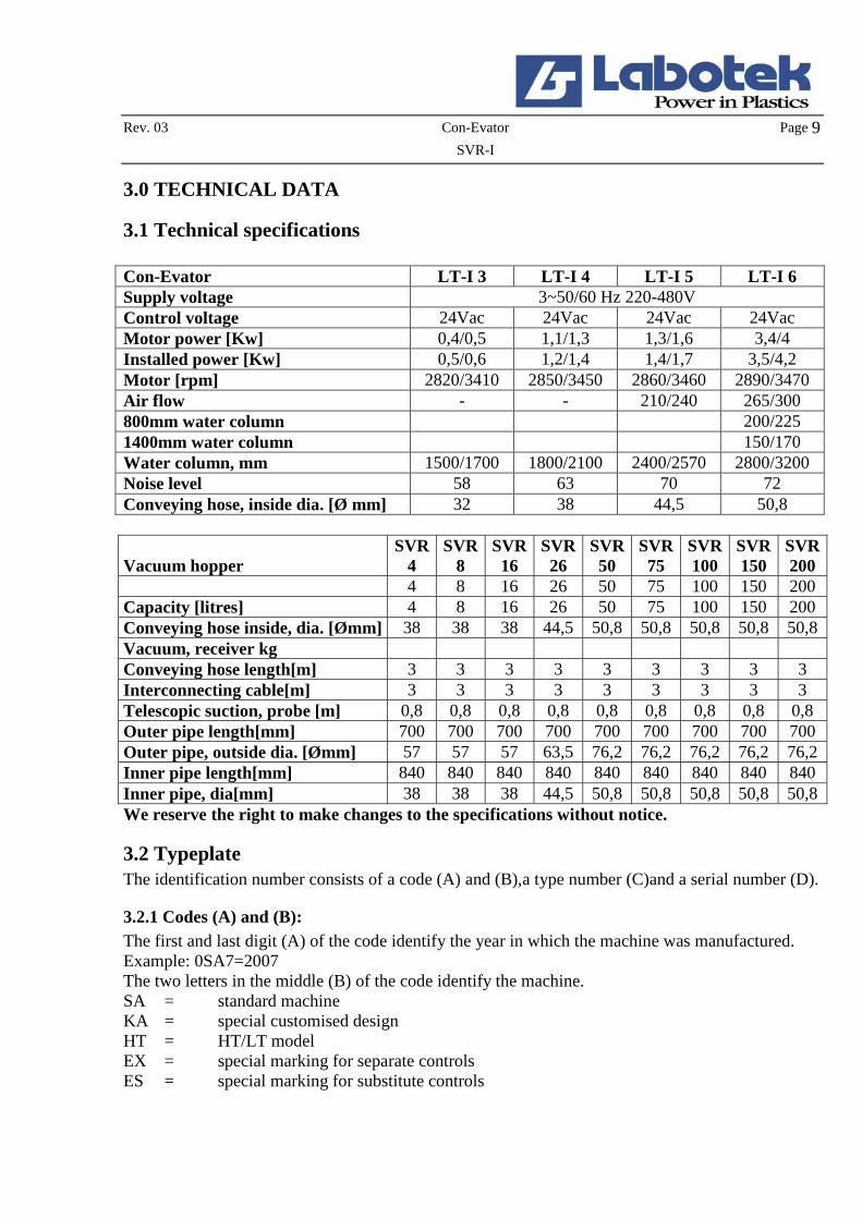
3.0 TECHNICAL DATA
3.1 Technical specifications Con-Evator LT-I 3 LT-I 4 LT-I 5 LT-I 6 Supply voltage 3~50/60 Hz 220-480V Control voltage 24Vac 24Vac 24Vac 24Vac Motor power [Kw] 0,4/0,5 1,1/1,3 1,3/1,6 3,4/4 Installed power [Kw] 0,5/0,6 1,2/1,4 1,4/1,7 3,5/4,2 Motor [rpm] 2820/3410 2850/3450 2860/3460 2890/3470 Air flow - - 210/240 265/300 800mm water column 200/225 1400mm water column 150/170 Water column, mm 1500/1700 1800/2100 2400/2570 2800/3200 Noise level 58 63 70 72 Conveying hose, inside dia. [Ø mm] 32 38 44,5 50,8
Vacuum hopper SVR
4 SVR
8 SVR
16 SVR
26 SVR
50 SVR
75 SVR100
SVR150
SVR200
4 8 16 26 50 75 100 150 200 Capacity [litres] 4 8 16 26 50 75 100 150 200 Conveying hose inside, dia. [Ømm] 38 38 38 44,5 50,8 50,8 50,8 50,8 50,8 Vacuum, receiver kg Conveying hose length[m] 3 3 3 3 3 3 3 3 3 Interconnecting cable[m] 3 3 3 3 3 3 3 3 3 Telescopic suction, probe [m] 0,8 0,8 0,8 0,8 0,8 0,8 0,8 0,8 0,8 Outer pipe length[mm] 700 700 700 700 700 700 700 700 700 Outer pipe, outside dia. [Ømm] 57 57 57 63,5 76,2 76,2 76,2 76,2 76,2 Inner pipe length[mm] 840 840 840 840 840 840 840 840 840 Inner pipe, dia[mm] 38 38 38 44,5 50,8 50,8 50,8 50,8 50,8 We reserve the right to make changes to the specifications without notice.
3.2 Typeplate The identification number consists of a code (A) and (B),a type number (C)and a serial number (D).
3.2.1 Codes (A) and (B): The first and last digit (A) of the code identify the year in which the machine was manufactured. Example: 0SA7=2007 The two letters in the middle (B) of the code identify the machine. SA = standard machine KA = special customised design HT = HT/LT model EX = special marking for separate controls ES = special marking for substitute controls

Rev. 03 Con-Evator Page 10
SVR-I
3.2.2 Type (C) The type number consists of two digits characterising the machine type: SVR4: 80 SVR75: 41 SVR8: 82 SVR100: 42 SVR16: 87 SVR150: 43 SVR26: 88 SVR200: 44 SVR50: 89
3.2.3 Serial number (D) The serial number is a five-digit number referring to the individual manufacturing number of the machine.
3.3 Dimensioned drawings All measurements are in mm.
R2384 R2371

Rev. 03 Con-Evator Page 11
SVR-I
3.4 Capacity table Con-Evator Horizontal
SVR 4 Blower 0.4 kW Capacity table
[kg/h]
1 3 6 12 18 24 30 36 42 48 54
kg/h Vertical 3 216 202 198 188 177 167 156 144 133 121 109 Conveying 4 206 189 180 169 158 147 138 129 120 112 103 Distance [m] 5 183 168 166 156 145 134 127 119 112 103 93 Con-Evator Horizontal
SVR 8 Blower 0.4 kW Capacity table
[kg/h] 1 3 6 12 18 24 30 36 42 48 54
kg/h Vertical 3 319 302 282 262 243 223 204 185 166 149 131 Conveying 4 298 189 247 228 209 190 176 161 147 134 121 Distance [m] 5 253 268 222 204 185 167 156 145 135 122 108 Con-Evator Horizontal
SVR 4 Blower 1,1 kW Capacity table
[kg/h] 1 3 6 12 18 24 30 36 42 48 54
kg/h Vertical 3 316 264 264 259 254 249 243 236 230 221 213 Conveying 4 306 256 256 252 248 244 238 233 227 218 209 Distance [m] 5 283 247 241 237 232 228 225 221 218 210 202 Con-Evator Horizontal
SVR 8 Blower 1,1 kW Capacity table
[kg/h]
1 3 6 12 18 24 30 36 42 48 54
kg/h Vertical 3 467 446 447 432 416 401 386 371 356 339 321 Conveying 4 436 417 410 405 399 394 379 363 348 326 305 Distance [m] 5 414 394 392 386 391 376 356 336 316 304 293

Rev. 03 Con-Evator Page 12
SVR-I
Con-Evator Horizontal
SVR 16 Blower 1,1 kW Capacity table
[kg/h] 1 3 6 12 18 24 30 36 42 48 54
kg/h Vertical 3 719 670 673 640 608 595 545 515 485 454 423 Conveying 4 650 608 593 582 571 560 503 501 471 434 396 Distance [m] 5 601 560 557 546 535 524 488 441 415 395 375 Con-Evator Horizontal
SVR 26 Blower 1,3 kW Capacity table
[kg/h] 1 3 6 12 18 24 30 36 42 48 54
kg/h Vertical 3 1071 980 945 929 913 897 867 838 808 750 691 Conveying 4 980 958 937 905 872 840 816 792 768 714 659 Distance [m] 5 931 868 848 825 799 774 760 746 732 668 603 Con-Evator Horizontal
SVR 50 Blower 3,4 kW Capacity table
[kg/h]
1 3 6 12 18 24 30 36 42 48 54
kg/h Vertical 3 1488 1352 1324 1282 1240 1198 1134 1071 1007 961 914 Conveying 4 1413 1339 1288 1242 1197 1151 1097 1044 990 934 878 Distance [m] 5 1340 1229 1167 1135 1104 1072 1028 983 939 883 826 Con-Evator Horizontal
SVR 50 Blower 3,4 kW with blow-back Capacity table
[kg/h]
1 3 6 12 18 24 30 36 42 48 54
kg/h Vertical 3 2053 1804 1454 1683 1611 1540 1439 1339 1238 1169 1100Conveying 4 1914 1781 1691 1615 1539 1463 1380 1296 1213 1130 1048Distance [m] 5 1782 1592 1489 1439 1388 1338 1271 1203 1136 1056 975 The above capacities kg/h at the respective distances set out in the table are based on the assumption that the vacuum hopper is completely filled during each conveying cycle. Over and above to the vertical and horizontal conveying distances, the available capacity depends on the characteristics of the pellet, size and bulk density. The specified capacities are based on a general bulk density of 0.6 kg/land the above capacity table states recommended values only.

Rev. 03 Con-Evator Page 13
SVR-I
3.6 Noise level Noise level dBA according to DS/ISO 3746 (without conveying): LT-I 3 /SVR 4-8 LT-I 4 /SVR 16 LT-I 5 /SVR 26 LT-I 6 /SVR 50 58 63 70 72

Rev. 03 Con-Evator Page 14
SVR-I
4.0 ASSEMBLY /DISASSEMBLY
4.1 Assembly
4.1.1 Assembly of standard SVR hopper loader with LT-I blower 1. Fit the LT-I blower (88) on a wall, a machine or on another stable object using the angle
bracket (5).For dimensions, see section 3.3 fig. 2. Remove the tape that secures the bottom flap during transportation. 3. Fit the SVR hopper directly on the lid of a machine hopper, a bin or a silo mouth-diameter Ø
200.Mount the hopper in the four assembly holes as shown in fig.R2029 section 4.0 Assembly.
4. Fit the conveying hose (2) on the inlet pipe (89) of the SVR hopper using the clip (90). 5. Fit the conveying hose (2) on the suction probe (14) using the clip (90). 6. Fit the vacuum hose (8) between the inlet branch (25) of the angle bracket and the lid (9) of
the hopper. 7. Fit the interconnecting cable between hopper (83) and control (1) using the plug connection
(87). 8. Connect the machine to the mains voltage. First check that the voltage available corresponds
to the voltage specified on the type plate of the unit. 9. If the LT-I blower has been supplied with a blow-back valve, the valve is to be connected to
pressure air supply 5-7 bar.
R2029 R2040
SVR 4 - 50 SVR 75 - 200
Rev. 03 Con-Evator Page 15
SVR-I
4.1.4 Assembly of Con-Evator with separate control 1. Fit hopper, suction probe and suction hose as described in section 4.1.1. 2. Fit the control at an appropriate location. 3. Wire following the diagram.
4.2 Disassembly 1. Turn off the machine on the main switch. 2. Remove plug/wire from the mains voltage. 3. Remove the bolts in the flange of the Con-Evator. 4. Disassemble the Con-Evator.
4.3 Electric connection 1. First, assemble the Con-Evator. See section 4.1. 2. Check that the voltage available corresponds to the voltage specified on the type plate of the
unit. See section 3.2. 3. Fit the unit on an intermediate hopper or another hopper. Connect to mains voltage. 4. Check that the phases of the Con-Evator have been connected in the proper sequence. Check
this during conveying and filter cleaning by comparing the direction of rotation the rotating indicator located on the fan hood. If the Con-Evator has been installed properly, air is discharged through the hose connection, when the blower starts shortly for filter clearing
4.4 Control The Con-Evator Control is designed for continuous operation of a vacuum blower 0.1kW - 3,4 kW, 380-480V AC for conveying of plastic material. The external inputs for the control are: Position of bottom flap in hopper loader External level control External capacitive sensor. The Con-Evator has 4 (four) basic standard conveying programs. P1: Conveying with filter cleaning (reverse) before conveying (old type M312)
Conveying of powder with filter cleaning with compressed air from compressed air container. P2: Conveying with filter cleaning (reverse) after conveying (old type M313) P3: Conveying with filter cleaning via return air valve (old type M314) P4: Conveying in closed system with slide valve (old type M316)

Rev. 03 Con-Evator Page 16
SVR-I
4.4.1 Programme Choice The Con-Evator is delivered from factory with Program P1 as standard The program is selected on the DIP-switches on the back of the control front plate, as follows: 1. Disconnect the conventional power to the Con-Evator. 2. Dismantle the front plate/cover from the control 3. Select on the DIP switches one of the following possibilities: P1 = P2 = P3 = P4 = 4. Mount the front plate/cover and connect the conventional power. 5. Turn on the Con-Evator. The display will for 2 seconds show which program is chosen. The
Con-Evator will then be operating in this program.
4.4.2 Programming The Con-Evator control is equipped with 4 operating bottoms and 2 bottoms with 2 functions.
= Access to Programme mode / one parameter step down
= Selected value one step up
= Selected value one step down
= Accept of value. Alarm lamp will flash 3 times = accept of new value
= Alarm reset 1. Priority = Start / Stop 2. Priority
= Out of Programme mode 1. Priority = Quick selection. 2. Priority

Rev. 03 Con-Evator Page 17
SVR-I
4.4.3 List of parameters Program P1 Interval Factory
settings Recommended sec. Recommended-sec
Powder conveying 1: Filter cleaning/reverse 2-10 3 3 10 2: Pause1 5-40 10 See 4.5.2 5 3: Conveying 5-360 30 Depend of process Depend of process 4: Ratio Selector 1 5-360 0 Depend of process Depend of process 5: Ratio-Selector 2 5,360 0 Depend of process Depend of process 6: Pipe cleaning 0-30 10 10 20 7: Pause 2 drain of material from loader.
5-40 10 See 4.5.2 5
Program P2 Interval Factory
settings Recommended sec.
1: Conveying 5-360 30 Depend of process 2: Ratio selector 1 5-360 0 Depend of process 3: Ratio selector 2 5-360 0 Depend of process 4: Pipe cleaning 0-30 10 10 5: Pause 1 5-40 10 See 4.5.2 6: Filter cleaning/reverse 2-10 3 3 7: Pause 2 drain of material 5-40 10 See 4.5.2 Program P3 Interval Factory
settings Recommended sec.
1: Filter cleaning/ Blow back valve
0-10 3 3
2: Conveying 5-360 30 Depend of process 3: Ratio selector 1 5-360 0 Depend of process 4: Ratio selector 2 5-360 0 Depend of process 5: Pipe cleaning 0-30 10 20 6: Pause 1 drain of material 5-40 10 3 7: Pause 2 filter cleaning 5-40 10 20 Program P4 Interval Factory
settings Recommended sec.
1: conveying valve open 5-180 30 Depend of process 2: conveying pipe cleaning valve closed
5-180 30 Depend of process
3: Pause 1 drain of material 5-40 10 10
4.4.4 Recommended settings Motor size LT-I 3/0.4kW LT-I 4/1.1kW LT-I 5/1.6kW LT-I 6/3.4kW Pause after filter cleaning 10 15 15 25 Pause after conveying 10 10 15 20

Rev. 03 Con-Evator Page 18
SVR-I
4.5 Operation During operation the display will show the actual value of the selected parameter. The function will at the time be shown with diode at the front panel During “Pause” the display will show “ S “ Indicates that the Con-Evator is turned off by pressing the Stand-By bottom “ OFF “ Indicates that the Con-Evator is stopped due to an external command “ H “ Indicates that the bottom flap is not closed and the Con-Evator is waiting on a new
transport cycles. “ L “ Indicates that the bottom flap is closed – hopper loader is empty. “ E “ Indicates that motor for blower has been turned off by thermal protection.

Rev. 03 Con-Evator Page 19
SVR-I
4.5.1 Special functions The Con-Evator control is equipped with the following features: Quick-function The Con-Evator control has a Quick function for setting the conveying time.
Before start of conveying press and hold the button The display will start blinking and the setting of the transport time will increase. When the hopper
loader is full (no flow of material) release the button. The setting indicated on the display is the new conveying time (Accept indicated by alarm lamp) Conveying alarm If the Con-Evator has been running 3 (Three) conveying cycles without additional material it will go into conveying alarm The number of conveying cycles before the conveying alarm is activated can be selected between 0 and 5
Press and
Press 2 x : Number of conveying cycles will be show non the display. Note: By “0“ the conveying alarm will not be activated.. The operating of the Con-Evator will continue during conveying alarm. The conveying will automatically be reset if the high level sensor has been activated. The conveying alarm can be reset by pushing the reset button. Factory settings The factory settings can be re-activated with the following procedure. 1: Turn off the Con Evator by the main switch
2: Press and hold + at the same time. 3: Turn on the machine and the factory settings has been reactivated for all 4 programs Note: Individual settings of the parameters can be necessary to obtain correct operation.

Rev. 03 Con-Evator Page 20
SVR-I
Wireless Remote Control For further user comfort Labotek has developed a wireless remote control which is able to identify and service up to 99 units. SVR-I It is strongly recommended to user different numbers for different Con-Evators. 1. Turn off the Con-Evator at the main switch
2. Press and hold 3. Turn on the machine at the main switch. A machine number is shown gradually increasing
from 01 to 99. 4. At the actual machine number release the button. The Com/alarm lamp blinks 3 times to
indicate accepts of number. Note: Machine number 00 can not be used. The following buttons at the control panel corresponds with the following buttons at the remote control.
=
=
=
=
=
= Communication via the remote control is done the following way:
1: Point the remote control at the Con-Evator control and press 2: The display in the control will show the ID number. 3: Press the ID number at the remote control The ID number will disappear from the display and the remote control is now in communication with the control of the Con-Evator and changes of parameters can be done. The communication between the remote control and the Con-Evator control will automatically be disconnected 30 sec after latest change of parameters. Program-Version 1: Turnoff the Con-Evator at the main switch
2. Press and hold 3. Turn on the Con-Evator at the main switch and the program version will be show non the
display for 2 seconds.

Rev. 03 Con-Evator Page 21
SVR-I
External Connections The Con-Evator can be controlled, on/off, by a non potential signal The following sensors can be connected to the control Button flap PGT Magnet switch SVR Rotating level control drying hopper DH / Material hopper Capacitive sensor Material hopper / Silo Ratio-Selector Pipe cleaning valve Slide valve Blow Back valve Alarm lamp Compressed air valve (filter cleaning)
4.5.2 Alarms The Con-Evator is equipped with the following alarms 1: » E » shown in the display indicates that motor is overheated and is disconnected by the
thermonal protection. The Con-Evator is totally disconnected and the alarm lamp is blinking. The temperature is measured by a clixon contact built in the motor. Terms for resetting: Motor cooled to temperature with in the specifications. Turn off and turn on the Con-Evator at the main switch.
2: “Transport alarm” By insufficient martial flow the transport alarm is activated (Com-lamp
and external alarm lamp (se 4.5.4) Terms for resetting: Sufficient material flow or press bottom 5.
R2382

Rev. 03 Con-Evator Page 22
SVR-I
4.5.3 Adjustment of the suction probe In order to achieve maximum and consistent conveying it is important that the suction probe has been adjusted correctly. 1. Press the suction probe down into the granules. 2. Loosen the finger screw (46) to release the suction probe (14) from the outer tube (16). 3. While the Con-Evator is conveying, adjust the suction probe and the outer tube to each other
until consistent and uniformed conveying has been established. 4. Tighten the finger screw (46) to secure the suction probe and the outer tube in the adjusted
position.
14
Fig. 4.5.3
46 16
R1193
4.5.4 Adjusting the bottom flap During normal operation the bottom flap should not be adjusted unless it fails. See section 6.3 and 6.6 Maintaining the bottom flap.
4.6 Start Turn the main switch to position 1. The machine will start after approx. 20 seconds. Before starting: see section 4.1 about machine settings, if required.
4.7 Operation 1. Once the Con-Evator has been started, operation is fully automatic (usually in batch processes
as the intermediate hopper will occasionally be full) as the bottom flap acts as level control starting and stopping the loading cycle.
2. To ensure maximum performance and life of the machine, proper maintenance should be strictly observed. See section 6.0 Maintenance.
4.8 Stop 1. Stop the Con-Evator by turning the main switch at the control to position 0, or push the
reset/stand-by button.
Rev. 03 Con-Evator Page 23
SVR-I
5.0 ACCESSORIES
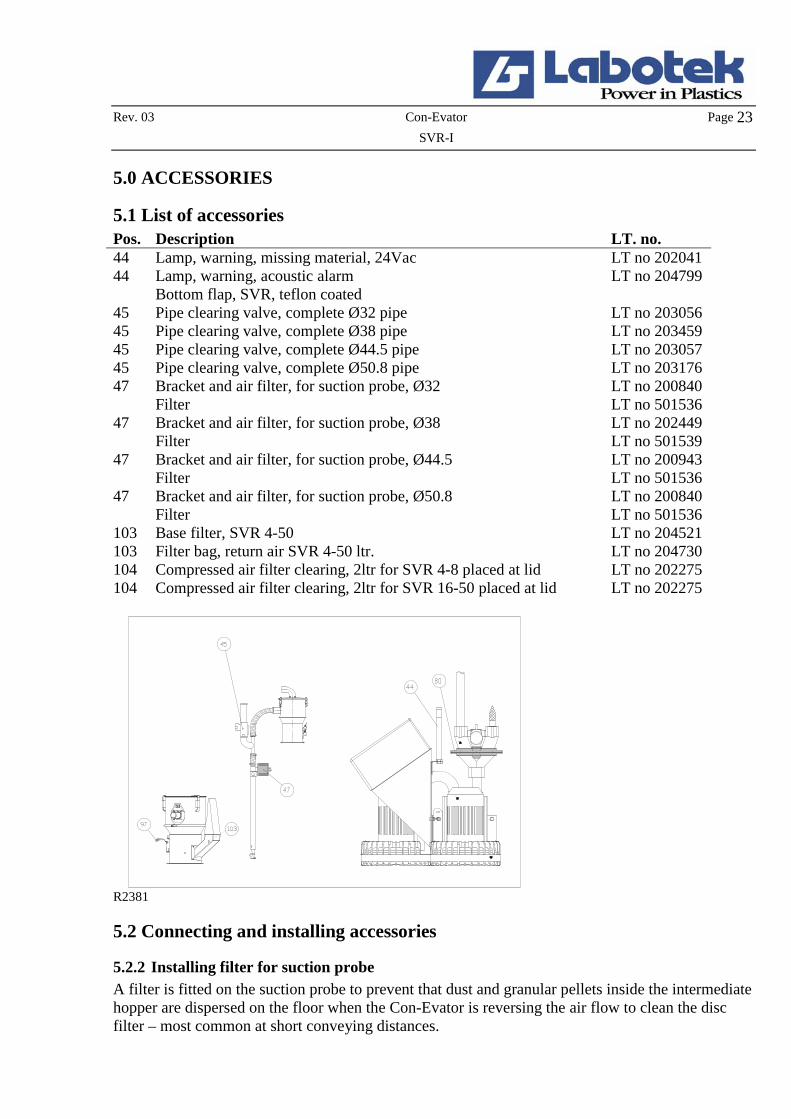
5.1 List of accessories Pos. Description LT. no. 44 Lamp, warning, missing material, 24Vac LT no 202041 44 Lamp, warning, acoustic alarm LT no 204799 Bottom flap, SVR, teflon coated 45 Pipe clearing valve, complete Ø32 pipe LT no 203056 45 Pipe clearing valve, complete Ø38 pipe LT no 203459 45 Pipe clearing valve, complete Ø44.5 pipe LT no 203057 45 Pipe clearing valve, complete Ø50.8 pipe LT no 203176 47 Bracket and air filter, for suction probe, Ø32 LT no 200840 Filter LT no 501536 47 Bracket and air filter, for suction probe, Ø38 LT no 202449 Filter LT no 501539 47 Bracket and air filter, for suction probe, Ø44.5 LT no 200943 Filter LT no 501536 47 Bracket and air filter, for suction probe, Ø50.8 LT no 200840 Filter LT no 501536 103 Base filter, SVR 4-50 LT no 204521 103 Filter bag, return air SVR 4-50 ltr. LT no 204730 104 Compressed air filter clearing, 2ltr for SVR 4-8 placed at lid LT no 202275 104 Compressed air filter clearing, 2ltr for SVR 16-50 placed at lid LT no 202275
R2381
5.2 Connecting and installing accessories
5.2.2 Installing filter for suction probe A filter is fitted on the suction probe to prevent that dust and granular pellets inside the intermediate hopper are dispersed on the floor when the Con-Evator is reversing the air flow to clean the disc filter – most common at short conveying distances.

Rev. 03 Con-Evator Page 24
SVR-I
1. Remove the conveying hose from the suction probe. 2. Press the filter holder (56) over the inner and outer tube (14) (16) of the suction hose. Check
that the O-ring (57) has been fitted correctly. 3. Fit the cartridge filter (58), the disc (59) and the star handle (60) on filter holder (56). 4. Fit the conveying hose on the inner tube (14)
R1196
5.2.3 Installing the line clearing valve It is recommended to install a line clearing valve at vertical lifts exceeding 3 metres for LT-I 3 and LT-I 5, and 5 metres for LT-I 6. The line clearing valve prevents material which is in the vertical conveying hose during conveying from falling back and becoming stuck in the hose when conveying stops. By the end of each conveying cycle the line clearing valve admits air into the conveying hose at the point just above the suction probe. The line clearing valve facilitates start of a new conveying cycle, as no mass of compact material is stuck in the pipes. 1. Fit the T-pipe (61) near by the suction probe (14). 2. Fit the conveying hose (2) on the T-pipe (61). 3. Fit the line clearing valve (45) on the T-pipe (61). 4. Connect compressed air supply 4-10 bar to the
connecting branch (62) of the line clearing valve. 5. Wire (63) between line clearing valve and control,
follow the diagram. OBS! For reason of weight the line clearing valve should be fitted at an appropriate location e.g. a wall. R1197

Rev. 03 Con-Evator Page 25
SVR-I
5.2.7 Installing the Teflon-coated bottom flap A Teflon-coated bottom flap is used where the conveyed material has a tendency to stick to the bottom flap, due for instance to static electricity. Granular pellets stuck to the bottom flap may impede the full closure of the bottom flap, thus causing the hopper to leak at the bottom and preventing the generation of vacuum. 1. Turn off the machine by turning the power switch to position 0. 2. Disconnect the mains voltage. 3. Dismount the Con-Evator from the processing machine. 4. Turn the machine upside down or sideways and dismount the bottom flap by removing the
screw and the disc (66). 5. Clean of dust and soil from the assembly roller (67). 6. Fit the Teflon-coated bottom flap (51) on the assembly roll (67), the Teflon-coated side facing
the outlet branch. To adjust the bottom flap dislocate the flap in the longish hole until the outlet branch is fully covered.
R1201 7. Adjust the spring function of the bottom flap, if required. See section 6.3.1. 8. Install the Con-Evator on the processing machine and connect to mains voltage.

Rev. 03 Con-Evator Page 26
SVR-I
5.2.8 Fitting the alarm lamp 1. Turn the main switch to position 0 and unplug blower. 2. Remove the front cover of the control (35). 3. Remove blind plugs (68) from the top face of the control. 4A. Fit alarm lamp (44) on the bracket in the free assembly holes. 4B. Fit alarm lamp (44) on the top face of the
control in the free assembly holes. 4C. Fit alarm lamp (44) on the bracket in the free assembly holes. 5. Wire in the control follow the diagram. 6. Fit the front cover (35).
R2379

Rev. 03 Con-Evator Page 27
SVR-I
6.0 MAINTENANCE - SVR The filter should be checked and cleaned at least once a week. A worn filter must been replaced.
6.1 Maintaining the air filter and the base filter Note! The air filter and the base filter should be checked at every 24 hours of operation as a minimum.
6.1.1 Air filter 1. Turn off the machine on the power switch. Open the lid on the SVR hopper loader. 2. Remove the filter (93) and the filter bag by loosening the fly nut (92). 3. Pull the filter bag over the air filter. 4. Shake to have the dust bag cleared. Clean using compressed air, if necessary 5. Clean the air filter using compressed air, and check that the filter is in working order. 6. Clean the filter surfaces. 7. Replace the filter bag over the filter and fasten the filter. 8. Close the lid.
6.1.2 Base filter 1. Turn off the machine on the power switch. Open the snap lock (94). 2. Remove the fine base filter (95) from the base filter (96). Clean using compressed air and
check that the filter is in working order. 3. Insert the filter mesh and close the snap lock (94).
R2043 R2042

Rev. 03 Con-Evator Page 28
SVR-I
6.2 Maintaining the bottom flap SVR (stainless steel) The function of the bottom flap should be checked once a month. A damaged or bent bottom flap must be replaced. 1. Remove the base filter. 2. Check visually whether the bottom flap is intact. 3. Verify that the bottom flap can move freely. 4. Check that the gap between the discharge branch and the bottom flap is approx. 10-30 mm
when the bottom flap hangs loose. 5. Replace the filter (96).
6.3 Adjustment of the magnetic switch 1. Clear the intermediate hopper 2. Turn off the machine by turning the power switch to position 0. 3. Remove the filter (96). 4. Remove plug and fit test lamp (97) (optional). 5. The test lamp (97) is to lit up when the bottom flap hangs lose or has been closed. When the
bottom flap is fully open, the test lamp must turn off. 6. Adjust the activation point by adjusting the two screws that hold the fixture for the magnetic
switch (100). The fixture is adjusted up-and-down so that the magnetic switch (99) is moved to-and-fro the magnet (98).
7. When the activation point has been adjusted, tighten the screws and replace the filter (96)
10- 30mm
R2045 R2044

Rev. 03 Con-Evator Page 29
SVR-I
7.0 TROUBLESHOOTING
7.1 The Con-Evator does not start Has the Con-Evator been connected properly to the mains voltage?
No Connect properly
Yes Is the power switch turned to position 1? No Turn the power switch to position 1. Yes Are the control fuses in working order? No Replace fuse. Yes Has the overload protection disconnected the control voltage?
No Press the reset button at the overload protection.
No Has the bottom flap been properly adjusted? See section 6.3.1 and 6.3.2.
No Adjust the bottom flap. See section 6.3.1 and 6.3.2
7.2 The Con-Evator capacity has been reduced Is the disc filter clean and unclogged? No Clean or replace the filter. Yes Has the suction probe been adjusted correctly?
No Adjust the suction probe correctly. See section 4.5.3.
Yes Has the conveying time been adjusted correctly (setting of conveying time with reference to conveying distance)
No Adjust the conveying time. See section 4.5.1.
Yes Is the phase sequence correct? Replace phase, if necessary.
No Check according to section 4.3.
Yes
Does the blow-back valve change position? No Check: Compressed air connection, air filter on solenoid valve, connection of solenoid valve.
7.3 The Con-Evator stops at short intervals Because the overload protection has been activated.
Is the disc filter cleaned and unclogged? No Clean or replace the disc filter. See section 6.1
Yes Have the settings on the overload protection been adjusted correctly?
No Check settings. Adjust according to diagram, if necessary.
Yes Does the machine start at short intervals?
No Increase conveying time. See section 4.5.1.

Rev. 03 Con-Evator Page 30
SVR-I
8.0 REPAIRS
8.1 Replacement of fuse for control voltage 1. Turn the main switch (28) to position 0 and unplug blower. 2. Remove the front cover (35) of the control to allow access to the fuses:
(31A) Primary voltage (31B) Secondary voltage
3. Grab the small flap on the fuse and pull it outwards 4. Insert new fuse (31) by pushing it firmly in place. 6. Replace the front cover (35) on the control and connect the machine.
R2383
8.2 Replacement of bottom flap SVR (stainless steel) 1. Clear the vacuum hopper loader. 2. Disconnect the machine by turning the power switch to position 0. 3. Disconnect the mains voltage. 4. Dismount the vacuum hopper loader from the processing machine. 5. Turn the hopper upside down or sideways. Remove the bottom flap by removing the split pin
(101). 6. Remove the magnet (98) and the balance weight (102) at the bottom flap. 7. Fit the magnet (98) and the balance weight (102) on a new bottom flap. 8. Clear dust and soil from the fixture. 9. Fit the bottom flap in the fixture using the split pin (101). 10. Adjust the magnetic switch as described in section 6.8. 11. Replace the vacuum hopper loader on the processing machine and connect mains voltage.
R2046