manual ethernetip en - indstore · manual_ethernetip_en.doc 2/51 ... explicit messaging, plc...
TRANSCRIPT

02.12 · 174.02.060/6 Subject to modification in technic and design. www.baumer.com Errors and omissions excepted.
Manual Absolute Encoder with EtherNet/IP (with bus cover) Firmware Version 1.01 and up

Manual_EtherNetIP_EN.doc 2/51 www.baumer.com 13.02.12
Content Page 1. Introduction 4 1.1. Scope of delivery 4 1.2. Product allocation 4 2. Safety precautions and operating instructions 5 3. Product family 6 4. Device profile 7 4.1. Introduction 7 4.2. Object model 8 4.3. Identity Object – 01hex 9 4.4. Position Sensor Object – 23hex 12 4.5. Assembly Object – 04hex 17 4.6. Assembly Instances 18 4.7. Parameter Object – 0Fhex 20 5. EtherNet/IP-specific objects 24 5.1. Introduction 24 5.2. Ethernet Link Object – F6hex 24 5.3. TCP/IP Interface Object – F5hex 24 6. Commissioning 24 6.1. Mechanical mounting 24 6.2. Electrical connection 24 6.2.1. Cabling 24 6.2.2. Connecting the bus cover 24 6.3. Operating display (multi-colour LED) 24 6.4. Activity display (green LEDs) 24 7. IP address allocation 24 7.1. EtherNet/IP bus cover with HEX rotary switches: IP-assignment after Power On 24 7.2. Allocate IP address with BOOTP/DHCP configuration tool 24 7.3. RSLinx Classic Lite 24 7.4. RSWho 24 8. Device configuration 24 8.1. Introduction 24 8.2. Using the parameter object 24 8.3. Application of the configuration assembly instance 105 24 8.4. Direct application of the position sensor object 24 9. RSLogix5000 project example 24 9.1. Reading in the input data 24 9.1.1. Configure Generic Ethernet Module 24 9.2. Explicit Messaging, PLC Program Example, Set Preset 24 9.2.1. Create program tags 24 9.2.2. Create Controller Tags 24 9.2.3. Configuration of the message tag 24 10. Used abbreviations and terms 24 11. FAQ‘s 24 11.1. Device not responding / IP address unknown 24

Manual_EtherNetIP_EN.doc 3/51 www.baumer.com 13.02.12
Disclaimer of liability The present manual was compiled with utmost care, errors and omissions reserved. For this reason Baumer rejects any liability for the information compiled in the present manual. Baumer nor the author will accept any liability for direct or indirect damages resulting from the use of the present information. At any time we should be pleased receiving your comments and proposals for further enhancement of the present manual. Created by: Baumer IVO GmbH & Co. KG Villingen-Schwenningen, Germany Registered Trademarks RSLinxTM , RSNetWorxTM und RSLogix5000TM are registered trademarks of Rockwell Automation. The EtherNet/IP Logo is a registered trademark of ODVA, Inc. This and other trademarks referred to in the present manual which at the same time might be registered trademarks bear no corresponding mark. Having omitted the respective mark does not necessarily implicate the conclusion of a free brand name, nor does it refer to any existing patents and protected patented designs.
Manual_EtherNetIP_EN.doc 4/51 www.baumer.com 13.02.12
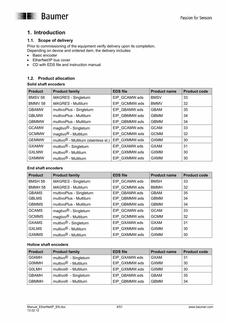
1. Introduction 1.1. Scope of delivery Prior to commissioning of the equipment verify delivery upon its completion. Depending on device and ordered item, the delivery includes: • Basic encoder • EtherNet/IP bus cover • CD with EDS file and instruction manual 1.2. Product allocation Solid shaft encoders
Product Product family EDS file Product name Product code BMSV 58 MAGRES - Singleturn EIP_GCAMW.eds BMSV 33 BMMV 58 MAGRES - Multiturn EIP_GCMMW.eds BMMV 32 GBAMW multivoPlus - Singleturn EIP_GBAMW.eds GBAM 35 GBLMW multivoPlus - Multiturn EIP_GBMMW.eds GBMM 34 GBMMW multivoPlus - Multiturn EIP_GBMMW.eds GBMM 34 GCAMW magtivo® - Singleturn EIP_GCAMW.eds GCAM 33 GCMMW magtivo® - Multiturn EIP_GCMMW.eds GCMM 32 GEMMW multivo® - Multiturn (stainless st.) EIP_GXMMW.eds GXMM 30 GXAMW multivo® - Singleturn EIP_GXAMW.eds GXAM 31 GXLMW multivo® - Multiturn EIP_GXMMW.eds GXMM 30 GXMMW multivo® - Multiturn EIP_GXMMW.eds GXMM 30
End shaft encoders
Product Product family EDS file Product name Product code BMSH 58 MAGRES - Singleturn EIP_GCAMW.eds BMSH 33 BMMH 58 MAGRES - Multiturn EIP_GCMMW.eds BMMH 32 GBAMS multivoPlus - Singleturn EIP_GBAMW.eds GBAM 35 GBLMS multivoPlus - Multiturn EIP_GBMMW.eds GBMM 34 GBMMS multivoPlus - Multiturn EIP_GBMMW.eds GBMM 34 GCAMS magtivo® - Singleturn EIP_GCAMW.eds GCAM 33 GCMMS magtivo® - Multiturn EIP_GCMMW.eds GCMM 32 GXAMS multivo® - Singleturn EIP_GXAMW.eds GXAM 31 GXLMS multivo® - Multiturn EIP_GXMMW.eds GXMM 30 GXMMS multivo® - Multiturn EIP_GXMMW.eds GXMM 30
Hollow shaft encoders
Product Product family EDS file Product name Product code G0AMH multivo® - Singleturn EIP_GXAMW.eds GXAM 31 G0MMH multivo® - Multiturn EIP_GXMMW.eds GXMM 30 G0LMH multivo® - Multiturn EIP_GXMMW.eds GXMM 30 GBAMH multivo® - Singleturn EIP_GBAMW.eds GBAM 35 GBMMH multivo® - Multiturn EIP_GBMMW.eds GBMM 34

Manual_EtherNetIP_EN.doc 5/51 www.baumer.com 13.02.12
2. Safety precautions and operating instructions Supplementary information • The present manual is intended as a supplement to already existing documentation (catalogues, product
data sheets and mounting instructions). • The manual must be studied carefully prior to initial commissioning of the equipment. Intended purpose of the equipment • The encoder is a precision sensing device. It is utilized to determine angular positions and revolutions,
and to prepare and supply measured values in the form of electrical output signals for the downstream device. Encoders must not be used for any other purpose.
Commissioning • The encoder must be initialised and mounted only by a qualified expert. • Observe the operating instructions of the machine manufacturer. Safety instructions • Check all electrical connections prior to commissioning of the equipment. • If mounting, electrical connections or any other work performed at the encoder and the equipment is not
correctly executed this can result in malfunction or failure of the encoder. • Corresponding safety precautions must be provided and observed to exclude any risk of personal injury,
damage to material or operating equipment as a result of encoder failure or malfunction. • The encoder must not be operated beyond the limits (see supplementary documentation). Failure to observe these safety instructions can result in malfunctions, material damage or personal injury. Transport and storing • Only ever transport or store the encoder in its original packaging. • Never drop the encoder nor expose it to major shocks. Mounting • Avoid impacts or shocks on housing and shaft/hollow shaft. • Avoid any twist or torsion on the housing. • Never provide rigid connections between encoder shaft and drive shaft. • Do not open the encoder or carry out any mechanical modifications. Shaft, ball bearings, glass disc or electronic components can be damaged thereby and a safe and reliable operation is no longer ensured. Electrical commissioning • Do not carry out any electrical modifications at the encoder. • Do not carry out any wiring work while encoder is live. • Never plug or unplug connector while encoder is live (the bus cover however may be removed or docked
to the basic encoder when live). • Ensure that the entire system is installed in line with EMC/EMI requirements. Operating environment and
wiring have an impact on the electromagnetic compatibility of the encoder. Install encoder and supply cables separately or far away from sources with high emitted interference (frequency converters, contactors, etc).
• When working with consumers with high emitted interference provide separate encoder supply voltage. • Completely shield encoder housing and connecting cables.. • Connect encoder to protective earth (PE) using shielded cables. The braided shield must be connected
to the cable gland or connector. Ideally, aim at dual connection to protective earth (PE), i.e. housing by mechanical assembly and cable shield by the downstream devices. In case of earth loop problems, earth at least on one side.
Failure to observe these instructions can result in malfunctions, material damage or personal injury!!

Manual_EtherNetIP_EN.doc 6/51 www.baumer.com 13.02.12
3. Product family The product family architecture is modular. Depending on what is required from the encoder, the basic encoder and bus covers can be combined at will with the selected bus system. The basic encoders differ in terms of accuracy, ambient conditions and the utilized sensing principle. Bus cover The bus cover accommodates the field bus interface and the complete electronics for processing the measured values. EtherNet/IP communication is performed via the specialized EtherNet/IP-ASIC ERTEC200 with integrated high-performance microcontroller ARM9. Basic encoders Magres / magtivo® provides a 12 bit resolution with 4096 measuring units/turn, utilizes a magnetic sensing principle and endures harsh industrial environments. Procoder / multivo® provides a 13 bit resolution with 8192 measuring units/turn, utilizes a photoelectric/magnetic sensing principle and is the recommended product for standard applications. Dignalizer / activo® / multivoPlus® provides a 18 bit resolution with 262144 measuring units/turn, utilizes a photoelectric or photoelectric/magnetic sensing principle with integrated analog/digital signal conversion and is the product to chose for ultra-precise sensing applications. The bus covers differ by the respectively integrated bus interface. Available bus interfaces: CANopen, DeviceNet, EtherCAT, Ethernet/IP, LIGHTBUS (fiber-optic), Profibus-DP, Profinet, Powerlink, Power over EtherCAT, SAE J1939, SSI. Except for encoders with fiber-optic interface, all encoders enable parameterization by bus interface. Functional principle:
SAE J1939
bus cover complete encoderbasic encoder
Manual_EtherNetIP_EN.doc 7/51 www.baumer.com 13.02.12
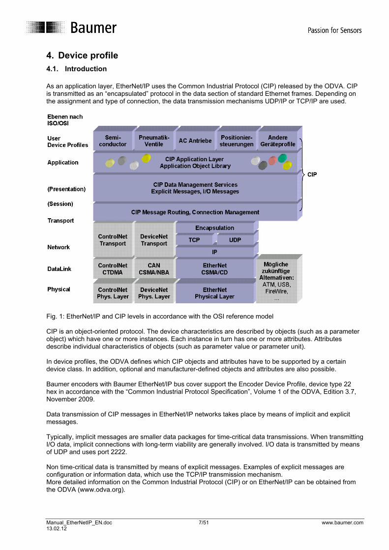
4. Device profile 4.1. Introduction As an application layer, EtherNet/IP uses the Common Industrial Protocol (CIP) released by the ODVA. CIP is transmitted as an “encapsulated” protocol in the data section of standard Ethernet frames. Depending on the assignment and type of connection, the data transmission mechanisms UDP/IP or TCP/IP are used.
Fig. 1: EtherNet/IP and CIP levels in accordance with the OSI reference model CIP is an object-oriented protocol. The device characteristics are described by objects (such as a parameter object) which have one or more instances. Each instance in turn has one or more attributes. Attributes describe individual characteristics of objects (such as parameter value or parameter unit). In device profiles, the ODVA defines which CIP objects and attributes have to be supported by a certain device class. In addition, optional and manufacturer-defined objects and attributes are also possible. Baumer encoders with Baumer EtherNet/IP bus cover support the Encoder Device Profile, device type 22 hex in accordance with the “Common Industrial Protocol Specification”, Volume 1 of the ODVA, Edition 3.7, November 2009. Data transmission of CIP messages in EtherNet/IP networks takes place by means of implicit and explicit messages. Typically, implicit messages are smaller data packages for time-critical data transmissions. When transmitting I/O data, implicit connections with long-term viability are generally involved. I/O data is transmitted by means of UDP and uses port 2222. Non time-critical data is transmitted by means of explicit messages. Examples of explicit messages are configuration or information data, which use the TCP/IP transmission mechanism. More detailed information on the Common Industrial Protocol (CIP) or on EtherNet/IP can be obtained from the ODVA (www.odva.org).
Manual_EtherNetIP_EN.doc 8/51 www.baumer.com 13.02.12
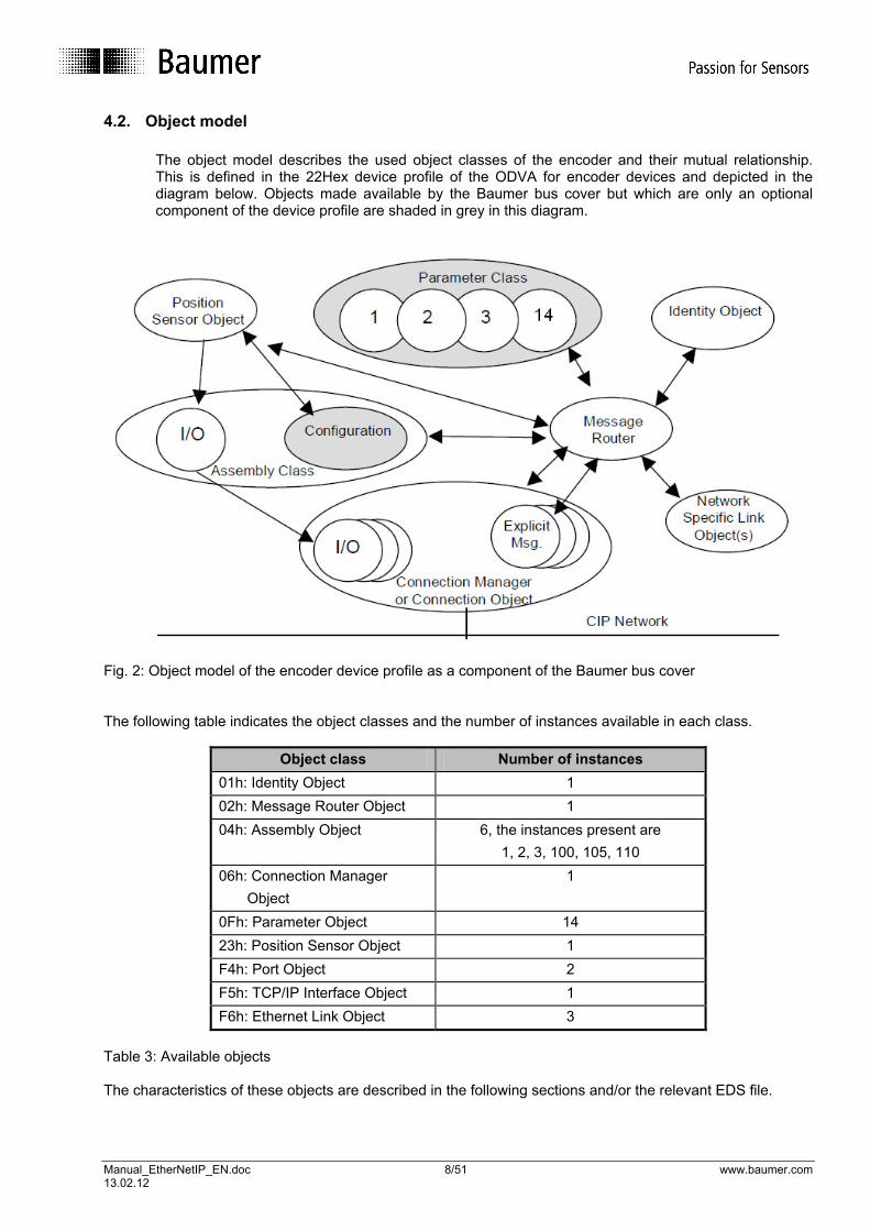
4.2. Object model
The object model describes the used object classes of the encoder and their mutual relationship. This is defined in the 22Hex device profile of the ODVA for encoder devices and depicted in the diagram below. Objects made available by the Baumer bus cover but which are only an optional component of the device profile are shaded in grey in this diagram.
Fig. 2: Object model of the encoder device profile as a component of the Baumer bus cover The following table indicates the object classes and the number of instances available in each class.
Object class Number of instances 01h: Identity Object 1 02h: Message Router Object 1 04h: Assembly Object 6, the instances present are
1, 2, 3, 100, 105, 110 06h: Connection Manager Object
1
0Fh: Parameter Object 14 23h: Position Sensor Object 1 F4h: Port Object 2 F5h: TCP/IP Interface Object 1 F6h: Ethernet Link Object 3
Table 3: Available objects The characteristics of these objects are described in the following sections and/or the relevant EDS file.
Manual_EtherNetIP_EN.doc 9/51 www.baumer.com 13.02.12
4.3. Identity Object – 01hex The identity object is implemented in accordance with the Common Industrial Protocol Specification. The object revision is 1, and the class code is 01h. Table 4 lists the available class attributes. Class attributes are addressed via instance 0. For the class attributes of the identity object, the services - 01h Get Attribute all - 0Eh Get Attribute single are supported. Attribute ID
Access Name Data type Description Values
1 read Revision UINT Object revision 1 2 read Max Instance UINT Highest instance number
existing in this class 1
3 read Number of Instances
UINT Number of existing instances
1
Optional attribute list
STRUCT of List of supported optional instance attributes
number of attributes UINT Number of supported optional instance attributes
2
4 read
optional attributes ARRAY of UINT
Number of optional instance attribute numbers
11, 12
6 read Maximum ID Number Class Attributes
UINT Attribute number of last class attribute
7
7 read Maximum ID Number Instance Attributes
UINT Attribute number of last instance attribute
12
Table 4: Class attributes of the identity object

Manual_EtherNetIP_EN.doc 10/51 www.baumer.com 13.02.12
The table below contains all supported instance attributes of the identity object. Attribute ID
Access Name Data type Description Values
1 read Vendor ID UINT Manufacturer identification 468 = Baumer IVO Vendor ID
2 read Device Type UINT Product type identification (device profile)
34 = 22hex
3 read Product Code UINT Identification of a manufacturer’s part product
Revision STRUCT of Product revision Major Revision USINT
4 read
Minor Revision USINT 5 read Status WORD Summarized device status
(see description below the table)
6 read Serial Number UDINT Device serial number 7 read Product Name SHORT_ST
RING Readable product identification
STRUCT of Language currently supported by the device
USINT Field 1 of STRINGI type USINT Field 2 of STRINGI type
11 read / write
Active Language
USINT Field 3 of STRINGI type
Based on ISO 639-2/T) STRINGI Data type
ARRAY of STRUCT of
List of supported languages as field of individual elements as described in attribute 11
USINT Field 1 of STRINGI type USINT Field 2 of STRINGI type
12 read Supported Language List
USINT Field 3 of STRINGI type
Table 5: Identity object, instance attributes
Manual_EtherNetIP_EN.doc 11/51 www.baumer.com 13.02.12
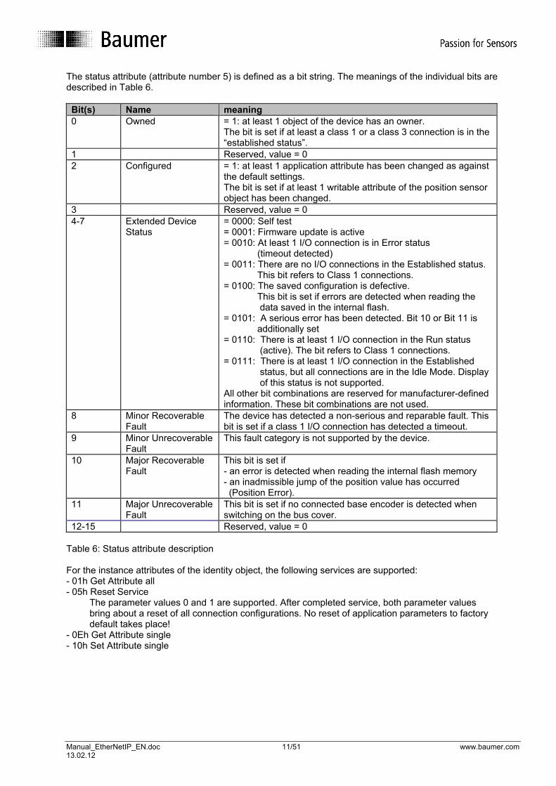
The status attribute (attribute number 5) is defined as a bit string. The meanings of the individual bits are described in Table 6. Bit(s) Name meaning 0 Owned = 1: at least 1 object of the device has an owner.
The bit is set if at least a class 1 or a class 3 connection is in the “established status”.
1 Reserved, value = 0 2 Configured = 1: at least 1 application attribute has been changed as against
the default settings. The bit is set if at least 1 writable attribute of the position sensor object has been changed.
3 Reserved, value = 0 4-7 Extended Device
Status = 0000: Self test = 0001: Firmware update is active = 0010: At least 1 I/O connection is in Error status (timeout detected) = 0011: There are no I/O connections in the Established status. This bit refers to Class 1 connections. = 0100: The saved configuration is defective. This bit is set if errors are detected when reading the data saved in the internal flash. = 0101: A serious error has been detected. Bit 10 or Bit 11 is additionally set = 0110: There is at least 1 I/O connection in the Run status (active). The bit refers to Class 1 connections. = 0111: There is at least 1 I/O connection in the Established status, but all connections are in the Idle Mode. Display of this status is not supported. All other bit combinations are reserved for manufacturer-defined information. These bit combinations are not used.
8 Minor Recoverable Fault
The device has detected a non-serious and reparable fault. This bit is set if a class 1 I/O connection has detected a timeout.
9 Minor Unrecoverable Fault
This fault category is not supported by the device.
10 Major Recoverable Fault
This bit is set if - an error is detected when reading the internal flash memory - an inadmissible jump of the position value has occurred (Position Error).
11 Major Unrecoverable Fault
This bit is set if no connected base encoder is detected when switching on the bus cover.
12-15 Reserved, value = 0 Table 6: Status attribute description For the instance attributes of the identity object, the following services are supported: - 01h Get Attribute all - 05h Reset Service The parameter values 0 and 1 are supported. After completed service, both parameter values bring about a reset of all connection configurations. No reset of application parameters to factory default takes place! - 0Eh Get Attribute single - 10h Set Attribute single
Manual_EtherNetIP_EN.doc 12/51 www.baumer.com 13.02.12
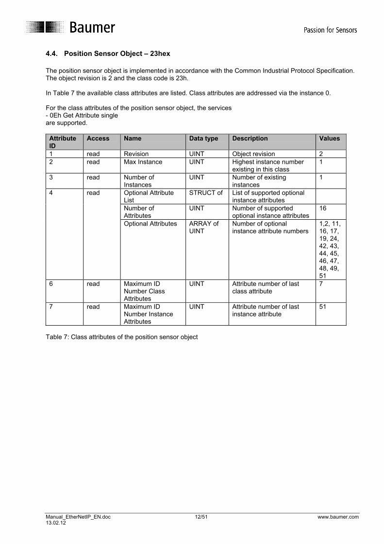
4.4. Position Sensor Object – 23hex The position sensor object is implemented in accordance with the Common Industrial Protocol Specification. The object revision is 2 and the class code is 23h. In Table 7 the available class attributes are listed. Class attributes are addressed via the instance 0. For the class attributes of the position sensor object, the services - 0Eh Get Attribute single are supported. Attribute ID
Access Name Data type Description Values
1 read Revision UINT Object revision 2 2 read Max Instance UINT Highest instance number
existing in this class 1
3 read Number of Instances
UINT Number of existing instances
1
Optional Attribute List
STRUCT of List of supported optional instance attributes
Number of Attributes
UINT Number of supported optional instance attributes
16
4 read
Optional Attributes ARRAY of UINT
Number of optional instance attribute numbers
1,2, 11, 16, 17, 19, 24, 42, 43, 44, 45, 46, 47, 48, 49, 51
6 read Maximum ID Number Class Attributes
UINT Attribute number of last class attribute
7
7 read Maximum ID Number Instance Attributes
UINT Attribute number of last instance attribute
51
Table 7: Class attributes of the position sensor object

Manual_EtherNetIP_EN.doc 13/51 www.baumer.com 13.02.12
The following table contains all supported instance attributes of the position sensor object. For a detailed description of individual instance attributes, see the table. Attribute ID
Access Name Data type
Description Values
1 read Number of Attributes
USINT Number of supported attributes
18
2 read Attribute List Array of USINT
List of supported attributes 1,2, 10, 11, 12, 16, 17, 19, 24, 42, 43, 44, 45, 46, 47, 48, 49, 51
10 read Position Value Signed
DINT Current position value
11 read Position Sensor Type
UINT Specifies the sensor type
12 read / write
Direction Counting Toggle
BOOL Defines the sense of rotation in which the position value rises.
CW = 0 CCW = 1
16 read/ write
Measuring Units per Span
UDINT Number of required measuring units per revolution
17 read/ write
Total Measuring Range in Measuring Units
UDINT Number of required measuring units over the entire measuring range
19 read / write
Preset Value DINT Position value is set to the reset value
24 read Velocity Value DINT Current speed value 42 read Physical Resolution
Span UDINT Number of maximum
distinguishable measuring units per revolution
43 read Number of Spans UINT Maximum number of revolutions
44 read Alarms WORD Indicates a detected error which can result in an incorrect position value or requires user intervention
45 read Supported Alarms WORD Information on supported alarms
46 read Alarm Flag BOOL Indicates whether an alarm has occurred.
47 read Warnings WORD Indicates any existing warnings
48 read Supported Warnings
WORD Information about supported warnings
49 read Warning Flag BOOL Indicates if a warning is active
51 read Offset Value DINT The offset is calculated with the preset function. The actually measured position is displaced by this value.
Table 8: Position sensor object, instance attributes
Manual_EtherNetIP_EN.doc 14/51 www.baumer.com 13.02.12
Position Value Signed – attribute 10 Absolute position of the sensor. Zero correction of the preset function is taken into consideration in the displayed value. The unit of measurement for the position value is increments or scanning steps or counts. Position Sensor Type – attribute 11 Depending on the used base encoder, one of the following values is displayed: 01 – Singleturn absolute encoder 02 – Multiturn absolute encoder Direction Counting Toggle – attribute 12 Behaviour of the position data depending on the sense of rotation of the encoder when rotating the encoder shaft seen looking at the flange. Setting CW (clockwise) = rising values when rotating clockwise Setting CCW (counterclockwise) = rising values when rotating counterclockwise The parameter value is saved in a non-volatile memory in case of changes. Measuring Units per Span – attribute 16 The attribute defines the number of distinguishable steps per revolution of the sensor. The value is an indication of the required single turn resolution (“measuring units per revolution“). Values between 1 and the maximum resolution of the encoder per revolution (attribute 42) are admissible. Reparameterization can result in a change of attribute 17 to the value of the equations (1) or (2), if the value of attribute 17 is smaller than the minimum value or greater than the maximum value. Reparameterization deletes the previous offset value (attribute 51), so that the previous position reference is lost. The parameter value is saved in a non-volatile memory in the event of a change. Total Measuring Range in Measuring Units – attribute 17 This attribute defines the total number of distinguishable steps over the entire measurement range. The minimum setting value is calculated as: Minimum value attr.. 17 = Set value attr. 16 (1) The maximum setting value is calculated as: Maximum value attr. 17 = Set value attr. 16 x value attr. 43 (2) If the number of revolutions is programmed to a value unequal to 2n (1, 2, 4, - 65536) then after traversing the sensor zero in a de-energized status, reparameterization must be carried out. The number of counted revolutions is calculated as: Number of counted revolutions = Set value attr. 17 ÷ Set value attr. 16 (3) Reparameterization deletes the previous offset value (attribute 51), so that the previous position reference is lost. The parameter value is stored in a non-volatile memory in the event of a change. Preset value – attribute 19 Offset value – attribute 51 The preset function supports adjustment of the encoder zero at the mechanical zero point of the system. In the event of a “set attribute” at attribute 19, the current position of the encoder is set to the preset value. The internal offset value (attribute 51) is calculated and stored in the encoder. The following rule applies: Preset value (attribute 19) = position value (attribute 10) + offset value (attribute 51) (4) Note: The preset function should only be used when the encoder is at a standstill. A preset must always be carried out after the following attributes have been changed:
• Measuring units per span – attribute 16, • Total measuring range in measuring units – attribute 17
When carrying out the preset function, an offset value (attribute 51) is internally calculated and stored as a non-volatile value in the flash memory, ensuring that the encoder retains the same unchanged position after switching off and back on. The flash memory is typically rewritable 100,000 times. However, despite the high number of possible write cycles, frequent program or event-controlled setting of the preset could foreshorten

Manual_EtherNetIP_EN.doc 15/51 www.baumer.com 13.02.12
the service life. When configuring the control software, a certain amount of care is consequently called for here. The preset can be selected in a range between zero and a value smaller than the set overall measurement range (attribute 17). Velocity Value – attribute 24 The current velocity value of the encoder. The velocity value is read out in the unit “counted scanning steps / second”. Physical Resolution Span – attribute 42 Using this attribute, the physical resolution of the encoder can be read out in the form of scanning steps per revolution. Number of Spans – attribute 43 Maximum number of distinguishable revolutions. The physical measurement range is made up of: Physical measurement range = attribute 42 (Physical Resolution Span) x attribute 43 (Number of Spans) (5) Alarms – attribute 44 Supported Alarms – attribute 45 Alarm Flag – attribute 46 Attribute 44 delivers alarm messages. An alarm is set if the encoder has detected a status which can result in an incorrect encoder position. As soon as an alarm status is detected, the relevant bit is set to logical high. The alarm is automatically reset after 5 seconds. The alarm flag (attribute 46) is also set with each alarm. The following alarms are supported: 0001 - Bit 0: Position error 0002 - Bit 1: Diagnostic error 1000 - Bit 12: Illegal jump detected in the position value. (Jump between 2 position values corresponds to an inadmissible velocity of more than 6200 revolutions / minute) 4000 - Bit 14: Flash error (unable to read saved data) 8000 - Bit 15: No encoder is detected The alarm messages of bits 12, 14 and 15 are defined on a manufacturer-specific basis. Warnings – attribute 47 Supported Warnings – attribute 48 Warning Flag – attribute 49 Attribute 47 delivers warning messages. Warnings are signalled by the encoder if internal parameters of the encoder are out of tolerance. In contrast to alarm messages, warnings do not indicate an incorrect position. Warnings are reset as soon as the parameter which was out of tolerance is restored to the correct value. The warning flag (attribute 49) is also set with each warning. The following warnings are supported: 0010 - Bit 4: Battery voltage is low. Battery exchange is recommended. 2000 – Bit 13: The encoder is operating with default settings. No valid encoder data was found in the flash. The warning message of bit 13 is defined on a manufacturer-specific basis.
Manual_EtherNetIP_EN.doc 16/51 www.baumer.com 13.02.12
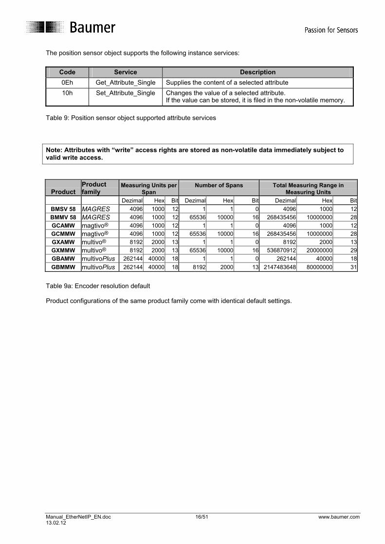
The position sensor object supports the following instance services:
Code Service Description 0Eh Get_Attribute_Single Supplies the content of a selected attribute 10h Set_Attribute_Single Changes the value of a selected attribute.
If the value can be stored, it is filed in the non-volatile memory. Table 9: Position sensor object supported attribute services Note: Attributes with “write” access rights are stored as non-volatile data immediately subject to valid write access.
Product
Product family
Measuring Units per Span
Number of Spans
Total Measuring Range in Measuring Units
Dezimal Hex Bit Dezimal Hex Bit Dezimal Hex BitBMSV 58 MAGRES 4096 1000 12 1 1 0 4096 1000 12BMMV 58 MAGRES 4096 1000 12 65536 10000 16 268435456 10000000 28GCAMW magtivo® 4096 1000 12 1 1 0 4096 1000 12GCMMW magtivo® 4096 1000 12 65536 10000 16 268435456 10000000 28GXAMW multivo® 8192 2000 13 1 1 0 8192 2000 13GXMMW multivo® 8192 2000 13 65536 10000 16 536870912 20000000 29GBAMW multivoPlus 262144 40000 18 1 1 0 262144 40000 18GBMMW multivoPlus 262144 40000 18 8192 2000 13 2147483648 80000000 31
Table 9a: Encoder resolution default Product configurations of the same product family come with identical default settings.

Manual_EtherNetIP_EN.doc 17/51 www.baumer.com 13.02.12
4.5. Assembly Object – 04hex The assembly object is created in accordance with the Common Industrial Protocol Specification. The object revision is 2. The class code is 04h. The provided class attributes are listed in table 10. Class attributes are addressed via the instance 0. All instances of the assembly object are static instances. Dynamic instances are not supported. The service - 0Eh Get Attribute single can be applied on the class attributes of the assembly object. Attribute ID
Access Name Data type Description Values
1 read Revision UINT Object revision 2 2 read Max Instance UINT Highest instance number
existing in this class 110
3 read Number of Instances
UINT Number of existing instances
6
Optional attribute list
STRUCT of List of supported optional instance attributes
number of attributes UINT Number of supported optional instance attributes
1
4 read
optional attributes ARRAY of UINT
List of optional instance attribute numbers
4
6 read Maximum ID Number Class Attributes
UINT Attribute number of last class attribute
7
7 read Maximum ID Number Instance Attributes
UINT Attribute number of last instance attribute
4
Table 10: Class attributes of the assembly object The following table contains all supported instance attributes of the assembly object. Attribute ID
Access Name Data type
Description Values
3 read Data ARRAY of BYTE
Data of the assembly instance
4 read Size UINT Number of bytes in attribute 3
See table 13
Table 11: Assembly object, instance attribute The service - 0Eh Get Attribute single can be applied on the instance attributes of the assembly object.
Manual_EtherNetIP_EN.doc 18/51 www.baumer.com 13.02.12
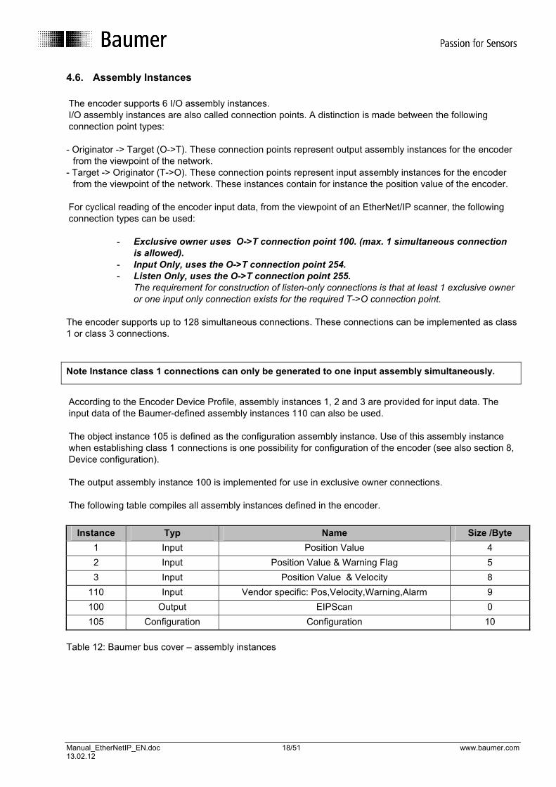
4.6. Assembly Instances The encoder supports 6 I/O assembly instances. I/O assembly instances are also called connection points. A distinction is made between the following connection point types:
- Originator -> Target (O->T). These connection points represent output assembly instances for the encoder
from the viewpoint of the network. - Target -> Originator (T->O). These connection points represent input assembly instances for the encoder
from the viewpoint of the network. These instances contain for instance the position value of the encoder. For cyclical reading of the encoder input data, from the viewpoint of an EtherNet/IP scanner, the following connection types can be used:
- Exclusive owner uses O->T connection point 100. (max. 1 simultaneous connection is allowed).
- Input Only, uses the O->T connection point 254. - Listen Only, uses the O->T connection point 255.
The requirement for construction of listen-only connections is that at least 1 exclusive owner or one input only connection exists for the required T->O connection point.
The encoder supports up to 128 simultaneous connections. These connections can be implemented as class 1 or class 3 connections. Note Instance class 1 connections can only be generated to one input assembly simultaneously.
According to the Encoder Device Profile, assembly instances 1, 2 and 3 are provided for input data. The input data of the Baumer-defined assembly instances 110 can also be used. The object instance 105 is defined as the configuration assembly instance. Use of this assembly instance when establishing class 1 connections is one possibility for configuration of the encoder (see also section 8, Device configuration). The output assembly instance 100 is implemented for use in exclusive owner connections. The following table compiles all assembly instances defined in the encoder.
Instance Typ Name Size /Byte
1 Input Position Value 4 2 Input Position Value & Warning Flag 5 3 Input Position Value & Velocity 8
110 Input Vendor specific: Pos,Velocity,Warning,Alarm 9 100 Output EIPScan 0 105 Configuration Configuration 10
Table 12: Baumer bus cover – assembly instances

Manual_EtherNetIP_EN.doc 19/51 www.baumer.com 13.02.12
The data formats of the assembly instances are listed in the table below.
Instance Byte Bit7 Bit6 Bit5 Bit4 Bit3 Bit2 Bit1 Bit0
0 Position LSB
1 Position
2 Position
1
3 Position MSB
0 Position LSB
1 Position
2 Position
3 Position MSB
2
4 Warn Flag
Alarm Flag
0 Position LSB
1 Position
2 Position
3 Position MSB
4 Velocity LSB
5 Velocity
6 Velocity
3
7 Velocity MSB
0 Position value LSB
1 Position value
2 Positionswert
3 Positionswert MSB
4 Velocity LSB
5 Velocity
6 Velocity
7 Velocity MSB
110
8 Warn Flag
Alarm Flag
Inpu
t Ass
embl
y In
stan
ces
Instance Byte Bit7 Bit6 Bit5 Bit4 Bit3 Bit2 Bit1 Bit0
0 Measuring Units per Span LSB
1 Measuring Units per Span
2 Measuring Units per Span
3 Measuring Units per Span MSB
4 Total Measuring Range LSB
5 Total Measuring Range
6 Total Measuring Range
7 Total Measuring Range MSB
8 Direction Counting Toggle
105
9 reserved
Con
figur
atio
n A
ssem
bly
Inst
ance
Table 13: Assembly instance data formats.

Manual_EtherNetIP_EN.doc 20/51 www.baumer.com 13.02.12
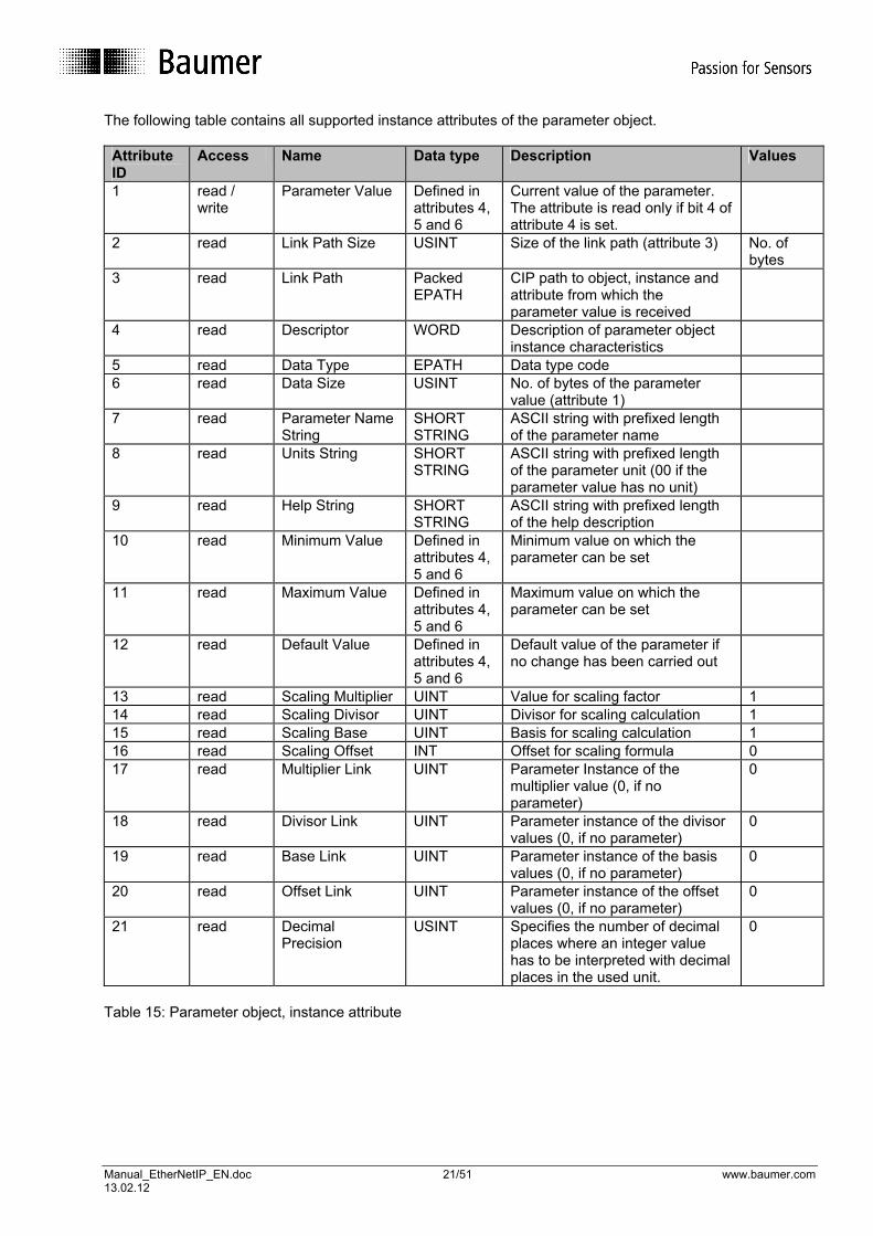
4.7. Parameter Object – 0Fhex The parameter object is implemented in compliance with the CIP Specification. The object revision is 1. The class code is 0Fh. In Table 14, the provided class attributes are listed. Class attributes are addressed via instance 0. The service - 0Eh Get Attribute single can be applied on the class attributes of the parameter object. Attribute ID
Access Name Data type Description Values
1 read Revision UINT Object revision 1 2 read Max Instance UINT Highest instance number
existing in this class 14
3 read Number of Instances
UINT Number of existing instances
14
Optional attribute list
STRUCT of List of supported optional instance attributes
Number of attributes
UINT Number of supported optional instance attributes
0
4 read
Optional attributes ARRAY of UINT
Number of optional instance attribute numbers
0
8 read Parameter Class Descriptor
WORD Bit information which describes the parameters
0x000B
9 read Configuration Assembly Instance
UINT Instance number of the configuration assembly instance
105
Table 14: Class attributes of the parameter object The class attribute 8 Parameter Class Descriptor provide the following bit information: Bit 0: = 1 A parameter object instance is available for each parameter. Bit 1: = 1 Each parameter instance contains all attributes. Bit 2:= 0 Automatic data saving upon writing of error-free response Bit 3: = 1 Non-volatile saving of all parameters
Manual_EtherNetIP_EN.doc 21/51 www.baumer.com 13.02.12
The following table contains all supported instance attributes of the parameter object. Attribute ID
Access Name Data type Description Values
1 read / write
Parameter Value Defined in attributes 4, 5 and 6
Current value of the parameter. The attribute is read only if bit 4 of attribute 4 is set.
2 read Link Path Size USINT Size of the link path (attribute 3) No. of bytes
3 read Link Path Packed EPATH
CIP path to object, instance and attribute from which the parameter value is received
4 read Descriptor WORD Description of parameter object instance characteristics
5 read Data Type EPATH Data type code 6 read Data Size USINT No. of bytes of the parameter
value (attribute 1)
7 read Parameter Name String
SHORT STRING
ASCII string with prefixed length of the parameter name
8 read Units String SHORT STRING
ASCII string with prefixed length of the parameter unit (00 if the parameter value has no unit)
9 read Help String SHORT STRING
ASCII string with prefixed length of the help description
10 read Minimum Value Defined in attributes 4, 5 and 6
Minimum value on which the parameter can be set
11 read Maximum Value Defined in attributes 4, 5 and 6
Maximum value on which the parameter can be set
12 read Default Value Defined in attributes 4, 5 and 6
Default value of the parameter if no change has been carried out
13 read Scaling Multiplier UINT Value for scaling factor 1 14 read Scaling Divisor UINT Divisor for scaling calculation 1 15 read Scaling Base UINT Basis for scaling calculation 1 16 read Scaling Offset INT Offset for scaling formula 0 17 read Multiplier Link UINT Parameter Instance of the
multiplier value (0, if no parameter)
0
18 read Divisor Link UINT Parameter instance of the divisor values (0, if no parameter)
0
19 read Base Link UINT Parameter instance of the basis values (0, if no parameter)
0
20 read Offset Link UINT Parameter instance of the offset values (0, if no parameter)
0
21 read Decimal Precision
USINT Specifies the number of decimal places where an integer value has to be interpreted with decimal places in the used unit.
0
Table 15: Parameter object, instance attribute

Manual_EtherNetIP_EN.doc 22/51 www.baumer.com 13.02.12
The services - 01h Get Attribute all - 0Eh Get Attribute single -10h Set Attribute single can be used on the instance attributes of the parameter object The following bits of the instance attribute 4, descriptor can be set in the parameter instances of the Baumer bus cover and have the following meaning: Bit 4: The parameter value is read only and can only be read. Bit 5: The parameter value is updated in real time by the device. Note Writable parameter values are saved as non-volatile data in the device after a successful write access. Writing to the internal flash takes place when the new parameter value is distinguished from the old one and is accepted by the system as valid. By means of the scaling attributes (instance attributes 13 to 16 and 21), integer parameter values can be displayed in other formats. The following formula applies for calculation of the value to be depicted: ( Actual Value (Attr. 1) + Offset (Attr. 16) ) x Mult (Attr. 13) x Base (Attr. 15) Value to be depicted = (6) Div (Attr. 14) x 10 Precision (Attr. 21)
Note In the current firmware, only the default units (C = Count for position values) and CPS = Counts per second for velocity values) are supported by the encoder. Consequently the formula (6) always results in: Value to be depicted = Actual value (attr. 1) Parameter instances always contain attributes from instances of other objects (for path see parameter instance attribute 3) as a source. In table 16, the individual parameter instances are named with their sources and important characteristics. The functional significance of the parameter values corresponds to the functional description of the respective instance attributes of the source objects and is described in the relevant sections of the manual. .

Manual_EtherNetIP_EN.doc 23/51 www.baumer.com 13.02.12
Para-meter instance
Source object Source instance
Source attribute
Parameter name Minimum value
Maximum value
Default value
1 Position Sensor Object (23h)
1 12 DirCountToggle 0 1 0
2 Position Sensor Object (23h)
1 16 MeasUnitsPerSpan 1 See table 9.a
See table 9.a
3 Position Sensor Object (23h)
1 17 TotMeasRangeinUn See table 9.a
See table 9.a
See table 9.a
4 Position Sensor Object (23h)
1 19 PresetValue 0 Smaller than set overall measure-ment range (see parameter instance 3)
0
5 Position Sensor Object (23h)
1 10 PositionValue 0 Set overall measure-ment range (see parameter instance 3)
0
6 Position Sensor Object (23h)
1 42 PhysResolSpan See table 9.a
See table 9.a
See table 9.a
7 Position Sensor Object (23h)
1 43 NumberOfSpan See table 9.a
See table 9.a
See table 9.a
8 Position Sensor Object (23h)
1 46 AlarmFlag 0 1 0
9 Position Sensor Object (23h)
1 44 Alarms 0 D003hex 0
10 Position Sensor Object (23h)
1 45 SupportedAlarms D003hex D003hex D003hex
11 Position Sensor Object (23h)
1 49 WarningFlag 0 1 0
12 Position Sensor Object (23h)
1 47 Warnings 0 2010hex 0
13 Position Sensor Object (23h)
1 48 SupportedWarnings 2010hex 2010hex 2010hex
14 Position Sensor Object (23h)
1 24 Velocity 0 FFFFFFFFhex
0
Table 16: Parameter object instances - characteristics

Manual_EtherNetIP_EN.doc 24/51 www.baumer.com 13.02.12
5. EtherNet/IP-specific objects 5.1. Introduction The Baumer bus cover has two physical Ethernet ports P1 and P2 with integrated switch technology. Both physical ports use a common MAC address and a common IP address. Both ports support autonegotiation and automatically set the duplex mode and the interface speed. The EtherNet/IP-specific objects existing in the bus cover and their mutual relationships.
Fig. 3: Illustration of the existing EtherNet/IP-specific objects Writing to the communication interface of the Baumer bus cover is carried out by an instance of the TCP / IP interface object and a total of 3 instances of the Ethernet link object. Writing to the two physical Ethernet ports P1 and P2 is carried out by the instances 2 and 3 of the Ethernet link object. Instance 1 of the Ethernet link object is required for writing to the internal device port of the integrated switch.
Manual_EtherNetIP_EN.doc 25/51 www.baumer.com 13.02.12
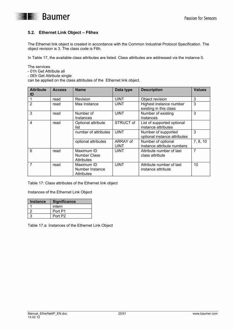
5.2. Ethernet Link Object – F6hex The Ethernet link object is created in accordance with the Common Industrial Protocol Specification. The object revision is 3. The class code is F6h. In Table 17, the available class attributes are listed. Class attributes are addressed via the instance 0. The services - 01h Get Attribute all - 0Eh Get Attribute single can be applied on the class attributes of the Ethernet link object. Attribute ID
Access Name Data type Description Values
1 read Revision UINT Object revision 3 2 read Max Instance UINT Highest instance number
existing in this class 3
3 read Number of Instances
UINT Number of existing instances
3
Optional attribute list
STRUCT of List of supported optional instance attributes
number of attributes UINT Number of supported optional instance attributes
3
4 read
optional attributes ARRAY of UINT
Number of optional instance attribute numbers
7, 8, 10
6 read Maximum ID Number Class Attributes
UINT Attribute number of last class attribute
7
7 read Maximum ID Number Instance Attributes
UINT Attribute number of last instance attribute
10
Table 17: Class attributes of the Ethernet link object Instances of the Ethernet Link Object Instance Significance 1 intern 2 Port P1 3 Port P2
Table 17.a: Instances of the Ethernet Link Object

Manual_EtherNetIP_EN.doc 26/51 www.baumer.com 13.02.12
The following table contains all supported instances of the Ethernet link object. Attribute ID
Access Name Data type
Description Values
1 read Interface Speed UDINT Current speed of the interface
2 read Interface Flags DWORD Interface status flags, see also the description below
3 read Physical Address ARRAY of 6 USINT
MAC address
7 read Interface Type USINT Interface type, see also the description below
8 read Interface State USINT General interface status, see also the description below
10 read Interface Label SHORT_STRING
Readable interface identification
Table 18: Ethernet link object, instance attributes Instance attribute 2 (interface flags) has the following meaning: Bit 0: Link Status: = 1 Active link exists Bit 1: Half/Full Duplex: = 0 Half duplex = 1 Full duplex Bits 2-4: Status Negotiation: = 0 Auto negotiation in execution = 1 Error in auto negotiation and speed detection. Default values are used. = 2 Error in auto negotiation but speed detected. The default value for the duplex mode is used. = 3 Auto negotiation successfully completed. Duplex Mode and speed detected. = 4 Auto negotiation not completed. Values for speed and duplex mode forced. Bit 5: Manual Settings required Reset: = 0 The interface can automatically adopt changes of attributes of the Ethernet link objects and does not require a reset for activation Bit 6: Local Hardware Fault: = 0 No hardware error detected = 1 Hardware error detected Bits 7-31: reserved The interface type (instance attribute 7) has the value 1 for internal interfaces (corresponds to instance 1 of the Baumer bus cover) or the value 2 (twisted pair interface for object instances 2 and 3). The interface state attribute (instance attribute 8) has the following meaning: 0: The interface status is unknown 1: The interface is ready to transmit and receive data 2: The interface is switched off 3: The interface is in the test mode 4-256: reserved The services - 0Eh Get Attribute single - 01h Get Attribute all can be applied on the instance attribute of the Ethernet link object.

Manual_EtherNetIP_EN.doc 27/51 www.baumer.com 13.02.12
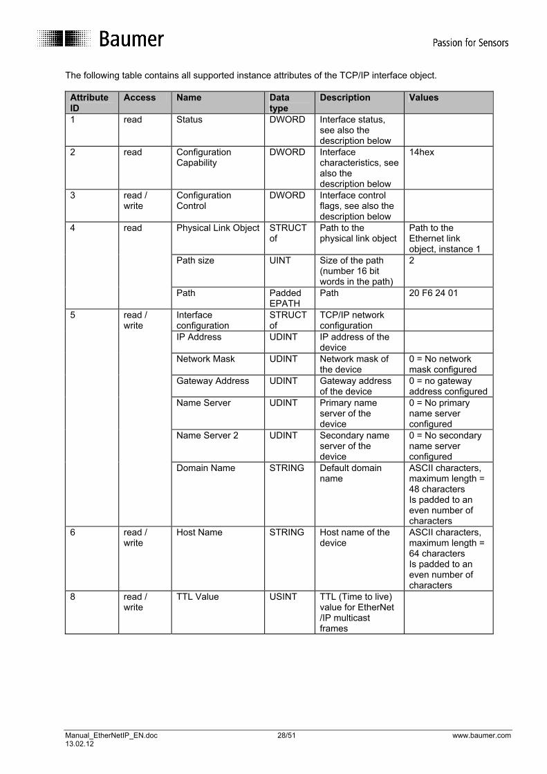
5.3. TCP/IP Interface Object – F5hex Das TCP/IP interface object is created in accordance with the CIP Specification. The object revision is 1. The class code is F5h. In Table 19, the available class attributes are listed. Class attributes are addressed via the instance 0. The services - 0Eh Get Attribute single - 01h Get Attribute all can be applied on the class attributes of the Ethernet interface object. Attribute ID
Access Name Data type Description Values
1 read Revision UINT Object revision 1 2 read Max Instance UINT Highest instance number
existing in this class 1
3 read Number of Instances
UINT Number of existing instances
1
Optional attribute list
STRUCT of List of supported optional instance attributes
number of attributes UINT Number of supported optional instance attributes
2
4 read
optional attributes ARRAY of UINT
List of optional instance attribute numbers
8, 9
6 read Maximum ID Number Class Attributes
UINT Attribute number of last class attribute
7
7 read Maximum ID Number Instance Attributes
UINT Attribute number of last instance attribute
9
Table 19: Class attributes of the TCP/IP interface object
Manual_EtherNetIP_EN.doc 28/51 www.baumer.com 13.02.12
The following table contains all supported instance attributes of the TCP/IP interface object. Attribute ID
Access Name Data type
Description Values
1 read Status DWORD Interface status, see also the description below
2 read Configuration Capability
DWORD Interface characteristics, see also the description below
14hex
3 read / write
Configuration Control
DWORD Interface control flags, see also the description below
Physical Link Object STRUCT of
Path to the physical link object
Path to the Ethernet link object, instance 1
Path size UINT Size of the path (number 16 bit words in the path)
2
4 read
Path Padded EPATH
Path 20 F6 24 01
Interface configuration
STRUCT of
TCP/IP network configuration
IP Address UDINT IP address of the device
Network Mask UDINT Network mask of the device
0 = No network mask configured
Gateway Address UDINT Gateway address of the device
0 = no gateway address configured
Name Server UDINT Primary name server of the device
0 = No primary name server configured
Name Server 2 UDINT Secondary name server of the device
0 = No secondary name server configured
5 read / write
Domain Name STRING Default domain name
ASCII characters, maximum length = 48 characters Is padded to an even number of characters
6 read / write
Host Name STRING Host name of the device
ASCII characters, maximum length = 64 characters Is padded to an even number of characters
8 read / write
TTL Value USINT TTL (Time to live) value for EtherNet /IP multicast frames
Manual_EtherNetIP_EN.doc 29/51 www.baumer.com 13.02.12
Mcast Config STRUCT
of IP Multicast address configuration, see also description below
Alloc Control USINT Multicast address allocation control word, determines how addressed are allocated
reserved USINT ODVA, reserved for possible future upgrades
0
Num Mcast UINT Number of IP multicast addresses allocated for EtherNet/IP
9 read
Mcast Start Addr UDINT Start address from which the multicast addresses are allocated (class D address)
Table 20: TCP/IP interface object, instance attributes Attribute 1 (status) has the following meaning: Bits 0 - 3: Interface configuration Status: = 0 : The interface configuration attribute (attribute 5) has not been configured. = 1 : The interface configuration attribute (attribute 5) contains valid values taken from the BOOTP, DHCP or from the internal flash memory. = 2 : The interface configuration attribute (attribute 5) contains valid values taken from the hardware settings (HEX Rotary-switches). = 3 – 15: reserved Bit 4: Mcast Pending: = 1 : This bit is set if the TTL value attribute (attribute 8) or the mcast config attribute (attribute 9) has been changed and is deleted on the next device start. The configuration changes carried out are stored in the device. Bits 5 – 31: reserved Attribute 2 (configuration capability) has the following meaning: The device returns the value 14hex, which means: 04 hex: The bus cover has DHCP client functionality and can acquire the network configuration via DHCP. 10 hex: The interface configuration attribute is writable.

Manual_EtherNetIP_EN.doc 30/51 www.baumer.com 13.02.12
Note The device does not have a DNS client and does not transmit the host name in the DHCP request. Using attribute 3 (configuration control) it is possible to set how the device acquires the initial setting of the interface configuration attribute (attribute 5). A change of attribute 3 (configuration control) without error message is immediately stored in the device’s internal flash memory. The following values can be set: 0: The device reads its configuration from the internal flash memory
or from Hardware-Rotary switches. 2: The device acquires its configuration via DHCP (default setting). Note When changing the attribute value from 2 to 0, the interface configuration setting (attribute 5) is also stored in the internal flash memory of the device. For this reason, the attribute value 0 is only accepted if the interface configuration (attribute 5) contains valid values at this point in time. The value of alloc control as a component of the mcast config (attribute 9) has the following meaning: 0: For generation of the multicast addresses, the specified allocation algorithm is used. If this value
is written, the values for Num Mcast and Mcast Start Addr of the Attribute in the set access must be transferred with 0.
1: The multicast addresses are allocated in accordance with the value for Num Mcast and Mcast Start Addr of the attribute.
2: Reserved The services
- 0Eh Get Attribute single - 01h Get Attribute all - 10h Set Attribute single - 02h Set Attribute all
can be applied on the instance attributes TCP/IP interface object.

Manual_EtherNetIP_EN.doc 31/51 www.baumer.com 13.02.12
6. Commissioning 6.1. Mechanical mounting Shaft encoders • Mount the encoder with the help of the mounting holes and three screws (square flange: 4 screws)
provided at the encoder flange. Observe thread diameter and depth. • There is an alternative mounting option in any angular position by eccentric fixings, see under
accessories. • Connect drive shaft and encoder shaft by using an appropriate coupling. The shaft ends must not touch
each other. The coupling must compensate temperature and mechanical tolerances. Observe the maximum permitted axial or radial shaft load. For appropriate couplings please refer to accessories.
• Tighten the mounting screws firmly. End shaft/hollow shaft encoders • Mounting by clamping ring
Prior to mounting the encoder open the clamping ring completely. Push encoder onto the drive shaft and tighten the clamping ring firmly.
• Adjusting element with rubber buffer Push the encoder onto the drive shaft and insert the cylindrical pin into the adjusting element (customer-mounted) and the rubber buffer.
• Mounting angle Push the encoder onto the drive shaft. Insert adjusting angle into the encoder’s rubber buffer and fasten the mounting angle at the contact surface.
• Stud screw Push the encoder onto the drive shaft and insert the stud screw (customer-mounted) into the encoder’s rubber buffer.
• Spring washer Fasten the spring washer at the mounting holes of the encoder housing using screws. Push the encoder onto the drive shaft and mount the spring washer to the contact surface.
6.2. Electrical connection Ever store and transport the bus cover in the ESD bag only. For electrical connection remove the bus cover as follows: • Release the fastening screws of the bus cover • Carefully loosen the bus cover and lift off in an axial direction 6.2.1. Cabling EtherNet/IP utilizes Fast Ethernet cable (100MBit, Cat 5) composed of four wires AWG22 (white, yellow, blue and orange). There are three types of EtherNet/IP cables:
• Type A – for fix or rigid cabling • Type B – for occasional movements or vibrations (flexible) • Type C – for permanent movements (highly flexible).

Manual_EtherNetIP_EN.doc 32/51 www.baumer.com 13.02.12
6.2.2. Connecting the bus cover The bus cover provides three M12 connectors. Two M12 connectors (D-coded, according IEC 61076-2-101) serve for EtherNet/IP implementation. Shaft / end shaft encoder
HEX rotary switches for IP address (only shaft encoder)
P2 L/A P1
Duo-LED Indicating the operating state green-red Activity LEDs (green) Indicating the bus activities on Port1, Port2
Fig. 4a: Bus cover shaft / end shaft – electrical assignment and LED Hollow shaft encoder
Duo-LED Indicating the operating state green-red
Fig. 4b: Bus cover hollow shaft– electrical assignment and LED • For voltage supply use A-coded M12 connector only. • For the bus lines both D-coded M12 connectors may be used at will. • Seal up the unused cable gland using a sealing bolt (included in the delivery). The IP address can be set via two HEX rotary switches (only shaft encoder) inside the bus cover (see section 7). There is no need to carry out further manual settings inside the bus cover.

Manual_EtherNetIP_EN.doc 33/51 www.baumer.com 13.02.12
Pin assignment
Supply voltage
1
34
2
EtherNet/IP (data line)
43
12
1 x M12 (connector) 2 x mating M12 (female) A-coded D-coded Pin Assignment Pin Assignment 1 UB (10...30 VDC) 1 TxD+ 2 N.C. 2 RxD+ 3 GND 3 TxD- 4 N.C. 4 RxD- Assembly of basic encoder and bus cover • Carefully plug the bus cover onto the D-SUB connector of the basic encoder, then press it over the seal
and take care not to tilt. • Tighten both fastening screws firmly in the same direction. • The bus cover must fully rest on the housing of the basic encoder and be firmly screwed on. The encoder housing and braided shield of the connecting cable are only ideally connected if the bus cover is resting fully on the basic encoder (form-locking)..

Manual_EtherNetIP_EN.doc 34/51 www.baumer.com 13.02.12
6.3. Operating display (multi-colour LED) A DUO LED (green and red) is located in the bus cover. This reflects the machine status of the position sensor object in accordance with Ethernet/IP specifications and provides information on the encoder status. LED status Status Description Off Not connected No power supply Green flashing Device is active and online, no
connection exists The device is operating under normal conditions and is online. No connection has been established to a scanner. - Encoder has not yet been configured by the
scanner - Configuration not complete or faulty
Green Device is active and online Connections have been established
The device is operating under normal conditions and is online, connections are in the Established status
Red Critical device fault or critical communication error
The device is in an irreparable error status
Red flashing Recoverable fault I/O connections are in the time-out status 2 Hz green/red Self test Immediately on connection of supply voltage, the
device carries out a self-test. Table 22: LED operating display statuses 6.4. Activity display (green LEDs) In the bus cover, another two green LEDs are integrated. These indicate data traffic at the two ports P1 and P2. In case of occasional data traffic (e.g. during ramp-up), the LEDs flash intermittently, but in the event of fast cyclical data exchange can appear as if permanently on. Immediately after connection of the supply voltage, both LEDs carry out a self test with a frequency of 2 Hz.
Manual_EtherNetIP_EN.doc 35/51 www.baumer.com 13.02.12
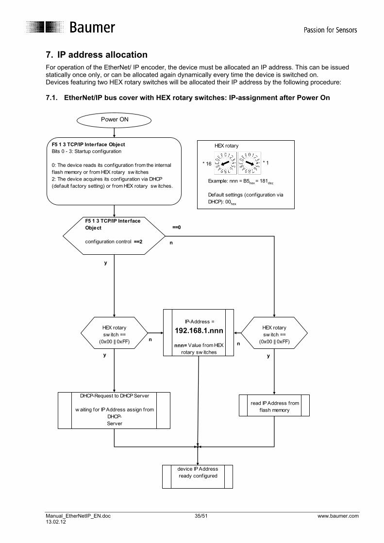
7. IP address allocation For operation of the EtherNet/ IP encoder, the device must be allocated an IP address. This can be issued statically once only, or can be allocated again dynamically every time the device is switched on. Devices featuring two HEX rotary switches will be allocated their IP address by the following procedure: 7.1. EtherNet/IP bus cover with HEX rotary switches: IP-assignment after Power On
F5 1 3 TCP/IP Interface Object
configuration control ==2
HEX rotary sw itch ==
(0x00 || 0xFF)
read IP Address from flash memory
IP-Address =
192.168.1.nnn
nnn= Value from HEX rotary sw itches
DHCP-Request to DHCP Server
w aiting for IP Address assign from DHCP-Server
device IP Address ready configured
Power ON
HEX rotary sw itch ==
(0x00 || 0xFF)
F5 1 3 TCP/IP Interface ObjectBits 0 - 3: Startup configuration
0: The device reads its configuration from the internal f lash memory or from HEX rotary sw itches2: The device acquires its configuration via DHCP (default factory setting) or from HEX rotary sw itches.
==0
y
Example: nnn = B5hex = 181dez
Default settings (configuration via DHCP): 00hex
* 16 * 1
HEX rotary
y y
nn
n

Manual_EtherNetIP_EN.doc 36/51 www.baumer.com 13.02.12
7.2. Allocate IP address with BOOTP/DHCP configuration tool Factory Device default is mode „IP Address over DHCP-Request“ The IP address must be allocated by a DHCP server. This DHCP server (software) can be obtained as freely available software from the Allen-Bradley Rockwell website. www.ab.com/networks/ethernet/bootp.html The DHCP server must be in the same network as the encoder. Carry out the relevant settings under Tools, Network Settings
After installation, a connected Ethernet/IP encoder registers as follows:
Fig. 5:DHCP server tool
Using the Disable BOOT/DHCP button (answer on successful execution: Command successful) this IP address can be statically allocated, i.e. the next time the encoder is switched on and off, no further request is sent to the DHCP Server. The encoder operates from now on with the previously assigned IP address. „IP address out of internal flash“. Note: Please carefully put down any updated IP address in the field provided on the product label (to prevent any future problems in operation in other networks, refer also to annex FAQs.)
MAC address of the Ethernet/IP encoder, see label on the bus cover housing
This IP address is allocated by the DHCP Server
Example: Product label with hand-written IP address
Manual_EtherNetIP_EN.doc 37/51 www.baumer.com 13.02.12
Instance attributes 3 of TCP/IP object, class code: F5Hex holds IP Addressing Mode
Class ID Attribute ID
Access Name Data type Description
0xF5 3 read/ write
Configuration Attribute
DWORD Determines how the device receives its initial configuration after switching on
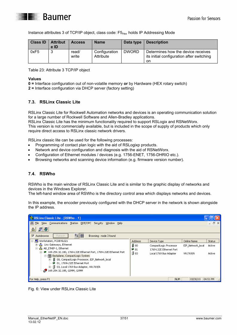
Table 23: Attribute 3 TCP/IP object Values 0 = Interface configuration out of non-volatile memory or by Hardware (HEX rotary switch) 2 = Interface configuration via DHCP server (factory setting) 7.3. RSLinx Classic Lite RSLinx Classic Lite for Rockwell Automation networks and devices is an operating communication solution for a large number of Rockwell Software and Allen-Bradley applications. RSLinx Classic Lite has the minimum functionality required to support RSLogix and RSNetWorx. This version is not commercially available, but is included in the scope of supply of products which only require direct access to RSLinx classic network drivers. RSLinx classic lite can be used for the following processes: • Programming of contact plan logic with the aid of RSLogixp products. • Network and device configuration and diagnosis with the aid of RSNetWorx. • Configuration of Ethernet modules / devices (e.g. 1756-ENET, 1756-DHRIO etc.). • Browsing networks and scanning device information (e.g. firmware version number). 7.4. RSWho RSWho is the main window of RSLinx Classic Lite and is similar to the graphic display of networks and devices in the Windows Explorer. The left-hand window area of RSWho is the directory control area which displays networks and devices. In this example, the encoder previously configured with the DHCP server in the network is shown alongside the IP address.
Fig. 6: View under RSLinx Classic Lite

Manual_EtherNetIP_EN.doc 38/51 www.baumer.com 13.02.12
8. Device configuration 8.1. Introduction On principle, the encoder with the parameters preset in the factory is ready for operation. Despite this, after setting the IP address as described in section 7, it will be necessary to adjust the encoder configuration for the relevant application. The encoder properties which will require adjusting include: - Sense of rotation / definition of the counting direction - Measurement range within a rotation - Total measurement range of the encoder - Matching the encoder coordinate system with the coordinate system of the application (preset value) All the specified characteristics are saved immediately following an error-free transmission as non-volatile values in the device. However, the save process is only initiated if a value is changed. A repeat transmission of identical values does not initiate a save routine. There are 3 independent mechanisms with identical rights available which can be used but which do not each individually have to be used. It makes sense and may be necessary to combine several different mechanisms (please observe the following note regarding setting the preset value). The next 3 sections describe examples of the encoder configuration for each of these mechanisms. Note Matching the coordinate systems using the preset value is not possible in the case of the configuration assembly instance, as transmission of the configuration assembly instance takes place with the Forward Open Frames function while establishing communication. Setting the position value is not customarily linked to the time at which a cyclical connection is established. The preset value can be set for instance by using the parameter object, while all other settings are carried out using the configuration assembly instance.
8.2. Using the parameter object When using the parameter object (class code 0Fhex), configuration takes place over the set attribute single service of the instance attribute (parameter value). In order to check the required setting value, the admissible setting range of the parameter can be previously determined by reading the minimum value (instance attribute 10) and the maximum value (instance attribute 11). As the setting limits of the encoder’s total measurement range are calculated at a certain time from the currently set measurement range within a revolution, the measurement range should be set within a revolution before the encoder’s total measurement range. Fig. 7 illustrates the schematic sequence of encoder configuration using the parameter object. If invalid setting values are written (e.g. setting value outside the setting range of the parameter), the encoder rejects the value with an error message (see Fig. 8, status = 0x03hex). If the set attribute single service is performed without errors, the status 0x00 hex is returned.

Manual_EtherNetIP_EN.doc 39/51 www.baumer.com 13.02.12
Encoder: CIP Success Encoder: CIP Success Encoder: CIP Success
Fig. 7: Encoder configuration with the parameter object
Encoder is placed at the preset position
Step 1 Setting the measurement range within a revolution
Object code = 0x0Fhex Instance = 2 Attribute number= 1 Service: CIP Set Attribute Single = 0x10hex
Step 2 Setting definition of the complete setting range of the encoder
Object code = 0x0Fhex Instance = 3 Attribute number= 1 Service: CIP Set Attribute Single = 0x10hex
Step 3 Setting definiton of the counting direction
Object code = 0x0Fhex Instance = 1 Attribute number= 1 Service: CIP Set Attribute Single = 0x10hex
Step 4 Setting the preset value (matching the coordinate systems)
Object code = 0x0Fhex Instance = 4 Attribute number= 1 Service: CIP Set Attribute Single = 0x10hex
Note: The preset value should be set at a standstill! Otherwise inaccuracies can occur!

Manual_EtherNetIP_EN.doc 40/51 www.baumer.com 13.02.12
Fig. 8: Record of a faulty set attribute single service From the viewpoint of the encoder, configuration of the setting values (steps 1 – 4 in Fig. 7) can only be carried out only once. From the point of view of the application, it can also make sense to execute steps 1 – 3 for instance after switching on the encoder. The parameter object also offers the possibility of reading out text strings for the parameter names, the parameter unit and a help text from the encoder in compliance with the “Common Industrial Protocol Specification”. The language used is English.

Manual_EtherNetIP_EN.doc 41/51 www.baumer.com 13.02.12
8.3. Application of the configuration assembly instance 105 When using configuration assembly instance 105, configuration of the encoder takes place with transmission in the Forward Open Frame while establishing the connection (see Fig. 9).
Fig. 9: Configuration assembly instance 105 in the Forward Open Frame As only one exclusive owner connection is accepted at any time by the bus cover (see also section 4.6), this connection type can be used, for example, in order to transmit the configuration assembly instance. The data structure of the assembly instance 105 is shown in table 13 on page 22. The data is taken individually from the bus cover in the following sequence: 1. Setting the measurement range within a revolution (measuring units per span) 2. Setting the total measurement range of the encoder (total measuring range in measuring units) 3. Setting the definition of the counting direction (direction counting toggle) Transfer of the configuration data takes place internally in the device via the parameter object. This ensures that the transfer of configuration values takes place after the same checks as with direct utilization of the parameter object (see section 8.2).

Manual_EtherNetIP_EN.doc 42/51 www.baumer.com 13.02.12
If an error is detected in the data of the configuration assembly instance, no connection is established. The connection is rejected on the part of the encoder with a connection failure frame (see Fig. 10, status = 0x01, additional status = 0x0118).
Fig. 10: Connection failure frame due to incorrect value in the assembly instance 105 Note Even with incorrect data in assembly instance 105, a part of the configuration data may have become effective! If for instance an incorrect value were written for the counting direction, but the values for setting the measurement range within a revolution and for setting the total measurement range of the sensor were still valid, then these two values would already have been accepted by the encoder before the connection was rejected.

Manual_EtherNetIP_EN.doc 43/51 www.baumer.com 13.02.12
When setting the preset value (matching the coordinate systems), note that the preset value has to be performed again with each change of the measurement range setting within a revolution, or of the encoder’s total measurement range (see section 4.4). For this reason, when using the assembly instance 105 for encoder configuration, ensure that before first setting the preset value (matching the coordinate system) error-free transmission of the assembly instance 105 has taken place at least once. From the point of view of the encoder, it is also the case for utilization of the configuration assembly instance that the encoder configuration only has to be transmitted once. From the point of view of the application, transmission must take place at least with each exclusive owner connection. 8.4. Direct application of the position sensor object The procedure for direct utilization of the position sensor object to configure the encoder only differs marginally from utilization of the parameter object (see section 8.2). Configuration takes place by means of the set attribute single service of the relevant instance attribute of the position sensor object (23hex). Direct writing of the position sensor object uses the same control functions for data checking as the parameter object. If invalid setting values are written (e.g. setting value outside the setting range of the attribute), the sensor rejects the value with an error message. (See also Fig. 8, status = 0x03hex). In the event of error-free execution of the set attribute single service, the status 0x00 hex is returned. From the point of view of the encoder, the configuration of setting values (steps 1 – 4 in Fig. 11) only needs to be performed once. However, from the point of view of the application, it may make sense for example to carry out steps 1- 3 every time the encoder is switched on.

Manual_EtherNetIP_EN.doc 44/51 www.baumer.com 13.02.12
Encoder: CIP Success Encoder: CIP Success Encoder: CIP Success
Fig. 11: Encoder configuration with the position sensor object
Encoder is placed at the preset position
Step 1 Setting the measurement range within a revolution
Object code = 0x23hex Instance = 1 Attribute number= 16 Service: CIP Set Attribute Single = 0x10hex
Step 2 Setting the total measurement range of the encoder
Object code = 0x23hex Instance = 1 Attribute number= 17 Service: CIP Set Attribute Single = 0x10hex
Step 3 Setting definition of the counting direction
Object code = 0x23hex Instance = 1 Attribute number= 12 Service: CIP Set Attribute Single = 0x10hex
Step 4 Setting the preset value (matching the coordinate systems)
Object code = 0x23hex Instance = 1 Attribute number= 19 Service: CIP Set Attribute Single = 0x10hex
Note: The preset value should be set at a standstill! Otherwise inaccuracies can occur!

Manual_EtherNetIP_EN.doc 45/51 www.baumer.com 13.02.12
9. RSLogix5000 project example 9.1. Reading in the input data
• Create a new project under RSLogix5000 • Select New Module • Select ETHERNET MODULE Generic Ethernet
Fig. 12: Generic Ethernet Module

Manual_EtherNetIP_EN.doc 46/51 www.baumer.com 13.02.12
9.1.1. Configure Generic Ethernet Module Select assembly instance (see chapter I/O assembly instances)
Fig. 13: Configuration assembly instances Select requested packet interval
Fig. 14: Define cycle time inputs Min. cycle time: 2 ms Max.cycle time: 3200ms
Manual_EtherNetIP_EN.doc 47/51 www.baumer.com 13.02.12
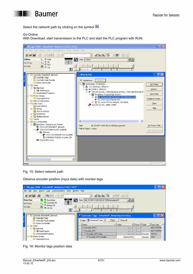
Select the network path by clicking on the symbol Go Online With Download, start transmission to the PLC and start the PLC program with RUN.
Fig. 15: Select network path Observe encoder position (input data) with monitor tags
Fig. 16: Monitor tags position data

Manual_EtherNetIP_EN.doc 48/51 www.baumer.com 13.02.12
9.2. Explicit Messaging, PLC Program Example, Set Preset Here: Set attribute single to class 0x23, instance 1, attribute 0x13
Fig. 17: Ladder logic depiction 9.2.1. Create program tags Create Msg_activate_SET for activation of the preset command
Fig. 18: Structure of Msg_activate_SET
Manual_EtherNetIP_EN.doc 49/51 www.baumer.com 13.02.12
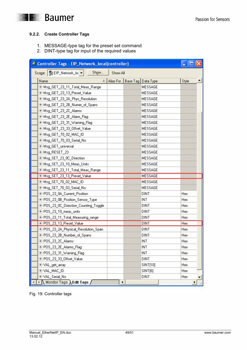
9.2.2. Create Controller Tags
1. MESSAGE-type tag for the preset set command 2. DINT-type tag for input of the required values
Fig. 19: Controller tags

Manual_EtherNetIP_EN.doc 50/51 www.baumer.com 13.02.12
9.2.3. Configuration of the message tag
Fig. 20: Set Attribute Single message configuration After downloading and running the PLC program, the preset command can now be executed with the button combination STRG-T.
Fig. 21: Activation of the preset command Here, the current position of the encoder is set to the preset value.

Manual_EtherNetIP_EN.doc 51/51 www.baumer.com 13.02.12
10. Used abbreviations and terms ARRAY Field data tape Attr. Attribute BOOL Data type which can only accept the values TRUE or FALSE BYTE Data type – 8 bit CIP Common Industrial Protocol DINT Signed 32-bit integer value DWORD Bit field – 32 bits EMC Electromagnetic compatibility ERTEC Enhanced Real-Time Ethernet Controller h Abbreviation for hexadecimal representation hex Abbreviation for hexadecimal representation I/O Input / output IP Internet protocol in conjunction with EtherNet/IP but industrial protocol OSI reference model Open Systems Interconnection Reference Model ODVA Open Device-Net Vendor Association Packed EPATH Data type – CIP path segments PE Potential earth SHORT_STRING Character string (1 byte per character, 1 byte length indicator) – Data type STRING Data type -.character string (1 byte per character) STRINGI International character string STRUCT Structure - data type TCP Transmission Control Protocol UDINT Unsigned 32-bit integer value UDP User Datagram Protocol UINT Unsigned 16-bit integer value USINT Unsigned 8-bit integer value WORD Bit field – 16 bits 11. FAQ‘s 11.1. Device not responding / IP address unknown Device operation mode „IP address out of internal flash“. The IP address is saved in the flash but unknown. Encoder is not recognised in RSLinx. (Device not responding to PING command) Troubleshooting:
• Carefully undock bus cover from basic encoder. • Switch on bus cover. Status indicator LED is red. • Bus cover is in mode „IP address over DHCP request“. • Assign bus address as described in chapter 7.2. • Press „Enable DHCP“. • Device logs on with „Command successful“. • Redock cover onto the basic encoder. • Device is now back to mode „IP address over DHCP request“
Devices with rotary switches:
• Carefully undock bus cover from basic encoder. • Rotary switch setting unequally 00, for example 22. • Device now in mode „IP address by HEX rotary switch“. • In the present example, the encoder will respond again to address 192.168.1.22 .