manual - eu
TRANSCRIPT

Model TA102A Zero Two Series Trip Amplifier Module For Combustible Gas
Applications
The information and technical data disclosed in this document may be used and disseminated only for the purposes and to the extent specifically authorized in writing by General Monitors. Instruction Manual 11/04 General Monitors reserves the right to change published specifications and designs without prior notice.
Part No. MANTA102A-EURevision M/11-04

Model TA102A
i
Warranty Statement General Monitors warrants the Model TA102A to be free from defects in workmanship or material under normal use and service within two (2) years from the date of shipment. General Monitors will repair or replace without charge any such equipment found to be defective during the warranty period. Full determination of the nature of, and responsibility for, defective or damaged equipment will be made by General Monitors’ personnel. Defective or damaged equipment must be shipped prepaid to General Monitors’ plant or the representative from which shipment was made. In all cases, this warranty is limited to the cost of the equipment supplied by General Monitors. The customer will assume all liability for the misuse of this equipment by its employees or other personnel. All warranties are contingent upon proper use in the application for which the product was intended and do not cover products which have been modified or repaired without General Monitors’ approval or which have been subjected to neglect, accident, improper installation or application, or on which the original identification marks have been removed or altered. Except for the express warranty stated above, General Monitors disclaims all warranties with regard to the products sold, including all implied warranties of merchantability and fitness and the express warranties stated herein are in lieu of all obligations or liabilities on the part of General Monitors for damages including, but not limited to, consequential damages arising out of/or in connection with the use or performance of the product.
Warnings WARNING - COMBUSTIBLE & FLAMMABLE GASES AND VAPORS ARE VERY DANGEROUS. EXTREME CAUTION SHOULD BE USED WHEN COMBUSTIBLE & FLAMMABLE GASES AND VAPORS ARE PRESENT. All Zero Two Series Modules contain components, which can be damaged by static electricity. Special care must be taken when wiring the system to ensure that only the connection points are touched. WARNING - suitably skilled and competent personnel must carry out Installation and Maintenance only. Full backward compatibility can be specified at the time of order. If this configuration is specified, the rear terminal output designations will be identical to the previous generation of Zero Two Series Modules. This generation of product can be distinguished from the previous generation by the lack of a door on the front panel. Adjustments are not necessary on the current generation of this product.

Model TA102A
ii
E C Declaration of Conformity in accordance with EC Directives
We at General Monitors Ireland Ltd., Ballybrit Business Park, Galway, Republic of Ireland, hereby declare that the equipment described below, both in its basic design and construction, and in the version or versions marketed by us, conforms to the relevant safety and health related requirements of the appropriate EC Directives, only as follows:
a) Conforms with the protection requirements of Council Directive 89/336/EEC, + Amd 92/31/68/EEC relating to Electromagnetic Compatibility, by the application of:
A Technical Construction File No: GM 95005 and Competent Body Certificate No. 4473-95-106 and Report No. 4473/1K8
And
b) Conforms with the protection requirements of IEC 1010-1 1990 + Amd 1: 1992 + Amd 2:1995 relating to safety by the application of:
A Technical Construction File No: GM 95005 and Competent Body Certificate No 4146/699L-6870, 4146/1119/9150 and 4146/1119/9507 issued by:
ERA Technology Ltd. Cleeve Road, Leatherhead Surrey KT22 7SB, England. Tel: +44 1372 367000
This declaration shall cease to be valid if modifications are made to the equipment without our approval. PRODUCT: Trip Amplifier Module for Combustible Gas Applications MODEL: TA102A It is ensured through internal measures and our ISO9001: 1994 certifications, that series production units conform at all times to the requirements of these current EC Directives and relevant standards. Responsible Person: Date: 15-07-97 General Manager European Operations The signatory acts on behalf of company management, and with full power of attorney

Model TA102A
iii
System Integrity Verification General Monitors’ mission is to benefit society by providing solutions through industry- leading safety products, services and systems that save lives and protect capital resources from the dangers of hazardous flames, gases and vapors. The safety products you have purchased should be handled carefully and installed, calibrated and maintained in accordance with the respective product instruction manual. Remember, these products are for your safety. To ensure operation at optimum performance, General Monitors recommends that certain maintenance items be performed. Commissioning Safety Systems Before power up, verify wiring, terminal connections and stability of mounting for all integral safety equipment including, but not limited to: • Power supplies • Control modules • Field detection devices • Signaling / output devices • Accessories connected to field and signaling devices After the initial application of power (and any factory specified warm-up period) to the safety system, verify that all signal outputs, to and from devices and modules, are within the manufacturers’ specifications. Initial calibration / calibration checking / testing should be performed per the manufacturers’ recommendations and instructions. Proper system operation should be verified by performing a full, functional test of all component devices of the safety system, ensuring that the proper levels of alarming occur. Fault/Malfunction circuit operation should be verified. Periodic Testing/Calibration of Field Devices Periodic testing/calibrating should be performed per the manufacturers’ recommendations and instructions. Testing/Calibrating procedures should include, but not be limited to: • Verify zero reading • Apply a known concentration of gas, or a simulated test device provided by the
manufacturer • Verify integrity of all optical surfaces and devices. When testing produces results outside of the manufacturers’ specifications, re-calibration or repair/replacement of the suspect device(s) should be performed as necessary. Calibration intervals should be independently established through a documented procedure, including a calibration log maintained by plant personnel, or third party testing services.

Model TA102A
iv
Periodic System Verification The following system verifications should be performed at least annually: Verify wiring, terminal connections and stability of mounting for all integral safety equipment including, but not limited to: • Power supplies • Control modules • Field detection devices • Signaling / output devices • Accessories connected to field and signaling devices. Proper system operation should be verified by performing a full, functional test of all component devices of the safety system, ensuring that the proper levels of alarming occur. Fault/Malfunction circuit operation should be verified. Calibration intervals should be independently established through a documented procedure, including a calibration log maintained by plant personnel, or third party testing services.

Model TA102AQuick-Start Guide
v
1.0 Quick-Start Guide
1.1 Upon Receipt of Equipment
All equipment shipped by General Monitors is packaged in shock absorbing containers, which provides considerable protection against physical damage. The contents should be carefully removed and checked against the packing slip. If any damage has occurred or if there is any discrepancy in the order, notify General Monitors as soon as possible. All subsequent correspondence with General Monitors must specify the equipment part and serial numbers. Each Model TA102A is completely checked at the factory; however, a complete checkout is necessary upon initial installation and start-up to ensure system integrity.
1.2 Sensor Location Considerations
There are no standard rules for sensor placement, since the optimum sensor location is different for each application. The customer must evaluate conditions at the sensor site in order to make this determination. WARNING – suitably skilled and competent personnel must carry out Installation and Maintenance only. 1.2.1 General Sensor Location Considerations • The sensor should be easily accessible for calibration checks. Ensure that sufficient
clearance exists to allow the use of field calibration devices. • The sensor head should always be pointing down to prevent water build up on the
sensing element. Remember that some combustible gases are heavier than air; however, do not rely too heavily on this fact when selecting a sensor position.
• The sensor should be located in areas where leaks are suspected (i.e. near valves & pipe connections, etc.).
• The sensor should not be placed where contaminating substances may coat it. 1.3 Sensor Poisons
Sensors may be adversely affected by prolonged exposure to certain atmospheres. The more important poisons are: • Prolonged exposure to Hydrogen Sulfide (H2S) Gas • Halides (compounds containing Fluorine, Chlorine, Bromine and Iodine) • Heavy Metals (e.g. Tetraethyl lead) Silicones contained in greases or aerosols are the most common “coating” agents. These are not true sensor poisons, but reduce sensor response. Other damaging materials, which attack the sensor physically, include mineral acids and caustic vapors. The presence of such poisons and vapors does not exclude the use of General Monitors Catalytic Bead Sensors. A careful analysis of ambient conditions should be undertaken and the customer should be aware that sensor calibration might need to occur at more frequent intervals.

Model TA102AQuick-Start Guide
vi
1.4 Control Module Installation
A rack or panel mounted chassis will be required when installing any Zero Two Series Module. These chassis’ should be mounted in non-hazardous, weather-protected locations and should be subjected to minimal shock and vibrations. The rack and panel mounted chassis are available in 4, 8, and 16 channel sizes. Multiple 16-channel chassis may be connected to each other to form larger systems. In installations where two or more module types are to be mixed in the same chassis, ensure that the individual coding strips match the channel application. The coding strips are pre-configured at the factory and the male portion is already on each module. The female portion, if un-mounted, must be fastened into position on the mounting strip of the desired chassis channel so as to mate with its counterpart on the module (see Figure 1).
Male Portion
Male Portion
1
2
3
4
5
6
7
8
9
10
11
12
2
4
6
8
10
12
14
16
18
20
22
24
26
28
30
32
Figure 1 – Control Module Coding Strip
NOTE - Zero Two series modules require air circulation to avoid excessive heat build-up. If chassis are stacked vertically within an enclosure, forced air circulation may be required. The Control Modules are, to a great extent, immune to electromagnetic interference (EMI). However, they should not be mounted in close proximity to radio transmitters or similar equipment.

Model TA102AQuick-Start Guide
vii
1.5 Rear Terminal Connections
All wire connections to the Model TA102A are made to the terminal block located at the rear of the chassis. The terminal block accepts 16 AWG to 20 AWG, stranded or solid core wire. 14 AWG wire may be used if it is properly stripped according to Figure 2.
Figure 2 – Wire Strip Length
CAUTION - Contact with PC Board components should be avoided in order to prevent damage by static electricity. To connect wires to the terminal block on the Model TA102A, loosen the desired screw, insert the stripped end of the wire and tighten. For the rear terminal designations refer to Figure 3 below:
Figure 3 – Rear Terminal Designations

Model TA102AQuick-Start Guide
viii
1.5.1 A2 Alarm The terminal designations for the A2 alarm outputs are:
LABEL TERM DESCRIPTION A2-C1 2d Relay Common (1 & 2) A2-1 4d Relay Contact A2-2 6d Relay Contact A2-3 8d Relay Contact A2-4 10d Relay Contact
A2-C2 12d Relay Common (3 & 4) A2-OC 14d Open Collector (OC)
LA2 24z OC Logic for A2 LED Figure 4 – A2 Alarm Outputs
The A2 alarm outputs are DPDT relays, 1 open collector output (A2-OC) that follows the logic of the relays and 1 open collector output (LA2) that follows the blinking pattern of the front panel LED. The A2-C1 designation is common for A2-1 & A2-2. The A2-C2 designation is common for A2-3 & A2-4. The normally open (NO) and normally closed (NC) contacts depend on a user selectable option (see Chapter 5). The table below refers to the proper open and closed A2 alarm relay contacts while the unit is on power:
Figure 5 – A2 Alarm Relay Contacts
1.5.2 A1 Alarm The terminal designations for the A1 Alarm outputs are:
Label Term Description A1-C1 2z Relay Common (1 & 2) A1-1 4z Relay Contact A1-2 6z Relay Contact A1-3 8z Relay Contact A1-4 10z Relay Contact
A1-C2 12z Relay Common (3 & 4) A1-OC 14z Open Collector (OC)
LA1 24d OC Logic for A1 LED
Figure 6a – A1 Alarm Outputs
The A1 Alarm outputs are DPDT relays, 1 open collector output (A1-OC) that follows the logic of the relays and 1 open collector output (LA1) that follows the blinking pattern of the front panel LED. The A1-C1 designation is common for A1-1 & A1-2. The A1-C2 designation is common for A1-3 & A1-4. The normally open (NO) and normally closed (NC) contacts depend on a user selectable option (see Chapter 5).
User Selected Relay State
Normally Open
Normally Closed
Normally Energized
A2-C1 & A2-1, A2-C2 & A2-4
A2-C1 & A2-2, A2-C2 & A2-3
Normally De-Energized
A2-C1 & A2-2, A2-C2 & A2-3
A2-C1 & A2-1, A2-C2 & A2-4

Model TA102AQuick-Start Guide
ix
The table below refers to the proper open and closed A1 alarm relay contacts while the unit is on power:
User Selected
Relay State Normally
Open Normally Closed
Normally Energized
A1-C1 & A1-1, A1-C2 & A1-4
A1-C1 & A1-2, A1-C2 & A1-3
Normally De-Energized
A1-C1 & A1-2, A1-C2 & A1-3
A1-C1 & A1-1, A1-C2 & A1-4
Figure 6b – A1 Alarm Relay Contacts
1.5.3 Fault Alarm The terminal designations for the Fault outputs are:
Label Term Description F-C 16z Relay Common F-1 18z Relay Contact (NO) F-2 20z Relay Contact (NC)
F-OC 22z Open Collector (OC) FUA 32d Open Collector (OC)
Figure 7 – Rear Terminal Designations for Fault Outputs
The Fault outputs are SPDT relays, 1 open collector output (F-OC) that follows the logic of the relays and 1 open collector output (FUA) dedicated to new fault indications. NOTE - If the Backward Compatible configuration is ordered, the FUA will not be present (pin 32d will be for +24VDC Input). The Fault outputs are always normally energized when power is applied to the module. The contact ratings for the A2 & A1 alarm and Fault relays are 4A @ 250 Vac, 3A @ 30 Vdc, Resistive, maximum. Inductive loads (bells, buzzers, relays, etc.) on dry relay contacts must be clamped down. Unclamped inductive loads can generate voltage spikes in excess of 1000 volts. Spikes of this magnitude may cause false alarms and contact damage. Figure 8 shows recommended relay protection circuits for AC and DC loads, respectively.
Figure 8 – Relay Protection Circuits for AC and DC Loads

Model TA102AQuick-Start Guide
x
1.5.4 Other Open Collector Outputs The terminal designation for the Unaccept and the Discrete Calibration / Inhibit Mode outputs are:
Label Term Description
UA-OC 18d Open Collector Output CAL/OC 32z CAL-Inhibit Mode Output
Figure 9 – Terminal Designations for Unaccept and Calibration Mode Outputs
NOTE - If the Backward Compatible configuration is ordered, the CAL/INH will not be present (pin 32z will be for the COM). The electrical rating for all open collector outputs is 100mA @ 35Vdc. Figure 10 illustrates some typical open collector external circuits.
Figure 10 – Open Collector External Circuits

Model TA102AQuick-Start Guide
xi
1.5.5 Field Device Connections The terminal designations for the Field Device are:
Term Description 26d,z Signal IN (analogue) 28d,z VDC Out (+24VDC) 30d,z DC Common
Figure 11 – Terminal Designations for Field Device
NOTE - Only 1 Field Device may be connected to a Model TA102A. Figure 12 illustrates the Field Device/Controller connections.
Figure 12 – Field Device/Controller Connections
1.5.6 Card Test Switch The terminal designation for the Card Test Input is:
Label Term Description
CT 16d Switch Connection
Figure 13 – Card Test Input

Model TA102AQuick-Start Guide
xii
Figure 14 is a block diagram that shows the switch connections for the Card Test feature.
Figure 14 – Switch Connections for Card Test
The Card Test Input is provided so that the user can access the Card Test feature remotely. One end of a normally open SPST switch is connected to this termination. The other end is connected to system common. To activate the feature, simply press and hold the switch for as long as the test time is to be run. 1.5.7 Analog Output Signal The terminal designations for the Analog Output Signal are:
Label Term Description AO+ 20d Analog Signal (plus) AO- 22d Analog Signal (minus)
Figure 15 – Terminal Designations for Analog Output
NOTE - If the Analog Signal is not used, a jumper must be placed between 20d & 22d. Figure 16 is a diagram of the Analog Signal connections.
Figure 16 – Analog Signal Connections

Model TA102AQuick-Start Guide
xiii
1.6 Applying Power
Zero Two Series Modules do not have an ON/OFF power switch. Each module in the Zero Two Series operates from 24Vdc. Current requirements will vary according to the number and type of modules in the system, as well as the number and type of field devices. NOTE - If the application of power does not turn ON the unit, check fuse F1 on the control board. NOTE - If the unit displays an F4 condition upon power-up first try to clear this condition by calibrating the sensor. If this condition persists, replace the sensor. Figure 17 indicates where the power connections for the chassis are made.
Figure 17 – Rear Power Connections

Model TA102A
xiv
NOTE - The instrument is now ready to operate! Please consult the manual for more information on the instrument’s many features. NOTE - If you have any problems in the setup or testing of the detector, please refer to the “Troubleshooting Section”, or call the factory direct. Worldwide Service is available by calling: Lake Forest, California Phone: +1-949-581-4464 (24 hr. service) Fax: +1-949- 581-1151
Houston, Texas Phone: +1-281-855-6000 Fax: +1-281-855-3290
Ireland Phone: +353-91-751175 Fax: +353-91-751317
Singapore Phone: +65-6748-3488 Fax: +65-6748-1911
United Arab Emirates Phone: +971-4-8815751 Fax: +971-4-8817927
United Kingdom Phone: +44-1625-619583 Fax: +44-1625-619098

Model TA102AQuick-Start Guide
Table of Contents
Warranty Statement .................................................................................................................................... i Warnings .................................................................................................................................... i System Integrity Verification.....................................................................................................................iii 1.0 Quick-Start Guide......................................................................................................................... v 1.1 Upon Receipt of Equipment ..................................................................................... v 1.2 Sensor Location Considerations .............................................................................. v 1.3 Sensor Poisons ........................................................................................................ v 1.4 Control Module Installation.......................................................................................vi 1.5 Rear Terminal Connections.....................................................................................vii 1.5.1 A2 Alarm.......................................................................................................viii 1.5.2 A1 Alarm.......................................................................................................viii 1.5.3 Fault Alarm.....................................................................................................ix 1.5.4 Other Open Collector Outputs......................................................................... x 1.5.5 Field Device Connections................................................................................xi 1.5.6 Card Test Switch .............................................................................................xi 1.6 Applying Power ......................................................................................................xiii 2.0 Introduction ................................................................................................................................. 5 2.1 General Description.................................................................................................. 6 2.2 Features & Benefits.................................................................................................. 7 2.2.1 Microprocessor Based Electronics.................................................................. 7 2.2.2 Setup Mode ..................................................................................................... 7 2.2.3 Password Option ............................................................................................. 7 2.2.4 Setup Check Mode.......................................................................................... 7 2.2.5 LED Test.......................................................................................................... 7 2.2.6 Card Test......................................................................................................... 7 2.2.7 Live Insertion/Removal.................................................................................... 7 2.3 Applications ........................................................................................................ 7 3.0 Installation ................................................................................................................................... 8 3.1 Upon Receipt of Equipment ..................................................................................... 8 3.2 Control Module Installation....................................................................................... 8 3.3 Rear Terminal Connections...................................................................................... 9 3.3.1 A2 Alarm........................................................................................................ 10 3.3.2 A1 Alarm........................................................................................................ 11 3.3.3 Fault Alarm .................................................................................................... 11 3.3.4 Other Open Collector Outputs....................................................................... 12 3.3.5 Field Device Connections.............................................................................. 13 3.3.6 Card Test Switch ........................................................................................... 14 3.4 Sensor Location Considerations ............................................................................ 16 3.4.1 General Sensor Location Considerations ..................................................... 16 3.5 Sensor Poisons ...................................................................................................... 16 3.6 Applying Power ...................................................................................................... 17

Model TA102A
2
3.7 Interconnecting cable guidelines............................................................................ 17 4.0 Operation 18 4.1 General Maintenance ............................................................................................. 18 4.2 Electrical Inputs ...................................................................................................... 18 4.3 Electrical Outputs ................................................................................................... 18 4.4 Accepting Alarm Conditions ................................................................................... 19 4.5 Resetting Latched Alarms ...................................................................................... 20 4.6 CAL Open Collector ............................................................................................... 20 4.7 Card Test Feature .................................................................................................. 21 4.8 Fault Diagnostics .................................................................................................... 21 4.8.1 F1, F2, F5 & F9 ............................................................................................. 21 4.8.2 F3 - Software checksum error ....................................................................... 21 4.8.3 F4 – Field Device Error ................................................................................. 21 4.8.4 F6 - Low supply voltage ................................................................................ 21 4.8.5 F7 - EEPROM verification failure .................................................................. 21 4.8.6 F8 - Failed to complete setup........................................................................ 21 5.0 User Interfaces 23 5.1 Types of User Interfaces ........................................................................................ 23 5.4 Setup & Setup Check Modes ................................................................................. 24 5.4.1 Entering the Password .................................................................................. 25 5.4.2 Inhibit Mode................................................................................................... 26 5.4.3 A2 Alarm Options .......................................................................................... 27 5.4.4 A1 Alarm Options .......................................................................................... 29 5.4.6 Fault/Inhibit Option ........................................................................................ 30 5.5 Inhibit Mode 34 5.6 Setup Mode Selection Block Diagram.................................................................... 35 6.0 Appendix ...................................................................................................... 36
6.1 Principle of Operation............................................................................................. 36 6.2 Applications and Accessories................................................................................. 37 6.2.1 Smart Sensors............................................................................................... 37 6.2.4 Dust Guard Assembly ................................................................................... 40 6.2.5 Duct Mounting Plates .................................................................................... 41 6.2.6 Calibration Equipment ................................................................................... 43 6.2.7 Calibration Check Mode ................................................................................ 44 6.2.8 Calibration Mode: .......................................................................................... 44 6.2.9 Calibration Check & Calibration Modes ........................................................ 44 6.2.10 Calibration Equipment and Part Numbers................................................... 45 6.3 System Specifications............................................................................................. 46 6.3.1 Application..................................................................................................... 46 6.3.2 Sensor Type .................................................................................................. 46 6.3.3 Typical Sensor Life........................................................................................ 46 6.3.4 Measuring Range .......................................................................................... 46 6.3.5 Accuracy........................................................................................................ 46 6.3.6 Zero Drift (Card & Sensor*) ........................................................................... 46 6.3.7 Stability (Card & Sensor*) ............................................................................. 46 6.3.8 Response Time (Card & Sensor* with CH4 gas) .......................................... 46

Model TA102A
3
6.3.9 Storage.......................................................................................................... 46 6.3.10 Warranty ...................................................................................................... 46 6.4 Mechanical Specifications ...................................................................................... 46 6.5 Electrical Specifications.......................................................................................... 47 6.5.1 Input Power Requirement.............................................................................. 47 6.5.2 Electrical Classification.................................................................................. 47 6.5.3 Relay Contact Rating .................................................................................... 47 6.5.4 Open Collector Rating ................................................................................... 47 6.5.5 Cable Parameters ......................................................................................... 47 6.6 Environmental Specifications ................................................................................. 48 6.6.1 Operating Temperature Range ..................................................................... 48 6.6.2 Storage Temperature Range......................................................................... 48 6.6.4 Operating Humidity Range............................................................................ 48 6.7 Engineering Specifications ..................................................................................... 49 6.7.1 Zero Two System .......................................................................................... 49 6.7.2 TA102A Control Module ................................................................................ 49 Volatile Liquids and Solvents ........................................................................................ 50 6.9 Engineering & Technical Drawings ........................................................................ 52 6.9.1 Outline & Terminal Connections.................................................................... 52 6.9.2 Final Assembly .............................................................................................. 53 6.10 Zero Two Series Modules ...................................................................................... 54 Customer Satisfaction Questionnaire ...................................................................................................... 55

Model TA102A
4
Table of Figures
Figure 1 – Control Module Coding Strip ..................................................................................................... vi Figure 2 – Wire Strip Length...................................................................................................................... vii Figure 3 – Rear Terminal Designations..................................................................................................... vii Figure 4 – A2 Alarm Outputs .................................................................................................................... viii Figure 5 – A2 Alarm Relay Contacts ........................................................................................................ viii Figure 6a – A1 Alarm Outputs .................................................................................................................. viii Figure 6b – A1 Alarm Relay Contacts ........................................................................................................ ix Figure 7 – Rear Terminal Designations for Fault Outputs.......................................................................... ix Figure 8 – Relay Protection Circuits for AC and DC Loads........................................................................ ix Figure 9 – Terminal Designations for Unaccept and Calibration Mode Outputs ........................................x Figure 10 – Open Collector External Circuits ..............................................................................................x Figure 11 – Terminal Designations for Field Device................................................................................... xi Figure 12 – Field Device/Controller Connections ....................................................................................... xi Figure 13 – Card Test Input........................................................................................................................ xi Figure 14 – Switch Connections for Card Test.......................................................................................... xii Figure 15 – Terminal Designations for Analog Output .............................................................................. xii Figure 16 – Analog Signal Connections .................................................................................................... xii Figure 17 – Rear Power Connections ...................................................................................................... xiii Figure 18 – Model TA102A..........................................................................................................................6 Figure 19 – Control Module Coding Strip ....................................................................................................9 Figure 20 – Wire Strip Length......................................................................................................................9 Figure 21 – Rear Terminal Designations...................................................................................................10 Figure 22 – Terminal Designations for A2 Alarm Outputs.........................................................................10 Figure 23 – A2 Alarm Relay Contacts .......................................................................................................11 Figure 24 – Terminal Designations for A1 Alarm Outputs.........................................................................11 Figure 25 – A1 Alarm Relay Contacts .......................................................................................................11 Figure 26 – Terminal Designations for Fault Outputs................................................................................11 Figure 27 – Recommended Relay Protection Circuits...............................................................................12 Figure 28 – Terminal Designations for Unaccept and Calibration.............................................................12 Figure 29 – Open Collector External Circuits ............................................................................................13 Figure 30 – Terminal Designations for the Field Device connections .......................................................13 Figure 31 – Field Device/Controller Connections ......................................................................................14 Figure 32 – Terminal Designation for Card Test Input ..............................................................................14 Figure 33 – Switch Connections for Card Test Feature ............................................................................14 Figure 34 – Terminal Designations for Analog Output ..............................................................................15 Figure 35 – Analog Signal Connections ....................................................................................................15 Figure 36 – Power Connections ................................................................................................................16 Figure 37 – Rear Terminal Relay Contacts ...............................................................................................18 Figure 38 – Front Panel Display ................................................................................................................23 Figure 47 – Entering Setup and Setup Check Modes ...............................................................................25 Figure 48 – Entering the Password ...........................................................................................................26 Figure 49 – Entering Inhibit Mode..............................................................................................................26 Figure 50 – A2 Energized/De-Energized Alarm Option.............................................................................27 Figure 51 – A2 Latching/Non-Latching Alarm Option................................................................................27 Figure 52 – A2 Alarm Set Point Option .....................................................................................................28 Figure 53 – A1 Energized-De-Energized Alarm Option ............................................................................29 Figure 54 – A1 Latching/Non-Latching Alarm Option................................................................................29 Figure 55 – A1 Set Point Option................................................................................................................30 Figure 56 – Fault Inhibit Option .................................................................................................................31 Figure 57 – Entering Card Test Options....................................................................................................31

Model TA102A
5
Figure 58 – Card Test Ramp Time ............................................................................................................32 Figure 59 – Alarm Output During A Card Test ..........................................................................................32 Figure 60 – Password Enabled/Disabled Option.......................................................................................33 Figure 61 – Entering A New Password......................................................................................................34 Figure 62 – Catalytic Sensor Diagram.......................................................................................................36 Figure 63 – S4100C Smart Sensor............................................................................................................37 Figure 64 – S4000C Smart Sensor............................................................................................................38 Figure 65 – IR2100 Model .........................................................................................................................39 Figure 66 – Splash-Guard Picture .............................................................................................................40 Figure 67 – Dust Guard Picture .................................................................................................................40 Figure 68 – Dust Guard Assembly Kit Picture ...........................................................................................40 Figure 69 – Duct Mounting Plate, Assembly Drawing ...............................................................................41 Figure 70 – IR2100 Duct Mounting Plate ..................................................................................................42 Figure 71 – Portable Purge Calibrator.......................................................................................................43 Figure 72 – 3-Liter Chamber......................................................................................................................43 Figure 73 – Recommended Maximum Cable Lengths Between Module & Field Device.........................47 Figure 74 – Maximum Allowable Cable Lengths Between Analog Output Connections On Control
Module...................................................................................................................................47 Figure 75 – Outline & Terminal Connections.............................................................................................52 Figure 76 – Final Assembly .......................................................................................................................53

Model TA102A
6
2.0 Introduction
This chapter provides a brief description of the Model TA102A, its features & benefits and a list of some of its applications. More detailed information on the features and benefits listed in Section 2.2 will be presented in later chapters.
WARNING - Installation and Maintenance must be carried out by suitably skilled and competent personnel only.
2.1 General Description
The General Monitors Model TA102A (see Figure 18) is a single channel Combustible Gas detection Control Module designed for use in Zero Two Series Gas and Flame Detection Systems. This Module connects to the wires from a field mounted General Monitors Catalytic Bead Sensor and monitors the presence of combustible gases and vapors. The Model TA102A is electrically and physically compatible with the other gas detection, flame detection and system modules in the Zero Two Series. It is distinguished from the other modules by its blue border and “TA102A" in the upper right corner of the front panel. The Model TA102A is designed for use in non-hazardous environments.
Figure 18 – Model TA102A

Model TA102A
7
2.2 Features & Benefits 2.2.1 Microprocessor Based Electronics Monitors fault conditions; sensor inputs and provides outputs in the form of display codes, analog signal, relay contact and open collector activation. 2.2.2 Setup Mode Allows the user to set parameters such as alarm output options, test options, etc. These parameters are viewed on the display during the Setup Mode. 2.2.3 Password Option Prevents unauthorized alteration of the setup parameters (can be disabled). 2.2.4 Setup Check Mode Allows the user to view the parameters that have been set by the factory and/or an operator. 2.2.5 LED Test Tests the integrity of each LED and each segment of the digital display on the front panel. 2.2.6 Card Test Tests the functionality of the card through the microprocessor, ramping the signal from 0 to full-scale. 2.2.7 Live Insertion/Removal Allows the user to insert or remove a module while power is applied to the system, without damage to any of the components in the system.
2.3 Applications
The General Monitors Model TA102A is a Combustible Gas Control Module designed for Zero Two Series Applications. Below is a partial list of applications: • Refineries • Drilling platforms and rigs • Gas and oil production platforms • Gas collection facilities • Oil well logging operations • LPG/LNG processing and storage • Gas Turbines • Solvent Vapors • Hydrogen Storage • Wastewater treatment plants • Chemical plants

Model TA102A
8
3.0 Installation
This chapter discusses what to do when a Model TA102A is received, the terminal connections & designations, sensor location considerations and what to be aware of when applying power.
3.1 Upon Receipt of Equipment
All equipment shipped by General Monitors is packaged in shock absorbing containers, which provides considerable protection against physical damage. The contents should be carefully removed and checked against the packing slip. If any damage has occurred or if there is any discrepancy in the order, notify General Monitors as soon as possible. All subsequent correspondence with General Monitors must specify the equipment part and serial numbers. Each Model TA102A is completely checked at the factory; however, a complete checkout is necessary upon initial installation and start-up to ensure system integrity.
3.2 Control Module Installation
A rack or panel mounted chassis will be required when installing any Zero Two Series Module. These chassis should be mounted in non-hazardous, weather-protected locations and should be subjected to minimal shock and vibrations. The rack and panel mounted chassis are available in 4, 8, and 16 channel sizes. Multiple 16-channel chassis may be connected to each other to form larger systems. In installations where two or more module types are to be mixed in the same chassis, ensure that the individual coding strips match the channel application. The coding strips are pre-configured at the factory and the male portion is already on each module. The female portion, if un-mounted, must be fastened into position on the mounting strip of the desired chassis channel so as to mate with its counterpart on the module (see Figure 19).

Model TA102A
9
Male Portion
Male Portion
1
2
3
4
5
6
7
8
9
10
11
12
2
4
6
8
10
12
14
16
18
20
22
24
26
28
30
32
Figure 19 – Control Module Coding Strip
NOTE – Equipment is to be installed in Rack System or cabinet meeting the fire enclosure requirements of IEC 1010-1
Zero Two series modules require air circulation to avoid excessive heat build-up. If chassis are stacked vertically within an enclosure, forced air circulation may be required. Permissible performance loss the user can expect in the presence of Radio Frequency Electromagnetic Field, per EN50082-2 : 1995 is: If the installation is subjected to a strong Radio Frequency Electromagnetic Field (10V/m @ 27-1000Mhz), the Control Module may respond with a display deviation of +/-10% FSD. This deviation will disappear following removal of the field. Functionality is otherwise unaffected.
3.3 Rear Terminal Connections
All wire connections to the Model TA102A are made to the terminal block located at the rear of the chassis. The terminal block accepts 16 AWG to 20 AWG (1.5mm2 to 0.75mm2), stranded or solid core wire. 14 AWG wire may be used if it is properly stripped according to Figure 20.
Figure 20 – Wire Strip Length

Model TA102A
10
CAUTION - Contact with PC Board components should be avoided in order to prevent damage by static electricity. To connect wires to the terminal block on the Model TA102A, loosen the desired screw, insert the stripped end of the wire and tighten. (Alternate connector styles available – contact the factory). For the rear terminal designations refer to Figure 21 below:
Figure 21 – Rear Terminal Designations
3.3.1 A2 Alarm The terminal designations for the A2 alarm outputs are:
Figure 22 – Terminal Designations for A2 Alarm Outputs
The A2 alarm outputs are DPDT relays, 1 open collector output (A2-OC) that follows the logic of the relays and 1 open collector output (LA2) that follows the blinking pattern of the front panel LED. The A2-C1 designation is common for A2-1 & A2-2. The A2-C2 designation is common for A2-3 & A2-4. The normally open (NO) and normally closed (NC) contacts depend on a user selectable option (see Chapter 5). The table below refers to the proper open and closed A2 alarm relay contacts while the unit is on power:
LABEL TERM DESCRIPTION A2-C1 2d Relay Common (1 & 2) A2-1 4d Relay Contact A2-2 6d Relay Contact A2-3 8d Relay Contact A2-4 10d Relay Contact
A2-C2 12d Relay Common (3 & 4) A2-OC 14d Open Collector (OC)
LA2 24z OC Logic for A2 LED (mimic)

Model TA102A
11
User Selected Relay State
Normally Open
Normally Closed
Normally Energized
A2-C1 & A2-1, A2-C2 & A2-4
A2-C1 & A2-2, A2-C2 & A2-3
Normally De-Energized
A2-C1 & A2-2, A2-C2 & A2-3
A2-C1 & A2-1, A2-C2 & A2-4
Figure 23 – A2 Alarm Relay Contacts
3.3.2 A1 Alarm The terminal designations for the A1 Alarm outputs are:
Label Term Description A1-C1 2z Relay Common (1 & 2) A1-1 4z Relay Contact A1-2 6z Relay Contact A1-3 8z Relay Contact A1-4 10z Relay Contact
A1-C2 12z Relay Common (3 & 4) A1-OC 14z Open Collector (OC)
LA1 24d OC Logic for A1 LED (mimic)
Figure 24 – Terminal Designations for A1 Alarm Outputs
The A1 Alarm outputs are DPDT relays, 1 open collector output (A1-OC) that follows the logic of the relays and 1 open collector output (LA1) that follows the blinking pattern of the front panel LED. The A1-C1 designation is common for A1-1 & A1-2. The A1-C2 designation is common for A1-3 & A1-4. The normally open (NO) and normally closed (NC) contacts depend on a user selectable option (see Chapter 5). The table below refers to the proper open and closed A1 alarm relay contacts while the unit is on power:
User Selected
Relay State Normally
Open Normally Closed
Normally Energized
A1-C1 & A1-1, A1-C2 & A1-4
A1-C1 & A1-2, A1-C2 & A1-3
Normally De-Energized
A1-C1 & A1-2, A1-C2 & A1-3
A1-C1 & A1-1, A1-C2 & A1-4
Figure 25 – A1 Alarm Relay Contacts
3.3.3 Fault Alarm The terminal designations for the Fault outputs are:
Label Term Description F-C 16z Relay Common F-1 18z Relay Contact (NO) F-2 20z Relay Contact (NC)
F-OC 22z Open Collector (OC) FUA 32d Open Collector (OC)
Figure 26 – Terminal Designations for Fault Outputs

Model TA102A
12
The Fault outputs are SPDT relays, 1 open collector output (F-OC) that follows the logic of the relays and 1 open collector output (FUA) dedicated to new fault indications. NOTE - If the Backward Compatible configuration is ordered, the FUA will not be present (pin 32d will be for +24VDC input). The contact ratings for the A2 & A1 alarm and Fault relays are 4A @ 30V RMS/42.4V Pk, 3A @ 30 VDC, Resistive, maximum. Inductive loads (bells, buzzers, relays, etc.) on dry relay contacts must be clamped down. Unclamped inductive loads can generate voltage spikes in excess of 1000 volts. Spikes of this magnitude may cause false alarms and contact damage. Figure 27 shows recommended relay protection circuits for AC and DC loads, respectively.
Figure 27 – Recommended Relay Protection Circuits
3.3.4 Other Open Collector Outputs The terminal designation for the Unaccept and the Discrete Calibration outputs are:
Label Term Description
UA 18d Open collector Output CAL/OC 32z CAL-Inhibit Mode Output
Figure 28 – Terminal Designations for Unaccept and Calibration
NOTE - If the Backward Compatible configuration is ordered, the CAL/INH will not be present (pin 32z will be for the COM). The electrical rating for all open collector outputs is 100mA @ 35Vdc.

Model TA102A
13
Figure 29 illustrates some typical open collector external circuits.
Figure 29 – Open Collector External Circuits
3.3.5 Field Device Connections The terminal designations for the Field Device connections are:
Term Description 26d,z Signal IN (analogue) 28d,z VDC Out (+24VDC) 30d,z DC Common
Figure 30 – Terminal Designations for the Field Device connections
NOTE - Only 1 sensor may be connected to a Model TA102A.

Model TA102A
14
Figure 31 illustrates the Field Device/Controller connections.
Figure 31 – Field Device/Controller Connections
3.3.6 Card Test Switch The terminal designation for the Card Test Input is:
Label Term Description
CT 16d Switch Connection
Figure 32 – Terminal Designation for Card Test Input
Figure 33 is a block diagram that shows the switch connections for the Card Test feature.
Figure 33 – Switch Connections for Card Test Feature
Model TA102A
15
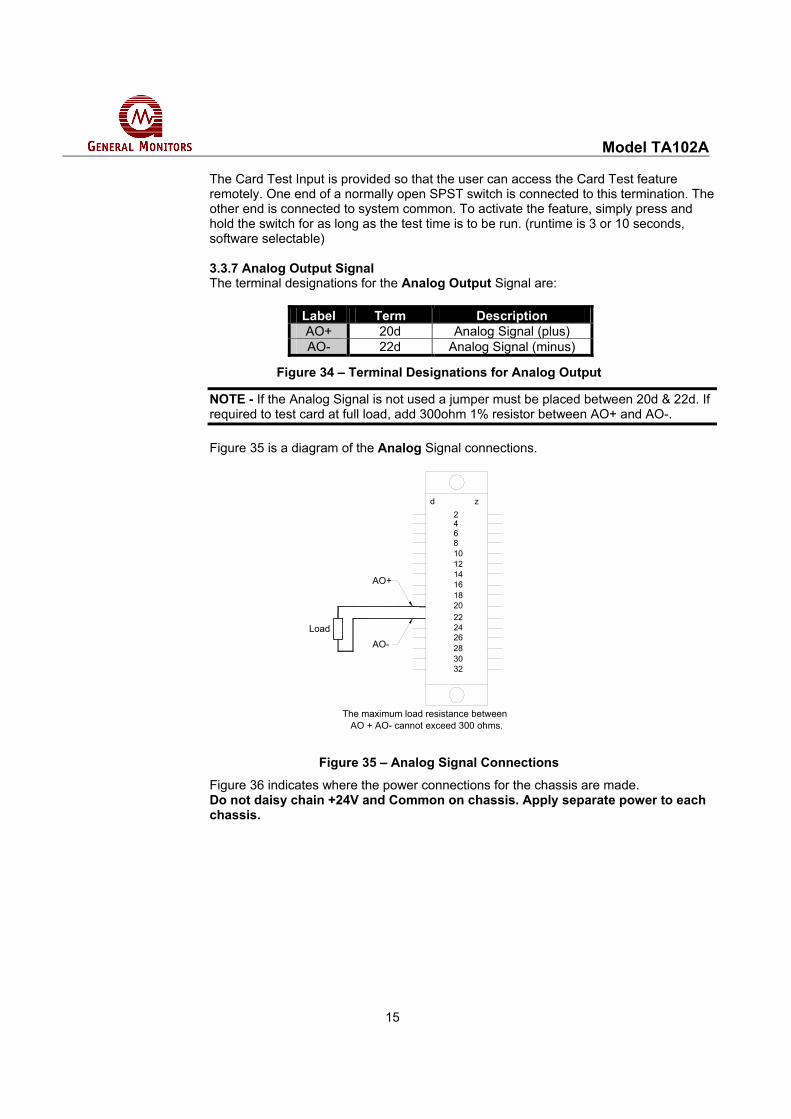
The Card Test Input is provided so that the user can access the Card Test feature remotely. One end of a normally open SPST switch is connected to this termination. The other end is connected to system common. To activate the feature, simply press and hold the switch for as long as the test time is to be run. (runtime is 3 or 10 seconds, software selectable) 3.3.7 Analog Output Signal The terminal designations for the Analog Output Signal are:
Label Term Description AO+ 20d Analog Signal (plus) AO- 22d Analog Signal (minus)
Figure 34 – Terminal Designations for Analog Output
NOTE - If the Analog Signal is not used a jumper must be placed between 20d & 22d. If required to test card at full load, add 300ohm 1% resistor between AO+ and AO-. Figure 35 is a diagram of the Analog Signal connections.
2468101214161820222426283032
d z
AO+
AO-Load
The maximum load resistance between AO + AO- cannot exceed 300 ohms.
Figure 35 – Analog Signal Connections
Figure 36 indicates where the power connections for the chassis are made. Do not daisy chain +24V and Common on chassis. Apply separate power to each chassis.

Model TA102A
16
Figure 36 – Power Connections
3.4 Sensor Location Considerations
There are no standard rules for sensor placement, since the optimum sensor location is different for each application. The customer must evaluate conditions at the sensor site in order to make this determination. WARNING – suitably skilled and competent personnel must carry out Installation and Maintenance only. 3.4.1 General Sensor Location Considerations • The sensor should be easily accessible for calibration checks. Ensure that sufficient
clearance exists to allow the use of field calibration devices such as a Portable Purge Calibrator for combustible gas applications.
• The sensor head should always be pointing down to prevent water build up on the sensing element. Remember that some combustible gases are heavier than air; however, do not rely too heavily on this fact when selecting a sensor position.
• The sensor should be located in areas where leaks are suspected (i.e. near valves & pipe connections, etc.).
• The sensor should not be placed where it may be coated by contaminating substances may coat it.
3.5 Sensor Poisons
Sensors may be adversely affected by prolonged exposure to certain atmospheres. The more important poisons are: • Prolonged exposure to Hydrogen Sulfide (H2S) Gas • Halides (compounds containing Fluorine, Chlorine, Bromine and Iodine) • Heavy Metals (e.g. Tetraethyl lead) Silicones contained in greases or aerosols are the most common “coating” agents. These are not true sensor poisons, but reduce sensor response. Other damaging materials, which attack the sensor physically, include mineral acids and caustic vapors. The presence of such poisons and vapors does not exclude the use of General Monitors Catalytic Bead Sensors. A careful analysis of ambient conditions should be undertaken and the customer should be aware that sensor calibration might need to occur at more frequent intervals.

Model TA102A
17
3.6 Applying Power
Zero Two Series Modules do not have an ON/OFF power switch. Each module in the Zero Two Series operates from 24Vdc. Current requirements will vary according to the number and type of modules in the system, as well as the number and type of field devices. NOTE - If the application of power does not turn ON the unit, check fuse F1 on the control board. NOTE - If the unit displays an F4 condition upon power-up first try to clear this condition by calibrating the sensor. If this condition persists, replace the sensor.
3.7 Interconnecting cable guidelines
The interconnecting cable should have an overall screen or screen and armour. Cables to BS5308 or equivalent are suitable. Note that the terms “screen” and “shield” are equivalent for the purposes of this manual. Interconnecting cables should be segregated from power and other “noisy cables. Avoid proximity to cables associated with radio transmitters, welders, switch mode power supplies, inverters, battery chargers, ignition systems, generators, switchgear, arc lights and other high frequency or high power switching process equipment. In general, maintain a separation of at least 1m between instrument and other cables. Greater separations are required where long parallel cable runs are unavoidable. Avoid running instrument cable trenches close to lightning conductor earth pits. General Monitors do not recommend the use of cable shoes or crimps on any junction box or housing wiring terminals. Poor crimping can cause bad connection when unit experiences temperature variations. We therefore recommend good practice is to just terminate cable or sensor wires as is, especially in remote sensor applications. Complete all cable insulation testing before connecting the cable at either end. Refer to Smart Sensor Manual for installation instructions.
Model TA102A
18
4.0 Operation
This chapter discusses what general maintenance to perform and describes the electrical inputs, outputs, accepting & resetting alarm & fault conditions and fault diagnostics.
4.1 General Maintenance (Also refer to leaflet T023 of BG Chemle)
Once the Model TA102A has been installed, very little maintenance is required other than periodic checks to verify the integrity of the system. • The user should evaluate conditions at the sensor site to determine how frequent
calibration checks should be performed. • A functional test of the system should be performed at least once each year. This
test should include full operation of stand-by systems or back up power for the prescribed period.
• The power, sensor and output wiring should be checked for tightness, verifying that all of the components and devices are connected correctly.
• If the “Password” is disabled, periodic checks of the setup parameters should be performed.
4.2 Electrical Inputs
There are two electrical inputs to the Model TA102A. They are the: • General Monitors Field Device and • Card Test input Both of these input connections (sensor and card test) are made to the rear terminal block (see Chapter 3 for more detailed installation information). • The Smart Sensor or Point IR Detector input consists of the three lead connections
used with General Monitors’ Field Devices (Common, Signal, +24VDC). Refer to figure 31.
• The Card Test input consists of a single termination for remote testing of the Model
TA102A’s functions. For detailed information on the Card Test, refer to Figure 33.
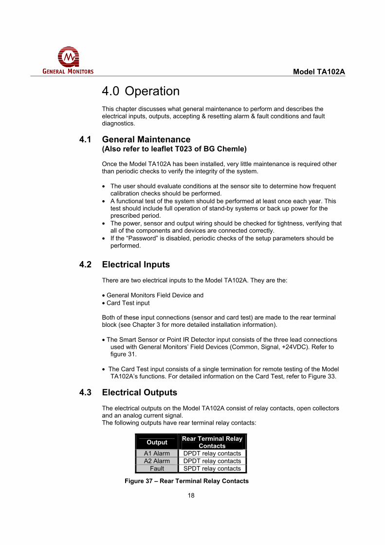
4.3 Electrical Outputs
The electrical outputs on the Model TA102A consist of relay contacts, open collectors and an analog current signal. The following outputs have rear terminal relay contacts:
Output Rear Terminal Relay Contacts
A1 Alarm DPDT relay contacts A2 Alarm DPDT relay contacts
Fault SPDT relay contacts
Figure 37 – Rear Terminal Relay Contacts
Model TA102A
19
All of the relay contacts on the Model TA102A have a maximum rating of: • 4A @ 30V RMS/42.4V Pk., 3A @ 30Vdc resistive The following outputs have rear terminal open collectors: • A1 Alarm & LED Mimic • A2 Alarm & LED Mimic • Fault • UA - Unaccepted Alarm • FUA - Unaccepted Fault • CAL - Calibration & Calibration Check Modes. Also indicates Inhibit Mode. All of the open collector outputs on the Model TA102A have a maximum rating of: • 100mA @ 35Vdc • The Analog Output Signal is used for sending gas concentrations and status
information to remote devices. The maximum analog load may not exceed 300 ohms including the wire/cable that the signal is sent on.
The Analog Output is a 0 to 21.7mA current signal with 4 to 20mA being proportional to 0 to 100% of full scale. When the Model TA102A is placed in the calibration, calibration check, setup, setup check or inhibit mode a 1.5mA signal is generated by this output. During the calibration mode the digital display will indicate prompts associated with the calibration procedure. During the calibration or the calibration check mode, the digital display on the TA102A will indicate CA if the CAL current is 1.5mA if the CAL current is 0mA the display on the TA102A will indicate F4 (field device error). When the Model TA102A enters into a fault condition a 0mA signal is generated by this output. During a fault the display will indicate a fault code (“F” followed by a digit). If the sensor attached to the Model TA102A is seeing gas in excess of 100% of full scale, this output will generate a signal between 20 and 21.7mA (not proportional). An over range condition is indicated by a flashing digital display reading full-scale (99). Overrange conditions are latching.
4.4 Accepting Alarm Conditions
Whenever a new alarm condition occurs, the front panel LED and open collector associated with that alarm (LA1 or LA2) would begin to flash. In addition, the associated alarm outputs and the unaccept outputs (TA102A UA open collector & FM002A UA relay) will activate, unless they are already activated. The flashing front panel alarm LED and rear terminal open collector indicate that a new alarm has been activated. New alarms should be acknowledged, or accepted. This is accomplished with the Master Accept Button located on the Facilities Module, (FM002A). Pressing the Master Accept Button de-activates the UA outputs and causes the associated front-panel alarm LED, and rear terminal open collector to stop flashing and energize. NOTE - Alarms that latch must be Accepted before they can be Reset (see Section 5.5).

Model TA102A
20
There is a unique situation that may occur with some frequency in certain applications. An alarm may occur and the operator will accept this alarm by pressing the Master Accept Button. If the alarm output is latching and the condition at the sensor returns to normal (safe) the alarm output will need to be reset, as previously stated in Section 4.4. If, however, the alarm output is not reset and that alarm set point is exceeded again, the front panel LED, the associated mimic open collector, and the unaccept outputs will re-flash or re-activate. This gives the operator an indication of a new alarm condition that must be re-accepted. A type of alarm, other than the A1 & A2 alarms, is the fault alarm. The fault alarm can be accepted similarly to the A1 & A2 alarms. The front panel Fault LED will flash and the fault unaccept (FUA) open collector will energize when a fault is detected. By pressing the Accept button on the front panel, the FUA output will de-energize and the Fault LED will stop flashing. It will stay illuminated until the fault condition is corrected.
4.5 Resetting Latched Alarms The user may select a “latching” or “non-latching” alarm output for A1 and/or A2. If an alarm output activates and the condition that caused that activation is no longer present, a non-latching alarm output will reset automatically. A latched alarm output needs to be reset manually. Resetting latched alarm outputs is accomplished with the Master Reset Button located on the Facilities Module (FM002A). Pressing the Master Reset Button will reset any latched conditions that are no longer valid. NOTE - Latched alarm conditions cannot be Reset until they have been Accepted (see Section 4.4). Whenever the Model TA102A receives a 20mA signal, or higher, the front panel alarm LEDs, the digital display and the rear terminal alarm outputs will latch until the input signal drops below the alarm set points and the Reset Button is pressed (twice if A1 or A2 have latching outputs). This lets the operator know that a combustible level is present at the field device. 4.5.1 LED Test The Master Reset Button performs another function. If the operator presses and holds the Master Reset Button for two or more seconds, all of the LED’s and LED segments in the digital display will illuminate for as long as the operator presses the button. This is called the LED Test. The LED test cannot be performed while the unit is in alarm or fault, or during a Card Test.
4.6 CAL Open Collector There is an open collector that will energize anytime the unit is put in the: • Calibration Mode • Calibration Check Mode This open collector output is referenced to the system’s ground/common. Energizing this output merely provides a path to ground as is the case with all energized open collector outputs. De-energized, this output will be in a high impedance state.

Model TA102A
21
4.7 Card Test Feature
The Card Test Input is provided so that the user can access the Card Test feature remotely. One end of a normally open SPST switch is connected to this termination and the other end is connected to system common (see Figure 33). To activate the Card Test feature, simply press and hold the switch. The front panel LED’s and digital display will begin ramping up at the start of the card test. They will continue to ramp-up for the software selectable ramp time specified by the operator (3 or 10 seconds) during the Setup Mode (see Section 5.4). Each alarm level (A1 & A2) will trip when the alarm set point is exceeded. The analog output signal will ramp from 4 to 20mA during the test, if the active option has been selected during the Setup Mode. At the conclusion of the Card Test, the A1 & A2 outputs will automatically reset (overriding any latching option). A Card Test cannot be initiated if the unit is in alarm or fault or during an LED Test. NOTE - There is an option that allows active outputs during a Card Test. If this option has been selected the relays (A1 & A2) and open collector outputs are active, and will trip during the Card Test. This can be treated as a functional test of a Zero Two System
4.8 Fault Diagnostics In addition to the Fault LED on the front panel, the Model TA102A provides a fault code on the digital display whenever a fault condition occurs. The Fault Codes that can appear on the digital display are summarized below. 4.8.1 F1, F2, F5 & F9
Are not used at this time. These codes have been reserved for future use. 4.8.2 F3 - Software checksum error This fault occurs during initial power-up of the unit. If this fault occurs, remove and reapply power to the unit. If the fault continues to occur, replace the unit and consult the factory or your GMI Representative. 4.8.3 F4 – Field Device Error Check fuses F2 and F3. Make sure the sensor wires are connected properly (in the field and at the rear of the unit) and re-calibrate if necessary. Check for opens and shorts across the field wiring. Make sure the analogue signal is returned to the field device or common (jumper AO+ & AO- if unused). Possibly an optional 0mA Calibration Current from the Smart Sensor. The TA102A returns to SU when coming out of F4. 4.8.4 F6 - Low supply voltage Make sure the supply voltage level at the chassis is 24Vdc. The TA102A trips at less than 18VDC.
4.8.5 F7 - EEPROM verification failure This fault will occur if the microprocessor cannot store calibration or setup information in the EEPROM. If this fault occurs consult the factory or your GMI Representative. 4.8.6 F8 - Failed to complete setup This fault may occur during or immediately after the Setup Mode. Press the Master Reset Switch on the Facilities Module to clear this fault.

Model TA102A
22
In each of the fault cases listed on this page, when the fault occurs the FUA output is activated. Pressing the ACCEPT button on the Facilities Module (FM002A) will acknowledge the fault, de-activate the FUA output and the fault LED will stop flashing and remain ON until the fault is corrected.

Model TA102A
23
5.0 User Interfaces This chapter discusses the user interfaces along with the Calibration Check Mode, the Calibration Mode, the Setup Check Mode and the Setup Mode. WARNING - Installation and Maintenance must be carried out by suitably skilled and competent personnel only.
5.1 Types of User Interfaces User interfaces are provided so that the operator may interpret and direct the Model TA102A in the performance of its various functions. User interfaces (Figure 38) consist of a digital display, status indicators and a Mode/Select switch. • The digital display provides the user with the gas concentration at the sensor site,
fault diagnostic codes, calibration prompts and setup parameters. • The status indicators provide the user with an indication of the current mode of
operation (alarm, fault, ready, calibration and setup). • The Mode/Select switch provides the user access to the Calibration, Setup/Inhibit,
Calibration Check and Setup Check modes.
Digital Display
Front PanelStatusIndicators
A2
A1
CAL
READY
FAULT
SETUP
0-100% LEL
MODE/SELECT SwitchMODE/SELECT
GENERALMONITORS
TA102A
Figure 38 – Front Panel Display
Model TA102A
24
5.4 Setup & Setup Check Modes
The Setup Check Mode allows the operator to view the selected options for the module without allowing any changes to be made. Once this mode has been entered, the module will automatically display each of the selected options for a short period of time and then it will return to normal operation. The Setup Mode allows the operator to change the operating parameters by making choices for selected options. The Setup Check & Setup Modes display identical information with the following exceptions: • The Setup Check Mode allows the user to view the operating parameters of the
Model TA102A, whereas the Setup Mode allows the user to change the operating parameters of the Model TA102A.
• Entering the optional Password is only available in the Setup Mode. • The Inhibit Mode may only be entered from the Setup Mode. If the Inhibit Mode is
entered, the A1 & A2 outputs will be inhibited until the Mode/Select switch is pressed.
NOTE - The Setup and Setup Check Modes cannot be entered if the unit is in alarm or fault. During the Setup Mode the operator will be allowed to select options. The selection procedure is the same for most of the options. Pressing the Mode/Select Switch toggles the available choices. When the display has indicated a choice for five consecutive seconds, without the operator pressing the Mode/Select Switch, the Setup routine will accept that selection and move on to the next option available. NOTE - Before entering the Setup Mode to make changes, the user should fill out the form and become familiar with the block diagram, Section 5.6, of this manual. This will aid the user during the selection process in the Setup Mode. The Password, the A1 & A2 Alarm set points and the calibration level options offer the operator more than two choices. While these options are being selected, pressing the Mode/Select Switch repeatedly will sequence the display to the next available choice for that option. To Enter the Setup Check Mode or the Setup Mode. Press and hold the Mode/Select switch until the SETUP LED begins flashing (about twenty seconds). When the SETUP LED is flashing, release the Mode/Select switch to enter the Setup Check Mode (Figure 47). Continuing to press and hold the Mode/Select switch until the SETUP LED stops flashing (about five seconds more) will allow the operator to enter the Setup Mode. When the SETUP LED stops flashing and stays on, release the Mode/Select switch and the unit will enter the Setup Mode (Figure 47).

Model TA102A
25
TA102A
0 - 100% LEL
FLASHING for SETUP CHECK MODESETUP LED
MODE/SELECTSWITCH
SETUP
READY
MODE/SELECT
GENERALMONITORS
STEADY for SETUP MODE
Figure 47 – Entering Setup and Setup Check Modes
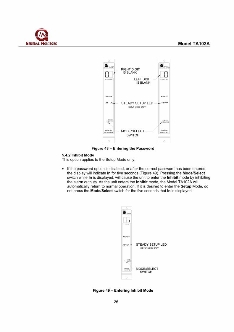
5.4.1 Entering the Password This option applies to the Setup Mode only: • If the password option is enabled, the right digit of the display will be blank and a 0
will appear in the left digit on the display (Figure 48). Press the Mode/Select switch until the first number of your password is displayed, and then wait about five seconds.
• The left digit of the display will then blank out and a 0 will appear in the right digit on
the display (Figure 48). Press the Mode/Select switch until your correct password number is displayed, then wait about five seconds. If the password is correct the unit will proceed to the inhibit option. If the password is incorrect the user will not be able to proceed and the unit will return to the normal operating mode. Once in the operating mode the user may attempt to re-enter the Setup Mode. The factory default password is 00.
Model TA102A
26
TA102A
0 - 100% LEL
SETUP
RIGHT DIGIT
MODE/SELECT
GENERALMONITORS
TA102A
0 - 100% LEL
READY READY
SETUP
SELECTMODE/
MONITORSGENERAL
IS BLANK
LEFT DIGITIS BLANK
STEADY SETUP LED(SETUP MODE ONLY)
MODE/SELECTSWITCH
Figure 48 – Entering the Password
5.4.2 Inhibit Mode This option applies to the Setup Mode only: • If the password option is disabled, or after the correct password has been entered,
the display will indicate In for five seconds (Figure 49). Pressing the Mode/Select switch while In is displayed, will cause the unit to enter the Inhibit mode by inhibiting the alarm outputs. As the unit enters the Inhibit mode, the Model TA102A will automatically return to normal operation. If it is desired to enter the Setup Mode, do not press the Mode/Select switch for the five seconds that In is displayed.
TA102A
0 - 100% LEL
READY
SETUP STEADY SETUP LED(SETUP MODE ONLY)
SELECTMODE/
GENERALMONITORS MODE/SELECT
SWITCH
Figure 49 – Entering Inhibit Mode

Model TA102A
27
5.4.3 A2 Alarm Options Next, the A2 LED will be flashing while the Energized/De-Energized option is displayed (Figure 50). The display will indicate the current selection, (En or dE). Press the Mode/Select Switch to toggle the selection. De-Energized is the factory default for this selection.
TA102A
0 - 100% LEL
SETUP
MODE/SELECT
GENERALMONITORS
TA102A
0 - 100% LEL
READY READY
SETUP
SELECTMODE/
MONITORSGENERAL
SETUP LED
A2 A2FLASHING A2 LED
FLASHING for SETUPCHECK MODE,
STEADY FOR SETUP MODE
Figure 50 – A2 Energized/De-Energized Alarm Option
The A2 LED on the front panel will be flashing while the latching/non-latching option is displayed (Figure 51). The display will indicate the current selection, (nL or LA). Press the Mode/Select Switch to toggle the selection. Latching is the factory default for this selection.
TA102A
0 - 100% LEL
SETUP
MODE/SELECT
GENERALMONITORS
TA102A
0 - 100% LEL
READY READY
SETUP
SELECTMODE/
MONITORSGENERAL
SETUP LED
A2 A2FLASHING A2 LED
FLASHING for SETUPCHECK MODE,
STEADY FOR SETUP MODE
Figure 51 – A2 Latching/Non-Latching Alarm Option

Model TA102A
28
The last A2 alarm option to appear on the display will be the alarm set point (trip level). If this level is reached or exceeded the A2 alarm outputs will activate. The display (Figure 52) will indicate the current A2 alarm set point (10 to 60 in increments of 5). Press the Mode/Select switch repeatedly, until the desired A2 alarm set point appears on the display. 60 is the factory default for this selection.
TA102A
0 - 100% LEL
READY
SETUP SETUP LED
ALARM SETPOINT
A2 FLASHING A2 LED
FLASHING for SETUPCHECK MODE,
STEADY FOR SETUP MODESELECTMODE/
GENERALMONITORS
Figure 52 – A2 Alarm Set Point Option
NOTE - The A2 set point cannot be set lower than the current A1 set point. To accomplish this, you will need to go through Set-up twice. The A1 set point should be set lower than the desired A2 set point, then re-enter the Setup Mode and set the A2 set point.

Model TA102A
29
5.4.4 A1 Alarm Options Next, the A1 LED will be flashing while the Energized/De-energized option is displayed (Figure 53). The display will indicate the current selection, (En or dE). Press the Mode/Select Switch to toggle the selection. De-Energized is the factory default for this selection.
TA102A
0 - 100% LEL
SETUP
MODE/SELECT
GENERALMONITORS
TA102A
0 - 100% LEL
READY READY
SETUP
SELECTMODE/
MONITORSGENERAL
SETUP LED
A1 A1FLASHING A1 LED
FLASHING for SETUPCHECK MODE,
STEADY FOR SETUP MODE
Figure 53 – A1 Energized-De-Energized Alarm Option
The A1 LED on the front panel will be flashing while the latching/non-latching option is displayed (Figure 54). The display will indicate the current selection, (nL or LA). Press the Mode/Select Switch to toggle the selection. Non-Latching is the factory default for this selection.
TA102A
0 - 100% LEL
SETUP
MODE/SELECT
GENERALMONITORS
TA102A
0 - 100% LEL
READY READY
SETUP
SELECTMODE/
MONITORSGENERAL
SETUP LED
A1 A1FLASHING A1 LED
FLASHING for SETUPCHECK MODE,
STEADY FOR SETUP MODE
Figure 54 – A1 Latching/Non-Latching Alarm Option

Model TA102A
30
The last A1 alarm option to appear on the display will be the alarm set point (trip level). If this level is reached or exceeded the A1 alarm outputs will activate. The display will indicate the current A1 alarm set point (Figure 55). Press the Mode/Select switch repeatedly, until the desired A1 alarm set point appears on the display (10 to the A2 set point in increments of 5). The A1 set point cannot be set higher than the A2 set point. 30 is the factory default for this selection.
TA102A
0 - 100% LEL
READY
SETUP SETUP LED
SELECTMODE/
GENERALMONITORS
ALARM SETPOINT
A1 FLASHING A1 LED
FLASHING for SETUPCHECK MODE,
STEADY for SETUP MODE
Figure 55 – A1 Set Point Option
5.4.6 Fault/Inhibit Option Next, the user will select the Fault/Inhibit option. The FAULT LED on the front panel will be flashing while the display indicates Ac or nA (Figure 57). An Ac selection specifies that the Model TA102A will activate the Fault circuit while the unit is in the Inhibit Mode. A nA selection specifies that the Model TA102A will not activate its Fault circuit when the unit is placed in the Inhibit Mode. A nA selection will not disable the Fault circuit, therefore, if a Fault occurs during the Inhibit Mode, the unit will activate the Fault circuit. Not Active is the factory default for this selection.

Model TA102A
31
FAULT FAULTFLASHING FAULT LED
FLASHING for SETUPCHECK MODE,
STEADY FOR SETUP MODE
TA102A
0 - 100% LEL
SETUP
MODE/SELECT
GENERALMONITORS
TA102A
0 - 100% LEL
READY READY
SETUP
SELECTMODE/
MONITORSGENERAL
SETUP LED
Figure 56 – Fault Inhibit Option
Figure 57 – Entering Card Test Options
5.4.7 Card Test Options After the Fault/Inhibit option has been selected, the user will select the ramp time (3 or 10 seconds) and whether or not the alarm outputs will activate during a Card Test. The display will indicate ct for about five seconds (Figure 57) followed by the ramp up time (3 or 10) during the card test (Figure 58). 3 is the factory default for this selection.
FLASHING for SETUPCHECK MODE,
STEADY FOR SETUP MODE
TA102A
0 - 100% LEL
READY
SETUP SETUP LED
SELECTMODE/
GENERALMONITORS
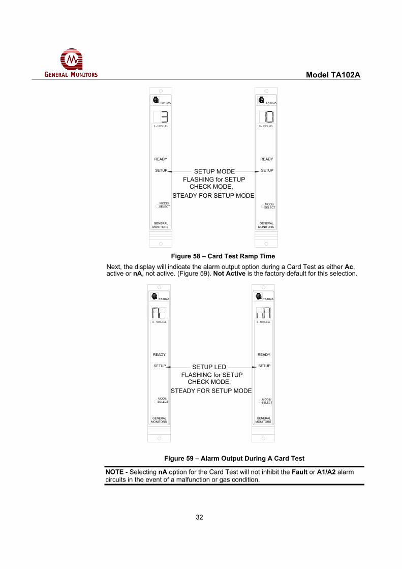
Model TA102A
32
FLASHING for SETUPCHECK MODE,
STEADY FOR SETUP MODE
TA102A
0 - 100% LEL
SETUP
MODE/SELECT
GENERALMONITORS
TA102A
0 - 100% LEL
READY READY
SETUP
SELECTMODE/
MONITORSGENERAL
SETUP MODE
Figure 58 – Card Test Ramp Time
Next, the display will indicate the alarm output option during a Card Test as either Ac, active or nA, not active. (Figure 59). Not Active is the factory default for this selection.
TA102A
0 - 100% LEL
SETUP
MODE/SELECT
GENERALMONITORS
TA102A
0 - 100% LEL
READY READY
SETUP
SELECTMODE/
MONITORSGENERAL
SETUP LEDFLASHING for SETUP
CHECK MODE,STEADY FOR SETUP MODE
Figure 59 – Alarm Output During A Card Test
NOTE - Selecting nA option for the Card Test will not inhibit the Fault or A1/A2 alarm circuits in the event of a malfunction or gas condition.

Model TA102A
33
5.4.8 Password Options Once the Card Test options have been selected, the user will either enable or disable the password option (Figure 60). The display will indicate either PE, for enabled or Pd, for disabled. Password Disabled is the factory default for this selection.
TA102A
0 - 100% LEL
SETUP
MODE/SELECT
GENERALMONITORS
TA102A
0 - 100% LEL
READY READY
SETUP
SELECTMODE/
MONITORSGENERAL
SETUP LEDFLASHING for SETUP
CHECK MODE,STEADY FOR SETUP MODE
Figure 60 – Password Enabled/Disabled Option
This option applies to the Setup Mode only: If the Password is disabled, the unit will return to normal operation. If the Password is enabled, the user will be able to enter a new password (Figure 61). The unit will display the left digit of the existing Password (flashing on the display). The right digit will be blank until the left digit has been selected. Press the Mode/Select switch repeatedly until the desired value is displayed. Once the left digit is correct, wait for five seconds and the right digit of the display will begin flashing and the left digit will be blank. Press the Mode/Select switch repeatedly, until the desired value is displayed. Wait about five seconds and the unit will execute the Setup Check Mode and then return to normal operation. See Section 5.4 for default Password.

Model TA102A
34
TA102A
0 - 100% LEL
SETUP
RIGHT DIGIT
MODE/SELECT
GENERALMONITORS
TA102A
0 - 100% LEL
READY READY
SETUP
SELECTMODE/
MONITORSGENERAL
IS BLANK
LEFT DIGITIS BLANK
STEADY SETUP LED(SETUP MODE ONLY)
MODE/SELECTSWITCH
Figure 61 – Entering A New Password
5.5 Inhibit Mode Whenever the Inhibit Mode is entered, the A1 and A2 alarm outputs are inhibited. The front panel LED’s will still function normally in cases where sufficient gas is present at the sensor. Once this mode has been entered, the user may exit the Inhibit Mode by pressing the Mode/Select Switch. NOTE: - Before exiting Inhibit mode, remove gas from sensor and ensure sensor is seeing clean air i.e. display shows zero. NOTE - Any latched alarms must be reset before exiting the Inhibit Mode. There is a user selectable option that will place the unit in Fault every time the Inhibit Mode is entered. If the user does not select this option, the Fault circuit will function normally during the Inhibit Mode. While the unit is in the Inhibit Mode, the display will indicate IN for 5 seconds, and then the gas concentration will be displayed for 5 seconds. This sequence will repeat for as long as the unit is in the Inhibit Mode. The Inhibit Mode is provided so that the operation of the Model TA102A can be verified without tripping external devices that are connected to the A1 and A2 alarm outputs.

Model TA102A
35
Password Options
5.6 Setup Mode Selection Block Diagram
This section is provided to aid the operator in making selections during the Setup Mode. It is recommended that the operator fill-in the selections in the proper blanks and then use this page as a reference while programming the Model TA102A. The blocks shown below indicate the order of options in the Setup Mode. To the right of each block is a description of the choices that are available for that option. More information about making each selection is provided in Section 5.4.
Enter the Password, if the Password is enabled. Enter the Inhibit Mode, if desired. ENTER SELECTION Set the Energized (En) / De-Energized (dE) Option Set the Latching (LA) / Non-Latching (nL) Option Set the A2 alarm set point (from 10 to 60, in increments of 5) Set the Energized (En) / De-Energized (dE) Option Set the Latching (LA) / Non-Latching (nL) Option Set the A1 alarm set point (from 10 to 60, in increments of 5) The A1 Set Point cannot be higher than the A2 Set Point Set the calibration level, LEL (from 25 to 90, in increments of 1) Set the Fault Activate (Ac) or not (nA) during Inhibit Mode Display will indicate “ct” for 5 seconds Set the ramp time for the Card Test Mode (3 or 10 seconds) Set the Alarm outputs for Active (Ac) or not Active (nA) Set the Password to be Disabled (Pd) or Enabled (PE) If the Password is Enabled:
Set the password digits Left Right After all of the options have been selected, the TA102A will enter the Setup Check Mode.
Password
Inhibit Mode ?
A2 Alarm Options
A1 Alarm Options
CalibrationLevel
Fault/InhibitOptions
Card Test Options
Setup Check Mode

Model TA102A
36
6.0 Appendix
6.1 Principle of Operation General Monitors uses a low temperature catalytic bead to detect the presence of combustible gases and vapors. These gases and vapors are found in many applications. The catalytic bead converts the combustible gases and vapors to heat. This change in heat results in a change in the electrical resistance of the bead. By taking a matched pair of catalytic beads and coating one, so that it does not respond to the presence of combustible gases and vapors, we can compare the change in resistance between the two beads. The bead that is coated is called the reference bead and the other bead is the active bead (Figure 62). Environmental factors can also influence the temperature of the catalytic beads. Because the beads are matched pairs, they will respond to changes in ambient temperature, humidity and pressure equally. By connecting one end of each catalytic bead together, a series circuit is formed. This circuit is supplied with a constant current. The voltage drop across each bead will be identical in the absence of combustible gases and vapors. As combustible material is converted to heat, the resistance across the active bead increases, causing the voltage drop across each bead to be different. This difference is proportional to the amount of combustible gas or vapor that is present at the sensing elements (catalytic beads).
Figure 62 – Catalytic Sensor Diagram

Model TA102A
37
6.2 Applications and Accessories This chapter provides a description of the types of field devices (Smart Sensors, Point IR Detectors) and the accessories, which can be used with the Model TA102A. 6.2.1 Smart Sensors Generally speaking, General Monitors field devices fall into two categories: • Smart Sensors • Point IR Detectors There are different types of General Monitors Smart Sensors. The Model S4100C (figure 63) is a Smart Sensor that was developed for Combustible gas applications. These feature • a 4 to 22mA output that is proportional to the gas concentration at the sensor • they are self contained, • microprocessor controlled, • Hydrocarbon gas monitor with integral 3-digit readout. The Transmitter is connected to the user’s indicating and shut-down equipment by means of a screened and armoured cable. The S4100C is designed to measure and display concentrations of combustible gases in the range of: 0-100% Lower Explosive Level (LEL), but will continue to display concentrations up to 120% LEL.
Figure 63 – S4100C Smart Sensor
The Model S4000C (figure 64) is an Intelligent Sensor for the detection of combustible gases and vapors. The microprocessor-based electronics process information at the sensor site, within an explosion-proof housing. A digital display provides indications and display codes that can be viewed through a window in the cover. A red LED above the digital display signifies an ALARM condition, while a red LED below the digital display signifies a WARN condition. Analog signal (4-20mA) and optional Dual Redundant Modbus communications and relays, provide remote and/or discrete indications of the sensor’s operation. The Model S4000C Intelligent Sensor is rated explosion-proof for use in hazardous areas.

Model TA102A
38
Figure 64 – S4000C Smart Sensor
The detection elements for the General Monitors Smart Sensors include a variety of catalytic Bead Sensors with different detection ranges and sensor bodies: 11159-1L General Purpose, SST, Sintered Steel Arrestor 11159-2L General Purpose, SST, Hi-Temperature, Sintered Steel Arrestor 11159-X Universal Sensor, SST, Sintered Steel Arrestor 10059-1 Industrial, SST, Sintered Steel Arrestor 6.2.2 Point IR Gas Detector General Monitors has developed an alternative field device for combustible gas applications. The Model IR2100 Infrared Point Detector is a microprocessor based hydrocarbon gas detector (figure 65). The General Monitors Model IR2100 is calibrated at the factory and needs no routine field calibration.
The Model IR2100 Infrared Point Detector continuously monitors combustible gases below the Lower Explosion Level (LEL) range* and provides a 4 to 20mA analogue signal proportional to the 0-100% LEL concentration it detects along with a digital RS485 output, allowing unit to be addressable via Modbus Protocol.
Sensor data and status information for the Model IR2100 can be transmitted to a variety of General Monitors’ readout units.
The Model IR2100 Infrared Point Detector operates from a nominal + 24VDC CE marked supply which must be supplied by the customer.

Model TA102A
39
The Model IR2100 may be mounted in a stand alone Junction Box, or Junction Box to ducting via Duct Mounting Plate. A Zero Switch maybe fitted into this Junction Box. The Model IR2100 is available in a number of versions, designed to optimise detection of customer specified gas.
* - or in Methane % by volume range, in which case all references to 0 to 100% LEL should be read as 0 to 100% by volume.
Figure 65 – IR2100 Model
6.2.3 Splash-Guard & TGA-1 General Monitors produces a universal Splash-Guard, P/N 10395-1, that has been designed for use on all General Monitor’s combustible gas and hydrogen sulfide gas sensors (Figure 66). In addition to the Splash-Guard, a Test Gas Applicator (TGA-1) is available for delivering a test gas to remotely located sensors, P/N 10460-2. The Splash-Guard prevents water from rain or equipment wash-downs from being forced into the sensor cavity and affecting the response of the sensing element. Constructed of rugged Valox plastic, it has a series of internal baffles to deflect water down and away from the sensor. This guard (and the TGA-1) is threaded for simple screw-on installation. The Splash-Guard and TGA-1 are recommended for outside applications where rain or frequent hose downs occur, such as offshore platforms.

Model TA102A
40
Figure 66 – Splash-Guard Picture
6.2.4 Dust Guard Assembly The Dust Guard Assembly (Figure 67) is a simple, threaded stainless steel cylinder with a wire- screen at one end. It is easily removed for cleaning and/or replacement of the disposable screen. This General Monitors accessory is specifically designed to prevent dust and particulate matter from reaching the sensor flame arrestor. Such debris can plug the screen and limit the amount of gas reaching the active surface of the sensor.
Figure 67 – Dust Guard Picture
The Dust Guard is also available in a kit with twelve replaceable screens (Figure 68). It can also be used as an effective windscreen, and is recommended for corrosive, windy or high temperature environments.
Figure 68 – Dust Guard Assembly Kit Picture

Model TA102A
41
6.2.5 Duct Mounting Plates General Monitors produces a Duct Mounting Plate (P/N 10041-1 and –2. Dash 2 has a sensor mounted from inside of cover) for applications that require the sensor to be mounted in air-conditioning or heating duct. The Duct Mounting Plate is easy to install (Figure 69).
Figure 69 – Duct Mounting Plate, Assembly Drawing
Read and understand the bulleted list below before mounting the Sensor into a duct. • Select a location on the duct and cut out a hole large enough for the Sensor to be
inserted into the duct. • Place the O-Ring over the Sensor threads, against the 1¼-inch hex on the wiring
side of the sensor. • Insert the wiring side of the Sensor through the Gasket and Cover. • Screw the Lock Nut onto the wiring side of Sensor. • Use the four screws to attach the mounted Sensor to the duct. The Sensor should be
oriented so that when the plate is attached to the duct the sensing element is inside the duct.
The Duct Mounting Plate (P/N 10041) is designed for use with General Monitors Catalytic Bead and MOS Sensors. The Model IR2100 uses the Duct Mounting Plate shown in figure 70.

Model TA102A
42
Figure 70 – IR2100 Duct Mounting Plate

Model TA102A
43
6.2.6 Calibration Equipment The Model TA102A uses a Portable Purge Calibrator (Figure 71) or the 3 Liter Chamber (Figure 71), to accomplish calibration. The calibration and calibration check procedures and use of the Portable Purge Calibrator is explained in Sections 5.2 and 5.3.
Figure 71 – Portable Purge Calibrator
The procedure using the 3-Liter Chamber (Figure 72) is explained below: The 3-Liter Chamber is used when the TA102A is calibrated with liquid or solvent vapors. Before the Model TA102A is calibrated with any solvent or volatile liquid, consult the listing in Appendix B to determine the volume of solvent/liquid required to produce a 50% LEL concentration in the 3-Liter Chamber. However, if the user specified calibration level is not 50% LEL, consult the factory for the correct volume. Let the factory know the calibration level (25 to 90% LEL) and the solvent/liquid being used to calibrate the sensor.
Figure 72 – 3-Liter Chamber

Model TA102A
44
Before using the 3-Liter Chamber, make sure the following are present: 1. 3-Liter Chamber 2. Dish 3. 250 micro-liter syringe 4. Correct volume of solvent/liquid for calibration and calibration checks. • Orient the chamber so that the lid and sensor hole is on top. • After injection onto the evaporation dish, the lid is fastened quickly to contain vapors
in the chamber. • Placing the round General Monitors magnet onto the start switch locating post
operates the fan. • Draw the correct amount of solvent or liquid into the syringe, according to the listing
in Section 6.6. • Place the Model TA102A in the Calibration Check or Calibration Mode, following the
instructions listed in Sections 5.2 and 5.3. 6.2.7 Calibration Check Mode 1. When 0 is flashing on the display (Calibration Check Mode) inject the solvent/liquid
into the dish, reach underneath and behind the fan blades on the inside of the chamber, locate the fan switch; turn it on and close the lid on the 3-Liter Calibration Chamber.
2. As the sensor begins to respond to the combustible vapor in the chamber, the
concentration will begin flashing on the display. 3. The reading will stabilize after one or two minutes. 4. Remove the sensor from the chamber and allow it to see clean air. When the display
has stopped flashing and indicates a few % LEL and then zero (0), the Model TA102A has returned to normal operation.
6.2.8 Calibration Mode: 1. When AC (Calibration Mode) appears on the display, inject the solvent/liquid into the
dish, reach underneath and behind the fan blades on the inside of the chamber, locate the fan switch; turn it on and close the lid on the 3-Liter Calibration Chamber.
2. As the sensor begins to respond to the combustible vapor in the chamber, the
display will indicate CP (Calibration in Progress). 3. After one or two minutes the display will indicate CC (Calibration Complete). 4. Remove the sensor from the chamber and allow it to see clean air. When the display
indicates a few % LEL and then zero (0), the Model TA102A has returned to normal operation.
6.2.9 Calibration Check & Calibration Modes • Remove the Dish from the 3-Liter Chamber and clean thoroughly before using it
again.

Model TA102A
45
6.2.10 Calibration Equipment and Part Numbers 6.2.10.1 Portable Purge Calibrator Assembly:
with 50% LEL Methane Gas 1400150-M with 50% LEL Hydrogen Gas 1400150-H with 50% LEL Ammonia Gas 1400150-A with 50% LEL Butadiene Gas 1400150-BD with 50% LEL Butane Gas 1400150-B with 50% LEL Ethane Gas 1400150-E with 50% LEL Ethylene Gas 1400150-EY with 50% LEL Propane Gas 1400150-P
6.2.10.2 Portable Purge Replacement Cylinder with 50% LEL Methane Gas 1400155-M with 50% LEL Hydrogen Gas 1400155-H with 50% LEL Ammonia Gas 1400155-A with 50% LEL Butadiene Gas 1400155-BD with 50% LEL Butane Gas 1400155-B with 50% LEL Ethane Gas 1400155-E with 50% LEL Ethylene Gas 1400155-EY with 50% LEL Propane Gas 1400155-P
6.2.10.3 Replacement Parts Small Calibration Cup 1400152-1 Large Calibration Cup 1400154
Pressure Gauge Regulator 922-009 Methane Gas 50% LEL 140155-M Hydrogen 50% LEL 140155-H Butadine Gas 50% LEL 140155-BD Butane Gas 50% LEL 140155-B Ethane Gas 50% LEL 140155-E Propane Gas 50% LEL 140155-P
6.2.10.4 Cylinder Refills
50% LEL Methane Gas 140015-M 50% LEL Hydrogen Gas 140015-H 50% LEL Propane Gas 140015-P 50% LEL Butane Gas 140015-B
6.2.10.5 3-Liter Chamber Replacement Parts 3 Liter Chamber with syringe 1400200 Dish for 3 Liter Chamber 928-700 250 microliter syringe 928-718 Motor for 3 Liter Chamber 1400204 Fan for 3 Liter Chamber 1400207

Model TA102A
46
6.3 System Specifications
6.3.1 Application Combustible & Flammable Gas and Vapor Detection. 6.3.2 Sensor Type General Monitors Combustible Gas Smart Sensors or General Monitors Point IR Hydrocarbon Detector. (The latter is not PFG approved). 6.3.3 Typical Sensor Life 3 to 6 years, in normal services for General Monitors PFG approved Catalytic Bead Sensor. 6.3.4 Measuring Range 0 to 100% LEL.
6.3.5 Accuracy The accuracy the TA102A is ± 3% LEL/LFL or 10% of the applied gas, whichever is greater, at reference ambient conditions. 6.3.6 Zero Drift (Card & Sensor*) Less than 5% of span, per year. 6.3.7 Stability (Card & Sensor*) Adheres to FM Class 6310 & Class 6320 and CSA 22.2 No. 152-M1984. Stabilization occurs in approximately two (2) minutes. 6.3.8 Response Time (Card & Sensor* with CH4 gas) T50 < 10 seconds with 100% LEL/LFL concentration of gas applied. T90 < 30 seconds with 100% LEL concentration gas applied. 6.3.9 Storage Place the TA102A in the original storage container that was shipped with the unit. This container guards against contamination from solvents, lubricants, humidity, etc. In the case of long-term storage, the TA102A should be stored as above in a cool, dry, place, preferably between 0 and 20ºC. 6.3.10 Warranty 2 Years
6.4 Mechanical Specifications Weight: 11.2 oz. (318 grams) Length: 9.9 inches (251 mm) Height: 6.825 inches (173 mm) Width: 1 inch (25 mm)

Model TA102A
47
6.5 Electrical Specifications 6.5.1 Input Power Requirement 20 to 35Vdc, (24Vdc @ 250mA, 9W nominal) (300 mA max). PSU noise and ripple voltage 1.0Vpp max. The customer supplied PSU must comply with IEC 1010-1, limiting current to 8A under Fault conditions, in order to comply with CE Marking requirements. NOTE – GM Smart Sensor has max. supply voltage of 30VDC in order to comply with Approval requirements. 6.5.2 Electrical Classification The Model TA102A is designed for use in non-hazardous environments. 6.5.3 Relay Contact Rating 4A @ 30V RMS/42.4V PK, 3A @ 30VDC resistive. DPDT for A1 & A2, SPDT for Fault. 6.5.4 Open Collector Rating 100mA @ 35Vdc for A1, A2, Fault, UA, FUA, CAL-OC, LA1 & LA2. 6.5.5 Cable Parameters Recommended 3-wire screened or screened and armoured per BS5308 Part V, Type 2 or equivalent. Maximum cable lengths allowable between module and the Field Device with 24VDC nominal at the sensor/detector:
mm2 AWG Feet Meters 2.5 14 4500 1372 1.5 16 2250 685 1.0 18 1600 488 .75 20 1100 335 .25 22 750 228
Figure 73 – Recommended Maximum Cable Lengths Between Module & Field Device
The maximum allowable cable lengths between the analog output connections on the control module with a remote device in series (maximum loop resistance of 300 Ohms between Analogue Signal & Common at the Field Device):
mm2 AWG Feet Meters 2.5 14 9000 2740 1.5 16 5200 1585 1.0 18 3800 1160 .75 20 2400 730 .25 22 1600 488
Figure 74 – Maximum Allowable Cable Lengths Between Analog Output Connections On Control Module

Model TA102A
48
6.6 Environmental Specifications 6.6.1 Operating Temperature Range TA102A 0°F to +150°F -18°C to +66°C 6.6.2 Storage Temperature Range TA102A -40°F to +150°F -40°C to +66°C 6.6.3 EMC Susceptibility (EN50082-2 : 1995) 10V/m Max. 6.6.4 Operating Humidity Range 5% to 100% Relative Humidity, non-condensing
Model TA102A
49
6.7 Engineering Specifications 6.7.1 Zero Two System Each system shall utilize modules capable of monitoring gas-sensing elements, or a 0 to 21.7mA analog signal from gas or flame detection transmitters. The system chassis shall be available in 4, 8 and 16 channels. Each chassis shall contain a bus for the following independent signals: • A1 Alarm • A2 Alarm • Fault • Master Reset • Master Accept • Unaccept • CAL • +24Vdc • System Common Module signals shall be capable of being bussed from one chassis to another, so that up to 100 modules can comprise a single system. The gas and flame detection modules shall be electrically and physically compatible and capable of being used in the same chassis to form combined fire and gas detection systems. The system shall consist of Zero Two Series component modules as manufactured by General Monitors, Lake Forest California, U.S.A. or General Monitors, Galway, Ireland. 6.7.2 TA102A Control Module The control module, with sensor, shall meet the performance requirements of CSA 22.2 No. 152-M1984 & FM Classes 6310 & 6320. It shall be capable of monitoring 0 to 100% LEL concentration of combustible gases/vapors. The control module shall have an interface panel, providing a mode/select switch and the following indications: • 2 discrete alarm threshold level indicators • a “fault” or “malfunction” indicator • a “ready” indicator • a calibration mode indicator • a setup mode indicator • a 2 digit digital display All alarm parameters and user options shall be software selectable. A power on self-test (POST) is automatically performed each time the trip amplifier module powers up. A functional card test and a front panel LED test shall be switch capable without interrupting normal on-line services. The control module shall be capable of insertion and removal during power on conditions without damage to any component module in the system. The control module will generate display codes associated with fault conditions whenever a fault or malfunction occurs. A mode/select switch shall provide the operator front panel access to: • a setup check mode • a setup mode • inhibit mode
. The control module shall have a password protected setup routine capable of having the password disabled.

Model TA102A
50
Volatile Liquids and Solvents Volatile liquids and solvents are not supplied by General Monitors. This page provides a listing of volatile liquids and solvents and the respective volumes required (in microliters) to produce a 50% LEL vapor concentration in the 3 Liter Chamber (see Section 6.7). Reference : NFPA 325, 1994 Edition Acetaldehyde............................. 136 Acetic Acid................................. 140 Acetone...................................... 112 Acetonitrile ................................. 96 Acrylonitrile ................................ 120 Amyl Acetate ............................. 100 Amylamine................................. 156 Benzene..................................... 65 Butyl Acetate ............................. 137 Butyl Acrylate............................. 148 Butyl Alcohol .............................. 78 sec-Butyl Alcohol ....................... 95 tert-Butyl Alcohol ....................... 138 Butyl Cellosolve ......................... 88 Butyraldehyde............................ 102 Cyclohexane.............................. 86 Decane ...................................... 95 Diethyl Ketone ........................... 103 Diisobutyl Ketone....................... 82 Dimethylformamide.................... 104 p-Dioxane .................................. 104 Dodecane .................................. 83 Ethyl Alcohol (Ethanol) .............. 118 Ethyl Acetate ............................. 119 Ethyl Amine ............................... 140 Ethyl Benzene ........................... 60 Ethyl Ether ................................. 120 Ethylene Oxide .......................... 89 Gasoline 100 Octane................. 107 Heptane, Normal ....................... 94 Hexane, Normal......................... 86

Model TA102A
51
The volatile liquids and solvents listed in this section are intended for use in the 3-Liter chamber for calibrating General Monitors Catalytic Sensors. Isopentane................................. 99 Isoprene..................................... 89 Isopropyl Alcohol ....................... 93 Isopropyl Ether .......................... 120 JP-4, Jet Fuel ............................ 183 Laktane...................................... 76 Methanol.................................... 148 Methyl Ethyl Ketone (MEK) ....... 76 Methyl Metacrylate .................... 111 Naptha (Petroleum Ether).......... 96 Octane ....................................... 99 Pentane, Normal........................ 105 Propanal (Propionaldehyde)...... 114 2-Propanol (IPA)........................ 93 Propyl Acetate ........................... 106 Propylamine............................... 103 Propylbenzene........................... 68 Propylene Oxide ........................ 98 Styrene ...................................... 63 Tetrahydrofuran ......................... 99 Tetrahydrofurfuryl Alcohol ......... 89 Toluene...................................... 78 Triethylamine ............................. 102 Vinyl Acetate.............................. 152 Vinyl Ethyl Ether ........................ 99 o-Xylene..................................... 67 p-Xylene..................................... 83 Xylenes...................................... 68

Model TA102A
52
6.9 Engineering & Technical Drawings 6.9.1 Outline & Terminal Connections Reference Drawing # 11281-1
Figure 75 – Outline & Terminal Connections

Model TA102A
53
6.9.2 Final Assembly Reference Drawing # 11280-1
TA10
2A
A2 A1 CAL
REA
DY
FAU
LT
SET
UP
0-10
0% L
EL
MO
DE/
SELE
CT
GE
NE
RA
LM
ON
ITO
RS
Figure 76 – Final Assembly

Model TA102A
54
6.10 Zero Two Series Modules Model 2602A Zero Two Series Control Module for Combustible Gas Applications Model TA102A Zero Two Series Trip Amplifier Module for Combustible Gas Applications Model TA202A Zero Two Series Trip Amplifier Module for Hydrogen Sulfide Gas Applications Model TA402A Zero Two Series Trip Amplifier Module for Flame Detection Applications Model TA502A – 3 DIGIT Zero Two Series 3 Digit A flexible multipurpose module for a variety of GM products. Model FM002A Zero Two Series Facilities Module Performs Common Functions for Zero Two Systems Model RL002* Zero Two Series Relay Module Provides Extra Output Capacity for Zero Two Systems Model ZN002A Zero Two Series Zone Control Module Performs Zoning and Voting Functions for Zero Two Systems Model MD002 Zero Two Series Driver Card for Monitoring / Driving High-Current Output Devices Model IN042 Zero Two Series Four Zone Input Card for Callpoints, Smoke & Thermal Detectors Model PS002* Zero Two Series Power Supply Module for Zero Two Systems * = Non-European Countries Only.

Model TA102A
55
Customer Satisfaction Questionnaire
Attention Field Operations: We would appreciate your help in assessing and thus improving the quality of our Equipment and Service and would therefore be grateful if you would complete the Questionnaire below and return it to:
General Monitors Ireland Ltd, Ballybrit Business Park, Galway, Republic of Ireland.
Thank you for your assistance Client ______________________________________________________________________________ Client Order No. ______________________________________________________________________ General Monitors Sales Order No. _______________________________________________________ (Please tick appropriate box) Yes No 1. Was the equipment the correct option? 2. Are sensors correct type and range? 3. Is mechanical assembly good?
(everything proper fit and tight)
4. Did you receive the necessary accessories to commission the equipment?
5. Has the equipment been commissioned? 6. Any problems encountered during commissioning? 7. Is the equipment functioning correctly at present? If you have answered NO to any of the above, please provide further details overleaf. Thank you. Completed by: ________________________________ Date:________________________