manual excicontrol trc - excidor ab ner... · excicontrol contents excicontrol trc control unit 1...
TRANSCRIPT

Manual
ExciControl TRC

ExciControl
Contents ExciControl TRC control unit 1 Introduction Page 1 1.1 System overview 1 2 Safety regulations 2 2.1 General safety regulations 2 2.2 System design regulations 2 3 Installation 3 3.1 Installation instruction 3 3.2 Cable area 3 4 Start-up 4 4.1 Safety at start-up 4 4.2 Before first start-up 4 5 Safety during maintenance
and troubleshooting 4 6 Description of contacts in the control unit 5 6.1 Interface description 5 7 Technical specification 7 7.1 Attachment measures
control unit and display 8 ExciControl TRC Display 8 Menu Structure overview Page 9 9 Description of menues 10 9.1 Operation mode 10 10 Operator 11 10.1 Operator 11 10.2 Copy operator 11 11 Settings 12 11.1 Settings 12 12 Speed 12 12.1 Speed 12 12.2 Speed Rotor 12 12.2 Speed Steering 12 12.2 Speed Grading bucket 12 12.2 Speed Tilt 12 12.2 Speed Extra 12 12.2 Speed Speed 12
13 Ramp Sida 14 13.1 Ramp 14 13.2 Ramp Rotor 14 13.2 Ramp Steering 14 13.2 Ramp Tilt 14 13.2 Ramp Extra 14 14 Calibration joystick 15 14.1 Calibration joystick 15 14.2 Calibration joystick Rotor 15 14.2 Calibration joystick Steering 15 14.2 Calibration joystick Tilt 15 14.2 Calibration joystick Extra 15 14.3 Calibration joystick Dead zone 16 15 Trouble shooting 17 15.1 Trouble shooting 17 15.2 Trouble shooting Digital in 17 15.3 Trouble shooting Digital out 17 15.4 Trouble shooting Analog in 19 15.5 Trouble shooting Analog out 19 16 Basic settings 20 16.1 Basic settings 20 16.2 Basic settings Change side 20 16.3 Basic settings Sort of hydraulic 20 16.4 Basic settings Flow valve factor 21 16.5 Basic settings Digital in left 22 16.5 Basic settings Digital in right 22 16.54.1 Basic settings Digital in 1-5 22 16.6 Basic settings Analog out 24 16.6.1 Basic settings Rotator 24 16.6.1 Basic settings Steering 24 16.6.1 Basic settings Grading bucket 24 16.6.1 Basic settings Tilt 24 16.6.1 Basic settings Extra 24 16.6.1 Basic settings Flow valve 24 16.7 Info 25 Other features 17 Other features 26 17.1 Switch for bucket lock 26 17.2 Automatic switching from tilt rotator to grading hydraulic mode 19 17.3 Relay functions in the control unit 27 17.4 PC software 27 Attachments: System overview and wiring diagram
ExciControl TRC serial .number: 00681-TRC control unit: Rev 02.13 TRC display: Rev 01.02.13, 01.03.01

1
ExciControl TRC serial .number: 00681-TRC control unit: Rev 02.13 TRC display: Rev 01.02.13, 01.03.01
ExciControl TRC control unit
1 Introduction This manual is primarily intended for manufacturer´s design, production and service personnel, but is even intended to be used during maintenance by the user. This manual assumes that the reader has basic l knowledge in handling control and regulating equipment. Sections about safety must be read and understood by anyone who operates or maintains or carrying out interventions in the system's hardware or software. 1.1 System overview

2
ExciControl TRC serial .number: 00681-TRC control unit: Rev 02.13 TRC display: Rev 01.02.13, 01.03.01
2 Safety regulations 2.1 General safety regulations. Work at ExciControl TRC control system may only be carried out by personnel who have good knowledge of the control system, the machine and its safety regulations. Installation, modification, repair and Maintenance must be made according to Excidor´s specifications. Installation, modification, repair and Maintenance is carried out on their own responsibility. The manufacturer is not responsible for accident or incident caused by incorrectly installed or improperly maintenance of the equipment. The manufacturer has no liability if the system is not used in a correct way for the application or if the system functions are used in a way that jeopardize the functioning or safety systems. Damaged materials shall not be used. If the control system proves faulty or damaged wiring or connectors, the system shall not be used until technicians checked the system. Electronic control system in improper installation and in combination with strong electromagnetic interference fields may cause unintentional change of speed on actuated function. Welding works shall be performed before installing the system. If welding must be done after installing the system all the electrical connections must be disconnected from their equipment. Welder cables may never be placed next to electrical wires of the control system. 2.2 Design regulations The system shall be equipped with an emergency switch that breaks the power supply to the control system. The emergency switch must be easily reached from the operating position. The system shall be equipped with a main power switch that turns off the power supply when the control system is not in operating mode. The vehicle must be designed so that the power supply to the control system is cut off when the operator leaves the operating position. The system is EMC tested according to EN 13309:2000.
3
ExciControl TRC serial .number: 00681-TRC control unit: Rev 02.13 TRC display: Rev 01.02.13, 01.03.01
3 Installation
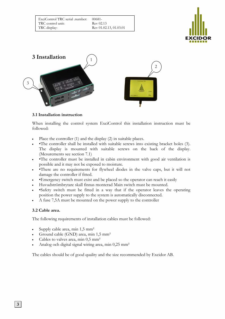
3.1 Installation instruction When installing the control system ExciControl this installation instruction must be followed: • Place the controller (1) and the display (2) in suitable places. • •The controller shall be installed with suitable screws into existing bracket holes (3).
The display is mounted with suitable screws on the back of the display. (Mesurements see section 7.1)
• •The controller must be installed in cabin environment with good air ventilation is possible and it may not be exposed to moisture.
• •There are no requirements for flywheel diodes in the valve caps, but it will not damage the controller if fitted.
• •Emergency switch must exist and be placed so the operator can reach it easily • Huvudströmbrytare skall finnas monterad Main switch must be mounted. • •Safety switch must be fitted in a way that if the operator leaves the operating
position the power supply to the system is automatically disconnected. • A fuse 7,5A must be mounted on the power supply to the controller 3.2 Cable area. The following requirements of installation cables must be followed: • Supply cable area, min 1,5 mm² • Ground cable (GND) area, min 1,5 mm² • Cables to valves area, min 0,5 mm² • Analog och digital signal wiring area, min 0,25 mm² The cables should be of good quality and the size recommended by Excidor AB.
1 2
3

4
ExciControl TRC serial .number: 00681-TRC control unit: Rev 02.13 TRC display: Rev 01.02.13, 01.03.01
4 Start-up 4.1 Safety at start-up The vehicle's engine may not be started until the control system is mounted and its functions have been verified. Make sure nobody is in reaching distance to the vehicle that may be a risk at first start-up. 4.2 Before first start-up Before first start-up following checks must be made: • Check that the controller, display, actuators and cables are correctly installed. • Check that the power supply is correctly installed. • Check the function of the emergency switch. • Make a lever calibration in accordance with section 14. • For all analog outputs that are to be used the speed settings must be made according
to section 12. In this case, before the machine is started, only the settings of ”Min” and ”Max” needs to be done until the indication in the left corner lits up.
• Then, check the output value on the analog outputs. (Section 15.5 troubleshooting analog out). Check that the activated function shows a value (typically about 500-1000 units). If the value shows only a few units the valve is not correctly connected.
• Start the vehicle, pressurize the hydraulic system and turn on the electric power to the
control system. • Check that the hydraulic motions correspond with the levers. • Adjustment of the control system is made using the display.(see instructions in this
manual) 5 Safety during maintenance and troubleshooting Make sure that all following requirements are met before any work with the control system: • The vehicle is turned off. • The vehicle cannot begin to roll. • The hydraulic system is unloaded. • The power supply to the control system is turned off.

5
ExciControl TRC serial .number: 00681-TRC control unit: Rev 02.13 TRC display: Rev 01.02.13, 01.03.01
6 Description of contacts in the controller. The controller has nine contacts and six LED indicators. Each connector and LED indicator has a unique identifier (see sticker on the top of the unit).
6.1 Interface description
HL Inputs from left handle HR Inputs from right handle Molex MicroFit 10-pole Molex MicroFit 10-pole
Pin Function Cable
color/No Pin Function Cable
color/No 1 Rotor analog input White 1 Tilt analog input White
2 Steering analog input Brown 2 Extra A/B analog input Brown
3 Digital input Green 3 Digital input Green
4 Digital input Yellow 4 Digital input Yellow
5 Digital input Gray 5 Digital input Gray
6 Digital input Pink 6 Digital input Pink
7 Digital input Black 7 Digital input Black
8 +5V Violet 8 +5V Violet
9 +10-30V Red 9 +10-30V Red
10 Gnd Blue 10 Gnd Blue
Display Communication display CAN External CanBus Molex MicroFit 4-pole Molex MicroFit 4-pole
Pin Function
Kabel färg/nr Pin Function Cable
color/No 1 Can Low Green 1 Can Low 2 +24 V Red 2 +24 V 3 Gnd Blue 3 Gnd 4 Can high Yellow 4 Can high
LED LED indication (master) LED LED indication (slave)
Color Function Color Function
1 Green, Power ok 4 Green, Power ok 2 Orange, CanBus ok 5 Orange, CanBus ok 3 Red, Error 6 Red, Error

6
ExciControl TRC serial .number: 00681-TRC control unit: Rev 02.13 TRC display: Rev 01.02.13, 01.03.01
6.1 Interface description (continued)
OR Outputs to rotor OM Outputs to machine Molex MiniFit 10-pole Molex MiniFit 16-pole
Pin Function Cable
color/No Pin Function Cable
color/No 1 Rotor left 1 1 Flow valve/Grading bucket left 1 2 Rotor right 2 2 Grading bucket right 3 3 Tilt left 3 3 Grading bucket left 4 Tilt right 4 4 Grading bucket right 5 Extra A 5 5 Steering left 6 Extra B 6 6 Steering right 7 Bucket lock 7 7 Digital 1 8 Ground 8 8 Digital 2 9 Auto switching to grading mode 9 9 Digital 3
10 Auto switching to grading mode 10 10 Digital 4 11 Digital 5
PWR Supply system 12 Digital 6 Molex MiniFit 4-pole 13 Digital 7
Pin Function Cable
color/No 14 Digital 8
1 +10-30VDC Red 15 Ground 2 &
Yellow/Green 2 +10-30VDC Red 16 Ground 3 Ground Blue 4 Ground Blue IM Inputs from machine
Molex MicroFit 6-pole
R Relay functions in/ut Pin Function Cable
color/No Molex MiniFit 12-pole 1 Bucket lock switch to pin 2 Black
Pin Function Cable
color/No 2 Bucket lock switch to pin 1 White
1 Relä 1 IN Black 3 Bucket lock switch to pin 4 Gray
2 Relä 1 OUT Black 4 Bucket lock switch to pin 3 Yellow
3 Relä 2 IN White
5 Summer / Led indication bucket lock
Green
4 Relä 2 OUT White 6 Ground Blue
5 Relä 3 IN Gray 6 Relä 3 OUT Gray 7 Relä 4 IN Yellow 8 Relä 4 OUT Yellow 9 Relä 5 IN Green
10 Relä 5 OUT Green 11 Relä 6 IN Violet 12 Relä 6 OUT Violet

7
ExciControl TRC serial .number: 00681-TRC control unit: Rev 02.13 TRC display: Rev 01.02.13, 01.03.01
7 Technical specification General Specifications Weight 500g Power supply 10-30V Size 169 x 123 x 52 mm Power consumption <200 mA (own consump.) Operating temperature -25°C t0 +65°C CanBus extern J1939 Class of protection IP 32 CanBus display J1939 (modified) Housing Aluminium Current control Yes Voltage control Yes Short-circuit protection Yes Analog inputs Analog outputs Number 4 pcs. Number 11 pcs. Signal range 0-5000 mV Current at 24V 0-3000 mA Active range 200-4800 mV Frequencys Adjustible 60-200 Hz Dead zone Adjustible Min current Adjustible Max load 50 mA Max current Adjustible Ramp time Adjustible Digital inputs Digital outputs Number 18 pcs. Number 0-16 pcs. Signal range 0-30V Current at 24V Max 2A Aktivt range 4–30V Number of relay inuts 6 pcs. Number of relay outputs 6 pcs. Number of pin to pin 3 pcs. Number of pin to pin 3 pcs.

8
ExciControl TRC serial .number: 00681-TRC control unit: Rev 02.13 TRC display: Rev 01.02.13, 01.03.01
7.1 Attachment measures control unit and display Attachment measures control unit. (mm)
Attachment measures display
9
ExciControl TRC serial .number: 00681-TRC control unit: Rev 02.13 TRC display: Rev 01.02.13, 01.03.01
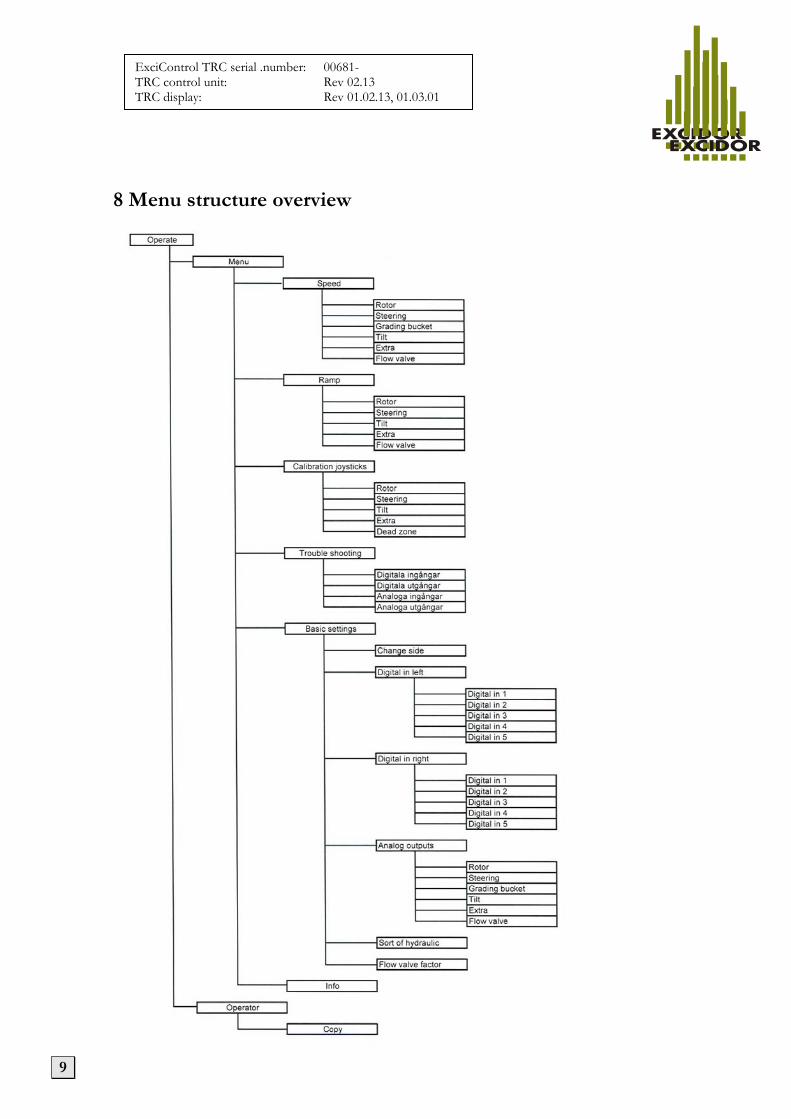
8 Menu structure overview

10
ExciControl TRC serial .number: 00681-TRC control unit: Rev 02.13 TRC display: Rev 01.02.13, 01.03.01
9 Description of menues 9.1 Operating mode
Operating mode is supposed to be the menu used in the operation of the machine. But the control system is also in active mode when you are in the other menus in the system. In operating mode, there are two menu choices, Operator and Menu. By clicking on these buttons will move the system to additional menus and settings. In the lower left corner shows which of the four possible drivers that are active driver. Operator see section 10 Menu see section 11
Red warning triangle is displayed when the bucket lock is open.
Double-arrow to the left shows that the rotor and tilt has shifted side of the right and left grip.
The crossed circle with arrows showing the grading bucket hydraulics is activated.

11
ExciControl TRC serial .number: 00681-TRC control unit: Rev 02.13 TRC display: Rev 01.02.13, 01.03.01
10 Operator 10.1 Operator
In the menu Operator following settings can be done: Change operator switches active operator 1-5. The active operator appear to the right of the button. Change language switches active language and moves between the languages available on your system. Active language appears to the right of the button. Copy button switches to the menu for the copy of a driver's preferences. Note that the parameters of the driver 5 cannot be changed from the display. Driver 5 is the factory settings and can be changed only by a service technician.
10.2 Copy operator
In this menu, a operator's settings are copied to another operator. Copying is always made from the active operator which you set in the previous menu (see paragraph 1.10 Operator). Active operator in the middle of this menu. Choose with the buttons + / - to which the operator settings to be copied (shown at the bottom of this menu). When you made your choice, confirm with Enter button or returns without copying the Resume button. Note that you cannot copy to operator 5 without performing special actions. You can, however, copy from operator 5 to operator 1-4. Only service technicians. To copy to operator 5, the digital output 8 must be activate. Then it is possible to select "5" in the "Copy on operator" box.

12
ExciControl TRC serial .number: 00681-TRC control unit: Rev 02.13 TRC display: Rev 01.02.13, 01.03.01
11 Settings 11.1 Menu/Settings
From the operating mode and choice of button Menu enters this menu Settings. The following pages describe these menus and how the settings are performed. At the beginning of each menu description also shows the way of touch it takes to get to the menu. (e.g. Menu/Speed/Rotor). Speed see section 12 Ramp see section 13 Calibration joystick see section 14 Trouble shooting see section 15 Basic settings see section 16 Info see section 17
12 Speed 12.1 Menu/Speed
The following menus are available in Speed: Click the button for the function you want to adjust rates. Speeds can be adjusted is the Min and Max, where min is the lowest possible speed and max the maximum possible speed. Following pages describe how adjustments are made.
12.2 Menu/Speed/Rotor
The picture on the left side shows the menu for adjusting the speed of the Rotor. Description also applies to Steering, Grading bucket, Tilt, Extra and Flow valve. Choose with the buttons, Max right, Max left, Min right, Min left, the function to be adjusted. The selected function (shown by the indicator to the right of the button) can then be adjusted with the + / - while test-running the function. In this mode, the selected function will not run proportionally. Only min or max value can be activated via the rollers in the handles. The indicator in the upper left shows when reading of the coil is complete. Scanning is done automatically as

13
ExciControl TRC serial .number: 00681-TRC control unit: Rev 02.13 TRC display: Rev 01.02.13, 01.03.01
Min or Max current stabilized at the set minimum or maximum level. Reading of the coil "Min" and coil "Max" must be done at least once during start-up of the system to regulate optimally. Other non-selected functions will work as in operating mode. Confirm by pressing Enter or return by pressing Back.

14
ExciControl TRC serial .number: 00681-TRC control unit: Rev 02.13 TRC display: Rev 01.02.13, 01.03.01
13 Ramp 13.1 Menu/Ramp
The following menus are available in Ramp: Click the button for the function you want to change the ramp times. Ramp times that you can adjust are Start and Stop, where start is a soft start of the function and the stop is a soft stop of the function. Following pages describe how adjustments are made.
13.2 Menu/Ramp/Rotor
The picture on the left side shows the menu for adjusting the Ramp. Description also applies to Steering, Grading bucket, Tilt, Extra and Flow valve. Choose adjust ramp time you choose the button, Start right, Start left, Stop right, Stop left, for the function to be adjusted. The selected function (shown by the indicator to the right of the button) can then be adjusted with the + / - while test-running the function. Other non-selected functions will work as in operating mode. Displayed value to the right of the button is milliseconds (1000 milliseconds = 1 second). Confirm by pressing Enter or return by pressing Back.

15
ExciControl TRC serial .number: 00681-TRC control unit: Rev 02.13 TRC display: Rev 01.02.13, 01.03.01
14 Calibration joystick 14.1 Menu/Calibration joystick
The following menus are available in the Calibration joysticks: Calibration can / must be performed on all analog (proportional) signals to the controller. The calibration is for the system to know the function's center position (unaffected) and max position in both directions. Click the button for the function you want to calibrate. Following pages describe how to make the calibrations.
14.2 Menu/Calibration joystick/Rotor
The picture on the left side shows the menu for calibrating Rotor. Description also applies to Steering, Tilt and Extra. Next to the text Joystick value the value is displayed in millivolts (2500mV = 2.5 V). The value shall in unaffected position be 2500 + / - 100. In the end positions of the rollers the value should be about 500 at Min in and 4500 at Max in. The value in the upper left corner show the internal calibrated value. When the joystick is properly calibrated, the value is 2000 at the maximum stroke and -2000 at minimum. The neutral value is 0. Setup is as follows: In unaffected position click on the Neutral. Thereafter, with the function is fully affected, you first click Max in and then in the opposite direction Min in. Confirm with Save or Cancel to return.

16
ExciControl TRC serial .number: 00681-TRC control unit: Rev 02.13 TRC display: Rev 01.02.13, 01.03.01
14.3 Menu/ Calibration joystick /Dead zone
Dead zone function is used to create an area from the function inactivated position (center position) where the system thinks that you are not yet touched the function. The setting is adjusted as a percentage (%). To adjust the dead zone on each function, select the first button to the left of the function to be adjusted. The selected function (shown by the indicator to the right of the button) can then be adjusted by + / - buttons. Confirm with Save or Cancel to return.

17
ExciControl TRC serial .number: 00681-TRC control unit: Rev 02.13 TRC display: Rev 01.02.13, 01.03.01
15 Trouble shooting 15.1 Menu/Troubleshooting
The following menus are available in Troubleshooting:
15.2 Menu/Troubleshooting/Digital inputs
The digital inputs that can be debugged using the system shown in this menu. In front of each function is a box that lights up when the input is active. If the box for the selected function is not lit up, the most likely error is that the supply to the key or the signal from the key has been lost or that the key is broken. Check the cable from the connector HL for the left handle or HR for the right handle. Which number in the contact or wire color of cable is found in the interface description section 6.1
15.3 Menu/ Troubleshooting/Digital outputs
Relay and digital outputs that can be checked using the system shown in this menu. In front of each function is a box that lights up when output is active If the box for the selected function is not lit, the likely error is that the key input is not working (see section 19.2) If the box appears but the function still is not working it is probably cable from the connector R, OM or OR that is broken. Which number in the contact or wire color of cable is found in the interface description section 6.1. R1-R6 shows status of relay outputs. Out 1-Out 8 visar status på digitala utgångar.

18
ExciControl TRC serial .number: 00681-TRC control unit: Rev 02.13 TRC display: Rev 01.02.13, 01.03.01
15.4 Menu/ Troubleshooting/Analog inputs
The analog inputs that can be checked using this controll system is shown in this menu. Next to each function the value is displayedFramför varje funktion visas aktuellt värde för respektive analog ingång. It is shown in millivolts (2500mV = 2,5V). The value shall in unaffected position be 2500 + / - 100. In the end positions of the rollers the value should be about 500 at Min in and 4500 at Max in. If the values are incorrect the most likely reasons are that the cables for the supply or ground to the lever/roller is disconnected or that the roller is broken. Check the cable from the connector HL for the left handle or HR for the right handle. Which number in the contact or wire color of cable is found in the interface description section 6.1
15.5 Menu/ Troubleshooting/Analog outputs
The analog inputs that can be checked using this controll system is shown in this menu. On the left side of each function a box lts up when the outout signal is active. Next to the box the value is displayed in milliampere (1000mA = 1A). In normal operation, the color is green. If there is a short circuit the color turns red when activated. If the output cable is cut off or not connected (open circuit) the color turns yellow. Check the cables from connector OM or OR . Which number in the contact or wire color of cable is found in the interface description section 6.1 If the indication box for a function doesn´t lit up at all, check the digital or analog input. see section 15.2 and 15.4).

19
ExciControl TRC serial .number: 00681-TRC control unit: Rev 02.13 TRC display: Rev 01.02.13, 01.03.01
16 Basic Settings 16.1 Menu/Basic settings
The following menus are available in Basic settings.
16.2 Menu/Basic settings/Change side
This menu allows you to, for active operator, chage sides, from the left handle to the right handle on the Rotor and tilt as well as for Grading bucket. If the change side feature is active the indication box turns red and a dubble-arrow symbol is visible on the operation mode menue. See section 9.1
16.3 Menu/ Basic settings /Sort of hydraulic
There are three predefined applications in the system that can be used depending on the configuration of the hydraulic system on the machine and tilt-rotator. Select the hydraulic system by clicking on the Sort 1, Sort 2 or Sort 3 button. Note that the choice of hydraulic systems affect the other settings in the system being possible or not possible to make. For example, when selection of the Sort 1 is made no settings of analog outputs for the tilt-rotator is possible. If Sort 2 is selected no analog settings of the Flow valve is possible.

20
ExciControl TRC serial .number: 00681-TRC control unit: Rev 02.13 TRC display: Rev 01.02.13, 01.03.01
16.4 Menu/Basic settings/Flow valve factor
In this menu you can choose the extra output value of the flow valve when two functions are run simultaneously The range is 100 – 120 %.
21
ExciControl TRC serial .number: 00681-TRC control unit: Rev 02.13 TRC display: Rev 01.02.13, 01.03.01
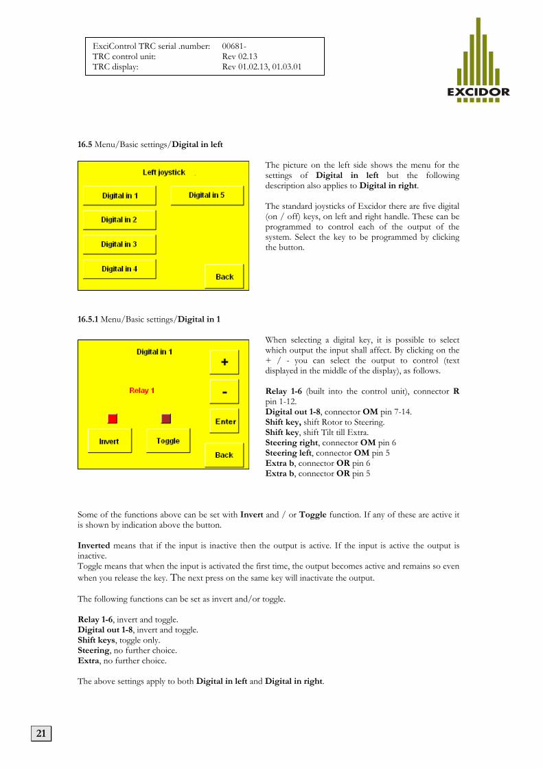
16.5 Menu/Basic settings/Digital in left
The picture on the left side shows the menu for the settings of Digital in left but the following description also applies to Digital in right. The standard joysticks of Excidor there are five digital (on / off) keys, on left and right handle. These can be programmed to control each of the output of the system. Select the key to be programmed by clicking the button.
16.5.1 Menu/Basic settings/Digital in 1
When selecting a digital key, it is possible to select which output the input shall affect. By clicking on the + / - you can select the output to control (text displayed in the middle of the display), as follows. Relay 1-6 (built into the control unit), connector R pin 1-12. Digital out 1-8, connector OM pin 7-14. Shift key, shift Rotor to Steering. Shift key, shift Tilt till Extra. Steering right, connector OM pin 6 Steering left, connector OM pin 5 Extra b, connector OR pin 6 Extra b, connector OR pin 5
Some of the functions above can be set with Invert and / or Toggle function. If any of these are active it is shown by indication above the button. Inverted means that if the input is inactive then the output is active. If the input is active the output is inactive. Toggle means that when the input is activated the first time, the output becomes active and remains so even when you release the key. The next press on the same key will inactivate the output. The following functions can be set as invert and/or toggle. Relay 1-6, invert and toggle. Digital out 1-8, invert and toggle. Shift keys, toggle only. Steering, no further choice. Extra, no further choice. The above settings apply to both Digital in left and Digital in right.

22
ExciControl TRC serial .number: 00681-TRC control unit: Rev 02.13 TRC display: Rev 01.02.13, 01.03.01
16.6 Menu/Basic settings/Analog outputs
I meny till vänster visas de analoga utgångar som finns tillgängliga i systemet. Välj önskad funktion genom att klicka på respektive knapp.
16.6.1 Menu/ Basic settings /Analog outputs/Rotor
To the left setting for Rotator. The following settings apply to all the analog outputs of the system (except Flow valve that don’t have the button Invert). Select the function to be changed by clicking on the respective button. Active function is shown by the box to the right of the button lights up. Frequency is adjustable ripple which causes the valve to vibrate and not get caught in its stationary position. The frequency is adjustable between 60-200 Hz and the normal value is 100Hz (see the valve manufacturer's specification for the correct value). Amplitude is an adjustable pulse duration of the current controlled output. The amplitude is adjustable between 0-30% and the normal value is 10% (see the valve manufacturer's specification for the correct value).. Invert means that the output function, contrary to normal function. That is, if the input is unaffected output is active and provides the setting value of max. When the input then increases the output will decrease.

23
ExciControl TRC serial .number: 00681-TRC control unit: Rev 02.13 TRC display: Rev 01.02.13, 01.03.01
16.7 Menu/Info
The menu Info displays the current serial number and software version of the system. Serial number on the master and slave to the two circuit boards that are mounted inside the controller. In the lower half shows what software versions that each unit is loaded with. When contacting a technician, this information can be useful to have available so the technician knows what version of ExciControl TRC that you have.

24
ExciControl TRC serial .number: 00681-TRC control unit: Rev 02.13 TRC display: Rev 01.02.13, 01.03.01
17 Other features 17.1 Switch for Bucket lock. To change buckets in the bucket attachment on the tilt rotator is required in the control system ExciControl TRC requires that switch for bucket lock is plugged in (included in kit). This switch is connected to the IM contacts in the controller (see section 6.1) with double safety through 2 parallel pin to pin connections. This means that the activation of bucket lock requires that both pins 1 and 2 and pins 3 and 4 in the IM contacts are connected to make it possible to loosen the bucket from the rotor. In the same connector, it is also possible that in pin 5 and 6 connect a light indicator or warning buzzer. When the bucket lock is open, a warning triangle in the operating mode is visible in the display (see section 9.1). 17.2 Automatic switching from tiltrotator to grading hydraulic mode. The control system ExciControl TRC has the ability to combine function for rotor tilt and grading bucket hydraulics. With the tilt-rotator attached the rollers in the handles control each rotor and tilt functions by activating the output pin 1-4 in contact OR of the controller (see section 6.1). The hydraulic oil flow from the machine is automatically activated and controlled by the output pin 1 (Flow valve) in connector OM (see section 6.1). With tilt-rotator disconnected and the lid (included in kit) mounted in connector (the same connector as the tilt-rotator is connected to) pin 9 and 10 is fed back in the controller connector OR (see section 6.1). This then leads to that the handle rollers now instead of controlling only pin 1 (Flow valve) in contact OM alone control pins 1 and 2 in contact OM which then can be used for the machine's grading bucket hydraulic. For automated access to the machine bucket lock function, see Section 17.3.
25
ExciControl TRC serial .number: 00681-TRC control unit: Rev 02.13 TRC display: Rev 01.02.13, 01.03.01
17.3 Relay functions in the control unit. In connector R in the controller (see section 6.1) is the possibility of six individual relay functions. These are intended to be used instead of loosely mounted relays that would otherwise occur at other installations on different machines. These relay functions can then, via the display, be programmed to be controlled by buttons in the handles (see Section 16.4.1). If, for example, a function of the machine, which already is minus controlled by a switch in the original grips, these two wires can instead be connected to pins 1 and 2 of the connector R and then controlled from a key in the new handles. Note that the relay No. 6, pins 11-12 of connector R (see section 6.1) has a special function for the machine bucket lock function. If no key is programmed to control the relay No. 6 (see Section 16.4.1), then the machine bucket lock function can be connected via the relay, pin 11-12. With the tilt-rotator attached the machine bucket lock connection will be disconnected by this relay. With tilt-rotator disconnected and the lid (included in kit) mounted in connector (the same connector as the tilt-rotator is connected to) pin 9 and 10 is fed back in the controller connector OR and relay 6 will (see section 6.1). and relay 6 is closed the machine bucket lock is possible to activate. 17.4 PC-software. When using the PC software instead of the display it is also possible to save settings to file and to read from file to the control system. It is also possible to make adjustments on the 5th operator (default setting). The software is available for download from Excidors website. To use the program a Kvaser dongle is needed (USB-CAN)