manual for differential pressure transmitter
TRANSCRIPT

Please read this manual careful ly before using the product
Pressure / Differential Pressure Transmitter V1.1 Version Manual
PrefaceDear Users:Hello, sincerely thank you for using our products. In order to ensure yousafely, reliably, accuratly use the products, please read the manualcarefully before you use product.This product manual detailedly introduces product technical parameters,application, equipment composition and operation, etc.In order to permanently ensure the reliability and stability of this seriesinstrument, please read the manual carefully before you use product.You will have some new discovery and more practical using methods whenyou are actually operating the instrument, you have a particular opinion forthe shape of the product, the structure and function. Looking forward toyour valuable advice.We will put your ideas into power to improve products, improve the service.Thanks for Your Cooperation!
Table of Contents
1. Safety Precautions .................................. 2
2. Overview ............................................ 2
3. Working principle ................................... 2
4. Common product types ................................ 3
5. Technical parameters ................................ 3
6. Wiring instructions . ................................. 4
................................... 67. Installation type
8. Installation requirements ........................... 7
9. Product Usage ....................................... 8
10. Exception handling ................................. 9
11. Simulation board key debugg ing and operation method .... 10
12. Smart board cassette with HART operation method .....................13
13. Out of the box and check .......................... 16
14. Precautions ........................................ 16
15. Warranty ............................................ 16
-4-
Pressure / differential pressure transmitter
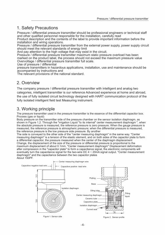
Figure 1. Sensor side
Center measuring diaphragm wire
Capacitive positive lead wire
Isolation diaphragm
Potting
Filling liquid
Curved seat
Figure 2. Sensor profile
1. Safety Precautions
2. Overview
3. Working principle
Pressure / differential pressure transmitter should be professional engineers or technical staff and other qualified personnel responsible for the installation, carefully readProduct description and the contents of the label to provide important information before the installation and wiring operations.Pressure / differential pressure transmitter from the external power supply, power supply circuit should meet the relevant standards of energy limitAnd pay attention to the high voltage that may exist in the circuit.Pressure / differential pressure transmitter maximum static pressure overload has been marked on the product label, the process should not exceed the maximum pressure valueOvervoltage / differential pressure transmitter full scale.Use of pressure / differential pressure transmitters in hazardous applications, installation, use and maintenance should be accompanied by instructions andThe relevant provisions of the national standard.
The company pressure / differential pressure transmitter with intelligent and analog two categories, intelligent transmitter is our reference Advanced experience at home and abroad, the use of fully isolated circuit technology designed with HART communication protocol of the fully isolated intelligent field test Measuring instrument.
The pressure transmitter used in the pressure transmitter is the essence of the differential capacitor box. Process (gas or liquid)Body pressure on the transmitter side of the pressure chamber on the sensor isolation diaphragm, as shown in Figure 1,2. Through the "irrigation Liquid "to its internal" center measurement diaphragm ", when the absolute pressure is measured, the reference pressure is zero pressure; When the gauge pressure is measured, the reference pressure is atmospheric pressure; when the differential pressure is measured, the reference pressure is the low pressure side pressure. By anotherThe side is conveyed to the other side of the "center measuring diaphragm" in the same way. "Center measuring diaphragm" is a tension of the elastic element, and on both sides of the capacitor plate to form a differential capacitor, the pressure measured when the center of the diaphragm displacementChange, the displacement of the size of the pressure or differential pressure is proportional to the maximum displacement of about 0.1mm. "Center measurement diaphragm" Displacement deformation after compression in the "capacitor plate" to form a capacitance signal, the electronic components will eventually turn the capacitance signal for the two-wire DC 4 ~ 20mA signal output. "Center measurement diaphragm" and the capacitance between the two capacitor platesAbout 150PF.
Capacitive negative lead wire
Base
Oiling tube
Center measuring diaphragm
Ceramic tubeCapacitive plate
Isolation diaphragm
-5-
Pressure / differential pressure transmitter
4. Common product types
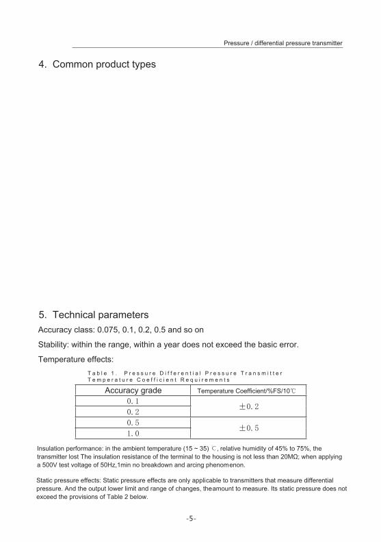
5. Technical parametersAccuracy class: 0.075, 0.1, 0.2, 0.5 and so on
Stability: within the range, within a year does not exceed the basic error.
Temperature effects:T a b l e 1 . P r e s s u r e D i f f e r e n t i a l P r e s s u r e T r a n s m i t t e r T e m p e r a t u r e C o e f f i c i e n t R e q u i r e m e n t s
Accuracy grade Temperature Coefficient/%FS/10℃
0.1±0.2
0.2
0.5±0.5
1.0
Insulation performance: in the ambient temperature (15 ~ 35) ℃, relative humidity of 45% to 75%, the transmitter lost The insulation resistance of the terminal to the housing is not less than 20MΩ; when applying a 500V test voltage of 50Hz,1min no breakdown and arcing phenomenon.
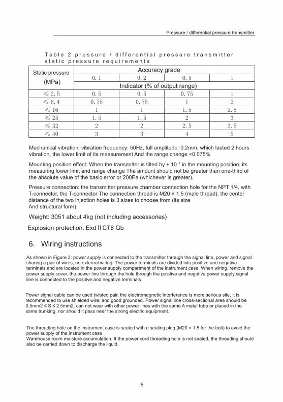
Static pressure effects: Static pressure effects are only applicable to transmitters that measure differential pressure. And the output lower limit and range of changes, the amount to measure. Its static pressure does not exceed the provisions of Table 2 below.
-6-
Pressure / differential pressure transmitter
T a b l e 2 p r e s s u r e / d i f f e r e n t i a l p r e s s u r e t r a n s m i t t e r s t a t i c p r e s s u r e r e q u i r e m e n t s
Static pressure
(MPa)
Accuracy grade0.1 0.2 0.5 1
Indicator (% of output range)≤ 2.5 0.5 0.5 0.75 1
≤ 6.4 0.75 0.75 1 2
≤ 16 1 1 1.5 2.5
≤ 25 1.5 1.5 2 3
≤ 32 2 2 2.5 3.5
≤ 40 3 3 4 5
Weight: 3051 about 4kg (not including accessories)
Explosion protection: ExdⅡCT6 Gb
6. Wiring instructions
Mechanical vibration: vibration frequency: 50Hz, full amplitude: 0.2mm, which lasted 2 hours vibration, the lower limit of its measurement And the range change <0.075%
Mounting position effect: When the transmitter is tilted by ± 10 ° in the mounting position, its measuring lower limit and range change The amount should not be greater than one-third of the absolute value of the basic error or 200Pa (whichever is greater).
Pressure connection: the transmitter pressure chamber connection hole for the NPT 1/4, with T-connector, the T-connector The connection thread is M20 × 1.5 (male thread), the center distance of the two injection holes is 3 sizes to choose from (its sizeAnd structural form).
As shown in Figure 3: power supply is connected to the transmitter through the signal line, power and signal sharing a pair of wires, no external wiring. The power terminals are divided into positive and negative terminals and are located in the power supply compartment of the instrument case. When wiring, remove the power supply cover, the power line through the hole through the positive and negative power supply signal line is connected to the positive and negative terminals
Power signal cable can be used twisted pair, the electromagnetic interference is more serious site, it is recommended to use shielded wire, and good grounded. Power signal line cross-sectional area should be 0.5mm2 ≤ S ≤ 2.5mm2, can not wear with other power lines with the same A metal tube or placed in the same trunking, nor should it pass near the strong electric equipment.
The threading hole on the instrument case is sealed with a sealing plug (M20 × 1.5 for the bolt) to avoid the power supply of the instrument caseWarehouse room moisture accumulation. If the power cord threading hole is not sealed, the threading should also be carried down to discharge the liquid.

-7-
Figure 4 power supply voltage and load resistance
36
920690
Load resistance RL Calculation formula:
RL= (Vs-12)/0.026 (Ω)
RL - Load resistance
Vs - Power supply pressure
HART communication, power supply
The range is (18.5 ~36) VDC
460
250
Pressure / differential pressure transmitter
Figure 3 Transmitter field wiring
Power supply loadSince the HART digital communication signal is superimposed on the loop (4 to 20) mA, the "HART Communicator" must pass The "load resistance" in series on the loop can send or receive HART digital communication signals. To make the power supply and Communication work, "load resistance" of the resistance to be in a certain range, it is recommended to use 250Ω. Power supply Pressure and the "load resistance" relationship shown in Figure 4:
Pressure/ differential pressure transmitter
Logger
Power supply
Milliampere table
Hart Communicator Indicator
Load Resistance
Working area
Power supply
-8-
Pressure / differential pressure transmitter
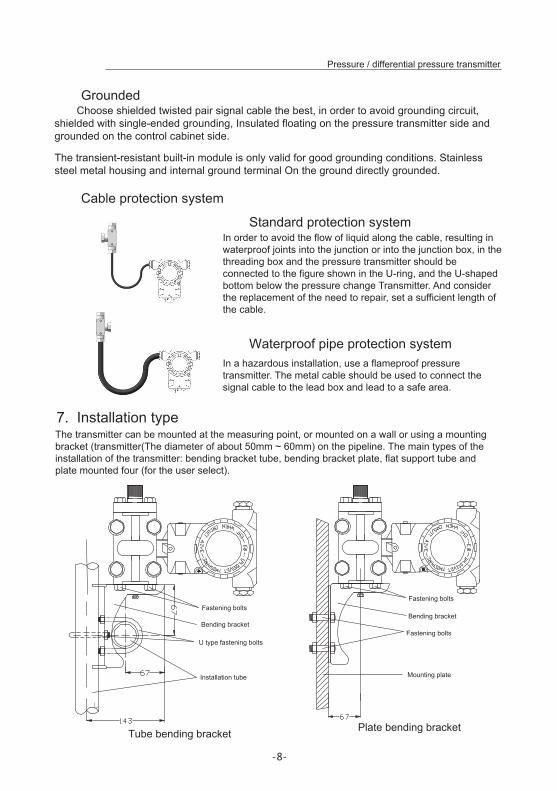
7. Installation type
Standard protection system
Cable protection system
Waterproof pipe protection system
Grounded
Tube bending bracket Plate bending bracket
Choose shielded twisted pair signal cable the best, in order to avoid grounding circuit, shielded with single-ended grounding, Insulated floating on the pressure transmitter side and grounded on the control cabinet side.
The transient-resistant built-in module is only valid for good grounding conditions. Stainless steel metal housing and internal ground terminal On the ground directly grounded.
In order to avoid the flow of liquid along the cable, resulting in waterproof joints into the junction or into the junction box, in the threading box and the pressure transmitter should be connected to the figure shown in the U-ring, and the U-shaped bottom below the pressure change Transmitter. And consider the replacement of the need to repair, set a sufficient length of the cable.
In a hazardous installation, use a flameproof pressure transmitter. The metal cable should be used to connect the signal cable to the lead box and lead to a safe area.
The transmitter can be mounted at the measuring point, or mounted on a wall or using a mounting bracket (transmitter(The diameter of about 50mm ~ 60mm) on the pipeline. The main types of the installation of the transmitter: bending bracket tube, bending bracket plate, flat support tube and plate mounted four (for the user select).
Fastening bolts
Bending bracket
U type fastening bolts
Installation tube
Fastening bolts
Bending bracket
Fastening bolts
Mounting plate
-9-
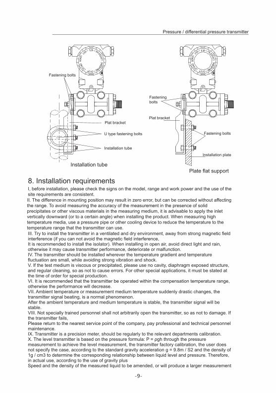
8. Installation requirements
Installation tubePlate flat support
Fastening bolts
Fastening bolts
Installation plate
I, before installation, please check the signs on the model, range and work power and the use of the site requirements are consistent.
Fastening bolts
Plat bracket
U type fastening bolts
Installation tube
Plat bracket
II. The difference in mounting position may result in zero error, but can be corrected without affecting the range. To avoid measuring the accuracy of the measurement in the presence of solid precipitates or other viscous materials in the measuring medium, it is advisable to apply the inlet vertically downward (or to a certain angle) when installing the product. When measuring high temperature media, use a pressure pipe or other cooling device to reduce the temperature to the temperature range that the transmitter can use.III. Try to install the transmitter in a ventilated and dry environment, away from strong magnetic field interference (if you can not avoid the magnetic field interference,It is recommended to install the isolator). When installing in open air, avoid direct light and rain, otherwise it may cause transmitter performance, deteriorate or malfunction.IV. The transmitter should be installed wherever the temperature gradient and temperature fluctuation are small, while avoiding strong vibration and shock.V. If the test medium is viscous or precipitated, please use no cavity, diaphragm exposed structure, and regular cleaning, so as not to cause errors. For other special applications, it must be stated at the time of order for special production.VI. It is recommended that the transmitter be operated within the compensation temperature range, otherwise the performance will decrease.VII. Ambient temperature or measurement medium temperature suddenly drastic changes, the transmitter signal beating, is a normal phenomenon.After the ambient temperature and medium temperature is stable, the transmitter signal will be stable.VIII. Not specially trained personnel shall not arbitrarily open the transmitter, so as not to damage. If the transmitter fails,Please return to the nearest service point of the company, pay professional and technical personnel maintenance.IX. Transmitter is a precision meter, should be regularly to the relevant departments calibration.X. The level transmitter is based on the pressure formula: P = ρgh through the pressure measurement to achieve the level measurement, the transmitter factory calibration, the user does not specify the case, according to the standard gravity acceleration g = 9.8m / S2 and the density of 1g / cm3 to determine the corresponding relationship between liquid level and pressure. Therefore, in actual use, according to the use of gravity plusSpeed and the density of the measured liquid to be amended, or will produce a larger measurement
Pressure / differential pressure transmitter
-10-
Pressure / differential pressure transmitter
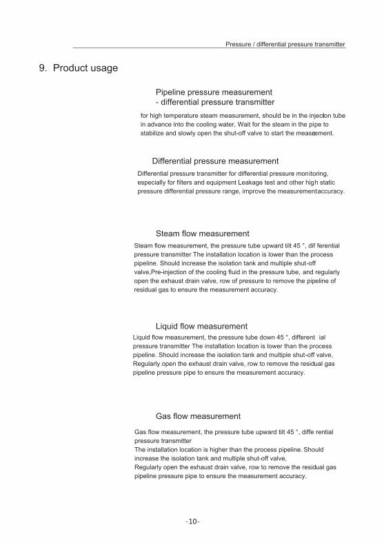
Liquid flow measurement
Gas flow measurement
Pipeline pressure measurement - differential pressure transmitter
Differential pressure measurement
Steam flow measurement
9. Product usage
for high temperature steam measurement, should be in the injection tube in advance into the cooling water, Wait for the steam in the pipe to stabilize and slowly open the shut-off valve to start the measurement.
Differential pressure transmitter for differential pressure monitoring, especially for filters and equipment Leakage test and other high static pressure differential pressure range, improve the measurement accuracy.
Steam flow measurement, the pressure tube upward tilt 45 °, dif ferential pressure transmitter The installation location is lower than the process pipeline. Should increase the isolation tank and multiple shut-off valve,Pre-injection of the cooling fluid in the pressure tube, and regularly open the exhaust drain valve, row of pressure to remove the pipeline of residual gas to ensure the measurement accuracy.
Liquid flow measurement, the pressure tube down 45 °, different ial pressure transmitter The installation location is lower than the process pipeline. Should increase the isolation tank and multiple shut-off valve,Regularly open the exhaust drain valve, row to remove the residual gas pipeline pressure pipe to ensure the measurement accuracy.
Gas flow measurement, the pressure tube upward tilt 45 °, diffe rential pressure transmitterThe installation location is higher than the process pipeline. Should increase the isolation tank and multiple shut-off valve,Regularly open the exhaust drain valve, row to remove the residual gas pipeline pressure pipe to ensure the measurement accuracy.
-11-
Pressure / differential pressure transmitter
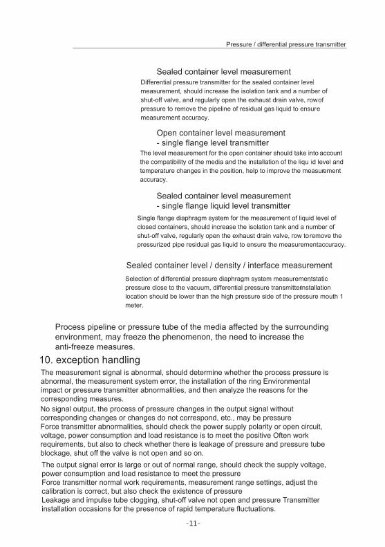
Sealed container level measurement
Open container level measurement - single flange level transmitter
Sealed container level measurement - single flange liquid level transmitter
Sealed container level / density / interface measurement
10. exception handling
Differential pressure transmitter for the sealed container level measurement, should increase the isolation tank and a number of shut-off valve, and regularly open the exhaust drain valve, row of pressure to remove the pipeline of residual gas liquid to ensure measurement accuracy.
The level measurement for the open container should take into account the compatibility of the media and the installation of the liqu id level and temperature changes in the position, help to improve the measurement accuracy.
Single flange diaphragm system for the measurement of liquid level of closed containers, should increase the isolation tank and a number of shut-off valve, regularly open the exhaust drain valve, row to remove the pressurized pipe residual gas liquid to ensure the measurement accuracy.
Selection of differential pressure diaphragm system measurement, static pressure close to the vacuum, differential pressure transmitter installation location should be lower than the high pressure side of the pressure mouth 1 meter.
Process pipeline or pressure tube of the media affected by the surrounding environment, may freeze the phenomenon, the need to increase the anti-freeze measures.
The measurement signal is abnormal, should determine whether the process pressure is abnormal, the measurement system error, the installation of the ring Environmental impact or pressure transmitter abnormalities, and then analyze the reasons for the corresponding measures.No signal output, the process of pressure changes in the output signal without corresponding changes or changes do not correspond, etc., may be pressureForce transmitter abnormalities, should check the power supply polarity or open circuit, voltage, power consumption and load resistance is to meet the positive Often work requirements, but also to check whether there is leakage of pressure and pressure tube blockage, shut off the valve is not open and so on.The output signal error is large or out of normal range, should check the supply voltage, power consumption and load resistance to meet the pressureForce transmitter normal work requirements, measurement range settings, adjust the calibration is correct, but also check the existence of pressureLeakage and impulse tube clogging, shut-off valve not open and pressure Transmitter installation occasions for the presence of rapid temperature fluctuations.

-12-
Pressure / differential pressure transmitter
I. OverviewNo LCD Module Board Panel Figure 1
II. no liquid crystal display module transmitter key operation
II.1 zero clearing
II.2 Lower limit calibration (zero active migration)
II.3 Upper limit calibration (full point calibration)
III. There is a liquid crystal display module transmitter key operation
Figure1 Figure2
Liquid crystal display module panel Figure 2
11. simulation board key debugging and operation methods
When the transmitter with a liquid crystal display module, the transmitter can not only achieve the operation described in 2, you can also use the LCD module comes with three buttons to achieve the parameters of the transmitter configuration, press the button to see Figure 2 As shown.Note: If the transmitter parameters can not be modified, please modify the menu item "write protection" to "off" (specific operation can beRefer to the menu structure).
When the transmitter without liquid crystal display module, the use of the circuit board comes with the keys S and Z (shown in Figure 1) can do the following.
To ensure that the transmitter is in the power state and in a zero pressure state, while holding down the S button and Z button for more than 5 seconds, and then release the two buttons at the same time again press and hold the two keys to maintain about 3 seconds, the transmitter will be the current The pressure value is cleared.
To ensure that the transmitter is in the power state and in the range of the lower limit of pressure state, while holding down the S button and Z button for more than 5 seconds, and then release the two buttons at the same time, hold down the Z button for about 3 seconds, the transmitter current pressure as the range Lower limit, but the transmitter range does not change. For example: the transmitter range of 0-5kPa, the current pressure of -1kPa, when the implementation of this operation, the transmitter range becomes -1-4kPa.
To ensure that the transmitter is in the power state and in the range of the upper limit of pressure state, while holding down the S button and Z button for more than 5 seconds, and then release the two buttons at the same time, hold down the S button for about 3 seconds, the transmitter current pressure as the range The upper limit of the range of the transmitter does not change. For example: the transmitter range of 0-5kPa, the current pressure of 4kPa, when the implementation of this operation, the transmitter range becomes 0-4kPa.
-13-
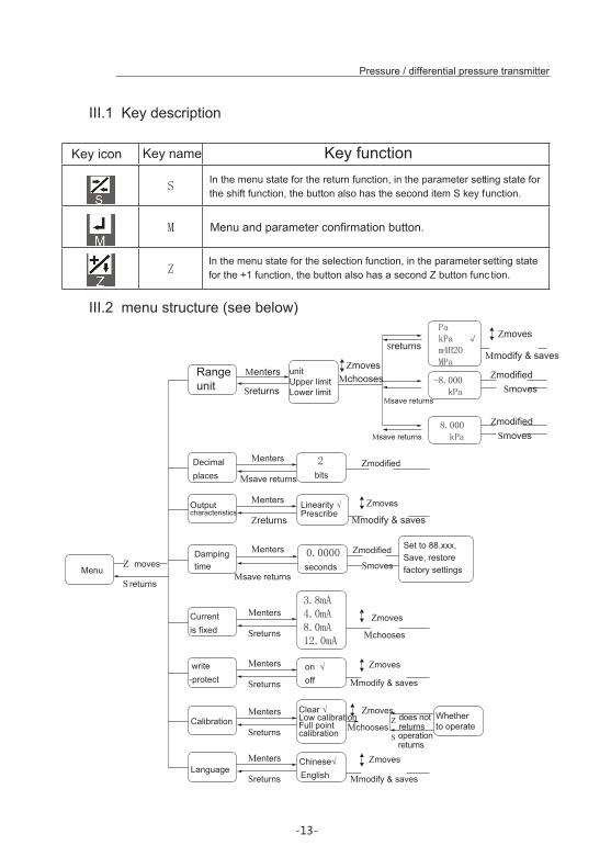
III.1 Key description
III.2 menu structure (see below)
Decimal places
2 bits
Menters
Msave returns
Zmodified
Current is fixed
3.8mA4.0mA8.0mA12.0mA
Menters
Sreturns
Zmoves
Mchooses
Mmodify & saves
Range unit
unitUpper limitLower limit
PakPa √m4H2OMPa
-8.000 kPa
8.000 kPa
Menters
Msave returns
Msave returns
Sreturns
Sreturns
ZmovesMchooses
Zmoves
ZmodifiedSmoves
ZmodifiedSmoves
write-protect
on √off
Menters
Sreturns
Zmoves
Mmodify & saves
LanguageChinese√English
Menters
Sreturns
Zmoves
Mmodify & saves
Zmodified
SmovesDamping time
0.0000 seconds
Menters
Msave returnsMenu
S returns
Z moves
Mmodify & savesOutput characteristics
Linearity √Prescribe
Menters
Zreturns
Zmoves
Whether to operateCalibration
Menters
Sreturns
Zmoves
MchoosesS operation
returns
Z does not returns
Pressure / differential pressure transmitter
Key icon Key name Key functionIn the menu state for the return function, in the parameter setting state for the shift function, the button also has the second item S key function.
Menu and parameter confirmation button.
In the menu state for the selection function, in the parameter setting state for the +1 function, the button also has a second Z button func tion.
Set to 88.xxx,Save, restore factory settings
Clear √Low calibrationFull point calibration

-14-
Pressure / differential pressure transmitter
III.3 Configuration operation
●Example: (For other operations, see the menu structure.)
●Modify the limit
●Modify the lower limit
●Restore factory value
When you want to configure the transmitter, make sure that the transmitter is energized and in the measurement display. Press and hold the M button for about 5 seconds to display the main menu interface and release the button to enter the configuration menu. Press the S key to return Main menu, press the Z key to select the menu item, M key to confirm the key.
When you enter the specific parameter setting interface, press the S key to cycle through the need to modify the bits, including the number, decimal point and minus sign. P ress the Z key to modify the selected bit, the digits are +1, the decimal point moves round, the negative bit is positive and negative. Press M to save the changes and return to the previous menu.
Modified units (KPa, m4H2O, MPa, M, inH20, mmH2O, PSI, bar, mb ar, Pa,%, etc.)On the main menu page,→ press the Z key to move the selection up and down, select "range unit", short press M to enter;→ Press the Z key to move the selection up and down, select "Unit", press M to enter;→ press Z to select the unit, press M key to confirm the selection, then the right side appears √ indicates the operation is successful, otherwisePlease check if "write protection" is "off";
On the main menu page,→ press the Z key to move the selection up and down, select "range unit", short press M to enter;→ press the Z button to move the selection up and down, select "upper limit", short press M to enter;→ press the S key to select the modified bit, press the Z key to modify the number, if the button does not respond, please check the "write protection"Whether it is "off";→ Press M to save and return to the upper interface.
On the main menu page,→ press the Z key to move the selection up and down, select "range unit", short press M to enter;→ press the Z key to move the selection up and down, select "lower limit", short press M to enter;→ press the S key to select the modified bit, press the Z key to modify the number, if the button does not respond, please check the "write protection"Whether it is "off";→ Press M to save and return to the upper interface.
On the main menu page,→ press the Z key to move up and down options, select "damping time", short press M to enter;→ press the S key to select the modified bit, press the Z key to modify the number, the number is set to "88.888";→ Press M to save, then the transmitter's parameters will be restored to the factory state.If there is no key operation for 15 seconds in the menu or parameter setting state, the transmitter will automatically exit the parameterThe array is configured and returned to the measurement
-15-
Pressure / differential pressure transmitter
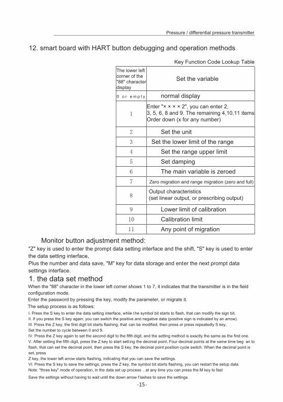
12. smart board with HART button debugging and operation methods
Set the variable
0 o r e m p t y normal display
1
2 Set the unit3 Set the lower limit of the range4 Set the range upper limit5 Set damping6 The main variable is zeroed7 Zero migration and range migration (zero and full)
8
9 Lower limit of calibration10 Calibration limit11 Any point of migration
Monitor button adjustment method:
1. the data set method
The lower left corner of the "88" character display
Enter "× × × × 2", you can enter 2,3, 5, 6, 8 and 9. The remaining 4,10,11 itemsOrder down (x for any number)
Output characteristics (set linear output, or prescribing output)
"Z" key is used to enter the prompt data setting interface and the shift, "S" key is used to enter the data setting interface,Plus the number and data save, "M" key for data storage and enter the next prompt data settings interface.
When the "88" character in the lower left corner shows 1 to 7, it indicates that the transmitter is in the field configuration mode.Enter the password by pressing the key, modify the parameter, or migrate it.The setup process is as follows:I. Press the S key to enter the data setting interface, while the symbol bit starts to flash, that can modify the sign bit.II. If you press the S key again, you can switch the positive and negative data (positive sign is indicated by an arrow).III. Press the Z key, the first digit bit starts flashing, that can be modified, then press or press repeatedly S key,Set the number to cycle between 0 and 9.IV. Press the Z key again to set the second digit to the fifth digit, and the setting method is exactly the same as the first one.V. After setting the fifth digit, press the Z key to start sett ing the decimal point. Four decimal points at the same time beg an to flash, that can set the decimal point, then press the S key, the decimal point position cycle switch. When the decimal point is set, pressZ key, the lower left arrow starts flashing, indicating that you can save the settings.VI. Press the S key to save the settings; press the Z key, the symbol bit starts flashing, you can restart the setup data.Note: "three key" mode of operation, in the data set up process , at any time you can press the M key to fast
Save the settings without having to wait until the down arrow f lashes to save the settings.
Key Function Code Lookup Table
-16-
Pressure / differential pressure transmitter
2. the key function description (according to: key functioncode look-up table corresponding to the function of operation)
2.1 main variable zero (clear) function
2.2 Configuration function
2.2.1 Unit setting
2.2.2 Range setting
2.2.3 damping settings
In the real-time normal display state, while pressing the "M" + "Z" key, and keep 5 seconds, directly into the main variableZero function. After entering the "main variable zero" function , the lower left corner of the function code shows "6", the lower area shows "YES"Or "NO". When "YES" is displayed, press "M" or "Z" to execute the "Main Variable Zero" operation. When this function is executed, the output pressure is "0". When "NO " is displayed, press "M" or "Z" to end the "Main Variable Zero" operation.Press the "S" key to toggle between "YES" and "NO".
In the real-time normal display state, press the Z key to enter the configuration data setting state. Enter a different opcode,Then enter the different function settings interface. If the setting data exceeds the limit, the LCD displays "OVER", then press the S key orThe Z key can be reset. After the completion of the settings to return to normal display state, if in 10 seconds again press the Z key,The configuration setup process is resumed and the input code verification step is ignored. After entering the configuration data set, if 2 pointsIf there is no button in the clock, it will return to normal display. The first four digits of the input code can be any number, and the fifth bit corresponds to the opcodeFunction, enter other data, then return to the normal display.
When the unit is set, the currently selected unit flashes in the lower right corner of the LCD. The unit setup process is as follows:1) Press the "S" key to select the main unit (kPa, Torr, atm, MPa, inHO, inHG, FtHO, mmHO,mmHG, psi, bar, mbar, gcm, kgcm, Pa, etc.);2) Press the "Z" key or the "M" key to confirm the currently selected unit of the main variableand enter the "Lower limit settings "function interface.
When setting the range, you must first enter the "range lower limit" and enter the "range limit".Set the range process, the lower left corner of the opcode display "03" or "04", respectively, corresponding to the input "lower limit"And "upper limit". After the lower limit of the range is entered, the setting of "Range upper limit" is automatically entered.
You can enter the damping page directly by entering the opcode "5", or set the damping directly after setting the range limit. The lower left corner of the opcode shows "05", that set the damping value. The input of the damping valueIf the input damping value is "05678", the "Restore factory setting" operation will be performed automatically. (This is required to be executed at the factory.) Note: If the input damping value is "05678" "Data backup" operation
-17-
Pressure / differential pressure transmitter
2.2.4 Output feature setting
2.2.5 Zero migration and range migration [zero and full]
2.2.6 upper and lower limit calibration and any point of migration
2.2.7 Display the variable settings
When the output characteristics are set, the lower right corner of the LCD flashes to display the currently selected output characteristic (linear LIN output, orPrescribing SQRT output). The setup process is as follows:1) Press the "S" key to select the current output mode in turn; (LIN indicates the linear currentoutput, SQRT represents the square current output)2) Press the "Z" key or the "M" key to confirm the currently selected output characteristic andend the current setting and return to the "End Setting" function screen. 【Function code "0" is displayed at the bottom of the LCD. If there is no key operation within 10 seconds, it will return to normal display, otherwise it will continue to set from the range unit [no need to re-enter
In the real-time normal display state, while pressing the "Z" key and "S" key, and keep 5 seconds into the zero migrationAnd range migration status. At this point the lower left corner of the opcode display "07", that can be zero and full operation."Zero point transition", that is, "zero" operation: the current pressure is set to the lower range, the transmitter output adjustmentFor 4mA. "Range migration", ie "rollover" operation: current pressure is set to range upper limit, transmitter outputAdjust to 20mA. During the setting process, if no button is pressed for 2 minutes, the normal display status is returned.
Lower limit calibration: in real-time normal display state, press the Z key to enter the opcode set state, LCD lower left corner"1" is displayed. Enter "× × × × 9" (that is, the previous 4 can be any number), then enter the lower limit of the calibration state.Given the lower limit of the corresponding pressure signal, after stabilization, through the "one, data set method" set the lower limit calibration value, finishedLower limit calibration.Upper limit calibration: first enter the lower limit calibration function interface, and then press the "Z" or "M" key down, when the lower left cornerWhen the opcode "10" is displayed, it means entering the calibration upper limit function. Given the upper limit of the corresponding pressure signal, after stabilization,Set the upper limit calibration value by using the "data setting method" to complete the upper limit calibrationAny point of migration: first enter the lower limit calibration function interface, and then press the "Z" or "M" key down, when the lower left cornerWhen the opcode is displayed "11", it means to enter the arbitrary point of the migration function. Given the pressure signal, stabilize after passing the "numberAccording to set the method "set the current pressure value (ie , the given pressure value), complete any point migration
Display variables are "current", "percentage", "main variable" three, can display one or alternately display two of them. In the real-time normal display state, the use of S key can change the two display variables,
-18-
Pressure / differential pressure transmitter
2.2.8 Restore factory settings
13. Out of the box and check
14. Notes:
15. The warranty
when the two display variables set to the same parameters, the screen fixed display a variable; when the two display variables set to different parameters, the screen Alternately displays two variables. Method: Press the "S" key, the current display variable (such as: current) changes, cycle display "current, percentage, the main variable", when the required display variables (such as: the main variable) appears on the screen, release "S" key, that is, to achieve the display variable "current" to "main variable".
If the transmitter has been factory, the configuration and other data were backed up, you can enter the damping by pressing the key"5678" to the scene to recover data.By pressing the key, in the fifth entry, enter the damping, enter "05678" and save, will restore the backup data. [This operation does not affect the true damping value]
caveat! Damage to the product can not be repaired when one of the following conditions occurs:I, the measured pressure exceeds the product "overload capacity".II, the power supply is greater than 36VDC or AC power supply.III, with a hard object pestering the diaphragm or the measured medium coagulation.IV, measurement of corrosive or beer, hydrogen and other media, and the order is not stated.
I, since the date of delivery within one year, due to material and process problems caused by quality defects or performance can not reachContracted products are given free repair or replacement.II, pressure diaphragm deformation or other damage caused by improper use of the user, does not belong to the warranty list.
1. Please check the packaging before the box is not deformed or damaged, and photographed asa basis for post-compensation.2. After unpacking, please check whether the contents of the deformation or damage and all thequality problems, and take pictures as a matter of timeCompensation basis.3. Please check whether the content is consistent with the order, the number is correct.4. If you have any of the above abnormal conditions, please contact us within 7 days (togetherwith the photo), otherwise it will not be given freeReplacement or repair.5. Packing accessories: a) brochures
B) product certification

This manual is only used to provide information, we will do our best to ensure the accuracy of the information, No indication or suggest the products or services described in complete accord with the actual Without indication or suggestion shows the product description and service in accord with the actual one. the manual can’t be used as a bond or proof..All of the manuals sold and distributed are bound by our terms and conditions, itis forbiden to use without authorization, we keep the rights that modify or improve the product design and specifications without any notice at any time.