manual fundamental hydraulic systms
DESCRIPTION
Hydraulics Example SolutionsTRANSCRIPT
– Test Manual – for
© 2010 Pearson Education, Inc., Upper Saddle River, NJ. All rights reserved. This publication is protected by Copyright and written permission should be obtained
from the publisher prior to any prohibited reproduction, storage in a retrieval system, or transmission in any form or by any means, electronic, mechanical, photocopying,recording, or likewise. For information regarding permission(s), write to: Rights and Permissions Department, Pearson Education, Inc., Upper Saddle River, NJ 07458.

Contents
1 FUNDAMENTAL PROPERTIES OF WATER 1
2 PRESSURE AND PRESSURE FORCES 6
3 WATER FLOW IN PIPES 18
4 PIPELINES AND PIPE NETWORKS 27
5 WATER PUMPS 42
6 WATER FLOW IN OPEN CHANNELS 54
7 GROUNDWATER HYDRAULICS 66
8 HYDRAULIC STRUCTURES 80
9 WATER PRESSURE, VELOCITY, AND DISCHARGE MEASUREMENTS 88
10 HYDRAULIC SIMILITUDE AND MODEL STUDIES 93
11 HYDROLOGY FOR HYDRAULIC DESIGN 101
12 STATISTICAL METHODS IN HYDROLOGY 122
© 2010 Pearson Education, Inc., Upper Saddle River, NJ. All rights reserved. This publication is protected by Copyright and written permission should be obtainedfrom the publisher prior to any prohibited reproduction, storage in a retrieval system, or transmission in any form or by any means, electronic, mechanical, photocopying,recording, or likewise. For information regarding permission(s), write to: Rights and Permissions Department, Pearson Education, Inc., Upper Saddle River, NJ 07458.

© 2010 Pearson Education, Inc., Upper Saddle River, NJ. All rights reserved. This publication is protected by Copyright and written permission should be obtainedfrom the publisher prior to any prohibited reproduction, storage in a retrieval system, or transmission in any form or by any means, electronic, mechanical, photocopying,recording, or likewise. For information regarding permission(s), write to: Rights and Permissions Department, Pearson Education, Inc., Upper Saddle River, NJ 07458.

TEST QUESTIONS - CHAPTER #1
Short Answer Questions
1. Define specific heat. Ans. The amount of energy required to raise the temperature of a substance by 1oC.
2. Define cavitation. Ans. Cavitation is rapid water vaporization that occurs in closed systems (e.g., pipelines or
pumps) in regions where the pressure drops below the vapor pressure.
3. The amount of energy required to change water from one phase to another is called a) heat of fusion b) heat of vaporization c) specific heat d) latent energy Ans. (d)
4. (T or F) To change water from one phase to another requires a change in heat or pressure.Ans. True
5. Two locations in closed hydraulic systems where cavitation is likely are (pressure tanks, pipelines, nozzles, pumps, hydraulic jacks). Ans. Pipelines and pumps
6. What would be the ramification to our planet if a) water did not have a high heat capacity? b) water did not have a high dissolving capacity? c)water did not have a unique temperature-density relationship? (Give one answer to each question.) Ans. a) Temperature differences between locations on the planet would be much greater. b)
Nutrients would not be easily absorbed by plants and animals. c) Lakes that froze completely from the bottom up would kill most life forms each winter.
7. What is the difference between density and specific weight? Ans. Density is mass per unit volume and specific weight is weight per unit volume.
8. Define specific gravity of a liquid. Ans. Specific gravity is the ratio of the specific weight of any liquid to that of water at 4˚C.
9. (T or F) Water, like most substances, becomes denser as its temperature decreases. Ans. False – water becomes less dense at temperatures lower than 4˚C and expands even
more when it freezes.
10. (T or F) The density of ice is the same as that of liquid water at the same temperature. Ans. False
11. Derive the relationship between specific weight and density using Newton’s 2nd Law (F=ma)Ans. F = m·a Letting a = g results in Equation 1.1:
W = m·g, and dividing both sides of the equation by volume yields = ·g
1
© 2010 Pearson Education, Inc., Upper Saddle River, NJ. All rights reserved. This publication is protected by Copyright and written permission should be obtainedfrom the publisher prior to any prohibited reproduction, storage in a retrieval system, or transmission in any form or by any means, electronic, mechanical, photocopying,recording, or likewise. For information regarding permission(s), write to: Rights and Permissions Department, Pearson Education, Inc., Upper Saddle River, NJ 07458.
12. All of the following are true except: a) The density of water is greatest at 4˚C.b) Specific weight can be found by multiplying density and gravitational acceleration. c) The densities of objects on the moon are the same as they are on earth. d) The specific weights of objects on the moon are the same as they are on earth. Ans. (d) is not true
13. Dividing the specific weight by the mass density of a liquid yields a) the specific gravity of the liquid. b) the weight of the liquid. c) the gravitational acceleration d) none of the above. Ans. (c) is true
14. Define absolute viscosity. Ans. Absolute viscosity is the proportionality constant relating shearing stress to the rate of
angular deformation (d /dt) in Newtonian fluids.
15. (T or F) Newtonian fluids were consumed in great quantities by Sir Isaac Newtonian. Ans. False
16. Kinematic viscosity a) is the proportionality constant relating shearing stress to the rate of angular deformation. b) is expressed in units of stress times the time interval (N·sec/m2).c) is found by dividing the absolute viscosity by the mass density at the same temperature. d) is not related to the density of a fluid.Ans. c
17. Shear stresses in water are related to all of the following except: a) The surface tension of the water. b) The velocity difference between adjacent layers. c) The distance between adjacent layers. d) The temperature of the water. Ans. (a) is not true
18. Define surface tension. Ans. Surface tension is the property of a fluid that causes it to seek a minimum possible
surface area. It occurs because fluid molecules seek to bond with other fluid particles, but at the surface are not able to bond in all directions and therefore form stronger bonds with adjacent liquid molecules.
19. (T or F) Determination of the capillary rise in a small tube is based on a force balance. Ans. True
2
© 2010 Pearson Education, Inc., Upper Saddle River, NJ. All rights reserved. This publication is protected by Copyright and written permission should be obtainedfrom the publisher prior to any prohibited reproduction, storage in a retrieval system, or transmission in any form or by any means, electronic, mechanical, photocopying,recording, or likewise. For information regarding permission(s), write to: Rights and Permissions Department, Pearson Education, Inc., Upper Saddle River, NJ 07458.
20. Give two examples of surface tension at work (i.e., evidence of surface tension). Ans. A steel needle floating on water, the spherical shape of dewdrops, and the rise or fall of
liquid in capillary tubes are the results of surface tension.
21. Capillary rise of water in a small tube is dependent on all of the following except: a) the elasticity of water. b) the nature of the solid surface. c) the temperature of the water. d) the diameter of the tube. e) the angle of contact between the water and the tube. Ans. a
22. Define bulk modulus of elasticity. Ans. The bulk modulus of elasticity is the inverse of the compressibility of a fluid. Expressed
mathematically, it is the ratio of the pressure change that is exerted on a liquid to the ratio of the change in volume over the original volume.
23. (T or F) Water is less compressible than steel, hence it is commonly assumed to be incompressible. Ans. False
24. The bulk modulus of elasticity is not dependent upon: a) initial pressure b) initial volume c) pressure change d) volume change Ans. a
3
© 2010 Pearson Education, Inc., Upper Saddle River, NJ. All rights reserved. This publication is protected by Copyright and written permission should be obtainedfrom the publisher prior to any prohibited reproduction, storage in a retrieval system, or transmission in any form or by any means, electronic, mechanical, photocopying,recording, or likewise. For information regarding permission(s), write to: Rights and Permissions Department, Pearson Education, Inc., Upper Saddle River, NJ 07458.
Problems
1. In a thermal container, 10 grams of ice at -6oC is mixed with 14 grams of water at 20oC.Determine whether or not all the ice will be melted. If the ice is melted, determine the final temperature once equilibrium is established.
Ans. E1 = energy required to melt ice = (10 g)(0 C - (-6 C))(0.465 cal/g· C) = 27.9 cal
To melt the ice, the temperature of the water will decrease to:
27.9 cal = (14 g)(20 C - T1)(1 cal/g· C); T1 = 18.0 C
The energy lost by the water (to lower its temp. to 18.0 C) is required to melt the ice.
Therefore, the final temperature of the water is:
[(14 g)(18.0 C - T2)(1 cal/g· C)] = [(10 g)(T2 - 0 C)( 1 cal/g· C)] ; T2 = 10.5 C
2. A container has a 5-m3 volume capacity and weights 1500 N when empty and 47,000 N when filled with a liquid. What is the mass density and specific gravity of the liquid?
Ans. The mass of liquid can be found using = /g and = weight/volume, thus
= weight/volume= (47000 N – 1500 N)/(5 m3) = 9.10 x 10³ N/m3
= /g = (9.1 x 10³ N/m3)/(9.81 m/s2); = 928 kg/m3
Specific gravity (S.G.) = / (H2O at 4C) = (9.10 x 10³ N/m3)/9.81 x 103 N/m3)
S.G. = 0.928
3. The specific weight of a liquid is 55.5 lbs/ft3. Determine the weight, density, and specific gravity of the liquid if it occupies a volume of 20 ft3. Provide results in both the British system and S.I. Units.
Ans. = 55.5 lb/ft3 = W/Vol; thus, W = ·Vol = (55.5 lb/ft3)(20 ft3) = 1,110 lb (or 4,930 N)
= /g = (55.5 lb/ft3)/(32.2 ft/s2) = 1.72 slug/ft3 (or 887 kg/m3)
S.G. = liquid/ water at 4 C = (55.5 lb/ft3)/(62.4 lb/ft3) = 0.889
4. Velocity measurements are made along a cross section of a flow field. The velocity at two points (2 cm apart) are 4.8 m/sec and 2.4 m/sec respectively. What is the magnitude of the shear stress at this location if the velocity profile is linear and the fluid is water at 20 C?
Ans. The shearing stress can be found using Newton’s law of viscosity.
= (dv/dy) = (1.00 x 10⁻³ N sec/m2)[{(4.8 – 2.4)m/sec}/(0.02 m)] = 0.12 N/m2
4
© 2010 Pearson Education, Inc., Upper Saddle River, NJ. All rights reserved. This publication is protected by Copyright and written permission should be obtainedfrom the publisher prior to any prohibited reproduction, storage in a retrieval system, or transmission in any form or by any means, electronic, mechanical, photocopying,recording, or likewise. For information regarding permission(s), write to: Rights and Permissions Department, Pearson Education, Inc., Upper Saddle River, NJ 07458.

5
5. The 25-cm diameter ram of a hydraulic lift slides in a 25.015-cm diameter cylinder. The viscosity of the oil filling the gap is 0.04 N . sec/m2. If the speed of the ram is 15 cm/sec, determine the frictional resistance force when 3 m of the ram is engaged in the cylinder. Assume concentric motion and the velocity distribution in the gap is linear.
Ans. The shearing stress can be found using Newton’s law of viscosity.
= (dv/dy) = (0.04 N sec/m2)[(15 cm/s)/ ((25.015 cm – 25 cm)/(2))] = 80 N/m2
Fshear resistance = A = (80 N/m2)[( )(0.25 m)(3 m)]
Fshear resistance = 188 N
6. Mercury (S.G. = 13.6) is used in a glass tube to measure pressure. If the surface tension is 0.57 N/m and the contact angle ranges from 40˚ to 50˚, determine the minimum diameter of the tube so that the measurement error is less than 0.5 mm.
Ans. The appropriate form of the capillary rise equation is
D = [(4)( )(sin )] / [( )(h)]
= [(4)(0.57 N/m)(sin 50 )] / [13.6)(9790 N/m3)(0.5x10-3 m)]
D = 0.0262 m = 2.62 cm
7. A steel tank holds 120 ft3 of water with a weight of 7,488 lbs at atmospheric pressure (14.7 lbs/in.2). Determine its density and the new density if the pressure is raised to 1470 lbs/in.2.
Ans. m = W/g = (7488 lb)/(32.2 ft/s2) = 232.5 slug
= m/Vol = (232.5 slug)/(120 ft3) = 1.94 slug/ft3
Vol = (- P/Eb)(Vol) = [-(1470 psi –14.7 psi)/(320000 psi)]*(120 ft3) = -0.546 ft3
new = (232.5 slug)/(120 ft3 – 0.546 ft3)
new = 1.95 slug/ft3
© 2010 Pearson Education, Inc., Upper Saddle River, NJ. All rights reserved. This publication is protected by Copyright and written permission should be obtainedfrom the publisher prior to any prohibited reproduction, storage in a retrieval system, or transmission in any form or by any means, electronic, mechanical, photocopying,recording, or likewise. For information regarding permission(s), write to: Rights and Permissions Department, Pearson Education, Inc., Upper Saddle River, NJ 07458.

TEST QUESTIONS - CHAPTER #2
Short Answer Questions
1. State Pascal’s law. Ans. A pressure applied at any point in a liquid at rest is transmitted equally and
undiminished in all directions to every other point in the liquid.
2. (T or F) The difference in pressure between any two points in still water is always equal to the product of the density of water and the difference in elevation between the two points.Ans. False – specific weight, not density.
3. Gage pressure is defined asa) the pressure measured above atmospheric pressure. b) the pressure measured plus atmospheric pressure. c) the difference in pressure between two points. d) pressure expressed in terms of the height of a water column. Ans. (a) is true
4. Some species of seals dive to depths of 400 m. Determine the pressure at that depth in N/m2
assuming sea water has a specific gravity of 1.03.Ans. P = ·h = (1.03)(9790 N/m3)(400 m) = 4.03·106 N/m2
5. Pressure below the surface in still water (or hydrostatic pressure) a) is linearly related to depth.b) acts normal (perpendicular) to any solid surface. c) is related to the temperature of the fluid. d) at a given depth, will act equally in any direction. e) all of the above. f) (a) and (b) only. Ans. (e)
6. (T or F) A single-reading manometer makes use of a reservoir of manometry fluid with a large cross sectional area so that pressure calculations are only based on one reading.Ans. True.
7. What is an open manometer? Ans. A manometer is a pressure measurement device that utilizes fluids of known specific gravity and differences in fluid elevations. An open manometer has one end open to the air.
8. (T or F) The total hydrostatic pressure force on any submerged plane surface is equal to the product of the surface area and the pressure acting at the center of pressure of the surface. Ans. False. The total hydrostatic pressure force on any submerged plane surface is equal to the product of the surface area and the pressure acting at the centroid of the plane surface.
6
© 2010 Pearson Education, Inc., Upper Saddle River, NJ. All rights reserved. This publication is protected by Copyright and written permission should be obtainedfrom the publisher prior to any prohibited reproduction, storage in a retrieval system, or transmission in any form or by any means, electronic, mechanical, photocopying,recording, or likewise. For information regarding permission(s), write to: Rights and Permissions Department, Pearson Education, Inc., Upper Saddle River, NJ 07458.

9. A surface of equal pressure requires all of the following except:a) points of equal pressure must be at the same elevation. b) points of equal pressure must be in the same fluid. c) points of equal pressure must be interconnected. d) points of equal pressure must be at the interface of immiscible fluids. Ans. (d); points of equal pressure do not need to be at and interface of fluids.
10. The center of pressure on inclined plane surfaces is: a) at the centroid. b) is always above the centroid. c) is always below the centroid. d) is not related to the centroid.Ans. (c); points of equal pressure do not need to be at and interface of fluids.
11. (T or F) The location of the centroid of a submerged plane area and the location where the resultant pressure force acts on that area are identical. Ans. False. The resultant force acts at the center of pressure.
12. The equation for the determination of a hydrostatic force on a plane surface and its location are derived using al of the following concepts except
a) integration of the pressure equation b) moment of inertia concept c) principle of moments d) Newton’s 2nd Law Ans. Since this deals with hydrostatics (i.e., no acceleration), (d) is the answer.
13. The equation for the righting moment on a submerged body is M = W GM sin , where GM = MB – GB or MB + GB. Under what conditions is the sum used instead of the difference? Ans. Use the sum when the center of gravity is below the center of buoyancy.
14. Given the submerged cube with area (A) on each face, derive the buoyant force on the cube if the depth (below the surface of the water) to the top of the cube is x and the depth to the bottom of the cube is y. Show all steps.
Ans. Fbottom= Pavg·A = ·y·A; Ftop= Pavg·A = ·x·A; Fbottom-Ftop= ·(y-x)·A= ·Vol
15. A 3 ft x 3 ft x 3 ft wooden cube (specific weight of 37 lb/ft3) floats in a tank of water. How much of the cube extends above the water surface? If the tank were pressurized to 2 atm (29.4 psi), how much of the cube would extend above the water surface? Explain.Ans. Fy=0; W = B; (37 lb/ft3)(3 ft)3 = (62.3 lb/ft3)(3 ft)2(y); y = 1.78 ft Note: The draft
does not change with pressure. That is, the added pressure on the top of the cube would be compensated by the increased pressure in the water under the cube.
7
© 2010 Pearson Education, Inc., Upper Saddle River, NJ. All rights reserved. This publication is protected by Copyright and written permission should be obtainedfrom the publisher prior to any prohibited reproduction, storage in a retrieval system, or transmission in any form or by any means, electronic, mechanical, photocopying,recording, or likewise. For information regarding permission(s), write to: Rights and Permissions Department, Pearson Education, Inc., Upper Saddle River, NJ 07458.

16. The derivation of the flotation stability equation utilizes which principles? Note: More than one answer is possible.
a) moment of a force couple b) moment of inertia c) Newton’s 2nd Law d) buoyancy Ans. It utilizes (a), (b), and (d).
17. Rotational stability is a major concern in naval engineering. Draw the cross section of the hull of a ship and label the three important points (i.e., centers) which affect rotational stability.Ans. See Figure 2.16.
18. A 4 m (length) by 3 m (width) by 2 m (height) homogeneous box floats with a draft 1.4 m. What is the distance between the center of buoyancy and the center of gravity? Ans. G is 1 m up from bottom and B is 0.7 m up from bottom. Thus, GB = 0.3 m.
19. Determine the waterline moment of inertia about the width of a barge (i.e., used to assess stability from side to side about its width) if it is 30 m long, 12 m wide, and 8 m high? Ans. Io =(30m)(12m)3/12 = 4320 m4
20. (T or F) Floatation stability is dependent on the relative positions of the center of gravity and the center of buoyancy. Ans. True.
8
© 2010 Pearson Education, Inc., Upper Saddle River, NJ. All rights reserved. This publication is protected by Copyright and written permission should be obtainedfrom the publisher prior to any prohibited reproduction, storage in a retrieval system, or transmission in any form or by any means, electronic, mechanical, photocopying,recording, or likewise. For information regarding permission(s), write to: Rights and Permissions Department, Pearson Education, Inc., Upper Saddle River, NJ 07458.
Problems
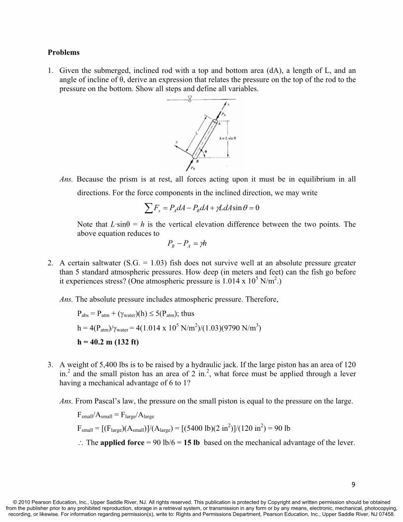
1. Given the submerged, inclined rod with a top and bottom area (dA), a length of L, and an angle of incline of , derive an expression that relates the pressure on the top of the rod to the pressure on the bottom. Show all steps and define all variables.
Ans. Because the prism is at rest, all forces acting upon it must be in equilibrium in all
directions. For the force components in the inclined direction, we may write
0sinLdAdAPdAPF BAx
Note that L·sin = h is the vertical elevation difference between the two points. The above equation reduces to
hPP AB
2. A certain saltwater (S.G. = 1.03) fish does not survive well at an absolute pressure greater than 5 standard atmospheric pressures. How deep (in meters and feet) can the fish go before it experiences stress? (One atmospheric pressure is 1.014 x 10⁵ N/m2.)
Ans. The absolute pressure includes atmospheric pressure. Therefore,
Pabs = Patm + ( water)(h) 5(Patm); thus
h = 4(Patm)/ water = 4(1.014 x 10⁵ N/m2)/(1.03)(9790 N/m3)
h = 40.2 m (132 ft)
3. A weight of 5,400 lbs is to be raised by a hydraulic jack. If the large piston has an area of 120 in.2 and the small piston has an area of 2 in.2, what force must be applied through a lever having a mechanical advantage of 6 to 1?
Ans. From Pascal’s law, the pressure on the small piston is equal to the pressure on the large.
Fsmall/Asmall = Flarge/Alarge
Fsmall = [(Flarge)(Asmall)]/(Alarge) = [(5400 lb)(2 in2)]/(120 in2) = 90 lb
The applied force = 90 lb/6 = 15 lb based on the mechanical advantage of the lever.
9
© 2010 Pearson Education, Inc., Upper Saddle River, NJ. All rights reserved. This publication is protected by Copyright and written permission should be obtainedfrom the publisher prior to any prohibited reproduction, storage in a retrieval system, or transmission in any form or by any means, electronic, mechanical, photocopying,recording, or likewise. For information regarding permission(s), write to: Rights and Permissions Department, Pearson Education, Inc., Upper Saddle River, NJ 07458.

4. The two containers of water shown below have the same bottom areas (2 m by 2 m), the same depth of water (10 m), and are both open to the atmosphere. However, the L-shaped container on the right holds less fluid. Determine hydrostatic force (in kN), not the pressure, on the bottom of each container.
Ans. The pressure on the bottom of each container is identical, based on
P = ( water)(h) = (9790 N/m3)(10 m) = 97.9 kN/m2
The force on the bottom of each is identical as well, based on
F = P·A = (97.9 kN/m2)(2 m)(2 m) = 391 kN
5. The gage pressure at the bottom of a water tank reads 30 mm of mercury (S.G. = 13.6). The tank is open to the atmosphere. Determine the water depth (in cm) above the gage. Find the equivalency in N/m2 of absolute pressure at 20°C.
Ans. Since mercury has a specific gravity of 13.6, the water height can be found from
hwater = (hHg)(SGHg) = (30 mm)(13.6) = 408 mm = 40.8 cm of water
Pabs = Pgage + Patm = [(40.8 cm){(1 m)/(100 cm)} + 10.3 m] = 10.7 m of water
Pabs = (10.7 m)(9790 N/m3) = 1.05 x 10⁵ N/m2
6. A triangle is submerged beneath the surface of a fluid. Three pressures (Px , Py , and Ps) act on the three tiny surfaces of length ( y, x, and s). Prove that Px = Ps and Py = Ps (i.e., pressure is omni-directional) using principles of statics. (Note that Px acts on y, Py acts on
x, and Ps acts on s. Also, the angle between the horizontal leg of the triangle and the hypotenuse is .)
Ans. Fx = 0; (Px )( y) – (Ps sin )( s) = 0; since ( s·sin ) = y, Ps = Px
Px
Ps
Py
Fy = 0; (Py )( x) – (Ps cos )( s) – ( x· y/2)( ) = 0;
since ( s·cos ) = x and ( y)( x) 0; Ps = Py
10
© 2010 Pearson Education, Inc., Upper Saddle River, NJ. All rights reserved. This publication is protected by Copyright and written permission should be obtainedfrom the publisher prior to any prohibited reproduction, storage in a retrieval system, or transmission in any form or by any means, electronic, mechanical, photocopying,recording, or likewise. For information regarding permission(s), write to: Rights and Permissions Department, Pearson Education, Inc., Upper Saddle River, NJ 07458.
7. A significant amount of mercury is poured into a U-tube with both ends open to the atmosphere. Then water is poured into one leg of the U-tube until the water column is 1 meter above the mercury-water meniscus. Finally, oil (S.G. = 0.79) is poured into the other leg to a height of 60 cm. What is the elevation difference between the mercury surfaces?
Ans. The mercury-water meniscus will be lower than the mercury-oil meniscus based on the
relative amounts of each poured in and their specific gravity. Also, a surface of equal
pressure can be drawn at the mercury-water meniscus. Therefore,
(1 m)( water) = (h)( Hg) + (0.6 m)( oil)
(1 m)( water) = (h)(SGHg)( water) + (0.6 m)(SGoil)( water); therefore
h = [1 m – (0.6 m)(SGoil)]/(SGHg) = [1 m – (0.6 m)(0.79)]/(13.6)
h = 0.0387 m = 3.87 cm
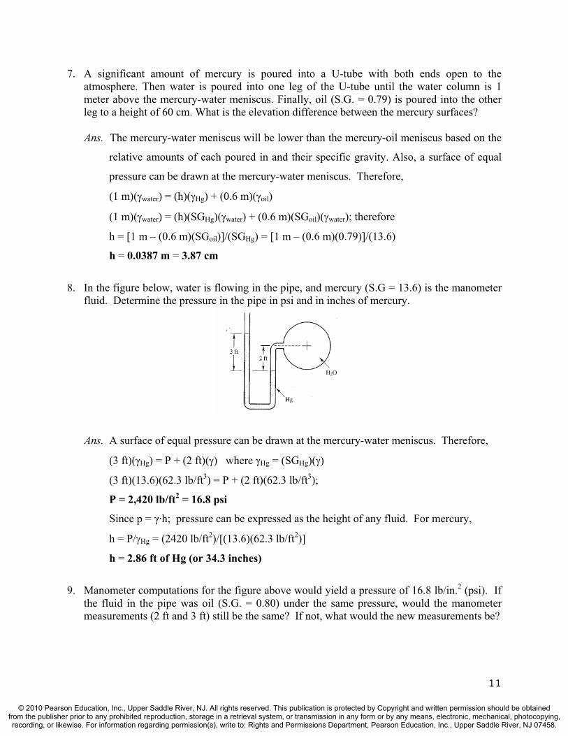
8. In the figure below, water is flowing in the pipe, and mercury (S.G = 13.6) is the manometer fluid. Determine the pressure in the pipe in psi and in inches of mercury.
Ans. A surface of equal pressure can be drawn at the mercury-water meniscus. Therefore,
(3 ft)( Hg) = P + (2 ft)( ) where Hg = (SGHg)( )
(3 ft)(13.6)(62.3 lb/ft3) = P + (2 ft)(62.3 lb/ft3);
P = 2,420 lb/ft2 = 16.8 psi
Since p = ·h; pressure can be expressed as the height of any fluid. For mercury,
h = P/ Hg = (2420 lb/ft2)/[(13.6)(62.3 lb/ft2)]
h = 2.86 ft of Hg (or 34.3 inches)
9. Manometer computations for the figure above would yield a pressure of 16.8 lb/in.2 (psi). If the fluid in the pipe was oil (S.G. = 0.80) under the same pressure, would the manometer measurements (2 ft and 3 ft) still be the same? If not, what would the new measurements be?
11
© 2010 Pearson Education, Inc., Upper Saddle River, NJ. All rights reserved. This publication is protected by Copyright and written permission should be obtainedfrom the publisher prior to any prohibited reproduction, storage in a retrieval system, or transmission in any form or by any means, electronic, mechanical, photocopying,recording, or likewise. For information regarding permission(s), write to: Rights and Permissions Department, Pearson Education, Inc., Upper Saddle River, NJ 07458.
Ans. The measurements will not be the same since oil is now in the manometer instead of
water. A surface of equal pressure can be drawn at the mercury-oil interface.
Ppipe + (2 ft + h)( oil) = (3 ft + 2 h)( Hg)
This is based on volume conservation. If the mercury-oil meniscus goes down h on
the right, it must climb up h on the left making the total difference 2 h. Now
(2.42 x 10³ lb/ft2) + (2 ft + h)(0.80)(62.3 lb/ft3) = (3 ft + 2 h)(13.6)(62.3 lb/ft3)
h = -0.0135 ft
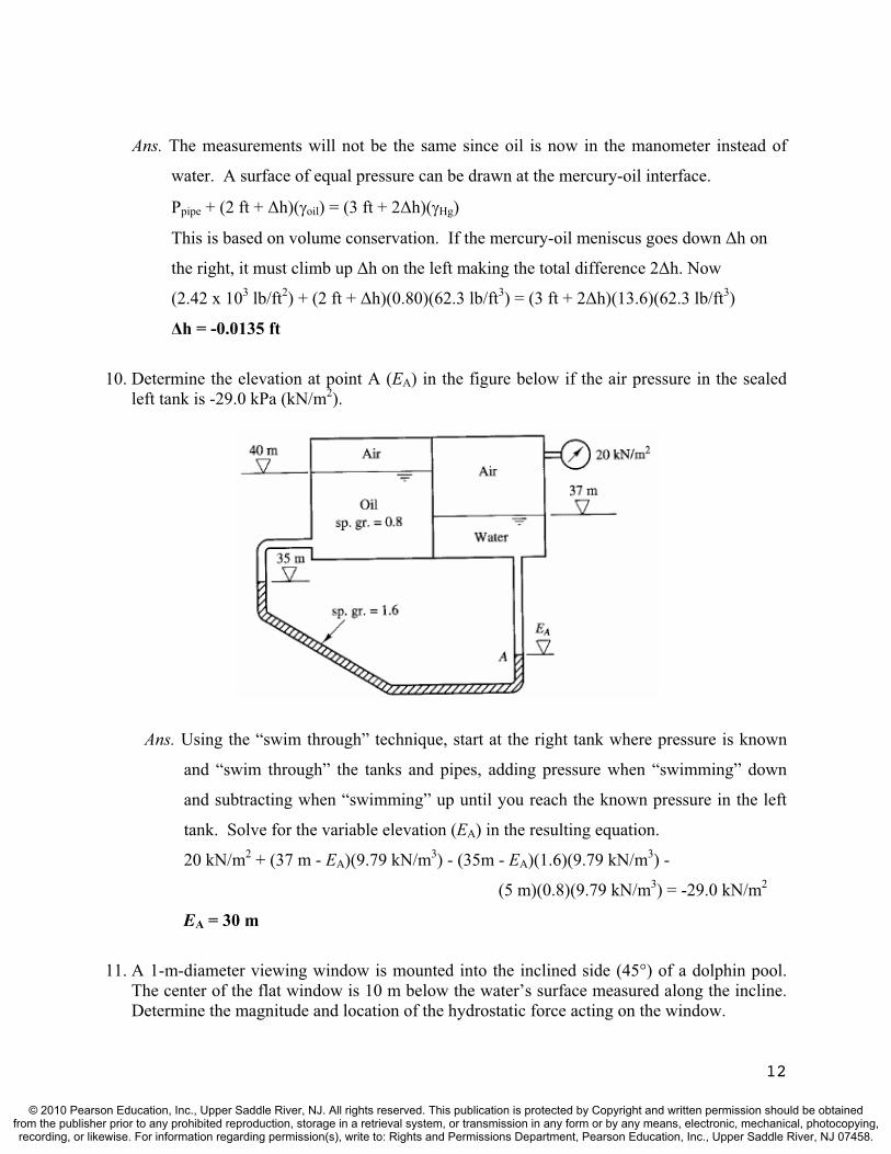
10. Determine the elevation at point A (EA) in the figure below if the air pressure in the sealed left tank is -29.0 kPa (kN/m2).
Ans. Using the “swim through” technique, start at the right tank where pressure is known
and “swim through” the tanks and pipes, adding pressure when “swimming” down
and subtracting when “swimming” up until you reach the known pressure in the left
tank. Solve for the variable elevation (EA) in the resulting equation.
20 kN/m2 + (37 m - EA)(9.79 kN/m3) - (35m - EA)(1.6)(9.79 kN/m3) -
(5 m)(0.8)(9.79 kN/m3) = -29.0 kN/m2
EA = 30 m
11. A 1-m-diameter viewing window is mounted into the inclined side (45°) of a dolphin pool. The center of the flat window is 10 m below the water’s surface measured along the incline. Determine the magnitude and location of the hydrostatic force acting on the window.
12
© 2010 Pearson Education, Inc., Upper Saddle River, NJ. All rights reserved. This publication is protected by Copyright and written permission should be obtainedfrom the publisher prior to any prohibited reproduction, storage in a retrieval system, or transmission in any form or by any means, electronic, mechanical, photocopying,recording, or likewise. For information regarding permission(s), write to: Rights and Permissions Department, Pearson Education, Inc., Upper Saddle River, NJ 07458.

Ans. The hydrostatic force and its locations are:
AhF = (9790 N/m3)(10 m)(sin 45˚)( )(0.5 m)2 = 5.44 x 10⁴ N = 54.4 kN
mmm
myyA
IyP 10)10(4/)1(
64/)1(2
40 10.01 m
12. A square gate 3m x 3m lies in a vertical plane. Determine the total pressure force on the gate and the distance between the center of pressure and the centroid when the upper edge of the gate is at the water surface. Compare these values to those that would occur if the upper edge is 15 m below the water surface.
Ans. The hydrostatic force and its locations are:
AhF = (9790 N/m3)(1.5 m)(9 m2) = 1.32 x 10⁵ N = 132 kN
)5.1(912/)3)(3(
2
30
mmmm
yAIyyP 0.500 m
If the square gate was submerged by 15 m (to the top of the gate):
AhF = (9790 N/m3)(16.5 m)(9 m2) = 1.45 x 10⁶ N = 1,450 kN
)5.16(912/)3)(3(
2
30
mmmm
yAIyyP 0.0455 m; Note that the force increases tremendously with
depth; the distance between the centroid and the center of pressure becomes negligible.
13. A circular gate is installed on a vertical wall as shown in the figure below. Determine the horizontal force, F, necessary to hold the gate closed (in terms of diameter, D, and height, h). Neglect friction at the pivot.
Ans. The hydrostatic force and its locations are:
AhP = ( )(h)[ (D)2/4]
hhD
DyyA
IyP )(4/)(64/)(
2
40 ; yp = D2/(16h) + h (depth to the center of pressure)
Thus, summing moments: Mhinge = 0 ; F(D/2) – P(yp – h) = 0
F(D/2) – {( )(h)[ (D)2/4][D2/(16h)]} = 0; F = (1/32)( )( )(D)3
13
© 2010 Pearson Education, Inc., Upper Saddle River, NJ. All rights reserved. This publication is protected by Copyright and written permission should be obtainedfrom the publisher prior to any prohibited reproduction, storage in a retrieval system, or transmission in any form or by any means, electronic, mechanical, photocopying,recording, or likewise. For information regarding permission(s), write to: Rights and Permissions Department, Pearson Education, Inc., Upper Saddle River, NJ 07458.
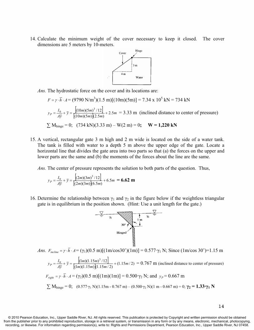
14. Calculate the minimum weight of the cover necessary to keep it closed. The cover dimensions are 5 meters by 10-meters.
Ans. The hydrostatic force on the cover and its locations are:
AhF = (9790 N/m3)(1.5 m)[(10m)(5m)] = 7.34 x 10⁵ kN = 734 kN
mmmm
mmyyA
IyP 5.2)5.2()5)(10(
12/)5)(10( 30 = 3.33 m (inclined distance to center of pressure)
Mhinge = 0; (734 kN)(3.33 m) – W(2 m) = 0; W = 1,220 kN
15. A vertical, rectangular gate 3 m high and 2 m wide is located on the side of a water tank. The tank is filled with water to a depth 5 m above the upper edge of the gate. Locate a horizontal line that divides the gate area into two parts so that (a) the forces on the upper and lower parts are the same and (b) the moments of the forces about the line are the same.
Ans. The center of pressure represents the solution to both parts of the question. Thus,
mmmm
mmyyA
IyP 5.6)5.6()3)(2(
12/)3)(2( 30 = 6.62 m
16. Determine the relationship between 1 and 2 in the figure below if the weightless triangular gate is in equilibrium in the position shown. (Hint: Use a unit length for the gate.)
Ans. AhFincline = ( 1)(0.5 m)[(1m/cos30˚)(1m)] = 0.577· 1 N; Since (1m/cos 30˚)=1.15 m
)2/15.1()2/15.1()15.1)(1(
12/)15.1)(1( 30 m
mmmmmy
yAIyP = 0.767 m (inclined distance to center of pressure)
AhFright = ( 2)(0.5 m)[(1m)(1m)] = 0.500· 2 N; and = 0.667 m Py
Mhinge = 0; (0.577· 1 N)(1.15m - 0.767 m) – (0.500· 2 N)(1 m - 0.667 m) = 0; 2 = 1.33· 1 N
14
© 2010 Pearson Education, Inc., Upper Saddle River, NJ. All rights reserved. This publication is protected by Copyright and written permission should be obtainedfrom the publisher prior to any prohibited reproduction, storage in a retrieval system, or transmission in any form or by any means, electronic, mechanical, photocopying,recording, or likewise. For information regarding permission(s), write to: Rights and Permissions Department, Pearson Education, Inc., Upper Saddle River, NJ 07458.
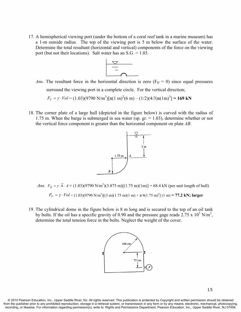
17. A hemispherical viewing port (under the bottom of a coral reef tank in a marine museum) has a 1-m outside radius. The top of the viewing port is 5 m below the surface of the water. Determine the total resultant (horizontal and vertical) components of the force on the viewing port (but not their locations). Salt water has an S.G. = 1.03.
Ans. The resultant force in the horizontal direction is zero (FH = 0) since equal pressures
surround the viewing port in a complete circle. For the vertical direction;
VolFV = (1.03)(9790 N/m3)[ (1 m)2(6 m) – (1/2)(4/3) (1m)3] = 169 kN
18. The corner plate of a large hull (depicted in the figure below) is curved with the radius of 1.75 m. When the barge is submerged in sea water (sp. gr. = 1.03), determine whether or not the vertical force component is greater than the horizontal component on plate AB.
Ans. AhFH = (1.03)(9790 N/m3)(3.875 m)[(1.75 m)(1m)] = 68.4 kN (per unit length of hull)
VolFV = (1.03)(9790 N/m3)[(3 m)(1.75 m)(1 m) + /4(1.75 m)2] (1 m) = 77.2 kN; larger
19. The cylindrical dome in the figure below is 8 m long and is secured to the top of an oil tank by bolts. If the oil has a specific gravity of 0.90 and the pressure gage reads 2.75 x 10⁵ N/m2,determine the total tension force in the bolts. Neglect the weight of the cover.
15
© 2010 Pearson Education, Inc., Upper Saddle River, NJ. All rights reserved. This publication is protected by Copyright and written permission should be obtainedfrom the publisher prior to any prohibited reproduction, storage in a retrieval system, or transmission in any form or by any means, electronic, mechanical, photocopying,recording, or likewise. For information regarding permission(s), write to: Rights and Permissions Department, Pearson Education, Inc., Upper Saddle River, NJ 07458.

Ans. h = P/ = [2.75 x 10⁵ N/m2]/[(0.9)(9790 N/m3)] = 31.2 m of oil
The total upward force is the weight of an oil column 31.2 m high minus the column of
oil that is resident above the gage already.
VolFV = (0.9)(9790 N/m3)[(31.2 m – 0.75 m)-(1/2) (1.0 m)2] (2.0 m)(8.0 m)
VF 4.07 x 10⁶ N; which is the also the total tension force in the bolts holding the top on.
20. The tainter gate section shown in the figure below has a cylindrical surface with a 40-ft radius and is supported by a structural frame hinged at O. The gate is 33 ft long (in the direction perpendicular to the page). Determine the magnitude and location of the total hydrostatic force on the gate.
Ans. The height of the vertical projection is (R)(sin 45˚) = 28.3 ft. Thus,
AhFH = (62.3 lb/ft3)(28.3ft/2)[(33 ft)(28.3 ft)] = 8.23 x 10⁵ lb
Obtain the vertical component of the total pressure force by determining the weight of
the water column above the curved gate. The volume of water above the gate is:
Vol = (Arectangle - Atriangle - Aarc)(length)
Vol = [(40ft)(28.3ft)-(1/2)(28.3ft)(28.3ft)-( /8)(40ft)2](33 ft) = 3,410 ft3
VolFV = (62.3 lb/ft3)(3410 ft3) = 2.12 x 10⁵ lb; The total force is
F = [(8.23 x 10⁵ lb)2 + (2.12 x 10⁵ lb)2]1/2 = 8.50 x 10⁵ lb; = tan-1 (FV/FH) = 14.4˚
Since all hydrostatic pressures pass through point O (i.e., they are all normal to the
surface upon which they act), then the resultant must also pass through point O.
21. A 1-m length of a certain standard steel pipe weighs 248 N and has an outside diameter of 158 mm. Will the pipe sink in glycerin (S.G. = 1.26) if its ends are sealed?
Ans. B = ·Vol = (1.26)(9790 N/m3)[ (0.079 m)2(1 m)] = 242 N < 248 N, thus it will sink.
22. A concrete block that has a total volume of 12 ft3 and a specific gravity of 2.67 is tied to one end of a long cylindrical buoy as depicted in the figure below. The buoy is 10 ft long and is 2 ft in diameter. Unfortunately, it is floating away with 1 ft sticking above the water surface. Determine the specific gravity of the buoy. The fluid is brackish bay water (S.G. = 1.02).
16
© 2010 Pearson Education, Inc., Upper Saddle River, NJ. All rights reserved. This publication is protected by Copyright and written permission should be obtainedfrom the publisher prior to any prohibited reproduction, storage in a retrieval system, or transmission in any form or by any means, electronic, mechanical, photocopying,recording, or likewise. For information regarding permission(s), write to: Rights and Permissions Department, Pearson Education, Inc., Upper Saddle River, NJ 07458.

Ans. W = 2.67 (12 ft3) + (SG) · (1 ft)2(10 ft); B = 1.02 (12 ft3) + 1.02 · (1 ft)2(9 ft)
Fy = 0; or W = B; 32.0 + 31.4(SG) = 12.2 + 28.8; SG = 0.287
23. A 40-ft long, 30-ft diameter cylindrical caisson floats upright in the ocean (S.G. = 1.03) with 10 feet of the caisson above the water. The center of gravity measure 6 ft from the bottom of the caisson. Determine the metacentric height and the righting moment when the caisson is tipped through an angle of 10°.
Ans. The center of buoyancy (B) is 15 feet from the bottom since 30 feet is in the water.
GB = 9.0 ft, and GBIGBMBGMVol
0 ; where Io is the waterline moment of inertial
about the tilting axis. The waterline area is a circle with a 30 ft diameter. Thus,
ftftft
ftGBIGM 0.930304/64/30
Vol 2
40 = 10.9 ft; Note: Vol is the submerged
volume and a positive sign is used since G is located below the center of buoyancy.
sinGMWM = [(1.03)(62.3 lb/ft3)( /4)(30 ft)2(30 ft)](10.9 ft)(sin 10˚)
M = 2.57 x 106 ft-lb (for a heel angle of 10˚)
17
© 2010 Pearson Education, Inc., Upper Saddle River, NJ. All rights reserved. This publication is protected by Copyright and written permission should be obtainedfrom the publisher prior to any prohibited reproduction, storage in a retrieval system, or transmission in any form or by any means, electronic, mechanical, photocopying,recording, or likewise. For information regarding permission(s), write to: Rights and Permissions Department, Pearson Education, Inc., Upper Saddle River, NJ 07458.
TEST QUESTIONS & PROBLEMS - CHAPTER #3
Short Answer Questions
1. In Osborne Reynolds carefully performed experiments, what observation was apparent when laminar flow was occurring in the glass pipe? Ans. When colored water was injected into the flow stream, it appeared as a straight line
extending to the downstream end, indicating laminar flow in the pipe.
2. (T or F) Turbulent flow in a pipe has a more uniform velocity distribution than laminar flow. Ans. True
3. What are the dimensions of Reynolds number when calculations are performed in SI units? Ans. Reynolds number is dimensionless.
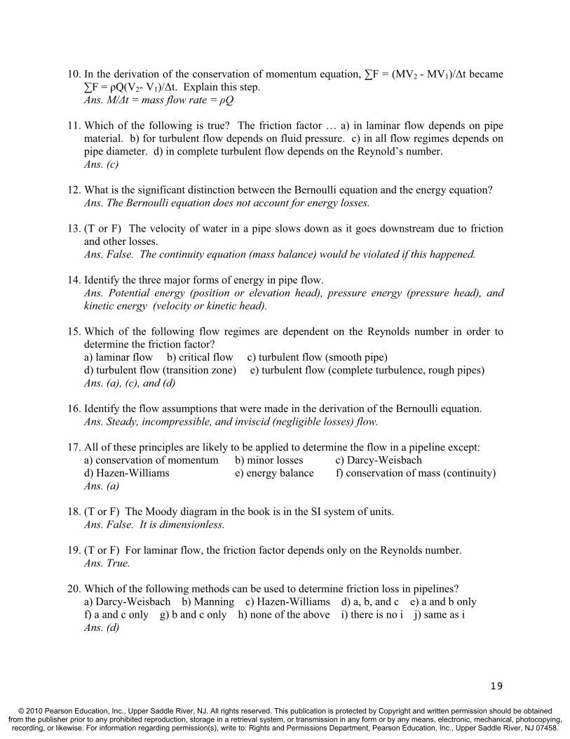
4. Sketch the velocity distribution in a pipe for both laminar and turbulent flow. Ans.
5. (T or F) The transition from laminar to turbulent flow in circular pipes occurs at a Reynolds number of about 1000, but varies somewhat based on differences in experimental conditions Ans. False, it occurs at about 2000.
6. Water loses energy as it flows through a pipe. What causes most of the energy loss? Ans. (a) friction against pipe walls, and b) viscous dissipation due to internal actions of flow
7. The continuity (conservation of mass) equation has the following limitations: a) steady flow b) incompressible flow c) inviscid (negligible viscosity) flowd) atmospheric pressure e) laminar flow f) turbulent flowAns. (a) and (b)only
8. Water sprays through a 6-inch-diameter nozzle at a flow rate of 2.75 ft3/sec. Determine the velocity of the water spray.Ans. V = Q/A= = (2.75 ft3/sec)/[ (0.25 ft)2] = 14.0 ft/sec
9. Which force(s) is (are) not accounted for in the conservation of momentum equation? b) weight of fluid b) anchoring (wall) force c) pressure force d) surface tension forceAns. (d)
18
© 2010 Pearson Education, Inc., Upper Saddle River, NJ. All rights reserved. This publication is protected by Copyright and written permission should be obtainedfrom the publisher prior to any prohibited reproduction, storage in a retrieval system, or transmission in any form or by any means, electronic, mechanical, photocopying,recording, or likewise. For information regarding permission(s), write to: Rights and Permissions Department, Pearson Education, Inc., Upper Saddle River, NJ 07458.
10. In the derivation of the conservation of momentum equation, F = (MV2 - MV1)/ t became F = Q(V2- V1)/ t. Explain this step.
Ans. M/ t = mass flow rate = Q
11. Which of the following is true? The friction factor … a) in laminar flow depends on pipe material. b) for turbulent flow depends on fluid pressure. c) in all flow regimes depends on pipe diameter. d) in complete turbulent flow depends on the Reynold’s number. Ans. (c)
12. What is the significant distinction between the Bernoulli equation and the energy equation? Ans. The Bernoulli equation does not account for energy losses.
13. (T or F) The velocity of water in a pipe slows down as it goes downstream due to friction and other losses.Ans. False. The continuity equation (mass balance) would be violated if this happened.
14. Identify the three major forms of energy in pipe flow. Ans. Potential energy (position or elevation head), pressure energy (pressure head), and kinetic energy (velocity or kinetic head).
15. Which of the following flow regimes are dependent on the Reynolds number in order to determine the friction factor? a) laminar flow b) critical flow c) turbulent flow (smooth pipe) d) turbulent flow (transition zone) e) turbulent flow (complete turbulence, rough pipes)Ans. (a), (c), and (d)
16. Identify the flow assumptions that were made in the derivation of the Bernoulli equation. Ans. Steady, incompressible, and inviscid (negligible losses) flow.
17. All of these principles are likely to be applied to determine the flow in a pipeline except: a) conservation of momentum b) minor losses c) Darcy-Weisbach d) Hazen-Williams e) energy balance f) conservation of mass (continuity) Ans. (a)
18. (T or F) The Moody diagram in the book is in the SI system of units. Ans. False. It is dimensionless.
19. (T or F) For laminar flow, the friction factor depends only on the Reynolds number. Ans. True.
20. Which of the following methods can be used to determine friction loss in pipelines? a) Darcy-Weisbach b) Manning c) Hazen-Williams d) a, b, and c e) a and b only f) a and c only g) b and c only h) none of the above i) there is no i j) same as i Ans. (d)
19
© 2010 Pearson Education, Inc., Upper Saddle River, NJ. All rights reserved. This publication is protected by Copyright and written permission should be obtainedfrom the publisher prior to any prohibited reproduction, storage in a retrieval system, or transmission in any form or by any means, electronic, mechanical, photocopying,recording, or likewise. For information regarding permission(s), write to: Rights and Permissions Department, Pearson Education, Inc., Upper Saddle River, NJ 07458.
21. A 1 m-diameter corrugated metal storm water pipe (n = 0.024) is flowing full with a discharge of 2.00 m3/sec. Determine the friction head loss over a 100 m length. Ans. hf = KQm ; m = 2 and K = (10.3·n2·L)/(D5.33) = (10.3·0.0242·100)/(1.05.33) = 0.593; hf = KQm = (0.593)(2.0)2; hf = 2.37 m
22. A 1 ft-diameter PVC pipe (CHW = 150) is conveying 15.3 ft3/sec. Determine the friction head loss over a 100 ft length.Ans. hf = KQm ; m =1.85 and K =(4.73L)/(D4.87·C1.85)= (4.73·100)/(1.04.87·1501.85) = 0.0446
hf = KQm = (0.0446)(15.3)1.85; hf = 6.93 ft
23. (T or F) Confusors are used to reduce the head loss at pipe contractions.Ans. True.
24. Minor losses in pipe systems are a) always less than friction losses b) dependent on temperature c) independent of Q d) assumed to vary linearly with V e) normally found using loss coeffcients f) a and eAns. (e)
25. Give three examples of minor losses that occur in pipelines. Ans. Bends, contractions, expansions, valves, entrance losses, exit (discharge) losses.
26. (T or F) Contraction losses exceed expansion losses given the same transition geometry. Ans. False. Expansion losses are greater. Examine the limiting case of a reservoir entrance loss [(0.5)V2/2g] vs. a reservoir exit (discharge) loss [(1.0)V2/2g].
27. For two pipes in series, which of the following equivalent pipe principles is appropriate?a) hfE = hf1 + hf2 b) Q1 = Q2 = QE c) QE = Q1 + Q2d) hfE = hf1 = hf2 e) none of the above f) all of the above Ans. (a) and (b)
28. For two pipes in parallel, which of the following equivalent pipe principles is appropriate?a) hfE = hf1 + hf2 b) Q1 = Q2 = QE c) QE = Q1 + Q2d) hfE = hf1 = hf2 e) none of the above f) all of the above Ans. (c) and (d)
29. (T or F) Equivalent pipe principles can be applied to pipe systems regardless of the friction loss equation used (e.g., Darcy-Weisbach, Manning, or Hazen-Williams). Ans. True
30. (T or F) In a pipe network that contains multiple junctions, flow from one junction to another produces different head loses depending on the path taken (i.e., based on the length, size, and roughness of the pipes along the route). Ans. False
20
© 2010 Pearson Education, Inc., Upper Saddle River, NJ. All rights reserved. This publication is protected by Copyright and written permission should be obtainedfrom the publisher prior to any prohibited reproduction, storage in a retrieval system, or transmission in any form or by any means, electronic, mechanical, photocopying,recording, or likewise. For information regarding permission(s), write to: Rights and Permissions Department, Pearson Education, Inc., Upper Saddle River, NJ 07458.

Problems
1. A jet of water flowing freely in the atmosphere (x-direction) hits a curved vane and shoots straight up (z-direction). The velocity of the water jet is 10.5 ft/sec and has a 2-in. diameter. If the vane is assumed frictionless, determine the magnitude of the resultant force exerted on the water jet by the vane and its direction.
Ans. The curved vane resists the hydrodynamic force (F) of the jet. From Eq’n. (3.7c),
; no pressure forces since water is exposed to atmosphere,)( ,, xinxoutx VVQF
and Vout=Vz = 10.5 ft/s; Vin=Vx= 10.5 ft/s; Q =V·A=(10.5 ft/s)[( /4){(2/12)ft}2] = 0.229 ft3/sec;
Fx = (1.94 slugs/ft3)(0.229 ft3/s)[0 – 10.5 ft/s] = -4.66 lbs; and Fy = +4.66 lbs; thus,
F = [(-4.66 lb)2 + (4.66 lb)2]1/2 = 6.59 lb; = tan-1 (FV/FH) = 45˚
V
2. The 3-in-diameter, horizontal nozzle depicted below is attached to the 6-in-diameter pipe with flange bolts. The nozzle inlet pressure is 34.7 psi (absolute), and the exit velocity is 42 ft/sec. Compute the force in the flange bolts.
Ans. No exit force exists since the water is exposed to the atmosphere. The entrance pressure
force is given as absolute, so atmospheric pressure must be removed. Therefore,
Fp = P·A = [(34.7 – 14.7) lb/in2][ /4(6.0in)2] = 565 lb; Vx,out = 42 ft/s
Q = V·A = (42 ft/s)[ /4(0.25ft)2] = 2.06 cfs; Vx,in= Q/A = (2.06 ft3/s)/[ /4(0.50 ft)2] = 10.5 ft/s
Fx = Q(Vx,out - Vx,in); 565 lb – F = (1.94 slug/ft3)(2.06 ft3/s)[(42.0 – 10.5) ft/s];
F = 439 lb; which is the force in that must be resisted by the flange bolts.
3. A 1-m pipe is carrying 1 m3/sec water. The pipe has a 90° bend in the horizontal plane. Flow into the bend is in the positive x-direction and out is in the positive y-direction. The entrance and exit pressures to the bend are measured in height of water columns of 42 m and 41 m, respectively. Determine the magnitude and direction of the force exerted by the bend.
Vin
Vout
F
VinVout
F
FV
21
© 2010 Pearson Education, Inc., Upper Saddle River, NJ. All rights reserved. This publication is protected by Copyright and written permission should be obtainedfrom the publisher prior to any prohibited reproduction, storage in a retrieval system, or transmission in any form or by any means, electronic, mechanical, photocopying,recording, or likewise. For information regarding permission(s), write to: Rights and Permissions Department, Pearson Education, Inc., Upper Saddle River, NJ 07458.

Ans. The forces on the control volume: pressure forces and the bend reaction force.
Fin = P·A= (42 m)(9.79 kN/m3)[ /4(1.0 m)2] = 323 kN
Fout = P·A= (41 m)(9.79 kN/m3)[ /4(1.0 m)2] = -315 kN
V = Q/A = (1.0 m3/s)/[ /4(1.0m)2] = 1.27 m/s ; Using equations (3.7a) and (3.7b);
Fx = Q(Vx,out - Vx,in); with + Assuming Fx is negative,
323 kN – Fx = (998 kg/m3)(1.0 m3/s)[(0 – 1.27) m/s]; Fx = 324 kN
Fy = Q(Vy,out – Vy,in); with + Assuming Fy is positive
Fy - 315 kN = (998 kg/m3)(1.0 m3/s)[(1.27 – 0) m/s]; Fy = 316 kN
F = [(324 kN)2 + (316 kN)2]1/2 = 453 kN; = tan-1 (Fy/Fx) = 44.3˚
4. A horizontal, commercial steel pipe, 1.5 m in diameter, carries 3.5 m3/sec of water at 20°C. Calculate the pressure drop in the pipe per kilometer length. Assume minor losses are negligible.
Ans. Determine the friction head loss and convert it to a pressure drop; Eq’n (3.15a).
e/D = (0.045mm)/(1500mm) = 0.00003; V = Q/A = (3.5 m3/s)/[( /4)(1.5 m)2] = 1.98 m/sec
NR = DV/ = [(1.5m)(1.98 m/s)]/(1.00 x 10-6 m2/s) = = 2.97 x 10⁶
From Moody diagram; f = 0.011; hf = f (L/D)(V2/2g); for a 1000 m length of pipe
hf = (0.011)(1000m/1.5m)[(1.98 m/s)2/(2·9.81 m/s2)] = 1.47 m;
P = (9,790 N/m3)(1.47 m) = 14.4 kN/m2
5. Determine the flow rate of water (20°C) that will cause a pressure drop of 17,250 N/m2 in 350 m of horizontal, cast-iron pipe (D = 60 cm). Assume minor losses are negligible.
Ans. First use the energy equation to determine hf;
LBBB
AAA hhP
gVhP
gV
22
22; where hL = hf, hA = hB, and VA = VB. Therefore,
hf = (PA - PB)/ = (17,250 N/m2)/(9790 N/m3) = 1.76 m
e/D = (0.26 mm)/(600 mm) = 0.000433; V is not available so NR can not be solved. Use
e/D and the Moody diagram to obtain a trial f value by assuming complete turbulence.
Try f = 0.017, and solve hf = f (L/D)(V2/2g); to obtain a trial V. Hence,
1.76 m = (0.017)(350 m/0.6 m)[V2/(2·9.81 m/s2)]; V = 1.87 m/sec; Now with
= 1.00 x 10⁻⁶ m2/sec; NR = 1.12 x 10⁶ From Moody; f = 0.017 ok. Thus,
Q = AV = [( /4)(0.6m)2](1.87 m/s) = 0.529 m3/sec
22
© 2010 Pearson Education, Inc., Upper Saddle River, NJ. All rights reserved. This publication is protected by Copyright and written permission should be obtainedfrom the publisher prior to any prohibited reproduction, storage in a retrieval system, or transmission in any form or by any means, electronic, mechanical, photocopying,recording, or likewise. For information regarding permission(s), write to: Rights and Permissions Department, Pearson Education, Inc., Upper Saddle River, NJ 07458.

6. A 2,500-ft long pipeline is required to carry 21.5 cfs (ft3/sec) of water to an industrial client. The limiting pressure drop mandated by the client is 40 psi (lb/in.2). Determine the pipe size required if the material available is polyvinyl chloride (PVC) and the pipeline is level (horizontal). Assume that minor losses are negligible and the water temperature is 68°F.
Ans. From Eq’n (3.15a) and noting 40 psi = 5760 lb/ft2: (P1 – P2)/ = hL = hf ;
hf = (5760 lb/ft2)/(62.3 lb/ft3) = 92.5 ft; Substituting this into the Darcy-Weisbach
equation: hf = f (L/D)(V2/2g) , we have:
92.5 ft = f·(2,500/D)[V2/(2·32.2ft/s2)];
V = Q/A = 4Q/ D2 Thus; V = 4(21.5 ft3/sec)/[ (D2)] = 27.4/D2 and
92.5 ft = f·(2,500/D)[(27.4/D2)2/(2·32.2 ft/s2)]; yielding D5 = 315·f ;
Neither D nor V is available so e/D and NR can not be determined.
Iterate with f = 0.015 as a first trial, which is near midrange of f values (smooth pipes).
Solve for D: D5 = 315·(0.015); D = 1.36 ft;
Now, e/D=0.000005ft/1.36ft = 0.00000368
V = 27.4/D2 = 14.8 ft/s; and w/ = 1.08 x 10⁻⁵ ft2/s; NR = 1.86 x 10⁶
From Moody, f = 0.011; the new D: D5 = 315·(0.011); D = 1.28 ft (use 18-in. pipe)
7. A cast-iron pipeline was installed 20 years ago with a friction factor (measured) of 0.0195 and a roughness height (e) of 0.26 mm. The horizontal pipeline is 2000 m long and has a diameter of 30 cm. Significant tuberculation has occurred since it was installed, and field tests are run to determine the existing friction factor. A pressure drop of 366,000 Pascals is measured over the pipeline length for a flowrate (at 20˚C) of 0.136 m3/sec. Determine the existing friction factor (effective) and the existing roughness height. Note: The friction factor is called “effective” since the loss of flow area due to tuberculation contributes to the reduced flow rate. Assume minor losses are negligible.
Ans. The energy equation yields, hf = (P1-P2 )/ = (366,000 N/m2)/(9790 N/m3 ) = 37.4 m
V = Q/A = 4Q/ D2 Thus; V = 4(0.136 m3/sec)/[ (0.30m)2] = 1.92 m/sec
Substituting this into the Darcy-Weisbach equation: hf = f (L/D)(V2/2g) , we have:
37.4 m = f·(2,000/0.3)[(1.92 m/s)2/(2·9.81m/s2)]; f = 0.0299 0.030
Now NR = VD/ = [(1.92)(0.30)]/1.0 x 10-6 = 5.76 x 10⁵ ; with f and NR, go to the Moody
diagram to determine the relative roughness, which is in the complete turbulence region
as expected, 0.005 = e/D = e/(300mm); thus, e = 1.5 mm
23
© 2010 Pearson Education, Inc., Upper Saddle River, NJ. All rights reserved. This publication is protected by Copyright and written permission should be obtainedfrom the publisher prior to any prohibited reproduction, storage in a retrieval system, or transmission in any form or by any means, electronic, mechanical, photocopying,recording, or likewise. For information regarding permission(s), write to: Rights and Permissions Department, Pearson Education, Inc., Upper Saddle River, NJ 07458.
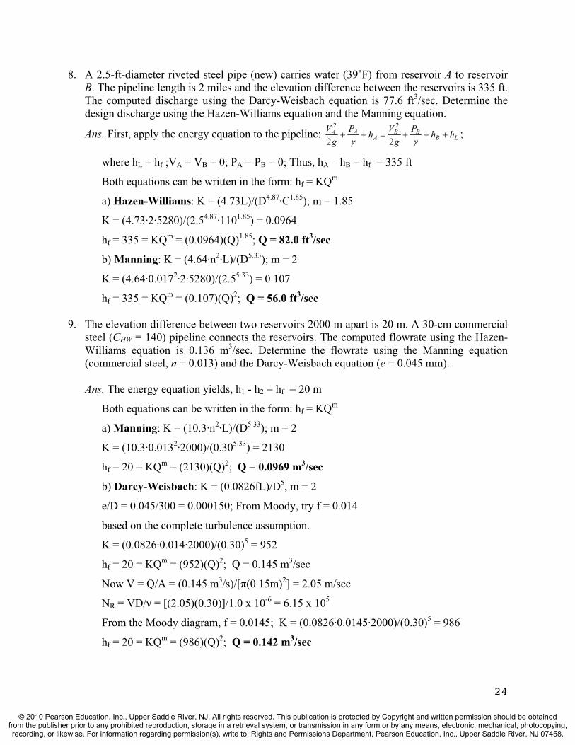
8. A 2.5-ft-diameter riveted steel pipe (new) carries water (39˚F) from reservoir A to reservoir B. The pipeline length is 2 miles and the elevation difference between the reservoirs is 335 ft. The computed discharge using the Darcy-Weisbach equation is 77.6 ft3/sec. Determine the design discharge using the Hazen-Williams equation and the Manning equation.
Ans. First, apply the energy equation to the pipeline; LBBB
AAA hhP
gVhP
gV
22
22;
where hL = hf ;VA = VB = 0; PA = PB = 0; Thus, hA – hB = hf = 335 ft
Both equations can be written in the form: hf = KQm
a) Hazen-Williams: K = (4.73L)/(D4.87·C1.85); m = 1.85
K = (4.73·2·5280)/(2.54.87·1101.85) = 0.0964
hf = 335 = KQm = (0.0964)(Q)1.85; Q = 82.0 ft3/sec
b) Manning: K = (4.64·n2·L)/(D5.33); m = 2
K = (4.64·0.0172·2·5280)/(2.55.33) = 0.107
hf = 335 = KQm = (0.107)(Q)2; Q = 56.0 ft3/sec
9. The elevation difference between two reservoirs 2000 m apart is 20 m. A 30-cm commercial steel (CHW = 140) pipeline connects the reservoirs. The computed flowrate using the Hazen-Williams equation is 0.136 m3/sec. Determine the flowrate using the Manning equation (commercial steel, n = 0.013) and the Darcy-Weisbach equation (e = 0.045 mm).
Ans. The energy equation yields, h1 - h2 = hf = 20 m
Both equations can be written in the form: hf = KQm
a) Manning: K = (10.3·n2·L)/(D5.33); m = 2
K = (10.3·0.0132·2000)/(0.305.33) = 2130
hf = 20 = KQm = (2130)(Q)2; Q = 0.0969 m3/sec
b) Darcy-Weisbach: K = (0.0826fL)/D5, m = 2
e/D = 0.045/300 = 0.000150; From Moody, try f = 0.014
based on the complete turbulence assumption.
K = (0.0826·0.014·2000)/(0.30)5 = 952
hf = 20 = KQm = (952)(Q)2; Q = 0.145 m3/sec
Now V = Q/A = (0.145 m3/s)/[ (0.15m)2] = 2.05 m/sec
NR = VD/ = [(2.05)(0.30)]/1.0 x 10-6 = 6.15 x 10⁵
From the Moody diagram, f = 0.0145; K = (0.0826·0.0145·2000)/(0.30)5 = 986
hf = 20 = KQm = (986)(Q)2; Q = 0.142 m3/sec
24
© 2010 Pearson Education, Inc., Upper Saddle River, NJ. All rights reserved. This publication is protected by Copyright and written permission should be obtainedfrom the publisher prior to any prohibited reproduction, storage in a retrieval system, or transmission in any form or by any means, electronic, mechanical, photocopying,recording, or likewise. For information regarding permission(s), write to: Rights and Permissions Department, Pearson Education, Inc., Upper Saddle River, NJ 07458.

10. The pressure head drop across a short section of an 8-inch-pipeline (PVC) is 12 ft. The pipeline section contains a globe valve and another valve of some kind that is open but not labeled. Determine what kind of valve it is if the flow rate is 2.74 cfs. Assume that the friction loss is negligible in the short pipe segment.
Ans. Assuming friction losses are negligible, the headloss for the pipe section is:
hL= [Kv(globe)+Kv(unknown)](V)2/2g; & V = Q/A = (2.74 ft3/s)/[ {(1/3)ft}2] = 7.85 ft/sec;
thus; 12 ft = [10 + Kv(unknown)] (7.85 ft/s)2/2·32.2 ft/s2
Kv(unknown) = 2.54; It is likely a check valve (swing type)
11. Determine the maximum discharge obtainable in a 3.5-ft-diameter commercial steel penstock that brings water from a mountain reservoir to a hydroelectric power plant. The penstock entrance is squared-edged and 100-ft below the reservoir's water surface. It is 1500 ft long (and drops 750 ft in elevation), contains a globe valve, and discharges into the atmosphere.
Ans. Applying the energy eq’n from the reservoir surface (1) to the penstock outlet (2) yields;
LhhPg
VhPg
V2
22
21
12
1
22; where P1 = P2 = 0; V1 = 0; h2 = 0; and
hL = hf + [ K](V2/2g). Thus h1 = [1 + f(L/D) + K](V2/2g);
where V2 = V (pipe V); Ke = 0.5; Kv = 10.0; and h1 = 100 ft + 750 ft = 850 ft
Assuming complete turbulence for the first trial: e/D = (0.00015ft)/(3.5ft) = 0.0000429
thus; f = 0.010, and h1 = 850 = [1+0.010(1500/3.5)+0.5+10](V2/2g); V = 58.9 ft/sec;
NR = DV/ = [(3.5)(58.9)]/(1.08x10-5) = 1.91 x 10⁷; From Moody; new f = 0.010; (ok)
Q = V·A = (58.9 ft/s)[ (1.75ft)2] = 567 ft3/sec
12. An oil flow rate of 0.012 m3/s is required in an industrial process. The flow system includes a pressure tank pushing the oil through 200 m of new ductile iron pipe (DIP; 15 cm diameter) to point B (atmospheric pressure) as shown in the figure below. The surface of the fluid in the tank (1) is at elevation 100 m and the end of the pipe (2) is at elevation 106 m. What air pressure will be needed over the fluid to produce the requisite flow? (S.G.(oil) = 0.84, = 2.03 x 10⁻⁶ m2/s, and = 0.00012m.)
1
2
Air
25
© 2010 Pearson Education, Inc., Upper Saddle River, NJ. All rights reserved. This publication is protected by Copyright and written permission should be obtainedfrom the publisher prior to any prohibited reproduction, storage in a retrieval system, or transmission in any form or by any means, electronic, mechanical, photocopying,recording, or likewise. For information regarding permission(s), write to: Rights and Permissions Department, Pearson Education, Inc., Upper Saddle River, NJ 07458.
Ans. Applying the energy eq’n from the oil surface (1) to the pipe outlet (2) yields;
LhhPg
VhPg
V2
22
21
12
1
22; where P2 = 0; V1 = 0; and hL = hf + [ K](V2/2g); Thus
h1 + P1/ = h2 + [1 + f(L/D) + K](V2/2g); where V2 = V (pipe V) and Ke = 0.5;
e/D = 0.00012m/0.15m = 0.00080; V = Q/A = (0.012 m3/s)/[ (0.075m)2] = 0.679 m/s
NR = DV/ = [(0.15m)(0.679m/s)]/(2.03x10-6m2/s) = 5.02 x 10⁴; thus f = 0.024, and
100m + P1/ = 106m + [1 + 0.024(200/0.15) + 0.5]{(0.679m/s)2/2·9.81m/s2}
P1/ = 6.79 m; P1 = (6.79 m)(0.84)(9790 N/m3) = 55,800 N/m2 (Pascals) = 55.8 kPa
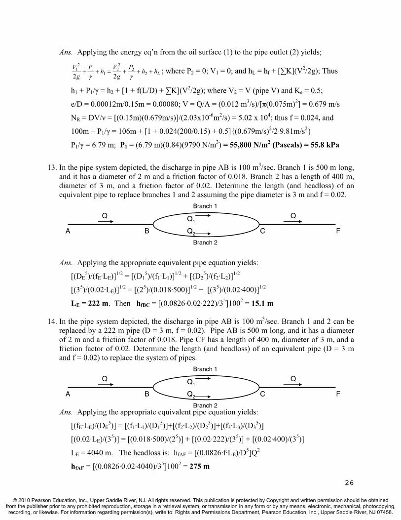
13. In the pipe system depicted, the discharge in pipe AB is 100 m3/sec. Branch 1 is 500 m long, and it has a diameter of 2 m and a friction factor of 0.018. Branch 2 has a length of 400 m, diameter of 3 m, and a friction factor of 0.02. Determine the length (and headloss) of an equivalent pipe to replace branches 1 and 2 assuming the pipe diameter is 3 m and f = 0.02.
26
A B C F
Q QQ1
Q2
Branch 1
Branch 2
Ans. Applying the appropriate equivalent pipe equation yields:
[(DE5)/(fE·LE)]1/2 = [(D1
5)/(f1·L1)]1/2 + [(D25)/(f2·L2)]1/2
[(35)/(0.02·LE)]1/2 = [(25)/(0.018·500)]1/2 + [(35)/(0.02·400)]1/2
LE = 222 m. Then hfBC = [(0.0826·0.02·222)/35]1002 = 15.1 m
14. In the pipe system depicted, the discharge in pipe AB is 100 m3/sec. Branch 1 and 2 can be replaced by a 222 m pipe (D = 3 m, f = 0.02). Pipe AB is 500 m long, and it has a diameter of 2 m and a friction factor of 0.018. Pipe CF has a length of 400 m, diameter of 3 m, and a friction factor of 0.02. Determine the length (and headloss) of an equivalent pipe (D = 3 m and f = 0.02) to replace the system of pipes.
A B C F
Ans. Applying the appropriate equivalent pipe equation yields:
Q QQ1
Q2
Branch 1
Branch 2
[(fE·LE)/(DE5)] = [(f1·L1)/(D1
5)]+[(f2·L2)/(D25)]+[(f3·L3)/(D3
5)]
[(0.02·LE)/(35)] = [(0.018·500)/(25)] + [(0.02·222)/(35)] + [(0.02·400)/(35)]
LE = 4040 m. The headloss is: hfAF = [(0.0826·f·LE)/D5]Q2
hfAF = [(0.0826·0.02·4040)/35]1002 = 275 m
© 2010 Pearson Education, Inc., Upper Saddle River, NJ. All rights reserved. This publication is protected by Copyright and written permission should be obtainedfrom the publisher prior to any prohibited reproduction, storage in a retrieval system, or transmission in any form or by any means, electronic, mechanical, photocopying,recording, or likewise. For information regarding permission(s), write to: Rights and Permissions Department, Pearson Education, Inc., Upper Saddle River, NJ 07458.

TEST QUESTIONS & PROBLEMS - CHAPTER #4
Short Answer Questions
1. Why is an iterative procedure required to determine the size (diameter) of a pipeline needed to pass a given flow from one reservoir to another if you are provided with the reservoir water surface elevations, pipe length, and the pipe material (assuming the Darcy-Weisbach equation is used for friction loss)? Ans. The difference in reservoir surface elevations is equal to the head loss, and the greatest
loss is generally friction loss. The friction factor is unknown and depends on the relative roughness and possibly the Reynold’s number. Both of these parameters require the diameter, which is unknown, and thus an iterative procedure is necessary.
2. (T or F) When a pipeline connects two reservoirs, the difference in water surface elevations is equal to the total head loss (friction and all minor losses). Ans. True
3. Sketch the energy grade line (EGL) and hydraulic grade line (HGL) for the pipeline below.
Ans. Sketch the EGL and HGL such that a) both start & end at the reservoir surfaces, b) the minor losses (entrance, valve, expansion, and exit) are accounted for with an abrupt drop in the EGL and HGL; c) the EGL and HGL are parallel lines, but the separation distance (i.e., the velocity head, V2/2g) is less for the larger pipe, and d) the slope of the EGL, which represents the friction loss over length, is greater for the smaller pipe.
4. Sketch the energy grade line (EGL) and hydraulic grade line (HGL) for the pipeline below.
Valve
27
© 2010 Pearson Education, Inc., Upper Saddle River, NJ. All rights reserved. This publication is protected by Copyright and written permission should be obtainedfrom the publisher prior to any prohibited reproduction, storage in a retrieval system, or transmission in any form or by any means, electronic, mechanical, photocopying,recording, or likewise. For information regarding permission(s), write to: Rights and Permissions Department, Pearson Education, Inc., Upper Saddle River, NJ 07458.

Ans. Sketch the EGL and HGL such that a) both start & end at the reservoir surfaces, b) the minor losses (entrance, contraction, expansion, exit) are accounted for with an abrupt drop in the EGL and HGL; c) the EGL and HGL are parallel lines, but the separation distance (i.e., the velocity head, V2/2g) is less for the larger pipes, and d) the slope of the EGL, which represents the friction loss over length, is greater for the smaller pipe.
5. Define cavitation. Ans. The formation of vapor pockets in pipelines which occurs when the pressure drop falls below the vapor pressure of water. This is often followed by vapor collapse when normal pressure return downstream and is accompanied by damaging vibration and sound waves.
6. What two locations in pipelines are likely places for cavitation to occur? Ans. The suction side of pumps and the high point in siphons or pipelines.
7. (T or F) Cavitation can occur on the discharge side of pumps or when a pipeline rises above the hydraulic grade line (HGL).Ans. False – on the suction side of pumps.
8. Do all siphons encounter negative pressure at their summit points? Prove your answer by using an energy grade line (EGL) and hydraulic grade line (HGL) sketch. Ans. Yes, the pipe center line rises above the HGL as seen in the sketch below.
9. Sketch the energy grade line (EGL) and hydraulic grade line (HGL) for the pipeline below.
Ans. Sketch the EGL and HGL such that a) both start & end at the reservoir surfaces, b) the minor losses (entrance, bends, exit) are accounted for with an abrupt drop in the EGL and HGL; c) the EGL and HGL are parallel lines, and d) the pump adds a significant boost (abrupt rise) to the EGL.
Pump
-P/
EGLHGL
28
© 2010 Pearson Education, Inc., Upper Saddle River, NJ. All rights reserved. This publication is protected by Copyright and written permission should be obtainedfrom the publisher prior to any prohibited reproduction, storage in a retrieval system, or transmission in any form or by any means, electronic, mechanical, photocopying,recording, or likewise. For information regarding permission(s), write to: Rights and Permissions Department, Pearson Education, Inc., Upper Saddle River, NJ 07458.

10. (T or F) Pumps add energy to a fluid primarily in the form of increased velocity head. Ans. False – increased pressure head.
11. (T or F) Negative gage pressure in a pipeline occurs whenever the pipe rises above the hydraulic grade line (HGL). Ans. True
12. Solving the classical 3-reservoir problem generally does not require the determination of a) friction losses b) minor losses c) mass balance d) energy balance Ans. (b) – minor losses are often ignored because they are small when compared to friction.
13. In the classical 3-reservoir problem, we are typically solving for the three pipe flow rates. What other unknown enters the analysis and what four equations are used in the solution? Ans. The fourth unknown is the total head at the junction. The four solution equations include
three energy balances between the reservoirs and the junction (which includes a friction loss equation) and mass balance at the junction.
14. Solution of the classical 3-reservoir problem relies on all of the following principles except a) conservation of momentum b) conservation of energyc) conservation of mass d) friction loss equation (e.g., Darcy-Weisbach) Ans. (a)
15. When solving the classical 3-reservoir problem, a trial energy elevation at the junction may be needed. What is a good first estimate and why? Ans. The middle reservoir’s water surface elevation is a good first estimate; it reduces the
number of computations and the result will indicate whether a higher or lower estimate is needed. Thus, the direction of flow (to or from) the middle reservoir is established.
16. All of the following principles are applied to the classical 3-reservoir problem except b) conservation of momentum b) conservation of energy c) Bernoulli principle d) conservation of mass e) friction losses e) minor losses Ans. (a) and (c) are not used, and (e) is generally not used, although it could be.
17. (T or F) Two major assumptions used in the solution of the classical 3-reservoir problem include negligible minor losses in the pipes and a negligible velocity head at the junction.Ans. True
18. Starting with the Darcy-Weisbach equation, determine the value of K in hf = KQ2.Ans. hf =f(L/D)(V2/2g) = f(L/D)[Q2/(2g A2)] =[fL/(2g·D·A2)] Q2; K=[fL/(2g·D·A2)]
19. Give two advantages of having the grid system in pipe networks rather than a dendritic (tree-like) system in distributing water to urban customers. Ans. Fewer people are without service if a line breaks (valves can be closed on either side of
the leak). In a dendritic system, everyone downstream of the break is without water until it is fixed. Also, water is less likely to stagnate in a grid system.
29
© 2010 Pearson Education, Inc., Upper Saddle River, NJ. All rights reserved. This publication is protected by Copyright and written permission should be obtainedfrom the publisher prior to any prohibited reproduction, storage in a retrieval system, or transmission in any form or by any means, electronic, mechanical, photocopying,recording, or likewise. For information regarding permission(s), write to: Rights and Permissions Department, Pearson Education, Inc., Upper Saddle River, NJ 07458.
20. What principles are used to determine flow rates in a water distribution system (network)? c) conservation of momentum b) conservation of energy c) Bernoulli principle d) conservation of mass e) friction losses e) minor losses Ans. (b), (d), and (e) are used; (f) is generally not although it could be..
21. In solving a pipe network problem, one condition which must be satisfied is mass balance at each junction ( Q = 0). What other condition must be satisfied? Ans. Between any two junctions, the total head loss is independent of the path taken based on the conservation of energy (loop equation).
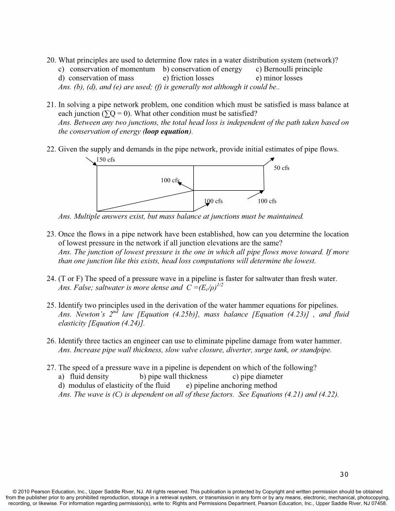
22. Given the supply and demands in the pipe network, provide initial estimates of pipe flows. 150 cfs
Ans. Multiple answers exist, but mass balance at junctions must be maintained.
23. Once the flows in a pipe network have been established, how can you determine the location of lowest pressure in the network if all junction elevations are the same? Ans. The junction of lowest pressure is the one in which all pipe flows move toward. If more than one junction like this exists, head loss computations will determine the lowest.
24. (T or F) The speed of a pressure wave in a pipeline is faster for saltwater than fresh water.Ans. False; saltwater is more dense and C =(Ec/ )1/2
25. Identify two principles used in the derivation of the water hammer equations for pipelines.Ans. Newton’s 2nd law [Equation (4.25b)], mass balance [Equation (4.23)] , and fluid elasticity [Equation (4.24)].
26. Identify three tactics an engineer can use to eliminate pipeline damage from water hammer. Ans. Increase pipe wall thickness, slow valve closure, diverter, surge tank, or standpipe.
27. The speed of a pressure wave in a pipeline is dependent on which of the following? a) fluid density b) pipe wall thickness c) pipe diameterd) modulus of elasticity of the fluid e) pipeline anchoring method Ans. The wave is (C) is dependent on all of these factors. See Equations (4.21) and (4.22).
100 cfs
50 cfs
100 cfs
100 cfs
30
© 2010 Pearson Education, Inc., Upper Saddle River, NJ. All rights reserved. This publication is protected by Copyright and written permission should be obtainedfrom the publisher prior to any prohibited reproduction, storage in a retrieval system, or transmission in any form or by any means, electronic, mechanical, photocopying,recording, or likewise. For information regarding permission(s), write to: Rights and Permissions Department, Pearson Education, Inc., Upper Saddle River, NJ 07458.

Problems
1. Water (20˚C) flows at the rate of 0.015 m3/sec from reservoir A to reservoir B through two concrete (e = 0.32 mm) pipes connected in series. If L1 = 800 m, D1 = 16 cm, L2 = 200 m, and D2 = 8 cm, determine the difference in water surface elevations. The coefficient of contraction is 0.36 and assume fully turbulent flow (i.e., f depends on e/D only).
Ans. Apply the energy eq’n; LBBB
AAA hhP
gVhP
gV
22
22; VA = VB = PA = PB = 0,
hL = hf + [ K](V)2/2g; where Ke = 0.5, Kc = 0.36, and Kd = 1.0. Therefore,
hA - hB = [f(L/D)1 + K](V12/2g) + [f(L/D)2 + K](V2
2/2g)
hA - hB = [f1(800/0.16) + 0.5](V12/2g) + [f2(200/0.08) + 0.36 + 1.0](V2
2/2g)
V1 = Q/A= (0.015 m3/s)/[( /4)(0.16 m)2]= 0.746 m/sec; e/D1= 0.32mm/160mm = 0.002
V2 = Q/A = (0.015 m3/s)/[( /4)(0.08 m)2] = 2.98 m/sec; e/D2= 0.32mm/80mm = 0.004
From the Moody diagram: f1 = 0.0235; and f2 = 0.0285; Substituting we have
hA - hB = [0.0235(800/0.16)+0.5][(0.746)2/2g)+[0.0285(200/0.08)+1.36][(2.98)2/2g]
hA = 36.2 m
2. If the pressure at point 1 in the figure below is 50.9 kPa and the water flow in the 4-inch pipe (0.102 m) is 10.1 litres/sec (20°C),, determine the pressure P0 at reservoir A.
Ans. Apply the energy eq’n; LAAA hhP
gVhP
gV
11
21
2
22; and VA = 0, V1 = V (pipeline V),
hL = hf + [ K](V)2/2g; hA= 10 m, h1= 7 m, PA= P0, and P1/ = 50.9/9.79 = 5.20m. Thus,
P0/ = P1/ + h1 - hA + [1+f(L/D)+ K](V2/2g) = 5.2 m - 3 m - [1+f(L/D)+ K](V2/2g)
V = Q/A = (0.0101 m3/s)/[( /4)(0.102 m)2] = 1.24 m/s; e/D = 0.045/102 = 0.000441
NR = DV/ = [(0.102m)(1.24 m/s)]/(1.00 x 10-6 m2/s) = 1.26 x 10⁵; hence f = 0.02, and,
P0/ = 2.2 m - [1+0.02(10/0.102)+0.5+12.0][(1.24)2/2·9.81] = 0.988m; P0 = 9.67 kPa
31
© 2010 Pearson Education, Inc., Upper Saddle River, NJ. All rights reserved. This publication is protected by Copyright and written permission should be obtainedfrom the publisher prior to any prohibited reproduction, storage in a retrieval system, or transmission in any form or by any means, electronic, mechanical, photocopying,recording, or likewise. For information regarding permission(s), write to: Rights and Permissions Department, Pearson Education, Inc., Upper Saddle River, NJ 07458.

3. Water (at 10 C with a = 1.31 x 10⁻⁶ m2/sec) flows from reservoir A (surface elevation 100 m) through a 2.25-m-diameter, concrete pipe to reservoir B (surface elevation 88 meters). If the two reservoirs are 17 km apart, determine the flow rate taking into account minor losses. How much would the flowrate change if minor losses were neglected?
Ans. Apply the energy eq’n; LBBB
AAA hhP
gVhP
gV
22
22; where VA = VB = PA = PB = 0,
hL = hf + [ K](V)2/2g; Ke = 0.5, Kd = 1.0, and hA – hB = 12 m. Thus,
12 m = [f(1700m/2.25m) + 1.5](V2/2g); where V is pipe V.
Assume complete turbulence for the first trial; for concrete (avg):
e/D = 0.36mm/2250mm = 0.00016; thus; f = 0.013 and solving energy eq’n
12 m = [0.013(17,000m/2.25m) + 1.5](V2/2g); V = 1.54 m/sec. Now solve for NR,
NR = DV/ = [(2.25)(1.54)]/(1.31x10-6) = 2.65 x 10⁶; From Moody; new f = 0.0135;
12 m = [0.0135(17,000m/2.25m) + 1.5](V2/2g); V = 1.51 m/sec. Same “f” results.
Thus, Q = V·A = (1.51 m/s)[( /4)(2.25m)2] = 6.00 m3/sec;
Without minor losses;
12 m = [0.0135(17,000m/2.25m)](V2/2g); V = 1.52 m/sec. Q = 6.04 m3/sec
4. The elevation difference between two reservoirs, 25 km apart, is 80 m. Ductile iron pipes (DIPs) are used to transport water between the two reservoirs. (a) Determine the pipe diameter that will carry a discharge of 200 /sec. (b) With the computed pipe diameter, determine the elevation difference between the two reservoirs if the flow rate must be increased to 250 /sec. Assume a water temperature of 20°C and include minor losses.
Ans. a)Apply the energy eq’n; LBBB
AAA hhP
gVhP
gV
22
22; where VA = VB = PA = PB = 0,
hL = hf + [ K](V)2/2g; Ke = 0.5, Kd = 1.0, hA–hB = 80 m, & V = Q/A = 0.255/D2. Thus,
80 m = [f(25000/D) + 1.5]·[(0.255/D2)2/2g]. Assume D = 0.5 m, thus V = 1.02 m/s,
e/D = 0.12/500 = 0.00024; NR = DV/ = [(0.5)(1.02)]/(1.00x10-6) = 5.10 x 10⁵; and from
the Moody diagram, f = 0.016; solving energy e’qn for new D;
80 m = [0.016(25000/D) + 1.5]·[(0.255/D2)2/2g]; D = 0.44 m, so change size to this and
V = 1.32 m/s, e/D = 0.00027; NR = [(0.44)(1.32)]/(1.00x10-6) = 5.81 x 10⁵; f = 0.016; ck
Therefore, D = 0.44 m.
b) If the flow rate increase is req’d with this new pipe, V = Q/A = 0.25/[( /4)·(0.44m)2] =
1.64 m/s, NR = DV/ = [(0.44)(1.64)]/(1.00x10-6) = 7.22 x 10⁵; and f = 0.0155 and
hA–hB = [0.0155(25000/0.44) + 1.5]·[(1.64)2/2g] = 121 m
32
© 2010 Pearson Education, Inc., Upper Saddle River, NJ. All rights reserved. This publication is protected by Copyright and written permission should be obtainedfrom the publisher prior to any prohibited reproduction, storage in a retrieval system, or transmission in any form or by any means, electronic, mechanical, photocopying,recording, or likewise. For information regarding permission(s), write to: Rights and Permissions Department, Pearson Education, Inc., Upper Saddle River, NJ 07458.
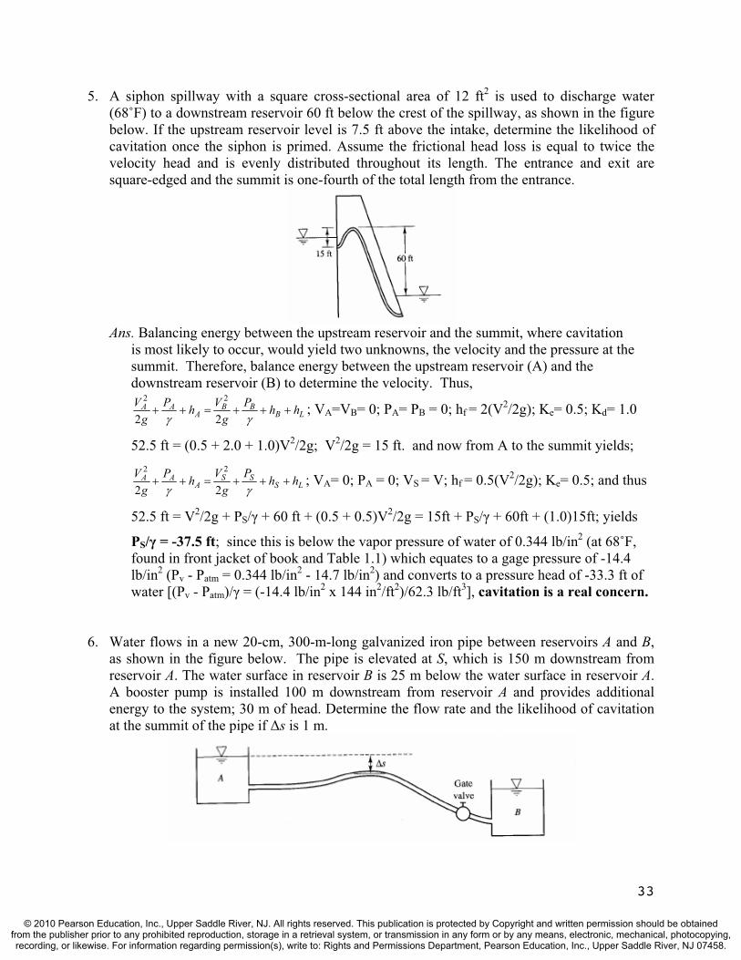
5. A siphon spillway with a square cross-sectional area of 12 ft2 is used to discharge water (68˚F) to a downstream reservoir 60 ft below the crest of the spillway, as shown in the figure below. If the upstream reservoir level is 7.5 ft above the intake, determine the likelihood of cavitation once the siphon is primed. Assume the frictional head loss is equal to twice the velocity head and is evenly distributed throughout its length. The entrance and exit are square-edged and the summit is one-fourth of the total length from the entrance.
Ans. Balancing energy between the upstream reservoir and the summit, where cavitation is most likely to occur, would yield two unknowns, the velocity and the pressure at the summit. Therefore, balance energy between the upstream reservoir (A) and the downstream reservoir (B) to determine the velocity. Thus,
LBBB
AAA hhP
gVhP
gV
22
22; VA=VB= 0; PA= PB = 0; hf = 2(V2/2g); Ke= 0.5; Kd= 1.0
52.5 ft = (0.5 + 2.0 + 1.0)V2/2g; V2/2g = 15 ft. and now from A to the summit yields;
LSSS
AAA hhP
gVhP
gV
22
22; VA= 0; PA = 0; VS = V; hf = 0.5(V2/2g); Ke= 0.5; and thus
52.5 ft = V2/2g + PS/ + 60 ft + (0.5 + 0.5)V2/2g = 15ft + PS/ + 60ft + (1.0)15ft; yields
PS/ = -37.5 ft; since this is below the vapor pressure of water of 0.344 lb/in2 (at 68˚F,found in front jacket of book and Table 1.1) which equates to a gage pressure of -14.4 lb/in2 (Pv - Patm = 0.344 lb/in2 - 14.7 lb/in2) and converts to a pressure head of -33.3 ft of water [(Pv - Patm)/ = (-14.4 lb/in2 x 144 in2/ft2)/62.3 lb/ft3], cavitation is a real concern.
6. Water flows in a new 20-cm, 300-m-long galvanized iron pipe between reservoirs A and B,as shown in the figure below. The pipe is elevated at S, which is 150 m downstream from reservoir A. The water surface in reservoir B is 25 m below the water surface in reservoir A.A booster pump is installed 100 m downstream from reservoir A and provides additional energy to the system; 30 m of head. Determine the flow rate and the likelihood of cavitation at the summit of the pipe if s is 1 m.
33
© 2010 Pearson Education, Inc., Upper Saddle River, NJ. All rights reserved. This publication is protected by Copyright and written permission should be obtainedfrom the publisher prior to any prohibited reproduction, storage in a retrieval system, or transmission in any form or by any means, electronic, mechanical, photocopying,recording, or likewise. For information regarding permission(s), write to: Rights and Permissions Department, Pearson Education, Inc., Upper Saddle River, NJ 07458.

Ans. Balancing energy between the upstream (A) and downstream (B) reservoirs yields LBPA hHHH ; where HP = 30m; HA- HB = 25 m; and
hL = hf + [ K](V)2/2g; where Ke = 0.5, Kv = 0.15, Kd = 1.0. Therefore,
25m + 30m = [f(300/0.2) + 1.65)V2/2g; where V is pipe V. Assume complete turbulence
e/D = 0.15mm/200mm = 0.00075; thus; f 0.0185 & solve energy eq’n
55m = [0.0185(300/0.2) + 1.65](V2/2g); V = 6.06 m/sec. Now we can solve for NR,
NR = DV/ = [(0.2)(6.06)]/(1.00x10-6) = 1.21 x 10⁶; From Moody; new f = 0.0185; OK
Thus, Q = V·A = (6.06 m/s)[( /4)(0.2m)2] = 0.190 m3/sec (190 L/sec)
Now balancing energy from A to the summit yields;
LSSS
PAAA hhP
gVHhP
gV
22
22; where VA = PA = 0; VS = V; hA – hs = 1.0 m; and
hL = hf + [ K](V)2/2g; where Ke = 0.5. Therefore,
1.0m + 30m = (6.06)2/2g + PS/ + [0.0185(150/0.2) + 0.5)(6.06)2/2g; PS/ = 2.22 m
Since the gage pressure is positive, there is no likelihood of cavitation.
7. A pump will be used to remove 50 cfs of water from an aquifer and transport it to a water treatment plant. The 24-in. pipe is made of high density polyethylene (HDPE) with an entrance screen (K = 2.5). Determine the maximum height above the aquifer that the pump could be placed without encountering cavitation (using an allowable pressure head of –24 ft).
Ans. Balancing energy from aquifer A to the suction side of the pump yields;
LSSS
AAA hhP
gVhP
gV
22
22; VA= PA= 0; VS = V; PA/ = -24 ft; let hA= 0 (datum); and
hL= hf + [ K](V)2/2g; Ke= 2.5; assume hf= 0; & V=Q/A= 50/[ (1.0)2] = 15.9 ft/s. Thus,
0.0 ft = (15.9)2/2g + (-24) + hS + [2.5](15.9)2/2g; and hS = 10.3 ft
8. Determine the flow in each pipe in the figure below if all of the pipes are made of the same material with e = 0.05 mm and water temperature at 20°C ( = 1.00 x 10⁻⁶). Try an initial energy level at the junction of 82 m, and go through one complete iteration of the solution including a comment on your second trial energy level at the junction.
34
© 2010 Pearson Education, Inc., Upper Saddle River, NJ. All rights reserved. This publication is protected by Copyright and written permission should be obtainedfrom the publisher prior to any prohibited reproduction, storage in a retrieval system, or transmission in any form or by any means, electronic, mechanical, photocopying,recording, or likewise. For information regarding permission(s), write to: Rights and Permissions Department, Pearson Education, Inc., Upper Saddle River, NJ 07458.
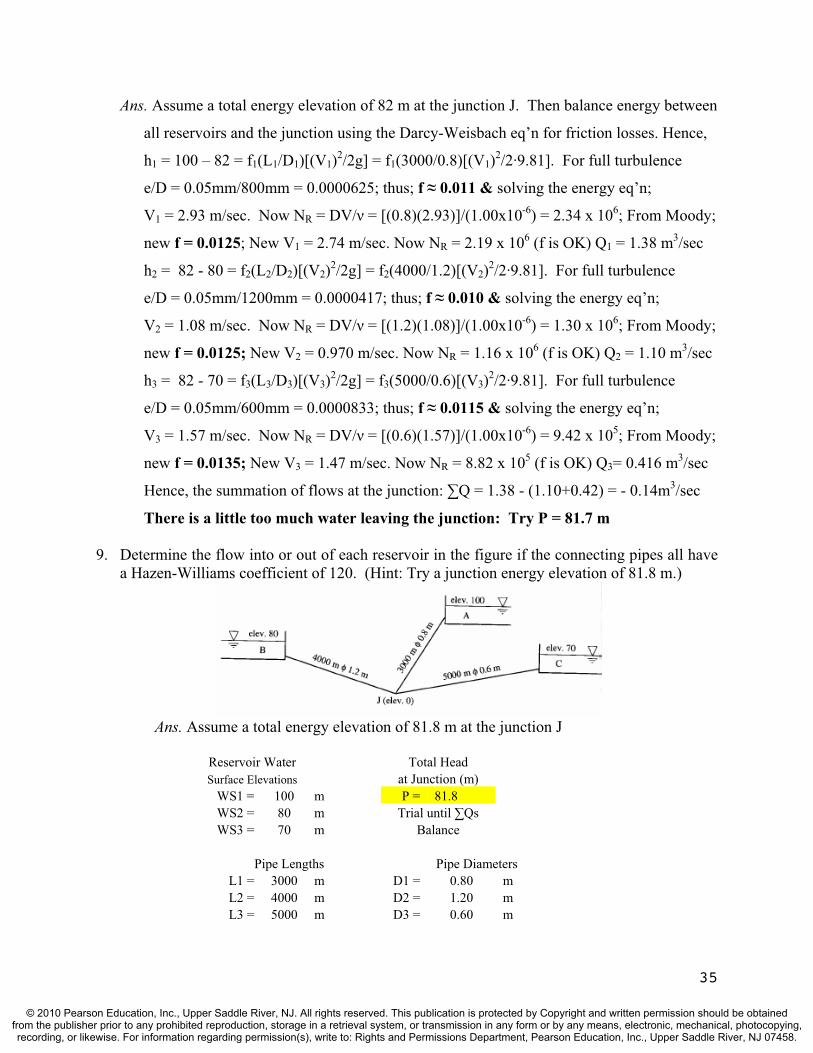
Ans. Assume a total energy elevation of 82 m at the junction J. Then balance energy between
all reservoirs and the junction using the Darcy-Weisbach eq’n for friction losses. Hence,
h1 = 100 – 82 = f1(L1/D1)[(V1)2/2g] = f1(3000/0.8)[(V1)2/2·9.81]. For full turbulence
e/D = 0.05mm/800mm = 0.0000625; thus; f 0.011 & solving the energy eq’n;
V1 = 2.93 m/sec. Now NR = DV/ = [(0.8)(2.93)]/(1.00x10-6) = 2.34 x 10⁶; From Moody;
new f = 0.0125; New V1 = 2.74 m/sec. Now NR = 2.19 x 10⁶ (f is OK) Q1 = 1.38 m3/sec
h2 = 82 - 80 = f2(L2/D2)[(V2)2/2g] = f2(4000/1.2)[(V2)2/2·9.81]. For full turbulence
e/D = 0.05mm/1200mm = 0.0000417; thus; f 0.010 & solving the energy eq’n;
V2 = 1.08 m/sec. Now NR = DV/ = [(1.2)(1.08)]/(1.00x10-6) = 1.30 x 10⁶; From Moody;
new f = 0.0125; New V2 = 0.970 m/sec. Now NR = 1.16 x 10⁶ (f is OK) Q2 = 1.10 m3/sec
h3 = 82 - 70 = f3(L3/D3)[(V3)2/2g] = f3(5000/0.6)[(V3)2/2·9.81]. For full turbulence
e/D = 0.05mm/600mm = 0.0000833; thus; f 0.0115 & solving the energy eq’n;
V3 = 1.57 m/sec. Now NR = DV/ = [(0.6)(1.57)]/(1.00x10-6) = 9.42 x 10⁵; From Moody;
new f = 0.0135; New V3 = 1.47 m/sec. Now NR = 8.82 x 10⁵ (f is OK) Q3= 0.416 m3/sec
Hence, the summation of flows at the junction: Q = 1.38 - (1.10+0.42) = - 0.14m3/sec
There is a little too much water leaving the junction: Try P = 81.7 m
9. Determine the flow into or out of each reservoir in the figure if the connecting pipes all have a Hazen-Williams coefficient of 120. (Hint: Try a junction energy elevation of 81.8 m.)
Ans. Assume a total energy elevation of 81.8 m at the junction J
Reservoir Water Total Head Surface Elevations at Junction (m)
WS1 = 100 m P = 81.8 WS2 = 80 m Trial until Qs WS3 = 70 m Balance
Pipe Lengths Pipe Diameters L1 = 3000 m D1 = 0.80 mL2 = 4000 m D2 = 1.20 mL3 = 5000 m D3 = 0.60 m
35
© 2010 Pearson Education, Inc., Upper Saddle River, NJ. All rights reserved. This publication is protected by Copyright and written permission should be obtainedfrom the publisher prior to any prohibited reproduction, storage in a retrieval system, or transmission in any form or by any means, electronic, mechanical, photocopying,recording, or likewise. For information regarding permission(s), write to: Rights and Permissions Department, Pearson Education, Inc., Upper Saddle River, NJ 07458.

Pipe# CHW hf S* Rh** V*** Q
(m) (m) (m/sec) (m3/sec)1 120 18.2 0.00607 0.20 2.35 1.18 2 120 1.8 0.00045 0.30 0.74 0.84 3 120 11.8 0.00236 0.15 1.18 0.33
* S = hf/L (friction slope or EGL slope in this case) If P < WS2; Q = 1.69 ** Rh = D/4 (Equation 3.26)
*** V = 0.849CRh0.63S0.54 (Equation 3.27) If P > WS2; Q = 0.01
10. A small branching pipe system distributes water to three holding tanks. Pipe 1 contains a valve that is partly closed, and only allows 1.0 cfs of water through it with a head loss of 3.60 feet. Estimate the length of Pipe 2 given the following water surface (WS) elevation and pipe data (lengths, diameters, and Hazen-Williams coefficients):
WS1 = 4020 ft L1 = 1000 ft D1 = 1.0 ft C1 = 80 WS2 = 4018 ft L2 = ? D2 = 10 in. C2 = 100 WS3 = 4000 ft L3 = 5000 ft D3 = 1.0 ft C3 = 120
The total energy elevation at the junction is 4015 ft.
WS1
Ans. The flow to the junction from reservoir 1 (in Pipe 1) is 1.0 cfs. Using the Hazen-
Williams equation, determine the flow in Pipe 3.
Q3 = VA = (1.318CHWRh0.63S0.54 )(A) = (1.318)(120)(1ft/4)0.63(15/5000)0.54 ( /4)(1ft)2
Q3 = 2.25 cfs; Therefore, the flow in Pipe 2 is 2.25 – 1.0 = 1.25 cfs toward J. Hence,
Q2 = 1.25 cfs = (1.318)(100)[(10/12)ft/4]0.63[3/(L2)]0.54 ( /4)[(10/12)ft]2; L2 = 873 ft
J Pipe 2
Pipe 1
WS3
WS2 Reservoir 1
PReservoir 2
Pipe 3 Reservoir 3
36
© 2010 Pearson Education, Inc., Upper Saddle River, NJ. All rights reserved. This publication is protected by Copyright and written permission should be obtainedfrom the publisher prior to any prohibited reproduction, storage in a retrieval system, or transmission in any form or by any means, electronic, mechanical, photocopying,recording, or likewise. For information regarding permission(s), write to: Rights and Permissions Department, Pearson Education, Inc., Upper Saddle River, NJ 07458.

11. Fill in the blanks for the partially completed pipe network solution table given below.
Loop Pipe Q(m3/sec)
K(sec2/m5)
hf(m)
hf/Q(sec/m2)
New Q(m3/sec)
C 8 ? ? 1.30 31.7 ?9 0.025 4880 3.05 122.0 ?
10 (0.095) 775 ? ? ?4 0.153 131 3.07 20.1 ?
Ans. The table can be filled in using the equation hf = KQ2 and the flow adjustment equation:
sec/m 001.06.731.200.1227.312
99.607.305.330.1//2
3
ccfcccfc
fccfc
QhQhhh
Q
Loop Pipe Q(m3/sec)
K(sec2/m5)
hf(m)
hf/Q(sec/m2)
New Q(m3/sec)
C 8 0.041 773 1.30 31.7 0.0409 0.025 4880 3.05 122.0 0.024
10 (0.095) 775 (6.99) (73.6) (0.096)4 0.153 131 3.07 20.1 0.152
12. From the pipe network data below, determine the flow in pipes CE and DE, and the pressurehead HE. Also determine the pressure (in psi) at E if the ground elevation is 650 ft.
Pipe Flow(ft3/sec)
Length(ft)
Diameter (in.)
K(sec2/ft5)
AB 15.35 1000 12 0.424BC 5.76 1500 8 1.510BD 9.55 1200 12 1.100DC 2.29 1500 6 9.530CE ? 2000 12 1.540DE ? 1000 8 0.949
HA = 1000 ft
A C
B
EQE = ? HE = ?
D
37
© 2010 Pearson Education, Inc., Upper Saddle River, NJ. All rights reserved. This publication is protected by Copyright and written permission should be obtainedfrom the publisher prior to any prohibited reproduction, storage in a retrieval system, or transmission in any form or by any means, electronic, mechanical, photocopying,recording, or likewise. For information regarding permission(s), write to: Rights and Permissions Department, Pearson Education, Inc., Upper Saddle River, NJ 07458.

Ans. Use the principles of mass balance and energy balance to determine flows and heads:
QDE = QBD - QDC = 9.55 – 2.29 = 7.26 cfs; QCE = QBC + QDC = 5.76 + 2.29 = 8.05 cfs
HE = HA – hf(AB) – hf(BD) - hf(DE) ; hf(AB) = (kQ2)AB = (0.424)(15.35)2 = 100 ft
hf(BD) = (kQ2)BD = (1.100)(9.5)2 = 100 ft; hf(DE) = (kQ2)DE = (0.949)(7.26)2 = 50.0 ft
HE = 1000 – 100 – 100 – 50 = 750 ft; (P/ )E = HE - ZE = 750 – 650 = 100 ft. (Assuming
V2/2g = 0); and PE = (100 ft)(62.3 lbs/ft3)(1 ft2/144 in.2); PE = 43.3 psi
13. Pipe flows are estimated in the pipe network below based on mass balance principles. These flow rates are given in the table with the direction specified (e.g., AB indicates flow from A to B). Proceed through one iteration of the Hardy Cross algorithm for each loop. Also, if the total head at A is 50 feet, determine the pressure (psi) at E (elev = 0) using your results.
Ans. The original data provided is in black; the information requested is in bold red.
Loop Pipe Q (cfs)
K hf(ft)
hf /Q New Q (cfs)
1 AB 1.00 14.25 14.25 14.25 0.90BC 0.20 7.00 0.28 1.40 0.10AC (0.8) 14.25 (9.12) (11.40) 0.90
Q = [ (hfc) - (hfcc)] / [2( (hfc/Qc) + (hfcc/Qcc))] = [(14.25+0.28)-(9.12)] / [2(14.25+1.40)+(11.40))] = +0.10
Loop Pipe Q (cfs)
K hf(ft)
hf /Q New Q (cfs)
2 BD 0.80 14.25 9.12 11.40 0.70DE 0.20 7.00 0.28 1.40 0.10BC (0.10) 7.00 (0.07) (0.70) 0.20CE (0.60) 14.25 (5.13) (8.55) 0.70
Q = [(9.12+0.28)-(0.07+5.13)] / [2(11.40+1.40)+(0.70+8.55))] = +0.10
HE = HA – hf(AC) – hf(CE) = 50 – 9.12 – 5.13 = 35.8 ft; (P/ )E = HE - ZE = 35.8 ft.
(Assuming V2/2g = 0); and PE = (35.8 ft)(62.3 lbs/ft3)(1 ft2/144 in.2); PE = 15.5 psi
0.4 cfs
1.8 cfsB D
A
C E
0.8 cfs
0.6 cfs
1 2
38
© 2010 Pearson Education, Inc., Upper Saddle River, NJ. All rights reserved. This publication is protected by Copyright and written permission should be obtainedfrom the publisher prior to any prohibited reproduction, storage in a retrieval system, or transmission in any form or by any means, electronic, mechanical, photocopying,recording, or likewise. For information regarding permission(s), write to: Rights and Permissions Department, Pearson Education, Inc., Upper Saddle River, NJ 07458.
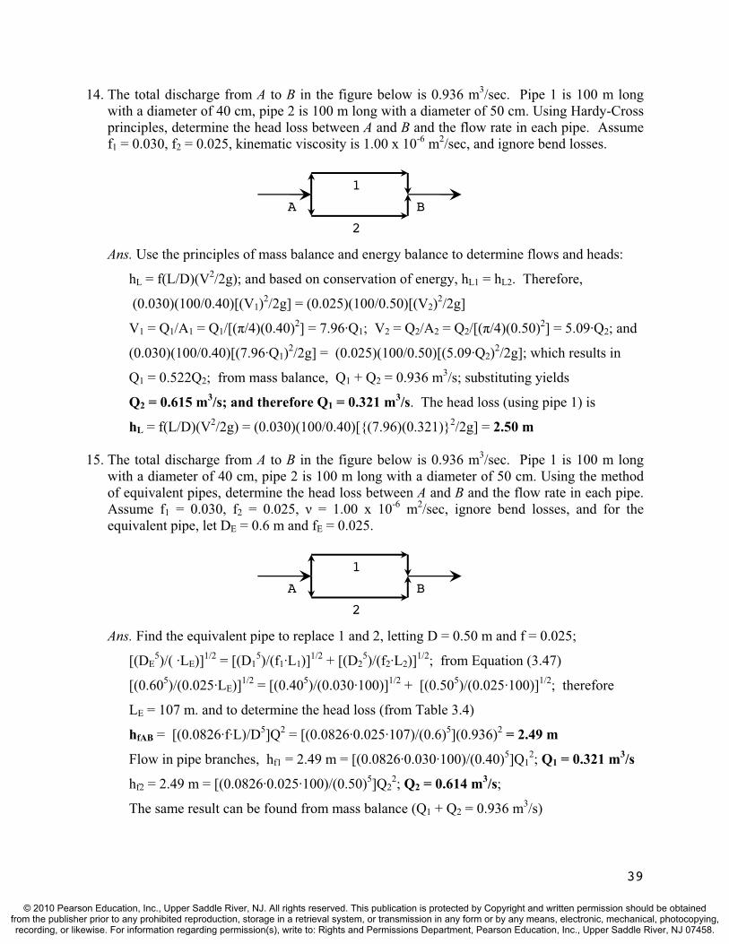
14. The total discharge from A to B in the figure below is 0.936 m3/sec. Pipe 1 is 100 m long with a diameter of 40 cm, pipe 2 is 100 m long with a diameter of 50 cm. Using Hardy-Cross principles, determine the head loss between A and B and the flow rate in each pipe. Assume f1 = 0.030, f2 = 0.025, kinematic viscosity is 1.00 x 10⁻⁶ m2/sec, and ignore bend losses.
Ans. Use the principles of mass balance and energy balance to determine flows and heads:
hL = f(L/D)(V2/2g); and based on conservation of energy, hL1 = hL2. Therefore,
(0.030)(100/0.40)[(V1)2/2g] = (0.025)(100/0.50)[(V2)2/2g]
V1 = Q1/A1 = Q1/[( /4)(0.40)2] = 7.96·Q1; V2 = Q2/A2 = Q2/[( /4)(0.50)2] = 5.09·Q2; and
(0.030)(100/0.40)[(7.96·Q1)2/2g] = (0.025)(100/0.50)[(5.09·Q2)2/2g]; which results in
Q1 = 0.522Q2; from mass balance, Q1 + Q2 = 0.936 m3/s; substituting yields
Q2 = 0.615 m3/s; and therefore Q1 = 0.321 m3/s. The head loss (using pipe 1) is
hL = f(L/D)(V2/2g) = (0.030)(100/0.40)[{(7.96)(0.321)}2/2g] = 2.50 m
15. The total discharge from A to B in the figure below is 0.936 m3/sec. Pipe 1 is 100 m long with a diameter of 40 cm, pipe 2 is 100 m long with a diameter of 50 cm. Using the method of equivalent pipes, determine the head loss between A and B and the flow rate in each pipe. Assume f1 = 0.030, f2 = 0.025, = 1.00 x 10⁻⁶ m2/sec, ignore bend losses, and for the equivalent pipe, let DE = 0.6 m and fE = 0.025.
1
2
BA
1
2
BA
Ans. Find the equivalent pipe to replace 1 and 2, letting D = 0.50 m and f = 0.025;
[(DE5)/( ·LE)]1/2 = [(D1
5)/(f1·L1)]1/2 + [(D25)/(f2·L2)]1/2; from Equation (3.47)
[(0.605)/(0.025·LE)]1/2 = [(0.405)/(0.030·100)]1/2 + [(0.505)/(0.025·100)]1/2; therefore
LE = 107 m. and to determine the head loss (from Table 3.4)
hfAB = [(0.0826·f·L)/D5]Q2 = [(0.0826·0.025·107)/(0.6)5](0.936)2 = 2.49 m
Flow in pipe branches, hf1 = 2.49 m = [(0.0826·0.030·100)/(0.40)5]Q12; Q1 = 0.321 m3/s
hf2 = 2.49 m = [(0.0826·0.025·100)/(0.50)5]Q22; Q2 = 0.614 m3/s;
The same result can be found from mass balance (Q1 + Q2 = 0.936 m3/s)
39
© 2010 Pearson Education, Inc., Upper Saddle River, NJ. All rights reserved. This publication is protected by Copyright and written permission should be obtainedfrom the publisher prior to any prohibited reproduction, storage in a retrieval system, or transmission in any form or by any means, electronic, mechanical, photocopying,recording, or likewise. For information regarding permission(s), write to: Rights and Permissions Department, Pearson Education, Inc., Upper Saddle River, NJ 07458.
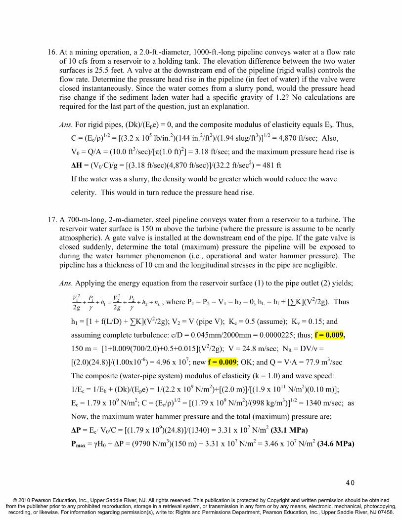
16. At a mining operation, a 2.0-ft.-diameter, 1000-ft.-long pipeline conveys water at a flow rate of 10 cfs from a reservoir to a holding tank. The elevation difference between the two water surfaces is 25.5 feet. A valve at the downstream end of the pipeline (rigid walls) controls the flow rate. Determine the pressure head rise in the pipeline (in feet of water) if the valve were closed instantaneously. Since the water comes from a slurry pond, would the pressure head rise change if the sediment laden water had a specific gravity of 1.2? No calculations are required for the last part of the question, just an explanation.
Ans. For rigid pipes, (Dk)/(Epe) = 0, and the composite modulus of elasticity equals Eb. Thus,
C = (Ec/ )1/2 = [(3.2 x 10⁵ lb/in.2)(144 in.2/ft2)/(1.94 slug/ft3)]1/2 = 4,870 ft/sec; Also,
V0 = Q/A = (10.0 ft3/sec)/[ (1.0 ft)2] = 3.18 ft/sec; and the maximum pressure head rise is
H = (V0·C)/g = [(3.18 ft/sec)(4,870 ft/sec)]/(32.2 ft/sec2) = 481 ft
If the water was a slurry, the density would be greater which would reduce the wave
celerity. This would in turn reduce the pressure head rise.
17. A 700-m-long, 2-m-diameter, steel pipeline conveys water from a reservoir to a turbine. The reservoir water surface is 150 m above the turbine (where the pressure is assume to be nearly atmospheric). A gate valve is installed at the downstream end of the pipe. If the gate valve is closed suddenly, determine the total (maximum) pressure the pipeline will be exposed to during the water hammer phenomenon (i.e., operational and water hammer pressure). The pipeline has a thickness of 10 cm and the longitudinal stresses in the pipe are negligible.
Ans. Applying the energy equation from the reservoir surface (1) to the pipe outlet (2) yields;
LhhPg
VhPg
V2
22
21
12
122
; where P1 = P2 = V1 = h2 = 0; hL = hf + [ K](V2/2g). Thus
h1 = [1 + f(L/D) + K](V2/2g); V2 = V (pipe V); Ke = 0.5 (assume); Kv = 0.15; and
assuming complete turbulence: e/D = 0.045mm/2000mm = 0.0000225; thus; f = 0.009,
150 m = [1+0.009(700/2.0)+0.5+0.015](V2/2g); V = 24.8 m/sec; NR = DV/ =
[(2.0)(24.8)]/(1.00x10-6) = 4.96 x 10⁷; new f = 0.009; OK; and Q = V·A = 77.9 m3/sec
The composite (water-pipe system) modulus of elasticity (k = 1.0) and wave speed:
1/Ec = 1/Eb + (Dk)/(Epe) = 1/(2.2 x 109 N/m2)+[(2.0 m)]/[(1.9 x 1011 N/m2)(0.10 m)];
Ec = 1.79 x 10⁹ N/m2; C = (Ec/ )1/2 = [(1.79 x 10⁹ N/m2)/(998 kg/m3)]1/2 = 1340 m/sec; as
Now, the maximum water hammer pressure and the total (maximum) pressure are:
P = Ec· V0/C = [(1.79 x 10⁹)(24.8)]/(1340) = 3.31 x 10⁷ N/m2 (33.1 MPa)
Pmax = H0 + P = (9790 N/m3)(150 m) + 3.31 x 10⁷ N/m2 = 3.46 x 10⁷ N/m2 (34.6 MPa)
40
© 2010 Pearson Education, Inc., Upper Saddle River, NJ. All rights reserved. This publication is protected by Copyright and written permission should be obtainedfrom the publisher prior to any prohibited reproduction, storage in a retrieval system, or transmission in any form or by any means, electronic, mechanical, photocopying,recording, or likewise. For information regarding permission(s), write to: Rights and Permissions Department, Pearson Education, Inc., Upper Saddle River, NJ 07458.

41
18. A simple surge tank is installed in a pipeline to protect an electric generator. The circular concrete tunnel between the reservoir and the surge tank is 1600 m long and 1.5 m in diameter. If the maximum flow is 6 m3/sec, compute the maximum water rise if the surge tank is 6 m in diameter.
Ans. Neglecting minor losses, determine the head loss and the pipeline friction factor.
hL = hf = f(L/D)(V2/2g); where V = Q/A = (6.0 m3/sec)/[( /4)(1.5m)2] = 3.40 m/sec;
e/D = 0.36mm/1500mm = 0.00024; NR= [(1.5)(3.40)]/(1.00x10-6) = 5.1 x 10⁶; f = 0.0145
hL = hf = f(L/D)(V2/2g) = [0.0145(1600/1.5)[(3.40)2/2g] = 9.11 m; and now
Kf = hL/V2 = (9.11 m)/[(3.40 m/sec)2] = 0.788 sec2/m; and the damping factor is
= (LA)/(2gKfAs) = [(1600m)(1.77m2)]/[2(9.81m/sec2)(0.788 sec2/m)( /4)(6.0m)2] = 6.48 m;
To determine ymax, use: (ymax + hL)/( ) = ln [( )/( - ymax)]; or substituting
(ymax + 9.11m)/(6.48 m) = ln [(6.48 m)/(6.48 m – ymax)]; ymax 5.84 m
19. A surge tank is being designed to retard the water mass in a 3450-ft long pipeline, 6.5 ft in diameter. The design discharge is 460 cfs and the pipe material is smooth concrete. Determine the diameter of the surge tank if the water in the tank is allowed to rise to an elevation 16.5 ft above the feeding reservoir after the flow is suddenly stopped.
Ans. Neglecting minor losses, determine the head loss and the pipeline friction factor.
hL = hf = f(L/D)(V2/2g); where V = Q/A = (460 ft3/sec)/[( /4)(6.5 ft)2] = 13.9 ft/sec;
e/D = 0.0006ft/6.5ft = 0.000092; NR = [(6.5)(13.9)]/(1.08 x 10-5) = 8.37 x 10⁶; f = 0.012
hL = hf = f(L/D)(V2/2g) = [0.012(3450/6.5)[(13.9)2/2g] = 19.1 ft; and thus:
Kf = hL/V2 = (19.1 ft)/[(13.9 ft/sec)2] = 0.0989 sec2/ft.
Now determine the damping factor using ymax: (ymax + hL)/( ) = ln [( )/( - ymax)]; or
(16.5 ft + 19.1 ft)/( ) = ln [( )/( – 16.5 ft)]; 19.9 ft;
and solving for As from = (LA)/(2gKfAs) yields
19.9 ft = [(3450 ft)(33.2 ft2)]/[2(32.2 ft/sec2)(0.0989 sec2/ft)(As)];
As = 904 ft2; or Ds = 33.9 ft; which is too large to be practical.
Consider allowing a larger water surface rise or go to a slow valve closure.
© 2010 Pearson Education, Inc., Upper Saddle River, NJ. All rights reserved. This publication is protected by Copyright and written permission should be obtainedfrom the publisher prior to any prohibited reproduction, storage in a retrieval system, or transmission in any form or by any means, electronic, mechanical, photocopying,recording, or likewise. For information regarding permission(s), write to: Rights and Permissions Department, Pearson Education, Inc., Upper Saddle River, NJ 07458.

TEST QUESTIONS & PROBLEMS - CHAPTER #5
Short Answer Questions
1. Define the physical meaning of Vo, o, and o in the centrifugal pump vector diagram.
Ans. Vo is the absolute velocity of the water leaving the impellor, o is the angle of the impeller at exit, and o is the velocity of the water if the impellor was not rotating (or the relative velocity of the water with respect to the vanes).
2. The fundamental principle of the centrifugal pump was first demonstrated by: a) Manning b) Chezy c) Darcy-Weisbach d) Hazen-Williams e) Demour f) Wojak-Vieck Ans. (e) - Demour is the correct answer.
3. What is the difference between a turbo hydraulic pump and a positive displacement pump? Ans. Turbo-hydraulic pumps move fluids with a rotating vane or another moving fluid.
Positive-displacement pumps move fluids strictly by precise machine displacements
4. Which variables represent the impeller speed, the exit velocity, and the angle of the impeller in the vector diagram below?
Ans. represents the impellor speed, Vo represents the exit velocity of the water, and o is the angle of the impeller.
5. Using the equations for motor efficiency and pump efficiency, derive the expression for overall efficiency of a pump system (sometimes called the wire to water efficiency).Ans. ep = Po/Pi and em = Pi/Pm. Therefore, e = ep·em = (Po/Pi)(Pi/Pm) = Po/Pm.
6. Which of the following represents units of power? a) work/time b) hp (horsepower) c) kW (kilowatts) d) dynes Ans. (a), (b), and (c) all represent appropriate units of power.
7. (T or F) Pumps add energy to a fluid primarily in the form of increased pressure. Ans. True
42
© 2010 Pearson Education, Inc., Upper Saddle River, NJ. All rights reserved. This publication is protected by Copyright and written permission should be obtainedfrom the publisher prior to any prohibited reproduction, storage in a retrieval system, or transmission in any form or by any means, electronic, mechanical, photocopying,recording, or likewise. For information regarding permission(s), write to: Rights and Permissions Department, Pearson Education, Inc., Upper Saddle River, NJ 07458.

8. (T or F) Pumps add energy to a pipeline; thus the outflow from a pump exceeds the inflow.Ans. False – this would violate the mass balance principle.
9. Propeller blades may be mounted on the same axis of rotation in a common housing to form a multistage propeller pump. What is the advantage of this configuration? Ans. Propeller pumps are appropriate for high capacity flow, but they can not overcome
large heads. By staging propellers, they can pump water over a greater elevation difference.
10. (T or F) Propeller pumps move a lot of water, but they do not overcome a lot of head. Ans. True.
11. Describe two differences between an propeller (axial-flow) pump and a centrifugal pump. Is the theory of both based on the principle of impulse-momentum? Ans. Centrifugal flow is radial and axial flow is not. Centrifugal flow is based on angular
momentum and axial flow is based on linear momentum.
12. (T or F) Jet pumps are often used in combination with centrifugal pumps and have a high efficiency.Ans. False – they have very low efficiencies.
13. Centrifugal pump curves (Hp vs. Q) start at a high head, low flow rate and trend downward with increasing flow. What is the reason for this? Ans. Pumps add energy to overcome a position head difference and pipe losses. As the flow
rate increases, so do the losses so less position head can be overcome. Alternatively, as the position head difference decreases, more energy is available for flow.
14. On centrifugal pump curves (Hp vs. Q), the point where Q = 0 and Hp = Hp(max) is called thea) shut-off head b) rated capacity c) brake horsepower d) match point e) no idea!! Ans. (a) is the correct answer.
15. Draw a typical pump characteristic curve and label the axes. Then draw a typical system curve on the same graph. Label the match point and the shut-off head. Now draw a typical efficiency curve on the same graph. Ans. See Figure (5.10) in the book. The pump head at zero discharge is the shut-off head.
16. Centrifugal pump characteristic curves are a plot of Q vs. which of the followinga) pump head b) rated capacity c) brake horsepower d) efficiency e) friction loss Ans. (a), (c), and (d).
17. What is the difference between the match point and the shut-off head? Ans. The match point is the intersection of the pump characteristic curve (Hp vs. Q) and the
system curve. The pump head at zero discharge on the pump characteristic curve is the shut-off head.
43
© 2010 Pearson Education, Inc., Upper Saddle River, NJ. All rights reserved. This publication is protected by Copyright and written permission should be obtainedfrom the publisher prior to any prohibited reproduction, storage in a retrieval system, or transmission in any form or by any means, electronic, mechanical, photocopying,recording, or likewise. For information regarding permission(s), write to: Rights and Permissions Department, Pearson Education, Inc., Upper Saddle River, NJ 07458.

18. Which of the following statements about pumps are false? a) Pumps operate under maximum efficiency over a very broad range of discharges.b) The shut-off head is the height water can be raised but produce no flow. c) Pump discharge increases with decreasing pump head. d) Two identical pumps in parallel on one discharge line will double the flow rate. e) Pump selection involves superimposing a system curve on a pump characteristic curve. Ans. (a) and (d) are false.
19. Sketch the energy grade line (EGL) and hydraulic grade line (HGL) for the pipeline below.
Pump
Ans. Sketch the EGL and HGL such that a) both start & end at the reservoir surfaces, b) the minor losses (entrance, bends, exit) are accounted for with an abrupt drop in the EGL and HGL; c) the EGL and HGL are parallel lines, and d) the pump adds a significant boost (abrupt rise) to the EGL.
20. Draw a typical pump characteristic curve (Hp vs. Q) and label the axes. On the same graph, sketch the characteristic curve for the system of identical pumps depicted below if valve A is closed and valves B and C are open.
Ans. By closing valve A you have pumps in parallel, and flows should be doubled on the characteristic curve. See Figure (5.13) in the book.
21. Draw a typical pump characteristic curve (Hp vs. Q) and label the axes. On the same graph, sketch the characteristic curve for the system of identical pumps depicted in Question 20 if valve A is open and valves B and C are closed.Ans. By closing valves B and C you have pumps in series, and pump heads should be doubled
on the characteristic curve. See Figure (5.13) in the book.
44
© 2010 Pearson Education, Inc., Upper Saddle River, NJ. All rights reserved. This publication is protected by Copyright and written permission should be obtainedfrom the publisher prior to any prohibited reproduction, storage in a retrieval system, or transmission in any form or by any means, electronic, mechanical, photocopying,recording, or likewise. For information regarding permission(s), write to: Rights and Permissions Department, Pearson Education, Inc., Upper Saddle River, NJ 07458.
22. Draw a typical pump characteristic curve (Hp vs. Q) and label the axes. On the same graph, sketch the characteristic curve for the system of identical pumps depicted in Question 20 if valve A is open and valves B and C are replaced by two more identical pumps making a four pump arrangement. Ans. This arrangement produces two pumps in series on each line, producing parallel lines.
Both pump heads and pump flows should be doubled on the characteristic curve.
23. (T or F) By placing two identical pumps in a pipeline in a parallel configuration, you can expect to double the discharge.Ans. False – losses will increase for the increased flow and use some of the pumps energy.
24. (T or F) A pump is placed in a branching pipeline and is required to pump water from a supply reservoir to two receiving reservoirs. The total discharge will be split between the two pipes such that an equal amount of head is added to each of the two pipelines. Ans. True
25. How is a pipe network analysis modified to incorporate a pump? Ans. The energy equation for the loop containing the pump is modified to incorporate the
energy added by the pump.
26. Many factors contribute to the loss of pressure on the suction side of pumps. Of those listed here, which does the designer of pumps have the most control over to avoid cavitation. a) position of the pump b) screen loss c) friction loss d) entrance loss e) “b” and “d” Ans. (a) is the correct answer.
27. Give three examples of head losses that can be encountered on the suction side of pumps that may contribute to the loss of pressure and cavitation problems. Ans. Entrance loss, screen loss, friction loss, other minor losses (i.e., bends, valves, etc.).
28. (T or F) To avoid cavitation in a pump, one of the few parameters that the designer has much control over is the position of the pump.Ans. True.
29. To avoid cavitation in a pump, one of the few items that a designer has control over is thea) vapor pressure b) velocity head c) position of the pump d) suction line head losses Ans. (c) is the correct answer.
30. Where is cavitation most likely to occur in a pump installation? Ans. A common site of cavitation is near the tips of the impeller vanes where the velocity is
very high and pressure energy is converted to kinetic energy.
31. The maximum velocity near the tip of impeller vanes is an important parameter in assessing pump cavitation potential. It is normally supplied by the pump manufacturers using the term: a) total suction head b) tip velocity c) cavitation parameter d) net positive suction head Ans. (e) is the correct answer.
45
© 2010 Pearson Education, Inc., Upper Saddle River, NJ. All rights reserved. This publication is protected by Copyright and written permission should be obtainedfrom the publisher prior to any prohibited reproduction, storage in a retrieval system, or transmission in any form or by any means, electronic, mechanical, photocopying,recording, or likewise. For information regarding permission(s), write to: Rights and Permissions Department, Pearson Education, Inc., Upper Saddle River, NJ 07458.
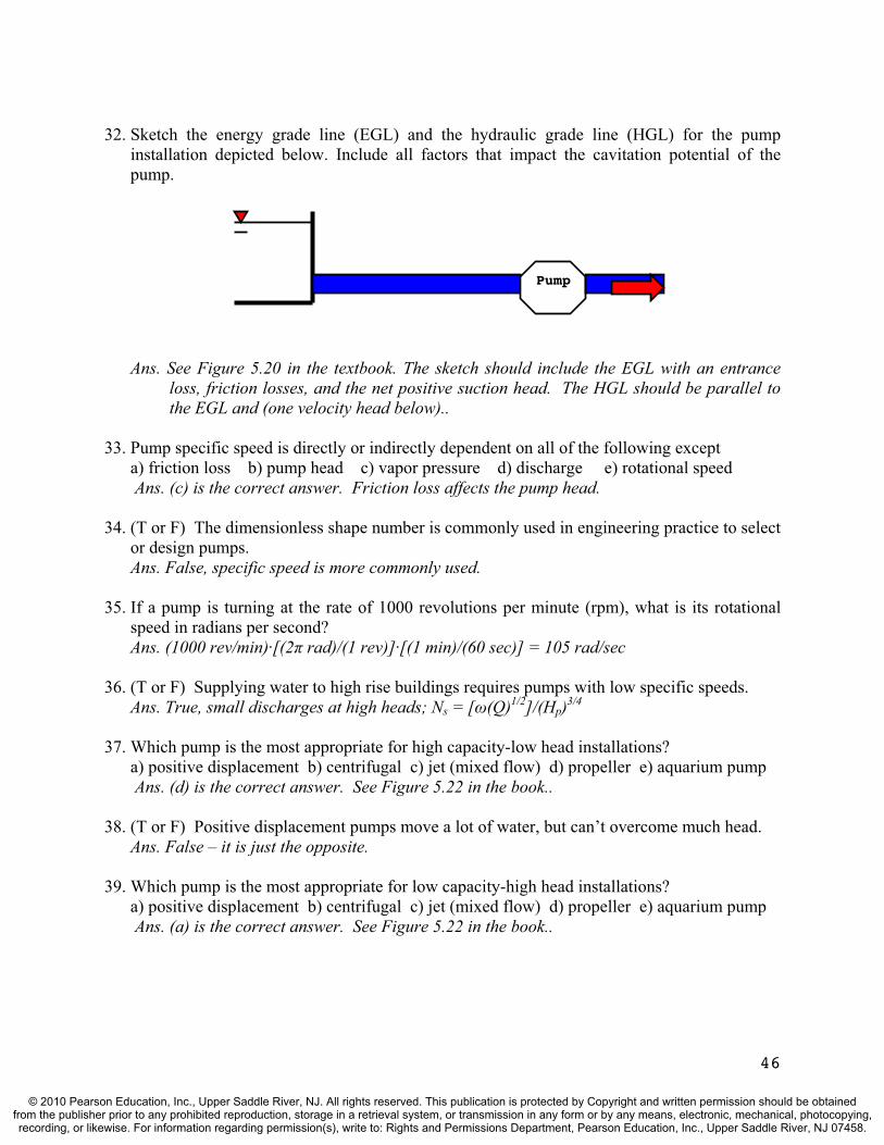
32. Sketch the energy grade line (EGL) and the hydraulic grade line (HGL) for the pump installation depicted below. Include all factors that impact the cavitation potential of the pump.
Pump
Ans. See Figure 5.20 in the textbook. The sketch should include the EGL with an entrance loss, friction losses, and the net positive suction head. The HGL should be parallel to the EGL and (one velocity head below)..
33. Pump specific speed is directly or indirectly dependent on all of the following excepta) friction loss b) pump head c) vapor pressure d) discharge e) rotational speed Ans. (c) is the correct answer. Friction loss affects the pump head.
34. (T or F) The dimensionless shape number is commonly used in engineering practice to select or design pumps.Ans. False, specific speed is more commonly used.
35. If a pump is turning at the rate of 1000 revolutions per minute (rpm), what is its rotational speed in radians per second? Ans. (1000 rev/min)·[(2 rad)/(1 rev)]·[(1 min)/(60 sec)] = 105 rad/sec
36. (T or F) Supplying water to high rise buildings requires pumps with low specific speeds. Ans. True, small discharges at high heads; Ns = [ (Q)1/2]/(Hp)3/4
37. Which pump is the most appropriate for high capacity-low head installations? a) positive displacement b) centrifugal c) jet (mixed flow) d) propeller e) aquarium pump Ans. (d) is the correct answer. See Figure 5.22 in the book..
38. (T or F) Positive displacement pumps move a lot of water, but can’t overcome much head. Ans. False – it is just the opposite.
39. Which pump is the most appropriate for low capacity-high head installations? a) positive displacement b) centrifugal c) jet (mixed flow) d) propeller e) aquarium pump Ans. (a) is the correct answer. See Figure 5.22 in the book..
46
© 2010 Pearson Education, Inc., Upper Saddle River, NJ. All rights reserved. This publication is protected by Copyright and written permission should be obtainedfrom the publisher prior to any prohibited reproduction, storage in a retrieval system, or transmission in any form or by any means, electronic, mechanical, photocopying,recording, or likewise. For information regarding permission(s), write to: Rights and Permissions Department, Pearson Education, Inc., Upper Saddle River, NJ 07458.
Problems
1. Determine the flow rate of a water pump that overcomes an energy head of 65 ft. A 750-kW motor drives the pump with an efficiency of 77% and the pump operates with an efficiency of 85%. (Note: 1 kW = 1.34 horsepower (hp) and 1 hp = 550 ft-lb/sec)
Ans. Pi = em·Pm = (0.77)(750 kW)(1.34 hp/1 kW) = 774 hp;
Po = ep·Pi = (0.85)(774 hp){(550 ft-lb/sec)/1 hp} = 3.62 x 105 ft-lb/sec
Po = 3.62 x 105 ft-lb/sec = QHP = (62.3 lb/ft3)(Q)(65 ft); Q = 89.4 ft3/sec
2. A 26-kW motor with 78% efficiency drives a centrifugal pump delivery 68 /sec against a head of 24 m. Determine the pump efficiency.
Ans. Po = QHP = (9.79 kN/m3)(0.068 m3/sec)(24 m) = 16.0 kN·m/sec = 16.0 kW
e = Po/Pm = (16.0 kW)/(26 kW) = 0.615 (61.5%) and since e = ep·em
ep = e/em = (0.615)/(0.78) = 0.788 (78.8 %)
3. A centrifugal pump impeller has an inlet diameter of 50 cm and outlet diameter of 150 cm. With i = 135° and o = 150°, the pump is rotating at an angular velocity of 100 rad/sec. The impeller has uniform thickness of 30 cm. If the radial velocity component ri is the same magnitude as the tangential velocity component Vti, calculate the discharge of the pump and the power input to the pump.
Ans. From the problem statement, ri = Vti. Thus, from Fig. 5.3 we see that i = 45˚. Also,
ui = ri = (100 rad/sec)(0.25 m) = 25.0 m/sec, and since that i = 45˚ and i = 135˚;
Vti = Vri = ri = ti; and therefore, ri = ui/2 = 12.5 m/sec. Also,
Q = Ai ri = (2 )(ri)(B)( ri) = (2 )(0.25m)(0.30m)(12.5 m/sec) = 5.89 m3/sec
ti = ri/tan 135˚ = - ri = -12.5 m/sec; Vi = [ ri2 + (ui + ti)2]½
Vi = [(12.5)2 + (25.0 - 12.5)2]½ = 17.7 m/sec. Also, uo = ro = 75.0 m/sec, and
ro = Q/Ao = (5.89 m3/sec)/[(2 )(0.75m)(0.30m)] = 4.17 m/sec
to = ro/tan 150˚ = (4.17 m/sec)/(tan 150˚) = -7.22 m/sec; Vo = [ ro2 + (uo + to)2]½
Vo = [(4.17)2 + (75.0 - 7.22)2]½ = 67.9 m/sec. o = tan-1 [ ro/(uo + to)] = 3.52˚
Pi = Q [roVocos( o) - riVicos( i)] = (998 kg/m3)(5.89 m3/sec)(100 rad/sec)·
[(0.75m)(67.9 m/s)cos 3.52˚ - (0.25m)(17.7 m/s)cos 45˚] = 2.81 x 10⁷ N-m/sec
Pi = 2.81 x 10⁷ N-m/sec(1 kW/1000 N-m/sec) = 28,100 kW
47
© 2010 Pearson Education, Inc., Upper Saddle River, NJ. All rights reserved. This publication is protected by Copyright and written permission should be obtainedfrom the publisher prior to any prohibited reproduction, storage in a retrieval system, or transmission in any form or by any means, electronic, mechanical, photocopying,recording, or likewise. For information regarding permission(s), write to: Rights and Permissions Department, Pearson Education, Inc., Upper Saddle River, NJ 07458.

4. The absolute velocity of water exiting a centrifugal pump impeller is 120 ft/sec. The angle of the exiting water is 55° measured from a radial line originating at the center of the pump impeller. If the impeller radius is 1.5 ft and the width of the vane is 0.5 ft, determine the angular momentum (torque) of the flow leaving the pump.
Ans. The torque on the exiting flow is T = QroVocos( o) where Q = A ro and from Fig. 5.3,
ro = Vosin( o); o = 90˚- 55˚ = 35˚ from problem statement, thus
ro = Vosin( o) = (120 ft/sec)(sin 35˚) = 68.8 ft/sec
Q = A ro = 2 ro(B) ro = 2 (1.5 ft)(0.5 ft)(68.8 ft/s) = 324 ft3/sec; and
T = QroVocos( o) = (1.94 slug/ft3)(324 ft3/sec)(1.5 ft)(120 ft/s)(cos 35˚) = 9,270 ft·lb
5. Consider a pump-pipeline system that delivers flow from reservoir A to B with EA = 120 ft and EB = 100 ft. The pipe has a length of L = 12,800 ft, diameter of D = 2 ft, and a Hazen Williams coefficient of CHW = 100. The pump characteristics are tabulated below and minor losses (in feet) accumulate at the rate of 0.001*Q2 where Q is the flow in cfs. Estimate the flow rate in the pipeline by filling in the solution table below.
Q Hp hf hminor Hs HSH(cfs) Pump (ft) (ft) (ft) (ft) (ft)
0 300.020 225.525 187.530 138.035 79.5
Ans. HSH = Hs+ hL; where hL = hf + hminor and Hs = EB - EA= 100 - 120 = -20 ft.
Using the Hazen Williams friction equation (Table 3.4); , and 85.1KQh f
K = (4.73·L)/[(D)4.87(C)1.85] = (4.73·12,800)/[(2.0)4.87(100)1.85] = 0.413. The solution table
is below with the last four columns filled in. By interpolation from the table, the
pipeline flow is roughly Q = 27.1 cfs and Hp 167 ft. (Q = 26.5 cfs to 27.5 cfs is ok)
Q Hp hf hminor Hs HSH(cfs) Pump (ft) (ft) (ft) (ft) (ft)
0 300.0 0.0 0.00 -20.0 -20.020 225.5 105.4 0.40 -20.0 85.825 187.5 159.3 0.63 -20.0 139.930 138.0 223.2 0.90 -20.0 204.135 79.5 296.9 1.23 -20.0 278.1
48
© 2010 Pearson Education, Inc., Upper Saddle River, NJ. All rights reserved. This publication is protected by Copyright and written permission should be obtainedfrom the publisher prior to any prohibited reproduction, storage in a retrieval system, or transmission in any form or by any means, electronic, mechanical, photocopying,recording, or likewise. For information regarding permission(s), write to: Rights and Permissions Department, Pearson Education, Inc., Upper Saddle River, NJ 07458.

6. As field engineer on a construction project, you need to pump water from a river (water surface elevation of 382.5 meters) to a reservoir (water surface elevation 400 meters). The pump available to you has the pump characteristics tabulated below. The pipeline will be 400 meters long, and you would like to use a 4-cm-diameter ductile iron pipe (f = 0.020). What flow rate can be expected if minor losses are ignored.
Q Hp(m3/hr) Pump(m)
0 52.24 51.38 49.5
12 46.816 43.1
Ans. HSH = Hs+ hf = Hs + f(L/D)[(V)2/2g]; where Hs = EB - EA= 400 – 382.5 = 17.5 m
hf = f(L/D)[(V)2/2g] = (0.02)(400/0.04)[(V)2/2·9.81] = 10.2(V)2. The solution table is
below with appropriate designations. From the table, the pipeline flow is determined to
be Q = 8 m3/hr (2.22 x 10⁻³ m3/s) and Hp = 49.5 m.
Q Hp Q V hf HSH (m3/hr) Pump(m) (x10-3 m3/s) (m/s) (m) (m)
0 52.2 0.00 0.00 0.0 17.54 51.3 1.11 0.88 7.9 25.48 49.5 2.22 1.77 32.0 49.5
12 46.8 3.33 2.65 71.6 89.116 43.1 4.44 3.54 127.8 145.3
7. As field engineer on a construction project, you need to pump water from a river (water surface elevation of 362 meters) to a supply reservoir (water surface elevation 400 meters). The available pump has the performance characteristics tabulated below. The discharge pipeline is a 5-cm-diameter ductile iron pipe (f = 0.018) and is 400 meters long. You have performed the calculations in the table below and you note that the likely flow rate is 8 m3/hr,which is too low. To increase the flow rate, you may have access to an identical pump and can hook it up in parallel to the existing pump, sending the increased flow through the same pipeline. What is the flow rate that can be expected if minor losses are ignored?
Q Hp Q V hf HSH (m3/hr) Pump(m) (x10-3 m3/s) (m/s) (m) (m)
0 51.6 0.00 0.00 0.0 38.04 50.4 1.11 0.57 2.4 40.48 47.5 2.22 1.13 9.4 47.4
12 40.8 3.33 1.70 21.2 59.216 30.1 4.44 2.26 37.4 75.4
49
© 2010 Pearson Education, Inc., Upper Saddle River, NJ. All rights reserved. This publication is protected by Copyright and written permission should be obtainedfrom the publisher prior to any prohibited reproduction, storage in a retrieval system, or transmission in any form or by any means, electronic, mechanical, photocopying,recording, or likewise. For information regarding permission(s), write to: Rights and Permissions Department, Pearson Education, Inc., Upper Saddle River, NJ 07458.

Ans. HSH = Hs+ hf = Hs + f(L/D)[(V)2/2g]; where Hs = EB - EA= 400 – 362 = 38 m
hf = f(L/D)[(V)2/2g] = (0.018)(400/0.05)[(V)2/2·9.81] = 7.34(V)2. For identical pumps
in parallel, double the flow rate for each value of pump head. The solution table is
below, which shows that the flow rate has increased, but not significantly because
friction losses are accumulating rapidly in the common discharge line. By interpolation,
we can estimate that Q 9 m3/hr (2.50 x 10⁻³ m3/s) and Hp 50.0 m (from eq’n above).
Q Hp 2Q 2Q V hf HSH (m3/hr) Pump(m) (m3/hr) (x10-3 m3/s) (m/s) (m) (m)
0 51.6 0 0.00 0.00 0.0 38.04 50.4 8 2.22 1.13 9.4 47.48 47.5 16 4.44 2.26 37.5 75.512 40.8 24 6.66 3.40 84.9 12316 30.1 32 8.88 4.53 151 189
8. Each of the three pipe flows is required in the branching pipe system depicted below. Fill in the blanks of the solution table provided which eventually leads to the graphical solution. The reservoir water elevations are: EA = 110 ft, EB = 120 ft, and EC = 140 ft.
Pipe Characteristics Pipe L (ft) D (ft) K m
1 8000 2 0.0512 22 9000 2 0.0768 23 15000 2.5 0.0103 2
EC
EA
EB
Hs2
Pipe 1
Pipe 2
Hs1Pipe 3
P
Q Hp, ft hf3 Net Hp* HSH1 HSH2
(cfs) (pump) (ft) (ft) (ft) (ft)0.0 80.0
10.0 78.520.0 74.030.0 66.5
50
© 2010 Pearson Education, Inc., Upper Saddle River, NJ. All rights reserved. This publication is protected by Copyright and written permission should be obtainedfrom the publisher prior to any prohibited reproduction, storage in a retrieval system, or transmission in any form or by any means, electronic, mechanical, photocopying,recording, or likewise. For information regarding permission(s), write to: Rights and Permissions Department, Pearson Education, Inc., Upper Saddle River, NJ 07458.
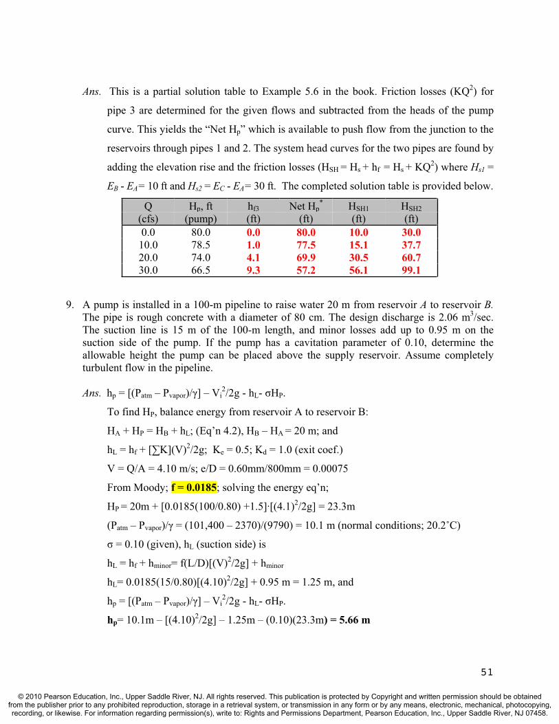
Ans. This is a partial solution table to Example 5.6 in the book. Friction losses (KQ2) for
pipe 3 are determined for the given flows and subtracted from the heads of the pump
curve. This yields the “Net Hp” which is available to push flow from the junction to the
reservoirs through pipes 1 and 2. The system head curves for the two pipes are found by
adding the elevation rise and the friction losses (HSH = Hs + hf = Hs + KQ2) where Hs1 =
EB - EA= 10 ft and Hs2 = EC - EA= 30 ft. The completed solution table is provided below.
Q Hp, ft hf3 Net Hp* HSH1 HSH2
(cfs) (pump) (ft) (ft) (ft) (ft)0.0 80.0 0.0 80.0 10.0 30.0
10.0 78.5 1.0 77.5 15.1 37.720.0 74.0 4.1 69.9 30.5 60.730.0 66.5 9.3 57.2 56.1 99.1
9. A pump is installed in a 100-m pipeline to raise water 20 m from reservoir A to reservoir B. The pipe is rough concrete with a diameter of 80 cm. The design discharge is 2.06 m3/sec.The suction line is 15 m of the 100-m length, and minor losses add up to 0.95 m on the suction side of the pump. If the pump has a cavitation parameter of 0.10, determine the allowable height the pump can be placed above the supply reservoir. Assume completely turbulent flow in the pipeline.
Ans. hp = [(Patm – Pvapor)/ ] – Vi2/2g - hL- HP.
To find HP, balance energy from reservoir A to reservoir B:
HA + HP = HB + hL; (Eq’n 4.2), HB – HA = 20 m; and
hL = hf + [ K](V)2/2g; Ke = 0.5; Kd = 1.0 (exit coef.)
V = Q/A = 4.10 m/s; e/D = 0.60mm/800mm = 0.00075
From Moody; f = 0.0185; solving the energy eq’n;
HP = 20m + [0.0185(100/0.80) +1.5]·[(4.1)2/2g] = 23.3m
(Patm – Pvapor)/ = (101,400 – 2370)/(9790) = 10.1 m (normal conditions; 20.2˚C)
= 0.10 (given), hL (suction side) is
hL = hf + hminor= f(L/D)[(V)2/2g] + hminor
hL= 0.0185(15/0.80)[(4.10)2/2g] + 0.95 m = 1.25 m, and
hp = [(Patm – Pvapor)/ ] – Vi2/2g - hL- HP.
hp= 10.1m – [(4.10)2/2g] – 1.25m – (0.10)(23.3m) = 5.66 m
51
© 2010 Pearson Education, Inc., Upper Saddle River, NJ. All rights reserved. This publication is protected by Copyright and written permission should be obtainedfrom the publisher prior to any prohibited reproduction, storage in a retrieval system, or transmission in any form or by any means, electronic, mechanical, photocopying,recording, or likewise. For information regarding permission(s), write to: Rights and Permissions Department, Pearson Education, Inc., Upper Saddle River, NJ 07458.

10. A pump is tested by a manufacturer to establish the NPSH. At the onset of cavitation, the pump is positioned 10.2 ft above the supply reservoir. The suction line is 10 ft long (f =0.014) with a 1-ft diameter. Minor loss coefficients in the suction line add up to 3.5. If the pumping rate is 3000 gpm (gallons per minute), determine the NPSH. Assume the water temperature is 68°F (20°C).
Ans. hp [(Patm – Pvapor)/ ] – [H’s + V2/2g + hL] where hp = 10.2 ft
Q = 3000gpm (1 cfs/449 gpm) = 6.68 cfs; V = Q/A = (6.68 ft3/s)/[ (0.5ft)2] = 8.51 ft/s
Patm= 14.7 psi = 2117 lbs/ft2; Pvapor= 0.344 psi = 49.5 lbs/ft2
(Patm – Pvapor)/ = (2117 – 49.5)/(62.3) = 33.2 ft, from book jacket. hL (suction side) is
hL = [f(L/D) + K]·[(V)2/2g] = [0.014(10/1) + 3.5]·[(8.51)2/2g] = 4.09 ft, and
hp [(Patm – Pvapor)/ ] – [H’s + V2/2g + hL];
10.2 ft [33.2 ft] – [H’s + (8.51)2/2g + 4.09 ft]; H’s = 17.8 ft
11. Two geometrically-similar, centrifugal pumps are operated at the same efficiency. Pump A operates at 450 rpm, and delivers 2.4 m3/sec against a 22-m head. The scale model (pump B)is one fourth the size with corresponding dimensions and operates at four times the speed. What is the discharge of pump B when it is delivering water against the same head? If the efficiency of pump A is 0.80, determine the power input required of pump B.
Ans. Ns(A) = [ (Q)1/2]/(Hp)3/4 = [(450)(2.4)1/2]/(22)3/4 = 68.6; for pump B
Ns(B) = 68.6 = [1800(Q)1/2]/(22)3/4; Q = 0.150 m3/sec
Pi(A) = QHp/e = [(9790 N/m3)(2.4 m3/sec)(22 m)]/(0.80) = 646 kW
Pi(B) = QHp/e = [(9790 N/m3)(0.150 m3/sec)(22 m)]/(0.80) = 40.4 kW
Alternatively, with the power input for pump A, the specific speed (power) could be
determined and used for pump B to obtain its power input.
12. Select the pump speed with the highest efficiency from the Pump I chart (Figure 5.24 in your book) based on the following conditions. A 1500 m-long (15-cm diameter) pipeline connects two reservoirs with an elevation difference of 35 m. Minor losses include entrance, exit, and a globe valve (assume f = 0.02). Determine the discharge, head, and efficiency for the pump.
Ans. HSH = Hs + hL; where hL = hf + [ K](V)2/2g; and Ke = 0.5, Kv = 10.0, and Kd = 1.0.
Table 3.4, Q = KQ2; K = (0.0826·f·L)/(D5) = (0.0826·0.02·1500)/[(0.15)5] = 32,600
Thus, HSH = Hs + hf + [ K](V)2/2g = 35m + 32,600Q2 + (11.5)V2/2g:
Using this equation, plug in a range of Q values, determine HSH, and superimpose these
points on the pump characteristic curve. This will yield the following:
52
© 2010 Pearson Education, Inc., Upper Saddle River, NJ. All rights reserved. This publication is protected by Copyright and written permission should be obtainedfrom the publisher prior to any prohibited reproduction, storage in a retrieval system, or transmission in any form or by any means, electronic, mechanical, photocopying,recording, or likewise. For information regarding permission(s), write to: Rights and Permissions Department, Pearson Education, Inc., Upper Saddle River, NJ 07458.
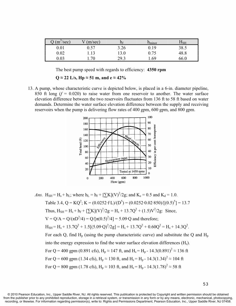
Q (m3/sec) V (m/sec) hf hminor HSH
0.01 0.57 3.26 0.19 38.50.02 1.13 13.0 0.75 48.80.03 1.70 29.3 1.69 66.0
The best pump speed with regards to efficiency: 4350 rpm
Q 22 L/s, Hp 51 m, and e 42%
13. A pump, whose characteristic curve is depicted below, is placed in a 6-in. diameter pipeline, 850 ft long (f = 0.020) to raise water from one reservoir to another. The water surface elevation difference between the two reservoirs fluctuates from 136 ft to 58 ft based on water demands. Determine the water surface elevation difference between the supply and receiving reservoirs when the pump is delivering flow rates of 400 gpm, 600 gpm, and 800 gpm.
53
Ans. HSH = Hs + hL; where hL = hf + [ K](V)2/2g; and Ke = 0.5 and Kd = 1.0.
Table 3.4, Q = KQ2; K = (0.0252·f·L)/(D5) = (0.0252·0.02·850)/[(0.5)5] = 13.7
Thus, HSH = Hs + hf + [ K](V)2/2g = Hs + 13.7Q2 + (1.5)V2/2g: Since,
V = Q/A = Q/( D2/4) = Q/[ (0.5)2/4] = 5.09·Q and therefore;
HSH = Hs + 13.7Q2 + 1.5[(5.09·Q)2/2g] = Hs + 13.7Q2 + 0.60Q2 = Hs + 14.3Q2.
For each Q, find Hp (using the pump characteristic curve) and substitute the Q and Hp
into the energy expression to find the water surface elevation differences (Hs).
For Q = 400 gpm (0.891 cfs), Hp 147 ft, and Hs = Hp - 14.3(0.891)2 136 ft
For Q = 600 gpm (1.34 cfs), Hp 130 ft, and Hs = Hp - 14.3(1.34)2 104 ft
For Q = 800 gpm (1.78 cfs), Hp 103 ft, and Hs = Hp - 14.3(1.78)2 58 ft
© 2010 Pearson Education, Inc., Upper Saddle River, NJ. All rights reserved. This publication is protected by Copyright and written permission should be obtainedfrom the publisher prior to any prohibited reproduction, storage in a retrieval system, or transmission in any form or by any means, electronic, mechanical, photocopying,recording, or likewise. For information regarding permission(s), write to: Rights and Permissions Department, Pearson Education, Inc., Upper Saddle River, NJ 07458.

TEST QUESTIONS & PROBLEMS - CHAPTER #6
Short Answer Questions
1. The flow of water in a small stream during a rainfall even can be described as:a) steady and uniform b) steady and rapidly varied c) steady and gradually varied d) unsteady and uniform e) unsteady and rapidly varied f) unsteady and gradually variedAns. (f) Flood waves are not considered rapidly varied flow phenomenon.
2. What is the difference between steady and uniform flow? Ans. In uniform flow, the discharge and depth of flow remain constant over distance. However, in steady flow, the discharge and depth of flow remain constant over time.
3. (T or F) In gradually varied flow, the channel bottom, water surface, and EGL are parallel.Ans. False This condition is true only in uniform flow.
4. What is the difference between normal depth and uniform depth? Ans. There is no difference.
5. The flow of water in a prismatic irrigation canal during dry weather can be described as:a) steady and uniform b) steady and rapidly varied c) steady and gradually varied e) unsteady and uniform e) unsteady and rapidly varied f) unsteady and gradually variedAns. (a) Most irrigation canals are prismatic and steady, uniform flow is common.
6. (T or F) Manning’s equation is derived from an energy balance. Ans. False It is derived from a force balance. .
7. What type of flow regime is appropriate for the application of Manning’s equation? Ans. Uniform flow.
8. The derivation of Manning’s equation is based upon:a) Newton’s 2nd Law b) impulse-momentum principles c) Bernoulli principle d) continuity principle e) Darcy-Wesibach Ans. (a) Newton’s 2nd Law, with no acceleration, and thus reduces to a force balance..
9. Sketch a profile view of uniform open channel flow and label the bottom, HGL, and EGL. Also label the three major components of energy.
Ans. See Figure 6.1 in the textbook.
54
© 2010 Pearson Education, Inc., Upper Saddle River, NJ. All rights reserved. This publication is protected by Copyright and written permission should be obtainedfrom the publisher prior to any prohibited reproduction, storage in a retrieval system, or transmission in any form or by any means, electronic, mechanical, photocopying,recording, or likewise. For information regarding permission(s), write to: Rights and Permissions Department, Pearson Education, Inc., Upper Saddle River, NJ 07458.

10. What is the definition of wetted perimeter in open channel flow terminology? Ans. It is the contact length of the water and the channel at a cross section.
11. What is the definition of hydraulic radius in open channel flow terminology? Ans. It is the flow area divided by the wetted perimeter, Rh = A/P
12. What are the three forces that are considered in the force balance on a control volume that leads to the development of Manning’s equation for uniform flow? Ans. Hydrostatic pressure forces, the weight of the water body in the reach, and the
resistance force exerted by the channel (bottom and sides) on the flow.
13. Which force term leads to the introduction of hydraulic radius in Manning’s equation? a) hydrostatic pressure b) the weight of the water c) impulse-momentum d) the resistance force exerted by the channel on the flow Ans. (d)
14. Derive the relationship between depth of flow and width for a rectangular channel that is the most hydraulically efficient (i.e., best hydraulic section). Show all steps.Ans. P = b + 2y = A/y + 2y (since A = by; taking the first derivative of P with respect to y:
dP/dy = -A/y2 + 2 = 0; A/y2 = 2; or (b·y)/y2 = 2; b = 2y
15. If a semicircle represents the best hydraulic section, give two reasons why this shape isn’t used for constructed water conveyance channels.Ans. Excavation is difficult, forming is expensive, and bank stability is a problem.
16. What is the width to depth relationship for the best rectangular hydraulic section?Ans. b = 2y
17. (T or F) In constructed channels, the vertical distance from the designed water surface to the top of the channel banks is known as the freeboard of the channel. Ans. True.
18. In the derivation of critical depth, the equation (Q2T)/(gA3) = 1 became V2/(gD) = 1. Show the steps that led to the final equation and define T and D.Ans. Note that Q/A = V and hydraulic depth, D = A/T, where T is the top width. Substituting
these into the first equation and simplifying leads to the second equation.
19. A Froude number of 0.8 indicates:a) subcritical flow b) critical depth c) same as “e” d) normal depth e) there is no “e” f) supercritical flow g) none of the above h) “a” and “d”Ans. (a)
20. (T or F) Normal depth is the depth of flow when the specific energy is at a minimum. Ans. False, critical depth is the minimum energy depth..
55
© 2010 Pearson Education, Inc., Upper Saddle River, NJ. All rights reserved. This publication is protected by Copyright and written permission should be obtainedfrom the publisher prior to any prohibited reproduction, storage in a retrieval system, or transmission in any form or by any means, electronic, mechanical, photocopying,recording, or likewise. For information regarding permission(s), write to: Rights and Permissions Department, Pearson Education, Inc., Upper Saddle River, NJ 07458.

21. Starting with the specific energy equation for open channel flow, E = V2/2g + y, show that you will arrive at (Q2T)/(gA3) = 1 for critical depth (i.e., for minimum energy). Show and explain all steps in the derivation.Ans. E = V2/2g + y = Q2/(2gA2) + d; by substituting V = Q/A = V. To minimize energy with
respect to depth, take the first derivative of this expression and set it equal to zero. dE/dy = -(Q2/gA3)dA/dy + 1 = 0, since dA/dy = T; Q2T/gA3 = 1
22. Which statement below is incorrect? (a) In a given channel the flow depth is higher than the critical depth for the same discharge
when the flow is subcritical (b) In a given channel the specific energy for a given discharge is always higher for
supercritical flow than for subcritical flow. (c) The critical depth in a channel for a given discharge does not depend on the longitudinal
bottom slope of the channel (d) None of the above Ans. (b), examine the specific energy curve to see the fallacy of this.
23. Draw a specific energy curve for a given flow rate, label axes, identify critical depth, subcritical flow, and supercritical flow.Ans. The critical depth is labeled as yc in the graph below, subcritical flow occurs above that
depth and supercritical flow occurs below that depth for the Q specified.
Depth, y
Specific energy, E supercritical
subcriticalyc
24. Which of the following statements is not true when describing the Froude number? a) The Froude number is the ratio of the mean flow velocity to the speed of a surface wave. b) The Froude number is derived from the specific energy equation. c) The Froude number is used to determine normal depth. d) If Nf < 1, flow is subcritical, and if Nf > 1, flow supercritical.e) The concept of top width is introduced in the derivation of the Froude number. Ans. (c) Manning’s equation is used to determine normal depth.
25. Write out the equation for the Froude number. What is it a ratio of and what is it used for? Ans. Nf = V2/gy = V/(gy)1/2. It is the ratio between the mean flow velocity, V, and the speed
of a small gravity (surface) wave traveling over the water surface. It is used to distinguish between subcritical (Nf < 1) and supercritical (Nf > 1) flow.
26. (T or F) The difference between energy and specific energy in open channel flow is that the specific energy uses the channel bottom as a datum (reference). Ans. True.
27. Derive the equation for critical depth in a rectangular channel starting with the Froude number and setting it equal to unity: Nf = V2/gy = 1.
56
© 2010 Pearson Education, Inc., Upper Saddle River, NJ. All rights reserved. This publication is protected by Copyright and written permission should be obtainedfrom the publisher prior to any prohibited reproduction, storage in a retrieval system, or transmission in any form or by any means, electronic, mechanical, photocopying,recording, or likewise. For information regarding permission(s), write to: Rights and Permissions Department, Pearson Education, Inc., Upper Saddle River, NJ 07458.
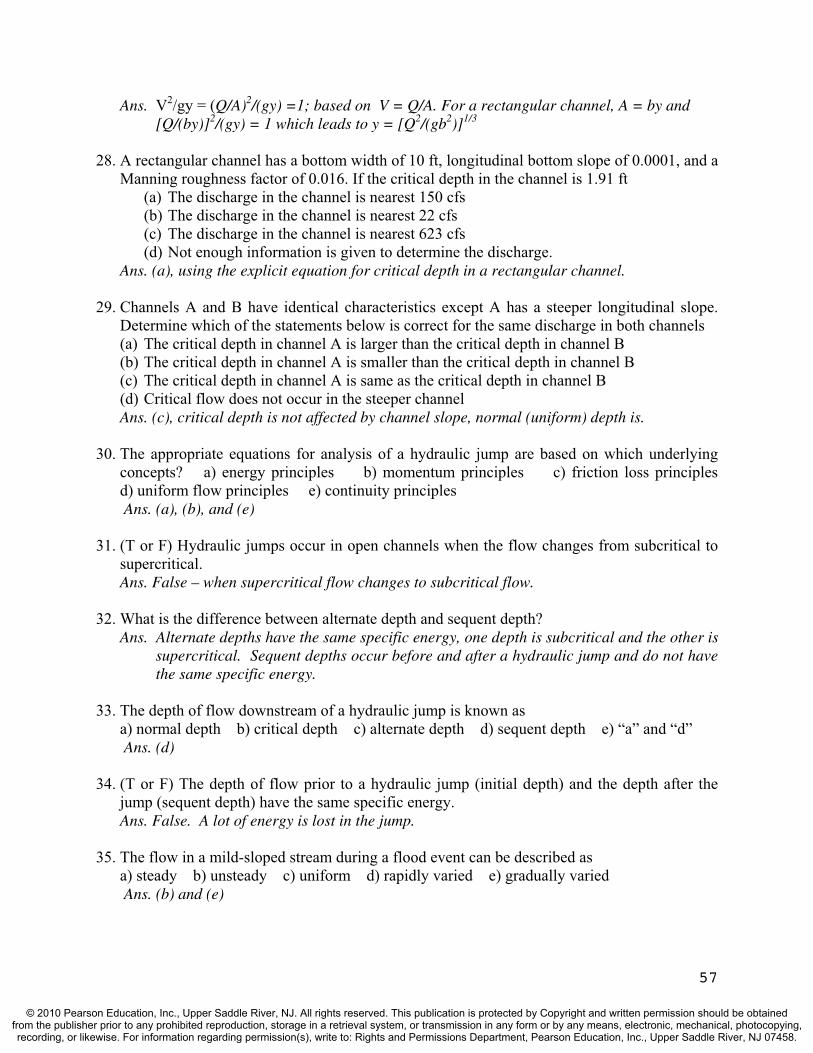
Ans. V2/gy = (Q/A)2/(gy) =1; based on V = Q/A. For a rectangular channel, A = by and [Q/(by)]2/(gy) = 1 which leads to y = [Q2/(gb2)]1/3
28. A rectangular channel has a bottom width of 10 ft, longitudinal bottom slope of 0.0001, and a Manning roughness factor of 0.016. If the critical depth in the channel is 1.91 ft
(a) The discharge in the channel is nearest 150 cfs (b) The discharge in the channel is nearest 22 cfs (c) The discharge in the channel is nearest 623 cfs (d) Not enough information is given to determine the discharge.
Ans. (a), using the explicit equation for critical depth in a rectangular channel.
29. Channels A and B have identical characteristics except A has a steeper longitudinal slope. Determine which of the statements below is correct for the same discharge in both channels (a) The critical depth in channel A is larger than the critical depth in channel B (b) The critical depth in channel A is smaller than the critical depth in channel B (c) The critical depth in channel A is same as the critical depth in channel B (d) Critical flow does not occur in the steeper channel Ans. (c), critical depth is not affected by channel slope, normal (uniform) depth is.
30. The appropriate equations for analysis of a hydraulic jump are based on which underlying concepts? a) energy principles b) momentum principles c) friction loss principles d) uniform flow principles e) continuity principlesAns. (a), (b), and (e)
31. (T or F) Hydraulic jumps occur in open channels when the flow changes from subcritical to supercritical.Ans. False – when supercritical flow changes to subcritical flow.
32. What is the difference between alternate depth and sequent depth? Ans. Alternate depths have the same specific energy, one depth is subcritical and the other is
supercritical. Sequent depths occur before and after a hydraulic jump and do not have the same specific energy.
33. The depth of flow downstream of a hydraulic jump is known as a) normal depth b) critical depth c) alternate depth d) sequent depth e) “a” and “d”
Ans. (d)
34. (T or F) The depth of flow prior to a hydraulic jump (initial depth) and the depth after the jump (sequent depth) have the same specific energy. Ans. False. A lot of energy is lost in the jump.
35. The flow in a mild-sloped stream during a flood event can be described as a) steady b) unsteady c) uniform d) rapidly varied e) gradually varied
Ans. (b) and (e)
57
© 2010 Pearson Education, Inc., Upper Saddle River, NJ. All rights reserved. This publication is protected by Copyright and written permission should be obtainedfrom the publisher prior to any prohibited reproduction, storage in a retrieval system, or transmission in any form or by any means, electronic, mechanical, photocopying,recording, or likewise. For information regarding permission(s), write to: Rights and Permissions Department, Pearson Education, Inc., Upper Saddle River, NJ 07458.

36. What is the relationship between critical depth and normal depth in channels that are classified as steep. Ans. Critical depth is greater than normal depth in steep channels.
37. (T or F) In gradually varied flow, the channel bottom, HGL, and EGL are all parallel. Ans. False, this is only true in uniform flow.
38. What type of gradually varied flow profile would you expect upstream of a dam that is located on a mountain stream?
a) S-1 b) M-1 c) S-2 d) M-2 e) S-3 f) M-3Ans. (a), S because the slope is steep and 1 because the water will be raised considerably.
39. The figure to the left has a (M, C, or S) channel classification and a (1, 2, or 3) flow classification. The figure to the right is a (M, C, or S) channel and a (1, 2, or 3) flow.
Ans. To the left: M-1 and to the right: S-2.
40. Which of the following descriptors are appropriate in describing the flow phenomenon of a flood wave moving down the Mississippi River or the Nile River?
a) steady b) unsteady c) uniform d) rapidly varied e) gradually variedAns. (b) and (e)
41. A trapezoidal channel carrying 300 cfs has a bottom width of 12 ft, side slope of 2 and a longitudinal bottom slope of 0.02. The critical depth is 2.34 ft and the normal depth is 1.25. If the flow depth at a given section is 3.5 ft, the flow profile in the channel is of type (a) M-2 (b) S-1 (c) S-2 (d) None of the above Ans. (b), the channel is steep because yn < yc and flow is S-1 because y is higher than both.
42. What type of gradually varied flow profile do we have if yn < y < yc? If y > yn < yc?Ans. S-2 and M-1
43. (T or F) A control section in an open channel is a location where the relationship between depth and discharge is known.Ans. True.
44. A rectangular channel carrying 200 cfs has a bottom width of 12 ft and a longitudinal bottom slope of 0.001. It has a critical depth of 2.32 ft and a normal depth of 4.0. If the flow depth at a given section is 3.5 ft determine which statement below is incorrect
(a) The flow profile is of type M-2 (b) The flow depth increases in the flow direction (c) The depth decreases in the flow direction (d) The Froude number is less than one.
Ans. (b), in an M-2 profile, the depth decreases in the direction of flow.
58
© 2010 Pearson Education, Inc., Upper Saddle River, NJ. All rights reserved. This publication is protected by Copyright and written permission should be obtainedfrom the publisher prior to any prohibited reproduction, storage in a retrieval system, or transmission in any form or by any means, electronic, mechanical, photocopying,recording, or likewise. For information regarding permission(s), write to: Rights and Permissions Department, Pearson Education, Inc., Upper Saddle River, NJ 07458.

45. What is the principle upon which water surface profiles are determined? Ans. Energy balance.
46. Which principle is not used in the solution of water surface profile computations? a) mass balance b) energy balance c) momentum balance d) Manning’s equation
Ans. (c)
47. A trapezoidal channel carrying 280 cfs has a bottom width of 12 ft, side slope of 2 and a longitudinal bottom slope of 0.001. The critical depth is 2.25 ft and the normal depth is 2.78. The flow depth at the downstream end of this channel is 3.12 ft. Determine which of the statements below is correct
(a) A flow depth of 2.55 ft will not occur in this channel. (b) The flow depth decreases in the flow direction. (c) If the channel is very long, a hydraulic jump will occur. (d) None of the above
Ans. (a), it is an M-1 profile and will reach normal depth (2.78 ft) but not 2.55 ft.
48. A very long trapezoidal channel has a bottom width of 18 ft, side slope of 2, longitudinal bottom slope of 0.01, Manning roughness factor of 0.020, and it carries 800 cfs. The normal depth is 9.25 ft and the critical depth is 3.45 ft. The flow depth at a section along this channel is 3.70 ft. The flow depth 10 ft upstream is most likely to be
(a) 3.79 ft (b) 3.61 ft (c) 5.20 ft (d) 3.45 ft Ans. (a), it is an M-2 profile and the depth will increase as you move upstream.
49. What must be true for a channel to be classified as a critical channel ? Ans. yn = yc
50. What type of gradually varied flow profile is likely to occur when water flows from a reservoir into a spillway?
a) S-1 b) M-1 c) S-2 d) M-2 e) S-3 f) M-3Ans. (c)
51. (T or F) Open channels are generally designed for uniform flow conditions. Ans. True.
52. Give three examples of flexible channel liners.Ans. Grass, riprap, gabions, and grass.
53. Give three examples of rigid channel liners. Ans. Concrete, asphaltic concrete, soil cement, and grouted riprap.
59
© 2010 Pearson Education, Inc., Upper Saddle River, NJ. All rights reserved. This publication is protected by Copyright and written permission should be obtainedfrom the publisher prior to any prohibited reproduction, storage in a retrieval system, or transmission in any form or by any means, electronic, mechanical, photocopying,recording, or likewise. For information regarding permission(s), write to: Rights and Permissions Department, Pearson Education, Inc., Upper Saddle River, NJ 07458.

Problems
1. A trapezoidal open channel has a bottom width of 30 ft and side slopes of 2:1 (H:V). The channel is paved with a concrete surface. If the channel is laid on a slope of 0.0001 and carries a uniform flow at a depth of 6 ft, determine the discharge.
Ans. The flow area is: A = (b + my)y = [30 + (2)(6)](6) = 252 ft2. The wetted perimeter is
P = b + 2y(1 + m2)1/2 = 30 + 2(6)(1 + 22)1/2 = 56.8 ft. Then, the hydraulic radius is
Rh = A/P = (252 ft2)/(56.8 ft) = 4.44 ft. Substituting into Manning’s equation:
Q = (1.49/n)(A)(Rh)2/3(S)1/2 = (1.49/0.013)(252)(4.44)2/3(0.0001)1/2 = 781 cfs
2. A rectangular, irrigation channel with slope 0.0004 needs to be extended and cut through a short section of rock outcropping (n = 0.035). If the width needs to be twice the depth, determine its dimensions for a discharge of 50 m3/sec.
Ans. The flow area is: A = by = 2y2 (with b = 2y); the wetted perimeter is: P = b + 2y = 4y;
and the hydraulic radius is: Rh = A/P = (2y2)/(4y) = y/2. Now using Manning’s eq’n:
Q =(1/n)(A)(Rh)2/3(S)1/2; 50 =(1/0.035)(2y2)(y/2)2/3(0.0004)1/2; y = 4.90 m, b = 9.80 m
3. A concrete channel with an unusual cross section (shown below) carries water at a flow rate of 30 m3/sec. Determine the channel’s slope and flow regime (subcritical or supercritical).
4.0 m
2.0 m
1.6 m
3.6 m
Ans. The flow area is: A = (4)(3.6) – [1/2(2)(2)] = 12.4 m2. The wetted perimeter is
P = 3.6 + 2 + (8)1/2 + 1.6 = 10.0 m. Then, the hydraulic radius is
Rh = A/P = (12.4 m2)/(10.0 m) = 1.24 m. Substituting into Manning’s equation:
Q = (1/n)(A)(Rh)2/3(S)1/2; 30 m3/sec = (1/0.013)(12.4)(1.24)2/3(S)1/2; S = 0.000742
60
© 2010 Pearson Education, Inc., Upper Saddle River, NJ. All rights reserved. This publication is protected by Copyright and written permission should be obtainedfrom the publisher prior to any prohibited reproduction, storage in a retrieval system, or transmission in any form or by any means, electronic, mechanical, photocopying,recording, or likewise. For information regarding permission(s), write to: Rights and Permissions Department, Pearson Education, Inc., Upper Saddle River, NJ 07458.
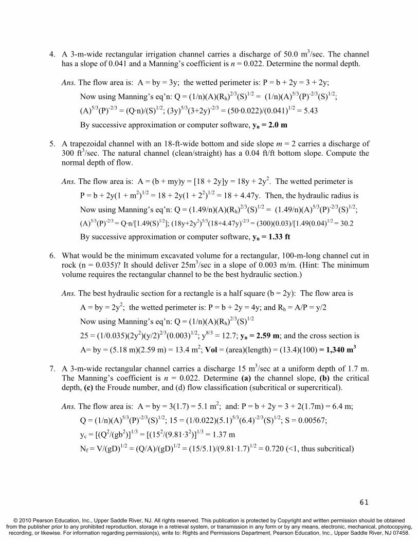
4. A 3-m-wide rectangular irrigation channel carries a discharge of 50.0 m3/sec. The channel has a slope of 0.041 and a Manning’s coefficient is n = 0.022. Determine the normal depth.
Ans. The flow area is: A = by = 3y; the wetted perimeter is: P = b + 2y = 3 + 2y;
Now using Manning’s eq’n: Q = (1/n)(A)(Rh)2/3(S)1/2 = (1/n)(A)5/3(P)-2/3(S)1/2;
(A)5/3(P)-2/3 = (Q·n)/(S)1/2; (3y)5/3(3+2y)-2/3 = (50·0.022)/(0.041)1/2 = 5.43
By successive approximation or computer software, yn = 2.0 m
5. A trapezoidal channel with an 18-ft-wide bottom and side slope m = 2 carries a discharge of 300 ft3/sec. The natural channel (clean/straight) has a 0.04 ft/ft bottom slope. Compute the normal depth of flow.
Ans. The flow area is: A = (b + my)y = [18 + 2y]y = 18y + 2y2. The wetted perimeter is
P = b + 2y(1 + m2)1/2 = 18 + 2y(1 + 22)1/2 = 18 + 4.47y. Then, the hydraulic radius is
Now using Manning’s eq’n: Q = (1.49/n)(A)(Rh)2/3(S)1/2 = (1.49/n)(A)5/3(P)-2/3(S)1/2;
(A)5/3(P)-2/3 = Q·n/[1.49(S)1/2]; (18y+2y2)5/3(18+4.47y)-2/3 = (300)(0.03)/[1.49(0.04)1/2 = 30.2
By successive approximation or computer software, yn = 1.33 ft
6. What would be the minimum excavated volume for a rectangular, 100-m-long channel cut in rock (n = 0.035)? It should deliver 25m3/sec in a slope of 0.003 m/m. (Hint: The minimum volume requires the rectangular channel to be the best hydraulic section.)
Ans. The best hydraulic section for a rectangle is a half square (b = 2y): The flow area is
A = by = 2y2; the wetted perimeter is: P = b + 2y = 4y; and Rh = A/P = y/2
Now using Manning’s eq’n: Q = (1/n)(A)(Rh)2/3(S)1/2
25 = (1/0.035)(2y2)(y/2)2/3(0.003)1/2; y8/3 = 12.7; yn = 2.59 m; and the cross section is
A= by = (5.18 m)(2.59 m) = 13.4 m2; Vol = (area)(length) = (13.4)(100) = 1,340 m3
7. A 3-m-wide rectangular channel carries a discharge 15 m3/sec at a uniform depth of 1.7 m. The Manning’s coefficient is n = 0.022. Determine (a) the channel slope, (b) the critical depth, (c) the Froude number, and (d) flow classification (subcritical or supercritical).
Ans. The flow area is: A = by = 3(1.7) = 5.1 m2; and: P = b + 2y = 3 + 2(1.7m) = 6.4 m;
Q = (1/n)(A)5/3(P)-2/3(S)1/2; 15 = (1/0.022)(5.1)5/3(6.4)-2/3(S)1/2; S = 0.00567;
yc = [(Q2/(gb2)]1/3 = [(152/(9.81·32)]1/3 = 1.37 m
Nf = V/(gD)1/2 = (Q/A)/(gD)1/2 = (15/5.1)/(9.81·1.7)1/2 = 0.720 (<1, thus subcritical)
61
© 2010 Pearson Education, Inc., Upper Saddle River, NJ. All rights reserved. This publication is protected by Copyright and written permission should be obtainedfrom the publisher prior to any prohibited reproduction, storage in a retrieval system, or transmission in any form or by any means, electronic, mechanical, photocopying,recording, or likewise. For information regarding permission(s), write to: Rights and Permissions Department, Pearson Education, Inc., Upper Saddle River, NJ 07458.
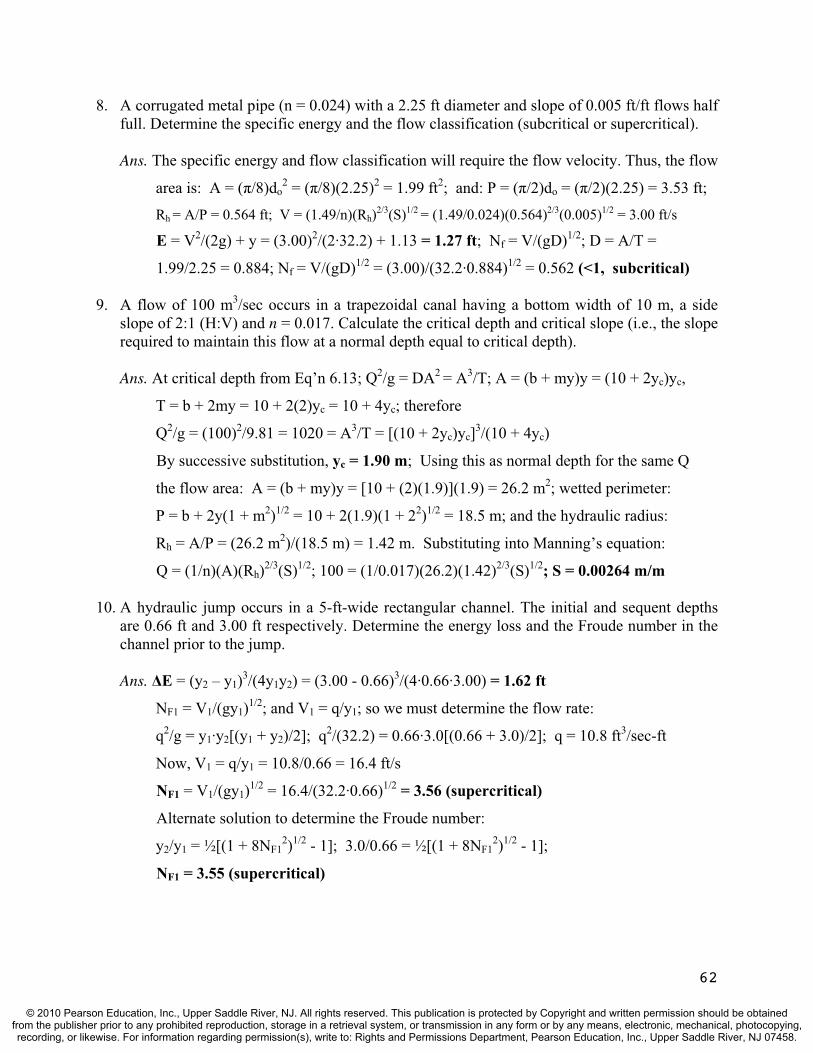
8. A corrugated metal pipe (n = 0.024) with a 2.25 ft diameter and slope of 0.005 ft/ft flows half full. Determine the specific energy and the flow classification (subcritical or supercritical).
Ans. The specific energy and flow classification will require the flow velocity. Thus, the flow
area is: A = ( /8)do2 = ( /8)(2.25)2 = 1.99 ft2; and: P = ( /2)do = ( /2)(2.25) = 3.53 ft;
Rh = A/P = 0.564 ft; V = (1.49/n)(Rh)2/3(S)1/2 = (1.49/0.024)(0.564)2/3(0.005)1/2 = 3.00 ft/s
E = V2/(2g) + y = (3.00)2/(2·32.2) + 1.13 = 1.27 ft; Nf = V/(gD)1/2; D = A/T =
1.99/2.25 = 0.884; Nf = V/(gD)1/2 = (3.00)/(32.2·0.884)1/2 = 0.562 (<1, subcritical)
9. A flow of 100 m3/sec occurs in a trapezoidal canal having a bottom width of 10 m, a side slope of 2:1 (H:V) and n = 0.017. Calculate the critical depth and critical slope (i.e., the slope required to maintain this flow at a normal depth equal to critical depth).
Ans. At critical depth from Eq’n 6.13; Q2/g = DA2 = A3/T; A = (b + my)y = (10 + 2yc)yc,
T = b + 2my = 10 + 2(2)yc = 10 + 4yc; therefore
Q2/g = (100)2/9.81 = 1020 = A3/T = [(10 + 2yc)yc]3/(10 + 4yc)
By successive substitution, yc = 1.90 m; Using this as normal depth for the same Q
the flow area: A = (b + my)y = [10 + (2)(1.9)](1.9) = 26.2 m2; wetted perimeter:
P = b + 2y(1 + m2)1/2 = 10 + 2(1.9)(1 + 22)1/2 = 18.5 m; and the hydraulic radius:
Rh = A/P = (26.2 m2)/(18.5 m) = 1.42 m. Substituting into Manning’s equation:
Q = (1/n)(A)(Rh)2/3(S)1/2; 100 = (1/0.017)(26.2)(1.42)2/3(S)1/2; S = 0.00264 m/m
10. A hydraulic jump occurs in a 5-ft-wide rectangular channel. The initial and sequent depths are 0.66 ft and 3.00 ft respectively. Determine the energy loss and the Froude number in the channel prior to the jump.
Ans. E = (y2 – y1)3/(4y1y2) = (3.00 - 0.66)3/(4·0.66·3.00) = 1.62 ft
NF1 = V1/(gy1)1/2; and V1 = q/y1; so we must determine the flow rate:
q2/g = y1·y2[(y1 + y2)/2]; q2/(32.2) = 0.66·3.0[(0.66 + 3.0)/2]; q = 10.8 ft3/sec-ft
Now, V1 = q/y1 = 10.8/0.66 = 16.4 ft/s
NF1 = V1/(gy1)1/2 = 16.4/(32.2·0.66)1/2 = 3.56 (supercritical)
Alternate solution to determine the Froude number:
y2/y1 = ½[(1 + 8NF12)1/2 - 1]; 3.0/0.66 = ½[(1 + 8NF1
2)1/2 - 1];
NF1 = 3.55 (supercritical)
62
© 2010 Pearson Education, Inc., Upper Saddle River, NJ. All rights reserved. This publication is protected by Copyright and written permission should be obtainedfrom the publisher prior to any prohibited reproduction, storage in a retrieval system, or transmission in any form or by any means, electronic, mechanical, photocopying,recording, or likewise. For information regarding permission(s), write to: Rights and Permissions Department, Pearson Education, Inc., Upper Saddle River, NJ 07458.

11. A hydraulic jump occurs in a 15-m-wide rectangular, concrete channel. The initial (normal) depth comes from a spillway discharge of 100 m3/sec with a slope of 10%. The sequent depth is 3.00 m. Determine the energy loss and the specific force per unit width of channel.
Ans. Prior to the jump: A = by1 = 15y1; and P = 15 + 2y1. Since the initial depth is normal,
use Manning’s eq’n: Q = (1/n)(A)(Rh)2/3(S)1/2 = (1/n)(A)5/3(P)-2/3(S)1/2;
(A)5/3(P)-2/3 = (Q·n)/(S)1/2; (15y1)5/3(15+2y1)-2/3 = (100·0.013)/(0.10)1/2 = 4.11
By successive approximation or computer software, yn = 0.472 m
E = (y2 – y1)3/(4y1y2) = (3.00 - 0.472)3/(4·0.472·3.00) = 2.85 m
Fs = F + qV = ( /2)y12 + (Q/b)V; V = (100/15·0.472) = 14.1 m/sec
Fs = ( /2)y12 + (Q/b)V = (9.79/2)(0.472)2 + (0.998)(100/15)(14.1) = 94.9 kN/m
12. A 5-m-wide, rectangular channel (n = 0.035) flows into a reservoir with a water surface that is 1.93 m above the channel bottom at its end. If the flow rate is 20 m3/sec and the channel slope is 1.9%, determine the channel and flow classification (e.g., M-3, S-2, etc.).
Ans. Determine critical and normal depth: yc = [(Q2/(gb2)]1/3 = [(202/(9.81·52)]1/3 = 1.18 m
For a rectangular channel, A = by = 5y; P = b + 2y = 5 + 2y; from Manning eq’n:
Q·n/(S)1/2 = (A)5/3(P)-2/3; (20)(0.035)/(0.019)1/2 = 5.08 = (5y)5/3(5+2y)-2/3
By successive substitution: yn = 1.18 m. Since yc = yn; channel is critical.
Since y/yc and y/yn are greater than 1.0; flow is Type 1; Classification is C-1
13. Water flows at the rate of 50 m3/sec in a 5-m-wide, rectangular channel (n = 0.011) at a depth of 1.90 m where the bottom elevation is 150 m above MSL. Upstream 100 m, the depth is 2.00 m where the bottom elevation is 151 m above MSL. What is the slope of the energy grade line in this section of channel? Also, determine the channel and flow classification (e.g., M-3, S-2, etc.). (Note: MSL stands for mean sea level, which is the datum.)
Ans. The slope of the energy grade line (EGL) may be found from an energy balance. Thus
V12/2g + y1 + z1 = V2
2/2g + y2 + z2 + L·Se; V1 = Q/A = 5.00 m/s; V2 = 5.26 m/s
(5.00)2/2g + 2.00 + 151 = (5.26)2/2g + 1.90 + 150 + (100)·Se; thus, Se = 0.00964 m/m
Now determine yc and yn: yc = [Q2/(gb2)]1/3 = [502/(9.81·52)]1/3 = 2.17 m
For a rectangular channel, A = by = 5y; P = b + 2y = 5 + 2y; from Manning eq’n:
Q·n/(So)1/2 = (A)5/3(P)-2/3; (50)(0.011)/(0.01)1/2 = 5.50 = (5y)5/3(5+2y)-2/3
By successive substitution: yn = 1.25 m. Since yn < yc; the channel is steep. Since
the water depth is between yc and yn; the flow is Type 2; Classification is S-2
63
© 2010 Pearson Education, Inc., Upper Saddle River, NJ. All rights reserved. This publication is protected by Copyright and written permission should be obtainedfrom the publisher prior to any prohibited reproduction, storage in a retrieval system, or transmission in any form or by any means, electronic, mechanical, photocopying,recording, or likewise. For information regarding permission(s), write to: Rights and Permissions Department, Pearson Education, Inc., Upper Saddle River, NJ 07458.

14. A trapezoidal, concrete channel (n = 0.013) has an 8-ft bottom width and z = 1.0 side slope. It discharges 650 ft3/sec on a 0.001 channel slope. The channel is flowing at normal depth (5.85 ft) when it encounters an obstruction. The obstruction causes the depth to rise to 7.00 ft. If critical depth is 4.80 ft, determine the channel and flow classification (e.g., M-3, S-2, etc.). Also, verify that the depth of flow at a point 100 feet upstream is 6.93 ft by filling in the standard step table shown below.
Section y z A V V2/2g Rh Se Se(avg) L·Se(avg) Total Energy
(ft) (ft) (ft2) (ft/s) (ft) (ft) (ft) (ft)1 7.00 0.000 2 6.93
Ans. Since yn > yc; the channel is mild. Since the water depth is above yc and yn; the flow is
Type 1; Classification is M-1
Section y z A V V2/2g Rh Se Se(avg) L·Se(avg) Total Energy
(ft) (ft) (ft2) (ft/sec) (ft) (ft) (ft) (ft)1 7.00 0.000 105.00 6.190 0.595 3.777 4.96E-04 5.06E-04 0.051 7.646 2 6.93 0.100 103.46 6.282 0.613 3.749 5.16E-04 L = 100 7.643
15. Water flowing at normal depth (2.95 m) in a rectangular concrete channel (n = 0.013) that is 12 m wide encounters an obstruction. The water level rises to 4.55 m to flow over the obstruction. The flow rate is 126 m3/sec and the bottom slope is 0.00086. Determine the channel and flow classification (e.g., M-3, S-2, etc.). Also, verify that the depth of flow at a point 236 m upstream is 4.39 m by filling in the standard step table shown below.
Section y z A V V2/2g Rh Se Se(avg) L·Se(avg) Total Energy
(m) (m) (m2) (m/sec) (m) (m) (m) (m) 1 4.55 10.000 2 4.39
Ans. yc = [Q2/(gb2)]1/3 = [1262/(9.81·122)]1/3 = 2.24 m. Since yn > yc; the channel is mild.
Since the water depth is above yc and yn; the flow is Type 1; Classification is M-1
Section y z A V V2/2g Rh Se Se(avg) L·Se(avg) Total Energy
(m) (m) (m2) (m/sec) (m) (m) (m) (m) 1 4.55 10.000 54.6 2.31 0.271 2.59 2.53E-04 2.67E-04 0.063 14.884 2 4.39 10.203 52.7 2.39 0.292 2.54 2.80E-04 L = 236 14.885
64
© 2010 Pearson Education, Inc., Upper Saddle River, NJ. All rights reserved. This publication is protected by Copyright and written permission should be obtainedfrom the publisher prior to any prohibited reproduction, storage in a retrieval system, or transmission in any form or by any means, electronic, mechanical, photocopying,recording, or likewise. For information regarding permission(s), write to: Rights and Permissions Department, Pearson Education, Inc., Upper Saddle River, NJ 07458.
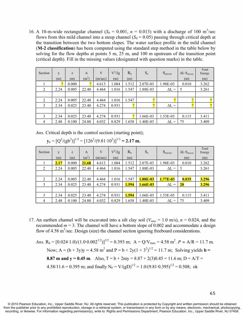
65
16. A 10-m-wide rectangular channel (S0 = 0.001, n = 0.013) with a discharge of 100 m3/secflows from this mild channel into a steep channel (S0 = 0.05) passing through critical depth at the transition between the two bottom slopes. The water surface profile in the mild channel (M-2 classification) has been computed using the standard step method in the table below by solving for the flow depths at points 5 m, 25 m, and 100 m upstream of the transition point (critical depth). Fill in the missing values (designated with question marks) in the table.
Section y z A V V2/2g Rh Se Se(avg) L·Se(avg)
TotalEnergy
(m) (m) (m2) (m/sec) (m) (m) (m) (m) 1 ? 0.000 ? 4.613 1.084 1.512 2.07E-03 1.98E-03 0.010 3.262 2 2.24 0.005 22.40 4.464 1.016 1.547 1.88E-03 L = 5 3.261 2 2.24 0.005 22.40 4.464 1.016 1.547 ? ? ? ?3 2.34 0.025 23.40 4.274 0.931 ? ? L = ? ? 3 2.34 0.025 23.40 4.274 0.931 ? 1.66E-03 1.53E-03 0.115 3.411 4 2.48 0.100 24.80 4.032 0.829 1.658 1.40E-03 L = 75 3.409
Ans. Critical depth is the control section (starting point);
yc = [Q2/(gb2)]1/3 = [1262/(9.81·102)]1/3 = 2.17 m.
Section y z A V V2/2g Rh Se Se(avg) L·Se(avg)
TotalEnergy
(m) (m) (m2) (m/sec) (m) (m) (m) (m) 1 2.17 0.000 21.68 4.613 1.084 1.512 2.07E-03 1.98E-03 0.010 3.262 2 2.24 0.005 22.40 4.464 1.016 1.547 1.88E-03 L = 5 3.261 2 2.24 0.005 22.40 4.464 1.016 1.547 1.88E-03 1.77E-03 0.035 3.296 3 2.34 0.025 23.40 4.274 0.931 1.594 1.66E-03 L = 20 3.296 3 2.34 0.025 23.40 4.274 0.931 1.594 1.66E-03 1.53E-03 0.115 3.411 4 2.48 0.100 24.80 4.032 0.829 1.658 1.40E-03 L = 75 3.409
17. An earthen channel will be excavated into a silt clay soil (Vmax = 1.0 m/s), n = 0.024, and the recommended m = 3. The channel will have a bottom slope of 0.002 and accommodate a design flow of 4.58 m3/sec. Design (size) the channel section ignoring freeboard considerations.
Ans. Rh = [0.024·1.0)/(1.0·0.0021/2)]3/2 = 0.393 m; A = Q/Vmax = 4.58 m2. P = A/R = 11.7 m.
Now; A = (b + 3y)y = 4.58 m2 and P = b + 2y(1 + 32)1/2 = 11.7 m; Solving yields b =
8.87 m and y = 0.45 m. Also, T = b + 2my = 8.87 + 2(3)0.45 = 11.6 m; D = A/T =
4.58/11.6 = 0.395 m; and finally NF = V/(gD)1/2 = 1.0/(9.81·0.395)1/2 = 0.508; ok
© 2010 Pearson Education, Inc., Upper Saddle River, NJ. All rights reserved. This publication is protected by Copyright and written permission should be obtainedfrom the publisher prior to any prohibited reproduction, storage in a retrieval system, or transmission in any form or by any means, electronic, mechanical, photocopying,recording, or likewise. For information regarding permission(s), write to: Rights and Permissions Department, Pearson Education, Inc., Upper Saddle River, NJ 07458.
TEST QUESTIONS & PROBLEMS - CHAPTER #7
Short Answer Questions
1. (T or F) Aquifer permeability is affected by groundwater temperature.Ans. True. It affects the specific weight and viscosity in Equation (7.3).
2. Why is the velocity head component of hydraulic head not considered in Darcy’s equation? Ans. Groundwater moves very slowly, so the velocity head term is generally very small
compared to the position head and the pressure head (for confined flow) terms. Thus, it can be ignored without a loss in accuracy.
3. The three different types of groundwater velocity include all of the following except:a) pore velocity b) apparent velocity c) actual velocity d) seepage velocity Ans. (a) Pore velocity was not a term used in this book.
4. (T or F) The higher the porosity, the easier it is to extract water from an aquifer. Ans. False. Other factors enter in including size and connectivity of the pore spaces.
5. Name the three different types of groundwater velocity and define each.Ans. Apparent - used in Darcy’s equation V = k(dh/dL) or V = Q/A; A = total area
Seepage - average flow speed based on pore area = L/t = V/ ; L = straight distance Actual - based on real (tortuous path) distance traveled by molecules (>Vs).
6. (T or F) The theoretical upper limit of porosity is 100%. Ans. True.
7. Explain the difference between a confined and an unconfined aquifer.Ans. A confined aquifer contains water that is under pressure and has a relatively
impermeable boundary above the saturated layer.
8. Withdrawals from aquifers can result from which of the following mechanisms? a) springs b) wells c) influent streams d) infiltration of rainwater e) transpiration Ans. (a), (b), and (e); the rest contribute water to the aquifer.
9. Define two limitations to laboratory determined permeabilities using core samples. Ans. Representativeness, wall effects, entrained air, sample disturbance, anisotropy.
10. The ratio of volume of voids to total volume in porous media is called:a) void ratio b) specific yield c) water ratio d) porosityAns. (d) porosity.
11. (T or F) In general, the porosity of gravel is higher than that of clay.Ans. False. See Table 7.1.
66
© 2010 Pearson Education, Inc., Upper Saddle River, NJ. All rights reserved. This publication is protected by Copyright and written permission should be obtainedfrom the publisher prior to any prohibited reproduction, storage in a retrieval system, or transmission in any form or by any means, electronic, mechanical, photocopying,recording, or likewise. For information regarding permission(s), write to: Rights and Permissions Department, Pearson Education, Inc., Upper Saddle River, NJ 07458.
12. What is the difference between seepage velocity and actual velocity? Ans. Seepage velocity relates to average straight line velocity between two locations, or the
average flow based on pore area; Vs = L/t = V/ ; L = straight distance Actual velocity is based on real (tortuous path) distance traveled by molecules (>Vs).
.13. Show all steps in the proof of the well equation for unconfined aquifer under state flow
conditions starting with Darcy’s expression: Q = 2 rhK(dh/dr).Ans. (Q/r)dr=2 Kh(dh); Q and K are constant, and integrating both sides yields
Q(ln r) = 2 K(h2/2)+ C; w/boundary conditions (r = rw, h = hw) and (r = ro, h = ho): Q·ln (ro/rw)= K(ho
2 – hw2); thus Q = K· [(ho
2 – hw2)/ ln (ro/rw)].
14. (T or F) A homogeneous aquifer implies the permeability is independent of flow direction.Ans. False. This is a characteristic of an isotropic aquifer.
15. Define the cone of depression in groundwater flow.Ans. In a homogeneous, isotropic aquifer, it is the axisymmetric drawdown curve with a
conic-shaped geometry produced by a pumping well.
16. When the permeability of an aquifer is dependent upon direction, the appropriate term is:a) homogeneous b) heterogeneous c) isotropic d) anisotropic e) don’t know Ans. (d); anisotropic
17. Describe how you would determine the drawdown in a confined aquifer at a location that was impacted by two pumped wells in the vicinity. What principle is being invoked? Ans. Determine the drawdowns separately and add them together, called superposition .
18. A 50 cm3 sand sample is collected from an aquifer. When the sample is oven dried and poured into a graduated cylinder, it displaces 30 ml of water. Determine the porosity. Ans. = Volv/Vol = (50 – 30)/50 = 0.40 (Note: 30 ml = 30 cm3)
19. (T or F) In confined aquifers, the value of the storage coefficient is much lower than in unconfined aquifers.Ans. True. In confined aquifers, the pores do not drain. Water is removed by compression of
the saturated layer and expansion of the ground water.
20. Why is the storage coefficient larger in confined aquifers than in unconfined aquifers? Ans. The storage coefficient in unconfined aquifers may approach the porosity since water is
drained from the pores. However, in confined aquifers the pores do not drain. Water is removed by compression of the saturated layer and expansion of the ground water.
21. Which of the following terms is a dimensionless number defined as the water yield from a column of aquifer (of unit area) that results from lowering the water table or piezometric surface by a unit height. a) porosity b) permeability c) hydraulic conductivity d) transmissibility e) storage coefficient Ans. (e); storage coefficient
67
© 2010 Pearson Education, Inc., Upper Saddle River, NJ. All rights reserved. This publication is protected by Copyright and written permission should be obtainedfrom the publisher prior to any prohibited reproduction, storage in a retrieval system, or transmission in any form or by any means, electronic, mechanical, photocopying,recording, or likewise. For information regarding permission(s), write to: Rights and Permissions Department, Pearson Education, Inc., Upper Saddle River, NJ 07458.
22. Describe the difference between steady and unsteady radial flow in an unconfined aquifer.Ans. For unsteady flow, the radius of influence of the water table has not achieved a steady
state (i.e., the radius of influence continues to expand with time).
23. (T or F) For unsteady radial flow in confined aquifers, the principal of superposition may be used to solve for the drawdown of multiple wells and for unsteady well pumping rates. Ans. True.
24. For unsteady radial flow in confined aquifers, which of the following parameters affect the drawdown at a specific location within the radius of influence? a) time since pumping began b) the radial distance from the well to the point of interest c) transmissibility d) storage coefficient e) the well pumping rate Ans. All of these parameters affect the drawdown
25. Define the term aquifer recovery in unconfined aquifers.Ans. Aquifer recovery is the rise of the water table once pumping of the well has stopped.
26. (T or F) The basic idea (premise) in analyzing field pumping test data to determine an aquifer’s hydraulic characteristics is to fit the observed drawdowns to available analytical solutions.Ans. True.
27. Why are field pumping tests more reliable in determining an aquifer’s hydraulic paramenters than laboratory tests done on aquifer samples. Ans. There are many reasons that lab tests are not reliable, but one of the biggest reasons is
that it is rare to get a sample or samples that is representative of the entire aquifer.
28. (T or F) An aquifer’s storage coefficient can be obtained from a field pumping test under equilibrium (steady aquifer flow) conditions. Ans. False. It requires a non-equilibrium test (unsteady flow in the aquifer).
29. All of the following items are required for an equilibrium test in a confined aquifer except: a) the aquifer storage coefficient b) drawdown measurements in at least two wells c) drawdown measurements taken after aquifer equilibrium is achieved d) radial distances to the wells where drawdowns are being measured Ans. (a) the aquifer storage coefficient is not required
30. All of the following are required for an equilibrium test in an unconfined aquifer except: a) a completely penetrating pumped well b) pump flow equilibrium must be achieved c) drawdown measurements in at least two wells d) radial distances to the observed wellsAns. (b) aquifer flow equilibrium must be achieved, not pump flow equilibrium
31. (T or F) Analytical solutions are not available for unsteady flow in unconfined aquifers to determine the storage coefficient. Ans. True. However, the confined aquifer procedures can be applied to unconfined aquifers if
the drawdowns are very small compared to the thickness of the aquifer.
68
© 2010 Pearson Education, Inc., Upper Saddle River, NJ. All rights reserved. This publication is protected by Copyright and written permission should be obtainedfrom the publisher prior to any prohibited reproduction, storage in a retrieval system, or transmission in any form or by any means, electronic, mechanical, photocopying,recording, or likewise. For information regarding permission(s), write to: Rights and Permissions Department, Pearson Education, Inc., Upper Saddle River, NJ 07458.
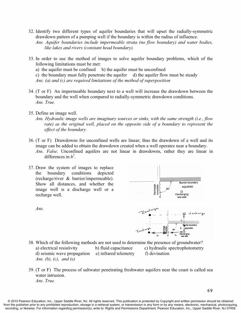
32. Identify two different types of aquifer boundaries that will upset the radially-symmetric drawdown pattern of a pumping well if the boundary is within the radius of influence.Ans. Aquifer boundaries include impermeable strata (no flow boundary) and water bodies,
like lakes and rivers (constant head boundary).
33. In order to use the method of images to solve aquifer boundary problems, which of the following limitations must be met: a) the aquifer must be confined b) the aquifer must be unconfined c) the boundary must fully penetrate the aquifer d) the aquifer flow must be steady Ans. (a) and (c) are required limitations of the method of superposition
34. (T or F) An impermeable boundary next to a well will increase the drawdown between the boundary and the well when compared to radially-symmetric drawdown conditions. Ans. True.
35. Define an image well. Ans. Hydraulic image wells are imaginary sources or sinks, with the same strength (i.e., flow
rate) as the original well, placed on the opposite side of a boundary to represent the effect of the boundary.
36. (T or F) Drawdowns for unconfined wells are linear; thus the drawdown of a well and its image can be added to obtain the drawdown created when a well operates near a boundary. Ans. False. Unconfined aquifers are not linear in drawdowns, rather they are linear in
differences in h2.
37. Draw the system of images to replace the boundary conditions depicted (recharge/river & barrier/impermeable). Show all distances, and whether the image well is a discharge well or a recharge well.
69
Ans.
38. Which of the following methods are not used to determine the presence of groundwater? a) electrical resistivity b) fluid capacitance c) hydraulic spectrophotometry d) seismic wave propagation e) infrared telemetry f) devination Ans. (b), (c), and (e)
39. (T or F) The process of saltwater penetrating freshwater aquifers near the coast is called sea water intrusion. Ans. True.
© 2010 Pearson Education, Inc., Upper Saddle River, NJ. All rights reserved. This publication is protected by Copyright and written permission should be obtainedfrom the publisher prior to any prohibited reproduction, storage in a retrieval system, or transmission in any form or by any means, electronic, mechanical, photocopying,recording, or likewise. For information regarding permission(s), write to: Rights and Permissions Department, Pearson Education, Inc., Upper Saddle River, NJ 07458.
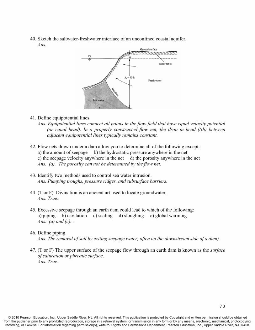
40. Sketch the saltwater-freshwater interface of an unconfined coastal aquifer. Ans.
41. Define equipotential lines. Ans. Equipotential lines connect all points in the flow field that have equal velocity potential
(or equal head). In a properly constructed flow net, the drop in head ( h) between adjacent equipotential lines typically remains constant.
42. Flow nets drawn under a dam allow you to determine all of the following except: a) the amount of seepage b) the hydrostatic pressure anywhere in the net c) the seepage velocity anywhere in the net d) the porosity anywhere in the netAns. (d). The porosity can not be determined by the flow net.
43. Identify two methods used to control sea water intrusion. Ans. Pumping troughs, pressure ridges, and subsurface barriers.
44. (T or F) Divination is an ancient art used to locate groundwater.Ans. True..
45. Excessive seepage through an earth dam could lead to which of the following: a) piping b) cavitation c) scaling d) sloughing e) global warming Ans. (a) and (c). .
46. Define piping.Ans. The removal of soil by exiting seepage water, often on the downstream side of a dam).
47. (T or F) The upper surface of the seepage flow through an earth dam is known as the surface of saturation or phreatic surface.Ans. True..
70
© 2010 Pearson Education, Inc., Upper Saddle River, NJ. All rights reserved. This publication is protected by Copyright and written permission should be obtainedfrom the publisher prior to any prohibited reproduction, storage in a retrieval system, or transmission in any form or by any means, electronic, mechanical, photocopying,recording, or likewise. For information regarding permission(s), write to: Rights and Permissions Department, Pearson Education, Inc., Upper Saddle River, NJ 07458.
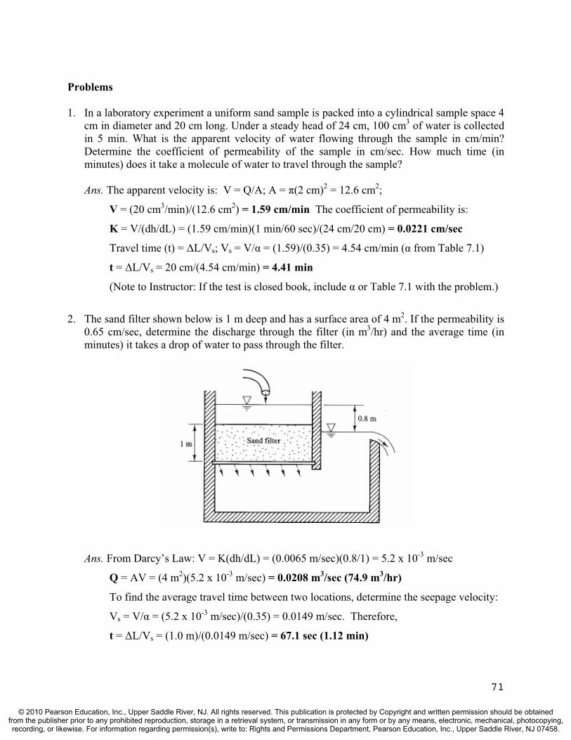
Problems
1. In a laboratory experiment a uniform sand sample is packed into a cylindrical sample space 4 cm in diameter and 20 cm long. Under a steady head of 24 cm, 100 cm3 of water is collected in 5 min. What is the apparent velocity of water flowing through the sample in cm/min? Determine the coefficient of permeability of the sample in cm/sec. How much time (in minutes) does it take a molecule of water to travel through the sample?
Ans. The apparent velocity is: V = Q/A; A = (2 cm)2 = 12.6 cm2;
V = (20 cm3/min)/(12.6 cm2) = 1.59 cm/min The coefficient of permeability is:
K = V/(dh/dL) = (1.59 cm/min)(1 min/60 sec)/(24 cm/20 cm) = 0.0221 cm/sec
Travel time (t) = L/Vs; Vs = V/ = (1.59)/(0.35) = 4.54 cm/min ( from Table 7.1)
t = L/Vs = 20 cm/(4.54 cm/min) = 4.41 min
(Note to Instructor: If the test is closed book, include or Table 7.1 with the problem.)
2. The sand filter shown below is 1 m deep and has a surface area of 4 m2. If the permeability is 0.65 cm/sec, determine the discharge through the filter (in m3/hr) and the average time (in minutes) it takes a drop of water to pass through the filter.
Ans. From Darcy’s Law: V = K(dh/dL) = (0.0065 m/sec)(0.8/1) = 5.2 x 10⁻³ m/sec
Q = AV = (4 m2)(5.2 x 10⁻³ m/sec) = 0.0208 m3/sec (74.9 m3/hr)
To find the average travel time between two locations, determine the seepage velocity:
Vs = V/ = (5.2 x 10⁻³ m/sec)/(0.35) = 0.0149 m/sec. Therefore,
t = L/Vs = (1.0 m)/(0.0149 m/sec) = 67.1 sec (1.12 min)
71
© 2010 Pearson Education, Inc., Upper Saddle River, NJ. All rights reserved. This publication is protected by Copyright and written permission should be obtainedfrom the publisher prior to any prohibited reproduction, storage in a retrieval system, or transmission in any form or by any means, electronic, mechanical, photocopying,recording, or likewise. For information regarding permission(s), write to: Rights and Permissions Department, Pearson Education, Inc., Upper Saddle River, NJ 07458.
3. In a field test, a time of 84 hours was required for a tracer to travel from one observation well to another. The wells are 100 ft apart, and the difference in their water surface elevations is 2 ft. Samples of the aquifer between the wells indicate the porosity is about 35%. Compute the coefficient of permeability (in ft/sec) of the aquifer assuming it is homogeneous.
Ans. Based on the travel time between two locations, we can determine the seepage velocity:
Vs = L/t = (100 ft)/(84 hrs) = 1.19 ft/hr = 28.6 ft/day. Also, the apparent velocity is
V = Vs· = (28.6 ft/day)(0.35) = 10.0 ft/day. Finally, using the Darcy equation,
K = V/(dh/dL) = (10 ft/day)/(2 ft/100 ft) = 500 ft/day = 5.79 x 10⁻³ ft/sec
4. A confined aquifer is pumped by a 30-cm-diameter well at the rate of 4.42 x 10⁻² m3/sec.Steady flow has been achieved, and the radius of influence is 440 m. The field coefficient of permeability has been determined by a previous test in the area to be 2.02 x 10⁻⁴ m/sec. If the drawdown at the well is 11.4 m, determine the thickness of the aquifer.
Ans. Based on Equation (7.6), Q = 2 Kb(ho-hw)/ln(ro/rw) (Note: ho - hw = sw - so = sw):
4.42 x 10⁻² m3/sec = 2 (2.02 x 10⁻⁴ m/sec)(b)(11.4 m)/ln(440/0.15); b = 24.4 m
Alternative solution: Using Eq’n 7.11 with the pumped well as the observation well.
Also note that; T = Kb in the equation. Therefore; s = sob + (Q/2 Kb) ln(rob/r)
0 = 11.4 m + [(4.42 x 10⁻² m3/sec)/(2 b·2.02 x 10-4 m/sec)]ln(0.15/440); b = 24.4 m
5. An observation well is located on an industrial site that contains two discharge wells. The water table depth in the observation well registers 131 feet (an unconfined aquifer where the permeability is K = 6.56 ft/day). Two discharge wells (#1 and #2) exist on the property and are being pumped at the rate of 550 and 91.7 gpm (gal/min), respectively. The observation well is 164 ft from well #1 and 210 ft from well #2. Determine the water table depth at the location of an oil spill which is 65.6 ft from well #1 and 75.4 ft from well #2. Can you make a logical guess as to which well the oil will end up contaminating? Explain your answer.
Ans. Noting that 1 cfs = 449 gpm: Q1 = 550/449 = 1.22 cfs; Q2 = 91.7/449 = 0.204 cfs.
Also, K = 6.56 ft/day = 7.59 x 10⁻⁵ ft/sec. Now applying Eq’n (7.17) yields:
h2 = hob2 – (Q1/ K)ln(r1o/r1) - (Q2/ K)ln(r2o/r2) = 1312 – [1.22/( ·7.59 x 10⁻⁵)]ln(164/65.6)
– [0.204/( ·7.59 x 10⁻⁵)]ln(210/75.4) = 11,600 ft2; h = 108 ft.
Both wells could be contaminated since a positive gradient could exist toward both
wells based on the angle formed between the wells and the spill location. However, the
highest gradient is toward well #1 which is closer and has a greater pumping rate.
72
© 2010 Pearson Education, Inc., Upper Saddle River, NJ. All rights reserved. This publication is protected by Copyright and written permission should be obtainedfrom the publisher prior to any prohibited reproduction, storage in a retrieval system, or transmission in any form or by any means, electronic, mechanical, photocopying,recording, or likewise. For information regarding permission(s), write to: Rights and Permissions Department, Pearson Education, Inc., Upper Saddle River, NJ 07458.

6. A 40-cm-diameter well draws water from a confined aquifer at the rate of 0.101 m3/sec. The aquifer is 30.5 m thick with a piezometric surface (prior to pumping) that is 107 m above the bottom of the confined aquifer. The drawdown at an observation well 50 m away is 10.1 m, and the drawdown at the well is 30.5 m. Determine the radius of influence of the well.
Ans. The aquifer K is not given. Use Eq’n (7.7), with the observation well and the pumped
well data to obtain it. Note that hw = 107 – 30.5 = 76.5 m & h = 107 – 10.1 = 96.9 m
Q = 2 Kb(h-hw)/ln(r/rw); 0.101 m3/sec = 2 K(96.9m – 76.5m)/ln(50/0.20);
K = 4.35 x 10⁻³ m/sec. Now apply Equation (7.6) to obtain the radius of influence.
Q = 2 Kb(ho-hw)/ln(ro/rw); 0.101 = 2 (4.35 x 10⁻³)(30.5)/ln(ro/0.20); ro = 768 m
Alternative solution:
Using Eq’n 7.8 with the observation well data as r and h yields.
h - hw = (ho - hw)[ln(r/rw)/ln(ro/rw)];
96.9 - 76.5 = (30.5)[ln(50/0.2)/ln(ro/0.2)]; ro = 769 m
7. A 16-inch radius well draws water from a confined aquifer at the rate of 3.5 cfs. The confined aquifer is 100 feet thick with a piezometric surface (prior to pumping) that is 350 feet above the bottom of the confined aquifer. The drawdown at an observation well 165 feet away is 33 feet, and the radius of influence is 1780 ft. Determine the drawdown at the well and the coefficient of permeability.
Ans. The aquifer K is not given. Use Eq’n (7.10), with the observation well and the radius of
influence to obtain it. Note that ho = h = 350 ft & hob = 350 – 33 = 317 ft
h = hob + (Q/2 T)ln(r/rob); 350 = 317 + (3.5/2 T)ln(1780/165); T = 0.0401 ft2/sec
and since T = Kb; K = T/b = 0.0401/100 = 4.01 x 10⁻⁴ ft/sec
Now apply Equation (7.6) to obtain the drawdown at the well.
Q = 2 Kb(ho-hw)/ln(ro/rw); 3.5 = 2 (4.01x10⁻⁴)(100)(350-hw)/ln(1780/1.33);
hw = 250 ft ; Therefore, sw = ho - hw = 350 – 250 = 100 ft
Alternative solution:
Using Eq’n 7.8 with the observation well data as r and h yields.
h - hw = (ho - hw)[ln(r/rw)/ln(ro/rw)];
317 - hw = (350 - hw)[ln(165/1.33)/ln(1780/1.33)]; hw = 250 ft; thus sw = 100 ft
Then solve Equation (7.6) to obtain the coefficient of permeability.
73
© 2010 Pearson Education, Inc., Upper Saddle River, NJ. All rights reserved. This publication is protected by Copyright and written permission should be obtainedfrom the publisher prior to any prohibited reproduction, storage in a retrieval system, or transmission in any form or by any means, electronic, mechanical, photocopying,recording, or likewise. For information regarding permission(s), write to: Rights and Permissions Department, Pearson Education, Inc., Upper Saddle River, NJ 07458.
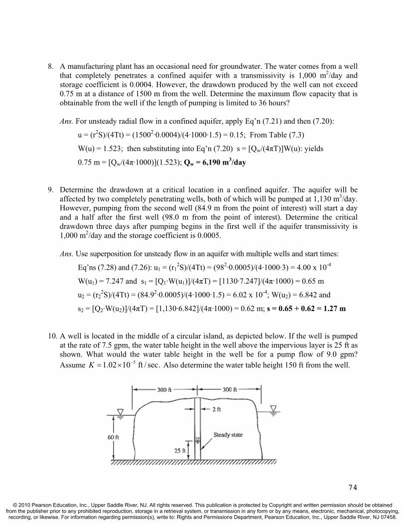
8. A manufacturing plant has an occasional need for groundwater. The water comes from a well that completely penetrates a confined aquifer with a transmissivity is 1,000 m2/day and storage coefficient is 0.0004. However, the drawdown produced by the well can not exceed 0.75 m at a distance of 1500 m from the well. Determine the maximum flow capacity that is obtainable from the well if the length of pumping is limited to 36 hours?
Ans. For unsteady radial flow in a confined aquifer, apply Eq’n (7.21) and then (7.20):
u = (r2S)/(4Tt) = (15002·0.0004)/(4·1000·1.5) = 0.15; From Table (7.3)
W(u) = 1.523; then substituting into Eq’n (7.20) s = [Qw/(4 T)]W(u): yields
0.75 m = [Qw/(4 ·1000)](1.523); Qw = 6,190 m3/day
9. Determine the drawdown at a critical location in a confined aquifer. The aquifer will be affected by two completely penetrating wells, both of which will be pumped at 1,130 m3/day.However, pumping from the second well (84.9 m from the point of interest) will start a day and a half after the first well (98.0 m from the point of interest). Determine the critical drawdown three days after pumping begins in the first well if the aquifer transmissivity is 1,000 m2/day and the storage coefficient is 0.0005.
Ans. Use superposition for unsteady flow in an aquifer with multiple wells and start times:
Eq’ns (7.28) and (7.26): u1 = (r12S)/(4Tt) = (982·0.0005)/(4·1000·3) = 4.00 x 10⁻⁴
W(u1) = 7.247 and s1 = [Q1·W(u1)]/(4 T) = [1130·7.247]/(4 ·1000) = 0.65 m
u2 = (r22S)/(4Tt) = (84.92·0.0005)/(4·1000·1.5) = 6.02 x 10⁻⁴; W(u2) = 6.842 and
s2 = [Q2·W(u2)]/(4 T) = [1,130·6.842]/(4 ·1000) = 0.62 m; s = 0.65 + 0.62 = 1.27 m
10. A well is located in the middle of a circular island, as depicted below. If the well is pumped at the rate of 7.5 gpm, the water table height in the well above the impervious layer is 25 ft as shown. What would the water table height in the well be for a pump flow of 9.0 gpm? Assume Also determine the water table height 150 ft from the well. .sec/ft 1002.1 5K
74
© 2010 Pearson Education, Inc., Upper Saddle River, NJ. All rights reserved. This publication is protected by Copyright and written permission should be obtainedfrom the publisher prior to any prohibited reproduction, storage in a retrieval system, or transmission in any form or by any means, electronic, mechanical, photocopying,recording, or likewise. For information regarding permission(s), write to: Rights and Permissions Department, Pearson Education, Inc., Upper Saddle River, NJ 07458.
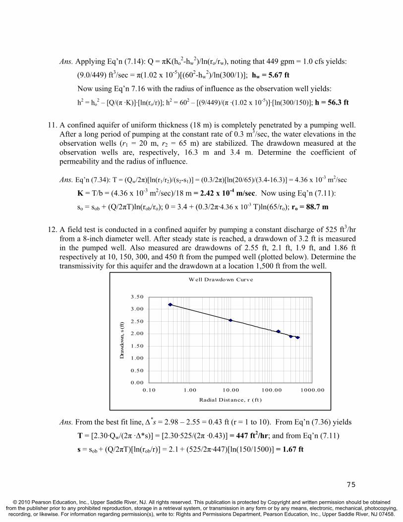
Ans. Applying Eq’n (7.14): Q = K(ho2-hw
2)/ln(ro/rw), noting that 449 gpm = 1.0 cfs yields:
(9.0/449) ft3/sec = (1.02 x 10⁻⁵)[(602-hw2)/ln(300/1)]; hw = 5.67 ft
Now using Eq’n 7.16 with the radius of influence as the observation well yields:
h2 = ho2 – [Q/( ·K)]·[ln(ro/r)]; h2 = 602 – [(9/449)/( ·(1.02 x 10⁻⁵)]·[ln(300/150)]; h = 56.3 ft
11. A confined aquifer of uniform thickness (18 m) is completely penetrated by a pumping well. After a long period of pumping at the constant rate of 0.3 m3/sec, the water elevations in the observation wells (r1 = 20 m, r2 = 65 m) are stabilized. The drawdown measured at the observation wells are, respectively, 16.3 m and 3.4 m. Determine the coefficient of permeability and the radius of influence.
Ans. Eq’n (7.34): T = (Qw/2 )[ln(r1/r2)/(s2-s1)] = (0.3/2 )[ln(20/65)/(3.4-16.3)] = 4.36 x 10⁻³ m2/sec
K = T/b = (4.36 x 10⁻³ m2/sec)/18 m = 2.42 x 10⁻⁴ m/sec. Now using Eq’n (7.11):
so = sob + (Q/2 T)ln(rob/ro); 0 = 3.4 + (0.3/2 ·4.36 x 10-3 T)ln(65/ro); ro = 88.7 m
12. A field test is conducted in a confined aquifer by pumping a constant discharge of 525 ft3/hrfrom a 8-inch diameter well. After steady state is reached, a drawdown of 3.2 ft is measured in the pumped well. Also measured are drawdowns of 2.55 ft, 2.1 ft, 1.9 ft, and 1.86 ft respectively at 10, 150, 300, and 450 ft from the pumped well (plotted below). Determine the transmissivity for this aquifer and the drawdown at a location 1,500 ft from the well.
Ans. From the best fit line, *s = 2.98 – 2.55 = 0.43 ft (r = 1 to 10). From Eq’n (7.36) yields
T = [2.30·Qw/(2 · *s)] = [2.30·525/(2 ·0.43)] = 447 ft2/hr; and from Eq’n (7.11)
s = sob + (Q/2 T)[ln(rob/r)] = 2.1 + (525/2 ·447)[ln(150/1500)] = 1.67 ft
Well Drawdown Curve
0.00
0.50
1.00
1.50
2.00
2.50
3.00
3.50
0.10 1.00 10.00 100.00 1000.00
Radial Distance, r (ft )
Dra
wdo
wn,
s (f
t)
75
© 2010 Pearson Education, Inc., Upper Saddle River, NJ. All rights reserved. This publication is protected by Copyright and written permission should be obtainedfrom the publisher prior to any prohibited reproduction, storage in a retrieval system, or transmission in any form or by any means, electronic, mechanical, photocopying,recording, or likewise. For information regarding permission(s), write to: Rights and Permissions Department, Pearson Education, Inc., Upper Saddle River, NJ 07458.

13. A pumping test was conducted in a 40-m-thick confined aquifer. Drawdown data were collected in an observation well 20 m away, and is plotted below (drawdown = s = ho – h). The test well was pumped at the constant rate of 8.50 m3/hr. Determine the aquifer transmissivity, the storage coefficient, and the drawdown after a year if pumping continues.
Ans. From the best fit line, os = 0.90 m. Then Equation (7.42) yields the transmissivity.
T = [2.30·Qw/(4 · os)] = [2.30·8.50/(4 ·0.90)] = 1.73 m2/hr. Then from Eq’n (7.43):
S = (2.25·T·to)/(r2) = (2.25·1.73·1.72 x 10-2)/(202) = 1.67 x 10⁻⁴. To determine the
drawdown after a year, use Eq’n (7.40): s = [2.30·Qw/(4 T)]log[2.25Tt/(r2S)]
s = [2.30·8.50/(4 ·1.73)]log[2.25·1.73·(365·24)/(202·1.67 x 10-4)] = 5.13 m
14. A 40-cm-diameter well draws water from a confined aquifer at the rate of 1.33 m3/sec. The aquifer is 30.5 m thick with a piezometric surface (prior to pumping) that is 107 m above the bottom of the confined aquifer. The drawdown at an observation well 50 m away is 10.1 m. If the same well is placed in the same aquifer, 400 m from a completely penetrating stream, determine the drawdown at the well. The aquifer permeability is 4.35 x 10⁻³ m/sec.
Ans. An image (recharge) well is placed 400 m across the boundary. The drawdown caused
by the pumped (real) well at the well itself can be solved using Eq’n 7.11 noting that:
T = K·b = (4.35 x 10⁻³ m/sec)(30.5 m) = 0.133 m2/sec. Therefore,
sreal = sob + (Q/2 T)[ln(rob/r)] = 10.1 + [1.33/(2 ·0.133)][ln(50/0.20)] = 18.9 m
The image well buildup at the pumped (real) well:
simage = -10.1 + [-1.33/(2 ·0.133)][ln(50/800)] = -5.7 m
sw = sreal + simage = 18.9 m – 5.7 m = 13.2 m
76
© 2010 Pearson Education, Inc., Upper Saddle River, NJ. All rights reserved. This publication is protected by Copyright and written permission should be obtainedfrom the publisher prior to any prohibited reproduction, storage in a retrieval system, or transmission in any form or by any means, electronic, mechanical, photocopying,recording, or likewise. For information regarding permission(s), write to: Rights and Permissions Department, Pearson Education, Inc., Upper Saddle River, NJ 07458.

15. A factory is extracting a discharge of 1.55 cfs from a confined aquifer that is 5,660 feet from a fully penetrating river. An observation well, located 100 feet from the river and 5,560 feet from the discharge well, registers a drawdown of 0.333 feet. Determine the transmissibility of the confined aquifer.
Ans. An equivalent hydraulic system contains an image (recharge) well that is 5,660 feet on
the other side of the river boundary. Applying Equation (7.12a):
s = sob + [QA/(2 T)]·ln(rAo/rA) + [QB/(2 T)]·ln(rBo/rB)
The observation well in this case has a drawdown of 0.333 feet and the drawdown at
the boundary is known (s = 0.0 ft.) The other variables are as follows: QA is the
discharge well pumping rate, and QB is recharge (image) well pumping rate. Thus,
0.0 = 0.333 + [1.55/(2 ·T)]·ln(5560/5660) + [(-1.55)/(2 T)]·ln(5760/5660);
0.0 = 0.333 + [1.55/(2 ·T)]·ln{(5560/5660)/(5760/5660); T = 0.0262 ft2/sec
16. A homeowner has a well that has been used for their domestic water supply for years. The well taps into a shallow, confined aquifer that has enough pressure to deliver their water without a pump. An industry purchases an adjacent property and installs a high capacity well in the same aquifer. To protect the homeowner’s domestic well from being impacted, industrial representatives propose to drive sheet piling into the ground all along the border of the two properties and deep enough to reach the aquifer’s underlying impermeable bottom. Will the pressure (piezometric surface) in the homeowner’s well be affected by any of these activities. How would go about analyzing the impacts?
Ans. On first glance, it appears that the industry has taken proper measures to insure the
homeowner will be protected from their high capacity well. After all, the groundwater
in the homeowners aquifer is not likely to penetrate the barriers. However, on closer
inspection it is the sheet piles that may prove harmful, not the new, high capacity well.
If the sheet pile boundary (a new impermeable boundary in the homeowner’s aquifer) is
within half of the radius of influence of the homeowner’s well, the domestic well will
be impacted. The new drawdown in the domestic well will have to be analyzed taking
into account the image well that results from the impermeable boundary. An equivalent
hydraulic system contains an image well that is on the other side of the boundary the
same distance from the boundary as the domestic well. The drawdown (loss of
pressure) in the homeowner’s well can be analyzed by the method of superposition.
77
© 2010 Pearson Education, Inc., Upper Saddle River, NJ. All rights reserved. This publication is protected by Copyright and written permission should be obtainedfrom the publisher prior to any prohibited reproduction, storage in a retrieval system, or transmission in any form or by any means, electronic, mechanical, photocopying,recording, or likewise. For information regarding permission(s), write to: Rights and Permissions Department, Pearson Education, Inc., Upper Saddle River, NJ 07458.

17. A permeable stratum (coefficient of permeability of 0.12 m/hr, porosity of 0.45, and void ratio of 0.82) lies under a dam and over an impermeable rock layer. A sheet pile is driven into the stratum near the heal of the dam to reduce seepage, but doesn’t extend to the impermeable rock strata. Based on the flow net below, determine the rate of seepage under the dam (m3/day per meter width of dam), the pressure head at point “3” in meters, and the seepage velocity at point “3” in m/day. Use the impervious rock layer as the datum for all energy head determinations. The upstream water surface is 30 m above the impervious rock layer (datum). The upstream water depth is 10 m, and this dimension can be used as a scale.
Ans. The seepage under the dam is: q = K(m/n)H = (0.12)(5/16)(10) = 0.375 m3/hr-m
(9.00 m3/day per meter of dam width). The head drop between equipotential lines is:
h = H/n = (10 m)/16 = 0.625 m. Head at point 3: H3 = 30 – (10.5/16)(10) = 23.44 m
Pressure head at “3”: (P/ )3 = H3 – h3 = 23.44 – 2 = 21.44 m (h3 is distance above rock
strata estimated from the map scale)
Apparent velocity at #3, V3= K( h/ s)3 = (0.12)[(3.75 – 3.125)/10] = 0.0075 m/hr
The seepage velocity is: VS3 = V3/ = (0.0075)/0.45 = 0.0167 m/hr (0.401 m/day)
18. Determine the quantity of seepage (in gallons per minute) that can be expected to flow under 1,000 feet of sheetpile depicted in the figure below. The permeability of the soil under the sheetpile is 1.50 x 10⁻⁵ ft/sec and the porosity is 0.35. Also determine the approximate exit velocity of the water next to the sheetpile in ft/sec. (Note: The drawing below is roughly to scale.)
78
© 2010 Pearson Education, Inc., Upper Saddle River, NJ. All rights reserved. This publication is protected by Copyright and written permission should be obtainedfrom the publisher prior to any prohibited reproduction, storage in a retrieval system, or transmission in any form or by any means, electronic, mechanical, photocopying,recording, or likewise. For information regarding permission(s), write to: Rights and Permissions Department, Pearson Education, Inc., Upper Saddle River, NJ 07458.

Ans. A flow net must be constructed. If three flow channels are drawn, there are
approximately six equipotential drops. However, the (m/n) ratio is roughly 3:6,
regardless of the number of streamlines used. Now applying Eq’n 7.56:
q = K(m/n)H = (1.5 x 10⁻⁵)(3/6)(5) = 3.75 x 10⁻⁵ cfs/ft
Q = q·L = (3.75 x 10⁻⁵ cfs/ft)(1000 ft) = 0.0375 cfs/ft = 16.8 gpm
h = H/n = (5 ft)/6 = 0.833 ft. The velocity at the exit nest to the sheetpile:
VA= K( h/ s)A= (1.5 x 10⁻⁵)[(0.833)/(1.5)] = 8.33 x 10⁻⁶ ft/sec, where s is the
distance through the last cell next to the sheet pile. The seepage velocity is
VSA = VA/ = (8.33 x 10⁻⁶)/0.35 = 2.38 x 10⁻⁵ ft/sec
19. The earth dam depicted in the figure below has an upstream water depth of 5 meters and a coefficient of permeability is 5.0 x 10⁻⁸ m/sec. Determine the seepage rate through the 50-m-long dam in m3/day. The phreatic line depicted on the figure is the upper most streamline. (Hint: All streamlines terminate in the drain.)
79
Ans. A flow net must be constructed. If three flow channels are drawn, there are
approximately 11 equipotential drops. Regardless of the number of streamlines used,
the (m/n) ratio is roughly 3:11. Now applying Eq’n 7.56:
q = K(m/n)H = (5.0 x 10⁻⁸)(3/11)(5) = 6.82 x 10⁻⁸ m3/sec per meter of dam width
Q = q·L = (6.82 x 10⁻⁸ m3/sec)(50 m) = 3.41 x 10⁻⁶ m3/sec
Q = (3.41 x 10⁻⁶ m3/sec)(60 sec/min)(60 min/hr)(24 hr/day) = 0.295 m3/day
© 2010 Pearson Education, Inc., Upper Saddle River, NJ. All rights reserved. This publication is protected by Copyright and written permission should be obtainedfrom the publisher prior to any prohibited reproduction, storage in a retrieval system, or transmission in any form or by any means, electronic, mechanical, photocopying,recording, or likewise. For information regarding permission(s), write to: Rights and Permissions Department, Pearson Education, Inc., Upper Saddle River, NJ 07458.
TEST QUESTIONS & PROBLEMS - CHAPTER #8
Short Answer Questions
1. (T or F) Buttress dams are generally built in steep rock canyons. Ans. False – arch dams rely on rock canyon walls for stability.
2. Identify at least four functions of some common hydraulic structures.Ans. Storage, conveyance, transportation, measurement, energy conversion, sediment and
fish control, energy dissipation, and collection.
3. Which of the dams listed relies upon the mass of water on the upstream face for stability? a) gravity b) arch c) buttressAns. (c).
4. (T or F) The most common type of dam is the concrete gravity dam. Ans. False. The earth dam is by far the most common type of dam built. .
5. Identify at least four functions of dams.Ans. Hydroelectric power, irrigation water, downstream flood control, municipal and
industrial water supply, cooling water, and recreation.
6. Identify at least four different types of forces that must be resisted by a gravity dam. Ans. Hydrostatic forces (upstream and downstream), weight of the dam, uplifting force on the
base of the dam, sedimentation (silt deposit) pressure force, earthquake force on the dam and, earthquake force due to the water mass behind the dam.
7. (T or F) Two failure modes that must be accounted for in the design of gravity dams are overturning and sliding.Ans. True.
8. Why are so man small earth dams built each year? Identify 3 purposes for these structures. Ans. Small earth dams are built for storm water management ponds, tailing ponds (mining
applications), farm ponds (irrigation/stock water), constructed wetlands, and flood protection levees.
9. Which of the following terms represent components of a small earth dam? a) riser and barrel b) silt core c) antivortex collar d) spillway e) buttress f) key/keyway Ans. (a), (d), and (f). For some of the other answers, it is a clay core, not a silt core and an
antiseep collar, not an antivortex collar. Buttress is a particular type of dam.
10. (T or F) A common outlet device for small earth dams is a riser and barrel assembly, often called a drop inlet.Ans. True.
80
© 2010 Pearson Education, Inc., Upper Saddle River, NJ. All rights reserved. This publication is protected by Copyright and written permission should be obtainedfrom the publisher prior to any prohibited reproduction, storage in a retrieval system, or transmission in any form or by any means, electronic, mechanical, photocopying,recording, or likewise. For information regarding permission(s), write to: Rights and Permissions Department, Pearson Education, Inc., Upper Saddle River, NJ 07458.
11. Identify two critical elevations that need checking after an earth dam has been constructed? Ans. The elevations of the service spillway, the emergency spillway, and the top of the dam.
12. Place numbers on the following tasks in earth dam construction to designate the normal order in which they are undertaken (e.g. clear site - 1).a) clear site ___ b) place embankment ___ c) install drawdown pipe ___ d) scrape/compact ___ e) excavate keyway ___ f) check critical elevations ___ Ans. The proper order is:a) clear site - 1 b) place embankment - 5 c) install drawdown pipe - 4 d) scrape/compact - 2 e) excavate keyway - 3 e) check critical elevations - 6
13. (T or F) The purpose of an emergency spillway is to lower the reservoir level when the earth embankment is showing signs of leaking. Ans. False. A low-level outlet is used to drain a reservoir if necessary.
14. Identify two purposes for weirs constructed in streams and rivers. Ans. Flow measurement, flow diversion (irrigation etc.), and minimum energy bridges.
15. The flow equation for weirs; , was derived using all of the following principles and assumptions except:
2/309.3 sHq
a) critical depth b) frictionless weir c) normal depth d) specific energy Ans. (c)
16. Identify the three greatest drowning dangers of poorly designed low-head dams. Ans. The reverse roller, reduced buoyancy, and the force of the plunging overflow.
17. (T or F) Negative pressure is a design concern in overflow spillways. Ans. True.
18. Overflow spillways fulfill many purposes. Which of the following purposes is not typically associated with overflow spillways? a) flow measurement b) maintain target water levels in a reservoir c) emergency spillway d) maximize flow per unit of head Ans. (a)
19. What is the ideal shape of an overflow spillway? Ans. The ideal shape of an overflow spillway should closely match the underside of the free-
falling water nappe of a sharp-crested weir as depicted in Figure 8.11.
20. (T or F) A side-channel spillway carries water away from an overflow spillway in a channel that is perpendicular to the spillway crest.Ans. False. It is parallel to the spillway crest.
21. What fundamental principle is used to determine depths of flow in a side-channel spillway? Ans. The momentum principle.
81
© 2010 Pearson Education, Inc., Upper Saddle River, NJ. All rights reserved. This publication is protected by Copyright and written permission should be obtainedfrom the publisher prior to any prohibited reproduction, storage in a retrieval system, or transmission in any form or by any means, electronic, mechanical, photocopying,recording, or likewise. For information regarding permission(s), write to: Rights and Permissions Department, Pearson Education, Inc., Upper Saddle River, NJ 07458.
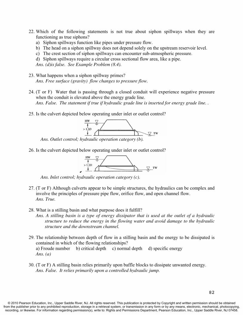
22. Which of the following statements is not true about siphon spillways when they are functioning as true siphons? a) Siphon spillways function like pipes under pressure flow. b) The head on a siphon spillway does not depend solely on the upstream reservoir level. c) The crest section of siphon spillways can encounter sub-atmospheric pressure. d) Siphon spillways require a circular cross sectional flow area, like a pipe.Ans. (d)is false. See Example Problem (8.4).
23. What happens when a siphon spillway primes? Ans. Free surface (gravity) flow changes to pressure flow.
24. (T or F) Water that is passing through a closed conduit will experience negative pressure when the conduit is elevated above the energy grade line. Ans. False. The statement if true if hydraulic grade line is inserted for energy grade line. .
25. Is the culvert depicted below operating under inlet or outlet control?
Ans. Outlet control; hydraulic operation category (b).
26. Is the culvert depicted below operating under inlet or outlet control?
Ans. Inlet control; hydraulic operation category (c).
27. (T or F) Although culverts appear to be simple structures, the hydraulics can be complex and involve the principles of pressure pipe flow, orifice flow, and open channel flow. Ans. True.
28. What is a stilling basin and what purpose does it fulfill? Ans. A stilling basin is a type of energy dissipator that is used at the outlet of a hydraulic
structure to reduce the energy in the flowing water and avoid damage to the hydraulic structure and the downstream channel.
29. The relationship between depth of flow in a stilling basin and the energy to be dissipated is contained in which of the flowing relationships? a) Froude number b) critical depth c) normal depth d) specific energy Ans. (a)
30. (T or F) A stilling basin relies primarily upon baffle blocks to dissipate unwanted energy. Ans. False. It relies primarily upon a controlled hydraulic jump.
82
© 2010 Pearson Education, Inc., Upper Saddle River, NJ. All rights reserved. This publication is protected by Copyright and written permission should be obtainedfrom the publisher prior to any prohibited reproduction, storage in a retrieval system, or transmission in any form or by any means, electronic, mechanical, photocopying,recording, or likewise. For information regarding permission(s), write to: Rights and Permissions Department, Pearson Education, Inc., Upper Saddle River, NJ 07458.
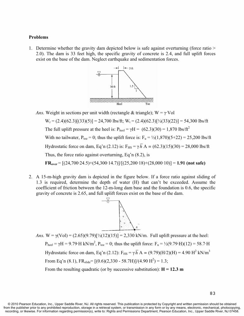
Problems
1. Determine whether the gravity dam depicted below is safe against overturning (force ratio > 2.0). The dam is 33 feet high, the specific gravity of concrete is 2.4, and full uplift forces exist on the base of the dam. Neglect earthquake and sedimentation forces.
Ans. Weight in sections per unit width (rectangle & triangle); W = ·Vol
Wr = (2.4)(62.3)[(33)(5)] = 24,700 lbs/ft; Wt = (2.4)(62.3)[½(33)(22)] = 54,300 lbs/ft
The full uplift pressure at the heel is: Pheel = H = (62.3)(30) = 1,870 lbs/ft2
With no tailwater, Ptoe = 0; thus the uplift force is: Fu = ½(1,870)(5+22) = 25,200 lbs/ft
Hydrostatic force on dam, Eq’n (2.12) is: FHS = h A = (62.3)(15)(30) = 28,000 lbs/ft
Thus, the force ratio against overturning, Eq’n (8.2), is
FRover = [(24,700·24.5)+(54,300·14.7)]/[(25,200·18)+(28,000·10)] = 1.91 (not safe)
2. A 15-m-high gravity dam is depicted in the figure below. If a force ratio against sliding of 1.3 is required, determine the depth of water (H) that can’t be exceeded. Assume the coefficient of friction between the 12-m-long dam base and the foundation is 0.6, the specific gravity of concrete is 2.65, and full uplift forces exist on the base of the dam.
Ans. W = (Vol) = (2.65)(9.79)[½(12)(15)] = 2,330 kN/m. Full uplift pressure at the heel:
Pheel = H = 9.79·H kN/m2, Ptoe = 0; thus the uplift force: Fu = ½(9.79·H)(12) = 58.7·H
Hydrostatic force on dam, Eq’n (2.12): FHS = h A = (9.79)(H/2)(H) = 4.90 H2 kN/m3
From Eq’n (8.1), FRslide= [(0.6)(2,330 - 58.7H)]/(4.90 H2) = 1.3;
From the resulting quadratic (or by successive substitution): H = 12.3 m
83
© 2010 Pearson Education, Inc., Upper Saddle River, NJ. All rights reserved. This publication is protected by Copyright and written permission should be obtainedfrom the publisher prior to any prohibited reproduction, storage in a retrieval system, or transmission in any form or by any means, electronic, mechanical, photocopying,recording, or likewise. For information regarding permission(s), write to: Rights and Permissions Department, Pearson Education, Inc., Upper Saddle River, NJ 07458.

3. A 15-m-high gravity dam is depicted in the figure below. Determine the foundation pressure at the heel and toe of the dam if the water behind the dam rises to a depth of 15 m. Assume the coefficient of friction between the 12-m-long dam base and the foundation is 0.6, the specific gravity of concrete is 2.65, and full uplift forces exist on the base of the dam.
Ans. W = (Vol) = (2.65)(9.79)[½(12)(15)] = 2,330 kN/m. Full uplift pressure at the heel:
Pheel = (15) = 147 kN/m2, Ptoe = 0; thus the uplift force: Fu = ½(147)(12) = 882 kN/m
Thus, the resultant of all vertical forces is: R = 2,330 - 882 = 1,450 kN/m
Find distance of R from the center line (“e”, Fig 8.4): R ·e = MCL; clockwise positive
1450·e = [882·(6.0-(12/3))-2330·(6.0-(12/3))]; e = - 2.00 m; Since counter-clockwise
moments produced by the component forces exceed clockwise moments, the location of
R is on the upstream side of the centerline. Therefore, PH will be greater than PT.
From Eq’n (8.3) revised: PT = (R /B)(1 - 6e/B) = (1450/12)(1 - 6(2)/12) = 0.0 kN/m2
From Eq’n (8.4) revised: PH = (R /B)(1 + 6e/B) = (1450/12)(1 + 6(2)/12) = 242 kN/m2
PT and PH remains positive, however just barely.
4. Determine the flow rate in a 4-m-wide rectangular channel that contains a weir 1.0 m in height if the water depth on the crest of the weir measures 0.3 m. Also, determine the water depth upstream of the weir. Neglect friction loss and the velocity head upstream. Finally, if the velocity head upstream was not neglected, how much would the upstream depth change.
Ans. From Equation (8.8a); q = [g(yc)3]1/2 = [9.81(0.30)3]1/2 = 0.515 m3/sec-m
Q = bq = (0.515)(4) = 2.06 m3/sec
From Equation (8.7); H = (3/2)yc + x = (3/2)(0.3) + 1.0 = 1.45 m
If the upstream velocity head was not neglected, perform an energy balance:
H + V2/2g = (3/2)yc + x; where V = q/H = 0.515/H, therefore
H + (0.515/H)2/2g = (3/2)(0.3) + 1.0 = 1.45; From the resulting quadratic (or by
successive substitution): H = 1.44 m (<0.01 m change).
84
© 2010 Pearson Education, Inc., Upper Saddle River, NJ. All rights reserved. This publication is protected by Copyright and written permission should be obtainedfrom the publisher prior to any prohibited reproduction, storage in a retrieval system, or transmission in any form or by any means, electronic, mechanical, photocopying,recording, or likewise. For information regarding permission(s), write to: Rights and Permissions Department, Pearson Education, Inc., Upper Saddle River, NJ 07458.
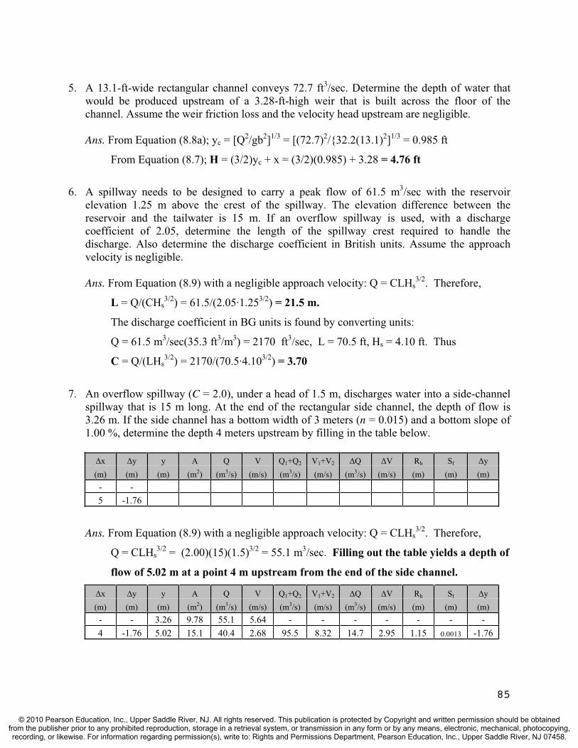
5. A 13.1-ft-wide rectangular channel conveys 72.7 ft3/sec. Determine the depth of water that would be produced upstream of a 3.28-ft-high weir that is built across the floor of the channel. Assume the weir friction loss and the velocity head upstream are negligible.
Ans. From Equation (8.8a); yc = [Q2/gb2]1/3 = [(72.7)2/{32.2(13.1)2]1/3 = 0.985 ft
From Equation (8.7); H = (3/2)yc + x = (3/2)(0.985) + 3.28 = 4.76 ft
6. A spillway needs to be designed to carry a peak flow of 61.5 m3/sec with the reservoir elevation 1.25 m above the crest of the spillway. The elevation difference between the reservoir and the tailwater is 15 m. If an overflow spillway is used, with a discharge coefficient of 2.05, determine the length of the spillway crest required to handle the discharge. Also determine the discharge coefficient in British units. Assume the approach velocity is negligible.
Ans. From Equation (8.9) with a negligible approach velocity: Q = CLHs3/2. Therefore,
L = Q/(CHs3/2) = 61.5/(2.05·1.253/2) = 21.5 m.
The discharge coefficient in BG units is found by converting units:
Q = 61.5 m3/sec(35.3 ft3/m3) = 2170 ft3/sec, L = 70.5 ft, Hs = 4.10 ft. Thus
C = Q/(LHs3/2) = 2170/(70.5·4.103/2) = 3.70
7. An overflow spillway (C = 2.0), under a head of 1.5 m, discharges water into a side-channel spillway that is 15 m long. At the end of the rectangular side channel, the depth of flow is 3.26 m. If the side channel has a bottom width of 3 meters (n = 0.015) and a bottom slope of 1.00 %, determine the depth 4 meters upstream by filling in the table below.
x y y A Q V Q1+Q2 V1+V2 Q V Rh Sf y(m) (m) (m) (m2) (m3/s) (m/s) (m3/s) (m/s) (m3/s) (m/s) (m) (m) (m) - -5 -1.76
Ans. From Equation (8.9) with a negligible approach velocity: Q = CLHs3/2. Therefore,
Q = CLHs3/2 = (2.00)(15)(1.5)3/2 = 55.1 m3/sec. Filling out the table yields a depth of
flow of 5.02 m at a point 4 m upstream from the end of the side channel.
x y y A Q V Q1+Q2 V1+V2 Q V Rh Sf y(m) (m) (m) (m2) (m3/s) (m/s) (m3/s) (m/s) (m3/s) (m/s) (m) (m) (m) - - 3.26 9.78 55.1 5.64 - - - - - - -4 -1.76 5.02 15.1 40.4 2.68 95.5 8.32 14.7 2.95 1.15 0.0013 -1.76
85
© 2010 Pearson Education, Inc., Upper Saddle River, NJ. All rights reserved. This publication is protected by Copyright and written permission should be obtainedfrom the publisher prior to any prohibited reproduction, storage in a retrieval system, or transmission in any form or by any means, electronic, mechanical, photocopying,recording, or likewise. For information regarding permission(s), write to: Rights and Permissions Department, Pearson Education, Inc., Upper Saddle River, NJ 07458.
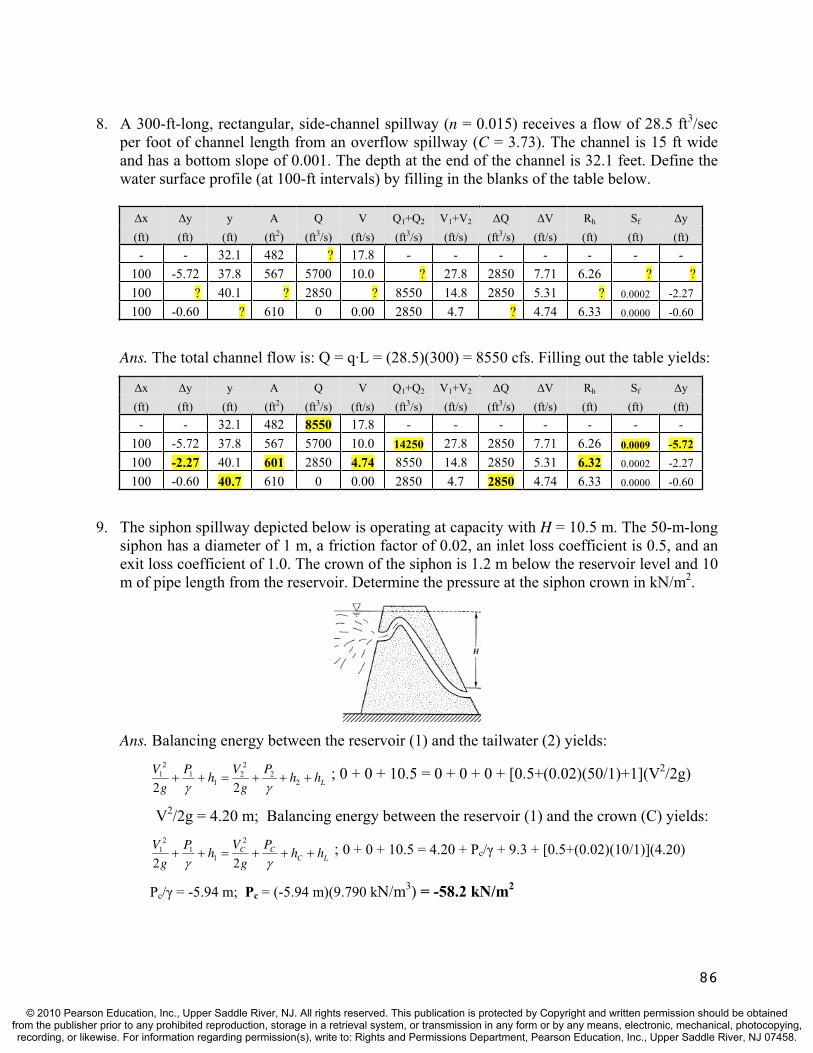
8. A 300-ft-long, rectangular, side-channel spillway (n = 0.015) receives a flow of 28.5 ft3/secper foot of channel length from an overflow spillway (C = 3.73). The channel is 15 ft wide and has a bottom slope of 0.001. The depth at the end of the channel is 32.1 feet. Define the water surface profile (at 100-ft intervals) by filling in the blanks of the table below.
x y y A Q V Q1+Q2 V1+V2 Q V Rh Sf y(ft) (ft) (ft) (ft2) (ft3/s) (ft/s) (ft3/s) (ft/s) (ft3/s) (ft/s) (ft) (ft) (ft)- - 32.1 482 ? 17.8 - - - - - - -
100 -5.72 37.8 567 5700 10.0 ? 27.8 2850 7.71 6.26 ? ?100 ? 40.1 ? 2850 ? 8550 14.8 2850 5.31 ? 0.0002 -2.27 100 -0.60 ? 610 0 0.00 2850 4.7 ? 4.74 6.33 0.0000 -0.60
Ans. The total channel flow is: Q = q·L = (28.5)(300) = 8550 cfs. Filling out the table yields:
x y y A Q V Q1+Q2 V1+V2 Q V Rh Sf y(ft) (ft) (ft) (ft2) (ft3/s) (ft/s) (ft3/s) (ft/s) (ft3/s) (ft/s) (ft) (ft) (ft)- - 32.1 482 8550 17.8 - - - - - - -
100 -5.72 37.8 567 5700 10.0 14250 27.8 2850 7.71 6.26 0.0009 -5.72
100 -2.27 40.1 601 2850 4.74 8550 14.8 2850 5.31 6.32 0.0002 -2.27 100 -0.60 40.7 610 0 0.00 2850 4.7 2850 4.74 6.33 0.0000 -0.60
9. The siphon spillway depicted below is operating at capacity with H = 10.5 m. The 50-m-long siphon has a diameter of 1 m, a friction factor of 0.02, an inlet loss coefficient is 0.5, and an exit loss coefficient of 1.0. The crown of the siphon is 1.2 m below the reservoir level and 10 m of pipe length from the reservoir. Determine the pressure at the siphon crown in kN/m2.
Ans. Balancing energy between the reservoir (1) and the tailwater (2) yields:
LhhP
g
Vh
P
g
V2
22
21
12
1
22 ; 0 + 0 + 10.5 = 0 + 0 + 0 + [0.5+(0.02)(50/1)+1](V2/2g)
V2/2g = 4.20 m; Balancing energy between the reservoir (1) and the crown (C) yields:
LCCC hh
P
g
Vh
P
g
V
22
2
11
21 ; 0 + 0 + 10.5 = 4.20 + Pc/ + 9.3 + [0.5+(0.02)(10/1)](4.20)
Pc/ = -5.94 m; Pc = (-5.94 m)(9.790 kN/m3) = -58.2 kN/m2
86
© 2010 Pearson Education, Inc., Upper Saddle River, NJ. All rights reserved. This publication is protected by Copyright and written permission should be obtainedfrom the publisher prior to any prohibited reproduction, storage in a retrieval system, or transmission in any form or by any means, electronic, mechanical, photocopying,recording, or likewise. For information regarding permission(s), write to: Rights and Permissions Department, Pearson Education, Inc., Upper Saddle River, NJ 07458.

10. At design conditions, a 25-m-wide overflow spillway (C = 2.0) operates under a headwater of 1 m. The downstream pool is 14 m below the overflow spillway crest. A siphon spillway is being considered as an alternative to the overflow spillway. Determine the width of a rectangular siphon spillway that has a 1-m opening height and discharges the same flow rate at the same reservoir elevation. Assume the siphon losses are 5(V2/2g).
Ans. From Equation (8.9): Q = CLHs3/2 = (2.00)(25)(1.0)3/2 = 50.0 m3/sec.
Balancing energy between the reservoir (1) and the downstream pool (2) yields:
LhhP
g
Vh
P
g
V2
22
21
12
1
22 ; 0 + 0 + 15.0 = 0 + 0 + 0 + 5(V2/2g); V = 7.67 m/sec;
A = Q/V = 50/7.67 = 6.52 m2; with a height of 1 m, the width is: W = 6.52 m
11. A 2 m by 2 m concrete culvert with a square-edged entrance condition is 15 m long and has a bottom slope of 2.0%. Determine the water depth upstream necessary to pass a 12.5 m3/secdesign flow if the tail water depth is 2.75 m above the bottom of the box culvert at the outlet.
Ans. Since the outlet is submerged, the head loss from hydraulic operation category (a) is
hL = [Ke + {n2L/Rh4/3}(2g) + 1]{Q2/(2g·A2)}; Rh = A/P = (4 m2)/(8 m) = 0.5 m
hL = [0.5 + {0.0132(15)/(0.5)4/3}(2·9.81) + 1]{12.52/(2·9.81·(42)} = 0.81 m
Balancing energy between the entrance and the exit yields:
H + SoL = 2.75 + hL; H + (0.02)(15) = 2.75 + 0.81; H = 3.26 m
12. During a flood event, the water level upstream of a 4-ft-diameter, corrugated metal highway culvert (square-edged entrance) rises to a depth that is 4.6 feet above the top of the barrel. The culvert is 200 ft long with a slope of 5.0%. If the outlet of the culvert was not submerged during the flood event, determine the flow rate that was passing through the culvert.
Ans. Based on the design conditions (submerged inlet, but unsubmerged outlet) the culvert
must be hydraulic operation category (b) or (c). For category (b), the energy balance is:
hL = H + SoL – D = (4.0 + 4.6) + (0.05)(200) – 4.0 = 14.6 ft. For full pipe flow, hL is:
hL = [Ke + {n2L/(D/4)4/3}(2g) + 1]{8Q2/( 2gD4)}
14.6 = [0.5 + {0.0242(200)/(4/4)4/3}(2·32.2) + 1]{8·Q2/( 2·32.2·4.04)}; Q = 129 cfs
If the culvert is operating under partially full flow (hydraulic category (c)), then
Q = CdA(2gh)1/2 with h = H – D/2 = (4.0 + 4.6) – (4.0/2) = 6.6 ft. Therefore,
Q = (0.6)( ·42/4)[2·32.2·(6.6)]1/2 = 155 cfs. Thus, Q = 129 cfs (outlet control)
87
© 2010 Pearson Education, Inc., Upper Saddle River, NJ. All rights reserved. This publication is protected by Copyright and written permission should be obtainedfrom the publisher prior to any prohibited reproduction, storage in a retrieval system, or transmission in any form or by any means, electronic, mechanical, photocopying,recording, or likewise. For information regarding permission(s), write to: Rights and Permissions Department, Pearson Education, Inc., Upper Saddle River, NJ 07458.
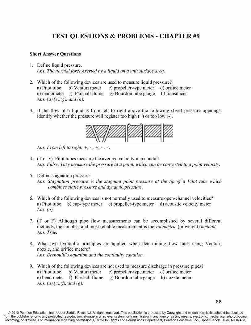
TEST QUESTIONS & PROBLEMS - CHAPTER #9
Short Answer Questions
1. Define liquid pressure.Ans. The normal force exerted by a liquid on a unit surface area.
2. Which of the following devices are used to measure liquid pressure? a) Pitot tube b) Venturi meter c) propeller-type meter d) orifice meter e) manometer f) Parshall flume g) Bourdon tube gauge h) transducerAns. (a),(e),(g), and (h).
3. If the flow of a liquid is from left to right above the following (five) pressure openings, identify whether the pressure will register too high (+) or too low (-).
Ans. From left to right: +, - , +, - , - .
4. (T or F) Pitot tubes measure the average velocity in a conduit.Ans. False. They measure the pressure at a point, which can be converted to a point velocity.
5. Define stagnation pressure.Ans. Stagnation pressure is the stagnant point pressure at the tip of a Pitot tube which
combines static pressure and dynamic pressure.
6. Which of the following devices is not normally used to measure open-channel velocities? a) Pitot tube b) cup-type meter c) propeller-type meter d) acoustic velocity meter Ans. (a).
7. (T or F) Although pipe flow measurements can be accomplished by several different methods, the simplest and most reliable measurement is the volumetric (or weight) method.Ans. True.
8. What two hydraulic principles are applied when determining flow rates using Venturi, nozzle, and orifice meters? Ans. Bernoulli’s equation and the continuity equation.
9. Which of the following devices are not used to measure discharge in pressure pipes? a) Pitot tube b) Venturi meter c) propeller-type meter d) orifice meter e) bend meter f) Parshall flume g) Bourdon tube gauge h) nozzle meter Ans. (a),(c),(f), and (g).
88
© 2010 Pearson Education, Inc., Upper Saddle River, NJ. All rights reserved. This publication is protected by Copyright and written permission should be obtainedfrom the publisher prior to any prohibited reproduction, storage in a retrieval system, or transmission in any form or by any means, electronic, mechanical, photocopying,recording, or likewise. For information regarding permission(s), write to: Rights and Permissions Department, Pearson Education, Inc., Upper Saddle River, NJ 07458.
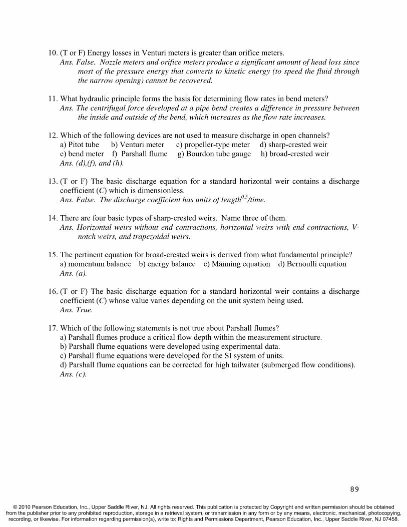
10. (T or F) Energy losses in Venturi meters is greater than orifice meters. Ans. False. Nozzle meters and orifice meters produce a significant amount of head loss since
most of the pressure energy that converts to kinetic energy (to speed the fluid through the narrow opening) cannot be recovered.
11. What hydraulic principle forms the basis for determining flow rates in bend meters? Ans. The centrifugal force developed at a pipe bend creates a difference in pressure between
the inside and outside of the bend, which increases as the flow rate increases.
12. Which of the following devices are not used to measure discharge in open channels? a) Pitot tube b) Venturi meter c) propeller-type meter d) sharp-crested weire) bend meter f) Parshall flume g) Bourdon tube gauge h) broad-crested weirAns. (d),(f), and (h).
13. (T or F) The basic discharge equation for a standard horizontal weir contains a discharge coefficient (C) which is dimensionless. Ans. False. The discharge coefficient has units of length0.5/time.
14. There are four basic types of sharp-crested weirs. Name three of them. Ans. Horizontal weirs without end contractions, horizontal weirs with end contractions, V-
notch weirs, and trapezoidal weirs.
15. The pertinent equation for broad-crested weirs is derived from what fundamental principle? a) momentum balance b) energy balance c) Manning equation d) Bernoulli equation Ans. (a).
16. (T or F) The basic discharge equation for a standard horizontal weir contains a discharge coefficient (C) whose value varies depending on the unit system being used.Ans. True.
17. Which of the following statements is not true about Parshall flumes? a) Parshall flumes produce a critical flow depth within the measurement structure. b) Parshall flume equations were developed using experimental data. c) Parshall flume equations were developed for the SI system of units. d) Parshall flume equations can be corrected for high tailwater (submerged flow conditions). Ans. (c).
89
© 2010 Pearson Education, Inc., Upper Saddle River, NJ. All rights reserved. This publication is protected by Copyright and written permission should be obtainedfrom the publisher prior to any prohibited reproduction, storage in a retrieval system, or transmission in any form or by any means, electronic, mechanical, photocopying,recording, or likewise. For information regarding permission(s), write to: Rights and Permissions Department, Pearson Education, Inc., Upper Saddle River, NJ 07458.
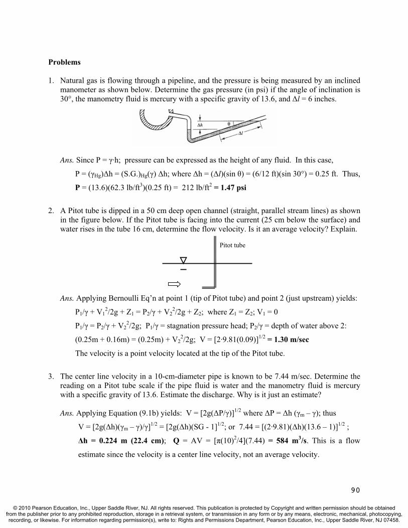
Problems
1. Natural gas is flowing through a pipeline, and the pressure is being measured by an inclined manometer as shown below. Determine the gas pressure (in psi) if the angle of inclination is 30°, the manometry fluid is mercury with a specific gravity of 13.6, and l = 6 inches.
Ans. Since P = ·h; pressure can be expressed as the height of any fluid. In this case,
P = ( Hg) h = (S.G.)Hg( ) h; where h = ( l)(sin ) = (6/12 ft)(sin 30°) = 0.25 ft. Thus,
P = (13.6)(62.3 lb/ft3)(0.25 ft) = 212 lb/ft2 = 1.47 psi
2. A Pitot tube is dipped in a 50 cm deep open channel (straight, parallel stream lines) as shown in the figure below. If the Pitot tube is facing into the current (25 cm below the surface) and water rises in the tube 16 cm, determine the flow velocity. Is it an average velocity? Explain.
Pitot tube
Ans. Applying Bernoulli Eq’n at point 1 (tip of Pitot tube) and point 2 (just upstream) yields:
P1/ + V12/2g + Z1 = P2/ + V2
2/2g + Z2; where Z1 = Z2; V1 = 0
P1/ = P2/ + V22/2g; P1/ = stagnation pressure head; P2/ = depth of water above 2:
(0.25m + 0.16m) = (0.25m) + V22/2g; V = [2·9.81(0.09)]1/2 = 1.30 m/sec
The velocity is a point velocity located at the tip of the Pitot tube.
3. The center line velocity in a 10-cm-diameter pipe is known to be 7.44 m/sec. Determine the reading on a Pitot tube scale if the pipe fluid is water and the manometry fluid is mercury with a specific gravity of 13.6. Estimate the discharge. Why is it just an estimate?
Ans. Applying Equation (9.1b) yields: V = [2g( P/ )]1/2 where P = h ( m – ); thus
V = [2g( h)( m – )/ ]1/2 = [2g( h)(SG - 1]1/2; or 7.44 = [(2·9.81)( h)(13.6 – 1)]1/2 ;
h = 0.224 m (22.4 cm); Q = AV = [ (10)2/4](7.44) = 584 m3/s. This is a flow
estimate since the velocity is a center line velocity, not an average velocity.
90
© 2010 Pearson Education, Inc., Upper Saddle River, NJ. All rights reserved. This publication is protected by Copyright and written permission should be obtainedfrom the publisher prior to any prohibited reproduction, storage in a retrieval system, or transmission in any form or by any means, electronic, mechanical, photocopying,recording, or likewise. For information regarding permission(s), write to: Rights and Permissions Department, Pearson Education, Inc., Upper Saddle River, NJ 07458.
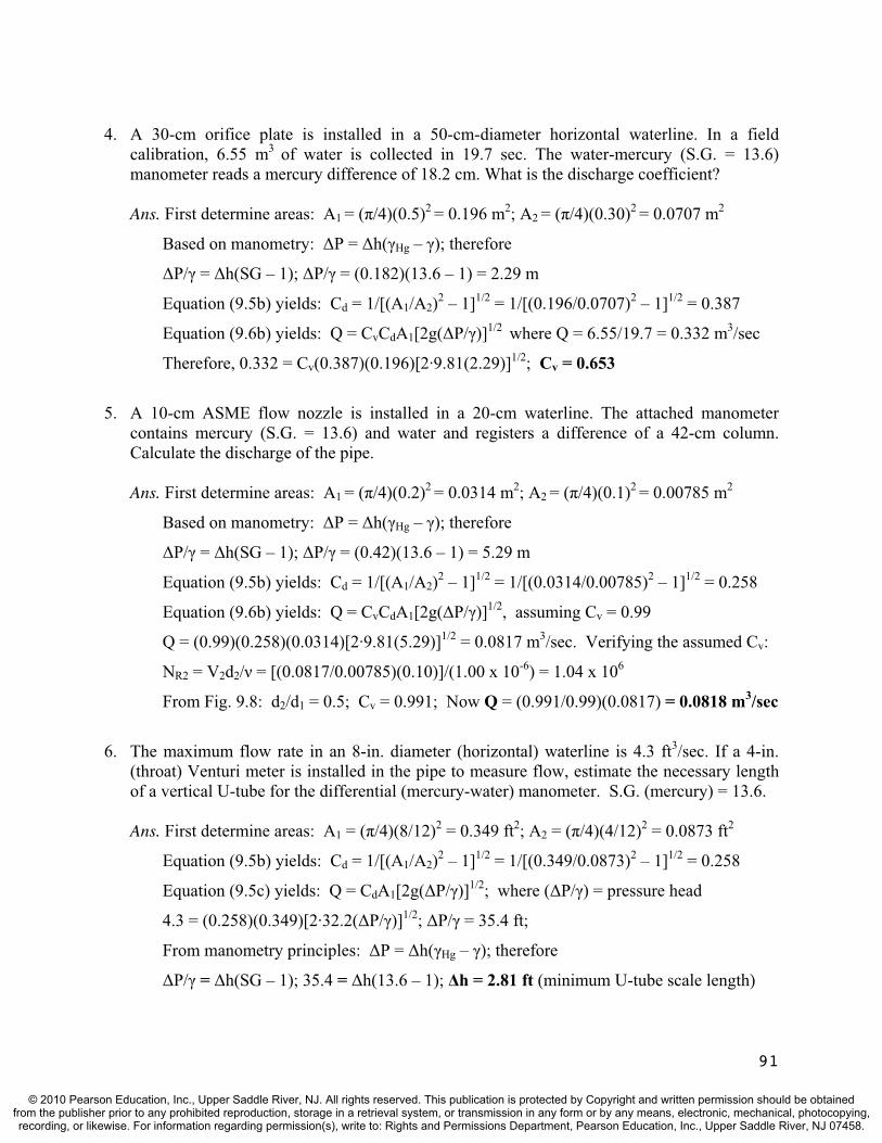
4. A 30-cm orifice plate is installed in a 50-cm-diameter horizontal waterline. In a field calibration, 6.55 m3 of water is collected in 19.7 sec. The water-mercury (S.G. = 13.6) manometer reads a mercury difference of 18.2 cm. What is the discharge coefficient?
Ans. First determine areas: A1 = ( /4)(0.5)2 = 0.196 m2; A2 = ( /4)(0.30)2 = 0.0707 m2
Based on manometry: P = h( Hg – ); therefore
P/ = h(SG – 1); P/ = (0.182)(13.6 – 1) = 2.29 m
Equation (9.5b) yields: Cd = 1/[(A1/A2)2 – 1]1/2 = 1/[(0.196/0.0707)2 – 1]1/2 = 0.387
Equation (9.6b) yields: Q = CvCdA1[2g( P/ )]1/2 where Q = 6.55/19.7 = 0.332 m3/sec
Therefore, 0.332 = Cv(0.387)(0.196)[2·9.81(2.29)]1/2; Cv = 0.653
5. A 10-cm ASME flow nozzle is installed in a 20-cm waterline. The attached manometer contains mercury (S.G. = 13.6) and water and registers a difference of a 42-cm column. Calculate the discharge of the pipe.
Ans. First determine areas: A1 = ( /4)(0.2)2 = 0.0314 m2; A2 = ( /4)(0.1)2 = 0.00785 m2
Based on manometry: P = h( Hg – ); therefore
P/ = h(SG – 1); P/ = (0.42)(13.6 – 1) = 5.29 m
Equation (9.5b) yields: Cd = 1/[(A1/A2)2 – 1]1/2 = 1/[(0.0314/0.00785)2 – 1]1/2 = 0.258
Equation (9.6b) yields: Q = CvCdA1[2g( P/ )]1/2, assuming Cv = 0.99
Q = (0.99)(0.258)(0.0314)[2·9.81(5.29)]1/2 = 0.0817 m3/sec. Verifying the assumed Cv:
NR2 = V2d2/ = [(0.0817/0.00785)(0.10)]/(1.00 x 10-6) = 1.04 x 10⁶
From Fig. 9.8: d2/d1 = 0.5; Cv = 0.991; Now Q = (0.991/0.99)(0.0817) = 0.0818 m3/sec
6. The maximum flow rate in an 8-in. diameter (horizontal) waterline is 4.3 ft3/sec. If a 4-in. (throat) Venturi meter is installed in the pipe to measure flow, estimate the necessary length of a vertical U-tube for the differential (mercury-water) manometer. S.G. (mercury) = 13.6.
Ans. First determine areas: A1 = ( /4)(8/12)2 = 0.349 ft2; A2 = ( /4)(4/12)2 = 0.0873 ft2
Equation (9.5b) yields: Cd = 1/[(A1/A2)2 – 1]1/2 = 1/[(0.349/0.0873)2 – 1]1/2 = 0.258
Equation (9.5c) yields: Q = CdA1[2g( P/ )]1/2; where ( P/ ) = pressure head
4.3 = (0.258)(0.349)[2·32.2( P/ )]1/2; P/ = 35.4 ft;
From manometry principles: P = h( Hg – ); therefore
P/ = h(SG – 1); 35.4 = h(13.6 – 1); h = 2.81 ft (minimum U-tube scale length)
91
© 2010 Pearson Education, Inc., Upper Saddle River, NJ. All rights reserved. This publication is protected by Copyright and written permission should be obtainedfrom the publisher prior to any prohibited reproduction, storage in a retrieval system, or transmission in any form or by any means, electronic, mechanical, photocopying,recording, or likewise. For information regarding permission(s), write to: Rights and Permissions Department, Pearson Education, Inc., Upper Saddle River, NJ 07458.
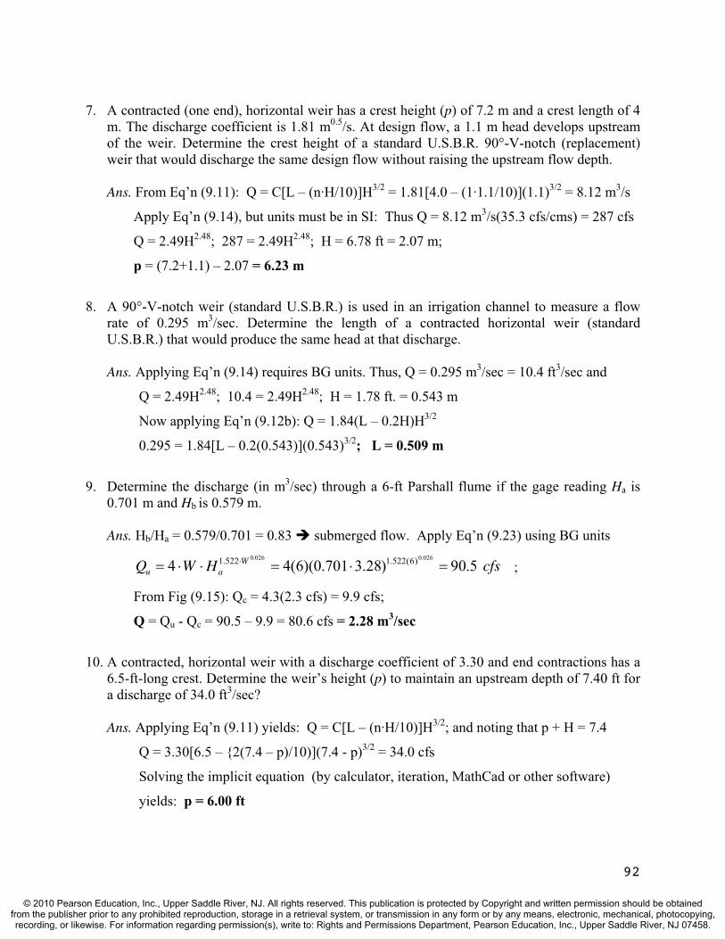
7. A contracted (one end), horizontal weir has a crest height (p) of 7.2 m and a crest length of 4 m. The discharge coefficient is 1.81 m0.5/s. At design flow, a 1.1 m head develops upstream of the weir. Determine the crest height of a standard U.S.B.R. 90°-V-notch (replacement) weir that would discharge the same design flow without raising the upstream flow depth.
Ans. From Eq’n (9.11): Q = C[L – (n·H/10)]H3/2 = 1.81[4.0 – (1·1.1/10)](1.1)3/2 = 8.12 m3/s
Apply Eq’n (9.14), but units must be in SI: Thus Q = 8.12 m3/s(35.3 cfs/cms) = 287 cfs
Q = 2.49H2.48; 287 = 2.49H2.48; H = 6.78 ft = 2.07 m;
p = (7.2+1.1) – 2.07 = 6.23 m
8. A 90°-V-notch weir (standard U.S.B.R.) is used in an irrigation channel to measure a flow rate of 0.295 m3/sec. Determine the length of a contracted horizontal weir (standard U.S.B.R.) that would produce the same head at that discharge.
Ans. Applying Eq’n (9.14) requires BG units. Thus, Q = 0.295 m3/sec = 10.4 ft3/sec and
Q = 2.49H2.48; 10.4 = 2.49H2.48; H = 1.78 ft. = 0.543 m
Now applying Eq’n (9.12b): Q = 1.84(L – 0.2H)H3/2
0.295 = 1.84[L – 0.2(0.543)](0.543)3/2; L = 0.509 m
9. Determine the discharge (in m3/sec) through a 6-ft Parshall flume if the gage reading Ha is 0.701 m and Hb is 0.579 m.
Ans. Hb/Ha = 0.579/0.701 = 0.83 submerged flow. Apply Eq’n (9.23) using BG units
cfsHWQ Wau 5.90)28.3701.0)(6(44
026.0026.0 )6(522.1522.1 ;
From Fig (9.15): Qc = 4.3(2.3 cfs) = 9.9 cfs;
Q = Qu - Qc = 90.5 – 9.9 = 80.6 cfs = 2.28 m3/sec
10. A contracted, horizontal weir with a discharge coefficient of 3.30 and end contractions has a 6.5-ft-long crest. Determine the weir’s height (p) to maintain an upstream depth of 7.40 ft for a discharge of 34.0 ft3/sec?
Ans. Applying Eq’n (9.11) yields: Q = C[L – (n·H/10)]H3/2; and noting that p + H = 7.4
Q = 3.30[6.5 – {2(7.4 – p)/10)](7.4 - p)3/2 = 34.0 cfs
Solving the implicit equation (by calculator, iteration, MathCad or other software)
yields: p = 6.00 ft
92
© 2010 Pearson Education, Inc., Upper Saddle River, NJ. All rights reserved. This publication is protected by Copyright and written permission should be obtainedfrom the publisher prior to any prohibited reproduction, storage in a retrieval system, or transmission in any form or by any means, electronic, mechanical, photocopying,recording, or likewise. For information regarding permission(s), write to: Rights and Permissions Department, Pearson Education, Inc., Upper Saddle River, NJ 07458.

TEST QUESTIONS & PROBLEMS - CHAPTER #10
Short Answer Questions
1. Define dimensional analysis. Ans. Assessment of the appropriate physical quantities and fundamental hydraulic
relationships (both static and dynamic) involved in the performance of the structure.
2. (T or F) The reduced version of a hydraulic structure used to study complex hydrostatic and hydrodynamic phenomena is called a prototype.Ans. False. It is called a scaled model or simply a model.
3. Name three hydraulic structures that are designed or analyzed with the help of model studies. Ans. Spillways, weirs, energy dissipaters, intake structures, transition sections, cooling
ponds, docks, locks, breakwaters, transportation facilities, offshore structures, etc..
4. Which of the following is not one of the three basic forms of hydraulic similitude? a) geometric b) kinetic c) kinematic d) dynamic Ans. (b).
5. Identify the three basic forms of hydraulic similitude. Ans. Geometric, kinematic, and dynamic.
6. Which of the following is not one of the parameter ratios applicable to geometric similarity? a) velocity b) length c) area d) volume Ans. (a).
7. (T or F) Kinematic similarity between a model and prototype is attained if the homologous moving particles have the same velocity ratio along geometrically similar paths. Ans. True.
8. Which of the following is not one of the parameter ratios applicable to kinematic similarity? a) angular acceleration b) discharge c) velocity d) mass e) time Ans. (d).
9. (T or F) Dynamic similarity between a model and its prototype is attained if the ratio of homologous forces (prototype to model) is kept at a constant value. Ans. True.
10. When inertial forces and viscous forces govern fluid motion, which dimensionless ratio must be maintained between the model and the prototype?? a) Reynolds number b) Froude number c) Weber number d) Social Security number Ans. (a).
93
© 2010 Pearson Education, Inc., Upper Saddle River, NJ. All rights reserved. This publication is protected by Copyright and written permission should be obtainedfrom the publisher prior to any prohibited reproduction, storage in a retrieval system, or transmission in any form or by any means, electronic, mechanical, photocopying,recording, or likewise. For information regarding permission(s), write to: Rights and Permissions Department, Pearson Education, Inc., Upper Saddle River, NJ 07458.

11. Based on the Reynolds number law (i.e., ratio), determine the dimensions for the velocity ratio if the same fluid is used in the model and in the prototype.Ans. The Reynolds number law (for r = 1, r = 1) is ( rLrVr)/ r = LrVr = 1. Therefore,
Vr = 1/Lr = Lr-1
12. Based on the Reynolds number law (i.e., ratio), determine the dimensions for the time ratio if the same fluid is used in the model and in the prototype.Ans. The Reynolds number law (for r = 1, r = 1) is ( rLrVr)/ r = LrVr = 1. Therefore, Vr = 1/Lr = Lr
-1 and from Eq’n (10.6): Vr = Lr/Tr thus Lr-1 = Lr/Tr; Tr = Lr
2
13. When inertial forces and gravity forces govern fluid motion, which dimensionless ratio must be maintained between the model and the prototype?? a) Reynolds number b) Froude number c) Weber number d) Social Security number Ans. (b).
14. Based on the Froude number law (i.e., ratio), determine the dimensions for the velocity ratio if the same fluid is used in the model and in the prototype. Ans. The Froude number law (for gr = 1, r = 1) is (Vr)/(gr
1/2Lr1/2) = (Vr)/(Lr
1/2) = 1. Therefore, Vr = Lr
1/2
15. Based on the Froude number law (i.e., ratio), determine the dimensions for the time ratio if the same fluid is used in the model and in the prototype.Ans. The Froude number law (for gr = 1, r = 1) is (Vr)/(gr
1/2Lr1/2) = (Vr)/(Lr
1/2) = 1. Therefore, Vr = Lr
1/2 and from Eq’n (10.6): Vr = Lr/Tr; Lr1/2 = Lr/Tr; Tr = Lr
1/2
16. When surface tension forces are prominent, which dimensionless ratio must be maintained between the model and the prototype?? a) Reynolds number b) Froude number c) Weber number d) Social Security number Ans. (c).
17. Based on the Weber number law (i.e., ratio), determine the dimensions for the velocity ratio if the same fluid is used in the model and in the prototype. Ans. The Weber number law (for r = 1, r = 1) is ( rVr
2Lr)/ r = Vr2Lr = 1.
Therefore, Vr = 1/Lr1/2
18. Based on the Weber number law (i.e., ratio), determine the dimensions for the time ratio if the same fluid is used in the model and in the prototype.Ans. The Weber number law (for r = 1, r = 1) is ( rVr
2Lr)/ r = Vr2Lr = 1.
Therefore, Vr = 1/Lr1/2 and from Eq’n (10.6): Vr = Lr/Tr; 1/Lr
1/2 = Lr/Tr; Tr = Lr3/2
19. When both gravity and viscous forces are prominent, which dimensionless ratio(s) must be maintained between the model and the prototype?? a) Reynolds number b) Froude number c) Weber number d) Social Security number Ans. (a) and (b).
94
© 2010 Pearson Education, Inc., Upper Saddle River, NJ. All rights reserved. This publication is protected by Copyright and written permission should be obtainedfrom the publisher prior to any prohibited reproduction, storage in a retrieval system, or transmission in any form or by any means, electronic, mechanical, photocopying,recording, or likewise. For information regarding permission(s), write to: Rights and Permissions Department, Pearson Education, Inc., Upper Saddle River, NJ 07458.

20. (T or F) To determine the friction drag along the boundary of a floating or submerged vessel, the Reynolds number ratio must be maintained between the model and the prototype. Ans. True.
21. To determine the force expended in the generation of gravity waves on a floating vessel, which dimensionless ratio(s) must be maintained between the model and the prototype?? a) Reynolds number b) Froude number c) Weber number d) Social Security number Ans. (b).
22. Identify two different kinds of problems that can be analyzed using open channel models. Ans. Velocity-slope relationships and channel bed movement due to flow patterns.
23. (T or F) Open channel models generally use the same vertical and horizontal scales.Ans. False.
24. Show that the Manning velocity ratio for an undistorted open channel model equals Lr2/3/nr.
Ans. From the Manning equation: Vr = (1/nr)Rhr2/3Sr
1/2; but Sr= 1 (undistorted) and Rhr = Lr; Therefore, Vr = Lr
2/3/nr
25. Identify the equation that relates mass in the MLT system to force in the FLT system. Ans. Newton’s 2nd law, F = ma.
26. Dimensional analysis produces many advantages in solving complex hydraulic problems. These advantages include all of the following except: a) provides an appropriate solution to the complex problem, b) reduces the number of pertinent variables by forming dimensionless groupings, c) provides a guide to point out applicable relationships among the parameters, and d) reduces the complexity of the model experiments necessary to identify the solution.Ans. (a).
27. Define repeating variable as the term applies to dimensional analysis using the Pi-theorem? Ans. Pertinent variables that will appear in each of the dimensionless –groups.
28. Identify two dimensionless parameters that commonly appear in hydraulic model studies. Ans. The Reynolds number, the Froude number, and the Weber number.
29. (T or F) The Buckingham Pi-theorem states that if a physical phenomenon involves ndimensional variables in a dimensionally homogenous equation described by m fundamental dimensions, the variables may be combined into (n – m) dimensionless groups for analysis. Ans. True.
95
© 2010 Pearson Education, Inc., Upper Saddle River, NJ. All rights reserved. This publication is protected by Copyright and written permission should be obtainedfrom the publisher prior to any prohibited reproduction, storage in a retrieval system, or transmission in any form or by any means, electronic, mechanical, photocopying,recording, or likewise. For information regarding permission(s), write to: Rights and Permissions Department, Pearson Education, Inc., Upper Saddle River, NJ 07458.

Problems
1. A 650 m long channel carries irrigation water at an average velocity of 2 m/sec. The trapezoidal channel has a 2 m depth, 4.25 m bottom width, and 1:1 side slopes. Determine the velocity and discharge of a geometrically similar model constructed with a 10:1 scale.
Ans. Since A = (b + my)y = [4.25 + (1)2](2) = 12.5 m2; Q = AV = (12.5)(2) = 25.0 m3/sec.
The area ratio between prototype and model using Equation (10.3) is:
Thus, Ap/Am = (Lp2/Lm
2) = Lr2. The velocity ratio is found using
Vp/Vm = (Lp/Tp)/(Lm/Tm) = (Lp)/(Lm) = Lr. Note that for geometric similarity, the time
ratio from the prototype to the model is unscaled. Thus, the model velocity is
Vp/Vm = Lr; Vm = Vp/Lr = (2 m/sec)/10 = 0.20 m/sec. Also, the discharge ratio is
Qp/Qm = (Ap·Vp)/(Am·Vm) = (Lr2)( Lr) = Lr
3.
Qm = Qp/Lr3 = (25.0)/1000 = 0.025 m3/sec
2. An 328-ft-long overflow spillway will discharge flood water from a reservoir under a permitted maximum head of 9.85 ft. The operation of the prototype spillway is studied on a 1:50 scale model in a hydraulic laboratory. The spillway discharge is governed by the equation: Q = CLH3/2, where C is the coefficient of discharge, L is the spillway length, and His the head on the spillway. If the model discharge is 2.30 ft3/sec, determine the discharge in the prototype. Also determine the velocity measured at the end (toe) of the spillway if the velocity at the same location in the model is 9.85 ft/sec. Assume the discharge coefficient ratio between prototype and model is one.
Ans. Kinematic similarity seems appropriate since time is involved, but not force. To
determine a time scale, Q = CLH3/2 where Q = spillway discharge. Thus,
Qp/Qm = (Cp/Cm)(Lp/Lm)[(Hp/Hm)]3/2; Qr = Lr3/Tr = (Lp/Lm)[(Hp/Hm)]3/2 = Lr(Lr)3/2
since Cp/Cm = 1. Therefore, Lr3/Tr = Lr(Lr)3/2; Tr = Lr
1/2 = (50)1/2 = 7.07; Hence,
Qr = Qp/Qm = Lr3/Tr = (50)3/7.07 = 17,700;
Qp = (2.30)(17,700) = 4.07 x 104 ft3/sec
Also, Vr = Vp/Vm = Lr/Tr = 50/7.07 = 7.07; and Vp = (9.85)(7.07) = 69.6 ft/sec
3. An overflow spillway with a 100-m-long crest will convey a design discharge of 1150 m3/secunder a permitted maximum head of 3.00 m. The operation of the prototype spillway is studied on a 1:50 scale model in a hydraulic laboratory. The flow rate in the model is 0.0650 m3/sec. If the force on a bucket energy dissipater at the toe of the spillway model is measured to be 37.5 N, determine the corresponding force on the prototype.
96
© 2010 Pearson Education, Inc., Upper Saddle River, NJ. All rights reserved. This publication is protected by Copyright and written permission should be obtainedfrom the publisher prior to any prohibited reproduction, storage in a retrieval system, or transmission in any form or by any means, electronic, mechanical, photocopying,recording, or likewise. For information regarding permission(s), write to: Rights and Permissions Department, Pearson Education, Inc., Upper Saddle River, NJ 07458.

Ans. Dynamic similarity is appropriate since force is involved. From Equation (10.13):
Fr = Fp/Fm = rLr4Tr
-2. Therefore, Tr must be obtained from Equation (10.8):
Qp/Qm = Lr3/Tr; 1150/0.0650 = 503/Tr; Tr = 7.07. Therefore, assuming r = 1.0,
Fp/Fm = rLr4Tr
-2; Fp/37.5 = (1.0)(50)4(7.07)-2; Fp = 4,690 kN
4. A 1:25 scale model is being designed to study a prototype hydraulic structure. The velocity ratio between the model and the prototype is 1:5, and the measurement accuracy is required to be within 1% of the total force. Determine the model force and the accuracy of the force measurement in the model if the expected force on the prototype is 45,000 N.
Ans. Dynamic similarity is appropriate since force is involved. Based on the given data:
Vr = Lr/Tr; 5.0 = 25/Tr; Tr = 5.0. Assuming r = 1.0, Equation (10.13) yields
Fr = Fp/Fm = rLr4Tr
-2 = (1)(25)4(5)-2 = 1.56 x 10⁴. Therefore,
Fr = Fp/Fm; 1.56 x 104 = 45,000/Fm; Fm = 2.88 N. Now, the error in the force is
Ep = (0.01)(45,000) = 450 N. Em = Ep/Fr = 450/(1.56 x 104) = 0.0288 N
5. For a particular hydraulic model study, the inertial forces and the viscous forces are known to govern the motion. If the model and prototype are using the same fluid, verify the scale ratios for a) time (Tr = Lr
2), b) angular velocity (Nr = Lr-2), and c) force (Fr = 1).
Ans. The Reynolds Number Law (for r = 1, r = 1) is ( rLrVr)/ r = LrVr = 1. Therefore,
a) Vr = 1/Lr = Lr-1; and since from Eq’n (10.6): Vr = Lr/Tr; Lr
-1 = Lr/Tr; Tr = Lr2
b) From Eq’n (10.10): Nr = 1/Tr = 1/Lr2 = Lr
-2
c) Eq’n (10.13): Fr = rLr4Tr
-2 = Lr4(Lr
2)-2 = 1
6. A Reynolds number scale model is used to study the operation of a prototype hydraulic device. The 1:5 scale model uses water at 20°C. The prototype discharges 11.5 m3/sec of water at 90°C ( p = 965 kg/m3; p = 3.15 x 10⁻⁴ N·s/m2). Determine the model discharge.
Ans. At 20°C ( m = 998 kg/m3; p = 1.00 x 10⁻³ N·s/m2). Use the Reynolds Number Law
where r = 965/998 = 0.967 and r = 0.315/1.00 = 0.315.
Therefore, ( rLrVr)/ r = 1 or [(0.967)(5)(Vr)/(0.315) = 1; Vr = 0.0651
Since Q = AV; dimensionally, Qr = (Lr)2(Vr) = (5)2(0.0651) = 1.63
Thus, Qr = Qp/Qm or Qm = Qp/Qr = 11.5/1.63 = 7.06 m3/sec
97
© 2010 Pearson Education, Inc., Upper Saddle River, NJ. All rights reserved. This publication is protected by Copyright and written permission should be obtainedfrom the publisher prior to any prohibited reproduction, storage in a retrieval system, or transmission in any form or by any means, electronic, mechanical, photocopying,recording, or likewise. For information regarding permission(s), write to: Rights and Permissions Department, Pearson Education, Inc., Upper Saddle River, NJ 07458.

7. A ship 300 ft long designed to travel at a top speed of 3 ft/sec is to be studied in a towing tank with a 1:50 scale model. Determine what speed the model must be towed for (a) the Reynolds number law and (b) the Froude number law.
Ans. a) Using the Reynolds Number Law (for r = 1, r = 1), from Table 10.2 we have,
Vm = Vp/Vr = Vp/(Lr)-1 = 3/(50)-1 = 150 ft/sec
b) Using the Froude Number Law (for gr = 1, r = 1), from Table 10.3 we have,
Vm = Vp/Vr = Vp/(Lr)1/2 = 3/(50)1/2 = 0.424 ft/sec
8. A 120-m-long overflow spillway will discharge flood water from a reservoir with a permitted maximum head of 2.75 m. The operation of the prototype spillway is studied on a 1:50 scale model in a hydraulic laboratory. Assuming inertial and gravity forces dominate, determine the discharge of the prototype if the model discharge is 67.9 L/sec. In addition, assume the spillway discharge is governed by the equation: Q = CLH3/2, where C is the coefficient of discharge, L is the spillway length, and H is the spillway head. If the discharge coefficient of the model crest measures 2.19, what is the prototype crest discharge coefficient?
Ans. a) For inertial and gravity forces dominant, the Froude Number Law (for gr = 1, r = 1)
using Table 10.3 yields: Qp = Qm·Qr = Qm·Lr5/2 = (0.0679 m3/sec)(50)5/2 = 1,200 m3/sec
b) From the weir equation, Q = CLH3/2, we have Qp/Qm = (Cp/Cm)(Lp/Lm)[(Hp/Hm)]3/2;
but Qp/Qm = Qr = Lr3/Tr = (Cp/Cm)(Lp/Lm)[(Hp/Hm)]3/2 , thus Lr
3/Tr = (Cr)(Lr)(Lr)3/2.
However, the time scale for the Froude Number Law is Lr1/2 from Table 10/3; thus
Lr3/Tr = Lr
3/(Lr)1/2 = (Cr)(Lr)5/2 and Cr = 1.00. Thus, Cp = Cm·Cr = (2.12)(1.00) = 2.19
9. Determine the scale ratios based on the Weber Number Law for a) velocity, b) time, c) acceleration, d) discharge, e) force, and f) power. Assume the same liquid is used in the model and the prototype.
Ans. The Weber Number Law (for r = 1, r = 1) is ( rVr2Lr)/ r = Vr
2Lr = 1. Therefore,
a) Vr = 1/Lr1/2
b) Eq’n (10.6): Vr = Lr/Tr; 1/Lr1/2 = Lr/Tr; Tr = Lr
3/2
c) Eq’n (10.7): ar = Lr/Tr2 = Lr/(Lr
3/2)2; ar = 1/(Lr)2
d) Eq’n (10.8): Qr = Lr3/Tr = Lr
3/Lr3/2 = Lr
3/2
e) Eq’n (10.13): Fr = rLr4Tr
-2 = (1)(Lr4)(Lr
3/2)-2 = Lr
f) Eq’n (10.16): Pr = FrLrTr-1 = (Lr)(Lr)(Lr
3/2)-1 = Lr1/2
98
© 2010 Pearson Education, Inc., Upper Saddle River, NJ. All rights reserved. This publication is protected by Copyright and written permission should be obtainedfrom the publisher prior to any prohibited reproduction, storage in a retrieval system, or transmission in any form or by any means, electronic, mechanical, photocopying,recording, or likewise. For information regarding permission(s), write to: Rights and Permissions Department, Pearson Education, Inc., Upper Saddle River, NJ 07458.

10. A 1:100 scale model is constructed to study the pattern of flow in a river reach. If the reach has a Manning’s coefficient n = 0.025, determine (a) the corresponding value of n in the model, and (b) the value of n in the model if the vertical scale is exaggerated to 1:25. (Assume that since the river has a large width-to-depth ratio, the hydraulic radius is roughly equal to the water depth.)
Ans. a) For the same scale, Yr= Xr= Lr= 100.
From Eq’n (10.33); nr = Lr1/6 = (100)1/6 = 2.15
Therefore, nm = np/nr = 0.025/2.15 = 0.012
b) For a large width to depth ratio, the hydraulic radius is equal to the depth.
Thus, Rhr = Yr = 25.
Also, gravitational forces dominate, so the Froude number ratio holds:
Nf = Vr/[gr1/2·Rhr
1/2] = 1.00; Vr = Rhr1/2 = Yr
1/2 = (25)1/2.
Using Manning’s equation yields: Vr = Vp/Vm = (1/nr)Rhr2/3Sr
1/2;
By rearranging this expression and noting that Sr = Yr/Xr, we have
nr = Rhr2/3·Sr
1/2/Vr = [Yr2/3(Yr/Xr)1/2]/Yr
1/2 = Yr2/3/Xr
1/2 = (25)2/3/(100)1/2 = 0.855.
Therefore, nm = np/nr = 0.025/0.855 = 0.029
11. A ship channel model is built to study sedimentation issues in the prototype which is 140 m wide and 7.5 m deep and carries a discharge of 900 m3/sec. For a vertical scale of 1:100 and a roughness coefficient of np = 0.03, determine the appropriate horizontal scale if nm = 0.02. (Assume for the large width-to-depth ratio, the hydraulic radius equals the channel depth.)
Ans. For a large width to depth ratio, the hydraulic radius is equal to the depth.
Thus, Rhr = Yr = 100.
Also, gravitational forces dominate, so the Froude number ratio holds:
Nf = Vr/[gr1/2·Rhr
1/2] = 1.00; or Vr = Rhr1/2 = Yr
1/2 = (100)1/2.
Using Manning’s equation yields: Vr = Vp/Vm = (1/nr)Rhr2/3Sr
1/2;
Noting that Sr = Yr/Xr, Vr = Yr1/2, and Rhr = Yr; and substituting we have
Yr1/2 = (1/nr)Yr
2/3(Yr/Xr)1/2.
Finally, rearranging and substituting (with nr = 0.03/0.02 = 1.5) yields:
Xr = Yr4/3/nr
2 = (100)4/3/(1.5)2 = 206.
99
© 2010 Pearson Education, Inc., Upper Saddle River, NJ. All rights reserved. This publication is protected by Copyright and written permission should be obtainedfrom the publisher prior to any prohibited reproduction, storage in a retrieval system, or transmission in any form or by any means, electronic, mechanical, photocopying,recording, or likewise. For information regarding permission(s), write to: Rights and Permissions Department, Pearson Education, Inc., Upper Saddle River, NJ 07458.
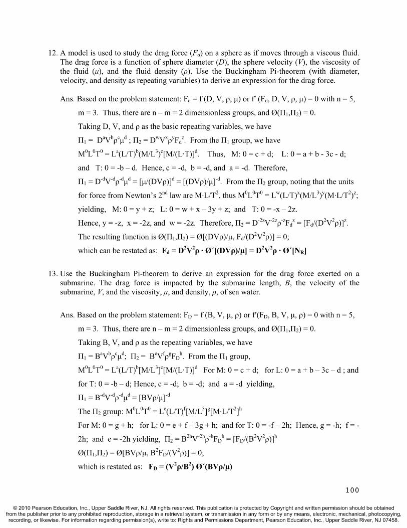
100
12. A model is used to study the drag force (Fd) on a sphere as if moves through a viscous fluid. The drag force is a function of sphere diameter (D), the sphere velocity (V), the viscosity of the fluid ( ), and the fluid density ( ). Use the Buckingham Pi-theorem (with diameter, velocity, and density as repeating variables) to derive an expression for the drag force.
Ans. Based on the problem statement: Fd = f (D, V, , ) or f (Fd, D, V, , ) = 0 with n = 5,
m = 3. Thus, there are n – m = 2 dimensionless groups, and Ø( 1, 2) = 0.
Taking D, V, and as the basic repeating variables, we have
1 = DaVb c d ; 2 = DwVx yFdz. From the 1 group, we have
M0L0T0 = La(L/T)b(M/L3)c[M/(L·T)]d. Thus, M: 0 = c + d; L: 0 = a + b - 3c - d;
and T: 0 = -b – d. Hence, c = -d, b = -d, and a = -d. Therefore,
1 = D-dV-d -d d = [ /(DV )]d = [(DV )/ ]-d. From the 2 group, noting that the units
for force from Newton’s 2nd law are M·L/T2, thus M0L0T0 = Lw(L/T)x(M/L3)y(M·L/T2)z;
yielding, M: 0 = y + z; L: 0 = w + x – 3y + z; and T: 0 = -x – 2z.
Hence, y = -z, x = -2z, and w = -2z. Therefore, 2 = D-2zV-2z -zFdz = [Fd/(D2V2 )]z.
The resulting function is Ø( 1, 2) = Ø[(DV )/ , Fd/(D2V2 )] = 0;
which can be restated as: Fd = D2V2 · Ø´[(DV )/ ] = D2V2 · Ø´[NR]
13. Use the Buckingham Pi-theorem to derive an expression for the drag force exerted on a submarine. The drag force is impacted by the submarine length, B, the velocity of the submarine, V, and the viscosity, , and density, , of sea water.
Ans. Based on the problem statement: FD = f (B, V, , ) or f (FD, B, V, , ) = 0 with n = 5,
m = 3. Thus, there are n – m = 2 dimensionless groups, and Ø( 1, 2) = 0.
Taking B, V, and as the repeating variables, we have
1 = BaVb c d; 2 = BeVf gFDh. From the 1 group,
M0L0T0 = La(L/T)b[M/L3]c[M/(L·T)]d For M: 0 = c + d; for L: 0 = a + b – 3c – d ; and
for T: 0 = -b – d; Hence, c = -d; b = -d; and a = -d yielding,
1 = B-dV-d -d d = [BV / ]-d
The 2 group: M0L0T0 = Le(L/T)f[M/L3]g[M·L/T2]h
For M: 0 = g + h; for L: 0 = e + f – 3g + h; and for T: 0 = -f – 2h; Hence, g = -h; f = -
2h; and e = -2h yielding, 2 = B2hV-2h -hFDh = [FD/(B2V2 )]h
Ø( 1, 2) = Ø[BV / , B2FD/(V2 )] = 0;
which is restated as: FD = (V2 /B2) Ø´(BV / )
© 2010 Pearson Education, Inc., Upper Saddle River, NJ. All rights reserved. This publication is protected by Copyright and written permission should be obtainedfrom the publisher prior to any prohibited reproduction, storage in a retrieval system, or transmission in any form or by any means, electronic, mechanical, photocopying,recording, or likewise. For information regarding permission(s), write to: Rights and Permissions Department, Pearson Education, Inc., Upper Saddle River, NJ 07458.

TEST QUESTIONS & PROBLEMS - CHAPTER #11
Short Answer Questions
1. Define interception and depression storage.Ans. Precipitation caught by buildings, trees, or other vegetation is referred to as
interception. Rainfall that makes it to the ground that does not run off but is trapped in puddles is called depression storage.
2. (T or F) Hydraulics is a science dealing with the properties, distribution, and circulation of the earth's water. Ans. False. This is the definition of hydrology.
3. All of the following are primarily transport phases (rather than storage phases) of the hydrologic cycle except:a) precipitation b) interception c) rivers d) evaporation e) surface runoff Ans. (b) Interception is a storage phase of the hydrologic cycle.
4. (T or F) Watershed boundaries on topographic maps will pass through contour lines in a perpendicular fashion.Ans. True.
5. All of the following are primarily storage phases (as opposed to transport phases) of the hydrologic cycle except:a) evaporation b) interception c) oceans d) aquifer e) depression storage Ans. (a) Evaporation is a transport phase of the hydrologic cycle.
6. What is the difference between a closed and an open hydrologic system? Ans. A closed system does not allow mass transfer across its boundaries.
7. (T or F) A watershed is an example of an open system. Ans. True.
8. Define watershed.Ans. A watershed is a tract of land that contributes (drains) surface water to a stream at a
particular point of interest.
9. All of the following federal agencies are involved in the collection and distribution of hydrologic data except:b) U.S. Geologic Survey b) National Weather Servicec) U.S. Army Corps of Engineers d) Federal Aviation Administration Ans. (d) Federal Aviation Administration – Even though many weather gages are located at airports, they are operated by the National Weather Service.
101
© 2010 Pearson Education, Inc., Upper Saddle River, NJ. All rights reserved. This publication is protected by Copyright and written permission should be obtainedfrom the publisher prior to any prohibited reproduction, storage in a retrieval system, or transmission in any form or by any means, electronic, mechanical, photocopying,recording, or likewise. For information regarding permission(s), write to: Rights and Permissions Department, Pearson Education, Inc., Upper Saddle River, NJ 07458.

10. (T or F) Other terms used for a watershed include catchment and drainage area. Ans. True.
11. Define the term - hydrologic budget. Ans. A hydrologic budget represents a quantitative accounting of the water within a system.
12. The two phases of the hydrologic cycle that are easiest to quantify are: a) evaporation b) interception c) precipitation d) infiltration e) runoffAns. (c) and (e) Precipitation and runoff.
13. What three conditions are necessary for condensation to occur in the atmosphere? Does condensation necessarily produce precipitation? Why or why not? Ans. Three prerequisites are necessary for precipitation to occur; significant atmospheric
moisture, cool temperatures, and condensation nuclei.
14. Three common types of rainfall events are: a) orographic b) cats and dogs c) convective d) plutonic e) cyclonic f) pneumatic Ans. (a), (c), and (e).
15. (T or F) Condensation nuclei are usually particles of ocean salt or combustion by-products. Ans. True.
16. The term defined as the temperature at which water vapor condenses to the liquid state. a) dew point b) saturation point c) absolute humidity d) wet bulb temperatureAns. (a); saturation point is not a temperature but it does occur at the dew point.
17. Lifting and cooling of air laden with water vapor can result in various types of precipitation. Give an example of a type of precipitation that results from thermodynamic lifting. Ans. Either convective precipitation or cyclonic precipitation. .
18. The three common types of rainfall gages are: a) weighing b) tipping bucket c) float and siphon d) capture/release e) displacement Ans. (a), (b), and (c).
19. Identify three methods used to determine average precipitation depth in a watershed.Ans. Arithmetic average, Thiessen polygon, isohyetal, inverse-distance weighting, grid-based, and Krieging. .
20. What is the probability of a 20-year storm event occurring next year? Ans. The probability is 1/20 = 5% chance of occurrence next year or any year.
21. A design storm is characterized in terms of: a) return period b) average rainfall intensity or rainfall depth c) rain duration c) time distribution of rainfall e) spatial distribution of rainfall e) all of the above Ans. All of the above or (e)
102
© 2010 Pearson Education, Inc., Upper Saddle River, NJ. All rights reserved. This publication is protected by Copyright and written permission should be obtainedfrom the publisher prior to any prohibited reproduction, storage in a retrieval system, or transmission in any form or by any means, electronic, mechanical, photocopying,recording, or likewise. For information regarding permission(s), write to: Rights and Permissions Department, Pearson Education, Inc., Upper Saddle River, NJ 07458.

22. Define the term interception. Ans. Rain caught by the leaves & stems of vegetation or by manmade structures like rooftops.
23. (T or F) A stage-discharge relationship at a given stream location is known as a rating curve.Ans. True
24. The demands that need to be satisfied by rainfall before runoff is produced include all of the following except: d) interception b) depression storage c) soil moisture replenishment d) interflow Ans. Interflow contributes to runoff, so (d) is the answer.
25. Define the term depression storage. Ans. Depression storage is rainfall that is retained on the ground as puddles or small isolated wetlands.
26. (T or F) The portion of water which percolates downward through the soil to the ground water table and eventually arrives in a nearby stream is called interflow. Ans. False. This is groundwater flow. Interflow is water that makes its way to the stream through the soil above the ground water table.
27. What is the difference between a one-hour and a two-hour unit hydrograph? (Hint: the answer is not one hour!)Ans. A 1-hour unit hydrograph is produced by one inch of runoff that occurs over a one hour time period, and a 2-hour unit hydrograph is produced by one inch of runoff that occurs over a two hour time period.
28. Sketch a typical hydrograph and label the base flow and volume of direct surface runoff. Ans.
29. (T or F) A unit hydrograph is a plot of flow over time at a stream location that results from one inch of rainfall over a specified duration. Ans. False. One inch of runoff, not one inch a rainfall.
30. The “unit” in the term unit hydrograph (UH) refers toa) one hour storm b) one inch of rainfall c) one inch of runoff d) one hour time increment Ans. (c); one inch of runoff.
103
© 2010 Pearson Education, Inc., Upper Saddle River, NJ. All rights reserved. This publication is protected by Copyright and written permission should be obtainedfrom the publisher prior to any prohibited reproduction, storage in a retrieval system, or transmission in any form or by any means, electronic, mechanical, photocopying,recording, or likewise. For information regarding permission(s), write to: Rights and Permissions Department, Pearson Education, Inc., Upper Saddle River, NJ 07458.

31. What two principles are assumed in using a unit hydrograph to predict a watershed’s response to a future (design) rainfall event? Ans. Linearity and superposition.
32. (T or F) A watershed has an infinite number of unit hydrographs. Ans. True (i.e., 30-min, unit hydrograph, 1-hr unit hydrograph, 2-hr unit hydrograph, etc.).
33. Define the term “hydraulic length.” Ans. It is the length of the longest flow path in the watershed (from the design point to the hydrologically most remote point in the watershed located on the drainage divide).
34. Which two watershed characteristics are required to determine the SCS curve number (CN)? a) hydraulic length b) slope c) hydrologic soil group d) land use e) drainage areaAns. (c) and (d).
35. (T or F) Synthetic unit hydrographs are useful design tools since most small watersheds do not have gages. Ans. True.
36. Define “synthetic” in the term “synthetic unit hydrograph.”Ans. A unit hydrograph that is developed using existing stream gages and transposing the information to hydrologically similar watersheds that lack gage information.
37. (T or F) The theoretical range of the SCS curve number (CN) is 40 to 100. Ans. False; it is 0 to 100.
38. Define the term “rainfall excess.” Ans. That part of the rainfall that becomes runoff, sometimes called direct runoff or just runoff.
39. Name the three phases (types) of flow that are likely to occur as water travels through the hydraulic length of a watershed.Ans. Sheet flow, shallow concentrated flow, and channel flow.
40. According to SCS, the time of concentration is composed of which of the following times? a) sheet flow b) shallow concentrated c) channel d) a and c only e) a, b, and cAns. (e).
41. (T or F) The SCS time-to-peak is the elapsed time from the beginning of the effective (runoff-producing) rainfall to the time when the peak discharge occurs.Ans. True.
42. Define the term “time of concentration.” Ans. The time it takes runoff to reach the design point from the hydrologically most remote point in the watershed.
104
© 2010 Pearson Education, Inc., Upper Saddle River, NJ. All rights reserved. This publication is protected by Copyright and written permission should be obtainedfrom the publisher prior to any prohibited reproduction, storage in a retrieval system, or transmission in any form or by any means, electronic, mechanical, photocopying,recording, or likewise. For information regarding permission(s), write to: Rights and Permissions Department, Pearson Education, Inc., Upper Saddle River, NJ 07458.

43. Show all steps in the proof of the mass balance equation in going from dS/dt = I – O to the following: Ii + Ij + (2S/ t – O)i = (2S/ t + O)jAns. Starting with dS/dt = I – O and going to discrete time steps, we have:
S/ t = Iavg – Oavg which can be restated as: (Sj – Si)/ t = (Ii + Ij)/2 - (Oi + Oj)/2 Finally, these terms can be rearranged as: Ii + Ij + (2S/ t – O)i = (2S/ t + O)j
44. (T or F) The orifice and mass balance equations are often used in elevation-outflow determinations for stormwater management pond outlet devices. Ans. False – the orifice and weir equations.
45. To perform reservoir (storage) routing computations, all of the following are required excepta) inflow hydrograph b) outflow hydrograph c) elevation-storage relationship d) elevation-outflow relationship e) routing time step Ans. (b).
46. Define the term “storage routing.” Ans. The process of evaluating the changes in a storm hydrograph as it passes through a pond or reservoir. In other words, an outflow hydrograph is developed using the inflow hydrograph, storage characteristics of the site, and the hydraulic properties outlet device.
47. (T or F) The area in between the inflow and outflow hydrographs represents the storage of water in a reservoir or pond. Ans. True.
48. Which parameter is not needed in solving for peak flow using the rational equation?a) hydrologic soil group b) return interval c) time of concentration d) drainage area Ans. (a). The hydrologic soil group is needed in the SCS procedure.
49. (T or F) Time of concentration does not equal the storm duration in the rational method. Ans. False.
50. Define the term “pavement encroachment criteria.” Ans. The limiting spread of water in the street before a drainage inlet is needed. .
51. Give three locations that require the placement of a drainage inlet.Ans. In all sumps, when the curb height is exceeded, along the curb when the pavement encroachment criteria is exceeded, upgrade of all bridges, and prior to an intersection.
52. Give three locations that require the placement of a manhole. Ans. Manholes are needed at pipe junctions, changes of grade, and changes of alignment.
53. (T or F) Pipe slopes match overlying ground slopes when possible to minimize excavation. Ans. True.
54. Why are pipe sizes not reduced downstream when increased slopes provide adequate flow? Ans. Clogging is a concern.
105
© 2010 Pearson Education, Inc., Upper Saddle River, NJ. All rights reserved. This publication is protected by Copyright and written permission should be obtainedfrom the publisher prior to any prohibited reproduction, storage in a retrieval system, or transmission in any form or by any means, electronic, mechanical, photocopying,recording, or likewise. For information regarding permission(s), write to: Rights and Permissions Department, Pearson Education, Inc., Upper Saddle River, NJ 07458.
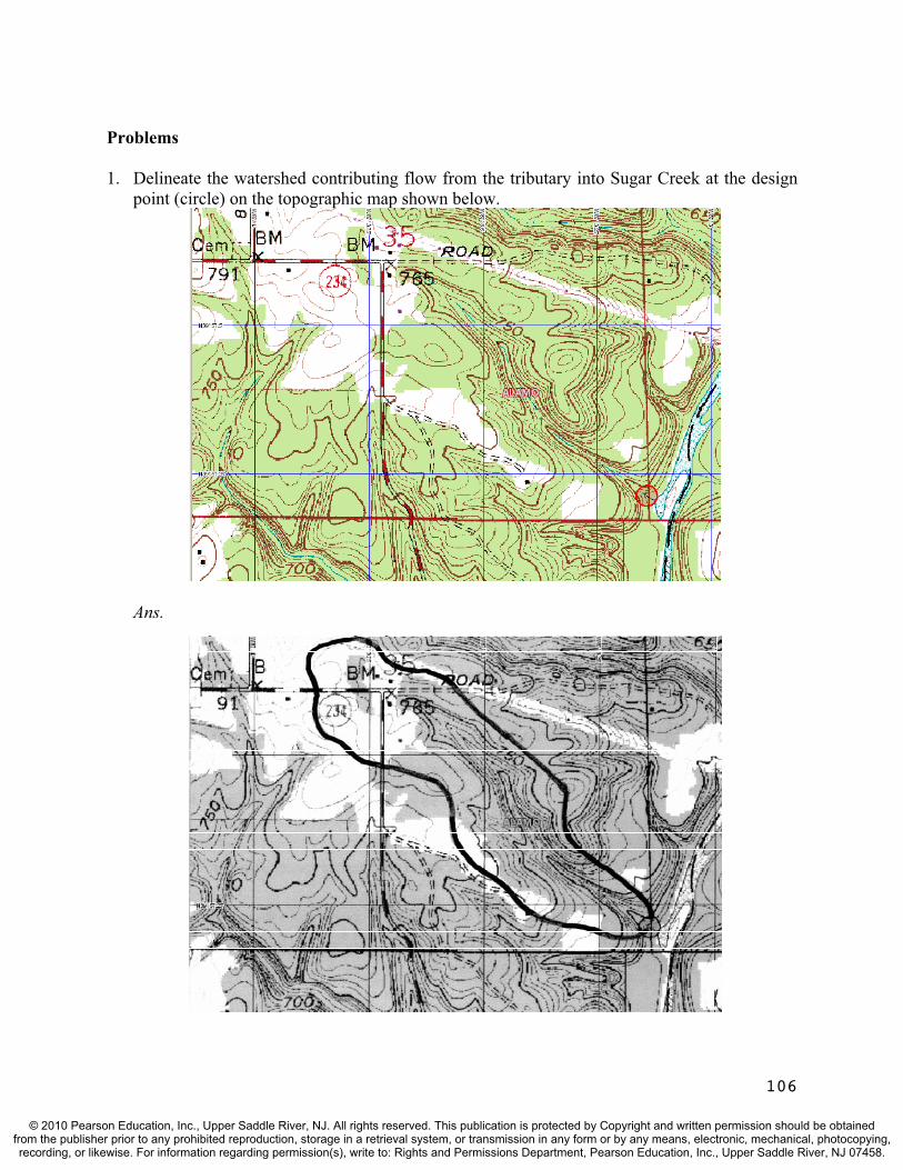
Problems
1. Delineate the watershed contributing flow from the tributary into Sugar Creek at the design point (circle) on the topographic map shown below.
Ans.
106
© 2010 Pearson Education, Inc., Upper Saddle River, NJ. All rights reserved. This publication is protected by Copyright and written permission should be obtainedfrom the publisher prior to any prohibited reproduction, storage in a retrieval system, or transmission in any form or by any means, electronic, mechanical, photocopying,recording, or likewise. For information regarding permission(s), write to: Rights and Permissions Department, Pearson Education, Inc., Upper Saddle River, NJ 07458.
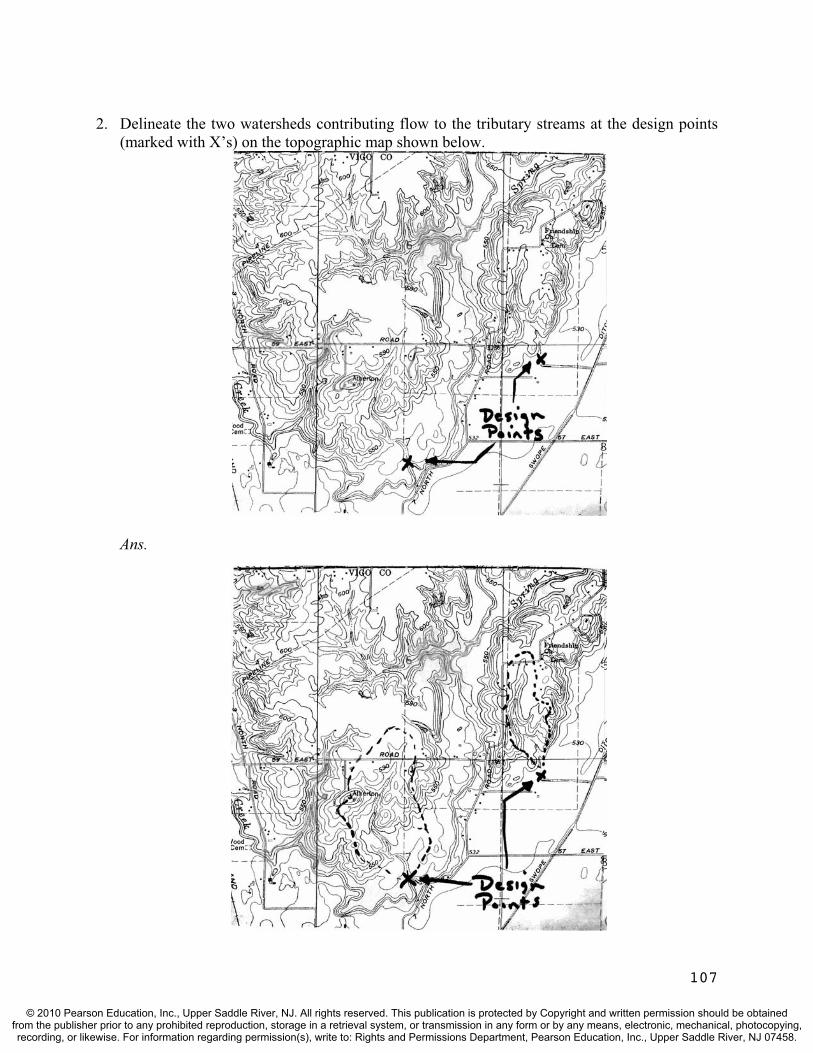
2. Delineate the two watersheds contributing flow to the tributary streams at the design points (marked with X’s) on the topographic map shown below.
Ans.
107
© 2010 Pearson Education, Inc., Upper Saddle River, NJ. All rights reserved. This publication is protected by Copyright and written permission should be obtainedfrom the publisher prior to any prohibited reproduction, storage in a retrieval system, or transmission in any form or by any means, electronic, mechanical, photocopying,recording, or likewise. For information regarding permission(s), write to: Rights and Permissions Department, Pearson Education, Inc., Upper Saddle River, NJ 07458.
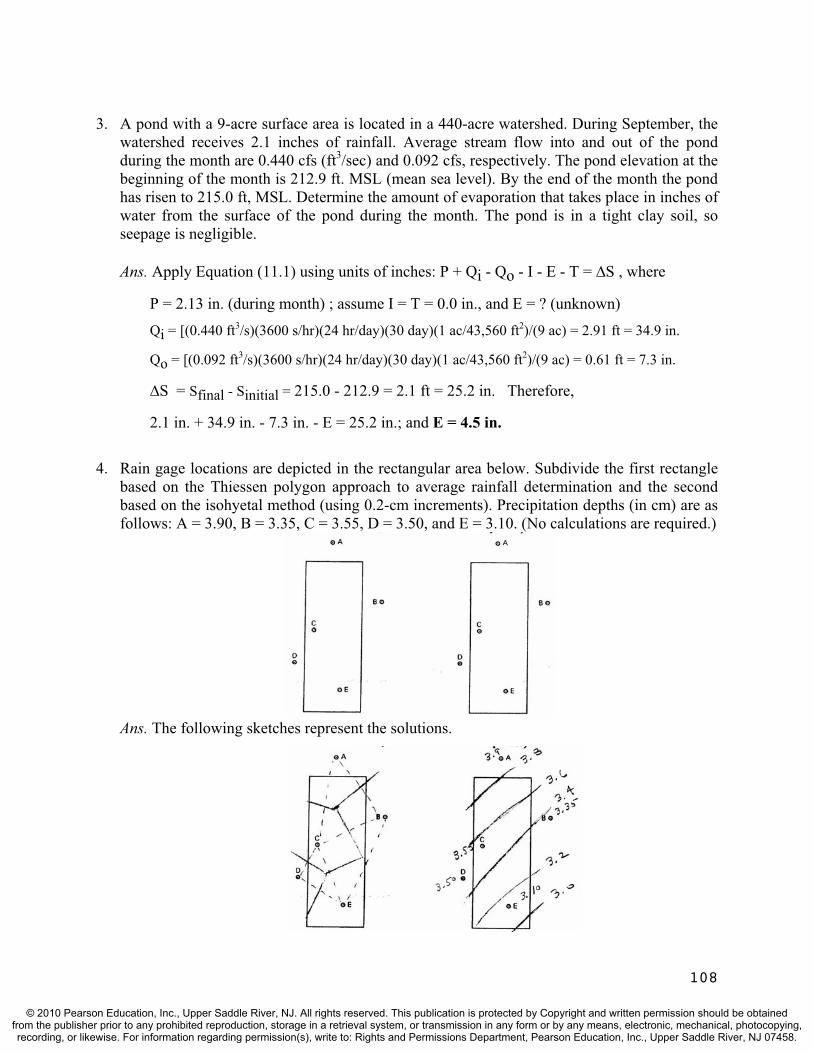
3. A pond with a 9-acre surface area is located in a 440-acre watershed. During September, the watershed receives 2.1 inches of rainfall. Average stream flow into and out of the pond during the month are 0.440 cfs (ft3/sec) and 0.092 cfs, respectively. The pond elevation at the beginning of the month is 212.9 ft. MSL (mean sea level). By the end of the month the pond has risen to 215.0 ft, MSL. Determine the amount of evaporation that takes place in inches of water from the surface of the pond during the month. The pond is in a tight clay soil, so seepage is negligible.
Ans. Apply Equation (11.1) using units of inches: P + Qi - Qo - I - E - T = S , where
P = 2.13 in. (during month) ; assume I = T = 0.0 in., and E = ? (unknown)
Qi = [(0.440 ft3/s)(3600 s/hr)(24 hr/day)(30 day)(1 ac/43,560 ft2)/(9 ac) = 2.91 ft = 34.9 in.
Qo = [(0.092 ft3/s)(3600 s/hr)(24 hr/day)(30 day)(1 ac/43,560 ft2)/(9 ac) = 0.61 ft = 7.3 in.
S = Sfinal - Sinitial = 215.0 - 212.9 = 2.1 ft = 25.2 in. Therefore,
2.1 in. + 34.9 in. - 7.3 in. - E = 25.2 in.; and E = 4.5 in.
4. Rain gage locations are depicted in the rectangular area below. Subdivide the first rectangle based on the Thiessen polygon approach to average rainfall determination and the second based on the isohyetal method (using 0.2-cm increments). Precipitation depths (in cm) are as follows: A = 3.90, B = 3.35, C = 3.55, D = 3.50, and E = 3.10. (No calculations are required.)
Ans. The following sketches represent the solutions.
108
© 2010 Pearson Education, Inc., Upper Saddle River, NJ. All rights reserved. This publication is protected by Copyright and written permission should be obtainedfrom the publisher prior to any prohibited reproduction, storage in a retrieval system, or transmission in any form or by any means, electronic, mechanical, photocopying,recording, or likewise. For information regarding permission(s), write to: Rights and Permissions Department, Pearson Education, Inc., Upper Saddle River, NJ 07458.
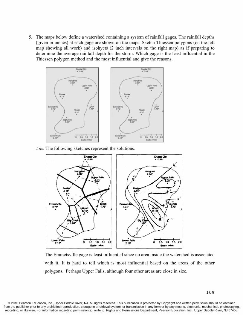
5. The maps below define a watershed containing a system of rainfall gages. The rainfall depths (given in inches) at each gage are shown on the maps. Sketch Thiessen polygons (on the left map showing all work) and isohyets (2 inch intervals on the right map) as if preparing to determine the average rainfall depth for the storm. Which gage is the least influential in the Thiessen polygon method and the most influential and give the reasons.
Ans. The following sketches represent the solutions.
The Emmetsville gage is least influential since no area inside the watershed is associated
with it. It is hard to tell which is most influential based on the areas of the other
polygons. Perhaps Upper Falls, although four other areas are close in size.
109
© 2010 Pearson Education, Inc., Upper Saddle River, NJ. All rights reserved. This publication is protected by Copyright and written permission should be obtainedfrom the publisher prior to any prohibited reproduction, storage in a retrieval system, or transmission in any form or by any means, electronic, mechanical, photocopying,recording, or likewise. For information regarding permission(s), write to: Rights and Permissions Department, Pearson Education, Inc., Upper Saddle River, NJ 07458.
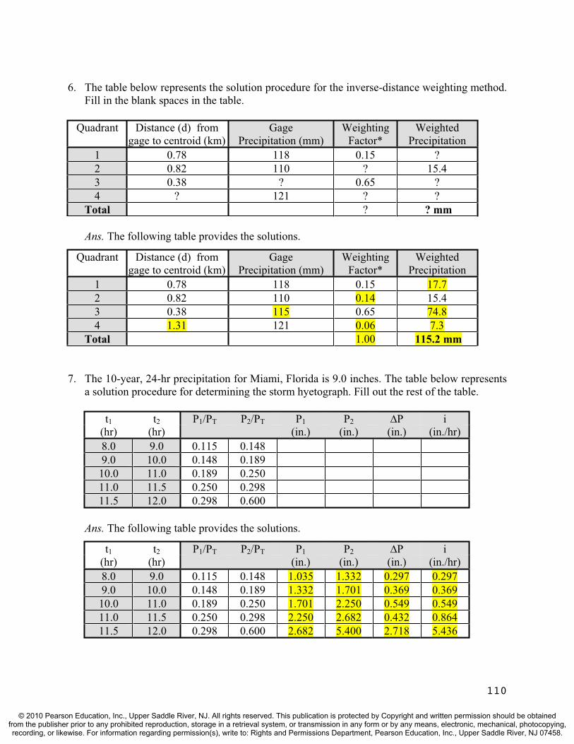
6. The table below represents the solution procedure for the inverse-distance weighting method. Fill in the blank spaces in the table.
Quadrant Distance (d) from gage to centroid (km)
GagePrecipitation (mm)
Weighting Factor*
WeightedPrecipitation
1 0.78 118 0.15 ?2 0.82 110 ? 15.43 0.38 ? 0.65 ?4 ? 121 ? ?
Total ? ? mm
Ans. The following table provides the solutions.
Quadrant Distance (d) from gage to centroid (km)
GagePrecipitation (mm)
Weighting Factor*
WeightedPrecipitation
1 0.78 118 0.15 17.72 0.82 110 0.14 15.43 0.38 115 0.65 74.84 1.31 121 0.06 7.3
Total 1.00 115.2 mm
7. The 10-year, 24-hr precipitation for Miami, Florida is 9.0 inches. The table below represents a solution procedure for determining the storm hyetograph. Fill out the rest of the table.
t1 t2 P1/PT P2/PT P1 P2 P i(hr) (hr) (in.) (in.) (in.) (in./hr)8.0 9.0 0.115 0.1489.0 10.0 0.148 0.18910.0 11.0 0.189 0.25011.0 11.5 0.250 0.29811.5 12.0 0.298 0.600
Ans. The following table provides the solutions.
t1 t2 P1/PT P2/PT P1 P2 P i(hr) (hr) (in.) (in.) (in.) (in./hr)8.0 9.0 0.115 0.148 1.035 1.332 0.297 0.2979.0 10.0 0.148 0.189 1.332 1.701 0.369 0.36910.0 11.0 0.189 0.250 1.701 2.250 0.549 0.54911.0 11.5 0.250 0.298 2.250 2.682 0.432 0.86411.5 12.0 0.298 0.600 2.682 5.400 2.718 5.436
110
© 2010 Pearson Education, Inc., Upper Saddle River, NJ. All rights reserved. This publication is protected by Copyright and written permission should be obtainedfrom the publisher prior to any prohibited reproduction, storage in a retrieval system, or transmission in any form or by any means, electronic, mechanical, photocopying,recording, or likewise. For information regarding permission(s), write to: Rights and Permissions Department, Pearson Education, Inc., Upper Saddle River, NJ 07458.

8. A current meter is used to obtain velocity measurements in a rectangular channel. Iso-velocity lines (in m/sec) are drawn using the velocity measurements and are depicted in the channel cross-section below. Determine the discharge in m3/sec? (Note: The greatest point velocity is in the middle of the 4 m/sec iso-line and is 5 m/sec.)
Ans. Determine the area between iso-velocity lines and multiply the area by the average
velocity in the interval. The average velocity is usually the average of the bounding iso-
velocity lines, except for the area bounded by the 4 m/sec iso-line. In this case, the
average of 4 m/sec and 5 m/sec is used since 5 m/sec is the largest point velocity. Thus;
Q = (Ai)(Vi,avg) = [(22 m2)(1.0 m/s) + (14 m2)(3.0 m/s) + (6 m2)(4.5 m/s)]
Q = 4.5 m3/sec
9. The stream flow data shown below were recorded at a river gage during a flood event. If the watershed is 900 km2, compute the unit hydrograph. Assume the base flow to be linear from 120 m3/s (at t = 6 hrs) to 200 m3/s (at t = 54 hours).
Stream Ans. Base Direct Unit Hours Hour Flow Flow Runoff Hydrograph After
(m3/s) (m3/s) (m3/s) (m3/s) Start6 120 120 0 0 0
12 250 130 120 30 6 18 400 140 260 65 12 24 550 150 400 100 18 30 520 160 360 90 24 36 470 170 300 75 30 42 340 180 160 40 36 48 254 190 64 16 42 54 200 200 0 0 48 60 190 190 0 0 54
Sum 1664.0 Runoff 4.0 cm
111
© 2010 Pearson Education, Inc., Upper Saddle River, NJ. All rights reserved. This publication is protected by Copyright and written permission should be obtainedfrom the publisher prior to any prohibited reproduction, storage in a retrieval system, or transmission in any form or by any means, electronic, mechanical, photocopying,recording, or likewise. For information regarding permission(s), write to: Rights and Permissions Department, Pearson Education, Inc., Upper Saddle River, NJ 07458.
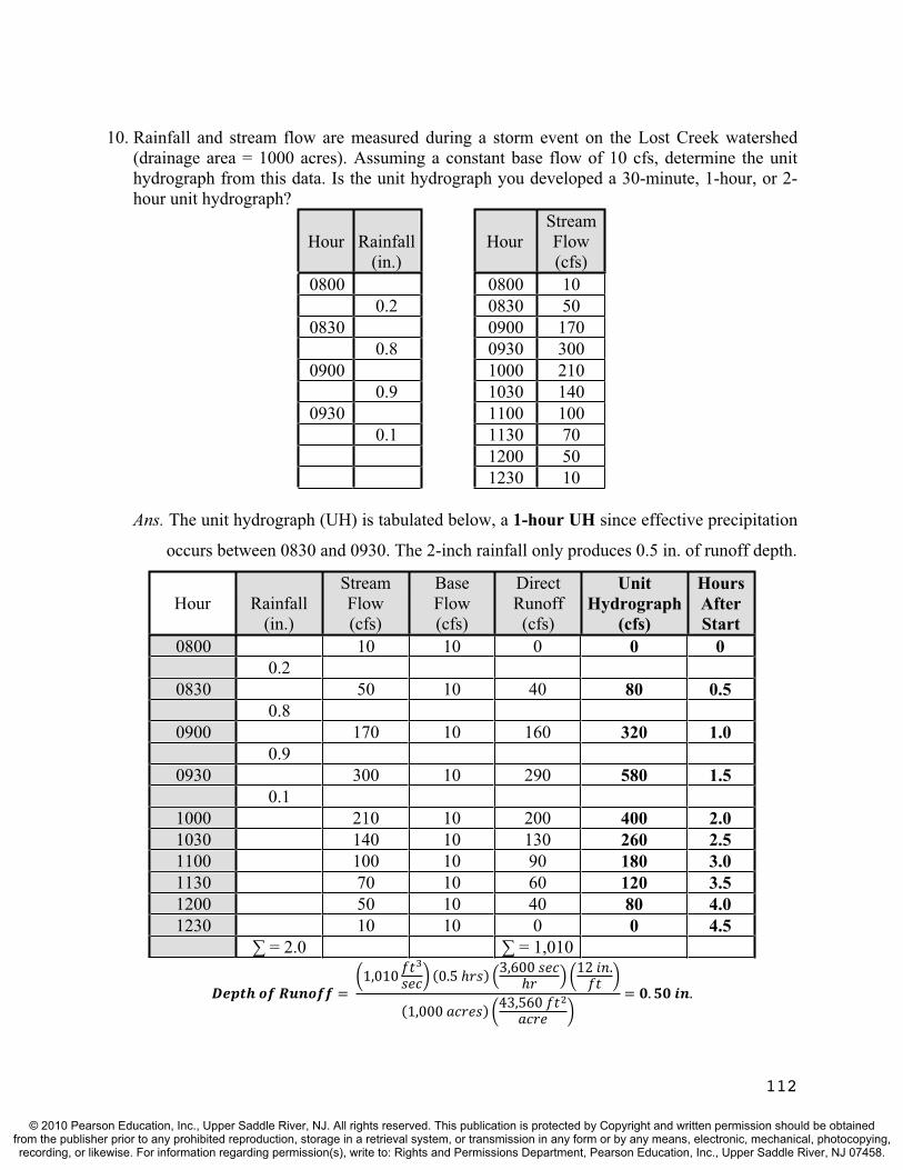
10. Rainfall and stream flow are measured during a storm event on the Lost Creek watershed (drainage area = 1000 acres). Assuming a constant base flow of 10 cfs, determine the unit hydrograph from this data. Is the unit hydrograph you developed a 30-minute, 1-hour, or 2-hour unit hydrograph?
Hour Rainfall(in.)
HourStreamFlow(cfs)
0800 0800 100.2 0830 50
0830 0900 1700.8 0930 300
0900 1000 2100.9 1030 140
0930 1100 1000.1 1130 70
1200 501230 10
Ans. The unit hydrograph (UH) is tabulated below, a 1-hour UH since effective precipitation
occurs between 0830 and 0930. The 2-inch rainfall only produces 0.5 in. of runoff depth.
Hour Rainfall (in.)
Stream Flow(cfs)
BaseFlow(cfs)
DirectRunoff
(cfs)
UnitHydrograph
(cfs)
HoursAfter Start
0800 10 10 0 0 00.2
0830 50 10 40 80 0.50.8
0900 170 10 160 320 1.00.9
0930 300 10 290 580 1.50.1
1000 210 10 200 400 2.01030 140 10 130 260 2.51100 100 10 90 180 3.01130 70 10 60 120 3.51200 50 10 40 80 4.01230 10 10 0 0 4.5
= 2.0 = 1,010
112
© 2010 Pearson Education, Inc., Upper Saddle River, NJ. All rights reserved. This publication is protected by Copyright and written permission should be obtainedfrom the publisher prior to any prohibited reproduction, storage in a retrieval system, or transmission in any form or by any means, electronic, mechanical, photocopying,recording, or likewise. For information regarding permission(s), write to: Rights and Permissions Department, Pearson Education, Inc., Upper Saddle River, NJ 07458.

11. A 2-hour unit hydrograph for the Wright Water Creek watershed is given below. Determine the watershed’s response to a hypothetical design storm in which 3 inches of rain fell in the first 2 hours and 1.5 inches in the next 2 hours. Assume runoff depth is two-thirds of the rainfall depth and the base flow is 10 cfs.
Time (hrs) 0 1 2 3 4 5 6 7 8Q (cfs) 0 30 80 120 100 70 40 20 0
Ans. Multiplying the rainfall depths by (2/3) yields 2.0 inches of runoff in the 1st two-hour
period and 1.0 inches of runoff in the 2nd two-hour period. Thus, multiplying the unit
hydrograph by runoff depths and lagging the second hour of runoff by 2 hours yields:
Unit 2×UH 1×UH Base StreamHour Hyd. Flow Flow
(cfs) (cfs) (cfs) (cfs) (cfs) 0 0 0 10 101 30 60 10 702 80 160 0 10 1703 120 240 30 10 2804 100 200 80 10 2905 70 140 120 10 2706 40 80 100 10 1907 20 40 70 10 1208 0 0 40 10 509 0 0 20 10 3010 0 0 0 10 10
12. A 4-hour unit hydrograph is given below for the Honey Creek watershed. Determine the expected peak flow in the watershed for a design storm in which 8 cm of rain falls over an 8 hour period. Assume the effective precipitation (direct runoff) constitutes one half of the precipitation amount and the rain is uniform over time. Base flow is uniform at 50 m3/sec.
Time (hrs)
UnitHydrograph
(m3/sec)
Time (hrs)
UnitHydrograph
(m3/sec)0 0 10 8002 400 12 5004 1000 14 3506 1400 16 2008 1200 18 50
113
© 2010 Pearson Education, Inc., Upper Saddle River, NJ. All rights reserved. This publication is protected by Copyright and written permission should be obtainedfrom the publisher prior to any prohibited reproduction, storage in a retrieval system, or transmission in any form or by any means, electronic, mechanical, photocopying,recording, or likewise. For information regarding permission(s), write to: Rights and Permissions Department, Pearson Education, Inc., Upper Saddle River, NJ 07458.

Ans. Based on the problem statement, we have 4 cm of runoff that is distributed uniformly
over two, 4-hour periods (in order to use the 4-hour unit hydrograph) which yields:
Unit 2×UH 2×UH Base StreamHour Hyd. Flow Flow
(cms) (cms) (cms) (cms) (cms) 0 0 0 50 502 400 800 50 8504 1000 2000 0 50 20506 1400 2800 800 50 36508 1200 2400 2000 50 4450 Peak Q
10 800 1600 2800 50 445012 500 1000 2400 50 3450
13. Lost Creek’s 1-hour unit hydrograph (UH1) at Chamberlain Avenue is displayed below. Use this information to determine the 3-hour unit hydrograph (UH3). Also determine the depth of runoff for the UH3 if the watershed is 228 acres.
Time (hrs) 0 0.5 1.0 1.5 2.0 2.5 3.0 3.5 4.0 4.5Q (cfs) 0 9 30 90 120 90 60 45 15 0
Ans. A UH1 is produced by one inch of runoff over 1 hour. A UH3 is produced by one inch of
runoff over 3 hours, and thus 0.33 in. of runoff each hour of the 3 hour storm. Therefore:
UH1 0.33×UH1 0.33×UH1 0.33×UH1 UH3Hour(cfs) (cfs) (cfs) (cfs) (cfs)
0.0 0 0 00.5 30 10 101.0 75 25 0 251.5 120 40 10 502.0 90 30 25 0 552.5 60 20 40 10 703.0 45 15 30 25 703.5 15 5 20 40 654.0 0 0 15 30 454.5 0 5 20 255.0 0 0 15 155.5 0 0 5 5
By definition, the runoff depth for a unit hydrograph in the BG system is 1 inch.
114
© 2010 Pearson Education, Inc., Upper Saddle River, NJ. All rights reserved. This publication is protected by Copyright and written permission should be obtainedfrom the publisher prior to any prohibited reproduction, storage in a retrieval system, or transmission in any form or by any means, electronic, mechanical, photocopying,recording, or likewise. For information regarding permission(s), write to: Rights and Permissions Department, Pearson Education, Inc., Upper Saddle River, NJ 07458.

14. A 200 hectare watershed is slated for commercial and business development. Currently the watershed is open space (good condition) with 40% B-soils and 60% D-soils. Determine the increase in runoff depth from a 10 cm rainfall event due to developing the watershed.
Ans. Based on Table 11.4, CN = 61 for open space - B soils, CN = 80 for open space - D
soils, CN = 92 for the commercial area - B soils, and CN = 95 for the commercial area -
- D soils. The pre-development and post-development, area-weighted composite curve
numbers for the whole watershed are:
CN = [(80 hec)(61) + (120 hec)(80)]/200 hec = 72.4 (pre-development)
CN = [(80 hec)(92) + (120 hec)(95)]/200 hec = 93.8 (post-development)
For a 10 cm (3.94 in.) storm, use Eq’ns 11.4 and 11.3 (or Figure 11.18):
Pre-development: S = {1000 – 10(72.4)}/72.4 = 3.81 in.;
R = [P – 0.2(S)]2/[P + 0.8(S)] = [3.94 – 0.2(3.81)]2/[3.94 + 0.8(3.81)] = 1.45 in.
Post-development: S = {1000 – 10(93.8)}/93.8 = 0.66 in.;
R = [P – 0.2(S)]2/[P + 0.8(S)] = [3.94 – 0.2(0.66)]2/[3.94 + 0.8(0.66)] = 3.25 in.
Thus the increase in runoff depth is (3.25 -1.45) = 1.80 in. (4.57 cm)
15. A development is being planned for a large tract of land in Albemarle County, Virginia. The development will encompass a 250-acre watershed with a hydraulic length of 4500 feet. The predominant land use is horse pasture (C soils) with an average land slope of 8%. The land use in the watershed is scheduled to change over the next ten years to single family residential (1/2-acre lots). Determine the SCS peak discharge after development.
Ans. The time-to-peak requires the time of concentration. Applying Equation (11.9)
Tc = [L0.8 (S+1)0.7]/(1140 Y0.5)
where; S = (1000/CN) - 10 = (1000/80) - 10 = 2.50 in.
where the curve number is found in Table 11.4 (residential, ½-acre lots, C soils).
Substituting the hydraulic length and watershed slope into Equation (11.9) yields
Tc = [(4500)0.8 (2.50+1)0.7]/(1140 (8)0.5) = 0.624 hours (37.4 minutes)
By applying Equation (11.13), an estimate of the time-to-peak is
Tp = 0.67 Tc = 0.67(0.624) = 0.418 hours (25.1 minutes)
The peak discharge for the watershed is calculated from Equation (11.14) as
qp = (Kp A)/Tp = 484 [250 acres (1 sq.mi./640 acres)]/0.418 hrs = 452 cfs
115
© 2010 Pearson Education, Inc., Upper Saddle River, NJ. All rights reserved. This publication is protected by Copyright and written permission should be obtainedfrom the publisher prior to any prohibited reproduction, storage in a retrieval system, or transmission in any form or by any means, electronic, mechanical, photocopying,recording, or likewise. For information regarding permission(s), write to: Rights and Permissions Department, Pearson Education, Inc., Upper Saddle River, NJ 07458.

16. G en the following 2S/ t + O vs. Outflow (O) graph, compute the outflow hydrograph from the reservoir using the design storm (inflow hydrograph) provided. Identify the peak inflow, peak outflow, and the storage volume required to reduce the peak by this amount.
iv
0
5
10
15
20
25
30
35
0 50 100 150 200
Outflo
w(O),(m
3 /sec)
(2S/ t)+O, (m3/sec)
2S/ t + O vs. Outflow (O)
The reservoir inflow hydrograph is given below (in the first two columns).
Time Inflow (Ii) Inflow (Ij) (2S/ t) O (2S/ t)+O Outflow, O(min) (m3/sec) (m3/sec) (m3/sec) (m3/sec) (m3/sec)
0 2 13 0 220 13 37 9 15 340 37 55 37 59 1160 55 47 81 129 2480 47 31 117 183 33
100 31 22 125 195 35120 22 17 114 178 32140 17 8 97 153 28160 8 5 76 122 23180 5 55 89 17
Ans. The storage routing table is shown above (the last four columns need to filled out). The
peak inflow is 55 m3/sec and the outflow peak is 35 m3/sec. To determine the storage,
note that 2S/ t + O = 195 m3/sec at the time that the peak discharge occurs in the
routing table. Subracting; (2S/ t + O) – O = 2S/ t; 195 – 35 = 160 m3/sec = 2S/ t.
Since t = 20 min. 2S/ t = 160 m3/sec; 2S/(1200 sec) = 160 m3/sec; Speak = 96,000 m3.
116
© 2010 Pearson Education, Inc., Upper Saddle River, NJ. All rights reserved. This publication is protected by Copyright and written permission should be obtainedfrom the publisher prior to any prohibited reproduction, storage in a retrieval system, or transmission in any form or by any means, electronic, mechanical, photocopying,recording, or likewise. For information regarding permission(s), write to: Rights and Permissions Department, Pearson Education, Inc., Upper Saddle River, NJ 07458.
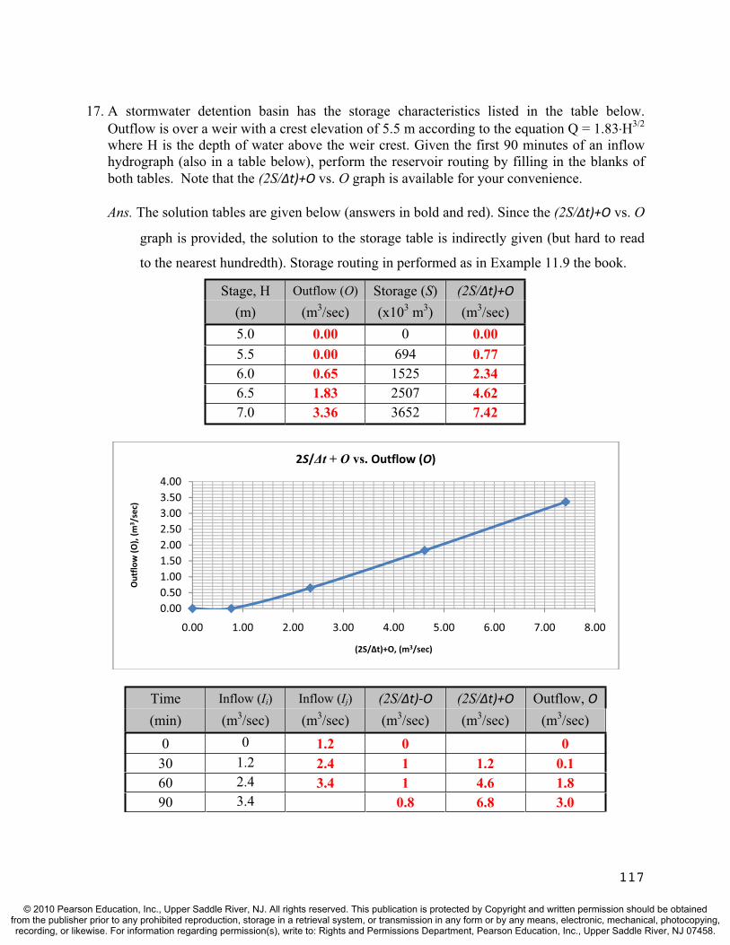
17. A stormwater detention basin has the storage characteristics listed in the table below. Outflow is over a weir with a crest elevation of 5.5 m according to the equation Q = 1.83 H3/2
where H is the depth of water above the weir crest. Given the first 90 minutes of an inflow hydrograph (also in a table below), perform the reservoir routing by filling in the blanks of both tables. Note that the (2S/ t)+O vs. O graph is available for your convenience.
Ans. The solution tables are given below (answers in bold and red). Since the (2S/ t)+O vs. O
graph is provided, the solution to the storage table is indirectly given (but hard to read
to the nearest hundredth). Storage routing in performed as in Example 11.9 the book.
Stage, H Outflow (O) Storage (S) (2S/ t)+O
(m) (m3/sec) (x103 m3) (m3/sec)5.0 0.00 0 0.005.5 0.00 694 0.776.0 0.65 1525 2.346.5 1.83 2507 4.627.0 3.36 3652 7.42
0.000.501.001.502.002.503.003.504.00
0.00 1.00 2.00 3.00 4.00 5.00 6.00 7.00 8.00
Outflo
w(O),(m
3 /sec)
(2S/ t)+O, (m3/sec)
2S/ t + O vs. Outflow (O)
Time Inflow (Ii) Inflow (Ij) (2S/ t) O (2S/ t)+O Outflow, O(min) (m3/sec) (m3/sec) (m3/sec) (m3/sec) (m3/sec)
0 0 1.2 0 030 1.2 2.4 1 1.2 0.160 2.4 3.4 1 4.6 1.890 3.4 0.8 6.8 3.0
117
© 2010 Pearson Education, Inc., Upper Saddle River, NJ. All rights reserved. This publication is protected by Copyright and written permission should be obtainedfrom the publisher prior to any prohibited reproduction, storage in a retrieval system, or transmission in any form or by any means, electronic, mechanical, photocopying,recording, or likewise. For information regarding permission(s), write to: Rights and Permissions Department, Pearson Education, Inc., Upper Saddle River, NJ 07458.

18. The [2S/ t + O] vs. Outflow table for a flood control reservoir is shown below. In addition, a storage routing table is provided for a flood that occurs and passes through the reservoir. Fill in the blanks of both tables and determine the peak outflow and the peak elevation that occurred during the flood.
Ans. The blanks in the [2S/ t + O] vs. Outflow table and the storage routing table are filled
in and given below (in bold and red). Storage routing is performed as in Example 11.9
the book. The time increment is t = 12 hours = 43,200 sec based on the routing table.
Ouflows in the routing table need to be interpolated from the [2S/ t + O] vs. Outflow
table since no graph is provided. The peak outflow is 262 cfs. Taking this outflow to
the [2S/ t + O] vs. Outflow table and interpolating yields a peak elevation of
approximately 883.5 ft, MSL
Elevation Outflow (O) Storage (S) 2S/ t (2S/ t)+O (ft, MSL) (cfs) (acre-ft) (cfs) (cfs)
865 0 0 0 0870 20 140 282 302
875 50 280 565 615 880 130 660 1331 1461 885 320 1220 2460 2780
Day/Time Inflow (Ii) Inflow (Ij) (2S/ t)-O (2S/ t)+O Outflow, O (cfs) (cfs) (cfs) (cfs) (cfs)
1 - noon 2 58 0 2
midnight 58 118 52 60 4
2 - noon 118 212 198 228 15 midnight 212 312 444 528 42 3 - noon 312 466 802 968 83 midnight 466 366 1286 1580 147 4 - noon 366 302 1668 2118 225 midnight 302 248 1824 2336 256 5 - noon 248 202 1850 2374 262 midnight 202 122 1798 2300 251 6 - noon 122 68 1672 2122 225
118
© 2010 Pearson Education, Inc., Upper Saddle River, NJ. All rights reserved. This publication is protected by Copyright and written permission should be obtainedfrom the publisher prior to any prohibited reproduction, storage in a retrieval system, or transmission in any form or by any means, electronic, mechanical, photocopying,recording, or likewise. For information regarding permission(s), write to: Rights and Permissions Department, Pearson Education, Inc., Upper Saddle River, NJ 07458.
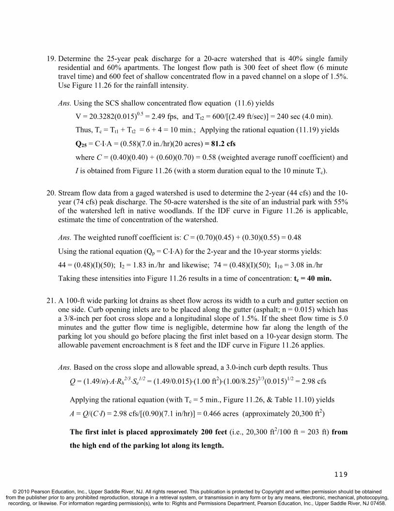
19. Determine the 25-year peak discharge for a 20-acre watershed that is 40% single family residential and 60% apartments. The longest flow path is 300 feet of sheet flow (6 minute travel time) and 600 feet of shallow concentrated flow in a paved channel on a slope of 1.5%. Use Figure 11.26 for the rainfall intensity.
Ans. Using the SCS shallow concentrated flow equation (11.6) yields
V = 20.3282(0.015)0.5 = 2.49 fps, and Tt2 = 600/[(2.49 ft/sec)] = 240 sec (4.0 min).
Thus, Tc = Tt1 + Tt2 = 6 + 4 = 10 min.; Applying the rational equation (11.19) yields
Q25 = C I A = (0.58)(7.0 in./hr)(20 acres) = 81.2 cfs
where C = (0.40)(0.40) + (0.60)(0.70) = 0.58 (weighted average runoff coefficient) and
I is obtained from Figure 11.26 (with a storm duration equal to the 10 minute Tc).
20. Stream flow data from a gaged watershed is used to determine the 2-year (44 cfs) and the 10-year (74 cfs) peak discharge. The 50-acre watershed is the site of an industrial park with 55% of the watershed left in native woodlands. If the IDF curve in Figure 11.26 is applicable, estimate the time of concentration of the watershed.
Ans. The weighted runoff coefficient is: C = (0.70)(0.45) + (0.30)(0.55) = 0.48
Using the rational equation (Qp = C I A) for the 2-year and the 10-year storms yields:
44 = (0.48)(I)(50); I2 = 1.83 in./hr and likewise; 74 = (0.48)(I)(50); I10 = 3.08 in./hr
Taking these intensities into Figure 11.26 results in a time of concentration: tc = 40 min.
21. A 100-ft wide parking lot drains as sheet flow across its width to a curb and gutter section on one side. Curb opening inlets are to be placed along the gutter (asphalt; n = 0.015) which has a 3/8-inch per foot cross slope and a longitudinal slope of 1.5%. If the sheet flow time is 5.0 minutes and the gutter flow time is negligible, determine how far along the length of the parking lot you should go before placing the first inlet based on a 10-year design storm. The allowable pavement encroachment is 8 feet and the IDF curve in Figure 11.26 applies.
Ans. Based on the cross slope and allowable spread, a 3.0-inch curb depth results. Thus
Q = (1.49/n) A Rh2/3 Se
1/2 = (1.49/0.015) (1.00 ft2) (1.00/8.25)2/3(0.015)1/2 = 2.98 cfs
Applying the rational equation (with Tc = 5 min., Figure 11.26, & Table 11.10) yields
A = Q/(C I) = 2.98 cfs/[(0.90)(7.1 in/hr)] = 0.466 acres (approximately 20,300 ft2)
The first inlet is placed approximately 200 feet (i.e., 20,300 ft2/100 ft = 203 ft) from
the high end of the parking lot along its length.
119
© 2010 Pearson Education, Inc., Upper Saddle River, NJ. All rights reserved. This publication is protected by Copyright and written permission should be obtainedfrom the publisher prior to any prohibited reproduction, storage in a retrieval system, or transmission in any form or by any means, electronic, mechanical, photocopying,recording, or likewise. For information regarding permission(s), write to: Rights and Permissions Department, Pearson Education, Inc., Upper Saddle River, NJ 07458.
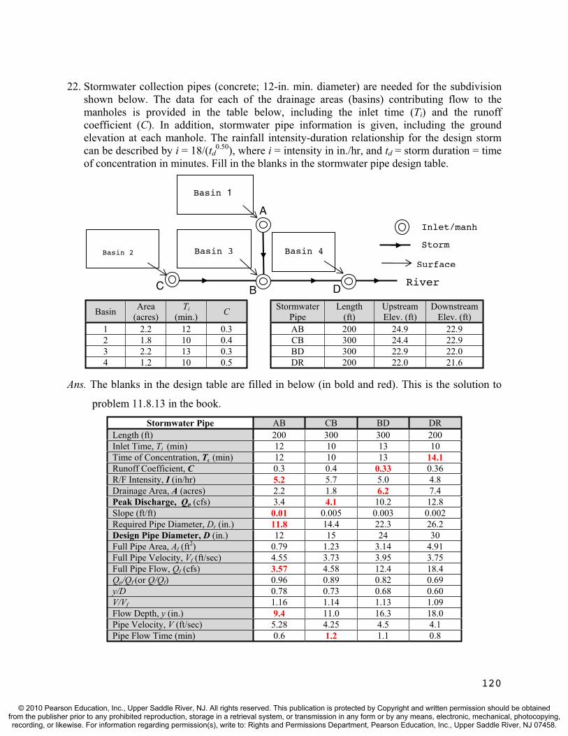
22. Stormwater collection pipes (concrete; 12-in. min. diameter) are needed for the subdivision shown below. The data for each of the drainage areas (basins) contributing flow to the manholes is provided in the table below, including the inlet time (Ti) and the runoff coefficient (C). In addition, stormwater pipe information is given, including the ground elevation at each manhole. The rainfall intensity-duration relationship for the design storm can be described by i = 18/(td
0.50), where i = intensity in in./hr, and td = storm duration = time of concentration in minutes. Fill in the blanks in the stormwater pipe design table.
A
Basin Area (acres)
Ti(min.) C Stormwater
Pipe Length
(ft) Upstream Elev. (ft)
Downstream Elev. (ft)
1 2.2 12 0.3 AB 200 24.9 22.9 2 1.8 10 0.4 CB 300 24.4 22.9 3 2.2 13 0.3 BD 300 22.9 22.0 4 1.2 10 0.5 DR 200 22.0 21.6
Ans. The blanks in the design table are filled in below (in bold and red). This is the solution to
problem 11.8.13 in the book.
Stormwater Pipe AB CB BD DRLength (ft) 200 300 300 200 Inlet Time, Ti (min) 12 10 13 10 Time of Concentration, Tc (min) 12 10 13 14.1 Runoff Coefficient, C 0.3 0.4 0.33 0.36 R/F Intensity, I (in/hr) 5.2 5.7 5.0 4.8 Drainage Area, A (acres) 2.2 1.8 6.2 7.4 Peak Discharge, Qp (cfs) 3.4 4.1 10.2 12.8 Slope (ft/ft) 0.01 0.005 0.003 0.002 Required Pipe Diameter, Dr (in.) 11.8 14.4 22.3 26.2 Design Pipe Diameter, D (in.) 12 15 24 30 Full Pipe Area, Af (ft2) 0.79 1.23 3.14 4.91 Full Pipe Velocity, Vf (ft/sec) 4.55 3.73 3.95 3.75 Full Pipe Flow, Qf (cfs) 3.57 4.58 12.4 18.4 Qp/Qf (or Q/Qf) 0.96 0.89 0.82 0.69 y/D 0.78 0.73 0.68 0.60 V/Vf 1.16 1.14 1.13 1.09 Flow Depth, y (in.) 9.4 11.0 16.3 18.0 Pipe Velocity, V (ft/sec) 5.28 4.25 4.5 4.1 Pipe Flow Time (min) 0.6 1.2 1.1 0.8
Surface
BC DRiver
Basin 1
Basin 2 Basin 3 Basin 4
Inlet/manh
Storm
120
© 2010 Pearson Education, Inc., Upper Saddle River, NJ. All rights reserved. This publication is protected by Copyright and written permission should be obtainedfrom the publisher prior to any prohibited reproduction, storage in a retrieval system, or transmission in any form or by any means, electronic, mechanical, photocopying,recording, or likewise. For information regarding permission(s), write to: Rights and Permissions Department, Pearson Education, Inc., Upper Saddle River, NJ 07458.
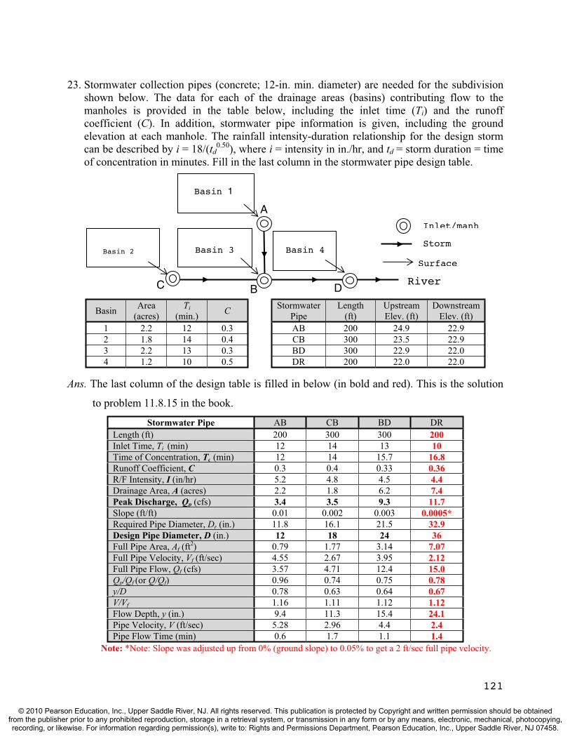
23. Stormwater collection pipes (concrete; 12-in. min. diameter) are needed for the subdivision shown below. The data for each of the drainage areas (basins) contributing flow to the manholes is provided in the table below, including the inlet time (Ti) and the runoff coefficient (C). In addition, stormwater pipe information is given, including the ground elevation at each manhole. The rainfall intensity-duration relationship for the design storm can be described by i = 18/(td
0.50), where i = intensity in in./hr, and td = storm duration = time of concentration in minutes. Fill in the last column in the stormwater pipe design table.
A
121
Basin Area (acres)
Ti(min.) C Stormwater
Pipe Length
(ft) Upstream Elev. (ft)
Downstream Elev. (ft)
1 2.2 12 0.3 AB 200 24.9 22.9 2 1.8 14 0.4 CB 300 23.5 22.9 3 2.2 13 0.3 BD 300 22.9 22.0 4 1.2 10 0.5 DR 200 22.0 22.0
Ans. The last column of the design table is filled in below (in bold and red). This is the solution
to problem 11.8.15 in the book.
Stormwater Pipe AB CB BD DRLength (ft) 200 300 300 200 Inlet Time, Ti (min) 12 14 13 10 Time of Concentration, Tc (min) 12 14 15.7 16.8 Runoff Coefficient, C 0.3 0.4 0.33 0.36 R/F Intensity, I (in/hr) 5.2 4.8 4.5 4.4 Drainage Area, A (acres) 2.2 1.8 6.2 7.4 Peak Discharge, Qp (cfs) 3.4 3.5 9.3 11.7 Slope (ft/ft) 0.01 0.002 0.003 0.0005* Required Pipe Diameter, Dr (in.) 11.8 16.1 21.5 32.9 Design Pipe Diameter, D (in.) 12 18 24 36 Full Pipe Area, Af (ft2) 0.79 1.77 3.14 7.07 Full Pipe Velocity, Vf (ft/sec) 4.55 2.67 3.95 2.12 Full Pipe Flow, Qf (cfs) 3.57 4.71 12.4 15.0 Qp/Qf (or Q/Qf) 0.96 0.74 0.75 0.78 y/D 0.78 0.63 0.64 0.67 V/Vf 1.16 1.11 1.12 1.12 Flow Depth, y (in.) 9.4 11.3 15.4 24.1 Pipe Velocity, V (ft/sec) 5.28 2.96 4.4 2.4 Pipe Flow Time (min) 0.6 1.7 1.1 1.4
Note: *Note: Slope was adjusted up from 0% (ground slope) to 0.05% to get a 2 ft/sec full pipe velocity.
Surface
BC DRiver
Basin 1
Basin 2 Basin 3 Basin 4
Inlet/manh
Storm
© 2010 Pearson Education, Inc., Upper Saddle River, NJ. All rights reserved. This publication is protected by Copyright and written permission should be obtainedfrom the publisher prior to any prohibited reproduction, storage in a retrieval system, or transmission in any form or by any means, electronic, mechanical, photocopying,recording, or likewise. For information regarding permission(s), write to: Rights and Permissions Department, Pearson Education, Inc., Upper Saddle River, NJ 07458.
TEST QUESTIONS & PROBLEMS - CHAPTER #12
Short Answer Questions
1. Identify two changes in a watershed that would affect the hydrologic homogeneity of a data set containing annual maximum stream flows.Ans. Hydrologic homogeneity would be affected by urbanization, relocated gages, streamflow
diversions, and construction of dams and reservoirs during the data collection period.
2. or F) An annual maximum series is formed using the highest N values on a data record which is N years long. (T
Ans. False. This is annual exceedence series.
3. Random hydrologic variables include all of the following except: a) mean sea level b) precipitation c) flood flows d) annual evaporation e) wind speedAns. (a) Mean sea level is found from random variables (sea level elevation).
4. (T or F) The 50 largest stream flows in a 50-year gage record represents a population.Ans. False. It represents a sample of all of the largest flows that could occur on that stream.
5. Identify three statistical parameters that are useful in analyzing probability distributions.Ans. Mean, standard deviation, and skewness.
6. Which of the following probability distributions is rarely used in hydrologic applications? a) Normal b) Log-Normal c) Log-Pearson Type III d) Gumbel Ans. (a) Normal. Most hydrologic random variables are not normally distributed.
7. (T or F) The probability distribution recommended to model annual maximum streamflow series by the Interagency Advisory Committee on Water Data, U.S. Geological Survey is the Log-Pearson Type III distribution. Ans. True.
8. Define the term return period, also called the recurrence interval.Ans. Return period is the average number of years between occurrences of a hydrologic event with a certain magnitude or greater.
9. A 3,000 cfs flood has an annual probability of exceedence of 20%. What is its return period? Ans. Tr = 1/p = 1/0.20 = 5 years.
10. (T or F) Hydrologic risk is the probability that the design discharge will be exceeded once during the service life of the project. Ans. False. It could be exceeded one time or more during the service life of the project.
11. In the closed form frequency function: xT = m + KT(s), what does xT represent?? Ans. xT is the magnitude of a hydrologic variable corresponding to specified return period, T.
122
© 2010 Pearson Education, Inc., Upper Saddle River, NJ. All rights reserved. This publication is protected by Copyright and written permission should be obtainedfrom the publisher prior to any prohibited reproduction, storage in a retrieval system, or transmission in any form or by any means, electronic, mechanical, photocopying,recording, or likewise. For information regarding permission(s), write to: Rights and Permissions Department, Pearson Education, Inc., Upper Saddle River, NJ 07458.
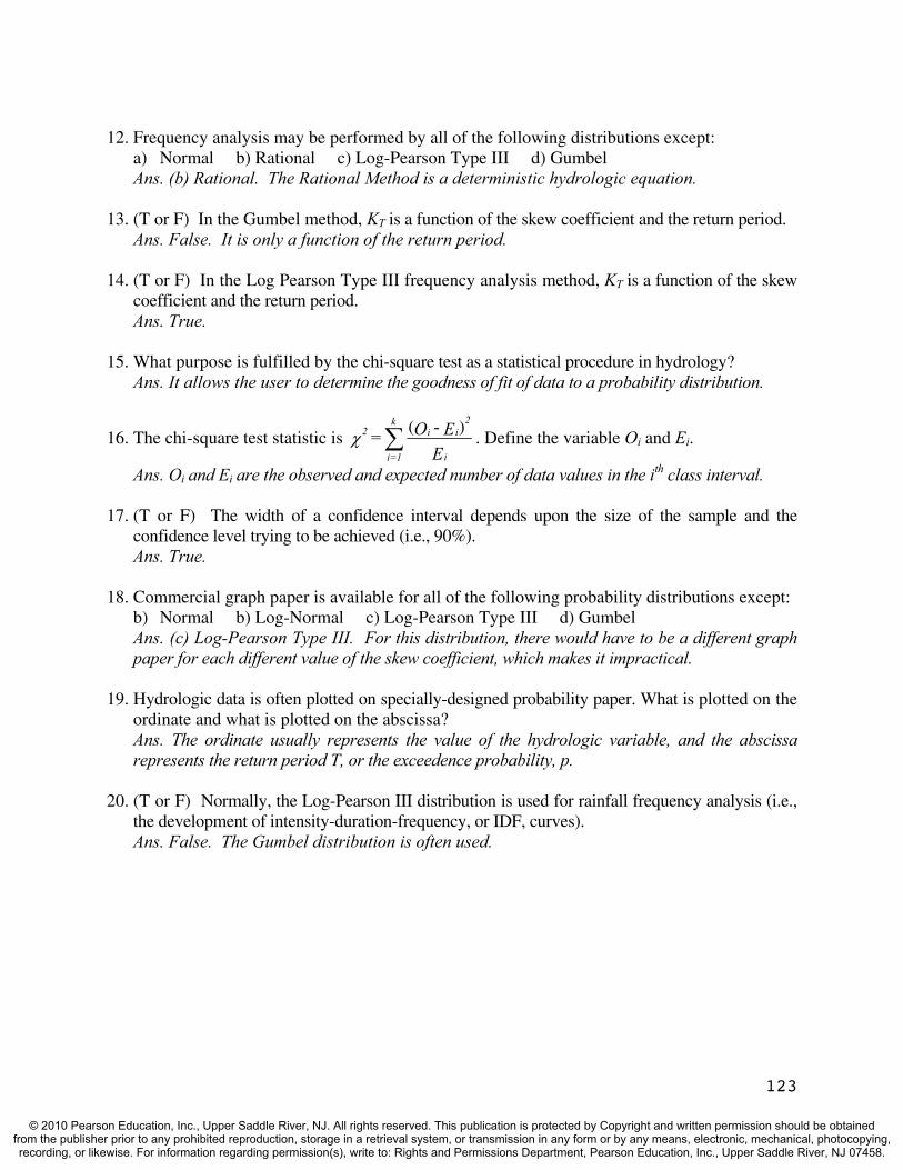
12. Frequency analysis may be performed by all of the following distributions except: a) Normal b) Rational c) Log-Pearson Type III d) Gumbel Ans. (b) Rational. The Rational Method is a deterministic hydrologic equation.
13. (T or F) In the Gumbel method, KT is a function of the skew coefficient and the return period. Ans. False. It is only a function of the return period.
14. (T or F) In the Log Pearson Type III frequency analysis method, KT is a function of the skew coefficient and the return period. Ans. True.
15. What purpose is fulfilled by the chi-square test as a statistical procedure in hydrology? Ans. It allows the user to determine the goodness of fit of data to a probability distribution.
16. The chi-square test statistic is E
E - O = i
ii2k
1=i
2 )(. Define the variable Oi and Ei.
Ans. Oi and Ei are the observed and expected number of data values in the ith class interval.
17. (T or F) The width of a confidence interval depends upon the size of the sample and the confidence level trying to be achieved (i.e., 90%). Ans. True.
18. Commercial graph paper is available for all of the following probability distributions except: b) Normal b) Log-Normal c) Log-Pearson Type III d) Gumbel Ans. (c) Log-Pearson Type III. For this distribution, there would have to be a different graph paper for each different value of the skew coefficient, which makes it impractical.
19. Hydrologic data is often plotted on specially-designed probability paper. What is plotted on the ordinate and what is plotted on the abscissa? Ans. The ordinate usually represents the value of the hydrologic variable, and the abscissa represents the return period T, or the exceedence probability, p.
20. (T or F) Normally, the Log-Pearson III distribution is used for rainfall frequency analysis (i.e., the development of intensity-duration-frequency, or IDF, curves). Ans. False. The Gumbel distribution is often used.
123
© 2010 Pearson Education, Inc., Upper Saddle River, NJ. All rights reserved. This publication is protected by Copyright and written permission should be obtainedfrom the publisher prior to any prohibited reproduction, storage in a retrieval system, or transmission in any form or by any means, electronic, mechanical, photocopying,recording, or likewise. For information regarding permission(s), write to: Rights and Permissions Department, Pearson Education, Inc., Upper Saddle River, NJ 07458.

Problems
1. The table below is used to evaluate the statistical parameters of an annual peak discharge (m3/sec) data record. Fill in the blanks in the table and evaluate the mean, standard deviation, and skewness of the original data set.
Ans. The blanks in the table are filled in and given below (in bold and red). The statistical
parameters are solved for below the table.
Year Qi Qi - m (Qi - m)2 (Qi - m)3
2000 114 -7.70E+01 5.93E+03 -4.57E+05
2001 294 1.03E+02 1.06E+04 1.09E+06
2002 113 -7.80E+01 6.08E+03 -4.75E+05
2003 101 -9.00E+01 8.10E+03 -7.29E+05
2004 222 3.10E+01 9.61E+02 2.98E+04
2005 276 8.50E+01 7.23E+03 6.14E+05
2006 215 2.40E+01 5.76E+02 1.38E+04
2007 250 5.90E+01 3.48E+03 2.05E+05 2008 147 -4.40E+01 1.94E+03 -8.52E+04
2009 178 -1.30E+01 1.69E+02 -2.20E+03
Sum 1910 0.00E+00 4.51E+04 2.08E+05
Q N1 = m i
N
=1i= (1,910)/10 = 191 m3/sec
m-Q 1-N
1 = s i
N
=1i
1/22)( = [45,100/9]1/2 = 70.8 m3/sec
s 2-N 1-N
m-Q N =G 3
i3
N
=1i
)()(
)( = (10)(2.08E+05)/[(9)(8)(70.8)3] = 0.0814
2. The table below is used to evaluate the statistical parameters of an annual flood flow record. Fill in the blanks in the table and evaluate the mean, standard deviation, and skewness of the log transformed data set.
124
© 2010 Pearson Education, Inc., Upper Saddle River, NJ. All rights reserved. This publication is protected by Copyright and written permission should be obtainedfrom the publisher prior to any prohibited reproduction, storage in a retrieval system, or transmission in any form or by any means, electronic, mechanical, photocopying,recording, or likewise. For information regarding permission(s), write to: Rights and Permissions Department, Pearson Education, Inc., Upper Saddle River, NJ 07458.

Ans. The blanks in the table are filled in and given below (in bold and red). The statistical
parameters are solved for below the table.
Year Qi log Qi (logQi-ml) (logQi-ml)2 (logQi-ml)
3
2000 114 2.06E+00 -1.95E-01 3.80E-02 -7.40E-03
2001 294 2.47E+00 2.17E-01 4.69E-02 1.02E-02
2002 113 2.05E+00 -1.99E-01 3.95E-02 -7.85E-03
2003 101 2.00E+00 -2.47E-01 6.12E-02 -1.52E-02
2004 222 2.35E+00 9.45E-02 8.94E-03 8.45E-04
2005 276 2.44E+00 1.89E-01 3.58E-02 6.76E-03
2006 215 2.33E+00 8.06E-02 6.50E-03 5.24E-04
2007 250 2.40E+00 1.46E-01 2.14E-02 3.12E-03
2008 147 2.17E+00 -8.45E-02 7.14E-03 -6.03E-04
2009 178 2.25E+00 -1.38E-03 1.91E-06 -2.65E-09 Sum 1910 2.25E+01 -2.22E-15 2.65E-01 -9.60E-03
i
N
=1il Q
N1 = m log = (22.5)/10 = 2.25
m-Q 1-N
1 = s li
N
=1i
1/2
l2)(log = [0.265/9]1/2 = 0.172
l3
li3
N
=1il s 2-N 1-N
m-P N = G
)()(
)log( = (10)(-9.60E-03)/[(9)(8)(0.172)3] = -0.262
3. A chemical industry needs to make repairs to its wastewater treatment plant which is located near the river. A levee is built to protect the construction work from the 10-year flood. What is the probability that the construction site will be flooded in the three year construction period? What is the probability that it will not be flooded? What is the probability that it will be flooded every year for the next 3 years?
Ans. The probability of being flooded in any one year (Eq’n 12.22) is p = 1/10 = 0.10 = 10 %
The probability of being flooded at least once in the next three years (Equation 12.23) is,
R = 1 – (1 – 0.10)3 = 0.271 = 27.1 %
The probability of not being flooded in 3 years: 1 – R = 1 – 0.271 = 0.729 = 72.9%
The probability of being flooded all three years is: (0.1)(0.1)(0.1) = 0.001 = 0.1%
125
© 2010 Pearson Education, Inc., Upper Saddle River, NJ. All rights reserved. This publication is protected by Copyright and written permission should be obtainedfrom the publisher prior to any prohibited reproduction, storage in a retrieval system, or transmission in any form or by any means, electronic, mechanical, photocopying,recording, or likewise. For information regarding permission(s), write to: Rights and Permissions Department, Pearson Education, Inc., Upper Saddle River, NJ 07458.

4. A 10-year record of annual peak discharges (cfs) are provided below for the Wabash River. The statistical parameters for this annual series are: m = 191 cfs, s = 70.8 cfs, and G = 0.0814. Determine the 10-year flood assuming the data fits a normal distribution. Also determine the return interval for the 2005 flood (276 cfs) assuming the data fits a Gumbel distribution.
Year 2000 2001 2002 2003 2004 2005 2006 2007 2008 2009Qi 114 294 113 101 222 276 215 250 147 178
Ans. Normal: K10 = 1.282 from Table 12.2 for p = 0.10 (T = 10 years). Then from Eq’n (12.24)
Q10 = m + K10(s) = 191 + 1.282(70.8) = 282 cfs
Gumbel: Using Eq’n (12.24) with QT = 276 cfs
QT = m + KT(s); 276 = 191 + KT (70.8); KT = 1.20; from Table 12.2, we can see that this
is a little less than a 10-year flood, T 9 years.
5. A 10-year record of annual peak discharges (cfs) are provided below for the Wabash River. The statistical parameters for this annual series are: ml = 2.25, sl = 0.172, and Gl = -0.262. Determine the 10-year flood assuming the data fits a Log-Pearson III distribution. Also determine the return interval for the 2005 flood (276 cfs) assuming the data fits a Log-Normal distribution.
Year 2000 2001 2002 2003 2004 2005 2006 2007 2008 2009Qi 114 294 113 101 222 276 215 250 147 178
Ans. Log-Pearson Type III: Use Equations (12.31a), (12.29a), (12.28), and (12.30).
k = Gl/6 = -0.262/6 = -0.0437; w = [ln T2]1/2 = [ln 102]1/2 = 2.15
32
2
)15.2(001308.0)15.2(189269.015.2432788.11
)15.2(010328.015.2802853.0515517.215.2
+ + + + + - =z = 1.29
KT = z + (z2 – 1)k + (z3 – 6z)(k2/3) – (z2 – 1)k3 + zk4 + k5/3
KT = 1.29 + (1.292 – 1)(-0.0437) + (1.293 – 6·1.29){(-0.0437)2/3) – (1.292 – 1)(-0.0437)3 +
1.29·(-0.0437)4 + (-0.0437)5/3 = 1.29; Now from Equation (12.25)
log Q10 = ml + KT(sl) = 2.25 + 1.29(0.172) = 2.47; therefore Q10 = 295 cfs
Log-Normal: Use Eq’n (12.24) with QT = 276 cfs
log QT = ml + KT(sl); log (276) = 2.25 + KT (0.172); KT = 1.11;
From Table 12.2, we can this is a little less than a 10-year flood, T 8 years.
126
© 2010 Pearson Education, Inc., Upper Saddle River, NJ. All rights reserved. This publication is protected by Copyright and written permission should be obtainedfrom the publisher prior to any prohibited reproduction, storage in a retrieval system, or transmission in any form or by any means, electronic, mechanical, photocopying,recording, or likewise. For information regarding permission(s), write to: Rights and Permissions Department, Pearson Education, Inc., Upper Saddle River, NJ 07458.
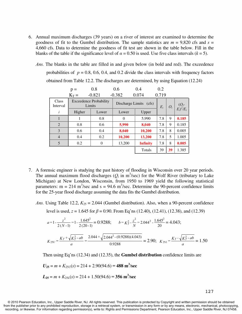
6. Annual maximum discharges (39 years) on a river of interest are examined to determine the goodness of fit to the Gumbel distribution. The sample statistics are m = 9,820 cfs and s = 4,660 cfs. Data to determine the goodness of fit test are shown in the table below. Fill in the blanks of the table if the significance level of = 0.50 is used. Use five class intervals (k = 5).
Ans. The blanks in the table are filled in and given below (in bold and red). The exceedence
probabilities of p = 0.8, 0.6, 0.4, and 0.2 divide the class intervals with frequency factors
obtained from Table 12.2. The discharges are determined, by using Equation (12.24)
p = 0.8 0.6 0.4 0.2KT = -0.821 -0.382 0.074 0.719
ClassInterval
Exceedence Probability Limits
Discharge Limits (cfs) Ei Oi
(Oi-Ei)
2/Eii Higher Lower Lower Upper
1 1 0.8 0 5,990 7.8 9 0.185 2 0.8 0.6 5,990 8,040 7.8 9 0.185
3 0.6 0.4 8,040 10,200 7.8 8 0.005
4 0.4 0.2 10,200 13,200 7.8 5 1.005
5 0.2 0 13,200 Infinity 7.8 8 0.005
Totals 39 39 1.385
7. A forensic engineer is studying the past history of flooding in Wisconsin over 20 year periods. The annual maximum flood discharges (Qi in m3/sec) for the Wolf River (tributary to Lake Michigan) at New London, Wisconsin, from 1950 to 1969 yield the following statistical parameters: m = 214 m3/sec and s = 94.6 m3/sec. Determine the 90-percent confidence limits for the 25-year flood discharge assuming the data fits the Gumbel distribution.
Ans. Using Table 12.2, K25 = 2.044 (Gumbel distribution). Also, when a 90-percent confidence
level is used, z = 1.645 for = 0.90. From Eq’ns (12.40), (12.41), (12.38), and (12.39)
)120(2645.11
)1(21
22
- - =
- N z - = a = 0.9288;
20645.1044.2
22
22 - =
Nz - K = b T = 4.043;
9288.0
)043.4)(9288.0(044.2044.2 22
25
- + =
aab - K + K = K TT
U = 2.90;a
ab - K - K = K TTL
2
25 = 1.50
Then using Eq’ns (12.34) and (12.35), the Gumbel distribution confidence limits are
U25 = m + K25U(s) = 214 + 2.90(94.6) = 488 m3/sec
L25 = m + K25L(s) = 214 + 1.50(94.6) = 356 m3/sec
127
© 2010 Pearson Education, Inc., Upper Saddle River, NJ. All rights reserved. This publication is protected by Copyright and written permission should be obtainedfrom the publisher prior to any prohibited reproduction, storage in a retrieval system, or transmission in any form or by any means, electronic, mechanical, photocopying,recording, or likewise. For information regarding permission(s), write to: Rights and Permissions Department, Pearson Education, Inc., Upper Saddle River, NJ 07458.

128
8. Annual maximum discharges (39 years) on a river of interest are examined to determine the 90% confidence limits for the 1.25-, 2-, 10-, 25-, 50-, 100- and 200-year peak discharges. The sample statistics are ml = 3.95 and sl = 0.197. If the Log-Normal distribution is shown to fit the data, fill in the blanks of the computational table below.
Ans. The blanks in the table are filled in and given below (in bold and red). This is actually
the solution to Example 12.8 in the textbook.
1 2 3 4 5 6 7 8 9 10 11 12
T KT log QT QT a b KTU KTL log UT log LT UT LT
1.25 -0.841 3.78 6.09E+03 0.964 0.638 -0.557 -1.187 3.840 3.716 6.92E+03 5.20E+03
2 0 3.95 8.91E+03 0.964 -0.069 0.268 -0.268 4.003 3.897 1.01E+04 7.89E+03
10 1.282 4.20 1.59E+04 0.964 1.574 1.697 0.962 4.284 4.140 1.92E+04 1.38E+04
25 1.751 4.29 1.97E+04 0.964 2.997 2.251 1.381 4.393 4.222 2.47E+04 1.67E+04
50 2.054 4.35 2.26E+04 0.964 4.150 2.613 1.647 4.465 4.274 2.92E+04 1.88E+04
100 2.327 4.41 2.56E+04 0.964 5.346 2.941 1.884 4.529 4.321 3.38E+04 2.10E+04
200 2.576 4.46 2.87E+04 0.964 6.566 3.242 2.100 4.589 4.364 3.88E+04 2.31E+04
9. Annual precipitation measurements (Pi in inches) at location X for a 20-year period are listed below. The distribution is Normal based on a chi-square test. If the data were to be plotted on Normal distribution (probability) paper, determine plotting positions (exceedence probability and return period) for two of the rainfall depths: 47.6 in. and 35.8 in. In addition, the mean, standard deviation, and the skew coefficient for this annual series were computed to be: m = 40.0 in., s = 3.50 in., and G = 0.296. Determine the 2-, 5-, and 20-year rainfall depths in order to draw the theoretical (straight line) probability distribution on Normal distribution paper.
Year 1989 1990 1991 1992 1993 1994 1995 1996 1997 1998Pi 44.2 47.6 38.5 35.8 40.2 41.2 38.8 39.7 40.5 42.5
Year 1999 2000 2001 2002 2003 2004 2005 2006 2007 2008Pi 39.2 38.3 46.1 33.1 35.0 39.3 42.0 41.7 37.7 38.6
Ans. The rank, r, of the two precipitation depths is determined and the exceedence probability,
p, and the return period, T, are found using Equations (12.43) and (12.44):
For P = 47.6 in., r = 1; p = r/(N + 1) = 1/(20 + 1) = 0.0476; T = 1/p = 21.0 years
For P = 35.8 in., r = 18; p = r/(N + 1) = 18/(20 + 1) = 0.857; T = 1/p = 1.17 years
The theoretical probability distribution is found using Equation (12.24) and Table 12.2:
P2 = m + K2(s) = 40.0 + 0.00(3.50) = 40.0 in.
P5 = m + K10(s) = 40.0 + 0.841(3.50) = 42.9 in.
P20 = m + K25(s) = 40.0 + 1.645(3.50) = 45.8 in.
© 2010 Pearson Education, Inc., Upper Saddle River, NJ. All rights reserved. This publication is protected by Copyright and written permission should be obtainedfrom the publisher prior to any prohibited reproduction, storage in a retrieval system, or transmission in any form or by any means, electronic, mechanical, photocopying,recording, or likewise. For information regarding permission(s), write to: Rights and Permissions Department, Pearson Education, Inc., Upper Saddle River, NJ 07458.