manual goodman tstatg1100-2 rev 1 · pdf filecaution follow installation instructions...
TRANSCRIPT
Air Conditioning & Heating
Model TSTATG1100-2
Dig i tal Thermostat Non-Programmable
1-Heat & 1-Cool
Gas/Electric Heat Pump
Battery or System Powered
Fahrenheit or Celsius
Fully Electronic
Owner ’s ManualThank goodness for Goodman.
TM
Page 2
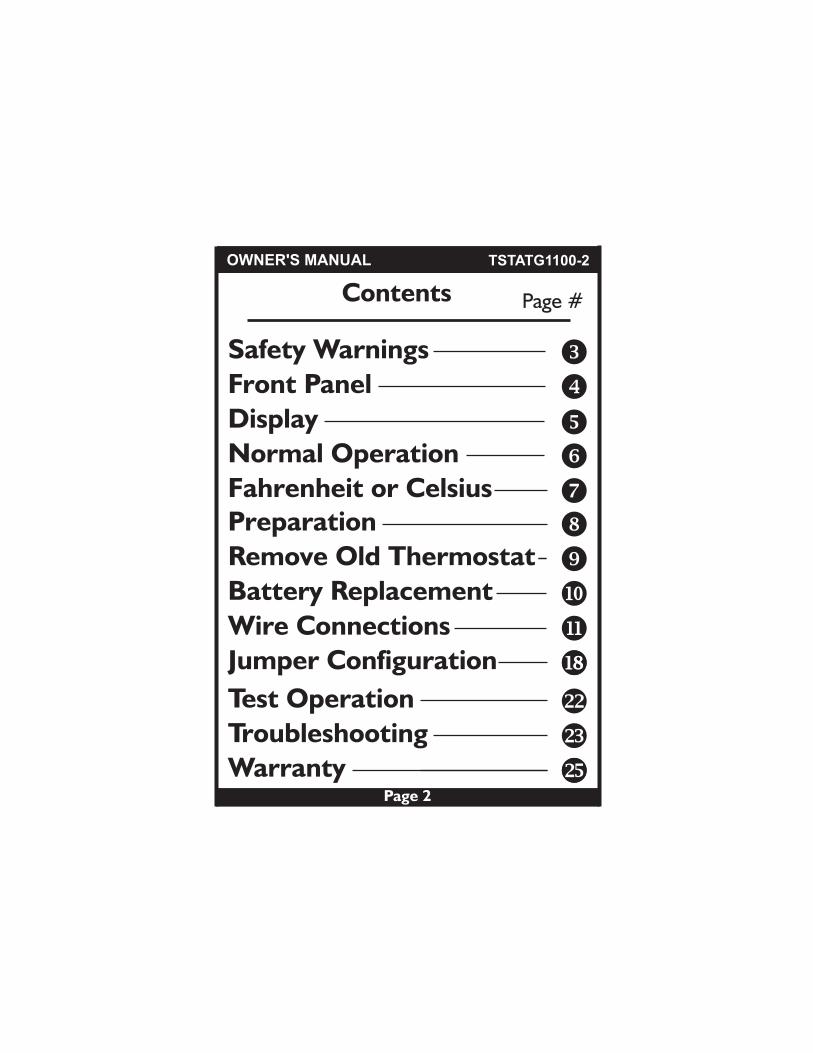
Contents Page #
Remove Old Thermostat
Safety Warnings
Front Panel
Display
Normal Operation
Preparation
Battery Replacement
Warranty
Test Operation
Troubleshooting
Wire ConnectionsJumper Configuration
OWNER'S MANUAL TSTATG1100-2
Fahrenheit or Celsius
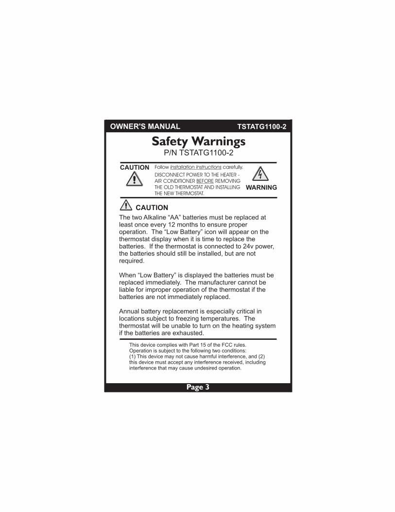
CAUTION Follow Installation Instructions carefully.
DISCONNECT POWER TO THE HEATER - AIR CONDITIONER BEFORE REMOVINGTHE OLD THERMOSTAT AND INSTALLINGTHE NEW THERMOSTAT.
WARNING
Page 3
Safety Warnings
CAUTION
This device complies with Part 15 of the FCC rules. Operation is subject to the following two conditions:(1) This device may not cause harmful interference, and (2) this device must accept any interference received, including interference that may cause undesired operation.
OWNER'S MANUAL
P/N TSTATG1100-2
The two Alkaline “AA” batteries must be replaced at least once every 12 months to ensure proper operation. The “Low Battery” icon will appear on the thermostat display when it is time to replace the batteries. If the thermostat is connected to 24v power, the batteries should still be installed, but are not required.
When “Low Battery” is displayed the batteries must be replaced immediately. The manufacturer cannot be liable for improper operation of the thermostat if the batteries are not immediately replaced.
Annual battery replacement is especially critical in locations subject to freezing temperatures. The thermostat will be unable to turn on the heating system if the batteries are exhausted.
TSTATG1100-2

BATTERIES
COOL
OFF
FAN
HEAT
AUTO
ON
75HEAT
Page 4
Front Panel
OWNER'S MANUAL
BATTERYDOOR
On or AutoFAN SWITCH
COOLER & WARMERBUTTONS
DISPLAY
MODE SWITCHCool, Off or Heat
TSTATG1100-2
BI-COLOR LEDHeat or Cool demand indicator when system powered: Red = HeatGreen = Cool
88
Page 5
Display
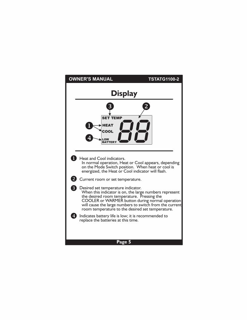
Heat and Cool indicators. In normal operation, Heat or Cool appears, depending on the Mode Switch position. When heat or cool is energized, the Heat or Cool indicator will flash.
Desired set temperature indicator. When this indicator is on, the large numbers represent the desired room temperature. Pressing the COOLER or WARMER button during normal operation will cause the large numbers to switch from the current room temperature to the desired set temperature.
Current room or set temperature.
Indicates battery life is low; it is recommended to replace the batteries at this time.
OWNER'S MANUAL
SET TEMP
HEAT
COOL
LOWBATTERY
TSTATG1100-2
Page 6
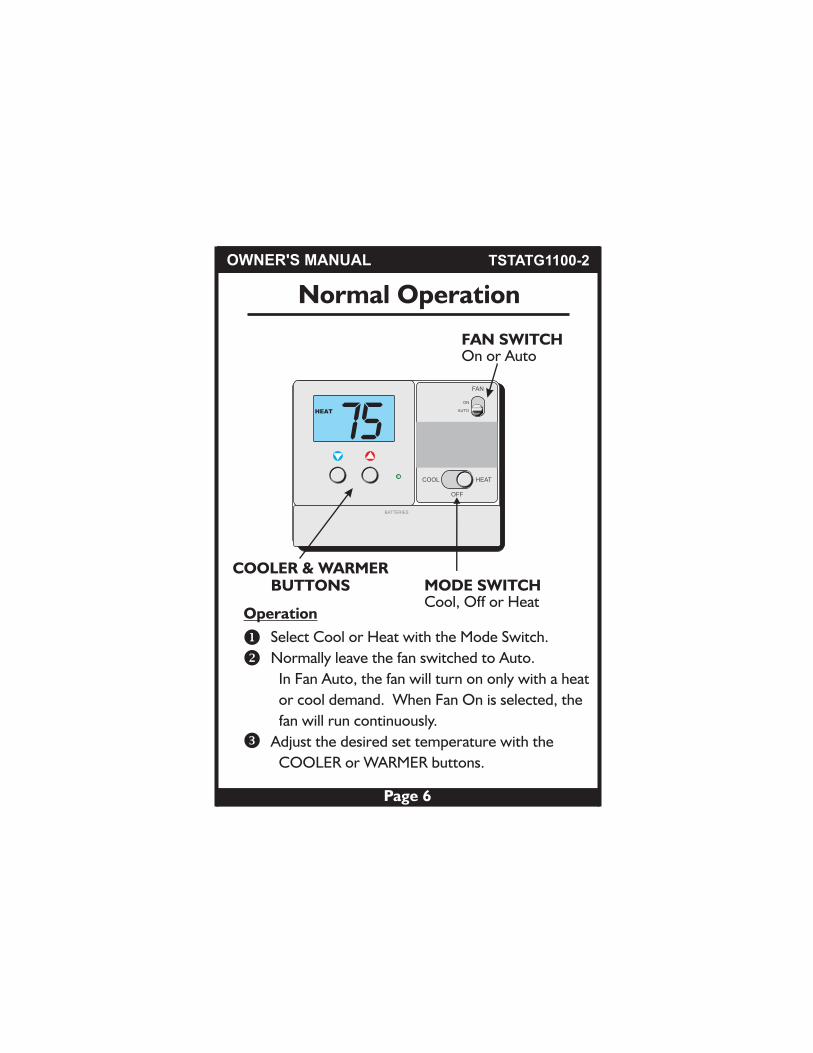
Normal Operation
OWNER'S MANUAL
Operation
Select Cool or Heat with the Mode Switch.
Normally leave the fan switched to Auto.
In Fan Auto, the fan will turn on only with a heat
or cool demand. When Fan On is selected, the
fan will run continuously.
Adjust the desired set temperature with the
COOLER or WARMER buttons.
TSTATG1100-2
BATTERIES
COOL
OFF
FAN
HEAT
AUTO
ON
On or AutoFAN SWITCH
COOLER & WARMERBUTTONS MODE SWITCH
Cool, Off or Heat
75HEAT
Page 7
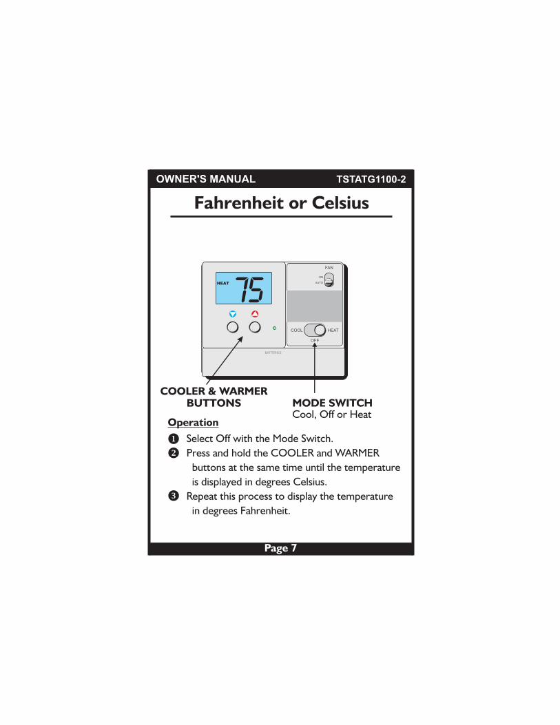
Fahrenheit or Celsius
OWNER'S MANUAL
Operation
Select Off with the Mode Switch.
Press and hold the COOLER and WARMER
buttons at the same time until the temperature
is displayed in degrees Celsius.
Repeat this process to display the temperature
in degrees Fahrenheit.
TSTATG1100-2
SET
HEAT
BATTERIES
COOL
OFF
FAN
HEAT
AUTO
ON
COOLER & WARMERBUTTONS MODE SWITCH
Cool, Off or Heat
75HEAT
Page 8
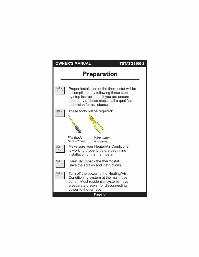
These tools will be required:
Flat BladeScrewdriver
Wire cutter& Stripper
Make sure your Heater/Air Conditioneris working properly before beginninginstallation of the thermostat.
Carefully unpack the thermostat.Save the screws and instructions.
Turn off the power to the Heating/AirConditioning system at the main fusepanel. Most residential systems have a separate breaker for disconnectingpower to the furnace.
Proper installation of the thermostat will beaccomplished by following these stepby step instructions. If you are unsureabout any of these steps, call a qualifiedtechnician for assistance.
Preparation
OWNER'S MANUAL TSTATG1100-2
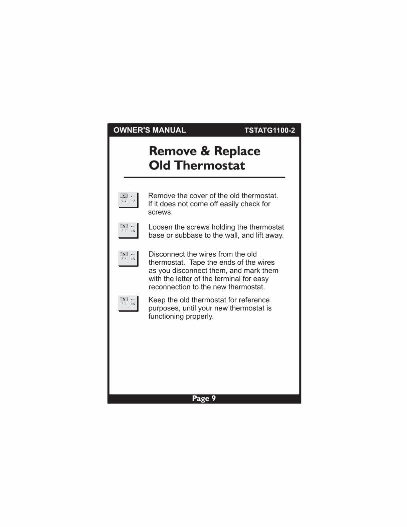
Remove the cover of the old thermostat.If it does not come off easily check forscrews.
Loosen the screws holding the thermostatbase or subbase to the wall, and lift away.
Disconnect the wires from the oldthermostat. Tape the ends of the wiresas you disconnect them, and mark themwith the letter of the terminal for easyreconnection to the new thermostat.
Keep the old thermostat for referencepurposes, until your new thermostat isfunctioning properly.
Remove & Replace Old Thermostat
Page 9
OWNER'S MANUAL TSTATG1100-2

Page 10
OWNER'S MANUAL TSTATG1100-2
Page 10
OWNER'S MANUAL TSTATG1100-2
SET
HEAT
Su
PMI2:00:
Battery ReplacementThe batteries are easily accessible from the batterydoor located on the bottom front of the thermostat (fig. 1). To open the battery slot, pull out on the battery door (fig. 1) and swing down (fig. 2).
Push up on the battery door and snap closed (fig. 4).
FIG. 2
Swing down
FIG. 4
Snap closedPush up
The batteries must be replaced immediately when the
FIG. 3
Oldbatteriesout
New batteriesin
Remove the old batteries and replace with the newAA alkaline batteries (fig. 3).
FIG. 1
BatteryDoor
Pull out
SET
HEAT
BATTERIES
COOL OFF HEAT
AA Alkaline
thermostat displays the Low Battery icon.

Page 11
Wire Connections
If the terminal designations on your oldthermostat do not match those on the new thermostat, refer to the chart belowor the wiring diagrams that follow.
Wire from theold thermostat
terminal markedFunction
Install on thenew thermostat
connector marked
C Common
Y1 or Y Cooling Y
W1, W or H Heating W
G or F Fan G
O/B Rev. Valve O/B
C (optional)
Thermal Insulating Sheet
RC, R, M, Vr, A Power RC* (Cooling Transformer)
RH, R, M, Vr, A Power RH* (Heating Transformer)
*The RC and RH terminals have a factory installed jumper to control single transformer systems. Remove this jumper to control dual transformer systems.
Wire Slots
INSTALLATION INSTRUCTIONS
A label is provided on the backplate that prevents drafts originating inside the wall from entering the thermostat. These drafts, left unchecked, may cause incorrect room temperature readings. Please do not remove this label from the thermostat. Insert the wires through the slots provided in the label as shown in Fig. 1.
C O/B Y W G RC RH
4Z95
MODEL: TSTATG1100-2
97061606MADE IN CHINA
USE SIZE “AA”ALKALINE BATTERIES
TSTATG1100-2

Page 12
Sample Wiring DiagramsGas or Electric Heat
POWER R
FAN G
COMPRESSOR YW
GAS ORELECTRIC HEAT
4 Conductor 18 to 22 gauge unshielded cable from the thermostat to the equipment.
Common wire is optional in all installations. If a common wire is not used thethermostat must be powered by two AA alkaline batteries. These batteries must be replaced (page 6) each year or when the Low Battery indicator is displayed (page 3).
*
4 Wire, 1 Stage Cooling, 1 Stage HeatingResidential Gas or Electric Heat, Electric Cool, split systems & package units. For jumper configuration see pages 14 and 15.
Common wire optional*
Factory installedjumper betweenRC and RH
INSTALLATION INSTRUCTIONS
C O/B Y W G RC RH
TSTATG1100-2

Sample Wiring DiagramsGas or Electric Heat
POWER
O
FAN
Y
REVERSING VALVE
RG
COMPRESSOR
4 Conductor 18 to 22 gauge unshielded cable from the thermostat to the equipment.
Common wire is optional in all installations. If a common wire is not used thethermostat must be powered by two AA alkaline batteries. These batteries must be replaced (page 6) each year or when the Low Battery indicator is displayed (page 3).
*
Common wire optional*
Factory installedjumper betweenRC and RH
INSTALLATION INSTRUCTIONS
C O/B Y W G RC RH
Page 13
4 Wire, 1 Stage Cooling, 1 Stage Heating-Heat Pump with O reversing valve.Residential Heat Pumps, split systems & package units, with no auxiliary heat.For jumper configuration see page 16.
TSTATG1100-2
Sample Wiring DiagramsGas or Electric Heat
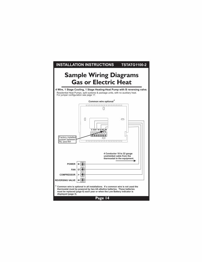
POWER
B
FAN
Y
REVERSING VALVE
RG
COMPRESSOR
4 Conductor 18 to 22 gauge unshielded cable from the thermostat to the equipment.
Common wire is optional in all installations. If a common wire is not used thethermostat must be powered by two AA alkaline batteries. These batteries must be replaced (page 6) each year or when the Low Battery indicator is displayed (page 3).
*
Common wire optional*
Factory installedjumper betweenRC and RH
INSTALLATION INSTRUCTIONS
C O/B Y W G RC RH
4 Wire, 1 Stage Cooling, 1 Stage Heating-Heat Pump with B reversing valve.Residential Heat Pumps, split systems & package units, with no auxiliary heat.For jumper configuration see page 17.
Page 14
TSTATG1100-2
Sample Wiring DiagramsGas or Electric Heat
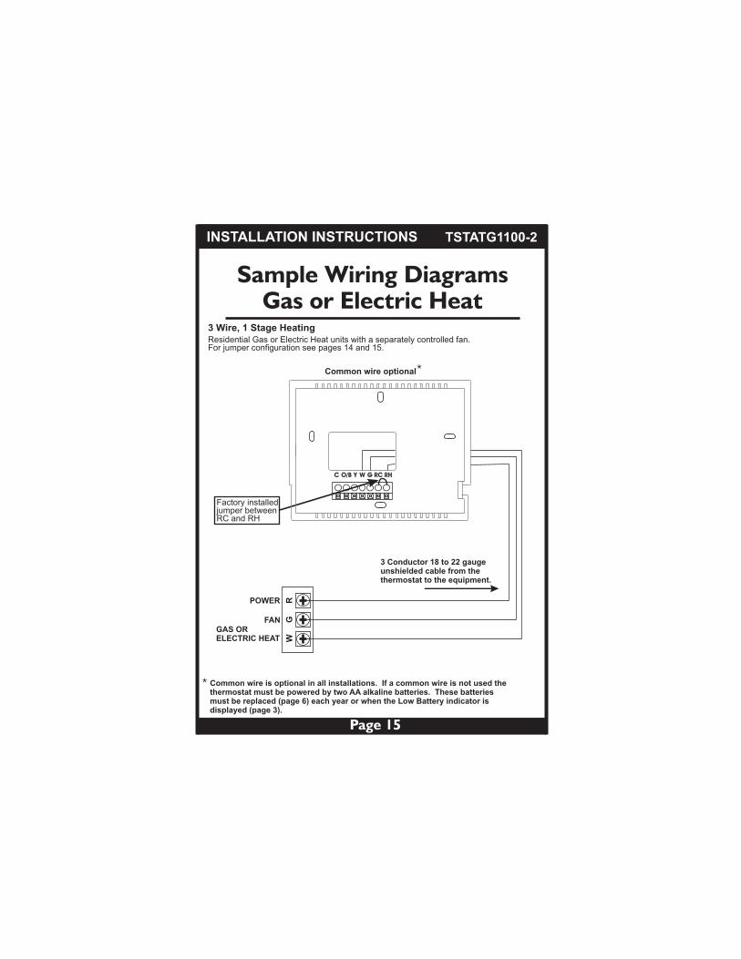
3 Conductor 18 to 22 gauge unshielded cable from the thermostat to the equipment.
Common wire is optional in all installations. If a common wire is not used thethermostat must be powered by two AA alkaline batteries. These batteries must be replaced (page 6) each year or when the Low Battery indicator is displayed (page 3).
*
Common wire optional*
Factory installedjumper betweenRC and RH
INSTALLATION INSTRUCTIONS
C O/B Y W G RC RH
Page 15
FAN
POWER
GR
W
GAS ORELECTRIC HEAT
3 Wire, 1 Stage HeatingResidential Gas or Electric Heat units with a separately controlled fan.For jumper configuration see pages 14 and 15.
TSTATG1100-2
Sample Wiring DiagramsGas or Electric Heat
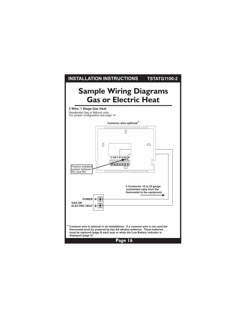
2 Conductor 18 to 22 gauge unshielded cable from the thermostat to the equipment.
Common wire is optional in all installations. If a common wire is not used thethermostat must be powered by two AA alkaline batteries. These batteries must be replaced (page 6) each year or when the Low Battery indicator is displayed (page 3).
*
Common wire optional*
Factory installedjumper betweenRC and RH
INSTALLATION INSTRUCTIONS
C O/B Y W G RC RH
POWER RW
GAS ORELECTRIC HEAT
Page 16
2 Wire, 1 Stage Gas HeatResidential Gas or Millivolt units.For jumper configuration see page 14.
TSTATG1100-2

Page 17
Sample Wiring DiagramsGas or Electric Heat
Dual Transformer 5 Wire, 1 Stage Cooling, 1 Stage HeatingResidential Gas or Electric Heat, Electric Cool, split systems & package units. For jumper configuration see pages 14 and 15.
Remove the factory installedjumper betweenRC and RH
5 Conductor 18 to 22 gauge unshielded cable from the thermostat to both sets of equipment.
COMPRESSOR YR
CPOWERCOOL
Cooling System
FAN
RH
G
GAS ORELECTRIC HEAT W
POWERHEAT
Heating System
If a common wire is used it must be connected to the furnace common terminal.If a common wire is not used the thermostat must be powered by two AA alkaline batteries. These batteries must be replaced (page 6) each year or when the Low Battery indicator is displayed (page 3).
*
Common wire optional*
INSTALLATION INSTRUCTIONS
C O/B Y W G RC RH
TSTATG1100-2
Page 18
Jumper Configuration
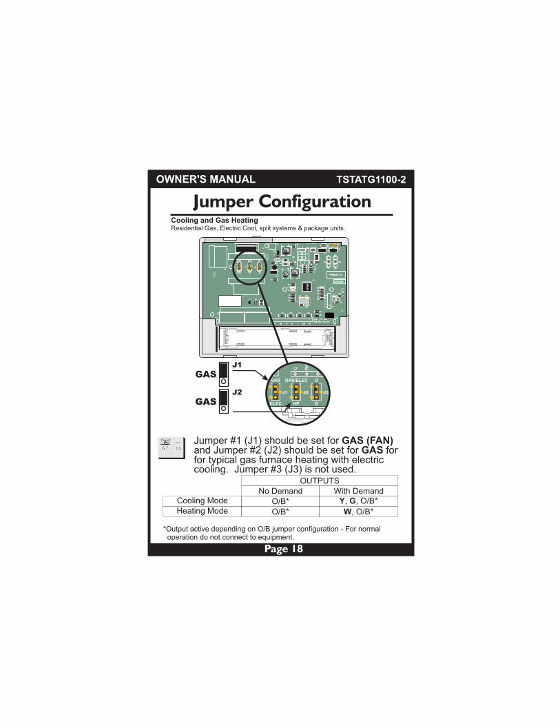
*Output active depending on O/B jumper configuration - For normal operation do not connect to equipment.
OUTPUTSNo Demand With Demand
Cooling ModeHeating Mode
O/B* Y, G, O/B*
O/B* W, O/B*
Cooling and Gas HeatingResidential Gas, Electric Cool, split systems & package units.
OWNER'S MANUAL
Jumper #1 (J1) should be set for GAS (FAN) and Jumper #2 (J2) should be set for GAS forfor typical gas furnace heating with electric cooling. Jumper #3 (J3) is not used.
TSTATG1100-2
10
00
JFK
SKD
10
00
JFK
SKD
10
00
JFK
SKD
471
471
471
471
471
471
471 471
471
471
471
471
471 471
471
471
471
471
471
471
ASDF
NN
E A
CP
JA
P4
S2
20
-5N
8 3
D4
471 471 471 471
471
471
471
471
471
471
471
471
ASDF
ASDF
471
ASD
F
GAS
ELEC
GAS/ELEC
HP
O
B
C
RH
Y
J3J2J1
GAS
GAS
J1
J2
Page 19
Jumper Configuration
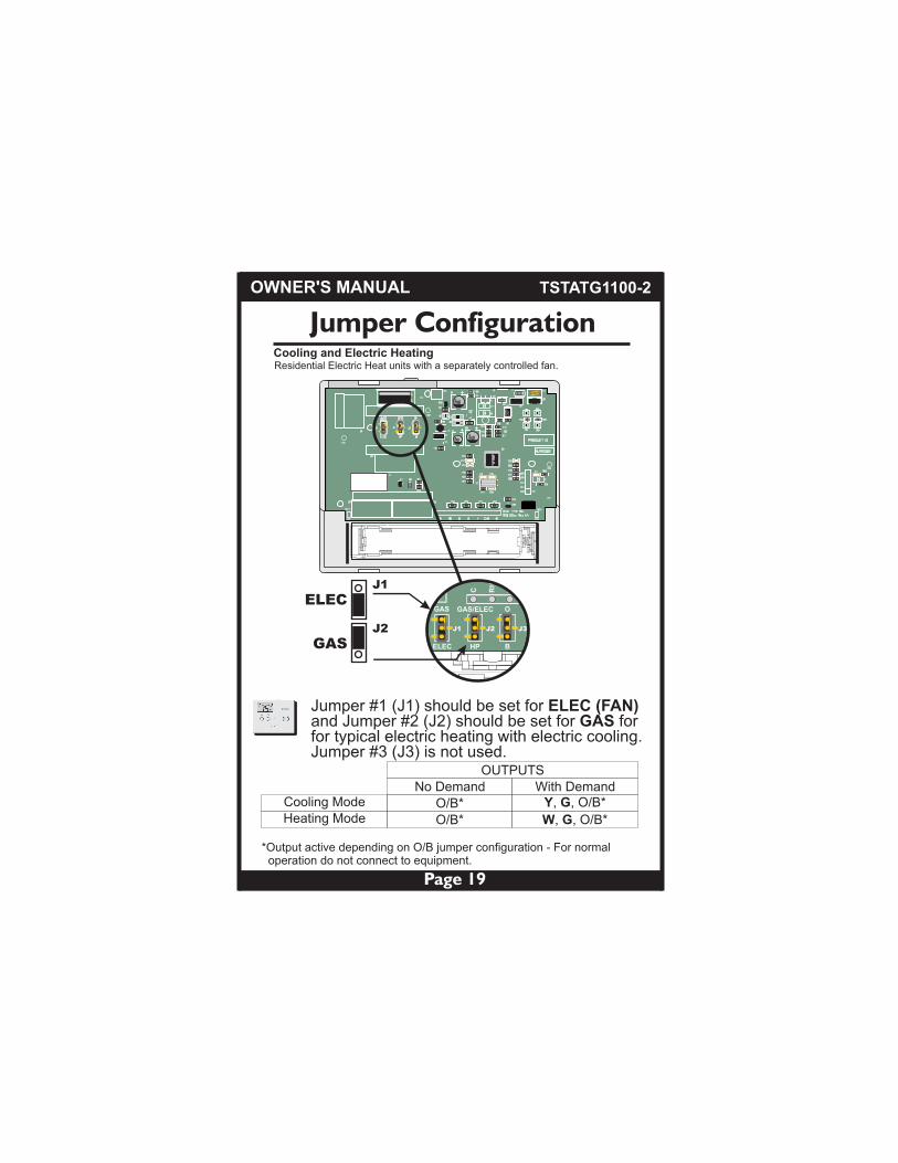
OUTPUTSNo Demand With Demand
Cooling ModeHeating Mode
O/B* Y, G, O/B*
O/B* W, G, O/B*
*Output active depending on O/B jumper configuration - For normal operation do not connect to equipment.
Cooling and Electric HeatingResidential Electric Heat units with a separately controlled fan.
OWNER'S MANUAL
Jumper #1 (J1) should be set for ELEC (FAN) and Jumper #2 (J2) should be set for GAS forfor typical electric heating with electric cooling. Jumper #3 (J3) is not used.
TSTATG1100-2
10
00
JFK
SKD
10
00
JFK
SKD
10
00
JFK
SKD
471
471
471
471
471
471
471 471
471
471
471
471
471 471
471
471
471
471
471
471
ASDF
NN
E A
CP
JA
P4
S2
20
-5N
8 3
D4
471 471 471 471
471
471
471
471
471
471
471
471
ASDF
ASDF
471
ASD
F
GAS
ELEC
GAS/ELEC
HP
O
B
C
RH
Y
J3J2J1
ELEC
GAS
J1
J2

Jumper ConfigurationCooling and Heating - Heat Pump with O reversing valve.Residential Heat Pumps, split systems & package units, with no auxiliary heat.
Page 20
OUTPUTSNo Demand With Demand
Cooling ModeHeating Mode
O Y, G, O
- Y G,
Y active in Heating
OWNER'S MANUAL
Residential Heat Pumps, split systems & package units, with no auxiliary heat.
Jumper #1 (J1) should be set for ELEC (FAN),Jumper #2 (J2) should be set for HP, and Jumper #3 (J3) should be set for O for typical heat pump operation. Note: Thermostat doesnot have Auxiliary Heat / Emergency Heat capability.
TSTATG1100-2
10
00
JFK
SKD
10
00
JFK
SKD
10
00
JFK
SKD
471
471
471
471
471
471
471 471
471
471
471
471
471 471
471
471
471
471
471
471
ASDF
NN
E A
CP
JA
P4
S2
20
-5N
8 3
D4
471 471 471 471
471
471
471
471
471
471
471
471
ASDF
ASDF
471
ASD
F
GAS
ELEC
GAS/ELEC
HP
O
B
C
RH
Y
J3J2J1
ELEC
HP
J1
J2O
J3
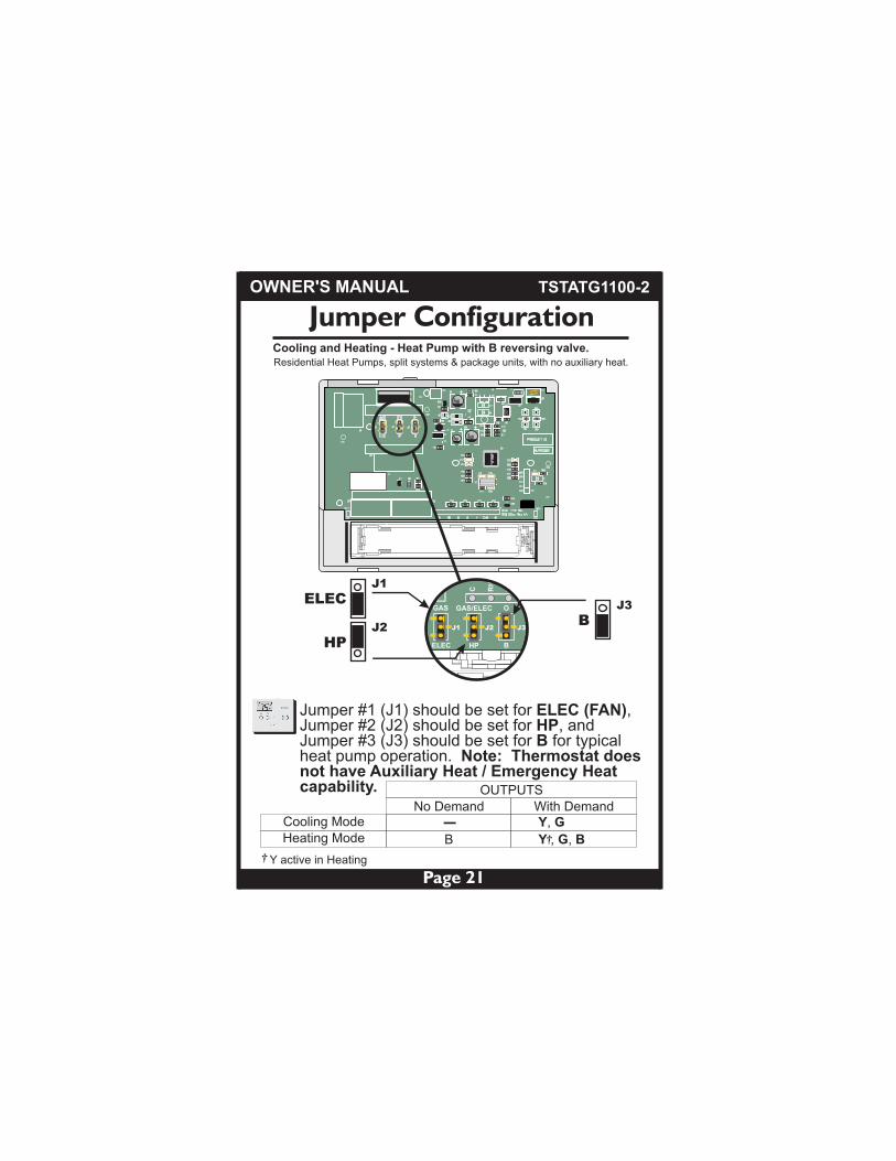
Jumper ConfigurationCooling and Heating - Heat Pump with B reversing valve.Residential Heat Pumps, split systems & package units, with no auxiliary heat.
OUTPUTSNo Demand With Demand
Cooling ModeHeating Mode
Y, G
B Y , G, B
Y active in Heating
Page 21
-
OWNER'S MANUAL
Jumper #1 (J1) should be set for ELEC (FAN),Jumper #2 (J2) should be set for HP, and Jumper #3 (J3) should be set for B for typical heat pump operation. Note: Thermostat doesnot have Auxiliary Heat / Emergency Heat capability.
TSTATG1100-2
10
00
JFK
SKD
10
00
JFK
SKD
10
00
JFK
SKD
471
471
471
471
471
471
471 471
471
471
471
471
471 471
471
471
471
471
471
471
ASDF
NN
E A
CP
JA
P4
S2
20
-5N
8 3
D4
471 471 471 471
471
471
471
471
471
471
471
471
ASDF
ASDF
471
ASD
F
GAS
ELEC
GAS/ELEC
HP
O
B
C
RH
Y
J3J2J1
ELEC
HP
J1
J2B
J3
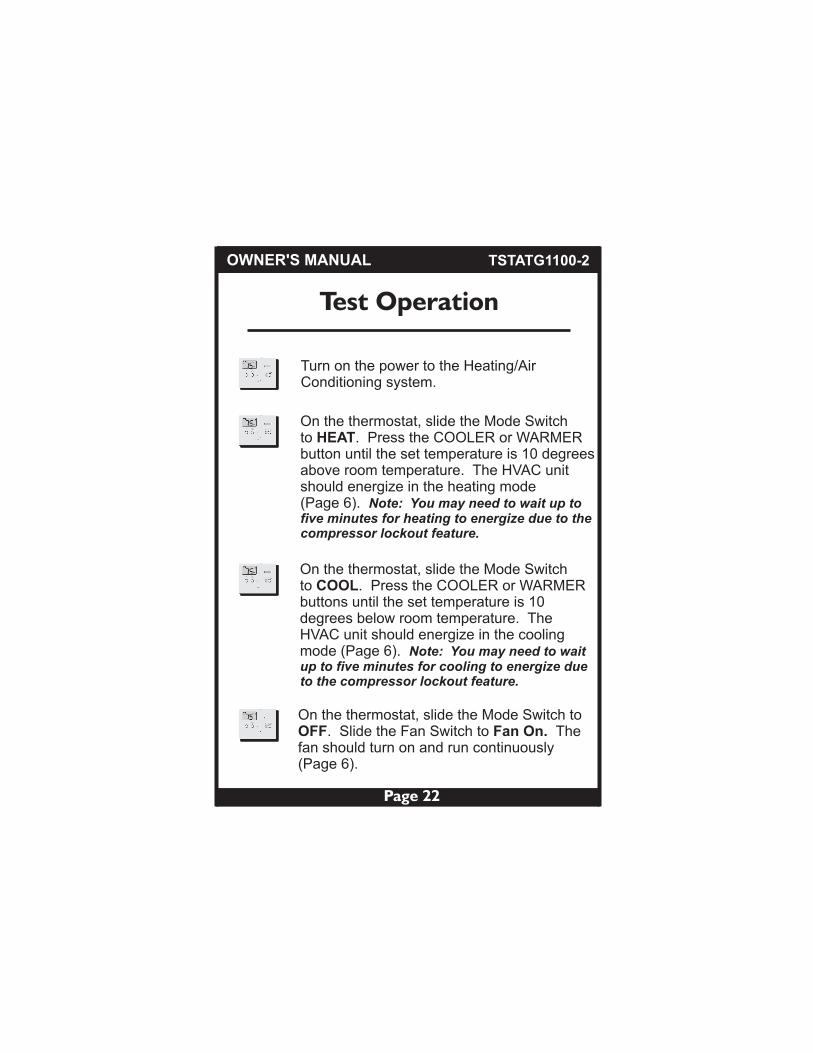
Test Operation
On the thermostat, slide the Mode Switch to HEAT. Press the COOLER or WARMERbutton until the set temperature is 10 degreesabove room temperature. The HVAC unit should energize in the heating mode (Page 6). Note: You may need to wait up tofive minutes for heating to energize due to thecompressor lockout feature.
On the thermostat, slide the Mode Switch to COOL. Press the COOLER or WARMERbuttons until the set temperature is 10 degrees below room temperature. The HVAC unit should energize in the cooling mode (Page 6). Note: You may need to wait up to five minutes for cooling to energize due to the compressor lockout feature.
Turn on the power to the Heating/AirConditioning system.
On the thermostat, slide the Mode Switch to OFF. Slide the Fan Switch to Fan On. The fan should turn on and run continuously (Page 6).
OWNER'S MANUAL
Page 22
TSTATG1100-2

Trouble Shooting
SYMPTOM: The slide switches on the thermostat are very difficult to move.CAUSE: The backplate of the thermostat is screwed too tightly into a wall that is not perfectly flat.REMEDY: Loosen the screws holding the thermostat into the wall.
SYMPTOM: The Air Conditioning does not attempt to turn on.CAUSE: The cooling setpoint is set too high, the Mode Switch is not set for Cool, or the batteries are too weak.REMEDY: Consult the Normal Operation section in this manual to: Lower the cooling setpoint (Page 6). Correct the Mode Switch position (Page 6). Replace the batteries (Page 10).
OWNER'S MANUAL
Page 23
SYMPTOM: The fan does not turn on even though the compressor has energized.CAUSE: The Fan Switch is not completely in the On or Auto position.REMEDY: Slide the Fan Switch firmly into the On or Auto position.
TSTATG1100-2

Trouble Shooting
SYMPTOM: The Heating does not attempt to turn on.CAUSE: The heating setpoint is set too high, the Mode Switch is not set for Heat, or the batteries are too weak.REMEDY: Consult the Normal Operation section in this manual to: Raise the heating setpoint (Page 6). Correct the Mode Switch position (Page 6). Replace the batteries (Page 10).
P/N 88-841Rev. 1
CcFFOR HOME OR OFFICE USE
Tested to Complywith FCC Standards
Battery Stat P/N TSTATG1100-2
4Z95
OWNER'S MANUAL
Page 24
Air Conditioning & Heating
Goodman Manufacturing Company, L.P., reserves the right to discontinue, or change at any time, specifications or designs without notice or without incurring obligations.
Copyright © 2009 • Goodman Manufacturing Company, L.P. • Houston, Texas
TSTATG1100-2
Page 25
OWNER'S MANUAL
Installer Name
Installation Date
Model #
Serial #
LIMITED WARRANTY
Some states and provinces do not allow limitations on how long animplied warranty lasts, so the above limitation may not apply toyou.
GOODMAN SHALL IN NO EVENT BE LIABLE FOR INCIDENTALOR CONSEQUENTIAL DAMAGES, INCLUDING BUT NOT LIMITEDTO EXTRA UTILITY EXPENSES OR DAMAGES TO PROPERTY.Some states and provinces do not allow the exclusion or limitationof incidental or consequential damages, so the above exclusionmay not apply to you.
Goodman is not responsible for:
1. Damage or repairs required as a consequence of faultyinstallation or application.
2. Damage as a result of floods, fires, winds, lightning,accidents, corrosive atmosphere or other conditionsbeyond the control of Goodman.
3. Use of components or accessories not compatible withthis thermostat.
4. Products installed outside the United States or Canada.
5. Damage or repairs required as a result of any improperuse, maintenance, operation or servicing.
6. Failure to start due to interruption and/or inadequateelectrical service.
7. Changes in the appearance of the unit that do not affectits performance.
This warranty gives you specific legal rights, and you may alsohave other rights that may vary from state to state or province toprovince.
This thermostat is warranted by Goodman Manufacturing Company,L.P. (“Goodman”) to be free from defects in materials andworkmanship under normal use and maintenance, as describedbelow:
• The thermostat is warranted for a period of ONE YEAR,
except as provided below.
No warranty continues after the thermostat is removed from thelocation where it was originally installed.
No warranty applies to, and no warranty is offered by Goodman on,any thermostat ordered over the Internet.
The warranty period begins on the date of the original installation. Ifthat date cannot be verified, the warranty period begins twelveweeks from the date of manufacture (as indicated by the first fourdigits of the serial number (yyww) where “yy” inidcates the yearand “ww” indicates the week of manufacture).
As its only responsibility, and your only remedy, Goodman will,without charge, replace any thermostat or thermostat part found tobe defective due to workmanship or materials under normal use andmaintenance. For warranty credit, the defective thermostat orthermostat part must be returned to a Goodman heating and airconditioning products distributor by a state certified or licensedcontractor.
This warranty does not apply to labor, freight, or any other costassociated with the service, repair or operation of the unit.
This warranty is in lieu of all other express warranties. ALL IMPLIEDWARRANTIES, INCLUDING BUT NOT LIMITED TO WARRANTIESOF MERCHANTABILITY AND FITNESS FOR PARTICULARPURPOSE, ARE LIMITED TO THE DURATION OF THIS WARRANTY.
Models:
TSTAT*1100-2, 2100-2, 1152-2, and 2152-2
© 2009 Goodman Manufacturing Company, L.P.
For further information about this warranty, contact Goodman Consumer Affairsat (877) 254-4729 or by mail to 7401 Security Way, Houston, Texas 77040.
*2200C, *3271C, *3272C, *2111, *3272, *3273
* Amana® & Goodman® brand products
TSTATG1100-2