manual indusensor serie eds - micro-epsilon
TRANSCRIPT

EDS-75-SEDS-100-S/FEDS-160-S/FEDS-200-S/F EDS-220-ZEDS-250-S/F
EDS-260-ZEDS-300-S/F/ZEDS-370-Z EDS-400-S/F/ZEDS-500-SEDS-630-S/F
Instruction Manual
induSENSOR, EDS

Long-Stroke sensors, Series EDS
MICRO-EPSILON MESSTECHNIKGmbH & Co. KGKönigbacher Straße 15
94496 Ortenburg / Germany
Tel. +49 (0) 8542 / 168-0Fax +49 (0) 8542 / 168-90e-mail [email protected]
Certified acc. to DIN EN ISO 9001: 2008

induSENSOR, EDS
Contents
1. Safety ........................................................................................................................................ 51.1 Symbols Used ................................................................................................................................................. 51.2 Warnings .......................................................................................................................................................... 51.3 Notes on CE Identification ............................................................................................................................... 61.4 Proper Use ....................................................................................................................................................... 61.5 Proper Environment ......................................................................................................................................... 7
2. Functional Principle, Technical Data ....................................................................................... 82.1 Measuring Principle ......................................................................................................................................... 82.2 Structure .......................................................................................................................................................... 92.3 Technical Data ............................................................................................................................................... 10
3. Delivery ................................................................................................................................... 123.1 Unpacking ...................................................................................................................................................... 123.2 Storage .......................................................................................................................................................... 12
4. Installation and Assembly ...................................................................................................... 134.1 Precautionary Measures ................................................................................................................................ 134.2 Measuring Tube Guide and Fastening .......................................................................................................... 134.3 Sensor Mounting ........................................................................................................................................... 15
4.3.1 Model EDS- ... -S .......................................................................................................................... 154.3.2 Model EDS- ... -F .......................................................................................................................... 224.3.3 Model EDS- ... -Z .......................................................................................................................... 24
4.4 Power Supply and Display/Output Device .................................................................................................... 274.4.1 Model EDS- ... -S .......................................................................................................................... 274.4.2 Model EDS- ... -F .......................................................................................................................... 294.4.3 Model EDS-...-Z ............................................................................................................................ 304.4.4 Load Resistor, Maximum Operating Temperature ....................................................................... 32

induSENSOR, EDS
5. Operation ................................................................................................................................ 33
6. Operation and Maintenance .................................................................................................. 33
7. Warranty .................................................................................................................................. 34
8. Decommissioning, Disposal .................................................................................................. 34
9. Appendix ................................................................................................................................. 35

Page 5
induSENSOR, EDS
1. Safety
The handling of the system assumes knowledge of the instruction manual.
1.1 Symbols Used
The following symbols are used in this instruction manual:
Indicates a hazardous situation which, if not avoided, may result in minor or moder-ate injury.
Indicates a situation which, if not avoided, may lead to property damage.
Indicates a user action.
i Indicates a user tip.
1.2 Warnings
Connect the power supply according to the safety regulations for electrical operating equipment. > Danger of injury
> Damage to or destruction of the sensor
The supply voltage must not exceed specified limits.
> Damage to or destruction of the sensor
Avoid banging and knocking the sensor. > Damage to or destruction of the sensor
Avoid bending the sensor rod or the alu tube. > Damage to or destruction of the sensor
Do not transport the sensor on the sensor rod. > Damage to or destruction of the sensor
Sensor-housing
Alu tube
Sensor rod
Sensorhousing

Page 6
induSENSOR, EDS
1.3 Notes on CE Identification
The following applies to EDS eddy current long stroke displacement sensors: - EU directive 2004/108/EC - EU directive 2011/65/EC, “RoHS” category 9
Products which carry the CE mark satisfy the requirements of the quoted EU directives and the European standards (EN) listed therein. The EC declaration of conformity is kept available according to EC regulation, article 10 by the authorities responsible at
MICRO-EPSILON MESSTECHNIK GmbH & Co. KG Königbacher Straße 15 94496 Ortenburg / Germany
The measuring system is designed for use in industry and satisfies the requirements.
1.4 Proper Use - The sensors are used for
displacement measurement in presses, punches, rolling mills, ect position determination of piston in hydraulic and pneumatic cylinders
- The sensors may only be operated within the limits specified in the technical data, see Chap. 2.3. - Use it in such a way that with malfunctions or total failure of the sensor, persons are not endangered and
machines are not damaged. - Take additional precautions for safety and damage prevention for safety-related applications.

Page 7
induSENSOR, EDS
1.5 Proper Environment - Protection class for sensor
Sensor rod IP 69K Electronics: IP 67 1
- Operating temperature: -40 °C up to +85 °C (-40 up to +185 °F), RL = 500 Ohm - Storage temperature: -40 °C up to +100 °C (-40 up to +212 °F) - Humidity: 5 - 95 % (non-condensing) - Ambient pressure: 450*105 Pa (1 Pa = 1 N/m2) max. 2
1) Models with male plug connection only with gasketed female plug 2) Confined on sensor rod

Page 8
induSENSOR, EDS
2. Functional Principle, Technical Data
2.1 Measuring Principle
The eddy current long stroke displacement sensors transform a linear motion (for example piston position in hydraulic cylinders) into a linear, electrical signal. An aluminium tube, moving concentrically around a sensor rod, is used as target. Energy is transferred from the coil by inducing of eddy currents in the aluminium tube and it is detuned as a result. The integrated, miniaturized electronics convert the tube position into a linear, electrical output signal. The eddy current measuring principle works without contact between moving parts and is therefore free of wear.
0 1/1
4
12
20S
enso
rho
usin
g
Sensor rod
Out
put s
igna
l (m
A)
Measuring range1/2
Alu tube
Fig. 1 Measuring Principle of an eddy current long stroke displacement sensor, alu tube at the start of the measuring range

Page 9
induSENSOR, EDS
2.2 Structure
A coil is mounted inside the sealed rod, protected against environmental influences. The micro-electronics is integrated in the sensor housing. A pressure-proof, stainless steel housing is available as an option. The sen-sors are used for measuring lengths from 100 to 630 mm.
Electrical connection: - Connector 4-pins, type Amphenol C164P compact (Model EDS-...-S...)1
- Connector 7-pins, type Binder 712 (Model EDS-...- S ...7...) - Connector 5-pins, CA02COM-E14S with bayonet connection (Model EDS-...-F...) - Wire, axial (model EDS-...-Z...)
1) Previous model no longer available

Page 10
induSENSOR, EDS
2.3 Technical Data
Model EDS -75
EDS -100
EDS -160
EDS -200
EDS -220
EDS -250
EDS -260
EDS -300
EDS -370
EDS -400
EDS -500
EDS -630
Connections S S, F S, F S, F Z S, F Z S, F, Z Z S, F, Z S S, F
Measuring range mm 75 100 160 200 220 250 260 300 370 400 500 630
Linearity ±0.3 % FSO mm 0.23 0.3 0.48 0.6 0.66 0.75 0.78 0.9 1.1 1.2 1.5 1.89
Resolution 0.05 % FSO mm 0.038 0.05 0.08 0.1 0.11 0.125 0.13 0,15 0.18 0.2 0.25 0.315
Repeatability 0.05 % FSO
Temperature range -40 °C ... +85 °C
Temperature stability ±200 ppm / °C
Frequency response -3 dB 150 Hz, optional up to 300 Hz
Output signal 4 - 20 mA
Output load ≤ 500 Ohm
Power supply 18 - 30 VDC
Current consumption max. 40 mA
Connector
Model S 7-pin connector (sensor cable as an option), options radial or axial output
Model F 5-pin radial bayonet-connector with mating plug
Model Z Wire axial
Pressure resistance 450*105 Pa max. (Sensor rod, flange)1
Protection class Sensor rod: IP 69K, elektronics: IP 67 2
Shock 3 IEC 68-2-29 IEC 68-2-27
40 g, 3000 shocks per axis 100 g radial, 300 g axial
Vibration EC 68-2-65 Hz ... 44 Hz ±2.5 mm 44 Hz ... 500 Hz ±23 g

Page 11
induSENSOR, EDS
Model EDS -75
EDS -100
EDS -160
EDS -200
EDS -220
EDS -250
EDS -260
EDS -300
EDS -370
EDS -400
EDS -500
EDS -630
Connections S S, F S, F S, F Z S, F Z S, F, Z Z S, F, Z S S, F
Sensor material V4A-Steel 1.4571
Tube material AlMgSi, enodized
Sensor weight
EDS-...-S
g
150 170 160 220 --- 250 --- 280 --- 470 560 650
EDS-...-F --- 1260 1270 1300 --- 1320 --- 1350 --- 1560 --- 1750
EDS-...-Z --- --- --- --- 340 --- 370 370 570 570 --- ---
Alu tube
S 20 30 40 40 --- 50 --- 60 --- 90 115 140
F --- 40 40 40 --- 50 --- 60 --- 140 --- 210
Z --- ---- --- --- 46 --- 54 60 92 90 --- ---
FSO = Full Scale Output1) For all models confined on sensor rod 2) With gasketed female plug.3) Half sinusoid 6 ms.

Page 12
induSENSOR, EDS
3. Delivery
3.1 Unpacking Do not take and hold the sensor at the sensor rod. Check for completeness and shipping damage immediately after unpacking.
The delivery of an eddy current long stroke displacement sensor includes:
1 Eddy current long stroke displacement sensor 1 O-ring (mounted on sensor) 1
1 Measuring tube 1 Test report
1 Instruction manual
In case of damage or missing parts, please contact the manufacturer or supplier.
3.2 Storage - Storage temperature: -40 °C up to +100 °C (-40 up to +212 °F) - Humidity: 5 - 95 % (non-condensing) - Atmospheric pressure
1) For sensor models S and F only
Sensorhousing

Page 13
induSENSOR, EDS
4. Installation and Assembly
4.1 Precautionary Measures
The measuring tube must not contact the sensor rod during operation. > Damage to or destruction of the sensor through abrasion is possible.
Do not deform or shorten the measuring tube. > Loss of specified technical data.
Do not crush the O-ring or damage through sharp-edged items. > Loss of functionality
4.2 Measuring Tube Guide and Fastening Mount the measuring tube in the piston bore hold.
The dimensions for the measuring tube are shown, see Fig. 8 et seq. When the piston is moved in the measu-ring tube must not touch the sensor shaft. Observe the measuring tube position at the zero point (= 4 mA output), see Fig. 2 et seq. A slightly eccentric mounting of the measuring tube has no negative influ-ence on the sensor signal.
Mount the measuring tube in the piston by means of pressing or glueing.
Spot clamping is not permissible.
i The specified technical data are valid only if the measuring tube is used supplied by MICRO-EPSILON!

Page 14
induSENSOR, EDS
a a
Fig. 2 Zero point of the measuring tube, EDS- ... -S Fig. 3 Zero point of the measuring tube, EDS- ... -F
a
Measuring range Dimension a
75 15 (0.59)
100 20 (0.79)
160 20 (0.79)
200 20 (0.79)
220 20 (0.79)
250 20 (0.79)
260 20 (0.79)
Fig. 4 Zero point of the measuring tube, EDS- ... -Z 300 20 (0.79)
370 25 (0.98)
Dimensions in mm, not to scale 400 25 (0.98)
500 25 (0.98)
630 25 (0.98)

Page 15
induSENSOR, EDS
4.3 Sensor Mounting
4.3.1 Model EDS- ... -S Mount the sensor in the cylinder with a mounting ring (Appendix), see Fig. 12 and six cylinder head bolts
(M5x10).
Sealing is effected at the sensor shaft by means of an O-ring supplied.
Displacementsensor O-ring Piston
Sensor shaft
CylinderSensor rod
21H
B
Mounting ringM5x10 Alu tube
Fig. 5 Sensor mounting in a hydraulic cylinder, model EDS- ... -S
Sealing O-Ring: 18.5x1.5 Material: Viton
Dimension Fit tolerance µm
21H8 +33 0
Diameter of the borehole: 21H8 dia. Borehole surface: Ra = 0.8 Rmax = 3.2

Page 16
induSENSOR, EDS
Bushing forconnector
15
(.6)
ø34
(1.4
dia
.)
ø31(1.2 dia.)
40 (1.6)
Use a connection piece for moun-ting, see Fig. 6. The bushing must be congruent with the connector for models with radial connector.
Fig. 6 Mounting of an induSENSOR, model EDS- ... -S
Groove
Use an extractor for dismounting, see Fig. 7. Dimensions of the flange groove: 1.5 x 1.5 mm (.06 x .06 “,depth x width).
Fig. 7 Dismounting of an induSENSOR, model EDS- ... -S
Dimensions in mm, not to scale

Page 17
induSENSOR, EDS
Dimensional drawing, model EDS- ... -S
32.5 (1.28)
4 +0.1
(.16 +0.1)8 -0.1
(.32 -0.004)
ø34
-0.1
(1.3
4 -0
.004
dia
.)ø2
1f7
(.83
dia
.)ø1
0 (.
39 d
ia.)
1.5
(.06
)
Sensor rod L
Alu tube I
ø30
(1.1
8 di
a.)
l
L
d
min 30(1.18)
A
B
Fig. 8 induSENSOR with axial connector, model EDS- ... -SA7 - I, measuring range: 75 (2.95) / 100 (3.94) / 160 (6.29) / 200 (7.87) / 250 ( 9.84) / 300 (11.81)
Dimension Fit tolerance µm A B
21f7 -20 -41
EDS-xxx-S-Sx-l 1 31 (1.2) 16 (.63)
EDS-xxx-S-Sx7-l 51 (2.0) 47 (1.85)
Dimensions in mm (inches), not to scale
1) Previous model no longer available.
Measuring range
Sensor rod L Alu tube I Alu tube d
100 (3.93)
140 (5.51)
140 (5.51)
16 (.63)
160 ( 6.29)
200 (7.87)
200 (7.87)
16 (.63)
200 (7.87)
240 (9.45)
240 (9.45)
16 (.63)
250 (9.84)
290 (11.42)
290 (11.42)
16 (.63)
300 (11.81)
340 (13.39)
340 (13.39)
16 (.63)

Page 18
induSENSOR, EDS
13 (
0.51
)A
Fig. 9 induSENSOR with radial connector, model EDS- ... -SR7 - I, measuring range: 75 (2.95) / 100 (3.94) / 160 (6.29) / 200 (7.87) / 250 (9.84) / 300 (11.81)
A
EDS-xxx-S-Sx-I 1 31 (1.2)
EDS-xxx-S-Sx7-I 51 (2.0)
Dimensions in mm, not to scale
1) Previous version no longer available.

Page 19
induSENSOR, EDS
32.5 (1.28)
4 +0.1
(.16 +0.1)
1.5
(.06
)
Sensor rod L
Alu tube I
ø30
(1.1
8 di
a.)
ø12(
.47
dia.
)
d
16 -0,1
(.63 -0.004)
l
L
ø21f
7 (
.83
dia.
)
min 30(1.18) A
B
ø34
-0.1
(1.3
4 -0
.004
dia
.)
Fig. 10 induSENSOR with axial connector, model EDS- ... -SA7 - I, measuring range: 400 (15.74) / 500 (19.69) / 630 (24.80), dimensions in mm (inches), not to scale
Dimension Tolerance µm A B
21f7 -20 -41
EDS-xxx-S-Sx-l 1 31 (2.19)
16 (.63)
EDS-xxx-S-Sx7-l 51 (2.1)
47 (1.85)
Measuring range
Sensor rod Alu tube
L I d
400 (15.74) 450 (17.72) 450 (17.72) 18 (.71)
500 (19.69) 550 (21.65) 550 (21.65) 18 (.71)
630 (24.80) 680 (26.77) 680 (26.77) 18 (.71)1) Previous version no longer available.

Page 20
induSENSOR, EDS
13
(0.5
1)A
Fig. 11 induSENSOR with radial connector, model EDS- ... -SR7 - I, measuring range: 400 (15.74) / 500 (19.69) / 630 (24.80)
A
EDS-xxx-S-Sx-I 1 31 (1.2)
EDS-xxx-S-Sx7-I 51 (2.0)
Dimensions in mm (inches), not to scale
1) Previous version no longer available.

Page 21
induSENSOR, EDS
ø80.0 (ø3.15)
12.0 (.47)
ø55.0 (ø2.17)
30.0 °
1.0
(.04
)
3.95
-0.0
5 (.
16 -0
.002
)
8.0
(.32
)a
b
c
da ø6.2 (ø.24)b ø34.0 +0.05 (ø1.34 +0.002 )
c ø31.0 +0.1 (ø1.22 +0.004)
d ø16.0 (ø.63)
Fig. 12 Mounting ring, model EDS- ... -S, dimensions in mm (inches), not to scale
Page 22
induSENSOR, EDS
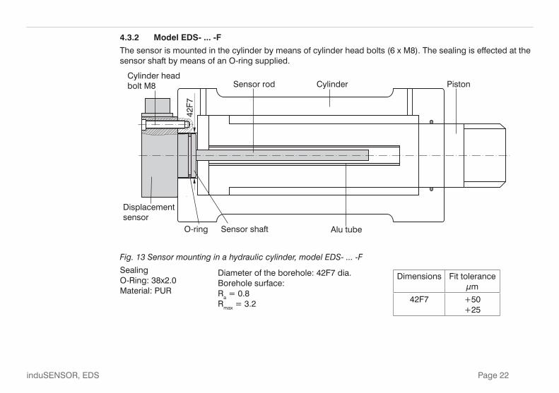
4.3.2 Model EDS- ... -F
The sensor is mounted in the cylinder by means of cylinder head bolts (6 x M8). The sealing is effected at the sensor shaft by means of an O-ring supplied.
Sensor rod Cylinder Piston
Sensor shaft Alu tubeO-ring
Displacementsensor
42F7
Cylinder headbolt M8
Fig. 13 Sensor mounting in a hydraulic cylinder, model EDS- ... -F
Sealing O-Ring: 38x2.0 Material: PUR
Dimensions Fit tolerance µm
42F7 +50 +25
Diameter of the borehole: 42F7 dia. Borehole surface: Ra = 0.8 Rmax = 3.2

Page 23
induSENSOR, EDS
Dimensional drawing, model EDS- ... -F
35.0(1.38)
20.0(0.79)
Alu tube I
Sensor rod L
O-ring groove
18.0
(.7
1)76
.0 (
2.99
)
ø42.
0 -0
.05
(2.9
9 -0
.002
dia
.)
dD
ø29 (1.14 dia)
59 (
2.32
)
ø63.0 (2.48 dia.)ø80.0 (3.15 dia.)
Measuring range
Sensor rod Alu tube
L D I d
100 (3.93) 140 (5.51) 10 (0.39) 140 (5.51) 16 (0.63)
160 (6.29) 200 (7.87) 10 (0.39) 200 (7.78) 16 (0.63)
200 (7.87) 240 (9.45) 10 (0.39) 240 (9.45) 16 (0.63)
250 (9.84) 290 (11.42) 10 (0.39) 290 (11.42) 16 (0.63)
300 (11.81) 340 (13.39) 10 (0.39) 340 (13.39) 16 (0.63)
400 (15.74) 450 (17.72) 12 (0.47) 460 (18.11) 26 (1.02)
630 ( 24.80) 680 (26.77) 12 (0.47) 690 (27.17) 26 (1.02)
Fig. 14 induSENSOR with radial connector, model EDS- ... -F, dimensions in mm (inches), not to scale

Page 24
induSENSOR, EDS
4.3.3 Model EDS- ... -Z
The sensor is fixed in the cylinder with a grub screw and clamped from the back panel. Sealing is effected at the sensor shaft by means of an O-ring.
Feed the connecting wires in able duct outwards and connect them with the mounting plug.
Grub screw Sensor rod Alu tube PistonBack panel
O- ring
Adapter
M12x1 Mounting plug, 4-pin.
48H
8
> 2
5
>18 15
Fig. 15 Sensor mounting in a hydraulic cylinder, model EDS- ... -Z
Dimension Fit tolerance µm
48H8 +39 0
Alu tube must be flush with the piston
Sealing (not included in the delivery) O-Ring: 44.12x2.62 material: Viton Diameter of the bore-hole: 48H8 dia., borehole surface: Ra = 0.8 Rmax = 3.2

Page 25
induSENSOR, EDS
Dimensional drawing, model EDS- ... -Z
Alu tube I
Sensor rod L
33 (1.3)21(0.82)
12 (0.47) 1 x 45 °
M24
x1.5
ø44
-0.1
(1.7
3 -0
.004
dia
.)
ø44
-0.3
(1.7
3 -0
.12
dia.
)ø4
8f7
(1.8
9 di
a.)
d
D
Fig. 16 induSENSOR with axial wires, model EDS- ... -Z, dimensions in mm (inches), not to scale
Measuring range
Sensor rod Alu tube
L D I d
220 (8.66) 252 (9.92) 10 (.39) 250 (9.84 16 (.63)
260 (10.23) 292 (11.50) 10 (.39) 290 (11.42) 16 (.63)
300 (11.81) 341 (13.43) 10 (.39) 340 (13.39) 16 (.63)
370 (14.57) 457 (17.99) 12 (.47) 450 (17.72) 18 (.71)
400 (15.74) 457 (17.99) 12 (.47) 450 (17.72) 18 (.71)
Dimension Fit tolerance µm
48f7 -25 -50

Page 26
induSENSOR, EDS
Use an extractor pipe for dismounting, see Fig. 17.Female thread in the extractor pipe: M24 x 1.5Proceeding:1. Unplug the adapter.2. Release the grub screw3. Screw on the extractor pipe on the sensor shaft and pull out the sensor from the cylinder.
Extractor pipe
1
2 3
Fig. 17 Dismounting of the induSENSOR, model EDS- ... -Z
Page 27
induSENSOR, EDS
4.4 Power Supply and Display/Output Device
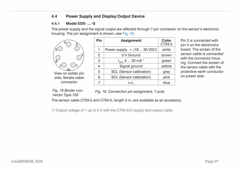
4.4.1 Model EDS- ... -S
The power supply and the signal output are effected through 7-pin connector on the sensor’s electronic housing. The pin assignment is shown, see Fig. 19.
View on solder pin side, female cable
connector
Fig. 18 Binder con-nector Type 702
Pin Assignment Color C703-5
Pin 2 is connected with pin 4 on the electronics board. The screen of the sensor cable is connected with the connector hous-ing. Connect the screen of the sensor cable with the protective earth conductor on power side.
1 Power supply + (18 ... 30 VDC) white
2 0 V Ground brown
3 IOUT 4 ... 20 mA 1 green
4 Signal ground yellow
5 SCL (Sensor calibration) grey
6 SCL (Sensor calibration) pink
7 n.c. blue
Fig. 19 Connection pin assignment, 7-pole
The sensor cable C703-5 and C704-5, length 5 m, are available as an accessory.
1) Output voltage of 1 up to 5 V with the C703-5/U supply and output cable.

Page 28
induSENSOR, EDS
_
+
_
18...30 VDC
23
4
1
UB
A
+
RLIOUT
EDS-...-SRL can be inserted as an option for adap-tation of the power loss to high ambient temperatures, see Chap. 4.4.4.
Fig. 20 Signal monitoring with amperemeter
23
4
1
B
V
18...30 VDC+
+
_
UOUT
U_
RL
IS
EDS-...-SIf the signal is monitored with a voltmeter the load resistor RL is sized to give the de-sired output voltage UOUT.
Formula: UOUT = RL * ISignal
Fig. 21 Signal monitoring with load resistor and voltmeter

Page 29
induSENSOR, EDS
4.4.2 Model EDS- ... -F
Power supply and signal output are effected through the 5-contact connector on the sensor’s electronic housing. The pin assignment is shown, see Fig. 22.
Pin Assignment A 5-pin cable socket for the user-side as-sembly of your own connecting cable is part of the delivery scope.
A Power supply + (18 ... 30 VDC)
B Ground
C 4 ... 20 mA
D Housing Fig. 22 Table connection pin assignment, bayonet connection, view of solder pin side female cable connector
E ---
+
_
+
_
18...30 VDC
IR
UB
A
L
OUT
B
C
A
D
E
EDS-...-FRL can be inserted as an option for adap-tation of the power loss to high ambient temperatures, see Chap. 4.4.4.
Fig. 23 Signal monitoring with ampere-meter
Connector Type CA02COM-G14S The C705-5 sensor cable is available as an accessory.

Page 30
induSENSOR, EDS
+
_
+
_
18...30 VDC
UB
U
VR
L OUT
IS
B
C
A
D
E
EDS-...-F If the signal is monitored with a voltmeter the load resistor RL is dimensioned in ac-cordance with the desired output voltage UOUT.
Formula: UOUT = RL * ISignal
Fig. 24 Signal monitoring with load resis-tor and voltmeter
4.4.3 Model EDS-...-Z
Power supply and signal output are effected through the 4-contact connector on the hydraulic cylinder. The pin assignment is shown, see Fig. 25.
Pin Assignment Color A 4-pin cable socket for the user-side assembly of your own connecting cable is part of the delivery scope.
Fig. 25 Connection pin assignment, view of solder pin side female cable con-nector
1 Signal ground brown
2 Power supply + (18 ... 30 VDC) white
3 Signal (4 ... 20 mA) blue
4 Supply ground black

Page 31
induSENSOR, EDS
EDS-...-ZRL can be inserted as an option for adapta-tion of the power loss to high ambient temperatures, see Chap. 4.4.4.
Fig. 26 Signal monitoring with amperemeter
EDS-...-ZIf the signal is monitored with a voltmeter the load resistor RL is dimensioned in ac-cordance with the desired output voltage UOUT.
Formula: UOUT = RL * ISignal
Fig. 27 Signal monitoring with load resistor and voltmeter

Page 32
induSENSOR, EDS
4.4.4 Load Resistor, Maximum Operating Temperature
The sensors are connected according to the pin assignment shown, see Fig. 18 et seq. (all series). Notice the different criterias:
- RL max = (UB - 10 V) / 20 mA
- RL min = 82.5 * 1/V * UB - 1625 Ohm
- Tmax = 150 °C - 3.3 °C/V * UB + 0.04 °C/W * RL
The maximum load resistor RL is limited by the operating voltage UB.
(U - 10 V)
20 mABR = L max
A small load resistor loads the sensor electronics more thermical. With a maximum operating temperature of 85 °C (+185 °F) the minimum load resistor RL permitted is calculated as:
R = - 1625 Ohm L min82.5 * U
VB
(If the result is negative: RL = 0 Ω)
With a preset load resistor the maximum operating temperature permitted is calculated as:
T = 150 °C - + 0.04 * RL
max3.3 * U
VB
Ohm ; and Tmax ≤ 85 °C
RL = Load resistor UB = Operating voltage Tmax = Maximum operating temperature

Page 33
induSENSOR, EDS
5. OperationThe sensors have no adjustment and setting elements.
After assembly and connection of display/output device the sensor should warm-up 10 minutes to be ready for operation.
Output signal: 4 mA (start of measuring range) up to 20 mA (end of measuring range)
i The sensor is ready for measuring without adjustment. Warm-up time: 10 min. Output signal: 4 ... 20 mA
6. Operation and Maintenance Observe the notes on measuring tube guiding during operation, see Chap. 4.2.
Imperfect measuring tube guiding can lead to increased wear and premature defects.
The warranty and all liability claims are null and void if the device is worked on by unauthorized persons.
Repairs are to be made exclusively by MICRO-EPSILON.

Page 34
induSENSOR, EDS
7. Warranty
All components of the device have been checked and tested for perfect function in the factory.
In the unlikely event that errors should occur despite our thorough quality control, this should be reported immediately to MICRO-EPSILON MESSTECHNIK.
The warranty period lasts 12 months following the day of shipment.
Defective parts, except wear parts, will be repaired or replaced free of charge within this period if you return the device free of cost to MICRO-EPSILON MESSTECHNIK.
This warranty does not apply to damage resulting from abuse of the equipment and devices, from forceful handling or installation of the devices or from repair or modifications performed by third parties.
No other claims, except as warranted, are accepted. The terms of the purchasing contract apply in full.
MICRO-EPSILON will specifically not be responsible for eventual consequential damages.
MICRO-EPSILON always strives to supply the customers with the finest and most advanced equipment. Development and refinement is therefore performed continuously and the right to design changes without prior notice is accordingly reserved.
For translations in other languages, the data and statements in the German language operation manual are to be taken as authoritative.
8. Decommissioning, Disposal Disconnect the power supply and output cable at the sensor respectively the cylinder. Do the disposal according to the legal regulations (see directive 2002/96/EC).

Page 35
induSENSOR, EDS
9. Appendix
Accessories
DD241 PC (10) Digital process readout, power supply: 12 ... 30 VDC, sensor supply: 10 ... 26 VDC
DD245 PC (10) Digital process readout, power supply: 18 ... 30 VDC, sensor supply: 18 VDC+/-10 %, max. 350 mA, digital output: RS422; analog output: 3x programmable, 0 ... 10 V, 2 programmable limit switch; Tara function
DD241 PC (11) Digital process readout, power supply: 12 ... 30 VDC ; sensor supply: 10 ... 26 VDC, max. 85 mA; digital output: RS232; 2 programmable limit switch; Tara function
C704/90-5 Supply and output cable, 90 °-connector, 4-pole, 5 m long, (Model EDS- ... - S ...)
C704-5 Supply and output cable, straight connector, 4-pole, 5 m long, (Model EDS- ... - S ...)
PS2020 Power supply for mounting on DIN rail, output 24 VDC, input 230 VAC, switchable for 110 VAC
C703-5 Supply and output cable, 7-pole, 5 m long, (Model EDS- ... - S ...7...)
C703/90-5 Supply and output cable, 90 °-plug, 7-pole, 5 m long, (Model EDS- ... - S ...7...)
C703-5/U Supply and output cable, 7-pole, 5 m long, voltage output 1 ... 5 VDC, (Model EDS- ... - S ...7...)
C705-5 Supply and output cable, 5-pole, 5 m long, (Model EDS- ... - F)
EDS mounting ring, (Model EDS- ... - S ...)

MICRO-EPSILON MESSTECHNIK GmbH & Co. KG
Königbacher Str. 15 · 94496 Ortenburg / Germany
Tel. +49 (0) 8542 / 168-0 · Fax +49 (0) 8542 / 168-90
[email protected] · www.micro-epsilon.com
X9751051-B081115GBR
*X9751051-B08*
MICRO-EPSILON MESSTECHNIK