manual - la marzocco usa, espresso machines & grinders · operating manual v2.0 - 07/2016...
TRANSCRIPT
manualgb5 & fb80Named for Giovanna Bambi and designed with classic La Marzocco styling and spirit, the GB/5 combines harmonious aesthetics and powerful technological advancements With gracious lines and curves. The GB/5 is an understated companion to any coffee bar, while its unmatched temperature stability provides steady brew water and steam even at the peak of the morning rush.
ENgb5 & fb80
certifications available:
Operating Manual V2.0 - 07/2016MAN.3.1.01
La Marzocco S.r.l.
Via La Torre 14/HLocalità La Torre50038 Scarperia e San Piero (Firenze) - ITALIA
T: +39 055 849 191F: +39 055 849 1990
Chapters1. General Warnings and Safety Specifications
2. Definition of Available Models
3. Installation
4. Machine Operation and Coffee Preparation
5. Dispensing Steam and Hot Water
6. Maintenance and Periodic Cleaning Operations
7. De-commissioning and Demolition
8. Mandatory Maintenance and Check-up Operations
9. Software Programming Guide
page 2
page 4
page 6
page 11
page 14
page 15
page 17
page 18
page 19
EN2
1) This operating manual is an integral and essential part of the product and must be supplied to users. Users are asked to read the enclosed warnings and cautions carefully, as they provide valuable information concerning safety during installation, operation and maintenance. This manual must be kept in a safe place and be available for consultation to new and experienced users alike.2) Ensure product’s integrity by inspecting the packaging, making sure it presents no signs of damage which might have affected the enclosed machine.3) Check the machine’s integrity after having carefully removed the packaging.Note: In case of doubt, do not go on any further and contact your dealer or retailer immediately. They will send out specialized personnel authorized to perform service on the espresso machine.4) Packaging (boxes, plastic bags, foam parts and whatever else) must not be left around within easy reach of children, due to the potential danger it represents, nor be discarded in the environment.5) Check to see that data on the rating
plate corresponds to those of the main electrical supply which the machine will be hooked up to.6) The equipment must be installed to comply with the applicable federal, state or local electrical and plumbing codes.The installation also must comply to the manufacturer’s instructions, and must be performed by qualified and authorized personnel.7) Incorrect installation may cause injury/damages to people, animals or objects, for which the manufacturer shall not be held responsible.8) Safe electrical operation of this device will be achieved only when the connection to the power outlet has been completed correctly and in observance of all local, national, and international electrical codes and safety regulations, and particularly by grounding the unit. Make sure grounding has been done properly as it represents a fundamental safety requirement. Ensure qualified personnel check such connection.9) Furthermore, you must ensure that the capacity of the available electrical system is suitable for the maximum power consumption indicated on the espresso machine.10) We do not recommend using adapters, multiple plugs and/or extension cords.
If you cannot avoid using them, make sure that they are exclusively of the kind which conforms to local, national, and international electrical codes and safety regulations, being careful not to exceed the power and current ratings indicated on such adapters and extension cords.11) This device must be used exclusively for the functions it has been designed and built for. Any other application is inappropriate and dangerous.The manufacturer shall not be held responsible for any damages caused by improper and/or irrational use.This machine should not be installed in kitchens.12) Using any electrical device requires that certain fundamental rules be observed. In particular:• do not touch the device with wet or
humid hands and feet;• do not use the device while having no
shoes on your feet;• do not use extension cords in bath or
shower rooms;• do not unplug the device from the
power outlet by pulling on the power supply cable;
• do not expose the device to atmospheric agents (rain, sun, etc.);
• do not allow children or untrained people to use this device;
1. General Warnings and Safety SpecificationsWARNING
THIS MACHINE IS FOR PROFESSIONAL USE ONLY AND SHOULD BE INSTALLED IN LOCATIONS WHERE ITS
USE AND MAINTENANCE IS RESTRICTED TO TRAINED PERSONNEL. CHILDREN ARE FORBIDDEN TO OPERATE
OR PLAY WITH THE MACHINE.
EN 3
• do not clean the control panel with a wet cloth since it is not watertight.
13) Before carrying out any maintenance and/or cleaning operations, turn the main switch, which is located on the front left of the machine, to the “0” or OFF position, and disconnect the machine from the electrical network by unplugging the cord or by switching off the relevant circuit breaker. For any cleaning operation, follow exclusively the instructions contained in this manual.14) When the machine is operating in a faulty manner or breaks down, disconnect it from the electrical network (as described in the preceding point) and close the water supply valve. Do not attempt to repair it. Contact a qualified and authorized professional to perform any repair. Any repairs must be performed exclusively by the manufacturer or by an authorized agent using only original parts. Non compliance with the above could compromise the safe operation of the machine.15) You should plan to make use of an omnipolar connector during installation, as required by local, national, and international electrical codes and regulations.16) In order to avoid dangerous over-heating problems, it is recommended that the power supply cable be fully unfurled.
17) Do not obstruct air intake and exhaust grilles and, in particular, do not cover the cup warmer tray with cloths or other items.18) The machine’s power supply cable must not be replaced by users. In case the power supply cable becomes damaged, shut off the machine and disconnect the machine from the electrical network by switching off the relevant circuit breaker and close off the water supply; to replace the power supply cord, contact qualified professionals exclusively.
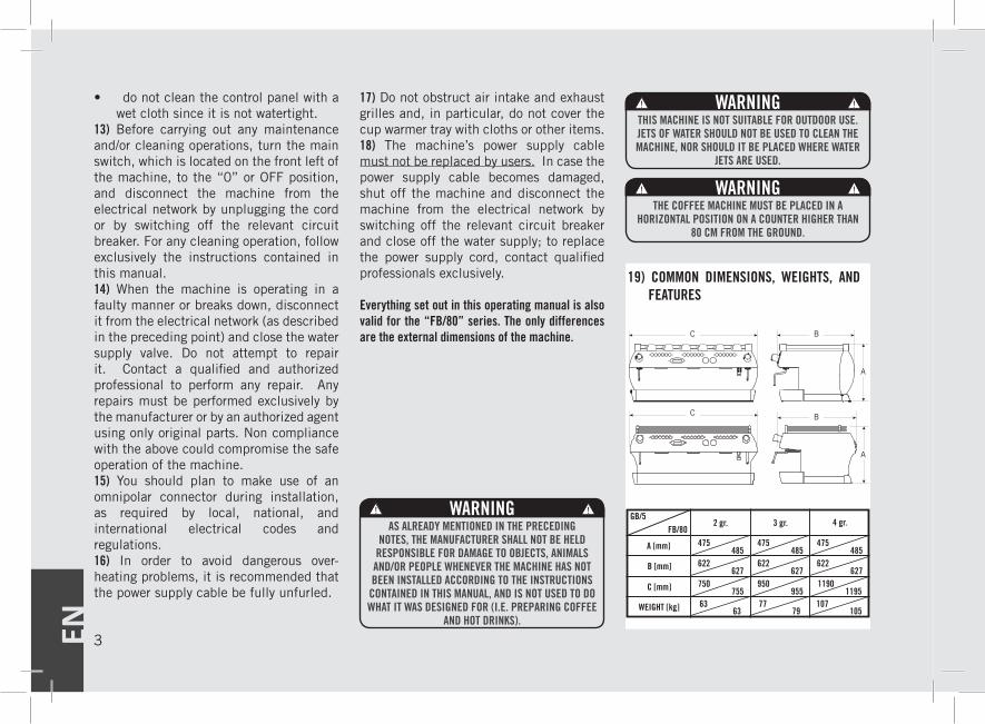
Everything set out in this operating manual is also valid for the “FB/80” series. The only differences are the external dimensions of the machine.
AV
EE
MP
12 1356
9 1 8 4 2 3 7 10 8 911
15
14a 14b
19) COMMON DIMENSIONS, WEIGHTS, AND FEATURES
77 107
GB/5FB/80
2 gr. 3 gr. 4 gr.
A [mm]
B [mm]
C [mm]
WEIGHT [kg]
475485
63
475485
475485
622627
750755
950955
11901195
622627
622627
63 79 105
A
A
B
B
C
C
WARNINGAS ALREADY MENTIONED IN THE PRECEDING
NOTES, THE MANUFACTURER SHALL NOT BE HELD RESPONSIBLE FOR DAMAGE TO OBJECTS, ANIMALS
AND/OR PEOPLE WHENEVER THE MACHINE HAS NOT BEEN INSTALLED ACCORDING TO THE INSTRUCTIONS CONTAINED IN THIS MANUAL, AND IS NOT USED TO DO WHAT IT WAS DESIGNED FOR (I.E. PREPARING COFFEE
AND HOT DRINKS).
WARNINGTHIS MACHINE IS NOT SUITABLE FOR OUTDOOR USE. JETS OF WATER SHOULD NOT BE USED TO CLEAN THE MACHINE, NOR SHOULD IT BE PLACED WHERE WATER
JETS ARE USED.
WARNINGTHE COFFEE MACHINE MUST BE PLACED IN A
HORIZONTAL POSITION ON A COUNTER HIGHER THAN 80 CM FROM THE GROUND.
EN4
2. Definition of Available Models
AV
EE
MP
12 1356
9 1 8 4 2 3 7 10 8 911
15
14a 14b
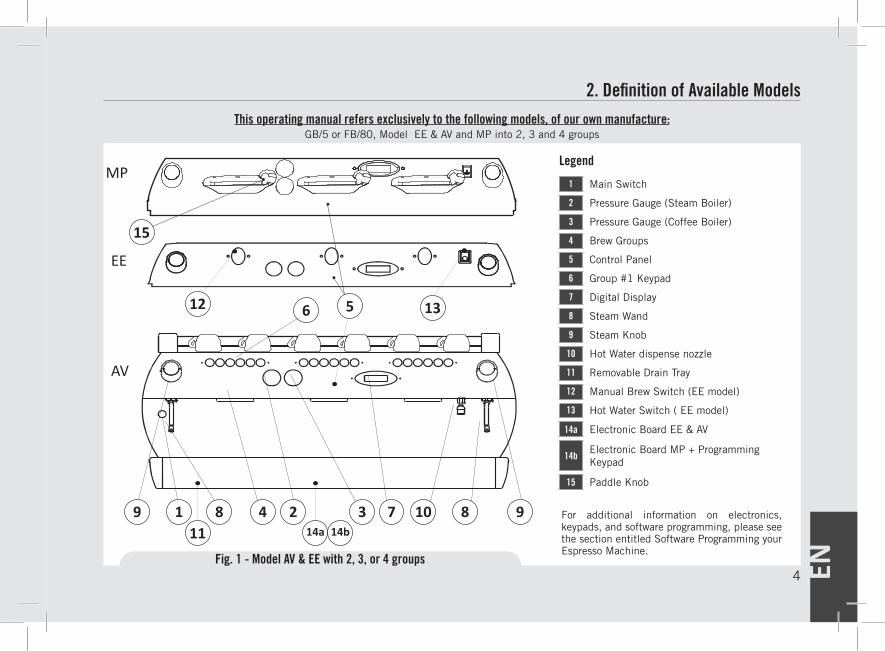
This operating manual refers exclusively to the following models, of our own manufacture:GB/5 or FB/80, Model EE & AV and MP into 2, 3 and 4 groups
Fig. 1 - Model AV & EE with 2, 3, or 4 groups
For additional information on electronics, keypads, and software programming, please see the section entitled Software Programming your Espresso Machine.
Legend
1 Main Switch
2 Pressure Gauge (Steam Boiler)
3 Pressure Gauge (Coffee Boiler)
4 Brew Groups
5 Control Panel
6 Group #1 Keypad
7 Digital Display
8 Steam Wand
9 Steam Knob
10 Hot Water dispense nozzle
11 Removable Drain Tray
12 Manual Brew Switch (EE model)
13 Hot Water Switch ( EE model)
14a Electronic Board EE & AV
14bElectronic Board MP + Programming Keypad
15 Paddle Knob
EN 5
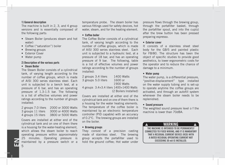
1) General descriptionThe machine is built in 2, 3, and 4 group versions and is essentially composed of the following parts:
• Steam Boiler (produces steam and hot water)
• Coffee (“saturation”) boiler• Brewing groups• Exterior Cover• Water pump
2) Description of the various parts• Steam BoilerThe Steam Boiler consists of a cylindrical tank, of varying length according to the number of coffee groups, which is made of AISI 300 series stainless steel. Each unit is subjected to a bench test, at a pressure of 6 bar, and has an operating pressure of 1.3-1.5 bar. The following is a list of effective volumes and power ratings according to the number of groups installed:
2 groups 7.0 liters 2000 or 3000 Watts3 groups 11 liters 3000 or 4000 Watts4 groups 15 liters 3800 or 5000 Watts
Covers are installed at either end of the cylindrical tank and on one of them there is a housing for the water-heating element, which allows the steam boiler to reach operating pressure within approximately 25 minutes. Operating pressure is maintained by a pressure switch or a
temperature probe. The steam boiler has various fittings used for safety devices, hot water, steam, and for the heating element.
• Coffee boilerThe Coffee Boiler consists of a cylindrical tank, of varying length according to the number of coffee groups, which is made of AISI 300 series stainless steel. Each unit is subjected to a hydraulic test, at a pressure of 18 bar, and has an operating pressure of 9 bar. The following, table is a list of effective volumes and power ratings according to the number of groups installed:
2 groups 3.4 liters 1400 Watts3 groups 5.0 liters 1600 or 1900 Watts4 groups 3.4+3.4 liters 1400+1400 Watts (2 Boilers Installed)
Covers are installed at either end of the cylindrical tank and on one of them there is a housing for the water heating elements. The temperature of the coffee boiler is maintained by an electronic temperature controller (PID capable) with an accuracy of 0.2°C. The brewing groups are installed on the boiler.
• Brewing groupsThey consist of a precision casting made of stainless steel. The brewing group accepts the portafilter used to hold the ground coffee; Hot water under
pressure flows through the brewing group, through the portafilter basket, through the portafilter spout, and into the cup(s) after the brew button has been pressed preparing espresso.
• Exterior coverIt consists of a stainless sheet steel body for the GB/5 and painted plastic for FB/80. The structure has been the object of specific studies to provide good aesthetics, to lower ergonometric costs for the operator and to reduce the chance of damage to a minimum.
• Water pumpThe water pump, is a differential pressure, “positive-displacement” type installed on the water supply tubing and is set-up to operate anytime the coffee groups are activated, and through an autofill system whenever the steam boiler needs to be replenished.
• Sound pressureThe weighted sound pressure level o f the machine is lower than 70dBA.
WARNINGTHE MACHINE IS INTENDED TO BE PERMANENTLY
CONNECTED TO FIXED WIRING, AND IT IS MANDATORY THAT A RESIDUAL CURRENT DEVICE (RCD) WITH A RATED RESIDUAL OPERATING CURRENT NOT
EXCEEDING 30 mA IS INSTALLED.
EN6
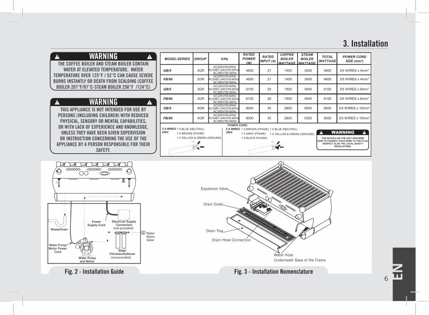
3. Installation
8000 35 2800 5000 8000 3/5 WIRES x 10mm²
3 X WIRES220V
THE DETAILS ON THE LEFT DESCRIBEHOW TO CONNECT EACH WIRE TO THE PLUG.
RESPECT ALSO THE LOCAL SAFETYREGULATIONS.
MODEL/SERIES GROUP V/HzRATED POWER
(W)
RATED INPUT (A)
COFFEE BOILER
WATTAGE
STEAM BOILER
WATTAGE
TOTAL WATTAGE
POWER CORD SIZE (mm²)
GB/5 2GR 4600 21 1400 3000 4600 3/5 WIRES x 4mm²
FB/80 2GR 4600 21 1400 3000 4600 3/5 WIRES x 4mm²
GB/5 3GR 6100 28 1900 4000 6100 3/5 WIRES x 6mm²
FB/80 3GR 6100 28 1900 4000 6100 3/5 WIRES x 6mm²
GB/5 4GR 8000 35 2800 5000 8000 3/5 WIRES x 10mm²
FB/80 4GR
LE FIGURE AFFIANCO DESCRIVONO COMECOLLEGARE OGNI FILO ALLA SPINA.
RISPETTARE ANCHE LE NORME FEDERALI, STATALI O LOCALI VIGENTI.
MODELLO/SERIE GRUPPO V/HzPOTENZANOMINALE
(W)
INPUTNOMINALE
(A)
POTENZACALDAIACAFFE’
POTENZACALDAIAVAPORE
POTENZATOTALE
DIMENSIONE CAVOALIMENTAZIONEELETTRICA (mm²)
GB/5 2GRAC220V/50-60Hz
AC208V-240V/50-60Hz 4600 21 1400 3000 4600 3/5 FILI x 4mm²
FB/80 2GR 4600 21 1400 3000 4600 3/5 FILI x 4mm²
GB/5 3GR 6100 28 1900 4000 6100 3/5 FILI x 6mm²
FB/80 3GR 6100 28 1900 4000 6100 3/5 FILI x 6mm²
GB/5 4GR 8000 35 2800 5000 8000 3/5 FILI x 10mm²
FB/80 4GR 8000 35 2800 5000 8000 3/5 FILI x 10mm²
3 X FILI220V ATTENZIONE
1 X BLU (NEUTRO)1 X MARRONE (FASE) 1 X GIALLO & VERDE (TERRA)
CAVO ALIMENTAZIONE ELETTRICA:5 X FILI380V
1 X MARRONE (FASE)1 X GRIGIO (FASE)1 X NERO (FASE)
1 X BLU (NEUTRO)
1 X GIALLO & VERDE (TERRA)
POWER CORD:1 X BLUE (NEUTRAL)1 X BROWN (PHASE) 1 X YELLOW & GREEN (GROUND)
5 X WIRES380V
1 X BROWN (PHASE)1 X GRAY (PHASE)1 X BLACK (PHASE)
1 X BLUE (NEUTRAL)
1 X YELLOW & GREEN (GROUND)
AC380V/50-60Hz AC220V/50-60Hz
AC208V-240V/50-60Hz AC380V/50-60Hz AC220V/50-60Hz
AC208V-240V/50-60Hz AC380V/50-60Hz AC220V/50-60Hz
AC208V-240V/50-60Hz AC380V/50-60Hz AC220V/50-60Hz
AC208V-240V/50-60Hz AC380V/50-60Hz AC220V/50-60Hz
AC208V-240V/50-60Hz AC380V/50-60Hz
AC220V/50-60Hz AC208V-240V/50-60Hz
AC380V/50-60Hz AC220V/50-60Hz
AC208V-240V/50-60Hz AC380V/50-60Hz AC220V/50-60Hz
AC208V-240V/50-60Hz AC380V/50-60Hz AC220V/50-60Hz
AC208V-240V/50-60Hz AC380V/50-60Hz AC220V/50-60Hz
AC208V-240V/50-60Hz AC380V/50-60Hz AC220V/50-60Hz
AC208V-240V/50-60Hz AC380V/50-60Hz
(not provided)
(not provided)
Water MainsValve
X
(not provided)
(not provided)
Water MainsValve
X
Water HoseUnderneath Base of the Frame
Fig. 3 - Installation NomenclatureFig. 2 - Installation Guide
Drain Hose Connection
Expansion Valve
Drain Grate
Drain Tray
WARNINGTHIS APPLIANCE IS NOT INTENDED FOR USE BY
PERSONS (INCLUDING CHILDREN) WITH REDUCED PHYSICAL, SENSORY OR MENTAL CAPABILITIES,
OR WITH LACK OF EXPERIENCE AND KNOWLEDGE, UNLESS THEY HAVE BEEN GIVEN SUPERVISION
OR INSTRUCTION CONCERNING THE USE OF THE APPLIANCE BY A PERSON RESPONSIBLE FOR THEIR
SAFETY.
WARNINGTHE COFFEE BOILER AND STEAM BOILER CONTAIN
WATER AT ELEVATED TEMPERATURE. WATER TEMPERATURE OVER 125°F / 52°C CAN CAUSE SEVERE BURNS INSTANTLY OR DEATH FROM SCALDING (COFFEE
BOILER 207°F/97°C-STEAM BOILER 256°F /124°C)
EN 7
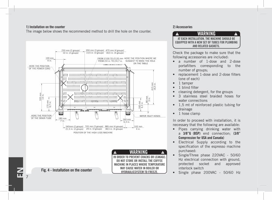
2) Accessories
Check the package to make sure that the following accessories are included:• a number of 1-dose and 2-dose
portafilters corresponding to the number of groups;
• replacement 1-dose and 2-dose filters (one of each)
• 1 tamper• 1 blind filter• cleaning detergent, for the groups• 3 stainless steel braided hoses for
water connections• 1,5 mt of reinforced plastic tubing for
drainage• 1 hose clamp
In order to proceed with installation, it is necessary that the following are available:• Pipes carrying drinking water with
a 3/8”G (BSP) end connection; (3/8” Compression for USA and Canada)
• Electrical Supply according to the specification of the espresso machine purchased:
• Single/Three phase 220VAC - 50/60 Hz electrical connection with ground, protected socket and approved interlock switch
• Single phase 200VAC - 50/60 Hz
100 mm4 in.
HERE THE POSITION OF THE POWER CORD
33
5 m
m1
3 in
.
17
0 m
m6
,7 in
.
180 mm7 in.
HERE THE POSITIONOF THE DRAIN TUBE 160 mm
6,3 in.
16
0 m
m6
,3 in
.
WATER INLET HOSES
102 mm4 in.
80
mm
3 in
.4
15
mm
16
,5 in
.
POSITION OF THE HIGH LEGS MACHINE
545mm (2 groups)21,5 in. (2 groups)
745 mm (3 groups)29 in. (3 groups)
985 mm (4 groups)38,5 in. (4 groups)
FROM ∅100 TO ∅120 mmFROM ∅4 in. TO ∅4,7 in.
HERE THE POSITION WHERE WE SUGGEST TO MAKE THE HOLE
ON THE TABLE
250 mm (2 groups)10 in. (2 groups)
350 mm (3 groups)13,5 in. (3 groups)
470 mm (4 groups)18,5 in. (4 groups)
1) Installation on the counter The image below shows the recommended method to drill the hole on the counter.
Fig. 4 - Installation on the counter
WARNINGIN ORDER TO PREVENT CRACKS OR LEAKAGE:
DO NOT STORE OR INSTALL THE COFFEE MACHINE IN PLACES WHERE TEMPERATURE
MAY CAUSE WATER IN BOILER OR HYDRAULICSYSTEM TO FREEZE.
WARNINGAT EACH INSTALLATION, THE MACHINE SHOULD BE
EQUIPPED WITH A NEW SET OF TUBES FOR PLUMBING AND RELATED GASKETS.
EN8
electrical connection with ground, protected socket and approved interlock switch
• Three-phase, 380VAC - 50 Hz electrical connection with neutral + ground, near the bench on which the machine is installed and terminating in a suitable protected fivepole socket equipped with an approved interlock switch
• Waste water drain system
Note:• The drinking water mains valve and
the circuit breakers for the electrical system need to be located in the most convenient position for the operator to access them easily and quickly.
• The machine should be placed on a flat counter and must be placed in settings with the following temperatures:
Minimum room temperature: 5°C/41°F Maximum room temperature:
32°C/89°F• If the machine has been temporarily
housed in settings with a room temperature of less than 0°C/32°F, please contact a service technician prior to use.
• Water pressure supply must be between 2 and 6 bar.
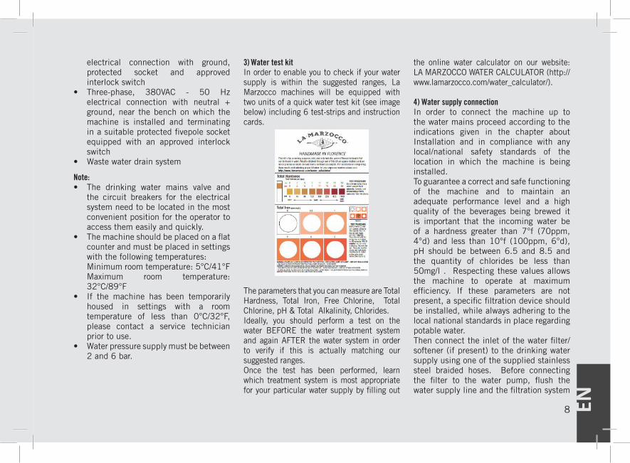
3) Water test kitIn order to enable you to check if your water supply is within the suggested ranges, La Marzocco machines will be equipped with two units of a quick water test kit (see image below) including 6 test-strips and instruction cards.
The parameters that you can measure are Total Hardness, Total Iron, Free Chlorine, Total Chlorine, pH & Total Alkalinity, Chlorides.Ideally, you should perform a test on the water BEFORE the water treatment system and again AFTER the water system in order to verify if this is actually matching our suggested ranges. Once the test has been performed, learn which treatment system is most appropriate for your particular water supply by filling out
the online water calculator on our website: LA MARZOCCO WATER CALCULATOR (http://www.lamarzocco.com/water_calculator/).
4) Water supply connectionIn order to connect the machine up to the water mains proceed according to the indications given in the chapter about Installation and in compliance with any local/national safety standards of the location in which the machine is being installed.To guarantee a correct and safe functioning of the machine and to maintain an adequate performance level and a high quality of the beverages being brewed it is important that the incoming water be of a hardness greater than 7°f (70ppm, 4°d) and less than 10°f (100ppm, 6°d), pH should be between 6.5 and 8.5 and the quantity of chlorides be less than 50mg/l . Respecting these values allows the machine to operate at maximum efficiency. If these parameters are not present, a specific filtration device should be installed, while always adhering to the local national standards in place regarding potable water.Then connect the inlet of the water filter/softener (if present) to the drinking water supply using one of the supplied stainless steel braided hoses. Before connecting the filter to the water pump, flush the water supply line and the filtration system
EN 9
in order to eliminate any residual particles which could otherwise get stuck in taps or valves thus preventing them from working properly. Connect the water supply connection of the espresso machine to the water pump outlet using one of the supplied stainless steel braided hoses. Then connect the water pump inlet to the water filter/softener outlet (if present).
Note: The water pump is a differential pressure volumetric pump and has been designed to be used exclusively with cold water. Make sure that water is always present while the pump is operating, otherwise air can be introduced into the brew boiler causing an undesireable condition and the pump can be damaged.
5) Electrical connections
a) Power supply cord• This is the main power supply cable that provides power to the entire espresso machine. There are different types of cable based upon the electrical requirements of
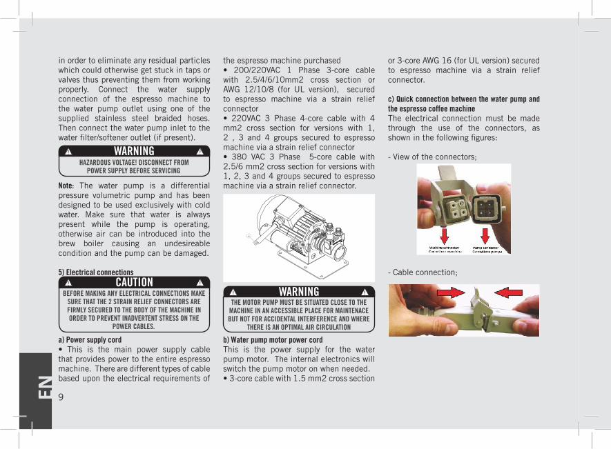
the espresso machine purchased• 200/220VAC 1 Phase 3-core cable with 2.5/4/6/10mm2 cross section or AWG 12/10/8 (for UL version), secured to espresso machine via a strain relief connector• 220VAC 3 Phase 4-core cable with 4 mm2 cross section for versions with 1, 2 , 3 and 4 groups secured to espresso machine via a strain relief connector• 380 VAC 3 Phase 5-core cable with 2.5/6 mm2 cross section for versions with 1, 2, 3 and 4 groups secured to espresso machine via a strain relief connector.
b) Water pump motor power cordThis is the power supply for the water pump motor. The internal electronics will switch the pump motor on when needed.• 3-core cable with 1.5 mm2 cross section
or 3-core AWG 16 (for UL version) secured to espresso machine via a strain relief connector.
c) Quick connection between the water pump and the espresso coffee machineThe electrical connection must be made through the use of the connectors, as shown in the following figures:
- View of the connectors;
- Cable connection;
THE MOTOR PUMP MUST BE SITUATEDCLOSE TO THE MACHINE IN AN ACCESSIBLE
PLACE FOR MAINTENACE BUT NOT FORACCIDENTAL INTERFERENCE AND WHERETHERE IS AN OPTIMAL AIR CIRCULATION
WARNINGHAZARDOUS VOLTAGE! DISCONNECT FROM
POWER SUPPLY BEFORE SERVICING
CAUTIONBEFORE MAKING ANY ELECTRICAL CONNECTIONS MAKE
SURE THAT THE 2 STRAIN RELIEF CONNECTORS ARE FIRMLY SECURED TO THE BODY OF THE MACHINE IN ORDER TO PREVENT INADVERTENT STRESS ON THE
POWER CABLES.
WARNINGTHE MOTOR PUMP MUST BE SITUATED CLOSE TO THE
MACHINE IN AN ACCESSIBLE PLACE FOR MAINTENACE BUT NOT FOR ACCIDENTAL INTERFERENCE AND WHERE
THERE IS AN OPTIMAL AIR CIRCULATION
EN10
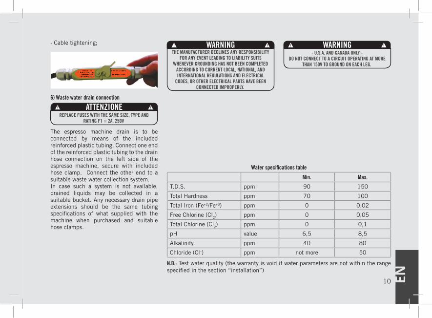
- Cable tightening;
6) Waste water drain connection
The espresso machine drain is to be connected by means of the included reinforced plastic tubing. Connect one end of the reinforced plastic tubing to the drain hose connection on the left side of the espresso machine, secure with included hose clamp. Connect the other end to a suitable waste water collection system. In case such a system is not available, drained liquids may be collected in a suitable bucket. Any necessary drain pipe extensions should be the same tubing specifications of what supplied with the machine when purchased and suitable hose clamps.
WARNINGTHE MANUFACTURER DECLINES ANY RESPONSIBILITY
FOR ANY EVENT LEADING TO LIABILITY SUITS WHENEVER GROUNDING HAS NOT BEEN COMPLETED
ACCORDING TO CURRENT LOCAL, NATIONAL, AND INTERNATIONAL REGULATIONS AND ELECTRICAL
CODES, OR OTHER ELECTRICAL PARTS HAVE BEEN CONNECTED IMPROPERLY.
WARNING- U.S.A. AND CANADA ONLY -
DO NOT CONNECT TO A CIRCUIT OPERATING AT MORE THAN 150V TO GROUND ON EACH LEG.
ATTENZIONEREPLACE FUSES WITH THE SAME SIZE, TYPE AND
RATING F1 = 2A, 250V
Water specifications table
Min. Max.
T.D.S. ppm 90 150
Total Hardness ppm 70 100
Total Iron (Fe+2/Fe+3) ppm 0 0,02
Free Chlorine (Cl2) ppm 0 0,05
Total Chlorine (Cl2) ppm 0 0,1
pH value 6,5 8,5
Alkalinity ppm 40 80
Chloride (Cl–) ppm not more 50
N.B.: Test water quality (the warranty is void if water parameters are not within the range specified in the section “installation”)
EN 11
4. Machine Operation and Coffee Preparation1) Starting the espresso machine
a) Filling the boilers with waterOnce the installation procedures have been completed, it is necessary to fill the boiler tanks with water. Complete the following procedure to properly fill the boiler tanks:
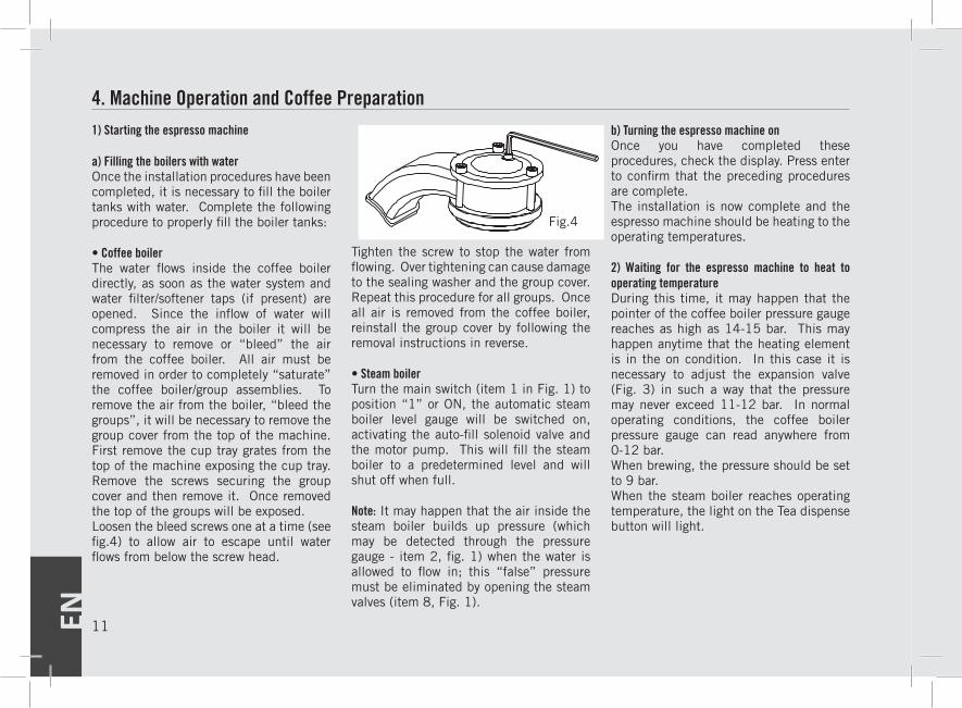
• Coffee boilerThe water flows inside the coffee boiler directly, as soon as the water system and water filter/softener taps (if present) are opened. Since the inflow of water will compress the air in the boiler it will be necessary to remove or “bleed” the air from the coffee boiler. All air must be removed in order to completely “saturate” the coffee boiler/group assemblies. To remove the air from the boiler, “bleed the groups”, it will be necessary to remove the group cover from the top of the machine. First remove the cup tray grates from the top of the machine exposing the cup tray. Remove the screws securing the group cover and then remove it. Once removed the top of the groups will be exposed. Loosen the bleed screws one at a time (see fig.4) to allow air to escape until water flows from below the screw head.
Tighten the screw to stop the water from flowing. Over tightening can cause damage to the sealing washer and the group cover. Repeat this procedure for all groups. Once all air is removed from the coffee boiler, reinstall the group cover by following the removal instructions in reverse.
• Steam boilerTurn the main switch (item 1 in Fig. 1) to position “1” or ON, the automatic steam boiler level gauge will be switched on, activating the auto-fill solenoid valve and the motor pump. This will fill the steam boiler to a predetermined level and will shut off when full.
Note: It may happen that the air inside the steam boiler builds up pressure (which may be detected through the pressure gauge - item 2, fig. 1) when the water is allowed to flow in; this “false” pressure must be eliminated by opening the steam valves (item 8, Fig. 1).
b) Turning the espresso machine onOnce you have completed these procedures, check the display. Press enter to confirm that the preceding procedures are complete.The installation is now complete and the espresso machine should be heating to the operating temperatures.
2) Waiting for the espresso machine to heat to operating temperatureDuring this time, it may happen that the pointer of the coffee boiler pressure gauge reaches as high as 14-15 bar. This may happen anytime that the heating element is in the on condition. In this case it is necessary to adjust the expansion valve (Fig. 3) in such a way that the pressure may never exceed 11-12 bar. In normal operating conditions, the coffee boiler pressure gauge can read anywhere from 0-12 bar. When brewing, the pressure should be set to 9 bar.When the steam boiler reaches operating temperature, the light on the Tea dispense button will light.
Fig.4
EN12
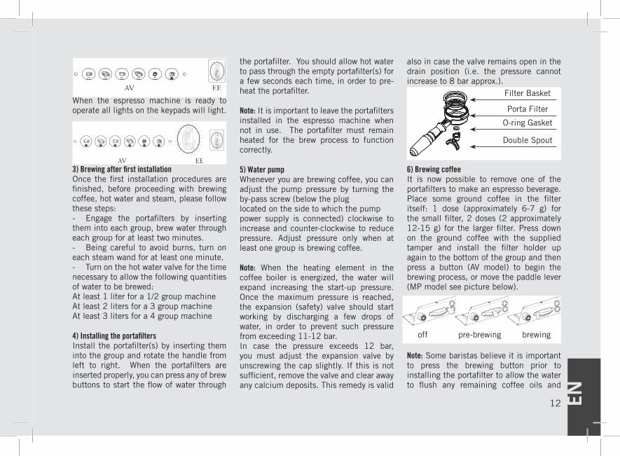
When the espresso machine is ready to operate all lights on the keypads will light.
3) Brewing after first installationOnce the first installation procedures are finished, before proceeding with brewing coffee, hot water and steam, please follow these steps:- Engage the portafilters by inserting them into each group, brew water through each group for at least two minutes.- Being careful to avoid burns, turn on each steam wand for at least one minute.- Turn on the hot water valve for the time necessary to allow the following quantities of water to be brewed:At least 1 liter for a 1/2 group machineAt least 2 liters for a 3 group machineAt least 3 liters for a 4 group machine
4) Installing the portafiltersInstall the portafilter(s) by inserting them into the group and rotate the handle from left to right. When the portafilters are inserted properly, you can press any of brew buttons to start the flow of water through
the portafilter. You should allow hot water to pass through the empty portafilter(s) for a few seconds each time, in order to pre-heat the portafilter.
Note: It is important to leave the portafilters installed in the espresso machine when not in use. The portafilter must remain heated for the brew process to function correctly.
5) Water pumpWhenever you are brewing coffee, you can adjust the pump pressure by turning the by-pass screw (below the pluglocated on the side to which the pumppower supply is connected) clockwise to increase and counter-clockwise to reduce pressure. Adjust pressure only when at least one group is brewing coffee.
Note: When the heating element in the coffee boiler is energized, the water will expand increasing the start-up pressure. Once the maximum pressure is reached, the expansion (safety) valve should start working by discharging a few drops of water, in order to prevent such pressure from exceeding 11-12 bar.In case the pressure exceeds 12 bar, you must adjust the expansion valve by unscrewing the cap slightly. If this is not sufficient, remove the valve and clear away any calcium deposits. This remedy is valid
also in case the valve remains open in the drain position (i.e. the pressure cannot increase to 8 bar approx.).
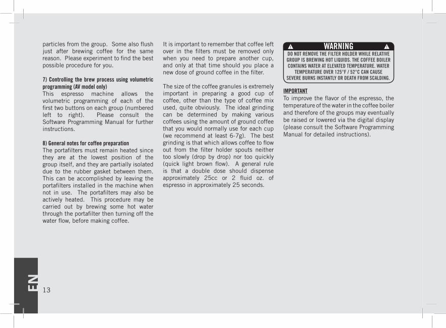
6) Brewing coffeeIt is now possible to remove one of the portafilters to make an espresso beverage. Place some ground coffee in the filter itself: 1 dose (approximately 6-7 g) for the small filter, 2 doses (2 approximately 12-15 g) for the larger filter. Press down on the ground coffee with the supplied tamper and install the filter holder up again to the bottom of the group and then press a button (AV model) to begin the brewing process, or move the paddle lever (MP model see picture below).
Note: Some baristas believe it is important to press the brewing button prior to installing the portafilter to allow the water to flush any remaining coffee oils and
Filter Basket
Porta Filter
O-ring Gasket
Double Spout
off pre-brewing brewing
EN 13
particles from the group. Some also flush just after brewing coffee for the same reason. Please experiment to find the best possible procedure for you.
7) Controlling the brew process using volumetric programming (AV model only)This espresso machine allows the volumetric programming of each of the first two buttons on each group (numbered left to right). Please consult the Software Programming Manual for further instructions.
8) General notes for coffee preparationThe portafilters must remain heated since they are at the lowest position of the group itself, and they are partially isolated due to the rubber gasket between them. This can be accomplished by leaving the portafilters installed in the machine when not in use. The portafilters may also be actively heated. This procedure may be carried out by brewing some hot water through the portafilter then turning off the water flow, before making coffee.
It is important to remember that coffee left over in the filters must be removed only when you need to prepare another cup, and only at that time should you place a new dose of ground coffee in the filter.
The size of the coffee granules is extremely important in preparing a good cup of coffee, other than the type of coffee mix used, quite obviously. The ideal grinding can be determined by making various coffees using the amount of ground coffee that you would normally use for each cup (we recommend at least 6-7g). The best grinding is that which allows coffee to flow out from the filter holder spouts neither too slowly (drop by drop) nor too quickly (quick light brown flow). A general rule is that a double dose should dispense approximately 25cc or 2 fluid oz. of espresso in approximately 25 seconds.
IMPORTANTTo improve the flavor of the espresso, the temperature of the water in the coffee boiler and therefore of the groups may eventually be raised or lowered via the digital display (please consult the Software Programming Manual for detailed instructions).
WARNINGDO NOT REMOVE THE FILTER HOLDER WHILE RELATIVE GROUP IS BREWING HOT LIQUIDS. THE COFFEE BOILER CONTAINS WATER AT ELEVATED TEMPERATURE. WATER
TEMPERATURE OVER 125°F / 52°C CAN CAUSE SEVERE BURNS INSTANTLY OR DEATH FROM SCALDING.
EN14
5. Dispensing Steam and Hot Water 1) Steaming milk or other liquidsIn order to allow for any condensed water in the wand to be released ALWAYS allow some steam to be discharged by turning on the valve before inserting the steam wand into the pitcher of liquid to be heated.Dip one of the 2 steam wands (part 8, fig. 1) which are connected to the steam valve, into the liquid to be heated, turn the steam knob (part 9, fig. 1) gradually until steam comes out at the end of the wand.The steam will transfer heat to the liquid raising its temperature up to boiling point.Be careful not to allow liquid to overflow in order to avoid severe burns.In order to prepare milk for making cappuccino with the right amount of foam, go through the following steps:• Place the container half-full of milk under the steam wand, open the steam valve and heat the milk to desired temperature.
• Lower the container so as to bring the wand end to a point just below the surface of the milk; at this point, move the container up and down just enough to dip the nozzle end in and out of the milk until you get the right amount of foam. You can then pour this milk into a cup containing warm espresso and you will end up with a fresh cup of cappuccino.
In order to prevent the heated liquid from being sucked back into the steam boiler it is recommended that you purge the steam valve and steam wand by opening the valve for a few seconds to allow steam to escape to the atmosphere from the end of the steam wand. Failure to do so can cause the heated liquid to transfer from the heated liquid container to the steam boiler (via vacuum created from cooling parts). This condition is undesireable and can cause contamination in the steam boiler.
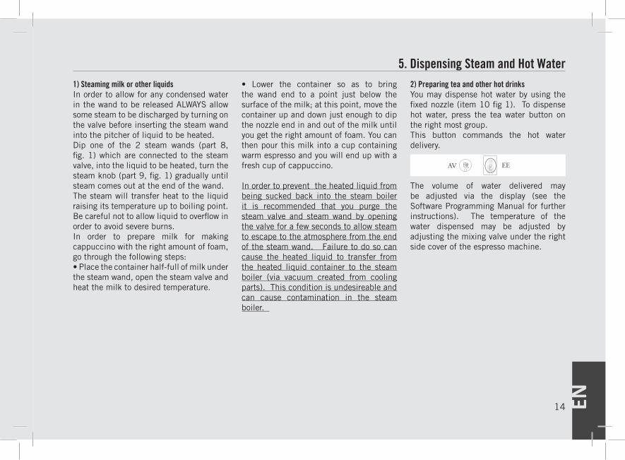
2) Preparing tea and other hot drinksYou may dispense hot water by using the fixed nozzle (item 10 fig 1). To dispense hot water, press the tea water button on the right most group.This button commands the hot water delivery.
The volume of water delivered may be adjusted via the display (see the Software Programming Manual for further instructions). The temperature of the water dispensed may be adjusted by adjusting the mixing valve under the right side cover of the espresso machine.
EN 15
1) Cleaning groups and drain wells- Put a half teaspoon of detergent powder for coffee machines into the blind filter, supplied with the machine, and tighten it onto the group you want to clean by using a normal filter holder.- Activate the automating rinsing (backflushing) routine (see the Software Programming Manual for more detailed instructions). - Rinse the group using a normal filter, by running hot water through it several times
2) Cleaning filters and filter holders- Put 2 or 3 teaspoons of detergent powder for coffee machines in about 1/2 a litre of water inside a heat-resistant container and heat.- Dip filters and filter holders (but not the handles) in the heated solution and
leave them fully submerged for about 30 minutes. - Rinse thoroughly with clean water and run hot water through one group several times with the filters in place. - Make one cup of coffee and discard in order to remove any unpleasant flavor.
3) Cleaning the drain collectorRemove the drain tray grill at least twice a week and clean, pull out the water drain collector and clean it thoroughly. Inspect and clean the drain well also, and remove any leftover grounds.
4) Cleaning the bodyWipe the stainless steel surfaces with a soft, non abrasive cloth in the direction of the glazing marks, if any. Do not use any alcohol or solvents whatsoever on painted
6. Maintenance and Periodic Cleaning Operationsor imprinted parts in order not to damage them.
5) Cleaning the hot water and steam nozzlesSteam nozzles must be cleaned immediately after use with a damp cloth and by producing a short burst of steam so as to prevent the formation of deposits inside the nozzles themselves, which may alter the flavor of other drinks to be heated. Hot water nozzles must be cleaned periodically with a damp cloth.
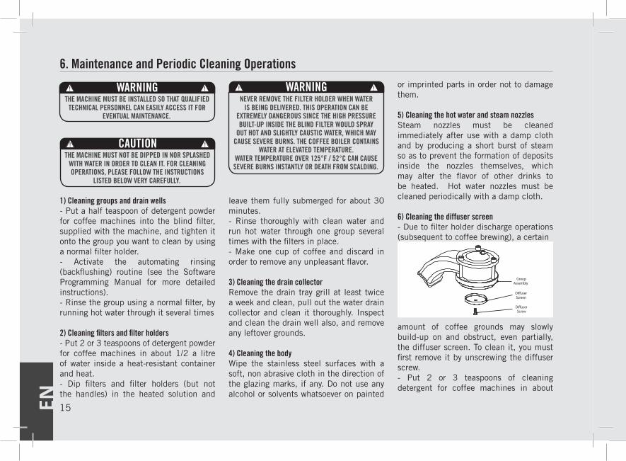
6) Cleaning the diffuser screen- Due to filter holder discharge operations (subsequent to coffee brewing), a certain
Di�user Screen
Group Assembly
Di�user Screw
amount of coffee grounds may slowly build-up on and obstruct, even partially, the diffuser screen. To clean it, you must first remove it by unscrewing the diffuser screw. - Put 2 or 3 teaspoons of cleaning detergent for coffee machines in about
CAUTIONTHE MACHINE MUST NOT BE DIPPED IN NOR SPLASHED
WITH WATER IN ORDER TO CLEAN IT. FOR CLEANING OPERATIONS, PLEASE FOLLOW THE INSTRUCTIONS
LISTED BELOW VERY CAREFULLY.
WARNINGNEVER REMOVE THE FILTER HOLDER WHEN WATER
IS BEING DELIVERED. THIS OPERATION CAN BE EXTREMELY DANGEROUS SINCE THE HIGH PRESSURE BUILT-UP INSIDE THE BLIND FILTER WOULD SPRAY
OUT HOT AND SLIGHTLY CAUSTIC WATER, WHICH MAY CAUSE SEVERE BURNS. THE COFFEE BOILER CONTAINS
WATER AT ELEVATED TEMPERATURE. WATER TEMPERATURE OVER 125°F / 52°C CAN CAUSE SEVERE BURNS INSTANTLY OR DEATH FROM SCALDING.
WARNINGTHE MACHINE MUST BE INSTALLED SO THAT QUALIFIED
TECHNICAL PERSONNEL CAN EASILY ACCESS IT FOR EVENTUAL MAINTENANCE.
EN16
1/2 a litre of very hot water inside a heat-resistant container. - Place the diffuser screen(s) and diffuser screw(s) in the solution and leave them fully submerged for about 30 minutes.
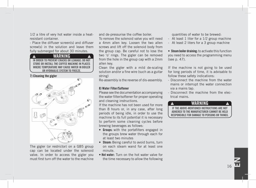
7) Cleaning the gigler
The gigler (or restrictor) on a GB5 group cap can be located under the solenoid valve. In order to access the gigler you must first turn off the water to the machine
and de-pressurise the coffee boiler.To remove the solenoid valve you will need a 4mm allen key. Loosen the two allen screws and lift off the solenoid body from the group cap. Be careful not to lose the two ‘o’ rings. The gigler can be removed from the hole in the group cap with a 2mm allen key.Clean the gigler with a mild de-scaling solution and/or a fine wire (such as a guitar string)Re-assembly is the reverse of dis-assembly.
8) Water Filter/SoftenerPlease see the documentation accompanying the water filter/softener for proper operating and cleaning instructions.If the machine has not been used for more than 8 hours or, in any case, after long periods of being idle, in order to use the machine to its full potential it is necessary to perform some cleaning cycles before brewing beverages as follows:• Groups: with the portafilters engaged in
the groups brew water through each for at least two minutes
• Steam: Being careful to avoid burns, turn on each steam wand for at least one minute.
• Hot water: Turn on the hot water valve for the time necessary to allow the following
quantities of water to be brewed: - At least 1 liter for a 1/2 group machine - At least 2 liters for a 3 group machine
• Steam boiler draining: to activate this function you need to access the programming menu (see p. 47).
If the machine is not going to be used for long periods of time, it is advisable to follow these safety indications:- Disconnect the machine from the water
mains or interrupt the water connection via a mains tap.
- Disconnect the machine from the elec-trical mains.
WARNINGIN ORDER TO PREVENT CRACKS OR LEAKAGE: DO NOT STORE OR INSTALL THE COFFEE MACHINE IN PLACES WHERE TEMPERATURE MAY CAUSE WATER IN BOILER
OR HYDRAULIC SYSTEM TO FREEZE.
WARNINGIF THE ABOVE-MENTIONED INSTRUCTIONS ARE NOT ADHERED TO THE MANUFACTURER CANNOT BE HELD
RESPONSIBLE FOR DAMAGE TO PERSONS OR THINGS.
EN 17
7. De-Commissioning and Demolition1) De-commissioning and demolition
Start by setting the main switch to the “0” or OFF position.
Disconnecting from the power outletDisconnect the espresso machine from the electrical network by switching off the associated circuit breaker or circuit protection device. Remove the power supply cord from the power connection. Remove the Pump Motor Power Cord from the water pump motor.
Disconnecting from the water systemShut off the water supply by closing the specific tap located upstream of the water filter/softener inlet. Disconnect the water pipe at the water filter/softener inlet.
Remove the hose connecting the espresso machine to the water pump. Remove the reinforced plastic tubing on the drain connection.
At this point, the machine may be removed from the bar, being very careful not to drop it.
The machine is made out of various materials and therefore, if you do not intend to put it back in service, it must be taken to a special disposal company which will select the materials which can be recycled and discard the others.
Current regulations make it illegal to discard such machine by leaving it on public grounds or on any private property.
Recycling notice: Warning for the protection of the environment.Used Electrical and electronic waste contains hazardous but also valuable and scarce materials which should be recovered and recycled properly. We kindly ask that you contribute to the protection of the environment and natural resources by delivering used equipment to the relevant recycling locations if such locations are available in your country.
EN18
8. Mandatory Maintenance and Check-up OperationsThese operations are in addition to the Maintenance and Periodic Cleaning Operations as specified in Chapter 7.
The following maintenance and check-up operations should be carried out by a qualified technician.The time required for the periodic maintenance is determinated by the quantity of daily work and/or coffee consumption.
N.B. These periodic maintenance operations are not covered by warranty.
▪ Replace portafilter baskets▪ Inspect group valve plungers▪ Inspect vacuum breaker▪ Inspect expansion valve▪ Inspect electrical wiring condition
▪ Inspect boilers safety switches▪ Replace over-pressure valve (safety valve)▪ Accurate control of the tightness at 2,4Nm of each cable on the terminal block.
EVERY THREE/FOUR MONTHS
EVERY SIX/EIGHT MONTHS (in addition to the above)
EVERY YEAR (in addition to the above)
EVERY 3 YEARS (in addition to the above)
▪ Replace group gaskets▪ Replace diffuser screens▪ Clean auto-fill probe▪ Check vacuum breaker for proper operation▪ Inspect water inlet valve▪ Inspect drain system for leaks or clogs▪ Check flow rate for each group
▪ Check brew temperature▪ Check that brew pressure is at 9bar▪ Check all switches for proper operation▪ Check/note water hardness (Water quality must be within the range of parameters specified in the chapter on Installation,
otherwise warranty is voided)▪ Check filter basket condition
If AV Model:▪ Check shot volumes▪ Test flowmeter’s ohm value (ohm value is acceptable if greater than 1.8 K ohm, and less than 2.2 K ohm
If MP Model: ▪ Rebuild MP valve
▪ Check the condition of the inside of boilers and if necessary rinse out with a proper cleaning product allowed for food and beverage appliances.
▪ Rebuild steam assemblies
EN 19
Digital Display page 20
Programming Keypad page 21
Programming Mode page 22
Initial Installation page 23
Turning the Espresso Machine On page 24
Turning the Espresso Machine Off page 25
“Barista” Programming
Water Volume Programming page 26
Nominal Coffee Boiler
Temperature page 27
Cup Heating page 28
Doses Reading page 29
Clock Adjust page 30
Auto On/Off page 31
“Technical” Programming
Language page 32
Temperature Adjustment page 33
Total Doses page 34
Cronos Function page 35
User Name page 36
Times Cup Heating page 37
Pre-Brewing page 39
Filter Alarm page 40
Steam Boiler Automatic Fill page 41
Tea Water page 43
Steam Boiler Pressure Regulation page 44
Steam Boiler Temperature
Correction page 45
Open Valve page 46
Drain Steam Boiler page 47
Safety Valve page 48
Technician Password Assignment page 49
Water Volume Programming page 50
Nominal Coffee Boiler
Temperature page 52
Cup Heating page 53
Doses Reading page 54
Clock Adjust page 55
Auto On/Off page 56
Pre-Programmed Rinsing
(Back Flushing) Routine page 58
Troubleshooting page 59
EE - Table of Contents page 60
AV - Table of Contents 9. Software Programming Guide
EN20
AV Programming IntroductionDescription
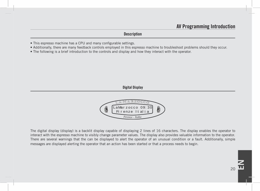
• This espresso machine has a CPU and many configurable settings.• Additionally, there are many feedback controls employed in this espresso machine to troubleshoot problems should they occur.• The following is a brief introduction to the controls and display and how they interact with the operator.
The digital display (display) is a backlit display capable of displaying 2 lines of 16 characters. The display enables the operator to interact with the espresso machine to visibly change parameter values. The display also provides valuable information to the operator. There are several warnings that the can be displayed to alert the operator of an unusual condition or a fault. Additionally, simple messages are displayed alerting the operator that an action has been started or that a process needs to begin.
Digital Display
LaMarzocco 09:30Firenze Italia
EN 21
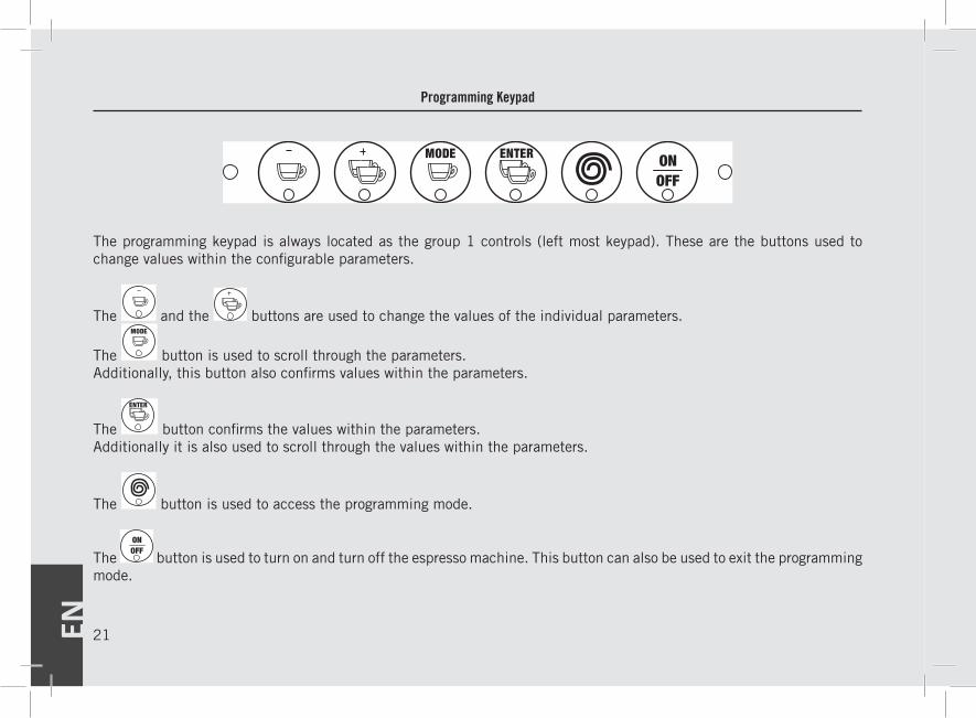
The programming keypad is always located as the group 1 controls (left most keypad). These are the buttons used to change values within the configurable parameters.
The and the buttons are used to change the values of the individual parameters.
The button is used to scroll through the parameters. Additionally, this button also confirms values within the parameters.
The button confirms the values within the parameters. Additionally it is also used to scroll through the values within the parameters.
The button is used to access the programming mode.
The button is used to turn on and turn off the espresso machine. This button can also be used to exit the programming mode.
Programming Keypad
EN22
Accessing Programming Mode
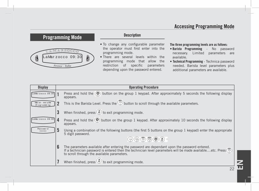
Display Operating Procedure
1
This is the Barista Level. Press the button to scroll through the available parameters.2
When finished, press to exit programming mode.3Press and hold the button on the group 1 keypad. After approximately 10 seconds the following display appears.
4
Using a combination of the following buttons (the first 5 buttons on the group 1 keypad) enter the appropriate 5 digit password.
5
The parameters available after entering the password are dependant upon the password entered.If a technician password is entered then the technician level parameters will be made available....etc. Press to scroll through the available parameters.
6
When finished, press to exit programming mode.7
LaMarzocco 09:30
Water VolumeProgramming
LaMarzocco 09:30
Password?????
LaMarzocco 09:30
Description
• To change any configurable parameter the operator must first enter into the programming mode.
• There are several levels within the programming mode that allow the restriction of specific parameters depending upon the password entered.
The three programming levels are as follows:• Barista Programming - No password
necessary. Limited parameters are available.
• Technical Programming - Technica password needed. Barista level parameters plus additional parameters are available.
Programming Mode
Press and hold the button on the group 1 keypad. After approximately 5 seconds the following display appears.
EN 23
DescriptionProgramming Mode
1
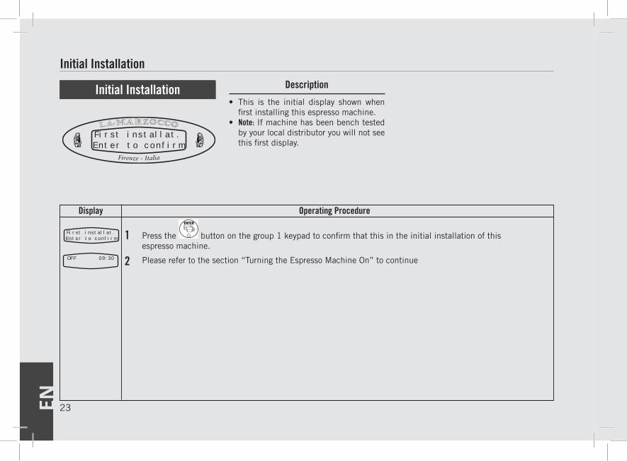
• This is the initial display shown when first installing this espresso machine.
• Note: If machine has been bench tested by your local distributor you will not see this first display.
Initial Installation
Initial Installation
2
Display Operating Procedure
First installat.Enter to confirm
Please refer to the section “Turning the Espresso Machine On” to continue
First installat.Enter to confirm
OFF 09:30
Press the button on the group 1 keypad to confirm that this in the initial installation of thisespresso machine.
EN24
Display Operating Procedure
Description
Start Up Procedures
1LaMarzocco 09:30
3
4
5
1
2
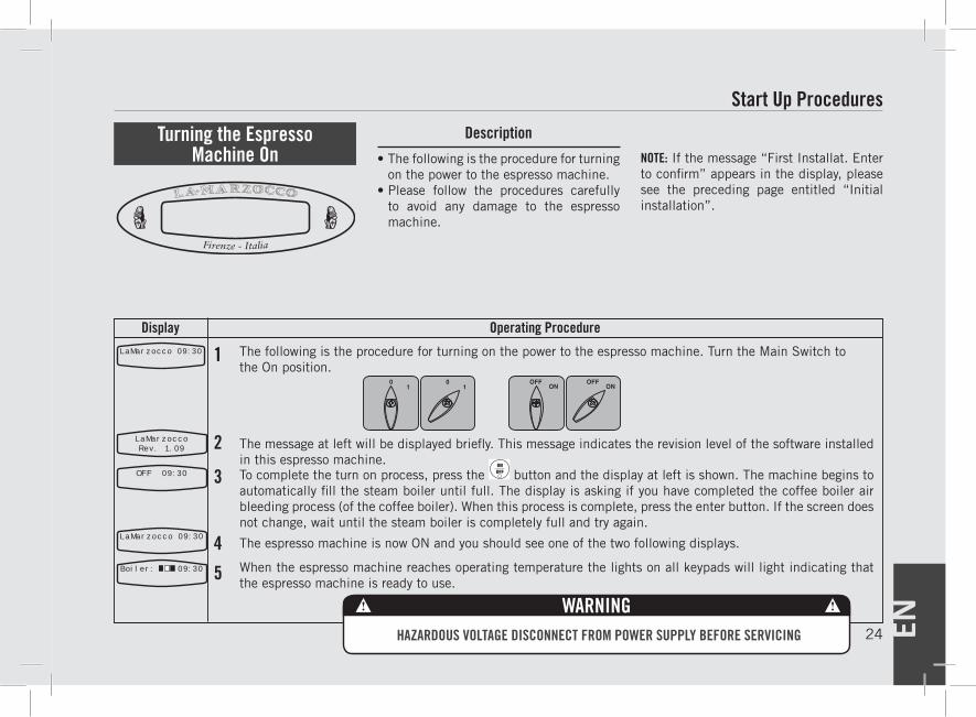
• The following is the procedure for turning on the power to the espresso machine.
• Please follow the procedures carefully to avoid any damage to the espresso machine.
NOTE: If the message “First Installat. Enter to confirm” appears in the display, please see the preceding page entitled “Initial installation”.
Turning the Espresso Machine On
The message at left will be displayed briefly. This message indicates the revision level of the software installed in this espresso machine.To complete the turn on process, press the button and the display at left is shown. The machine begins to automatically fill the steam boiler until full. The display is asking if you have completed the coffee boiler air bleeding process (of the coffee boiler). When this process is complete, press the enter button. If the screen does not change, wait until the steam boiler is completely full and try again.
The espresso machine is now ON and you should see one of the two following displays.
When the espresso machine reaches operating temperature the lights on all keypads will light indicating that the espresso machine is ready to use.
LaMarzoccoRev. 1.09
OFF 09:30
LaMarzocco 09:30
Boiler: 09:30
The following is the procedure for turning on the power to the espresso machine. Turn the Main Switch to the On position.
HAZARDOUS VOLTAGE DISCONNECT FROM POWER SUPPLY BEFORE SERVICING
WARNING
EN 25
Display Operating Procedure
DescriptionProgramming Mode
1LaMarzocco 09:30
2
3
4
5
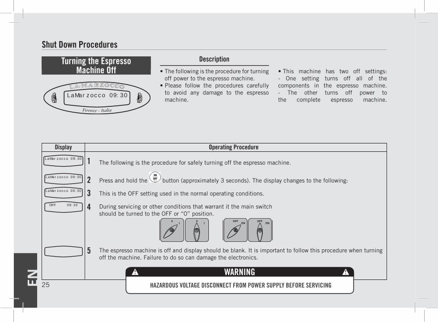
The following is the procedure for safely turning off the espresso machine.
Press and hold the button (approximately 3 seconds). The display changes to the following:
This is the OFF setting used in the normal operating conditions.
During servicing or other conditions that warrant it the main switch should be turned to the OFF or “0” position.
The espresso machine is off and display should be blank. It is important to follow this procedure when turning off the machine. Failure to do so can damage the electronics.
• The following is the procedure for turning off power to the espresso machine.
• Please follow the procedures carefully to avoid any damage to the espresso machine.
• This machine has two off settings: - One setting turns off all of the components in the espresso machine.- The other turns off power to the complete espresso machine.
Turning the Espresso Machine Off
Shut Down Procedures
LaMarzocco 09:30
LaMarzocco 09:30
OFF 09:30
LaMarzocco 09:30
HAZARDOUS VOLTAGE DISCONNECT FROM POWER SUPPLY BEFORE SERVICING
WARNING
EN26
Display Operating Procedure
Description
1LaMarzocco 09:30
2
3
45
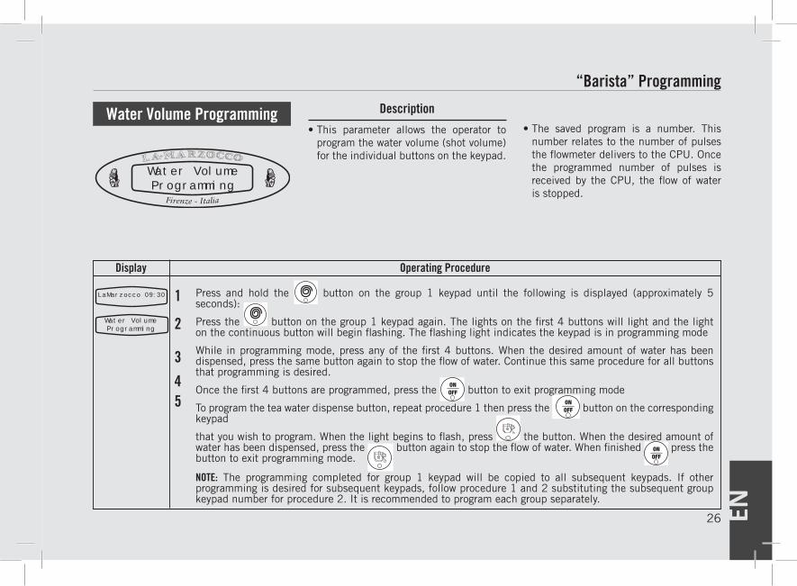
Press and hold the button on the group 1 keypad until the following is displayed (approximately 5 seconds):
Press the button on the group 1 keypad again. The lights on the first 4 buttons will light and the light on the continuous button will begin flashing. The flashing light indicates the keypad is in programming mode
While in programming mode, press any of the first 4 buttons. When the desired amount of water has been dispensed, press the same button again to stop the flow of water. Continue this same procedure for all buttons that programming is desired.
Once the first 4 buttons are programmed, press the button to exit programming mode
To program the tea water dispense button, repeat procedure 1 then press the button on the corresponding
keypad
that you wish to program. When the light begins to flash, press the button. When the desired amount of water has been dispensed, press the
button again to stop the flow of water. When finished press the
button to exit programming mode.
“Barista” Programming
• This parameter allows the operator to program the water volume (shot volume) for the individual buttons on the keypad.
• The saved program is a number. This number relates to the number of pulses the flowmeter delivers to the CPU. Once the programmed number of pulses is received by the CPU, the flow of water is stopped.
Water Volume Programming
Water VolumeProgramming
Water VolumeProgramming
NOTE: The programming completed for group 1 keypad will be copied to all subsequent keypads. If other programming is desired for subsequent keypads, follow procedure 1 and 2 substituting the subsequent group keypad number for procedure 2. It is recommended to program each group separately.
EN 27
Display Operating Procedure
DescriptionProgramming Mode
1LaMarzocco 09:30
2
3
4
5
6
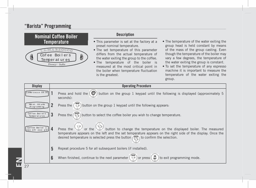
Press and hold the button on the group 1 keypad until the following is displayed (approximately 5 seconds):
Press the button on the group 1 keypad until the following appears:
Press the button to select the coffee boiler you wish to change temperature.
Press the or the button to change the temperature on the displayed boiler. The measured temperature appears on the left and the set temperature appears on the right side of the display. Once the desired temperature is selected press the button to confirm the selection.
Repeat procedure 5 for all subsequent boilers (if installed).
When finished, continue to the next parameter or press to exit programming mode.
• This parameter is set at the factory at a preset nominal temperature.
• The set temperature of this parameter differs from the actual temperature of the water exiting the group to the coffee.
• The temperature of the boiler is measured at the most critical point in the boiler when temperature fluctuation is the greatest.
• The temperature of the water exiting the group head is held constant by means of the mass of the group casting. Even though the temperature of the boiler may vary a few degrees, the temperature of the water exiting the group is constant.
• To set the temperature of any espresso machine it is important to measure the temperature of the water exiting the group.
Nominal Coffee Boiler Temperature
“Barista” Programming
Water VolumeProgramming
Coffee BoilersTemperatures
Coffee Boiler 1202.5 F 202.6 F
Cofee BoilersTemperatures

EN28
Display Operating Procedure
Description
1LaMarzocco 09:30
2
3
4
Press and hold the button on the group 1 keypad until the following is displayed (approximately 5 seconds):
Press the button on the group 1 keypad until the following appears:
Press the or the button to change to ON or OFF. Once the desired condition is displayed press the button to confirm.
When finished, continue to the next parameter or press to exit programming mode.
“Barista” Programming
• This parameter allows the user to enable or disable the cup heating routine.
• The cup heater is an option ordered from the factory, not available in the USA & Canada.
• Additional parameter settings are available in the factory level parameters under Cup Heating Times.
Cup Heating
Cup heatingOFF
Water VolumeProgramming
Cup heatingOFF
EN 29
Display Operating Procedure
DescriptionProgramming Mode
1LaMarzocco 09:30
2
3
4
Press and hold the button on the group 1 keypad until the following is displayed (approximately 5 seconds):
Press the button on the group 1 keypad until the following appears:
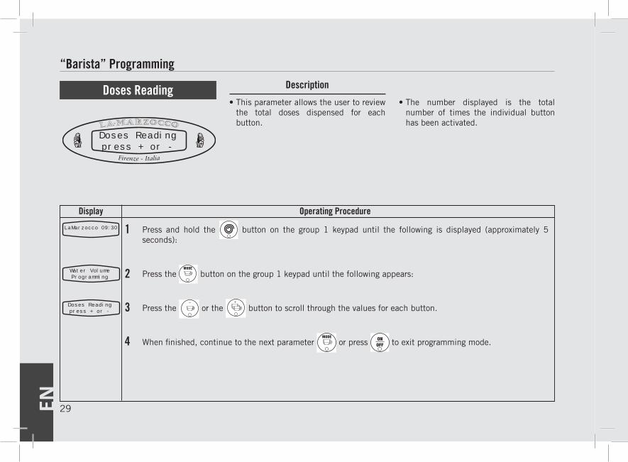
Press the or the button to scroll through the values for each button.
When finished, continue to the next parameter or press to exit programming mode.
“Barista” Programming
• This parameter allows the user to review the total doses dispensed for each button.
• The number displayed is the total number of times the individual button has been activated.
Doses Reading
Doses Readingpress + or -
Water VolumeProgramming
Doses Readingpress + or -
EN30
Display Operating Procedure
Description
1LaMarzocco 09:30
2
3
4
5
Press and hold the button on the group 1 keypad until the following is displayed (approximately 5 seconds):
Press the button on the group 1 keypad until the following appears:
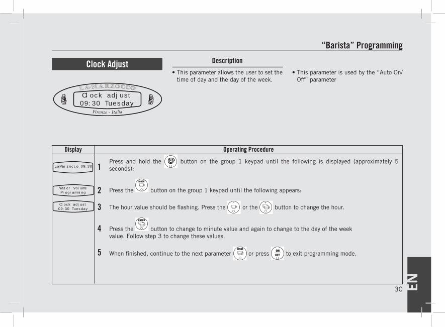
The hour value should be flashing. Press the or the button to change the hour.
Press the button to change to minute value and again to change to the day of the weekvalue. Follow step 3 to change these values.
When finished, continue to the next parameter or press to exit programming mode.
“Barista” Programming
• This parameter allows the user to set the time of day and the day of the week.
• This parameter is used by the “Auto On/Off” parameter
Clock Adjust
Clock adjust09:30 Tuesday
Water VolumeProgramming
Clock adjust09:30 Tuesday
EN 31
Display Operating Procedure
DescriptionProgramming Mode
1LaMarzocco 09:30
2
3
4
5
6
7
8
Press and hold the button on the group 1 keypad until the following is displayed (approximately 5 seconds):
Press the button on the group 1 keypad until the following appears:
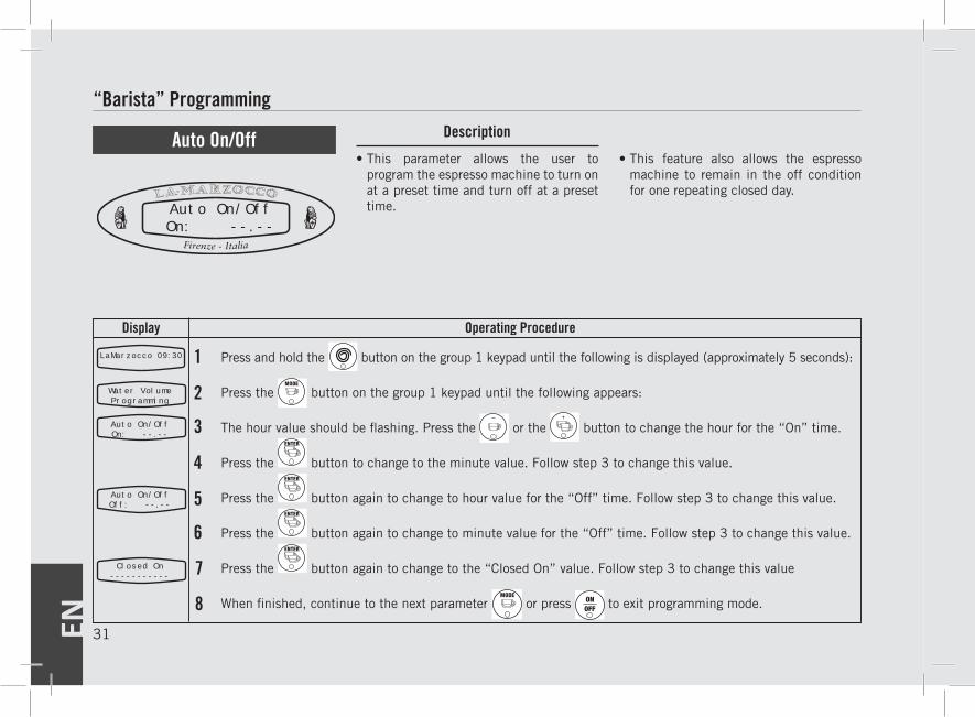
The hour value should be flashing. Press the or the button to change the hour for the “On” time.
Press the button to change to the minute value. Follow step 3 to change this value.
Press the button again to change to hour value for the “Off” time. Follow step 3 to change this value.
Press the button again to change to minute value for the “Off” time. Follow step 3 to change this value.
Press the button again to change to the “Closed On” value. Follow step 3 to change this value
When finished, continue to the next parameter or press to exit programming mode.
“Barista” Programming
• This parameter allows the user to program the espresso machine to turn on at a preset time and turn off at a preset time.
• This feature also allows the espresso machine to remain in the off condition for one repeating closed day.
Auto On/Off
Auto On/OffOn: --.--
Water VolumeProgramming
Auto On/OffOn: --.--
Auto On/OffOff: --.--
Closed On-----------
EN32
Display Operating Procedure
Description
1LaMarzocco 09:30
2
3
4
Press and hold the button on the group 1 keypad until the following is displayed (approximately 10 seconds):
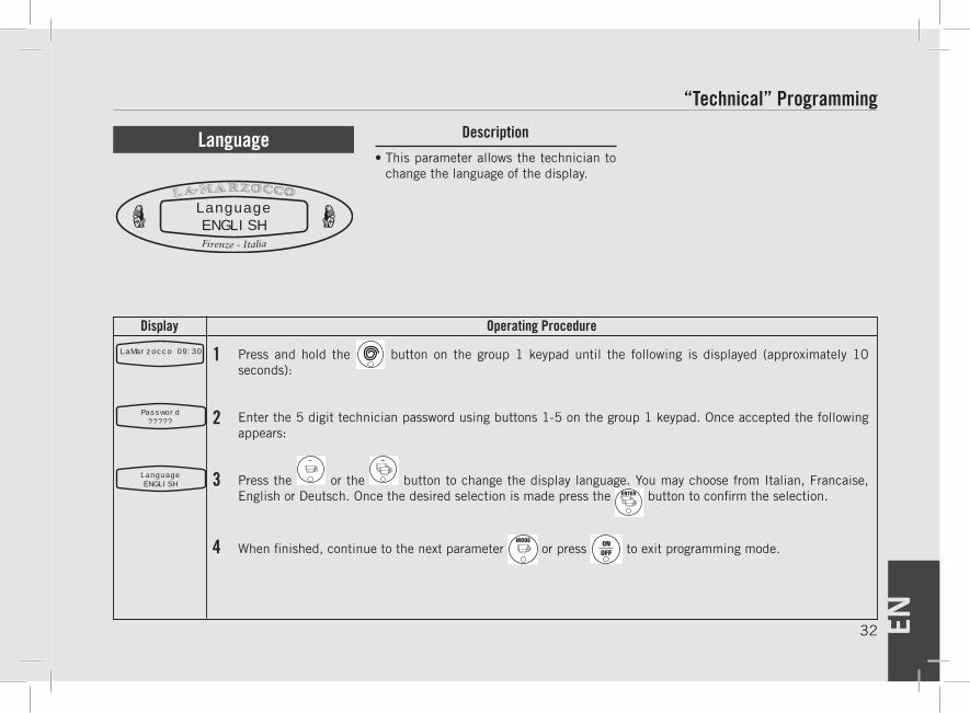
Enter the 5 digit technician password using buttons 1-5 on the group 1 keypad. Once accepted the following appears:
Press the or the button to change the display language. You may choose from Italian, Francaise, English or Deutsch. Once the desired selection is made press the button to confirm the selection.
When finished, continue to the next parameter or press to exit programming mode.
“Technical” Programming
• This parameter allows the technician to change the language of the display.
Language
LanguageENGLISH
Password?????
LanguageENGLISH
EN 33
Display Operating Procedure
DescriptionProgramming Mode
1LaMarzocco 09:30
2
3
4
5
6
7
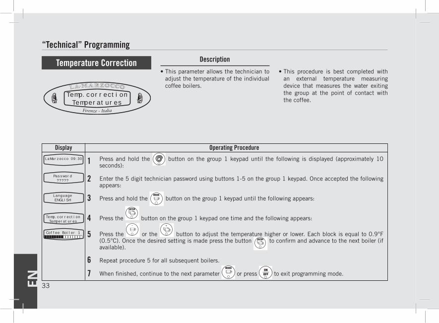
Press and hold the button on the group 1 keypad until the following is displayed (approximately 10 seconds):
Enter the 5 digit technician password using buttons 1-5 on the group 1 keypad. Once accepted the following appears:
Press and hold the button on the group 1 keypad until the following appears:
Press the button on the group 1 keypad one time and the following appears:
Press the or the button to adjust the temperature higher or lower. Each block is equal to 0.9°F (0.5°C). Once the desired setting is made press the button to confirm and advance to the next boiler (if available).
Repeat procedure 5 for all subsequent boilers.
When finished, continue to the next parameter or press to exit programming mode.
“Technical” Programming
• This parameter allows the technician to adjust the temperature of the individual coffee boilers.
• This procedure is best completed with an external temperature measuring device that measures the water exiting the group at the point of contact with the coffee.
Temperature Correction
Temp.correctionTemperatures
Password?????
LanguageENGLISH
Temp.correctionTemperatures
Coffee Boiler 1

EN34
Display Operating Procedure
Description
“Technical” Programming
1LaMarzocco 09:30
2
3
4
5
Press and hold the button on the group 1 keypad until the following is displayed (approximately 10 seconds)
Enter the 5 digit technician password using buttons 1-5 on the group 1 keypad. Once accepted the following appears:
Press the button on the group 1 keypad until the following appears:
The number displayed is the total number of doses that this machine has produced
When finished, continue to the next parameter or press to exit programming mode.
• This parameter keeps a count of each dose that is produced with this espresso machine.
• This number can be an important reference when troubleshooting the espresso machine.
• This number cannot be adjusted nor reset.
Total Doses
Password?????
LanguageENGLISH
Total Doses15
Total doses15
EN 35
Display Operating Procedure
DescriptionProgramming Mode
“Technical” Programming
1LaMarzocco 09:30
2
34
5
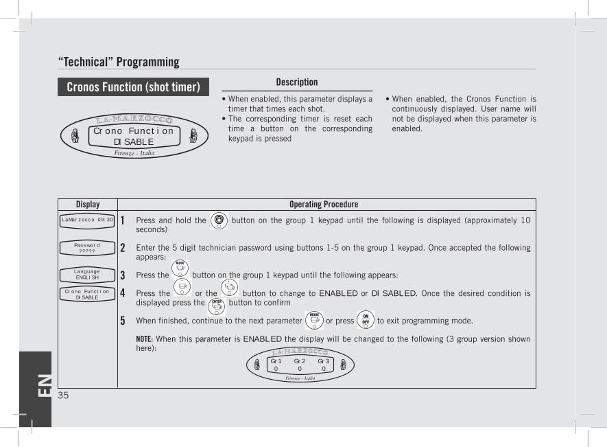
Press and hold the button on the group 1 keypad until the following is displayed (approximately 10 seconds)
Enter the 5 digit technician password using buttons 1-5 on the group 1 keypad. Once accepted the following appears:
Press the button on the group 1 keypad until the following appears:
Press the or the button to change to ENABLED or DISABLED. Once the desired condition is displayed press the button to confirm
When finished, continue to the next parameter or press to exit programming mode.
NOTE: When this parameter is ENABLED the display will be changed to the following (3 group version shown here):
• When enabled, this parameter displays a timer that times each shot.
• The corresponding timer is reset each time a button on the corresponding keypad is pressed
• When enabled, the Cronos Function is continuously displayed. User name will not be displayed when this parameter is enabled.
Cronos Function (shot timer)
Crono FunctionDISABLE
Password?????
LanguageENGLISH
Crono FunctionDISABLE
Gr1 Gr2 Gr30 0 0
EN36
Display Operating Procedure
Description
“Technical” Programming
1LaMarzocco 09:30
2
3
4
5
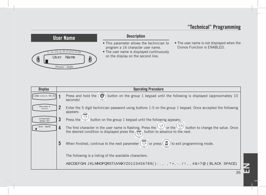
Press and hold the button on the group 1 keypad until the following is displayed (approximately 10 seconds)
Enter the 5 digit technician password using buttons 1-5 on the group 1 keypad. Once accepted the following appears:
Press the button on the group 1 keypad until the following appears:
The first character in the user name is flashing. Press the or the button to change the value. Once the desired condition is displayed press the button to advance to the next.
When finished, continue to the next parameter or press to exit programming mode.
The following is a listing of the available characters:
ABCDEFGHIJKLMNOPQRSTUVWXYZ0123456789():., ,*+,-./!,,#&=?@ (BLACK SPACE)
• This parameter allows the technician to program a 16 character user name.
• The user name is displayed continuously on the display on the second line.
• The user name is not displayed when the Cronos Function is ENABLED.
User Name
Password?????
LanguageENGLISH
User Name .
User Name .

EN 37
Display Operating Procedure
DescriptionProgramming Mode
1LaMarzocco 09:30
2
3
4
5
Press and hold the button on the group 1 keypad until the following is displayed (approximately 10 seconds)
Enter the 5 digit technician password using buttons 1-5 on the group 1 keypad. Once accepted the following appears:
Press the button on the group 1 keypad until the following appears:
Press the button to enter the menu.
Move between the parameters with the buttons or to set the desired time. Press the button to confirm the value.
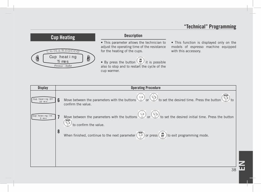
• This parameter allows the technician to adjust the operating time of the resistance for the heating of the cups.
• Press the button it is possible to stop and to restart the cycle of the cup warmer.
• This function is displayed only on the models of espresso machine equipped with this accessory.
Cup Heating
Cup heatingTimes
Password?????
LanguageENGLISH
Cup heating On3 min
Cup heatingTimes
“Technical” Programming
EN38
Display Operating Procedure
Description
Move between the parameters with the buttons or to set the desired time. Press the button to confirm the value.
Move between the parameters with the buttons or to set the desired initial time. Press the button
to confirm the value.
When finished, continue to the next parameter or press to exit programming mode.
• This parameter allows the technician to adjust the operating time of the resistance for the heating of the cups.
• By press the button it is possible also to stop and to restart the cycle of the cup warmer.
• This function is displayed only on the models of espresso machine equipped with this accessory.
Cup Heating
Cup heatingTimes
Cup heating Off10 min 6
Cup heating Ini.3 min 7
8
“Technical” Programming
EN 39
Display Operating Procedure
DescriptionProgramming Mode
“Technical” Programming
1LaMarzocco 09:30
2
3
4
5
6
7
Press and hold the button on the group 1 keypad until the following is displayed (approximately 10 seconds)
Enter the 5 digit technician password using buttons 1-5 on the group 1 keypad. Once accepted the following appears:
Press the button on the group 1 keypad until the following appears:
Press the or the button to change to ENABLED or DISABLED. Once the desired condition is displayed press the button to confirm.
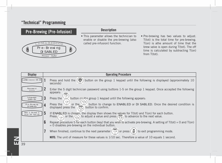
If ENABLED is chosen, the display then shows the values for T(tot) and T(on) for each button.Press or the to adjust a value and press to advance to the next value.
Repeat procedure 5 for each button (key) that you wish to activate pre-brewing. A setting of T(tot) = 0 and T(on) = 0 disables pre-brewing on the individual button.
When finished, continue to the next parameter or press to exit programming mode.
NOTE: The unit of measure for these values is 1/10 sec. Therefore a value of 10 equals 1 second.
• This parameter allows the technician to enable or disable the pre-brewing (also called pre-infusion) function.
• Pre-brewing has two values to adjust. T(tot) is the total time for pre-brewing. T(on) is athe amount of time that the brew valve is open during T(tot). The off time is calculated by subtracting T(on) from T(tot).
Pre-Brewing (Pre-Infusion)
Pre-BrewingDISABLED
Password?????
LanguageENGLISH
Pre-BrewingDISABLED
Key 1 Group 1Ttot:20 Ton:10
EN40
Display Operating Procedure
Description
“Technical” Programming
1LaMarzocco 09:30
2
3
45
6
7
Press and hold the button on the group 1 keypad until the following is displayed (approximately 10 seconds)
Enter the 5 digit technician password using buttons 1-5 on the group 1 keypad. Once accepted the following appears:
Press the button on the group 1 keypad until the following appears:
Press the button on the group 1 keypad until the following appears:
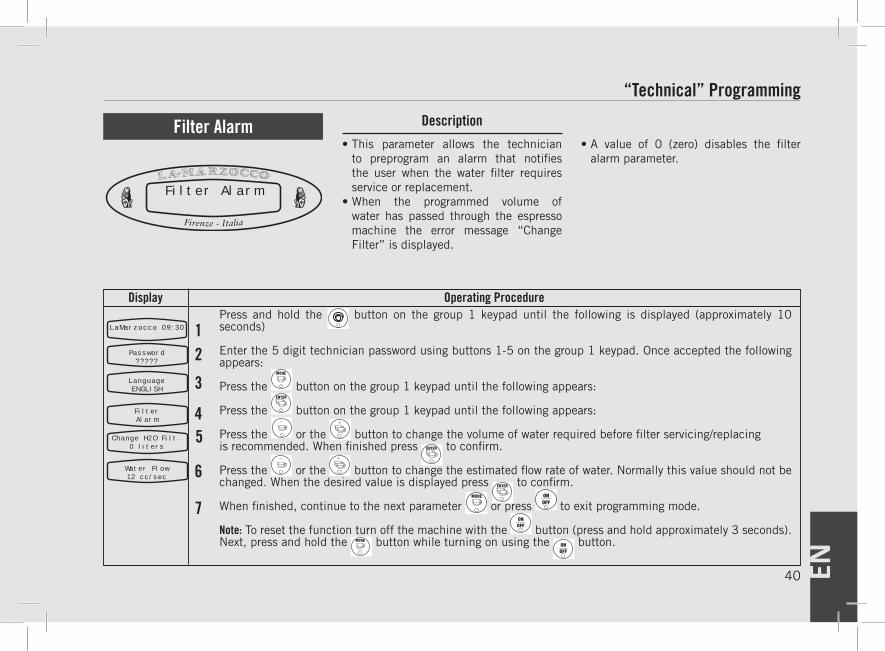
Press the or the button to change the volume of water required before filter servicing/replacing is recommended. When finished press to confirm.
Press the or the button to change the estimated flow rate of water. Normally this value should not be changed. When the desired value is displayed press to confirm.
When finished, continue to the next parameter or press to exit programming mode.
Note: To reset the function turn off the machine with the button (press and hold approximately 3 seconds). Next, press and hold the button while turning on using the button.
• This parameter allows the technician to preprogram an alarm that notifies the user when the water filter requires service or replacement.
• When the programmed volume of water has passed through the espresso machine the error message “Change Filter” is displayed.
• A value of 0 (zero) disables the filter alarm parameter.
Filter Alarm
Filter Alarm
Password?????
LanguageENGLISH
FilterAlarm
Change H2O Filt.0 liters
Water Flow12 cc/sec
EN 41
Display Operating Procedure
DescriptionProgramming Mode
“Technical” Programming
1LaMarzocco 09:30
2
3
4
5
Press and hold the button on the group 1 keypad until the following is displayed (approximately 10 seconds)
Enter the 5 digit technician password using buttons 1-5 on the group 1 keypad. Once accepted the following appears:
Press the button on the group 1 keypad until the following appears:
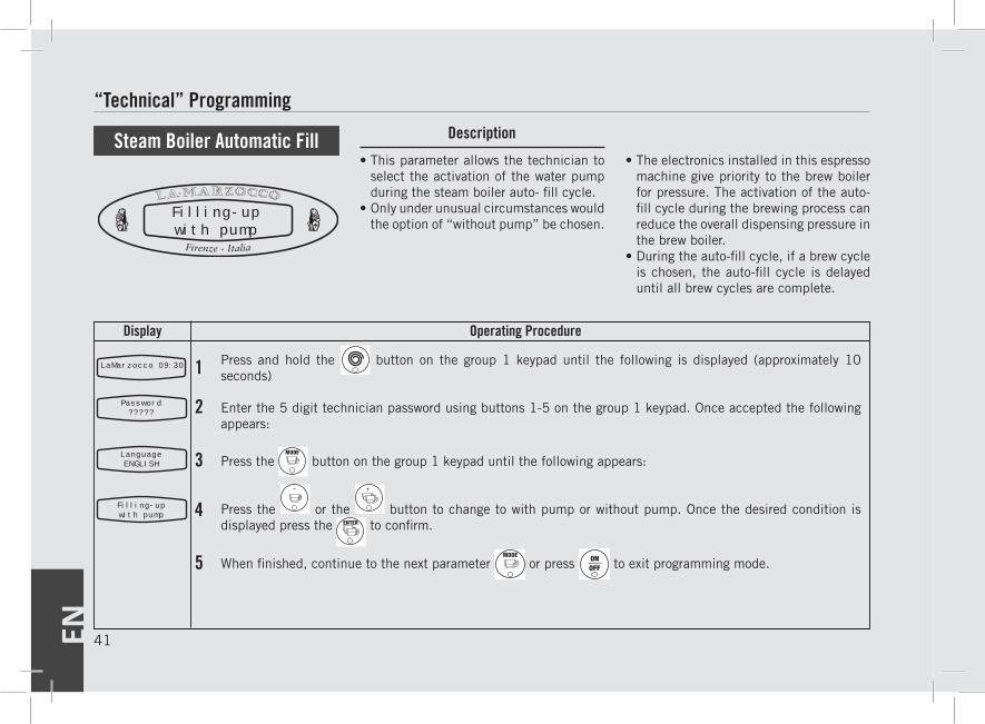
Press the or the button to change to with pump or without pump. Once the desired condition is displayed press the to confirm.
When finished, continue to the next parameter or press to exit programming mode.
• This parameter allows the technician to select the activation of the water pump during the steam boiler auto- fill cycle.
• Only under unusual circumstances would the option of “without pump” be chosen.
• The electronics installed in this espresso machine give priority to the brew boiler for pressure. The activation of the auto-fill cycle during the brewing process can reduce the overall dispensing pressure in the brew boiler.
• During the auto-fill cycle, if a brew cycle is chosen, the auto-fill cycle is delayed until all brew cycles are complete.
Steam Boiler Automatic Fill
Filling-upwith pump
Password?????
LanguageENGLISH
Filling-upwith pump
EN42
Display Operating Procedure
Description
“Technical” Programming
1LaMarzocco 09:30
2
3
4
5
Press and hold the button on the group 1 keypad until the following is displayed (approximately 10 seconds)
Enter the 5 digit technician password using buttons 1-5 on the group 1 keypad. Once accepted the following appears:
Press the button on the group 1 keypad until the following appears:
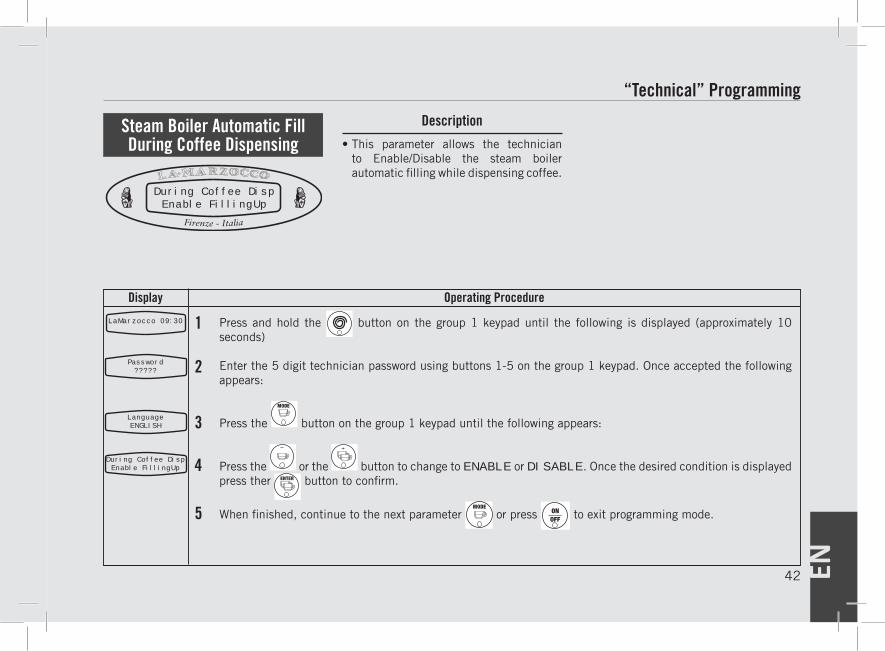
Press the or the button to change to ENABLE or DISABLE. Once the desired condition is displayed press ther button to confirm.
When finished, continue to the next parameter or press to exit programming mode.
• This parameter allows the technician to Enable/Disable the steam boiler automatic filling while dispensing coffee.
Password?????
LanguageENGLISH
During Coffee DispEnable FillingUp
During Coffee DispEnable FillingUp
Steam Boiler Automatic Fill During Coffee Dispensing

EN 43
Display Operating Procedure
DescriptionProgramming Mode
“Technical” Programming
1LaMarzocco 09:30
2
3
4
5
Press and hold the button on the group 1 keypad until the following is displayed (approximately 10 seconds)
Enter the 5 digit technician password using buttons 1-5 on the group 1 keypad. Once accepted the following appears:
Press the button on the group 1 keypad until the following appears:
Press the or the button to change to with pump or without pump. Once the desired condition is displayed press ther button to confirm.
When finished, continue to the next parameter or press to exit programming mode.
• This parameter allows the technician to select the activation of the water pump during hot water dispensing.
• When hot water is drawn from only the steam boiler this parameter should be set to “without pump”.
• If the optional adjustable temperature hot water dispense valve is installed, this parameter is set to “with pump”.
Tea Water
Password?????
LanguageENGLISH
Tea waterwithout pump
Tea waterwithout pump
EN44
Display Operating Procedure
Description
“Technical” Programming
1LaMarzocco 09:30
2
3
4
5
Press and hold the button on the group 1 keypad until the following is displayed (approximately 10 seconds)
Enter the 5 digit technician password using buttons 1-5 on the group 1 keypad. Once accepted the following appears:
Press the button on the group 1 keypad until the following appears:
Press the or the button to change the value to Pressure-switch or Temp. Probe then press
to confirm selection. Normally this value should not be changed
When finished, continue to the next parameter or press to exit programming mode.
NOTE: When this parameter is set to “Temp. Probe” an additional parameter named “Steam Temp. Cor. is activated. When changing from Temp Probe to Pressure Switch it is required to cycle power off and on through the main switch to reset the steam boiler over temperature alarm.
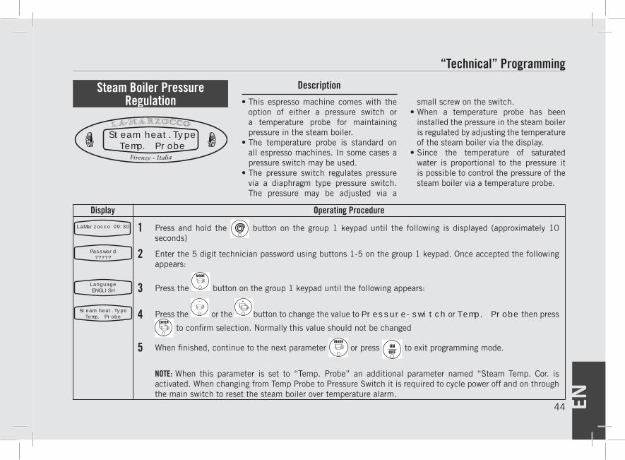
• This espresso machine comes with the option of either a pressure switch or a temperature probe for maintaining pressure in the steam boiler.
• The temperature probe is standard on all espresso machines. In some cases a pressure switch may be used.
• The pressure switch regulates pressure via a diaphragm type pressure switch. The pressure may be adjusted via a
small screw on the switch.• When a temperature probe has been
installed the pressure in the steam boiler is regulated by adjusting the temperature of the steam boiler via the display.
• Since the temperature of saturated water is proportional to the pressure it is possible to control the pressure of the steam boiler via a temperature probe.
Steam Boiler Pressure Regulation
Steam heat.TypeTemp. Probe
Password?????
LanguageENGLISH
Steam heat.TypeTemp. Probe
EN 45
Display Operating Procedure
DescriptionProgramming Mode
“Technical” Programming
1LaMarzocco 09:30
2
3
4
5
Press and hold the button on the group 1 keypad until the following is displayed (approximately 10 seconds)
Enter the 5 digit technician password using buttons 1-5 on the group 1 keypad. Once accepted the following appears:
Press the button on the group 1 keypad until the following appears:
Press the or the button to adjust the temperature higher or lower. Each block is equal to 0.9°F (0.5°C). Once the desired setting is made press the button to confirm the setting.
When finished, continue to the next parameter or press to exit programming mode.
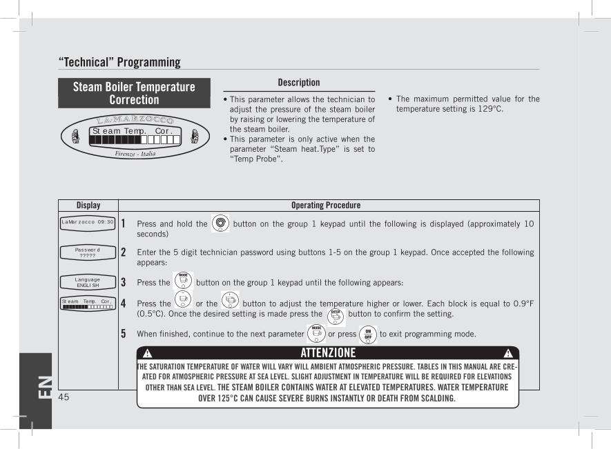
• This parameter allows the technician to adjust the pressure of the steam boiler by raising or lowering the temperature of the steam boiler.
• This parameter is only active when the parameter “Steam heat.Type” is set to “Temp Probe”.
• The maximum permitted value for the temperature setting is 129°C.
Steam Boiler Temperature Correction
Password?????
LanguageENGLISH
Steam. Temp. Cor,
Steam Temp. Cor.
THE SATURATION TEMPERATURE OF WATER WILL VARY WILL AMBIENT ATMOSPHERIC PRESSURE. TABLES IN THIS MANUAL ARE CRE-ATED FOR ATMOSPHERIC PRESSURE AT SEA LEVEL. SLIGHT ADJUSTMENT IN TEMPERATURE WILL BE REQUIRED FOR ELEVATIONS OTHER THAN SEA LEVEL. THE STEAM BOILER CONTAINS WATER AT ELEVATED TEMPERATURES. WATER TEMPERATURE
OVER 125°C CAN CAUSE SEVERE BURNS INSTANTLY OR DEATH FROM SCALDING.
ATTENZIONE
EN46
Display Operating Procedure
Description
“Technical” Programming
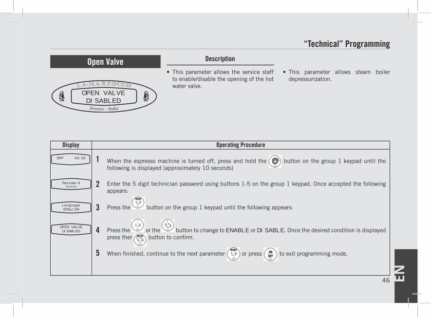
Open Valve• This parameter allows the service staff
to enable/disable the opening of the hot water valve.
OPEN VALVEDISABLED
When the espresso machine is turned off, press and hold the button on the group 1 keypad until the following is displayed (approximately 10 seconds)
Enter the 5 digit technician password using buttons 1-5 on the group 1 keypad. Once accepted the following appears:
Press the button on the group 1 keypad until the following appears:
Press the or the button to change to ENABLE or DISABLE. Once the desired condition is displayed press ther button to confirm.
When finished, continue to the next parameter or press to exit programming mode.
1
2
4
3
5
• This parameter allows steam boiler depressurization.
OFF 09:30
Password?????
LanguageENGLISH
OPEN VALVEDISABLED
EN 47
Display Operating Procedure
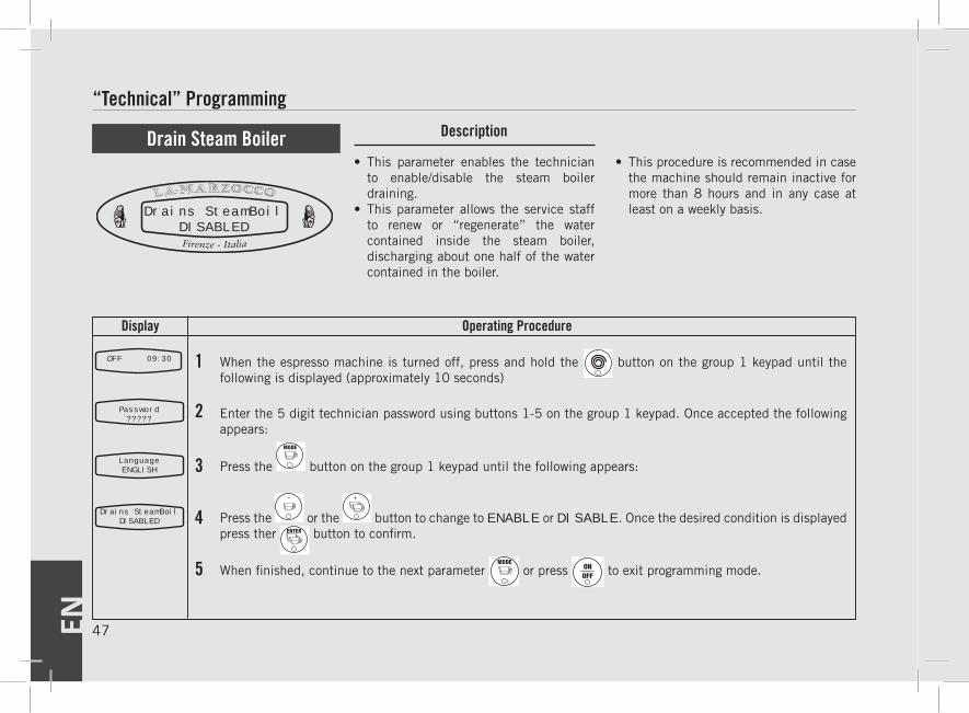
DescriptionProgramming ModeDrain Steam Boiler• This parameter enables the technician
to enable/disable the steam boiler draining.
• This parameter allows the service staff to renew or “regenerate” the water contained inside the steam boiler, discharging about one half of the water contained in the boiler.
Drains SteamBoilDISABLED
When the espresso machine is turned off, press and hold the button on the group 1 keypad until the following is displayed (approximately 10 seconds)
Enter the 5 digit technician password using buttons 1-5 on the group 1 keypad. Once accepted the following appears:
Press the button on the group 1 keypad until the following appears:
Press the or the button to change to ENABLE or DISABLE. Once the desired condition is displayed press ther button to confirm.
When finished, continue to the next parameter or press to exit programming mode.
1
2
4
3
5
• This procedure is recommended in case the machine should remain inactive for more than 8 hours and in any case at least on a weekly basis.
OFF 09:30
Password?????
LanguageENGLISH
Drains SteamBoilDISABLED
“Technical” Programming
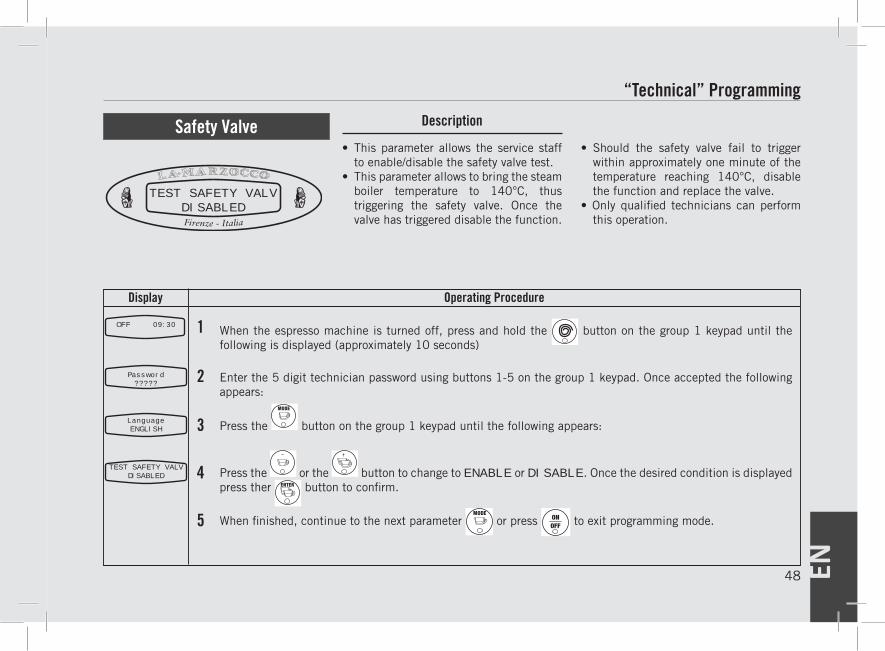
EN48
Display Operating Procedure
DescriptionSafety Valve• This parameter allows the service staff
to enable/disable the safety valve test. • This parameter allows to bring the steam
boiler temperature to 140°C, thus triggering the safety valve. Once the valve has triggered disable the function.
TEST SAFETY VALVDISABLED
When the espresso machine is turned off, press and hold the button on the group 1 keypad until the following is displayed (approximately 10 seconds)
Enter the 5 digit technician password using buttons 1-5 on the group 1 keypad. Once accepted the following appears:
Press the button on the group 1 keypad until the following appears:
Press the or the button to change to ENABLE or DISABLE. Once the desired condition is displayed press ther button to confirm.
When finished, continue to the next parameter or press to exit programming mode.
1
2
4
3
5
• Should the safety valve fail to trigger within approximately one minute of the temperature reaching 140°C, disable the function and replace the valve.
• Only qualified technicians can perform this operation.
OFF 09:30
Password?????
LanguageENGLISH
TEST SAFETY VALVDISABLED
“Technical” Programming
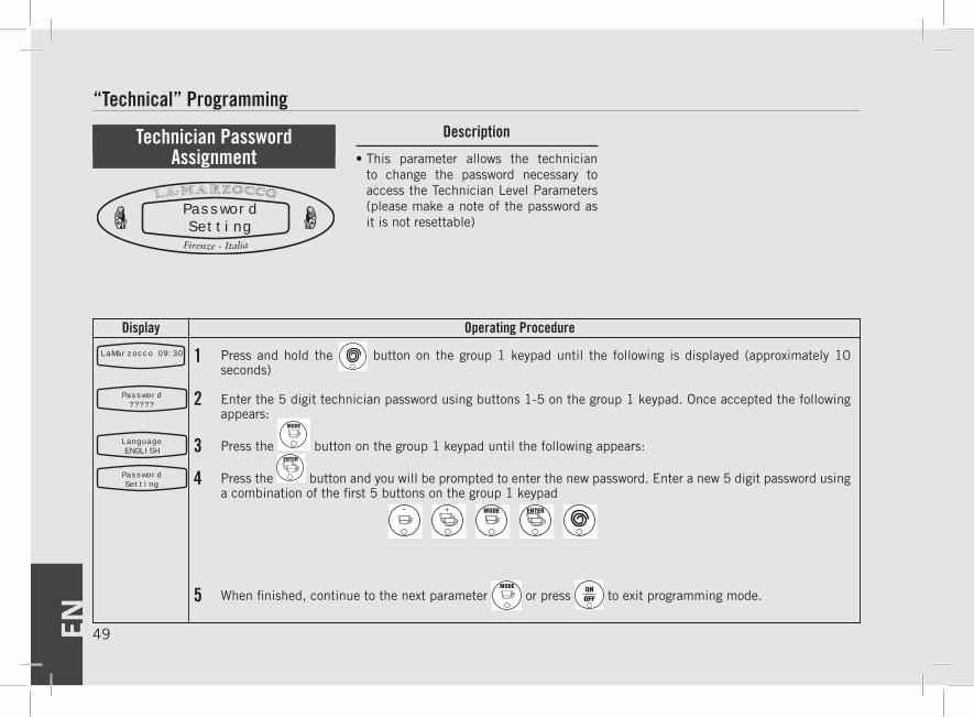
EN 49
Display Operating Procedure
DescriptionProgramming Mode
1LaMarzocco 09:30
2
3
4
5
Press and hold the button on the group 1 keypad until the following is displayed (approximately 10 seconds)
Enter the 5 digit technician password using buttons 1-5 on the group 1 keypad. Once accepted the following appears:
Press the button on the group 1 keypad until the following appears:
Press the button and you will be prompted to enter the new password. Enter a new 5 digit password using a combination of the first 5 buttons on the group 1 keypad
When finished, continue to the next parameter or press to exit programming mode.
• This parameter allows the technician to change the password necessary to access the Technician Level Parameters (please make a note of the password as it is not resettable)
Technician Password Assignment
PasswordSetting
Password?????
LanguageENGLISH
PasswordSetting
“Technical” Programming
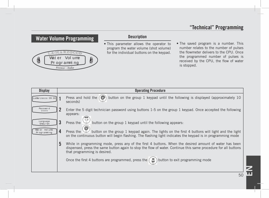
EN50
Display Operating Procedure
Description
1LaMarzocco 09:30
2
3
4
Press and hold the button on the group 1 keypad until the following is displayed (approximately 10 seconds)
Enter the 5 digit technician password using buttons 1-5 on the group 1 keypad. Once accepted the following appears:
Press the button on the group 1 keypad until the following appears:
Press the button on the group 1 keypad again. The lights on the first 4 buttons will light and the light on the continuous button will begin flashing. The flashing light indicates the keypad is in programming mode
While in programming mode, press any of the first 4 buttons. When the desired amount of water has been dispensed, press the same button again to stop the flow of water. Continue this same procedure for all buttons that programming is desired.
Once the first 4 buttons are programmed, press the button to exit programming mode
“Technical” Programming
• This parameter allows the operator to program the water volume (shot volume) for the individual buttons on the keypad.
• The saved program is a number. This number relates to the number of pulses the flowmeter delivers to the CPU. Once the programmed number of pulses is received by the CPU, the flow of water is stopped.
Water Volume Programming
Water VolumeProgramming
Water VolumeProgramming
Password?????
LanguageENGLISH
5
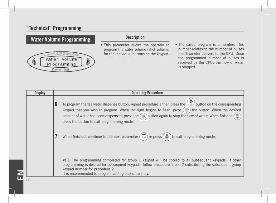
EN 51
Display Operating Procedure
DescriptionProgramming Mode
6
7
To program the tea water dispense button, repeat procedure 1 then press the button on the corresponding
keypad that you wish to program. When the light begins to flash, press the button. When the desired
amount of water has been dispensed, press the
button again to stop the flow of water. When finished
press the button to exit programming mode.
When finished, continue to the next parameter or press to exit programming mode.
“Technical” Programming
• This parameter allows the operator to program the water volume (shot volume) for the individual buttons on the keypad.
• The saved program is a number. This number relates to the number of pulses the flowmeter delivers to the CPU. Once the programmed number of pulses is received by the CPU, the flow of water is stopped.
Water Volume Programming
Water VolumeProgramming
NOTE: The programming completed for group 1 keypad will be copied to all subsequent keypads. If other programming is desired for subsequent keypads, follow procedure 1 and 2 substituting the subsequent group keypad number for procedure 2.It is recommended to program each group separately.
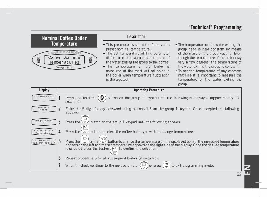
EN52
Display Operating Procedure
Description
1LaMarzocco 09:30
2
3
4
5
67
Press and hold the button on the group 1 keypad until the following is displayed (approximately 10 seconds):
Enter the 5 digit factory password using buttons 1-5 on the group 1 keypad. Once accepted the following appears:
Press the button on the group 1 keypad until the following appears:
Press the button to select the coffee boiler you wish to change temperature.
Press the or the button to change the temperature on the displayed boiler. The measured temperature appears on the left and the set temperature appears on the right side of the display. Once the desired temperature is selected press the button to confirm the selection.
Repeat procedure 5 for all subsequent boilers (if installed).
When finished, continue to the next parameter or press to exit programming mode.
• This parameter is set at the factory at a preset nominal temperature.
• The set temperature of this parameter differs from the actual temperature of the water exiting the group to the coffee.
• The temperature of the boiler is measured at the most critical point in the boiler when temperature fluctuation is the greatest.
• The temperature of the water exiting the group head is held constant by means of the mass of the group casting. Even though the temperature of the boiler may vary a few degrees, the temperature of the water exiting the group is constant.
• To set the temperature of any espresso machine it is important to measure the temperature of the water exiting the group.
Nominal Coffee Boiler Temperature
Password?????
Groups Number3
Coffee BoilersTemperatures
Coffee Boiler 1202.5 F 202.6 F
Cofee BoilersTemperatures
“Technical” Programming
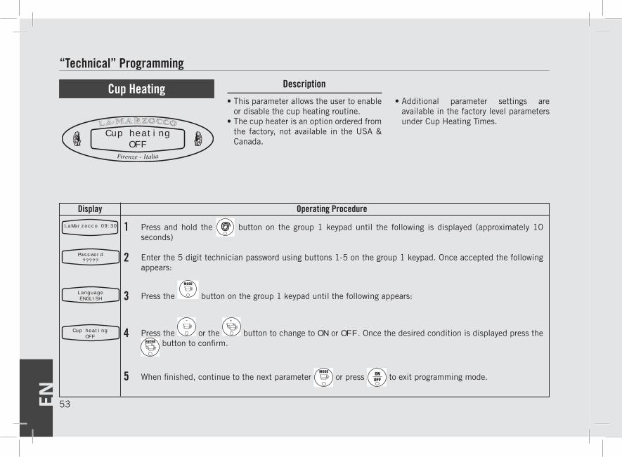
EN 53
Display Operating Procedure
DescriptionProgramming Mode
1LaMarzocco 09:30
4
Press and hold the button on the group 1 keypad until the following is displayed (approximately 10 seconds)
Enter the 5 digit technician password using buttons 1-5 on the group 1 keypad. Once accepted the following appears:
Press the button on the group 1 keypad until the following appears:
Press the or the button to change to ON or OFF. Once the desired condition is displayed press the button to confirm.
When finished, continue to the next parameter or press to exit programming mode.
“Technical” Programming
• This parameter allows the user to enable or disable the cup heating routine.
• The cup heater is an option ordered from the factory, not available in the USA & Canada.
• Additional parameter settings are available in the factory level parameters under Cup Heating Times.
Cup Heating
Cup heatingOFF
Cup heatingOFF
2
3
Password?????
LanguageENGLISH
5
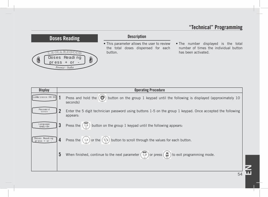
EN54
Display Operating Procedure
Description
1LaMarzocco 09:30
4
Press and hold the button on the group 1 keypad until the following is displayed (approximately 10 seconds)
Enter the 5 digit technician password using buttons 1-5 on the group 1 keypad. Once accepted the following appears:
Press the button on the group 1 keypad until the following appears:
Press the or the button to scroll through the values for each button.
When finished, continue to the next parameter or press to exit programming mode.
“Technical” Programming
• This parameter allows the user to review the total doses dispensed for each button.
• The number displayed is the total number of times the individual button has been activated.
Doses Reading
Doses Readingpress + or -
Doses Readingpress + or -
5
2
3
Password?????
LanguageENGLISH
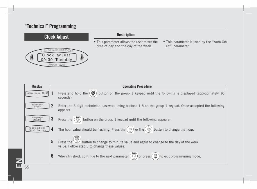
EN 55
Display Operating Procedure
DescriptionProgramming Mode
1LaMarzocco 09:30
4
5
Press and hold the button on the group 1 keypad until the following is displayed (approximately 10 seconds)
Enter the 5 digit technician password using buttons 1-5 on the group 1 keypad. Once accepted the following appears:
Press the button on the group 1 keypad until the following appears:
The hour value should be flashing. Press the or the button to change the hour.
Press the button to change to minute value and again to change to the day of the weekvalue. Follow step 3 to change these values.
When finished, continue to the next parameter or press to exit programming mode.
“Technical” Programming
• This parameter allows the user to set the time of day and the day of the week.
• This parameter is used by the “Auto On/Off” parameter
Clock Adjust
Clock adjust09:30 Tuesday
Clock adjust09:30 Tuesday
6
2
3
Password?????
LanguageENGLISH
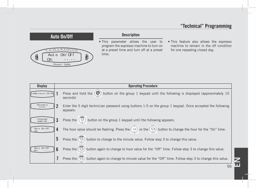
EN56
Display Operating Procedure
Description
1LaMarzocco 09:30
2
3
4
5
6
7
Press and hold the button on the group 1 keypad until the following is displayed (approximately 10 seconds)
Enter the 5 digit technician password using buttons 1-5 on the group 1 keypad. Once accepted the following appears:
Press the button on the group 1 keypad until the following appears:
The hour value should be flashing. Press the or the button to change the hour for the “On” time.
Press the button to change to the minute value. Follow step 3 to change this value.
Press the button again to change to hour value for the “Off” time. Follow step 3 to change this value.
Press the button again to change to minute value for the “Off” time. Follow step 3 to change this value.
“Technical” Programming
• This parameter allows the user to program the espresso machine to turn on at a preset time and turn off at a preset time.
• This feature also allows the espresso machine to remain in the off condition for one repeating closed day.
Auto On/Off
Auto On/OffOn: --.--
Auto On/OffOn: --.--
Auto On/OffOff: --.--
Password?????
LanguageENGLISH
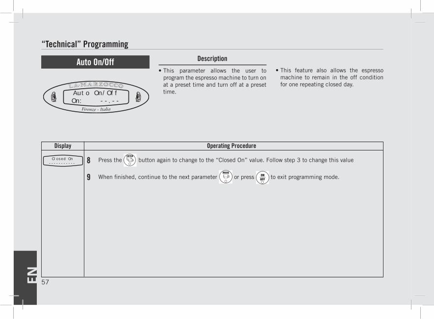
EN 57
Display Operating Procedure
DescriptionProgramming Mode
8 Press the button again to change to the “Closed On” value. Follow step 3 to change this value
When finished, continue to the next parameter or press to exit programming mode.
“Technical” Programming
• This parameter allows the user to program the espresso machine to turn on at a preset time and turn off at a preset time.
• This feature also allows the espresso machine to remain in the off condition for one repeating closed day.
Auto On/Off
Auto On/OffOn: --.--
Closed On-----------
9
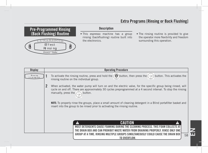
EN58
Display Operating Procedure
Description
1
2
To activate the rinsing routine, press and hold the button, then press the button. This activates the rinsing routine on the individual group.
When activated, the water pump will turn on and the electric valve, for the specific group being rinsed, will cycle on and off. There are approximately 30 cycles preprogrammed at a 4 second interval. To stop the rinsing manually, press the button.
NOTE: To properly rinse the groups, place a small amount of cleaning detergent in a Blind portafilter basket and insert into the group to be rinsed prior to activating the rinsing routine.
Extra Programs [Rinsing or Back Flushing]
• This espresso machine has a group rinsing (backflushing) routine built into the electronics.
• The rinsing routine is provided to give the operator more flexibility and freedom surrounding this operation.
Pre-Programmed Rinsing (Back Flushing) Routine
EffectRinsing
Rinsingin-progress
MOST DETERGENTS CAUSE FOAMING DURING THE CLEANING PROCESS. THIS FOAM COLLECTS AT THE DRAIN BOX AND CAN PROHIBIT WASTE WATER FROM DRAINING PROPERLY. RINSE ONLY ONE GROUP AT A TIME. RINSING MULTIPLE GROUPS SIMULTANEOUSLY COULD CAUSE THE DRAIN BOX
TO OVERFLOW.
CAUTION
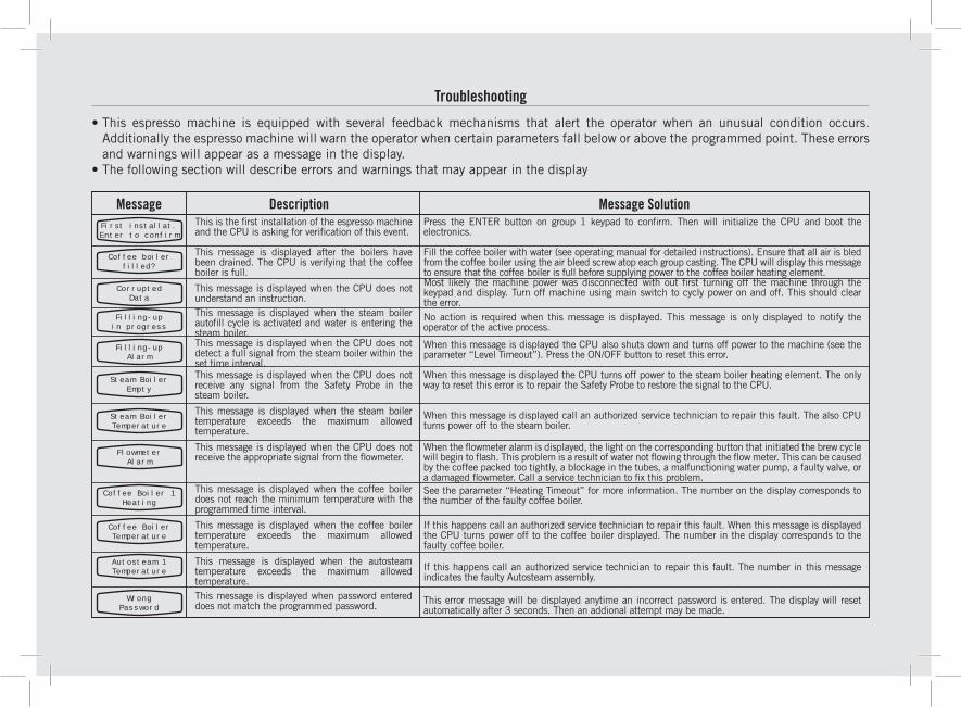
Troubleshooting
Description Message SolutionMessageThis is the first installation of the espresso machine and the CPU is asking for verification of this event.
This message is displayed after the boilers have been drained. The CPU is verifying that the coffee boiler is full.
This message is displayed when the CPU does not understand an instruction.This message is displayed when the steam boiler autofill cycle is activated and water is entering the steam boiler.This message is displayed when the CPU does not detect a full signal from the steam boiler within the set time interval.This message is displayed when the CPU does not receive any signal from the Safety Probe in the steam boiler.
This message is displayed when the steam boiler temperature exceeds the maximum allowed temperature.
This message is displayed when the CPU does not receive the appropriate signal from the flowmeter.
This message is displayed when the coffee boiler does not reach the minimum temperature with the programmed time interval.
This message is displayed when the coffee boiler temperature exceeds the maximum allowed temperature.
This message is displayed when the autosteam temperature exceeds the maximum allowed temperature.This message is displayed when password entered does not match the programmed password.
Press the ENTER button on group 1 keypad to confirm. Then will initialize the CPU and boot the electronics.
Fill the coffee boiler with water (see operating manual for detailed instructions). Ensure that all air is bled from the coffee boiler using the air bleed screw atop each group casting. The CPU will display this message to ensure that the coffee boiler is full before supplying power to the coffee boiler heating element.Most likely the machine power was disconnected with out first turning off the machine through the keypad and display. Turn off machine using main switch to cycly power on and off. This should clear the error.No action is required when this message is displayed. This message is only displayed to notify the operator of the active process.
When this message is displayed the CPU also shuts down and turns off power to the machine (see the parameter “Level Timeout”). Press the ON/OFF button to reset this error.
When this message is displayed the CPU turns off power to the steam boiler heating element. The only way to reset this error is to repair the Safety Probe to restore the signal to the CPU.
When this message is displayed call an authorized service technician to repair this fault. The also CPU turns power off to the steam boiler.
When the flowmeter alarm is displayed, the light on the corresponding button that initiated the brew cycle will begin to flash. This problem is a result of water not flowing through the flow meter. This can be caused by the coffee packed too tightly, a blockage in the tubes, a malfunctioning water pump, a faulty valve, or a damaged flowmeter. Call a service technician to fix this problem.See the parameter “Heating Timeout” for more information. The number on the display corresponds to the number of the faulty coffee boiler.
If this happens call an authorized service technician to repair this fault. When this message is displayed the CPU turns power off to the coffee boiler displayed. The number in the display corresponds to the faulty coffee boiler.
If this happens call an authorized service technician to repair this fault. The number in this message indicates the faulty Autosteam assembly.
This error message will be displayed anytime an incorrect password is entered. The display will reset automatically after 3 seconds. Then an addional attempt may be made.
• This espresso machine is equipped with several feedback mechanisms that alert the operator when an unusual condition occurs. Additionally the espresso machine will warn the operator when certain parameters fall below or above the programmed point. These errors and warnings will appear as a message in the display.
• The following section will describe errors and warnings that may appear in the display
First installat.Enter to confirm
Coffee boilerfilled?
CorruptedData
Filling-upin progress
Filling-upAlarm
Steam BoilerEmpty
Steam BoilerTemperature
FlowmeterAlarm
Coffee Boiler 1Heating
Coffee BoilerTemperature
Autosteam 1Temperature
WrongPassword
EE - Table of Contents
EE - Table of Contents
EE Programming Introduction page 61
Accessing Programming Mode page 62
Coffee Boiler Temperature (example description for all parameters) page 63
EN
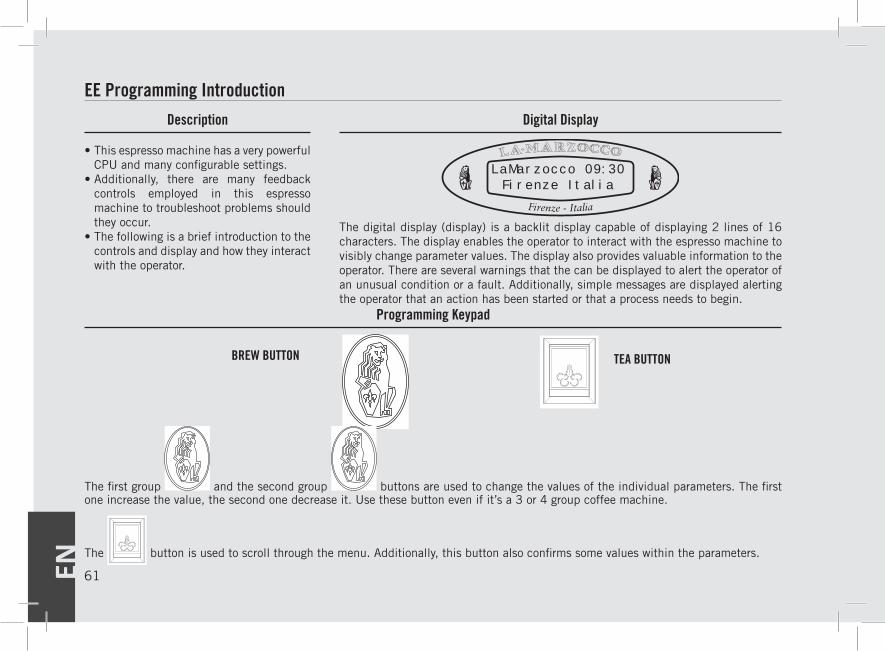
Description
EE Programming Introduction
• This espresso machine has a very powerful CPU and many configurable settings.
• Additionally, there are many feedback controls employed in this espresso machine to troubleshoot problems should they occur.
• The following is a brief introduction to the controls and display and how they interact with the operator.
Digital Display
Programming Keypad
LaMarzocco 09:30Firenze Italia
The digital display (display) is a backlit display capable of displaying 2 lines of 16 characters. The display enables the operator to interact with the espresso machine to visibly change parameter values. The display also provides valuable information to the operator. There are several warnings that the can be displayed to alert the operator of an unusual condition or a fault. Additionally, simple messages are displayed alerting the operator that an action has been started or that a process needs to begin.
BREW BUTTON TEA BUTTON
The first group and the second group buttons are used to change the values of the individual parameters. The first one increase the value, the second one decrease it. Use these button even if it’s a 3 or 4 group coffee machine.
The button is used to scroll through the menu. Additionally, this button also confirms some values within the parameters.
EN 61
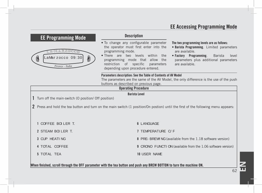
EN62
Description
1
2
Operating Procedure
EE Accessing Programming Mode
• To change any configurable parameter the operator must first enter into the programming mode.
• There are two levels within the programming mode that allow the restriction of specific parameters depending upon procedure entered.
Parameters description: See the Table of Contents of AV ModelThe parameters are the same of the AV Model, the only difference is the use of the push buttons as described on previous page.
The two programming levels are as follows:• Barista Programming. Limited parameters
are available.• Factory Programming. Barista level
parameters plus additional parameters are available.
EE Programming Mode
LaMarzocco 09:30
When finished, scroll through the OFF parameter with the tea button and push any BREW BOTTON to turn the machine ON.
Barista LevelTurn off the main-switch (O position/ Off position)
Press and hold the tea button and turn on the main switch (1 position/On postion) until the first of the following menu appears:
1 COFFEE BOILER T.
2 STEAM BOILER T.
3 CUP HEATING
4 TOTAL COFFEE
5 TOTAL TEA
6 LANGUAGE
7 TEMPERATURE C/F
8 PRE-BREWING (available from the 1.18 software version)
9 CRONO FUNCTION (available from the 1.06 software version)
10 USER NAME
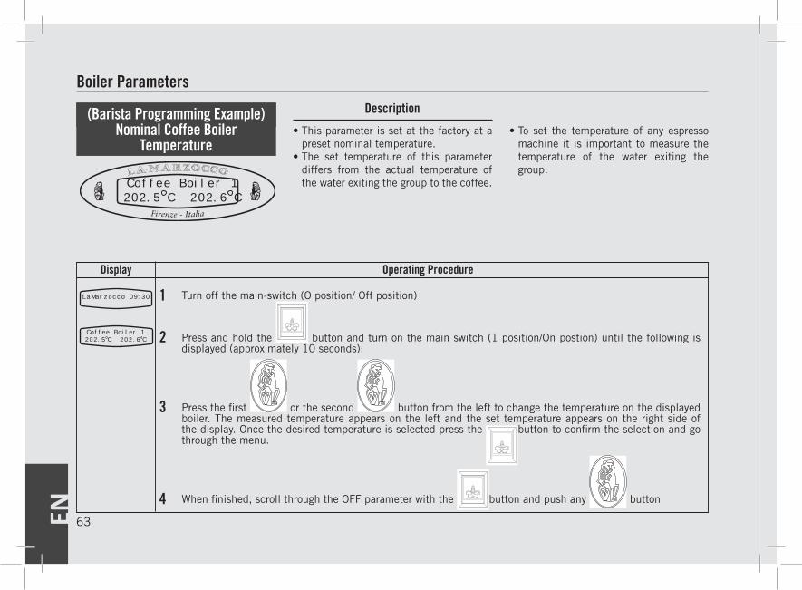
63EN
Programming Mode Description
Operating ProcedureDisplay
1LaMarzocco 09:30
2
3
4
Turn off the main-switch (O position/ Off position)
Press and hold the button and turn on the main switch (1 position/On postion) until the following is displayed (approximately 10 seconds):
Press the first or the second button from the left to change the temperature on the displayed boiler. The measured temperature appears on the left and the set temperature appears on the right side of the display. Once the desired temperature is selected press the
button to confirm the selection and go through the menu.
When finished, scroll through the OFF parameter with the button and push any button
Boiler Parameters
• This parameter is set at the factory at a preset nominal temperature.
• The set temperature of this parameter differs from the actual temperature of the water exiting the group to the coffee.
• To set the temperature of any espresso machine it is important to measure the temperature of the water exiting the group.
(Barista Programming Example) Nominal Coffee Boiler
Temperature
Coffee Boiler 1202.5 C 202.6 C
Coffee Boiler 1202.5 C 202.6 C
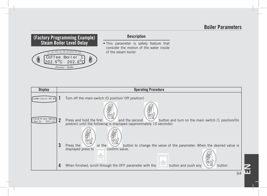
EN64
Display Operating Procedure
Description
1LaMarzocco 09:30
2
3
4
Turn off the main-switch (O position/ Off position)
Press and hold the first and the second button and turn on the main switch (1 position/On postion) until the following is displayed (approximately 10 seconds):
Press the or the button to change the value of the parameter. When the desired value is displayed press to confirm value.
When finished, scroll through the OFF parameter with the button and push any button
Boiler Parameters
• This parameter is safety feature that consider the motion of the water inside of the steam boiler.
(Factory Programming Example) Steam Boiler Level Delay
LevelProbe DelayTon:2s Toff:2s
Coffee Boiler 1202.5 C 202.6 C