manual motor starter guide m ms, ms and ms!
TRANSCRIPT

— MANUAL MOTOR STARTER GUIDE
Manual motor starter
MS116, MS132 and MS165

MANUAL MOTOR STARTER GUIDE
FEBRUARY 20 2/85
_ Foreword ABB is a pioneering technology leader in electrification products, robotics and motion, and industrial automation,
serving customers in utilities, industry and transport and infrastructure globally. Continuing a history of innova-
tion spanning more than 130 years, ABB today is writing the future of industrial digitalization with two clear value
propositions: bringing electricity from any power plant to any plug and automating industries from natural re-
sources to finished products.
ABB offers a wide range of manual motor starters (MMS), also known as motor protective circuit-breakers. We realize
that with all the standards, rules, listings, and codes, the what, when, where, why and how of manual motor starters
can appear complex.
The following information is provided to aid in the proper use of ABB manual motor starters and all their capabilities.
This guide is written with the aim of being a general guide for people working with manual motor starter applica-
tions, but also for those who are simply interested in learning more about the products, standards, and applications.
All these are relevant for European applications (based on IEC) and North American applications (UL / CSA).
The guide is neither a complete technical guide nor a manual for all types of ABB’s motor starting solutions. It is a
complement to the catalog, data sheets and brochures available for our products and will provide a general overview
of what to consider when working with manual motor starters.
More information on manual motor starters as well as other ABB products is available at:
https://new.abb.com/low-voltage/products/motor-protection.
All the information provided in this guide is only general and each individual application must be handled as a spe-
cific case. Be sure to always follow all national and local installation regulations/codes for your specific application.
_ Safety and warnings
This symbol in conjunction with the signal word "DANGER" indicates an imminent electrical haz-
ard. Failure to observe the related safety note may cause personnel injury or death or
equipment damages.
This symbol in conjunction with the signal word "WARNING" indicates a potentially dangerous
situation. Failure to observe the related safety note may cause personnel injury or death or
equipment damages.
This symbol indicates a safety note: “ATTENTION! Hazardous voltage!”
Installation by a certified service engineer only.”
This symbol in conjunction with the signal word "NOTE" indicates operator tips, particularly
useful or important information for the use of the product. This symbol and wording do not in-
dicate a dangerous situation.
This symbol indicates a compulsory action: “Reading the instruction manual/booklet before
starting work or before operating equipment or machinery.
Recycle.
Do not dispose with ordinary trash.
MANUAL MOTOR STARTER GUIDE
FEBRUARY 20 3/85
_ Table of Contents
Foreword ....................................................................................................................................................................................... 2
1. Standards and approvals for manual motor starters ......................................................................................................... 8 1.1 European directives applicable for manual motor starters .............................................................................................. 8 1.2 CE Marking ................................................................................................................................................................................. 8 1.3 Standards for North America ................................................................................................................................................. 8 1.4 CCC (China Compulsory Certification) ................................................................................................................................. 9 1.5 Other local approvals based on IEC-standard .................................................................................................................... 9 1.6 Marine approvals ...................................................................................................................................................................... 9 1.7 Potentially explosive atmospheres (ATEX)........................................................................................................................... 9
1.7.1 International IECEx System ............................................................................................................................................ 9 1.7.2 IECEx Conformity Mark System ..................................................................................................................................... 9 1.7.5 Equipment categories .................................................................................................................................................... 11 1.7.6 Equipment protection levels (EPL) .............................................................................................................................. 11 1.7.7 Select the device type according to the zone and category/EPL .......................................................................... 11 1.7.8 Manual motor starters in potentially explosive atmospheres ............................................................................... 11
1.8 Applied standards ................................................................................................................................................................... 12
2. General product overview .................................................................................................................................................... 13 2.1 Basic function .......................................................................................................................................................................... 13
2.1.1 Release (tripping element) ............................................................................................................................................ 14 2.1.2 Time-current characteristics (tripping characteristics) ......................................................................................... 14 2.1.3 Overload protection ....................................................................................................................................................... 15 2.1.4 Overload trip classes ..................................................................................................................................................... 15 2.1.5 Short-circuit protection ................................................................................................................................................ 15 2.1.6 Phase loss sensitivity ..................................................................................................................................................... 16 2.1.7 Single-phase and direct current (DC) loads ............................................................................................................... 16
2.2 Terms and ratings ................................................................................................................................................................... 16 2.2.1 Rated operational voltage (Ue) .................................................................................................................................... 16 2.2.2 Rated short-circuit making capacity (Icm) ................................................................................................................ 16 2.2.3 Rated short-circuit breaking capacity ........................................................................................................................ 16 2.2.3.1 Rated ultimate short-circuit breaking capacity (Icu) acc. to IEC / EN 60947-2 ............................................... 17 2.2.3.2 Rated service short-circuit breaking capacity (Ics) acc. to IEC / EN 60947-2 ................................................. 17 2.2.3.3 What are the difference between the rated ultimate short-circuit breaking capacity (Icu)
and rated service short-circuit breaking capacity (Ics) ................................................................................................... 17 2.2.4 Rated short-time withstand current (Icw) ................................................................................................................ 17 2.2.5 Selectivity categories .................................................................................................................................................... 17 2.2.6 Ambient air temperature compensation ................................................................................................................... 17 2.2.7 Temperature rise of the manual motor starter ......................................................................................................... 18 2.2.8 Trip-free mechanism ..................................................................................................................................................... 18 2.2.9 Phase loss sensitivity .................................................................................................................................................... 19 2.2.10 Mechanical and electrical durability ......................................................................................................................... 19
2.3 Switch and breaker types ...................................................................................................................................................... 19 2.3.1 Motor protection circuit-breaker ................................................................................................................................. 19 2.3.2 Circuit-breaker ............................................................................................................................................................... 20 2.3.3 Load switch .................................................................................................................................................................... 20 2.3.4 Disconnect switch ........................................................................................................................................................ 20
2.4 Product offering ...................................................................................................................................................................... 21 22.4.1 MS116 .............................................................................................................................................................................. 22 2.4.2 MS132 ............................................................................................................................................................................... 22 2.4.2.1 MS132-K ......................................................................................................................................................................... 22 2.4.3 MS165 ............................................................................................................................................................................... 22 2.4.4 MS132-T and MS132-KT ................................................................................................................................................. 22

MANUAL MOTOR STARTER GUIDE
FEBRUARY 20 4/85
2.4.5 MO132 and MO165 ......................................................................................................................................................... 22 2.4.6 Accessories and enclosures .........................................................................................................................................23
3. Load types .............................................................................................................................................................................. 28 3.1 General use and heaters ........................................................................................................................................................ 29 3.2 Motors ...................................................................................................................................................................................... 30
3.2.1 About motors .................................................................................................................................................................. 31 3.2.2 Squirrel cage motors ..................................................................................................................................................... 31 3.2.3 International motor efficiency standards and regulations ................................................................................... 32 3.2.4 Rating plate of a motor ................................................................................................................................................ 36 3.2.5 Voltage ............................................................................................................................................................................ 36 3.2.6 Current ............................................................................................................................................................................. 37 3.2.7 Power factor ................................................................................................................................................................... 38 3.2.8 Torque ............................................................................................................................................................................. 38 3.2.9 Starting methods .......................................................................................................................................................... 39
3.3 Hermetic refrigerant compressor motors ....................................................................................................................... 39 3.4 Lamps and lighting loads ..................................................................................................................................................... 40 3.5 Transformers .......................................................................................................................................................................... 40
3.5.1 Primary-side protection of transformers ................................................................................................................. 40 3.5.2 Secondary-side protection of transformers. ........................................................................................................... 40
3.6 Capacitors ................................................................................................................................................................................ 41
4. Environmental and application-specific factors .............................................................................................................. 41 4.1 Ambient air temperature compensation and derating .................................................................................................... 41 4.2 Duty cycles and restarting .................................................................................................................................................... 41 4.3 Frequencies and direct current (DC) .................................................................................................................................. 43
5. Selection criteria .................................................................................................................................................................. 44 5.1 Sizing manual motor starters for motor applications .................................................................................................... 44 5.2 Selected Optimized Coordination (SOC) ........................................................................................................................... 44
6. Installation and commissioning .......................................................................................................................................... 46 6.1 Mounting .................................................................................................................................................................................. 46
6.1.1 Mounting position and minimum distances ............................................................................................................ 46 6.2 Connection .............................................................................................................................................................................. 47
6.2.1 Connection Types .......................................................................................................................................................... 47 6.2.2 Connection cross sections .......................................................................................................................................... 47
6.3 Motor current setting procedure ........................................................................................................................................ 48 6.4 Overload trip test .................................................................................................................................................................. 48 6.5 Restart after tripping ............................................................................................................................................................ 49 6.6 How to lock a manual starter by disconnecting .............................................................................................................. 49 6.7 Installation instructions ........................................................................................................................................................ 50 6.8 2D drawings and 3D models ................................................................................................................................................ 50
7. Requierements for North America ..................................................................................................................................... 50 7.1 General certification in North America ............................................................................................................................... 50
7.1.1 Product certification marks .......................................................................................................................................... 51 7.1.2 Joint U.S.-Canadian approvals ...................................................................................................................................... 51 7.1.3 Relevant North American standards ........................................................................................................................... 51 7.1.4 Global harmonization efforts ...................................................................................................................................... 52 7.1.5 Categorizing manual motor starters ......................................................................................................................... 52 7.1.6 Selecting the right Short Circuit Current Ratings (SCCR) level for your UL application .................................. 53
7.2 North American voltage supply networks and load types.............................................................................................. 54 7.2.1 North American voltages .............................................................................................................................................. 54 7.2.2 Three-phase network configurations ........................................................................................................................ 55 7.2.3 Straight vs. slash voltage ratings ............................................................................................................................... 55 7.2.4 Short-circuit current ratings ....................................................................................................................................... 56 7.2.5 Components requiring short-circuit current ratings .............................................................................................. 56

MANUAL MOTOR STARTER GUIDE
FEBRUARY 20 5/85
7.2.6 Standard (low) fault ratings - Mandatory ................................................................................................................. 56 7.2.7 High fault ratings - Optional ........................................................................................................................................ 56 7.2.8 Defined acceptance criteria ........................................................................................................................................ 57 7.2.9 Calculating the available fault current for a facility ................................................................................................ 57 7.2.10 Additional current limiting devices .......................................................................................................................... 59
7.3 Defining branch circuits ........................................................................................................................................................ 59 7.4 Functional requirements for all motor branch circuits ................................................................................................... 62
7.4.1 Disconnect means for the motor and branch circuit .............................................................................................. 63 7.4.2 Short-circuit and ground-fault protection for the motor and branch circuit .................................................... 63 7.4.3 Motor control means .................................................................................................................................................... 63 7.4.4 Overload protection for the motor and branch circuit .......................................................................................... 63 7.4.3 Local motor disconnect ............................................................................................................................................... 63
7.5 Product offering for north American applications .......................................................................................................... 64 7.6 Suitable applications for manual motor starters for North America ........................................................................... 65
7.6.1 Defining Manual Motor Controllers (NLRV) .............................................................................................................. 65 7.6.2 Defining Combination Motor Controllers (NKJH) .................................................................................................... 72
8. Glossary .................................................................................................................................................................................. 76
9. Appendix ................................................................................................................................................................................. 78 A.1 Group installation worksheet .............................................................................................................................................. 78 A.2 Flowchart for selecting the right Short-circuit Current Ratings (SCCR) level for your UL application ................. 80 A.3 Frequently asked questions (FAQ) ...................................................................................................................................... 81 A.4 Motor rated operational powers and currents ................................................................................................................ 82

MANUAL MOTOR STARTER GUIDE
FEBRUARY 20 6/85
—
Introduction
The world industry and commerce are facing an energy
challenge. The global demand for energy is rising steadily.
At the same time, pressures to reduce energy consumption,
to lower carbon dioxide (CO2) emissions and provide secure
power supplies are becoming ever stronger.
It has been estimated that around 300 million electric motors
are installed today (with an annual growth rate of more than
5 percent). Furthermore, it has been estimated that electric
motors account for about 65 percent of the electricity
consumed in industrial applications.
ABB is not only a long-standing advocate of the need for high
efficiency in motors and its policy is to offer high-efficiency
motors as standard but also making sure that motors and
users are properly protected.

MANUAL MOTOR STARTER GUIDE
FEBRUARY 20 7/85
_
The greatest risk for motor applications is overheating. Ab-
normal temperature rises can be caused by overloads,
electrical faults, cooling problems, wrong operating param-
eters or improper operating conditions.
Examples of such overloads include
Overloads caused by over current
– locked rotors
– long starting or braking times
– changes of the friction ratio of the operated engine
– non-permissible intermittent operations
– long-term overloads in continuous operation
– undervoltage
Supply problems, which could cause unsymmetrical over-currents
– earth faults
– phase loss
– phase unbalance on the supply side
– interwinding or interturn fault within the motor
Cooling problems
– reduced convection currents due to dust or dirt
– mounting position of the motor: good circulation of air prevents heat build-up
– low air density due to incorrect installation and altitude environmental parameters

MANUAL MOTOR STARTER GUIDE
FEBRUARY 20 8/85
_ 1. Standards and approvals for manual motor starters
All ABB low voltage devices are developed and manufactured according to the rules set out in the IEC (International
Electrotechnical Commission). The IEC issues publications that act as a basis for the world market. The applicable
standard is the IEC 60947 series for Europe and UL 60947 for North America. All devices are built according to this
standard and in most countries, they are not subject to any other tests besides the manufacturer responsibility. In
some countries, the law requires additional certification.
_ 1.1 European directives applicable for manual motor starters
There are essential European directives:
- Low Voltage Directive 2014/35/EU
Concerns electrical equipment from 50 to 1000 V AC and from 75 to 1500 V DC.
- RoHS Directive 2011/65/EU
Restriction of the use of Certain Hazardous Substances in Electronic and Electrical Equipment
- ATEX Directive 2014/34/EU
The European Parliament and of the Council on the harmonization of the laws of the Member States relating to equipment and protective systems intended for use in potentially explosive atmospheres
− WEEE Directive 2012/19/EU
Directive of the European Parliament and of the Council of 4 July 2012 on waste electrical and electronic equipment (Waste Electrical and Electronic Equipment Directive)
_ 1.2 CE Marking
When a product is verified according to its applicable EN standard, the product is presumed to fulfil all applicable
directives, e.g., the “Low Voltage Directive 2014/35/EU”, and it is allowed to apply the CE marking on the product.
EN 60947-4-1 is the harmonized standard for manual motor starters and it is identical to IEC 60947-4-1. The same
applies to the EN 60947-2, EN 60947-1 for the accessories the EN60947-5-1
In this case, the CE marking does not cover the “Machinery Directive, Directive 2006/42/EC” which requires a special
verification of the installation of the machine. The manual motor starter is an electrical device, with mainly electrical
risks. It is instead covered by the low voltage directive.
The CE marking is not a quality label, it is proof of conformity to the European Directives concerning the product.
_ 1.3 Standards for North America
Specifications for the north America and Canadian markets are quite similar but differ a lot from IEC standards and
European specifications. In Chapter
7. Requirements for North America, this topic will be described in more detail.
USA - UL Underwriters Laboratories Inc.
Canada - CSA Canadian Standards Association
There are different types of UL certification, including UL listed and UL component recognition. UL listing means that
UL has tested representative samples of the product and determined that it meets UL’s requirements. UL’s compo-
nent recognition service, however, only covers the evaluation of components or materials intended for use in a
complete product or system. All ABB manual motor starters that have UL certification, are UL listed. Manual motor
starters can also be cULus listed, meaning that they are UL listed to US and Canadian safety standards. All the re-
quirements of both UL and CSA are covered by cULus, so the product is then suitable for use in the US and in Canada.

MANUAL MOTOR STARTER GUIDE
FEBRUARY 20 9/85
_ 1.4 CCC (China Compulsory Certification)
Since the manual motor starters standard is listed according to the CCC-regulation in China, it is mandatory to have
the product approved and labelled with a CCC-mark to be allowed to be put on the Chinese market. The Chinese
GB14048.2 and GB14048.4 standard is based on the IEC-standard IEC 60947-2 and IEC 60947-4-1.
_ 1.5 Other local approvals based on IEC-standard
In addition to IEC and UL standards, many countries have their own local certifications. Some examples of the major
ones besides the already mentioned CSA and CCC are listed below:
− EAC – The Eurasian Conformity mark for Russia, Ukraine etc.
− RCM – The Regulatory Compliance Mark for Australian & New Zealand
− NOM – The Norma Oficial Mexicana
− KC – The Korea Certification mark
_ 1.6 Marine approvals
For manual motor starters used on board ships, maritime insurance companies sometimes require different marine
certificates of approvals. Some examples include: DNV GL (Det Norske Veritas together with Germanischer Lloyd), BV
(Bureau Veritas), LR (Lloyds Register EMEA) which are based on the IEC standard, or from ABS (the American Bureau
of Shipping) which is based on UL standards or on some other independent certification organization. Typically, ma-
rine approvals have special requirements regarding shock, vibrations and humidity.
_ 1.7 Potentially explosive atmospheres (ATEX)
Explosive atmospheres occur when flammable gases, mist, vapors or dust are mixed with air. This creates a risk of an
explosion. The amount of a substance needed to create an explosive atmosphere depends on the substance in ques-
tion. The area where this possibility exists is defined as a potentially explosive atmosphere. These atmospheres can
be found throughout industries, from chemical, pharmaceutical, and food, to power, mining and wood processing.
The areas may also be known as “hazardous areas” or “hazardous locations.”
1.7.1 International IECEx System
The IECEx System (http://www.iecex.com/) from the International Electrotechnical Commission, is a voluntary certi-
fication system that verifies compliance with IEC standards related to safety in explosive atmospheres. The IECEx
System covers four main areas:
− Certification of service facilities
− IECEx equipment certification
− Ex marking conformity
− Certification of Personnel Competencies
1.7.2 IECEx Conformity Mark System
In order for equipment to receive a conformity “Ex” marking under the IECEx System, it must obtain a certificate of
conformity. To obtain a certificate of conformity, there must be:
− An accepted IECEx Quality Assessment Report (QAR)
− An accepted IECEx Test Report for type testing (ExTR)
Products with the IECEx conformity mark have received the IECEx Certificate of Conformity, which confirms the
product has the appropriate protection for use in explosive atmospheres and that it has been manufactured under a
system subject to ongoing surveillance by certification bodies. The marking also indicates that the product can be
supplied to the market without the need for additional testing. The exception is the increased safety (EX e) motor
protection type, which must always be tested with the drive it is used with.

MANUAL MOTOR STARTER GUIDE
FEBRUARY 20 10/85
1.7.3 European Directives referred to ATEX
Commonly referred to as ATEX, from the French “ATmosphères EXplosibles”, this European Directives is a combina-
tion of two EU directives: The Worker Protection Directive 1999/92/EC and the Product Directive 2014/34/EU. This
provides guidelines similar to the IECEx system, with a few exceptions, and without the certification of service facili-
ties and certification of personnel competencies. Compliance with the “Essential Health and Safety Requirements”
described in the directives is mandatory within the European Union countries. The easiest way to show compliance is
to follow harmonized standards.
1.7.4 Potentially explosive atmospheres groups, zones, categories and devices
Within industries, all potentially explosive atmospheres are required to have an area classification referred to as the
zone system. The zone system is used all over the world and nowadays also accepted as an alternative system in
North America.
Authorities normally determine the area, but it can also be performed by a third party, a notified body or other ex-
pert. It is the owner’s responsibility to ensure that the classification of their site is performed before suitable
products can be selected and installed at the location.
Globally, a zone system is used to classify potentially explosive areas. The Worker Protection Directive 1999/EC and
the international standards IEC / EN 60079-10-x define these zones. In all cases, zone classification for potentially
explosive atmospheres, zones, categories and devices are the responsibility of the owner of the site where the po-
tentially explosive atmosphere exists.
There are 6 zones:
− Zone 0 (for gas) and 20 (for dust), where there is a continuous presence of an explosive atmosphere.
− Zone 1 (for gas) and 21 (for dust), where there is an occasional occurrence of a potentially explosive atmos-
phere.
− Zone 2 (for gas) and 22 (for dust), where potentially explosive atmospheres can occur by accident, not during
normal operation.
_
Figure 1: Potentially explosive atmosphere groups, zones, categories and devices. “G” = Gas; “D” = Dust

MANUAL MOTOR STARTER GUIDE
FEBRUARY 20 11/85
1.7.5 Equipment categories
Equipment categories are used in the ATEX directive. The category indicates which safety level must be used in each
zone. In zone 0/20, category 1 devices must be used; in zone 1/21, category 2 devices; and in zone 2/22, category 3
devices. Classification into categories is particularly important, because all the inspection, maintenance and repair
duties of the end user will depend on the category of the product/equipment, not on the zone where it is installed.
1.7.6 Equipment protection levels (EPL)
The latest revisions to the IEC and EN standards include the concept of “equipment protection levels” (EPLs), which
identify products according to the ignition risk they might cause. The EPL also considers the potential consequences
of an explosion. For zone 0/20, the equipment protection level required would be “a”; for zone 1/21, it would be “b”;
and for zone 2/22, the level would be “c”.
1.7.7 Select the device type according to the zone and category/EPL
Standard
IEC 60079-0
EN 60079-0
Zone according to
IEC 60079-10-x
EN 60079-10-x
ATEX Directive
2014/34/EU (previously 94/9/EC)
Group EPL Protection level Zones Equipment group Equipment category
I
(Mines)
Ma Very high The zone classification is
not used in mines
I
(Mines)
M1
Mb High M2
II
(Gas)
Ga Very high 0
II
(Surface)
1G
Gb High 1 2G
Gc Enhanced 2 3G
III
(Dust)
Da Very high 20 1D
Db High 21 2D
Dc Enhanced 22 3D _
Table 1: Select the device type according to the zone and category/EPL
1.7.8 Manual motor starters in potentially explosive atmospheres
Manual motor starters (e.g. MS132 and MS165) are authorized under device group II, category (2) in the "G" area (ar-
eas with potentially explosive gas, steam, smoke or air mixtures) and additionally for the "D" area (areas with
combustible dust).
BVS 15 ATEX F 004
II (2) G IECEx BVS 17.0070
II (2) D [Ex]
Manual motor starters are not suitable for installation and/or operation in potentially explosive areas. It is intended
to protect a motor which is installed in the potentially explosive atmosphere. When using the devices in potentially
explosive areas, preventive measures must be taken, e. g., operation within a suitable enclosure.
Notes:
− For explosion-proof applications, the efficiency of the installed protection devices must be verified prior to
commissioning!
− The protection function of the device is the thermal overload protection and protection against short-cir-
cuits in the motor. In case of an overload trip, the motor is switched off by opening the main contacts of the
manual motor starter.
− The safe state is the "tripped state", i.e., turning the handle to the 0-position or trip position.

MANUAL MOTOR STARTER GUIDE
FEBRUARY 20 12/85
_ 1.8 Applied standards
Following standards are used or partly used for ABB’s manual motor starters.
International and European standards
IEC / EN 60947-1 Low-voltage switchgear and controlgear - Part 1: General rules
IEC / EN 60947-2 Low-voltage switchgear and controlgear - Part 2: Circuit-breakers
IEC / EN 60947-4-1 Low-voltage switchgear and controlgear - Part 4-1: Contactors and motor-starters - Elec-
tromechanical contactors and motor-starters
IEC / EN 60947-5-1 Low-voltage switchgear and controlgear - Part 5-1: Control circuit devices and switching
elements - Electromechanical control circuit devices
Standards for north America
UL 60947-4-1
(formerly UL 508) Low-voltage switchgear and controlgear - Part 4-1: Contactors and Motor-Starters - Elec-
tromechanical contactors and motor-starters
UL 60947-4-1A 2nd Ed. - Low-Voltage Switchgear and Controlgear – Part 4-1: Contactors and Motor Start-
ers – Electromechanical Contactors and Motor-Starters
UL 60947-5-1 Low-Voltage Switchgear and Controlgear - Part 5-1: Control Circuit Devices and Switching
Elements - Electromechanical Control Circuit Devices
Standards for Canada
CSA C22.2 No.60947-1
(formerly CSA C22.2 No.14)
Low-voltage switchgear and controlgear - Part 1: General rules
CSA C22.2 No.60947-4-1
(formerly CSA C22.2 No.14)
Low-voltage switchgear and controlgear - Part 4-1: Contactors and motor-starters - Elec-
tromechanical contactors and motor-starters
Standards for China
GB/T14048.2 Low-voltage switchgear and controlgear - Part 2: Circuit-breakers
GB/T14048.4 Low-voltage switchgear and controlgear - Part 4-1: Contactors and motor-starters - Elec-
tromechanical contactors and motor-starters
GB/T14048.5 Low-voltage switchgear and controlgear - Part 5-1: Control circuit devices and switching
element - Electromechanical control circuit devices
Standards for ATEX
IEC / EN 60079-0 Explosive atmospheres - Part 0: Equipment - General requirements
IEC / EN 60079-1 Explosive atmospheres - Part 1: Equipment protection by flameproof enclosures "d"
IEC / EN 60079-7 Explosive atmospheres - Part 7: Equipment protection by increased safety "e"
IEC / EN 60079-31 Explosive atmospheres - Part 31: Equipment dust ignition protection by enclosure "t"”
IEC / EN EN 60079-14 Explosive atmospheres - Part 14: Electrical installations design, selection and erection
_
Table 2: Applied standards for the manual motor starter

MANUAL MOTOR STARTER GUIDE
FEBRUARY 20 13/85
_
2. General product overview
_ 2.1 Basic function
Manual motor starters protect the motor and the installation against short-circuits and overloads. They are three
pole electro-mechanical protection devices with a release for overload protection and short-circuit protection. Fur-
thermore, they provide a disconnect function for safe isolation of the installation and the power supply and the can
be used for switching loads ON and OFF manually.
Figure 2: Basic function shown on MS132
Manual motor starters are approved according IEC / EN 60947-2, IEC / EN 60947-4-1 and UL 60947-4-1A (previously
UL 508). The protection function is realized with the following sub-functions:
− overload protection
− short-circuit protection
− phase loss sensitivity
Upon detection of a fault, the manual motor starter disconnects all phases from the supply, directly isolating the
protected load. In addition, manual motor starters increase the device reliability by reacting quickly, protecting
against damage to the load-side circuits and motor by operating within milliseconds following a short-circuit fault.
The term “manual motor starter” is not directly stated in either standard, with the terms for the UL “Manual Motor
Controller” or “Combination Motor Controller” used as these terms refer to these devices. For the International Elec-
trotechnical Commission (IEC), these devices are referred to as “motor protection circuit-breaker (MPCB)” or simply
“circuit- breakers”.
Other common aliases for a manual motor starter include:
− motor-protective circuit-breakers (MPCB)
− manual motor protectors (MMP)
− manual motor controllers (MMC)
− manual starter protectors (MSP)
− motor circuit protectors (MCP)
− motor protection (MP)
Power terminals
They allow the connection of up to two conductors with different
cross-sections for the main.
ON/OFF handle (operator)
For switching ON and OFF; indication of a possible trip; with inte-
grated shut-off device. Switching on and off must be done quickly and
without interruption.
Current setting dial
The dial makes it easy to set the device to the rated motor current.
Label for marking
TEST-Function
Allows testing of the trigger mechanism.
DIN rail mounting
Allows mounting the device on DIN rails 35x15 mm and 35x7.5 mm.

MANUAL MOTOR STARTER GUIDE
FEBRUARY 20 14/85
2.1.1 Release (tripping element)
Manual motor starters fulfill trip classes in accordance with IEC 60947-4-1 and UL 60947-4-1A. The trip class indicates
the maximum tripping time from a cold state. This tripping time refers to a steady symmetrical three-pole load with
a 7.2x current setting.
Similar to molded case circuit-breakers (MCCB), standard manual motor starters are equipped with two releases:
− An adjustable, inverse time-delay overcurrent release for overload protection
− A fixed, instantaneous release for short-circuit protection
Magnetic only (MO) manual motor starters are equipped with an instantaneous short-circuit release. When com-
bined with an external overload relay, this wiring schematic closely resembles that of conventional combination
starters (e.g. circuit-breaker, contactor, and overload relay).
In the event of a motor overload, the overload relay trips, and the contactor is switched OFF. However, the manual
motor starter magnetic only stays switched ON. The magnetic only manual motor starter trips only in the event of a
short-circuit and clears the fault. Consequently, this starter differentiates between overloads and short-circuits by
means of separate signaling (does not apply to the MS116).
2.1.2 Time-current characteristics (tripping characteristics)
Tripping times in accordance with the harmonized IEC 60947-4-1, UL 60947-4-1A and CSA C22.2 No. 60947-4-1 stand-
ards can be seen in the figures below. The tripping characteristics of the inverse time-delay thermal over-current
release applies for direct current (DC) and alternating current (AC) with frequencies of 50/60 Hz.
For three-pole loads and currents of between 3 - 8 times the set current, the tolerance of the tripping time is ±20 %.
The tripping characteristics of the instantaneous short-circuit releases is based on the rated operational current Ie,
which, in the case of the manual motor starter is the same as the upper value of the setting range. Lower current set-
tings result in a higher multiple for the tripping current of the instantaneous short-circuit releases. The tripping
characteristic curves are valid for the cold state; and the warm state, while the tripping times of the inverse time-
delay thermal over-current release have a higher spread.
_
Figure 3: Tripping diagram for the MSx and MOx.
Tripping curves for manual motor starters are easily accessible at ABB’s Download Center.
https://library.abb.com/ > All Categories > Products > Low Voltage Products and Systems > Control Product > Manual Motor Starters

MANUAL MOTOR STARTER GUIDE
FEBRUARY 20 15/85
2.1.3 Overload protection
An overload is defined as an operating condition in an electrically damaged circuit which causes an overcurrent. In
compliance with international and national standards, manual motor starters have a setting scale in amperes, which
allows the device to be adjusted directly without any additional calculation. In compliance with international and na-
tional standards, the setting current is the rated current of the motor and not the tripping current (no tripping at
1.05 x In, tripping at 1.2 x In shall occur in less than 2 hours; In = setting current).
2.1.4 Overload trip classes
ABB manual motor starters fulfill their trip classes in accordance with IEC 60947-4-1 and UL 60947-4-1A. The trip
class of a manual motor starter indicates the maximum tripping time from a cold state. This tripping time refers to a
steady symmetrical three-pole load with a 7.2x current setting.
Tripping times in accordance with IEC 60947-4-1 and UL 60947-4-1 can be seen in the figures “Tripping characteris-
tics”.
Class Tripping time Tp [s] at 7.2 x Ie
10A 2 < Tp ≤ 10
10 4 < Tp ≤ 10
20 6 < Tp ≤ 20
30 9 < Tp ≤ 30 _
Table 3: The information above is based on IEC 60947-4-1 and is intended for reference only.
2.1.5 Short-circuit protection
A short-circuit is defined as an accidental or intentional conductive path between two or more conductive parts forc-
ing the electrical potential between these conductive parts to be equal to, or close to, zero. The short-circuit release
is set at a fixed multiple value (non-adjustable) of the manual motor starter’s rated operational current Ie.
The short-circuit releases of the manual motor starter disconnect the load from the grid in each of short-circuits,
thus preventing further damage. With a short-circuit breaking capacity up to 100 kA at a voltage of 400 V AC, the
manual motor starter is considered to be short-circuit proof if higher short-circuit currents are not to be expected at
the installation site of the devices.
2.1.5.1 Short-circuit coordination
The main task of the short circuit protection device is the rapid detection, limiting and switching off of high fault
currents and limiting the damage to the short circuit location.
If you want to ensure that no components are unduly loaded or damaged by the short circuit current shutdown, mu-
tual coordination of the starter components contactor and circuit-breaker is necessary. The short-circuit
coordination between switching and protection devices covers the electro-physical processes of all components
loaded in the event of a short circuit.
2.1.5.2 Definition according to IEC 60947-4-1
Coordination type 1:
− In the event of a short circuit, the contactor or the starter must not endanger persons and equipment.
− The contactor or the starter need not be suitable for further operation without repair and partial renewal.
− Damage to the contactor and the overload relay is permitted.
Coordination type 2:
− In the event of a short circuit, the contactor or the starter must not endanger persons and equipment.
− The contactor or starter must be suitable for further use.
− The overload relay or other parts must not be damaged, except for the welding of the contactor or starter
contacts if they are easy to disconnect without appreciable deformation (for example with a screwdriver). For additional information to select the right short-circuit coordination type, please use the Selected Optimized Coordination (SOC) selec-
tion tool (https://www.lowvoltage-tools.abb.com/soc/page/selection.aspx).
MANUAL MOTOR STARTER GUIDE
FEBRUARY 20 16/85
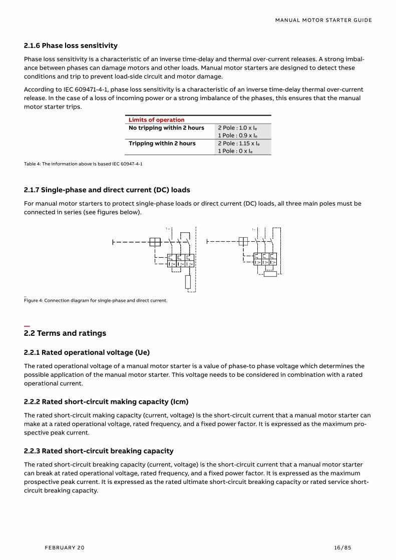
2.1.6 Phase loss sensitivity
Phase loss sensitivity is a characteristic of an inverse time-delay and thermal over-current releases. A strong imbal-
ance between phases can damage motors and other loads. Manual motor starters are designed to detect these
conditions and trip to prevent load-side circuit and motor damage.
According to IEC 609471-4-1, phase loss sensitivity is a characteristic of an inverse time-delay thermal over-current
release. In the case of a loss of incoming power or a strong imbalance of the phases, this ensures that the manual
motor starter trips.
Limits of operation
No tripping within 2 hours 2 Pole : 1.0 x Ie
1 Pole : 0.9 x Ie
Tripping within 2 hours 2 Pole : 1.15 x Ie
1 Pole : 0 x Ie
Table 4: The information above is based IEC 60947-4-1
2.1.7 Single-phase and direct current (DC) loads
For manual motor starters to protect single-phase loads or direct current (DC) loads, all three main poles must be
connected in series (see figures below).
_
Figure 4: Connection diagram for single-phase and direct current.
_ 2.2 Terms and ratings
2.2.1 Rated operational voltage (Ue)
The rated operational voltage of a manual motor starter is a value of phase-to phase voltage which determines the
possible application of the manual motor starter. This voltage needs to be considered in combination with a rated
operational current.
2.2.2 Rated short-circuit making capacity (Icm)
The rated short-circuit making capacity (current, voltage) is the short-circuit current that a manual motor starter can
make at a rated operational voltage, rated frequency, and a fixed power factor. It is expressed as the maximum pro-
spective peak current.
2.2.3 Rated short-circuit breaking capacity
The rated short-circuit breaking capacity (current, voltage) is the short-circuit current that a manual motor starter
can break at rated operational voltage, rated frequency, and a fixed power factor. It is expressed as the maximum
prospective peak current. It is expressed as the rated ultimate short-circuit breaking capacity or rated service short-
circuit breaking capacity.

MANUAL MOTOR STARTER GUIDE
FEBRUARY 20 17/85
2.2.3.1 Rated ultimate short-circuit breaking capacity (Icu) acc. to IEC / EN 60947-2
This is the maximum short-circuit breaking capacity (current, voltage) that manual motor starter can interrupt with-
out being damaged. After the short-circuit interruption, in the event of an overload, the manual motor starter is able
to trip with increased tolerances.
2.2.3.2 Rated service short-circuit breaking capacity (Ics) acc. to IEC / EN 60947-2
This is the short-circuit breaking capacity (current, voltage) that manual motor starters can repeatedly interrupt
without being damaged. After the short-circuit interruption, the manual motor starter is able to carry the rated oper-
ational current and to trip in the case of an overload.
2.2.3.3 What are the difference between the rated ultimate short-circuit breaking capacity (Icu)
and rated service short-circuit breaking capacity (Ics)
The difference between rated ultimate short-circuit breaking capacity Icu and rated service short-circuit breaking ca-
pacity Ics is the test sequence in IEC / EN 60947-2:
− Part 8.3.4 Test sequence II: Rated service short-circuit breaking capacity
− Part 8.3.5 Test sequence III: Rated ultimate short-circuit breaking capacity
The test sequence for Icu is O-t-CO. In this sequence manual motor starter has to switch off a short-circuit (“O”), re-
main off for 3 minutes (“t”) and then it is switched again on this short-circuit in order to switch it off (“CO”). In this
case the overload characteristic curve can change for a longer period of time and the manual motor starter does not
have the full current-carrying capacity.
The test sequence for ICS is O-t-CO-t-CO. In this sequence the manual motor starter hast to switch off the short-cir-
cuit (“O”), have a 3-minute break (“t”), switch on the existing short-circuit and switch it off again (“CO”), have another
3-minute break (“t”), switch on the existing short-circuit again and switch it off again (“CO”). After that, the manual
motor starter must be able to carry the full current and the overload characteristic curve must not change perma-
nently.
2.2.4 Rated short-time withstand current (Icw)
The rated short-time current an item of equipment can withstand is the value of the short-time withstand current,
which the equipment can carry without damage under the test conditions specified in the relevant product standard.
2.2.5 Selectivity categories
The IEC 60947-2 defines two different selectivity categories of low-voltage circuit-breakers:
- Category A = Circuit-breakers not specifically intended for selectivity under short-circuit conditions, which
typically do not have any intentional short‐time delay. The short‐time withstand current is not taken into ac-
count.
- Category B = Circuit-breakers specifically intended for selectivity under short-circuit conditions. ABB manual
motor starters are all selectivity category A. Such breakers must have the possibility for a short‐time delay
and also specify a minimum value short‐time withstand current rating according to standard.
2.2.6 Ambient air temperature compensation
Ambient air temperature compensation is realized by utilizing a bimetal which counteracts the working bimetals of
the inverse time-delay thermal over-current release. This second bimetal is not heated by the motor current but
bends only under the influence of the ambient air temperature. As a result, the influence of the ambient air tempera-
ture on the tripping characteristics of the manual motor starter is automatically compensated for, at an ambient
temperature of 20°C.

MANUAL MOTOR STARTER GUIDE
FEBRUARY 20 18/85
_
Figure 5: Diagram for the Ambient air temperature compensation.
The ambient air temperature compensation is defined in IEC / EN 609471-4-1 within a temperature range from –5 to
+40 °C. The ABB manual motor starters have a temperature compensation from -25°C up to +60°C.
2.2.7 Temperature rise of the manual motor starter
ABB tests the manual motor starters according to the Standard IEC 60947-1 table 2 and 3. This table indicates the
maximum temperature rise of the manual motor starters. Here you will find some example for the temperature rise:
Terminal material Temperature-rise limits a, c
in Kelvin [K]
Bare copper 60
Bare brass 65
Tin plated copper or brass 65
Silver plated or nickel-plated copper or brass 70
Other metals b a The use in service of connected conductors significantly smaller than those listed in Tables 9 and 10 could
result in higher terminals and internal part temperatures and such conductors should not be used without the
manufacturer’s consent since higher temperatures could lead to equipment failure.
b Temperature-rise limits to be based on service experience or life tests but not to exceed 65 K.
c Different values may be prescribed by product standards for different test conditions and for devices of small dimensions, but not exceeding by more than 10 K the values
of this table. _
Table 5: Table 2 from IEC 60947-1 Temperature-rise limits of terminals
Accessible parts Temperature-rise limits a
in Kelvin [K]
Manual operating means:
Metallic
Non-metallic
15
20
Parts intended to be touched but not hand-held:
Metallic
Non-metallic
30
40
Parts which need not be touched during normal operation b:
Exteriors of enclosures adjacent to cable entries:
Metallic
Non-metallic
Exterior of enclosures for resistors
Air issuing from ventilation openings of enclosures for resistors
40
50
200b
200b
A : Different value may be prescribed by product standards for different test conditions and for devices of small dimensions but not exceeding by more than 10 K the values of this table.
B : The equipment shall be protected against contact with combustible materials or accidental contact with personnel. The limit of 200 K may be exceeded if so, stated by the manufac-
turer. Guarding and location to prevent danger is the responsibility of the installer. The manufacturer shall provide appropriate information, in accordance with 5.3. _
Table 6: Table 3 from IEC 60947-1 Temperature-rise limits of accessible parts.
2.2.8 Trip-free mechanism
As required by IEC 60947-1, the manual motor starter features a trip-free mechanism. This means that the manual
motor starter trips even if the handle is locked in the “ON” position or held by hand. According to IEC 60204, a supply
disconnecting device also requires a trip-free mechanism.

MANUAL MOTOR STARTER GUIDE
FEBRUARY 20 19/85
2.2.9 Phase loss sensitivity
According to IEC 609471-4-1, phase loss sensitivity is a characteristic of an inverse time-delay thermal over-current
release. In the case of a loss of incoming power or a strong imbalance of the phases, this ensures that the manual
motor starter trips.
Timely tripping in the event that a two-phase supply is too long prevents an over current in the remaining phases,
which could damage the motor or other loads.
Limits of operation
No tripping within 2 hours 2 Pole : 1.0 x Ie
1 Pole : 0.9 x Ie
Tripping within 2 hours 2 Pole : 1.15 x Ie
1 Pole : 0 x Ie _
Table 7: The information above is based IEC 60947-4-1
During normal operation, the device should be symmetrically loaded on all three poles to prevent early tripping due
to phase loss sensitivity. In order to protect single-phase or direct-current devices, all three main poles have to be
connected in series, see also Chapter: 2.1.7 Single-phase and direct current (DC) loads.
2.2.10 Mechanical and electrical durability
Due to product design characteristics, manual motor starters vary in regard to the number of electrical and mechani-
cal operations which can be sustained over the product life. Below is a comparison between manual motor starters,
contactors and circuit-breakers.
Rating Manual motor starters Contactors
< 100 Amps Circuit-breakers
Mechanical durability Up to 100,000 >10,000,000 25,000
Electrical durability Up to 100,000 >1,000,000 8,000 _
Table 8: Examples of mechanical and electrical durability
Since molded case circuit-breakers are designed to protect circuits and loads rather than control them, the mechani-
cal and electrical durability of these devices is quite low. Contactors which are designed specifically for load control
have very high mechanical and electrical durability. Manual motor starters which are designed to provide both con-
trol and protection are rated higher than general circuit-breaker types.
_ 2.3 Switch and breaker types
Below is a description of the devices for the correct selection, these are applicable for the manual motor starter:
− Motor protection circuit-breaker
− Circuit-breaker
− Load Switch
− Disconnect switch
2.3.1 Motor protection circuit-breaker
Usually this means a device especially for the overload protection of motors. In smaller current ranges the motor pro-
tection switch often serves directly as a manual operation switch. In its original form, it only had a low short-circuit
breaking capacity. Today, the term motor circuit-breaker is also understood to mean a circuit-breaker with motor
protection characteristic

MANUAL MOTOR STARTER GUIDE
FEBRUARY 20 20/85
2.3.2 Circuit-breaker
The circuit-breaker is a mechanical switching device that can switch on, conduct and switch off currents under oper-
ating conditions in the circuit, and can also switch on under specified exceptional conditions, such as a short-circuit,
for a specified period of time, and switch off (IEC 60947-1).
2.3.3 Load switch
The load switch is a mechanical switch that can switch on, conduct and switch off currents under normal conditions
in the circuit, including a specified operational overload, and can also operate under specified exceptional condi-
tions, such as short circuits, for a specified period of time.
A load switch may have a short circuit breaking capacity but does not need to have a short circuit breaking capacity
(IEC 60947-1). Short-circuit currents can be conducted (high short circuit resistance), but not switched off.
2.3.4 Disconnect switch
The disconnect switch is a mechanical switching device that meets the requirements specified for the disconnect
function (IEC 60947-1) in the open position. The disconnection function is to switch off the power supply to the en-
tire system or part of the system, whereby the system or part of the system is disconnected from any electrical
energy source for safety reasons. Important here is the opening distance. The electrical separation from pole to pole
and from input to output must be ensured. This is realized by a visible disconnection point or the device-internal
(mechanical locking device) by appropriate constructive measures.
A device fulfills the isolating characteristic according to IEC 60947-1 if, in the "open" position, it ensures an isolating
distance in which the specified dielectric strength between the open contacts of the main circuit of the switching
device is fulfilled. It must also be equipped with a visible indication with respect to the position of the movable con-
tact pieces. This switch position indicator must be securely connected to the actuator.
A disconnector must be able to open and close a circuit only when either a current of negligible magnitude is turned
off or on, or when there is no appreciable voltage difference between the two terminals of each current path. Devices
fulfilling the “disconnecting function” are marked in the front with the following symbol (acc. to IEC 60974-1):

MANUAL MOTOR STARTER GUIDE
FEBRUARY 20 21/85
_ 2.4 Product offering
ABB provides a comprehensive manual motor starter. Worldwide the manual motor starters device types are divided
into three ranges to simplify selection, coordination, and installation:
- MS116 with a standard performance range up to 32 A
- MS132 / MO132 with high performance ranges up to 32 A
- MS165 / MO165 with high performance ranges up to 80 A
- MS132-T with high performance ranges for transformer protection
MS116
MS132
MS132-K
MS165
MS132-T
MS132-KT
Thermal protection X X X X
Electromagnetic protection X X X X
Phase loss sensitivity X X X X
Switch position ON/OFF ON/OFF/TRIP ON/OFF/TRIP ON/OFF/TRIP
Magnetic trip indication X X X
Lockable handle without accessories X X X
Disconnection function X X X X
Width 45 mm 45 mm 55 mm 45 mm
Rated operational current Ie 0.1 ... 32 A 0.1 ... 32 A 10 ... 80 A 0.1 ... 25 A
Short circuit breaking capacities up to 100 kA up to 100 kA up to 100 kA up to 100 kA
Ambient air temperature (w/o derating) -25 ... +55 °C -25 ... +60 °C -25 ... +60 °C -20 ... +60 °C
MO132
MO165
Thermal protection
Electromagnetic protection X X
Phase loss sensitivity
Switch position ON/OFF/TRIP ON/OFF/TRIP
Magnetic trip indication
Lockable handle without accessories X X
Disconnection function X X
Width 45 mm 55 mm
Rated operational current Ie 0.1 ... 32 A 10 ... 80 A
Short circuit breaking capacities up to 100 kA up to 100 kA
Ambient air temperature (w/o derating) -25 … +60 °C -25 ... +60 °C _
Table 9: Product range of all manual motor starters.

MANUAL MOTOR STARTER GUIDE
FEBRUARY 20 22/85
22.4.1 MS116
MS116 is a compact and economic range for motor protection up to 15 kW (400 V) / 32 A in width of 45 mm. Further
features are the build-in disconnect function, temperature compensation, trip-free mechanism, and a rotary handle
with a clear switch position indicator. The manual motor starter is suitable for three- and single-phase applications.
Auxiliary contacts, signaling contacts, undervoltage releases, shunt trips, power in-feed blocks and locking devices
for protection against unauthorized changes are available as accessories. These are suitable throughout the
MS116/MS132/MS165-range.
2.4.2 MS132
MS132 are manual motor starters with thermal and electromagnetic protection for rated operational currents Ie from
0.10 to 32 A. Just like the MS116, MS132 offers motor protection up to 15 kW (400 V AC) / 32 A and has a width of
45 mm. This type has also a clear and reliable indication of fault in a separate window for the event of short-circuit
tripping. Further features are the built-in disconnect function, temperature compensation, trip-free mechanism, and
a rotary handle with a clear switch position indicator. The manual motor starter is suitable for three- and single-
phase applications. The handle is lockable to protect against unauthorized changes. Auxiliary contacts, signaling
contacts, undervoltage releases, shunt trips, and power in-feed blocks are available as accessories. This manual mo-
tor starter offers a rated service short-circuit breaking capacity Ics = 100 kA at 400 V AC and trip class of 10. Auxiliary
contacts and signaling contacts are available as accessories.
2.4.2.1 MS132-K
MS132-K manual motor starters are similar to MS132, but with Push-In Spring terminals. You can connect rigid or fer-
ruled cables simply by pushing them into the cable holes – there is no need to use any tools. For small cable cross-
sections or for cables without ferrules simply push a screwdriver into the clearly marked holes to open the terminal.
Also, this device has thermal and electromagnetic protection for rated operational currents Ie from 0.10 to 32 A. Just
as MS132, the MS132-K offers motor protection up to 15 kW (400 V AC) and has a width of 45 mm.
2.4.3 MS165
MS165 are manual motor starters with thermal and electromagnetic protection which are designed for significantly
higher currents than the MS116 or MS132, namely from 10 to 80 A. The MS165 offers motor protection up to 45 kW
(400 V AC) with a width of 55 mm. Otherwise, the device has all the features of the MS132.
2.4.4 MS132-T and MS132-KT
MS132-T (screw terminals) and MS132-KT (Push-In Spring terminals) are circuit-breakers for control transformer pro-
tection with thermal and electromagnetic protection for rated operational currents Ie from 0.10 to 25 A. The MS132-T
has the same module width of 45 mm as the MS132 and differs from it by using other releases. Sizes 1 and 2 also cor-
respond to those of the MS132. The short-circuit current setting is fixed to 20 times the operating current to handle
the high inrush current generated by control transformers. MS132-T/MS132-KT should not be used for motor protec-
tion.
2.4.5 MO132 and MO165
MO stands for "magnetic only", accordingly the MO132 and MO165 are manual motor starters with exclusively electro-
magnetic protection. The rated operational currents, the short-circuit breaking capacity, and module width
correspond to the respective devices of the manual motor starter series.
More information about the ABB manual motor starters are easily accessible at ABB’s Download Center(https:/li-
brary.abb.com) All Categories > Products > Low Voltage Products and Systems > Control Product > Manual Motor
Starters

MANUAL MOTOR STARTER GUIDE
FEBRUARY 20 23/85
2.4.6 Accessories and enclosures
Since manual motor starters combine the functions of multiple components, such as circuit-breakers, disconnect
switches, and overload relays, they are offered with many of the same types of accessories. Thus, the manual motor
starters can be extended with auxiliary contacts which can be connected either on the side or - specially to save
space - on the front. Also, undervoltage releases are available, and shunt releases complement the product range.
With the help of separately available adapters can the manual motor starter easily and quickly, build to a compact
starter combinations of motor protection switch and contactor.
Signaling and
status indication
Auxiliary contacts HK1, HKF1
Signal contact alarms SK1
Short-circuit signaling contact CK1
Increasing
functionality
Undervoltage releases UA1
Shunt trips AA1
Current limiters S803W
Reducing
installation time
and saving space
Three-phase busbar PSx
Feeder (in-feed) terminal blocks S1-Mx
Connecting Link BEA
External operation
and enclosures
Handles and shafts, NEMA Types 1, 3R, 12
Shaft alignment accessories
Door-mount kits, NEMA Type 12 DMS132
Enclosures, NEMA Type 12 IB132
Auxiliary and signaling contacts can be combined to provide external status indication for a variety of conditions and
states. The table below shows an overview of the functionality of these contact types.
Contact type
Condition / state of manual motor starter
OFF ON Signaling
contact
Short-
circuit trip
Under-
voltage
release
Shunt trip
HK1, HKF1 Auxiliary con-tacts
Change posi-
tion with the
main contacts
Normally
open O X O O O O
Normally
closed X O X X X X
SK1 Signal contact alarms
Signals trip-
ping by short-
circuit or
overload
Normally
open O O X X X X
Normally
closed X X O O O O
CK1 Short-circuit indicators
Signals trip-
ping by short-
circuit
Normally
open O O O X O O
Normally
closed X X X O X X
O = Open; X = Closed
_
Table 10: Condition / state of manual motor starter.

MANUAL MOTOR STARTER GUIDE
FEBRUARY 20 24/85
2.4.6.1 Building rules for manual motor starters with accessories
Maximum capacity for MS116, MO132 and MS165
_
Figure 6: The maximum capacity for MS116, MO132 and MS165
− One front mounting auxiliary contact HKF1,
− Two accessories mounted on the right:
− one SK1 signal contact alarm and one HK1auxiliary contact
− or two HK1 auxiliary contacts
− One AA1 shunt trip or one UA1 undervoltage release on the left side
Maximum capacity for MS132 or MS165
_
Figure 7: The maximum capacity for MS132 or MS165
− One front mounting auxiliary HKF1 contact,
− Two accessories mounting on the right:
− one SK1 signal contact alarm and one auxiliary HK1contact
− or two auxiliary HK1 contacts
− or one short-circuit CK1 indicator and one SK1 signal contact alarm
− or one CK1 short-circuit indicator and one auxiliary HK1contact
− One AA1 shunt trip or one undervoltage UA1 release on the left side (note: The combination of MS132-K +
UA1 + CK1 is not possible)

MANUAL MOTOR STARTER GUIDE
FEBRUARY 20 25/85
2.4.6.2 Auxiliary contacts HK1 und HKF1
Auxiliary contacts HK1 and HKF1 change position with the main contacts of the manual motor starter. They open and
close a separate circuit depending on the position of the manual motor starter. The interface on the main device is
the breaker. The HK1 is mounted laterally on the right side of manual motor starter and the HKF1 is mounted on the
front side.
_
Figure 8: Auxiliary contacts HK1 und HKF1.
Auxiliary contacts are available in various versions as normally open or normally closed contacts. From the designa-
tion of the auxiliary contact, it can be seen whether it acts as an NC or NO contact. While HK1-11 and HKF1-11 have an
opening and a closing contact, HK1-20 and HKF1-20 have just two NO contacts.
2.4.6.3 Signaling contacts SK1 and CK1
Signaling contacts SK1/SK1-AR and CK1 signal the tripping of the manual motor starter.
With the SK1-AR, a red flag in a window on the front of the device indicates the tripping event, while for SK1 and CK1
the indication on the device itself is done with a protruding orange button.
Another difference between SK1 and SK1-AR is that the contact positions of SK1-AR don't need to be manually reset
after a tripping event, while for SK1 and CK1 this needs to be done by pushing the orange button. The contacts of
SK1-AR are reset to their original position when the manual motor starter is switched back on.
The SK1 signaling contacts signal tripping regardless if it was caused by short-circuit, overload or electrical release
(AA1 or UA1). The CK1 signaling contact only signals tripping in case it was caused by a short-circuit.
All signaling contacts are attached on the right side of the manual motor starter. Unlike SK1-AR, CK1 and SK1 have a
test function, which is activated by engaging the test button in a window on the front of the device with a screw-
driver.
Like auxiliary contacts (HK1/HKF1), signaling contacts are available as normally open or normally closed contacts.
The nomenclature of the type designation corresponds to the logic of the auxiliary contacts.
_
Figure 9: Signaling contacts SK1 and CK1.

MANUAL MOTOR STARTER GUIDE
FEBRUARY 20 26/85
2.4.6.4 Shunt release AA1
The AA1 shunt release has a different direction of action to the UA1. The tripping occurs when a supply current is ap-
plied. Thereby the anchor is attracted and rotates the transfer lever via the slider. In accordance with the basic IEC
60947-1 standard, the manual motor starter must be switched off by the AA1 if the supply voltage of the shunt re-
lease measured during the tripping operation remains between 70% and 110% of the rated control circuit supply
voltage.
2.4.6.5 Under-voltage release UA1
The UA1 under-voltage release releases the manual motor starter or prevents it from being switched on when its volt-
age supply is interrupted. This can be used in emergency switching circuits or can prevent an automatic restart after
voltage interruption.
The basic IEC 60947-1 standard defines the following limits of operation for under-voltage releases:
− When 35% of the rated voltage is applied to the UA1, it must not be possible to switch the manual motor
starter on
− When 85% of the rated voltage is applied to the UA1, it must not be possible to switch the manual motor
starter on
− If the rated voltage goes down, a switched-on manual motor starter must be switched off, over the UA1, at a
voltage between 70% and 35% of the rated voltage

MANUAL MOTOR STARTER GUIDE
FEBRUARY 20 27/85
2.4.6.6 Busbars
Manual motor starters are often built together with contactors for different starter combinations. Three-phase bus-
bars with associated feeder terminals ensure a quick and safe connection for several manual motor starters.
Figure 10: Manual motor starters with busbars
For MS116, MS132, MO132 and MS132-T there are busbars for up to 65 A (PS1-...-65) and busbars for a maximum rated
current of up to 100 A (PS1-...-100) available. Depending on the version, between 2 and 5 manual motor starters with
none, one or two lateral auxiliary contacts can be connected. In addition, there are 3-phase feeder blocks with con-
nection cross-sections of 25 mm² or 35 mm² available.
For MS165 and MO165 ABB offers busbars for up to 125 A (PS2-...-125). As for PS1 busbars between 2 and 5 manual
motor starters with none, one or two lateral auxiliary contacts can be used.

MANUAL MOTOR STARTER GUIDE
FEBRUARY 20 28/85
2.4.6.7 Handles and shafts
By utilizing door coupling rotary operating mechanisms it is possible to operate manual motor starters from outside
of an electrical cabinet. The door coupling mechanism prevents opening of the cabinet door with the manual motor
starter in ON position. The complete mechanism includes handle, shaft, driver, shaft alignment ring and shaft sup-
porter, if required. Most accessories fit for 6 mm shafts with a maximum length of 180 mm. The degree of protection
for MSHD handles is IP64 (NEMA Type 1, 3R, 12).
_
Figure 11: Manual motor starter with Handles and shafts.
_
3. Load types Although the name suggests that their suitable application is limited only to motors, manual motor starters can ad-
ditionally be used for controlling and protecting other types of loads, such as heaters. When combined with an
additional controller, the applications for manual motor starters are even broader. The table below shows the tested
ratings for ABB manual motor starters and AF contactors.
Utilization categories for manual motor starters Utilization categories for contactors < 100 Amps
— AC-1: General use
— AC Motors
— AC-3 / AC-3e: Squirrel-cage motors: starting, switches
off motors during running time
— AC-4: Squirrel-cage motors: starting, plugging, inching
— DC-5: Series-motors, starting, plugging (1), inching (2),
dynamic braking of motors
— AC-1: General use
— AC Resistance Air Heating (100,000 electrical
cycles)
— AC-3 Motors
— Elevator control, AC Motors (500,000 electrical
cycles)
— AC-5a: Electric discharge lamps (ballast)
— AC-5b: Incandescent lamps
— AC-8a: Hermetic refrigerant compressors
— DC-1: General use
— DC Motors
_
Table 11: Load types
MANUAL MOTOR STARTER GUIDE
FEBRUARY 20 29/85
_ 3.1 General use and heaters
The harmonized utilization category AC-1 covers general and resistive type loads. This includes non-inductive or
slightly inductive loads, as well as resistance furnaces and heaters. Additional ratings, such as “Resistance Air Heat-
ing” and “CSA Electrical Heating Control”, which require additional electrical cycling, can be performed to further
validate control devices for use in heating applications. However, the general use of the AC-1 rating is enough for
most heating applications.
ABB manual motor starters are suitable for manual control and protection of heating loads. Magnetic only (MO)
types can be selected when additional overload protection is not required or realized by a separate overload protec-
tion device.

MANUAL MOTOR STARTER GUIDE
FEBRUARY 20 30/85
_ 3.2 Motors
Due to their high inrush peaks, locked rotor currents, and high potential for overheating, motor loads represent one
of the most demanding load types. The figures below show an overview of an across-the-line motor start-up. The
starting current is a characteristic of the motor. The starting time is a function of the load torque, inertia and motor
torque and is influenced by the motor technology. As the starting current ratio (6-13 x Ie) is higher than the rated op-
erational current Ie, an excessively long starting or braking period can cause an overload (temperature rise) in the
motor. This can create electromechanical stresses or damage the motor’s insulation if it is not properly protected.
There are many different manufacturers represented on the market, selling at various prices. Not all motors have the
same performance and quality as motors from ABB, for example. High efficiency enables significant savings in en-
ergy costs during the motors’ normal endurance. In the IEC 60034-30 standard for rotating electrical machines, four
different efficiency classes have been defined.
The classes are called IE1, IE2, IE3 and IE4, where motors belonging to IE4 are the most efficient. See the graph below
for details. A low level of noise is something else that is of interest today, as well as the ability to withstand severe
environments. There are also other parameters that differ. The design of the rotor affects the starting current and
torque and the variation can be quite large between different manufacturers for the same power rating.
_
Figure 12: Diagrams of the different currents at the start-up of a motor.
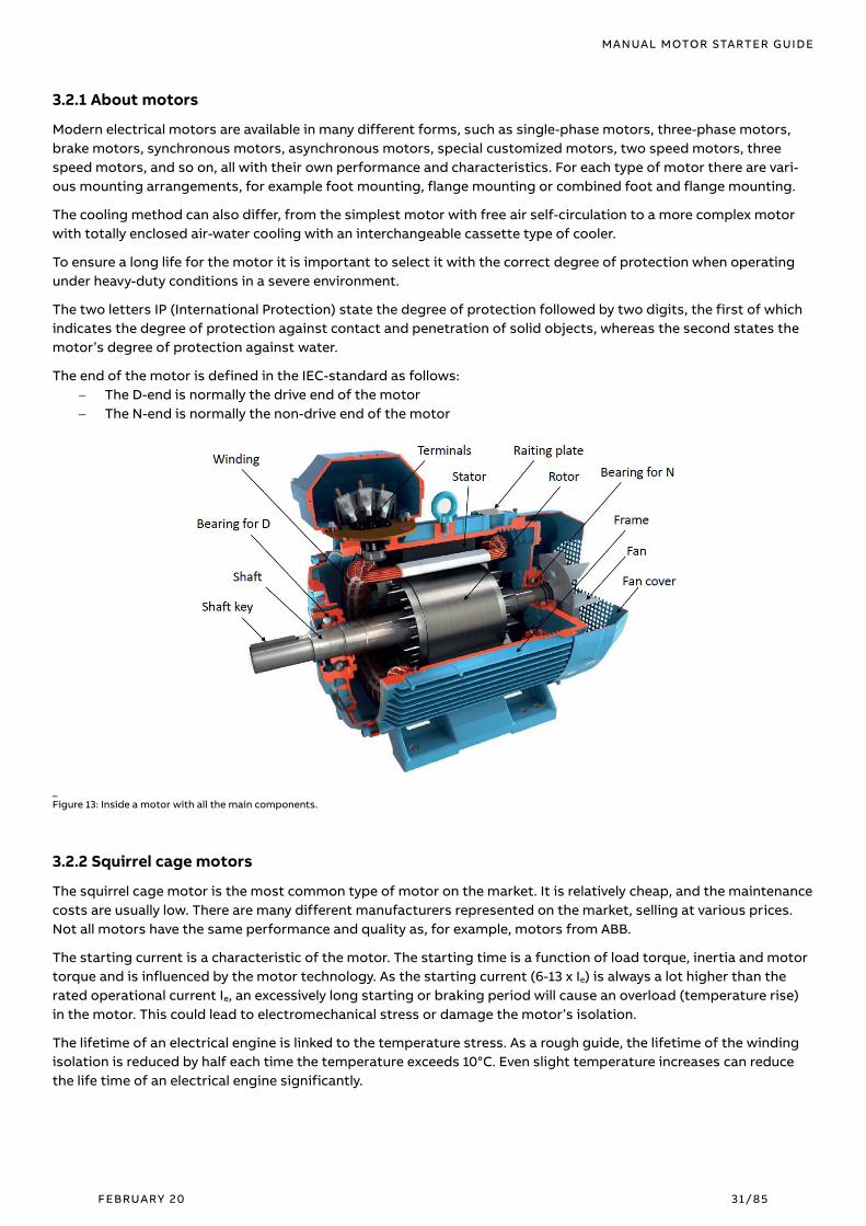
MANUAL MOTOR STARTER GUIDE
FEBRUARY 20 31/85
3.2.1 About motors
Modern electrical motors are available in many different forms, such as single-phase motors, three-phase motors,
brake motors, synchronous motors, asynchronous motors, special customized motors, two speed motors, three
speed motors, and so on, all with their own performance and characteristics. For each type of motor there are vari-
ous mounting arrangements, for example foot mounting, flange mounting or combined foot and flange mounting.
The cooling method can also differ, from the simplest motor with free air self-circulation to a more complex motor
with totally enclosed air-water cooling with an interchangeable cassette type of cooler.
To ensure a long life for the motor it is important to select it with the correct degree of protection when operating
under heavy-duty conditions in a severe environment.
The two letters IP (International Protection) state the degree of protection followed by two digits, the first of which
indicates the degree of protection against contact and penetration of solid objects, whereas the second states the
motor’s degree of protection against water.
The end of the motor is defined in the IEC-standard as follows:
− The D-end is normally the drive end of the motor
− The N-end is normally the non-drive end of the motor
_
Figure 13: Inside a motor with all the main components.
3.2.2 Squirrel cage motors
The squirrel cage motor is the most common type of motor on the market. It is relatively cheap, and the maintenance
costs are usually low. There are many different manufacturers represented on the market, selling at various prices.
Not all motors have the same performance and quality as, for example, motors from ABB.
The starting current is a characteristic of the motor. The starting time is a function of load torque, inertia and motor
torque and is influenced by the motor technology. As the starting current (6-13 x Ie) is always a lot higher than the
rated operational current Ie, an excessively long starting or braking period will cause an overload (temperature rise)
in the motor. This could lead to electromechanical stress or damage the motor’s isolation.
The lifetime of an electrical engine is linked to the temperature stress. As a rough guide, the lifetime of the winding
isolation is reduced by half each time the temperature exceeds 10°C. Even slight temperature increases can reduce
the life time of an electrical engine significantly.

MANUAL MOTOR STARTER GUIDE
FEBRUARY 20 32/85
3.2.3 International motor efficiency standards and regulations
_
Figure 14: International motor efficiency standards and regulations.
Since the validation of IEC 60034-30:2008 and its refined version IEC 60034-30-1:2014, a worldwide energy efficiency
classification system has existed for low voltage three-phase asynchronous motors. These international standards
have been created to enable and increase the level of harmonization in efficiency regulations around the world and to
also cover motors for explosive atmospheres.
IEC 60034-30-1:2014 defines International Efficiency (IE) classes for single speed, three-phase, 50 Hz and 60 Hz in-
duction motors. The efficiency levels defined in IEC 60034-30-1 are based on the test method specified in IEC 60034-
2-1:2014. Both standards are part of an effort to unify motor testing procedures with CSA390-10 and IEEE 112 stand-
ards as well as efficiency and product labeling (IE) requirements to enable motor purchasers worldwide to easily
recognize premium efficiency products.
To promote transparency in the market, IEC 60034-30-1 states that both the efficiency class and efficiency value
must be shown on the motor rating plate and in the product documentation. The documentation must clearly indi-
cate the efficiency testing method used as different methods can produce differing results.
3.2.3.1 Minimum energy performance standards
While the IEC as an international standardization organization sets guidelines for motor testing and efficiency clas-
ses, the organization does not regulate efficiency levels in countries. The biggest drivers for mandatory Minimum
Energy Performance Standard(MEPS) levels for electric motors are global climate change, government targets to
curb CO2 emissions and rising electricity demand, especially in developing countries. The entire value chain, from the
manufacturer to the end user, must be aware of the legislation in order to meet local requirements, to save energy
and reduce the carbon footprint.
Harmonized global standards and the increasing adoption of MEPS around the world are good news for all of us.
However, it is important to remember that harmonization is an ongoing process. Even though MEPS are already in
effect in several regions and countries, they are evolving and differ in terms of scope and requirements. At the same
time, more countries are planning to adopt their own MEPS regulations. A view of existing and coming MEPS regula-
tions in the world can be seen on the world map above.

MANUAL MOTOR STARTER GUIDE
FEBRUARY 20 33/85
3.2.3.2 Efficiency classes of line operated AC motors IEC 60034-30-1
It is important to know which engine types are exempt from the new efficiency regulations. IEC 60034-30-1 defines
four International Efficiency (IE) classes for single speed electric motors that are rated as designed for operation on
sinusoidal voltage:
− IE4 = Super premium efficiency
− IE3 = Premium efficiency
− IE2 = High efficiency
− IE1 = Standard efficiency
_
Figure 15: Overview of the nominal efficiency limits defined in IEC 60034-30-1. Note: you will find a detailed overview of the nominal efficiency limits defined in
IEC 60034-30-1 in the Appendix.
IEC 60034-30-1 covers the power range from 0.12 kW up to 1000 kW. Most of the different technical constructions of
electric motors are covered as long as they are rated for direct on-line operation. The coverage of the standard in-
cludes the recommendation and exclusions below:
IE3/IE4 motor requirements and recommendation IE3/IE4 motor exclusion
− Voltage range for low voltage motors up to 1000 V
− Mains frequency of 50 and 60 Hz
− Number of poles: 2, 4, 6, 8
− Degree of protection: all
− Operating mode: S1 (continuous load), as well as
electric motors designed for other operating
modes, but which can still be operated continu-
ously at rated power - Motors with two switchable
rated voltages (as long as the magnetic flux is the
same at both voltages)
− Temperature range: -20°C to +60°C
− Installation altitude: up to 4,000 m above sea level
− Motors for one speed with 10 or more poles, as
well as motors designed for several speeds
− Motors with mechanical commutators (e.g. DC
motors)
− Motors that are fully integrated into a machine and
cannot be tested independently
− Motors with integrated frequency inverters (com-
pact drives)
− Submersible motors that are especially designed
to be operated completely immersed in liquids
− Explosion-proof motors and brake motors
Note : Additional exclusions are also provided by the European MEPS (EC 640/2009).

MANUAL MOTOR STARTER GUIDE
FEBRUARY 20 34/85
3.2.3.3 What distinguishes an IE3/IE4 motor from less efficient motors?
IE3/IE4 motors can achieve higher efficiency thanks to innovative design and the use of better conducting material.
The higher efficiency design ultimately shows a lower rated motor current for any given kW rating. However, during
the motor’s starting phase, there may be an increase in inrush and starting current. The increased inrush and start-
ing current can in some cases affect the selection of the starter components as well as the short-circuit protection
device.
If a motor is directly connected to the power line, the current drawn (which is mostly reactive) will be very high dur-
ing start-up. The curve in the following graph shows a typical starting RMS current curve for an IE3/IE4 motor in a
direct-on-line connection. In general, the motor draws current in three steps:
• After starting, during the first 10 ms to 15 ms: ‘Ipeak’, an inrush current with a very high peak current. This
high peak current is much higher than for IE1/IE2 motors. This is a result of the higher locked rotor apparent
power and the locked rotor current reaching the higher efficiency class according to IEC 60034-30-1.
• Between the inrush and 0.5 s to 10 s, the important step starts (depending on rated power and inertia), there
is a locked rotor current ‘I lrc’ . This current remains constant as long as the rotor starts revolving. Its’ dura-
tion depends on the motor’s load and design.
• Typically, after 0.5 s to 10 s, the rotor reaches its final speed. The current stabilizes to reach the motor’s rated
current ‘In’ at full load.
_
Figure 15.1: Diagram with the current at the start-up of an IE3/IE4 motor.
The tests and analyzes clearly show that high-efficiency motors IE3/IE4 NE/HE, in general, may draw a higher starting
current than IE3/IE4 N/H motors.
Once the IE3/IE4 motor reaches full speed, the rated motor current is lower compared to IE2 motors for the same
load conditions, because of the higher efficiency (and therefore saving more energy).
Figure 15.2: Diagram showing the different currents for the IE4/IE3 motors.

MANUAL MOTOR STARTER GUIDE
FEBRUARY 20 35/85
3.2.3.4 ABB and efficiency standards
ABB determines efficiency values according to IEC 60034-2-1 using the low uncertainty method with additional load
losses determined by the method of residual loss.
It is good to mention and emphasize that the IEC 60034-2-1 test method, which is known as an indirect method, is
technically equivalent to the test methods in the CSA 390-10 standards and IEEE 112 Method B leading to equivalent
losses and therefore efficiency values.
ABB offers a large range of motors, contactors, and manual motor starters. It has long advocated the need for motor
efficiency, and high-efficiency products have formed the core of its’ portfolio for many years.
ABB supplies high-efficiency motors for additional energy savings when using utilization categories AC-3 and AC-3e
defined according to IEC 60947-4-1. IEC 60947-4-1 Ed.4 introduces a new AC-3e utilization category for AC current
switching, keeping the use and definition of the existing AC-3 utilization category unchanged.
Squirrel-cage motors starting, switching off motors during running, reversing
AC-3 AC-3e
Refers to the asynchronous motors of designs N and H
according to IEC 60034-12:2016.
Refers to asynchronous motors of designs NE and
HE, according to IEC 60034-12, with extended /
higher locked rotor apparent power and current than
designs N and H respectively, to achieve a higher ef-
ficiency class according to IEC 60034-30-1.
The AC-3 category remains with unchanged character-
istics for the complete control and motor protection
product scope defined for motor starting and protec-
tion solutions.
Manual motor starters, 3-pole AF contactors and
B mini-contactors are suitable for AC-3e
applications.
The manual motor starters MS116, MS132, MS165,
and the contactors AF09...AF96, B6/B7 have an
AC-3e rating (same as AC-3 rating):
- listed on their respective technical data pages.
- certified on CB certificates delivered by
third-party laboratories.
- marked on their type label.
For AF116...AF1650 contactors, please consult your
ABB local sales organization
AC-3 making and breaking capacities unchanged New AC-3e making and breaking capacities
3.2.3.5 NEMA® Premium Efficiency motor starting
Since 1926, the National Electrical Manufacturers Association (NEMA) has set standards for motors used in North
America. NEMA regularly updates and publishes MG 1, a book that assists users in the proper selection and applica-
tion of motors and generators. It contains practical information concerning performance, efficiency, safety, testing,
construction, and the manufacture of alternating current (AC) and direct current (DC) motors and generators. The
International Electrotechnical Commission (IEC) defines the standard for electric motors for the rest of the world.
Like NEMA, IEC publishes Standards, the motors guide for the global market.
In 2014 the United States Department of Energy (DOE) established a final rule that covers 3-phase electric motors
from 1-500 hp (0.75 – 370 KW). This final rule became effective on June 1, 2016. It supersedes the Energy Independ-
ence & Security Act (EISA) of 2007. For detailed information please refer to:
https://www.regulations.gov/document?D=EERE-2010-BT-STD-0027-0117
According to this legislation, additional motor types are covered and most exceptions that were possible in both
EPAct 1992 and EISA 2007 legislation have been eliminated. As a consequence, the vast majority of 3-phase industrial
motors are required to meet the efficiencies listed in ANSI/NEMA MG-1, table 12-1x (NEMA Premium® efficiency).

MANUAL MOTOR STARTER GUIDE
FEBRUARY 20 36/85
3.2.4 Rating plate of a motor
The rating plate details on a motor provide the user with information relating to the construction and performance
characteristics of the motor. On the rating plate it is necessary to indicate the IE code and nominal efficiency of the
motor at full load 100 %, 3/4 load 75 % and 1/2 load 50 %, as required by IEC 60034-30-1.
Here is an example of a rating plate:
3.2.5 Voltage
Three-phase single speed motors can normally be connected for two different voltage levels. The three stator wind-
ings are connected in star (Y) or delta (D) configurations. If the rating plate on a squirrel cage motor indicates
voltages for both the star and delta connections, it is possible to use the motor for both 230 V AC, and 400 V AC as
an example.
The winding should be a delta configuration if connected at 230 V AC and if the main voltage is 400 V AC, a star con-
nection is used.
When changing the main voltage, it is important to remember that for the same power rating the rated motor cur-
rent will change depending on the voltage level. The method for connecting the motor to the terminal blocks for star
or delta connection is shown in the picture below.
Basic information:
- Certification label
- Efficiency Code – IE
- Number of phases
- ABB motor type
- Manufacturing date
- Insulation class
- Degree of protection
- Product code
- Motor weight
- IEC Standard
In-/output information:
- Rated operating voltage
- Frequency
- Motor rated power
- Full load speed
- Rated operating current
- Power factor
- Service factor
- Partial load efficiencies
- Rotation speed
- Drive end bearing type and amount of grease
(where applicable) and non-drive end bearing type and
amount of grease (where applicable)
_
Figure 16: Rating plate of a ABB motor
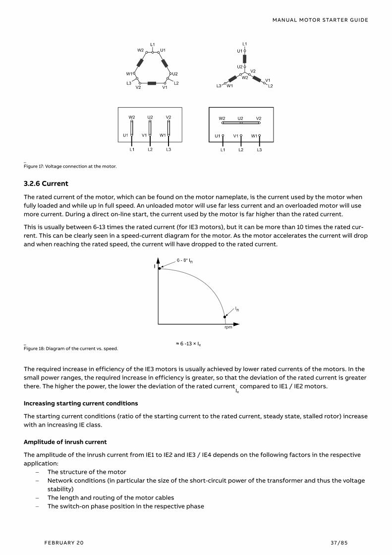
MANUAL MOTOR STARTER GUIDE
FEBRUARY 20 37/85
_
Figure 17: Voltage connection at the motor.
3.2.6 Current
The rated current of the motor, which can be found on the motor nameplate, is the current used by the motor when
fully loaded and while up in full speed. An unloaded motor will use far less current and an overloaded motor will use
more current. During a direct on-line start, the current used by the motor is far higher than the rated current.
This is usually between 6-13 times the rated current (for IE3 motors), but it can be more than 10 times the rated cur-
rent. This can be clearly seen in a speed-current diagram for the motor. As the motor accelerates the current will drop
and when reaching the rated speed, the current will have dropped to the rated current.
_
Figure 18: Diagram of the current vs. speed.
The required increase in efficiency of the IE3 motors is usually achieved by lower rated currents of the motors. In the
small power ranges, the required increase in efficiency is greater, so that the deviation of the rated current is greater
there. The higher the power, the lower the deviation of the rated currents compared to IE1 / IE2 motors.
Increasing starting current conditions
The starting current conditions (ratio of the starting current to the rated current, steady state, stalled rotor) increase
with an increasing IE class.
Amplitude of inrush current
The amplitude of the inrush current from IE1 to IE2 and IE3 / IE4 depends on the following factors in the respective
application:
− The structure of the motor
− Network conditions (in particular the size of the short-circuit power of the transformer and thus the voltage
stability)
− The length and routing of the motor cables
− The switch-on phase position in the respective phase
≈ 6 -13 × Ie
Ie

MANUAL MOTOR STARTER GUIDE
FEBRUARY 20 38/85
3.2.7 Power factor
A motor always consumes active power, which it converts into mechanical action. Reactive power is also required for
the magnetization of the motor, but it does not perform any action. In the diagram below the active and reactive
power is represented by P and Q, which together give the apparent power S.
The ratio between the active power P (kW) and the apparent power S (kVA) is known as the power factor, and is often
designated as the cos ϕ. A normal value is between 0.7 and 0.9. When running, where the lower value is for small or
low loaded motors and the higher for large ones.
_
Figure 19: Diagram indicating P, Q, S and cos ϕ.
3.2.8 Torque
The starting torque for a motor differs significantly depending on the size of the motor. A small motor, e.g., ≤ 30 kW,
normally has a value of between 1.5 and 2.5 times the rated torque, and for a medium size motor, say up to 250 kW, a
typical value is between 2 to 3 times the rated torque. Very large motors tend to have a low starting torque, some-
times even lower than the rated torque. It is not possible to start such a motor fully loaded, not even a direct online
start.
𝑇𝑛 = Rated torque (Nm)
𝑃𝑟 = Rated motor power (kW)
𝑛𝑟 = Rated motor speed (rpm)
_
Figure 20: Diagram of the torque vs. speed.
Different load conditions
All motors are used for starting and running different applications. These applications will result in different load
conditions for the motor. This is a direct braking force on the motor shaft. To be able to accelerate, the motor must
be stronger than the load. The accelerating torque is the difference between the available motor torque and the load
toque. Many starting methods will reduce the torque of the motor and thereby reducing the accelerating torque
which will give a longer starting time. The accelerating torque = the available motor torque – the braking load torque.
The load curve can have different characteristic depending on the application. Some of the common load types can
be seen below.

MANUAL MOTOR STARTER GUIDE
FEBRUARY 20 39/85
_
Figure 21: Diagram of the torque vs. speed for different load conditions.
Many applications are started unloaded, and the load is applied first when the motor has reached the rated speed.
This will reduce the load torque to about 10-50% of the load torque of a loaded start.
Manual motor starters are well suited for both the control and protection of motors, including high-efficiency types.
Since the tests for IEC utilization category AC-3 and UL/CSA “AC Motor” have yet to be fully harmonized, manual mo-
tor starters carry both ratings to ensure international acceptability.
3.2.9 Starting methods
The most common motor starting methods are direct-on-line and star-delta starting.
Connection transients It is important to remember that the term ‘starting current’ refers to a steady-state root-
mean-square (rms) value. This is the value measured when, after a few cycles, the transient phenomena have died
out.
3.2.9.1 Direct-on-line (DOL) starting
The simplest way to start a squirrel cage motor is to connect it directly to the mains supply. In this case, a switch
gear e.g. a contactor is the only starting equipment required. However, the limitation of this method is that it results
in a high starting current, often several times the rated current of the motor. Also the starting torque is very high,
and may result in high stresses on the couplings and the driven application. Even so, it is the preferred method
except when there are special reasons for avoiding it.
3.2.9.2 Star-delta starting
If it is necessary to restrict the starting current of a motor because of supply limitations, the star-delta (Y/Δ) method
can be employed. When a motor wound for 400 V/Δ, for instance, is started with winding Y connected, this method
will reduce the starting current to about 30 % of the current reached with DOL, and the starting torque will be
reduced to about 25 % of its DOL value. However, before using this method, it must be determined whether the
reduced motor torque is sufficient to accelerate the load over the motor’s speed range.
_ 3.3 Hermetic refrigerant compressor motors
A hermetic refrigerant compressor motor is a combination of a compressor and a motor, both of which are enclosed
in the same housing, with no external shaft or shaft seals, with the motor operating in refrigerant. These motors are
commonly used in air-conditioning and refrigeration equipment. Two harmonized utilization categories exist for
these types of loads: AC-8a and AC-8b. AC-8b is an additional test accompanying AC-8a and is referred to as a “recy-
cle rating”, which covers applications where overload releases are automatically reset. Manual motor starters can be
used for manual control and protection of these motors. For control, use AF contactors.

MANUAL MOTOR STARTER GUIDE
FEBRUARY 20 40/85
_ 3.4 Lamps and lighting loads
Two lamp-specific utilization categories exist: AC-5a for electric discharge (florescent) lamps, and AC-5b for incan-
descent lamps, both of which have been fully harmonized. ABB has special lamp starters that are suitable for the
manual control of lamp loads. The table below shows the correlation between these ratings and a variety of commer-
cially available lamps.
Lamp type Ballast AC-5a Tungsten AC-5b
Compact fluorescent lamps X
Florescent lamps with electronic ballast1) X
Halogen electric light bulbs X
Halogen metal vapor lamps X
High-pressure discharge lamps X
Incandescent (filament) light bulbs X
LEDs X
Mercury vapor high-pressure lamps X
Mixed lamps X
Sodium vapor high-pressure lamps X _
Table 12: Lamps and lighting loads.
_ 3.5 Transformers
A transformer is a passive electrical device designed to transform one voltage to another. The load characteristics
are typically different compared to the ones of motors. Therefore, ABB has built a version of manual motor starters
named MS132-(K)T, which is suitable for control and protection of control transformers.
3.5.1 Primary-side protection of transformers
For the primary-side protection of transformers, the inrush current of an open-circuiting transformer must be con-
sidered. Here, due to the supersaturation of the iron core, a high magnetizing current, which may be 15 to 20 times
the rated transformer current occurs, and typically lasts for a period of up to 40 ms.
The power-on spikes will clear within a few milliseconds, but may trigger the short-circuit release, especially on fast,
high-current-limiting circuit-breakers. Slow circuit-breakers are better suited here, especially if the short-circuit re-
lease range can be adjusted and set to a higher value, or a direct release via short delay is possible.
Manual motor starters (only the MS132-T and MS132-KT) for transformer protection are electromechanical protection
devices specially designed to protect control transformers on the primary side. They allow fuse less protection
against overload and short-circuits saving space and cost and ensuring a quick reaction under short-circuit condi-
tions by switching off the transformer within milliseconds. Additionally, the devices allow manual connection and
disconnection of the transformer from the mains.
3.5.2 Secondary-side protection of transformers.
Similarly to motors, transformers are overloadable, depending on the previous continuous power and the coolant
temperature. Transformers are less sensitive to short-term overloads such as motors. Although circuit-breakers offer
too much protection against thermal overload, they are nevertheless well suited for transformer protection.
For the secondary-side protection of transformers, circuit-breakers are used which have a switching capacity equal
to or greater than the transformer short-circuit current. The thermal overload release of the circuit-breaker needs to
be set to the rated transformer current.
Short circuit protection is provided by instantaneous electromagnetic releases. For selectivity tasks for the down-
stream short-circuit protection devices, circuit-breakers with short overcurrent release times need to be provided.
MANUAL MOTOR STARTER GUIDE
FEBRUARY 20 41/85
_ 3.6 Capacitors
AC-6b utilization category according to IEC 60947-4-1
In industrial low voltage installations, capacitors are mainly used for reactive energy correction (raising the power
factor). When these capacitors are energized, overcurrents of high amplitude and high frequencies (3 to 15 kHz) oc-
cur during the transient period (1 to 2 ms).
The amplitude of these current peaks, also known as "inrush current peaks", depends on the following factors:
− The network inductances
− The transformer power and short-circuit voltage
− The type of power factor correction
For more information regarding the control and protection of capacitors, please contact ABB.
_
4. Environmental and application-specific factors Manual motor starters are suitable for use in many climates. They are intended for use in enclosed environments in
which no severe operating conditions (such as dust, caustic vapors or hazardous gases) prevail. When installed in
dusty and damp areas, suitable enclosures must be provided.
_
4.1 Ambient air temperature compensation and derating
According to the standards IEC 60947-2, IEC 60947-4-1, UL 60947-4-1 and CAN/CSA-C22.2 no. 60947-4-1 it is required
to test and validate relevant electrical data (e.g. rated currents, rated frequencies, rated voltages, etc.), typically at
operating ambient air temperatures of -5 °C up to max. 40 °C.
ABB’s manual motor starters exceed this requirement by allowing compensated operation in ambient temperature
ranges for single mounted products in IEC applications of -25 °C up to 60 °C (55 °C for MS116). De-rated values for
the upper limit of the current setting range for ambient temperatures up to 70 °C, for group mounted products and
for UL applications are shown in the application note 2CDC131183M0201. Values between the temperature values can
be linear interpolated.
_ 4.2 Duty cycles and restarting
To avoid issues with nuisance tripping, manual motor starters should not be operated at an arbitrary operating fre-
quency. Applications involving up to 15 starts per hour are acceptable. Higher starting frequencies are acceptable if
the duty ratio is lower and the motor’s making current does not appreciably exceed six times the full-load current.
The diagram below provides guideline values for starts-per-hour as a factor of the duty ratio (ON- vs. OFF-time) and
the time required to start the motor ta.

MANUAL MOTOR STARTER GUIDE
FEBRUARY 20 42/85
_
Figure 22: Diagram of the duty cycles and restarting, Example: for a motor with a duty ratio of 60 percent and a start duration of 1 second, 40 starts per hour
are acceptable.
Example:
The upper diagram represents switched on and off periods of manual motor starter. In the following example we
have 20 sec on- and 20-sec off-period which means we have %50 duty ratio (redpoint in the above diagram).
The graph which can be seen below represents the motor current. In our example, we have 1 sec starting current. Af-
ter 1 sec, our motor goes down to its nominal current. When we apply these assumptions to the below table, we have
50 operations per hour as marked with red dot.
Figure 23: Example of the duty cycles and restarting
After tripping, the bi-metals need to cool down before the manual motor starter can be reset. The rotary handle will
not permit to switch the device to the ON position until this is achieved.
20sec 20sec 20sec 20sec 20sec 20sec t
On/off
I
t
In
1sec 1sec 1sec
(6) x In
Starting Current
On period Off period On period Off period On period Off period

MANUAL MOTOR STARTER GUIDE
FEBRUARY 20 43/85
_ 4.3 Frequencies and direct current (DC)
The magnetic trip values for manual motor starters are valid for frequencies from 50 to 60 Hz. Frequencies other
than 50/60 Hz will have an impact on the instantaneous short-circuit release. In the range from 45 to 66 Hz, the oper-
ating values of the instantaneous short-circuit release are within tolerance. For frequencies above 60 Hz, or for direct
current (DC), the operating value of the instantaneous short-circuit release is increased; for frequencies below 50 Hz,
the operating value of this magnetic release is decreased. Correction factors for these applications are shown below.
_
Figure 24: Diagram of different frequencies and direct current (DC).
Thermal tripping characteristics for manual motor starters are valid for DC and AC with frequencies from 16.66 Hz to
400 Hz (MS116 = 50/60 Hz).
Only the current increase (the steepness of the short-circuit current) is crucial for the opening of the contacts in cur-
rent-limiting circuit-breakers. As soon as the arc is actively conducted from the blowing field into the quenching
chamber and extinguished there, the short-circuit is switched off, regardless of when and if a current zero-crossing
follows.
For symmetrical heating of the thermal overload releases, it is mandatory for manual motor starters to connect all
poles in series. The series connection also leads to a faster shutdown of a short-circuit.
0.8
1
1.2
1.4
1.6
1.8
2
50 100 150 200 250 300 350 400
Co
rre
cti
on
Fa
cto
r
Frequency in Hz
MS132
MS165
16,6
6
DC Value for MS132
DC Value for MS165

MANUAL MOTOR STARTER GUIDE
FEBRUARY 20 44/85
_
5. Selection criteria
_ 5.1 Sizing manual motor starters for motor applications
Manual motor starters should be sized based on the rated current (for UL full-load amps (FLA)) of the motor. The
rated operational current Ie of a manual motor starter represents the maximum current rating of the device. Simi-
larly, to thermal overload relays, these devices are provided with a thermal setting range. Manual motor starters
should be selected so that the motor current rating falls between these ranges. If the thermal setting ranges of two
devices overlap for the intended motor current, select the device with a range that will allow greater flexibility for
adjustment. For magnetic only (MO) manual motor starters, select the device with a rated operational current Ie
equal to, or the next size above, the FLA of the motor.
_ 5.2 Selected Optimized Coordination (SOC)
As a help to select the right ABB product for the application, the “Selected Optimized Coordination” (SOC) web tool
will be very useful.
To guarantee the best performance and the longest lifetime, devices involved in the applications mentioned above
(short-circuit protection devices, contactors, overload relays, soft starters) need to be coordinated.
The coordination between devices cannot be determined directly: tests in power laboratories have to be carried out
to qualify the coordination type at low fault and high fault currents according to IEC or UL standards. ABB coordina-
tion tables are the results of such tests and represent the ABB offerings in terms of motor starting and protection,
selectivity, back-up, and switch-disconnector protection.
In the SOC all available ABB coordination tables are stored and easily accessible. The following chapter will guide you
on the main tasks and user interactions.
The SOC is available on www.abb.com/lowvoltage (in the "Support “menu select "Online Product Selection Tools “,
then select “Coordination Tables”) or at the following permanent link:
https://www.lowvoltage-tools.abb.com/soc/page/selection.aspx
.
_
Figure 25: Screenshot from SOC

MANUAL MOTOR STARTER GUIDE
FEBRUARY 20 45/85
Under the interface “Motor protection” the following filters are available:
− type of protection device
− rated voltage
− short-circuit current
− starter type
− coordination type
− overload relay
− motor rated power
For example: if you are looking for products for motor protection where a manual motor starter is used as a short-
circuit protection device, in a plant where the rated voltage is 400Vac and the IE3 Motor Rated Power is 2.2kW:
_
Figure 26: Screenshot from an example on SOC
SOC shows the right protection device for the selected application depending on the coordination type. Click on >>
to see the complete table
_
Figure 27: Screenshot from a example on SOC

MANUAL MOTOR STARTER GUIDE
FEBRUARY 20 46/85
_
6. Installation and commissioning
_ 6.1 Mounting
Manual motor starters can be mounted as follows:
− Fixed on a 35 mm top hat rail according to DIN EN 60715 (35 x 15 or 35 x 7.5 mm).
− Mounted using a screw fixing on a wall/panel. Manual motor starters can be fastened to the wall/panel using
screws. MS116/MS132 manual motor starters require an additional accessory.
_
Figure 28: Mounting of a manual motor starter.
6.1.1 Mounting position and minimum distances
When mounting the manual motor starters, keep the following clearances to grounded or live parts and insulated
conduit ducts according to IEC 60947-2:
− Single installation: there must be no directly attached contactor and there is a minimum gap of 9 mm to the
left and to the right.
− Group installation: the contactor must be mounted directly or the gap to the left or the right must be less
than 9 mm.
6.1.1.1 Mounting position
Mounting positions 1 until 6 are permitted for manual motor starters.
Mounting: Dismantling:
Pos. 1
Pos. 3
Pos. 2
Pos. 4
Pos. 1 ± 30° Pos. 5 Pos. 6
_
Figure 29: Mounting position of a manual motor starter.

MANUAL MOTOR STARTER GUIDE
FEBRUARY 20 47/85
6.1.1.2 Minimum distance
The following table shows the minimum distance to other units of the same types and also to an electrically conduc-
tive wall (earthed).
MS116 MS132 MS165
Minimum distance to other
units of the same type [mm]
Horizontal 0 0 0
Vertical 150 150 150
Minimum distance to elec-
trically conductive wall
(earthed) [mm]
Horizontal - up to 400 V AC 0 0 0
Horizontal - up to 690 V AC >1.5 >1.5 >1.5
Vertical 75 75 75 _
Table 13: Minimum distance by mounting. _ 6.2 Connection
The manual motor starter can be supplied either from the bottom or from the top (for non-UL applications).
6.2.1 Connection Types
The manual motor starter is available with the following types of connection:
− Screw terminals
− Push-In Spring terminals
Push-In Spring terminals allow conductors to be easily connected directly. The special contact spring allows easy insertion and
guarantees a good contact quality.
6.2.2 Connection cross sections
6.2.2.1 Connection cross sections for screw connection technology
The following tables show the permissible conductor cross-sections for the main connections and auxiliary conduc-
tor connections for sizes MS116, MS132, MO132, MS165 und MO165.
For MS116:
MS116 ≤ 16 A M3.5
0.8 ... 1.2 Nm / 10 ... 12 Ib.in ø 5.5 mm
Pozidriv
No. 2
1/2 x 1 ... 4 mm2 1/2 x 0.75 ... 2.5 mm2
1/2 x AWG 16 ...12 1/2 x 0.75…2.5 mm2 9 mm
MS116 ≥ 16 A M4
2 Nm / 18 Ib.in ø 6.5 mm 1/2 x (1...2.5) (2.5…6) mm2 1/2 x (1...2.5) (2.5…6) mm2
1/2 x AWG 16...8 1/2 x 0.75…6 mm2 10 mm
For MS132 and MO132:
MS132 ≤ 10 A
MO132 ≤ 10 A
M3.5
0.8 ... 1.2 Nm / 10 ... 12 Ib.in ø 5.5 mm
Pozidriv
No. 2
1/2 x 1 ... 4 mm2 1/2 x 0.75 ... 2.5 mm2
1/2 x AWG 16 ...12 1/2 x 0.75…2.5 mm2 9 mm
MS132 ≥ 16 A
MO132 ≥ 16 A
M4
2 Nm / 18 Ib.in ø 6.5 mm 1/2 x (1...2.5) (2.5…6) mm2 1/2 x (1...2.5) (2.5…6) mm2
1/2 x AWG 16...8 1/2 x 0.75…6 mm2 10 mm
For MS165 am MO165:
MS165
MO165
M6
4 Nm / 10 ... 12 Ib.in ø 6.5 mm
Pozidriv
No. 2
1/2 x 1 ... 50 mm2
1/2 x AWG 16...0
1/2 x 1 ... 35 mm2
1/2 x AWG 16...0 1/2 x 1…35 mm2 16 mm
_
Table 14: Connection cross sections for screw connection technology for manual motor starters.

MANUAL MOTOR STARTER GUIDE
FEBRUARY 20 48/85
For accessories
SK1, HK1, HKF1 M3.5
0.8 ... 1.2 Nm / 7 Ib.in ø 5.5 mm
Pozidriv
No. 2
1/2 x 1 ... 1.5 mm2 1/2 x 0.75…1.5 mm2
1/2 x AWG 16…14 1/2 x 0.75…1.5 mm2
8 mm
UA1, AA1 M3.5
0.8 ... 1.2 Nm / 7 Ib.in ø 5.5 mm 1/2 x 1…4 mm2
1/2 x 0.75…2.5 mm2
1/2 x AWG 16…14 1/2 x 0.75…2.5 mm2
S1-Mx-25 M3.5
2.5 Nm / 22 Ib.in ø 5.5 mm
1 x 6…25 mm2
1x AWG 10…4
1 x 6…25 mm2
1x AWG 10…6 10 mm
S1-Mx-35 M8
4.5 Nm / 40 Ib.in
Hexa-
gon 4
1 x 100…35 mm2
1x AWG 8…2
1 x 100…35 mm2
1x AWG 8…2 12 mm
_
Table 15: Connection cross sections for screw connection technology for accessories.
6.2.2.2 Connection cross sections for Push-In Spring terminal technology
The following tables show the permissible conductor cross-sections for main connections and auxiliary conductor
connections of the MS132K manual motor starter:
MS132-K
MS132-K
(Push-in) 1 ... 2.5 mm2
1 … 6 mm²
AWG 10 … 8 1 … 4 mm²
1x 1 … 4 mm²
2x 1 … 2.5 mm 12 mm
MS132 -K (Spring) ø 3 mm
x 0.5 mm 1 ... 2.5 mm2 0.5 ... 4 mm2 1/2 x 0.5 ... 4 mm2 1x 0.5 … 4 mm²
2x 0.5 … 2.5 mm² 12 mm
For accessories
SK1, HK1, HKF1
(Push-in) 1 ... 2.5 mm2
1 … 2.5 mm²
AWG 14 1 ... 2.5 mm2 1 … 1.5 mm² 10 mm
SK1, HK1, HKF1
(Spring)
ø 3 mm
x 0.5 mm 1 ... 2.5 mm2 1 ... 2.5 mm2
AWG 20 … 14 0.5 ... 2.5 mm2 0.5 … 1.5 mm² 10 mm
_
Table 16: Connection cross sections for Push-In Spring terminal technology.
_ 6.3 Motor current setting procedure
Set the current on the scale of the manual motor starter current setting with the help of a screwdriver. Use a screw-
driver on the circuit-breaker scale to set the rated current (setting current) Ie.
_
Figure 30: Motor current setting.
_ 6.4 Overload trip test
The following figure show the procedures for testing the overload tripping of manual motor starter:
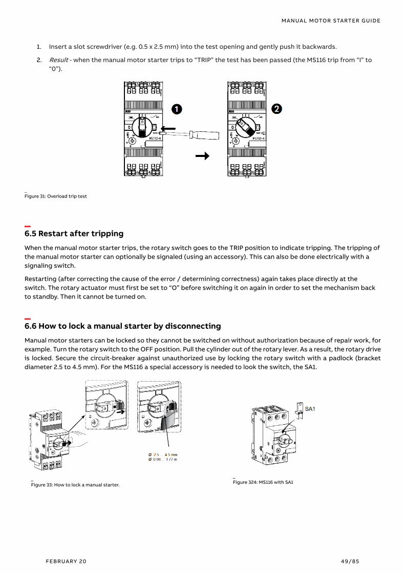
MANUAL MOTOR STARTER GUIDE
FEBRUARY 20 49/85
1. Insert a slot screwdriver (e.g. 0.5 x 2.5 mm) into the test opening and gently push it backwards.
2. Result - when the manual motor starter trips to “TRIP” the test has been passed (the MS116 trip from “I” to
“0”).
_
Figure 31: Overload trip test
_ 6.5 Restart after tripping
When the manual motor starter trips, the rotary switch goes to the TRIP position to indicate tripping. The tripping of
the manual motor starter can optionally be signaled (using an accessory). This can also be done electrically with a
signaling switch.
Restarting (after correcting the cause of the error / determining correctness) again takes place directly at the
switch. The rotary actuator must first be set to “O” before switching it on again in order to set the mechanism back
to standby. Then it cannot be turned on.
_ 6.6 How to lock a manual starter by disconnecting
Manual motor starters can be locked so they cannot be switched on without authorization because of repair work, for
example. Turn the rotary switch to the OFF position. Pull the cylinder out of the rotary lever. As a result, the rotary drive
is locked. Secure the circuit-breaker against unauthorized use by locking the rotary switch with a padlock (bracket
diameter 2.5 to 4.5 mm). For the MS116 a special accessory is needed to look the switch, the SA1.
_
Figure 35: How to lock a manual starter. _
Figure 34: How to lock a manual starter. _
Figure 33: How to lock a manual starter.
_
Figure 324: MS116 with SA1

MANUAL MOTOR STARTER GUIDE
FEBRUARY 20 50/85
_ 6.7 Installation instructions
Installation instructions for manual motor starters can be accessed from the ABB Download Center https://li-
brary.abb.com. All Categories > Products > Low Voltage Products and Systems > Control Product > Manual Motor
Starters.
_ 6.8 2D drawings and 3D models
2D and 3D drawings for manual motor starters and accessories can be accessed from the ABB CAD download portal
(http://abb-control-products.partcommunity.com/portal/portal/abb-control-products).
7. Requirements for North America Electrical machines or electrical plants in the US must be reviewed before being commissioned by an inspector from
the relevant AHJ (Authority Having Jurisdiction). Basis for the decrease is the NEC (National Electrical Code, also
called NFPA 70), the respective application-specific guidelines, such as The NFPA 79, as well as local standards or
specifications.
Operators who do not have their machines or equipment AHJ checked risk losing their insurance protection and
damaging the energy supply. For successful on-site inspections, it is important to carry out the project planning ac-
cording to the required regulations.
_ 7.1 General certification in North America
For electrical products to be legally installed in the United States, the Occupational Safety and Health Administration
(OSHA) lawfully require these devices to be certified through a Nationally Recognized Test Laboratory (NRTL). An
NRTL holds the responsibility for properly certifying manufactures’ products to the appropriate product safety
standards. The OSHA currently recognizes 15 organizations as NRTLs, most notably including:
− Underwriters Laboratories, Inc.
− Canadian Standards Association
− Intertek Testing Services NA, Inc.
Each product certified by an NRTL is given a unique certification mark to indicate conformity, which becomes a clear
sign to inspectors that the product can be legally and safely accepted.
Accreditation in Canada is performed by the Standards Council of Canada (SCC).

MANUAL MOTOR STARTER GUIDE
FEBRUARY 20 51/85
7.1.1 Product certification marks
Each NRTL product mark is unique and differs depending on whether the product has been certified for use in North
America, Canada, or both. This is typically indicated by the inclusion of the letter’s “C” or “US” in the mark. Below are
several examples.
Nationally Recognized Test
Laboratory
Certified for use in the
United States
Certified for use in
Canada
Certified for use in both
the U.S. and Canada
Listed Recognized Listed Recognized Listed Recognized
Underwriters Laboratories,
Inc.
Canadian Standards Asso-
ciation
_
Table 17: Product certification marks
Products are marked to differentiate between whether they are “Listed” devices, indicating that they meet all of the
requirements outlined in the respective product standards, or “Recognized” devices, which meet only some of the
requirements of their standard. Recognized components are subject to additional “Conditions of Acceptability”
which can be somewhat limiting regarding their use in electrical installations.
ABB manual motor starters are Listed products bearing a cULus mark.
7.1.2 Joint U.S.-Canadian approvals
The Memorandum of Understanding (MOU), signed between UL and CSA in 2003, affords manufacturers the ability
to certify products for both the U.S. and Canada through a single organization. This reduces the time to bring prod-
ucts to the market and allows the most state-of-the-art products to start benefiting customers more quickly. The
MOU covers the mutual acceptance of components certified by either organization for use in electrical end-product
equipment (e.g., Industrial Control Panels).
For more information regarding the MOU, please follow the links shown below.
(http://ul.com/newsroom/pressreleases/expansion-of-ul-csa/).
(http://www.csagroup.org/ca/en/services/testing-and-certification/agreement-on-acceptance-of-components).
7.1.3 Relevant North American standards
The question is which standard needs to be used in which application. When should the UL 508A, NFPA 79 or both be
used? In most cases the requirements and interfaces should be clearly regulated by both standards. The overlap re-
quirement is generally the norm. Below is an overview of the North American standards referenced in this document.

MANUAL MOTOR STARTER GUIDE
FEBRUARY 20 52/85
General installation standards
— Govern the installation of electrical components
and conductors in each country
— Scopes include all electrical installations beyond
the point of the utility service drop
— Applicable for residential, commercial, and indus-
trial structures
— Often adopted into law by local governments
NFPA® 70 National Electrical Code® (NEC)
United States
CSA C22.1 Canadian Electrical Code (CEC)
Canada
NOM-001-SEDE-2012 Instalaciones Eléctricas (utilización)
Mexico
Application-specific standards
— Govern specific applications (e.g., industrial control
panels)
— Can allow for greater flexibility when designing and
building electrical equipment
NFPA® 79 – Industrial Machinery
UL 508A – Industrial Control Panels
CSA C22.2 No.14 – Industrial Control Equipment
Product standards
— Govern the products themselves
— Quantify the necessary product construction,
marking and tests required for certification
UL 60947-4-1 – Electromechanical Contactors and Motor-Starters
UL 508 – Industrial Control Equipment
UL 508A – Industrial Control Panels
UL 508C – Power Conversion Equipment
UL 489 – Molded-Case Circuit-breakers, Molded-Case Switches, and C.B. Enclo-
sures
UL 98 – Enclosed and Dead-Front Switches
UL 1077 – Supplementary Protectors for Use in Electrical Equipment
UL 248-1 – Low-Voltage Fuses
CSA C22.2 No.60947-4-1 – Electromechanical Contactors and Motor-Starters
CSA C22.2 No.14 – Industrial Control Equipment
CSA C22.2 No.274 – Adjustable Speed Drives
CSA C22.2 No.5 – Overcurrent Protection
CSA C22.2 No.4 – Enclosed and Dead-Front Switches
CSA C22.2 No.235 – Supplementary Protectors
CSA C22.2 No.248 – Low-Voltage Fuses
_
Table 18: Relevant North American standards.
7.1.4 Global harmonization efforts
As globalization continues to impact consumers more and more each year, it is becoming increasingly important for
customers to understand the rules and regulations of multiple world regions. To limit the scope of knowledge re-
quired to achieve this without sacrificing safety, standards development organizations, including Underwriters
Laboratories (UL), the Canadian Standards Association (CSA), and the International Electrotechnical Commission
(IEC) are working together. They are combining best practices, eliminating antiquated verbiage, and producing har-
monized global standards.
Most notably for the purpose of this document, these organizations have adopted the IEC 60947-4-1 standard to har-
monize the UL 60947-4-1 and CSA C22.2 No. 60947-4-1 standards for Electromechanical Contactors and Motor-
Starters, which now govern the certification of manual motor starters, replacing UL 508 and CSA C22.2 No.14.
7.1.5 Categorizing manual motor starters
Products certified through UL are categorized according to their intended use. This categorization is part of a hierar-
chical structure of 4-digit codes, referred to as Category Codes (7.1.5 Categorizing manual motor starters). In
addition to providing a means for categorization, CCNs also provide installers with clear directions regarding how to
properly apply the devices. This is important to consider, as although two products may appear physically similar,
their suitable uses may differ drastically. To help avoid issues in regard to proper application, the Online Certification
Directory available on the UL’s website provides customers with a means of searching for certified components
(http://ul.com/database).

MANUAL MOTOR STARTER GUIDE
FEBRUARY 20 53/85
Manual motor starters belong to two separate CCNs:
Manual Motor Controllers
NLRV Dual categories
Combination Motor Controllers
NKJH
NLRV Listed Manual Motor Controllers certified according to
UL 60947-4-1 (UL 508) for use in the United States
Listed Combination Motor Controllers certified according to
UL 60947-4-1 (UL 508) for use in the United States NKJH
NLRV7 Listed Manual Motor Controllers certified according to
CSA C22.2 No. 60947-4-1 (CSA 22.2 No.14) for use in Canada
Listed Combination Motor Controllers certified according to
CSA C22.2 No. 60947-4-1 (CSA 22.2 No.14) for use in Canada NKJH7
_
Table 19: Categorizing manual motor starters
Naturally, any attempt to categorize the vast array of products and technologies available for electrical applications
can create drawbacks. Most notably, CCNs are intentionally broad, and are often unable to differentiate between sim-
ilar products technically. For this reason, manual motor starters tested and classified under CCN Manual Motor
Controllers (NLRV) occupy the same category as other manual controllers, such as non-fusible disconnect switches,
meaning that the inclusion of protective releases, such as thermal and magnetic trip mechanisms, is often under-
stated our completely overlooked.
To credit their ability to protect circuits in addition to loads, manual motor starters can be tested and classified un-
der an additional product CCN – Combination Motor Controllers (NKJH). This also means that the suitable
applications for manual motor starters are split between the two categories. he simplest explanation of the division
of applications can be viewed as:
Applications requiring an upstream branch circuit
protective device (fuses or 489/No.5 circuit-breaker)
Applications requiring no additional branch
circuit protection
Manual Motor Controllers (NLRV) Combination Motor Controllers (NKJH)
— Single motor disconnects
— Group installations
— Tap conductor protection in group installa-
tions
— Manual self-protected Type E
— Type F
— Protection of ABB Micro drives
_
Table 20: Applications requiring
7.1.5.1 Tap conductor definition from section 240.2 of the National Electrical Code (NEC), 2014 edition
“A conductor, other than a service conductor, that has overcurrent protection ahead of its point of supply that ex-
ceeds the value permitted for similar conductors that are protected as described elsewhere in 240.4.”
A Tap conductor is defined in the NEC 2014 edition electrical code tap rules. The NEC article dealing with overcurrent
protection of feeder taps is article 240.21(B). These rules are often referred to as the NEC “tap rules”.
There are five tap rules related to feeder circuit taps:
− Taps not over 3 m (10 ft.) long
− Taps not over 7.5 m (25 ft.) long
− Taps supplying a transformer [primary plus secondary not over 7.5 m (25 ft.) long]
− Taps over 7.5 m (25 ft.) long
− Outside taps of unlimited length
7.1.6 Selecting the right Short Circuit Current Ratings (SCCR) level for your UL application
With so many different applications and ratings available for manual motor starters, it can sometimes be difficult to
know which SCCR to select. Below is some general advice to assist in the selection. Additionally, an “SCCR reference”
is shown next to each application diagram in the previous section. This reference correlates to a UL/CSA maximum
short-circuit current rating table column header. These tables can be found in our Main Catalog for Motor Protection
and Control which can be accessed in the Download Center (https://library.abb.com) All Categories > Prod-
ucts > Low Voltage Products and Systems > Control Product > Manual Motor Starters.

MANUAL MOTOR STARTER GUIDE
FEBRUARY 20 54/85
_
Figure 35: Screenshot from the catalog of the UL/CSA maximum short-circuit current rating table.
If the secondary winding style of the upstream facility transformer is known to be wye, or for delta networks
347 V AC and below, consider first the application of manual motor starters as combination motor controllers. For
manual control, select from the “Type E” SCCR. For remote control, select from “Type F”, and ensure that any mini-
mum component size requirements are respected.
For delta networks above 347 V AC, consider the addition of an upstream fuse block and fuses. The manual motor
starter can serve as the main branch disconnect when marked “Suitable as Motor Disconnect” and positioned on the
load-side of the branch circuit protective device. The “Motor disconnect” SCCR should referenced. These ratings ap-
ply whether the upstream BCPD contains fuses or a circuit-breaker unless otherwise noted.
For panels designed to control multiple branch circuits, consider the possibility of a group installation. Most indus-
trial control panels are supplied by a circuit-breaker or set of fuses that could be sized based on the requirements for
group installation. In the U.S., when using manual motor starters in group installations for manual control, the “Tap
Conductor Protection” SCCR should be referenced. For Canada, or for the U.S. when also combining AF contactors for
remote control, select from the “Group installation” SCCR. A 3-phase accessory busbar is available to provide a com-
pact solution for group installation.
If the upstream protective device is too large to protect the group, or if any of the other requirements for group in-
stallation cannot be met, manual motor starters should be employed as non-combination starters. They can provide
manual control themselves or provide overload protection as part of a magnetic or solid-state starter assembly.
Close coupling adaptors are available for AF contactors and PSR softstarters to reduce installation time and panel
space. In these applications, the “Motor disconnect” SCCR is referenced. If an additional controller is used (e.g., con-
tactor), use the component-level short-circuit current ratings for these devices.
_ 7.2 North American voltage supply networks and load types
Electrical networks in North America supply power to residential, commercial, and industrial structures. Depending
on the amount of power required for a given installation, various voltage configurations can be utilized.
7.2.1 North American voltages
North American commercial installations are typically supplied using either 120/240 V AC split (dual) or
208Y/120 V AC, 3-phase wye networks. Industrial installations within the U.S. commonly use 480Y/277 V AC, 3-phase
wye networks. For Canada, the network voltages are increased to 600Y/347 V AC. However, 3-phase delta networks,
which do not offer a line-to-neutral voltage, are also common, most often supplying either 240, 480 or 600 V AC.
Application Network configuration
(excluding ground wire)
Nominal supply voltage
(line-to-line)
Nominal supply voltage
(line-to-neutral)
Commercial 2-phase, 3-wire 240 V AC 2-phase (split/dual) 120 V AC 1-phase
3-phase, 4-wire (wye) 208 V AC 3-phase 120 V AC 1-phase
Industrial and large commercial
in the United States
3-phase, 3-wire (delta) 240 V AC 3-phase --
3-phase, 4-wire (wye) 480 V AC 3-phase 277 V AC 1-phase
3-phase, 3-wire (delta) 480 V AC 3-phase --
Industrial and large commercial
in Canada
3-phase, 4-wire (wye) 600 V AC 3-phase 347 V AC 1-phase
3-phase, 3-wire (delta) 600 V AC 3-phase --

MANUAL MOTOR STARTER GUIDE
FEBRUARY 20 55/85
_
Table 21: North American voltages
Manual motor starters are commonly applied in both industrial and commercial applications. To meet the require-
ments for North America, they are suitable for use on 1- and 3-phase networks with line-to-line voltages up to
600 V AC.
7.2.2 Three-phase network configurations
North American 3-phase supply networks differ based on the secondary winding of the upstream transformer. The
two most common secondary winding styles are wye, which includes three power legs and a neutral, and delta, which
includes only three power legs without a neutral connection. These networks can be either grounded or ungrounded.
Solidly grounded wye and ungrounded delta networks are most common in North America.
Most common
Delta
(ungrounded)
Wye Delta
(corner-grounded)
Delta
(center-grounded)
Solidly grounded networks _
Figure 366: Three-phase network configurations.
7.2.3 Straight vs. slash voltage ratings
Short-circuit protective devices with straight voltage ratings (e.g., 480 V AC) can be applied in any circuit, grounded
or ungrounded, where the line-to-line voltage does not exceed the maximum rating specified.
Short-circuit protective devices with slash voltage ratings (e.g., 480Y/277 V AC) can be applied only in solidly
grounded networks where the voltage from line-to-ground does not exceed the lower of the two ratings
(e.g., 277 V AC), and the voltage from line-to-line does not exceed the higher of the two ratings (e.g., 480 V AC). The
lower rating represents the device’s interrupting capability per pole.
Depending on the how they are applied, manual motor starters carry either straight (Δ) or slash (/) voltage ratings.
Rating type Maximum
voltage
Manual Motor Controller 600 Δ
Manual Motor Controller, Suitable as Motor Disconnect 600 Δ
Manual Motor Controller, Suitable for use in Group Installations 600 Δ
Manual Motor Controller, Suitable for Tap Conductor Protection in Group Installations1) 600Y/347 V
Manual self-protected Combination Motor Controller (Type E for UL) 600Y/347 V
Combination Motor Controller (Type F for UL) 600Y/347 V
Protection of ABB Micro drives 480Y/277 V 1) MS132/MO132 and MS165/MO165 only
Table 22: Straight vs. slash voltage ratings

MANUAL MOTOR STARTER GUIDE
FEBRUARY 20 56/85
7.2.4 Short-circuit current ratings
Short-circuit current ratings (SCCR) are tested values for motor control and protection devices to ensure safe reac-
tion during short-circuits and ground faults. Since even low-level faults can produce incredible amounts of energy,
unprotected equipment can easily cause damage to the installation and endanger personnel within close proximity.
Short-circuit current ratings have been mandatory for industrial control panels since 2006.
A complete list of ABBs tested SCCRs can be accessed online through our SOC selection tool
(https://www.lowvoltage-tools.abb.com/soc/page/selection.aspx).
7.2.5 Components requiring short-circuit current ratings
All power circuit components for industrial control panels are required to have marked short-circuit current ratings
expressed in kiloamperes and voltage. This includes devices such as:
− Disconnect switches
− Branch circuit protective devices
− Branch circuit fuse holders
− Load controllers
− Motor overload relays
− Terminal blocks
− Busbars
ABB manual motor starters are tested for short-circuit current ratings in a wide variety of applications. SCCR values
for manual motor starters may differ depending on how they are applied. See Chapter 7.1.6 Selecting the right Short
Circuit Current Ratings (SCCR) level for your UL application for more guidance regarding the selection.
7.2.6 Standard (low) fault ratings - Mandatory
For electrical products to be certified as suitable for use in motor applications, they must be tested to a minimum
standard value based on the size and type of the device. These are referred to as standard fault or low fault ratings.
The table below shows the standard values for motor controllers according to UL 60947-4-1 and CSA C22.2 60947-4-1.
Standard fault test cur-
rent, rms symmetrical
Maximum hp
600 V AC or less Maximum kW
Maximum Amps
600 V AC – 1500 V AC
1 kA 0 – 1 hp 0 – 0.746 kW --
5 kA Over 1 – 50 hp Over 0.746 – 38 kW 0 – 50 A
10 kA Over 50 – 200 hp Over 38 – 149 kW Over 50 – 200 A
18 kA Over 200 – 400 hp Over 149 – 298 kW Over 200 – 400 A
30 kA Over 400 – 600 hp Over 298 – 441 kW Over 400 – 600 A
42 kA Over 600 – 900 hp Over 441 – 671 kW Over 600 – 850 A
85 kA Over 900 – 1600 hp Over 671 – 1193 kW Over 850 – 1500 A
100 kA Over 1600 hp Over 1193 kW Over 1500 A _
Table 23: Standard (low) fault ratings – mandatory. Note: for a manual motor controller intended for use as a means of disconnection, the minimum short-
circuit current rating is 5kA. The information above is based on UL 60947-4-1 Table 9.3.4.2.1DV.1.1.1 and is intended for reference only.
The standard fault value is also the assumed rating for unmarked components.
IEC refers to standard fault current as a prospective current “r”.
7.2.7 High fault ratings - Optional
The standard fault values shown in the previous chapter are the minimum requirements for all motor control compo-
nents. Since the available fault current for a given installation can vary drastically, standard fault ratings alone are
often too low for many applications. For this reason, manufactures, including ABB, often choose to test their devices

MANUAL MOTOR STARTER GUIDE
FEBRUARY 20 57/85
beyond the minimum requirements. Any short-circuit testing above the minimum standard fault level and up to a
maximum of 200 kA is referred to as a high fault rating.
There are two methods for testing high fault SCCRs. The first method, referred to as component-level testing, is per-
formed in an enclosure, but with the upstream short-circuit protective device mounted separately in the open air.
This is common for devices intended to be supplied separately from the short-circuit protection. The second
method, which applies to combination starters, involves testing with all components in a single enclosure. This is
referred to as combination motor controller (CMC) testing. CMC testing is common for devices supplied as a com-
plete assembly (e.g., enclosed starters).
IEC refers to high fault current as rated conditional current Iq
7.2.8 Defined acceptance criteria
Failure of components under fault conditions can lead to safety concerns for personnel working in close proximity to
electrical equipment. To outline what constitutes a pass, the harmonized UL 60947-4-1 and CSA C22.2 No.60947-4-1
standards define acceptance criteria for these components. Several criteria exist for all devices:
− The short-circuit protective device successfully interrupts the fault
− The enclosure door has not blown open, and it remains possible to open it manually
− No damage to, or separation between, the conductors and the terminals
− No damage to the insulating bases of live parts, and no access to current carrying parts
For Combination Motor Controllers, the included circuit-breaker, switch, or manual motor starter should be capable
of being manually operated, and should not be damaged, exposing conductive parts.
In addition to the above criteria, a distinction is made between two types of coordination: Type 1 and Type 2. This
pertains to the suitability of components for continued service following a fault.
7.2.8.1 Type 1 coordination
Type 1 coordination allows some components, such as the controller and overload protection device, to sustain dam-
age such that they become inoperable following a short-circuit fault. This coordination type requires that these
components are replaced before re-commissioning.
7.2.8.2 Type 2 coordination
Type 2 coordination requires that no damage to the overload protection and other components occurs, with the ex-
ception that the contacts of the contactor or starter are allowed to be welded. This welding must be easily separated
by manual effort (e.g. with a screwdriver). Both the overload tripping performance and controller switching capabili-
ties are verified following the short-circuit test.
7.2.9 Calculating the available fault current for a facility
What rating do I need? The necessary short-circuit current rating for any device is determined based on the available
fault current at its point of installation.
Most industrial and commercial buildings are supplied by one or more transformers proving incoming power to the
facility. Using rated information from these transformers, it is possible calculate the available fault current for any
installation within the building. UL 508A provides the following formulas for determining available fault current in
circuits containing transformers with isolated secondary windings.
Available fault current beyond single-phase transformers Available fault current beyond 3-phase transformers
𝐼𝑠𝑐 =
(𝑘𝑉𝐴 × 1000
𝑉𝑠𝑒𝑐𝑜𝑛𝑑𝑎𝑟𝑦)
𝑍%
𝐼𝑠𝑐 =
(𝑘𝑉𝐴 × 1000
𝑉𝑠𝑒𝑐𝑜𝑛𝑑𝑎𝑟𝑦 × √3)
𝑍%
√3 ≈ 1.732

MANUAL MOTOR STARTER GUIDE
FEBRUARY 20 58/85
The available fault current directly at a transformer’s secondary terminals 𝐼𝑠𝑐 can be calculated from the transformer
rating ( 𝑘𝑉𝐴), the secondary voltage line-to-line 𝑉𝑠𝑒𝑐𝑜𝑛𝑑𝑎𝑟𝑦 and the transformer impedance 𝑍%. For transformers with
an unmarked impedance, this can be assumed to be 2.1 %.
Let’s consider a facility supplied by a 3-phase, 3000 kVA transformer with an isolated secondary winding producing
480 V AC line-to-line, and with a marked impedance of 5.75%. Using the formula above, we can calculate the maxi-
mum available fault current for this facility to be just under 63 kA (62.755 A).
Since this calculation does not account for any additional impedance from the wires, and also assumes infinite utility
source power, the calculated value can be assumed to be “worst-case” for any installation supplied from this power
source.

MANUAL MOTOR STARTER GUIDE
FEBRUARY 20 59/85
7.2.10 Additional current limiting devices
In addition to transformers, other devices, such as some types of fuses and circuit-breakers, also serve to limit the
available fault current within a facility. The published let-through energy I2t and peak let-through Ip can be used to
determine the load-side available fault current. The higher of these two ratings is the available fault current beyond
the device.
Using our example above, we know that our facility has a maximum available fault current of 63 kA. Let’s assume that
for a 63 kA fault at 480 V AC, a current-limiting circuit-breaker as has an I2t of 30 kA²s, and an Ip of 27 kA. The available
fault current downstream from this circuit-breaker is 30 kA. In this example, the required SCCR for all components
installed beyond this circuit-breaker must be equal to, or greater than, 30 kA at 480 V AC.
_ 7.3 Defining branch circuits
Electrical distribution within a facility requires the coordination of many circuits to loads. Beyond the point of the
service entrance, all circuits leading away are considered feeders or feeder taps, until just ahead of a load. The circuit
between the load-side terminals of the final overcurrent protective device and the load itself is called the branch cir-
cuit. This also means that the branch circuit protective device is part of the feeder circuit, not the branch. The figure
below shows an example of this.
Feeder vs. branch circuits
_
Figure 37: Defining branch circuits.
Manual motor starters are suitable for branch circuit protection when tested as Type E or F combination motor con-
trollers. However, these devices cannot be used for providing protection of feeder circuits. Feeder circuit protection
is typically provided using either fuses, UL 489 / CSA C22.2 No.5 molded case or UL 1066 / CSA C22.2 No.31 power
circuit-breakers.
The term “branch circuit’ applies regardless of the type of load. Common load types for industrial and commercial
applications include motors, heaters, and lamps. The requirements for motor branch circuits are more intense than
other load types, so the following section reviews these requirements in detail.

MANUAL MOTOR STARTER GUIDE
FEBRUARY 20 60/85
_
7.4 Tap conductor definition from section 240.2 of the
National Electrical Code (NEC) “A conductor, other than a service conductor, that has overcurrent protection ahead of its point of supply that ex-
ceeds the value permitted for similar conductors that are protected as described elsewhere in 240.4.”
A Tap conductor is defined in the NEC electrical code tap rules. The NEC article dealing with overcurrent protection of
feeder taps is article 240.21(B). These rules are often referred to as the NEC “tap rules”.
There are five basic tap rules related to feeder circuit taps:
− Taps not over 3 m (10 ft.) long
− Taps not over 7.5 m (25 ft.) long
− Taps supplying a transformer [primary plus secondary not over 7.5 m (25 ft.) long]
− Taps over 7.5 m (25 ft.) long
− Outside taps of unlimited length
The NEC has some very specific requirements for each of these tap rules which are shown on some examples in the
following chapters below.
7.4.1 (1) Taps not over 3 m (10 ft.) long. If the length of the tap conductors does not exceed 3 m (10 ft.) and the tap
conductors comply with all the following:
− The ampacity of the tap conductors is
a. Not less than the combined calculated loads on the circuits supplied by the tap conductors, and
b. Not less than the rating of the equipment containing an overcurrent device(s) supplied by the tap conduc-
tors or not less than the rating of the overcurrent protective device at the termination of the tap conductors.
Exception to b: Where listed equipment, such as a surge protective device(s) [SPD(s)], is provided with spe-
cific instructions on minimum conductor sizing, the ampacity of the tap conductors supplying that
equipment shall be permitted to be determined based on the manufacturer’s instructions.
− The tap conductors do not extend beyond the switchboard, switchgear, panelboard, disconnecting means,
or control devices they supply.
− Except at the point of connection to the feeder, the tap conductors are enclosed in a raceway, which extends
from the tap to the enclosure of an enclosed switchboard, switchgear, a panelboard, or control devices, or to
the back of an open switchboard.
− For field installations, if the tap conductors leave the enclosure or vault in which the tap is made, the ampac-
ity of the tap conductors is not less than one-tenth of the rating of the overcurrent device protecting the
feeder conductors.
7.4.2 (2) Taps not over 7.5 m (25 ft.) long. Where the length of the tap conductors does not exceed 7.5 m (25 ft.) and
the tap conductors comply with all the following:
− The ampacity of the tap conductors is not less than one-third of the rating of the overcurrent device protect-
ing the feeder conductors.
− The tap conductors terminate in a single circuit breaker or a single set of fuses that limit the load to the am-
pacity of the tap conductors. This device shall be permitted to supply any number of additional overcurrent
devices on its load side.
− − The tap conductors are protected from physical damage by being enclosed in an approved raceway or by
other approved means.
A highly simplified paraphrasing of the NEW tap rules has two main points:

MANUAL MOTOR STARTER GUIDE
FEBRUARY 20 61/85
− 1. A conductor rated a minimum of 10% of the ampacity of a feeder conductor may be tapped from the
feeder provided its length is not greater than 10 feet and it terminates in an appropriately sized overcurrent
protective device.
− 2. A conductor rated a minimum of 33% of the ampacity of a feeder conductor may be tapped from the
feeder provided its length is not greater than 25 feet and it terminates in an appropriately sized overcurrent
protective device.
7.4.3 Addressing the need for tap conductors
Some panel builders may use power distribution blocks to distribute electrical power to multiple loads, but many
power distribution blocks have a low short-circuit current rating (SCCR). Since their usage will lower the SCCR of
the entire assembly, a better alternative solution may be to distribute branch circuits directly from the circuit
breaker’s terminals. In order to do this, the circuit breaker terminal must have provisions to accept more than
one cable per phase.
Terminals for larger circuit breakers often can accept two or more conductors and some circuit breaker manufac-
turers may have multi-conductor lugs available as an accessory for smaller circuit breakers. Normally, multi-
conductor lugs on larger-frame circuit breakers are used to supply a single large load from a single circuit
breaker, but this need not be the only application for these lugs. These multi-conductor lugs may also be used to
split or distribute the cables to feed more than one smaller load from the circuit breaker by using the NEC tap
rules.
7.4.4 Short-circuit current ratings
Power distribution blocks may serve the purpose of distributing electrical circuits; their function is to provide a
means to tap smaller conductors from a larger conductor, provided the tapping rules are followed. Conductors
equal to the full ampacity of the circuit breaker must be extended to the power distribution block, and then
properly sized taps may extend from the power distribution block to an overcurrent protective device.
Even though the NEC tapping rules are followed, the short-circuit current rating (SCCR) of the circuit may be lim-
ited to a low value. Untested and unmarked power distribution blocks have a SCCR of only 10,000 amps which
may severely limit the SCCR of an assembly. The use of multi-conductor terminals for circuit breakers can over-
come this limitation. Listed and approved multi-conductor circuit breaker terminals take on the same SCCR as
the circuit breaker to which they are connected, allowing you to build a panel without having to reduce the SCCR.
Also, by using the multi-conductor terminal lugs and making the tap connection at the circuit breaker terminals,
the need for additional connection points is eliminated and panel space is saved.

MANUAL MOTOR STARTER GUIDE
FEBRUARY 20 62/85
_ 7.4 Functional requirements for all motor branch circuits
The installation standards for North America require that each motor branch circuit contains electrical components
capable of meeting four functional requirements: a disconnect means, short-circuit and ground-fault protection, a
control means, and overload protection. This can be achieved of using either multiple components or a single device.
A detailed description of the functional branch requirements will be shown in the next chapter.
Functional branch
requirements Components
Combination
Motor Con-
trollers
1. Disconnect
means
Fusible dis-
connect
switches
Non-fusible
disconnect
switches
Inverse-time
circuit-break-
ers
Molded case
switches
Manual mo-
tor starters Combination Mo-
tor Controllers
+
UL 98
CSA C22.2
No.4
UL 98
CSA C22.2
No.4
UL 489
CSA C22.2
No.5
UL 489
CSA C22.2
No.5
UL 60947-4-1
CSA C22.2
No.60947-4-1
UL 60947-4-1
CSA C22.2
No.60947-4-1
2. Short-circuit
and ground-
fault protec-
tion
Fuses
Inverse-time
circuit-break-
ers
MMS only
when Type E
or F
Combination Mo-
tor Controllers
+
UL 248
CSA C22.2
No.248
UL 489
CSA C22.2
No.5
UL 60947-4-1
CSA C22.2
No.60947-4-1
3. Control
means
Contactors Softstarters
Variable fre-
quency
drives
Non-fusible
disconnect
switches
Manual mo-
tor starters Combination Mo-
tor Controllers
+
UL 60947-4-1
CSA C22.2
No.60947-4-1
UL 60947-4-1
CSA C22.2
No.60947-4-1
UL 508C
CSA C22.2
No.274
UL 60947-4-1
CSA C22.2
No.60947-4-1
UL 60947-4-1
CSA C22.2
No.60947-4-1
UL 60947-4-1
CSA C22.2
No.60947-4-1
4. Overload
protection
Overload
relays
Universal
motor con-
trollers
Manual Motor
Starters Combination Mo-
tor Controllers
UL 60947-4-1
CSA C22.2
No.60947-4-1
UL 60947-4-1
CSA C22.2
No.60947-4-1
UL 60947-4-1
CSA C22.2
No.60947-4-1
UL 60947-4-1
CSA C22.2
No.60947-4-1
1a. Local dis-
connect (if
required)
…or any
shown above
next to
1. disconnect
means
Non-fusible
disconnect
switches
Manual motor
starters
UL 60947-4-1
CSA C22.2
No.60947-4-1
UL 60947-4-1
CSA C22.2
No.60947-4-1
_
Table 24: Functional requirements for all motor branch circuits
The chart above shows a graphical representation of the functional requirements for all motor branch circuits. Man-
ual motor starters are capable of meeting all the requirements listed above. However, in order for manual motor
starters to be used for short-circuiting and ground-fault protection, they must be additionally certified as Type E or F
combination motor controllers.
M

MANUAL MOTOR STARTER GUIDE
FEBRUARY 20 63/85
7.4.1 Disconnect means for the motor and branch circuit
acc. to NEC Article 430.101 / CEC Section 28-600
The branch disconnect serves as the primary means for isolating the motor and the electrical equipment from the
power source, often for maintenance purposes. The disconnect means is provided with accessories to allow its func-
tion from outside the enclosure. To meet safety requirements, the disconnect means must be lockable in the off
position and must be visible from the motor location. Manual motor starters can be used as the main branch discon-
nect means when marked “Suitable as Motor Disconnect” and installed on the load side of the branch short-circuit
and ground-fault protective device.
7.4.2 Short-circuit and ground-fault protection for the motor and branch circuit
acc. to NEC Article 430.51 / CEC Section 28-200
Each motor branch circuit requires a device that can protect the motor, the electrical components, and the conduc-
tors in the event of a short- circuit or ground fault. Conventionally, this can only be achieved using either fuses or an
inverse-time (e.g. thermal-magnetic) circuit-breaker. However, through Combination Motor Controller testing, the
available options are expanded to also include recognized instantaneous-trip (magnetic only) circuit-breakers and
manual motor starters, which can offer cost-effective alternatives for customers.
7.4.3 Motor control means
acc. to NEC Article 430.81 / CEC Section 28-500
The controller provides the means for the routine starting and stopping of the motor. Controllers range in complexity
from the very basic manual switches to continuous speed control using variable frequency drives. Depending on the
size of the motor and the type of application, customers can select from a wide variety of motor control options avail-
able from ABB. One critical aspect for selection is to ensure that the control means is properly rated for the type of
load to be controlled, in this case “AC Motor” or “DC Motor” ratings. Not all controllers are suitable for use in motor
applications. Additionally, it is important to consider the electrical durability of the control device, as some devices
suitable for motor control are not designed with this intention (e.g. molded case circuit-breakers).
7.4.4 Overload protection for the motor and branch circuit
acc. to NEC Article 430.31 / CEC Section 28-300
Each motor branch circuit requires a device that can protect the motor, the electrical components, and the conduc-
tors from excessive heating due to motor overloads or failures to start. Although most devices used for short-circuit
and ground-fault protection also offer thermal protection against overheating, very few motor applications allow for
the use of inverse-time circuit-breakers alone to protect the installation against overload conditions (exc. 1 hp or less,
non-automatically started).
7.4.3 Local motor disconnect
acc. to NEC Article 430.102 / CEC Section 28-604
An additional disconnect means is required if the main disconnect means is not within sight of the motor installation
or exceeds a distance of 15 m (50 ft.) in the U.S. and 9 m (29.5 ft.) in Canada. Typically, customers will use enclosed UL
60947-4-1 / CSA C22.2 No. 60947-4-1 manual motor starters or non-fusible disconnects when marked “Suitable as
Motor Disconnect”, since the local disconnect is already positioned downstream from the short-circuit and ground-
fault protective device. However, all devices suitable for the main disconnect means can also be selected for this pur-
pose.
See Chapter 7.1.5 Categorizing manual motor starters, for a list of suitable products for each functional requirement
by Category Code (CCN).

MANUAL MOTOR STARTER GUIDE
FEBRUARY 20 64/85
_ 7.5 Product offering for north American applications
ABB provides a comprehensive manual motor starter. The manual motor starters are divided into three ranges to
simplify selection, coordination, and installation:
− MS116 standard range up to 32 A
− MS132 / MO132 high performance ranges up to 32 A
− MS165 / MO165 high performance ranges up to 80 A
MS116 0.10 … 32 Amps
Tripping Class 10A
MS132 / MO132 0.10 … 32 Amps
Tripping Class 10 (MS only)
MS165 / MO165 10 … 80 Amps
Tripping Class 10 (MS only)
The chart below shows an overview of ratings for manual motor starters by product type.
Rating Manual motor starter type
MS116 MS132 MS165 MO132 MO165
Manual Motor Controller X X X X X
Manual Motor Controller, Suitable as Motor Dis-
connect X X X X X
Manual Motor Controller, Suitable for use in Group
Installations X X X X X
Manual Motor Controller, Suitable for Tap Conduc-
tor Protection in Group Installations X X X X
Manual self-protected Combination Motor Con-
troller (Type E) X X
Combination Motor Controller (Type F) X X X X
Protection of ABB Micro drives X Contact
ABB
_
Table 25: Product offering for North American applications.
For additional information regarding product selection, please see our Main Catalog for Motor Control and Protection,
at https://library.abb.com. > All Categories > Products > Low Voltage Products and Systems > Control Product > Manual Motor Starters.

MANUAL MOTOR STARTER GUIDE
FEBRUARY 20 65/85
_ 7.6 Suitable applications for manual motor starters for North America
For North America, the suitable applications for manual motor starters can be divided into two categories: those
which require the use of upstream branch circuit protection (e.g., circuit-breakers or fuses), and those which require
no additional upstream branch protection.
Recall from the earlier discussion in Chapter 7.1.5 Categorizing manual motor starters that manual motor starters are
classified by UL under two categories:
− Manual Motor Controllers (NLRV)
− Combination Motor Controllers (NLDX)
These categories follow the same division regarding the need for upstream coordination.
First, we will review those applications specific for Manual Motor Controllers (NLRV), which require upstream branch
circuit protection.
7.6.1 Defining Manual Motor Controllers (NLRV)
ABB manual motor starters are initially tested as Manual Motor Controllers (NLRV). A manual controller is defined as
a hand-operated switching device whose contacts are controlled by the position of a mechanical actuator. These
controllers can optionally be provided with the following functions:
An instantaneous trip element for short-circuit protection (not suitable for branch circuit protection without further
testing)
− Motor overload protection
− Suitability for motor disconnecting means, on the load-side of the branch circuit protective device
− Suitability for tap conductor protection in group installations
These additional functions are considered “optional” for devices within this category. To understand this, consider
non-fusible disconnect switches tested according to UL 60947-4-1 / CSA C22.2 No. 60947-4-1. These devices feature
no internal releases and are therefore not suitable for load protection. Even so, both manual motor starters and non-
fusible disconnect switches are classified within the same category NLRV.
Manual motor starters, tested as Manual Motor Controllers (NLRV)
Tested according to UL 60947-4-1 and CSA C22.2 No. 60947-4-1
as Manual Motor Controllers (NLRV)
- Load control (AC-1, AC Motor)
- Motor overload protection
- Component-level short-circuit current ratings with fuses and circuit-
breakers
Optional additional testing within this category includes
- Suitable as motor disconnect
- Suitable for use in group installations
- Suitable for tap conductor protection in group installations
_
Figure 378: Manual motor starters, tested as Manual Motor Controllers (NLRV).

MANUAL MOTOR STARTER GUIDE
FEBRUARY 20 66/85
7.6.1.1 Manual starters (non-combination)
Manual starting methods offer a cost-effective alternative to remotely controlled starters. Manual starters feature a
front-facing switching mechanism, typically in the form of a rotary knob, toggle switch, or pushbutton. This mecha-
nism is the interface for direct ON/OFF control of the load. What sets manual motor starters apart from simple
motor switches (e.g. non-fusible disconnect switches) is the inclusion of protective releases. If a fault occurs, the
switching mechanism will trip the device handle to either an OFF or designated TRIP position.
As these manual starters still require that additional branch protection be provided separately upstream, they are
commonly identified using the terms “non-combination” or “non-combo”.
Manual starters are often used on smaller 1- or 3-phase motors, typically 10 hp or less, and are popular in HVAC appli-
cations. They can either be enclosed or provided with accessories for flush mounting directly to a wall or panel door.
The examples in the figure below show manual motor starters applied as non-combination, single-motor starters. In
addition to providing the means for motor control and overload protection, they can be used as the main branch dis-
connect when marked “Suitable as Motor Disconnect” and installed on the load side of the branch circuit protective
device.
Manual motor starters as non-combination manual starters
Branch functional requirements
Disconnect means
Disconnect means (alternate)
Short-circuit and ground-fault protection
Control means
Overload protection
Application information:
− Starting method: Manual
− SCCR reference for manual motor
starters: “Motor Disconnect”
− Maximum voltage: 600 VΔ
− Upstream branch protection:
Required
Figure 38: Manual motor starters as non-combination manual starters.
For information regarding the use of manual motor starters as manual self-protected Combination Motor Controllers
(Type E), without the need for upstream branch circuit protection, see Chapter 7.6.2 Defining Combination Motor Con-
trollers (NKJH).
Feeder circuit
Branch circuit
circuit breaker
manual
motor
starter
fuse
manual
motor
starter
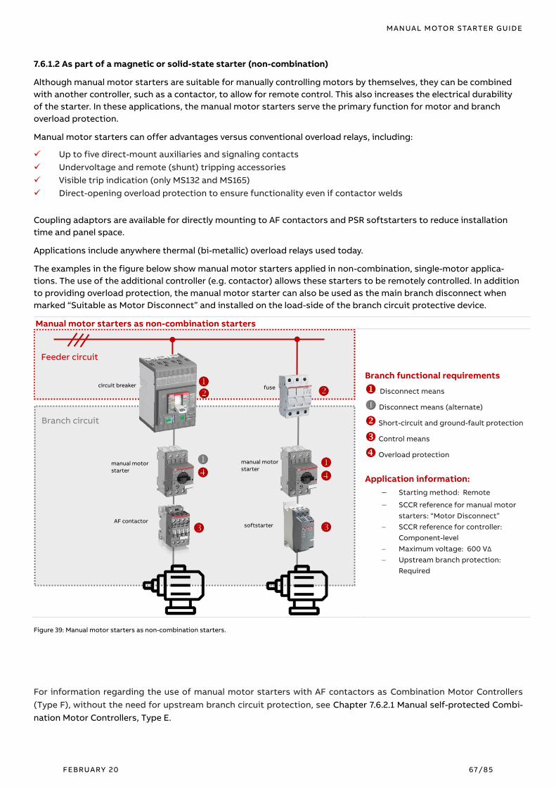
MANUAL MOTOR STARTER GUIDE
FEBRUARY 20 67/85
7.6.1.2 As part of a magnetic or solid-state starter (non-combination)
Although manual motor starters are suitable for manually controlling motors by themselves, they can be combined
with another controller, such as a contactor, to allow for remote control. This also increases the electrical durability
of the starter. In these applications, the manual motor starters serve the primary function for motor and branch
overload protection.
Manual motor starters can offer advantages versus conventional overload relays, including:
✓ Up to five direct-mount auxiliaries and signaling contacts
✓ Undervoltage and remote (shunt) tripping accessories
✓ Visible trip indication (only MS132 and MS165)
✓ Direct-opening overload protection to ensure functionality even if contactor welds
Coupling adaptors are available for directly mounting to AF contactors and PSR softstarters to reduce installation
time and panel space.
Applications include anywhere thermal (bi-metallic) overload relays used today.
The examples in the figure below show manual motor starters applied in non-combination, single-motor applica-
tions. The use of the additional controller (e.g. contactor) allows these starters to be remotely controlled. In addition
to providing overload protection, the manual motor starter can also be used as the main branch disconnect when
marked “Suitable as Motor Disconnect” and installed on the load-side of the branch circuit protective device.
Manual motor starters as non-combination starters
Branch functional requirements
Disconnect means
Disconnect means (alternate)
Short-circuit and ground-fault protection
Control means
Overload protection
Application information:
− Starting method: Remote
− SCCR reference for manual motor
starters: “Motor Disconnect” − SCCR reference for controller:
Component-level
− Maximum voltage: 600 VΔ
− Upstream branch protection:
Required
Figure 39: Manual motor starters as non-combination starters.
For information regarding the use of manual motor starters with AF contactors as Combination Motor Controllers
(Type F), without the need for upstream branch circuit protection, see Chapter 7.6.2.1 Manual self-protected Combi-
nation Motor Controllers, Type E.
Feeder circuit
Branch circuit
circuit breaker
manual motor
starter
fuse
manual motor
starter
AF contactor softstarter

MANUAL MOTOR STARTER GUIDE
FEBRUARY 20 68/85
7.6.1.3 Local motor disconnect
acc. to NEC Article 430.102 / CEC Section 28-604
The North American installation standards require that each motor circuit includes a means of safely disconnecting
the motor from its supply power. This is typically utilized for maintenance purposes. With very few exceptions, this
disconnect means must not exceed a distance of 15 m (50 ft.) in the U.S. and 9 m (29.5 ft.) in Canada from the motor
itself and must be within sight of the installation. If the primary disconnect means does not meet these criteria, a
secondary, local disconnect must be installed, often in the form of an enclosed switch.
Manual motor starters, when additionally marked “Suitable as Motor Disconnect”, are suitable for providing a means
of locally disconnecting the motor. The inclusion of an at-motor overload trip indication and reset feature can allow
for quick and simple diagnostic troubleshooting and maintenance, reducing downtime. At-motor short-circuit pro-
tection also help to mitigate fault detection issues caused by the increased wire impedance of long motor cables.
The ABB manual motor starter handles feature a trip-free mechanism, meaning the device will trip even if the handle
is locked in the ON position or held by hand. They are capable of being locked in the OFF position directly, and acces-
sory enclosures and through-door handles are available that meet the requirements for lock-out / tag-out and are 3x
padlock able.
Manual motor starters provide advantages versus conventional non-fusible disconnect switches, including:
- Local at-motor overload, short-circuit, and phase loss protection
- Undervoltage and remote (shunt) tripping accessories
- Lockable device handles without accessory (excludes Type MS116)
- Reduced downtime by providing greater diagnostic capabilities on location
Local motor disconnects are common in material handling applications, such as conveyors, but can also be found in
industrial applications employing centralized motor control centers.
Manual motor starters as local motor disconnects
Branch functional requirements
Disconnect means
Short-circuit and ground-fault protection
Control means
Overload protection
Overload protection (alternate)
Local motor disconnect
Application information:
− SCCR reference for manual motor
starters: “Motor Disconnect”
− Maximum voltage: 600 VΔ − Upstream branch protection: Required
Figure 40: Manual motor starters as non-combination starters.
Feeder circuit
Branch circuit
ABB enclosed
starter
manual
motor
starter
ABB motor
control center
manual
motor
starter
* *
≤50 ft.
*

MANUAL MOTOR STARTER GUIDE
FEBRUARY 20 69/85
7.7.1.4 Group installations
A group installation is defined as two or more motors, or one or more motors and other loads, protected by a single
branch circuit protective device (BCPD). Group installations help to reduce required panel space, waste heat in the
panel and cost. Group installations are permissible under NEC Article 430.53 in three instances, when either:
1. Several motors, each not exceeding 1 hp in rating, shall be permitted on a nominal 120 V branch circuit
protected at not over 20 A s or a branch circuit of 1000 V, nominal, or less, protected at not over 15 am-
peres. The full-load rating of each motor does not exceed 6 A.
Figure 41: Group installation 430.53(A) *250% According NEC 240.6 and 430.62(A)
2. Each motor circuit is individually protected against overload, with the BCPD sized for the smallest motor
in accordance with individual branch requirements. The BCPD should not open under normal operating
conditions for any load.
Figure 42: Group installation
3. Each load is controlled, and each motor protected against overload conditions by devices listed for use in
group installations. The BCPD must additionally be sized properly to protect the group. As an exception,
the controllers and overload protection do not need to be listed for use in group installations if the
upstream BCPD does not exceed the maximum size allowed for the individual motor circuit.
Figure 43: Group installation 430.53(B)
Feeder circuit
Branch circuit
BCPD Circuit
breaker
6 A (1 hp) 5 A 2 A
13 A
In = 2.5* x 6 A = 15 A
manual
motor
starter
Feeder circuit
Branch circuit
BCPD Circuit
breaker
In = 10 A
Ii = 150 A
In = 10 A
Ii = 150 A
In = 6 A
Ii = 78.8 A
26 A
In = 40 A
Ii = 75 A
manual
motor
starter
Feeder circuit
Branch circuit
BCPD Circuit
breaker
1 A 2 A 10 A
13 A
In = 12 A
MMS
8 … 12 A MMS
1.6 … 2.5 A
MMS
0.63 … 1 A
Motors
< 1 hp
Motors
> 1 hp

MANUAL MOTOR STARTER GUIDE
FEBRUARY 20 70/85
In all instances, the individual load tap conductors must have an ampacity of at least 125% of the motor full-load
current. If the distance from the BCPD to the individual motor overload protection is not greater than 7.5 meters (25
feet), the tap conductors can be reduced to ⅓ the ampacity of the branch conductors. For longer distances, the
ampacity of the individual load tap conductors must be equal to the branch circuit conductors. When the individual
load tap conductors are sized less than the branch circuit conductors, they must be protected from physical damage
by being enclosed in a raceway or another approved method.
Group installations are typically employed in Industrial Control Panels designed to control multiple motors and other
loads. Examples include a set of similarly sized loads (e.g. a fan bank), or a combination of a large main load and
smaller support loads (e.g. lubrication pumps or cooling fans).
ABB manual motor starters are suitable for use in group installations, and provide:
✓ An individual, lockable disconnect means for each load circuit
✓ Quick and compact group wiring using accessories like three-phase busbars and coupling adaptors
Branch functional requirements
Disconnect means
Short-circuit and ground-fault protection
Control means
Overload protection
Application information:
− SCCR reference for manual motor
starter: “Group Installation”
− SCCR ref. for controllers: Component-
level
− Maximum voltage: 600 VΔ
− Upstream branch protection: Required
Figure 44: Manual motor starters in a group installation.
Not < 1 3ൗ ampacity of
the branch circuit
conductors
Feeder circuit
Branch circuit
BCPD
Circuit
breaker
manual
motor
starter
AF
contactor
Tap conductors
(≤ 25 ft.)
AF reversing
starter

MANUAL MOTOR STARTER GUIDE
FEBRUARY 20 71/85
7.6.1.5 Tap conductor protection in group installations
Please note as of the date of this publication, the following application is not applicable in Canada under CSA C22.1
The Canadian Electrical Code (CEC), Section 28.
When manual motor starters are employed in standard group installations, their ability to protect against short- cir-
cuits is not taken into consideration. In an effort to credit these devices for protection against short- circuits, the
National Electrical Code® (NEC) allows manual motor starters marked “Suitable for Tap Conductor Protection in
Group Installations” to protect the individual group taps, instead of the upstream group BCPD. This allows the size of
the individual tap conductors to be smaller and more cost-effective than in standard group installations, as well as
the potential for larger groups and for greater disparity between individual load sizes.
When the individual load tap conductors do not exceed a distance of 3 meters (10 feet) from the BCPD before termi-
nating to a manual motor starter marked “Suitable for Tap Conductor Protection in Group Installations”, they are
allowed to be sized with and ampacity as low as 1/10 the rating of the upstream group BCPD.
The conductors between the manual motor starter and the load are sized based on the NEC rules for the load itself
and are no longer a factor of the branch circuit conductor ampacity as they are in standard group installations.
Manual motor starters marked “Suitable for Tap Conductor Protection in Group Installations” can additional be used
for the overcurrent protection of control transformers, eliminating the need for fuses or a UL 489 / CSA C22.2 No.5
circuit-breaker.
Tap conductor protection offers advantages versus conventional group installations, including:
✓ Smaller and more cost-effective wire sizes between the BCPD and each individual load
✓ Larger groups with greater disparity between load sizes
✓ Protection of control transformers
Manual motor starters for tap conductor protection in group installations
Branch functional requirements
Disconnect means
Short--circuit and ground-fault protection
Tap conductor protection
Control means
Overload protection
Application information:
− SCCR reference for manual motor starters:
“Tap Conductor Protection”
− Maximum voltage: 600 VΔ
− Upstream branch protection: Required
Figure 45: Manual motor starters for tap conductor protection in group installations.
Feeder circuit
Branch circuit
BCPD e.g. 200A
circuit
breaker
manual
motor
starter
Tap conductors (≤ 10 ft.)
softstarter
Sized based
on the load
Ampacity not < 1 10ൗ
the rating of the BCPD

MANUAL MOTOR STARTER GUIDE
FEBRUARY 20 72/85
7.6.2 Defining Combination Motor Controllers (NKJH)
A Combination Motor Controller (CMC) is a single device, or assembly of devices, which provides the combined func-
tions of branch circuit disconnect means, short-circuit protection, control means, and overload protection. These
are:
− Listed combinations tested according to UL 60947-4-1 and CSA C22.2 No.60947-4-1
− Tested in a single enclosure
− Tested for a complete branch short-circuit current rating; Type 1 or Type 2 coordination
Figure 467: Defining Combination Motor Controllers (NKJH).
The figure below shows the currently six construction types for Combination Motor Controllers. Manual motor start-
ers are used for Types E and F.
Tested in an enclosure Type A Type B Type C Type D Type E Type F
(two-component)
Type F
(three-component)
Disconnect
means
Motor
disconnect
UL 98 or UL 489
Motor
disconnect
UL 98 or UL 489 Inverse-time
circuit-breaker
UL 489
Instantaneous
trip
circuit-breaker
UL 489
Self-protected
control device
UL 60947-4-1
Manual
self-protected
combination
controller
UL 60947-4-1
Manual
self-protected
combination
controller
UL 60947-4-1
Short-circuit
and ground-
fault protec-
tion
Fuses
UL 248
Motor short-cir-
cuit protector
UL 60947-4-1
Control means
Magnetic or
solid-state
motor controller
UL 60947-4-1
Magnetic or
solid-state
motor controller
UL 60947-4-1
Magnetic or
solid-state
motor controller
UL 60947-4-1
Magnetic or
solid-state
motor controller
UL 60947-4-1
Magnetic or
solid-state
motor controller
UL 60947-4-1
Magnetic or
solid-state
motor controller
UL 60947-4-1
Overload pro-
tection
Overload relay
UL 60947-4-1
Overload relay
UL 60947-4-1
Overload relay
UL 60947-4-1
Overload relay
UL 60947-4-1
Manual
self-protected
combination
controller
UL 60947-4-1
Overload relay
UL 60947-4-1
Tested combi-
nation SCCR
Straight
voltage rated
(e.g. 480 Δ)
Straight
voltage rated
(e.g. 480 Δ)
Straight
voltage rated
(e.g. 480 Δ)
Straight
voltage rated
(e.g. 480 Δ)
Slash
voltage rated
(e.g. 480Y/277V)
Slash
voltage rated
(e.g. 480Y/277V)
Slash
voltage rated
(e.g. 480Y/277V)
_
Table 26: Defining Combination Motor Controllers (NKJH) Note: the information above is derived from UL 60947-4-1 and is intended for reference purposes
only.
A complete listing of ABB’s tested Combination Motor Controllers can be accessed online on UL’s website, using the keyword “ABB” (UL’s
website Link).

MANUAL MOTOR STARTER GUIDE
FEBRUARY 20 7 3/85
7.6.2.1 Manual self-protected Combination Motor Controllers, Type E
Type E represents the only CMC construction type to allow use of a single component. Manual motor starters are the
most common example. The term “self-protected” refers to the level of coordinated protection provided, as these
combinations are subject to an intense validation process following short- circuit, including thousands of electrical
and mechanical operations. For this reason, Type E Combination Motor Controllers ensure proven continuity of ser-
vice following a fault and provide a level of coordinated protection that exceeds even Type 2.
Due to the compact nature of manual motor starters, Type E Combination Motor Controllers are slash voltage rated
(e.g. 600Y/347 V AC). This limits their use to solidly grounded networks for the higher voltages (e.g. above 347 V AC).
Two additional criteria exist for manual motor starters certified as Combination Motor Controllers:
Line-side terminal spacing of 2 inches over-surface (creepage) and 1 inch through-air (clearance) which are similar to
the requirements common for UL 489 / CSA C22.2 No.5 circuit-breakers.
A means of visibly differentiating between thermal (overload) and magnetic (short-circuit) trip, so as not to inhibit
troubleshooting.
These requirements can be met using either accessories (e.g., terminal feeder blocks and side-mount trip indicators)
or inherent design features. MS165 requires no additional accessories to meet the above criteria; MS132 requires only
the line-side terminal feeder block (S1-M3-…). Both types feature an integral trip indicator window, which turns red
upon tripping of the instantaneous release, indicating a short- circuit.
✓ Type E manual self-protected Combination Motor Controllers provide significant advantages for customers by
incorporating control, disconnect, overload, and short-circuit protection into one, compact and cost-efficient
product.
Self-protected Combination Motor Controller (Type E)
Branch functional requirements
Disconnect means
Short-circuit and ground-fault protection
Control means
Overload protection
Application information:
− Starting method: Manual
− SCCR reference: “Type E”
− Maximum voltage: 600Y/347 V
− Upstream branch protection: Not
required
Figure 47: Manual self-protected Combination Motor Controller (Type E).
For information regarding manual starter applications in ungrounded (delta) networks above 347 V AC, see Chapter
7.6.1.1 Manual starters (non-combination).
Feeder circuit
Branch circuit
manual
motor
starter

MANUAL MOTOR STARTER GUIDE
FEBRUARY 20 74/85
7.6.2.2 Combination Motor Controllers, Type F
Type F constructions are divided into two styles: two-component and three-component assemblies. Two-component
Type F assemblies utilize a manual, self-protected device for both short- circuit and overload protection. Three-com-
ponent Type F assemblies utilize a separate overload relay, and short- circuit protection is provided by a magnetic
only (MO) manual motor starter.
The additional criteria for line-side terminal spacing and visible trip indication described in the chapter below are
also applicable for Type F Combination Motor Controllers.
Type F Combination Motor Controllers can be tested for either Type 1 or Type 2 coordination.
✓ With the inclusion of a contactors for remote control, Type F Combination Motor Controllers increase function-
ality while still offering customers the benefit of using compact and cost-efficient manual motor starters for
branch short- circuit protection.
✓ Three-component assemblies provide additional benefits, including selectable Class 10, 20, 30 overload protec-
tion (electronic), along with a wiring schematic identical to that of a conventional combination starter (e.g.
molded case circuit-breaker, contactor, and overload relay).
Combination Motor Controllers (Type F)
Branch functional requirements
Two-component assemblies on the left side and
three-component assemblies on the right.
Disconnect means
Short-circuit and ground-fault protection
Control means
Overload protection
Application information:
− Starting method: Remote
− SCCR reference: “Type F”
− Maximum voltage: 600Y/347 V
− Upstream branch protection: Not
required
Figure 48: Combination Motor Controllers (Type F)
For information regarding remote starter applications in ungrounded (delta) networks above 347 V AC, see Chapter
7.6.1.2 As part of a magnetic or solid-state starter (non-combination).
Feeder circuit
Branch circuit
AF contactor
manual
motor
starter
magnetic only
manual motor
starter
AF contactor
EF overload
relay

MANUAL MOTOR STARTER GUIDE
FEBRUARY 20 75/85
7.6.2.3 Protection of ABB Micro drives
Type E manual self-protected Combination Motor Controllers can be used for the protection of frequency converters
(e.g. variable frequency drives). This requires further component-level short- circuit testing to be performed accord-
ing to UL 508C. ABB has performed testing to allow the use of manual motor starters for the protection of ACS150
and ACS3xx Micro drives.
The additional criteria for line-side terminal spacing and visible trip indication described in Chapter 7.6.2.1 Manual
self-protected Combination Motor Controllers, Type E, are also required for the Type E manual self-protected Combi-
nation Motor Controllers used in this application.
✓ The use of manual motor starters for drive protection provides customers with a compact and cost-efficient
alternative to non-resettable semiconductor fuses.
Protection of ABB Micro drives
Branch functional requirements
Disconnect means
Short-circuit and ground-fault protection
Control means
Overload protection
Application information:
− Starting method: variable frequency
drive
− SCCR reference: component-level
− Maximum voltage: 480Y/277 V
− Upstream branch protection: not
required
Figure 49: Protection of ABB drives
For more information regarding ABB’s tested combinations with Type E manual self-protected Combination Motor Controllers and ACS150
/ ACS3xx Micro drives, please consult the relevant document, which can be accessed from the Download Center(https://library.abb.com).
Feeder circuit
Branch circuit
manual
motor
starter
micro
dirve

MANUAL MOTOR STARTER GUIDE
FEBRUARY 20 76/85
_
8. Glossary AC Alternating current
Active power The power consumed by the motor which is converted into mechanical action.
Ambient temperature Ambient temperature is the temperature of water, air or surrounding medium where the
equipment is used or stored.
DC Direct current.
Delta connection The connection type of a motor where the windings are connected in a delta.
Efficiency The ratio between mechanical output and electrical input. The percentage given indi-
cates how effective the motor is at converting electrical energy to mechanical energy.
Frequency The number of periodic cycles per unit of time.
FLA Full Load Amps, rated-current at rated-load and rated voltage. This is the amount of cur-
rent (amps) the motor will draw from the electrical system when producing its rated
output horsepower.
Icm Rated short-circuit making capacity, see also chapter: 2.2.2 Rated short-circuit making
capacity (Icm)
Icu Rated service short- circuit breaking capacity, see also chapter: 2.2.3.1 Rated ultimate
short-circuit breaking capacity (Icu) acc. to IEC / EN 60947-2.
Ics Rated service short-circuit breaking capacity, see also chapter: 2.2.3.2 Rated service
short-circuit breaking capacity (Ics) acc. to IEC / EN 60947-2.
Icw Rated short-time withstand current, see also Chapter: 2.2.4 Rated short-time withstand
current (Icw).
Ie The tripping characteristic of the instantaneous short-circuit releases is based on the
rated operational current Ie, which, in the case of the manual motor starter, is the same
as the upper value of the setting range.
IE3 Premium-efficiency class for single-speed motors according to IEC 60034-30.
IE4 Super Premium-efficiency class for single-speed motors according to IEC 60034-30 ver-
sion 2014
IEC International Electrotechnical Commission which is part of the International Standard Or-
ganization.
Inertia A measure of a body’s resistance to change in velocity whether the body is moving at a
constant speed or is at rest. The velocity can be rotational or linear.
Inrush peak A short, high-current transient occurring during the first milliseconds when the motor is
started.
LED Light-emitting diode.
Load torque The braking torque on the motor shaft caused by the load. If the braking torque is equal
or nearly equal to the rated motor torque it can be defined as high load torque.
MEPS Minimum Energy Performance Standard: a local regulation specifying the minimum re-
quired energy performance for energy-using products. In Europe the EU MEPS for direct
on-line motors is IE3.
MMS Manual motor starter.
N-end The end that is normally the non-drive end of an electrical motor.

MANUAL MOTOR STARTER GUIDE
FEBRUARY 20 77/85
NEMA The National Electrical Manufacturers Association (USA).
Network Several nodes connected to each other with some type of communication medium. A
network can be of single link type or multiple link type.
NLRV UL definition of a Manual Motor Controllers, see also Chapter: 7.6.1 Defining Manual Mo-
tor Controllers (NLRV).
NKJH UL definition of a Combination Motor Controllers, see also Chapter: 7.6.2 Defining Com-
bination Motor Controllers (NKJH).
Noise Unwanted disturbances in a communication medium that tend to obscure the data con-
tent.
Operational voltage The voltage that is fed to the motor, usually 3-phase.
Overload relay A device used to avoid overheating of the motor. It can be of electronic or thermal type.
Rated current The rated current is the current drawn by a fully loaded motor at its specified nominal
speed.
Reactive power The power consumed by the motor is used for the magnetization of the motor.
RMS Root Mean Square: The RMS value of an AC supply is the steady DC equivalent, which
would convert electrical energy to thermal energy at the same rate in each resistance.
SCCR Short-circuit Current Ratings, see also Chapter: 7.1.6 Selecting the right Short Circuit Cur-
rent Ratings (SCCR) level for your UL application
Tripping Class The tripping Class defines the starting time at a specific current before tripping occurs.
Different classes exist, for example, 10, 20, 30, etc. where class 30 allows the longest
starting time.
Ue Rated operation voltage, see also Chapter: 2.2.1 Rated operational voltage (Ue).

MANUAL MOTOR STARTER GUIDE
FEBRUARY 20 78/85
9. Appendix A.1 Group installation worksheet
The worksheet below can be used for sizing devices for group installation. The rules shown to the far right are
applicable only for devices suitable for tap conductor protection in group installations. Recommended worksheet
procedure: 1. Determine branch conductor size; 2. Determine BCPD size; 3. Specify distances; 4. Determine
individual tap conductor size.
Feeder
SCPD
BCPD
____ A
MMS MMS MMS
Contactor Contactor
Not > 3 meters
(10 feet) to BCPD 2 acc. NEC 430.53(D)(3)
*
__ AWG
Listed as “Suitable
for Tap Conductor
Protection in Group
Installations” 2 acc. NEC 430.53(D)(3)
Sized at 125%
the motor full-
load current
(FLC) 2 acc. NEC 430.53(D)(3)
Sized at 125% the
motor FLC, and
not less than 1/10
the rating of the
BCPD 2 acc. NEC 430.53(D)(3)
__ A
WG
__ A
WG
__ A
WG
__ A
WG
__ A
WG
__ A
WG
__ A
WG
__ A
WG
Not > 7.5 meters (25
feet) to BCPD acc. NEC 430.53(D)(2)
*
Listed as
“Suitable for use in
group installations” acc. NEC 430.53(C)(1)&(2)
Listed as
“Suitable for use in
group installations”,
or protected by a BCPD
not greater than the
maximum allowed per
Table 430.52
[400% c.b./ 300% fuses] acc. NEC 430.52(C)(2)
FLC: ___ A
Branch conductors sized for the total group Largest load ____ A x 1.25 + remaining loads ____ A = _____ A acc. NEC 430.24
BCPD sized to protect the group installation
Circuit breakers: Largest load ____ A x 2.5 + remaining loads ____ A = _____ A (round-down1) → _____ A
Fuses: Largest load ____ A x 1.75 + remaining loads ____ A = ______ A (round-down1) → _____ A
acc. NEC 430.53(C)(4) 1
Standard Ampere ratings for fuses and inverse time circuit breakers:
15, 20, 25, 30, 35, 40, 45, 50, 60, 70, 80, 90, 100, 110, 125, 150, 175, 200, … A acc. NEC 240.6(A)
__________ V
__________ Φ _
_ m
( _
__ ft.
)
__
m (
___ ft.
)
__
m (
___ ft.
)
Sized at 125% the
motor FLC, and not
less than 1/3 the
ampacity of the
Branch conductors acc. NEC 430.53(D)(2)
FLC: ___ A FLC: ___ A
For lengths greater than speci-
fied, individual motor tap
conductors must have an ampacity
equal to the branch conductors
(excluding those on the load side
of devices suitable for tap conduc-
tor protection) acc. NEC 430.53(D)(1)
2 Applicable only for devices suita-
ble for tap conductor protection
in group installations When this calculation re-
sults in a BCPD rating less than
the ampacity of the branch con-
ductors, it is permitted to
increase the size of the overcur-
rent device to the next standard
Ampere rating 1 above the am-
pacity of these conductors acc. NEC 430.53(C)(4), 240.4(B)
** **
*
**
…or…

MANUAL MOTOR STARTER GUIDE
FEBRUARY 20 79/85
Below is an example of a calculation for a group installation.
Feeder
SCPD
BCPD
____ A
MMS MMS MMS
Contactor Contactor
Not > 3 meters
(10 feet) to BCPD 2 acc. NEC 430.53(D)(3)
*
__ AWG
Listed as “Suitable
for Tap Conductor
Protection in Group
Installations” 2 acc. NEC 430.53(D)(3)
Sized at 125%
the motor full-
load current
(FLC) 2 acc. NEC 430.53(D)(3)
Sized at 125% the
motor FLC, and
not less than 1/10
the rating of the
BCPD 2 acc. NEC 430.53(D)(3)
__ A
WG
__ A
WG
__ A
WG
__ A
WG
__ A
WG
__ A
WG
__ A
WG
__ A
WG
Not > 7.5 meters (25
feet) to BCPD acc. NEC 430.53(D)(2)
*
Listed as
“Suitable for use in
group installations” acc. NEC 430.53(C)(1)&(2)
Listed as
“Suitable for use in
group installations”,
or protected by a BCPD
not greater than the
maximum allowed per
Table 430.52
[400% c.b./ 300% fuses] acc. NEC 430.52(C)(2)
FLC: ___ A
Branch conductors sized for the total group Largest load ____ A x 1.25 + remaining loads ____ A = _____ A acc. NEC 430.24
BCPD sized to protect the group installation
Circuit breakers: Largest load ____ A x 2.5 + remaining loads ____ A = _____ A (round-down1) → _____ A
Fuses: Largest load ____ A x 1.75 + remaining loads ____ A = ______ A (round-down1) → _____ A
acc. NEC 430.53(C)(4) 1
Standard Ampere ratings for fuses and inverse time circuit breakers:
15, 20, 25, 30, 35, 40, 45, 50, 60, 70, 80, 90, 100, 110, 125, 150, 175, 200, … A acc. NEC 240.6(A)
__________ V
__________ Φ
__
m (
___ ft.
)
__
m (
___ ft.
)
__
m (
___ ft.
)
Sized at 125% the
motor FLC, and not
less than 1/3 the
ampacity of the
Branch conductors acc. NEC 430.53(D)(2)
FLC: ___ A FLC: ___ A
For lengths greater than speci-
fied, individual motor tap
conductors must have an ampacity
equal to the branch conductors
(excluding those on the load side
of devices suitable for tap conduc-
tor protection) acc. NEC 430.53(D)(1)
2 Applicable only for devices suita-
ble for tap conductor protection
in group installations
When this calculation re-
sults in a BCPD rating less than
the ampacity of the branch con-
ductors, it is permitted to
increase the size of the overcur-
rent device to the next standard
Ampere rating 1 above the am-
pacity of these conductors acc. NEC 430.53(C)(4), 240.4(B)
** **
*
**
…or…
50 480
50 3 13 138 125
13 87.5 90
50 13 75.5
125
4
2 6
6 6
10
10
10
2
14
14
14
3
50 10 3
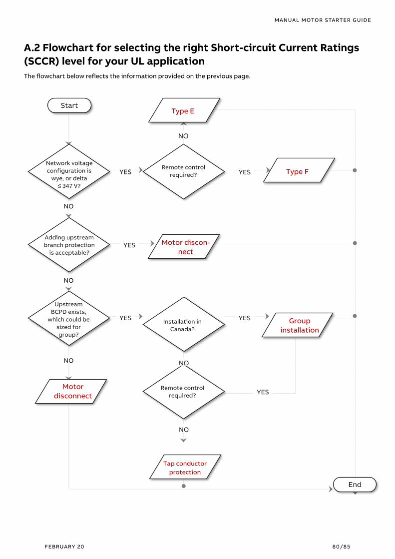
MANUAL MOTOR STARTER GUIDE
FEBRUARY 20 80/85
A.2 Flowchart for selecting the right Short-circuit Current Ratings
(SCCR) level for your UL application
The flowchart below reflects the information provided on the previous page.
Start
Network voltage
configuration is
wye, or delta
≤ 347 V?
Adding upstream
branch protection
is acceptable?
Upstream
BCPD exists,
which could be
sized for
group?
Remote control
required?
Installation in
Canada?
Remote control
required?
Motor discon-
nect
Type E
Type F
Motor
disconnect
Group
installation
End
NO
NO
NO NO
Tap conductor
protection
NO
YES
YES
YES
YES
YES
YES
NO

MANUAL MOTOR STARTER GUIDE
FEBRUARY 20 81/85
A.3 Frequently asked questions (FAQ)
Question: Why do Type E and Type F assemblies require larger terminal spacings (e.g. line-side terminal feeder
block)?
Answer: When manual motor starters are certified as Combination Motor Controllers, they replace standard
molded case circuit breakers for branch short-circuit protection. UL 489 / CSA C22.2 No.5 circuit breakers
are required to have greater creepage and clearance distances between terminals, a requirement which is
then extended to the manual motor starters for Type E and Type F assemblies.
Question: Why not simply use Type E or Type F ratings for all applications?
Answer: These ratings are limited to applications in solidly grounded networks with line-to-ground voltages
not exceeding 347 V AC. The addition of an upstream branch circuit protective device increases the voltage
rating of manual motor starters to 600 V AC in either grounded or ungrounded networks.
Question: Why are manual motor starters not just tested as circuit breakers acc. to UL 489 / CSA C22.2 No.5?
Answer: UL 489 / CSA C22.2 No.5 circuit breakers are only suitable for providing overload protection for mo-
tors less than 1 hp (2.1 Amps at 480 V AC). This would significantly limit the advantages of manual motor
starters in motor applications.
Question: Can manual motor starters be used in lighting applications?
Answer: According to UL 508A Ed.2, Table 33.1, controllers carrying “AC Motor” ratings (e.g. manual motor
starters) can be used for the control of AC fluorescent ballast loads. When applied using this standard, man-
ual motor starters are suitable for the control of lamp loads only.
Question: Do I need to use a separate S803W current limiter for each individual manual motor starter?
Answer: One S803W can be used to increase SCCR for multiple MMS, as long as the sum of the load currents
do not exceed the rated current of the S803W. Three variants are available for 32, 63, and 100 Amps.
Question: Can manual motor starters be used in heating applications?
Answer: Manual motor starters carry AC-1 General use ratings, which apply when controlling heaters. Mag-
netic only (MO) manual motor starters can be used if additional overload protection is not required.
Question: Can I use accessories like busbar and feeder terminals without effecting the SCCR?
Answer: ABB accessory three-phase busbar and feeder blocks have been validated to correspond to the max-
imum SCCR for the manual motor starters; there is no derating for use of these accessories.
Question: Are there any mitigation techniques for issues with shaft alignment?
Answer: Compact MMS may require the use of longer shafts to reach the panel door. For issues with shaft
alignment, use of the MSHA1 shaft supporter and MSH-AR shaft alignment ring is recommended.
Question: Can I substitute between upstream protective devices without effecting the SCCR?
Answer: For component-level SCCR, upstream protection can be substituted with any like device, assuming
the I2t and Ip values of the substitute are equal to or lower than the original component (e.g. substituting
Class J fuses for Class RK5). For Combination Motor Controllers, substitutions are not allowed.
Question: Does the upstream protection for a group installation need to be included in the same enclosure?
Answer: No – but any tap leaving an enclosure must be suitably protected (e.g. in conduit).

MANUAL MOTOR STARTER GUIDE
FEBRUARY 20 82/85
A.4 Motor rated operational powers and currents
The currents given below concern standard three-phase four-pole cage motors (1500 r.p.m. at 50 Hz 1800 r.p.m. at 60
Hz). These values are given for guidance and may vary according to the motor manufacturer and depending on the
number of poles
IEC Motor nominal current: standardized values in grey (according to IEC 60947-4-1 Annex G)
Motor
power 220 V 230 V 240 V 380 V 400 V 415 V 440 V 500 V 660 V 690 V
kW A A A A A A A A A A
0.06 0.37 0.35 0.34 0.21 0.2 0.19 0.18 0.16 0.13 0.12
0.09 0.54 0.52 0.50 0.32 0.3 0.29 0.26 0.24 0.18 0.17
0.12 0.73 0.7 0.67 0.46 0.44 0.42 0.39 0.32 0.24 0.23
0.18 1 1 1 0.63 0.6 0.58 0.53 0.48 0.37 0.35
0.25 1.6 1.5 1.4 0.9 0.85 0.82 0.74 0.68 0.51 0.49
0.37 2.0 1.9 1.8 1.2 1.1 1.1 1 0.88 0.67 0.64
0.55 2.7 2.6 2.5 1.6 1.5 1.4 1.3 1.2 0.91 0.87
0.75 3.5 3.3 3.2 2.0 1.9 1.8 1.7 1.5 1.15 1.1
1.1 4.9 4.7 4.5 2.8 2.7 2.6 2.4 2.2 1.7 1.6
1.5 6.6 6.3 6 3.8 3.6 3.5 3.2 2.9 2.2 2.1
2.2 8.9 8.5 8.1 5.2 4.9 4.7 4.3 3.9 2.9 2.8
3 11.8 11.3 10.8 6.8 6.5 6.3 5.7 5.2 4 3.8
4 15.7 15 14.4 8.9 8.5 8.2 7.4 6.8 5.1 4.9
5.5 20.9 20 19.2 12.1 11.5 11.1 10.1 9.2 7 6.7
7.5 28.2 27 25.9 16.3 15.5 14.9 13.6 12.4 9.3 8.9
11 39.7 38 36.4 23.2 22 21.2 19.3 17.6 13.4 12.8
15 53.3 51 48.9 30.5 29 28 25.4 23 17.8 17
18.5 63.8 61 58.5 36.8 35 33.7 30.7 28 22 21
22 75.3 72 69 43.2 41 39.5 35.9 33 25.1 24
30 100 96 92 57.9 55 53 48.2 44 33.5 32
37 120 115 110 69 66 64 58 53 40.8 39
45 146 140 134 84 80 77 70 64 49.1 47
55 177 169 162 102 97 93 85 78 59.6 57
75 240 230 220 139 132 127 116 106 81 77
90 291 278 266 168 160 154 140 128 97 93
110 355 340 326 205 195 188 171 156 118 113
132 418 400 383 242 230 222 202 184 140 134
160 509 487 467 295 280 270 245 224 169 162
200 637 609 584 368 350 337 307 280 212 203
250 782 748 717 453 430 414 377 344 261 250
315 983 940 901 568 540 520 473 432 327 313
355 1109 1061 1017 642 610 588 535 488 370 354
400 1255 1200 1150 726 690 665 605 552 418 400
500 1545 1478 1416 895 850 819 745 680 515 493
560 1727 1652 1583 1000 950 916 832 760 576 551
630 1928 1844 1767 1116 1060 1022 929 848 643 615
710 2164 2070 1984 1253 1190 1147 1043 952 721 690
800 2446 2340 2243 1417 1346 1297 1179 1076 815 780
900 2760 2640 2530 1598 1518 1463 1330 1214 920 880
1000 3042 2910 2789 1761 1673 1613 1466 1339 1014 970

MANUAL MOTOR STARTER GUIDE
FEBRUARY 20 83/85
UL/CSA Motor nominal current: single and three-phase, standardized values in grey (according to UL 60947-4-1A)
Motor
power
120 V
1-ph
200 V
1-ph
200 V
3-ph
208 V
1-ph
208 V
3-ph
220-
240 V
1-ph
220-
240 V
3-ph
380-
415 V
3-ph
440-
480 V
3-ph
550-
600 V
3-ph
hp A A A A A A A A A
1/10 3 – – – 1.5 – – – –
1/8 3.8 – – – 1.9 – – – –
1/6 4.4 2.5 – 2.4 – 2.2 – – – –
1/4 5.5 3.3 – 3.2 – 2.9 – – – –
1/3 7.2 4.1 – 4 – 3.6 – – – –
1/2 9.8 5.6 2.5 5.4 2.4 4.9 2.2 1.3 1.1 0.9
3/4 13.8 7.9 3.7 7.6 3.5 6.9 3.2 1.8 1.6 1.3
1 16 9.2 4.8 8.8 4.6 8 4.2 2.3 2.1 1.7
1-1/2 20 11.5 6.9 11 6.6 10 6 3.3 3 2.4
2 24 13.8 7.8 13.2 7.5 12 6.8 4.3 3.4 2.7
3 34 19.6 11 18.7 10.6 17 9.6 6.1 4.8 3.9
5 56 32.2 17.5 30.8 16.7 28 15.2 9.7 7.6 6.1
7-1/2 80 46 25.3 44 24.2 40 22 14 11 9
10 100 57.5 32.2 55 30.8 50 28 18 14 11
15 135 - 48.3 – 46.2 68 42 27 21 17
20 – – 62.1 – 59.4 88 54 34 27 22
25 – – 78.2 – 74.8 110 68 44 34 27
30 – – 92 – 88 136 80 51 40 32
40 – – 120 – 114 176 104 66 52 41
50 – – 150 – 143 216 130 83 65 52
60 – – 177 – 169 – 154 103 77 62
75 – – 221 – 211 – 192 128 96 77
100 – – 285 – 273 – 248 165 124 99
125 – – 359 – 343 – 312 208 156 125
150 – – 414 – 396 – 360 240 180 144
200 – – 552 – 528 – 480 320 240 192
250 – – – – – – 604 403 302 242
300 – – – – – – 722 482 361 289
350 – – – – – – 828 560 414 336
400 – – – – – – 954 636 477 382
450 – – – – – – 1030 – 515 412
500 – – – – – – 1180 786 590 472

MANUAL MOTOR STARTER GUIDE
FEBRUARY 20 84/85
Nominal efficiency limits defined in IEC 60034-30-1:2014 (reference values at 50 Hz, based on test methods specified in IEC 60034-2-1:2014).
Output IE1
Standard efficiency
IE2
High efficiency
IE3
Premium efficiency
IE4
Super Premium efficiency
kW 2 pole 4 pole 6 pole 8 pole 2 pole 4 pole 6 pole 8 pole 2 pole 4 pole 6 pole 8 pole 2 pole 4 pole 6 pole 8 pole
0.12 45.0 50.0 38.3 31.0 53.6 59.1 50.6 39.8 60.8 64.8 57.7 50.7 66.5 69.8 64.9 62.3
0.18 52.8 57.0 45.5 38.0 60.4 64.7 56.6 45.9 65.9 69.9 63.9 58.7 70.8 74.7 70.1 67.2
0.20 54.6 58.5 47.6 39.7 61.9 65.9 58.2 47.4 67.2 71.1 65.4 60.6 71.9 75.8 71.4 68.4
0.25 58.2 61.5 52.1 43.4 64.8 68.5 61.6 50.6 69.7 73.5 68.6 64.1 74.3 77.9 74.1 70.8
0.37 63.9 66.0 59.7 49.7 69.5 72.7 67.6 56.1 73.8 77.3 73.5 69.3 78.1 81.1 78.0 74.3
0.40 64.9 66.8 61.1 50.9 70.4 73.5 68.8 57.2 74.6 78.0 74.4 70.1 78.9 81.7 78.7 74.9
0.55 69.0 70.0 65.8 56.1 74.1 77.1 73.1 61.7 77.8 80.8 77.2 73.0 81.5 83.9 80.9 77.0
0.75 72.1 72.1 70.0 61.2 77.4 79.6 75.9 66.2 80.7 82.5 78.9 75.0 83.5 85.7 82.7 78.4
1.1 75.0 75.0 72.9 66.5 79.6 81.4 78.1 70.8 82.7 84.1 81.0 77.7 85.2 87.2 84.5 80.8
1.5 77.2 77.2 75.2 70.2 81.3 82.8 79.8 74.1 84.2 85.3 82.5 79.7 86.5 88.2 85.9 82.6
2.2 79.7 79.7 77.7 74.2 83.2 84.3 81.8 77.6 85.9 86.7 84.3 81.9 88.0 89.5 87.4 84.5
3 81.5 81.5 79.7 77.0 84.6 85.5 83.3 80.0 87.1 87.7 85.6 83.5 89.1 90.4 88.6 85.9
4 83.1 83.1 81.4 79.2 85.8 86.6 84.6 81.9 88.1 88.6 86.8 84.8 90.0 91.1 89.5 87.1
5.5 84.7 84.7 93.1 81.4 87.0 87.7 86.0 83.8 89.2 89.6 88.0 86.2 90.9 91.9 90.5 88.3
7.5 86.0 86.0 84.7 83.1 88.1 88.7 87.2 85.3 90.1 90.4 89.1 87.3 91.7 92.6 91.3 89.3
11 87.6 87.6 86.4 85.0 89.4 89.8 88.7 86.9 91.2 91.4 90.3 88.6 92.6 93.3 92.3 90.4
15 88.7 88.7 87.7 86.2 90.3 90.6 89.7 88.0 91.9 92.1 91.2 89.6 93.3 93.9 92.9 91.2
18.5 89.3 89.3 88.6 86.9 90.9 91.2 90.4 88.6 82.4 92.6 91.7 90.1 93.7 94.2 93.4 91.7
22 89.9 89.9 89.2 87.4 91.3 91.6 90.9 89.1 92.7 93.0 92.2 90.6 94.0 94.5 93.7 92.1
30 90.7 90.7 90.2 88.3 92.0 92.3 91.7 89.8 93.3 93.6 92.9 91.3 94.5 94.9 94.2 92.7
37 91.2 91.2 90.8 88.8 92.5 92.7 92.2 90.3 93.7 93.9 93.3 91.8 94.8 95.2 94.5 93.1
45 91.7 91.7 91.4 89.2 92.9 93.1 92.7 90.7 94.0 94.2 93.7 92.2 95.0 95.4 94.8 93.4
55 92.1 92.1 91.9 89.7 93.2 93.5 93.1 91.0 94.3 94.6 94.1 92.5 95.3 95.7 95.1 93.7
75 92.7 92.7 92.6 90.3 93.8 94.0 93.7 91.6 94.7 95.0 94.6 93.1 95.6 96.0 95.4 94.2
90 93.0 93.0 92.9 90.7 94.1 94.2 94.0 91.9 95.0 95.2 94.9 93.4 95.8 96.1 95.6 94.4
110 93.3 93.3 93.3 91.1 94.3 94.5 94.3 92.3 95.2 95.4 95.1 93.7 96.0 96.3 95.8 94.7
132 93.5 93.5 93.5 91.5 94.6 94.7 94.6 92.6 95.4 95.6 95.4 94.0 96.2 96.4 96.0 94.9
160 93.8 93.8 93.8 91.9 94.8 94.9 94.8 93.0 95.6 95.8 95.6 94.3 96.3 96.6 96.2 95.1
200 94.0 94.0 94.0 92.5 95.0 95.1 95.0 93.5 95.8 96.0 95.8 94.6 96.5 96.7 96.3 95.4
250 94.0 94.0 94.0 92.5 95.0 95.1 95.0 93.5 95.8 96.0 95.8 94.6 96.5 96.7 96.5 95.4
315 94.0 94.0 94.0 92.5 95.0 95.1 95.0 93.5 95.8 96.0 95.8 94.6 96.5 96.7 96.6 95.4
355 94.0 94.0 94.0 92.5 95.0 95.1 95.0 93.5 95.8 96.0 95.8 94.6 96.5 96.7 96.6 95.4
400 94.0 94.0 94.0 92.5 95.0 95.1 95.0 93.5 95.8 96.0 95.8 94.6 96.5 96.7 96.6 95.4
450 94.0 94.0 94.0 92.5 95.0 95.1 95.0 93.5 95.8 96.0 95.8 94.6 96.5 96.7 96.6 95.4

ABB STOTZ-KONTAKT GmbH
Eppelheimer Straße 82
69123 Heidelberg, Germany
Phone: +49 (0) 6221 701-0
Fax: +49 (0) 6221 701-1325
E-Mail: [email protected]
You can find the address of your local sales organiza-
tion on the ABB home page
http://www.abb.com/contacts -> Low-voltage products
Note
We reserve the right to make technical changes or modify
the contents of this document without prior notice.
About purchase orders, the agreed particulars shall pre-
vail. ABB does not accept any responsibility whatso-ever
for potential errors or possible lack of information in this
document.
Exclusion of liability
ABB is not responsible for the implementation, verifica-
tion and validation of the overall safety system. It is the
responsibility of the system integrator (or other party)
who is responsible for the overall system and system
safety. The system integrator (or other responsible
party) must make sure that the entire implementation
complies with all relevant standards, directives and local
electrical code, and that the system is tested, verified
and validated correctly.
We reserve all rights in this document and in the subject
matter and illustrations contained therein. Any reproduc-
tion, disclosure to third parties or utilization of its
contents - in whole or in parts – is forbidden without the
prior written consent of ABB.
© Copyright 2021 ABB. All rights reserved. Specifications
subject to change without notice.
2C
DC
1310
60
M0
20
2 r
ev.
C (
05
.20
21)