manual of dv36 - legend gas fires - defining luxury and...
TRANSCRIPT

Owners Manual of direct-vent gas fireplace DV36(NG) Legend fireplace co.,ltd
A B C D E F
mm 1248 942 873 993 420 445

2
Installers Guide
- Do not store or use gasoline or other flammable vapors and liquids in the vicinity of this or any other appliance. - What to do if you smell gas
• Do not try to light any appliance. • Do not touch any electrical switch. • Do not use any phone in your building. • Immediately call your gas supplier from a neighbor's phone. Follow the gas supplier's instructions. • If you cannot reach your gas supplier, call the fire department. - Installation and service must be performed by a qualified installer, service agency, or the gas supplier.
WARNING: IMPROPER INSTALLATION, ADJUSTMENT, ALTERATION, SERVICE OR MAINTENANCE CAN CAUSE INJURY OR PROPERTY DAMAGE. REFER TO THIS MANUAL. FOR ASSISTANCE OR ADDITIONAL INFORMATION CONSULT A QUALIFIED INSTALLER, SERVICE AGENCY, OR THE GAS SUPPLIER. READ THIS MANUAL BEFORE INSTALLING OR OPERATING THIS APPLIANCE. THIS INSTALLERS GUIDE MUST BE LEFT WITH APPLIANCE FOR FUTURE REFERENCE.
1. This appliance may be installed in an aftermarket, permanently located, manufactured home where not prohibited by local codes. 2. This appliance is only for use with the type of gas indicated on the rating plate. This appliance is not convertible for use with other gases, unless a certified kit is used.
WARNING: IF THE INFORMATION IN THESE INSTRUCTIONS IS NOT FOLLOWED EXACTLY, A FIRE OR EXPLOSION MAY RESULT CAUSING PROPERTY DAMAGE, PERSONAL INJURY, OR DEATH.
3
SAFETY AND WARNING INFORMATION
NOTE: NOT INTENDED FOR FIREPLACE INSERT.
DO NOT MODIFY THIS APPLIANCE. DO NOT PLACE ARTICLES ON OR AGAINST THIS APPLIANCE.
DO NOT USE OR STORE FLAMMABLE MATERIALS NEAR THIS APPLIANCE. DO NOT SPRAY AEROSOLS IN THE VICINITY OF THIS APPLIANCE WHILE IT IS IN OPERATION.
DO NOT MODIFY THIS APPLIANCE. Appliances incorporating a live fuel effect, and designed to operate with luminous flames, may exhibit slight
carbon deposition. READ and UNDERSTAND all instructions carefully before starting the installation. FAILURE TO FOLLOW these installation instructions may result in a possible fire hazard and will void the warranty. Prior to the first firing of the fireplace, READ the Using Your Fireplace section of the Owners manual. DO NOT USE this appliance if any part has been under water. Immediately CALL a qualified service technician to inspect the unit and to replace any part of the control system and any gas control which has been under water. THIS UNIT IS NOT FOR USE WITH SOLID FUEL.
Installation and repair should be PERFORMED by a authorised personnel. The appliance and venting system should be INSPECTED before initial use and at least annually by authorised person. More frequent cleaning may be required due to excessive lint from carpeting, bedding material, etc. It is IMPERATIVE that the unit’s control compartment, burners, and circulating air passageways BE KEPT CLEAN to provide for adequate combustion and ventilation air. Always KEEP the appliance clear and free from combustible materials, gasoline, and other flammable vapors and liquids. NEVER OBSTRUCT the flow of combustion and ventilation air. Keep the front of the appliance CLEAR of all obstacles and materials for servicing and proper operations. Due to the high temperature, the appliance should be LOCATED out of traffic areas and away from furniture and draperies. Clothing or flammable material SHOULD NOT BE PLACED on or near the appliance. Children and adults should be ALERTED to the hazards of high surface temperature and should STAY AWAY to avoid burns or clothing ignition. Young children should be CAREFULLY SUPERVISED when they are in the same room as the appliance. These units MUST use one of the vent systems described in the Installing the Fireplace section of the Installers Guide. NO OTHER vent systems or components MAY BE USED.
This gas fireplace and vent assembly MUST be vented directly to the outside and MUST NEVER be attached to a chimney serving a separate solid fuel burning appliance. Each gas appliance MUST USE a separate vent system. Common vent systems are PROHIBITED. INSPECT the external vent cap on a regular basis to make sure that no debris is interfering with the air flow. The glass door assembly MUST be in place and sealed, and the trim door assembly MUST be in place on the fireplace before the unit can be placed into safe operation. DO NOT OPERATE this appliance with the glass door removed, cracked, or broken. Replacement of the glass door should be performed by authorised personnel. DO NOT strike or slam the glass door. The glass door assembly SHALL ONLY be replaced as a complete unit, as supplied by the gas fireplace manufacturer. NO SUBSTITUTE material may be used. DO NOT USE abrasive cleaners on the glass door assembly. DO NOT ATTEMPT to clean the glass door when it is hot. Turn off the gas before servicing this appliance. It is recommended that a qualified service technician perform an appliance check-up at the beginning of each heating season. Any safety screen or guard removed for servicing must be replaced before operating this appliance. DO NOT place furniture or any other combustible household objects within 915mm of the fireplace front.
4
TABLE OF CONTENTS Safety and Warning Information ................................................ ……………..3 Section 1: Approvals and Codes .............................................……………….5 Appliance Certification................................................................... ……………..5 Installation Codes.......................................................................... ……………..5 Section 2: Getting Started ......................................................... ……………..5 Introducing the legend Gas Fireplaces .................................………………….. 5 Pre-installation Preparation ........................................................... …………….5 Section 3: Installing the Fireplace ............................................ ……………..6 Constructing the Chase ................................................................ ……………..6 Step 1 Locating the Fireplace ................................................... ………………..7 Step 2 Framing the Fireplace.................................................. ………………….8 Step 3 Installing the Vent System ..........................................………………….. 9 A. Vent System Approvals ........................................... ………………………….9 B. Vertical installations........................................... ………………………........ ..15 Step 4 Positioning, Leveling, and Securing the Fireplace...............................................…………………………… 19 Step 5 The Gas Control Systems ........................................... ………………….19 Step 6 The Gas Supply Line ................................................... …………………20 Step 7 Gas Pressure Requirements ...................................... ………………….22 Step 8 Finishing ...................................................................... …………………23 Step 9 Positioning Logs, and Ember Material ............................................…… 24 Step 10 Before Lighting the Fireplace ....................................... ……………….28 Step 11 Lighting the Fireplace .................................................. ………………..28 Section 4: Maintaining and Servicing Your Fireplace .......…………………..31 Parts lists................................................................ …….....................................31 Cleaning and maintenance................................................................ ……........ ...33 Trouble shooting... ... ... ... ... ... ... ... ... ... ... ... ... ... ... ... ... ... ... ... ... ... ... ... ...34 Limited lifetime warranty policy................................................................ ……......37

5
1Approvals and Codes
Appliance Certification The legend fireplace models discussed in this Installers Guide have been tested to certification standards.
Certification MODEL: DV36 TYPE: Direct Vent Gas Fireplace Heaters STANDARD: AS4553-2008
Installation Codes This fireplace shall be installed only by authorised persons and in accordance with the manufacturer's
installation instructions, local gas fitting regulations, municipal building codes, electrical wiring
regulations, AS 5601-2004 - Gas Installations and any other statutory regulations. Before installing the fireplace, consult the local building code agency to ensure that you are in
compliance with all applicable codes, including permits and inspections. The appliance must be
electrically grounded in accordance with the electrical wiring regulations.
2Getting Started
Taking fireplace out of carton, remove all the packing material such as corner protector, plastic material. Check to see if anywhere on surface is damaged by transport. The long distance transport may damage the paint on surface or main part of fireplace, the installer is supposed to be responsible to the quick check of the fireplace, once the above damage found, call the supplier to replace or repair.
Introducing the legend Gas Fireplaces Legend direct vent gas fireplaces are designed to operate with all combustion air siphoned from outside of the building and all exhaust gases expelled to the outside. The information contained in this Installers Guide, unless noted otherwise, applies to all models and gas control systems. Gas fireplace diagrams, including the dimensions, are shown in this section.
Pre-install Preparation In carton of gas fireplace, there should be some part packed separately, check the part list on this manual to find those parts. This gas fireplace and its components are tested and safe when installed in accordance with this Installers Guide.

6
Report to your dealer any parts damaged in shipment particularly the condition of the glass. Do not install any unit with damaged, incomplete, or substitute parts.
The vent system components and trim doors are shipped in separate packages. The gas logs are packaged separately and must be field installed. Read all of the instructions before starting the installation. Follow these instructions carefully during the installation to ensure maximum safety and benefit. Failure to follow these instructions will void the owner’s warranty and may present a fire hazard.
This model MUST use Australian approved Direct Vent Components and Termination Kits (as indicated in this guide) for exhausting flue gases AND Air Kit for combustion air. Note: Insulated
intake ducting is required in cold climates. The legend Warranty will be voided by, and legend disclaims any responsibility for, the following actions: • Installation of any damaged fireplace or vent system component. • Modification of the fireplace or direct vent system. • Installation other than as instructed by Legend. • Improper positioning of the gas logs or the glass door. • Installation and/or use of any component part not manufactured and approved by Legend, not withstanding any independent testing laboratory or other party approval of such component part or accessory. ANY SUCH ACTION MAY POSSIBLY CAUSE A FIRE HAZARD.
This unit is designed to operate from a on/off switch or a remote control. When planning a fireplace installation, it’s necessary to determine: • Where the unit is to be installed. • The vent system configuration to be used. • Gas supply piping. • Electrical wiring. • Framing and finishing details. • Whether optional accessories—devices such as a remote control, are desired. If the fireplace is to
be installed on carpeting or tile, or on any combustible material other than wood flooring, the fireplace should be installed on a metal or wood panel that extends the full width and depth of the fireplace.
3Installing the Fireplace
Constructing the chase
A chase is a vertical box-like structure built to enclose the gas fireplace and/or its vent system. Vertical vents that run on the outside of a building may be, but are not required to be, installed inside a chase. CAUTION: TREATMENT OF FIRESTOP SPACERS AND CONSTRUCTION OF THE CHASE MAY VARY WITH THE TYPE OF BUILDING. THESE INSTRUCTIONS ARE NOT SUBSTITUTES FOR THE REQUIREMENTS OF LOCAL BUILDING CODES. THEREFORE, YOUR LOCAL BUILDING CODES MUST BE CHECKED TO DETERMINE THE REQUIREMENTS FOR THESE
STEPS.

7
Factory-built fireplace chases should be constructed in the manner of all outside walls of the home to prevent cold air drafting problems. The chase should not break the outside building envelope in any manner. This means that the walls, ceiling, base plate and cantilever floor of the chase should be insulated. Vapor and air infiltration barriers should be installed in the chase as per regional codes for the rest of the home. Additionally, in regions where cold air infiltration may be an issue, the inside surfaces may be sheetrocked and taped for maximum air tightness. To further prevent drafts, the firestops should be caulked with high temperature caulk to seal gaps. Gas line holes and other openings should be caulked with high temp caulk or stuffed with unfaced insulation. If the appliance is being installed on a cement slab, a layer of plywood may be placed underneath to prevent conducting cold up into the room.
Step 1. Locating the Fireplace The following diagram shows space and clearance requirements for locating a fireplace within a room. Clearance Requirements
The clearances listed below are minimum distances unless otherwise stated.
Clearance to combustibles: Back, Side and Top Stand Offs - Zero.
Side Wall (in front of appliance) - Zero Side of Fascia - Zero
Front Wall (above appliance) - Zero Floor – Zero
Horizontal flue clearance: Top: 50mm, side and bottom: 38mm Vertical flue clearance: 32mm The mantle should be no less than 350mm above the upper louvers on the top grill. Because of extreme heat, the mantle clearances are critical. A non-combustible mantle may be installed lower.
A B C D E F
millimeters 1180mm 1003mm 1669mm 942mm 405mm 18mm

8
Step 2. Framing the Fireplace Fireplace framing can be built before or after the fireplace is set in place. Framing should be positioned to accommodate wall coverings and fireplace facing material.
UNIT ASSEMBLY PRIOR TO INSTALLATION The Top Facing Support, the Side Nailing Strips and the 2 Top Standoffs must be correctly positioned and attached to the top before unit is slipped into position.
TOP STANDOFF ASSEMBLY (Field finished) The top standoffs packed separately from the fireplace., you need to fold it to the right angle and mount in right position. 1) Remove the standoffs from packing. 2) Take each standoff and bend into the correct shape. Bend it until the screw holes in the standoff and the pre-punched screw holes on the fireplace top line up. 3) Attach the standoff securely to the top with 4 screws per standoff.
The side and back standoff is also packed separately in carton, you should find it and attach the standoff securely to the side and back of fireplace with 4 screws per standoff.

9
Step 3. Installing the Vent System A. Vent System Approvals
This model is approved to use Flo-Met direct vent components and terminations .Approved vent system components are labeled for identification. The pipe is tested to be run inside an enclosed wall. There is no requirement for inspection openings at each joint within the wall. There is no required pitch for horizontal vent runs. NO OTHER VENTING SYSTEMS OR COMPONENTS MAY BE USED.
Detailed installation instructions are included with each vent termination kit and should be used in conjunction with this Installers Guide. The flame and ember appearance may vary based on the type of fuel burned and the venting configuration used.
Identifying Vent Components The vent systems installed on this gas fireplace may include up to three 90° elbows.The relationships of vertical rise to horizontal run in vent configurations using 90° elbows MUST BE
strictly adhered to. The rise to run relationships are shown in the venting drawings and tables. Refer to the diagrams on the next several pages. NOTE: Two 45° elbows may be used in place of one 90° elbow. Rise to run ratios in the vent system must be followed if 45° elbows are used.

10
Flue Outlet Settings Horizontal Flue Configuration: Fully Open Vertical Flue Configuration: Baffle set to 28mm Open (Flue Termination @ 4.5m above floor level)* Vertical Flue Configuration: Baffle set to 32mm Open (Flue Termination @ 2.5m above floor level)* *Flue outlet opening was measured from widest point of the circular opening to the edge of the adjustment plate.

11
Horizontal venting with one 90º elbow.
Options V Minimum H Maximum
a 0 914.4
b 304.8 1524
c 609.6 2438.4
d 914.4 3048
e 2438.4 3048
f 2743.2 2438.4
g 3048 1524
h 3352.8 914.4
Note: for longer pipe runs, the total minimum vertical length is 3352.8mm and the total maximum horizontal length is 914.4mm.
Horizontal venting with two 90º elbows.
Options
V Minimum
H1+H2 Maximum
a 0 914.4
b 304.8 1219.2
c 609.6 1524
d 914.4 1828.8
e 1219.2 2133.6
f 1524 2438.4
g 1828.8 2743.2
Note: for longer pipe runs, the total minimum vertical length is 1828.8mm and the total maximum horizontal length is 2743.2mm.

12
Horizontal venting with three 90º elbows.
Options
V1 Min
H1 Max
V1+V2 Min
H1+H2 Max
a 0 609.6 609.6 914.4
b 304.8 914.4 1219.2 1219.2
c 609.6 914.4 1828.8 1524
d 914.4 914.4 2438.4 1828.8
e 1219.2 1219.2 3048 2133.6
f 1524 1524 3352.8 2438.4
g 1828.8 1828.8 3657.6 2743.2
h 2133.6 2133.6 3962.4 3048
Note: for longer pipe runs, the total minimum vertical length is 3962.4mm and the total maximum horizontal length is 3048mm.
General information: 1) Set the unit in its desired location. Check to determine if wall studs or roof rafters are in the way when the venting system is attached. If this is the case, you may want to adjust the location of the unit.
2) Direct Vent pipe and fittings are designed with crimped connections to connect the venting system to the appliance flue outlet. 3) Put a bead of silicone inside the outer section of the adapter and a bead of Mill Pac on the inner collar. Slip the adapter over the existing inner and outer flue collar and fasten to the outer collar only with the 3 self tapping screws (drilling pilot holes
will make this easier). Level the fireplace and fasten it to the framing using nails or
screws through the nailing strips. 4) Assemble the desired combination of pipe and elbows to the appliance adaptor. Note: Apply sealant "Mill-Pac" to inner pipe and high temperature silicone sealant to outer pipe on every crimped joint.

13
Direct Vent Zero Clearance Top Exit Vertical Flue Kit Installation instructions
This flue kit has been manufactured in accordance with AS5601 2002.To ensure safety this flue kit must be installed as outlined in these instructions. Heater and flue clearancs from combustible walls and framing must be in accordance with these instructions and AG501.
1 Located the heater in its proposed position and mark
the point for penetration directly above the center of the heaters flue oulet.Check that the heater location allows the Outer Heat Shield to clear all stuctural timbers combustible surfaces by 40mm minimum.
2 Cut a 250mm Square hole where penetration is required using mark as guide.Fit non-combustible nogs in the ceiling space if required.
3 Measure overall length of Outer Heat Shield and inner flue required.Fix Outer Heat Shield lengths together using pop rivets or self-taping screws.Insert assembled lengths up through penetration hole;continue to add Outer Heat Shield lengths.
The flue is required to be at least 500mm above the nearest point of the roof.It is recommended that in some cases instances extending the flue above the ridgeline will be necessary.Refer to AS5601 2002 for more information. 4 Assemble the 100mm galvanized flue lengths together
using pop rivets or self taping screws ensuring all joints are sealed with Milpac seaier supplied.Lower the 100mm galvanized flue from the roof into the Outer Heat Shield and onto the inner heater stub.Lift Outer Heat Shield to seal the inner heater flue stub with Milpac seaier supplied.Fix Outer Heat Shield over heater stub and push fully down.
5 Fit an appropriate weather seal around the flue Outer Heat Shield and seal to roofing material with appropriate sealer.
6 Check inner flue is 20mm higher that Outer Heat Shield and fit gas cowl.
7 Start heater and run for at least 15 minutes to check inner flue seal(should heater drop out completely inner flue is leaking)
Milpac sealant supplied must be used or warranty will be void. Flue Kit Part Number :DVZCGFK Note:It is the installer’s responsibility to ensure that the installation complies with AS5601 2002 and all local body requirements.

14
5) Mark the wall for a 254x254mm square hole. The center of the square hole should line up with the centerline of the horizontal pipe. Cut and frame the square hole in the exterior wall where the vent will be terminated.
Note: a) The horizontal run of vent must be level, or have a 6.35mm rise for every 305mm of run towards the termination. Never allow the vent to run downward. This could cause high temperatures and may present the possibility of a fire. b) The location of the horizontal vent termination on an exterior wall must meet all local and national building codes, and must not be blocked or obstructed. For External Vent Terminal Locations, see diagram in the "Exterior Vent Termination Locations" section. 6) Insure that the 38mm clearances to combustible materials are maintained Install the termination cap. Note: If installing termination on a siding covered wall, a vinyl siding standoff or furring strips must be used to ensure that the termination is not recessed into the siding. 7) Before connecting the horizontal run of vent pipe to the vent termination, slide the Wall Thimble over the vent pipe. 8) Slide the appliance and vent assembly towards the wall carefully inserting the vent pipe into the vent cap assembly. It is important that the vent pipe extends into the vent cap sufficient distance so as to result in a minimum pipe overlap of 32mm inches. Secure the connection between the vent pipe and the vent cap by attaching the two sheet metal strips extending from the vent cap assembly into the outer wall of the vent pipe. 9) Install wall thimble in the center of the square and attach with wood screws (see diagram below)

15
B. Installing vertical terminations Installing rigid pipe vent system: Horizontal venting with two 90º elbows.
Options
V1 Minimum
H Maximum
V1+V2 Minimum
a 0 914.4 609.6
b 304.8 1524 914.4
c 609.6 1828.8 1219.2
d 914.4 2133.6 1524
e 1219.2 2438.4 1828.8
f 1524 2743.2 2133.6
Note: for longer pipe runs, the total minimum vertical length is 2133.6mm and the total maximum horizontal length is 2743.2mm.
Horizontal venting with three 90º elbows.
Options
V1 Min
H1+ H2 Max
V1+V2 Min
a 0 914.4 914.4
b 304.8 914.4 1219.2
c 609.6 1219.2 1828.8
d 914.4 1524 2133.6
e 1219.2 1828.8 2438.4
f 1524 2133.6 2743.2
g 1828.8 2438.4 3048
h 2133.6 2743.2 3352.8
Note: for longer pipe runs, the total minimum vertical length is 3352.8mm and the total maximum horizontal length is 2743.2mm.

16
1) Maintain the 32mm clearances (air spaces) to combustibles when passing through ceilings, walls, roofs, enclosures, attic rafter, or other nearby combustible surfaces. Do not pack air spaces with insulation. Check the "Venting Arrangement" section for the maximum vertical rise of the venting system and the maximum horizontal offset limitations. 2) Set the gas appliance in its desired location. Drop a plumb bob down from the ceiling to the position of the appliance flue exit, and mark the location where the vent will penetrate the ceiling. Drill a small hole at his point. Next, drop a plumb bob from the roof to the hole previously drilled in the ceiling, and mark the spot where the vent will penetrate the roof. Determine if ceiling joists, roof rafters or other framing will obstruct the venting system. You may wish to relocate the appliance or to offset, as
shown in the following diagram to avoid cutting load bearing members.
3) A Firestop spacer must be installed in the floor or ceiling of every level. To install the Firestop spacer in a flat ceiling or wall, cut a 10”(254mm) square hole. Frame the
hole as shown in the following diagram and install the firestop.
4) Assemble the desired lengths of pipe and elbows. Ensure that all pipes and elbow connections aresealed as per manufacturer's specifications. 5) Cut a hole in the roof centered on the small drilled hole placed in the roof in Step 2. The hole should be of sufficient size to meet the minimum requirements for clearance to combustibles of 32mm. Slip the flashing under the shingles.

17
The upper half of the flashing is installed under the roofing material and not nailed down until the chimney is installed. This allows for small adjustments. 6) Continue to assemble pipe lengths. Note: If an offset is necessary in the attic to avoid obstructions, it is important to support the vent pipe every 3 feet, to avoid excessive stress on the elbows, and possible separation. Wall straps are available for this Purpose. Galvanized pipe is desirable above the roofline due to its higher corrosion resistance. Continue to add pipe sections through the flashing until the height of the vent cap
meets the minimum height requirements specified in above diagram or local codes.
Note that for steep roof pitches, the vertical height must be increased. A poor draft, or down drafting can result from high wind conditions near big trees or adjoining roof lines, in these cases, increasing the vent height may solve the problem. 7) Ensure vent is vertical and secure the base of the flashing to the roof with roofing rails, slide storm collar over the pipe section and seal with a mastic. 8) Install the vertical termination cap by twist-locking it. Note: Any closets or storage spaces, which the vent passes through must be enclosed.

18
19
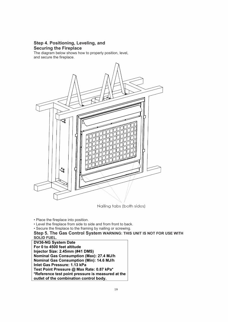
Step 4. Positioning, Leveling, and Securing the Fireplace The diagram below shows how to properly position, level, and secure the fireplace.
• Place the fireplace into position. • Level the fireplace from side to side and from front to back. • Secure the fireplace to the framing by nailing or screwing.
Step 5. The Gas Control System WARNING: THIS UNIT IS NOT FOR USE WITH
SOLID FUEL.
DV36-NG System Date For 0 to 4500 feet altitude Injector Size: 2.45mm (#41 DMS) Nominal Gas Consumption (Max): 27.4 MJ/h Nominal Gas Consumption (Min): 14.6 MJ/h Inlet Gas Pressure: 1.13 kPa Test Point Pressure @ Max Rate: 0.87 kPa* *Reference test point pressure is measured at the outlet of the combination control body.
20
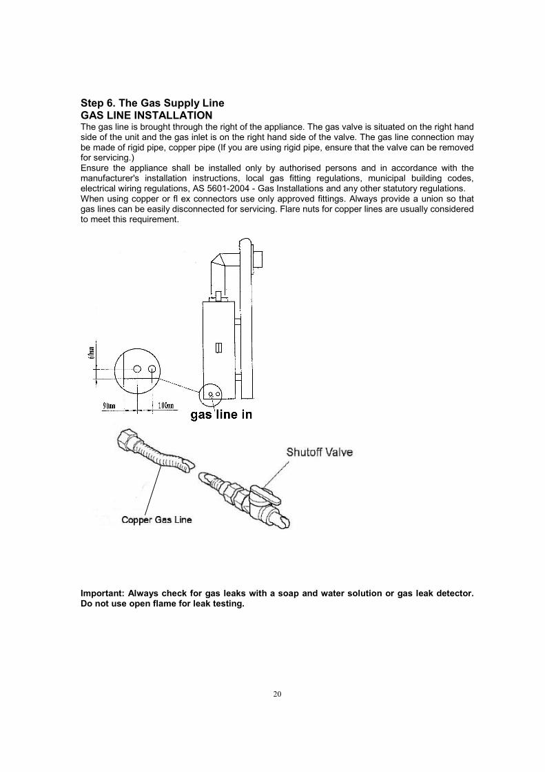
Step 6. The Gas Supply Line GAS LINE INSTALLATION The gas line is brought through the right of the appliance. The gas valve is situated on the right hand side of the unit and the gas inlet is on the right hand side of the valve. The gas line connection may be made of rigid pipe, copper pipe (If you are using rigid pipe, ensure that the valve can be removed for servicing.) Ensure the appliance shall be installed only by authorised persons and in accordance with the manufacturer's installation instructions, local gas fitting regulations, municipal building codes, electrical wiring regulations, AS 5601-2004 - Gas Installations and any other statutory regulations. When using copper or fl ex connectors use only approved fittings. Always provide a union so that gas lines can be easily disconnected for servicing. Flare nuts for copper lines are usually considered to meet this requirement.
Important: Always check for gas leaks with a soap and water solution or gas leak detector. Do not use open flame for leak testing.
21
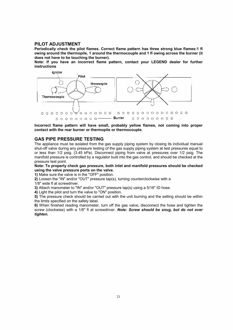
PILOT ADJUSTMENT Periodically check the pilot flames. Correct flame pattern has three strong blue flames:1 fl owing around the thermopile, 1 around the thermocouple and 1 fl owing across the burner (it does not have to be touching the burner). Note: If you have an incorrect flame pattern, contact your LEGEND dealer for further instructions
Incorrect flame pattern will have small, probably yellow flames, not coming into proper contact with the rear burner or thermopile or thermocouple.
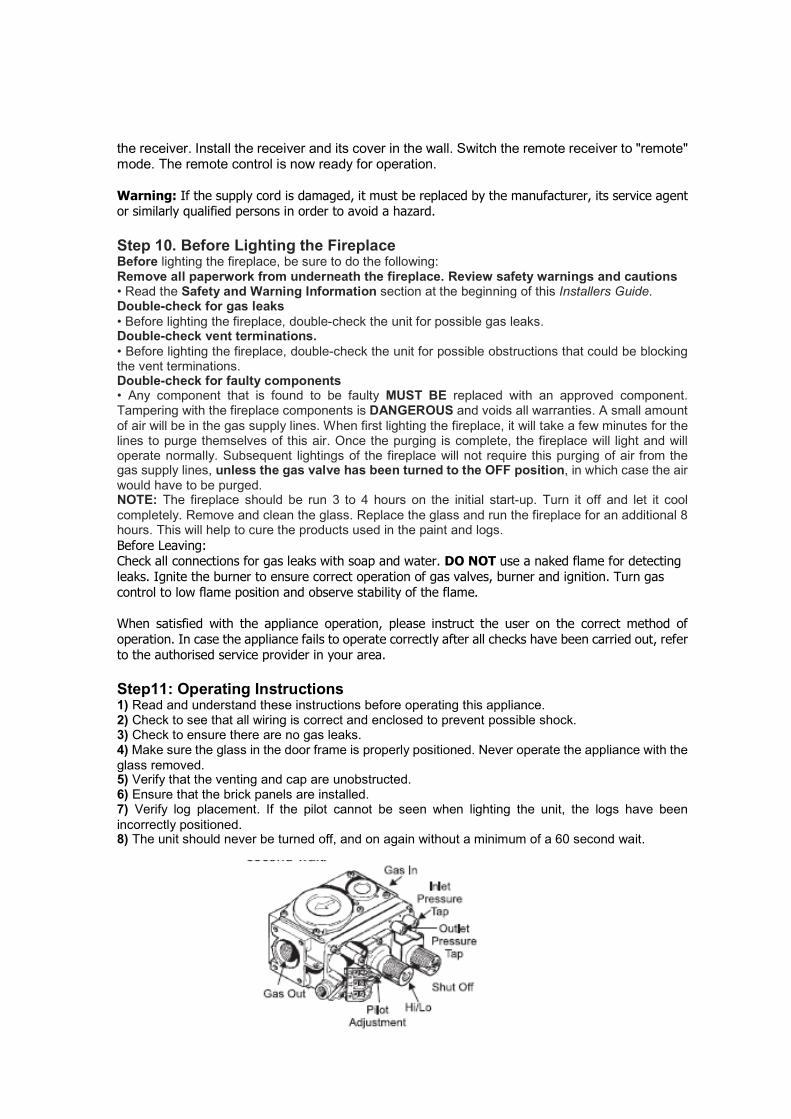
GAS PIPE PRESSURE TESTING The appliance must be isolated from the gas supply piping system by closing its individual manual shut-off valve during any pressure testing of the gas supply piping system at test pressures equal to or less than 1/2 psig. (3.45 kPa). Disconnect piping from valve at pressures over 1/2 psig. The manifold pressure is controlled by a regulator built into the gas control, and should be checked at the pressure test point. Note: To properly check gas pressure, both inlet and manifold pressures should be checked using the valve pressure ports on the valve. 1) Make sure the valve is in the "OFF" position. 2) Loosen the "IN" and/or "OUT" pressure tap(s), turning counterclockwise with a
1/8" wide fl at screwdriver. 3) Attach manometer to "IN" and/or "OUT" pressure tap(s) using a 5/16" ID hose. 4) Light the pilot and turn the valve to "ON" position. 5) The pressure check should be carried out with the unit burning and the setting should be within
the limits specified on the safety label. 6) When finished reading manometer, turn off the gas valve, disconnect the hose and tighten the
screw (clockwise) with a 1/8" fl at screwdriver. Note: Screw should be snug, but do not over tighten.

22
S.I.T. VALVE DESCRIPTION
Step 7. Gas Pressure Requirements Pressure requirements for legend gas fireplaces are shown in the table below.
Pressure
Natural Gas
Inlet Gas Pressure
1.13kPa
Manifold Pressure
0.87kPa
Caution: Ensure that the wires do not touch any hot surfaces and are away from sharp edges. NOTE: Even if the fan is not purchased with the unit, it is still a good idea to bring power to the receptacle box (not provided with the unit) in case the fan is installed at a later date.
The appliance is fitted with a power cord and 3 pin plug. Install the appliance so that the plug is easily accessible. Plug the 3-pin plug into a properly earthed, 15A general purpose power outlet. The supply cable should be positioned so that it does not reach a temperature of more than 75 degrees Celsius along its entire length. If the supply cord or plug is damaged, it must be replaced by the manufacturer or its service agent or a similarly qualified person in order to avoid hazard.
23
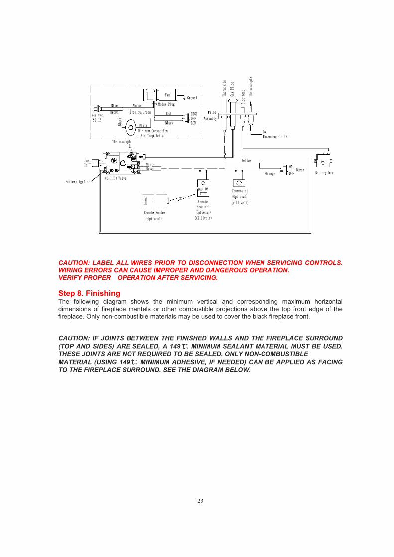
CAUTION: LABEL ALL WIRES PRIOR TO DISCONNECTION WHEN SERVICING CONTROLS. WIRING ERRORS CAN CAUSE IMPROPER AND DANGEROUS OPERATION. VERIFY PROPER OPERATION AFTER SERVICING.
Step 8. Finishing The following diagram shows the minimum vertical and corresponding maximum horizontal dimensions of fireplace mantels or other combustible projections above the top front edge of the fireplace. Only non-combustible materials may be used to cover the black fireplace front. CAUTION: IF JOINTS BETWEEN THE FINISHED WALLS AND THE FIREPLACE SURROUND
(TOP AND SIDES) ARE SEALED, A 149℃℃℃℃. MINIMUM SEALANT MATERIAL MUST BE USED.
THESE JOINTS ARE NOT REQUIRED TO BE SEALED. ONLY NON-COMBUSTIBLE
MATERIAL (USING 149℃℃℃℃. MINIMUM ADHESIVE, IF NEEDED) CAN BE APPLIED AS FACING
TO THE FIREPLACE SURROUND. SEE THE DIAGRAM BELOW.

24
Hearth Extensions
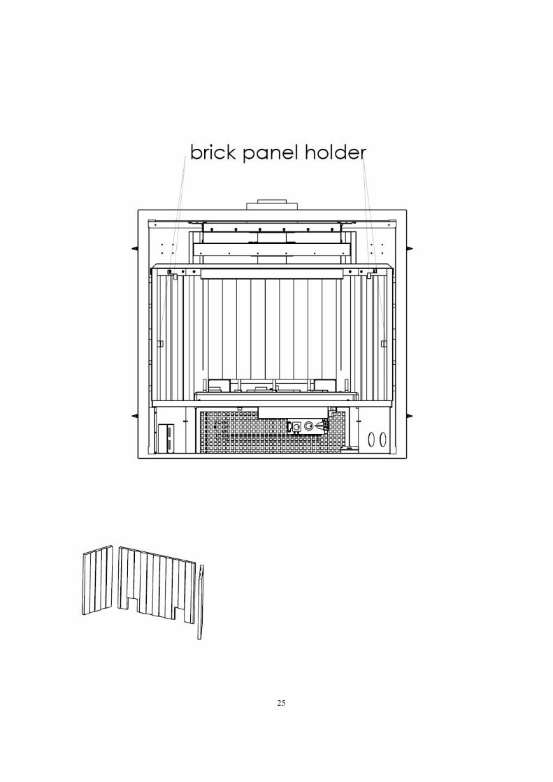
Step 9. Position brick panels, Logs, log Ember and glowing Material and remote control. Brick panels (optional panel models may be installed in different manner) 1) Undo the bottom 2 door latches and open and remove glass door. Remove logs. Note: The logs must not be in the unit. 2) Insert the back brick panel first by carefully slipping it between the back wall of the firebox and the
rear log bracket. 3) Put the side panels in next. Slide them in from the front and push them flat up against the wall. Be
very careful not to scratch them on the firebox hardware. 4) Install the 2 brick retaining clips, one on each side.
25
Positioning the Logs

26
The logs have been packed separately, refer to thefollowing pics to position the log ember, the glowing material and log set. If sooting occurs, the logs might need to be repositioned slightly to avoid excessive flame impingement. If logs are broken do not use the unit until they are replaced. Broken logs can interfere with the pilot operation. Brick Panels, install the Brick Panels prior to installing the logs. (factory finished)
1) Carefully remove the logs from the box and unwrap them.
Ceramic log set (6pcs/set) log ember and glowing material The logs are fragile, handle with care - do not force into position. 2) Place 25 grams of log ember over the burner ports as shown in the photo below.
3)Place the log set in position as shown below
4)Place the glowing material to cover the log ember on burner pan

27
NOTE: PLEASE MAKE SURE THE LOG DO NOT COVER THE HOLES ON BURNER PAN, AND MAKE SURE THE LOG SET COULD NOT OBSTRUCT THE FLAME, IF NOT, THE SOOTING WILL SOON DEPOSIT.
INSTALLATION OF STANDARD FLUSH DOOR The standard flush door comes with a black frame. To install the frame, simply hook the top door
flange onto the top of the unit and swing the door towards the unit, see the following diagram.
Be careful that the glass gasket does not roll up; there must be a gap between the gasket and the door lip to ensure that the door sits securely on the unit, see above Diagram. Insert each of the four hooks into the slots on the bottom and top of the door. To remove the flush door, reverse the above steps.
REMOTE CONTROL((((Optional)))) Use the LEGEND Remote Control Kit approved for this unit. Use of other systems may void your warranty. The remote control kit comes with a hand held transmitter, a receiver and a wall mounting plate. In factory the remote receiver are positioned in the bottom of fireplace. If you want mount it on the wall, please follow the installing procedure. 1) Choose a convenient location on the wall to install the receiver and the receptacle box (protection
from extreme heat is very important). Run wires from the fireplace to that location. Use the Thermostat Wire Table. 2) Connect the two wires to the gas valve.
CAUTION Do not connect millivolt remote control wires to 240V wire. 3) Install 1 AAA alkaline batteries AND 1 LI battery in transmitter and 4 AA alkaline batteries in
28
the receiver. Install the receiver and its cover in the wall. Switch the remote receiver to "remote" mode. The remote control is now ready for operation.
Warning: If the supply cord is damaged, it must be replaced by the manufacturer, its service agent or similarly qualified persons in order to avoid a hazard.
Step 10. Before Lighting the Fireplace Before lighting the fireplace, be sure to do the following: Remove all paperwork from underneath the fireplace. Review safety warnings and cautions • Read the Safety and Warning Information section at the beginning of this Installers Guide. Double-check for gas leaks
• Before lighting the fireplace, double-check the unit for possible gas leaks. Double-check vent terminations.
• Before lighting the fireplace, double-check the unit for possible obstructions that could be blocking the vent terminations. Double-check for faulty components • Any component that is found to be faulty MUST BE replaced with an approved component. Tampering with the fireplace components is DANGEROUS and voids all warranties. A small amount
of air will be in the gas supply lines. When first lighting the fireplace, it will take a few minutes for the lines to purge themselves of this air. Once the purging is complete, the fireplace will light and will operate normally. Subsequent lightings of the fireplace will not require this purging of air from the gas supply lines, unless the gas valve has been turned to the OFF position, in which case the air
would have to be purged. NOTE: The fireplace should be run 3 to 4 hours on the initial start-up. Turn it off and let it cool
completely. Remove and clean the glass. Replace the glass and run the fireplace for an additional 8 hours. This will help to cure the products used in the paint and logs.
Before Leaving: Check all connections for gas leaks with soap and water. DO NOT use a naked flame for detecting
leaks. Ignite the burner to ensure correct operation of gas valves, burner and ignition. Turn gas
control to low flame position and observe stability of the flame.
When satisfied with the appliance operation, please instruct the user on the correct method of
operation. In case the appliance fails to operate correctly after all checks have been carried out, refer
to the authorised service provider in your area. Step11: Operating Instructions 1) Read and understand these instructions before operating this appliance. 2) Check to see that all wiring is correct and enclosed to prevent possible shock. 3) Check to ensure there are no gas leaks. 4) Make sure the glass in the door frame is properly positioned. Never operate the appliance with the
glass removed. 5) Verify that the venting and cap are unobstructed. 6) Ensure that the brick panels are installed. 7) Verify log placement. If the pilot cannot be seen when lighting the unit, the logs have been
incorrectly positioned. 8) The unit should never be turned off, and on again without a minimum of a 60 second wait.

29
LIGHTING PROCEDURE The legend fireplace are equipped with electric spark ignitor box. Important: to ignite and reignite the pilot, you must first open the bottom louver. IMPORTANT Gas on/off knob cannot be turned from "PILOT" to "OFF" unless it is partially depressed.
NOTE: IF APPLIANCES FAILS TO IGNITE, ENSURE AA BATTERIES ARE FITTED IN THE BATTERY BOX. 1)Turn burner OFF using "ON/OFF" switch. 2) Turn gas control knob so indicator points to "OFF" position and allow 5 minutes for any gas in the
combustion chamber to escape. 3) Turn gas control knob counterclockwise so indicator points to the "PILOT" position. Push the gas
control knob all the way and hold in until the pilot lights up.. After approximately half minute, release the gas control knob. The pilot flame should continue to burn. If the pilot does not remain lit, repeat operation allowing a longer period before releasing gas control knob. 4) When the pilot stays lit, turn the gas knob further counterclockwise to the "ON" position. 5) Use the on/off switch, thermostat or remote control to turn on the unit. 6) Rotate the flame height regulator to adjust the flame height higher or lower.
SHUTDOWN PROCEDURE 1) Use the switch, thermostat or remote control to turn off the main burner. 2) Turn the main gas control clockwise to the "OFF" position to turn off the pilot.
3) Turn off all electric power to appliance if service is to be performed. DO NOT ATTEMPT TO CLEAN THE GLASS WHILE IT IS HOT. DO NOT BURN THE APPLIANCE WITHOUT THE GLASS FRONT IN PLACE
AERATION ADJUSTMENT The air shutter can be adjusted by moving the adjusting cap. The air shutter cap is connected in the gas tube under the main burner. If you want to adjust the air shutter, you must take the burner grate off and apply screw driver to adjust it. Open the air shutter for a blue flame or close for a yellower flame. The burner aeration is factory set but may need adjusting due to either the local gas supply or altitude. Minimum Air Shutter Opening:
8mm————Natural Gas
CAUTION: Carbon will be produced if air shutter is closed too much. Note: Any damage due to carboning resulting from improperly setting the aeration controls is NOT covered under warranty. Note: Aeration Adjustment should only be performed by an authorized LEGEND Installer at the time of installation or service. Closed - Tall yellow Open - Short Blue
NORMAL OPERATING SOUNDS OF GAS APPLIANCES It is possible that you will hear some sounds from your gas appliance. This is perfectly normal due to the fact that there are various gauges and types of steel used within your appliance. Listed below are some examples. All are normal operating sounds and should not be considered as defects in
your appliance. Blower: LEGEND gas appliances use high tech blowers to push heated air farther into the room. It
is not unusual for the fan to make a "whirring" sound when ON. This sound will increase or decrease in volume depending on the speed setting of your fan speed control. Blower Thermodisc: When this thermally activated switch turns ON it will create a small "clicking"
sound. This is the switch contacts closing and is normal. Pilot Flame: While the pilot flame is on it can make a very slight "whisper" sound. Gas Control Valve: As the gas control valve turns ON and OFF, a dull clicking sound may be
audible, this is normal operation of a gas regulator or valve. Unit Body/Firebox: Different types and thicknesses of steel will expand and contract at different
rates resulting in some "cracking" and "ticking" sounds will be heard throughout the cycling process.

30
THE LIGHTING PLATE INSTRUCTIONS

31
4Maintaining and Servicing Your Fireplace
Part list: Warning: Servicing shall be carried out only by authorized personnel. A set of DV36 includes the unit and the log set packed separately. 1. Standard log set includes 6 pcs of log from A to F, one for each.

32
2. fireplace body packed separately.
No Name Qty No Name Qty
1 Bottom grill 1 22 Side and back frame 1
2 Top grill 1 23 Spacer 1
3 Front frame 1 24 Air box outside guider part2 1
4 Mesh frame 1 25 Air box assembly 1
5 Glass assembly 1 26 Side standoff 8
6 Glass frame 1 27 Inner exhausting base 1
7 Glass frame hook spring 2 28 Air output guider part 1 1
8 Gas valve 1 29 Air output guider part 2 1
9 Air intake bracket 1 30 Air output guider part 3 1
10 Burner assembly 1 31 Inner exhausting tube 1
11 Battery box 1 32 Inner top heat shield 1
12 Spacer 1 33 Ceramic blanket 1
13 Switch box bracket 1 34 Outer exhausting tube 1
14 Switch box 1 35 Top standoff 3
15 Blower mesh 1 36 Pilot and bracket 1
16 Bottom of fireplace 1 37 Brick panel holder 3
17 Firebox 1 38 Burner basin assembly 1
18 Spacer 2 39 Heat insulation paper 1
19 Air box outside guider part1 1 40 Back brick panel 1
20 Blower 1 41 Side brick panel 2
21 Blower bracket 1 42 Air intake guider 1

33
CLEANING AND MAINTENANCE Make sure the gas valve knob is in the “OFF” position. Wait at least five (5) minutes before starting
maintenance. Fireplace must be cold before starting maintenance.
VENTING SYSTEM
A qualified agency should examine the venting system annually.
CLEANING GLASS
CAUTION
Let glass cool before cleaning. Do not clean glass when it is hot. Damage could occur.
Clean the tempered glass periodically. Condensation will sometimes form on the glass during a cold
startup. This is normal for all gas fireplaces. This condensation often attracts dust and lint to the surface
of the glass. The initial paint curing of the appliance can also leave a slight film on the glass. You should
clean the glass after the first two weeks of use. After that, you should clean the glass no more than two
or three times a season. Use a mild glass cleaner to clean the door. Do not use abrasive cleaners. They
will damage the glass surface.
PILOT AND BURNER FLAMES
Visually check pilot and burner flames periodically.
Firebox cleaning:
1. Carefully remove ceramic fibre logs from burner pan.
2. Vacuum burner compartment thoroughly. 3. Vacuum or brush with soft brush any dust burner pan
4. Remove any lint from main burner and pilot.
5. Carefully replace ceramic fibre logs. 6. Replace door (if it has been removed).
7. Relight pilot.
8. Turn on main burner.
WARNING
Make sure clearances to combustibles leave room for maintenance and service. Carefully
reassemble and reseal fireplace properly after any cleaning or servicing.

34
TROUBLESHOOTING STANDING PILOT IGNITION
SYMPTOM POSSIBLE CAUSE ACTION
1. Spark ignitor will not light pilot.
A. Wire disconnected. B. Defective ignitor. C. No gas or low gas pressure. D. Batteries not fitted or batteries flat.
A. Open door and check to make sure wire is connected to ignitor. B. Check for spark at electrode and pilot. If no spark and electrode wire is properly connected, replace pilot assembly. C. Check remote/manual shut off valve from fireplace. Low pressure can be caused by bent lines, restricted lines, low pressure line pressure. Consult with plumber or gas supplier. Check battery box.
2. Pilot will not stay lit after carefully following lighting instructions.
A. Defective thermocouple B. Defective valve
A. Check that thermocouple flame impinges on thermocouple. Clean and/or adjust pilot for maximum flame impingement. Ensure that the thermocouple connection at the gas valve is fully inserted and tight. Disconnect the thermocouple from the valve, place one millivolt lead wire on the tip of the thermocouple and the other meter lead wire on the thermocouple copper lead. Start the pilot and hold the valve knob in. If the millivolt reading is less than 15 mV, replace pilot assembly. B. If thermocouple is producing more than 15 mV, replace faulty valve.
3. Pilot burning, valve knob turned to “ON”, switch is turned to “ON” or “RS”, but burner will not ignite. replace pilot assembly.
A. Defective switch, wall switch, remote control or wire B. Pilot flame too small C. Defective or malfunctioning thermopile D. Defective valve
A. Check switch and wire for proper connection. Place jumper wires across terminals of switch. If burner comes on, replace defective switch.If the switch is OK, repeat the same procedure on remote control If burner comes on, replace remote control. Place jumper wire across wire at gas valves (terminals marked TH and TP/TH). If burner comes on, wires are faulty or connections are bad. Replace wire. B. If pilot flame is not close enough

35
to the thermopile, adjust pilot flame. C. Check thermopile wire connections to make sure all are tight and that the thermopile is fully inserted into pilot assembly. Check thermopile with a millivolt meter. Connect leads to TP and TP/TH terminals on the control valve. If meter reading is below 325 mV, D. Turn valve knob to “On” and switch to “ON.” Take a reading at the thermopile leads (TP & TP/TH) on the valve. If the meter reads greater than 175 mV and the burner does not light, replace defective valve.
4. Frequent pilot outage problem.
A. Pilot flame may be too high or too low, causing pilot safety to drop out
A. Clean and adjust the pilot flame for maximum flame impingement on thermocouple.
5. The pilot and main burner extinguish while in operation
A. Inner vent pipe leaking exhaust gases back into system B. Horizontal vent improperly pitched C. Improper vent cap installation
A. Check for flue product leak. Replace defective pipe section. B. Check horizontal-venting piping is running upward 1/4" per foot. Do not run the pipe level or downward. C. Check for proper installation and freedom from debris or blockage
36
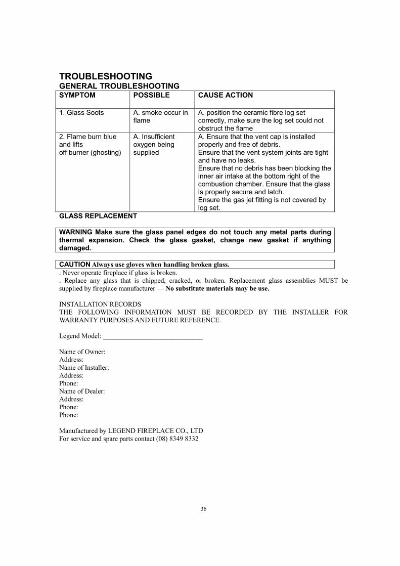
TROUBLESHOOTING GENERAL TROUBLESHOOTING SYMPTOM POSSIBLE CAUSE ACTION
1. Glass Soots A. smoke occur in
flame A. position the ceramic fibre log set correctly, make sure the log set could not obstruct the flame
2. Flame burn blue and lifts off burner (ghosting)
A. Insufficient oxygen being supplied
A. Ensure that the vent cap is installed properly and free of debris. Ensure that the vent system joints are tight and have no leaks. Ensure that no debris has been blocking the inner air intake at the bottom right of the combustion chamber. Ensure that the glass is properly secure and latch. Ensure the gas jet fitting is not covered by log set.
GLASS REPLACEMENT
WARNING Make sure the glass panel edges do not touch any metal parts during thermal expansion. Check the glass gasket, change new gasket if anything damaged.
CAUTION Always use gloves when handling broken glass.
. Never operate fireplace if glass is broken.
. Replace any glass that is chipped, cracked, or broken. Replacement glass assemblies MUST be
supplied by fireplace manufacturer — No substitute materials may be use.
INSTALLATION RECORDS
THE FOLLOWING INFORMATION MUST BE RECORDED BY THE INSTALLER FOR
WARRANTY PURPOSES AND FUTURE REFERENCE.
Legend Model: _____________________________
Name of Owner: Address:
Name of Installer:
Address: Phone:
Name of Dealer:
Address:
Phone:
Phone:
Manufactured by LEGEND FIREPLACE CO., LTD
For service and spare parts contact (08) 8349 8332
37
LIMITED LIFETIME WARRANTY POLICY LIFETIME WARRANTY
ONE YEAR WARRANTY The following components are warranted for 1 year to the original owner, subject of proof of purchase:
All component of the Direct vent gas fireplace
BASIC WARRANTY Legend warrants the components and materials in your gas appliance to be free from
manufacturing and material defects for a period of one year from date of installation. After installation, if any of the components manufactured by LEGEND in the appliance are found to be defective in
materials or workmanship, LEGEND will, at its option, replace or repair the defective components at no
charge to the original owner. LEGEND will also pay for reasonable labor costs incurred in replacing or repairing such components for a period of one year from the date of installation. Any products presented
for warranty repair must be accompanied by a dated proof of purchase.
This Limited Lifetime Warranty will be void if the appliance is not installed by a qualified installer in accordance with the installation instructions. The Limited Lifetime Warranty will also be void if the
appliance is not operated and maintained according to the operating instructions supplied with the appliance, and does not extend to (1) firebox/burner assembly damage by accident, neglect, misuse,
abuse, alteration, negligence of others, including the installation thereof by unqualified installers, (2) the
costs of removal, reinstallation or transportation of defective parts on the appliance, or (3) incidental or consequential damage. All service work must be performed by an authorized service representative.
This warranty is expressly in lieu of other warranties, express or implied, including the warranty of
merchantability of fitness for purpose and of all other obligations or liabilities. Legend does not assume
for it any other obligations or liability in connection with the sale or use of the appliance. In states that
do not allow limitations on how long an implied warranty lasts, or do not allow exclusion of indirect
damage, those limitations of exclusions may not apply to you. You may also have additional rights not
covered in this Limited Lifetime Warranty.
Legend Fireplace Co.,Ltd reserves the right to investigate any and all claims against the Limited Lifetime Warranty and decide upon method of settlement.
For information about this warranty, contact:
LEGEND FIREPLACE CO., LTD