manual on quality assurance for the survey, evaluation and
TRANSCRIPT

IAEA-TECDOC-416
MANUAL ON QUALITY ASSURANCEFOR THE
SURVEY, EVALUATION AND CONFIRMATIONOF NUCLEAR POWER PLANT SITES
A TECHNICAL DOCUMENT ISSUED BY THEINTERNATIONAL ATOMIC ENERGY AGENCY, VIENNA, 1987

MANUAL ON QUALITY ASSURANCE FOR THE SURVEY,EVALUATION AND CONFIRMATION OF NUCLEAR POWER PLANT SITES
IAEA, VIENNA, 1987IAEA-TECDOC-416
Printed by the IAEA in AustriaApril 1987

PLEASE BE AWARE THATALL OF THE MISSING PAGES IN THIS DOCUMENT
WERE ORIGINALLY BLANK

The IAEA does not normally maintain stocks of reports in this series.However, microfiche copies of these reports can be obtained from
IN IS ClearinghouseInternational Atomic Energy AgencyWagramerstrasse 5P.O. Box 100A-1400 Vienna, Austria
Orders should be accompanied by prepayment of Austrian Schillings 100,-in the form of a cheque or in the form of IAEA microfiche service couponswhich may be ordered separately from the INIS Clearinghouse.

FOREWORD
The Agency's plans for establishing safety standards for nuclearpower plants referred to as the Nuclear Safety Standards (NUSS)programme, have been set out in IAEA document GC(CXIII)526/MOD.l. Theobjective of the programme as stated in this document is to proceed withthe development of three types of documents:
(a) Codes of Practice for thermal neutron nuclear power plants, whichestablish the objectives and minimum requirements that must befulfilled to provide adequate safety for these plants;
(b) Safety Guides which provide additional requirements and recommendprocedures that should be followed to implement the Code of Practice.
(c) User's Manuals, intended primarily to nuclear power plant operators,which normally present one or several possible methods andtechniques for solving specific problems.
Work on Codes and Guides was initiated in 1975 in five main fields:governmental organization, siting, design, operation and qualityassurance.
In the field of quality assurance (QA) a Code of Practice and tenSafety Guides have been developed and published in English, French,Spanish and Russian. These publications are used in a number of MemberStates to establish quality assurance requirements for nuclear powerplants. To facilitate their use the Technical Review Committee on QualityAssurance has stressed on a number of occasions the need for UsersManuals and recommended that the Agency proceed with the development ofthese Manuals. These documents should provide Member States implementingthe Code and the Safety Guides with examples of procedures, practices anddocuments illustrating quality assurance methods and techniques used inthese organizations in Member States having broad experience in qualityassurance. The same opinion was expressed in discussions during theInternational Symposium on Quality Assurance for Nuclear Power Plants,held in Paris, in May 1981.
A number of topics were identified at the Symposium for which User'sManuals could provide additional information and facilitate correctimplementation of the Code and Guides in nuclear power plant projectactivities.
To implement these recommendations work has been initiated in theSecretariat to develop those User's Manuals which are most needed inMember States embarking on nuclear power programme and initiating qualityassurance activities. In view of the difference between User's manualsand Codes and Safety Guides, work on User's Manuals is undertaken outsidethe NUSS programmes established procedures for development, review andapproval of the documents. For User's Manuals it was decided to followthe standard practices used in the development of Agency publicationssuch as Guidebooks and Technical Reports. This procedure is expected toreduce the time and cost of preparation of User's Manuals, which are atthe lowest level in the hierarchy of NUSS programme documents and do notcontain requirements for which formulation a broad consensus of QAexperts would be needed.
The full consistency of the User's Manuals with the Code and SafetyGuides is ensured by information exchange between the Secretariat andmembers of the Technical Review Committee on Quality Assurance and theSenior Advisory Group of the NUSS programme. Also, members of the lattertwo groups, in the capacity of consultants to the Agency and members ofadvisory groups, are engaged in the development, review and approval ofUser's Manuals before these are recommended to the Director General forpublication.
The present Manual on Quality Assurance for the Survey, Evaluationand Confirmation of Nuclear Power Plant Sites contains supportingmaterial and illustrates examples for implementing the requirementscontained in the Code of Practice on Quality Assurance for Safety inNuclear Power Plants (IAEA Safety Series No. 50-C-QA, 1978) to theactivities of survey, evaluation and confirmation of nuclear power plantsites.
At the same time the Code of Practice for Safety in Nuclear PowerPlant Siting (IAEA Safety Series No. 50-C-S, 1978), and Safety Guides inthe siting series contain requirements and recommendations to implement aquality assurance programme in selected activities of the siting process.

This manual is intended to provide guidance and illustrate examples onthis implementation.
During preparation and reviews of this Manual it was found out thatthe methodology of implementation of the quality assurance programme insiting activities is still under development. For these reasons it wasconsidered appropriate to publish this Manual as a temporary publicationfor trial use. It is the intention of the Secretariat to collectinformation from the use of this document in nuclear power projectactivities and prepare a revision as soon as the relevant methods andtechniques obtain a broader support from quality assurance organizationsin nuclear power projects.

EDITORIAL NOTE
In preparing this material for the press, staff of the International Atomic Energy Agencyhave mounted and paginated the original manuscripts and given some attention to presentation.
The riews expressed do not necessarily reflect those of t/ie governments of the Member Statesor organizations under whose auspices the manuscripts were produced.
The use in this book of particular designations of countries or territories does not imply anyjudgement by the publisher, the IAEA, as to the legal status of such countries or territories, oftheir authorities and institutions or of the delimitation of their boundaries.
The mention of specific companies or of their products or brand names does not imply anyendorsement or recommendation on the part of the IAEA.

CONTENTS
1. INTRODUCTION.. . . . . . . . . . . . . . . . . . . . . . . . . . . . . . . . . . . . . . . . . . . . . . . . . . . . . . . . . . . . . . . . . . . . . . . . . . . . . . . . . . . . . . 11
1.1. General. . . . . . . . . . . . . . . . . . . . . . . . . . . . . . . . . . . . . . . . . . . . . . . . . . . . . . . . . . . . . . . . . . . . . . . . . . . . . . . . . . . . . . . . . . . . . . 111.2. Quality Assurance Programme... . . . . . . . . . . . . . . . . . . . . . . . . . . . . . . . . . . . . . . . . . . . . . . . . . . . . . . . . . . . . . . . 131.3. Responsibi l i ty . . . . . . . . . . . . . . . . . . . . . . . . . . . . . . . . . . . . . . . . . . . . . . . . . . . . . . . . . . . . . . . . . . . . . . . . . . . . . . . . . . . . . . 13
2. QA PROGRAMME ESTABLISHMENT........................................................... 14
2.1. General . . . . . . . . . . . . . . . . . . . . . . . . . . . . . . . . . . . . . . . . . . . . . . . . . . . . . . . . . . . . . . . . . . . . . . . . . . . . . . . . . . . . . . . . . . . . . . 142.2. Classification of Services... . . . . . . . . . . . . . . . . . . . . . . . . . . . . . . . . . . . . . . . . . . . . . . . . . . . . . . . . . . . . . . . . . . . . . 142.3. Quality Assurance Activit ies. . . . . . . . . . . . . . . . . . . . . . . . . . . . . . . . . . . . . . . . . . . . . . . . . . . . . . . . . . . . . . . . . . . . 152.4. Grading of the QA Activi t ies . . . . . . . . . . . . . . . . . . . . . . . . . . . . . . . . . . . . . . . . . . . . . . . . . . . . . . . . . . . . . . . . . . . 152.5. Constituent QA Programmes, Quality Assurance for Specialty Services...... ........ 17
3. QA PROGRAMME COVERAGE (SCOPE). . . . . . . . . . . . . . . . . . . . . . . . . . . . . . . . . . . . . . . . . . . . . . . . . . . . . . . 18
3.1. Review of Siting Activi t ies . . . . . . . . . . . . . . . . . . . . . . . . . . . . . . . . . . . . . . . . . . . . . . . . . . . . . . . . . . . . . . . . . . . . . . 183.2. Classification of Siting Activities....... . . . . . . . . . . . . . . . . . . . . . . . . . . . . . . . . . . . . . . . . . . . . . . . . . . . . . . . 183.3. Grading of the QA Activities for Siting.. . . . . . . . . . . . . . . . . . . . . . . . . . . . . . . . . . . . . . . . . . . . . . . . . . . . . 19
4. QA PROGRAMME DOCUMENTATION.. . . . . . . . . . . . . . . . . . . . . . . . . . . . . . . . . . . . . . . . . . . . . . . . . . . . . . . . 31
4.1. General . . . . . . . . . . . . . . . . . . . . . . . . . . . . . . . . . . . . . . . . . . . . . . . . . . . . . . . . . . . . . . . . . . . . . . . . . . . . . . . . . . . . . . . . . . . . . . 314.2. QA Programme Description..................................................................... 314.3. QA Programme Procedures..................................................................... 324.4. Work Plans and Schedules...................................................................... 344.5. Work Procedures and Instructions.. . . . . . . . . . . . . . . . . . . . . . . . . . . . . . . . . . . . . . . . . . . . . . . . . . . . . . . . . . . . 344.6. Manuals. . . . . . . . . . . . . . . . . . . . . . . . . . . . . . . . . . . . . . . . . . . . . . . . . . . . . . . . . . . . . . . . . . . . . . . . . . . . . . . . . . . . . . . . . . . . . 36
4.6.1. Project Management Procedures Manual. . . . . . . . . . . . . . . . . . . . . . . . . . . . . . . . . . . . . . . . . . . . 374.6.2. Technical Disciplines Procedures Manual. . . . . . . . . . . . . . . . . . . . . . . . . . . . . . . . . . . . . . . . . . . 374.6.3. QA Manual. . . . . . . . . . . . . . . . . . . . . . . . . . . . . . . . . . . . . . . . . . . . . . . . . . . . . . . . . . . . . . . . . . . . . . . . . . . . . . . . 38
5. ORGANIZATION.. . . . . . . . . . . . . . . . . . . . . . . . . . . . . . . . . . . . . . . . . . . . . . . . . . . . . . . . . . . . . . . . . . . . . . . . . . . . . . . . . . . . . . 39
5.1. General . . . . . . . . . . . . . . . . . . . . . . . . . . . . . . . . . . . . . . . . . . . . . . . . . . . . . . . . . . . . . . . . . . . . . . . . . . . . . . . . . . . . . . . . . . . . . . 395.2. Staffing of Personnel. . . . . . . . . . . . . . . . . . . . . . . . . . . . . . . . . . . . . . . . . . . . . . . . . . . . . . . . . . . . . . . . . . . . . . . . . . . . . 39
5.2.1. Functions and Responsibilities......................................................... 405.3. Qualifications and Training of Personnel . . . . . . . . . . . . . . . . . . . . . . . . . . . . . . . . . . . . . . . . . . . . . . . . . . . . . 425.4. Quality Assurance Training of Consultant's Personnel.................................... 435.5. Siting Review Committee. . . . . . . . . . . . . . . . . . . . . . . . . . . . . . . . . . . . . . . . . . . . . . . . . . . . . . . . . . . . . . . . . . . . . . . . 44
6. QA PROGRAMME IMPLEMENTATION... . . . . . . . . . . . . . . . . . . . . . . . . . . . . . . . . . . . . . . . . . . . . . . . . . . . . . . 45
6.1. General. . . . . . . . . . . . . . . . . . . . . . . . . . . . . . . . . . . . . . . . . . . . . . . . . . . . . . . . . . . . . . . . . . . . . . . . . . . . . . . . . . . . . . . . . . . . . . 456.2. Document Control................................................................................. 456.3. Control of Studies, Evaluations and Analyses.. . . . . . . . . . . . . . . . . . . . . . . . . . . . . . . . . . . . . . . . . . . . . . 466.4. Procurement Control. . . . . . . . . . . . . . . . . . . . . . . . . . . . . . . . . . . . . . . . . . . . . . . . . . . . . . . . . . . . . . . . . . . . . . . . . . . . . . 47
6.4.1. General . . . . . . . . . . . . . . . . . . . . . . . . . . . . . . . . . . . . . . . . . . . . . . . . . . . . . . . . . . . . . . . . . . . . . . . . . . . . . . . . . . . . . 47

6.4.2. Procurement Document Preparation and Control. . . . . . . . . . . . . . . . . . . . . . . . . . . . . . . . . . 486.4.3. Selection of Suppliers of Services and Equipment... . . . . . . . . . . . . . . . . . . . . . . . . . . . . . . 496.4.4. Bid Evaluation and Award of Contract. . . . . . . . . . . . . . . . . . . . . . . . . . . . . . . . . . . . . . . . . . . . . . 496.4.5. Control of Suppliers Performance.. . . . . . . . . . . . . . . . . . . . . . . . . . . . . . . . . . . . . . . . . . . . . . . . . . . 496.4.6. Acceptance of Services or Equipment. . . . . . . . . . . . . . . . . . . . . . . . . . . . . . . . . . . . . . . . . . . . . . . 50
6.5. Material Control . . . . . . . . . . . . . . . . . . . . . . . . . . . . . . . . . . . . . . . . . . . . . . . . . . . . . . . . . . . . . . . . . . . . . . . . . . . . . . . . . . . 516.5.1. General. . . . . . . . . . . . . . . . . . . . . . . . . . . . . . . . . . . . . . . . . . . . . . . . . . . . . . . . . . . . . . . . . . . . . . . . . . . . . . . . . . . . . 516.5.2. Handling, Shipping and Storage of Samples........................................ 51
6.6. Process Control... . . . . . . . . . . . . . . . . . . . . . . . . . . . . . . . . . . . . . . . . . . . . . . . . . . . . . . . . . . . . . . . . . . . . . . . . . . . . . . . . . 526.7. Quality Verifications.. . . . . . . . . . . . . . . . . . . . . . . . . . . . . . . . . . . . . . . . . . . . . . . . . . . . . . . . . . . . . . . . . . . . . . . . . . . . . 52
6.7.1. Reviews of Studies, Evaluations and Analyses. . . . . . . . . . . . . . . . . . . . . . . . . . . . . . . . . . . . . 526.7.2. Field Activities Verification.. . . . . . . . . . . . . . . . . . . . . . . . . . . . . . . . . . . . . . . . . . . . . . . . . . . . . . . . . . . 536.7.3. Laboratory Activities Verification. . . . . . . . . . . . . . . . . . . . . . . . . . . . . . . . . . . . . . . . . . . . . . . . . . . . 536.7.4. Verification of Calculations and Computer Software............................. 546.7.5. Review and Evaluation of the Work by the Siting Review Committee....... 556.7.6. Calibration and Control of Measuring and Test Equipment..................... 56
6.8. Non-Conformance Control . . . . . . . . . . . . . . . . . . . . . . . . . . . . . . . . . . . . . . . . . . . . . . . . . . . . . . . . . . . . . . . . . . . . . . 576.9. Corrective Action. . . . . . . . . . . . . . . . . . . . . . . . . . . . . . . . . . . . . . . . . . . . . . . . . . . . . . . . . . . . . . . . . . . . . . . . . . . . . . . . . 576.10.Records. . . . . . . . . . . . . . . . . . . . . . . . . . . . . . . . . . . . . . . . . . . . . . . . . . . . . . . . . . . . . . . . . . . . . . . . . . . . . . . . . . . . . . . . . . . . . . 586. l l .Audits. . . . . . . . . . . . . . . . . . . . . . . . . . . . . . . . . . . . . . . . . . . . . . . . . . . . . . . . . . . . . . . . . . . . . . . . . . . . . . . . . . . . . . . . . . . . . . . . 59
ANNEX I: EXAMPLES OF DOCUMENTS USED IN THE SCOPE OF THEQA PROGRAMME FOR THE SURVEY, EVALUATION ANDCONFIRMATION OF NUCLEAR POWER PLANT SITES... . . . . . . . . . . . . . . . . . . 61
Exhibit 1. Example of Work Plant Format (4.4). . . . . . . . . . . . . . . . . . . . . . . . . . . . . . . . . . . . . . . . . . . . . . . . . . 63Exhibit 2. Example of Work Instruction Form (4.5). . . . . . . . . . . . . . . . . . . . . . . . . . . . . . . . . . . . . . . . . . . . . . 66Exhibit 3. Typical QA Activities to be Covered by the QA Programme Procedures (4.6.3) 68Exhibit 4. Example of a Typical QA Procedure (4.6.3; 6.2). . . . . . . . . . . . . . . . . . . . . . . . . . . . . . . . . . . 71Exhibit 5. Example of the Organizational Structure of a Responsible Organization
Performing Siting Activities (5.1) . . . . . . . . . . . . . . . . . . . . . . . . . . . . . . . . . . . . . . . . . . . . . . . . . . . . . . . 76Exhibit 6. Example of Position Description Form (5.2). . . . . . . . . . . . . . . . . . . . . . . . . . . . . . . . . . . . . . . . . . 77Exhibit 7. Example of Employee Experience Record (5.3) . . . . . . . . . . . . . . . . . . . . . . . . . . . . . . . . . . . . . . 78Exhibit 8. Examples of Training Requirements and Records (5.3). . . . . . . . . . . . . . . . . . . . . . . . . . . . 81Exhibit 9a. Example of the Review Committee Meeting Notice Form (5.5; 6.7.5)......... 84Exhibit 9b. Example of Review Committee Report Form (6.7.5). . . . . . . . . . . . . . . . . . . . . . . . . . . . . . . 88Exhibit 10. Example of Sample Shipment Form (6.5 .1) . . . . . . . . . . . . . . . . . . . . . . . . . . . . . . . . . . . . . . . . . . . 90Exhibit 11. Example of Sample Receipt Form (6.5.1) . . . . . . . . . . . . . . . . . . . . . . . . . . . . . . . . . . . . . . . . . . . . . 91Exhibit 12. Example of Document Review Form (6.7.1) . . . . . . . . . . . . . . . . . . . . . . . . . . . . . . . . . . . . . . . . . 92Exhibit 13. Example of Non-Conformance Reporting Form (6.8)... . . . . . . . . . . . . . . . . . . . . . . . . . . . . 93
ANNEX II: EXAMPLES OF PROCEDURES OR WORK INSTRUCTIONSFOR VARIOUS SITING ACTIVITIES.. . . . . . . . . . . . . . . . . . . . . . . . . . . . . . . . . . . . . . . . . . . . . . . 95
Exhibit 1. Example of Work Procedure for Specific Activity (4.5)Procedure for Evaluation of Design Basis Tsunami. . . . . . . . . . . . . . . . . . . . . . . . . . . . . . . . . 97
Exhibit 2. Example of Work Procedure for Specific Activity (4.5)Field Determinations of Water Levels in Observation Wells and Piezometers. 99
Exhibit 3. Example of Procedure for Preparation and Review of Computation (6.7.4).... 105Exhibit 4. Example of Procedure for Calibration and Maintenance of Measuring
and Test Equipment (6.7.6). . . . . . . . . . . . . . . . . . . . . . . . . . . . . . . . . . . . . . . . . . . . . . . . . . . . . . . . . . . . . . 108

Exhibit 5. Example of Labels to be Placed on Measuring and Test Equipment (6.7.6)... 110
ANNEX III: EXAMPLE OF DESCRIPTION OF QA ACTIVITIESFOR NUCLEAR POWER PLANT SITING IN FRANCE.. . . . . . . . . . . . . . . . . . . . . . . 113
List of Par t ic ipants . . . . . . . . . . . . . . . . . . . . . . . . . . . . . . . . . . . . . . . . . . . . . . . . . . . . . . . . . . . . . . . . . . . . . . . . . . . . . . . . . . . . . . . . . . . . . 131

1. INTRODUCTION
1.1 General
The purpose of the Quality Assurance (QA) Programme during sitingactivities for nuclear power plants is to establish a basis for thecontrol and verification of all activities affecting quality of theresults of survey, evaluation and confirmation of nuclear power plantsites and to ensure that the required quality of these results, isachieved. The performance of these activities by qualified personnel inaccordance with defined and documented procedures and work instructions,and the verification of obtained results is essential to the ultimatesuccess of the nuclear power plant project.
The process of establishing site-related parameters involvesscientific and engineering analyses and judgement. It requires besidestechnical knowledge, professional experience and judgement in makingevaluations and arriving at conclusions. In many cases the parametersobtained in this process may not lend themselves to direct verificationsthrough inspections and tests or by using other techniques which can beprecisely identified and controlled. It is of the utmost importance thatthe data on which such judgements are based be as complete and reliableas possible. It is, therefore, necessary that all activities whichprovide the data for such evaluations be performed in a systematic andcontrolled manner by technically qualified and experienced personnel.This can be achieved by establishing and implementing of a documented QAprogramme for siting activities based on QA requirements. The scope ofthe QA programme will include activities affecting safety of nuclearpower plant. The programme will consist among others of a set of the workplans and procedures that provide a detailed description of the scope ofthe work, the work schedule, verification points, data requirements,review and approval requirements, and personnel responsibilities.
The International Atomic Energy Agency (IAEA) in the scope of itsprogramme of development of nuclear safety standards in the QA area (NUSSProgramme), did not develop a Safety Guide specifically addressingquality assurance activities during the siting process. However, thegeneral principles of QA developed and presented in the Code of Practice
11

on QA for Safety in Nuclear Power Plants (IAEA Safety Series No. 50-C-QA,1978) here and after referred to as the Code should be applied also inthe siting activities. In particular, it is considered that the Codeshould be applied to the selected activities in the following stages ofthe siting process:
Site survey, which has the purpose of identifying one or more sitesthat are likely to be suitable for detailed characterization duringthe site evaluation phase. Both safety and non-safetyconsiderations should be evaluated. Site survey activities aregenerally limited to the collection, compilation, and analysis ofavailable data in the region of interest. The site survey involvesthe study and investigation of a large region. It results in asystematic screening of the region, documentation of reasons forrejection of unacceptable areas, and in selection and comparison ofthose sites that are located in the remaining acceptable areas.
Site evaluation, which includes studies and investigation of one ormore preferable sites to demonstrate that they are acceptable fromvarious aspects, in particular from the safety point of view. Siteevaluation activities include: the field and laboratoryinvestigations and the monitoring required to provide theinformation to support the design of the facility and to address thevarious regulatory requirements. Site evaluation investigationsresult in the preparation of the documents to be submitted insupport of an application for the respective permit or license.
Site confirmation, which includes those activities performed duringconstruction (pre-operational stage) and operation of the facility.These activities include (i) further investigations necessary toresolve questions which arise during the construction and operationof the facility and (ii) the continuation of monitoring programmes.Results of site confirmation investigations and monitoring areincorporated into the documents to be submitted in support ofapplication for the operation license and subsequent periodicmonitoring reports.
12
1.2 Quality Assurance Programme
The QA programme should be established for siting activities. Inprinciple, this programme represents a constituent part of the overall QAprogramme for the nuclear power project. However, considering that sitingactivities are initiated normally long before initiation of the nuclearpower project, the QA programme should be established at the earliestpossible time consistent with siting activities and should be organizedon the similar principles as the overall QA programme for nuclear powerproject. This programme should encompass the constituent QA programmesdeveloped for specific stages of the siting process and/or for specificactivities. The constituent programmes when implemented by suppliers ofequipment and services should be the contractual responsibility of therespective suppliers. These suppliers should have their constituent QAprogramme approved by the respective purchaser when required by theprocurement document. The QA programmes should be documented in variousprogramme documents including: QA programme description, programmeprocedures, work plans and schedules, work procedures and instructions.
1.3 Responsibility
The organization having overall responsibility for the nuclear powerplant project (hereinafter referred to as the "Responsible Organization")is also responsible for the establishment and implementation of aneffective overall QA programme for the plant. This includes theresponsibility for the QA programme for siting activities. Thisorganization may delegate to other organizations the work of establishingand implementing all or part of the QA programme, but it retainsresponsibility for the effectiveness of the overall programme withoutprejudice to the suppliers other obligations and legal responsibilities.Thus, the organizations supplying services in the scope of sitingactivities should have contractual obligation to establish and implementtheir constitutent QA programmes according to the specifications invokedby the contract.
13
2. QA PROGRAMME ESTABLISHMENT
2.1. General
The Code, section 1.2, provides the requirement that, "items,services and processes to which the quality assurance programmes willapply shall be identified. Appropriate methods or levels of control andverification shall be assigned to those items, services and processes.All programmes shall provide control and verification over activitiesaffecting the quality of the identified items to an extent consistentwith their importance to safety".
This requirement is further elaborated in the IAEA Safety Guide on"Establishing the Quality Assurance Programme for a Nuclear Power PlantProject", (IAEA, Safety Series No. 50-SG-QA1, 1984) hereinafter referedas 50-SG-QA1. This Guide provides additional requirements and specificrecommendations on the selection and application of appropriate qualityassurance activities to items and services to implement the requirementsof the Code.
Consistent with such requirements and recommendations, IAEA Manualon the Selection of Appropriate QA Programme for Items and Services for aNuclear Power Plant (IAEA-TECDOC-303, 1984) provides methodology andillustrative examples of the selection of appropriate QA programmes foritems and services in a nuclear power plant. The guidelines given in thepresent Manual for the classification of services and for the grading ofQA activities, related to siting, are based on this methodology.
2.2. Classification of Services
All services and associated equipment and materials hereinafterreferred to as "services" related to site survey, evaluation andconfirmation stages should be reviewed to determine which of theseservices should be subject to the QA programme and further which are inneed of more stringent controls than others. For the purpose of thisdocument, service refers to activities performed in a specific technicaldiscipline during a given stage of the siting process. In the process ofdetermining the extent of control for a particular service it is usuallyadvantageous to classify them into categories.
14

The most important factor to consider in classifying services shouldbe the effect on safety of an error or deficiency in the performance of aservice. In addition, other factors for consideration include: a) thecomplexity, uniqueness or novelty of the service; b) the need for specialcontrols, administrative methods, surveillance and inspection ofprocesses, methods and equipment related to service; c) the degree towhich functional compliance of results can be demonstrated byverifications; and d) the quality history and degree of standardizationof the service.
Criteria and specific recommendations for the classification ofservices in the various stages of the siting process are presented inSection 3 of this manual.
2.3. Quality Assurance Activities
The quality assurance activities for each service consist of twobasic types. These are characterized as programmatic activities andwork-oriented activities.
The quality assurance programmatic activities encompass theactivities of an administrative or management nature that are necessaryfor ensuring that an appropriate quality assurance programme isestablished and effectively executed. This provides a confidence thatthe activities covered by the programme are well under control. Includedare activities associated with the establishment of the programme and itsmanagement and the control of quality-affecting work activities duringsite survey, evaluation and confirmation.
The quality assurance work-oriented activities are technical innature and are normally covered by (a) the procedures and instructionsfor carrying out the work (e.g. drilling and sampling procedures) and (b)the procedures for verification of the quality of the work (e.g.inpection or test procedures).
2.4. Grading of the QA Activities
The quality assurance activities, both programmatic andwork-oriented, can be graded with respect to the scope of the applicable
15

quality assurance activities and of the degree of control andverification efforts that should be applied.
With respect to the scope of the quality assurance activity one mayselect and implement all or part of the requirements specified in theCode for that particular activity. For some services all of theapplicable requirements of the Code might be appropriate, for others onlya part of the applicable requirements may be necessary.
With respect to the degree of control and verification, factors tobe varied may include:
- extent and form of procedures and instructionsmethods of verification (inspection, testing, surveillance andaudits)extent of verification (single or redundant verification methods)
- need for and extent of audits- amount and content of records.
In principle, it may be possible to reduce the amount of control andverification activities for example when:
- Activities are well established and it may not be necessary toprepare a step-by-step procedure for performing theseactivities. (However work plans and schedules, as well asdefinition of the scope of the work for each activity, shouldalways be necessary).In these cases verification may be performed only at the finalacceptance of the work, according to established procedures.
Services considered within the scope of the QA programme should besubject to the selected QA requirements of the Code or of specificnational QA standards. For each specific service the appropriate QArequirements to be applied should be identified.
For further information on the grading of QA programme activitiesrefer to section 3.3.
16

2.5 Constituent QA Programmes, Quality Assurance for SpecialtyServices
Quality assurance for specialty services can be provided by one oftwo methods: (1) the organization supplying the speciality services maybe required to have a quality assurance programme approved by thepurchaser (e.g. the responsible organization), which should cover allaspects of their required services or (2) the organization supplying thespecialty services may be requested to implement the quality assuranceprogramme of the purchaser. In the latter case, the purchaser shouldprovide a qualified representative to monitor the work. The organizationsupplying specialty services should be required to implement proceduresestablished by the purchaser and to generate QA records as an objectiveevidence of quality of the performed work. The foregoing applies tospecialty services such as: topographic surveying; drilling and sampling;surface geophysics; borehole geophysics; laboratory testing of soil, rockand water; field testing of soil, rock or water; field monitoring ofsoil, rock, slopes, surface water, ground water, precipitation or wind;other services specific to siting.
17

3. QA PROGRAMME COVERAGE (SCOPE)
3.1. Review of Siting Activities
The QA programme for siting and site investigations should beestablished and implemented in all three stages of the siting process.
The stages are identified as follows:1. Site survey (SS)2. Site evaluation (SE)3. Site confirmation (SC)
Definitions regarding these three stages are given in Section 1 ofthis Manual.
In order to establish the appropriate QA effort for the variousservices, the technical disciplines and the types of activities involvedin the respective siting stages should be identified.
The technical disciplines related to site investigation are welldefined in terms of the disciplines necessary for the performance ofstudies recommended in the IAEA Safety Guides in the Siting Series.
The type of activities involved in siting are varied and maymanifest a significant difference from other aspects of nuclear powerplant projects.
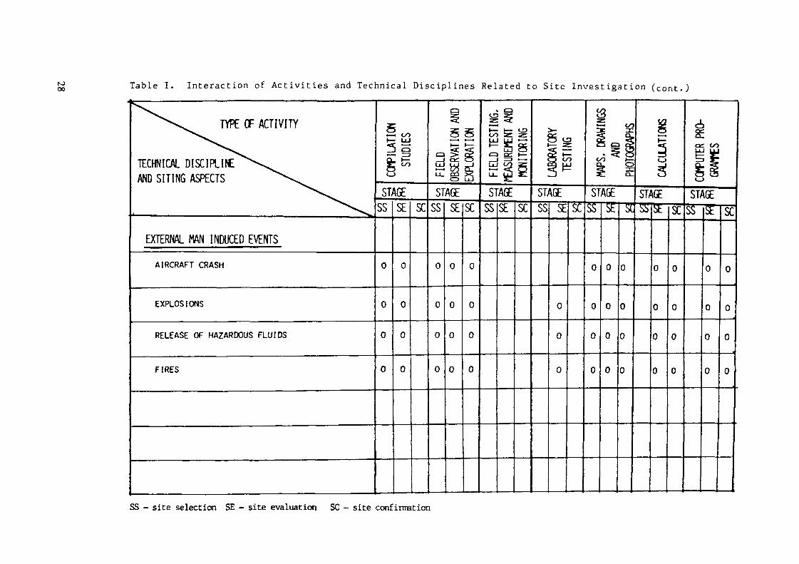
A matrix illustrating typical technical disciplines and sitingaspects along with the associated type of activities relevant to allthree stages of the siting process is given in Table I. A breakdown ofthe type of activities providing examples of typical task, performed underthe various activities is given in Table II.
3.2 Classification of Siting Services
The safety related services involved in siting should be classifiedin terms of their safety relevance and of the other factors as outlinedin Section 2.2. Tables I and II may be used as a basis for identification
18

and classification of services and subsequent establishment of anappropriate quality assurance programme.
The check-marks within the Matrix indicate the applicability of thetype of activity to the technical disciplines during respective stage ofthe siting process. They, therefore, indicate the possibility ofexistance of a related service.
3.3. Grading of the QA Activities for Siting
The selection of the proper QA effort to be adopted for the varioussiting activities should be performed in accordance with theclassification of the relevant services as outlined in Section 3.2, withthe guidelines on grading specified in Section 2.4 and considering thefollowing specific aspects, of such activities relevant to the differentsiting stages.
a) Site Survey StageIt is important that all screening data, which will or might benecessary in the subsequent siting stages for safety purposes,be subject to the equivalent QA measures specified in Section3.3.b. In selecting these measures it may not be necessary thateach of the activities performed during this stage be subjectto all of the associated QA requirements listed in the Code.However, an equivalent degree of QA efforts should be appliedfor the development of data used for comparisons of differentsites. In the site survey stage as a minimum the following QAactivities should be implemented:
planning and documenting of the activities to be performeduse of properly qualified personnelestablishment and implementation of a record system inaccordance with the Code requirements.
b) Site Evaluation StageFor the activities important to safety in this stage all theapplicable QA requirements of the Code are considered to benecessary. These requirements, properly graded, should beapplied to all those investigations and analyses performed inthis stage, that provide a direct or indirect input, in form of
19

data and analysis, into the design and licensing of plantsystems, which are safety related and whose malfunction canhave an adverse effect on radiological health and protection ofthe public and plant personnel.
c) Site Confirmation Stage
The QA effort for the activities performed during this stageshould be determined in conformance with the recommendationsspecified in Section 2.3.b, and should ensure, also, a properconsistency with QA efforts throughout the previous sitingstages.
NOTES related to Table 1
1. Symbols: SS - Site Survey; SE - Site Evaluation;SC - Site Construction.
2. The environmental aspects of siting investigation are not within thescope of this table. It is recognized that environmental aspects arean important consideration in nuclear power plant sitinginvestigations and should be a part of a total investigation program.
3. This table is intended to provide guidance as to the types ofconsiderations to be covered during siting investigations. THISTABLE IS NOT ALL INCLUSIVE.
4. Interpretation, judgement, and reporting should be considered asroutine tasks performed during assessment of indicated technicaldisciplines and siting aspects.
5. The "0" marks within the matrix indicate when services may beperformed. These services should be classified in respect of safetyand other considerations in accordance with IAEA Manual On theSelection of Appropriate QA Programme for Items and Services for aNuclear Power Plant (IAEA-TECDOC-303, 1984).
20

Table I. Interaction of Activities and Technical Disciplines Related to Site Investigation
TYPE OF ACTIVITY
TECHNICAL DISCIPLINEAND SITING ASPECTS
c/o
STAGESS SE X
STAGESS SE SC
Lu! CO S
STAGESS SE SC
oo
STAGESS SE SC
oo
STAGE STAGE STAGES^ISEl SC SS SE i SC
DEMOGRAPHY
- POPULATION DISTRIBUTION
- EMERGENCY PLANNING
SS - site selection SE - site evaluation SC - site confirmation

10N) Table I. Interaction of Activities and Technical Disciplines Related to Site Investigation (cont.)
TYPE OF ACTIVITY
TECHNICAL DISCIPLINEAND SITING ASPECTS
STAGESS SE SC
cd
STAGESS SE SC
STAGESS SE SC
ioo
STAGESS SE SC
STAGE STAGE
co
STAGE
ŒTEOROLOGY
DISPERSION
EXTREME EVENTS
SS - site selection SE - site evaluation SC - site confirmation
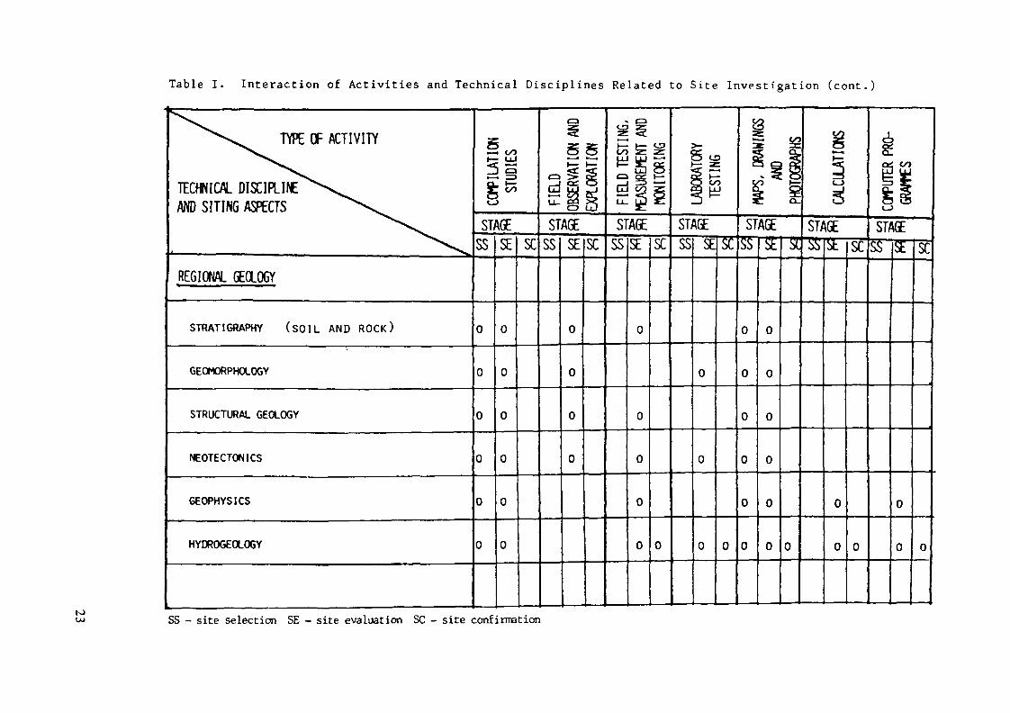
Table I. Interaction of Activities and Technical Disciplines Related to Site Investigation (cont.)
to
TYPE OF ACTIVITY
TECHNICAL DISCIPLIf£AND SITING ASPECTS
REGIONAL GEOLOGY
STRATIGRAPHY (SOIL AND ROCK)
GEOMORPHOLOGY
STRUCTURAL GEOLOGY
NEOTECTON1CS
GEOPHYSICS
HYDROGEOLOGY
.=. cofe Ui—) e
STAGESS SE SC
STAGESS SE SC
Si
STAGESSSE SC
O CD
OO
STAGESS SESC
I ï
STAGEs i si aSTAGE
SS - site selection SE - site evaluation SC - site confirmation
STAGE'SS SEIsc

to Table I. Interaction of Activities and Technical Disciplines Related to Site Investigation (cor.t.1)
TECHNICAL DISCIPLINEAND SITING ASPECTS
SITF GEQLSTRATIGRAPHY (SOIL AND R O C K )
GEOMORPHOLOGY
STRUCTURAL GEOLOGY
NEOTECTONICS
GEOPHYSICS
GEOCHEMISTRY____________SOIL AND ROCK MECHANICS
TOPOGRAPHY
BATHYMETRYHYDKOGEOLOGY
STAGESS SE SC
o l a
CE:
STAGESS SESC
sQj
STAGESS SE SC
o
n
25CO
STAGESS SE
n l n
STAGE
o o
STAGE
SS - site sélection SE - site évaluation SC - site confirnation
STAGESS <£|SC
Û-.JLJ

Table I. Interaction of Activities and Technical Disciplines Related to Site Investigation (cont.)
TYPE OF ACTIVITY
TECHNICAL DISCIPLINEAND SITING ASPECTS
STAGESS SE SC
STAGESS SE SC
STAGESS SE SC
iSTAGESS SESC
é,£oc. co
STAGE STAGE STAGE
SEISMOLOGY
HISTORICAL SEISMIC1TY
INSTRUMENTAL SEISMICITY
STRONG MOTION SEISMOLOGY
MICROEARTHOUAKES 0
N) SS - site selection SE - site evaluation SC - site confirmation

10 Table I. Interaction of Activities and Technical Disciplines Related to Site Investigation (cont.)
TYPE OF ACTIVITY
TECHNICAL DISCIPLIfCAND SITING ASPECTS
EARTHWORK AND FOUNDATION
BEARING CAPACITY AND SETTLEMENT
LIQUEFACTION
SLOPE STABILITY
SOIL DYN./AMPL1FICATION
BORROW MATERIALS
STAGESS SE SC
—im
STAGESS SE SC
0
STAGESS SE SC
co
STAGESS SEX
« </
CO
STAGE STAGE
SS - site selection SE - site evaluation SC - site confirmation
SC
CO
STAGE

Table I. Interaction of Activities and Technical Disciplines Related to Site Investigation (cont.)
^^^^^ TYPE OF ACTIVITY
TECHNICAL DISCIPLINE\^AND SITING ASPECTS ^V.
^-x.^Vss*v^
HYDROLOGY (RIVER SITES)HYDROLOGY INCLUDING FLOODING FROM RIVERS
METEOROLOGY
DRAINAGE BASIN CHARACTERISTICS
AVAILABILITY AND QUANTITY OF COOLING WATER
DAM FAILURES
HYDROLOGY (COASTAL SITES)OCEANOGRAPHY 1 L I MNOLOGY
HYDROGRAPHY
TOPOGRAPHY AND BATHYMETRY
HYDROLOGY, INCLUDING FLOOD FROM TSUMAM1S,SURGES AND SERCHES
METEOROLOGY
SEISMICITY AND GEOLOGY
5«3
SI/SS
u0
0
0
0
0
00
0
0
0
Ï oo- !±!3 Q- rz>;£
fobSE
0
0
0
0
0
0
0
0
0
0
0
SC
çaLU
u_
SISS
0
0
0
0
0
OBSE
RVAT
ION A
ND
AGESE
u
0'
0
0
0
0
0
0
0
[EXPL
ORAT
ION
|
SC
u0
0
0
0
<^:
£Li-
erLULJ_
SISS
MEAS
UREM
ENT
AND
AbESE
o0
0
0
0
0
0
0
0
! MO
NITOR
ING
|
SC
0
0
0
0
0
0
0
*̂cic
SI/SS
i «— zi H5 ex§ H
\ULSE
0
00
0
•3H
5j
SL
0
c/<_
~.f.g
oa<s
SISS
0
0
0
0
0
0
0
0
0
0
0
o
LÔ ^fcAÜE
SE
0
0
0
0
0
0
0
0
0
0
PHOT
OGRA
PHS
Sisr;US
CALC
ULAT
IONS
IGET"
0
0
0
0
0
0
0
0
0
0
0
sr
0
0
0
0
0
0
gcet1t_
SïïSS
GOUJ
IGESh
0
0
0
0
0
0
0
0
0
0
0
Sf
0
0
0
0
0
0
to SS - site selection SE - site evaluation SC - site confirmation
toCO Table I. Interaction of Activities and Technical Disciplines Related to Site Investigation (cont.)
TYPE OF ACTIVITY
TECHNICAL DISCIPLINEAND SITING ASPECTS
EXTERNAL MAN INDUCED EVENTSAIRCRAFT CRASH
EXPLOSIONS
RELEASE OF HAZARDOUS FLUIDS
FIRES
CO
STAGESS SE SC
—(
STAGE
0
SE SC
CO
ça
STAGESS SE SC
SS - site selection SE - site evaluation SC - site confirmation
CO
STAGESS SESC
STAGE STAGE
Éaa co
STAGE'sS Stlsc
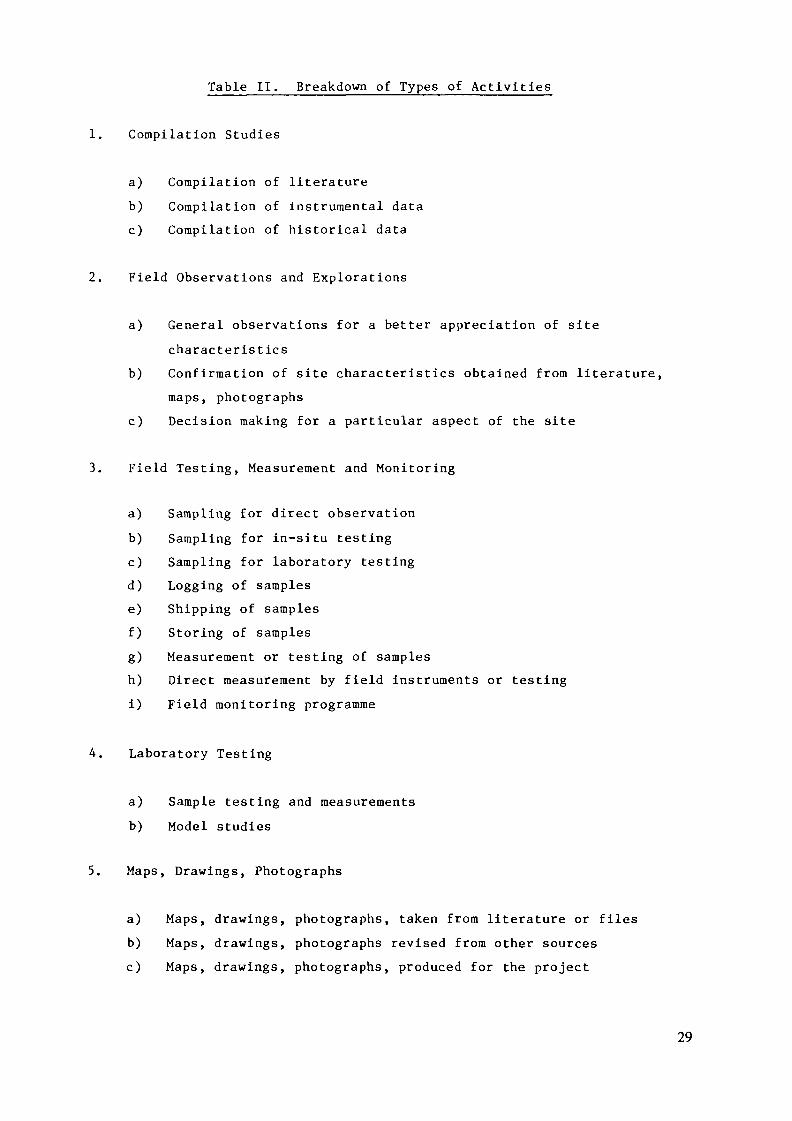
Table II. Breakdown of Types of Activities
1. Compilation Studies
a) Compilation of literatureb) Compilation of instrumental datac) Compilation of historical data
2. Field Observations and Explorations
a) General observations for a better appreciation of sitecharacteristics
b) Confirmation of site characteristics obtained from literature,maps, photographs
c) Decision making for a particular aspect of the site
3. Field Testing, Measurement and Monitoring
a) Sampling for direct observationb) Sampling for in-situ testingc) Sampling for laboratory testingd) Logging of samplese) Shipping of samplesf) Storing of samplesg) Measurement or testing of samplesh) Direct measurement by field instruments or testingi) Field monitoring programme
4. Laboratory Testing
a) Sample testing and measurementsb) Model studies
5. Maps, Drawings, Photographs
a) Maps, drawings, photographs, taken from literature or filesb) Maps, drawings, photographs revised from other sourcesc) Maps, drawings, photographs, produced for the project
29

6. Calculations
a) Data processing, reduction of test datab) Calculations for derivation of preliminary design parametersc) Calculation for derivation of final design parametersd) Calculations to assess sensitivity of results to input
parameters
7. Computer Programmes
a) Industry standard computer programmesb) Development of software for well established algorithmsc) Development of software for new algorithmsd) Adaptation of programmes to other computers
30

4. QA PROGRAMME DOCUMENTATION
4.1 General
The quality assurance programme should be established consistentwith the requirements of the Code as an integral part of the nuclearpower plant project. This programme should be documented in anappropriate QA programme description, programme procedures, work plansand schedules, and work procedures and instructions. The responsibleorganization or its désignée is responsible for assuring that all sitingactivities are performed by qualified personnel in accordance with theplans, procedures and instructions documenting the QA programme. Theprogramme documentation should be subject to control as required by theCode and relevant Safety Guides. It is important to identify and provideto the regulatory body,if required, appropriate QA programme descriptionon matters related to siting activities for their review and approval.
4.2 QA Programme Description
Section 4.2.1 of Safety Guide 50-SG-QAl, provides the necessaryrequirements and recommendations concerning the QA programme description.
The QA programme desciption provides guidance for programmeimplementation and a concise description of what the programme containsand how it functions. It should cover the requirements of the Code insufficient detail to provide a knowledgeable reviewer with the confidencethat all quality assurance requirements have been identified and fullydeveloped in the quality assurance programme. It also provides a formalstatement by the management of the organization of its commitment to:implement the quality assurance programme activities for which it isresponsible; review the programme periodically, and amend the programmeas necessary to keep it up-to-date and effective.
The quality assurance programme description should include, but neednot be limited to, the following items:
(1) A statement of policies and objectives.(2) A clear definition of the items and services covered by the QA
programme.
31
(3) The organizational structure within which the quality assuranceactivities are to be planned and implemented.
(4) A delineation of the responsibility and authority of thevarious organizations and personnel involved in the programme.
(5) A description of the procedures which will be applied to theprogramme. Reference should be made to both existingprocedures and those requiring development.
(6) A description of the procedures for the identification,planning and control of the work to be performed. Referenceshould be made to applicable programme procedures andwork-oriented documents such as the working procedures,instructions, and drawings which will be used in the qualityassurance activities.
(7) A description, referenced to the appropriate programmeprocedures, of the method to be adopted for the planning andperformance of audit and review activities.
(8) A description of provisions for the training of personnelperforming activities affecting quality.
The complete description of the quality assurance programme shouldbe bound and suitably indexed to identify both content and revisionstatus.
The quality assurance programme descriptions should be approved by asenior management official of the organization identified therein toconfirm the accuracy of the information and the validity of thecommitment by the organization.
4.3 QA Programme Procedures
Section 4.2.2 of Safety Guide 50-SG-QA1, provides the necessaryinformation concerning the QA programme procedures:
"Activities affecting the quality of a nuclear power plant shall beprescribed by appropriate written procedures. These procedures are of aprogrammatic nature and they shall expand on the policies and plannedactivities presented in the quality assurance programme description andshall provide specific detail on how the activities are to be performed.
32

The extent of the details presented depends on the experience andtraining of the individuals performing the work and the procedures shallbe written in such a way as to provide an appropriately qualifiedindividual with the information necessary to perform his function. Whereappropriate, the document shall be supplemented with a selection oftypical reports, forms, tags, stamps, in support of the statedcommitments."
QA Programme procedures represent a management tool for directingthe total effort in a planned and systematic manner both for internalpurposes within the participant's organization and for the co-ordinationof the participants' activities with those of other tiers. Suchprocedures are primarily concerned with management strategy and forexample, provide direction as to the responsibilities and sequence ofevents to be followed in the preparation, approval and control of workinginstructions, procedures and drawings. QA programme procedures do notnormally include technical data since these are contained in workinginstructions, procedures and drawings. Specific references should bemade to these working documents where appropriate.
QA Programme procedures should provide detailed information anddirectives for the performance of tasks and they should be set down in alogical sequence, in a standardized format. A typical format would be asfollows:
Purpose: The purpose for which the procedure exists should bebriefly and concisely stated.
- Scope: The boundary of the procedure should be delineated.- Definitions: Definitions should be given of technical terms
used in the text that are uncommon or have meaningspecific to the procedure.
- References: Sources of further information which may be necessaryfor understanding the background to specific actions, e.g.procedure interfaces, should be quoted.
- Responsibilities: Primary responsibilities for the successfuloutcome of the procedures should be identified. Theresponsibility for specific activities will be a feature of theactions.
- Actions: The step-by-step sequence of actions to be performed inorder to achieve the purpose of the procedure should be given.
33

Documentation: The forms, to be used for communicatinginstructions, information and results should be specified.
- Records: The records to be generated and their classificationshould be specified. Reference should be made to otherprocedures which govern the filing, storage and retention ofrecords.
All QA programme procedures may be grouped together in a document usuallycalled Quality Assurance Manual.
4.4 Work Plans and Schedules
Work plans and schedules should be established to assure a plannedand systematic acquisition of data and professional evaluations toestablish site-related parameters for the nuclear power plant. Theyshould provide for the identification and scheduling of activities.
The complexity of the activities, the diversity of the disciplinesinvolved and their interrelationship require complex planning. It istherefore expedient to adopt a hierarchy of plans in which each tiercomprises sub-plans which provide more details than the higher-tier plan.An overall plan is used as a means of collating the planning ofsub-groups and work delegated to other organizations. The work plans andschedules may take the form of work task description, including flowcharts, schedules, or other material as appropriate to the circumstances,type of activities and siting practices.
The work plans and schedules should reference applicable QArequirements, such as programmatic and work oriented procedures andinstructions which specify activities to be performed.
Example of work plan format is given in Annex I Exhibit 1.
4.5 Work Procedures and Instructions
Work procedures are detailed directives on how general or specificactivities, specific processes, field tests, laboratory tests, functions,and verifications are to be performed. They delineate explicit
34

step-by-step actions to be taken, in order to assure that the workperformance and obtained results will comply with predeterminedrequirements. Work procedures should include details on data required,method of data collection, forms to fill in, and reports to prepare.Where an industry standard is to be followed, each step within thestandard should be reviewed for its applicability to the project. If anyportion is not applicable or will be modified, this should be noted inthe controlled copies of the respective standard and in the workprocedures.
General type activities subject to the QA programme should also becovered by work procedures. Typical examples of such procedures are:
- Review Process Procedure - this includes the review method, theidentification of the reviewers, the review schedule, theretention of all comments and the indication of theirresolution.
Reporting Format Procedure - this includes delineation of thepage size, margins, page numbering system, heading systemincluding numbering type style and the spacing, referencecitation form and method of indication of revisions.
Drawing Format Procedure - this includes orientation on page,page size, scale, title block, margins, location of legend anddrawing symbols.
- Project File System Procedure - this includes the loggingsystem for all documents including literature, maps, drawings,computations, laboratory analysis, photographs, andcorrespondence.
Work procedures should also be prepared for specific activities inthe framework of applicable technical disciplines. It should be notedthat each such technical discipline is comprised of a number of specificactivities, each of which requires a work procedure. Examples of workprocedures for selected activities are given in Annex II, Exhibit: 1and 2.
35

The IAEA is in the process of producing a detailed set of workprocedures for the compilation of historical earthquake data under atechnical cooperation project. This document is expected to be publishedin 1987.
An instruction is a directive which defines the administrative andtechnical steps to be followed in the performance of a specific task. Aninstruction normally documents the assignment of responsibility to anindividual to perform a task in accordance with certain procedures.
Instructions are written for individuals with the lowest level ofqualification normally required for the activities involved.Consideration should also be given to the equipment, facilities andenvironment. Careful attention to all these factors during preparationof the instructions and specification of the personnel training requiredwill result in a good fit between the people performing the work, theinstructions, and the facilities.
For example, instructions to staff typically include reference toprocedures to be followed, definition of responsibilities and authorityfor the specific task, reporting method and schedule (e.g., if the taskinvolves field work, the work instruction should include a description ofthe type of data to be collected, the format for collection, and thereporting method: e.g. daily reports, telephone).
In Annex I, Exhibit 2 an example is given of a form for use in thepreparation of a work instruction.
4.6 Manuals
All activities affecting quality of the siting process should becovered by written procedures or instructions which might be groupedtogether in a number of manuals related to specific project activities ortechnical disciplines of power plant siting. The QA programmedescription should identify typical activities that should be covered bythe QA programme and should describe the procedures and instructions that
36

should be included in the respective manual. Typical manuals developedfor a siting process are the following:
4.6.1 Project Management Procedures Manual
This manual includes procedures used for the management control ofthe project. These are procedures established and approved by theresponsible manager and contain appropriate policies,responsibilities and operating instructions which define how theproject will operate and how it will interface with other existing(divisional, technical discipline or other) policies andprocedures. They normally apply to all project activities.
Procedures may be issued to provide specific project relatedinstructions regarding an administrative aspect of the project.
Typical project management procedures include:Task assignmentScheduling and Work ProgrammeLetter format
- Review process proceduresReport formatTrip reportsDaily field reportsRecord of telephone callsMeeting notesProject related travelPreparation of project instructions.Drawing format
4.6.2 Technical Disciplines Procedures Manual
Technical Discipline Procedures Manuals include procedures used forperformance and verification of work activities inside a technicaldiscipline, such as geology, hydrology, seismology and foundationengineering. They contain requirements or instructions on how todirect actions within a technical discipline, how to controlinterfaces between technical disciplines and how to verify theresults obtained.
37

Normally, the Manual for a technical discipline should include allwork procedures and instructions identified in the QA programmedescription as necessary, both for the performance of the work andfor verification of activities such as by inspections and tests.
Separate Procedure Manuals can be developed for each of thetechnical disciplines identified in Table I or they may be groupedtogether in one Manual covering procedures for activities common toall technical disciplines. Procedure applicable to all tasksperformed in the office, in the field, and in the laboratory shouldbe included in the appropriate Procedure Manual.
4.6.3 QA Manual
QA programme procedures might be grouped together into the QAManual. A typical QA manual covers all the aspects of the QAidentified in the respective QA requirements and standards. TypicalQA programme activities covered by procedures are listed in Annex I,Exhibit 3. An example of a typical QA programme procedure is givenin Annex I, Exhibit 4.
38

5. ORGANIZATION
5.1 General
The Code requires, that a documented organizational structure, withclearly defined functional responsibilities, levels of authority andlines of internal and external communication for management, direction,and execution of the quality assurance program shall be established. Theorganizational structure should include the contractors, sub-contractorsand consultants involved in the siting process.
The responsible organization should prepare a project organizationalchart indicating all the parties involved with the project and clearlyshowing the interfaces between them and lines of reporting andcommunication. The main contractor, subcontractors and consultantsshould also prepare organizational charts for the tasks in which they areinvolved. These organizational charts should clearly indicate theresponsible persons for different parts of the task. The position of theQA unit inside the project organization should be indicated includinglines of reporting to the management and communication with otherorganizational units.
Examples of such charts are shown in the IAEA Safety Guide onQuality Assurance Organization for Nuclear Power Plants, in Annex VIIthrough Annex X (IAEA Safety Series No. 50-SG-QA7, 1983). An example ofan organizational structure of a responsible organization performingsiting activities is given in Annex I, Exhibit 5.
5.2 Staffing of Personnel
Staffing plans shall be developed as required by Sec. 2.5.1 of theSafety Guide on QA Organization for Nuclear Power Plants, No. 50-SG-QA7.These plans shall identify each position or type of position for whichthere are qualification requirements. A position description should beprepared for each such position assigned to the project. This descriptionshould include:
Position titlePosition objective
39

ResponsibilitiesAuthoritiesEducation and experience requirementsSupervisory responsibilities
An example of the type of form used in preparation of a positiondescription is shown in Annex I Exhibit 6.
5.2.1 Functions and Responsibilities of Project Managerfor Siting Activities and QA RepresentativeResponsible for Siting Activities
The responsibilties of the Project Manager for Siting Activities(hereinafter referred to as the "Responsible Manager") and the QARepresentative Responsible for Siting Activities* should be asfollows:
The Project Manager for Siting Activities (Responsible Manager), isresponsible for:
1) Determining the responsibility, providing plans, andidentifying internal and external interfaces for the sitingproject organization and providing lines of directions andcommunications between both internal and external groups.
2) Overseeing the effective implementation of all QA functions bythe siting project team.
3) Ensuring the establishment of QA requirements for the sitingproject team, consultants and other contractors; ensuring theapproval of their QA documents such as QA manual and programmeprocedures.
4) Approving the Work Plans and Schedules.
* The responsibilities of the Project Manager and QA Representative forSiting Activities are usually transfered to other appropriate personnelafter completion of site evaluation phase.
40

5) Ascertaining standards, codes, guides and procedures applicableto the siting project and directing the development andapproval of specific procedures and instructions to be used inthe course of site selection activities.
6) Establishing the siting project file system.
7) Reporting on an established schedule, to the management of theresponsible organization, on the regular development of thesiting project, as well as when problems and deficiencies areidentified in the siting process and providing the approach andschedule for the resolution of problems and deficiencies.
8) Recommending the resolutions of non-conformances anddeficiencies when appropriate.
9) Proposing, reviewing and approving corrective actions.
The QA Representative for Siting Activities, is responsible for:
1) Ensuring the effective implementation of the siting QAprogramme.
2) Co-ordinating the QA functions of the siting project team;maintaining the QA programme description and issuing allrevisions to the description.
3) Evaluating and issuing the approval of main suppliers' QAprogrammes and relevant documents such as QA manual andprocedures; recommending their inclusion on the approvedsuppliers list.
4) Reviewing and approving QA requirements for the procurement ofservices and equipment.
5) Preparing and controlling the implementation of QA procedureswhich should be implemented by the project team in the courseof project activities.
41
6) Reviewing and ensuring prior to approving that QA requirementsare included in work plans and schedules as well as in workprocedures and instructions to be used in siting activities.
7) Establishing a surveillance and inspection schedule(hold/witness points) and performing on-the-job surveillance ofsite investigation activities and recording results obtained.
8) Initiating the preparation of non-conformance reports whendeficiencies in the activities are identified.
9) Organizing audits of the QA programme of suppliers; identifyingdeficiencies in the programme and ensuring implementation ofcorrective actions.
10) Participating in the activities of the siting review committee.
11) Organizing and conducting QA programme orientation courses forthe project team personnel.
12) Identifying conditions adverse to quality, and ensuring thatcorrective action is taken, including action to preventrepetition for significant conditions adverse to quality.
13) Co-ordinating with QA groups of all contractors and suppliers.
14) Organizing planning, preparation and performance of theinternal QA programme audits.
15) Reporting to the management of the responsible organization ofthe status of QA activities.
5.3 Qualifications and Training of Personnel
Each staff member assigned to the project should have an experiencerecord in the project file. This experience record will be used to verifythat the employee has the education and experience required to performthe level of tasks defined in the position description for his/herspecific assignment. The project manager or his désignée should maintain
42

experience/qualification records of project personnel. An example of thetype of information to be included in this record is shown in Annex I,Exhibit 7.
The training requirements for a specific position should beidentified by the responsible manager. Upon completion of requiredtraining, the training record should be prepared for each individual thatcompleted its training satisfactorily. Training requirements andtraining record are normally documented in the forms such as shown inAnnex I. Exhibit 8.
The responsible manager and/or applicable supervisor should sign anemployee qualification statement indicating the employee is qualified forthe position described in the position description based on the specifiedrequirements for education, experience, indoctrination and training.Such information should be maintained by the responsible manager or hisdésignée for staff performing quality related work. These records aresubject to audit.
For additional information on training, qualification andcertification of QA personnel refer to the IAEA Manual on Training,Qualification and Certification of QA Personnel, Tech.Rep. SeriesNo. 262, 1986.
5.4 Quality Assurance Training of Consultant's Personnel
Specific studies related to the siting process, in particulargeotechnical, seismological, meteorological, demographical, may bedelegated to different consultants. The procurement documents for theseservices should also specify training and qualification requirements forpersonnel for each specific task related to these studies includingtraining and qualification of QA personnel.
The consultant or his désignée should be responsible for providingorientation and training of its personnel in the QA requirements and anyother requirements applicable to the consultant's assignment.
43
5.5 Siting Review Committee
In the framework of the organizational structure of the nuclearpower project, an independent Siting Review Committee may be formed*.The functions of this committee are the review and evaluation of reports,studies and analysis related to the siting process which are identifiedas safety related and which represent a direct input into the futuredesign of nuclear power plants.
The responsible manager should determine activities and reports thatrequire review by the Committee and should be responsible for the issueof the Siting Review Committee Request. The responsible manager shouldappoint a review committee chairperson, and should determine the type ofreview to be conducted. An example of Review Committee Meeting Noticewith indication of attending persons and agenda is given in Annex 1,Exhibit 9.a.
The Siting Review Committee should be composed of persons notdirectly responsible for the work being reviewed and evaluated and whichshould include: the responsible manager or his désignée, the QArepresentative for siting activities or his désignée, and one or morespecialists in the area of the relevant work but not primarily engaged inthe work.
The responsible manager should designate specialists for the SitingReview Committee to conduct the review and evaluation. The responsiblemanager should ensure that designated review committee member'sbackground experience and capability is documented and evaluated forapplicability to the discipline and material they are to review andevaluate.
(See Section 6.7.5 for description of review and evaluation of thework by the Siting Review Committee).
* when Siting Review Committee is formed, it normally is disbanded uponcompletion of site evaluation phase.
44

6. QA PROGRAMME IMPLEMENTATION
6.1 General
QA programme requirements specified in the Code and formulated anddocumented in the programme procedures should be implemented for allservices required to be included in the scope of the QA programme. Eachorganization performing tasks affecting the quality of siting which arerequired to be included in the QA programme should implement therequirements by subjecting activities to controls specified in the Code.These controls are, according to the Code:
Document controlControl of studies, evaluations and analyses (analogous todesign control in the Code)Procurement controlMaterial controlProcess control
- Quality verifications (analogous to inspection and test controlin the Code)Non-conformance controlCorrective action
- RecordsAuditing.
Each of these control functions should be prescribed by one or moreQA programme procedures providing methodology for implementingrequirements of the specific section of the Code.
In the following sections, typical QA activities related to theservices to be performed during the siting process are described.
6.2 Document Control
Procedures should be prepared for the control of documents used inall activities related to the siting process for nuclear power plantsthat are subject to the QA programme. These procedures shall as a minimum
45

provide for:
- Identification of correct documents and versions of documentsto be used in activitiesMaintenance of current distribution lists.Control measures to ensure that only correct and applicabledocuments are being used.Marking or otherwise identification of obsolete documents fortheir retraction or disposal
- Maintenance of a record of document distribution.
Documents that should be subject to control should be identified andshould include:
- Programme ProceduresWork Plans and SchedulesProcurement DocumentsWork Procedures and InstructionsDrawingsTechnical Specifications
Document changes and revisions should be reviewed and approved bythe same organization that performed the original review and approval orby another delegated qualified organization. An example of a Procedurefor Document Control is given in the Annex I Exhibit 4.
6.3 Control of Studies, Evaluations and Analyses
Preparation and performance of studies, evaluations and analysesshould be subject to control. This control should include:
Identification of general documents to be used in activitiessuch as regulatory requirements, and engineering codes andstandards.
Identification of the source of the data and their reliabilitywhen input data for an analysis are used.
Identification of the required qualification of individualsperforming the evaluations and analyses.
46

The activities related to the studies, evaluations and analysessubject to the QA programme should be carried out in accordance withprescribed procedures. Documents such as procedures, work instructions,planning sheets should be reviewed by personnel having experience in thesubject activities.
Studies, evaluations and analyses should be sufficiently detailed asto purpose, method, assumptions, data inputs, references and units that aperson technically qualified in the subject area can review and verifythe adequacy of the results. Studies, evaluations and analyses shouldalso be identifiable by subject, originator, reviewer and other data. Ifa computer is used, the computer code should be checked in an approvedand documented manner prior to its use or application.
When studies, evaluations and analyses are based upon the factorsthat are difficult to subject to direct verifications such asprofessional experience of experts or their judgement, enoughjustification of the assumption taken, the methods used or selection ofappropriate site-related parameters should be presented. This shouldallow the reviewer to understand the approach and accept the result ofthe studies, evaluations and analyses.
The results of studies, evaluations and analyses should bedocumented. This documentation should be legible and should be in a formsuitable for reproduction, filing and retrieving.
6.4 Procurement Control
6.A.I General
For the procurement of services and equipment, relevant QA measuresshould be applied. These measures should include the followingprocurement activities relevant to siting:
(a) Procurement document preparation and control(b) Selection of services and equipment(c) Bid evaluation and award of contract(d) Control of contractors' performance(e) Acceptance of services or equipment
47

IAEA Safety Guide on Quality Assurance in the Procurement of Itemsand Services for Nuclear Power Plants (IAEA Safety Series, No.50-SG-QA3, 1979), provides requirements and recommendations relatedto the establishment, implementation and administration of thevarious procurement activities which are applicable to the sitingprocess.
6.4.2 Procurement Document Preparation and Control
All procurement documents related to the supply of services orequipment should include as a minimum:
- The detailed description of the scope of work (services orequipment specification) to be suppliedThe reference to appropriate regulatory and technicalrequirements
- Requirements for applicable QA programme or other controls tobe implemented by the supplierDocumentation requirements
- The right of access by the purchaser to facilities anddocuments or other information relevant to the procuredservices or equipment for the purpose of inspection and audit
- The obligation of the supplier to notify the purchaser of thetime for specified witness and hold points
- Requirements for reporting and approving disposition ofnon-conformancesThe method of acceptance of services or equipmentExtension of requirements to lower tier contractors
- Requirements for turn-over of records to the purchaser.
The procedures should be established for preparation, control,review and approval of procurement documents before issuance. Theprocedures should identify competent personnel for approval andissuance of the procurement documents.
Procurement documents should be controlled in accordance withsection 4 of the Code.
48

6.4.3 Selection of Suppliers of Services and Equipment
The selection of suppliers should be based on the evaluation resultsof their capability to provide either services or equipment inaccordance with the requirements of the procurement documents.
The purchaser should establish a method for evaluation and selectionof suppliers. Such a method should include provisions foridentifying the various organizational units responsible fordetermining the suppliers' capabilities. Methods to be used inevaluating suppliers and the results therefrom should bedocumented. Results of the evaluation process should render thesupplier either suitable or not suitable for supplying the serviceor equipment.
6.4.4 Bid Evaluation and Award of Contract
The purchaser should establish a method for evaluating the qualityaspects of bids and for awarding of contracts. Such a method shouldinclude provisions for ensuring that the bid conforms to theprocurement document requirements. These provisions should include,as a minimum, review of:
Technical considerationsQA requirementsResearch and development effortSupplier's personnelSupplier's performance/production capabilitySupplier's past performanceAlternatives to the procurement document requirements
- Exceptions from the procurement document requirements.
6.4.5 Control of Suppliers Performance
The purchaser should monitor and evaluate the suppliers performanceto the specified requirements of the procurement document. Duringthe performance of services subject to the QA programme, controlsshould be implemented at the suppliers' facilities, and/or in thefield. These controls should include inspection and surveillance of
49
suppliers in accordance with procurement documents and establishedwork plans and schedules. This should include inspections orwitnessing at those control points beyond which the work cannotproceed without approval.
The control measures should also include periodic auditing of the QAprogramme of the suppliers. These audits should be performed inaccordance with the Code and Section 6.10 of this Manual.
6.4.6 Acceptance of Services or Equipment
The final acceptance of procured services or equipment shouldrequire a succesful verification of the submitted reports, drawings,evaluation, calculations, laboratory equipment, field equipment, orfield monitoring systems as specified in procurement documents andin accordance with section 6.6.
The acceptance process should take into consideration the results ofthe surveillance, inspection, and auditing activities as specifiedin the procurement documents. Records of the QA activities carriedout during performance of the work should be attached to thesuppliers' final report for review and formal acceptance of the work.
All purchased equipment should be subject to inspection and testingbefore the final acceptance. The inspection and tests should verifythe conforraance of supplier equipment and instruments tospecification given in the procurement documents. The inspectionshould include the identification of type and class of equipment aswell as the received condition of equipment. When the quality isspecified, the inspection should include the review of objectiveevidence of the quality such as inspection and test certificatesand calibration certificates. For specified types of equipment andinstruments procedures should be prepared to describe the type andextent of inspection. The results of inspection should bedocumented.
50

6.5 Material Control
6.5.1 General
Procedures should be prepared and implemented for identification andcontrol of materials, equipment, instruments and samples duringhandling, storage and shipping. These procedures should includerequirements for cleaning, packing, preservation and identificationof these items, to prevent deterioration and loss. For materialsand samples of limited life time, the date of manufacture oracquisition, cure date and expended life should be identified.Samples collected during site investigations, and monitoringprogramme (e.g. water, soil, rock) are to be catogorized andconsidered archival material, catalogued and stored to precludedeterioration or loss. These samples may include but should not belimited to: soil, rock, surface water and ground water. Anexample of the document used in the control of shipment of samplesand of their receipt is presented in Annex I, Exhibits 10 and 11.
6.5.2 Handling, Shipping and Storage of Samples
Proper treatment of materials obtained from field investigationssuch as samples from subsurface exploration, is critical to theirquality. For example, samples of undisturbed cohesionless orcohesive soil require extreme care during removal from the boreholeand sampler and during subsequent handling to prevent disturbancefrom impact, vibration and excessive temperature changes. Samplesshould be placed in noncorroding, airtight containers, properlylabeled, identified, and sealed and protected against moistureloss. The containers should be kept in a vertical position at alltimes. They should be well insulated and protected from vibrationand impact and transported with extreme care.
Disturbed samples may be sealed in the same manner as undisturbedsamples. Large representative samples may be placed in plasticbags, in tightly woven cloth, or in noncorroding cans that do notpermit contamination or loss of fine particles. Such samples may betransported by any convenient means.
51
Rock cores should be stored and transported in durable boxesprovided with suitable dividers to prevent damage or shifting of thecores in any direction. They should be clearly labeled to identifythe site, the boring number, the core interval, the length of corelost or not recovered in each core interval and the top and bottomdepths of the core interval. If the box has a removable lid,labeling should be placed on both the outside and inside of the box,as well as on the lid. Core samples should be transported with thecare necessary to avoid breakage, disturbance and contamination.Samples should be properly catalogued and stored under controlledconditions until the plant is decommissioned or until authorizationto discard it is recived from the responsible organization.
6.6 Process Control
Activities requiring special skill, equipment or processing shouldbe identified and subject to control. Such controls should include theidentification and the qualification of personnel that performactivities, the identification and qualification of equipment to be used,and the preparation and qualification of procedures and instructions forperforming activities. Control and verification of such activitiesshould also include monitoring and surveillance of the activities andinspection and review of the product or results of the work. The extentand type of verification of the work and results at the verificationshould be documented.
6.7 Quality Verifications
6.7.1 Reviews of Studies, Evaluations and Analyses
For each study, evaluation and analysis subject to the QA programme,the responsible manager or his désignée should designate one or moreindividuals, groups or organizations to verify the obtainedresults. Designated verifiers should be persons not directlyresponsible for that task. The verification should be performed onthe basis of review and evaluation of the results of the work. Thereviewers and other verifiers should check to ensure that therequirements of the scope of the work have been satisfied, that thetechnical approach used and the method of analysis are valid and theresults of analysis are correct.
52

The results of the verification efforts should be sufficientlydocumented to allow for surveillance or auditing of the reviews andchecks so as to permit confirmation that the process has beenproperly implemented. Identification of the reviewers and otherverifiers should be clearly indicated and dated.
The records of reviews should be submitted to the responsiblemanager for approval. His responsibility should be to performassessment of the results of the performed reviews. The approval ofverification should be marked by his signature. One way ofdocumenting the review of studies, evaluation and anlyses is givenin Annex I, Exhibit 12.
6.7.2 Field Activities Verification
For field activities, such as subsurface exploration andmeteorological measurements, verifications should be provided toensure that the activities are being performed by qualifiedpersonnel according to established procedures and using specifiedequipment. These verifications should be performed prior to andduring field operations. The items and activities to be checked andverified should include:
compliance with the work plan and proceduresqualification of personnelidentification and control of documentsmonitoring of activitiesmethods of sampling (e.g. soil, rock, water)classifying, logging and reporting methodsidentification, handling and storing of samples.
Records of all field activities verifications should be reported toappropriate management and should be maintained as a qualityassurance record.
6.7.3 Laboratory Activities Verification
During the performance of laboratory analyses and testing,verifications should be performed to ensure that the activities arebeing performed and conducted according to procedures, by qualified
53

personnel using specified equipment. The elements to be verifiedshould include:
existence and implementation of the laboratory QA programmequalification of laboratory personnel
- calibration and control of measuring and test equipment- identification, control and storage of samples
document control procedures and practicesexistance and use of standard test methods and qualified testprocedure in accordance with applicable standards andrequirements
- documentation of test data, results, conditions andobservations.
Records of all laboratory analyses and test programme verificationsshould be reported to appropriate management and maintained asquality assurance records.
6.7.4 Verification of Calculations and Computer Software
Calculations should be originated and verified according toprescribed procedures. An example of a procedure for preparation andreview of computations is given in Annex II., Exhibit 3.
The computer codes used for calculations and analyses should beverified and documented. The verifications should be done for allprogrammes prior to their use and should be applied to: newprogrammes, modified versions of an existing programme and alsoexisting programmes. The verification should be performed on thebasis of the established procedure. The scope of verificationshould include: mathematical modelling, numerical analysis,standard tests case data library, benchmarks against existingprogrammes, or against hand calculations. All the programmes shouldbe documented in sufficient detail so that each can be understoodand verified by a qualified reviewer. For programme documentationthe existing recognized standards should be used or a procedureshould be developed.
54

All verifications of computer software should be documented on therecord of computer software verification. For additionalinformation related to quality assurance for computer software, seeIAEA Manual on QA for Computer Software (to be published).
6.7.5 Review and Evaluation of the Work by theSiting Review Committee
The responsible manager should identify the reports/analyses andother technical documents resulting from the work that requirereview and evaluation by the Siting Review Committee and shouldsubmit a formal request to the Committee for review. Subsequentlythe chairperson of the Committee should issue a notice to SitingReview Committee members scheduling a meeting for disposition ofdocuments reviewed. An example of the review committee meetingnotice form is presented in Annex I, Exhibit 9a.
In the request for review the responsible manager should identifythe scope of the review, the review objectives, review requirementsand guidelines documents, and the personnel who will conduct thereview. Each Siting Review Committee member should review theidentified document with special emphasis on the area of expertiseas noted in the request. To facilitate reviews of documents wherecomments are generally referenced to a specific page and line,Siting Review Committee reports are usually prepared on a form suchas the one shown in Annex I, Exhibit 9b.
The type of expertise review should be designated. This may include:
Formally convened review group within the CommitteeUse of an independent contractor or consultantAn independent review conducted within the project organizationAny combination of the above.
All review comments and resolutions should be reviewed by thechairperson or their désignée with the person making the comment andshould be resolved, i.e., accept, reject or partial acceptance, and theassociated rationale should be stated.
55
The chairperson should prepare or direct the preparation of thereview committee report. The review report should, as a minimum, consistof the following items:
o The Siting Review Committee request for reviewo The Siting Review Committee check list formo The Siting Review Committee comment and resolution formo The Siting Review Committee meeting minutes (if applicable)o The siting summary of the review comments.
The Siting Review Committee chairperson should submit the reviewcommittee report to the responsible manager for approval. Theresponsible manager should assure that the completed review committeerecords are entered into the project records. The report should not beclosed until all the comments have been resolved.
All deficiencies, uncompleteness or identified incorrectness in thereports/analysis should be considered as non-conformances and be handledaccording to Section 6.8. of this Manual.
6.7.6 Calibration and Control of Measuring and Test Equipment
The measuring and test equipment used for data acquisitionthroughout the siting process should be subject to control. A procedureshould be established for the calibration of this equipment to ensurethat the accuracy is maintained within the prescribed limits and that therequired reproducibility and traceability is present. The procedureshould specify recalibration intervals and reference to appropriatestandards traceable to recognized national or international standards.When necessary, the procedure should include the instruction for thecalibration performance.
The calibration of each equipment and instrument should berecorded. These calibration records are quality assurance records andshould be retained and maintained.
An example procedure for calibration and maintenance of measuringand test equipment is given in Annex II, Exhibit 4. Sample label to beplaced on measuring and test equipment and samples of field calibrationrecords are presented in Annex II, Exhibit 5.
56

6.8 Non-conformance Control
A procedure should be established for reporting any non-conformancesto prescribed specifications or procedures. As a non-conformance oneshould consider any deficiency in characteristic, documentation orprocedure, which renders the quality of equipment, materials or samplesor obtained results of a study or an analysis, unacceptable orindeterminate. The procedure should include a reporting form calledNon-conformance Report, NCR, such as the example shown in Annex I,Exhibit 13, which will be addressed to the responsible manager and to theQA representative. Non-conformance reporting may be initiated by anymember of the project team.
The NCR should include a brief description of the deficiency and theproposal of the action to correct the non-conformance. Fornon-conformances discovered during surveillance or audit activities thenon-conformance report should be a part of the surveillance or auditreport and should be referenced in them.
The responsible manager should be responsible for proper review anddisposition of the reported non-conformance. When it is deemed necessarythe responsible manager may request the Siting Review Committee to makerecommendations before the disposition is made or, in some cases, on theproposed disposition. The disposition of the reported non-conformancesand the corrective action taken should be documented.
6.9 Corrective Action
The responsible manager should ensure that conditions adverse toquality are identified and corrected and, for significant conditions, thecause is determined and corrective action is taken to preventrepetition. Reports of the identification of significant conditionsadverse to quality, the cause of the condition and the corrective actiontaken should be documented and reported to the responsible manager.
When déficiences are discovered in these reports they should bereturned to the originator for further action as requested by the SitingReview Committee or responsible manager.
57

6.10 Records
Sufficient records should be retained to provide evidence of theperformed work in the scope of the siting process. In determining theamount and form of records to be retained the criteria to be used arethat the retained record should provide the necessary support of thevalidity of the work and should allow that the steps in the workperformance can be identified and re-created as necessary. These recordsshould include the basis for ranking of potential site areas, the reasonsfor rejection of unacceptable site areas, the data collected and theresults of analyses performed for the accepted site. These records shouldinclude the justification for rejection of unacceptable site areas, thebasis for ranking of potential site areas, data collected and the resultsof analyses performed for the accepted site.
Procedures should be established for identification, handling,filing, storage and retrieval of QA records. These procedures arenormally applicable to all the nuclear power plant project records.
A project record file system should be established based on anindex. The system should provide for easy retrievability so thatpersonnel not directly responsible for the record administration mayretrieve a record without problems. The record system should includeprovisions for documents in process (working files) and final recordfiles. The procedure should include provisions for the classification ofrecords and their authentication. Records should be categorized withrespect to the retention time as permanent and non-permanent. PermanentQA records are those which provide evidence that might be of use for thelifetime of the plant and they should be maintained for the lifetime ofthe plant.
Non-permanent QA records are those not needed for the lifetime ofthe plant. For these records the retention time should be determined.The categorization of records with respect to type and retention timetogether with a stamp or a signature of the person authorized toauthenticate the record should be clearly marked on each record and onthe outside of the file folder.
58

The procedure should include provisions for the storage of completedrecord files. It should also include provisions for controlling of theaccess to completed record files as well as the removal of files orseparate records. Storage areas for files should be locked in order topreclude the unauthorized removal of records. For further informationrelated to the QA records system refer to the IAEA Safety Guide onQuality Assurance Records System (IAEA Safety Series No. 50-SG-QA2, 1979).
6.11 Audits
Internal and external audits of the QA programme should be plannedand conducted to verify compliance with the QA programme requirements andimplementing procedures and to determine the programme effectiveness.
Procedures should be established for audits scheduling, preparation,conduct and follow-up, as specified in the IAEA Safety Guide on QAAuditing for Nuclear Power Plants (IAEA Safety Series No. 50-SG-QA10,1980). Methodology of audits for QA programme for siting should beidentical to all nuclear power plant audits. Recommendations andillustrative examples on QA programme auditing are given in the Manual onQA Programme Audits (IAEA Technical Reports Series No. 237, 1984).
After completion of external audit, the audit report should beaddressed to the audited organization with copy to the responsiblemanager. The schedule for the submission of audit reports should beestablished as well as for preparation and submission of the reply toaudit. For internal audits the manager of the organizational unit beingaudited should review the audit findings and report to the responsiblemanager on intended follow-up actions.
For external audits the management of the audited organizationshould respond to the audit report. As a minimum the reply shouldinclude a plan for implementing corrective action to be taken ondeficiencies indicated in the audit report.
Records of all audits should be maintained in the QA record files.As a minimum these records should include the audit plan the audit reportand responses to the audit report and evidence of completion ofcorrective action, as well as any relevant documents produced during theauditing process.
59

ANNEX I:
EXAMPLES OF DOCUMENTSUSED IN THE SCOPE OF THE QA PROGRAMME
FOR THE SURVEY, EVALUATIONAND CONFIRMATION
OF NUCLEAR POWER PLANT SITES
61

Annex I, Exhibit 1EXAMPLE OF WORK PLAN FORMAT
(cited in para. 4.4)
FORMAT FOR WORK PLAN
Introduction Identifies the programmatic objective to be metby the Work Plan, or in other words, why WorkPlan is needed.
Purpose Discuss the purpose of the specific work tasks(e.g. drilling, geophysical borehole logging,laboratory testing, analysis) needed toaccomplish the identified programmatic objective.
Scope of work Statement of the work to be accomplished and theform of the final product such as a report,calculations, drawings. Work activities thatwill be excluded (i.e., not covered by this WorkPlan) should also be referenced in the scope.
Definitions Definitions should be given of technical termsused in the text that are uncommon or havemeaning specific to the procedure.
References/Requirements Identify governing procedures, specific workinstructions (SWIs), manuals, standards, codes,guides, regulations, or practices (bothtechnical and QA) that control and direct thework.
Text Plan and document in detail the work to beperformed, and who will do the work to achievethe objective (e.g., receive data fromcontractor, evaluate data in accordance withspecific procedure (see Section 6.7.1),document, analyze, evaluate, and accept data,
63

incorporate into data base, run specificcomputer model to manipulate data, assessresults of computer manipulation,... generatefinal product, report). Description of the workmay be supplemented by a diagram with sequenceof events and indicated responsibilities.
Define QA Requirements Identify Quality Assurance elements required inthis Work Plan (e.g., procedures, holdpoints,reviews, audits/surveillances, checks).
Interface Who and what organization/contractor must becontacted to perform the planned work.
Schedule andDeliverables
What are the end products (deliverables)and their schedules, and dates for completion.This should be indicated on a flow chart whichindicates the schedule of related activities andthe key dates.
The Work Plan may also include any or all of thefollowing, as appropriate:
o Layouts/drawings, sketches, designs,photographs, maps
o Networks, logic charts, flow chartso Sampling techniques and intervalso Laboratory tests, methodso Types of equipment and specifications to be
usedo Methodologieso Schedules with designated holdpointso Responsibilities and qualifications of staffo Safety requirements.
Responsibilities Primary responsibilities for the successfuloutcome of the procedures should identified.The responsibility for specific activities willbe a feature of the actions.
64

Actions andActivities
The step-by-step sequence of actions andactivities to be performed in order to achievethe purpose of the procedure should be given.
Documentation The forms to be used for communicatinginstructions, information and results should bespecified.
Records The records to be generated and theirclassification should be specified. Referenceshould be made to other procedures which governthe filing, storage and retention of records.
Reviews andApprovals
The type of review and designation ofresponsibility for approval shall be included.
Revisions The steps to be followed to revise the documentsshall be clearly stated or referenced to aprocedure.
65

Annex I, Exhibit 2EXAMPLE OF WORK INSTRUCTION FORM
(cited in para. 4.5)
General Form for Special Work InstructionsPart 1: Initiation
File No.T h i s work is "Important to Safety" yes _
no _
Project _______________________ Project No.Activity/Task ____________________________Author ____________________________ DateIssued To (Recipient)______________________
Should Include:Sketch/Drawing number and revisionIdentification number traceable to itemReferences to standards (as applicable)Requirements or acceptance criteriaPurchase order number (if applicable)Special handling requirementsMaterial type and certification requirementsInspection requirementsRecords required
Approved by: ___________________________ Date:QAO Concurrence: _________________ Date:
66

General Form for Special Work InstructionsPart 2: Performance
Mo,
Subject:
Describe any deviations from instructions
Work Performed by: ____________________________ Date:Work Accepted by: __________________________ Date:
67

Annex I, Exhibit 3TYPICAL QA ACTIVITIES TO BE COVERED BY THE
QA PROGRAMME PROCEDURES(cited in para. 4.6.3)
QA ACTIVITIES COVERED BY PROCEDURES
This exhibit is intended to provide guidance on typical QAactivities performed during the siting process that should be covered bywritten procedures. It is assumed that the QA requirements are those ofthe IAEA Code of Practice on QA for Nuclear Power Plants, 50-C-QA. ThisExhibit is not intended to specify procedures to be developed having thesame title as those in the list, but to provide guidance on topics to becovered by procedures.
1. General
QA policy statement for project activities
2. QA Programme
Preparation of QA programme descriptionPreparation of quality plansPreparation of proceduresManagement review of the QA ProgrammeQualification, indoctrination and training of personnel
- Determination of QA Programme level for contracts.
3. Organization
Current organizational chartsFunctions and responsibilities of the Review Committee
A. Document Control
- Document control (preparation, review, approval, issue anddistribution)Project file systemOperation of document control center
68

5. Control of Studies, Evaluations and Analyses
Review and approval of quality plans (work plan and schedule)- Drawing preparation and control
Calculations preparation and control
6. Procurement Control
- Review and approval of procurement documentsDetermination of quality programme requirements for contractsCriteria for evaluation and selection of consultantsContractors surveillance and audits
- Acceptance of items and services
7. Material Control
- Control of measuring and test equipment- Handling, storing and shipping of samples and equipment
Identification and control of samples
8. Process Control
Control of processes requiring special skill and equipment
9. Quality Verifications
- Field inspections and surveillanceCalibration and control of measuring and test equipmentLaboratory tests inspections and surveillanceComputer programmes verification and validationTechnical Reviews by specialistsReview Committee procedure and approval of the work
10. Non-Conformance Control
Control of Non-conformance items
69

11. Corrective Action
Internal corrective actionExternal corrective action
12. Records
Records policy and requirementsManagement of records systemStorage, preservation and safe-keeping of records
13. Audits
Internal auditsContractors audits (external audits)Auditor qualifications
70

Annex I, Exhibit 4EXAMPLE OF A TYPICAL QA PROCEDURE
(cited in paras 4.6.3 and 6.2)
DOCUMENT CONTROL PROCEDURE
This procedure describes the general requirements for the control ofdocuments which affect quality related activities. Theserequirements are applicable to the responsible organization and itscontractors.
2. Procedure
2.1 The document control programme is governed by a series ofpolicy statements, standards, and procedures contained in theQA Policy Manual and QA Procedures Manual. The document controlprogramme establishes methods to procedurally control thepreparation, review, approval, issue, and revision of documentsto assure document adequacy and incorporation of theappropriate quality requirements. These documents include:
o Project file system
o Technical specifications
o Design, manufacturing, construction and installation drawings
o Procurement documents
o Project quality plans and schedules
o Programme procedures and instructions including the QA PolicyManual, the QA Procedures Manual, the Technical ProceduresManual, and the Project Management Procedures Manual
o Regulatory requirements and guidelines
71
o Design criteria documents, such as project criteria document,work plan and schedules
o Contractor work, inspection, and testing procedures
o Field and laboratory test procedures
o Field monitoring procedures
o Instrument calibration procedures and records
o Design change requests and contract waiver requests
o Computer programmes
o Non-conformance reports including disposition information
o Topical reports
o Records turnover.
2.2 The project procedures identify the organizational elementsresponsible for reviewing, approving, issuing, and revising theabove documents. Changes to the documents are reviewed and approvedby the same organization that performed the original review andapproval or by another delegated qualified organization.
2.3 The project instructions and procedures cited in the work plans foreach nuclear power project detail the control placed upon documentsissued by the project. These instructions and proceduresspecifically require that approved changes be included in documents,such as those listed in paragraph 2.1 above, prior to implementingthe change through the use of appropriate change vehicles.
2.4 Document control centers for the project area established in theoffice of the responsible organization. Document storage shall bedesigned against fire, flooding, earthquake, sabotage and vermin.Controlled documents are released, received, controlled anddistributed through these centers.
72

2.5 Approved documents by the Project Manager are issued to theorganizations requiring the information. Status lists identifyingthese documents and their current revision status are issuedperiodically. These lists are updated and distributed topredetermined organizations to preclude use of obsolete orsuperseded documents. Transmittal forms, with provision for receiptacknowledgement, are employed to forward these documents.
2.6 The document control programme for contractors is based on a systemwhich requires each contractor to control their documents to therequirements imposed by procurement contract documents. Thesecontract documents require the contractors to submit a documentcontrol procedure as part of their quality assurance programmedescribing the receipt, review, approval, distribution, revision,and storage requirements of their document control programme. Therecords turnover procedure shall also be defined in the contract.Prior to use, the contractors document control programme is reviewedand approved by the Project Manager.
2.7 Verification that the document programme is being effectivelyimplemented is assured by a series of surveillance and auditsperformed by Quality Assurance personnel.
73

Annex I, Exhibit 4 (continued)
CONTROLLED DOCUMENT RELEASE FORM
A. Document No. Rev. DateB. Document Title
C. Special Release Instructions:
D. For Procedures Release(1) Revised Table of Contents (Revision No._____) Attached Q(2) Backup Procedure Review Forms Attached (for Disapprovals) O(3) Comment Copies of Procedures With Comment
Resolution Noted Attached (for Disapprovals) Q
E. Released By Author: __________________________________________(Signature/Date)
Approved By Author's Manager: _____________________________(Signature/Date)
F. Controlled Distribution List AttachedRevision No. ______ Date
Instructions:
G. Uncontrolled Distribution List AttachedRevision No. ______ Date
Instructions:
74

Annex I, Exhibit 4 (continued)
DISTRIBUTION OF DOCUMENTS FORM
DISTRIBUTION OF DOCUMENTS D .ProjectOwnerRle No. _
Distribution:
Approved: Date: _Projec t Manager
From: Date Sent:
Type and Title of Documentation: Received
_______________________ D______________________ D_______________________ G_____________________ D___________________________ D____________________ D____________________ D___________________________ D
ACKNOWLEDGEMENT OF RECEIPT OF DOCUMENTS
I acknowledge receipt of the material listed above.
(Signature) (Date)
Please return this form to Room
75

Annex I, Exhibit 5EXAMPLE OF THE ORGANIZATIONAL STRUCTURE OF A
RESPONSIBLE ORGANIZATION PERFORMINGSITING ACTIVITIES
(cited in para. 5.1)
55-
RESPONSIBLE ORGANIZATION
-ftQUALITY ASSLRANCE
DEPTSITING DEPT
PROJECT MANAGERFOR
SITING ACTIVITIES
QA REPRESENTATIVEFORSITING ACTIVITIES
CONSULTANTSAND
CONTRACTORS
SISMOTECTONICSAND
GEOLOGYMETEOROLOGY
Legend : Administrative and Functional Responsibility and AuthorityCommunication and Work Co-ordination
This unit may be administratively attached to the QA Department andhave communication and work co-ordination lines with the Siting Department.
76

Annex I, Exhibit 6EXAMPLE OF POSITION DESCRIPTION FORM
(cited in para. 5.2)
POSITION DESCRIPTION
Petition Title Rev. Dite
Department/Dm»»«!
Objective:
Responsibilities
Education and Experience Requirements:
Following Position»
Directly:
Indirectly:
Préparer1» Signatu.,. Position
Approver's Signature Position
77

Annex I, Exhibit 7EXAMPLE OF EMPLOYEE EXPERIENCE RECORD
(cited in para. 5.3)
EMPLOYEE EXPERIENCE RECORDPage of
I. NAME EMPLOYEE. NO.
Use Firit M.I.
Revision Date Employee Signature Revision Date Employee Signature
2. EDUCATION
Dates AttendedType Name 4 Location from To
Mo. Yr. Mo. Yr.
High School
College orUniversity
GraduateSchool
Trade, Businessor
Correspondence
Otner
DegreeCourse Received
3. PROFESSIONAL LICENSES HELD
____ Where licensed,,., Where Vn., Ar, tirrnw,to Practice as a Professional
4. MEMBERSHIP IN PROFESSIONAL AND TECHNICAL ORGANIZATIONS
License Number] Date Rect
Valid Chr
78
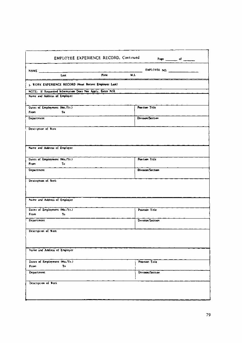
EMPLOYEE EXPERIENCE RECORD, Continued Pm of
NAME EMPLOYEE NO.
Uit Pint M.I.
5. WORK EXPERIENCE RECORD (Most Recent Employer Lut)
NOTE: If RequestedName and Address o{
Datei oi EmploymentFrom
Information Does Not Apply, Enter N/AEmployer
(Mo./Yr.)To
Department
Position Title
Division/Section
Description oi Wore
Name and Address oi
Dates oi EmploymentFrom
Employer
(Mo./Yr.)To
Department
Position Title
Division/Section
Description oi Vtark
Name and Address oi
Dates of EmploymentFrom
Employer
<Mo./Yr.)To
Department
Position Title
Div ision/Sectran
Description oi Work
Name and Address oi
Dates oi EmploymentFrom
Employer
(Mo./Yr.)To
Department
Position Title
Division/Section
Description of Work
79
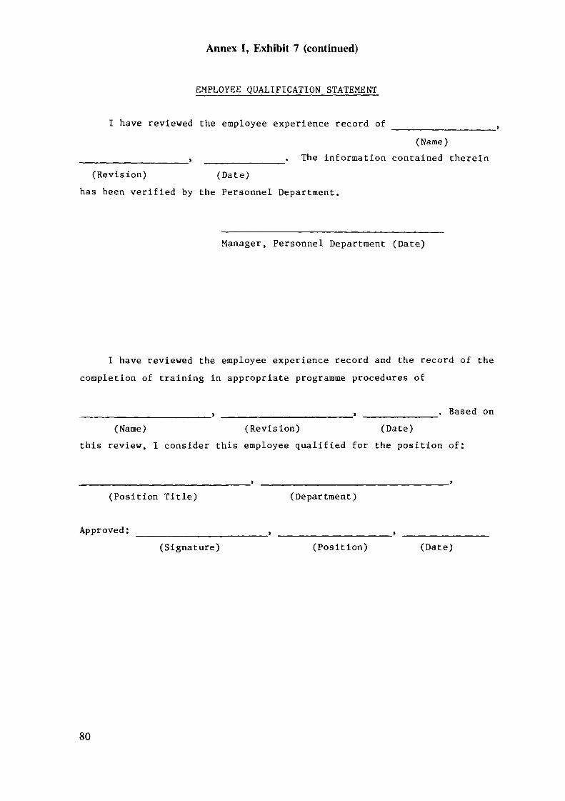
Annex I, Exhibit 7 (continued)
EMPLOYEE QUALIFICATION STATEMENT
I have reviewed the employee experience record of(Name)
The information contained therein(Revision) (Date)
has been verified by the Personnel Department.
Manager, Personnel Department (Date)
I have reviewed the employee experience record and the record of thecompletion of training in appropriate programme procedures of
, . . Based on(Name) (Revision) (Date)
this review, I consider this employee qualified for the position of:
(Position Title) (Department)
Approved: ___________________, ____________(Signature) (Position) (Date)
80

Annex I, Exhibit 8EXAMPLES OF TRAINING REQUIREMENTS AND RECORDS
(cited in para. 5.3)
EMPLOYEE QUALIFICATION STATEMENT
I have reviewed the employee Position Specification, verification ofeducation and experience memorandum from the Personnel Manager, and thecompleted Indoctrination and Training Plan of
(Employee Name) (Employee No.)
Based on this review, I certify this employee qualified to perform workfor the position of:
(position)
and qualified for the job of:
(Technical Department)
Approved: _____________________ _____(signature) (position) (date)
NOTE: This form to be prepared by the Responsible Manager andapproved by the next higher manager (e.g. Technical DepartmentManager/Project Manager).
81

Annex I, Exhibit 8 (continued)
NEW EMPLOYEE INDOCTRINATION AND TRAINING PLAN
Employee's NameDepartment __Employee's Manager
Employee No.
Indoctrination andTraining Subject
(1) Review ofproject
role in the
(2) Review of firms organizationalstructure and associatedresponsibilities
(3) Review of employee's specificresponsibilities as defined in his/herposition description
(4) Introduction to key firm and projectpersonnel
(5) Quality assurance program overview(6) Assignment of required reading
(responsible manager shallidentify appropriate documents)a.b.c.d.e.
Instructor/Responsibility
Manager
Manager
Manager
Manager
QA Manager
DateCompletion CompletionSignoff
(7) Special Training requirements for job(e.g.logging of borehole.hydrologicaltesting etc.)
82

Annex I, Exhibit 8 (continued)
NEW EMPLOYEE INDOCTRINATION AND TRAINING PLAN (continued)
Indoctrination andTraining Subject
Instructor/Responsibility
DateCompletion
CompletionSignoff,
( 8) Review of all QA program proceduresapplicable to the performance of his/her assigned tasks. (Responsible manageror training coordinator shall identifythe specific procedures applicable tothe individual's assignment.)
Manageror
TrainingCoordinator
a.b.c.d.e.Examination (exams may be given todemonstrate and document the individualsknowledge of the material presented,when deemed appropriate)
Manager
TRAINING SATISFACTORILY COMPLETED
Responsible Manager Date
83

Annex I, Exhibit 9aEXAMPLE OF THE REVIEW COMMITTEE MEETING
NOTICE FORM(cited in paras 5.5 and 6.7.5)
Review Committee Meeting Notice
1. Purpose of Meeting
2. Meeting ScheduleLocation ______Time ______Date
3. ParticipantsA. Review Board Members
Name Organization Area of Emphasis
(Chairperson)
(Secretary)
84

B. Other Invited ParticipantsName Organization Area of Emphasis
C. Project Team MembersName Title - Project Area of Responsibility
Manager or Designer
________________ QA Manager______ __________________
4. Content of Review Packageo Sample Review Questionso Title and Revision Number of Documents to be Reviewed
o Title and Revision Number of Calculations to be Reviewed
85

o Title and Revision Number of Drawings to be Reviewed
o Other Documents
o Design Criteria Documents for Design Being Reviewed
o Design Requirements for Which Material Has Been Prepared
o Licensing Requirements for Material to be Reviewed
86

o Status Action Items
If you have any questions, contact
Project Manager (Telephone Number)
87

Annex I, Exhibit 9bEXAMPLE OF REVIEW COMMITTEE REPORT FORM
(cited in para 6.7.5)
Page No.
REVIEW AND COMMENT FORM
To:From: Date
Project Document Title Doc. Date Revision No
Manager Originator - Siting Review Committee Requested CompletionDate:
Document intended Usage:
Section of Document to be Reviewed:
Page &Line No.Review Comments Comment Disposition
Reviewer Signature
Date:
Comment Dispositioner'sSignature____________Date:
88

I Page No.
REVIEW AND COMMENT FORM CONTINUATION SHEET
Project
Page &Line No.
Document Title
Review Comment
Reviewer Signature
Date:
Doc. Date Revision No.
Comment Disposition
Comment Dispositioner ' s Signature
Date:
89

Annex I, Exhibit 10EXAMPLE OF SAMPLE SHIPMENT FORM
(cited in para. 6.5.1)
Sample Identif ication
Sample Type_
Sample Identification
Total Number of SamplesDate Shipped _________________ Date Received
Handling Instructions
Special PackingStorage RequirementsTesting Program ___
90

Annex I, Exhibit 11EXAMPLE OF SAMPLE RECEIPT FORM
(cited in para. 6.5.1)
Sample Receipt
(Received By)
(Company Name)
(Street)
City & Country)
(Title)
(Telephone Number)
Description of Sample Condition
Acknowledgment of Receipt of Samples
Name and address to whom acknowledgment of sample receipt should be sent:
Date SentTelephone No.By ______
91

Annex I, Exhibit 12EXAMPLE OF DOCUMENT REVIEW FORM
(cited in para. 6.7.1)
DOC'JN"-NT REVIEW
Route To . . . Protect Manager_. Department Manager_ QA Speculi«. TAD Manager.. Ither
Contractor Name
Document Title
Contract No
Date OriginatedOriginated By
D No AttachmentD Attachment
Proi»ct ln»olvad anc|
Doc Date Re« No
ACCEPTED D As Is D With Conditions D NOT ACCEPTEDComments
Accepted By (Project f/gr I Date Approved By (Dept Manager) Date
CONCURRENCE D As Is D With Conditions D NO CONCURRENCEComment!
Concurrence IQAD Specialist) Date Approved By (QAD Manag«) Date
Dutribution of this form made
By Title Date
Distribution of copies viien corpleted:white - Project Files; pink - Contract Special: blue - QAD ManagerQAD Files; yellow - Quality Assurance Specialist; green - Project Manager.
92

Annex I, Exhibit 13EXAMPLE OF NON-CONFORMANCE REPORTING FORM
(cited in para. 6.8)
NONCONFORMANCE REPORT(Se* remw )idt for initructiom)
1)NR NO.
2) DATE
ITEM IDENTIFICATION AND DESCRIPTION
4) PROJECT 5) CONTRACT NO. 6)DEPARTMENT OR CONTRACTOR
0 SPECIFICATION NO. AND REVISION 8) DRAWING NO. AND REVISION
DESCRIPTION OF NONCONFORMANCE
A. ACTUAL CONDITION B. REQUIREMENT
10) ISSUED BY (ÜA SPECIALIST) DATE APPROVED BY (OAD MANAGER) DATE
DISPOSITION
G ACCEPT O REJECT 0 REWORK/REPAIR
JUSTIFICATION AND SPECIAL REQUIREMENTS
O CONDITIONAL (EXPLAIN)
DISPOSITION APPROVALS
PROJECT MANAGER DATE DEPARTMENT MANAGER DATE QAD MANAGER DATE
M) QAD VERIFICATION D REQUIRED - LIST ACTION AND RESULTS D NOT REQUIRED
QAD SIGNATURE . DATE
F mil Distribution QAD Mcnigtr. PralMt OHic» Mtnigor. D*p«rtnMnt Mwugor. Pra|*et M«n*«>r. QA S**c»4»t.Project F««. QAO FM«. Copy to /
93

NONCONFORMANCE REPORT INSTRUCTIONS(PleaM Print or Type)
QA SPECIALIST
1 NR No2. DIM3 I Urn Identification and Description
4 Project5 Contrée» No6 Department or Contractor7 SptaficjJxxr No and Revision
8 Drawing No and Rivuion9 Description of Nonconfot mance
A. Actual ConditionB Requirement
10 Issued
• Obtain number from QAD Coordinator• Enter upon origination data• Oatcnb* itam (iudi n itam nama, tiza, function - a g , ' 3 inch
hex h.ad bolt". "200 Ibl catt itaal A216 77, Grada WCA")• En tar nama of project• Entar contract number• Entar nama of dapartmant or nama of contractor• Entar applicable «pacification nama, including number andrevision
• Enter applicable drawing number and revision
• Describe the nonconformmg condition• State the requirement to which the actual condition did notcomplySignature of QA Speaalut u required
QAD MANAGE R
11 Approved - Signature of QAD Menacer n required
REPONSIBLE PROJECT MANAGER. DEPARTMENT MANAGER AND QAD MANAGER
12 Dlipotition13 Diipotition Approval!
— Detcnbe disposition, justification and any spécial requirement!- Signature! of responsible project manager, department manager
ind QAD manager required
QA SPECIALIST
14 Q^D Verif icaion — Indicate if verification actions are required, if required indicatewhit actions were performed, when and if these actions wereacceptable Signature of QA specialist or QAD managerrequired
94
ANNEX II:
EXAMPLES OF PROCEDURES OR WORK INSTRUCTIONSFOR VARIOUS SITING ACTIVITIES
95

Annex II, Exhibit 1EXAMPLE OF WORK PROCEDURE FOR SPECIFIC ACTIVITY
(cited in para. 4.5)
PROCEDURE FOR EVALUATION OF DESIGN BASIS TSUNAMI
Objective:
Evaluation of the design basis tsunami at the site in combinationwith other adverse coastal hydrological conditions. Based on thisevaluation a design plant grade ensured of no coastal flooding shall beestablished.
Scope;
Earthquakes with M > 6 which have occurred in the following offshoreregion shall be considered: x __________________________________
Earthquakes with M > 6 which have occurred in the following timeperiod shall be considered: x ________________________________
The far field bathymetry maps shall have a scale, not smaller than: x
The near field bathymetry maps shall have a scale, not smaller than:x
All records of tsunami in the following regions shall be compiledfrom literature: x ___________________________________________
All records of tsunami in the following regions shall be compiledfrom literature as well as original sources: x ___________________
Note: x information to be provided for each specific project.
All computer programmes used shall have appropriate verification.
97

Procedure
(1) All available tsunami and earthquake catalogues for the definedregions and time periods shall be searched and a list of alltsunamigenic events and tsunami observations shall be compiled in a"project tsunami catalogue". Procedures applicable to thecompilation of historical earthquake data shall be followed in thepreparation of this catalogue.
(2) A model of all tsunamigenic sources shall be established andappropriate and substantiated source parameters shall be assigned.
(3) The sea bottom, coastline and islands relevant to the travel path(from source to site) shall be defined in sufficient detail (seescope for appropriate scales).
(4) The mathematical model and the numerical method employed shall beadequately substantiated.
(5) Computer programmes used in the evaluation shall be verified.
(6) Analytical results shall be checked against possible observationsand differences shall be explained.
(7) A design tsunami height shall be established, running and draw-downvalues shall be calculated.
(8) This value shall be considered in the context of other possibleadverse coastal hydrological conditions and a design height (i.e.plant grade) for coastal flooding shall be established.
98

Annex II, Exhibit 2EXAMPLE OF WORK PROCEDURE FOR SPECIFIC ACTIVITY
(cited in para. 4.5)
FIELD DETERMINATIONS OF WATER LEVELSIN OBSERVATION WELLS AND PIEZOMETERS
Purpose
This procedure describes the methods for the accurate determinationof water levels in observation wells and piezometers.
This procedure describes the use of the weighted tape, the wettedtape, the electric sounder, and continues water level recorders for waterlevel measurements. Responsibilities and required documentation arediscussed.
Responsibilities
The Field Hydrologist shall have overall responsibility for thehydrology field operations. He/she shall give written directions to theStaff Hydrologist as to the particular wells in which water levels are tobe determined, the frequency of measurements, and the type of apparatusto be used for such measurements.
Apparatus
All apparatus are subject to approval and modification by the FieldHydrologist. Equipment types are given below:
Weighted Tape: The weighted tape apparatus consists of a calibrated,steel tape with a weight attached. An identificationnumber shall be attached to the tape and recorded onthe data sheet.
99
Wetted Tape: A lead weight is attached to a calibrated steelmeasuring tape. The lower three feet of the tapeshall be dry and coated with carpenters chalk. Anidentification number shall be attached to thetape and recorded on the data sheet.
Electric Sounder: The electric sounder shall consist of a contactelectrode, a two-wire cable, a steel tape, anammeter, and a reel. The sounder shall have anidentification number attached and that numbershall be recorded on the data sheet.
Water Level Recorders: For continuous measurements, a water levelrecorder shall be utilized.
Pressure Gauge: The pressure gauge measures pounds per squareinch on a shut-in free flowing well. The pressuregauge shall have pipe fittings and shall beequipped with an air-release valve attached toits stem to allow connection to the well headfittings. The gauge shall have an identificationnumber and calibration record.
Precedural Steps:
Weighted Tape: The weighted tape shall not be used to measurewater levels unless the water level in the wellis visible from the surface. The weighted tape islowered down the well until the weight is incontact with the water surface. The depth fromthe top of the well casing to the water surfaceis then read directly from the tape to thecentimeter, and recorded as the depth to thewater level. If the weight extends beyond the endof the tape, the readings must be corrected toallow for this condition.
100
Wetted Tape: If the approximate depth of water is known, thetape is lowered into the well until a part of thechalked portion of the tape is below water. Oneof the meter marks is held exactly at the edge ofthe well casing. The tape is raised and read to acentimeter on the wetted portion of the chalkedtape. The difference between this reading and themeter mark of the measuring point is the actualdepth to water level.
If the approximate depth to the water is notknown, a trial and error procedure of loweringthe chalked tape into the well will give anindication of the depth. The steel tape shouldalways be dried before applying chalk.
Electric Sounder: The contact electrode shall be attached to thetwo-wire cable, with excess cable placed on areel. The other end of the two-wire cable shallbe connected to an ammeter, legs may be attachedto the reel, especially if it is a large size. Asteel tape may be attached to the cable formeasurements.
The electrode is lowered slowly into the well andthe ammeter is observed. The needle of theammeter will deflect when contact is made withwater because of the closed circuit provided bythe water. After the needle first deflects, thecable and steel tape should be raised severalinches and then slowly lowered until the needledeflects again. The steel tape shall then be readto the nearest centimeters.
101

Water Level Recorders: A Leoupold and Stevens Type F (model 68) waterlevel recorder shall be used. This apparatusconsists of a recorder with protective casing,float pulley, spring-driven clock, beaded steelline, a float, and weight.
Those wells in which water level recorders are tobe installed shall have an extended casing ofapproximately 1 meter above ground level. Theminimum casing diameter shall be 10 cm.
The float and weight shall be attached to thebeaded steel line and placed on the pulley. Therecorder must be positioned so that the float,weight and line will align within the casingwithout drag against the well casing. If anapproximate range in water level fluctuations isknown, the length of line to be used in order tokeep the weight above the water surface is easilydetermined. Any excess line shall be wrappedaround the line that leads to the float and notcut.
After the water level recorders have beenproperly installed to depth to the water surfaceis measured by any valid method. The float isthen lowered into the well to the water level,and the stylus is moved to the left edge of thegraph paper. This position is marked on the graphpaper as "initial water level reading", inmeters, along with the time of the reading.Subsequent readings may then be made directlyfrom the graph paper.
102
The following items shall be checked or performedbefore complete installation is made:
1. Check that the stylus contains proper level ofink and that the ink is flowing.
2. Ensure that the lock which turns the styluscarriage is completely wound.
3. Check that the graph paper is clean and intact.
4. The instrument cover must be placed on therecorder to protect against dust, weather, andinsects.
The recorder shall be periodically monitored toensure records are being maintained on therecorder drum. The recorder shall be placedwithin a protective steel box, firmly affixed tothe well casing, and locked.
Pressure Gauge: The well head casing stick-up is tapped with asmall gate valve and pipe fittings and shouldextend horizontally for the attachment of thepressure gauge. The pressure gauge shall have anair-release valve attached to the connectingstem. After the pressure gauge is attached to thewell and the gate valve opened, the air-releasevalve shall be bled to release any gas that mayhave accumulated in the gauge and stem. Thepressure gauge is then read in psi, which ismultiplied by a value of 2.31 to convert thereading to feet.
103
Documentation
The well number, water level reading, the time of the reading, thename of the person making the reading, and the type of apparatus used,the air temperature, and weather conditions shall be noted on a DailyWater Level Reading Form. Documentation on this sheet shall also includethe elevation of the datum and a description of the datum (e.g. groundsurface, top of casing).
Data obtained from water level recorders shall include the recordergraph paper and a data sheet. Data to be logged on the recorder graphpaper shall be: recorder identification number, initial water levelreading and time of the reading, correlative water level reading shown onrecorder and time of the reading, a11 dates of water level readings,boring number, and person(s) making such measurements.
104
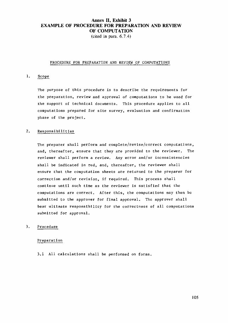
Annex II, Exhibit 3EXAMPLE OF PROCEDURE FOR PREPARATION AND REVIEW
OF COMPUTATION(cited in para. 6.7.4)
PROCEDURE FOR PREPARATION AND REVIEW OF COMPUTATIONS
1.
The purpose of this procedure is to describe the requirements forthe preparation, review and approval of computations to be used forthe support of technical documents. This procedure applies to allcomputations prepared for site survey, evaluation and confirmationphase of the project.
2. Responsibilities
The préparer shall perform and complete/revise/correct computations,and, thereafter, ensure that they are provided to the reviewer. Thereviewer shall perform a review. Any error and/or inconsistenciesshall be indicated in red, and, thereafter, the reviewer shallensure that the computation sheets are returned to the préparer forcorrection and/or revision, if required. This process shallcontinue until such time as the reviewer is satisfied that thecomputations are correct. After this, the computations may then besubmitted to the approver for final approval. The approver shallbear ultimate responsibility for the correctness of all computationssubmitted for approval.
3. Procedure
Preparation
3.1 All calculations shall be performed on forms,
105

3.2 Calculations shall state the following: purpose, input data(including units), analytical procedure being used, andspecific reference to the procedure being used.
3.3 Units of measurement (both fundamental and derived) should begiven in the International System of Units (SI units).Calulations should be performed in SI units. It is preferredthat the results of such calculations be expressed in SI unitsand in imperial units (in parentheses). In cases where commonindustrial usage is not in SI units, and where SI units wouldbe confusing (e.g. discipline specific units), the resultsshould be given in the commonly accepted units.
3.4 Significant figures are important in evaluating the accuracy ofa measurement or calculation. When converting from one systemof units to another, or rounding off decimal values, careshould be taken to observe the elementary principles used inassigning the correct number of significant figures.
3.5 The computations shall be presented in a clear and concise formso that each step may be individually checked and verified.Flowcharts shall be supplied if regarded as necessary for anunderstanding of the computations.
3.6 The reviewer shall clearly state on the first page of thecalculations, in the appropriate blank, the type of reviewperformed which may consist of any one of the following: areview of the input data and analytical procedures used, spotchecking of selected computations, or complete review of allcomputations. All items checked by the reviewer and verifiedas being correct shall be indicated with a check mark. Allquestions and corrections shall be indicated in red, the errorsindicated if possible, and the calculations then returned tothe préparer.
106

3.7 The préparer shall resolve the questions and make necessarycorrections. All corrections must be signed by the préparerand dated on the sheet where they are corrected. When thesehave been made, the computation sheet shall be returned to thereviewer for review. Agreement shall be indicated by writing"agree" next to the resolved question and correction items.Revisions to the computations shall also be made following thisprocedure.
3.8 Copies of the computation sheets shall be retained in theProject Files.
107
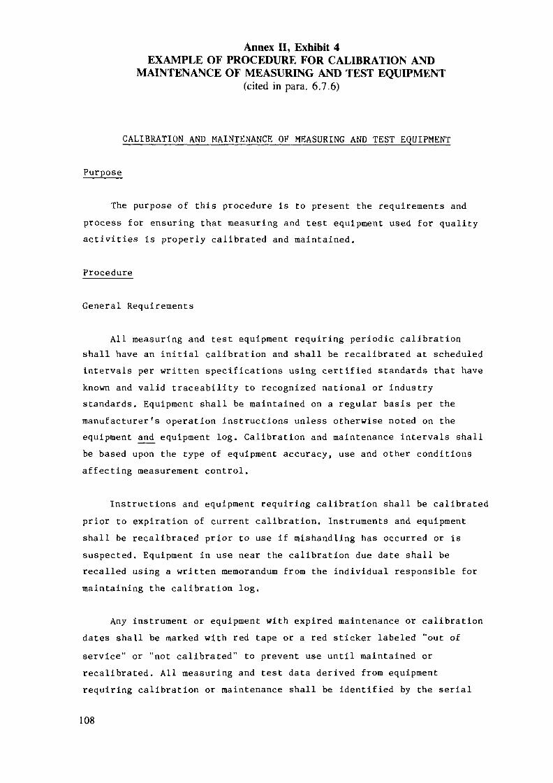
Annex II, Exhibit 4EXAMPLE OF PROCEDURE FOR CALIBRATION AND
MAINTENANCE OF MEASURING AND TEST EQUIPMENT(cited in para. 6.7.6)
CALIBRATION AND MAINTENANCE OF MEASURING AND TEST EQUIPMENT
Purpose
The purpose of this procedure is to present the requirements andprocess for ensuring that measuring and test equipment used for qualityactivities is properly calibrated and maintained.
Procedure
General Requirements
All measuring and test equipment requiring periodic calibrationshall have an initial calibration and shall be recalibrated at scheduledintervals per written specifications using certified standards that haveknown and valid traceability to recognized national or industrystandards. Equipment shall be maintained on a regular basis per themanufacturer's operation instructions unless otherwise noted on theequipment and equipment log. Calibration and maintenance intervals shallbe based upon the type of equipment accuracy, use and other conditionsaffecting measurement control.
Instructions and equipment requiring calibration shall be calibratedprior to expiration of current calibration. Instruments and equipmentshall be recalibrated prior to use if mishandling has occurred or issuspected. Equipment in use near the calibration due date shall berecalled using a written memorandum from the individual responsible formaintaining the calibration log.
Any instrument or equipment with expired maintenance or calibrationdates shall be marked with red tape or a red sticker labeled "out ofservice" or "not calibrated" to prevent use until maintained orrecalibrated. All measuring and test data derived from equipmentrequiring calibration or maintenance shall be identified by the serial
108

number of the equipment used to perform that measurement or test. If theequipment has no serial number, a unique serial number shall be assigned.
If nonconforming equipment is identified, the equipment shall besegregated or tagged, a nonconformance or incident report (as applicable)shall be written and an analysis of the data obtained during the"out-of-calibration" or "non-maintained" status shall be performed by theresponsible Task Leader and Quality Assurance personnel to determine thevalidity and usefulness of the data which shall be reported to theProject Manager.
Measuring and test equipment shall be used for their intendedpurpose and shall be stored according to the manufacturer'srecommendations when not in use. All measuring and test equipment shallbe protected from dust and contamination, shall be visually checked fordecage prior to use, and shall be oiled, lubricated, and/or maintained ona regular basis per the manufacturer's instructions.
During shipping, measuring, and test equipment shall be adequatelypackaged to prevent damage from jarring, shock, or vibration. Instrumentsthat are sensitive to temperature change shall be properly insulated.
Documentation demonstrating compliance with this procedure shall bemaintained in accordance with approved procedures for Quality RelatedRecords.
109

Annex II, Exhibit 5EXAMPLE OF LABELS TO BE PLACED ON MEASURING
AND TEST EQUIPMENT(cited in para. 6.7.6)
CALIBRATION DUE
DATE
THIS ITEM LAST CALIBRATEDDATE BY (STAMP)
NOT CALIBRATED
NOT TO BE USED
FOR OFFICIALMEASUREMENT PURPOSES
OUT OF SERVICE
MUST BE REPAIREDAND/OR CALIBRATED
BEFORE USE
NAME DATE
110

FIELD EQUIPMENT CALIBRATION RECORD0'
PROJECT NAME____________________ DATE____PROJECT NUMBER'_______________ PERSONNEL.
EQUIPMENT IDENTIFICATIONEQUIPMENT NAME _______REQUIRED CALIBRATION PERIOD.
CALIBRATION TECHNIQUE*21.
REMARKS
NOTES (I) THIS RECORD SHALL BE COMPLETED POP ALL EQUIPMENT CALIBRATED INTHE FIELD.
(2) IF APPLICABLE, CITE REFERENCE TO QUALITY ASSURANCEMANUAL.
I l l

CALIBRATION / SERVICE SPECIFICATIONITEM NAME
MANUFACTURER
MODEL SERIAL No.
PROJECT
MANU F. LOG AT I ON
SPEC.. NO.
DATEPURCHASED
APPROVED
CALIBRATION REQUIREMENTSSOURCE MAXIMUM INTERVAL
GENERAL DESCRIPTION & OPERATING REQUIREMENTS
ENVIRONMENTAL CONDITIONS
CHARACTERISTIC / RANGE TOLERANCE CONDITION / LIMITATION
SERVICE REQUIREMENTS
TAMPER-PROOF SEALING REQUIRED 0 NOT REQUIRED Q
PREVENTATIVE MAINTENANCE
OPERATIONAL TEST
S I G N E D :
DATE:
112

ANNEX III:
EXAMPLE OF DESCRIPTION OF QA ACTIVITIESFOR NUCLEAR POWER PLANT SITING
IN FRANCE
113

ASSURANCE DE LA QUALITE POUR LE CHOIX D'UN SITEDE CENTRALE NUCLEAIRE PAR ELECTRICITE DE FRANCE
1 - INTRODUCTION
La mise en oeuvre du programme nucléaire français lancé en 1974, par ELECTRICITE DEFRANCE (EDF), a nécessité l 'ouverture sur le territoire national, de 18 siteséquipés chacun, ou en cours d'équipement, de 2, 4 ou 6 unités de 900 MWe ou 1300MWe (1), du type PWR, et de deux sites équipés de réacteurs du type FBR. En 1986,45 unités ont déjà été couplées au réseau, 13 unités sont encore en construction.Deux nouveaux sites sont par ailleurs en préparation.
Les unités ont été standardisées par EDF afin de profiter au maximum de l 'e f fe t desérie, en ce qui concerne, notamment, la mise au point et la qualité des instal la-tions.
Le choix des sites est une opération délicate qui peut mettre en cause, si le cho ixn'est pas bon, la sécurité de l' installation future, sa f iabil i té de fonctionne-ment, voire l 'économie même du projet.
Pour toutes ces raisons, EDF a décidé de soumettre les actions conduisant au choixdu site, aux règles d 'Assurance de la Qual i té ( A . Q . ) ( 2 ) , au même titre que laconception, la construct ion et l 'explo i tat ion des centrales nucléaires.
L 'expér ience acquise par EDF en matière de choix de site lui permet aujourd'hui dedéfinir les modali tés et procédures qu'i l convient de suivre en vue d'obtenir laqualité requise, sans alourdir inutilement les études, mais sans omettre cependantdes études et des vérif ications jugées indispensables.
Après avoir rappelé le cadre réglementaire, et les parts prises par les di f férentsacteurs intervenant dans l 'A .Q. , une description rapide des différentes étapes duchoix d'un site et des critères qu'il convient de prendre en compte est présentée.
Les modalités et procédures d ' A . Q . appliquées à chacun de ces critères de choixsont ensuite décrites plus en détail dans la 3ème partie du présent document.
2 - PRINCIPES GENERAUX D'ASSURANCE DE LA QUALITE ( A . Q . )
2.1. Cadre réglementaire
Dans sa note d'orientation de juin 1973, reprise par celle du 3 janvier1984, révisée le 3 septembre 1986, EDF définit la doctrine de la Directionde l'Equipement en matière d'"Assurance de la Qualité pour l 'étude et laréalisation des ouvrages de production d'électricité" ( 3 ) .
(1) MWe : Mégawatts électriques(2) A .Q. : Assurance de la Qualité (dans tout le texte)(3) Cette note d'orientation de même que les autres documents cités dans la
présente note concernant l 'organisation de l 'A .Q . des dif férentesunités et organismes intervenant dans le choix des si tes, ne sont pasaccessibles. Ils ne peuvent être communiqués à l 'extérieur d 'EDF sansl 'accord du Directeur Technique de l'Equipement.
115

Cette doctrine qui s 'appuie sur les textes of f ic ie ls
- Les règles fondamentales de sûreté (RFS) édictées par le SCSIN (1) duMinistère de l'Industrie, dont celle référencée "V .Z .a " du 3 novembre1981 est relative à l ' A . Q . appl icable aux tranches nucléaires à eau souspression.
- L 'Arrêté ministériel du 10 août 1984 relatif à la qualité de la concep-tion, de la construction et de l 'exploi tat ion des instal lat ions nucléai-res de base.
- Le Code de bonne pratique (50 -C-QA) et les guides associés de 1 'A IEA.
est étendue au choix des sites de centrales nucléaires, conformément auxprincipes indiqués dans le présent rapport.
En particulier, les dif férentes opérations conduisant au choix du site, quipeuvent être la recherche de documentation, des études, des travaux dereconnaissance, ... sont soumises aux règles générales d 'A .Q . en vigueurpour la documentation, les études, les travaux, ... menés par la Directionde l 'Equipement, et déf inies dans les manuels d ' A . Q . de chaque unité de laDirection de l 'Equipement et dans ceux propres à chaque fournisseur ouintervenant, extérieurs à l 'établ issement.
2.2. Responsabi l i tés
La responsabil i té du choix des sites appartient à EDF, maître d 'ouv rage ,qui assure également la maîtrise d 'oeuvre en ce qui concerne la conceptionet la construction des centrales nucléaires.
A ce titre, EDF est responsable de 1 ' A . Q . dans ses propres Services ets 'assure que les fournisseurs, bureaux d'études, entrepreneurs intervenantpour l 'Etablissement , possèdent bien et mettent correctement en oeuvre uneA.Q. de leurs prestations respect ives.
En fonction de la nature des prestations, des Services de la DIRECTION DEL'EQUIPEMENT O 'E .D.F . spécialement chargé de l ' A . Q . , indépendants desServices opérationnels, s 'assurent que ces dispositions d 'A .Q . sont bienappliquées.
- le Service du Contrôle Externe des Etudes ( C . E . E . ) pour les études.
- le Département Topographie-Exécution-Géologie-Géotechnique (T .E .G .G . )pour les travaux sur le site, reconnaissances, etc...
De plus, conformément à la législat ion en vigueur en France et pour lesopérations concernant, notamment, la sécurité nucléaire, les Autoritésadministratives exercent un contrôle sur EDF et s 'assurent que l 'ensembledes disposit ions d 'A .Q . prévues sont, d'une part adéquat, d'autre parteffect ives et bien appliquées. Ces contrôles sont exercés sous l 'égide duSCSIN par un corps d'inspecteurs des "installations nucléaires de base"nommés par le Gouvernement.
Enfin, en ce qui concerne plus spécialement le choix des sites, l 'Etablis-sement est tenu, avant tout début de réalisation de la centrale, d'obtenir
(1) SCSIN : Service Central de Sûreté des Installations Nucléaires
116

les autorisations nécessaires dans le cadre des procédures administrativese x i s t a n t e s :
- déclaration d'utilité publique,- autorisation de création,- permis de construire,- etc... ;
el les prévoient un examen complet des dossiers par les Services des Admi-nistrations devant donner leur av is avant l 'ouverture de l 'enquêted'util ité publique qui étend la concertation à l 'ensemble de la populationconcernée. Ces procédures constituent, en fai t , le dernier maillon de1 ' A . Q . du choix des s i tes à l ' i ssu duquel le choix est, ou n'est pas,confirmé.
La procédure d'autorisation de création repose sur une analyse complète dela sûreté du projet. Avant de donner leur avis, les Services responsablesde l 'Administrat ion consultent leurs appuis techniques (Institut de Protec-tion et de Sûreté Nucléaire du CEA) ainsi qu'un groupe d'experts indépen-dants. Le décret d'autorisation de création est signé par le premierMinistre après avis de la Commission interministérielle des Installationsnucléaires de base, et avis conforme du Ministre de la Santé. A toutes lesétapes de l ' instruct ion de cette procédure, la conformité des travaux auprogramme d ' A . Q . est contrôlée.
2.3. Principes généraux d 'A .Q. retenus
Les principes généraux d ' A . Q . retenus par EDF, sont définis par la note dedoctrine de la Direction de l'Equipement du 3 janvier 1984 révisée le3 septembre 1986, "AQ pour l'étude et la réal isat ion des ouvrages deproduction d'électr icité", étendue au choix des si tes.
Pour une prestation donnée, quelle que soit la nature de celle-ci (études,travaux sur site ...) et quel que soit l 'exécutant (EDF lui-même, bureauextérieur ...), les principes fixent les disposit ions d ' A Q prises, avec 3niveaux d 'act ions :
- exécution et contrôles associées,- véri f icat ion technique,- véri f icat ion de l 'appl icat ion du programme d 'AQ
dans le cadre de l 'object i f d 'AQ recherché que l ' on peut résumer commesuit : bien définir la qualité requise, obtenir la qualité définie, véri-fier que la qualité définie a été obtenue, corriger les défauts éventuels,et pouvoir enfin démontrer que la qualité requise a été obtenue et véri-fiée. Ce dernier point implique la formalisation, par écrit, de toutes lesactions d ' A . Q . et l 'archivage des documents correspondants.
Sauf exception justi f iée, toutes les études intéressant la sûreté sontvérifiées, en fonction de leur importance pour la sûreté, par des personnesindépendantes de celles qui ont réalisé les études.
Néanmoins, pour les documents d'études, dits "de pratique industriellecourante", ou si l 'expérience acquise a déjà permis de valider les procédésou les codes utilisés, les études peuvent alors n 'être soumises qu'à laseule vérif ication technique effectuée sous l 'autorité hiérarchique.
Les principes d 'AQ retenus sont conformes aux recommandations de 1 'AIEA, etrespectent les directives f ixées par la législation française.
117
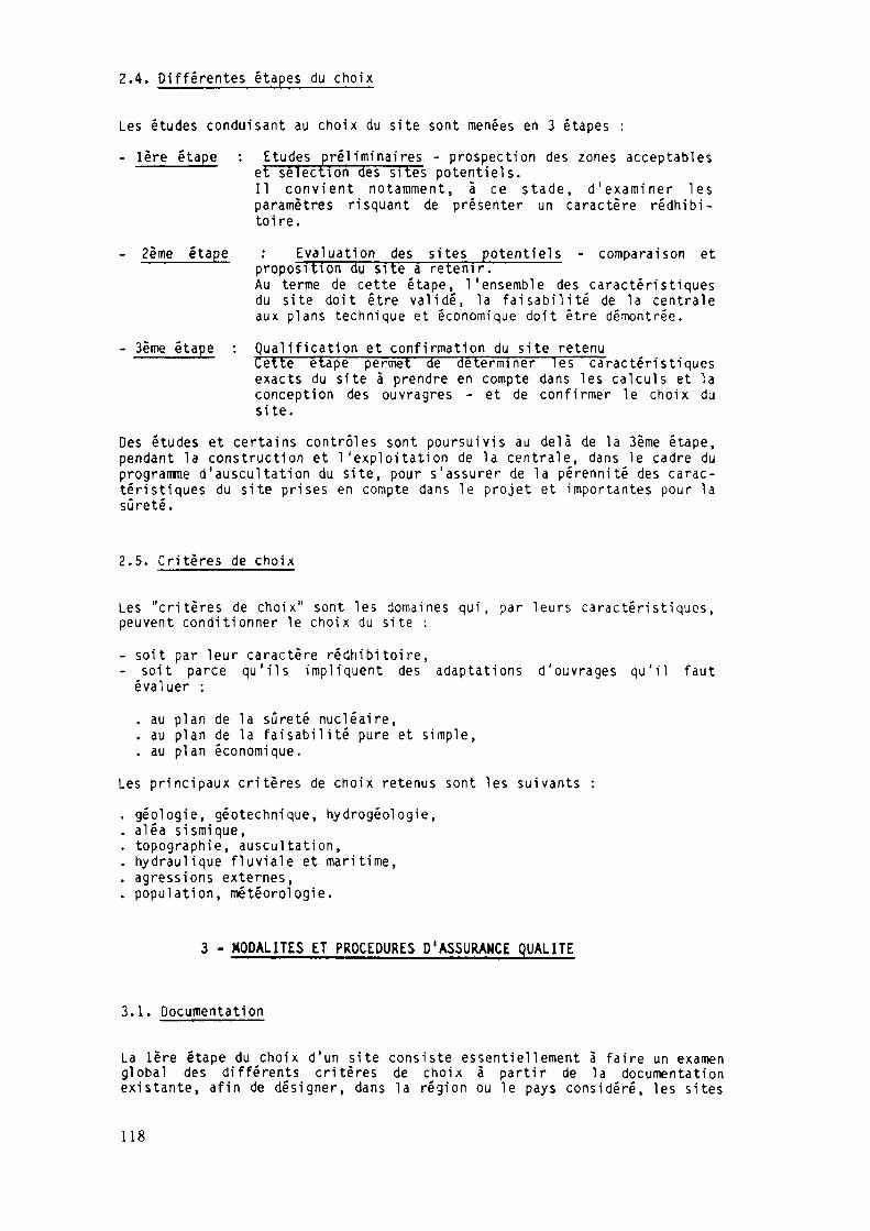
2.4. Différentes étapes du choix
Les études conduisant au choix du site sont menées en 3 étapes :
- 1ère étape : Etudes pré!iminaires - prospection des zones acceptableset sélection des sites potentiels.Il conv ient notamment, à ce s tade, d ' e x a m i n e r lesparamètres risquant de présenter un caractère rédhibi-toire.
- 2ème étape : Evaluation des sites potentiels - comparaison etproposition du site a retenir.Au terme de cette étape, l 'ensemble des caractérist iquesdu site doit être val idé, la fa isab i l i té de la centraleaux plans technique et économique doit être démontrée.
- 3ème étape : Qual i f icat ion et confirmation du site retenuCette étape permet 3"êdéterminer HTscaractér is t iquesexacts du site à prendre en compte dans les calculs et laconception des ouvragres - et de confirmer le choix dusite.
Des études et certains contrôles sont poursuivis au delà de la Sème étape,pendant la construction et l 'explo i tat ion de la centrale, dans le cadre duprogramme d'auscultat ion du site, pour s 'assurer de la pérennité des carac-téristiques du site prises en compte dans le projet et importantes pour lasûreté.
2.5. Critères de choix
Les "cri tères de choix" sont les domaines qui, par leurs caractér is t iques,peuvent conditionner le choix du site :
- soit par leur caractère rédhibitoire,- soit parce qu' i ls impliquent des adaptat ions d 'ouvrages qu'i l faut
évaluer :
. au plan de la sûreté nucléaire,
. au plan de la faisabi l i té pure et simple,
. au plan économique.
Les principaux critères de choix retenus sont les suivants :
. géologie, géotechnique, hydrogéologie,
. aléa sismique,
. topographie, auscultat ion,
. hydraulique f luviale et maritime,
. agressions externes,
. population, météorologie.
3 - MODALITES ET PROCEDURES D'ASSURANCE QUALITE
3.1. Documentation
La 1ère étape du choix d'un site consiste essentiellement à faire un examenglobal des différents critères de choix à partir de la documentationexistante, afin de désigner, dans la région ou le pays considéré, les si tes
118

potentiellement réalisables et, par là, d'éliminer ceux pour lesquels un ouplusieurs critères de choix présenterait un caractère rédhibitoire.
Si la documentation existante est incomplète sur certains points, oucomporte des erreurs, des recherches complémentaires voire des investiga-tions sur le terrain peuvent être engagées. Ce n'est généralement pas le casen France où l 'on dispose déjà de données historiques très complètes,émanant d'organismes nationaux spécial isés et hautement qualifiés.
Ces documents sont ensuite complétés, interprétés, synthétisés ... au tra-vers des 3 étapes du choix du site. Les documents les plus généralementutil isés sont les suivants :
Cartes géographiques et vues aériennces
Ces documents sont établis et fournis par l'Institut GéographiqueNational { I .G.N.) jusqu'à l 'échelle 1/25 OOOème pour les cartes, etl 'échel le de 1/43 OOOème en général pour les vues aériennes. L' I .G.N.garantit la qualité de ses prestations.
La validité de ces documents, et notamment leur validité au moment del 'ut i l isation est éventuellement vérifiée sur le terrain. Si une mise àjour ou des levés complémentaires sont nécessaires, ceux-ci sontréal isés soit directement par la Division Topographie de la Directionde l'Equipement d'E.D.F., soit, confiés à des bureaux extérieurs (c f .3.4) . De même, d'autres couvertures aériennes peuvent être effectuéespour actualiser cel les existantes et compléter les cartes. En France,un exemplaire de toute nouvelle carte réalisée est obligatoirementtransmis à 1'1.G.N.
Cartes marines et données marines
Elles proviennent du Service Hydrographique de la Marine Nationale quipeut préciser les dates d'établissement ou de mesures, ainsi que lesdernières mises à jour effectuées ; le Service Hydrographique de laMarine Nationale a ses propres règles d 'A .Q. placées sous la responsa-bilité des Ingénieurs en chefs hydrographes.
Dans le cas où des données plus spécifiques sont nécessaires, leLaboratoire National ^d'Hydraulique de la Direction des Etudes etRecherches d'EDF est à même de réaliser ses propres mesures qui sontalors soumises à son programme spécifique d 'A . Q.
Autres données
Les autres données qui s'avèrent nécessaires sont, pour la plupart,obtenues auprès des grands services Ministériels Français ; ce sont,par exemple :
- l 'armée de l 'air pour les données relatives à l'aviation militaire,
- le Ministère de l'Urbanisme, du Logement et des Transports, leMinistère de l'Intérieur, les Préfectures maritimes et la SociétéNationale des Chemins de Fer Français pour les transports par voiesd'eau, par route et par rail,
- le Ministère de l'Environnement,
- l'Institut National de la Statistique (INSEE) pour les populations,
119

- les Agences de Bassin pour les Fleuves, données hydrologiques ...,
- le Bureau de Recherche Géologique et Minière (B .R.G.M. ) , le Servicedes Mines et l'Institut de Physique du globe pour la géologie et lesséismes,
- le Ministère de l'Industrie et les Directions Régionales pour lesindustries à risques potentiels,
- la Météorogie Nationale.
Si ces données nécessitent d'être complétées, vér i f iées ou transformées,que ces opérations soient effectuées par E.D.F. ou par des organismesspécia l isés extérieurs à l 'Etablissement, el les sont soumises aux règlesd 'A .Q. de ceux qui réalisent le travail.
3.2. Géologie - Géotechnique - Hydrogéologie
L'étude de la géologie des sites qui conditionne le projet et la tenueultérieure dans le temps des installations commence dès les premièresinvestigations régionales. La connaissance est ensuite peu à peu a f f inée aufur et à mesure de l 'avancement des études de site.
En France, la règle fondamentale de sûreté I.3.c. "Etudes géologique etgéotechnique du site ; détermination des caractéristiques des sols etétudes du comportement des terrains" s'applique aux sites des centralesnucléaires à eau sous pression. Les reconnaissances, les moyens d'étude descaractéristiques géologiques et mécaniques des terrains, les essais in situou en laboratoire sont adaptés à chaque cas.
Les 3 étapes des études de géologie, de géotechnique et d'hydrogéologie(c f . 2 .4 ) correspondent à trois niveaux d'études de plus en plus précis,sanctionnés par trois avis :
- avis A pour la première étape,- avis B pour la deuxième étape,- avis C pour la troisième étape.
Dans ces discipl ines, les études sont effectuées, tout ou partie, par laDivis ion Géologie-Géotechnique du département T . E . G . G . ( O . G . G . ) , dontl 'organisat ion et les procédures de qualité sont décrites dans le manueld 'A .Q . du Service Central de la DIRECTION DE L'EQUIPEMENT D 'E .D .F .
3.2.1. Av is A
L'av is A est établi sans engagement de travaux sur le site sur la base dedonnées existantes après une visi te de terrain par un géologue confirmé,possédant une bonne connaissance des installations à construire.
Il permet de vérif ier que le site ne présente pas de défauts rédhibitoirespour la faisabilité du projet et de proposer une orientation des études etreconnaissances nécessaires à^ la définition des conditions de cettefaisabilité dans les étapes ultérieures des études.
Les données existantes sont constituées par les cartes géologiques, lescartes sismotectoniques, les documents bibliographiques, les publicationsd'études d'organismes spécialisés, les photos aériennes et de satellites,etc... et, bien entendu, les résul tats de sondages éventue lspré-exi stants.
120

Les études comprennent :
- d'une part, une vérification de la cohérence et de la validité desdonnées recensées,
- d'autre part, l'analyse et la synthèse des données qui permettentd'étayer l 'av is formule.
Ces études sont conduites par O.G.G. dans le cadre des disposit ionsdéfinies par le manuel d 'A .Q . du Service Central de la DIRECTION DEL'EQUIPEMENT.
3.2.2. Avis B
L 'av is B repose sur l 'acquisi t ion de nouvelles données à partir del 'exécution de travaux de reconnaissances sur le site, complétée par desessais en laboratoire. Il définit les conditions générales de fondation etd'environnement hydrogéologique du site qui permettent de conclure à safaisabilité, identifie les paramètres qui restent à préciser pour lesétudes détaillées d'ouvrages et donne un jugement sur la Qual i té"géologique" du site v is-à-v is des critères de sûreté et des considérat ionséconomiques. Il permet la comparaison des divers sites potentiels.
le géoloj jue, géné ra lemen t a s s i s t é d ' u nce, définit, en liaison avec l 'Uni té
a) Dans cette étape,géotechnicien d'expérience,Opérationnelle chargée de la construction de la centrale, lanature des investigations spécif iques à réaliser sur le site avecle souci permanent de l'adaptation aux conditions réellesrencontrées. Il précise la consistance des travaux à exécuter, lesmoyens à utiliser, les règles d'exécution à respecter pourl'obtention des résultats conformes à la qualité recherchée.
Ces "actions propres" de D .G.G. sont conduites -comme précédemment- dans lecadre des disposit ions définies par le manuel d ' A . Q . du Service Central dela DIRECTION DE L'EQUIPEMENT.
b) Les travaux de reconnaissances et essa is en laboratoires sontréalisés sous la responsabilité de l'Unité Opérationnelle en chargedu projet. Dans le cadre de son manuel d ' A . Q . , cette unité :
- sélect ionne les entrepr ises et l abo ra to i res s p é c i a l i s é sauxquelles elle confie l 'exécution des reconnaissances, essais insitu et essais en laboratoire,
contrôle la qualité de l 'exécutiongestion contractuelle des marchés,
des travaux et assure la
s'assure de l 'existence du programme d ' A . Q . des entreprises dontle contrat est soumis au règles de l ' A . Q . , de son application, del 'e f f icac i té et de l 'adéquation de sa mise en oeuvre. Dans cettetâche de surveillance de l ' A . Q . des prestations extérieures, leDépartement T .E.G.G. , pour les audits auprès des entrepriseschargées des travaux et le C .E .E . , pour les études confiées auxbureaux d'études ou laboratoires intervenants, apportent leurass is tance à l 'Unité Opérationnelle.
Des contrôles techniques indépendants sont également mis en oeuvreau cours de cette étape ; ils sont systématiques auprès desprestataires dont l'intervention n'est pas réalisée dans le cadred'une A .Q . , partiels et sous forme de sondages pour les prestatai-
121

res soumis à l'A.Q. Ce sont, par exemple :. le^ contrôle technique des documents établis par les entreprisesexécutant des travaux sur site qui concernent, notamment, lesétudes géophysiques, les sondages, les essais d'eau, lesprélèvements d'échantillons avec l'établissement par le géologuede D.G.G., de levers contradictoires des carottes de sondage,
. le contrôle technique des essais des laboratoires .extérieurs parle laboratoire E.O.F. (CEMETE) qui applique son programme d'A.Q.,ou éventuellement d'autres laboratoires indépendants (essais enparallèle) à qui EDF impose un programme d'A.Q. approprié.
3.2.3. Avis C
L 'av is C détermine tous les paramètres de terrain et d1hydrogéologie quel'ingénieur d'études doit prendre en compte pour le dimensionnement desouvrages, leur exécution et les prévisions de leur comportement dans letemps.
Il apporte une confirmation définit ive de la faisabil i té du site établie auniveau de l 'av is B et réunit tous les éléments nécessaires à la rédactiondu chapitre de géologie et d'hydrogéologie des rapports de sûreté de lacentrale.
L 'av is C implique, pour les fondations :
- des reconnaissances plus complètes avec, notamment, la recherche de lameilleure implantation possible des ouvrages,
- l'étude du comportement des terrains de fondation pendant la constructiondes ouvrages et durant toute la vie de la centrale,
- la définition du traitement éventuel des sols de fondations,
- la just i f icat ion des d isposi t ions adoptées,et pour la nappe phréatique :
- la connaissance de l 'état initial de la (ou des) nappe(s) et son(ou leur) fonctionnement,
- les prévisions concernant les modifications apportées au régime antérieurpar les différents ouvrages,
- la définition des disposit i fs de surveil lance hydrogéologique mis enplace ou envisagés.
Cette phase d'études comporte des interventions et actions du même type quecel les décrites pour l ' av i s B ; elle est conduite suivant les mêmes erre-ments et conformément aux disposit ions d ' A . Q . définies précédemment.
C'es t à ce stade que l'Unité Opérationnelle soll icite l ' intervention debureaux d'ingénierie spécialisés en géotechnique. Elle est menée suivantles mêmes dispositions d ' A . Q . que cel les définies plus haut pour lesprestations extérieures.
Par ailleurs, il peut être décidé, à ce stade, l ' intervention éventuelled'experts de très haut niveau dans le cadre d'une procédure prévue dans lesManuels d 'A .Q . et dénommée Hors Pratique Industrielle Courante (H.P. I .C. ) .Cette intervention permet de recueillir un avis autorisé et de qualité pourcertains problèmes spécif iques particulièrement dél icats. Cetteintervention peut être initiée par la Div is ion GéologieGëotechnique,l'Unité Opérationnelle ou le Contrôle Externe des Etudes.
122

3.3. Aléa s ismique
La méthode de dé te rmina t ion recommandée dans la Règle Fondamentale deSûreté I . 2 . C . est du type déterminis te et repose sur une approche sismo-tectonique ; cette méthode est bien adaptée au contexte s i s m i q u e f r a n ç a i soù :
- la s ismici té h i s to r ique est b ien connue ,
- le n i v e a u de s i s m i c i t é est, dans la p l u p a r t des régions , f a i b l e àmodéré,
- le caractère " i n t r a p l a q u e " de la s i smic i té , lié au f a i t que le n iveaud ' in tens i té est f a ib le , impl ique q u ' i l est le p lus souvent d i f f i c i l ed ' é t ab l i r une re la t ion entre les séismes observés et les f a i l l e sconnues .
Les mouvements du sol pour un site donné sont estimés à pa r t i r des étudessuivantes :
a) I nven t a i r e de la s i smic i t é h i s t o r i q u e au tou r du site ; i l n'y apas de l i m i t e s imposées a pr ior i sur l ' e x t e n s i o n géograph ique decet inventa i re .
b) D é f i n i t i o n de domaines tectoniques à par t i r de données géologiqueset sismiques ; à l ' i n té r ieur de chacun de ces domaines, on cons i -dère que des séismes de n iveau é q u i v a l e n t au séisme h i s to r iquepeuvent se p rodu i r e en tout p o i n t du doma ine .
c) Prise en compte des séismes é q u i v a l e n t s aux séismes h is tor iquespouvan t se p rodui re en bordure de domaines tectoniques au po in t lep lus proche du site ; le Séisme Maximal His to r iquement V r a i s e m -b l a b l e ( S . M . H . V . ) es t le séisme qui p r o d u i t les p l u s fortes inten-si tés sur le site ; dans cer ta ins cas, la même in tens i té p o u v a n têtre obtenue avec un séisme l o i n t a i n de forte magni tude et unséisme proche de f a i b l e magni tude , on peut être amené à retenirp l u s i e u r s S . M . H . V . pour un site donné.
d) Le Séisme Majoré de Sécurité ( S . M . S . ) est obtenu en augmentant deun degré, dans l ' é c h e l l e MSK, l ' i n t e n s i t é du S . M . H . V .
e) Calcul du spectre de réponse en champ l ibre pour le S .M.S. ; deuxcas sont à considérer pour ce c a l c u l :
1er cas : la distance focale est supérieure à 10 km
On ca l cu le d ' a b o r d la m a g n i t u d e à l ' a i d e d ' u n e cor ré la t ion avecl ' in tens i té et la distance focale ; les ordonnées spectrales sontensu i te déterminées pour un ensemble de fréquences à part i rde corré la t ions s ta t i s t iques avec la m a g n i t u d e et la d i s t ancefoca le ; ces corré la t ions prov iennent de l ' a n a l y s e d ' u n e co l lec-t ion d'enregistrements sismiques.
2ème cas : la distance focale est i n f é r i e u r e à 10 km
Dans ce cas, du f a i t de la rareté des enregis t rements d i s p o n i b l e s ,l ' a p p r o c h e s t a t i s t i q u e est m o i n s f i a b l e et on u t i l i s e un spectrede forme s t andard , r iche en hautes f r équences , dont le n i v e a u dec a l a g e e s t a j u s t é à l ' a i d e d ' u n e c o r r é l a t i o ni n t ens i t é -accé lé ra t ion .
123

Dès la première étape (avis A) des études, un géologue spécialiste desq u e s t i o n s 3 ë s l m ï c i t ë et, par ailleurs, particulièrement expérimenté etcompétent en géologie générale et géologie appliquée, donne une premièreappréciation de l 'a léa sismique corrélativement à un ou plusieurs sitesenvisagés.
Pour ce faire, il s'appuie essentiellement sur les indications fournies parla carte sismotectonique de la FRANCE. Cette carte, établie à la demandedes autorités de Sûreté Française par les meilleurs sismologues pourétudier l 'a léa sismique v is-a-v is des centrales nucléaires, comprendplusieurs documents' émis par le BRGM :
- un fichier de sismicité historique -rassemblant toutes les donnéesconcernant les séismes historiquement connus, ce fichier étant établi àpartir de fichiers régionaux regroupant toutes les informationsdisponibles de base. L' informatisation de ce fichier en permet uneexploi tat ion particulièrement rapide et e f f i cace .
- des cartes régionales avec, en synthèse, une carte recouvrant toute laFRANCE précisant, notamment :
. les epicentres macrosismiques avec leur intensité MSK,
. les epicentres des données instrumentales avec leur magnitude,
. les superpositions macrosismiques et instrumentales,
. les grands traits régionaux de la tectonique,
. les phénomènes de néotectonique,
. les mécanismes au foyer,
. un zonage relatif aux intensités maximales connues.
Tous ces documents sont, bien entendu, tenus à jour en fonction des donnéesrécentes résultant soit d'études plus approfondies réal isées à l ' occas iond'une étude particulière, soit d'enquêtes macrosismiques récentes.
Ainsi, le géologue peut donc rapidement donner un premier avis sur le"potentiel" sismique du site, noter les problèmes liés à la tectonique et,le cas échéant, à la néotectonique, enfin signaler l 'ex istence de séismesproches (distance inférieure à 10 km du s i te) , voire éliminer unepossibil ité de site qui déjà apparaîtrait non viable eu égard à l 'a léasismique.
Avec la deuxième étape (av is B), des études plus approfondies sontengagées :
- sous le pilotage du spécial iste des questions sismiques du départementT.E.G.G., des études complémentaires sont engagées pour étudier dans ledétail le degré de fiabilité et la qualité des données de base desséismes les plus notables (recherche documentaire dans les mairies,archives, etc...) dans un rayon de 100 à 300 km autour du site. Le caséchéant, des travaux de reconnaissance sur le terrain (néotectonique)peuvent être exécutés,
- sous le pilotage du SEPTEN (Service des Etudes et Projets Thermiques etNucléaire de la DIRECTION DE L'EQUIPEMENT D'EDF) des investigationscomplémentaires sont réalisées parallèlement à cel les visées au chapitre3.2. Une appréciation détaillée peut alors être portée sur :
. la qualité des terrains de fondations, et notamment de leurs caracté-ristiques statiques et dynamiques,
. les risques potentiels liés aux séismes (phénomène de liquéfaction,tassement dynamique),
. à partir des résultats des études de sismicité historique d'une part,de l'étude de la morphologie et de la tectonique d'autre part, uneinterprétation sismotectonique est proposée pour la définition d'un
124

domaine sismotectonique et le choix du séisme de référence à reteniravec définition des caractéristiques de ce séisme (intensité etspectre). Ces études sont réalisées suivant la procédure de la R.F.S.I.2.C. et les Autorités de Sûreté sont régulièrement tenues informéesdu déroulement et de l 'avancement des études. Des avis extérieurspeuvent être demandés aux autorités scientifiques les plus compétentesau niveau national et international.
Si ces experts travaillent, pour la plupart, de façon indépendante et nondans le cadre d'un organisme soumis à l 'A .Q . , la qualité de leurs presta-tions, pour E.O.F., est garantie par leur notoriété et leurs publicationsscientif iques.
En résumé, les études de l 'a léa sismique de deuxième étape :
- sont effectuées dans le cadre du programme d ' A . Q . du DépartementT.E.G.G. et du SEPTEN et, parallèlement, dans le cadre réglementaire f ixépar les Autorités de Sûreté du Ministère de l ' Industrie,
- s'appuient sur les avis les plus autorisés des spécialistes français,voire étrangers.
A la fin de cette deuxième étape, l ' a léa sismique est déjà parfaitementdéfini.
La troisième étape (avis C) consiste essentiellement à préciser lesdispositions dedéta i l au niveau des fondations et des structures pourprendre en compte 1'aléa sismique tel que défini en deuxième étape. Lesétudes correspondantes sont réalisées par des unités E.D.F. ou des entre-prises extérieures qui, possèdent toutes un Manuel d ' A . Q .
3.4. Topographie
Le manuel d 'A .Q. propre à la Division Topographie de la Direction del'Equipement d'EDF précise les organisations et les actions à mener. Ilprévoit notamment les procédures suivantes, en ce qui concerne le choix dessites :
Bl - Etablissement et Gestion des Notes d'EtudesB2 - Surveillance des FournisseursB4 - Etablissement du canevas primaire87 - Etablissement des plans topographiques88 - Exécution de relevés numériques89 - Auscultation par méthode géodésiqueB10 - Auscultation altimétriqueB13 - Etablissement du dossier définitifB14 - Etalonnage des instruments
Pour les travaux commandés à l 'extérieur, une fiche d'exécution estobligatoirement remplie par le fournisseur ; cette fiche est accompagnéed'une fiche de contrôle d'exécution, qui est soumise aux observations ducontrôle extérieur EDF exercé par la division Topographie.
Pour les trois premières étapes du choix de site, ce sont les procédures Blà B8 et 814 qui s'appliquent. Une fois l'aménagement terminé, aprèsconstruction, un plan définitif du site, en général au 1/2 OOOème, estréalisé par planches superposables : planimétrie, foncier, altimétrie,canevas des disposit i fs de mesures obligatoires pendant le fonctionnement ;à chaque planche est associé un tableau des coordonnées.
Les opérations d'auscultations menées postérieurement au choix du sitependant la période d'exploitation de la centrale relèvent du Service de la
125
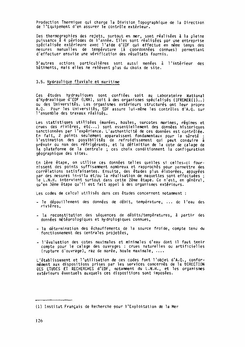
Production Thermique qui charge la Division Topographique de la Directionde l'Equipement d'en assurer le contrôle extérieur.
Des thermographies des rejets, surtout en mer, sont réalisées à la pleinepuissance a 4 périodes de l 'année. Elles sont réalisées par une entreprisespécial isée extérieure avec l 'aide d'EDF qui effectue en même temps desmesures manuelles de température (à coordonnées connues) permettantd'effectuer ensuite une vérification des résultats fournis.
D'autres actions particulières sont aussi menées à l'intérieur desbâtiments, mais elles ne relèvent plus du choix de site.
3.5. Hydraulique fluviale et maritime
Ces études hydrauliques sont confiées soit au Laboratoire Nationald'Hydraulique d'EDF (LNH), soit à des organismes spécialisés (IFREMER(l).. )ou des Universités. Les organismes extérieurs structurés ont leur propreA.Q. Pour les Universi tés, EOF assure lui-même les contrôles d 'A .Q . surl 'ensemble des travaux réalisés.
Les statistiques utilisées (marées, houles, surcotes marines, régimes etcrues des rivières, etc...) sont essentiellement des données historiquessanctionnées par l 'expérience. L'authenticité de ces données est contrôlée.En fait, 2 points seulement apparaissent fondamentaux pour la sûreté :l 'estimation des possibilités de refroidissement qui peut conduire àprévoir ou non des réfrigérants, et la définition de la cote de calage dela plateforme de la centrale ; ces choix conditionnent la configurationgéographique des sites.
En 1ère étape, on utilise ces données telles quelles si celles-ci four-nissent des points suffisamment nombreux et rapprochés pour permettre descorrélations satisfaisantes. Ensuite, des études plus élaborées, appuyéespar des mesures in-situ et/ou la réalisation de maquettes sont effectuées ;le L.N.H. intervient surtout dans cette 2ème étape. Ce n'est, en général,qu'en 3ème étape qu'i l est fait appel à des organismes extérieurs.
Les codes de calcul util isés dans ces études concernent notamment :
- le dépouillement des données de débit, température, ... de l 'eau desrivières,
- la reconstitution des séquences de débits/températures, à partir desdonnées météorologiques et hydrologiques connues,
- la détermination des échauffements de la source froide, compte tenu dufonctionnement des centrales projetées,
- l 'évaluation des cotes maximales et minimales d'eau dont il faut tenircompte pour le calage des ouvrages : crues naturelles ou art i f iciel les(rupture d'ouvrage), raz de marée, houle maximale, ....
L'établissement et l'utilisation de ces codes font l 'objet d 'A.Q., confor-mément aux dispositions prises par les services concernés de la DIRECTIONDES ETUDES ET RECHERCHES d'EDF, notamment du L.N.H., et les organismesextérieurs éventuels auxquels ces dispositions sont imposées.
(1) Institut Français de Recherche pour l 'Exploitat ion de la Mer
126

Ces études font également appel à la réalisation de maquettes ou, lorsquecela est nécessaire, de modèles réduits physiques, essentiellement lors dela phase 3 de qualification et de confirmation du site pour déterminer, parexemple, la configuration à retenir pour les ouvrages de prise et rejetd'eau.
Dans cette dernière étape, des limnigraphes enregistreurs peuvent être misen place ; ces appareils sont alors vér i f iés et relevés par un personnelspécialement formé et habilité par EOF.
3.6. Agressions externes
Pour chaque site, les risques potentiels d'agression externe doivent êtreévalués. Leur prise en compte s 'ef fectue dans le cadre défini par lesRègles Fondamentales de Sûreté (R.F.S. ) du chapître 1.2. qui définissentles principes généraux de protection contre les agressions externes compa-tibles avec la Sûreté Nucléaire.
Risques liés aux chutes d'avions
Ils font l'objet de la R.F.S. 1.2.a.
de chute desd'évaluation
Les données aériennes permettent d'estimer les probabilitésavions militaires, commerciaux et c ivi ls par une méthodedéveloppée par la Direction des Etudes et Recherches d'EDF.
L'application, à chaque site, est faite par l'Unité Opérationnelle, chargéedes études de choix de site. Les résultats,, doivent conduire à une probabi-lité de chute d'avion inférieure à 10-"/an-tranche ; dans le cas devaleurs supérieures, le site concerné peut être rejeté si aucune modif ica-tion des trafics ne peut être envisagée. L'étude permet, d'autre part, dedéfinir le type d'avion et les caractéristiques des projecti les correspon-dants dont il faut tenir compte dans la conception des ouvrages. Les résul-tats des études sont soumis à l 'approbation des Organismes de Sûreté(SCSIN).
Toutes ces études font l 'objet d 'A.Q. conformément aux règles définies parchacune des unités concernées.
Risques liés à l'environnement industriel et aux voies de communication
Ils font l'objet de la RFS I.2.d.
Ces risques sont identifiés par une recherche documentaire qui porte surles installations industrielles avec leurs caractéristiques ainsi que surles voies de communication (type de transport, fréquence de passage, etc...) au voisinage des sites étudiés. Parmi les conséquences possibles(incendie, projectile, nappes de gaz toxiques ou explosives, etc...) àexaminer dans le cadre des études de choix du site, l 'explosion est généra-lement le risque le plus contraignant.
La Direction des Etudes et Recherches a effectué de nombreux travaux etétudes générales sur l 'explosion ; en particulier, de nombreux essais ontété réalisés en liaison avec le Service National des Armées, pour vérif ierles modèles de calcul. Les résultats conduisent à définir des distanceslimites d'éloignement des sources par rapport aux sites potentiels, comptetenu des caractéristiques des projets standards. Certains sites d i f f ic i lesde ce point de vue peuvent cependant être retenus, le calcul des surpres-sions réelles engendrées sur les structures est alors effectué et cel les-cisont éventuellement renforcées. Toutes ces actions, menées par les diffé-rents services spécialisés d'EDF, en liaison avec les constructeurs^ sontsoumises aux règles d'A.Q. de chaque unité ou organisme concerne. Lesétudes sont également soumises au S.C.S.I.N.
127

Risques d ' i n o n d a t i o n s
Couvert par la RFS I.2.e., ce risque a déjà été évoqué dans le cadre desétudes hydrauliques. Les évaluations sont réal isées généralement par leLaboratoire National d'Hydraulique de la Direction des Etudes et Recherchesqui applique son programme d ' A . Q . Les résultats sont soumis à l 'approbationdu SCSIN.
En résumé, les risques l iés aux agressions externes sont évalués dès la2ème étape des études de choix de site, car ils conditionnent directementleur validité ; ils sont toutefois réévalués tout au long de la vie de lacentrale, notamnent 1-ors de l 'examen par les autorités de sûreté du rapportdéfinif i f de sûreté, afin de tenir compte des aménagements ou modif icationséventuellement survenus depuis l 'ouverture du site.
3.7. Population - Météorologie
Pour le choix d 'un site, les caractérist iques météorologiques ainsi que larépartition de la population en fonction de la distance sont des paramètresimportants pour la sûreté pu isqu ' i l s conditionnent la mise au point desplans d'urgence en cas d 'accident .
En France, les données météorologiques proviennent de l 'O f f i ce National dela Météorologie qui travail le en l iaison avec l 'Organisat ion de la Météoro-logie Mondiale. Pour les vents notamment, EOF détermine les rosés des ventsà partir de ces données avec, notamment, les distributions en fréquence parsecteur. Ces éléments sont en général suff isant dans les 2 premières étapesdes études de site.
En 3ème étape, de nouvelles mesures météorologiques spécifiques peuvents 'avérer nécessaires dans le cas où les stations de mesure du réseau natio-nal ne sont pas suffisamment représentatives ; elles sont alors réaliséessur le site projeté.
La RFS Y.l.b. "Moyens de mesures météorologiques" précise les moyens àmettre en oeuvre sur chaque site pour l 'évaluat ion du transfert atmosphéri-que de rejets d 'ef f luents radioacti fs des centrales, tant en fonctionnementnormal qu'en fonctionnement accidentel.
La mise en place et l 'exploitation de ces installations sont suivies etétudiées par le Service Météorologique de la Direction des Etudes etRecherches d'EDF qui est soumis aux règles d 'A .Q . de cette Direction.
La répartition de population autour des sites est déterminée à partir desdonnées informatiques de l ' INSEE provenant du dernier recensement connu (enFrance 1982) ; chaque commune effectue régulièrement des évaluations inter-médiaires entre 2 recensements. Un code de calcul traite toutes ces donnéesen associat ion avec celles des rosés des vents, afin de déterminer larépartition de la population en fonction de la distance et par secteur,ainsi que, notamment, les probabilités correspondantes pour la populationd'être "sous le vent . En zone proche, quelques précisions sont apportéespour tenir compte de la dispersion de l'habitat local.L'apport saisonnier de population -touristique par exemple- est directementobtenu auprès des communes concernées : l ' impossibilité d'évacuation en casd'accident peut conduire à exclure certains sites dès la 2ème étape.Ces études sont réalisées ou pilotées par le Département Sites-Environne-ment-Information (S.E. I . ) du Service Central de la Direction de l'Equi-pement d'E.D.F. Toutes ces prestations 'et celles des autres Organismesconsultés sont soumises aux règles d 'A.Q. de chaque unité.L'analyse du critère "population" est également soumise aux organismes desûreté.
128

- CONCLUSION
Le choix des sites fait intervenir plusieurs services d 'E.D.F. suivant lanature des prestations et le stade des études :
- le Département S.E. I , de la DIRECTION DE L 'EQUIPEMENT qui assure notam-ment le pilotage des études et des choix de sites potentiels au stadepréliminaire,—
- le Département T .E .G.G. de la DIRECTION DE L 'EQUIPEMENT en ce qui concer-ne les études et prospections géologiques, géotechniques et hydrogéolo-giques,
- la DIRECTION DES ETUDES ET RECHERCHES, en ce qui concerne toutes lesétudes à caractère scient i f ique très marqué, telles que :
. les études météorologiques.
. les études hydrologiques f luv ia les et maritimes,
. la plupart des codes de calcul ,
. la réalisation de modèles physiques représentatifs,
. la mise en oeuvre de campagnes de mesures par t icul ières, etc ...
- les REGIONS D'EQUIPEMENT de la DIRECTION DE L 'EQUIPEMENT, ou UnitésOpérat ionnel les pour le pilotage des études des étapes 2 et 3 du choixdes sites ainsi que pour les invest igat ions sur les sites,
et un certain nombre d'Organismes Nationaux ou Pr ivés spécia l isés, etd'experts extérieurs à EDF.
Toutes les actions entreprises, soit par E.D.F. , soit par des Organismesextérieurs à EDF, sont soumises aux règles d ' A . Q . telles qu'el les sontrappelées dans le présent document, et conformément aux modali tés définiespour chaque intervenant.
L'ensemble des études est également soumis à l 'approbation des Autorités deSûreté, dans la mesure où elles concernent directement ou indirectement laSûreté Nucléaire.
Enfin la confirmation du site, est véritablement obtenue à l 'aboutissementdes procédures administ rat ives visant à l 'obtent ion de toutes les autor isa-tions nécessaires pour démarrer la construction de la centrale.
129
LIST OF PARTICIPANTS
Consultants Meeting (C)Vienna
4-8 June 1984
Advisory Group Meetings (A)Vienna
4-8 February and 2-6 December 1985
Gürpinar, A. (C, A) Specialized Eng. ConsultingServices
Ave. Siegers 397B-1200 Brussels, Belgium
Scrim&er, D.J. (A) Atomic Energy Control BoardP.O.Box 1046Ottawa KIP 5S9, Canada
Fonne, C. (C, A) Electricité de FranceDirection de l'Equipement22 - 30 Avenue WagramF-75382 Paris, Cedex 08France
Maniori, D. (A) Comitato Nazionale per1'Energia Nucleare
Via Vitaliano Brancati, 481-00144 Roma, Italy
lelasi, R. (A) Comitato Nazionale per1'Energia Nucleare
Via Vitaliano Brancati, 481-00144 Roma, Italy
131

Heim, G.E. (C, A) Environmental ResourcesManagement, Inc.
999 West Chester PikeP.O.Box 357, West ChesterPennsylvania 19382, USA
Morrison, W.M. (A) Office of Nuclear RegulatoryResearch
U.S. Nuclear RegulatoryCommission
Washington, D.C. 20555,U.S.A.
Giuliani, P. (C, A) Division of Nuclear SafetyInternational Atomic EnergyAgency
P.O.Box 100, A 1400 ViennaAustria
Karbassioun, A. (C, A) Division of Nuclear SafetyInternational Atomic EnergyAgency
P.O.Box 100, A-1400 ViennaAu s t r i a
Raisic, N. (C, A)(Scientific Secretary)
(IAEA)
Division of Nuclear PowerInternational Atomic EnergyAgency
P.O.Box 100, A 1400 ViennaAustria
132