manual, optimized for download- model pm-1440gt lathe ...€¦ · my lathe doesn’t run at all (2)...
TRANSCRIPT

1 Copyright © 2017 Quality Machine Tools, LLCPM-1440GT 11-10-17 v4
Model PM-1440GT Lathe
High precision gap-bed machine, with coolant systemShort spindle length, large bore: 15-1/2 long x 2 inch bore
D1-5 camlock spindle mount40 in. between centers, 14 in. swing over bed, 20-3/4 in. over gap
12 spindle speeds from 50 to 2000 rpmMulti-speed gearbox for full-range screw cutting, TPI & mm pitch
Bidirectional power feed for saddle & cross-slideWeight, including stand & coolant system 1750 lb
This is a low-resolution pdf of the manual, optimized for download-ing and screen viewing. A high quality, print-ready pdf is available to purchasers of the PM-1440GT Lathe.
The PM-1440GT lathe is manufactured in Taiwan
PM-1440GT Shown with optional work light, chuck and micrometer saddle stop

2 Copyright © 2017 Quality Machine Tools, LLCPM-1440GT 11-10-17 v4
PM-1440GT
FAQ
POWER light off?
AC power connected?
Circuit breaker in the electrical box tripped?
E-STOP button in? Rotate it, should pop out.
My lathe doesn’t run at all (1)
This manual contains essential safety advice on the proper setup, operation, maintenance, and service of the PM-1440GT lathe. Failure to read, understand and follow the manual may result in property damage or serious personal injury.
There are many alternative ways to install and use a lathe. As the owner of the lathe you are solely responsible for its proper installation and safe use. Consider the material contained in this manual to be advisory only. Quality Machine Tools, LLC cannot be held liable for injury or property damage during installation or use, or from negligence, improper training, machine modifications or misuse.
This manual describes PM-1440GT machines as shipped from November 2016. There may be detail differ-ences between your specific machine and the information given here (with little or no impact on functionality). If you have questions about any aspect of the manual or your machine, please email us at [email protected]. Your feedback is welcomed!
FOOTBRAKE working, not stuck down? If working properly, the footbrake should close the microswitch (inside the LH stand cabinet), opening it when released.
The motor didn’t run when power was connected
My lathe doesn’t run at all (2)
By design it should NOT run if the Motor Control lever is UP or DOWN when power is connected.
Electrical schematic, Section 5: Move the Motor Control switch to neutral, mid travel, to energise the power-switch-ing contactor KA, thus restoring normal conditions.
Copyright © July 2017 Quality Machine Tools, LLCNo portion of this manual may be reproduced or distributed in any form without the written approval of Quality Machine Tools, LLC.
The 3 gearboxes in this machine (Headstock, Saddle Feed and Apron) may have been shipped empty. They must be filled before use, see Section 4.

3 Copyright © 2017 Quality Machine Tools, LLCPM-1440GT 11-10-17 v4 CC18.indd
Section 1 INSTALLATION
THESE ARE THE MAIN POINTS TO WATCH OUT FOR!But read the following pages for more information
• Handling the lathe is at least a two-man job.• Lifting gear – sling, hoist or forklift – must be rated for at least 1-1/2 tons.• Working location of the lathe must allow space for removal of the belt cover at left; also,
access to the coolant system (back of right hand cabinet) and the electrical box at the back of the headstock.
• Power requirement is 220V, 60Hz, 1φ (3φ optional).• Extension cord not recommended; if no alternative, use 12 AWG not longer than 20 ft.• Before connecting power be sure that:
1. The machine is on a firm footing.2. Chuck camlocks tight, no wrench left in chuck.3. Saddle and cross-slide approx. mid-travel, power feed disengaged (Figure 1-8).4. The headstock gear selectors are set for the lowest spindle speed.
SETTING UP THE LATHEThe PM-1440GT is shipped fully assembled in a single pack-ing case. The machine can be lifted in one piece by an over-head hoist or forklift with slings and/or chains, all items rated for a total weight of at least 1-1/2 tons. A suggested setup for lifting is shown in Figure 1-1.
When selecting a location for the lathe, allow sufficient room at the right to allow removal/servicing of the leadscrew, feed shaft and motor control shaft.
Be sure to keep all lifting gear clear of any part of the lathe, especially the 3 shafts at the front. Use at least 2-by spreaders.
Figure 1-3 Coolant tank
Figure 1-1 Lifting with slings
Spreader under the bed keeps slings/chains clear of feed shafts, etc.
Before lifting, remove the chuck, if installed, then move the tailstock and saddle as far to the right as possible to balance the machine at the point(s) of suspension.
With the machine in its permanent location, lower it so that its height adjustment bolts rest on the six supplied cast iron level-ing mounts, Figure 2.
Inspect the coolant tank and pump assembly in the RH cabi-net, Figure 1-3. The tank may have become dislodged in ship-ment. Level it if necessary.
Figure 1-2 Leveling mount
Check oil levels in all gearboxes before use
4 Copyright © 2017 Quality Machine Tools, LLCPM-1440GT 11-10-17 v4
POWER CONNECTIONAs shipped. the PM-1440GT is set for 220 V single or three-phase.
Read Initial Checks, below, before connecting power
Remove the rear cover from the LH cabinet. If the lathe did not come with a pre-installed power cord, connect the right hand terminals, Figure 1-6, to the power source using 12 AWG (minimum) 3-wire cord through a strain relief bushing sized for the electrical box ports. For a single phase installation, connect the power lines to terminals R and S. For three-phase connec-tion, see Section 5.
INITIAL CHECKS
Read Section 3 if unsure about any item in the following
BEFORE connecting power, do the following:
1. Visually check the entire machine for possible distur-bance in shipping, including the motor, Vee belts and external gears under the belt cover left of the headstock. Replace the belt cover.
2. Check oil level (sight glasses) in the headstock, the saddle feed gearbox, and the apron. See Section 4.
3. If a chuck or faceplate is installed, check tightness of the six Camlocks on the spindle nose, Section 3.
4. Set the speed selector gear levers to the lowest spin-dle speed, 50 rpm. Make sure the gears are properly meshed by "jiggling while shifting" — rotate the chuck back and forth by hand while moving the levers into position. Make certain that the motor control lever is set to OFF, mid-travel, Figure 1-7.
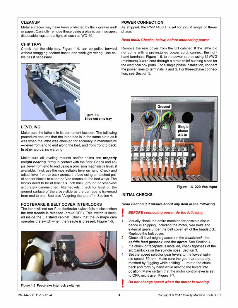
Figure 1-4Slide-out chip tray
LEVELINGMake sure the lathe is in its permanent location. The following procedure ensures that the lathe bed is in the same state as it was when the lathe was checked for accuracy in manufacture — level from end to end along the bed, and from front to back. In other words, no warping.
Make sure all leveling mounts and/or shims are properly weight bearing, firmly in contact with the floor. Check and ad-just level from end to end using a precision machinist’s level, if available. If not, use the most reliable level on hand. Check and adjust level front-to-back across the bed using a matched pair of spacer blocks to clear the Vee tenons on the bed ways. The blocks need to be at least 1/4 inch thick, ground or otherwise accurately dimensioned. Alternatively, check for level on the ground surface of the cross-slide as the carriage is traversed from end to end. See also "Aligning the Lathe" in Section 4.
FOOTBRAKE & BELT COVER INTERLOCKSThe lathe will not run if the footbrake switch fails to close when the foot treadle is released (brake OFF). This switch is locat-ed inside the LH stand cabinet. Check that the D-shape cam operates the switch when the treadle is pressed, Figure 1-5.
Do not change speed when the motor is running.
CLEANUPMetal surfaces may have been protected by thick grease and/or paper. Carefully remove these using a plastic paint scraper, disposable rags and a light-oil such as WD-40.
CHIP TRAYCheck that the chip tray, Figure 1-4, can be pulled forward without snagging coolant hoses and worklight wiring. Use ca-ble ties if necessary.
Figure 1-5 Footbrake interlock switches
Figure 1-6 220 Vac input

5 Copyright © 2017 Quality Machine Tools, LLCPM-1440GT 11-10-17 v4 CC18.indd
Figure 1-7 Motor control leverMid-travel OFF, DOWN Forward, UP Reverse
Figure 1-8 Front panel controlsThe Feed Direction knob is shown here in the neutral con-
dition (no feed), leadscrew and feed shaft disengaged.
5. Set the Feed Direction knob to its center (neutral) position, Figure 1-8.
6. Check that there are no clamps or locks on moving parts.7. Check that the footbrake treadle is released (UP).8. Set the saddle and cross-slide to approximate mid-travel.9. Connect and switch on 220 Vac power. The power lamp,
Figure 1-8, should light, unless a circuit breaker in the electrical box has tripped.
10. Be sure the Emergency Stop (E-Stop) button has not been pushed in (it should pop out when twisted clock-wise).
11. Shift the motor control lever DOWN. The spindle should turn Forward, counter clockwise, viewed at the chuck (nose) end. The control system can be rewired for DOWN = Reverse, see the electrical diagram, Section 5.
12. Check the emergency function by pressing the E-Stop button. The motor should stop. If this doesn’t happen, the E-stop function is defective, and needs attention.
13. Reset (twist) the E-Stop button to restore power.14. Check that the footbrake stops the motor.15. Return the motor control lever to OFF, mid-travel.16. Shift the motor control lever UP. The spindle should
Reverse, clockwise rotation, viewed at the chuck (nose) end. The control system can be rewired for UP = For-ward, see the electrical diagram, Section 5.
OPTIONAL TEST RUN PROCEDURERun the spindle for a few minutes, forward and reverse, at a selection of the available 12 speeds.
If desired, the saddle feed gearbox may also be run at this time, but first make certain that all components affected have been lubricated, then exercise the saddle and cross-slide manually before power-feeding — see Section 3 for power feed directions.
Precision Matthews recommends draining and refilling all three gearboxes (Headstock, Saddle Feed and Apron) af-ter approximately 20 hours of initial run time. Lubricants are specified in Section 4.
ALIGNING THE LATHEThe most important attribute of a properly set up lathe is its ability to “machine parallel”, to cut a cylinder of uniform diame-ter over its entire length. In other words, no taper.
Leveling of the lathe is a part of this, see earlier in this section. Equally important is the alignment of the center-to-center axis with the lathe bed, as seen from above. [Vertical alignment is nowhere near as critical, rarely causing taper unless the lathe is damaged or badly worn.] For more information see the final pages of Section 4, Servicing the Lathe.
6 Copyright © 2017 Quality Machine Tools, LLCPM-1440GT 11-10-17 v4
Section 2 FEATURES & SPECIFICATIONSMODEL PM-1440GT Lathe
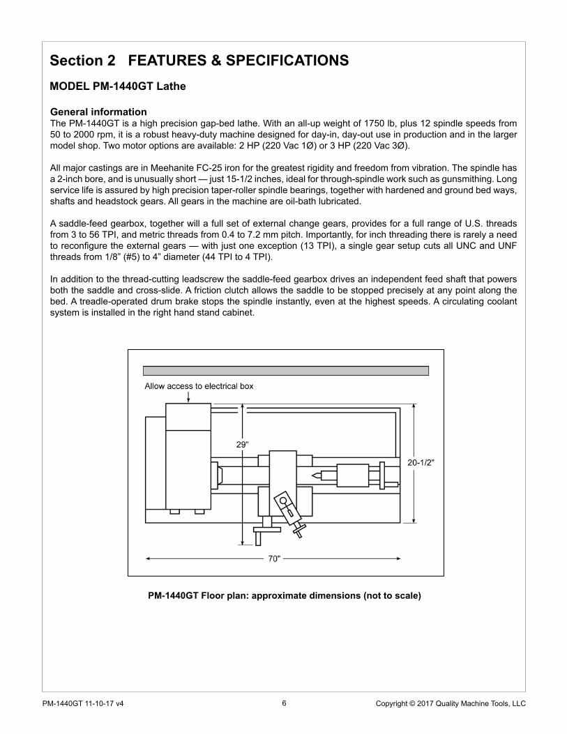
PM-1440GT Floor plan: approximate dimensions (not to scale)
General informationThe PM-1440GT is a high precision gap-bed lathe. With an all-up weight of 1750 lb, plus 12 spindle speeds from 50 to 2000 rpm, it is a robust heavy-duty machine designed for day-in, day-out use in production and in the larger model shop. Two motor options are available: 2 HP (220 Vac 1Ø) or 3 HP (220 Vac 3Ø).
All major castings are in Meehanite FC-25 iron for the greatest rigidity and freedom from vibration. The spindle has a 2-inch bore, and is unusually short — just 15-1/2 inches, ideal for through-spindle work such as gunsmithing. Long service life is assured by high precision taper-roller spindle bearings, together with hardened and ground bed ways, shafts and headstock gears. All gears in the machine are oil-bath lubricated.
A saddle-feed gearbox, together will a full set of external change gears, provides for a full range of U.S. threads from 3 to 56 TPI, and metric threads from 0.4 to 7.2 mm pitch. Importantly, for inch threading there is rarely a need to reconfigure the external gears — with just one exception (13 TPI), a single gear setup cuts all UNC and UNF threads from 1/8” (#5) to 4” diameter (44 TPI to 4 TPI).
In addition to the thread-cutting leadscrew the saddle-feed gearbox drives an independent feed shaft that powers both the saddle and cross-slide. A friction clutch allows the saddle to be stopped precisely at any point along the bed. A treadle-operated drum brake stops the spindle instantly, even at the highest speeds. A circulating coolant system is installed in the right hand stand cabinet.

7 Copyright © 2017 Quality Machine Tools, LLCPM-1440GT 11-10-17 v4 CC18.indd
Dimensions, approximate overall, incl. stand
Width 70 in. x Height 47 in. x Depth 29 in. (full range cross-slide motion)
Footprint: 68 in. wide x 16-1/2 in. deep
Bed length, excluding headstock: 51 in.
Spindle centerline to floor: 43 in.
Weight, approximate:1750 lb net
Power requirement 220 Vac, 60 Hz, 1Ø, 13A max (option: 220 Vac, 3Ø, 9A max)
Motor TEFC type, 1725 rpm, optional 2 HP 1Ø or 3 HP, 3Ø
Work envelopeHeadstock center to tailstock center 40 in. max
Swing over bed 14 in. diameter
Swing over cross-slide 8-3/4 in. diameter
Swing over gap 20-3/4 in. diameter
Gap insert length 7-3/4 in.
Spindle face to tailstock quill face 44 in. max
Saddle travel 36-1/4 in.
Cross-slide travel 6-1/2 in.
Compound (top slide) travel 3-1/2 in.
Drive systemBelt drive with 12-speed gearbox)
Low range, rpm 50, 70, 95, 140
Mid range 180, 250, 340, 510
High range, rpm 700, 980, 1350, 2000
Carriage drive, thread cutting Leadscrew 8 tpi
Inch threads Choice of 36, from 3 to 56 TPI
Metric threads Choice of 34, from 0.4 mm to 7.2 mm pitch
Saddle drive, turning operations Choice of feed rates from 0.0026 to 0.0368 in./spindle rev
Cross-slide drive, facing operations Choice of feed rates from 0.0013 to 0.0184 in./spindle rev
SpindleChuck/faceplate attachment D1-5 Camlock
Internal taper MT5-1/2
Spindle bore 2 in. diameter
Spindle length, LH end to chuck mounting face 15-1/2 in. overall
Spindle length, LH end to chuck face (typical) 19-1/2 in. approx.
TailstockInternal taper MT3
Quill travel 4 in.
Work holding (typical)
3-jaw chuck, 8 in.
4-jaw chuck, 8 in.
Faceplate
Center rest (steady rest) capacity Up to 3 in. diameter
Follower rest capacity Up to 1 in. diameter
PM-1440GT SPECIFICATIONS

8 Copyright © 2017 Quality Machine Tools, LLCPM-1440GT 11-10-17 v4
Everyday precautions
• This machine is intended for use by experienced users familiar with metal-working hazards.
• Untrained or unsupervised operators risk serious injury.
• Wear ANSI-approved full-face or eye protection at all times when using the machine (everyday eyeglasses are not reliable protection against flying par-ticles).
• Wear proper apparel and non-slip footwear – be sure to prevent hair, clothing or jewelry from becoming entangled in moving parts. Gloves – including tight-fitting disposables – can be hazardous!
• Be sure the work area is properly lit.
• Never leave chuck keys, wrenches or other loose tools on the machine. • Be sure the workpiece, toolholder(s) and machine ways are secure before
commencing operations.
• Use moderation: light cuts, low spindle speeds and slow table motion give better, safer results than “hogging”.
• Don’t try to stop a moving spindle by hand – allow it to stop on its own. • Disconnect 220 Vac power from the lathe before maintenance operations
such as oiling or adjustments.
• Maintain the machine with care – check lubrication and adjustments daily before use.
• Clean the machine routinely – remove chips by brush or vacuum, not com-pressed air (which can force debris into the ways).
No list of precautions can cover everything. You cannot be too careful!

9 Copyright © 2017 Quality Machine Tools, LLCPM-1440GT 11-10-17 v4 CC18.indd
Section 3 USING THE LATHE
DRIVE TRAINDouble-groove pulleys connect the motor to the gearbox, Fig-ure 3-3. Belt tension will not usually require attention. If adjust-ment is necessary, see Section 4.
What is not in this section ...The PM-1440GT is a conventional engine lathe that requires little explanation except for details specific to this particular model — speed selection, thread cutting, and the saddle/cross-slide power feed system. Because the user is assumed to be familiar with general purpose metal lathes, this section contains very little tutorial.
MOTOR CONTROLS Figure 3-1
Figure 3-1 Main control panel
Before doing ANYTHING, check the installation instructions and power-up procedure in Section 1
STOP the motor before changing speed
Don't use JOG unless the gears are fully meshed
Figure 3-3 Vee belts & external change gears
Figure 3-2 Motor control leverMid-travel OFF, Down FORWARD, Up REVERSE
Before connecting power to the lathe, be sure the Motor Con-trol Lever on the apron is set to OFF, Figure 3-2. Connect the lathe to a 220 Vac outlet — the POWER lamp should light — then operate the Motor Control Lever to run the spindle in the desired direction.
Check that the E-Stop button and Footbrake interlocks func-tion correctly.
Firm finger pressure here should deflect the Vee belt about 1/4"
SPINDLE SPEEDSThe PM-1440GT has a twelve-speed headstock gearbox with two shift levers, L-M-H & 1-2-3-4 (Speed Selection), Figure 3-1. Before changing speed, use the Motor Control, Figure 3-2, to STOP THE MOTOR, then move the shift levers to the desired setting. This may need a little patience because it is not always possible to go directly from one mesh to another. Move the spindle back and forth by hand while trying to ease the lever into its detent (meshed) position. Don’t use the JOG button in this process — this may cause gear damage.
SPINDLE SPEED (RPM)1 2 3 4
H RANGE 2000 1350 980 700M RANGE 510 340 250 180L RANGE 140 95 70 50

10 Copyright © 2017 Quality Machine Tools, LLCPM-1440GT 11-10-17 v4
CHUCKS & FACEPLATEThe spindle nose on the PM-1440GT accepts D1-5 Camlock chucks, faceplates and other work holding devices.
A D1-5 chuck or faceplate is held by six threaded studs, each with a D-shape crosscut to engage a corresponding cam in the spindle nose, Figures 3-4, 3-5. The function of the cams is to pull the chuck backplate inward to locate its internal taper firmly on the spindle nose.
Alongside each stud is a stop screw, the head of which fits closely in a groove at the threaded end of the stud. The func-tion of the stop screw is not to clamp the stud in place, but instead to prevent it from being unscrewed when the chuck is out on the bench.
Figure 3-5 Camlock stud
TO INSTALL A CHUCK
Disconnect the 220V supply from the lathe!
D1-5 chucks and faceplates are heavy, some more than 30 lb. They will cause serious damage if allowed to fall. Even if a chuck is light enough to be supported by one hand, the lathe bed should be protected by a wood scrap, as Figure 3-6. Some users add packing pieces, even custom-made cradles, to as-sist “straight line” installation and removal.
Before installing make certain that the mating surfaces of the chuck/faceplate and spindle are free of grit and chips.
The cams on the spindle are turned with a square-tip wrench similar to the chuck key (may be same tool in some cases).
Recommended procedure:
1. Select the highest spindle speed (2000 rpm) to allow easier hand rotation of the spindle. (Alternatively, try moving the speed selection levers between detents to find a “between teeth” condition to disengage the gear train.)
SADDLE FEED DIRECTIONThe control knob with pointer below the speed selectors, Figure 3-1, determines whether the saddle feed is right to left — the usual direction for turning and thread cutting — or reversed. The selected direction applies to both the leadscrew and the saddle/cross-slide power feed. Power feed is OFF when the knob is at 12 o'clock position, as in the photo.
Before changing feed direction, STOP THE MOTOR. Hand-turn (jiggle) the spindle while feeling for the mesh, as above. To disengage the power feed, set the Saddle Feed lever to its mid-position.
More information on the power feed system is provided later in this Section, see Saddle Feed Gearbox.
Figure 3-4 D1-5 faceplate
All stop screws must be present & fully tightened! Camlock action can jam any stud lacking a stop screw — a serious problem.
JOG FEATURE"Jog" is momentary-type push-button, active only if the Motor Control lever is in the mid-travel (OFF) position, Figure 3-2. Press the button briefly to "nudge" the spindle forward by a few degrees. Jog can be used to reposition the chuck and/or workpiece, especially useful when low spindle-speed gearing makes hand rotation difficult.
The control system can be rewired for "Reverse Jog", see the electrical diagram, Section 5.
11 Copyright © 2017 Quality Machine Tools, LLCPM-1440GT 11-10-17 v4 CC18.indd
Figure 3-7 Installing a Camlock chuck
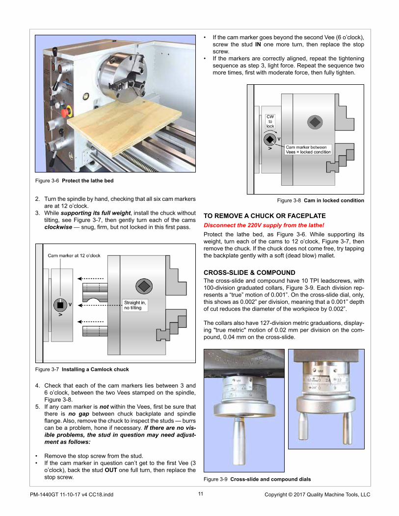
Figure 3-8 Cam in locked condition
TO REMOVE A CHUCK OR FACEPLATEDisconnect the 220V supply from the lathe!Protect the lathe bed, as Figure 3-6. While supporting its weight, turn each of the cams to 12 o’clock, Figure 3-7, then remove the chuck. If the chuck does not come free, try tapping the backplate gently with a soft (dead blow) mallet.
CROSS-SLIDE & COMPOUNDThe cross-slide and compound have 10 TPI leadscrews, with 100-division graduated collars, Figure 3-9. Each division rep-resents a “true” motion of 0.001”. On the cross-slide dial, only, this shows as 0.002” per division, meaning that a 0.001” depth of cut reduces the diameter of the workpiece by 0.002”.
The collars also have 127-division metric graduations, display-ing "true metric" motion of 0.02 mm per division on the com-pound, 0.04 mm on the cross-slide.
2. Turn the spindle by hand, checking that all six cam markers are at 12 o’clock.
3. While supporting its full weight, install the chuck without tilting, see Figure 3-7, then gently turn each of the cams clockwise — snug, firm, but not locked in this first pass.
Figure 3-6 Protect the lathe bed
4. Check that each of the cam markers lies between 3 and 6 o’clock, between the two Vees stamped on the spindle, Figure 3-8.
5. If any cam marker is not within the Vees, first be sure that there is no gap between chuck backplate and spindle flange. Also, remove the chuck to inspect the studs — burrs can be a problem, hone if necessary. If there are no vis-ible problems, the stud in question may need adjust-ment as follows:
• Remove the stop screw from the stud.• If the cam marker in question can’t get to the first Vee (3
o’clock), back the stud OUT one full turn, then replace the stop screw.
• If the cam marker goes beyond the second Vee (6 o’clock), screw the stud IN one more turn, then replace the stop screw.
• If the markers are correctly aligned, repeat the tightening sequence as step 3, light force. Repeat the sequence two more times, first with moderate force, then fully tighten.
Figure 3-9 Cross-slide and compound dials

12 Copyright © 2017 Quality Machine Tools, LLCPM-1440GT 11-10-17 v4
TAILSTOCKThe tailstock leadscrew has a 10 TPI thread, with 4 inch travel. Inch and metric graduated collars on the tailstock handwheel read 0.001” and 0.02 mm per division. A transverse slot at the narrow end of the internal taper (MT3) provides clearance for drills and other devices with tang ends. To remove tooling from the tailstock taper turn the handwheel counter-clockwise (han-dle end view) until resistance is felt, then turn the handle a little more to eject the tool. Conversely, to install a taper tool make certain that the quill is out far enough to allow firm seating.
For taper turning the tailstock may be offset by adjusting set screws on either side, Figure 3-10. To move the tailstock to the front, for instance, the screw on the lever side would be unscrewed, then the opposing set screw would be screwed in to move the upper assembly. Clamp screws hold the tailstock firmly against a transverse rib in the base casting. Loosen them if necessary to allow offsetting.
A visual indication of the offset is provided by a scale on the back surface, but this is not a reliable measure for precise work. In practice, the only way to determine the offset precisely is to "cut and try' on the workpiece, or scrap stock, homing in on the correct degree of offset in small increments.
The same issues arise when re-establishing "true zero" of the tailstock, in other words returning it to the normal axis for rou-tine operations. One way to avoid cut-and-try is to prepare in advance a bar of (say) 1" diameter quality ground stock, with precise center drillings at both ends (do this by indicating for zero TIR in a 4-jaw chuck, not in a 3-jaw unless known to be predictably accurate). The prepared bar can then be installed between centers and indicated along its length.
Figure 3-10 Tailstock
SADDLE FEED GEARBOX
Stop the motor before changing feed direction or rate
The saddle feed can be to the left, right, or disengaged, as selected by the Saddle Feed knob on the main control panel, Figure 3-1.
Figure 3-11 Saddle feed gearbox controls
ENGAGING THE POWER FEEDTo activate the feed shaft set the upper lever on the gearbox, Figure 3-11, to LETTER 'I' (selections P-Q-R-T are used only for thread cutting).
The power feed lever on the apron, Figure 3-12, is active only when the feed shaft is rotating (the split-nut lever engages the leadscrew, and is typically used only for thread cutting). When engaging power feed, move the lever gently, feeling for the gears to mesh as you go. If the gears don’t engage at the first try, use the appropriate handwheel to jog the saddle or cross-slide, whichever one you wish to move under power.
The split-nut lever — used for thread cutting — cannot be engaged unless the power feed lever is NEUTRAL, neither up or down.
The rate of power feed relative to spindle speed is set by the lower lever on the gearbox, W-X-Y-Z, together with the "speed doubler" knobs A-B and C-D. Feed rates are listed on the fol-lowing page.

13 Copyright © 2017 Quality Machine Tools, LLCPM-1440GT 11-10-17 v4 CC18.indd
Figure 3-12 Feed control levers on the apronThe split nut lever is used only for thread cutting. In the main photo the power feed lever is in its neutral — disengaged — state. To power the saddle (Longi), pull the lever OUT and UP, inset. To power the cross-slide, push the lever IN and DOWN. Test for engagement/dis-engage-ment by gently jiggling the saddle and cross-slide handwheels.
Gearshifters I - W I - X I - Y I - Z
Saddle Cross-slide
Saddle Cross-slide
Saddle Cross-slide
Saddle Cross-slide
A - D 0.021 0.0105 0.0295 0.0148 0.0368 0.0184 0.0226 0.0113
B - D 0.0105 0.0053 0.0148 0.0074 0.0184 0.0092 0.0113 0.0057
A - C 0.0053 0.0027 0.0072 0.0036 0.0092 0.0046 0.0056 0.0028
B - C 0.0026 0.0013 0.0036 0.0018 0.0046 0.0023 0.0028 0.0014
Figure 3-14 lists inches of travel per revolu-tion of the spindle, rounded to the nearest 0.001". Saddle motion is 2 times cross-slide motion. In practice most users stay with only the one gear shift setting, such as I-X, con-trolling the feed rate by the "doubler knobs", A-B and C-D. For an overall faster feed rate, use I-Y.
SADDLE & CROSS-SLIDE FEED RATESUse the same change gear setup as for TPI thread cutting (30T upper/60T lower, following page
Figure 3-14 Power feed rates (inches per spindle rev)
FEEDSHAFT CLUTCHThe clutch shown in Figure 3-15 disengages the power feed if the saddle or cross-slide hits an obstruction when power feed-ing, thus minimizing the potential for damage. This could be the result of either an accidental event, or deliberately stopping the saddle at a precise location set by the stop, Figure 3-13.
The clutch comprises a pair of spring loaded steel balls bear-ing on a detent disc driven by the saddle feed gearbox. Spring pressure is adjusted by two set screws on either side of the feed shaft, arrowed in Figure 3-15. Setting the spring pres-sure is a process of aiming for the best compromise between too high — damaging feed pressure — and too low, stopping prematurely.
Setting the clutch to work reliably with the micrometer carriage stop is a good example of such a compromise: start with low spring force, then work up in small increments until the car-riage stops in the same location (say ± 0.002”, assuming a constant depth of cut and feed rate).
SADDLE STOPThe stop assembly, Figure 3-13, has a micrometer-style collar graduated in 0.001 in. divisions. It can be clamped at any point along the lathe bed (two M6 socket head screws on the under-side secure the clamp plate to the block). Make certain that the stop rod seats firmly on the saddle casting.
Figure 3-15 Feedshaft clutchFigure 3-13 Saddle stop

14 Copyright © 2017 Quality Machine Tools, LLCPM-1440GT 11-10-17 v4
THREAD CUTTINGExternal change gearsThe large gears in Figures 3-18 are transposing gears, 120T and 127T. They allow a standard-thread leadscrew, in this case 4 TPI, to cut metric threads. The transposing gears are keyed together.
KEY FACTS TO REMEMBER ...TPI threadsWhen configured for inch thread cutting (30T upper, 60T low-er), with just one exception the lathe cuts all UNC and UNF threads from 1/8” (#5) to 4” diameter, 44 TPI to 4 TPI, without the need to change gears. The exception is 13 TPI, which re-quires 65T as the lower gear.
For inch thread cutting, the 127T larger gear is simply an idler, transferring the drive from the upper gear to the lower gear. In this configuration, the spacer bushing is outside the lower gear, as Figure 3-18.
Figure 3-16 Configuration for TPI thread cuttingFor all TPI threads (U.S.A.) the 127T gear is an idler between upper and lower gears.
Gear swappingAny change to the drive train typically calls for one or both of the upper and lower gears to be exchanged for a larger or smaller gear. This will require the transposing gear pair to be repositioned. The procedure for this is:
Figure 3-18 External change gears
Gear shifters
P-X P-X Q-X T-Z R-X R-X Q-Z P-X R-W
Lowergear 60 65 60 60 57 60 60 69 60
A-D 3 3-1/4 4 4-1/2 4-3/4 5 5-1/2 5-3/4 7
B-D 6 6-1/2 8 9 9-1/2 10 11 11-1/2 14
A-C 12 13 16 18 19 20 22 23 28
B-C 24 26 32 36 38 40 44 46 56
Figure 3-17 Threads per Inch (TPI)
1. Remove the M6 socket head screws from the upper and lower gear shafts.
2. Remove the gears, washers, keys and bushing (lower gear only).
3. While holding the gear support casting (quadrant) with one hand, use a 19 mm wrench to loosen its anchor nut. Allow the casting to swing downward.
4. Loosen the 19 mm hex nut securing the transposing gears to the support casting.
5. Install the lower gear (for TPI threads the lower gear spacer is outside, for metric threads, inside).
6. Bring the transposing gears into mesh with the lower gear, trapping a scrap of bond paper (letter stock) be-tween the two to hold them at the correct separation.
7. Tighten the transposing gears in position, then re-move the paper. Check for working clearance be-tween the gears.
8. Install the upper gear.9. Swing the gear support casting upward to mesh the
127T gear with the upper gear, again using a paper scrap for separation.
10. Tighten the gear support casting.11. Lubricate the gears.
Metric threadsWith the change gears supplied the lathe cuts all COARSE metric threads from M3 to M36 (pitches 0.5 to 4.0 mm) and all FINE metric threads from M4 to M100 (pitches 0.5 to 6.0 mm).
For metric thread cutting, the lower gear is driven by the 120T transposing gear. In this configuration, not shown, the spacer bushing is inside the lower gear.

15 Copyright © 2017 Quality Machine Tools, LLCPM-1440GT 11-10-17 v4 CC18.indd
Figure 3-19 Configuration for metric thread cuttingFor all metric thread pitches lower gear is driven by the smaller (120T) transposing gear.
Gear shifters
R-W Q-W R-W Q-W R-W Q-X Q-W Q-X
Uppergear 28 28 42 35 49 30 49 36
A-D 3.2 4.0 4.8 5.0 5.6 6.0 7.0 7.2
B-D 1.6 2.0 2.4 2.5 2.8 3.0 3.5 3.6
A-C 0.8 1.0 1.2 1.25 1.4 1.5 1.75 1.8
B-C 0.4 0.5 9.6 0.7 0.75 0.9
Figure 3-20 Metric thread pitches (mm)
COMPOUND SETUP FOR THREAD CUTTINGThread cutting on the lathe is unlike most other turning oper-ations, for two reasons: 1. The cutting tool must be precisely ground with an included angle of 60 degrees for most Amer-ican and metric threads, and; 2. It is preferable to feed the tool into the workpiece at an angle so it cuts mostly on the left flank of the thread, Figure 3-21. The correct angle relative to the cross-slide (zero degrees) is debatable — should it be 29, 29-1/2 or 30 degrees? Many machinists prefer 29 degrees be-cause it holds the cutting tool marginally clear of the right flank of the thread, close enough for cleanup of the flank while at the same time avoiding appreciable rubbing.
Figure 3-21 Setting up the compound for 30o infeed
CUTTING PROCEDURE FOR TPI THREADSThis procedure assumes that a single point thread cutting tool will be used, and that the threading dial assembly, Figure 3-22, has been pivoted forward to engage its worm wheel with the leadscrew.
The threading dial cannot used for metric threads! The split-nut on the apron must be left engaged throughout the entire process.
For metric and UNC/UNF threads the tool is ground to 60o (in-cluded angle). It is installed so that its flanks are exactly 30o either side of the cross axis, ideally with the compound off-set as Figure 3-21. Single-point threads are cut in 10 or more successive passes, each shaving a little more material off the workpiece.
To make the first thread-cutting pass the leadscrew is run at the selected setting (tables on this, and preceding pages), and the carriage is moved by hand to set the cutting tool at the starting point of the thread. With the tool just grazing the work-piece, the split-nut lever is lowered to engage the leadscrew. This can be done at any point, provided the split-nut remains engaged throughout the entire multi-pass thread cutting process.
When the first pass is completed, the tool is backed out clear the workpiece (using the cross-slide), and the spindle is re-versed to bring the saddle back to the starting point. The cross-slide is returned to its former setting, then the tool is advanced a few thousandths by the compound for the next pass. Each successive pass is done in the same way, each with a slightly increased infeed setting of the compound.
Many users working on U.S. threads save time by disengag-ing the split-nut at the end of each cutting pass, reversing the saddle by hand, then re-engaging, usually by reference to the threading dial.
If the TPI number is divisible by 2 re-engagement can be done at any line on the threading dial.
For all other TPI numbers every engagement, including the first, must at the point where a specific line on the threading

16 Copyright © 2017 Quality Machine Tools, LLCPM-1440GT 11-10-17 v4
USING THE THREADING DIALReferring to Figure 3-23, the general rules are:
1. Divide the TPI value by 2: If this gives an EVEN whole number, example 12/2 = 6, re-engage at any line on the dial, also mid-way between the lines. (This equates to the 16 choices on the dial plate, Figure 3-24.)
1. If the ÷ 2 result is an ODD whole number, examples 10/2 = 5, 14/2 = 7, re-engage at any line on the dial, but NOT mid-way between the lines.
2. If the TPI value is a whole number not divisible by 2, ex-ample 7, re-engage on the start line, or any line at right angles to it.
3. If the TPI value is fractional, but becomes a whole number when multiplied by 2, example 4-1/2, re-engage only on the start line, or its diametrical opposite.
If in doubt, re-engage on the start line!
dial comes into alignment with the datum mark. If not, the sec-ond and subsequent passes will be out of sync. In some cas-es, Figure 3-23, there is a choice of lines for re-engagement, but in every case the process calls for careful timing. [NOTE: Disengagement and re-engagement of the split-nut is not ap-plicable to metric threads].
Typical depths of cut per pass vary from an initial 0.005” or so, to as little as 0.001”, even less. A finishing pass or two with increments of only 0.0005” — or none at all, to deal with the
Figure 3-22 Threading dial
Figure 3-23 Threading dial visualization for selected U.S. threadsMinimize wear by swinging the dial indicator assembly away from the leadscrew when not in use
spring-back effect, can make all the difference between a too-tight thread and one that runs perfectly.
Assuming that the compound is set over at between 29 and 30 degrees, the total depth of cut is approximately 0.69 times the thread pitch, P (this equates to a straight-in thread depth of 0.6 times P). There may be a need for a few thousandths more in-feed than 0.69P, almost certainly not less.
17 Copyright © 2017 Quality Machine Tools, LLCPM-1440GT 11-10-17 v4 CC18.indd
Figure 3-24 Threading dial plate
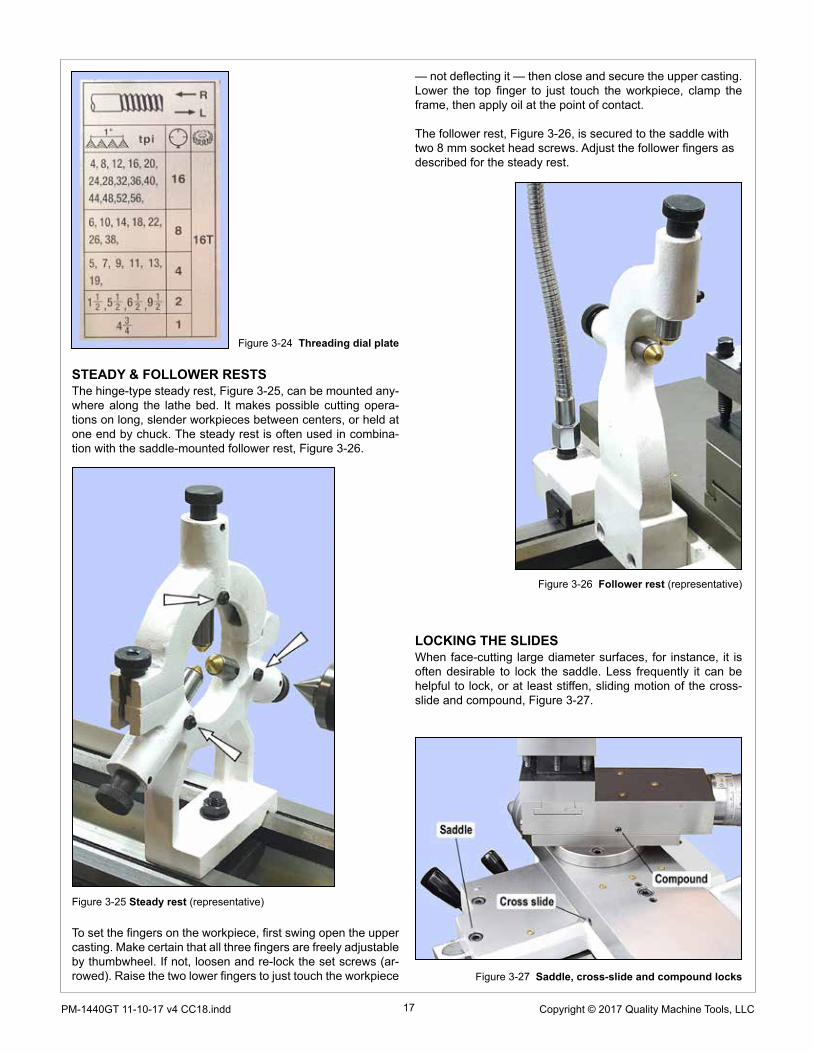
STEADY & FOLLOWER RESTSThe hinge-type steady rest, Figure 3-25, can be mounted any-where along the lathe bed. It makes possible cutting opera-tions on long, slender workpieces between centers, or held at one end by chuck. The steady rest is often used in combina-tion with the saddle-mounted follower rest, Figure 3-26.
Figure 3-25 Steady rest (representative)
To set the fingers on the workpiece, first swing open the upper casting. Make certain that all three fingers are freely adjustable by thumbwheel. If not, loosen and re-lock the set screws (ar-rowed). Raise the two lower fingers to just touch the workpiece
Figure 3-26 Follower rest (representative)
LOCKING THE SLIDESWhen face-cutting large diameter surfaces, for instance, it is often desirable to lock the saddle. Less frequently it can be helpful to lock, or at least stiffen, sliding motion of the cross-slide and compound, Figure 3-27.
— not deflecting it — then close and secure the upper casting. Lower the top finger to just touch the workpiece, clamp the frame, then apply oil at the point of contact.
The follower rest, Figure 3-26, is secured to the saddle with two 8 mm socket head screws. Adjust the follower fingers as described for the steady rest.
Figure 3-27 Saddle, cross-slide and compound locks
18 Copyright © 2017 Quality Machine Tools, LLCPM-1440GT 11-10-17 v4
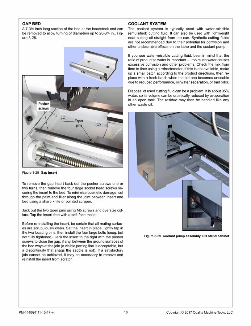
GAP BEDA 7-3/4 inch long section of the bed at the headstock end can be removed to allow turning of diameters up to 20-3/4 in., Fig-ure 3-28.
To remove the gap insert back out the pusher screws one or two turns, then remove the four large socket head screws se-curing the insert to the bed. To minimize cosmetic damage, cut through the paint and filler along the joint between insert and bed using a sharp knife or pointed scraper.
Jack out the two taper pins using M5 screws and oversize col-lars. Tap the insert free with a soft-face mallet.
Before re-installing the insert, be certain that all mating surfac-es are scrupulously clean. Set the insert in place, lightly tap in the two locating pins, then install the four large bolts (snug, but not fully tightened). Jack the insert to the right with the pusher screws to close the gap, if any, between the ground surfaces of the bed ways at the join (a visible parting line is acceptable, but a discontinuity that snags the saddle is not). If a satisfactory join cannot be achieved, it may be necessary to remove and reinstall the insert from scratch.
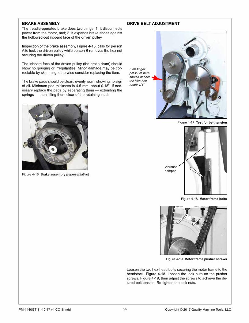
COOLANT SYSTEMThe coolant system is typically used with water-miscible (emulsified) cutting fluid. It can also be used with lightweight neat cutting oil straight from the can. Synthetic cutting fluids are not recommended due to their potential for corrosion and other undesirable effects on the lathe and the coolant pump.
If you use water-miscible cutting fluid, bear in mind that the ratio of product to water is important — too much water causes excessive corrosion and other problems. Check the mix from time to time using a refractometer. If this is not available, make up a small batch according to the product directions, then re-place with a fresh batch when the old one becomes unusable due to reduced performance, oil/water separation, or bad odor.
Disposal of used cutting fluid can be a problem. It is about 95% water, so its volume can be drastically reduced by evaporation in an open tank. The residue may then be handled like any other waste oil.
Figure 3-29 Coolant pump assembly, RH stand cabinet
Figure 3-28 Gap insert

19 Copyright © 2017 Quality Machine Tools, LLCPM-1440GT 11-10-17 v4 CC18.indd
Figure 3-30 PM-1440GT Taper turning attachment
PM-1440GT TAPER TURNING ATTACHMENTThis is a toolroom-quality fixture that can be retrofitted to any PM-1440GT lathe manufactured later than 2016. It is a self-contained, center-pivoted design that is attached by a sin-gle clamp at any point along the lathe bed. It handles tapers up to 10 inches long, with half-angle from zero to +/- 10 degrees. Taper angle is precisely settable by micrometer-style screw adjustment.
Before installing the attachment, make certain that its two sliding components — Dovetail slide and Follower carriage — move freely without side play. Adjust the gibs and lubricate if necessary.
Bear in mind that setting up any taper attachment is an iter-ative, cut and try process. In particular, if you will be using for reference a precision ground bar between centers, first be sure that the tailstock is zeroed accurately — no offset — be-
fore working on the taper attachment. The same applies to copying the taper on existing tools, such as taper-shanked reamers, many of which have center holes drilled both ends. [Center-to-center alignment is not an issue if the reference item can be held in a chuck, in which case it is only necessary to adjust for zero runout at various points along the axis.]
When copying a reference taper, be sure that the indicator probe is exactly at center height.
The taper attachment can remain in place for regular turning operations — simply remove the draw plate and reconnect the cross-slide leadscrew. (Alternatively, leave the attachment in-tact, with the taper guide bar set for zero degrees; in this case use the compound for tool control.)
Install the taper turning attachment as follows:

20 Copyright © 2017 Quality Machine Tools, LLCPM-1440GT 11-10-17 v4
Figure 3-31 Cross-slide leadscrew nut
1. Remove the socket head cap screw securing the cross-slide leadscrew nut to the cross-slide body, Figure 3-31. Push/pull the cross-slide a few times front to back to be sure the no-longer-captive nut allows free movement throughout the range called for by the taper attachment.
2. Make certain that the cross-slide gib is properly adjusted for smooth motion without side play.
3. Because the cross-slide leadscrew is inoperative, the compound is typically used to infeed the cutting tool. If the infeed needs to be precisely controlled, set the compound to 90 degrees.
4. Install the taper attachment base on the lathe carriage (4 socket head screws).
5. Install the draw plate on the cross-slide, with the two round-head socket screws (1) snug but not tight.
6. Check the underside of the draw plate where it meets the center post. It should touch the post with zero gap. Make minor adjustments to the relative height of the attachment base (4 screws), or pack with washers as necessary. (mis-alignment here can impose a vertical load on the cross-slide.)
7. Loosen the tie rod clamp screws, also the set screw se-curing cam (5). Screw the tie rod into the slide.
8. Set the clamp assembly in the desired location on the rear track of the lathe bed. Rotate the cam to raise or lower the tie rod socket (4) as necessary.
9. Tighten the tie rod and clamp screws, then re-check the center post/draw plate interface.
10. Set the draw plate as desired for the turning operation. Tighten screws (1) and (2). Tighten the cam set screw.
11. Loosen screws (3), set the desired taper angle, see be-low. Re-tighten the screws.
12. Use the carriage handwheel to run the lathe carriage back and forth a few times, checking for smooth, consis-tent functioning of both cross-slide and follower carriage. There should be no change in load from one end of the taper to the other.
13. With the workpiece installed engage carriage power feed to cut the taper.
Setting the taper angleNo matter what method you use to set the taper angle, bear in mind that all dial indicating should be done in one direction only to eliminate backlash.
1. If you are using only the angle scale on the attachment to set a taper, the taper guide bar needs first to be ze-roed relative to the lathe bed. Do this using a ground bar between centers or in a chuck, see above, with a mag-netic-based dial indicator positioned on the cross-slide so that its probe runs on the bar. Adjust the taper angle for zero deflection along the length of the bar.
2. To cut a matching taper, use the same setup to indicate the reference item, either between centers or held in the chuck. Aim for zero deflection as the probe traverses the taper. This calls for patience — expect several iterations to achieve this. Be sure the indicator probe is at center height.

21 Copyright © 2017 Quality Machine Tools, LLCPM-1440GT 11-10-17 v4 CC18.indd
Section 4 SERVICING THE LATHE
Disconnect 220V power before any maintenance operation!
Remove all machining debris and foreign objects before lubricating ANYTHING! If need be, any oil is better than no oil – but use the recommended lubricants when you can.
HEADSTOCK GEARBOX DRAIN & REFILLTake time to prepare. 4 quarts is a lot of oil to clean up!
1. Remove the belt cover, left of the headstock.2. Remove the fill plug on the top surface of the headstock,
Figure 4-1.
GENERALAside from abrasive particles and machining debris, lack of proper lubrication is the main cause of premature wear. Rotat-ing parts are easy to lubricate, sliding parts are not. Gibs are tightened for the best compromise between rigidity and slide-ability, which means practically zero gap between the ways. It is not obvious which are the bearing surfaces on the various dovetail surfaces — some of the interfaces look like bearing surfaces, but are simply narrow gaps.
Every few hours of operation: 1. Apply the recommended way-oil with a dedicated short-bristle brush such as the type used for applying flux; 2. Use a similar brush to apply oil or grease to the leadscrews; 3. Apply oil to the ball oilers, see below.
The spindle runs on sealed, pre-lubricated roller bearings re-quiring no routine attention.
Recommended lubricantsGearboxes: ISO 68, such as Mobil DTE Heavy/Medium circu-lating oil. Approximate quantities required:
Headstock 4 quarts Saddle feed gearbox 2 quarts Apron 1 quart
Ball oilers: ISO 68 way oil, such as Mobil Vactra No. 2, or equivalent.Machine ways (dovetails): ISO 68 way oil, such as Mobil Vac-tra No. 2, or equivalent.External change gears: light general purpose grease, NLGI No. 2, or equivalent.Leadscrews: ISO 68 way oil, such as Mobil Vactra No. 2, or equivalent.
BALL OILERSUse a pump-type oil can, preferably with a flexible spout tipped with a soft tube. The ID of the tip should be large enough to seat on the oiler's brass flange, more than spanning the spring-loaded steel ball. When the oil can tip is firmly pressed onto the brass surface oil pressure will displace the ball, allowing oil to flow into the bearing. Before oiling check that the ball is not stuck – press it lightly with a probe.
3. Place a drain pan (2-gallons minimum) on a stool or other support at about the height of the chip tray.
4. Fold a sheet of card stock to make a Vee-shape drain channel. This will be pressed against the headstock below the drain plug, angled downward into the drain pan; trim the upstream end of the Vee so that it seals against the headstock.
5. Run the lathe a few minutes to warm the oil if necessary.6. With the drain channel in place, remove the drain plug, Fig-
ure 4-2.7. Allow the oil to drain completely. Replace the drain plug,
then add just a few ounces of oil.8. When satisfied that the headstock is oil-tight, add oil to the
halfway mark on the sight glass, Figure 4-3 (about 4 qts).9. Replace the fill plug.
Figure 4-1 Headstock fill plug
Figure 4-2 Headstock drain plug
Figure 4-3 Headstock sight glass

22 Copyright © 2017 Quality Machine Tools, LLCPM-1440GT 11-10-17 v4
SADDLE FEED GEARBOX DRAIN & REFILLMake a card-stock Vee channel as described for draining the headstock. Remove the gearbox fill plug, Figure 4-4 (1). Re-move the gearbox front panel to expose the drain plug (2), Run the lathe for a few minutes to warm the oil if necessary. With the Vee channel in place, remove drain plug and allow the gearbox to empty completely. Replace the drain plug. To refill the gearbox use a funnel attached to a flexible plastic tube in-serted into the fill hole. Add oil to the halfway mark on the sight glass (about 2 qts).
APRON GEARBOX DRAIN & REFILLRemove the fill plug, Figure 4-6. Remove the drain plug, Fig-ure 4-7,and allow the apron to empty completely. Replace the drain plug. Add oil to the halfway mark on the sight glass (about 1 qt).
Figure 4-6 Apron gearbox fill plug
Figure 4-5 Saddle feed gearbox sight glass
Figure 4-4 Saddle feed gearbox drain & fill plugs
Figure 4-7 Apron sight glass & drain plug
BALL OILERSSee the general note on the previous page.
Figure 4-8 Saddle, cross-slide and compound oilers
Figure 4-9 Tailstock oiler

23 Copyright © 2017 Quality Machine Tools, LLCPM-1440GT 11-10-17 v4 CC18.indd
GIB ADJUSTMENTGibs on the cross-slide and compound, Figures 4-10, 4-11, are gently-tapered lengths of ground cast iron held fast by op-posing screws at each end. Adjusting them is a trial and error process that takes time and patience. Aim for the best compro-mise of rigidity and reasonably free table movement. Too tight means accelerated wear on ways and leadscrews. Too free means instability of the cutting tool, inaccuracies and chatter.
Both screw heads must be tight against the gib ends. If you loosen one, tighten the other.
The saddle gib, Figure 4-12, is not a tapered insert like those on the cross-slide and compound. It is a three-part assem-bly on the underside of the bed way at the back of the lathe. It comprises a support bar, attached to the carriage, and two separate gib strips each with two adjusting screws. Figure 4-12 Saddle gib assembly
Figure 4-10 Cross-slide & compound front gib screws
Figure 4-11 Cross-slide & compound back gib screws

24 Copyright © 2017 Quality Machine Tools, LLCPM-1440GT 11-10-17 v4
Figure 4-14 Cross-slide leadscrew nut (representative)
CROSS-SLIDE & COMPOUND BACKLASHWhen alternating between clockwise and counter clockwise rotation, the cross-slide handwheel may move freely a few de-grees but the cross-slide table stays put. There may also be similar lost motion in the compound. The acceptable amount depends on the user, but 0.005” is generally a good compro-mise. Smaller numbers are possible, but overdoing it can lead to premature wear of leadscrew and nut.
Lost motion is due to two factors: 1. End-float (in/out move-ment of the handwheel) caused by insufficiently tight coupling of the leadscrew and thrust bearings. 2. Wear in the leadscrew nut.
Factor #1 is correctable in both the cross-slide and compound.
Leadscrew handwheels on the PM-1440GT — cross-slide, compound and tailstock — are attached in a similar way, Fig-ure 4-13. The handwheel is locked to the leadscrew shaft by a key (not shown). It is held in place by a flange screw in a threaded well at the outer end of the leadscrew shaft. An in-ternal locking set screw, bottomed in the well, prevents loos-ening of the flange screw. To correct backlash due to loose coupling between leadscrew and thrust bearings, back out the set screw a turn or two, then tighten the flange screw using a pin vise or needle-nose pliers. Do not tighten to the point where the thrust bearings are over-compressed, resulting in uneven motion. Back off for smooth rotation, with no appre-ciable end-float. Re-tighten the set screw. This tends to back out the handwheel a small amount, so check end-float again.
Factor #2 is correctable in the cross-slide by compressing the leadscrew nut, Figure 4-14. Remove the compound from the cross-slide, then remove the socket head screw secur-ing the cross-slide to the leadscrew nut. Turn the cross-slide handwheel clockwise to drive the nut backward until it can be worked on at the back. Insert an M6 x 1 socket head screw, ap-proximately 15 mm long, then tighten the screw as necessary. Don't overdo this — a 45 degree turn of the screw represents a backlash take-up of about 0.005".
The compound leadscrew nut is not adjustable.
SPLIT NUT ADJUSTMENTIn thread-cutting operations, if the split nut becomes exces-sively loose — appreciable side to side movement — this may be corrected by adjusting the gib at the right side of the apron. Remove the threading dial, then tighten the two gib screws as necessary, Figure 4-15. Overtightening can make disen-gagement of the split nut difficult.
Figure 4-15 Split nut gib screws
TAILSTOCK CLAMP LEVERThe angular position of the clamp lever is adjustable. Slide the tailstock toward the headstock to expose the threaded stop screw at the right hand end of the bed. Remove the stop screw, then very carefully slide the tailstock to the right, just far enough to allow access to the hex nut below the tailstock bed plate. Tighten the nut as necessary to achieve sold locking with the lever near-vertical.Figure 4-13A Handwheel attachment schematic
Figure 4-13B Handwheel attachment
25 Copyright © 2017 Quality Machine Tools, LLCPM-1440GT 11-10-17 v4 CC18.indd
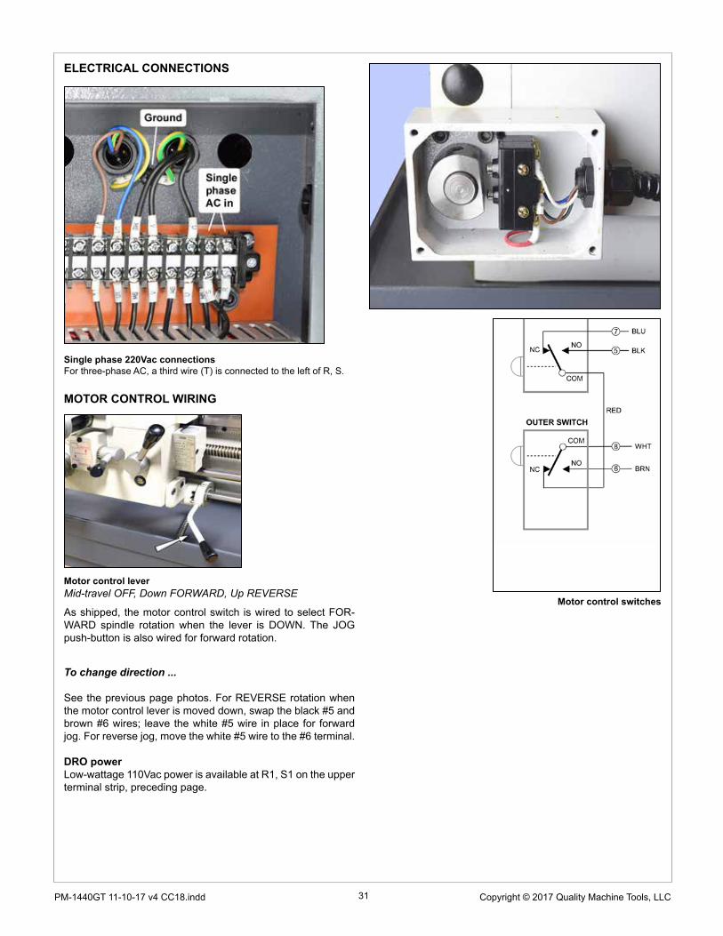
BRAKE ASSEMBLYThe treadle-operated brake does two things: 1. It disconnects power from the motor, and; 2. It expands brake shoes against the hollowed-out inboard face of the driven pulley.
Inspection of the brake assembly, Figure 4-16, calls for person A to lock the driven pulley while person B removes the hex nut securing the driven pulley.
The inboard face of the driven pulley (the brake drum) should show no gouging or irregularities. Minor damage may be cor-rectable by skimming; otherwise consider replacing the item.
The brake pads should be clean, evenly worn, showing no sign of oil. Minimum pad thickness is 4.5 mm, about 0.18". If nec-essary replace the pads by separating them — extending the springs — then lifting them clear of the retaining studs.
Figure 4-16 Brake assembly (representative)
Firm finger pressure here should deflect the Vee belt about 1/4"
DRIVE BELT ADJUSTMENT
Figure 4-17 Test for belt tension
Figure 4-18 Motor frame bolts
Figure 4-19 Motor frame pusher screws
Vibration damper
Loosen the two hex-head bolts securing the motor frame to the headstock, Figure 4-18. Loosen the lock nuts on the pusher screws, Figure 4-19, then adjust the screws to achieve the de-sired belt tension. Re-tighten the lock nuts.

26 Copyright © 2017 Quality Machine Tools, LLCPM-1440GT 11-10-17 v4
Figure B Quick alignment check
Figure A Center-to-center axis
When headstock alignment really mattersHeadstock alignment may not matter for center turning, but it's critical when the workpiece is held in a chuck or a collet — often about 90% of the workload in a typical model shop. Assuming no appreciable deflection of the workpiece (too thin, too far from the chuck), taper problems in a chuck/collet setup are due to misalignment of the spindle axis relative to the lathe bed. This is usually correctable by re-aligning the headstock.
Misalignment of the spindle by even the smallest fraction of a degree causes a very measurable taper, even over short lengths of material. For example, a misalignment as small as one hundredth of a degree will give a taper of 0.001” in 3 inches. If the headstock is (say) 10 inches long, this would be corrected by tapping one end of the headstock forward or back
ALIGNING THE LATHE
The most important attribute of a properly set up lathe is its ability to “machine parallel”, to cut a cylinder of uniform diame-ter over its entire length. In other words, no taper.
Leveling of the lathe is a part of this, see Section 1. Equally important is the alignment of the center-to-center axis with the lathe bed, as seen from above. [Vertical alignment is nowhere near as critical, rarely a cause of taper unless the lathe is dam-aged or badly worn.]
How to align lathe centersPractically all lathes come with some means of offsetting the tailstock, typically for taper turning. For routine operations, the offset must be zero, Figure A.
Precise methodThis method uses a precision ground steel rod at least 10" long. Look for 3/4 or 1 inch "drill rod" with a diameter tolerance of ± 0.001" or less.
Straightness and uniform diameter are both important (absolute diameter is not).
1. Set the rod in a collet chuck, or independent 4-jaw chuck, with the outer end about 1/2 inch clear of the chuck.
2. Use a dial indicator to check for runout. If using a 4-jaw adjust as necessary for minimum TIR (aim for 0.0005" or less).
3. Center-drill the end of the ground rod.4. Reverse the rod, re-adjust for minimum TIR, then drill the
other end.5. Set the drill rod snugly between centers, as Figure C. Lock
the tailstock.6. Set a dial indicator on the cross-slide (to eliminate vertical
error use a flat disc contact, not the usual spherical type — if a disc contact is not available, machine a cap to fit over the spherical point).
7. Starting at location (1), note which way the pointer rotates when the cross-slide is moved inward. In this setup the pointer is assumed to turn clockwise as the cross-slide moves in.
8. Pre-load the indicator by a few thousandths, then traverse the saddle from end to end. In a perfect the setup the point-er will not move at all.
If the pointer turns clockwise as you go toward the tailstock, as Figure C, the tailstock is biased to the front. This will cause the lathe to cut a tapered workpiece with the larger diameter at the headstock end. Correct this by a series of very small adjustments to the tailstock offset.
Another important question has to do with headstock/spindle alignment relative to the lathe bed. For turning between cen-ters this doesn't matter at all; the headstock can be wildly out of square, Figure D, but the lathe will still machine parallel if the centers have been aligned as previously described.
The scale usually provided on the tailstock is not reliable for precision work — think of it as only a starting point. What follows are two methods for aligning centers, one quick and easy, the other more precise.
Quick methodThis method works only if the centers are in new condition, sharp and clean.1. Carefully clean the taper sockets and the tapers them-
selves. Install the tapers.2. Move the saddle left as far as it will go, then slide the tail-
stock left to touch the saddle.3. Lock the tailstock (this is important — unlocked to locked
can mean an offset of several thousandths).4. Advance the tailstock quill to bring the centers together.5. Place a scrap of hard shim stock or an old-style dou-
ble-edge razor blade between the centers, Figure B.6. Advance the tailstock quill to trap the blade, then lock the
quill. If the centers are aligned, the blade will point squarely
front to back. If not, adjust the tailstock offset by a series of very small adjustments.
7. If the range of quill motion permits, check the blade align-ment at various extensions of the quill. There should be no appreciable variation.

27 Copyright © 2017 Quality Machine Tools, LLCPM-1440GT 11-10-17 v4 CC18.indd
Figure C Drill rod between centers
Figure D Misalignment of the headstock has no effect on center turning
by as little as 0.002”, a tiny amount even if jacking screws are provided. What this amounts to is that headstock adjustment is a highly sensitive, iterative procedure that should not be attempted casually. What follows is a general outline. Specific instructions for the PM-1440GT follow this section.
HEADSTOCK ALIGNMENT METHODSMethod 1Make a series of "cut-and-try" passes on scrap material. If the workpiece is thinner at the tailstock end, the headstock needs to be pivoted away from the tool, and vice versa.
Method 2This uses the 3/4 or 1 inch ground drill rod described in "Pre-cise method" above for center-to-center alignment.
Install the drill rod in a collet or independent 4-jaw chuck with about 5 inches protruding, Figure E. Center drilling is not need-ed.1. Adjust the chuck for minimum runout at position (1).2. Check the runout at (2). Pointer movement when traversing
is not a concern at this stage.3. If the drill rod is perfectly aligned with the spindle axis, there
should be no difference in TIR at (1) and (2).4. If there is a significant difference in TIR* from (1) to (2), try
to correct this by loosening, then re-tightening the chuck/collet, while levering the outer end of the rod (gentle tap-ping with a non-marring hammer can also be helpful). When the runout at (2) has been minimized, re-check at (1), then repeat at (2), etc.
5. When (and only when) the TIR at both locations is the same, or very close, can it be said that the rod is concentric with the spindle.
6. Compare dial indications when traversing from (1) to (2). Ideally, there will no change.
Figure E Perfect alignment: zero indicator change be-tween locations 1 and 2
* Factors that may affect runoutStraightness and roundness of the drill rod; Chuck installation (check for cleanliness and tightness); "Pointing accuracy" of the chuck (the gripping surfaces of chuck jaws may not be parallel with the axis of the chuck and spindle — especially likely if the chuck is worn).

28 Copyright © 2017 Quality Machine Tools, LLCPM-1440GT 11-10-17 v4
Figure F Morse taper test bar
PM-1440GT HEADSTOCK ALIGNMENTFigure A1 is an exaggerated top-down view of what happens if the spindle is not precisely aligned with the lathe bed. This is correctable by slightly loosening the attachment screws, Figures A2 and A3, then adjusting the screws set into a tab rail below the headstock, Figure A4.
CAUTION!Correcting headstock misalignment is a multi-step process re-quiring a number of extremely small adjustments, each one followed by an alignment test, either cut-and-try, or one of the other methods previously described.
A scarcely detectable rotation of an adjusting screw can be the difference between perfect alignment and unac-ceptable taper. In other words, think in terms of thousandths of an inch or less. Simply loosening the socket heads, Figure A4, can be enough to correct a taper problem — or add to it in the wrong direction.
Figure A3 Misaligned headstockIn this illustration the workpiece diameter increases as the cut-ting tool moves toward the chuck. Correct this by screwing in (A) a fraction of a turn to rotate the headstock counter clock-wise, moving the workpiece away from the tool. Screw in (B) if the taper is in the other direction, thinner toward the chuck.
Figure A4 Adjustment screws below the headstockThe recessed socket head screws lock the adjustment by pull-ing the tab rail toward the lathe bed. Loosen the socket heads a fraction before touching the hex heads.
Figure A3 Headstock attachment screws, LH
Figure A2 Headstock attachment screws, RH
Method 3 - Morse Taper Test BarThis is a catalog-only item available from many suppliers (de-pending on the source it may be named differently). The test bar in Figure F has a tapered shank to fit the spindle, and a parallel portion several inches long. The diameter of the paral-lel portion is unimportant. What matters more is its finish and lack of taper— check before installing. Whatever taper there may be can be allowed for in the alignment test, as Figure E. Runout should be less than 0.0005" TIR.

29 Copyright © 2017 Quality Machine Tools, LLCPM-1440GT 11-10-17 v4 CC18.indd
Section 5 PARTS
Model PM-1440GT electrical schematic

30 Copyright © 2017 Quality Machine Tools, LLCPM-1440GT 11-10-17 v4
To motor control switches (tailstock end of
lathe)
To footbrake interlock switch
To front panel controls (E-stop,
Jog, Coolant) 110 Vac out
To coolant motor
To spindle motor
Overload breaker (coolant motor)
Overload breaker (spindle motor)
5A fuse
2 x 25A fuses (not installed in some models)
24Vacrelay
220 Vac in
24 Vac out
Transformer
220 Vac in
24VacWork Light
FORWARD REVERSECOOLANTPower switching contactors
Motor direction (following page)
31 Copyright © 2017 Quality Machine Tools, LLCPM-1440GT 11-10-17 v4 CC18.indd
ELECTRICAL CONNECTIONS
Motor control leverMid-travel OFF, Down FORWARD, Up REVERSE
To change direction ...
See the previous page photos. For REVERSE rotation when the motor control lever is moved down, swap the black #5 and brown #6 wires; leave the white #5 wire in place for forward jog. For reverse jog, move the white #5 wire to the #6 terminal.
DRO powerLow-wattage 110Vac power is available at R1, S1 on the upper terminal strip, preceding page.
As shipped, the motor control switch is wired to select FOR-WARD spindle rotation when the lever is DOWN. The JOG push-button is also wired for forward rotation.
Single phase 220Vac connectionsFor three-phase AC, a third wire (T) is connected to the left of R, S.
MOTOR CONTROL WIRING
Motor control switches

32 Copyright © 2017 Quality Machine Tools, LLCPM-1440GT 11-10-17 v4
Ref Mfr# Description Qty1 2701 Left cabinet, head-
stock end1
2 2702 Right cabinet, tail-stock end
1
3 2704 Chip tray 1
4 2705 Splash guard 1
5 2709 Rear cover plate 1
6 2708 End cover plate 1
7 2707 Coolant chute 1
8 2703 Footbrake treadle 1
9 2715 Footbrake connec-tor shaft
1
10 2716 Bushing 1
11 2714 Lever 1
Cabinets, panels & coolant system
12 2713 Lever 1
13 2712 Collar 1
14 2711 Brake pull bar 1
15 2745 Expansion spring 1
16 2730 Washer 1
17 2719 Support bracket 2
18 2718 Front panel 1
19 2710 Nut 2
20 2732 Screw 1/2" x 2" 6
21 2741 Screw M6 x 12 8
22 2737 Cap screw M6 x 12 3
23 2736 Cap screw M8 x 20 1
24 2735 Cap screw M6 x 16 2
25 2734 Cap screw M8 x 20 1
26 2733 Cap screw M8 x 20 2
27 2742 Set screw M I0 x 20 2
28 2743 Set screw M I0 x 40 2
29 2731 Cap screw M8 x 10 1
30 2740 Screw M8 x 10 1
31 2746 Nut 3
32 2738 Cap screw M8 x 25 1
33 2739 Screw M8 x 30 1
34 2747 Screw M6 x 16 8
35 2748 Nut 8
36 2706 Coolant tank 1
37 2717 Coolant pump, 1/8 HP
1
38 2720 Coolant hose as-sembly
1
There may be detail differences between this representative drawing and the machine as supplied
Dimensions in millimeters

33 Copyright © 2017 Quality Machine Tools, LLCPM-1440GT 11-10-17 v4 CC18.indd
Ref Mfr # Description Qty1 2601 Bed 1
2 2602 Gap filler 1
3 2603 Rack, long 1
4 2604 Rack, short 1
5 2605 4 TPI leadscrew 1
6 2606 Feed shaft 1
7 2607 Motor control shaft 1
8 2609 Bushing 1
9 2608 Bushing 1
10 2617 End block 1
11 2611 Collar 1
12 2610 Switch box 1
13 2612 Collar 1
Lathe bed components
30 2637 Set screw M8 x 12 1
31 2638 Steel ball & spring pair 2
32 2639 Set screw M8 x 10 1
33 2640 Thrust bearing 51104 1
34 2651 Screw M8 x 60 2
35 2650 Pin 5 x 50 mm 2
36 2658 Plug 2
37 2649 Plug 1
38 2642 Set screw M8 x 10 1
39 2641 Cap screw M6 x 16 2
40 2628 Set screw M6 x 16 1
41 2629 Pin 5 x 28 mm 1
42 2643 Spring 1
43 2646 Pin 5 x 28 mm 1
44 2644 Cap screw M6 x 20 2
45 2645 Cap screw M6 x 10 1
46 2648 Set screw 8×8 1
47 2647 Nut 1
48 2630 Knob 1
49 2617A Bushing 1
50 2617B Screw M6×16 1
14 2613 Motor control bracket 1
15 2614 Collar 1
16 2615 Collar 1
17 2616 Motor control lever 1
20 2634 Cap screw 1/2-13 x 2" 6
21 2621 Washer 6
22 2622 Nut 6
23 2623 Cap screw M10 x 40 2
24 2624 Cap screw M10 x 35 2
25 2632 Cap screw M10 x 35 4
26 2633 Taper pin 2
27 2627 Nut 2
28 2636 Cap screw M6 x 20 6
29 2635 Pin 5 x 28 mm 4
There may be detail differences between this representative drawing and the machine as supplied
Dimensions in millimeters

34 Copyright © 2017 Quality Machine Tools, LLCPM-1440GT 11-10-17 v4
Ref Mfr # Description Qty
1 2101 Headstock casting 1
2 2147 Headstock cover 1
3 2129 E Shaft 1
4 2130 Gear M2: 42T+42T, 1
5 2131 Washer 1
6 2132 F Shaft 1
7 2133 Gear M2: 42T 1
8 2134 Feed dir'n control T 1
9 2135 Shift fork 1
10 2136 Shaft 2
11 2137 L-M-H shift arm 1
12 2138 Shift fork 1
13 2139 Flange 1
14 2140 Hub 2
15 2141 Lever 2
16 2142 Bushing 1
17 2143 1-2-3-4 shift arm 1
18 2144 Shift fork 1
19 2145 Gear M1.5: 22T 1
20 2146 Flange 1
21 2901 Front panel 1
22 2151 Cap screw M6 x 25 6
23 2152 Filler plug 1
24 2153 Drain plug 1
25 2154 Sight glass 1
26 2155 O-ring 1
27 2156 Retaining ring 1
28 2157 Ball bearing 6005 2
29 2158 Oil seal 30 x 47 x 8 1
30 2159 Key 5 x 18 mm 1
31 2160 Key 8 x 45 mm 1
32 2161 O-ring 1
33 2162 Retaining ring 1
34 2163 Indicator disk 3
35 2164 O-ring 2
36 2165 Cap screw M6 x 16 4
37 2166 Roll pin 5 x 40 mm 2
38 2167 Ball-spring-screw 3
39 2168 Knob 2
40 2169 Roll pin 5 x 25 mm 3
41 2170 Retaining ring 2
42 2171 Ball-spring-screw 1
43 2172 Set screw M6 x 8 1
44 2173 Screw 4
Headstock body & controls
There may be detail differences between this representa-tive drawing and the machine as supplied
All mfr numbers in the list at right are prefixed D5
Dimensions in millimeters

35 Copyright © 2017 Quality Machine Tools, LLCPM-1440GT 11-10-17 v4 CC18.indd
Headstock components
Ref Mfr # Description Qty1 2128 Nut 1
2 2127 Vee-belt pulley 1
3 2126 Pivot stud 1
4 2125 Brake actuator 1
6 2119 D shaft 1
7 2120 Gear M2: 22T 1
8 2121 Gear M2: 27T 1
9 2122 Gear M2: 38T 1
10 2123 Gear M2: 32T 1
11 2118 Plug 2
12 2112 Pinion shaft M2: 15T 1
13 2113 Gear M2: 40T 1
14 2114 Gear M2: 35T 1
15 2115 Gear M2: 24T 1
16 2116 Gear M2: 30T 1
17 2117 Plug 1
23 2106 Flange 1
31 2177 Brake shoe assembly 1
32 2178 Spring 1
33 2179 Bushing 1
34 2180 Retaining ring 1
35 2181 Cap screw M6 x 12 1
36 2182 Cap screw M6 x 25 3
37 2183 Gasket 1
38 2184 Ball bearing 6205 2
39 2185 Key 6 x 30 mm 1
40 2186 Key 7 x 75 mm 1
41 2187 Retaining ring 1
42 2188 Ball bearing 6204 2
43 2189 Retaining ring 2
44 2190 O-ring 2
45 2191 O-ring 1
46 2192 Retaining ring 3
47 2193 Retaining ring 2
48 2194 Key 8 x 40 mm 1
49 2195 Key 8 x 22 mm 1
All mfr numbers in this list are prefixed D5
There may be detail differences between this representative drawing and the machine as supplied
Dimensions in millimeters

36 Copyright © 2017 Quality Machine Tools, LLCPM-1440GT 11-10-17 v4
Ref Mfr # Description Qty18 2108 B shaft 1
19 2109 Gear M2: 22T 1
20 2111 Gear M2: 29T 1
21 2110 Gear M2: 49T 1
22 2107 Flange 1
23 2106 Nut 1
24 2105 Gear M2: 42T 1
25 2104 Gear M2: 69T 1
26 2103 Flange 1
27 2102 Main spindle (A) 1
28 2174 Camlock cam 6
29 2175 Camlock stud 6
46 2192 Retaining ring 3
50 2196 O-ring 1
51 2197 Retaining ring 1
52 2198 Key 7 x 25 mm 1
53 2199 O-ring 1
54 21100 Cap screw M6 X 25 3
55 21101 Gasket 1
56 21102 Cap screw M6 X 15 2
57 21103 Roller bearing 32013 1
58 21104 Retaining ring 1
59 21105 Roller bearing 32014 1
60 21106 Gasket 1
61 21107 Cap screw M6 X 25 1
62 21108 Key 8 x 80 mm 1
All mfr numbers in this list are prefixed D5
Headstock components
There may be detail differences between this rep-resentative drawing and the machine as supplied
Dimensions in millimeters

37 Copyright © 2017 Quality Machine Tools, LLCPM-1440GT 11-10-17 v4 CC18.indd
External change gears
Ref Mfr # Description Qty1 2801 Gear quadrant 1
2 2802 T-bolt 1
3 2803 Bushing 1
4 2804 Gear assembly M1.25: 127T/120T 1
5 2805 Quadrant anchor stud 1
6 2808 Lower change gear M1.25: 60T 1
7 2806 Spacer 1
8 2807 Upper change gear M1.25: 30T 1
9 D5-2821 End cover 1
10 2822 Stud 1
11 2824 Stud 1
12 2823 Nut 2
13 2833 Ball bearing 6202Z 2
14 2836 Retaining ring 1
15 2835 Nut 2
16 2837 Washer 1
17 2839 Washer 2
18 2840 Cap screw M6 x 16 2
19 2838 Nut 1
20 2831 Washer 1
21 2830 Key 5 x 18 1
22 2841 Key 5 x 18 1
23 2827 Data plate (US) 1
24 2817 Screw 6
Following are alternate upper gearsChange gear M1.25: 28T, 1
Change gear M1.25: 35T 1
Change gear M1.25: 36T 1
Change gear M1.25: 42T 1
Change gear M1.25: 49T 1
Following are alternate lower gearsChange gear M1.25: 57T 1
Change gear M1.25: 65T 1
Change gear M1.25: 69T 1
There may be detail differences between this representative drawing and the ma-chine as supplied
Dimensions in millimeters

38 Copyright © 2017 Quality Machine Tools, LLCPM-1440GT 11-10-17 v4
Saddle feed gearbox controls
Ref Mfr # Description Qty1 2224 Front casting 1
2 2225 P-Q-R-T inner hub 1
3 2226 W-X-Y-Z shaft 1
4 2227 W-X-Y-Z outer hub 1
5 2228 P-Q-R-T shifter plate 1
6 2229 P-Q-R-T shifter plate 1
7 2230 Shifter fork 3
8 2231 Lever 2
9 2233 A-B selector knob 1
10 2234 Shifter fork 1
11 2241 Screw 4
12 2248 Cap screw M6 x 30 6
13 2247 Ball/spring/set screw 2
14 2251 Key 5 x 10 mm 1
15 2244 O-ring 1
16 2243 Roll pin 5 x 40 mm 1
17 2242 Roll pin 5 x 30 mm 1
18 2250 Knob 2
19 2253 Ball/spring/set screw 2
20 2246 O-ring 2
21 2245 Retaining ring 2
22 2249 Indicator disk 2
23 2252 Sight glass 1
24 2254 Gasket 1
25 2232 C-D selector knob 1
26 2240 Front panel 1
There may be detail differences between this representative drawing and the ma-chine as supplied Dimensions in millimeters

39 Copyright © 2017 Quality Machine Tools, LLCPM-1440GT 11-10-17 v4 CC18.indd
Saddle feed gearbox components
Ref Mfr # Description Qty1 2201 Gearbox casting 1
2 2204 Flange 1
3 2202 A shaft 1
4 2203 Gear assy M2: 27T/18T
1
5 2236 Gear assy 14DP: 27T/30T + M2.25: 21T
1
6 2205 Flange 1
7 2206 D shaft 1
8 2218 Cover plate 1
9 2208 B shaft 1
10 2209 Gear M2: 27T 1
11 2210 Gear M2: 18T 1
12 2211 Gear M2: 36T 1
13 2217 Gear M2.25: 28T 1
14 2216 Gear M2: 30T 1
15 2215 Gear 14DP: 24T 1
16 2237 Gear 14DP: 33T 1
17 2212 Spacer 1
18 2213 E shaft 1
19 2222 Cover plate 1
20 2220 Gear assy M2: 36T/18T
1
21 2235 Gear assy 14DP: 24T/30T + M2.25: 20T
1
22 2219 C shaft 1
23 2223 Flange 1
24 2272 Pin 5 x 28 mm 2
25 2273 Cap screw M8 x 30 3
26 2256 Oil seal 22 x 35 x 7 1
27 2255 Cap screw M6 x 20 6
28 2267 Key 5 x 18 mm 1
29 2258 Key 6 x 40 mm 1
30 2259 Ball bearing 6004 3
31 2260 Retaining ring 1
32 2261 Ball bearing 6003 5
33 2262 Nut 1
34 2269 Tabbed washer 1
35 2263 Thrust bearing 51105 3
37 2275 Capscrew M6 x 20 9
38 2268 Key 6 x 55 mm 1
39 2266 Retaining ring 1
40 2264 Key 5 x 60 mm 1
41 2265 Key 5 x 12 mm 1
44 2274 Retaining ring 2
45 2276 Oil fill plug 1
46 2277 Cap screw M8 x 10 1
There may be detail differences between this rep-resentative drawing and the machine as supplied
Dimensions in millimeters

40 Copyright © 2017 Quality Machine Tools, LLCPM-1440GT 11-10-17 v4
Ref Mfr # Description Qty1 2301 Apron casting 1
11 2316 Power feed control box 1
12 2317 Control selector M1.5: 16T 1
13 2318 Power feed lever 2
14 2362 Front plate 1
23 2309 Worm 1
24 2310 Spacer ring 2
25 2325 Split nut assembly 1
26 2326 Split nut gib 1
27 2358 Sight glass, 29 mm 1
28 2357 Cap screw M8 x 10 1
29 2355 Steel ball, screw & spring set 1
30 2354 Set screw M6 x 10 3
31 2356 Plug 1
32 2352 Retaining ring 2
33 2353 Cap screw M6 x 20 2
39 2363 Cap screw M6 x 40 4
40 2360 Cap screw M8 x 25 1
41 2361 Screw 3
42 2359 Knob 1
Apron
There are differences between this representative drawing and the lathe as supplied — example: the leadscrew split-nut 25 is on the right in U.S. machines. All other shaft locations, A through F, are similarly flipped left to right.
Ref Mfr # Description Qty1 2327 Indicator body 1
2 2328-2 Threading dial (inches) 1
3 2329 Gear 16T 1
4 2366 Washer 1
5 2365 Cap screw M6 x 12 1
6 2364 Cap screw M6 x 45 1
Dimensions in millimeters
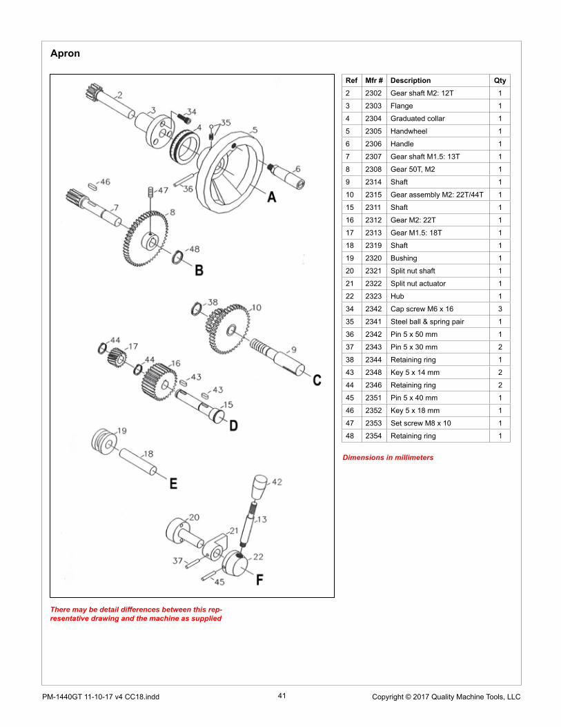
41 Copyright © 2017 Quality Machine Tools, LLCPM-1440GT 11-10-17 v4 CC18.indd
Apron
Ref Mfr # Description Qty2 2302 Gear shaft M2: 12T 1
3 2303 Flange 1
4 2304 Graduated collar 1
5 2305 Handwheel 1
6 2306 Handle 1
7 2307 Gear shaft M1.5: 13T 1
8 2308 Gear 50T, M2 1
9 2314 Shaft 1
10 2315 Gear assembly M2: 22T/44T 1
15 2311 Shaft 1
16 2312 Gear M2: 22T 1
17 2313 Gear M1.5: 18T 1
18 2319 Shaft 1
19 2320 Bushing 1
20 2321 Split nut shaft 1
21 2322 Split nut actuator 1
22 2323 Hub 1
34 2342 Cap screw M6 x 16 3
35 2341 Steel ball & spring pair 1
36 2342 Pin 5 x 50 mm 1
37 2343 Pin 5 x 30 mm 2
38 2344 Retaining ring 1
43 2348 Key 5 x 14 mm 2
44 2346 Retaining ring 2
45 2351 Pin 5 x 40 mm 1
46 2352 Key 5 x 18 mm 1
47 2353 Set screw M8 x 10 1
48 2354 Retaining ring 1
There may be detail differences between this rep-resentative drawing and the machine as supplied
Dimensions in millimeters

42 Copyright © 2017 Quality Machine Tools, LLCPM-1440GT 11-10-17 v4
Ref Mfr # Description Qty1 2401 Saddle casting 1
2 2402 Cross-slide 1
3 2403 Gib support bar 1
4 2404 Saddle gib, rear 1
5 2405 Saddle gib, front 2
6 2406 Salle lock screw 1
7 2407 Saddle lock plate 1
8 2408 Cross-slide gib 1
9 2409 Gib screw 2
10 2410 Bushing 1
11 2419 T-nut 2
12 2411 Gear M2: 13T 1
13 2412 Leadscrew 1
14 2413 Leadscrew nut 1
15 2414 Support flange 1
16 2415 Graduated collar 1
17 2417 Handwheel 1
18 2416 Locknut 1
19 2418 Handle 1
20 2439 Wiper, rear 2
21 2440 Wiper, front 2
22 2465 Index tab 1
23 2450 Oiler 5
24 2454 Cap screw M8 x 20 3
25 2453 Set screw & nut 5
26 2451 Cap screw M8 x 16 4
27 2452 Screw 8
28 2466 Cap screw 2
29 2467 Pin 2
30 2462 Cap screw M8 x 20 1
31 2461 Set screw M8 x 16 1
32 2460 Key 5 x 12 mm 1
33 2459 Pin 5 x 22 mm 1
34 2457 Thrust bearing 2902 2
35 2458 Cap screw M6 x 25 2
36 2446 Rivet 2
37 2456 Steel ball & spring 1
38 2455 Set screw 1
39 2464 Washer 1
40 2463 Cap screw M6 x 12 2
Saddle & cross-slide
There may be detail differences between this rep-resentative drawing and the machine as supplied
Dimensions in millimeters
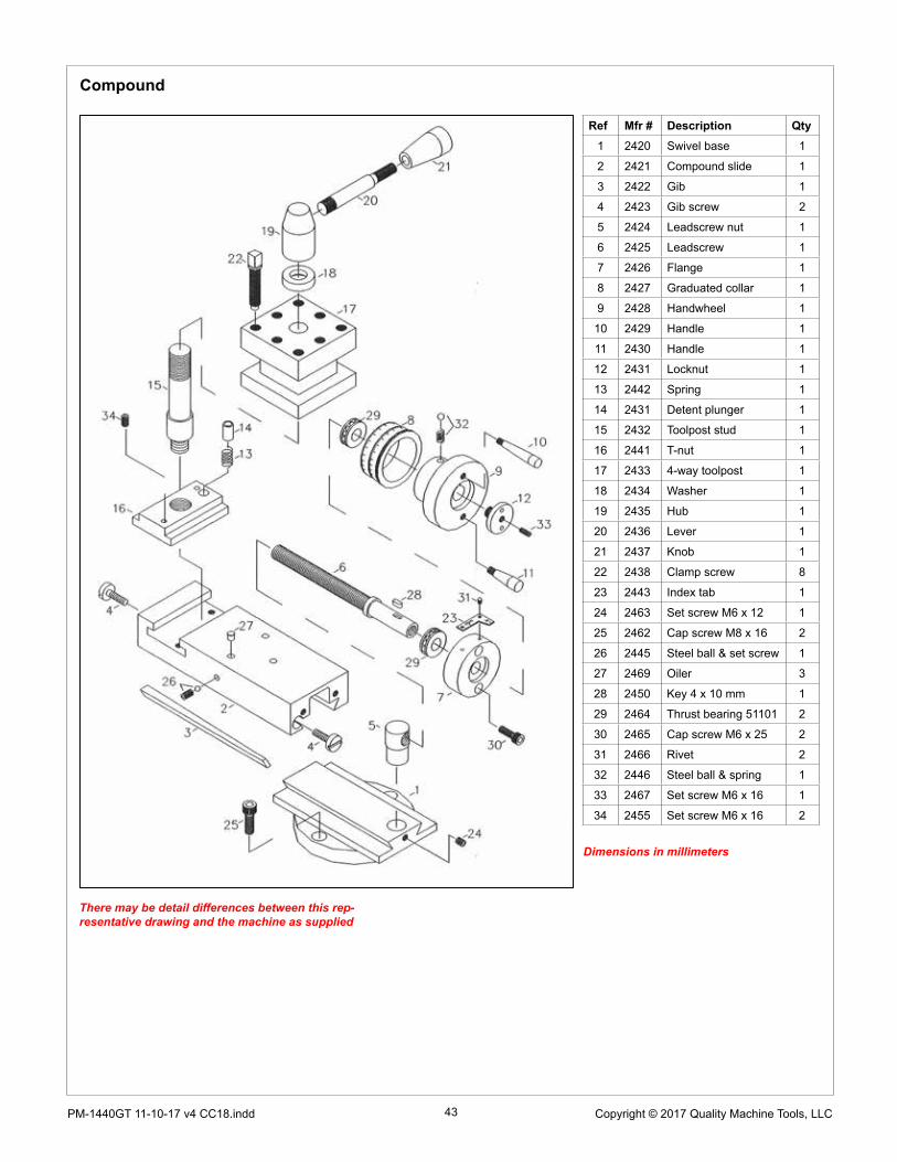
43 Copyright © 2017 Quality Machine Tools, LLCPM-1440GT 11-10-17 v4 CC18.indd
Compound
Ref Mfr # Description Qty1 2420 Swivel base 1
2 2421 Compound slide 1
3 2422 Gib 1
4 2423 Gib screw 2
5 2424 Leadscrew nut 1
6 2425 Leadscrew 1
7 2426 Flange 1
8 2427 Graduated collar 1
9 2428 Handwheel 1
10 2429 Handle 1
11 2430 Handle 1
12 2431 Locknut 1
13 2442 Spring 1
14 2431 Detent plunger 1
15 2432 Toolpost stud 1
16 2441 T-nut 1
17 2433 4-way toolpost 1
18 2434 Washer 1
19 2435 Hub 1
20 2436 Lever 1
21 2437 Knob 1
22 2438 Clamp screw 8
23 2443 Index tab 1
24 2463 Set screw M6 x 12 1
25 2462 Cap screw M8 x 16 2
26 2445 Steel ball & set screw 1
27 2469 Oiler 3
28 2450 Key 4 x 10 mm 1
29 2464 Thrust bearing 51101 2
30 2465 Cap screw M6 x 25 2
31 2466 Rivet 2
32 2446 Steel ball & spring 1
33 2467 Set screw M6 x 16 1
34 2455 Set screw M6 x 16 2
There may be detail differences between this rep-resentative drawing and the machine as supplied
Dimensions in millimeters

44 Copyright © 2017 Quality Machine Tools, LLCPM-1440GT 11-10-17 v4
Rests
Ref Mfr. # Description Qty1 2917 Steady rest casting 1
2 2918 Hinge casting 1
3 2919 Plunger 5
4 2920 Adjusting screw 5
5 2905 Collar 5
6 2921 Thumb nut 5
7 2922 Cone point 5
8 2923 Hinge clamp screw 1
9 2924 Thumb nut 1
10 2925 Hinge pivot 1
11 2930 Lock nut 5
12 2926 Set screw 5
13 2927 Set screw 5
14 2928 Roll piin 5
15 2929 Roll pin 1
16 2915 Traveler casting 1
17 2916 Screw 2
There may be detail differences between this rep-resentative drawing and the machine as supplied
Dimensions in millimeters

45 Copyright © 2017 Quality Machine Tools, LLCPM-1440GT 11-10-17 v4 CC18.indd
Tailstock
1 2501 Tailstock casting 1
2 2502 Base 1
3 2503 Quill 1
4 2504 Flange nut 1
5 2505 Feed screw 1
6 2506 Flange 1
7 2507 Graduated collar 1
8 2508 Handwheel 1
9 2509 Flange screw 1
10 2510 Handle 1
11 25 I I Quill clamp block 1
12 2512 Quill clamp shaft 1
13 2513 Quill clamp lever 1
14 2514 Tailstock clamp collar 1
15 2515 Tailstock clamp camshaft 1
16 2516 Tailstock clamp stud 1
17 2517 Clamp base 1
18 2518 Tailstock clamp lever 1
19 2519 Key 1
20 2520 Set screw M8 x 30 2
21 2521 Set screw M8 x 30 2
22 2522 Washer Ml2 1
23 2523 Nut M12 1
24 2524 Steel ball & spring 1
25 2525 Set screw M5 x 10 1
26 2526 Knob 2
27 2528 Key 5 x 12 1
28 2529 Thrust bearing 2902 1
29 2530 Cap screw M6 x 20 3
30 2531 Lock screw M6 x 16 1
31 2527 Oiler 1
32 2532 Cap screw M5 x l6 3
There may be detail differences between this rep-resentative drawing and the machine as supplied
Dimensions in millimeters