manual or option section - decode systems · ( ) 10 mhz low phase noise output(s) manual section...
TRANSCRIPT

Model 600-000
XL-AK Time and Frequency Receiver
Serial No. ___________________________September 17, 2001
Revision A
000.CFG 1 of 1 Rev. A
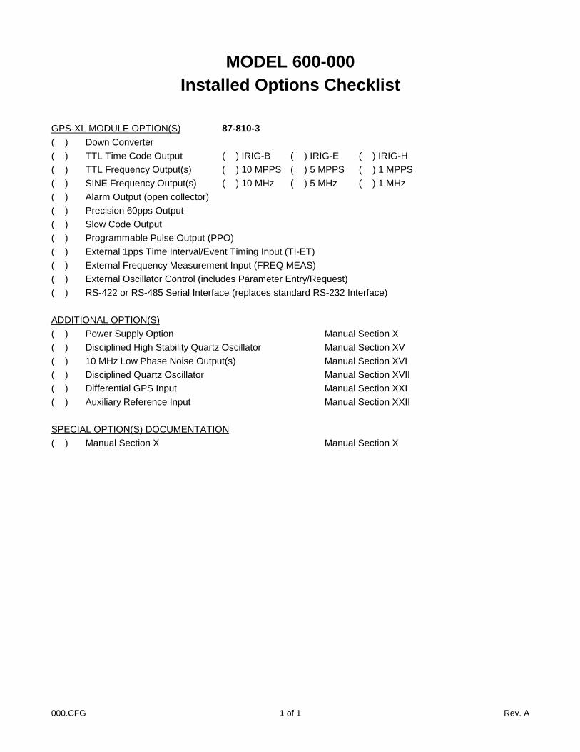
MODEL 600-000Installed Options Checklist
GPS-XL MODULE OPTION(S) 87-810-3( ) Down Converter( ) TTL Time Code Output ( ) IRIG-B ( ) IRIG-E ( ) IRIG-H( ) TTL Frequency Output(s) ( ) 10 MPPS ( ) 5 MPPS ( ) 1 MPPS( ) SINE Frequency Output(s) ( ) 10 MHz ( ) 5 MHz ( ) 1 MHz( ) Alarm Output (open collector)( ) Precision 60pps Output( ) Slow Code Output( ) Programmable Pulse Output (PPO)( ) External 1pps Time Interval/Event Timing Input (TI-ET)( ) External Frequency Measurement Input (FREQ MEAS)( ) External Oscillator Control (includes Parameter Entry/Request)( ) RS-422 or RS-485 Serial Interface (replaces standard RS-232 Interface)
ADDITIONAL OPTION(S)( ) Power Supply Option Manual Section X( ) Disciplined High Stability Quartz Oscillator Manual Section XV( ) 10 MHz Low Phase Noise Output(s) Manual Section XVI( ) Disciplined Quartz Oscillator Manual Section XVII( ) Differential GPS Input Manual Section XXI( ) Auxiliary Reference Input Manual Section XXII
SPECIAL OPTION(S) DOCUMENTATION( ) Manual Section X Manual Section X


iiXXLLAAKKMMAANN..DDOOCC ii
TABLE OF CONTENTS
SECTION TITLE
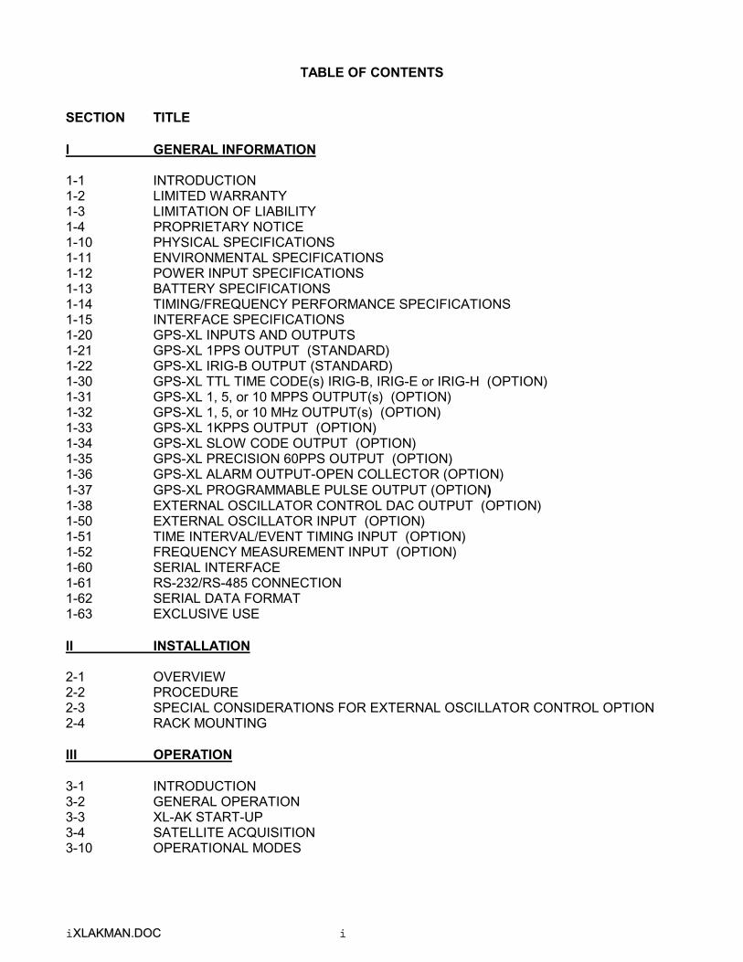
I GENERAL INFORMATION
1-1 INTRODUCTION1-2 LIMITED WARRANTY1-3 LIMITATION OF LIABILITY1-4 PROPRIETARY NOTICE1-10 PHYSICAL SPECIFICATIONS1-11 ENVIRONMENTAL SPECIFICATIONS1-12 POWER INPUT SPECIFICATIONS1-13 BATTERY SPECIFICATIONS1-14 TIMING/FREQUENCY PERFORMANCE SPECIFICATIONS1-15 INTERFACE SPECIFICATIONS1-20 GPS-XL INPUTS AND OUTPUTS1-21 GPS-XL 1PPS OUTPUT (STANDARD)1-22 GPS-XL IRIG-B OUTPUT (STANDARD)1-30 GPS-XL TTL TIME CODE(s) IRIG-B, IRIG-E or IRIG-H (OPTION)1-31 GPS-XL 1, 5, or 10 MPPS OUTPUT(s) (OPTION)1-32 GPS-XL 1, 5, or 10 MHz OUTPUT(s) (OPTION)1-33 GPS-XL 1KPPS OUTPUT (OPTION)1-34 GPS-XL SLOW CODE OUTPUT (OPTION)1-35 GPS-XL PRECISION 60PPS OUTPUT (OPTION)1-36 GPS-XL ALARM OUTPUT-OPEN COLLECTOR (OPTION)1-37 GPS-XL PROGRAMMABLE PULSE OUTPUT (OPTION)1-38 EXTERNAL OSCILLATOR CONTROL DAC OUTPUT (OPTION)1-50 EXTERNAL OSCILLATOR INPUT (OPTION)1-51 TIME INTERVAL/EVENT TIMING INPUT (OPTION)1-52 FREQUENCY MEASUREMENT INPUT (OPTION)1-60 SERIAL INTERFACE1-61 RS-232/RS-485 CONNECTION1-62 SERIAL DATA FORMAT1-63 EXCLUSIVE USE
II INSTALLATION
2-1 OVERVIEW2-2 PROCEDURE2-3 SPECIAL CONSIDERATIONS FOR EXTERNAL OSCILLATOR CONTROL OPTION2-4 RACK MOUNTING
III OPERATION
3-1 INTRODUCTION3-2 GENERAL OPERATION3-3 XL-AK START-UP3-4 SATELLITE ACQUISITION3-10 OPERATIONAL MODES

TABLE OF CONTENTS (Continued)
SECTION TITLE
III OPERATION (Continued)
3-11 AUTO MODE3-12 SURVEY MODE3-13 TIME MODE3-20 TIME QUALITY INDICATION3-21 FRONT PANEL INTERFACE3-23 ALPHANUMERIC DISPLAY3-24 TIME PUSH BUTTON3-25 STATUS PUSH BUTTON3-26 POSITION PUSH BUTTON3-27 KEYPAD OPERATION3-28 SELECTING FUNCTIONS AND ENTERING DATA3-99 KEYPAD FUNCTION LIST3-100 KEYPAD FUNCTION 00 - KEYPAD HELP FUNCTION3-101 KEYPAD FUNCTION 01 - TIME ZONE ENTRY/REQUEST3-102 KEYPAD FUNCTION 02 - 12/24 HOUR FORMAT ENTRY REQUEST3-103 KEYPAD FUNCTION 03 - TIME/DATE ENTRY/REQUEST3-104 KEYPAD FUNCTION 04 - SERIAL PORT SETUP3-105 KEYPAD FUNCTION 05 - TIME QUALITY ENABLE/SETUP3-106 KEYPAD FUNCTION 06 - KEYPAD LOCKOUT ENABLE3-107 KEYPAD FUNCTION 07 - EXTERNAL OSCILLATOR ENABLE (OPTION)3-113 KEYPAD FUNCTION 13 - WORST-CASE TIME ERROR REQUEST3-114 KEYPAD FUNCTION 14 - EXTERNAL OSCILLATOR PARAMETER ENTRY/REQUEST (OPTION)
3-116 KEYPAD FUNCTION 16 - EMULATION MODE ENABLE3-116.1 SERIAL PORT EMULATION COMMANDS3-116.2 MODE C - CONTINUOUS TIME, ONCE PER SECOND3-116.3 MODE F - FORMAT THE TIME MESSAGE3-116.4 MODE R - RESET TO DEFAULT AND MODE C3-116.5 MODE T - TIME ON REQUEST3-117 KEYPAD FUNCTION 17 - SLOW CODE SETUP (OPTION)3-118 KEYPAD FUNCTION 18 - SOFTWARE VERSION REQUEST3-128 KEYPAD FUNCTION 28 - TIME INTERVAL/EVENT TIMING INPUT (OPTION)3-129 KEYPAD FUNCTION 29 - FREQUENCY MEASUREMENT INPUT (OPTION)3-131 KEYPAD FUNCTION 31 - BACKLIGHT ENABLE (OPTION)3-150 KEYPAD FUNCTION 50 - POSITION ENTRY/REQUEST3-151 KEYPAD FUNCTION 51 - ANTENNA CABLE DELAY ENTRY/REQUEST3-152 KEYPAD FUNCTION 52 - DISTRIBUTION CABLE DELAY ENTRY/REQUEST3-153 KEYPAD FUNCTION 53 - OPERATIONAL MODE ENTRY/REQUEST3-155 KEYPAD FUNCTION 55 - ALTITUDE UNITS ENTRY/REQUEST3-156 KEYPAD FUNCTION 56 - AVERAGE POSITION ENTRY/REQUEST3-160 KEYPAD FUNCTION 60 - SATELLITES LIST REQUEST3-165 KEYPAD FUNCTION 65 - SATELLITE SELECT

TABLE OF CONTENTS (Continued)
SECTION TITLE
III OPERATION (Continued)
3-166 KEYPAD FUNCTION 66 - DAYLIGHT SAVING ENABLE3-168 KEYPAD FUNCTION 68 - YEAR ENTRY (GPS EPOCH MANAGEMENT)3-169 KEYPAD FUNCTION 69 - SELECT LOCAL/STANDARD/GPS/UTC TIME3-171 KEYPAD FUNCTION 71 - OSCILLATOR STATISTICS REQUEST3-172 KEYPAD FUNCTION 72 - FAULT STATUS REQUEST3-173 KEYPAD FUNCTION 73 - REQUEST/SET ALARM STATUS/CONTROL3-179 KEYPAD FUNCTION 79 - WARM START3-197 GENERAL SERIAL INPUT AND OUTPUT FORMAT3-198 SERIAL ERROR MESSAGES3-199 SERIAL FUNCTION LIST3-201 SERIAL FUNCTION F01 - TIME ZONE ENTRY/REQUEST3-202 SERIAL FUNCTION F02 - 12/24 HR FORMAT ENTRY/REQUEST3-203 SERIAL FUNCTION F03 - TIME/DATE ENTRY/REQUEST3-205 SERIAL FUNCTION F05 - TIME QUALITY ENABLE/SETUP3-206 SERIAL FUNCTION F06 - KEYPAD LOCKOUT ENABLE3-207 SERIAL FUNCTION F07 - EXTERNAL OSCILLATOR ENABLE (OPTION)3-208 SERIAL FUNCTION F08 - CONTINUOUS TIME ONCE PER SECOND ENABLE3-209 SERIAL FUNCTION F09 - TIME ON REQUEST ENABLE3-211 SERIAL FUNCTION F11 - TIME OUTPUT FORMAT ENTRY/REQUEST3-213 SERIAL FUNCTION F13 - WORST-CASE TIME ERROR REQUEST3-214 SERIAL FUNCTION F14 - EXTERNAL OSCILLATOR PARAMETER ENTRY/REQUEST
(OPTION)3-215 SERIAL FUNCTION F15 - EXCLUSIVE USE ENABLE3-217 SERIAL FUNCTION F17 - SLOW CODE SETUP (OPTION)3-218 SERIAL FUNCTION F18 - SOFTWARE VERSION REQUEST3-226 SERIAL FUNCTION F26 - PROGRAMMABLE PULSE OUTPUT3-228 SERIAL FUNCTION F28 - TIME INTERVAL/EVENT TIMING INPUT (OPTION)3-229 SERIAL FUNCTION F29 - FREQUENCY MEASUREMENT INPUT (OPTION)3-250 SERIAL FUNCTION F50 - POSITION ENTRY/REQUEST3-251 SERIAL FUNCTION F51 - ANTENNA CABLE DELAY ENTRY/REQUEST3-252 SERIAL FUNCTION F52 - DISTRIBUTION CABLE DELAY ENTRY/REQUEST3-253 SERIAL FUNCTION F53 - OPERATIONAL MODE ENTRY/ REQUEST3-255 SERIAL FUNCTION F55 - ALTITUDE UNITS ENTRY/ REQUEST3-256 SERIAL FUNCTION F56 - AVERAGE POSITION ENTRY/ REQUEST3-260 SERIAL FUNCTION F60 - SATELLITES LIST REQUEST3-265 SERIAL FUNCTION F65 - SATELLITE SELECTION3-266 SERIAL FUNCTION F66 - DAYLIGHT SAVING ENABLE3-268 SERIAL FUNCTION F68 - YEAR ENTRY (GPS EPOCH MANAGEMENT)3-269 SERIAL FUNCTION F69 - SELECT LOCAL/STANDARD/GPS/UTC TIME3-271 SERIAL FUNCTION F71 - OSCILLATOR STATISTICS REQUEST3-272 SERIAL FUNCTION F72 - FAULT STATUS REQUEST3-273 SERIAL FUNCTION F73 - REQUEST/SET ALARM STATUS/CONTROL3-279 SERIAL FUNCTION F79 - WARM START
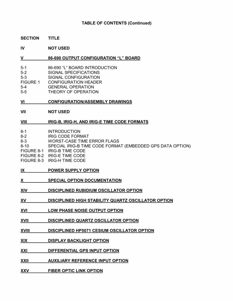
TABLE OF CONTENTS (Continued)
SECTION TITLE
IV NOT USED
V 86-690 OUTPUT CONFIGURATION “L” BOARD
5-1 86-690 “L” BOARD INTRODUCTION5-2 SIGNAL SPECIFICATIONS5-3 SIGNAL CONFIGURATIONFIGURE 1 CONFIGURATION HEADER5-4 GENERAL OPERATION5-5 THEORY OF OPERATION
VI CONFIGURATION/ASSEMBLY DRAWINGS
VII NOT USED
VIII IRIG-B, IRIG-H, AND IRIG-E TIME CODE FORMATS
8-1 INTRODUCTION8-2 IRIG CODE FORMAT8-3 WORST-CASE TIME ERROR FLAGS8-10 SPECIAL IRIG-B TIME CODE FORMAT (EMBEDDED GPS DATA OPTION)FIGURE 8-1 IRIG-B TIME CODEFIGURE 8-2 IRIG-E TIME CODEFIGURE 8-3 IRIG-H TIME CODE
IX POWER SUPPLY OPTION
X SPECIAL OPTION DOCUMENTATION
XIV DISCIPLINED RUBIDIUM OSCILLATOR OPTION
XV DISCIPLINED HIGH STABILITY QUARTZ OSCILLATOR OPTION
XVI LOW PHASE NOISE OUTPUT OPTION
XVII DISCIPLINED QUARTZ OSCILLATOR OPTION
XVIII DISCIPLINED HP5071 CESIUM OSCILLATOR OPTION
XIX DISPLAY BACKLIGHT OPTION
XXI DIFFERENTIAL GPS INPUT OPTION
XXII AUXILIARY REFERENCE INPUT OPTION
XXV FIBER OPTIC LINK OPTION

XXLLAAKKMMAANN..DDOOCC 11--11
SECTION I
GENERAL INFORMATION
1-1 INTRODUCTION
This manual provides the user of a Model XL-AK-600 or XL-AK-601 Time and Frequency Receiver allof the information necessary to properly install, operate, and utilize all of its features. NOTE:Assembly and/or schematic drawings that may be included in this manual will be identified as 600-100for the XL-AK-600 units and 600-101 for the XL-AK-601 units. Only Maintenance manuals will includeschematic drawings. Model XL-AK-600 units do not have a front panel keypad or display.
The information in this manual includes normal installation procedures as well as any maintenance andadjustment data that may be required to facilitate field repairs.
The purpose of the Model XL-AK is to provide accurate time, frequency and position as derived fromCoarse Acquisition (C/A) Link 1 (L1) signals transmitted by the NAVSTAR Global Positioning System(GPS) satellites. In addition it provides high resolution measurements of external time and frequencysignals applied as inputs to the XL-AK versus the GPS reference. The XL-AK is usable on aworld-wide basis under any weather conditions.
The XL-AK is completely automatic in satellite acquisition and time and frequency synchronization.When the unit is first installed (or if the unit is moved more than 100 km, or if the internal battery wasdischarged), acquisition time is shortened if the operator enters a position accurate to better than 100kilometers (approximately one degree in latitude and longitude).
The XL-AK receiver will operate when the satellites are 10 degrees above the horizon and their signalsare not obstructed. Whenever entered position information is less accurate than 10 meters, the XL-AKwill first have to accurately ascertain its antenna position by tracking four or more satellites andperforming a long term (24 hours) average of position fixes in order to maintain time and frequencyaccuracy and stability within specification. From that point on, the XL-AK will require only one satellite(above 10 degrees) to maintain valid time and frequency. However, operation to specified stabilityrequires four or more satellites. When no satellites are in view, the XL-AK will continue to output itssignals using either the internal or OPTIONAL external disciplined oscillator.
1-2 LIMITED WARRANTY
Each new product manufactured by TrueTime is warranted for defects in material or workmanship for aperiod of one year from date of shipment ("Limited Warranty"). Defects in material or workmanshipfound within that period will be replaced or repaired, at TrueTime's option, without charge for materialor labor, provided the customer returns the equipment, freight prepaid, to the TrueTime factory underthis limited warranty. TrueTime will return the repaired equipment, freight prepaid, to the customer'sfacility. This one year Limited Warranty does not apply to any software or to any product notmanufactured by TrueTime.
If on-site warranty repair or replacement is required, the customer will be charged the then current fieldservice rate for portal-to-portal travel time plus actual portal-to-portal travel charges. There is nocharge for on-site warranty repair labor.

XXLLAAKKMMAANN..DDOOCC 11--22
Products not manufactured by TrueTime but included as integral part of a system (e.g. peripherals,options) are warranted for 90 days, or longer as provided by the original equipment manufacturer, fromdate of shipment.
Aside from the Limited Warranty set forth above, TrueTime makes no other warranties, express orimplied, of merchantability, fitness for purpose or of any other kind or description whatsoever.
By purchasing any product manufactured by TrueTime, the buyer consents to and agrees withTrueTime that as a result of the exclusion of all warranties, expressed or implied, of merchantability,fitness for purpose, or otherwise, except for the limited one-year warranty for defects in material andworkmanship for products manufactured by TrueTime, that the Buyer has the sole responsibility toassess and bear all losses relating to: (1) the ability of the product or products purchased to passwithout objection under the contract description among merchants and buyers in the trade; (2) theconformity of the product or products to fair average quality within its contract description; (3) thefitness of the product for the ordinary purposes for which such product is used; (4) the consistency ofquality and quantity within each unit of product or products and among all units involved; (5) theadequacy of containers, packaging and labeling of the product or products; (6) the conformity of theproduct, promises or affirmations of fact (if any) made on its label or container; and (7) the conformityof the product to standards of quality observed by other merchants in the trade with respect to productsof similar description.
1-3 LIMITATION OF LIABILITY
By purchasing any product from TrueTime the Buyer consents to and agrees that the Buyer's sole andexclusive remedy for any damages or losses incurred by the Buyer as a result of TrueTime's breach ofits one-year Limited Warranty for defects in materials and workmanship or otherwise in connection withany claim respecting the product shall be limited to the repair or replacement of the product or a refundof the sales price of the product.
In no event shall the Buyer be entitled to recover consequential damages or any other damages of anykind or description whatsoever.
1-4 PROPRIETARY NOTICE
THIS DOCUMENT, WHETHER PATENTABLE OR NON-PATENTABLE SUBJECT MATTER,EMBODIES PROPRIETARY AND CONFIDENTIAL INFORMATION AND IS THE EXCLUSIVEPROPERTY OF TRUETIME, INC. IT MAY NOT BE REPRODUCED, USED OR DISCLOSED TOOTHERS FOR ANY PURPOSE EXCEPT THAT FOR WHICH IT IS LOANED, AND IT SHALL BERETURNED UPON DEMAND.
1-5 through 1-9 reserved

XXLLAAKKMMAANN..DDOOCC 11--33
1-10 PHYSICAL SPECIFICATIONS
The XL-AK is a 19” rack-mounted product with the following physical specifications:
XL-AK Receiver Size: 1.75 in. x 17.0 in. x 10.5 in.(4.45 cm. x 43.18 cm. x 26.67 cm.)Standard 19" EIA Rack System, hardware included
Antenna Size (Bullet): 3.04 in. dia. x 2.94 in.(7.72 cm. dia. x 7.47 cm.)
Antenna Size (DSK): 2.625 in. dia. X 1.5 in.(Optional) (6.67 cm. dia. X 3.81 cm.)
Antenna/DownConverter Size: 2.625 in. dia. x 8.6 in.(Optional) (6.67 cm. dia. x 21.84 cm.)
NOTE: Antenna and Antenna/DownConverter Units are mounted on a 12 in. long PVC nipple with 3/4"Male Pipe Thread (MPT) on both ends. The above specified overall lengths of the Antenna andAntenna/DownConverter Units are therefore increased by approximately 11.25 in. when the mountingnipple is included.
XL-AK Receiver Weight: 7.0 lb max. (3.175 Kg)
Antenna Weight: 0.70 lb (.318 Kg)(Including mtg. nipple)
Antenna/DownConverter Weight: 2.35 lb (1.067 Kg)(Including mtg. nipple)(Optional)
Antenna Cable, RG-59: Standard length = 50 ft.1.2 lb (.545 Kg)
Antenna/DownConverter Available lengths = 150 - 1500 ft.Cable, RG-58: 2.7 lb (1.23 Kg) per 100 ft.(Optional)
1-11 ENVIRONMENTAL SPECIFICATIONS
Operating Temperature:Antenna or Ant/DownConverter: -40° to +70° C (-40° to +158° F)XL-AK Receiver: 0° to +50° C (+32° to +122° F)
Storage Temperature:Antenna or Ant/DownConverter: -55° to +85° C (-67° to +185° F)XL-AK Receiver: -40° to +85° C (-40° to +185° F)
XXLLAAKKMMAANN..DDOOCC 11--44
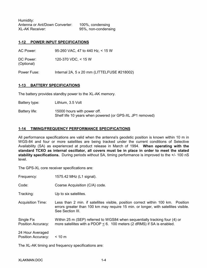
Humidity:Antenna or Ant/Down Converter: 100%, condensingXL-AK Receiver: 95%, non-condensing
1-12 POWER INPUT SPECIFICATIONS
AC Power: 95-260 VAC, 47 to 440 Hz, < 15 W
DC Power: 120-370 VDC, < 15 W(Optional)
Power Fuse: Internal 2A, 5 x 20 mm (LITTELFUSE #218002)
1-13 BATTERY SPECIFICATIONS
The battery provides standby power to the XL-AK memory.
Battery type: Lithium, 3.5 Volt
Battery life: 15000 hours with power off.Shelf life 10 years when powered (or GPS-XL JP1 removed)
1-14 TIMING/FREQUENCY PERFORMANCE SPECIFICATIONS
All performance specifications are valid when the antenna's geodetic position is known within 10 m inWGS-84 and four or more satellites are being tracked under the current conditions of SelectiveAvailability (SA) as experienced at product release in March of 1994. When operating with thestandard TCXO as internal oscillator, all covers must be in place in order to meet the statedstability specifications. During periods without SA, timing performance is improved to the +/- 100 nSlevel.
The GPS-XL core receiver specifications are:
Frequency: 1575.42 MHz (L1 signal).
Code: Coarse Acquisition (C/A) code.
Tracking: Up to six satellites.
Acquisition Time: Less than 2 min. if satellites visible, position correct within 100 km. Positionerrors greater than 100 km may require 15 min. or longer, with satellites visible.See Section III.
Single Fix Within 25 m (SEP) referred to WGS84 when sequentially tracking four (4) orPosition Accuracy: more satellites with a PDOP < 6. 100 meters (2 dRMS) if SA is enabled.
24 Hour AveragedPosition Accuracy: < 10 m
The XL-AK timing and frequency specifications are:

XXLLAAKKMMAANN..DDOOCC 11--55
1PPS Output GPS Time +/- 150 nSAccuracy: UTC-USNO +/- 150 nS
Frequency OutputAccuracy: < 3 x 10
-12
Frequency/Timing Allan Deviation,
Stability: 1 x 10⁻⁹ @ 1 sec
3 x 10⁻¹⁰
@ 10 sec3 x 10
-10 @ 100 sec
3 x 10-12
@ 1 day
Oscillator 2x10⁻⁶, over 0°C to 50°C when not
Stability: tracking satellites.
IRIG-B Amplitude Modulated Output (STANDARD):
Accuracy: 10 uS to UTC
IRIG-B DC Level Shift Output (OPTION):
Accuracy: 150 nS to UTC, 100 nS without SA
Time Interval/Event Timing Input (OPTION):
Resolution: 30 nS, single shot.Accuracy: 150 nS + 30nS/2
Frequency Measurement Input (OPTION):
Resolution: 6 x 10-11
@ 1 second intervalAccuracy: 3 x 10-12
Stability: Same as Frequency & Timing Stability
1-15 INTERFACE SPECIFICATIONS
The standard serial data port is a bidirectional EIA standard RS-232C interface. RS-485 is available asan option. The specifications are:
Data: Time, day of year through milliseconds, in ASCII characters, output once per second or on request. Also special functions as listed in Section III.
Data Rates: User selectable on Model XL-AK-601 from 300, 600, 1200, 2400, 4800,9600 and 19200 bps. Fixed on Model XL-AK-600 (user specified).
Data Bits: User selectable on Model XL-AK-601 from 7 or 8. Fixed on ModelXL-AK-600 (user specified).
XXLLAAKKMMAANN..DDOOCC 11--66
Parity: User selectable on Model XL-AK-601 from even, odd or none. Fixedon Model XL-AK-600 (user specified).
Stop Bits: User selectable on Model XL-AK-601 from 1 or 2. Fixed on ModelXL-AK-600 (user specified).
Connector: Male 9-pin D subminiature.
Pin Assignment: See Section 1-60.
1-16 through 1-19 reserved
1-20 GPS-XL INPUTS AND OUTPUTS
The Model XL-AK has two standard outputs that are provided by the GPS-XL assembly. Theseoutputs are in addition to the five user configurable outputs available on the 86-690 “L” board (ifinstalled) or the Low Phase Noise outputs from the 86-698 board (if installed). Refer to manual sectionV for details on the “L” board (if installed) signal specifications.
1-21 GPS-XL 1PPS OUTPUT (STANDARD)
A time-stable ACMOS levels 50 ohm 1PPS output is connected to a rear panel BNC connector. Therising edge of this pulse coincides with the start of the second. The pulse width is 20 us. If no satellitesare being tracked, the 1PPS pulse will be as stable as the internal (or external if so configured)oscillator of the XL-AK. The 1PPS output is capable of driving a 50 ohm load. This output is validwhenever the XL-AK has an accurate position and is tracking at least one satellite.
Pulse width: 20 uSOn time edge: RisingAmplitude: TTL Levels into 50 ohmsDrive: ACMOS
1-22 GPS-XL IRIG-B OUTPUT (STANDARD)
An IRIG-B Amplitude Modulated 1KHz carrier output is connected to a rear panel BNC connector. Theprimary purpose of the IRIG-B time code output is to drive slave displays manufactured by TrueTime.Refer to Section VIII for a full description of this code. When using this code for other than driving theTrueTime Models RD-B, RMD-B, SF-DC or 560 Distribution Amplifier, it should be noted that four bitsin the "control functions" portion of the IRIG-B code encode the TIME QUALITY INDICATORS. Theseare fully described in Manual Section VIII.
The modulated 1KHz sine wave is capable of driving a 600 ohm load. The high level of the code is 2.5+/-0.25 volts peak-to-peak and the low level is .75 +/-0.1 volts peak-to-peak into 600 ohms. The opencircuit levels are twice those into 600 ohms, i.e. the source impedance is 600 ohms.

XXLLAAKKMMAANN..DDOOCC 11--77
Time Code: Amplitude-Modulated IRIG-B.Carrier: 1KHz.Amplitude: 5.0 Vp-p high, 1.5 Vp-p low, no load.Output Z: 600 ohms.
1-23 through 1-29 reserved
GPS-XL OUTPUT OPTIONS: (Refer to installed options checklist).
A combination of up to three optional GPS-XL Module input and output signals may be connected tothe XL-AK via rear panel mounted BNC connectors.
1-30 GPS-XL TTL Time Code(s) IRIG-B, IRIG-E or IRIG-H (OPTION)
An IRIG-B, IRIG-E or IRIG-H output(s) DC Level Shift Modulation output(s) are connected to rear panelBNC connector(s). Refer to Section VIII for a description of these codes. The DC level shiftmodulation output(s) provides TTL levels into 100 ohms or will drive up to 15 LSTTL loads.
Accuracy: 150 nS to UTC, 100 nS without SAAmplitude: TTL Levels into 100 ohmsDrive: HCMOS
1-31 GPS-XL 1, 5, or 10 MPPS OUTPUT(s) (OPTION)
Time-stable ACMOS levels 50 ohm 1, 5 or 10 MPPS outputs are connected to rear panel BNCconnector(s). The duty cycles of the output waveforms are 50%. The rising edges of these signalscoincide with the rising edge of the 1PPS output to within 100 nS.
Rate: 1 MPPS, 5 MPPS or 10 MPPSWaveform: Square WaveAmplitude: TTL Levels into 50 ohmsDrive: ACMOS
1-32 GPS-XL 1, 5, or 10 MHz OUTPUT(s) (OPTION)
Time-stable 1, 5 or 10 MHz sine wave output(s) are connected to rear panel BNC connector(s). The1, 5 and 10 MHz outputs are driven by ACMOS and then LC filtered. The output(s) must be terminatedwith a 50 ohm load.
Rate: 1 MHz, 5 MHz or 10 MHzWaveform: Sine WaveDrive: 1 VRMS into 50 ohms
1-33 GPS-XL 1KPPS OUTPUT (OPTION)
A time-stable ACMOS levels 50 ohm 1KPPS output is connected to a rear panel BNC connector. Theduty cycle of this signal is 50%. The rising edge coincides with the rising edge of the 1PPS output.
Pulse width: 50% duty cycle
XXLLAAKKMMAANN..DDOOCC 11--88
On time edge: RisingAmplitude: TTL Levels into 50 ohmsDrive: ACMOS
1-34 GPS-XL SLOW CODE OUTPUT (OPTION)
This output option is connected to a rear panel BNC connector. This output provides one pulse perminute, primarily for placing timing marks on drum recorders. Each pulse edge is aligned to within afew nanoseconds of the XL-AK’s 1PPS output pulse, with the rising edge at the start of the minute.
The as shipped default values are:
Once per minute = 2 secondsOnce per hour = 4 secondsOnce per day = 6 seconds
Refer to Keypad and Serial Function 17 for detailed information on "SLOW CODE SETUP". Theoutput is HCTTL levels and will drive up to 100 ohms or will drive up to 15 LSTTL loads.
ProgrammablePulse Widths: On the Minute, On the Hour, On the Day (See Function 17)Drive: HCMOSAccuracy: 150 nS to UTC, 100 nS without SA
1-35 GPS-XL PRECISION 60PPS OUTPUT (OPTION)
This output option is connected to a rear panel BNC connector. It is intended to be a frequency sourcefor driving a synchronous motor through a power amplifier. This would allow a drum recorder to bekept synchronized to the correct time, independent of local power line frequency variations. The outputis a quasi square wave with an unusual duty cycle. It is 50% over a period of 50 ms, or 3 cycles.
The cycle timings are:
cycle #1 high 9 ms, low 8 mscycle #2 high 8 ms, low 9 mscycle #3 high 8 ms, low 8 ms
The output is HCTTL levels and will drive up to 100 ohms or will drive up to 15 LSTTL loads.
Waveform: 50% over 50 ms, or 3 cyclesAmplitude: TTL LevelsDrive: HCMOS
1-36 GPS-XL ALARM OUTPUT-OPEN COLLECTOR (OPTION)
The Alarm Output option is connected to a rear panel BNC connector. This output is controlled byKeypad or Serial Function 73 “REQUEST/SET ALARM STATUS/CONTROL”. The open collectoralarm output has the following states:
Off (High Z) Power offOff (High Z) Error, major or minor enabled alarm fault.
XXLLAAKKMMAANN..DDOOCC 11--99
On (Low Z) Normal, no major or minor enabled alarm faults.
Drive: Open CollectorMax. Voltage: 25 vdcMax. Current: 50 mA
1-37 GPS-XL PROGRAMMABLE PULSE OUTPUT (OPTION)
This output option is connected to a rear panel BNC connector. It allows generation of a preciselysynchronized trigger pulse at an arbitrary time and with arbitrary pulsewidth in integer multiples of1 ms. The rising edge of the trigger output may be programmed to occur with 1 ms resolution and willbe within 150 ns of the UTC millisecond. Refer to "SERIAL FUNCTION F26 - PROGRAMMABLEPULSE OUTPUT" for details on programming this output.
Pulse width: Programmable in mS steps (See Serial Function F26)On time edge: RisingAmplitude: TTL Levels into 100 ohmsDrive: HCMOS
1-38 EXTERNAL OSCILLATOR CONTROL DAC OUTPUT (OPTION)
This output option is connected to a rear panel BNC connector. This voltage output (DACOUT) inconjunction with the EXTERNAL OSCILLATOR INPUT (EXTOSC) option allows disciplining of anexternal oscillator directly via 16 bit DAC control. The user should specify the desired oscillator controlvoltage range -- either -5 to +5 VDC or 0 to +10 VDC (refer to 87-8XX configuration drawing JP5).The output impedance is 100 ohms. Refer to Keypad and Serial Functions 07 and 14 for configuringthe XL-AK to support this option.
Range: Either -5 to +5 V or 0 to +10 V (user specified)Resolution: 16 bitsOutput Z: 100 ohms
1-39 through 1-49 reserved
GPS-XL INPUT OPTIONS: (Refer to installed options checklist)
1-50 EXTERNAL OSCILLATOR INPUT (OPTION)
This input option is connected to a rear panel BNC connector. This input will accept an external labstandard oscillator as an alternate time base. This input (EXTOSC) in conjunction with the EXTERNALOSCILLATOR CONTROL DAC output (DACOUT) option allows disciplining of an external oscillator.

XXLLAAKKMMAANN..DDOOCC 11--1100
When the XL-AK and External Oscillator are properly configured (refer to 87-8XX configuration drawingJP3, JP4, JP5 and JP6) and Keypad or Serial Functions 07 and 14 have been set correctly, and theExternal Oscillator Control DAC output is connected to the electronic frequency control input of theExternal Oscillator, the External Oscillator will be disciplined to the GPS system.
The input frequency for this input may be 1, 5, or 10 MHz. The signal may be TTL levels or a sinewave with an amplitude of 1.0 to 5.0 volts peak to peak. The user should specify the desired inputimpedance of either 1K or 50 ohms (set with 87-8XX jumper JP10 -- factory default = 50 ohms).
CAUTION: If the external oscillator is selected "ON" via Function 07 and if no input is present on theExternal Oscillator Input connector (EXTOSC), the operation of the unit will be unpredictable. Thejumper settings MUST match the mode set by Function 07.
Frequency: 1, 5 or 10 MHzLevel: 1 to 5 VppImpedance: 1K or 50 ohms (user specified)
1-51 TIME INTERVAL/EVENT TIMING INPUT (OPTION)
This input option is connected to a rear panel BNC connector. This input will accept an externallyapplied 1PPS or Event input signal for measurement against the GPS derived UTC time. The signalmay have a minimum pulse width of 100 nS. It must have a TTL low level and its high level must be inthe range from a TTL high level to 10 VDC. The input impedance is selectable at 1K or 50 ohms andshould be user specified (refer to 87-8XX configuration drawing JP7 -- factory default = 50 ohms). Therising edge of the pulse is measured with respect to the XL-AK time to 30 nS. Refer to Keypad orSerial Function F28 for details concerning the use of this input.
Pulse width: 100 ns, min.Active Edge: RisingHigh Level: TTL to 10 VDCLow Level: TTLHysteresis: 50 mVImpedance: 1K or 50 ohms (user specified)Resolution: 30 nS, single shotAccuracy: 150 nS + 30 nS/2
1-52 FREQUENCY MEASUREMENT INPUT (OPTION)
This input option is connected to a rear panel BNC connector. This input will accept an externallyapplied signal for measurement with respect to the XL-AK disciplined frequency. The input frequencymay be 1, 5, or 10 MHz. The resolution of the measurements is 6 x 10-11 at 1 second averaging. Theinput signal may be TTL levels or a sine wave with an amplitude of 1.0 to 5.0 volts peak to peak. Theinput impedance is selectable at 1K or 50 ohms (refer to 87-8XX configuration drawing JP9 -- factorydefault = 50 ohms) Refer to Keypad or Serial Function 29 for details concerning the use of this input.

XXLLAAKKMMAANN..DDOOCC 11--1111
Resolution: 6 x 10E-11@ 1 second intervalAccuracy: 3 x 10-12Stability: Same as Frequency & Timing StabilityImpedance: 1K or 50 ohms (user specified)Frequency: 1, 5 or 10MHz
1-53 through 1-59 reserved
1-60 SERIAL INTERFACE
The SERIAL port can be connected to a terminal or computer. These instructions assume that aterminal is connected. The SERIAL connection and data format are explained in the following sections.The Serial functions are explained in manual Section III.
1-61 RS-232/RS-485 CONNECTION
A male 9-pin D connector (DB-9P) provides a serial, asynchronous, bi-directional data port. This Serialdata port is factory configured with either RS-232 (STANDARD) or RS-485 (OPTION) signal levels.The RS-232 output is compatible electrically and mechanically with the EIA Standard RS-232C asdescribed for data terminal equipment (DTE). A copy of the RS-232 Standard is available fromElectronic Industries Association, Engineering Department, 2001 Eye Street, N.W., Washington, D.C.20006. This reference is suggested for any user of this system as it is the industry accepted standardfor this interface system.
Messages are sent and received using ASCII coded characters in most standard data rates andformats. The mating D connector for P4 is a female 9-pin (DB-9S). If a 9 to 25 pin adapter cable isused, the Serial port pin assignments are as follows:
9-PIN to 25-PINADAPTER CABLE SIGNAL DESCRIPTION
DB-9P DB-25P1.................................82--------------<-------------3 RxD, RECEIVED DATA3-------------->-------------2 TxD, TRANSMITTED DATA4...............................205-------------<>------------7 SIGNAL GROUND6.................................67.................................48.................................59...............................22
XXLLAAKKMMAANN..DDOOCC 11--1122
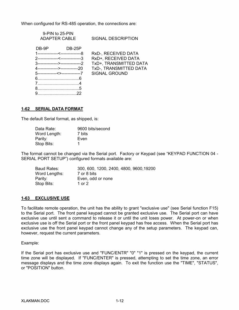
When configured for RS-485 operation, the connections are:
9-PIN to 25-PINADAPTER CABLE SIGNAL DESCRIPTION
DB-9P DB-25P1--------------<--------------8 RxD-, RECEIVED DATA2--------------<--------------3 RxD+, RECEIVED DATA3-------------->--------------2 TxD+, TRANSMITTED DATA4-------------->------------20 TxD-, TRANSMITTED DATA5-------------<>-------------7 SIGNAL GROUND6..................................67..................................48..................................59................................22
1-62 SERIAL DATA FORMAT
The default Serial format, as shipped, is:
Data Rate: 9600 bits/secondWord Length: 7 bitsParity: EvenStop Bits: 1
The format cannot be changed via the Serial port. Factory or Keypad (see “KEYPAD FUNCTION 04 -SERIAL PORT SETUP”) configured formats available are:
Baud Rates: 300, 600, 1200, 2400, 4800, 9600,19200Word Lengths: 7 or 8 bitsParity: Even, odd or noneStop Bits: 1 or 2
1-63 EXCLUSIVE USE
To facilitate remote operation, the unit has the ability to grant "exclusive use" (see Serial function F15)to the Serial port. The front panel keypad cannot be granted exclusive use. The Serial port can haveexclusive use until sent a command to release it or until the unit loses power. At power-on or whenexclusive use is off the Serial port or the front panel keypad has free access. When the Serial port hasexclusive use the front panel keypad cannot change any of the setup parameters. The keypad can,however, request the current parameters.
Example:
If the Serial port has exclusive use and "FUNC/ENTR" "0" "1" is pressed on the keypad, the currenttime zone will be displayed. If "FUNC/ENTER" is pressed, attempting to set the time zone, an errormessage displays and the time zone displays again. To exit the function use the "TIME", "STATUS",or "POSITION" button.
XXLLAAKKMMAANN..DDOOCC 22--11
SECTION II
INSTALLATION
2-1 OVERVIEW
The Model XL-AK Time and Frequency receiver consists of the XL-AK receiver, Antenna unit andcable. The XL-AK is capable of basic operation without any RS-232 connection. Since the standardinternal oscillator is a Temperature Compensated Crystal Oscillator (TCXO), it is essential that it beisolated from rapid fluctuations in air temperature. For this reason, operation with all covers in place isrequired in order to obtain specified stability performance levels. When an optional higher stabilityovenized oscillator is used in the XL-AK, this is not necessary.
2-2 PROCEDURE
Place the XL-AK Antenna unit with an unobstructed view of the sky. Connect the cable between theAntenna unit and XL-AK antenna input connector. If Serial I/O communications are desired, make thenecessary connections to your equipment after referring to the Serial Interface information in manualSection I. The XL-AK-601 will also have display and keypad functionality. These are thoroughlydescribed in manual Section III.
The receiver can be powered by 95-260 VAC or 120-370 VDC. See Section I for specific limits on thevoltage and frequency ranges.
NOTE: The rear panel IEC power receptacle is used for both AC and the Optional High Voltage DCinputs, and is insensitive to polarity.
The power fuse for the AC or DC power input is integral to the internal power supply. Replace withTrueTime part number 363-2.0SB (Littelfuse # 218002).
Connect an appropriate AC or Optional DC power source to the XL-AK receiver via the IEC powerconnector. Within a few seconds, the XL-AK will output elapsed time from power-on via Serial functionF08. (Serial inputs will be ignored until the F08 output is terminated with a CTRL-C character (Hex03).) If satellites are visible, the output time will switch from elapsed time to UTC time within a fewminutes.
If the XL-AK has been placed in AUTO mode via Function 53, the recommended setting for newinstallations, it will not phase lock its internal oscillator to the received time signal until it has computeda 3-D position. You may wait up to 15 minutes for the XL-AK to independently ascertain its position byacquiring four satellites, or you may speed up the process by using Function 50 to enter theapproximate location to an accuracy of 1o (about 100 km) or better.
When the XL-AK has phase locked its oscillator to the GPS signals and has set its 1PPS output to thespecified accuracy, the terminating character of the Serial function F08 continuous time output stringwill change from a "?" to a "space" at this time. If satellites are visible and the XL-AK has an accurateposition, lock should be achieved within three minutes. XL-AK units with optional internal or externalovenized oscillators will require a longer time to lock due to the oscillator warm-up time.
Initially following power-up, the optional open collector alarm output will provide a high impedance toground. When the XL-AK is tracking satellites and is controlling the local oscillator and 1PPS output towithin specified accuracy to UTC, this output will provide a low impedance to ground. Thereafter,
XXLLAAKKMMAANN..DDOOCC 22--22
whenever the XL-AK outputs are not within specifications, this output will provide a high impedance toground.
2-3 SPECIAL CONSIDERATIONS FOR EXTERNAL OSCILLATOR CONTROL OPTION
Interconnection between the XL-AK and the external oscillator to be controlled must be plannedcarefully. Of particular importance is the elimination of ground loops made by the connection of powersupply returns, DAC control voltage return and the signal ground shield. Some types of oscillators areparticularly susceptible to noise in these loops which can cause missing pulses to occur at the XL-AKExternal Oscillator input signal conditioning circuits.
The recommended connection method is as follows:
1) Provide a single ground path between the XL-AK and the External Oscillator.2) Let that single ground provide the DAC tuning voltage return.3) Transformer couple the External Oscillator signal into the XL-AK to break the
coaxial ground connection, thereby eliminating that potential ground loop.
Following these guidelines will provide reliable operation with a wide variety of oscillators.
2-4 RACK MOUNTING
The XL-AK mounts in a standard 19 inch rack system using the rack mounting brackets provided.These brackets may be attached to the sides of the cabinet. First remove the screws from each sideof the instrument. Place the screws supplied with the brackets through the countersunk holes in thebrackets then into the clock and tighten. The unit may now be mounted in a 1-3/4 inch opening in anyEIA Standard 19 inch rack system.

XXLLAAKKMMAANN..DDOOCC 33--11
SECTION III
OPERATION
3-1 INTRODUCTION
The Model XL-AK Time and Frequency Receiver provides extremely accurate TIME and FREQUENCYthat is traceable to the UNITED STATES NAVAL OBSERVATORY (USNO) by use of the NAVSTARGlobal Positioning System (GPS). This section provides a complete description of the operation of theXL-AK. For the Model XL-AK-600, all references to the front-panel keypad and alphanumeric displayshould be ignored as they are only available on the Model XL-AK-601. NOTE: Assembly and/orschematic drawings that may be included in this manual will be identified as 600-100 for the XL-AK-600units and as 600-101 for the XL-AK-601 units. Only Maintenance manuals will include schematicdrawings.
3-2 GENERAL OPERATION
Every effort has been made to make the operation of the XL-AK backwardly compatible with theKeypad and Serial functionality of the GPS-DC and GPS-TMS/TMD products, however somedifferences exist. The three most-used functions (TIME, STATUS and POSITION) have beenassigned to front-panel push buttons. All remaining functions may be accessed via the front-panelkeypad and viewed on a front-panel alphanumeric display or accessed via the Serial port interface andviewed on a monitor. The XL-AK is completely compatible with the Keypad and Serial functionality ofthe XL-DC product.
3-3 XL-AK START-UP
At power up, the unit will present messages on the front panel LCD display to indicate the version ofsoftware installed in the unit, and how to invoke the keypad help function. The first message is theversion of the system software. For example:
TRUETIME Mk IIIsys ver 020
After a few seconds, the display will show:
Press func, 0, 0for help.
Then the display will show the version of the clock-specific software:
GPS-XL V1.036182-6064v004
After a few seconds, the display will show the status display, which will remain until a keypad functionis invoked, or the "TIME" or "POSITION" button is pressed.
It should be noted that the text of the version messages will vary from model to model and version toversion.
XXLLAAKKMMAANN..DDOOCC 33--22
After power up, the XL-AK will send over the Serial port continuous time with a one second updaterate. The format of this output string is described in section 3-208, “SERIAL FUNCTION 08 -CONTINUOUS TIME ONCE PER SECOND ENABLE". Prior to satellite acquisition the time eitherdisplayed or sent over the Serial port is battery-backed GPS time. Once satellite signals are acquired,UTC time is displayed.
Similarly, time is send to the Serial port with local offset and the "?" time quality character will clear to aspace character. Sending a CTRL-C (Hex 03) to the XL-AK Serial port will terminate this continuoustime output mode and allow requesting of other information via the Serial function commands.
The Model XL-AK includes a Red/Green LED on the front panel that provides Status information.Detailed function of the Status LED is described in manual sections 3-173 and 3-273 "REQUEST/SETALARM STATUS/CONTROL". Factory defaults for function 73 produce an ORANGE Status indicationat power up, and a blinking at 1 pulse per second GREEN Status indication after the unit locks.
3-4 SATELLITE ACQUISITION
Time to first satellite acquisition is dependent upon many factors. The following paragraphs describesome of the possible events which affect satellite acquisition times. Note that satellite visibility at thereceiver site will affect acquisition times.
If the Time and Frequency receiver was tracking satellites immediately prior to a momentary powerinterruption, satellite reacquisition will be almost immediate with valid UTC time available within 180seconds.
If the current position is unknown or in error by more than 100 km, acquisition typically requires from 3to 15 additional minutes to locate current antenna position, re-acquire satellite almanac and ephemerisdata, and deliver UTC time. Refer to the AUTO MODE paragraph later in this section for operationaldetails.
If internal battery-backed time and/or almanac data is lost, the time to first satellite acquisition willdepend upon which satellites are visible at the time of power-on. The XL-AK will attempt to acquiresatellites not knowing which satellites are visible. The satellite search will be expanded until a satelliteis acquired. After first satellite acquisition, time will be acquired from the satellite and the receiver willreturn to normal operation. This procedure may take as little as 3 minutes to as long as 15 minutesdepending upon current satellite visibility.
To verify the status of the Model XL-AK-601 receiver, a front panel "STATUS" button has beenprovided. Refer to "STATUS PUSH BUTTON" in this section.
3-5 through 3-9 reserved

XXLLAAKKMMAANN..DDOOCC 33--33
3-10 OPERATIONAL MODES
The XL-AK operates under one of three modes: AUTO, SURVEY and TIME. Each mode is describedbelow. Use Keypad or Serial function 53 to change from one mode to another or to determine thecurrent mode. Refer to "KEYPAD FUNCTION 53 - OPERATIONAL MODE ENTRY/REQUEST" or"SERIAL FUNCTION F53 - OPERATIONAL MODE ENTRY/REQUEST" in this section. The as shippeddefault mode is AUTO. The default on subsequent power-up will be the mode used at the previouspower-down.
3-11 AUTO MODE
AUTO mode offers a painless solution to GPS receiver start-up and operation. Under AUTO mode, nouser input is required to properly complete a XL-AK site installation.
AUTO mode requires a minimum of 4 satellites in order to complete the installation process.
After XL-AK receiver installation or whenever it is desired to reinstall the XL-AK, select AUTO MODE tobegin the installation process.
AUTO mode consists of 3 major processes: 1) Current Position Search, 2) Current Position Averagingand Refinement; and 3) Invocation of Time Mode. Time and Frequency data and output signals areavailable throughout this process, however optimal accuracy and stability are not achieved until step2) has been completed. With good satellite visibility this occurs following about twenty-four hours ofaveraging.
Current Position Search: Immediately after invoking AUTO mode, the XL-AK clears the positionaverage and the GPS core receiver Non-Volatile Random Access Memory (NVRAM) and then begins asatellite search. Since invocation of AUTO mode does clear the average position, the time andfrequency outputs may be disturbed. Care should be taken not to needlessly invoke the AUTOmode.
The satellite search begins with 8 satellites. After several minutes, a second set of satellites issearched. The process continues until a satellite is acquired.
Immediately after acquisition, data lock is attempted and the satellite doppler compensation (thechange in the 1.575 GHz frequency due to the apparent satellite velocity, for terrestrial basedreceivers, typically 0 to +5 KHz) is adjusted until data can be read from the satellite.
After data lock, GPS time is acquired to the 20 mS level of accuracy, and almanac data loading for theentire constellation begins. At this time the Serial function F53 command returns "F53 AUTO: 1 SATS"and the first line of the display indicates "MODE: AUTO 1 SAT", giving the positioning mode of theGPS core unit. The second line indicates "sats ##", giving the Pseudo Random Noise (PRN) numberof the satellite being tracked.
During the data loading process, additional satellites are searched. When a second satellite isacquired and data lock is achieved, the Serial function F53 command returns "F53 AUTO: 2 SATS"and the first line of the display indicates "MODE: AUTO 1 SAT", giving the positioning mode of theGPS core unit. The second line indicates "sats ##", giving the PRN number of the highest satellitebeing tracked. At this time, the position of the XL-AK may be placed in the proper hemisphere,narrowing the search for possible SV's.
XXLLAAKKMMAANN..DDOOCC 33--44
When a third satellite is acquired, a unique position solution exists given an assumed ellipsoid heightnear 0 meters. At this time, the Serial function F53 command returns "F53 AUTO: 3 SATS" and thefirst line of the display indicates "MODE: AUTO 2-D", giving the positioning mode of the GPS core unit.The second line indicates "sats ## ## ##", giving the PRN numbers of the three satellites being used inthe two-dimensional (2-D) fix. With this position, the remaining visible SV's are determined based onthe almanac and the time and are acquired rapidly. Once a 3-D position fix has been determined,synchronization to UTC begins and the first stage of AUTO Mode has almost ended. At this time theSerial function F53 command returns "F53 AUTO: # SATS", where # is the number of SV's beingtracked, which may be as many as 6. The first line of the display indicates "MODE: AUTO 3-D" whilethe second line indicates "## ## ## ## ## ##", giving the PRN numbers for up to six satellites beingtracked.
During the position refinement stage of AUTO mode, the constellation may change such that 3-D fixesare not available. This will be indicated on the status display. Though these 0-D and 2-D fixes will notgo into the position average, they will be used to control the time and frequency outputs of the XL-AK.
Current Position Averaging and Refinement: After completing the first Current Position Search phaseof AUTO mode, AUTO mode automatically begins averaging position fixes, providing an increasinglymore accurate and stable time and frequency reference position. The quality of the timing andfrequency outputs will improve until a terminal average of approximately twenty-four hours duration hasbeen obtained. At this time, the XL-AK returns "F53 TIME: # SATS" in response to the Serial functionF53 command and the first line of the display indicates "MODE: TIME X-D", where X is either 2 or 3depending upon the satellite visibility. As in AUTO mode, the second line of the display indicates thePRN numbers of the current satellites being used in the TIME solutions.
Invocation of TIME Mode: After the position average is complete, the AUTO mode switches the XL-AKto TIME mode and the averaged position will be used for all future timing solutions. TIME mode inhibitsfurther surveying. The auto installation process is concluded.
The XL-AK will remain in TIME mode and will power-up in TIME mode using the averaged positionafter a power outage. However, after powering up in TIME mode, if the computed positionsconsistently differ from the previously stored average position by more than 1 km for a significantperiod of time, the XL-AK will automatically invoke AUTO mode to re-establish the position. Otherwise,operator intervention would be necessary to re-invoke AUTO mode.
3-12 SURVEY MODE
When in the SURVEY operational mode, the XL-AK will repeatedly calculate position and time basedon the unaveraged position. The position solutions are not averaged, and multiple satellite averagingtechniques for reducing the effects of SA on the time solution are not employed. This mode ofoperation is appropriate in dynamic or pseudo-static platform applications. Strictly stationary usersshould use the far more accurate and stable TIME mode. The specified time and frequencyperformance levels may not be met when the XL-AK is operating in SURVEY mode.
There are two choices for SURVEY operation: STATIC and DYNAMIC. STATIC should be used whenthe mode of operation is pseudo-static, i.e. the unit is periodically transported to a new location andthen stationary operation is performed at the new location. In this mode, the GPS core receiver willeasily maintain lock under the dynamics experienced during ground transport and will quickly provideaccurate time and frequency once at the new site. This mode also supports operation with a singlesatellite once the position at the new site has been determined. However, if operation while moving isimportant and the possibility of satellite obstruction exists, STATIC should not be selected aserroneous time and frequency steering data could be used while only a single satellite is visible.

XXLLAAKKMMAANN..DDOOCC 33--55
DYNAMIC should be selected when operation is truly dynamic and might possibly include highacceleration or velocity such as might be experienced on-board tactical aircraft. In this mode, satellitevisibility must be complete and fall-back to single satellite operation is not supported.
3-13 TIME MODE
When in the TIME operational mode, the XL-AK disables updating of the reference position averageand computes timing solutions based on either the previously averaged position or a reference positionwhich has been input via either Keypad or Serial function 56. However, each position fix update istested against the reference position to detect possible relocation of the receiver and antenna duringthe last power off period. If the XL-AK determines that it has been moved by more than 1 km, it willautomatically set itself into the AUTO mode of operation.
Up to six satellites are used for timing solutions, enabling significant reduction of the effects ofSelective Availability on the stability and accuracy of the timing and frequency outputs andmeasurement data. These satellites are chosen to be the highest ones currently available.
3-14 through 3-19 reserved
3-20 TIME QUALITY INDICATION
Whenever the XL-AK is not tracking satellites, the timing accuracy will be dependent upon theaccuracy and stability of the currently selected oscillator (internal or external). Time error accumulatesdepending upon the stability of the oscillator used and the accuracy to which it was set prior to loss ofGPS steering information. The XL-AK continually calculates an estimate of the "worst-case time error".When the receiver is tracking satellite signals and is operating from a known position, the worst-caseerror is 200 ns. If lock with all satellite signals is lost, the Serial function F53 command returns "F53MODE: 0 SATS", where "MODE" is the current operating mode, i.e. AUTO, SURVEY, TIME. If thetime quality indicator character is enabled (see SERIAL FUNCTION 11 - OUTPUT FORMATENTRY/REQUEST) then the time string returned by either Serial function F08 or F09 will indicate theworst-case time error with a different character for each of four thresholds. The user may enable,disable and set these thresholds using Serial function F05. As shipped these indicators are enabledand the default thresholds are:
First threshold - 1 usSecond threshold - 10 usThird threshold - 100 usFourth threshold - 1000 us
New threshold values entered are retained upon power-down and are the new defaults uponsubsequent power-ups.

XXLLAAKKMMAANN..DDOOCC 33--66
3-21 FRONT PANEL INTERFACE
The primary user interface on Model XL-AK-600 is the Serial port (refer to Serial functions). On ModelXL-AK-601, the front panel is the primary user interface. Input is via three front panel push buttonsand a 16-key keypad, output is via a two line 32-character alphanumeric display that provides statusand various function information.
3-22 reserved
3-23 ALPHANUMERIC DISPLAY
The alphanumeric display is used both to display current clock status and as a means ofcommunicating information accessible through the XL-AK list of keypad functions.
When not being used for keypad function operation, the alphanumeric display can be set to display thecurrent clock mode and satellite tracking status or the current time with calendar day and year. Currentposition information is also available but, because it requires several screens to display all of theposition information, current position information is only updated upon subsequent requests.
3-24 TIME PUSH BUTTON
Pressing the TIME push button places the time-of-year and the date on the alphanumeric display. Theformat of the date is day-of-week, month, day-of-month, year.
3-25 STATUS PUSH BUTTON
The Status Push Button is used to place current clock status on the alphanumeric display.
Additionally, PRESSING THE STATUS BUTTON WILL ABORT ANY KEYPAD FUNCTIONCURRENTLY IN PROGRESS. If an incorrect function was entered, or if the alphanumeric displayshows something unexpected, pressing the status push button will abort the function with no actiontaken by the function.
When pressed, the Status Push Button places the current clock mode and satellite tracking status onthe alphanumeric display.
If the clock is not tracking satellites, the display will show:
STATUS: lookingfor Satellites
If the clock has acquired a satellite but has not yet acquired satellite data lock, the display will show:
STATUS: No usablesatellites yet
If the clock has achieved satellite data lock, then the display will show "STATUS:", the current mode("AUTO", "SURVEY", or "TIME"), the position fix mode ("1 sat", "2-D", or "3-D"), and up to six PseudoRandom Noise (PRN) number(s) of the satellite(s) being tracked.

XXLLAAKKMMAANN..DDOOCC 33--77
3-26 POSITION PUSH BUTTON
Pressing the POSITION button will cause the location of the antenna to be displayed. The first timethe POSITION button is pressed the alphanumeric display will show:
LATITUDE N 38 23'55.0"
There may be a delay of several seconds before the latitude appears. This delay is necessary toobtain the current position solution from the core GPS receiver module.
The second time the POSITION button is pressed the display will show:
LONGITUDE W 122 42'56.0"
The third time the POSITION button is pressed, the display will show:
Altitude or Altitude+000050 Meters +000152 Feet
The fourth time the POSITION button is pressed, the display will show:
Pdop+2.06
which is the position dilution of precision (PDOP).
Each press of the POSITION button will cause the display to scroll through these four readings. Theposition that is displayed will change slightly each time it is displayed if the unit has adequate satellitevisibility. Since these positions are unaveraged single fixes their accuracy is limited by both thegeometry of the satellite constellation and the effects of SA. The fixes displayed using this button areequivalent to those returned via either keypad function 50 or Serial function F50.
3-27 KEYPAD OPERATION
The 16-key panel-mounted keypad consists of numeric keys "0" through "9", arrow keys "up", "down","right", and "left", a clear key "CLR" and the function/enter key "FUNC/ENTR". Refer to "SELECTINGFUNCTIONS AND ENTERING DATA" in this section before attempting function entries. The followingrules are for keypad function entry:
A. STATUS, TIME, or POSITION should be on the alphanumeric display before starting a function.If not, press the "STATUS" button.
B. It takes several seconds for some functions to appear. If nothing happens after severalseconds, press "STATUS", then try again.
C. When pressing keypad buttons, hold the button for 1/4 second to reduce contact bounce andinsure the key is recognized. Short "pokes" may result in bad entries.
D. To enter a specific function first press FUNC/ENTR then the function number. Be sure toinclude the leading zeros for functions less than ten. If the function number is currently
XXLLAAKKMMAANN..DDOOCC 33--88
unassigned or not implemented the alphanumeric display will show the "Function notimplemented" message and will then revert to STATUS.
E. When entries are complete and the display shows the desired data, press "FUNC/ENTR".
F. The "CLR" key will clear data entered. Example: If you intended to enter a value of 865, butnotice just prior to pressing the "FUNC/ENTR" that you inadvertently entered 855, press "CLR".The display will revert to the previous value. Re-enter 865 and press "FUNC/ENTR". To verifyyour entry, press "FUNC/ENTR" and the appropriate function number and the data will display.To leave this function unchanged simply press the "STATUS" button. Your entry will remainunchanged and the display will have reverted back to "STATUS".
G. Use the left or right arrow keys to move the cursor beneath the character that you wish to edit.Use the up or down arrow keys to scroll through the possible choices for that character.
3-28 SELECTING FUNCTIONS AND ENTERING DATA
The various keypad functions are listed in the following KEYPAD FUNCTION LIST. Some of thesefunctions are optional and may not be included in your unit. If in doubt as to whether your unit includesa particular function, try it. The alphanumeric display shows the message "Function not implemented"if the function is not in your firmware. NOTE: Most of the functions must be requested to obtain themost current value.
3-29 through 3-98 reserved
XXLLAAKKMMAANN..DDOOCC 33--99
3-99 KEYPAD FUNCTION LIST
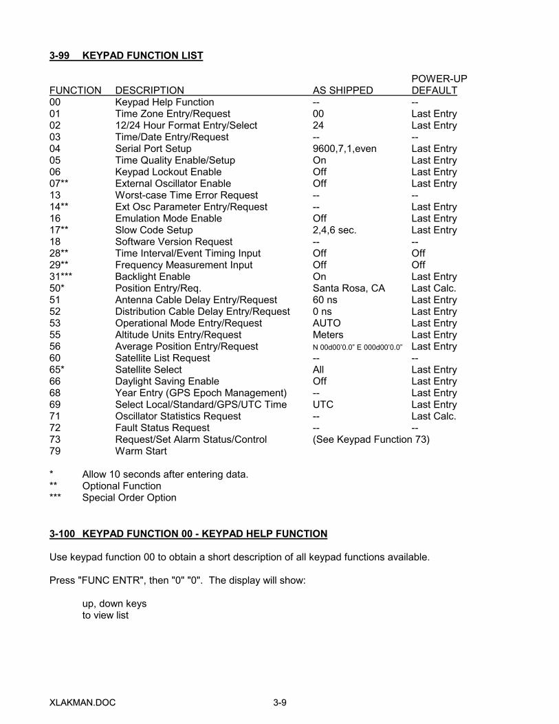
POWER-UPFUNCTION DESCRIPTION AS SHIPPED DEFAULT00 Keypad Help Function -- --01 Time Zone Entry/Request 00 Last Entry02 12/24 Hour Format Entry/Select 24 Last Entry03 Time/Date Entry/Request -- --04 Serial Port Setup 9600,7,1,even Last Entry05 Time Quality Enable/Setup On Last Entry06 Keypad Lockout Enable Off Last Entry07** External Oscillator Enable Off Last Entry13 Worst-case Time Error Request -- --14** Ext Osc Parameter Entry/Request -- Last Entry16 Emulation Mode Enable Off Last Entry17** Slow Code Setup 2,4,6 sec. Last Entry18 Software Version Request -- --28** Time Interval/Event Timing Input Off Off29** Frequency Measurement Input Off Off31*** Backlight Enable On Last Entry50* Position Entry/Req. Santa Rosa, CA Last Calc.51 Antenna Cable Delay Entry/Request 60 ns Last Entry52 Distribution Cable Delay Entry/Request 0 ns Last Entry53 Operational Mode Entry/Request AUTO Last Entry55 Altitude Units Entry/Request Meters Last Entry56 Average Position Entry/Request N 00d00’0.0” E 000d00’0.0” Last Entry60 Satellite List Request -- --65* Satellite Select All Last Entry66 Daylight Saving Enable Off Last Entry68 Year Entry (GPS Epoch Management) -- Last Entry69 Select Local/Standard/GPS/UTC Time UTC Last Entry71 Oscillator Statistics Request -- Last Calc.72 Fault Status Request -- --73 Request/Set Alarm Status/Control (See Keypad Function 73)79 Warm Start
* Allow 10 seconds after entering data.** Optional Function*** Special Order Option
3-100 KEYPAD FUNCTION 00 - KEYPAD HELP FUNCTION
Use keypad function 00 to obtain a short description of all keypad functions available.
Press "FUNC ENTR", then "0" "0". The display will show:
up, down keysto view list

XXLLAAKKMMAANN..DDOOCC 33--1100
Press any key to see the next display:
Func/enter keyto call function
Press any key to see the next display, the first entry in the keypad function description list:
f01: Sets timezone
The list of available keypad functions can be viewed by pressing the up or down arrow keys. Eachentry in the list gives the function number and a short description of the function's purpose. If the"FUNC/ENTR" is pressed, the function being displayed will be invoked. When a function so invoked isfinished, the display will revert to "status".
The help function can be exited without invoking a function by pressing the "TIME", "STATUS", or"POSITION" buttons.
3-101 KEYPAD FUNCTION 01 - TIME ZONE ENTRY/REQUEST
Use function 01 to enter the time-zone offset. The as shipped default is 00:00 (UTC). The default onpower-ups will be the value used before power-down. The Time Zone range is +12:00 to -12:00 hours.
Press "FUNC/ENTR", then "0" "1". The display will show:
Time zone hr:min+00:00
Press the right or left arrow keys to position the cursor beneath the character that you wish to change.Press the up or down arrow keys to scroll through the possible choices. Alternately, directly enter thenumbers using the keypad. When the display shows the desired time-zone offset press "FUNC/ENTR"to enter your choice.
3-102 KEYPAD FUNCTION 02 - 12/24 HOUR FORMAT ENTRY/REQUEST
Use function 02 to select either the 12-hr or 24-hr time display format. The as shipped default is the24-hr format. The power-up default will be whatever the format was before power-down.
Press "FUNC/ENTR", then "0" "2". The display will show:
12/24 hr Format or 12/24 hr Format24 12
Press the up or down arrow keys to toggle between 24 and 12. When the display shows the desiredformat, press "FUNC/ENTR" to enter your choice.

XXLLAAKKMMAANN..DDOOCC 33--1111
3-103 KEYPAD FUNCTION 03 - TIME/DATE ENTRY/REQUEST
Use function 03 to enter or request time and date.
Press "FUNC/ENTR", then "0" "3". The display will show:
Date-time or Date-timeUTC Local
Press the up or down arrow keys to toggle between "UTC" and "Local" depending on which you intendto enter. When the display shows your choice, press "FUNC/ENTR" again and the display will show:
Date-timeMM/DD/YY
where MM is the month, DD is the day and YY is the year. Press the right or left arrow keys to movethe cursor beneath the digit that you wish to change. Press the up or down arrow keys to scrollthrough the possible choices. Alternately, directly enter the numbers using the keypad. The cursor willadvance to the next digit automatically. NOTE: Although an illegal entry will display, the entry will notbe accepted.
Press "FUNC/ENTR" again and the display will show:
Date-timeHH:MM:SS
where HH is the hours, MM is the minutes and SS is the seconds.
Press the left or right arrow keys to position the cursor beneath the digit that you wish to change.Press the up or down arrow keys to scroll through the possible choices. Alternately, directly enter thenumbers using the keypad. The cursor will advance to the next digit automatically. Press"FUNC/ENTR" to enter the data. NOTE: Only valid times will be accepted.
3-104 KEYPAD FUNCTION 04 - SERIAL PORT SETUP
Use function 04 to configure the Serial port. The as shipped default values are:
Baud Rate 9600Data Bits 7Parity evenStop bits 1
The default values on power-ups will be those in use prior to power-down.
Press "FUNC/ENTR, then "0" "4". The display will show:
Ser port setupBaud rate 9600
XXLLAAKKMMAANN..DDOOCC 33--1122
Press the up or down arrow keys to scroll through the possible baud rate choices. When the displayshows the desired baud rate, press "FUNC/ENTR" again and the display will show:
Ser port setupData bits 7
Press the up or down arrow keys to toggle between 7 and 8 data bits choices. When the displayshows the desired choice, press "FUNC/ENTR" again and the display will show:
Ser port setupParity even
Press the up or down arrow keys to toggle between even or odd parity. When the display shows thedesired parity press "FUNC/ENTR" again and the display will show:
Ser port setupStop bits 1
Press the up or down arrow keys to toggle between 1 and 2 stop bits. When the display shows thedesired choice, press "FUNC/ENTR" to enter all Serial port parameters.
3-105 KEYPAD FUNCTION 05 - TIME QUALITY ENABLE/SETUP
Both the front-panel numeric display and the Serial port time output string indicate time quality. Referto NUMERIC DISPLAY earlier in this section for a complete description of the display's time qualityindications. Refer to Serial FUNCTION FO8 - CONTINUOUS TIME ONCE PER SECOND for adescription of the time quality indication in the Serial port time output string. As shipped, time qualityindication is enabled and the thresholds are:
First threshold - 1 uSSecond threshold - 10 uSThird threshold - 100 uSFourth threshold - 1000 uS
The acceptable threshold values are 00000000200 nS to 40000000000 nS.
Use Function 05 to enable or disable the time quality indication or set the worst-case-error thresholds.Press "FUNC/ENTR", then "0" "5". The display will show:
Time quality or Time qualityon off
Press the up or down arrow keys to toggle between "on" and "off". When the display shows thedesired state, press "FUNC/ENTR". The display will show:
First tq flag:00000000000ns
or the current value. Press the right or left arrow keys to position the cursor beneath the digit that youwant to change. Press the up or down arrow keys to scroll through the possible digit choices.Alternately, directly enter the numbers using the keypad. The cursor will advance to the next digit
XXLLAAKKMMAANN..DDOOCC 33--1133
automatically. When the display shows the desired value for the first time quality threshold, press"FUNC/ENTR" and the display will show:
Second tq flag:00000000000ns
or the current value. Using the same combination of arrow keys and direct digit entry, when the displayshows the desired value for the second time quality threshold, press “FUNC/ENTR” and the display willshow:
Third tq flag:00000000000ns
or the current value. Using the same combination of arrow keys and direct digit entry, when the displayshows the desired value for the third time quality threshold, press "FUNC/ENTR" and the display willshow:
Fourth tq flag:00000000000ns
or the current value. Using the same combination of arrow keys and direct digit entry, when the displayshows the desired value for the fourth time quality threshold, press "FUNC/ENTR" and all of the timequality thresholds will be stored.
3-106 KEYPAD FUNCTION 06 - KEYPAD LOCKOUT ENABLE
Use function 06 to enable or disable the keypad. The keypad lock function, when enabled, preventsunauthorized or accidental entries on the keypad. The as shipped default is "off". The default uponsubsequent power-ups will be the same as it was on the previous power-down.
Press "FUNC/ENTR" then "0" "6". The display will show:
Keypad Lock or Keypad Lockon off
Press up or down arrow keys to toggle between "on" and "off". When the display shows the desiredchoice, press "FUNC/ENTR". After the keypad lock is enabled, any attempt to enter a function on thekeypad (except keypad function 06) will result in the message "Keypad locked" or "Function notimplemented".
3-107 KEYPAD FUNCTION 07 - EXTERNAL OSCILLATOR ENABLE (OPTION)
Use function 07 in conjunction with function 14 to enable or disable Phase Locking to an ExternalOscillator. The hardware configuration of the XL-AK must be able to support this function. The asshipped default is "on". The default on power-up will be the same as it was on power-down.

XXLLAAKKMMAANN..DDOOCC 33--1144
Press "FUNC/ENTR" then "0" "7". The display will show:
Ext Oscillator or Ext OscillatorDISabled ENabled
Press the up or down arrow keys to toggle between "Disabled" and "Enabled". When the displayshows the desired choice, press "FUNC/ENTR" to enter your choice.
3-108 through 3-112 reserved
3-113 KEYPAD FUNCTION 13 - WORST-CASE TIME ERROR REQUEST
Use function 13 to display the worst-case time error due to oscillator drift during periods when satellitesare not being tracked.
Press "FUNC/ENTR", then "1" "3". The display will show:
Time errorOver range
if the unit has not yet acquired valid time or:
Time error +00.000 000 200
if the unit is tracking satellites and has acquired valid time.
If the XL-AK acquired valid time but subsequently lost lock to the satellite signals, the time output willbegin to drift. This drift is dependent on the stability of the internal or the optional external oscillatorand the accuracy to which it had been set on frequency prior to the outage. The stability of the optionalexternal oscillator must be entered using Keypad or Serial function 14. The processor calculates anddisplays in seconds the worst-case time based on the stability of the oscillator in use.
3-114 KEYPAD FUNCTION 14 - EXTERNAL OSCILLATOR PARAMETER ENTRY/REQUEST(OPTION)
If the external oscillator is enabled (function 07), the parameters of the external oscillator are used tocalculate the control coefficients as well as the worst-case time error as described by function 13. UseKeypad function 14 or Serial function F14 to set or determine the parameters of the external oscillator.The default on power-up will be whatever the values were at power-down.
Press "FUNC/ENTR" then "1" "4". The display will show:
External OscFREQ _1 MHz
XXLLAAKKMMAANN..DDOOCC 33--1155
Press the up or down arrow keys to select either 1, 5 or 10 MHz as the input frequency of the externaloscillator. Press "FUNC/ENTR" to enter your choice. Now the display will show:
Ext Osc TUNINGSLOPE +1.00e-06
Press the up or down arrow keys to toggle the sign of the external oscillator voltage control tuningslope which is entered in units of fractional frequency offset per volt. Press the right arrow key to moveto the next digit. Either press the up or down arrow keys or alternately, directly enter numbers from thekeypad for each of the remaining digits. The cursor will automatically advance to the next positionwhen a number is entered directly. When the display shows the desired choice, press "FUNC/ENTR"to enter your choice. Now the display will show:
Ext Osc DACNOMINAL 0.50
Press the up or down arrow keys or directly enter the values desired for each digit to set the initialstarting value of the external oscillator control voltage. The number input here sets the decimalfractional value of the full scale DAC output voltage swing to be used for the initial control voltagesetting. The control voltage output may be configured to be either 0 to +10 Volts or -5 to +5 Volts viajumper JP5 on the 87-8XX GPS-XL board. Valid input range is 0.00 to 1.00. Once the desired valuehas been set, press "FUNC/ENTR". The display will show:
Ext Osc TEMPSTAB 5.00e-10
Using the same combination of arrow keys and direct digit entry, set the 0° to 60° C temperaturestability of the external oscillator that is being controlled.
This value is used by the XL-AK to determine the optimal control loop averaging time so thatperformance under environmental stress of up to 8.3° C per hour temperature change does notdegrade the output frequency stability significantly below that of the GPS system stability.
Inputting of better or worse temperature stability than the external oscillator actually has allowsadjustment by the user of the control loop averaging time being used. This may be desirable when theuser knows that the environment differs significantly from the rather stringent 8.3° C per hourassumption made by the XL-AK.
As an example, if the environment is known to exhibit maximum temperature changes on the order of1° C per hour and the user would desire more filtering of the de-stabilizing effects of SA from theoutputs of the XL-AK, a smaller value for the temperature stability of the external oscillator could beentered. The control loop averaging time would then be lengthened relative to the default averagingtime assuming the true temperature stability were entered, by the square root of the ratio of the truetemperature stability divided by the temperature stability actually entered.
After pressing "FUNC/ENTR" to set the external oscillator temperature stability, the display will show:
Save Ext OscParameters? No
Use the up or down arrow key to toggle the desired action and press "FUNC/ENTR". The externaloscillator parameters have now been saved to NVRAM and will be used immediately if the External
XXLLAAKKMMAANN..DDOOCC 33--1166
Oscillator has already been enabled via Keypad function 07 or Serial function F07. Otherwise they willbe used when the external oscillator is next enabled.
3-115 reserved
3-116 KEYPAD FUNCTION 16 - EMULATION MODE ENABLE
Use Keypad function 16 to enable or disable the emulation mode. When the emulation mode is "off",the Serial port responds to the "Mark III command set" as described in this section. When theemulation mode is "on", the Serial port responds to the "Mark II command set" as described in thissection under SERIAL EMULATION COMMANDS. The emulation mode cannot be enabled or disabledvia the Serial port.
The Mark II command set is composed of selected commands used on earlier TrueTime synchronizedclocks. Therefore, most Serial programs written for use with these earlier models may be used withthe current Mark III.
When the emulation is enabled or disabled, the Serial port will change modes, even if waiting tocomplete a command. When emulation mode is turned on, or power is applied when emulation is "on",the Serial port will enter MODE C, continuous time once per second, and the default format will be ineffect. When emulation mode is turned off or power is applied to the unit when emulation is "off", theSerial port will enter the F08 command and send time once per second.
When emulation is "on", the Serial port acknowledges the commands C, T, F, and R. The as shippeddefault is "off". The default on power-up is whatever it was just before power-down.
Press "FUNC/ENTR" then "1" "6". The display will show:
Emulation mode or Emulation modeoff on
Press the up- or down-arrow keys to toggle between "off" and "on". When the display shows thedesired choice, press "FUNC/ENTR" and the command set will change.
3-116.1 SERIAL PORT EMULATION COMMANDS
As a convenience to our customers the TrueTime XL-AK emulates most of the Serial port commandsof the older GPS-DC Mark II GPS Synchronized Clock. Most customer programs written to interfacewith the Mark II Serial port will also interface with the XL-AK Serial port if the emulation mode isenabled with Keypad function 16. Refer to the following Table for the available emulation modecommands.
XXLLAAKKMMAANN..DDOOCC 33--1177
EMULATION MODE COMMANDS:
COMMAND MODE DESCRIPTION
C Mode C Continuous time, once per secondF Mode F Format Time MessageR Mode R Reset to default time format and Mode CT Mode T Time on request
When the emulation mode is enabled with Keypad function 16, the Serial output defaults to Mode C. Ifthe unit was in the emulation mode at power-down, it will power up in the emulation mode and defaultto Mode C. If the operator uses FUNCTION 03 to enter time before it appears on the front paneldisplay, then the entered time will output at the Serial port.
3-116.2 MODE C - CONTINUOUS TIME, ONCE PER SECOND
Use Mode C to set the Serial port to output the time message once each second. Mode C is thepower-up default. To request Mode C send the ASCII character C to the Serial port. The format of theoutput string may be changed with Mode F. The default output string format is:
<SOH>DDD:HH:MM:SSQ<CR><LF>
where:
<SOH> = ASCII start-of-header character (Hex 01).DDD = ASCII colon character.HH = two-digit hours.MM = two-digit minutes.SS = two-digit seconds.. = ASCII period character.mmm = three characters for milliseconds.Q = time quality character (see following).<CR> = ASCII carriage return character.<LF> = ASCII line feed character.
The time quality character may be one of the following:
SPACE which indicates a worst-case error less than threshold 1.. which indicates a worst-case error greater than or equal to threshold 1.* which indicates a worst-case error greater than or equal to threshold 2.# which indicates a worst-case error greater than or equal to threshold 3.? which indicates a worst-case error greater than or equal to threshold 4.
The time quality character prior to satellite signal acquisition will be "?". Refer to SERIAL FUNCTIONF13 - WORST-CASE TIME ERROR REQUEST for an explanation of worst-case error. The carriagereturn character <CR> start bit begins on the second, +0 to +1 bit period or +1 ms, whichever is larger.
To halt the output of time once each second send another command character to the Serial port. Non-command characters will be ignored if sent to the Serial port. If the command character C is sent tothe Serial port prior to acquisition of time of year, then the port will output time elapsed from power-uponce each second. Once correct time has been acquired, the port will output time of year.

XXLLAAKKMMAANN..DDOOCC 33--1188
3-116.3 MODE F - FORMAT THE TIME MESSAGE
Use Mode F to alter the format of the time output string used in Mode C and Mode T. To set theformat send a string of the form:
FDDD<C1>HH<C2>MM<C3>SS<C4>mmmQ
where:
F = Mode F command.DDD = three characters for days.<C1> = character that will be transmitted between the days and hours.HH = two characters for hours.<C2> = character that will be transmitted between the hours and minutes.MM = two characters for minutes.<C3> = character that will be transmitted between the minutes and
seconds.SS = two characters for minutes.<C4> = character that will be transmitted between the seconds and
milliseconds.mmm = three characters for milliseconds.Q = single character for the time quality.
If an X is used as a character in any character position, including the time quality character position,that position and its data will be omitted from the format. Any other character except a mode commandcharacter enables that position in the format.
There are no character transmissions until formatting is terminated. There are three ways to terminateformatting: 1) If a command character is sent before completing the format string, the altered portionof the format is accepted and the remainder of the format is unchanged and the new mode is entered.2) If an ASCII line feed character (Hex 0A) is sent before completing the format string, the alteredportion of the format is accepted and the remainder of the format uses the default and the time isimmediately output once in the new format. 3) If all 15 characters of the format string are entered, theport will immediately output time once in the newly selected format. This new format will be used fortime output in both Mode C and Mode T.
Note that the milliseconds are not available in Mode C even though formatted. On power-up the formatwill revert to the default format. Further note that the response of F mode is only accurate to about +1sec and is intended only to indicate the current format, not to provide time information.
Sample Entry: F123/12:34:66.789QResponse: <SOH>360/22:01:25.602*<CR><LF>
Sample Entry: FXXX hh,mm,ss XXXXResponse: <SOH> 22,01,25 <CR><LF>
Sample Entry: FDDDAXXTResponse: <SOH>360A:01:25.602*<CR><LF>
XXLLAAKKMMAANN..DDOOCC 33--1199
3-116.4 MODE R - RESET TO DEFAULT AND MODE C
Use Mode R to reset to the default format and return to Mode C. Send the command character R tothe Serial port and the port will respond by outputting time in the default format once per second. Anyprevious Mode F format is canceled.
The data and carriage return timing of the initial output string sent immediately following the commandcharacter R is not reliable. This is due to internal synchronization with the data rate.
3-116.5 MODE T - TIME ON REQUEST
Use Mode T to request a single output of time to the nearest millisecond. Send the commandcharacter T to the Serial port. The unit will save the time of year as of 9 bits after the center of the startbit of the character T, then the port will immediately respond with a single time data string in the currentformat selected. The Serial port outputs no further data until it receives another command character.The format of the Mode T string may be altered using Mode F. The default format is:
<SOH>DDD:HH:MM:SS.mmmQ<CR><LF>
where:
<SOH> = ASCII start-of-header character (HEX 01).DDD = three-digit day of year.: = ASCII colon character.HH = two-digit hours.MM = two-digit minutes.SS = two-digit seconds.. = ASCII period character.mmm = three characters for milliseconds.Q = time quality character as described below.<CR> = ASCII carriage return character.<LF> = ASCII line feed character.
The time quality character may be a:
SPACE which indicates a worst-case error less than threshold 1.. which indicates a worst-case error greater than or equal to threshold 1.* which indicates a worst-case error greater than or equal to threshold 2.# which indicates a worst-case error greater than or equal to threshold 3.? which indicates a worst-case error greater than or equal to threshold 4.
If a command character T is sent to the Serial port prior to the acquisition of time, the Serial port willoutput time elapsed from power-up.
3-117 KEYPAD FUNCTION 17 - SLOW CODE SETUP (OPTION)
Use function 17 to control the Slow Code output. This output provides one pulse per minute, primarilyfor placing timing marks on drum recorders. Each pulse edge is aligned to within a few nanosecondsof the 1PPS output, with the rising edge at the start of a minute. The as shipped default values are:
XXLLAAKKMMAANN..DDOOCC 33--2200
Once per minute pulse 2 seconds long.Once per hour pulse 4 seconds long.Once per day pulse 6 seconds long.
The default values on power-up will be those in use just prior to power-down.
Press "FUNC ENTR", then "1" "7". The display will show:
Slow Code minutepulse 02 sec
or a different number of seconds. This means that the once per minute slow code pulse will be 2seconds long. Press the right or left arrow keys to position the cursor beneath the digit that you wantto edit. Press the up or down arrow keys to scroll through the possible digit choices. Alternatively,directly enter the numbers using the keypad. The cursor will advance to the next digit automatically.When the display shows the value that you desire for the minute pulse width, press "FUNC/ENTR" andthe display will show:
Slow Code hourpulse 04 sec
or a different number of seconds. This means that the once per hour slow code pulse will be4 seconds long. Using the same combination of arrow keys and direct digit entry, when the displayshows the desired value for the hour pulse width, press "FUNC/ENTR" and the display will show:
Slow Code daypulse 06 sec
or a different number of seconds. This means that the once per day slow code pulse will be 6 secondslong. Using the same combination of arrow keys and direct digit entry, when the display shows thedesired value for the hour pulse width, press "FUNC/ENTR." The display will return to the statusdisplay, completing the entry of the slow code pulse widths.
If the function is aborted by pressing the TIME, STATUS, or POSITION keys before the third press ofthe "FUNC/ENTR" key, none of the changes will take effect.
Any of the 3 pulses may be set for widths between 0 and 59 seconds. A value of 0 means that thepulse will be absent from the Slow Code output.
3-118 KEYPAD FUNCTION 18 - SOFTWARE VERSION REQUEST
Use keypad function 18 to obtain information about the current version of the software installed in theunit.
Press "FUNC/ENTR", then "1" "8". The display will show, for example:
TRUETIME Mk IIIsys ver 020

XXLLAAKKMMAANN..DDOOCC 33--2211
Press any of the arrow keys, to change the display to the clock-specific version. For example:
GPS-XL V1.036182-6064v004
Repeated presses of the arrow keys will switch back and forth between the two displays.
The example shown indicates that the system software is version 20, the GPS-XL version is 1.036 andthe clock-specific software is PART NO. 182-6064 version 004.
To return to the status display, press the "FUNC/ENTR”, or the "STATUS" button.
3-119 through 3-127 reserved
3-128 KEYPAD FUNCTION 28 - TIME INTERVAL/EVENT TIMING INPUT (OPTION)
Refer to manual Section 1-41 for specifications on the Time Interval/Event Timing Input. Use thisfunction to measure the relationship of either periodic or randomly occurring events to the internal timeof the XL-AK.
The Time Interval (TI) mode is best suited to periodic events such as measuring an externally applied1PPS input. In this mode the reported time interval is expressed as the fractional part of a secondbetween the XL-AK 1PPS which starts the count and the external 1PPS which stops it.
The Event Timing (ET) mode is suited to randomly occurring events whose time of occurrence isneeded to a high accuracy. In this mode, the reported event time is expressed as a complete day-of-year through nanoseconds timetag.
Press "FUNC/ENTR", "2","8". The display will show:
Select TI or ETTime Interval
Press the up or down arrow key to toggle between the two modes of operation. When the desiredmode is displayed, press "FUNC/ENTR" to set it. The display will show one of these formats for themeasurements:
TI:.123456789
or
ET: 123:24:12:60.123456789
Pressing "FUNC/ENTR" will abort measurement and return to the previous menu allowing selection ofthe TI/ET mode. Pressing any of these keys will abort the TI/ET function: "TIME", "STATUS" or"POSITION".

XXLLAAKKMMAANN..DDOOCC 33--2222
3-129 KEYPAD FUNCTION 29 - FREQUENCY MEASUREMENT INPUT (OPTION)
Refer to manual Section 3-229 "SERIAL FUNCTION F29 - FREQUENCY MEASUREMENT INPUT(OPTION)" for a detailed operating description of this function. The keypad version offers a sub-set ofthe capabilities available in the Serial function version.
This function allows the user to set up periodic high resolution fractional frequency offsetmeasurements of an externally applied 1, 5 or 10 MHz input relative to the GPS disciplined internal orexternal oscillator. These measurements are then displayed at the user set interval until another key ispressed.
Press "FUNC/ENTR", "2","9". The display will show:
External Freq10 MHz
Use the up or down arrow keys to select the correct input frequency for the XL-AK to measure. Press"FUNC/ENTR" to enter the selection. The display will now show:
Meas Interval000001 sec
Use a combination of right and left arrow keys and either the up and down arrow keys or direct digitentry to set the frequency measurement interval. Press "FUNC/ENTR" to enter the selection. Aftercompletion of the first measurement, the display will show:
Ext Freq XX:XX:XX+x.xxxxxxxxxe-xx
where XX:XX:XX is the time stamp of the endpoint of the displayed measurement and +x.xxxxxxxxe-xxis the fractional frequency offset measurement. These measurements will continually be displayed atthe interval selected until any of these keys is pressed: "FUNC/ENTR", "TIME", "STATUS", or"POSITION".
3-130 reserved
3-131 KEYPAD FUNCTION 31 - BACKLIGHT ENABLE (OPTION)
Use function 31 to turn "on" or "off" the display back light. The as shipped default is "on". The defaulton power-up is whatever it was before power-down. The backlight is standard on the alphanumericdisplay, however, the backlight control is optional and may not be enabled on your particular unit.
Press "FUNC/ENTR" then "3" "1". The display will show:
Backlight or Backlightoff on
Press the up or down arrow keys to toggle between "off" and "on". When the display shows thedesired choice, press "FUNC/ENTR" and the backlight will respond.
3-132 through 3-149 reserved
XXLLAAKKMMAANN..DDOOCC 33--2233
3-150 KEYPAD FUNCTION 50 - POSITION ENTRY/REQUEST
Use keypad function 50 to enter or request the current antenna position. Since function 50 returns themost recent fix computed by the GPS core receiver, not the long term averaged position which iscalculated during the AUTO mode of operation and reported via either Keypad or Serial function 56, itsuse is mainly for initializing the approximate position of the GPS core receiver at new installations orafter loss of non-volatile RAM back-up power.
The as shipped default for position is that of the TrueTime factory in Santa Rosa, California. Theposition on subsequent power-ups will be the same as it was on the previous power-down.
Press "FUNC/ENTR", then "5" "0". The display will show:
LatitudeN 38 23'53.9"
Press the right or left arrow keys to position the cursor beneath the character that you want to change.Press the up or down arrow keys to scroll through the possible choices. Alternately, numbers may bedirectly entered using the keypad. The cursor will automatically advance to the next position. Whenthe display shows the desired Latitude, press "FUNC/ENTR" and the display will show:
LongitudeW 122 42'53.0"
Using the same combination of arrow keys and direct digit entry, when the display shows the desiredvalue for Longitude, press "FUNC/ENTR" and the display will show:
Altitude+000055 Meters
Using the same combination of arrow keys and direct digit entry, when the display shows the desiredvalue for Altitude, press "FUNC/ENTR" and all of the new position data will be entered. To abortwithout changing the initial position data, press the "STATUS" button any time before the final"FUNC/ENTR". If the user attempts to enter a value that is out of the acceptable range the display willshow the message:
Value error!re-enter
and the user will be given a chance to re-enter the correct position value.
3-151 KEYPAD FUNCTION 51 - ANTENNA CABLE DELAY ENTRY/REQUEST
Use function 51 to request or enter a fixed delay to compensate for the antenna cable. The as shippeddefault is +60 nS. When the downconverted antenna is being used, 200 nS should be subtractedfrom the cable delay entered here. The value is held in NVRAM.

XXLLAAKKMMAANN..DDOOCC 33--2244
Press "FUNC/ENTR", then "5" "1". The display will show:
Cable delay+000000060 nS
Press the right or left arrow keys to position the cursor beneath the digit that you want to change.Press the up or down arrow keys to scroll through the possible choices. Alternately, numbers may bedirectly entered using the keypad. The cursor will automatically advance to the next position. Whenthe display shows the desired antenna cable delay, press "FUNC/ENTR" to enter the data. Theacceptable range of delays is from +001000000ns to -001000000ns. Positive delays entered here willadvance the XL-AK timing outputs while negative delays will retard them.
3-152 KEYPAD FUNCTION 52 - DISTRIBUTION CABLE DELAY ENTRY/REQUEST
Use function 52 to request or enter a fixed delay to be used for compensating the timing outputs fordistribution cable delays between the XL-AK and the point of use of the timing signals. Antenna cabledelay compensation should not be performed using this function. Use function 51 for antenna cabledelay. The default is 0 nS. The value is held in NVRAM.
Press "FUNC/ENTR", then "5" "2". The display will show:
Cable delay+000000000 nS
Press the right or left arrow keys to position the cursor beneath the digit that you wish to change.Press the up or down arrow keys to scroll through the possible choices. Alternately, numbers may bedirectly entered using the keypad. The cursor will automatically advance to the next position. Whenthe display shows the desired delay, press "FUNC/ENTR" to enter the data. The acceptable range ofdelays is from +001000000ns to -001000000ns. Positive delays entered here will advance the XL-AKtiming outputs while negative delays will retard them.
3-153 KEYPAD FUNCTION 53 - OPERATIONAL MODE ENTRY/REQUEST
Use function 53 to select the operating mode, either AUTO, SURVEY or TIME. These operatingmodes are explained in detail at the beginning of this section. The as shipped default is AUTO mode.The default on power-up is the mode in use before power-down.
Press "FUNC/ENTR", then "5" "3". The display will show:
AUTO / TIME ModeAUTO
Press the up or down arrow keys to scroll through the possible operating modes. When the displayshows the desired mode, press "FUNC/ENTR" to enter your choice.
When the optional SURVEY mode of operation is available and is selected, either the STATIC orDYNAMIC sub-mode of SURVEY operation must be selected, the display will show:
Dynamic ModeSTATIC
XXLLAAKKMMAANN..DDOOCC 33--2255
Press the up or down arrow keys to scroll through the possible SURVEY operating sub-modes. Whenthe display shows the desired sub-mode, press "FUNC/ENTR" to enter your choice.
3-154 reserved
3-155 KEYPAD FUNCTION 55 - ALTITUDE UNITS ENTRY/REQUEST
Use function 55 to select the units that altitude will be expressed in, either feet or meters. The asshipped default is meters. The default on power-ups is whatever unit was in use at power-down.
Press "FUNC/ENTR", then "5" "5". The display will show:
Altitude mode or Altitude modeMeters Feet
Press the up or down arrow keys to toggle between "Meters" and "Feet". When the display shows thedesired units of measure, press "FUNC/ENTR" to enter your choice.
3-156 KEYPAD FUNCTION 56 - AVERAGE POSITION ENTRY/REQUEST
Use keypad function 56 to enter or request the averaged, hence accurate, current antenna position.Its main use is to provide a means of setting an accurate, surveyed position for use in the TIME modeof operation. Positions provided to the XL-AK via function 56 should be more accurate than 10 meters,otherwise better results may be obtained via AUTO mode, unless satellite visibility at the site is toopoor to provide three dimensional positioning.
The as shipped default position is N 00d00’0.0” E 000d00’0.0”. The position on power-up will be thesame as it was on power-down. An averaged position returned via function 56, which subsequentlybecomes in error by more than 1 km, either due to transport of the receiver and antenna or error in theinitial entry, will be cleared and recalculated automatically once positioning begins at the new site andthe error is detected.
To determine or modify the present position press "FUNC/ENTR", "5","6" and the display will show:
Averager Count or Entered AverageXXXXX/90000 Position
Indicating either that the present average position is based on XXXXX position fixes, and that 90000such fixes will be averaged to complete the accurate position determination or that the currentaveraged position was entered. Press "FUNC/ENTR" again to display:
Ave. LatitudeN DD MM'SS.S"
By pressing a combination of arrow keys and/or direct digit entry, this latitude may be changed. Whenit is as desired, press "FUNC/ENTR" to display:
Ave. LongitudeW DDD MM'SS.S"
XXLLAAKKMMAANN..DDOOCC 33--2266
By pressing a combination of arrow keys and/or direct digit entry, this longitude may be changed.When it is as desired, press "FUNC/ENTR" to display:
Ave. Altitude+XXXXXX Meters
By pressing a combination of arrow keys and/or direct digit entry, this height above the WGS-84ellipsoid may be changed. When it is as desired, press "FUNC/ENTR" to display:
Enter averageposition? No
This choice will only be made available if the XL-AK is operating in the TIME mode. Use the up ordown arrow key to toggle to the desired response and press "FUNC/ENTR" to either cancel entry orcomplete it.
3-157 through 3-159 reserved
3-160 KEYPAD FUNCTION 60 - SATELLITES LIST REQUEST
Use function 60 to list tracked or bad satellites and to see the relative signal strength of the trackedsatellites.
Press "FUNC/ENTR", then "6", "0". The display will show:
List sats:Tracked
Press the up or down arrow keys to toggle between "Tracked" and "Bad". Once the type of list hasbeen selected, press "FUNC/ENTR" again. The display will show:
Tracked Sats: or Bad Sats:#14 +13.65 #14
depending on which list was requested. Some other Satellite number may display. When observingTracked Sats the number following the satellite number is the relative signal strength of that satellite.Each time "FUNC/ENTR" is pressed the display will show the next Tracked or Bad Satellite number.When the list is complete the display will show:
Tracked sats: or Bad sats:End of list End of list
Press "FUNC/ENTR" again and the display will show the initial display. Press the "STATUS" button toexit function 60.
3-161 through 3-164 reserved

XXLLAAKKMMAANN..DDOOCC 33--2277
3-165 KEYPAD FUNCTION 65 - SATELLITE SELECT
Use function 65 to select specific satellites for the receiver to track and to deselect satellites, i.e.instruct the XL-AK to ignore certain satellites. Selections will be retained in non-volatile memory.Press "FUNC/ENTR", then "6" "5". The display will show:
Sat# 14 or Sat# 14Enabled Disabled
or some other satellite number. Press the up or down arrow key to toggle between "Enable" and"Disable". When the display shows the desired choice press "FUNC/ENTR". Each time "FUNC/ENTR"is pressed the display will show the next satellite and whether it is enabled or disabled until all satellitesfor which the GPS core receiver has data are displayed. Then the display will show:
End PressEnter to confirm
Press "FUNC/ENTR" to enter your selections. To abort without changing the status of the satellitespress the "STATUS" button.
3-166 KEYPAD FUNCTION 66 - DAYLIGHT SAVING ENABLE
Use function 66 to set the Daylight Saving Time entry and exit times. The as shipped default is "Off".The default on power-up will be the selection in use just prior to power-down.
Press "FUNC/ENTR", then "6" "6". The display will show:
Daylight Saving or Daylight SavingOff Manual
Press the up or down arrow key to scroll between the choices. When the display shows the desiredchoice press "FUNC/ENTR" to enter your choice.
The display and all other time outputs indicate UTC without any DST adjustment if a time-zone offset of00:00 is selected. Regardless of the time-zone offset there will be no DST adjustment if "Off" isselected for the DST function. Some local jurisdictions enter and leave DST at times other than thoseset by U.S. federal law. Therefore, TrueTime has included a "Manual" choice which allows the user tooverride the times of entry into and exit from DST by selecting his own. If "Manual" is selected for theDST function, the display will show:
Enter dst: 02:001st Sun in Apr
or some other entry time and date. Press the right- or left-arrow keys to position the cursor beneaththe character that you wish to change. Press the up- or down-arrow keys to scroll through the possiblechoices. Alternatively, directly enter the numbers using the keypad. The cursor will automaticallyadvance to the next position. The hours may range from 0 to 23. The week may be "1st", "2nd", "3rd","4th", or "Last". Any day of the week or month may be selected. The above display means thatDaylight Saving Time will start at 2 a.m. local time on the first Sunday in April each year. DSTtransitions may be set to occur at any hour of the day, any day of the week or any month of the yearwith the following restriction: If either transition is less than 24 hours from the start or end of a year, thetransition may not occur at the desired time.
XXLLAAKKMMAANN..DDOOCC 33--2288
When the display shows the desired entry time and date, press "FUNC/ENTR" again, and the displaywill show:
Leave dst: 02:00Last Sun in Oct
or some other entry time and date. Press the right or left arrow keys to position the cursor beneath thecharacter that you wish to change. Press the up or down arrow keys to scroll through the possiblechoices. Alternatively, directly enter the numbers using the keypad. The cursor will automaticallyadvance to the next position. The ranges are the same as before but the exit time must be later thanthe entry time otherwise DST will never be entered. When the display shows the desired exit time,press "FUNC/ENTR" to enter the selections. The data entry may be aborted at any time prior topressing the last "FUNC/ENTR" by pressing either the "TIME", "STATUS", or "POSITION" keys.
Once the entry and exit times are entered, they will be retained in nonvolatile memory if the clock losespower or is turned off. If the nonvolatile memory is corrupted due to battery failure or any other cause,the entry time will default to 2:00 a.m. on the first Sunday in April and the exit time will default to 2:00a.m. on the last Sunday of October.
The sequence of the count upon entry into DST is:
01:59:5801:59:5903:00:0003:00:01
assuming the entry time was 2:00 a.m.. The sequence upon exit from DST is:
01:59:5801:59:5901:00:0001:00:01
assuming the exit time was 2:00 a.m.
If the DST function is enabled or disabled when DST is already in effect, the display will take severalseconds to respond. Each time zone transitions into and out of Daylight Saving Time independently.This means that if the current time zone just entered DST and the time zone offset is then changed bymeans of keypad function 01 to a time zone in which the local time of the transition has not yetoccurred, the standard time for that zone will be displayed. If the original time zone setting is restored,its time will remain in DST.
3-167 reserved
3-168 KEYPAD FUNCTION 68 - YEAR ENTRY (GPS EPOCH MANAGEMENT)
The GPS week number sent from the satellites has only 10 bits of precision, so that 1024 weeks fromJanuary 6, 1980 (GPS week 0) it rolls back to 0. To correctly calculate calendar dates after this rollpoint, firmware keeps track of the current year so that it can construct an absolute, non-rolling weeknumber since January 6, 1980.

XXLLAAKKMMAANN..DDOOCC 33--2299
The firmware has the current year embedded in code, and will properly handle dates through the year2015. In addition, as the clock advances to each new year, the current year is updated and used infuture calendar calculations, thus calculations beyond 2015 are handled properly. No user interventionis required as long as the current year saved in non-volatile memory is intact, and so long as the clockruns locked to GPS at least once each 5 years to allow the year to be updated. If after 2015, thecurrent year saved in non-volatile memory is lost, or the clock is not locked to GPS within 5 years ofthe last year saved in non-volatile memory, then Function 68 can be used to manually enter the currentyear. Years prior to 1996 are not accepted, and entering a future year may cause incorrect calendardate calculations.
To request the current year setting via Keypad Function 68, perform the following steps.
Press "FUNC/ENTR" "6" "8" and the display will show:
Set current year_1996
The year displayed will be the year saved in non-volatile memory used in the calendar calculations. Tochange it, enter the current year, then press "FUNC/ENTR". The display will prompt with:
Save year?No
To save, use the up arrow key to change "No" to "Yes", then press "FUNC/ENTR".
3-169 KEYPAD FUNCTION 69 - SELECT LOCAL/STANDARD/GPS/UTC TIME
Use function 69 to select between LOCAL, STANDARD, GPS or UTC time. The selected time type willbe displayed and sent out on the IRIG-B and Serial ports. The as shipped default is the UTC timeformat. The power-up default will be whatever mode was selected prior to power-down.
Description of the various time types:
GPS: The time determined by primary atomic frequency standards. This type of time does notinclude leap seconds. Therefore, it differs from UTC time.
UTC: Universal Time Coordinated. This time is related to the local solar mean time atGreenwich Meridian. This time is adjusted once in a while to compensate for earth’srotational variations.
STANDARD: This time equals UTC plus the local time zone offset.
LOCAL: This time equal STANDARD plus Daylight Saving Time offset, when required.
Standard and Local times require the proper setting of the time zone offset (Function 01). In addition,Local time requires that Daylight Saving Time be properly set (Function 66), if applicable. The 12/24hour mode (Function 02) is applied to all the above time types (GPS, UTC etc.).
Press “FUNC/ENTR”, then “6” “9”. The display will show:
Select Time Type<Time Type>
XXLLAAKKMMAANN..DDOOCC 33--3300
where <Time Type> is either LOCAL, STANDARD, GPS or UTC.
Press the up or down arrow keys to toggle between LOCAL, STANDARD, GPS and UTC. When thedisplay shows the desired format, press “FUNC/ENTR” to enter your choice.
3-170 reserved
3-171 KEYPAD FUNCTION 71 - OSCILLATOR STATISTICS REQUEST
Use keypad function 71 to request the internal or external (when operating in the optional ExternalOscillator enabled mode, see Function 07) oscillator's phase, frequency offset, drift rate and DACvalue. The phase is the instantaneous error in seconds between the oscillator and the control loopzero servo point as reported by the core GPS module. The frequency offset is computed using anaveraging time that is equal to the effective averaging time of the oscillator controller. The oscillatordrift rate is computed using a 24 hour average and is the daily drift rate of the oscillator. The oscillatorDAC value is the signed 16 bit integer which controls the DAC output voltage. It ranges from 32767 to-32768.
"Oscillator phase" is the instantaneous error between the XL-AK timing outputs and GPS. Press"FUNC/ENTR" "7" "1" and the display will show:
Osc Phase-5.788e-09 s
indicating that the XL-AK timing was most recently reported to be approximately 6 nanoseconds late.This number has the full effects of Selective Availability superimposed upon it. The oscillator controlloop servos the mean of this number to zero.
"Oscillator offset" is the frequency offset or error with respect to the GPS frequency. Press"FUNC/ENTR" and the display will show:
Osc Offset-2.150e-11
indicating that the internal or external oscillator frequency is less than GPS by approximately 2 parts in10-11.
"Oscillator drift" is the change in oscillator frequency per day. Press "FUNC/ENTR" again and thedisplay will show:
Osc Drift3.990e-12/DAY
indicating that the internal or external oscillator frequency is changing positively with respect to GPS byapproximately 4 parts in 10-12 per day.
"Oscillator DAC" is the signed 16 bit DAC control integer which sets the DAC output voltage to controlthe internal or external oscillator. Press "FUNC/ENTR" again to display:
DAC16368

XXLLAAKKMMAANN..DDOOCC 33--3311
indicating that the DAC output voltage is at either +2.5 volts or +7.5 volts depending upon whether theGPS-XL Module’s DAC range setting jumper JP5 is off or on, respectively.
3-172 KEYPAD FUNCTION 72 - FAULT STATUS REQUEST
Keypad function 72 displays the status of certain fault detectors within the XL-AK. These are currentlylimited to the status of the Antenna feed circuit, the PLL synthesizer lock status and GPS lock status.Press “FUNC/ENTR", "7","2" and the display will show:
Fault StatusAntenna: XXX
where XXX is one of "OK", "OPEN", or "SHORT". Pressing the up or down arrow keys or"FUNC/ENTR" will display the next status indicator:
Fault StatusPLL: XXXXXXXX
where XXXXXXXX is either "OK" or "UNLOCKED". Pressing the up or down arrow keys or"FUNC/ENTR" will display the next status indicator:
Fault StatusGPS: XXXXXXXX
where XXXXXXXX is either "LOCKED" or "UNLOCKED".
3-173 KEYPAD FUNCTION 73 - REQUEST/SET ALARM STATUS/CONTROL
This function allows the user to control which conditions will signal an alarm or fault through the 87-8XX GPS-XL Module open collector output at P46B pin 1 (OPTION), or through relay contacts(OPTION) on the 86-690 “L” board (if installed). The user may also monitor the status of the individualindicators which may contribute to the summary alarm outputs. In addition, a latched fault indication oneach of the individual faults will be shown on the alphanumeric display by an asterisk character in thebottom right-most character position. This indication is useful in determining whether transient faultsare occurring.
Keypad Function F73 allows the operator to scroll through the fault conditions that can affect the alarmoutputs, and enable or disable each one's contribution to the alarm outputs. The fault condition issampled on entering each fault display. At any time, the user may exit F73 without changing the alarmmask settings by pressing TIME, STATUS, or POSITION.

XXLLAAKKMMAANN..DDOOCC 33--3322
Press FUNC/ENTR, then "73", and the screen displays:
Clock StatusGPS: <locked status>
where <locked status> can be "Locked" or "Unlocked", indicating whether the clock is locked to GPSwithin specifications.
To proceed, press FUNC/ENTR. The next screen displays:
Position Status<ave. status>
where <ave. status> summarizes the state of the position averaging process, and can be "FullAccuracy", "Position Approx.", "Position Unknown", or "Pos, Time Unknown". When the unit isoperated in AUTO mode, and has obtained its first 3-D position fix, the Position Status is "PositionApprox.". When the position averaging process is completed, switching the clock into TIME mode, wehave reached "Full Accuracy". "Full Accuracy" is also displayed if the unit has a measured 3-D positionand is manually switched into TIME mode, or if the operator enters an assumed good position while inTIME mode. When operated in the SURVEY mode and the unit has a measured position, this screenwill indicate "Position Approx.".
The remaining items are fault conditions, which can be individually enabled or disabled from affectingthe alarm output(s). The <en> field is either "En" or "Dis" and can be toggled with the Up/Down arrowkeys to Enable or Disable each fault condition. These mask settings will be changed only if requestedat the end of all of the fault items.
Major Alarm: <en>PLL: <pll status>
<pll status> can be "OK" or "Unlocked". In some models not having a 10 MHz auxiliary oscillator, anindication of "Unlocked" is normal since the hardware PLL is not used.
Major Alarm: <en>Antenna: <ant. status>
<ant. status> can be "OK", "Short" or "Open". This indicates detection of improper load conditions onthe antenna feed.
Major Alarm: <en>Receiver: <rec. status>
<rec. status> can be "OK", or "Fault". A "Fault" indicates there is some problem with the GPS receiver,such as it is failing to communicate with the host processor.
Major Alarm: <en>NV RAM: <nvram status>
<nvram status> can be "OK" or "Error". If any checksum errors were found on recalling any non-volatile memory blocks, or one or more blocks were missing and were created with default values, thenthis <nvram status> will be "Error". This may occur the first time the unit is powered up, or if someoptions have just been installed and new non-volatile memory blocks have been created for their use.

XXLLAAKKMMAANN..DDOOCC 33--3333
If <nvram status> is "Error", then the next item will be
Clear NV RAMfault? <resp>
where <resp> can be toggled between "No" or "Yes" by the Up/Down arrow keys. After the operatorhas confirmed that all settings are correct this can be used to cancel the error, so that future errors canbe caught.
Major Alarm: <en>Timeout: <timeout status>
<timeout status> can be "OK" or "Fault". "Fault" indicates that the time error has exceeded the timeerror threshold for more than Timeout seconds.
The timeout delay can be set by the next dialog:
Timeout delay<timeout> s
where <timeout> is in seconds between 0 and 86400 (1 day), and sets the delay from when the timeerror threshold is exceeded and when the Timeout fault occurs.
Minor Alarm: <en>Time Error: <TE status>
<TE status> can be "OK" or "Fault" and indicates that the estimated time error (available throughFunction 13) exceeds the alarm time error threshold.
The time error threshold is set by the next dialog:
Time threshold<threshold> nS
where <threshold> is in nanoseconds. If this is set to 0, then the Time Error fault occurs when theclock initially determines it is unlocked.
Minor Alarm: <en>Tracking: <tracking status>
<tracking status> can be "OK" or "Fault". This generally indicates whether we are receiving anddecoding satellite information.
Minor Alarm: <en>Tuning: <tuning status>

XXLLAAKKMMAANN..DDOOCC 33--3344
<tuning status> can be "OK" or "Fault". If the oscillator is near the limits of the range that it can besteered by the DAC, then <tuning status> becomes "Fault" indicating that the oscillator may need to bechecked and readjusted soon.
Minor Alarm: <en>NV Battery: <bat. status>
<bat. status> can be "OK" or "Low". The battery B1, which is used to maintain non-volatile informationin RAM when the power is off, is checked at power on. If it is below about 2.0 volts, a "Low" isindicated. The battery should then be replaced. This may also indicate that GPS-XL jumper JP1 hasbeen left off, disconnecting the battery.
Minor Alarm: <en>Acquisition: <acq. status>
<acq. status> can be "OK" or "Flt". "Flt" indicates that the unit is still in the process of acquiring initiallock, and that it has not yet locked since power on. "OK" indicates that it has locked at least once,regardless of whether it is currently locked.
Led Blink: <resp>
<resp> can be "En" or "Dis". This entry controls the blinking of the front panel Red/Green Status LEDon Model XL-AK-600 (refer to BLINK ENABLE/DISABLE in this section).
PowerOn m AlarmSuppress <resp> s
<resp> can be set to any value from 0 to 86400 (seconds). The Minor Alarm conditions may bedelayed if power-on Minor Alarm SUPPRESS is set. The Minor Alarms will be suppressed until eitherthe unit power-on time exceeds the Minor Alarm suppress time or the unit locks to GPS.
Clear AlarmLatch <resp>
<resp> may be either “No” or “Yes”. If the response is “Yes”, the asterisk characters indicating latchedalarm faults will be cleared (until the fault occurs again).
If any alarm mask settings have been changed, the next dialog will be:
Save Alarm Mask?<resp>
<resp> can be toggled with the Up/Down arrow keys between "No" or "Yes". If the operator answers"Yes", and presses FUNC/ENTR, the alarm enable settings, timeout delay, and time error thresholdrequested by the operator are made the current settings and stored in nonvolatile memory.
XL-AK front panels include a Red/Green Status LED that is controlled by function 73. In general, faultsonly affect the LED if they are enabled. However, even if there is no enabled major or minor fault, thepresence of the time error fault is indicated by a solid Green LED (if BLINK = ENABLE). Normaloperation within the user-defined time error threshold is indicated by the Green LED blinking at a onepulse per second rate.
The LED has the following states (when BLINK = ENABLE):

XXLLAAKKMMAANN..DDOOCC 33--3355
Off Power offSolid Red Major enabled alarm faultSolid Orange Minor enabled alarm fault, time error outside threshold.Blinking Red/Orange Minor enabled alarm fault, time error within threshold.Solid Green No enabled alarm faults, time error outside threshold.Blinking Green No enabled alarm faults, time error within threshold.
The Red/Green Status LED has the following states (when BLINK = DISABLE):
Off Power offSolid Red Major enabled alarm faultSolid Orange Minor enabled alarm faultSolid Green No enabled alarm faults
In all Models of the XL-AK, the 87-8XX GPS-XL sub-assembly open collector alarm output at P46B pin1 has the following states:
Off (High Z) Power off Off (High Z) Error, major or minor enabled alarm fault. On (Low Z) Normal, no major or minor enabled alarm faults.
If the processor on the 87-8XX GPS-XL sub-assembly were to fail, resulting in a failure to trigger thewatchdog timer, the watchdog timer would reset the processor and attempt to restart the system.During the processor reset, the LED output would be Red, and the alarm output transistor opencollector would be off, indicating a fault. If the processor were unable to recover and resume triggeringthe watchdog timer, a succession of watchdog timer timeouts followed by resets would result,producing a blinking Red LED. At the same time, the open collector alarm output transistor mighteither be off, or might toggle between off and on following the repeated resets, indicating an alarmcondition.
The default alarm mask settings are summarized below:
Major Alarm Default Alarm Mask
PLL DisabledAntenna EnabledReceiver EnabledNV RAM EnabledTimeout Disabled
Minor Alarm Default Alarm Mask
Time Error EnabledTracking DisabledTuning DisabledNV Battery DisabledAcquisition Disabled
3-174 through 3-178 reserved
3-179 KEYPAD FUNCTION 79 - WARM START
XXLLAAKKMMAANN..DDOOCC 33--3366
This function issues a reset command to the Trimble SVeeSix GPS core module. It does not clearstored almanac and ephemeris data which are retained in battery-backed RAM.
A warm start is indicated when all other diagnostics have failed to return the XL-AK to trackingsatellites.
Press "FUNC/ENTR", then "7" "9". The display will show:
Warm start?No
Press the up or down arrow keys to toggle between "No" and "Yes". When the display shows thechoice you desire, press "FUNC/ENTR". If you choose "yes" this will initiate a warm start. To exit thisfunction without performing a warm start press the "STATUS" key.
3-180 through 3-196 reserved
3-197 GENERAL SERIAL INPUT AND OUTPUT FORMAT
Data may be sent to or requested from the Serial port by using various function commands and ASCIIcharacter strings. In general those functions which request status or data fit the form:
F<FUNC#><CR>
where:
F = ASCII character F or f.<FUNC> = two-digit function number.<CR> = ASCII carriage return character (Hex 0D).
The format for both data input and data output strings is:
F<FUNC#>[<SEP><FIELD>]<LT>
where:
F = ASCII character F or f.<FUNC> = function number.<SEP> = one or more separator characters; either space, comma or tab.<FIELD> = data entry or request.<LT> = line terminator, either a carriage return and line feed for output
strings or a carriage return only for input strings.[ ] = encloses a phrase that is repeated as often as necessary.
Output strings from the Serial port are kept to fixed lengths whenever possible. This means thatnumeric values will often contain many leading blanks. Numeric values are right justified so that theleast significant digit is always in the same position in the string. Quantities that can be positive ornegative will have a sign even if positive. This is done to simplify the task of programming computersystems that receive the data. The formats of the output strings are designed so that it is possible torequest the state of a function and save the response string. Later that string can be sent to the unit torestore the original state of that function.

XXLLAAKKMMAANN..DDOOCC 33--3377
Input strings sent to the unit may be of variable length. The number of separators between fields maybe varied. Numeric values may be entered with or without leading zeros. Where a sign is allowed, itmay be omitted for positive quantities. String fields (such as "on" or "off") may be entered in upper orlower case, as can the "F" that starts all Serial function commands. All commands may be ended witha carriage return alone or by a carriage return line feed combination. Some fields of some commandsare optional, and may be replaced by a semicolon. If a field is so replaced, the corresponding valuewill be left unchanged.
Incorrect entry may result in an error message as described under "SERIAL ERROR MESSAGES".Correct entries are acknowledged with OK<CR><LF>.
3-198 SERIAL ERROR MESSAGES
The Serial port will respond with the message "ERROR 01 VALUE OUT OF RANGE" if the input stringwas in the correct format but contained a value, probably numeric, that was out of the range ofacceptable values. Refer to the paragraphs explaining the function in use for the correct range ofvalues.
Sample entry: F01 13:00<CR>Response: ERROR 01 VALUE OUT OF RANGE<CR><LF>
The Serial port will respond with the message "ERROR 02 SYNTAX" if it receives a string in anincorrect format. Refer to "GENERAL SERIAL INPUT AND OUTPUT FORMAT" in this section.
Sample entry: F03 LOCAD<CR>Response: ERROR 02 SYNTAX<CR><LF>
The Serial port will respond with the message "ERROR 03 BAD/MISSING FIELD" if the input stringlacks a required field. Refer to the paragraph in this section explaining the Serial function in use.
Sample entry: F14 1E<CR>Response: ERROR 03 BAD/MISSING FIELD<CR><LF>
The Serial port will respond with the message "ERROR 05 NO SUCH FUNCTION" if the functionnumber requested is not implemented.
Sample entry: F40<CR>Response: ERROR 05 NO SUCH FUNCTION<CR><LF>
XXLLAAKKMMAANN..DDOOCC 33--3388
3-199 SERIAL FUNCTION LIST
At power-up, the Serial port outputs time once per second as described in function F08 until it receivesa CTRL-C character (Hex 03). Then any of the following commands may be used:
POWER-UPFUNCTION DESCRIPTION AS SHIPPED DEFAULT
F01 Time Zone Entry/Request 00 Last EntryF02 12/24 Hour Format Entry/Request 24 Last EntryF03 Time/Date Entry/Request -- --F05 Time Quality Enable/Setup On Last EntryF06 Keypad Lockout Enable Off Last EntryF07* External Oscillator Enable Off Last EntryF08 Continuous Time Once/Second Enable On OnF09 Time on Request Enable Off OffF11 Time Output Format Entry/Request DDD:HH:MM:SS.mmmQ Last EntryF13 Worst-case Time Error Request -- --F15 Exclusive Use Enable Off OffF14* Ext Osc Parameter Entry/Request -- Last EntryF15 Exclusive Use Enable -- OffF17* Slow Code Setup 2,4,6 sec. Last EntryF18 Software Version Request -- --F26* Programmable Pulse Output see function Last EntryF28* Time Interval/ Event Timing Input Off OffF29* Frequency Measurement Input Off OffF50 Position Entry/Request Santa Rosa, CA Last Calc.F51 Antenna Cable Delay Entry/Request 60 nS Last EntryF52 Distribution Cable Delay Entry/Request 0 nS Last EntryF53 Operational Mode Entry/Request AUTO Last EntryF55 Altitude Units Entry/Request Meters Last EntryF56 Average Position Entry/Request N 00d00’0.0” E 000d00’0.0” Last Calc.F60 Satellites List Request -- --F65 Satellite Select All Last EntryF66 Daylight Saving Enable Off Last EntryF68 Year Entry (GPS Epoch Management) -- Last EntryF69 Select Local/Standard/GPS/UTC Time UTC Last EntryF71 Oscillator Statistics Request -- Last Calc.F72 Fault Status Request -- --F73 Request/Set Alarm Status/Control see function Last EntryF79 Warm Start -- --
* Optional Function
3-200 reserved
XXLLAAKKMMAANN..DDOOCC 33--3399
3-201 SERIAL FUNCTION F01 - TIME ZONE ENTRY/REQUEST
Use Serial function F01 to select or determine the time zone offset. NOTE: Function 01 will providetime zone offset only when the XL-AK is in LOCAL or STANDARD time mode (refer to function 69). Torequest the offset send F01<CR> to the Serial port. The port will respond with the following characterstring:
F01<SEP><SIGN><HH>:<MM><LT>
where:
F = ASCII character F.01 = function number.<SEP> = one or more separator characters: either space, comma or tab.<SIGN> = either no character or + for positive offsets or - for negative
offsets.<HH> = one - or two-digit hours offset from +12 to -12 hours.: = ASCII character for a colon.<MM> = two-digit minutes offset.<LT> = line terminator, either a carriage return and line feed for output strings or
a carriage return only for input strings.
Sample request: F01<CR>Response: -4:30<CR><LF>
To set the time zone offset send a character string with the following format:
Sample entry: F01 -8:00<CR>Response: OK<CR><LF>
Sample request: F01<CR>Response: -8:00<CR><LF>
3-202 SERIAL FUNCTION F02 - 12/24 HOUR FORMAT ENTRY/REQUEST
Use Serial function F02 to request or set the time display format. To determine the format sendF02<CR> to the Serial port. The port will respond with the following character string:
F02<SEP><HH><LT>
where:
F = ASCII character F.02 = function number.<SEP> = one or more separator characters: either space, comma or tab.<HH> = 12 or 24.<LT> = line terminator, either a carriage return and line feed for output strings
or a carriage return only for input strings.
XXLLAAKKMMAANN..DDOOCC 33--4400
Sample request: F02<CR>Response: F02 12<CR><LT>
To select 24 hour format, send the following character string:
Sample entry: F02 24<CR>Response: OK<CR><LF>
3-203 SERIAL FUNCTION F03 - TIME/DATE ENTRY/REQUEST
Use Serial function F03 to enter or request time and date. To request time and date send F03<CR>to the Serial port. The port will respond with the ASCII character string:
F03<SEP><TYPE><SEP><mm>/<dd>/<yy><SEP><HH>:<MM>:<SS><LT>
where:
F = ASCII character F.03 = function number.<SEP> = one or more separator characters: either space, comma or tab.<TYPE> = either LOCAL or UTC.<mm> = one- or two-digit month./ = ASCII character slash.<dd> = one- or two-digit day.<yy> = two-digit year.<HH> = one- or two-digit hours.: = ASCII character for a colon.<MM> = two-digit minutes.<SS> = two-digit seconds.<LT> = line terminator, either a carriage return and line feed for output
strings or a carriage return only for input strings.
Sample request: F03<CR>Response: F03 UTC 01/07/91 02:48:29<CR><LF>
Sample entry: F03 LOCAL<CR>Response: F03 LOCAL 01/07/91 7:48:29<CR><LF>
Sample entry: F03 UTC<CR>Response: F03 UTC 01/07/91 2:48:29<CR><LF>
To set the time and date, send a character string with the format above to the Serial port. Either thedate MM/DD/YY or the time HH:MM:SS may be omitted if they are replaced with a semicolon (;). Onlyvalid times and dates are accepted.
The following entry sets the local date and time.
Sample entry: F03 LOCAL 10/3/03 20:07:04<CR>Response: OK<CR><LF>
The following entry uses a semicolon to omit the date field, thus setting the UTC (default) time, andleaving the date unchanged.

XXLLAAKKMMAANN..DDOOCC 33--4411
Sample entry: F03 ; 3:06:48<CR>Response: OK<CR><LF>
3-204 reserved
3-205 SERIAL FUNCTION F05 - TIME QUALITY ENABLE/SETUP
Use function F05 to enable or disable the time quality indicators or to set the four worst-case-errorthresholds. Refer to "SERIAL FUNCTION F08 - CONTINUOUS TIME ONCE PER SECOND" for adescription of the time quality indication in the Serial time output string. As shipped, the time qualitycharacters are enabled and the thresholds are set to 1000ns, 10000ns, 100000ns and 1000000ns.
The XL-AK will retain the values in use at power-down and use them for subsequent power-ups.Acceptable threshold value range: 200ns to 40000000000ns.
To determine if the time quality characters are enabled and what the thresholds are, send F05<CR> tothe Serial port. The port will respond with the ASCII character string:
F05<SEP><STATE><SEP><FLAG><SEP><FLAG><SEP><FLAG><SEP><FLAG><LT>
where:
F = ASCII character F.05 = function number.<SEP> = one or more separator characters; either space, comma or tab.<STATE> = ON or OFF.<FLAG> = one error threshold in nanoseconds, 1 to 11 digits with or without
leading zeros.<LT> = line terminator, either a carriage return and line feed for output strings or
a carriage return only for input strings.
Sample request: F05<CR>Response: F05 ON 00000001000 00000010000 00000100000 00001000000
To enable, disable or set the thresholds of the time quality indicators send a character string with thefollowing format:
Sample entry: F05 ON 1000 10000 100000 2000000Response: OK<CR><LF>
Note that although leading zeros are not required for data entry they will be included in any dataresponse.

XXLLAAKKMMAANN..DDOOCC 33--4422
3-206 SERIAL FUNCTION F06 - KEYPAD LOCKOUT ENABLE
Use Serial function F06 to enable or disable the keypad lockout feature. As shipped the keypadlockout is disabled. The state of the keypad lockout on power-up will be the same as it was at power-down. To determine if the keypad lockout is enabled send F06<CR> to the Serial port. The port willrespond with the ASCII character string:
F06<SEP><STATE><LT>
where:
F = ASCII character F.06 = function number.<SEP> = one or more separator characters: either space, comma or tab.<STATE> = ON or OFF.<LT> = line terminator, either a carriage return and line feed for output
output strings or a carriage return only for input strings.
Sample request: F06<CR>Response: F06 OFF<CR><LF>
To enable keypad lockout send the following string:
Sample entry: F06,ON<CR>Response: OK<CR><LF>
3-207 SERIAL FUNCTION F07 - EXTERNAL OSCILLATOR ENABLE (OPTION)
Use Serial function F07 to enable or disable Phase Locking to an External Auxiliary Oscillator. TheGPS-XL Module jumpers JP6, JP3 and JP4 must be configured to support the desired operation setwith this command. The state of the external oscillator enable on power-up will be the same as it wason power-down. To determine if the external oscillator is enabled send F07<CR> to the Serial port.The port will respond with the ASCII character string:
F07<SEP><STATE><LT>
where:
F = ASCII character F.07 = function number.<SEP> = one or more separator characters; either space, comma or tab.<STATE> = ON or OFF.<LT> = line terminator, either a carriage return and line feed for output
strings or a carriage return only for input strings.
Sample request: F07<CR>Response: F07 ON<CR><LF>
XXLLAAKKMMAANN..DDOOCC 33--4433
To enable or disable the external oscillator send a character string with the following format:
Sample entry: F07 OFF<CR> or F07 ON<CR>Response: OK<CR><LF>
3-208 SERIAL FUNCTION F08 - CONTINUOUS TIME ONCE PER SECOND ENABLE
Internal Trimble SVeeSix time will output once per second at the Serial port prior to acquisition ofsatellite signals. Time-of-year will output once per second after acquisition of satellite signals.Character transmission is continuous with the end of the stop bit of one character coinciding with thebeginning of the start bit of the next character. The time output string format may be changed withSerial function F11. The default output string format is:
<SOH>DDD:HH:MM:SSQ<CR><LF>
where:
<SOH> = ASCII Start-of-Header character (HEX 01).<CR> = ASCII Carriage Return character (HEX 0D).<LF> = ASCII Line Feed character (HEX 0A).DDD = day-of-year.HH = hours.MM = minutes.SS = seconds.mmm = milliseconds.: = colon separator.Q = time quality character.
The time quality character may be a:
SPACE which indicates a worst-case error less than threshold 1.. which indicates a worst-case error greater than or equal to threshold 1.* which indicates a worst-case error greater than or equal to threshold 2.# which indicates a worst-case error greater than or equal to threshold 3.? which indicates a worst-case error greater than or equal to threshold 4.
The time quality character prior to satellite signal acquisition will be "?". Refer to SERIAL FUNCTIONF13 - WORST-CASE-TIME ERROR REQUEST. The carriage return character <CR> start bit beginson the second, +0 to +1 bit time or +1 ms, which ever is larger. Time will continue to output once persecond until the port receives a CTRL-C character (Hex 03). The port will ignore all other input until itreceives a CTRL-C.
3-209 SERIAL FUNCTION F09 - TIME ON REQUEST ENABLE
When the Serial port receives the command string F09<CR> it waits for a request in the form of anupper-case ASCII character T to output the time-of-day string. After a T is received, the current time issaved (with a resolution of 1ms) in a buffer and is then transmitted to the port. The port will continue torespond with time-of-day each time it receives a T until this function is canceled by sending a

XXLLAAKKMMAANN..DDOOCC 33--4444
CTRL-C character (Hex 03) to the port (all other input will be ignored until then). The default outputstring is as follows:
<SOH>DDD:HH:MM:SS.mmmQ<CR><LF>
where:
<SOH> = ASCII Start-of-Header character (HEX 01).<CR> = ASCII Carriage Return character (HEX 0D).<LF> = ASCII Line Feed character (HEX 0A).DDD = day-of-year.HH = hours.MM = minutes.SS = seconds.mmm = milliseconds.: = colon separator.Q = time quality character. Refer to function 08 for values.
Sample entry: F09<CR>Second entry: TResponse: <SOH>128:20:30:04.357*<CR><LF>
3-210 reserved
3-211 SERIAL FUNCTION F11 - TIME OUTPUT FORMAT ENTRY/REQUEST
Use Serial function F11 to request or enter the time output string format that is used by Serialfunctions F08 and F09.
When shipped, the format string will be set to the "null" string, causing the strings of the F08 and F09outputs to take on their default values.
EXAMPLE F08: <SOH>DDD:HH:MM:SSQ<CR><LF> (Once per second time output mode)
NOTE: Milliseconds are never present in the output of F08 mode regardless of the format stringentered with F11.
EXAMPLE F09: <SOH>DDD:HH:MM:SS.mmmQ<CR><LF> (Time on demand output mode)
where:
<SOH> = ASCII Start-of-Header character (Hex 01).<CR> = ASCII Carriage Return character (Hex 0D).<LF> = ASCII Line Feed character (Hex OA).DDD = day-of-year.HH = hours.MM = minutes.SS = seconds.mmm = milliseconds.. = ASCII decimal point.
XXLLAAKKMMAANN..DDOOCC 33--4455
mmm = milliseconds.: = colon separator.Q = time quality character position.
characters for this position are: < >, <.>, <*>, <#> and <?>
If non-volatile memory is corrupted due to battery failure or other cause the format string will be set tothe "null" string.
When the unit returns the current format string in response to "F11<CR>" (as shown in the followingexample) the first character after the "F11" is always a blank and is not part of the format string but isonly a separator.
Sample request: F11<CR>Response: F11 <CR><LF>
To omit a character, other than <SOH> <CR> or <LF>, send a string of the form
F11<SEP>DDD:HH:MM:SS.mmmQ<CR>
with an upper case "X" in place of the character that you wish to omit. The <SOH>, <CR> and <LF>characters in the output strings of F08 and F09 are not subject to control by F11. <SEP> is onecharacter only, either a space, comma or tab. Any character other than an upper case "X" in a numericposition will not affect the output of that position. The colons (:) or decimal point (.), however, may bereplaced with any single ASCII character except null (Hex 00), carriage return, or line feed.
The format on power-up will be the format in use just before power-down. To request the return of thepresent format send F11<CR> to the Serial port. The string returned will contain X's in the positionsthat are omitted in the time output string.
Sample entry: F11 XXXXXXXMMMSSS.mmmX<CR>Response: OK<CR>F08 string output: <SOH>12M34S<CR><LF>F09 string output: <SOH>12M34S.567<CR><LF>
The above format means that days hours and the first two colon separators are suppressed and thethird and fourth separators are "M" and "S".
If the format string entered with F11 is terminated early with a carriage return, the remaining charactersare enabled and assume their default values.
Sample entry: F11<TAB>XXX|<CR>Response: OK<CR>F08 string output: <SOH>|10:45:01*<CR><LF>F09 string output: <SOH>|10:45:01.234*<CR><LF>
The above format means that days are deleted, the first separator is a vertical bar and all othercharacters are enabled and assume their default values.
When entering a new format string the character after "F11" is required but is ignored. To enter a"null" format string send "F11" followed by a space, followed by a carriage return.
XXLLAAKKMMAANN..DDOOCC 33--4466
Sample entry: F11 <CR>Response: OK<CR>F08 string output: <SOH>DDD:HH:MM:SSQ<CR><LF>F09 string output: <SOH>DDD:HH:MM:SS.mmmQ<CR><LF>
The above format means that all characters and separators are enabled and assume their defaultvalues.
If the current format string is "null", F11 will return a space character followed by a carriage return.
Sample entry: F11<CR>Response: F11 <CR>
The format string below explicitly enables all characters and has the same effect as a "null" formatstring:
Sample entry: F11 DDD:HH:MM:SS.mmmQ<CR>Response: OK<CR>F08 string output: <SOH>DDD:HH:MM:SSQ<CR><LF>F09 string output: <SOH>DDD:HH:MM:SS.mmmQ<CR><LF>
3-212 reserved
3-213 SERIAL FUNCTION F13 - WORST-CASE TIME ERROR REQUEST
Use Serial function F13 to request the estimated worst-case time error due to oscillator drift duringperiods when satellites are not being tracked. The worst-case time error while tracking satellites isalways 00.000000200 seconds. Time error begins to accumulate when the receiver loses contact withthe satellite signal. The XL-AK calculates the worst-case time error based on the stability of the timebase in use, either the internal or optional external oscillator (refer to function 14), and the time elapsedsince loss of lock. The Serial port will report this calculated error when it receives the string F13<CR>and responds with the following ASCII character string:
F13<SP><ERROR><CR><LF>
where:
F = ASCII character F.13 = function number.<SP> = ASCII space character.<ERROR> = calculated worst-case error in seconds.<CR> = carriage return character.<LF> = line feed character.
Sample request: F13<CR>Response: F13 40.000000000<CR><LF>
XXLLAAKKMMAANN..DDOOCC 33--4477
3-214 SERIAL FUNCTION F14 - EXTERNAL OSCILLATOR PARAMETER ENTRY/REQUEST (OPTION)
Use Serial function F14 to set or determine the external oscillator parameters. These parameters areused to properly configure the input circuitry and to calculate the control coefficients for disciplining theexternal oscillator. The settings on power-up will be the same as they were on power-down. Torequest the present values send F14<CR> to the Serial port. The port will respond with the followingASCII character string:
F14<SEP><FREQUENCY><SEP><TUNESLOPE><SEP><DACNOMINAL><SEP><TEMPSTAB><CR><LF>
where:
F = ASCII character F.14 = the function number.<SEP> = one or more separator characters: space, comma or tab.<FREQUENCY> = the external oscillator frequency in MHz, either 1, 5, or 10 signed<TUNESLOPE> = fractional frequency offset/volt sensitivity of the external
oscillatorfrequency control input in scientific format:sX.XXEsXX.
<DACNOMINAL> = decimal fraction of DAC full scale voltage for nominal DACsettingwhich corresponds to center frequency of the externaloscillator: XX.
<TEMPSTAB> = unsigned peak-peak change in fractional frequency offset of theexternal oscillator over the range of 0 C to +60 C in scientificformat: X.XXEsXX
<CR> = ASCII carriage return character (HEX 0D)<LF> = ASCII line feed character (HEX 0A)
Sample request: F14<CR>Response: F14 1 -2.12E-11 .50 3.00E-09<CR><LF>
To enter the external oscillator parameters send a character string with the following format:
Sample entry: F14 5 1.00E-09 .25 5.00e-08<CR>Response: OK<CR><LF>
3-215 SERIAL FUNCTION F15 - EXCLUSIVE USE ENABLE
At times it is advisable to prevent entry of data via the front panel keypad. When the exclusive usefunction is enabled by the Serial port, data entries may be made only via the Serial port. The frontpanel display will still respond to requests for data even if the Serial port has exclusive use. Use Serialfunction F15 to enable or disable or request the state of the exclusive use function. As shipped theexclusive use function is disabled. The state of the exclusive use function on power-up will be off. Toenable or disable this function send a string of the form:
F15<SEP><STATE><CR>
XXLLAAKKMMAANN..DDOOCC 33--4488
where:
F = ASCII character F.15 = function number.<SEP> = one or more separator characters: either space, comma or tab.<STATE> = OFF if no port has exclusive use, OTHER if some other port
has exclusive use, SELF if the Serial port has exclusive use orON if enabling the Serial port.
<CR> = carriage return character
The state will change or, if another port has exclusive use, the port will respond with the string:
ERROR 04 EXCLUSIVE USE<CR><LF>
Sample request: F15<CR> (This asks for the state)Response: F15 OFF
Sample entry: F15 ON<CR> (This enables exclusive use)Response: OK<CR><LF>
Sample request: F15<CR> (This asks for the state)Response: F15 SELF
3-216 reserved
3-217 SERIAL FUNCTION F17 - SLOW CODE SETUP (OPTION)
Use Serial function F17 to request or set the pulse widths of the optional slow code output. This outputprovides one pulse per minute, primarily for placing timing marks on drum recorders. The once perminute, once per hour and once per day pulses can each be set to a different length, or the samelength with this function. The lengths can range from 0 to 59 seconds, whole numbers only. A lengthof 0 means that the pulse is absent.
Each pulse edge is aligned to within a few nanoseconds of the XL-AK’s 1PPS pulse, with the risingedge at the start of a minute.
To determine the current pulse widths, F17<CR> to the Serial port. The port will respond with theASCII character string:
F17<SEP><MIN><SEP><HR><SEP><DAY><LT>
where:
F = ASCII character F.17 = function number.<SEP> = one or more separator characters: either space, comma or tab.<MIN> = length in seconds of the once per minute pulse.

XXLLAAKKMMAANN..DDOOCC 33--4499
<HR> = length in seconds of the once per hour pulse.<DAY> = length in seconds of the once per day pulse.<LT> = line terminator, either a carriage return and line feed for output strings or
a carriage return only for input strings.
Sample request: F17<CR>Response: F17 02 04 06<CR><LF>
To set pulse lengths of the slow code output, send a character string with the following format:
Sample entry: F17 1 2 3<CR>Response: OK<CR><LF>
This will set the once per minute pulse to 1 second width, the once per hour pulse to 2 seconds, andthe once per day pulse to 3 seconds.
When shipped, the unit is set to have pulse widths of 2, 4, and 6 seconds for the minute, hour, and daypulses respectively. The widths will be retained when the unit is not powered.
3-218 SERIAL FUNCTION F18 - SOFTWARE VERSION REQUEST
Use Serial function F18 to obtain information about the current version of the software installed in theunit. Send the string:
F18<CR>
and the XL-AK Serial port will respond with a string no longer that 80 characters.
Example: TRUETIME Mk III sys ver 020 GPS-XL v1.036 182-6064v004<CR><LF>
This string indicates that the system software is version 20, the GPS-XL version is 1.036 and theXL-AK specific software part number is 182-6064 version 004.
3-219 through 3-225 reserved
3-226 SERIAL FUNCTION F26 - PROGRAMMABLE PULSE OUTPUT
The Programmable Pulse Output (PPO) is a standard output if the 86-690 “L” board is installed. If the86-690 “L” board is installed, refer to manual section V for output specifications. Use Serial functionF26 to enter or request the parameters for the Programmable Pulse Output, with resolution down toone millisecond.
To set the Programmable Pulse Output parameters, send a string to the Serial port in this format:
F26<SEP><START TIME><SEP><STOP TIME><CR><LF>
XXLLAAKKMMAANN..DDOOCC 33--5500
where:
F = ASCII character F.26 = function number.<SEP> = one or more separator characters:
either space, comma or tab.<START TIME> = time to start the pulse, formatted like:
<DAY>:<HOURS>:<MIN>:<SEC>.<MSEC><STOP TIME> = time to stop the pulse, formatted like:
<DAY>:<HOURS>:<MIN>:<SEC>.<MSEC><CR> = ASCII Carriage Return character (HEX 0D).<LF> = ASCII Line Feed character (HEX 0A).<DAY> = 3-digit day of year.: = ASCII colon character.<HOURS> = 2-digit hours, in 24 hour form.<MIN> = 2-digit minutes.<SEC> = 2-digit seconds.. = ASCII decimal point character.<MSEC> = 3-digit millisecond.
Sending F26 by itself will return the current Programmable Pulse Output time setting.
Sample request: F26<CR>Response: F26 123:18:33:23.324 124:23:32:43.321<CR><LF>
The user can specify both a Start Time and a Stop Time, in which case the rising edge will occur at theStart Time, and the falling edge will occur at the Stop Time. The times specified are compared withlocal time, which is UTC adjusted by the local offset. Leading zeros are required.
Sample entry: F26 001:00:00:00.000 002:00:00:00.000<CR>Response: OK<CR><LF>
This will produce a 1 day pulse on January 1.
Invalid times are rejected with the error message:
ERROR 02 SYNTAX
The user may place an 'X' in any digit position, in which case the Start Time (or Stop Time) will be anytime that matches the non-'X' digits. This can be used to produce repetitive pulses from once per yearup to 100 per second.
Sample entry: F26 XXX:XX:X0:00.000 XXX:XX:X1:00.000<CR>Response: OK<CR><LF>
This will emit a 1 minute pulse every 10 minutes, aligned with multiples of 10 minutes.
If only the Start Time is specified, a 1 millisecond pulse is generated with the rising edge starting atthat time.
XXLLAAKKMMAANN..DDOOCC 33--5511
Sample entry: F26 XXX:XX:30:00.000<CR>Response: OK<CR><LF>
This will generate a 1 millisecond pulse on the half hour.
Either the Start Time or the Stop Time may be replaced with a semicolon, in which case that item willbe unchanged by the command.
Sample entry: F26 ; XXX:XX:10:00.000<CR>Response: OK<CR><LF>
This will leave the Start Time set to whatever it was before, and will change the Stop Time to 10minutes after the hour. If both the Start Time and the Stop Time match the current time, then the pulseis turned off.
Sample entry: F26 XXX:XX:XX:XX.2XX XXX:XX:XX:XX.XXX<CR>Response: OK<CR><LF>
The pulse would normally be turned on every second at 200 milliseconds, but the Stop Time alsomatches then, so the pulse will stay off.
To clear the output regardless of the time: F26 000:00:00:00.000 XXX:XX:XX:XX.XXX
To set the output regardless of the time: F26 XXX:XX:XX:XX.XXX 000:00:00:00.000
The default power-on Pulse Out setting is: F26 000:00:00:00.00 000:00:00:00.000
Since the day is day 000, the Start and Stop times never match.
When the power is turned off, the current setting is saved in non-volatile memory, to be restored whenit is next turned on.
3-227 reserved
3-228 SERIAL FUNCTION F28 - TIME INTERVAL/EVENT TIMING INPUT (OPTION)
Refer to manual section 1-41 for specifications on the Time Interval/Event Timing Input. Use Serialfunction F28 to request a time interval measurement or event times. Send a string of the form:
F28<SEP><MODE><CR>
where:
F = ASCII character F.28 = function number.<SEP> = one or more optional separator characters; either space, comma
or tab.<MODE> = either TI for Time Event or ET for Event Timing. This field is
optional with the default being ET.<CR> = carriage return character.
If the mode was TI, the port will respond with a string of the form:
XXLLAAKKMMAANN..DDOOCC 33--5522
<NSEC><CR><LF>
where:
<NSEC> = 9-digit subsecond string<CR> = carriage return character.<LF> = line feed character.
The interval is expressed as a decimal fraction of seconds. The port will continue to update and outputan interval measurement once each second until the Serial port receives a CTRL-C character.
Sample entry: F28 ti<CR>Response: .123456700<CR><LF>Meaning: The interval is 0.123456700 seconds
If the mode was ET, the port will respond with a string or strings of the form:
<DAY>:<HOUR>:<MIN>:<SEC>.<NSEC><CR><LF>
where:
<DAY> = 3-digit day of year.: = ASCII colon character.<HOUR> = 2-digit hours.<MIN> = 2-digit minutes.<SEC> = 2-digit seconds.<NSEC> = 9-digit subsecond string<CR> = carriage return character.<LF> = line feed character.
Up to ten events each second may be timed if the events are continuous. A burst of 100 events within1.0 sec may be recorded. The resolution is 30 ns. Send a CTRL-C to exit this mode.
Sample entry: F28 ET<CR>Response: 111:22:33:44.123456700<CR><LF>
3-229 SERIAL FUNCTION F29 - FREQUENCY MEASUREMENT INPUT (OPTION)
Refer to section 1-42 for information concerning the Frequency Measurement Input. Use Serialfunction F29 to set the measurement mode, input frequency and measurement interval parameters andto view the current settings and the measurement data.
This function provides the capability to measure the frequency of an externally applied 1, 5 or 10 MHzsignal very accurately with respect to the disciplined XL-AK oscillator. The resolution of themeasurements is 6 parts in 10-11 divided by the Measurement Interval. The range of fractionalfrequency offset from the nominal input frequency which may be measured is +/- 500 PPM. TheMeasurement Interval may be specified in integer seconds over the range of 1 to 100,000 seconds.

XXLLAAKKMMAANN..DDOOCC 33--5533
Function 29 offers three modes of operation:
OFF -- No measurements are reported in this mode.QUERY -- Measurements are reported only when requested in this mode.PERIODIC -- Measurements are continuously output at the specified interval in this
mode until a CTRL-C is sent.
The measurement technique uses a heterodyne phase error multiplier approach to achieve highresolution at short sample periods. An important feature of this implementation is that "zero dead time"frequency measurements are performed. In essence the position in XL-AK internal time of a zerocrossing of the externally applied frequency being measured is recorded, or "timestamped", once permeasurement interval with 60 picosecond resolution. (In the QUERY mode of operation, the receptionof the measurement request string causes a timestamp to be performed, rather than at a fixedrepetitive rate as in the PERIODIC mode of operation). In addition, the number of zero crossingsbetween successive timestamps is also recorded.
When it is time to perform a measurement, either because the selected interval in PERIODIC modehas elapsed or a QUERY mode measurement request has been received, the previous measurementtimestamp is subtracted from the current one and the difference is divided by the number of zerocrossings between these two timestamps. This result is the average period of the external frequencybeing measured over the interval. The reciprocal of this period is then compared to the nominalfrequency to determine the fractional frequency offset. The timestamp reported with the resultingmeasurement is the ending timestamp of the two phase readings used to make the measurement.Since this ending timestamp is now the beginning timestamp for the next measurement, there is no"dead time" present in the measurements.
The reported timestamp resolution is sufficient to allow integrating the fractional frequency offsetmeasurements to fully recover the relative phase of the external frequency source being measuredversus the disciplined XL-AK internal or external oscillator.
To view the current settings, send a character string of the form:
F29<CR>
where:
F = ASCII character "F"29 = function number<CR> = ASCII carriage return character, Hex 0D
The Serial port will respond with:
F29<SEP><MODE><SEP><FREQ><SEP><INTERVAL><CR><LF>
where:
<SEP> = separator character, either space, comma or tab.<MODE> = either OFF, QUERY or PERIODIC.<FREQ> = Input frequency in MHz, either 1, 5 or 10. This field is not sent if
the mode is OFF.

XXLLAAKKMMAANN..DDOOCC 33--5544
<INTERVAL> = measurement interval in seconds, a decimal integer in the rangeof 1 to 100000. This field is not sent if the mode is OFF orQUERY.
To configure function F29, send a string in this format:
F29<SEP><MODE><SEP><FREQ><SEP><INTERVAL><CR>
If the MODE being set is OFF, then the Serial port will respond with:
OK<CR><LF>
Otherwise, the Serial port will respond with:
F29<SEP><TIMESTAMP><SEP><MODE><SEP><FREQ><SEP><INTERVAL><CR><LF>
where:
<TIMESTAMP> = dayofyear:hours:minutes:seconds.subseconds in this fixedfield format: ddd:hh:mm:ss.nnnnnnnnn
This timestamp is the initial phase timestamp which will be used to compute the first fractionalfrequency offset measurement which will follow either from a QUERY or PERIODIC update.
In the PERIODIC mode of operation, measurements are continually output at the specifiedmeasurement interval until a CTRL-C character (Hex 03) is received. Reception of the CTRL-Ccharacter automatically sets the F29 mode to OFF. In PERIODIC mode, all characters sent to the XL-AK will be ignored until a CTRL-C is received. This mode is suitable for long term automatedobservation of the performance of an external frequency standard or for the calibration of free runningtimebase oscillators.
In the QUERY mode of operation, a measurement is computed and output each time that this string isreceived:
F29<SEP>F<CR>
where:
F = ASCII character "F".
In this mode, the measurement interval is the time in integer seconds between receptions of the abovestring. This mode is useful in matching the data rate of some other process which is concurrentlybeing logged and is not necessarily periodic or synchronized with the XL-AK.
The measurement returned in either the QUERY or PERIODIC modes is sent in this format:
F29<SEP><TIMESTAMP><SEP><FFO><CR><LF>
XXLLAAKKMMAANN..DDOOCC 33--5555
where:
<FFO> = fractional frequency offset of the input frequency relative to itsnominal frequency in this fixed field scientific notation format:sX.XXXXXXXXXXXEsXX
Sample command: F29 PERIODIC 10 100<CR>Response: F29 124:23:08:10.000956789 PERIODIC 10 MHZ 100
SEC<CR><LF>Result: A 10 MHz input frequency is continually measured and reported
over second measurement intervals.
Sample measurement sent either from PERIODIC mode or on request from QUERY mode:
Response: F29 123:21:37:56.000894320 -2.89345678245E-04<CR><LF>
3-230 through 3-249 reserved
3-250 SERIAL FUNCTION F50 - POSITION ENTRY/REQUEST
Use Serial function F50 to enter or request the current antenna position. Since function F50 returnsthe most recent fix computed by the GPS core module, not the long term averaged position which iscalculated during the AUTO mode of operation and reported via Serial function F56, its use is mainlyfor initializing the approximate position of the GPS core module at new installations or after loss of non-volatile RAM back-up power.
The as shipped default for position is that of the TrueTime factory in Santa Rosa, California. Theposition on power-up will be the same as it was prior to power-down. To determine the presentposition send F50<CR> and the Serial port will respond with the following continuous one line string:
F50<SP><SIGN><SP><DEG>d<MIN>'<SEC>"<SP><SIGN><SP><DEG>d<MIN>'<SEC>"<SP><SP><SP><SP or -><ALT><UNITS><SP>pdop<SP><PDOP><LT>
where:
F = ASCII character F (f or F for input string).50 = function number.<SP> = ASCII space character.<SIGN> = N or S for latitude; E or W for longitude; or + or - for longitude, latitude
or altitude (-) corresponds to S or W or no character, <SP> for + altitude.<DEG> = two-digit degrees for latitude or three-digit degrees for longitude.D = ASCII character d (d or D for input string always d in output string).<MIN> = two-digit minutes.' = ASCII character '(' m or M for input string -- always ' in output strings).<SEC> = two-digit seconds + 1 digit 10ths of seconds." = ASCII character "(" s or S for input string -- always " in output string).<ALT> = altitude in feet or meters.<UNITS> = unit of altitude, either a M or m for meters or F or f for feet depending on
the units selected with Serial function F55.

XXLLAAKKMMAANN..DDOOCC 33--5566
<PDOP> = 3 or 4 digit value of the position dilution of precision.<LT> = line terminator, either a carriage return and line feed for output strings or
a carriage return only for input strings.
Sample request: F50<CR>Response: F50 N 38d23'51.3" W 122d42'53.2" 58m pdop 2.69<CR><LF>
To enter a position send a character string with the following format. Latitude, longitude or altitude maybe omitted in the string provided they are replaced with a semicolon (;) character. The altitude unitsmay be feet or meters.
Sample entry: f50 n 38d23'51.3" w 122d42'53.2" 10m<CR>equivalent: F50 + 38D23M51.3S + 122D42M53.2S +10M<CR>Response: OK<CR><LF>
Sample request: F50<CR> (after sending above string)Response: F50 N 38d23'51.3" W 122d42'53.2" 10m pdop 2.69<CR><LF>
Sample entry: f50;;40m (with values from example above)equivalent: F50; 40M
(no change to latitude or longitude - altitude now 40m)Response: F50 N 38d23'51.3" W 122d42'53.2" 40m pdop 2.69<CR><LF>
NOTE: Altitude must be included in the position entry string - either a value or a (;) must be entered ora syntax error will occur (causing the entered string to be ignored).
3-251 SERIAL FUNCTION F51 - ANTENNA CABLE DELAY ENTRY/REQUEST
Use Serial function F51 to enter or request the antenna cable delay. The default is 60ns. The delayfor RG-58 cable is approximately 1.4 ns/foot and RG-59 cable is approximately 1.24 ns/foot. Whenthe downconverted antenna is being used, 200 ns should be subtracted from the cable delayentered here. The value is held in NVRAM. To determine the present value send F51<CR> to theSerial port. The port will respond with the ASCII character string in the following format:
F51<SEP><SIGN><DELAY>ns<LT>
where:
F = ASCII character F (f or F for input string).51 = the function number.<SEP> = one or more space characters.<SIGN> = either + or -<DELAY> = 1 to 9 digit delay from +001000000ns to -001000000ns.ns = nanoseconds (ns or NS for input string).<LT> = line terminator, either a carriage return and line feed for output strings or
carriage return only for input strings.<SP> = ASCII space character.
Sample request: F51<CR>Response: F51<SP><SP><SP><SP><SP><SP><SP><SP>+60ns<CR><LF>
To enter a 1 millisecond cable delay send the following character string:
XXLLAAKKMMAANN..DDOOCC 33--5577
Sample entry: F51<SP>1000000NS<CR>Response: OK<CR><LF>
Sample request: F51<CR> (using entry from above)Response: F51<SP><SP><SP>+1000000ns<CR><LF>
3-252 SERIAL FUNCTION F52 - DISTRIBUTION CABLE DELAY ENTRY/REQUEST
Use Serial function F52 to enter or request the distribution cable delay for compensating the timingoutputs for delays between the XL-AK and the point of use of the timing signals. Antenna cable delaycompensation should not be performed using this function. Use function F51 for antenna cable delay.The default is 0 ns. Typical delays for RG-58 = 1.4 ns/foot and RG-59 cables = 1.24 ns/foot. Thevalue is held in NVRAM. Positive delays entered here will advance the XL-AK timing outputs whilenegative delays will retard them.
To determine the present value send F52<CR> to the Serial port. The port will respond with the ASCIIcharacter string in the following format:
F52<SEP><SIGN><DELAY>ns<LT>
where:
F = ASCII character F (f or F for input string).52 = the function number.<SEP> = one or more space characters.<SIGN> = either + or -<DELAY> = 1 to 9 digit delay from +001000000ns to -001000000ns.ns = nanoseconds (ns or NS for input string).<LT> = line terminator, either a carriage return and line feed for output strings or
a carriage return only for input strings.<SP> = ASCII space character.
Sample request: F52<CR>Response: F52<SP><SP><SP><SP><SP><SP><SP><SP><SP>+0nS<CR><LF>
To enter a 1 millisecond cable delay send the following character string:
Sample entry: F52<SP>1000000NS<CR>Response: OK<CR><LF>
Sample request: F52<CR> (using entry from above)Response: F52<SP><SP><SP>+1000000ns<CR><LF>

XXLLAAKKMMAANN..DDOOCC 33--5588
3-253 SERIAL FUNCTION F53 - OPERATIONAL MODE ENTRY/REQUEST
Use Serial function F53 to select the operational mode, either AUTO, SURVEY (STATIC orDYNAMIC) or TIME. For an explanation of these modes refer to section 3-10, "OPERATIONALMODES". The power-up default is the mode in use at power-down. To request the present modesend F53<CR> to the Serial port. The port will respond with the ASCII character string:
F53<SEP><MODE>:<SEP><#><SEP>SATS<LT>
where:
F = ASCII character F.53 = function number.<SEP> = one or more separator characters; either space, comma or tab.<MODE> = AUTO, SURVEY STATIC, SURVEY DYNAMIC or TIME.: = ASCII colon<SEP> = space<#> = number of SV's being tracked<LT> = line terminator, either a carriage return and line feed for output strings or
a carriage return only for input strings.
Sample request: F53<CR>Response: F53 SURVEY STATIC: 6 SATS<CR><LT>
To enter TIME mode send the following character string:
Sample entry: F53<SP>TIME<CR>Response: OK<CR><LF>Sample request: F53<CR>Response: F53 TIME: 5 SATS<CR><LF>
3-254 reserved
3-255 SERIAL FUNCTION F55 - ALTITUDE UNITS ENTRY/REQUEST
Use Serial function F55 to select the altitude units, either feet or meters. The as shipped default ismeters. The altitude units at power-up will be the units in use at power-down. To request the altitudeunits presently in use, send F55<CR> to the Serial port. The port will respond with the ASCII characterstring:
F55<SEP><UNITS><LT>
where:
F = ASCII character F.55 = function number.<SEP> = one or more separator characters; either space, comma or tab.
XXLLAAKKMMAANN..DDOOCC 33--5599
<UNITS> = FEET or METERS.<LT> = line terminator, either a carriage return and line feed for output strings or
a carriage return only for input strings.
Sample request: F55<CR>Response: F55 METERS<CR><LF>
To select feet send the following character string:
Sample entry: F55<SP>FEET<CR>Response: OK<CR><LF>
Sample request: F55<CR>Response: F55 FEET<CR><LF>
3-256 SERIAL FUNCTION F56 - AVERAGE POSITION ENTRY/REQUEST
Use Serial function F56 to enter or request the averaged, hence accurate, current antenna position. Itsmain use is to provide a means of setting an accurate, surveyed position for use in the TIME mode ofoperation. Positions provided to the XL-AK via function F56 should be more accurate than 10 meters,otherwise better results may be obtained via AUTO mode, unless satellite visibility at the site is toopoor to provide three dimensional positioning.
The as shipped default position is S 00d00’0.0” W 000d00’0.0”. The position at power-up will be thesame as it was prior to power-down. An averaged position as returned via function F56 whichsubsequently becomes in error by more than 1 km, either due to transport of the receiver and antennaor error in the initial entry, will be cleared and recalculated automatically once positioning begins at thenew site and the error is detected.
To determine the present position send F56<CR> and the Serial port will respond with the followingcontinuous one line string:
F56<SP><SIGN><SP><DEG>d<MIN>'<SEC>"<SP><SIGN><SP><DEG>d<MIN>'<SEC>"<SP><SP><SP><SP or -> <ALT><UNITS><SP><SOURCE><LT>
where:
F = ASCII character F (f or F for input string).56 = function number.<SP> = ASCII space character.<SIGN> = N or S for latitude; E or W for longitude; or + or - for longitude, latitude or
altitude (-) corresponds to S or W, or no character, <SP> for + altitude.<DEG> = two-digit degrees for latitude or three-digit degrees for longitude.d = ASCII character d (d or D for input string -- always d in output string).<MIN> = two-digit minutes.' = ASCII character '(' or m or M for input string -- always ' in output strings).<SEC> = two-digit seconds + 1 digit 10ths of seconds." = ASCII character "(" s or S for input string -- always " in output string).<ALT> = altitude in feet or meters.
XXLLAAKKMMAANN..DDOOCC 33--6600
<UNITS> = unit of altitude, either a M or m for meters or F or f for feet depending onthe units selected with Serial function F55.
<SOURCE> = the source of the position in one of two formats:COUNT <NNNNN> / 90000NNNNN is the total number of fixes in the average, 90000 is thetotal number of fixes required to complete the position average process.ENTEREDIndicates that the current averaged position was obtained via operatorentry.
<LT> = line terminator, either a carriage return and line feed for output strings orcarriage return only for input strings.
Sample request: F56<CR>Response: F56 N 38d23'51.3" W 122d42'53.2" 58m 49001/90000<CR><LF>
To enter a position send a character string with the following format. Latitude, longitude or altitude maybe omitted in the string provided they are replaced with a semicolon (;) character. The altitude unitsmay be feet or meters. The unit must be in TIME mode to enter the accurate position using F56.
Sample entry: f56 n 38d23'51.3" w 122d42'53.2" 10m<CR>equivalent: F56 + 38D23M51.3S + 122D42M53.2S +10M<CR>Response: OK<CR><LF>
Sample request: F56<CR> (after sending above string)Response: F56 N 38d23'51.3" W 122d42'53.2" 10m ENTERED<CR><LF>
Sample entry: f56 ; ; 40m (with values from example above)(no change to latitude or longitude - altitude now 40m)
Response: OK<CR><LF>
Sample request: F56<CR>Response: F56 N 38d23'51.3" W 122d42'53.2" 40m<CR><LF>
NOTE: Altitude must be included in the position entry string - either a value or a (;) must be entered ora syntax error will occur (causing the entered string to be ignored).
3-257 through 3-259 reserved
3-260 SERIAL FUNCTION F60 - SATELLITES LIST REQUEST
Use Serial function F60 to request a list of all, current, tracked or bad satellites. To request the listsend the string:
F60<SEP><TYPE><CR>

XXLLAAKKMMAANN..DDOOCC 33--6611
where:
F = ASCII character F.60 = function number.<SEP> = one or more separator characters; either space, comma or tab.<TYPE> = ALL, CURRENT, TRACKED or BAD.<CR> = carriage return character.
The Serial port will respond with a series of strings of the form:
F60 prn <NN> good enabled tracked current sig level= <+or -><LEVEL><CR><LF>
where:
<NN> = two-digit satellite number.Tracked = either present or absent.Current = either present or absent.<+ or -> = + means sat tracked / - means sat dropped.<LEVEL> = satellite signal quality.<CR> = carriage return character.<LF> = line feed character.
Sample request: F60 ALL<CR>Response:
F60 prn 14 good enabled tracked current sig level = +12.00<cr><lf>F60 prn 15 good enabled tracked current sig level = +8.55<cr><lf>F60 prn 18 good enabled tracked current sig level = +8.73<cr><lf>F60 prn 19 good enabled sig level = +0.00<cr><lf>F60 prn 11 good enabled sig level = +0.00<cr><lf>F60 prn 2 good enabled sig level = +0.00<cr><lf>F60 prn 23 good enabled sig level = +0.00<cr><lf>F60 prn 21 good enabled tracked sig level = +7.19<cr><lf>
3-261 through 3-264 reserved
3-265 SERIAL FUNCTION F65 - SATELLITE SELECT
Use Serial function F65 to select specific satellites for the receiver to track or to deselect, i.e instructthe XL-AK to ignore certain satellites. Send the string of the form:
F65<SEP><REQUEST><SEP>NN<SEP>NN<SEP>NN<CR>or
F65<SEP><REQUEST>ALL<CR>

XXLLAAKKMMAANN..DDOOCC 33--6622
where:
F = ASCII character F.65 = function number.<REQUEST> = either SELECT or DESELECT<SEP> = one or more separator characters; either space, tab or comma.NN = two-digit satellite number.ALL = ASCII character string ALL.<CR> = carriage return character.
Sample entry: F65 SELECT 02 18 13<CR>Response: OK<CR><LF>
Sample entry: F65<SP> SELECT ALL<CR>Response: OK<CR><LF>
Sample entry: F65 DESELECT 01 08<CR>Response: F65 OK<CR><LF>
To determine which satellites are enabled or disabled and being tracked use Serial function F60. Onlythose satellite numbers appearing on the Satellite List as displayed using F60 may be selected ordeselected. Use of any other satellite number will result in the error message "ERROR 04EXCLUSIVE USE".
NOTE: The XL-AK Receiver requires 24 hours after turn on to complete the satellite list.
3-266 SERIAL FUNCTION F66 - DAYLIGHT SAVING ENABLE
Use Serial function F66 to enable or disable or set the entry or exit times for DST. The as shippeddefault is "Off". The default on power-up will be the selection in use just prior to power-down.
To request the present status of the daylight saving enable, send F66<CR> to the Serial port. The portwill respond with the ASCII character string:
F66<SEP><STATE><LT>
where:
F = ASCII character F.66 = function number<SEP> = one or more separator characters; either space, comma or tab.<STATE> = Off or Manual.<LT> = line terminator, either a carriage return and line feed for output strings or
a carriage return only for input strings.
If the DST function is in Manual, the port will respond with the longer string described below.
Sample request: F66<CR>Response: F66 OFF<CR><LF>
XXLLAAKKMMAANN..DDOOCC 33--6633
Sample entry: F66<SP>Off<CR>Response: OK<CR><LF>
To place the DST function in Manual and set the DST entry and exit times send a continuous string ofthe form:
F66 MANUAL <INHOUR><SEP><INWEEK><SEP><INDAY><SEP><INMONTH><OUTHOUR><SEP><OUTWEEK><SEP><OUTDAY><SEP><OUTMONTH><LT>
where:
<INHOUR> = time to enter DST in 24-hour format.<SEP> = one or more separator characters, either space comma or tab
characters.For output strings this will be a single space character.
<INWEEK> = which week to enter DST, 1, 2, 3, 4 or 0 (for last).<INDAY> = day of week to enter DST, 1 through 7 where Sunday is 1.<INMONTH> = month to enter DST, 1 through 12 where 1 is January.<OUTHOUR> = hour to exit DST, in 24 hour format.<OUTWEEK> = which week to exit DST, 1, 2, 3, 4 or 0 (for last).<OUTDAY> = day in to exit DST, 1 through 7 where Sunday is 1.<OUTMONTH> = month to exit DST, 1 through 12 where 1 is January<LT> = line terminator, a carriage return and line feed for output strings,
only a carriage return for input strings.
If desired, any item may be replaced with a semicolon, which will leave its value unchanged. If any ofthe items in an input string are invalid, an error message will be returned.
Sample Request: F66<CR>Response: F66 MANUAL 02 1 1 04 02 0 1 10Meaning: Manual settings are in effect. The entry time is 02 a.m. on the first Sunday of
April and the exit time is 02 a.m. on the last Sunday in October.
Sample Entry: F66 MANUAL ; 0 ; ; ; ; ; ;<CR>Response: OK<CR><LF>Meaning: DST will now be entered on the last week of the month. All other parameters
remain unchanged.
Sample Entry: F66 MANUAL 4 2 2 3 13 4 6 11<CR>Response: OK<CR><LF>Meaning: DST will now be entered 04 a.m. on the 2nd Monday in March and exit DST at
01 p.m. on the 4th Friday in November.
3-267 reserved
3-268 SERIAL FUNCTION F68 - YEAR ENTRY (GPS EPOCH MANAGEMENT)
The GPS week number sent from the satellites has only 10 bits of precision, so that 1024 weeks fromJanuary 6, 1980 (GPS week 0) it rolls back to 0. To correctly calculate calendar dates after this rollpoint, firmware keeps track of the current year so that it can construct an absolute, non-rolling weeknumber since January 6, 1980.
XXLLAAKKMMAANN..DDOOCC 33--6644
The firmware has the current year embedded in code, and will properly handle dates through the year2015. In addition, as the clock advances to each new year, the current year is updated and used infuture calendar calculations, thus calculations beyond 2015 are handled properly. No user interventionis required as long as the current year saved in non-volatile memory is intact, and so long as the clockruns locked to GPS at least once each 5 years to allow the year to be updated. If after 2015, thecurrent year saved in non-volatile memory is lost, or the clock is not locked to GPS within 5 years ofthe last year saved in non-volatile memory, then Function 68 can be used to manually enter the currentyear. Years prior to 1996 are not accepted, and entering a future year may cause incorrect calendardate calculations.
To request the current year setting via Function 68, send the string:
Sample request: F68<CR>Response: F68 1996<CR><LF>
To set the current year, send a string with the following format:
Sample entry: F68 1997<CR>Response: OK<CR><LF>
3-269 SERIAL FUNCTION F69 - SELECT LOCAL/STANDARD/GPS/UTC TIME
The as shipped default is UTC. The default at power-up will be the selection in use prior to power-down. Four time types are available for use.
Local Time modifies UTC time to include the Time Zone and Daylight Saving Time adjustments, ifenabled by the user.
Standard Time modifies UTC time to include the Time Zone adjustment if enabled by the user.
GPS Time is defined by and derived directly from the GPS constellation with no leap second or otherGPS to UTC corrections.
UTC Time is Universal Coordinated Time and differs from GPS Time by the addition of leap secondsand the A0 and A1 sub-second corrections.
Standard & Local time requires the setting of the local Time Zone offset with F01, (Set Time Zone).
Local time requires the setting of Daylight Saving Time with F66, (Daylight Saving Enable).
Use Serial function F69 to request or set the XL-AK time format. To request the current time typeused, send F69<CR> to the Serial port. The port will respond with the following character string:
F69<SEP><HH><LT>
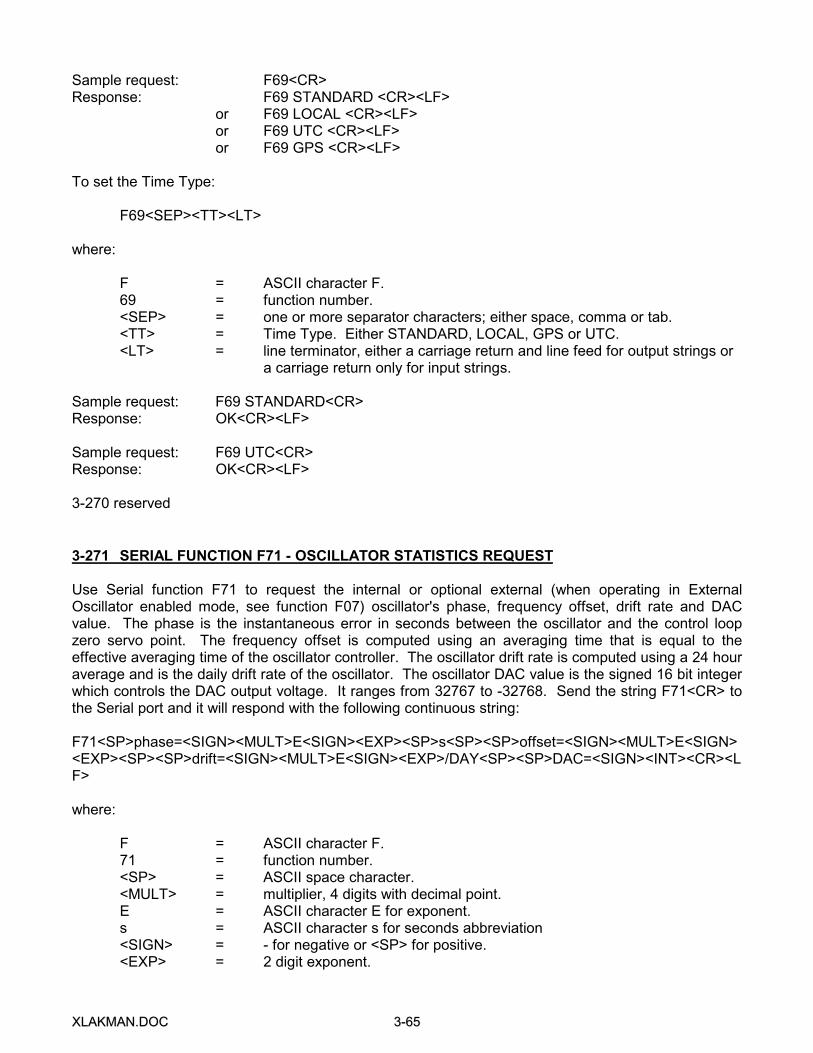
XXLLAAKKMMAANN..DDOOCC 33--6655
Sample request: F69<CR>Response: F69 STANDARD <CR><LF>
or F69 LOCAL <CR><LF>or F69 UTC <CR><LF>or F69 GPS <CR><LF>
To set the Time Type:
F69<SEP><TT><LT>
where:
F = ASCII character F.69 = function number.<SEP> = one or more separator characters; either space, comma or tab.<TT> = Time Type. Either STANDARD, LOCAL, GPS or UTC.<LT> = line terminator, either a carriage return and line feed for output strings or
a carriage return only for input strings.
Sample request: F69 STANDARD<CR>Response: OK<CR><LF>
Sample request: F69 UTC<CR>Response: OK<CR><LF>
3-270 reserved
3-271 SERIAL FUNCTION F71 - OSCILLATOR STATISTICS REQUEST
Use Serial function F71 to request the internal or optional external (when operating in ExternalOscillator enabled mode, see function F07) oscillator's phase, frequency offset, drift rate and DACvalue. The phase is the instantaneous error in seconds between the oscillator and the control loopzero servo point. The frequency offset is computed using an averaging time that is equal to theeffective averaging time of the oscillator controller. The oscillator drift rate is computed using a 24 houraverage and is the daily drift rate of the oscillator. The oscillator DAC value is the signed 16 bit integerwhich controls the DAC output voltage. It ranges from 32767 to -32768. Send the string F71<CR> tothe Serial port and it will respond with the following continuous string:
F71<SP>phase=<SIGN><MULT>E<SIGN><EXP><SP>s<SP><SP>offset=<SIGN><MULT>E<SIGN><EXP><SP><SP>drift=<SIGN><MULT>E<SIGN><EXP>/DAY<SP><SP>DAC=<SIGN><INT><CR><LF>
where:
F = ASCII character F.71 = function number.<SP> = ASCII space character.<MULT> = multiplier, 4 digits with decimal point.E = ASCII character E for exponent.s = ASCII character s for seconds abbreviation<SIGN> = - for negative or <SP> for positive.<EXP> = 2 digit exponent.
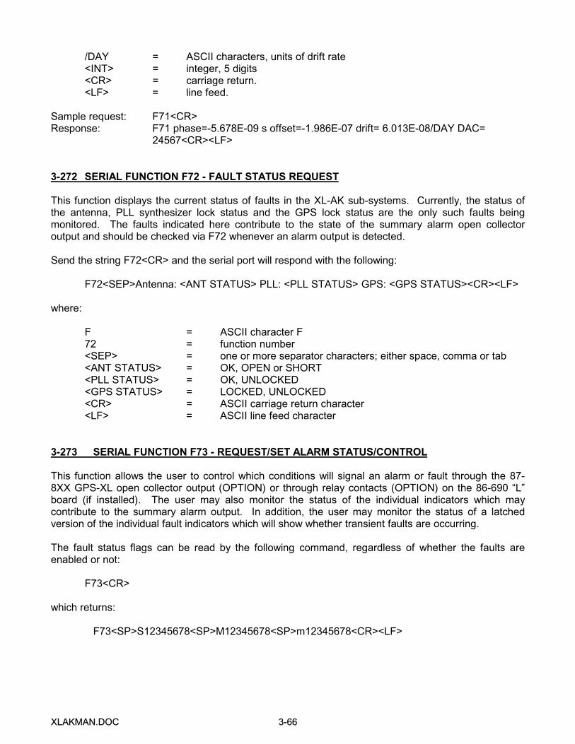
XXLLAAKKMMAANN..DDOOCC 33--6666
/DAY = ASCII characters, units of drift rate<INT> = integer, 5 digits<CR> = carriage return.<LF> = line feed.
Sample request: F71<CR>Response: F71 phase=-5.678E-09 s offset=-1.986E-07 drift= 6.013E-08/DAY DAC=
24567<CR><LF>
3-272 SERIAL FUNCTION F72 - FAULT STATUS REQUEST
This function displays the current status of faults in the XL-AK sub-systems. Currently, the status ofthe antenna, PLL synthesizer lock status and the GPS lock status are the only such faults beingmonitored. The faults indicated here contribute to the state of the summary alarm open collectoroutput and should be checked via F72 whenever an alarm output is detected.
Send the string F72<CR> and the serial port will respond with the following:
F72<SEP>Antenna: <ANT STATUS> PLL: <PLL STATUS> GPS: <GPS STATUS><CR><LF>
where:
F = ASCII character F72 = function number<SEP> = one or more separator characters; either space, comma or tab<ANT STATUS> = OK, OPEN or SHORT<PLL STATUS> = OK, UNLOCKED<GPS STATUS> = LOCKED, UNLOCKED<CR> = ASCII carriage return character<LF> = ASCII line feed character
3-273 SERIAL FUNCTION F73 - REQUEST/SET ALARM STATUS/CONTROL
This function allows the user to control which conditions will signal an alarm or fault through the 87-8XX GPS-XL open collector output (OPTION) or through relay contacts (OPTION) on the 86-690 “L”board (if installed). The user may also monitor the status of the individual indicators which maycontribute to the summary alarm output. In addition, the user may monitor the status of a latchedversion of the individual fault indicators which will show whether transient faults are occurring.
The fault status flags can be read by the following command, regardless of whether the faults areenabled or not:
F73<CR>
which returns:
F73<SP>S12345678<SP>M12345678<SP>m12345678<CR><LF>
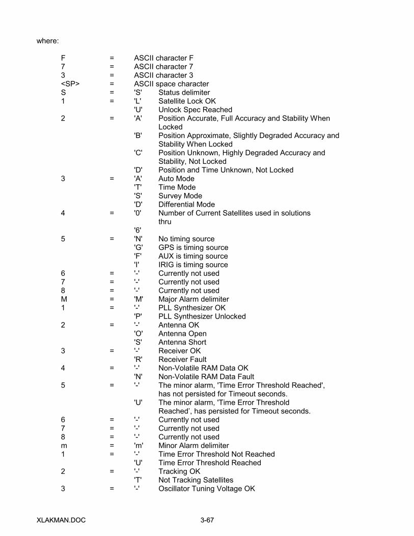
XXLLAAKKMMAANN..DDOOCC 33--6677
where:
F = ASCII character F7 = ASCII character 73 = ASCII character 3<SP> = ASCII space characterS = 'S' Status delimiter1 = 'L' Satellite Lock OK
'U' Unlock Spec Reached2 = 'A' Position Accurate, Full Accuracy and Stability When
Locked'B' Position Approximate, Slightly Degraded Accuracy and
Stability When Locked 'C' Position Unknown, Highly Degraded Accuracy and
Stability, Not Locked'D' Position and Time Unknown, Not Locked
3 = 'A' Auto Mode 'T' Time Mode 'S' Survey Mode 'D' Differential Mode
4 = '0' Number of Current Satellites used in solutionsthru
'6'5 = 'N' No timing source
'G' GPS is timing source'F' AUX is timing source'I' IRIG is timing source
6 = '-' Currently not used7 = '-' Currently not used8 = '-' Currently not usedM = 'M' Major Alarm delimiter1 = '-' PLL Synthesizer OK
'P' PLL Synthesizer Unlocked2 = '-' Antenna OK 'O' Antenna Open 'S' Antenna Short3 = '-' Receiver OK 'R' Receiver Fault4 = '-' Non-Volatile RAM Data OK 'N' Non-Volatile RAM Data Fault5 = '-' The minor alarm, 'Time Error Threshold Reached',
has not persisted for Timeout seconds.'U' The minor alarm, 'Time Error Threshold
Reached’, has persisted for Timeout seconds.6 = '-' Currently not used7 = '-' Currently not used8 = '-' Currently not usedm = 'm' Minor Alarm delimiter1 = '-' Time Error Threshold Not Reached 'U' Time Error Threshold Reached2 = '-' Tracking OK
'T' Not Tracking Satellites3 = '-' Oscillator Tuning Voltage OK
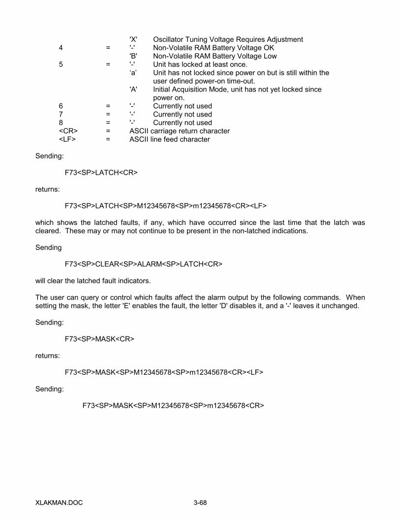
XXLLAAKKMMAANN..DDOOCC 33--6688
'X' Oscillator Tuning Voltage Requires Adjustment4 = '-' Non-Volatile RAM Battery Voltage OK 'B' Non-Volatile RAM Battery Voltage Low5 = '-' Unit has locked at least once.
‘a’ Unit has not locked since power on but is still within theuser defined power-on time-out.
'A' Initial Acquisition Mode, unit has not yet locked sincepower on.
6 = '-' Currently not used7 = '-' Currently not used8 = '-' Currently not used<CR> = ASCII carriage return character<LF> = ASCII line feed character
Sending:
F73<SP>LATCH<CR>
returns:
F73<SP>LATCH<SP>M12345678<SP>m12345678<CR><LF>
which shows the latched faults, if any, which have occurred since the last time that the latch wascleared. These may or may not continue to be present in the non-latched indications.
Sending
F73<SP>CLEAR<SP>ALARM<SP>LATCH<CR>
will clear the latched fault indicators.
The user can query or control which faults affect the alarm output by the following commands. Whensetting the mask, the letter 'E' enables the fault, the letter 'D' disables it, and a '-' leaves it unchanged.
Sending:
F73<SP>MASK<CR>
returns:
F73<SP>MASK<SP>M12345678<SP>m12345678<CR><LF>
Sending:
F73<SP>MASK<SP>M12345678<SP>m12345678<CR>

XXLLAAKKMMAANN..DDOOCC 33--6699
sets the alarm mask where the mask characters are:
M = 'M' Major Alarm delimiter1 = 'E' PLL Synthesizer Alarm Enabled
'D' PLL Synthesizer Alarm Disabled2 = 'E' Antenna Alarm Enabled
'D' Antenna Alarm Disabled3 = 'E' Receiver Alarm Enabled
'D' Receiver Alarm Disabled4 = 'E' Non-Volatile RAM Data Alarm Enabled
'D' Non-Volatile RAM Data Alarm Disabled5 = 'E' The minor alarm, 'Time Error Threshold Reached', has
persisted for Timeout seconds, Alarm Enabled'D' The minor alarm, 'Time Error Threshold Reached', has
persisted for Timeout seconds, Alarm Disabled6 = '-' Currently not used7 = '-' Currently not used8 = '-' Currently not usedm = 'm' Minor Alarm delimiter1 = 'E' Time Error Threshold Reached Alarm Enabled
'D' Time Error Threshold Reached Alarm Disabled2 = 'E' Tracking Alarm Enabled
'D' Tracking Alarm Disabled3 = 'E' Oscillator Tuning Voltage Alarm Enabled
'D' Oscillator Tuning Voltage Alarm Disabled4 = 'E' Non-Volatile RAM Battery Voltage Alarm Enabled
'D' Non-Volatile RAM Battery Voltage Disabled5 = 'E' Initial Acquisition Mode Alarm Enabled
'D' Initial Acquisition Mode Alarm Disabled6 = '-' Currently not used7 = '-' Currently not used8 = '-' Currently not used
The command returns:
OK<CR><LF>
if successful.
The time error threshold at which the time error fault is activated can be queried or set by the followingcommand.
Sending:
F73<SP>THRESHOLD<CR>
returns:
F73<SP>THRESHOLD<SP><nanoseconds><SP>ns<CR><LF>
where <nanoseconds> is the time error threshold in nsec.
Sending:

XXLLAAKKMMAANN..DDOOCC 33--7700
F73<SP>THRESHOLD<SP><nanoseconds><CR>
sets the time error threshold and returns:
OK<CR><LF>
if successful.
The timeout after which a time error fault becomes a timeout fault can be queried or set by thefollowing command.
F73<SP>TIMEOUT<CR>
which returns:
F73<SP>TIMEOUT<SP><seconds><SP>s<CR><LF>
where <seconds> is the timeout in seconds, between 0 and 86400.
Sending:
F73<SP>TIMEOUT<SP><seconds><CR>
sets the timeout and returns:
OK<CR><LF>
if successful.
If a checksum error is detected while recalling settings from non-volatile RAM, an NVRAM data fault isindicated. This same fault is active if an attempt was made to recall non-volatile RAM settings anddefault settings were created since no settings were found. This can occur if the non-volatile RAMbattery is low or jumper JP1 is removed. An NVRAM fault is indicated since the operator should checkthe non-volatile settings to verify that they are correct. After the operator has confirmed that allsettings are correct, the following command can be used to cancel the error, so that future errors canbe caught.
F73<SP>CLEAR<SP>NVRAM<SP>FAULT<CR>
clears the fault and returns:
OK<CR><LF>
XL-AK’s have a front panel Red/Green Status LED that is controlled by function 73. In general, faultsonly affect the Status LED if they are enabled. However, even if there is no enabled major or minorfault, the presence of the time error fault is indicated by a solid Green Status LED if BLINK = ENABLE(default). Normal operation within the user-defined time error threshold is indicated by the Green LEDblinking at a one pulse per second rate.
XXLLAAKKMMAANN..DDOOCC 33--7711
The Red/Green Status LED has the following states (when BLINK = ENABLE):
Off Power offSolid Red Major enabled alarm faultSolid Orange Minor enabled alarm fault, time error outside threshold.Blinking Red/Orange Minor enabled alarm fault, time error within threshold.Solid Green No enabled alarm faults, time error outside threshold.Blinking Green No enabled alarm faults, time error within threshold.
The Red/Green Status LED has the following states (when BLINK = DISABLE):
Off Power offSolid Red Major enabled alarm faultSolid Orange Minor enabled alarm faultSolid Green No enabled alarm faults
In all implementations using the 87-8XX GPS-XL Module, the open collector alarm output has thefollowing states:
Off (High Z) Power offOff (High Z) Error, major or minor enabled alarm fault.On (Low Z) Normal, no major or minor enabled alarm faults.
If the processor on the 87-8XX GPS-XL Module were to fail, resulting in a failure to trigger thewatchdog timer, the watchdog timer would reset the processor and attempt to restart the system.During the processor reset, the Status LED output would be Red, and the alarm output transistor opencollector would be off, indicating a fault. If the processor were unable to recover and resume triggeringthe watchdog timer, a succession of watchdog timer timeouts followed by resets would result,producing a blinking Red Status LED. At the same time, the open collector alarm output transistormight either be off, or might toggle between off and on following the repeated resets, indicating analarm condition.
LED BLINKING can be ENABLED or DISABLED in all but the processor reset condition.
Sending:
F73<SP>BLINK ENABLE<CR>
enables the LED to blink under the conditions given above. The response is:
OK<CR><LF>
if successful.
Sending:
F73<SP>BLINK DISABLE<CR>
disables the LED from blinking in all but the processor reset mode as given above.
Minor Alarm conditions may be delayed if power-on Minor Alarm SUPPRESS is set to a value (inseconds). The Minor Alarms will be suppressed until either the unit power-on time exceeds the MinorAlarm suppress time or the unit locks to GPS.
XXLLAAKKMMAANN..DDOOCC 33--7722
The power-on Minor Alarm suppress time can be read by the following command:
F73<SP>SUPPRESS<CR>
which returns:
F73<SP>POWER-ON<SP>MINOR<SP>ALARM<SP>SUPPRESS<SP><seconds><SP>s<CR><LF>
where:
F = ASCII character F.73 = function number.<seconds> = seconds from 0 to 86400.<SP> = ASCII space character.<CR> = Carriage Return.<LF> = Line Feed.
The Minor Alarm suppression power-on timeout can be set by the following command:
F73<SP>SUPPRESS<SP><seconds><CR>
The seconds can be set to any value from 0 to 86400 which sets the suppress time and returns:
OK<CR><LF>
if successful.
3-274 through 3-278 reserved
3-279 SERIAL FUNCTION F79 - WARM START
This function issues a reset command to the Trimble SVeeSix GPS core module. It does not clearstored almanac and ephemeris data which are retained in battery-backed RAM.
Send the string F79<CR> and the serial port will respond by initiating a warm start.
Sample entry: F79<CR>Response: OK<CR><LF>
XXLLAAKKMMAANN..DDOOCC 55--11
SECTION V
86-690 OUTPUT CONFIGURATION “L” BOARD
5-1 86-690 “L” BOARD INTRODUCTION
The 86-690 Output Configuration Board “L” Board may or may not be installed in your unit -- refer tothe Installed Options Checklist in the front of the manual. This board allows the user to select one ofseveral analog or digital signals that will appear at five rear panel BNCs labeled J1 through J5. Signalselection is made by the installation of jumpers. Each BNC output has an associated header strip onthe option board. Each header strip requires two, 2-pin jumpers. One jumper defines the signal formatand the second jumper selects the appropriate analog or digital driver. See installation instructions fordetailed information.
5-2 SIGNAL SPECIFICATIONS
Analog Output Drive:
Amplitude: 1 V rms into 50 ohmsConnector: Female BNC
Analog Output Format Description - the following output formats are available:
IRIG B AM IRIG B amplitude modulatedOPT IRIG H AM IRIG H amplitude modulated (optional)OPT IRIG E AM IRIG E amplitude modulated (optional)
Digital Output Drive:
Amplitude: +2.5 Vdc into 50 ohms (+/-24 ma), (0 to +5 Vdc Open Circuit)Connector: Female, BNC
Alarm Relay Specifications (OPTION)
Contacts: 1 Form CMax Voltage: 48 VAC/VdcMax Current: 2A @ 24 Vdc
Digital Output Format Description:
IRIG B 001, IRIG H 001, and IRIG E 001 - These are the DC Shift formats of IRIG B, H, and Etime code.
ALARM - This output level is asserted by various programmable alarm conditions such astiming error during loss of lock or antenna shorts. Programming is described in the manualsection titled: KEYPAD FUNCTION F73 - DISPLAY/SET ALARM STATUS/CONTROL andSERIAL FUNCTION F73 - REQUEST/SET ALARM STATUS/CONTROL.
PROGPULSE - The Programmable Pulse Output allows the generation of a preciselysynchronized trigger pulse at an arbitrary time and with arbitrary pusewidth in integer multiplesof 1 ms. The rising edge of the trigger output may be programmed to occur with 1 ms

XXLLAAKKMMAANN..DDOOCC 55--22
resolution and will be within 150 ns of the UTC millisecond. Programming is done via the serialport. Refer to “SERIAL FUNCTION F26 - PROGRAMMABLE PULSE OUTPUT” (in Section III)for details of the programming of this output pulse.
PUSLE RATES - 1 PPS, 1 KPPS, 10 KPPS, 1 MPPS, 10 MPPS - These pulse rate outputshave a 50 percent duty cycle with their rising edge “on-time.”
SPCL 1 THROUGH SPCL 4 - The Special Output signals are digital outputs reserved forspecial timing applications.
5-3 SIGNAL CONFIGURATION
Signal configuration requires the removal of the top cover to gain access to selection jumpers. Theonly equipment required for installation is a Phillips screwdriver.
CAUTION: Remove the AC Power connector before removing the top cover. This instrumentcontains high voltage which can cause electric shock that could result in severe injury or evendeath.
Remove the screws located on the sides of the chassis. Remove the top cover. Locate the jumperheader rows which are shown in Figure 1. There are five 20-pin header rows identified as CONFIG J1through CONFIG J5. These correspond to BNCs J1 through J5 on the rear panel. Two headerjumpers are required for each output. One jumper selects the signal format such as IRIG B or 1PPSand a second jumper selects the appropriate output driver such as analog (ANALDRV) or digital(DIGDRVR). Only the amplitude modulated outputs (IRIG B AM, optional IRIG H AM and IRIG E AM)require the analog driver. All other outputs require the digital driver.

XXLLAAKKMMAANN..DDOOCC 55--33
FIGURE 1 CONFIGURATION HEADER
J1 J2 J3 J4 J5CONFIG CONFIG CONFIG CONFIG CONFIG
IRIG B AM • • • • • • • • • •OPT IRIG H AM • • • • • • • • • •OPT IRIG E AM • • • • • • • • • •IRIG B 001 • • • • • • • • • •IRIG H 001 • • • • • • • • • •IRIG E 001 • • • • • • • • • •ALARM • • • • • • • • • •PROGPULSE • • • • • • • • • •1PPS • • • • • • • • • •1KPPS • • • • • • • • • •10KPPS • • • • • • • • • •100KPPS • • • • • • • • • •1MPPS • • • • • • • • • •10MPPS • • • • • • • • • •SPCL 1 • • • • • • • • • •SPCL 2 • • • • • • • • • •SPCL 3 • • • • • • • • • •SPCL 4 • • • • • • • • • •ANALDRV • • • • • • • • • •DIGDRVR • • • • • • • • • •
Optional IRIG E & H AM Output Code Adjustments - The optional outputs should normally not requireadjustment. They are adjusted at the factory for a signal level of 1 volt rms into a 50 ohm load. Theoutputs are adjusted for a mark to space ratio of 3 to 1.
R10 - IRIG H amplitudeR11 - IRIG E amplitudeR13 - IRIG E ratioR14 - IRIG H ratioR17 - IRIG H and IRIG E phase (adjust for minimum discontinuity
between high and low amplitude carrier signals)
5-4 GENERAL OPERATION
Once the jumper installation is complete, the outputs are automatically enabled upon power-up andoutput continuously. If an output should not appear to operate properly be sure that the jumperselection for the driver output type (ANALDRV or DIGDRVR) is correct for the signal format selected.Also, some outputs such as the Programmable Pulse and the Alarm output require program setup tobe enabled.
XXLLAAKKMMAANN..DDOOCC 55--44
5-5 THEORY OF OPERATION
Reference schematic 86-690, sheet 2. This circuitry shows the header strip jumpers and the analogand digital drive logic for BNC outputs J1 through J4. U15 and U17 are dual analog drivers. U18 is anoctal digital driver.
Reference schematic 86-690, sheet 3. This drawing shows the jumper header strip, analog, and digitaldriver for BNC J5. U19 is the analog driver and U18 is the digital driver. Timing outputs are writteneach millisecond to latch U3. These outputs are switched out on the next 1 KPPS clock from U4. Thisoutput latch provides the signals IRIG E DC Shift, IRIG H DC Shift, Programmable Pulse and SpecialOutputs 1 through 4. The programmable logic device at U11 provides address decode logic to allowthe GPS-XL to write to the front panel display and read keyboard input. It also outputs a strobe signalto retrigger one-shot U14. The strobe is turned off when an “ALARM” condition is asserted. Thisoutput is routed to the header strips and also drives the optional alarm relay, K1.
Reference schematic 86-690, sheet 4. This drawing shows the keyboard bus driver logic U1, and thekeyboard decoder chip U2. Potentiometer R1 adjusts the viewing angle control voltage for the frontpanel LCD display.
Reference schematic 86-690, sheet 5. This drawing shows counter logic, which is used to divide the1 MPPS clock down to 100 KPPS and 10 KPPS outputs. These clock outputs are synchronized to the1 KPPS close by dual flip-flop U5. The 1 KPPS clock drives the 1 KHz filter shown by componentsU12 and their surrounding capacitors and resistors. The output at U12 pin 7 is a 1 KHz sine wave.This signal is modulated to produce IRIG E AM and IRIG H AM. Modulation is achieved by using theDC Shift format of the codes to select an attenuated or non-attenuated level of the sine wave signal.Potentiometers R13 and R14 are used to control the ratio of IRIG E and IRIG H, respectively. U9 is ananalog switch that is driven by the DC code format. Potentiometers R11 and R10 control the amplitudeof each of the above formats.
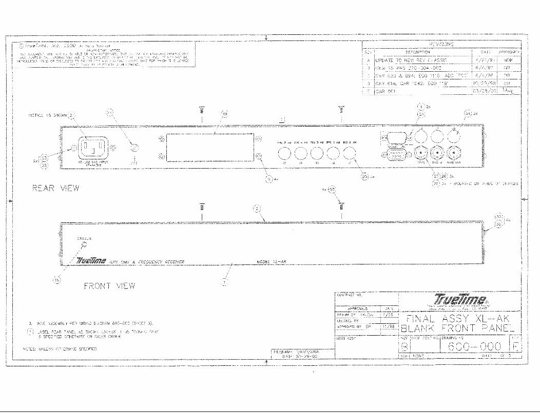

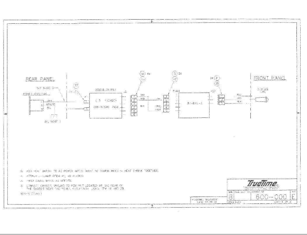
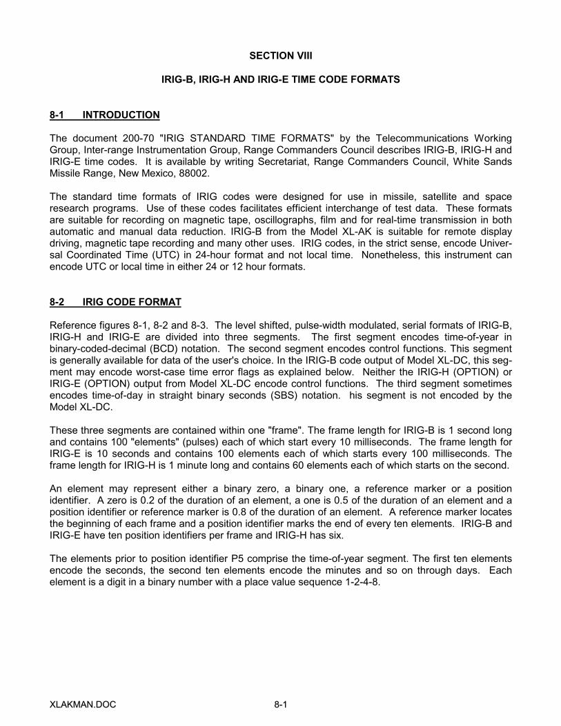
XXLLAAKKMMAANN..DDOOCC 88--11
SECTION VIII
IRIG-B, IRIG-H AND IRIG-E TIME CODE FORMATS
8-1 INTRODUCTION
The document 200-70 "IRIG STANDARD TIME FORMATS" by the Telecommunications WorkingGroup, Inter-range Instrumentation Group, Range Commanders Council describes IRIG-B, IRIG-H andIRIG-E time codes. It is available by writing Secretariat, Range Commanders Council, White SandsMissile Range, New Mexico, 88002.
The standard time formats of IRIG codes were designed for use in missile, satellite and spaceresearch programs. Use of these codes facilitates efficient interchange of test data. These formatsare suitable for recording on magnetic tape, oscillographs, film and for real-time transmission in bothautomatic and manual data reduction. IRIG-B from the Model XL-AK is suitable for remote displaydriving, magnetic tape recording and many other uses. IRIG codes, in the strict sense, encode Univer-sal Coordinated Time (UTC) in 24-hour format and not local time. Nonetheless, this instrument canencode UTC or local time in either 24 or 12 hour formats.
8-2 IRIG CODE FORMAT
Reference figures 8-1, 8-2 and 8-3. The level shifted, pulse-width modulated, serial formats of IRIG-B,IRIG-H and IRIG-E are divided into three segments. The first segment encodes time-of-year inbinary-coded-decimal (BCD) notation. The second segment encodes control functions. This segmentis generally available for data of the user's choice. In the IRIG-B code output of Model XL-DC, this seg-ment may encode worst-case time error flags as explained below. Neither the IRIG-H (OPTION) orIRIG-E (OPTION) output from Model XL-DC encode control functions. The third segment sometimesencodes time-of-day in straight binary seconds (SBS) notation. his segment is not encoded by theModel XL-DC.
These three segments are contained within one "frame". The frame length for IRIG-B is 1 second longand contains 100 "elements" (pulses) each of which start every 10 milliseconds. The frame length forIRIG-E is 10 seconds and contains 100 elements each of which starts every 100 milliseconds. Theframe length for IRIG-H is 1 minute long and contains 60 elements each of which starts on the second.
An element may represent either a binary zero, a binary one, a reference marker or a positionidentifier. A zero is 0.2 of the duration of an element, a one is 0.5 of the duration of an element and aposition identifier or reference marker is 0.8 of the duration of an element. A reference marker locatesthe beginning of each frame and a position identifier marks the end of every ten elements. IRIG-B andIRIG-E have ten position identifiers per frame and IRIG-H has six.
The elements prior to position identifier P5 comprise the time-of-year segment. The first ten elementsencode the seconds, the second ten elements encode the minutes and so on through days. Eachelement is a digit in a binary number with a place value sequence 1-2-4-8.
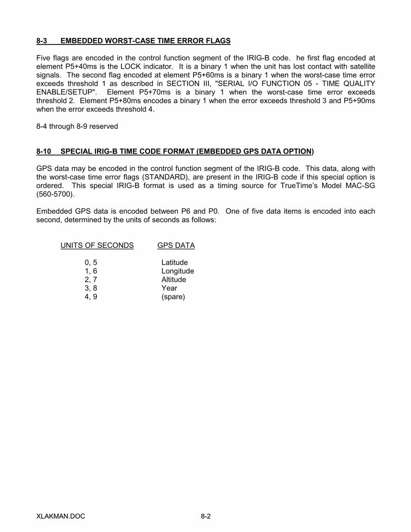
XXLLAAKKMMAANN..DDOOCC 88--22
8-3 EMBEDDED WORST-CASE TIME ERROR FLAGS
Five flags are encoded in the control function segment of the IRIG-B code. he first flag encoded atelement P5+40ms is the LOCK indicator. It is a binary 1 when the unit has lost contact with satellitesignals. The second flag encoded at element P5+60ms is a binary 1 when the worst-case time errorexceeds threshold 1 as described in SECTION III, "SERIAL I/O FUNCTION 05 - TIME QUALITYENABLE/SETUP". Element P5+70ms is a binary 1 when the worst-case time error exceedsthreshold 2. Element P5+80ms encodes a binary 1 when the error exceeds threshold 3 and P5+90mswhen the error exceeds threshold 4.
8-4 through 8-9 reserved
8-10 SPECIAL IRIG-B TIME CODE FORMAT (EMBEDDED GPS DATA OPTION)
GPS data may be encoded in the control function segment of the IRIG-B code. This data, along withthe worst-case time error flags (STANDARD), are present in the IRIG-B code if this special option isordered. This special IRIG-B format is used as a timing source for TrueTime’s Model MAC-SG(560-5700).
Embedded GPS data is encoded between P6 and P0. One of five data items is encoded into eachsecond, determined by the units of seconds as follows:
UNITS OF SECONDS GPS DATA
0, 5 Latitude1, 6 Longitude2, 7 Altitude3, 8 Year4, 9 (spare)

XXLLAAKKMMAANN..DDOOCC 88--33
Figure 8-1 IRIG-B Time Code
10 20 30 40 50 60 70 80 90 00
P5 PR
REF
IRIG-B TIME CODE FORMAT
TIME FRAME 1 SECOND
BINARY 1 (TYPICAL)
10ms (TYPICAL)
TIME
TIME IN 0.01 SECONDS
TYPICAL MODULATED CARRIER (1000Hz)
3XX
IDENTIFIER. DURATION
HOURS
BCD TIME-OF-YEAR
P0 PR P1 P2
0.01 SECOND INDEX
2 MILLISECONDS
MARKER. DURATION
0.1 SECOND POSITION
8 MILLISECONDS
1 2 4 8 110 20 40 2 4 8 10 20 40 1 2 4 8
REF SECONDS
ON TIME
MINUTES
P3 P4
2010 20 1 2 4 8 10 40 80100 200
5ms
DAYS
WEIGHTED CONTROL
DIGITS 5ms TYPICAL
CONTROL FUNCTIONS
P6 P7
TIME QUALITY 4
TIME QUALITY 3
TIME QUALITY 2
TIME QUALITY 1
LOCK INDICATOR
P8 P9 P0
10 20 30 40 50 60 70 80 90 00
P5 PR
REF
IRIG-E TIME CODE FORMAT
BINARY 1 (TYPICAL)
100ms TYPICAL
TIME FRAME 10 SECONDS
TIME IN 0.1 SECONDS
TIME
TIME IN 0.1 SECONDS
MARKER. DURATION
20 MILLISECONDS
HOURS
BCD TIME-OF-YEAR
IDENTIFIER. DURATION
TYP 1-SECOND POSITION
0.01 SECOND INDEX
P0 PR P1
110 20 40
80 MILLISECONDS
2 4 8 10 20 40
P2
1 2 4 8
REF SECONDS
ON TIME
MINUTES
20
P3
10 20 1 2 4 8 10
50ms
P4
40 80100 200
DAYS
WEIGHTED CONTROL DIGITS
DURATION 50 MILLISECONDS
CONTROL FUNCTIONS
P6 P7 P8 P9 P0
Figure 8-2 IRIG-E Time Code

XXLLAAKKMMAANN..DDOOCC 88--44
Figure 8-3 IRIG-H Time Code
PRP0
REF
P1 P2 P3 P4 P5 P0 PR
REF
0 10 20 30 40 50 0
TIME FRAME 1 MINUTE
TIME
ON TIME TIME IN SECONDS
BCD TIME-OF-YEAR
MINUTES HOURS DAYS CONTROL FUNCTIONS
1 2 4 8 10 20 40 1 2 4 8 10 20 1 2 4 8 10 20 40 80 100 200
0.5 SEC
BINARY 1 (TYPICAL)
TYPICAL 1-SECOND INDEC MARKER
DURATION 0.2 SECONDS
TYPICAL 10-SECOND POSITION IDENTIFIER
DURATION 0.8 SECONDS
1-SEC
TYPICAL
WEIGHTED CONTROL DIGIT
0.5 SEC TYPICAL
IRIG-H TIME CODE FORMAT