manual - · pdf fileas rotor the dcg-56 evrp employs a steel rotor without any kind of...
TRANSCRIPT

Transmotor generator
DCG-56 EVRP
MANUAL
Transmotor ApS. Lemtorpvej 13-17, DK-7620 Lemvig Tel. 45 9664 0977 Fax. 45 9664 0982 e-mail: [email protected] www.transmotor.com

- 2 - 2
1 Product description. 1.1 Transmotor charging generators Transmotor fabricates a whole range of generators for battery charging. Our products are especially designed for on the sea use, in the marine sector, in fishing vessels, on small tugboats etc. Our generators should primarily be used were demands for reliability and quality are high. The unique brush less design gives a robust and nearly maintenance free generator. Another advantage of the design is that charging starts at low RPM. The dis-advantages compared to other types of generators are bigger size and weight. With the DCG-56 EVRP we improve the low end of our range of generators by bringing the ACG charging characteristic from our ACG/AVRR generators to the DCG-55 size housing. It makes a higher charging current possible at all RPM. Boats and fishing vessels with a DCG-55 installed, gains the higher charging current simply by replacing the DCG-55 with a DCG-56 unit.
1.2 The brush less alternator design. As rotor the DCG-56 EVRP employs a steel rotor without any kind of windings. This is what makes the generator almost maintenance free. An excitation coil is placed at the middle of the frame in between two 3-phase stators wound in reverse to each other, one working in the rotors magnetic north pole and the other in the magnetic south pole. The excitation coil magnetizes the rotor given it its north and south pole. When the rotor ro-tates, its 8 teeth’s will induce AC voltage in the stators. The outputs from the two stators are connected in parallel given a 3-phase AC voltage. This voltage is rectified in a built in rectifier to obtain the DC output voltage. The generator is self-exciting. The excitation voltage comes from a built in regulator unit. This unit contains its own rectifier and provides the excitation voltage directly from the stators AC voltage. The regulator measures the DC output voltage and regulates the volt-age to the excitation coil, so a constant output voltage is maintained. The regulator unit also provide full electronic controlled, -current limitation, -over voltage protection and protection against over heating. The regulator is build onto the lid to the terminal box, using the lid as cooling surface; it is fully embedded in two-part polyurethane compound. All connections between excitation coil, stators, rectifier and regulator unit are made on the terminal board, inside the terminal box on the generator top. Output is taking on two heavy -duty terminals.

- 3 - 3
Wiring diagram for DCG-56 EVRP Part no. 26027001
- 4 - 4
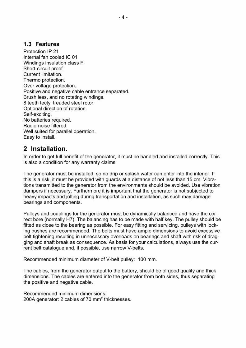
1.3 Features Protection IP 21 Internal fan cooled IC 01 Windings insulation class F. Short-circuit proof. Current limitation. Thermo protection. Over voltage protection. Positive and negative cable entrance separated. Brush less, and no rotating windings. 8 teeth tectyl treaded steel rotor. Optional direction of rotation. Self-exciting. No batteries required. Radio-noise filtered. Well suited for parallel operation. Easy to install.
2 Installation. In order to get full benefit of the generator, it must be handled and installed correctly. This is also a condition for any warranty claims. The generator must be installed, so no drip or splash water can enter into the interior. If this is a risk, it must be provided with guards at a distance of not less than 15 cm. Vibra-tions transmitted to the generator from the environments should be avoided. Use vibration dampers if necessary. Furthermore it is important that the generator is not subjected to heavy impacts and jolting during transportation and installation, as such may damage bearings and components. Pulleys and couplings for the generator must be dynamically balanced and have the cor-rect bore (normally H7). The balancing has to be made with half key. The pulley should be fitted as close to the bearing as possible. For easy fitting and servicing, pulleys with lock-ing bushes are recommended. The belts must have ample dimensions to avoid excessive belt tightening resulting in unnecessary overloads on bearings and shaft with risk of drag-ging and shaft break as consequence. As basis for your calculations, always use the cur-rent belt catalogue and, if possible, use narrow V-belts. Recommended minimum diameter of V-belt pulley: 100 mm. The cables, from the generator output to the battery, should be of good quality and thick dimensions. The cables are entered into the generator from both sides, thus separating the positive and negative cable. Recommended minimum dimensions: 200A generator: 2 cables of 70 mm² thicknesses.

- 5 - 5
This is in accord with Lloyd’s specification at 45° C ambient temperature, and 80° C as the max. Allowed cable temperature. To ensure a good connection, secure tightening off the connections at both cable ends must be made. Two DCG-56 generators will normally share the power equally during parallel operation, if they are adjusted to the same output voltage, and reasonably loaded. The DCG-56 can operate in parallel with all other types of Transmotor charging generators.
3 Connecting auxiliaries A wide range off auxiliaries can be connected to the generator; the free terminals at the control print are for connection of these auxiliaries. The terminal box has a hole for mounting a small PG-11 cable gland. Use this as entrance for the cable to the auxiliaries.

- 6 - 6
3.1.1 Making use of the control voltage. When the generator is operating, a control voltage is present between regulator terminal 9 and 14. This voltage corresponds to the charging voltage, and can be used for indicating whether the generator is operating or not. Maximum permissible load is 1A. An external fuse is optional, as the regulator fuse will protect against short-circuit.
3.1.2 Using remote battery voltage sensing. The regulator has input terminals for remote voltage sensing. To apply, connect a wire from regulator terminal 6 to the positive battery terminal, and another from regulator ter-minal 2 to the negative battery terminal. These connections must be provided with 100 mA fusing. The regulator will now regulate so a constant voltage is present at the battery ter-minals rather than on the generator output terminal, thus eliminating voltage drop on the cables to the batteries. This is not intended as a substitute for using good thick cables. If a cable break happens, or a main fuse to the battery breaks when using remote sensing, the fuse on the regulator can break due to sudden over voltage on the generator output terminals.
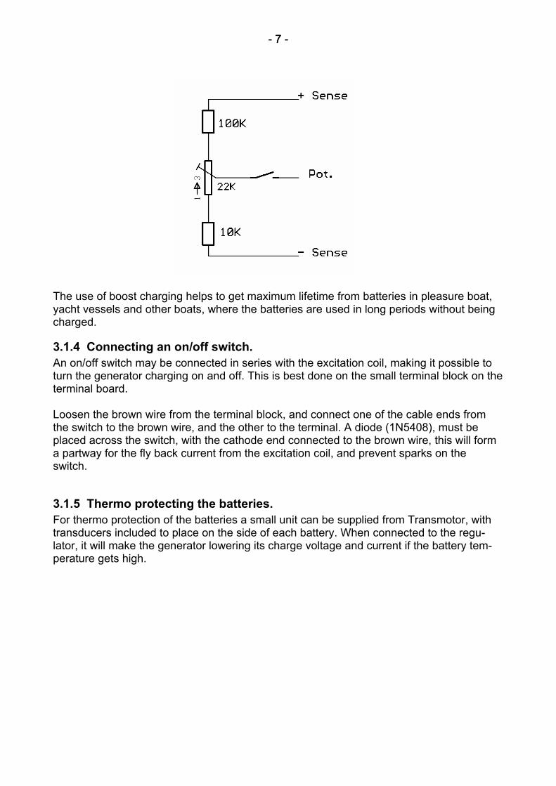
3.1.3 Using remote voltage adjustment (Boost charging) An external potentiometer can be connected to the regulator, so it is possible to raise the charging voltage manually. If the batteries are discharged, it sometimes can be good for the batteries to be charged with a higher voltage for a few hours. Consult the specifications of the batteries to see how high a charging voltage they may be charged with. Also make sure that there is no electronic equipment connected that can be damaged at the higher voltage. The following diagram shows how to connect a potentiometer, so the voltage can be ad-justed from –1% to +10%, of the regulator setting. It includes an on/off switch, so the re-mote function can be turned on and off. Instead of a switch, a timer-relay can be mounted, so boost charging can be turned off automatically.
- 7 - 7
The use of boost charging helps to get maximum lifetime from batteries in pleasure boat, yacht vessels and other boats, where the batteries are used in long periods without being charged.
3.1.4 Connecting an on/off switch. An on/off switch may be connected in series with the excitation coil, making it possible to turn the generator charging on and off. This is best done on the small terminal block on the terminal board. Loosen the brown wire from the terminal block, and connect one of the cable ends from the switch to the brown wire, and the other to the terminal. A diode (1N5408), must be placed across the switch, with the cathode end connected to the brown wire, this will form a partway for the fly back current from the excitation coil, and prevent sparks on the switch.
3.1.5 Thermo protecting the batteries. For thermo protection of the batteries a small unit can be supplied from Transmotor, with transducers included to place on the side of each battery. When connected to the regu-lator, it will make the generator lowering its charge voltage and current if the battery tem-perature gets high.

- 8 - 8
4 Operation. When the rotor reaches the generators minimum R.P.M. The self-exciting circuits will start the generator up, raising the stators output voltage until the generator reaches its DC out-put voltage setting. At start up, the regulators rectified AC from the stators are fully suppli-ed to the excitation coil. When the generator output voltage has risen to the setting, regu-lation begins, keeping a constant output voltage. The regulator uses pulse width regulation on the excitation coil; changing the voltage direction on the coil, charging and discharging the rotors magnetic field. When the output current attempts to exceed the generators maximal allowed current, the regulators internal current limiting circuit will set-in to protect the generator, by lowering the output voltage, thus keeping the current at its max. The regulator measures the current by using the voltage drop on the negative cable outlet from the rectifier unit as a shunt voltage. Terminal 3 on the regulator is connected directly to one of the diodes in the rectifier unit. Terminal 1 is connected to the negative output ter-minal. The regulator uses the small voltage drop between terminal 1 and 3 for its current limiter. As the cable lengths may differ slightly from one rectifier unit to another, the current limiter is adjusted individually on each generator. Please check the current limiter setting after having replaced the rectifier- or regulator unit. If the stator temperature increases to near the maximum allowed temperature, the temperature protection circuit may set-in lowering the output voltage to protect the stators from overheating. Both stators have a temperature dependent resistor fixed to its windings, used by the regulator for temperature protection. The two resistors are connected in series, with one end, of the series connection, connected to the negative output terminal, and the other to terminal 5 on the regulator. When the generator is working in high tem-perature surroundings the temperature protecting circuit will insure, that it charges as much as possible without overheating. The regulator also has a circuit for over voltage protection built in. If the power transistors inside the regulator short circuits, so the regulation stops, and the output voltage rises above the max. output voltage, this circuit will blow the regulator fuse, to protect batteries and attached equipment.
5 Adjusting the regulator. The regulator is adjusted from factory, for the charging of Lead-Acid batteries. Normally the factory adjustments will be satisfactory and no adjustment needed.

- 9 - 9
5.1 Adjusting the output voltage. With the generator running at medium speed, and with a small load, output voltage can be adjusted on the potentiometer market “Volt”. A clockwise turn will raise the voltage. Tur-ning anticlockwise will lower the voltage. From factory the output voltage is adjusted to 27.5 VDC, which is the constant charging voltage recommended by most manufacturers of Lead-Acid batteries. It is important, that the generator is not very hot or heavy loaded when adjusting the output voltage, as the regulator in such cases can be lowering the voltage to protect the generator.
5.2 Adjusting the current limit. The current limit is factory set to the generators maximum allowed output current. In spe-cial cases, for instance when using existing cables of a smaller cable size than the recom-mended, the maximum output current can be lowered further. This is done by turning po-tentiometers market “Amp. F” and “Amp. C” anti clockwise, while running the generator at high speed. Fine adjustment is made on “Amp. F”, and coarse adjustment is made on “Amp. C”. In order to see the setting in function a high load must be attached to the gene-rator. When the generator load exceeds the setting, the regulator will lower the output vol-tage keeping the output current at the setting. Some kind of ampere meter must be attach-ed to measure this current. Notice, that as the generator gets heated up, it can lower the output voltage further to protect the stators from overheating. Also notice that as the rota-tion speed decreases the maximum generator effect will naturally decrease. The adjust-ment should be checked on a cold generator, running near its maximum speed. The adjustment of the current limiter requires qualified service personal.
5.3 Testing and adjusting the over voltage protection (OVP). The over voltage protection is set to 31.7 VDC. A quick function test can be done. The test is made by raising the output voltage using an external resistor and/or potentiometer. Batteries and voltage sensitive equipment must first be disconnected from the generator output. The test requires some spare fuses, for the regulator, at hand. If the generator output is adjusted to 27.5 VDC, the fuse should not blow when a 18 K. ohm resistor is connected to regulator terminal 2 and 4, This will raise the output voltage to approx. 30.5 VDC. But when connecting a 10 K. Ohm resistor to the two terminals, the regulator fuse should blow. Instead of using fixed resistors, a 10 K. Ohm potentiometer in series with a 10 K. Ohm resistor can be attached to terminal 2 and 4, so the voltage can be slowly raised until the fuse blows, and the setting fully checked. Adjusting the potentiometer marked ”OVP” changes the setting, turning clockwise will raise the voltage, and turning anti clockwise lowers the voltage.

- 10 - 10
6 Maintenance The maintenance on the generator is limited to cleaning and when necessary, bearing re-placement. Once a year the generator should be sent to an authorized service workshop for complete cleaning and inspection. To avoid undue overload on bearings and shaft end, all belts should be inspected regular-ly.
6.1 Belts inspection. Check if the belts are in good shape, i.e. no cracked belts, no frayed belt sides, no worn belts. If any belt is not in order, all parallel running belts should be replaced simultaneously in order to obtain the same degree of tightness. The belts must be tightened to a degree, so they do not slide, neither under normal operation, nor by initial run up, or acceleration. However keep and adequate operational safety margin, do not over tighten the belts. After belt replacement or when installing a new generator, belt tightening should be check-ed after a short period of operation.
6.2 Disassembling the generator. Pull off pulley or coupling. Remove bearing covers, with due care to the trust washer in the bearing house at rear. Remove the screws fixing the end shields to the frame, and remove the shields by means of a wooden or plastic-head hammer, eventually aided by two heavy-duty screwdrivers. Lift the rotor out of the stator housing from the fan end. If the bearings are not to be re-placed, they should be covered. Clean the machine, repair as required and make insulation test.
6.2.1 Assembling the generator. Assembling is done, following the above instructions in reverse order. Remember to place the bearing trust washer at the rectifier end.
6.3 Bearing replacement. Both bearings can readily be pulled off by means of an ordinary bearing puller. Clean shaft ends and, if needed the inside bearing cover. Remember to fit the inside cover prior to re-fitting the bearing. It is important that the new bearings are of right type, and fitted correctly with the proper tools. Check the spare part list for purchasing correct bearing types. Fit the bearings on the shaft, either after heating to approx. 80-100°C, or in the cold state by means of a ball bearing drift.
- 11 - 11
6.4 Insulation test. Insulation test are done, with a 500 VDC megger. Inside the regulator, there is a radio-interference suppression filter with connection to frame throw terminal 15. All connections from the regulator terminal 15 to frame must be disconnected, before megger testing. Isolation Test on the stators is done from frame to the three AC-terminals. The excitation coil and the thermo protecting PTC-resistors can be insulation tested as well, if they are disconnected from the regulator. The megger reading should show that the frame is totally insulated from all electrical wires.
7 Fault tracing.
7.1 The generator blows the regulator fuse. The fuse most likely blows, because of a regulation fault, causing an over voltage fault to occur. The regulator in this case is supplying the control voltage fully to the excitation coil, without regulation. The over voltage protection takes the fuse, whenever an over voltage fault occurs, to protect batteries and equipment attached to the generator. If auxiliaries are connected to the regulator, the fault can lay here. Disconnect all auxiliari-es, attached to regulator terminals 2, 4, 6 and 9. Replace the fuse and try to run the gene-rator without auxiliaries attached. Another reason, for the missing regulation, could be a missing connection to the regulator, so the regulator cannot feel the voltage on the output terminals. Run the generator without fuse. Measure the voltage at the output terminals, check, that the same voltage is present between regulator terminal 10 and 1, and between terminal 10 and 3. Follow the instruction for checking the excitation coil. If there are no bad connections, and the excitation coil is in order, the regulator is most likely broken, and should be replaced. Follow the instruction for checking the regulator.

- 12 - 12
7.2 The generator does not charge. Check if the regulator fuse is intact, if not follow the above faultfinding procedure. Check for mechanical faults. Is the belt transmission all right? Are there any visible or audible faults? Check that all cable connections are tight and unbroken. All the voltage measurements in the following are measured with the generator running slightly above minimum R.P.M., and with no load attached to the output terminals. While disconnecting wires, the generator should be stopped, and then started again when measuring the voltages.
7.2.1 Testing for stator fault. Check the voltage on the 3 AC terminals, it should be symmetrical and approx. 2 VAC. Try to magnetise the rotor if the voltage is symmetrical but to low.
7.2.2 Testing for main rectifier fault. Check the DC output, it should have a slightly higher DC reading than the AC voltage. Check that the same voltage is present between regulator terminals 10 and 3, and between 10 and 14.
7.2.3 Testing for regulator fault. Check that the control voltage between terminal 9 and 14 is approx. the same as the DC output. Measure the excitation voltage between terminal 8 and 7; it should be approx. 0.7 Volt lower. If the control voltage is not present between terminal 9 and 14, or the excitation voltage is not present, the regulator is most likely broken.
7.2.4 Magnetising the generator. If the voltage from the stators is to low for the generator to run up, it could be because the generator has lost some of its magnetism, so the remanence voltage is to low. Disconnect the wires from the excitation coil on the terminal board. Connect the wire that was attached to the brown wire (from the regulator terminal 8) to the positive terminal from the 24V bat-tery supply, and the other wire to the negative terminal for approx 1 second, this will mag-netise the generator.
7.2.5 Checking the excitation coil and thermo resistors The resistance of the excitation coil and thermo resistors can be measured with an ohm-meter. The excitation coil should have a resistance of approx. 7 ohm. The thermo resistors should each have a resistance of approx. 100 ohm. With all measurements made on a cold generator.

- 13 - 13
7.2.6 Checking the stators. If the voltage between the tree AC terminals are not symmetrical, try to disconnect the two stators from each other and measure their voltages individually, without anything connect-ed to them. If a stator has unsymmetrical output it is defective and should be replaced. With an ohmmeter check that the stator resistance reads below 1 ohm between the pha-ses, and that there is no connection from stator windings to frame.
7.2.7 Checking the main rectifier. If the AC voltage from the stators is all right, but the DC output is missing. Then try to dis-connect the rectifiers 3 wires on the AC terminals and measure with an ohmmeter, or multimeter set for diode test, that there is connection from the AC wires to one of the out-put terminals (the negative or the positive terminal), and no connection to the other. Now reverse the meter polarity, and checked that the situation is changed, the terminal showing connection is now the one with previous had no connection, and the other now shows no connection. Also check that there is no connection to the frame. If one of output terminals shows connection both ways, one of the diodes in the rectifier is probably short-circuited inside. To verify that the rectifier is broken, try the same test with all of its cables totally disconnected, from the terminal board.
7.2.8 Checking the regulator. If the regulator is suspected to be broken, some measurements can be done on it when it is dismantled from the generator, to verify that it is in deed broken. If the fuse is broken, replace it. Measure with an ohmmeter between terminal 9 and 7, and between terminal 9 and 8. Then measure between terminal 14 and 7, and between terminal 14 and 8. If there is a reading below 1 K. ohm, the regulator has a short-circuited transistor inside. Measure with the ohmmeter between terminal 9, and 14. If the reading is changing slowly, not being stable, the regulators big capacitors are in order. Measure with a multimeter, set for diode test, between terminal 9 and the tree terminals 11,12 and 13. Then change the meter polarity and do the same measurement. There should be no reading in one of the measurements, if the internal rectifier is all right. Even if no faults are found, when doing these tests, the regulator can still be broken.

- 14 - 14
8 Specifications. 8.1 Technical. Generator Principe: Homopolar half-wave generator. 8 teeth steel rotor, given 16 poles. 2 Parallel connected Delta coupled stators. Isolation Class F. Field windings fully embedded in two-part polyurethane compound. Full-bridge force cooled silicon rectifier. Working temperature range (ambient) -15°C – 55°C. Regulator Principe. Constant voltage obtained by low frequency PWM-PFM modulation of the excitation coil. Building size B3 IM1001 Ordinary IP 21 Fan cooling IC01 Shaft diameter: 28 mm. Tol. k6 Key: 8x7x45 mm. Tol. H7 Minimum V-belt pulley diameter: 100mm. Weight: 51 Kg.
8.2 Electrical specification. Part no. 26027002 Input : 5.1 KW 900 - 5500 RPM Output: 24-30 VDC ±3% 14 -140 Amp. Max. 3.7 KW Part no. 26027003 Input : 7.6 KW 1580 - 6500 RPM Output: 24-30 VDC ±3% 21 - 210 Amp. Max. 5.6 KW

- 15 - 15
140A DCG-56 part no. 26027002
0
60
120
180
240
0 1000 2000 3000 4000 5000 6000
RPM
Am
pere
(2
6,8
VDC
)
KoldVarmCurrent limit
210A DCG-56 part no. 26027003
0
60
120
180
240
300
0 1000 2000 3000 4000 5000 6000
RPM
Am
pere
(2
6,8
VDC
)
KoldVarmCurrent limit

- 16 - 16
Dimensions: