manual servicio dp-m410
TRANSCRIPT
DUPRINTER
DP-M400/M410/M420
Dec. 2009 Revision 0
SERVICE MANUAL
DUPLO DP-M400/M410/M420 U6-Y1100
1
Introduction
The cause of most accidents is failure to adhere to basic safety rules and observe
safety instructions. It is important to prevent potential causes of accidents from
occurring. In order to do so, read this manual carefully, and be sure to understand
all the safety instructions and correct inspection and servicing procedures that it
provides before beginning repair or servicing work.
Repairing or servicing the machine with insufficient knowledge about it could
lead to unforeseen accidents.
It is not possible to anticipate and describe in a manual such as this every possi-
ble hazard that could arise in the course of repair and servicing. Therefore, besides
observing the safety instructions marked in this manual and on the machine's
labels, service personnel should be safety-conscious and take other safety precau-
tions as necessary. When performing repair or service work not covered by this man-
ual, you should obtain safety guidance from an appropriately knowledgeable person.
Copyright 2009
DUPLO SEIKO CORPORATION
All Rights Reserved
Note: This symbol mark is for EU countries only.This symbol mark is according to the directive 2006/66/EC Article 20 Informationfor end-users and Annex II.This symbol means that batteries and accumulators, at their end-of-life, should bedisposed of separately from your household waste.If a chemical symbol is printed beneath the symbol shown above, this chemicalsymbol means that the battery or accumulator contains a heavy metal at a certainconcentration. This will be indicated as follows:Hg: mercury (0.0005%), Cd: cadmium (0.002%), Pb: lead (0.004%)In the European Union there are separate collection systems for used batteries andaccumulators.Please, dispose of batteries and accumulators correctly at your local communitywaste collection/recycling centre.
2
'Safety-related instructions
'Service work-related instructions
If the instructions accompanying this symbol are ignored and the
machine is operated incorrectly, death or serious injury is likely to
result.
If the instructions accompanying this symbol are ignored and the
machine is operated incorrectly, death or serious injury, or else material
damage, is likely to result.
WARNING:
CAUTION:
Examples of pictorial symbols
A " " symbol tells you that a certain action is forbidden. Precisely what
is forbidden is indicated by a picture inside the symbol (in the example
here, the picture means that disassembly is forbidden), or in writing at the
side of the symbol.
A " " symbol means that a certain action is forbidden and/or that a
specific instruction must be followed. The specific instruction is indicated
by a picture inside the symbol (in the example here, the instruction is
"Remove the power plug from the socket").
IMPORTANT:
NOTE:
Draws attention to important information. If this information is ignored
and the machine is operated or serviced incorrectly, the machine`s
performance could drop, or it could break down.
Draws attention to information that is useful for operation or maintenance
of the machine, and to information about its performance, etc.
D Using the service manual• This manual contains the following information: structure and function of major parts,
disassembly and reassembly procedures, specifications, and procedures for adjustment, maintenance, inspection and corrective action. This information is current as of December2009, and applies basically to the model DP-M400/410/420 DUPRINTER.From time to time, parts are changed to improve quality, performance or safety. Note thereforethat in some cases, certain parts or machine structure aspects described in the text or illustrations of this manual may not be precisely the same as the product being serviced.
• Safety instructions marked with a " " (WARNINGS and CAUTIONS) are very important forsafety and must be observed.

3
Safety instructions
Safety instructions
Safety instructions1. Cautions regarding the installation location
Installation environment• Avoid installing the machine in places exposed to direct sunlight.
• Sunlight will cause the temperature in the machine's interior to rise, possibly leading to malfunction of the control system.
• Sunlight could cause misoperation of the sensors.• The heat of direct sunlight could cause deformation of the machine's plastic parts.
* Also avoid installation near to a ground glass window; light and heat penetrate such windowsalthough they are opaque.
• Avoid installing the machine in places subject to high or low temperature or humidity.• High or low temperature or humidity could cause the machine to operate abnormally.
Suitable temperature and humidity ranges are:
Ambient temperature: 10y430y
Ambient humidity: 40%470%
Optimum temperature and humidity: 20y, 65%• If the machine is installed near to faucets, water heaters or humidifiers, or in cool (sunless)
parts of a building or in the vicinity of water sources, the paper could absorb moisture and curl,leading to misfeeds or poor image quality.
• Avoid installing the machine in places with open flames, or where reflected heat or other hot aircurrents (from stoves, etc), or cold air currents from coolers, etc will strike it directly.
• Avoid installing the machine in poorly ventilated places.• Avoid installing the machine in dusty places.
• The machine should not be tilting when it is used.• Install the machine so that it is level.
(The machine should be level to within 5mm in the front-rear direction, and 5mm in the lateraldirection.)
•Do not install the machine on shaky, sloping or otherwise unstable surfaces.• The machine could fall over on such surfaces, or fall off them, causing injury.

4
Safety instructions
Warning• The machine's power supply voltage and power consumption depend on the model. Details of this
are given in the tables below. The power supply voltage and power consumption for the machineare given in the table below. The machine's power supply voltage is indicated on the identificationplate located on the machine's left side; the machine must be connected to a power supply of thevoltage indicated.
a Otherwise, fire or electric shock could result.If the power supply voltage is unstable or if the power supply has insufficient capacity, themachine may not operate normally.Make sure that the power supply has sufficient capacity for the system as a whole, includingoptional equipment.
Connect to outlet of 120V AC, 60Hz, at least 15A
With no load*At full load
Power consumption
No more than 130V ACAt least 110V AC
During mastermaking : 95WDuring printing at speed 3 (printing speed) : 135WOn standby : 19W
Power supply voltage
} Use power supply meeting these requirements
Connect to outlet of 230V AC, 50Hz, at least 8A
With no load*At full load
Power consumption
No more than 250V ACAt least 210V AC
Power supply voltage
} Use power supply meeting these requirements
* 120V AC model
* 230V AC model
* "With no load" - when the machine is on standby.
* "At full load" - when the machine is running at maximum power consumption.
• Use only the power cord that is provided among the accessories.Insert the power cord plug firmly into the socket, so that proper electrical contact is effected.
• Install the machine close to its power supply. The outlet used should be exclusively for themachine, and have no other equipment connected to it.If an extension cord is necessary, it should have a ground terminal, and be of the following ratings:* For a 120V AC model: 130V, at least 15A, length not exceeding 5m.* For a 230V AC model: 250V, at least 8A, length not exceeding 5m.
• Never tread on the power cord or pinch it between other objects, or accidents could result.
2. Cautions for installation work
• Install the machine in accordance with the installation procedure appended to this manual.
• Lock the casters after the machine is installed.
a Otherwise, the machine could move or fall over, causing injury.• To move the machine, push it by its mounting base.
a Pushing the printing (upper) part of the machine could make it fall over.
CAUTION
Using the optional printer stand
During mastermaking : 95WDuring printing at speed 3 (printing speed) : 135WOn standby : 19W

5
Safety instructions
' Precautions for safe servicing• Always remove the power cord plug from the outlet before starting work.
a Otherwise, you could get a shock or your hands/fingers could be injured.• However, the plug must be left connected to the outlet when performing function checks (of
individual motors, a given series of operations, or electrical circuits). When motors are operated alone in function checks, interlocks are deactivated, so be aware of the conditions andpositions of related equipment, and take great care not to put your hands or fingers into moving parts.
• The cutter unit contains hazardous sharp blades. Exercise great care when inspecting the cutterunit or replacing it or its parts.
a Otherwise, your hands/fingers could be injured.
• Do not touch the drum or rollers after turning on the jog switch.• Do not put your hands or fingers inside the machine while the drum is rotating.
a Otherwise, your hands/fingers could get caught and crushed between the drum and rollers.
' Working clothes• Wear clothing than enables you to work safely.
Warning
' Tools• Use tools that are appropriate for the work.
CAUTION
3. Cautions for maintenance, inspection and servicing
• The tape clusters have hazardous blades. Exercise care when inspecting or replacing theblades.
a Otherwise, your hands/fingers could be injured.
If optional tape clusters are used

6
Safety instructions
DLocations of warning stickersThe locations of the machine's warning stickers are shown below. To ensure safe work, read thestickers and heed their instructions. Keep the stickers clean at all times. If they become damagedor peel off, replace them with new ones.
2
L5-T3020
Do NOT touch the drum or rollers when you operate the jog switch.
Do NOT put hands Inside machine while it is operatung.Hands could get caught up or crushed.
WARNING
CAUTION
M7-T3060
1
Do not insert sharp objects into the master feed area
U5-T3110
WARNINGor it will damage electric parts inside.When a master sheet is caught inthe master feed area, remove carefully.Please refer to manual for the correct procedure.
2
Do NOT remove this cover.There is moving cutting machineryinsibe that could injure you.
J3-T3200
WARNING3
WARNINGDo NOT put hands inside machinewhile it is operating.Hands could get caught upor crushed.
4
5
No. Parts No. Name Q'ty1 M7-T3060 Caution Label 12 U5-T3110 Warning Label 13 J3-T3200 Warning Label 14 M7-T3030 Warning Label 15 L5-T3020 Warning Label 1
7
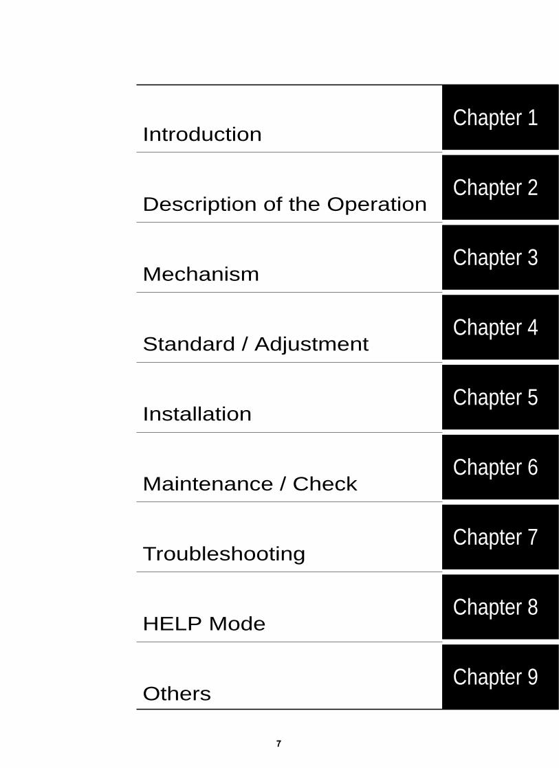
Chapter 8
Chapter 7
Chapter 6
Chapter 5
Chapter 4
Chapter 3
Chapter 2
Chapter 1
Troubleshooting
HELP Mode
Chapter 9Others
Maintenance / Check
Installation
Standard / Adjustment
Mechanism
Description of the Operation
Introduction

8

9
Table of Contents
Chapter 1
z Features................................................................................12x Specifications ......................................................................14c Dimensions ..........................................................................16v Mechanism ...........................................................................17b Master ...................................................................................18n Ink..........................................................................................19m System Setup .......................................................................20, Part Names and Their Functions........................................21. Operation Procedures .........................................................29⁄0 Error Messages and Corrective Action .............................30
Chapter 2
z Scanner Section.........................................................55x Mastermaking/Master Feed/Ejection Section......... 59c Paper Feed Section....................................................82v Drum Driving Section................................................95b Press Section............................................................101n Paper Ejection Section............................................104m Drum Section...........................................................109
Chapter 3
z Exterior.....................................................................119x Scanner Section.......................................................125c Mastermaking/Master Feed/Ejection Section....... 131v Paper Feed Section..................................................140b Drum Driving Section..............................................145n Paper Ejection Section............................................147m Drum Section...........................................................150
Chapter 4
z Scanner Section.......................................................159x Mastermaking/Master Feed/Ejection Section........161c Paper Feed Section..................................................169v Drum Driving Section..............................................174b Press Section...........................................................176n Paper Ejection Section............................................178m Drum Section...........................................................179, Electrical System.....................................................183
Chapter 5
z DUPRINTER Installation Instructions....................192
Chapter 7
z Troubleshooting Guide............................................208x Error Display............................................................223
Chapter 8
Chapter 9
z Electrical Parts Layout and Their Functions.........308x Overall Wiring Layout..............................................314
z HELP Mode List.......................................................226x Overview...................................................................230c HELP Mode Functions and Operation Procedures .......231
(1)Basic Procedure for Accessing HELP Modes...231(2)Guide to the HELP Mode Descriptions..............231
• HELP Mode Descriptions.....................................233
Introduction.................................................................................1Using the service manual ..........................................................2
Safety instructions ...............................................................31.Cautions regarding the installation location........................32.Cautions for installation work ...............................................43.Cautions for maintenance, inspection and servicing .........5• Locations of warning stickers................................................6
Troubleshooting
Chapter 6
z Guaranteed Periodical Maintenance......................204x Cleaning and Oiling.................................................204c Periodical Maintenance...........................................205
Maintenance / Check
Installation
Standards / Adjustment
HELP Mode
Others
Mechanism
Description of the Operation
Introduction
(3)Guide to version up.............................................232

10

11
z Features ........................................................................12
x Specifications...............................................................14
c Dimensions...................................................................16
v Mechanism ...................................................................17
b Master ...........................................................................18
n Ink..................................................................................19
m System Setup ...............................................................20
, Part Names and Their Functions................................211. Machine exteriors ....................................................212. Sectional (structural) view of the machine ...........243. Control Panel ..........................................................26
. Operation Procedures .................................................291. Mastermaking & Printing........................................ 29
⁄0 Error Messages and Corrective Action......................301. Error messages .......................................................302. Corrective action .....................................................32
(1) Replacing the Ink Pack ......................................32(2) Replacing the Master Roll .................................34(3) Replacing the Master Ejection Core..................37(4) Supplying Paper ................................................39(5) Replacing the Drum Unit ..................................43(6) Paper Jam (Feeder side).....................................45(7) Paper Jam (Ejection side) ..................................46(8) Master is Not Ejected.........................................49(9) Master Set Incorrectly
("MASTER SET MISS"is displayed)..................51
1Chapter 1 Introduction
(1) Key outside of the panel cover...........................26
(2) LCD Panel...........................................................28

12
chap.1 z Features
Size A/B models • Zoom settings (70, 81, 86, 115, 122, 141%) • Same-size (100%) printing
Free zoom 50% -200% ( 1% )141% [B5/B4, A5/A4]122% [A4/B4, A5/B5]115% [B5/A4]86% [A3/B4, A4/B5]81% [B4/A4, B5/A5]70% [A3/A4, B4/B5]
Free zoom 50% -200% ( 1% )141% [A5/A4]122% [A5/B5]115% [B5/A4]86% [A4/B5]81% [B4/A4]70% [A3/A4, B4/B5]
Inch size model • Zoom settings (64, 74, 77, 121, 129, 141%) • Same-size (100%) printing
Free zoom 50% -200% ( 1% )141%129% [ST/LTR]121%77% [LGL/LTR]74% [LDG/LGL]67% [LDG/LTR]
Enlargement
Reduction
Enlargement
Reduction
Enlargement
Reduction
zFeatures
1. Size B4 printing (DP-M420)The has size B4 (250 X355mm) printing area.The has size LG(210 X347mm) printing area.The has size A4 (204X288mm) printing area.
2. High-speed platemakingWith the , it takes 21 seconds *1 toprint the first sheet of paper(A4,100%).
*1: Time required to print the first sheet of paper afterthe mastermaking key is pressed.
3. High print qualityA new, originally-developed superfine thermal headgives beautifully accurate reproductions of fine printand halftone photographs.Its resolution is 300dpi in the main scanningdirection and 600dpi in the sub scanning direction.
4. Align paperAdjusting the eject enables both thin and thicksheets of paper to be aligned neatly.
5. High-performance lampA long-life, high-brightness xenon arc lamp is usedto illuminate the documents. Since the lamp'sintensity is not affected by temperature variation*2,printing quality at low temperatures is greatlyenhanced*3.
*2: The lamp is filled with xenon gas, which means that itdoes not require heat to vaporize mercury, as afluorescent lamp does, and therefore its intensity doesnot vary with temperature.
*3: Increased viscosity of the ink at low temperaturesresults in fainter print ing than at normaltemperatures.
6. Full range of necessary functionsqDocuments are easily enlarged or reduced.
In addition to same-size printing, there are threeautomatic settings for both enlargement andreduction. The margin function (94% reduction)can be used with any setting.
DP-M420
DP-M410
DP-M400
DP-M420DP-M410DP-M400
DP-M400/410/420

13
chap.1 z Features
7. OptionsqADF
Use of the ADF permits continuousmastermaking and pr int ing o f 100documents (64gsm ).The ADF 's tray fits completely inside theADF,so as not to interfere with loading/removal of printing paper.
wTAPE CLUSTERThis permits sectionized printing, byinserting tape automatically duringprinting.
e
r
DrumsReplacing the drum with optional drumspermits printing with different colors.
On-line functions *4
These enable data processed on a personalcomputer or word processor to be directlyinput and used for platemaking/printing.
*4: This function require PC interface.
wSelf-diagnosisThe machine has a self-diagnosis system,which notices user by flashing on and offa message and lighting up the relevantlamp when a expendable part needsreplacing.
eError message displayAn LCD panel displays error messages andmessages prompting replenishment ofconsumables.
r2 in 1 Layout modeIn conjunction with an ADF ( optional ),this mode makes possible continuousprinting of 2 documents onto single sheetsof paper.
tAdjusting the Printing Position (vertical)In addi t ion to ver t i ca l d i rec t ionadjustment.
t Auto Power Off KitThis kit can turn off the machine automatic when there is no operation within5 minutes.
yUID control functionRaises the number of sections controlledto up to 100.
uMemory functionAllows 9 sets of memory settings.
Ink save modeThis mode can save ink.
8
Energy save modeThis mode can turn off the backlight
9
of LCD and the LED light on panel,when there is no operation within 3 minutes in order to save energy.
14
chap.1 x Specifications
xSpecifications
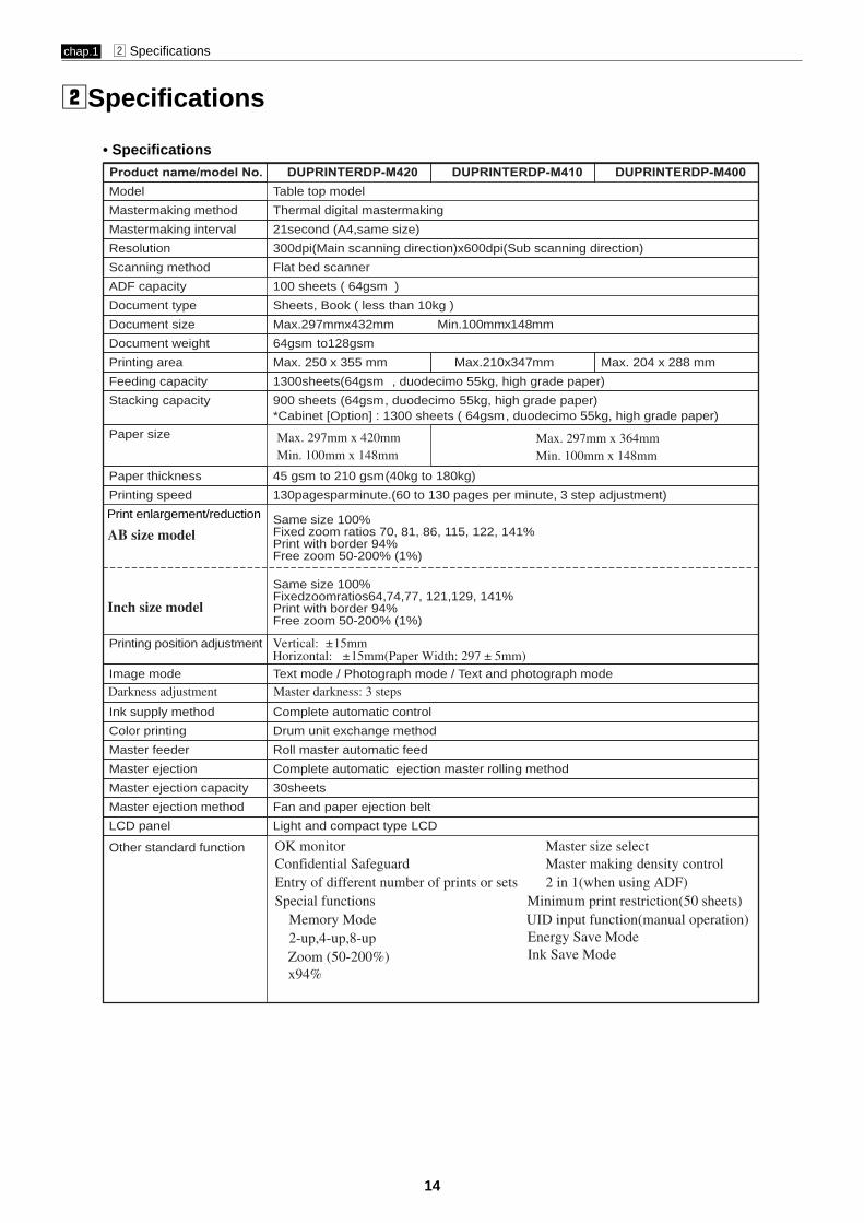
• SpecificationsProduct name/model No. DUPRINTERDP-M420 DUPRINTERDP-M410 DUPRINTERDP-M400Model Table top model
Mastermaking method Thermal digital mastermaking
Mastermaking interval 21second (A4,same size)
Resolution 300dpi(Main scanning direction)x600dpi(Sub scanning direction)
Scanning method Flat bed scanner
Document type
100 sheets ( 64gsm )
Document size
Sheets, Book ( less than 10kg )
Document weight
Max.297mmx432mm Min.100mmx148mm
64gsm to128gsm
Printing area
Feeding capacity
Max. 250 x 355 mm
Stacking capacity
1300sheets(64gsm , duodecimo 55kg, high grade paper)
Paper size
900 sheets (64gsm, duodecimo 55kg, high grade paper)*Cabinet [Option] : 1300 sheets ( 64gsm, duodecimo 55kg, high grade paper)
ADF capacity
Max.210x347mm Max. 204 x 288 mm
Paper thickness 45 gsm to 210 gsm(40kg to 180kg)
Printing speed 130pagesparminute.(60 to 130 pages per minute, 3 step adjustment)
Same size 100%Fixed zoom ratios 70, 81, 86, 115, 122, 141%PrintFree zoom 50-200% (1%)
with border 94%
Same size 100%Fixedzoomratios64,74,77, 121,129, 141%PrintFree zoom 50-200% (1%)
with border 94%
Printing position adjustment
Image mode Text mode / Photograph mode / Text and photograph mode
Ink supply method Complete automatic control
Color printing Drum unit exchange method
Master feeder Roll master automatic feed
Master ejection Complete automatic ejection master rolling method
Master ejection capacity 30sheets
Master ejection method Fan and paper ejection belt
LCD panel Light and compact type LCD
Other standard function
Print enlargement/reduction
Max. 297mm x 364mmMin. 100mm x 148mm
Max. 297mm x 420mmMin. 100mm x 148mm
AB size model
Inch size model
Vertical: ±15mmHorizontal: ±15mm(Paper Width: 297 ± 5mm)
Darkness adjustment Master darkness: 3 steps
OK monitorConfidential Safeguard
Zoom (50-200%)
Entry of different number of prints or setsSpecial functions
Memory Mode2-up,4-up,8-up
UID input function(manual operation)Energy Save Mode
Master size selectMaster making density control2 in 1(when using ADF)
Minimum print restriction(50 sheets)
Ink Save Modex94%
15
chap.1 x Specifications
• Specifications
Product name/model
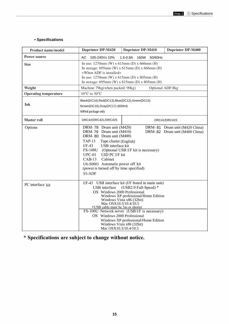
Power source
Size
Weight Machine 79kg(when packed: 90kg) Optional ADF:8kg
Operating temperature 10°C to 30°C
Duprinter DP-M420 Duprinter DP-M410 Duprinter DP-M400
600ml package only
Black(DC14),Red(DC13),Blue(DC12),Green(DC15)
Brown(DC16),Gray(DC17) (600ml)
DRC41/DRC415
Ink
Master roll
* Specifications are subject to change without notice.
Options ・ DRM- Drum unit (M420)・ DRM- Drum unit (M410)・ DRM- Drum unit (M400)・・
TAP-13 Tape cluster
・I/F-43 USB interface kit
・FS-100U (Optional USB I/F kit is necessary)
・UID PC I/F kit
・CAB-13 Cabinet
・Automatic power off kit
(power is turned off by time specified)
PC interface kit・
・
AC 100-240V±10%
787980
In use: 1270mm (W) x 615mm (D) x 666mm (H)In storage: 695mm (W) x 615mm (D) x 666mm (H)<When ADF is installed>In use: 1270mm (W) x 615mm (D) x 805mm (H)In storage: 695mm (W) x 615mm (D) x 805mm (H)
1.6-0.8A 160W 50/60Hz
DRC42/DRC42L/DRC425
DRM- Drum unitDRM- Drum unit
8182
(M420 China)(M400 China)
(English)
UPC-01
U6-S0001
S5-ADF
USB interface kit (I/F board in main unit)USB interface (USB2.0 Full-Speed) *
FS-100U (USB I/F is necessary)OS:
I/F-43
*USB cable must be 3m or shorterNetwork serverWindows 2000 ProfessionalWindows XP professional/Home EditionWindows Vista x86 (32bit)Mac OSX10.3/10.4/10.5
OS:
Windows 2000 ProfessionalWindows XP professional/Home EditionWindows Vista x86 (32bit)Mac OSX10.3/10.4/10.5

16
chap.1 c Dimensions
cDimensions
(mm)
563
666.
5
517
229 470
1262
615
472
105
380
478
130
915

17
chap.1 v Mechanism
The machine carries out the processes of “mastermaking” and “printing.”
Mastermaking
In the “mastermaking” process, the old master on the drum is removed while thethermal head creates the scanned image on the new master and transfers it onto thedrum.
Printing
In the “printing” process, paper separated from the stack by the paper feed roller andthe paper separator unit is pressed against the drum unit by the press roller. There aresmall holes over only the image area of the master that is attached to the drum, and inkthat seeps from these holes is transferred to the paper. The paper is then peeled fromthe master by the paper stripper finger. The paper is directed onto the paper ejectionbelt by a fan unit and discharged from the machine.
vMechanism
Master roll Master ejection box
Drumunit
Thermal head
Drum unit
Feeder roller
Paper
Paper sepatator unit
Press roller
Paper stripper finger
Paper ejection belt
Fan unit
18
chap.1 b Master
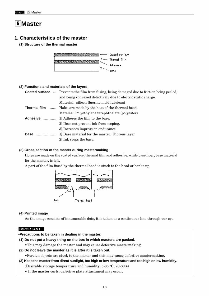
1. Characteristics of the master(1) Structure of the thermal master
(2) Functions and materials of the layersCoated surface … Prevents the film from fusing, being damaged due to friction,being peeled,
and being conveyed defectively due to electric static charge.Material: silicon fluorine mold lubricant
Thermal film …… Holes are made by the heat of the thermal head.Material: Polyethylene terephthalate (polyester)
Adhesive ………… 1] Adheres the film to the base.2] Does not prevent ink from seeping.3] Increases impression endurance.
Base ……………… 1] Base material for the master. Fibrous layer2] Ink seeps the base.
(3) Cross section of the master during mastermakingHoles are made on the coated surface, thermal film and adhesive, while base fiber, base materialfor the master, is left.A part of the film fused by the thermal head is stuck to the head or banks up.
(4) Printed imageAs the image consists of innumerable dots, it is taken as a continuous line through our eye.
IMPORTANT : •Precautions to be taken in dealing in the master.
(1) Do not put a heavy thing on the box in which masters are packed.•This may damage the master and may cause defective mastermaking.
(2) Do not leave the master as it is after it is taken out.•Foreign objects are stuck to the master and this may cause defective mastermaking.
(3) Keep the master from direct sunlight, too high or low temperature and too high or low humidity.(Desirable storage temperature and humidity: 5-35 °C, 20-80%)• If the master curls, defective plate attachment may occur.
bMaster

19
chap.1 n Ink
IMPORTANT : • Precautions to be taken in handling ink
(1) Storage environment• When an emulsion type ink is stored at too high or low temperature for a long time, oil and water in the
ink pack may be isolated. Keep the ink from too high or low temperature (5°C or less, 35°C or more).Also keep the ink from direct sunlight since the temperature rises sharply in the direct sunlight.
• When the water content is frozen, the water content is solidified and the bond characteristics decreases.• When ink is stored at a high temperature, the bond characteristics decreases due to the change of the
surface conditions (surface tension, solubility). The bond characteristics also decreases due to evaporatinof the water content.
(2) Precautions to be taken in handling the ink pack• When the ink pack is removed from the drum unit to store, put the ink pack with its mouth up, screw
the cap firmly after expelling air from the ink tube. (If air is in the ink pack, water content is generated.)
1. Characteristics of ink(1)Ink type Ink for the digital printer is an emulsion type . It has a water-in-oil type structure. •Emulsion type
(2) 2 characteristics The surface active agent has 2 characteristics: hydrophilic group and lipophilic group in 1 molecule. Oil and water bond together by these 2 characteristics as shown in the figure.
(3) Temperature Ink viscosity is high at a low temperature and it is low at a high temperature. So when ink is used at a
low temperature (10°C or less), the amount of ink transferred to the paper is smaller and the printdarkness is slightly lighter.When ink is used at a high temperature (30°C or more), the amount of ink transferred to the paper is larger and the print darkness is slightly darker.
nInk

20
chap.1 m System Setup
mSystem Setup
The machine and its optional equipment are set up as follows:
• DDP systemDocuments prepared on a personal computer can be printed on this machine.The PC interface kit is required to connect this machine to a personal computer.
NOTE :
Duplo Direct Print System
Drum unit : Option
TAPE CLUSTER 13
Cabinet (Printer stand)
Personal computer
S5-ADF

21
chap.1 , Part Names and Their Functions
,Part Names and Their Functions
1. Machine exteriors
Document cover
Scanner
Control panel
Front cover
Scanner switch
Feed tray descend switch
Feed pressure adjuster lever
Slide guides
Feed tray
Supplemental paper tray
Power switch
Cabinet Optional (Printer stand)
Caster locks
22
chap.1 , Part Names and Their Functions
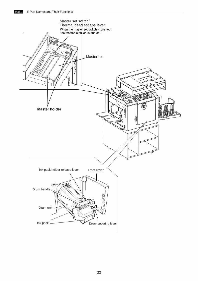
Master roll
Ink pack holder release lever Front cover
Drum handle
Drum unit
Ink pack Drum securing lever
Master set switch/Thermal head escape lever
Master holder
When the master set switch is pushed,the master is pulled in and set.

23
chap.1 , Part Names and Their Functions
Master ejection box release lever
(Drum rotator switch)
Print tray
Paper stopper
Paper stacker guides
Master ejection core
Master ejection boxMaster ejection box
Master ejection box lid release lever
Jamp plate
JOG switch

24
chap.1 , Part Names and Their Functions
2. Sectional (structural) view of the machine
2
3
2A1
6
2B
4,8
2C

25
chap.1 , Part Names and Their Functions
No.
1
2
2A
2B
2C
3
4
5
6
7
8
Section Name
Scanner section
Mastermaking/Master feed/ejection section
Mastermaking/Master feed section
Master ejection section
Master clamp opening/closing section
Paper feed section
Drum driving section
Press section
Paper ejection section
Print tray
Drum section
55page
59page
59page
74page
76page
82page
95page
101page
104page
4
109page
Mechanism
125page
131page
131page
136page
138page
140page
145page
4
147page
4
150page
Srandard/Adjustment
159page
161page
161page
162page
164page
169page
174page
176page
178page
4
179page
Description of the Operation
1
6
2B
4,8
1
6
2B
7
4,8
24S067

26
chap.1 , Part Names and Their Functions
3. Control Panel
No. Name Function
q
“OK” monitor Flashes to display the content of the trouble and lights to indicatedthe part that caused the trouble in the machine.
w
/REDUCTION” keyPress to set the enlargement or 100% or reduction ratio.
e
“DOCUMENT MODE Press to switch between the text mode, text/photograph mode andphotograph mode. Each press of this key moves the position of thelit lamp that indicates the selected document mode.
Document modeThe lamp of the selected mode lights.
r
LCD panelDisplays the number of printed paper.Also displays an error message when an error occurs.
t
“FUNCTION SWITCH” key Press to toggle between the normal mode and the function select mode.“LEFT SELECT” key Press to select left function.
y
u
Referencepage
93
39
39
47
47
24, 93
5252
SWITCH” key
qw
e
r
t
y
u
“RIGHT SELECT” key Press to select right function.
“ENLARGEMENTIndiction for the ratio is selected.
/REDUCTION” lamp
“ENLARGEMENT
indicator lamps
52
0sht 1set100%
(1).Key outside of the panel cover

27
No. Name Function
i
“STOP” keyPress to stop printing on the way.If this key is pressed while the machine is stopped,the total number of prints and masters will be displayedon the LCD panel.
o
“PRINT” keyStarts printing. This will not start mastermaking.Mastermaking will start automatically after the end ofprinting if there is a document on the ADF.
!0
“ALL CLEAR” keyReturns the control panel settings to the “StandardMode” settings. Press and hold for at least 0.5seconds.
!1
X= keyPress to enter the number of prints and number of setsfor sectional prints.
!2
Key pad Use to enter the number of prints.
!3
“CLEAR” keyPress to reset the displayed number of prints to “0”.Only the number of prints is cleared.
!4
Printing speed indicator lamp
The lamp of the specified printing speed lights.
!5
“PRINTING SPEED ADJUSTMENT” keys Press to adjust the printing speed.!6
“PRINTING POSITION ADJUSTMENT” keys Press to adjust the printing position.
!7
Printing position indicator lamp
The lamp of the specified printing speed lights.
Referencepage
65
33
73
74
75
i o !0
“TEST PRINT” key Press to print only one piece of paper for checking the print darkness or printed position.
“MASTERMAKING” key Press to start mastermaking.
32
!
!
2
8
9
0
Energy saving mode indicator lamp The lamp of the energy saving mode.
2 0
!1 !2 !3
!4
!5
!7 !6!8!9
72
33
33
33
76
75
74
chap.1 , Part Names and Their Functions

28
chap.1 , Part Names and Their Functions
(2). LCD Panel
No. Name Function
q Print count Displays the number of prints to be made.
w Sets Displays the number of sets to be printed.e Zoom ratio Displays the selected (enlargement/reduction)ratio.
Referencepage
33
65
0sht 1set
q w e
100%

29
chap.1 . Operation Procedures
.Operation Procedures
1. Mastermaking & Printing
Printing speed adjustment / keys
Printing position adjustment / keys
1 Set document
2 Mastermaking key
4 Print key
3 Input the number of printsand the number of sets
5 End
Function switch keySelect key
Document mode switch key
Test print keyT
Reduction is selected.
Document size is selected.
Photograph mode is selected.
Master darkness is switched.
Selects Texts, Text/Photograph &Photograph mode.
When the number of prints is input in advance, printing starts automaticallyafter mastermaking.
Printing position is adjusted.
Printing speed is adjusted.
Printing is tested (a sheet of paper.)
Input the number of prints and the number of sets on the key pad.
30
chap.1 ⁄0 Error Messages and Corrective Action
1. Error messages
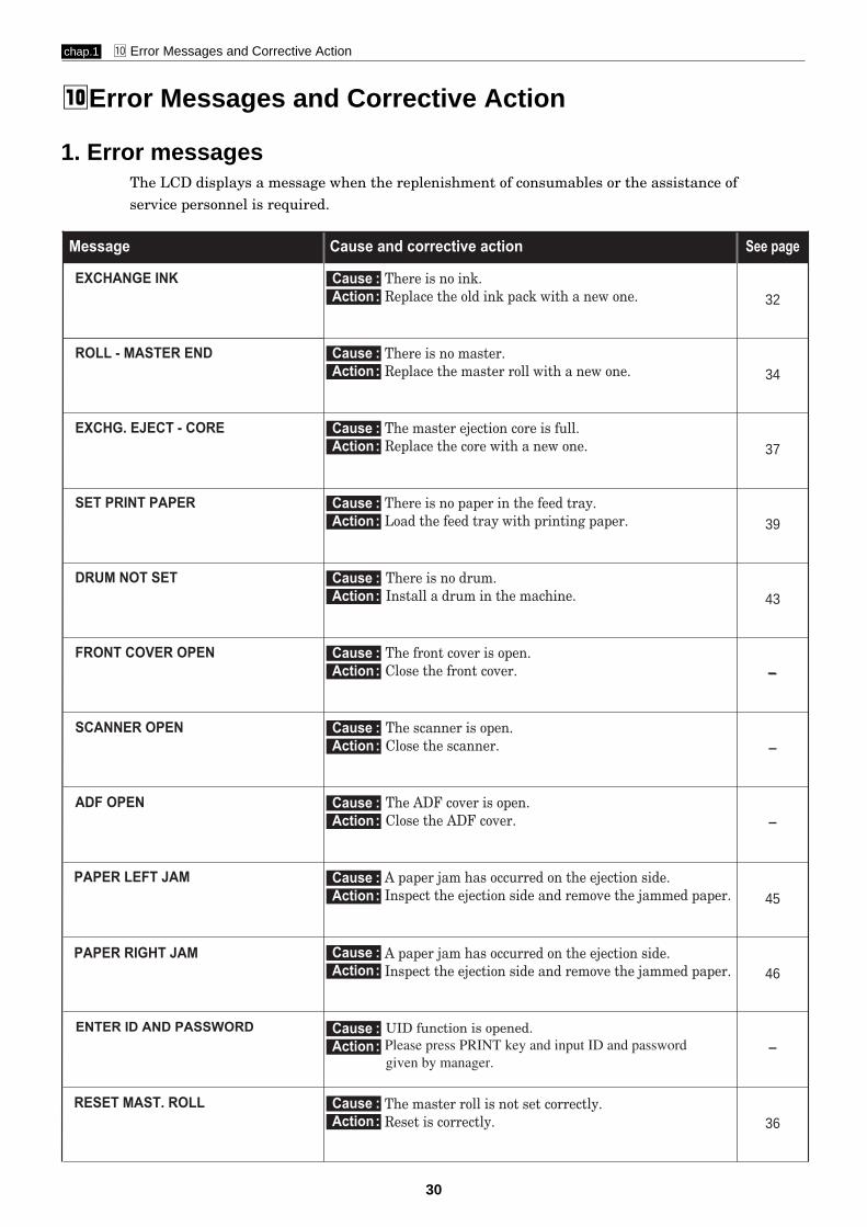
⁄0Error Messages and Corrective Action
The LCD displays a message when the replenishment of consumables or the assistance ofservice personnel is required.
Message See page
32
34
37
39
43
44
4
4
Cause and corrective action
There is no ink. Replace the old ink pack with a new one.
Cause :Action:
Cause :Action:
Cause :Action:
Cause :Action:
Cause :Action:
Cause :Action:
Cause :Action:
Cause :Action:
Cause :Action:
Cause :Action:
Cause :Action:
Cause :Action:
There is no master. Replace the master roll with a new one.
The master ejection core is full. Replace the core with a new one.
There is no paper in the feed tray. Load the feed tray with printing paper.
There is no drum. Install a drum in the machine.
The front cover is open. Close the front cover.
The scanner is open. Close the scanner.
The ADF cover is open. Close the ADF cover.
EXCHANGE INK
ROLL - MASTER END
EXCHG. EJECT - CORE
SET PRINT PAPER
DRUM NOT SET
FRONT COVER OPEN
SCANNER OPEN
ADF OPEN
A paper jam has occurred on the ejection side. Inspect the ejection side and remove the jammed paper.
The master roll is not set correctly.Reset is correctly.
PAPER RIGHT JAM
A paper jam has occurred on the ejection side. Inspect the ejection side and remove the jammed paper.
PAPER LEFT JAM
RESET MAST. ROLL
45
46
4
36
UID function is opened.ENTER ID AND PASSWORDPlease press PRINT key and input ID and passwordgiven by manager.

31
chap.1 ⁄0 Error Messages and Corrective Action
Message See page
51
223
4
4
4
Cause and corrective action
There is an error during master setting. Open the top cover and remove the master that is left in the master feeder.
The document is jammed on the ADF. Open the ADF cover and remove the jammed document.
The printer is not ready. Please wait with the power ON.
4
Cannot print.This message is displayed if you press (PRINT) or (TEST PRINT) keys without making a plate immediately after a master setting error or when the confidential safeguard function is ON.
4
Printing is not complete. Either press (PRINT) key to resume printing or press (CLEAR) key to clear the counter.C
T
PLS MASTER MAKING
PRINTING
MASTER SET MISS
MAST. EJECT MISS
DOCUMENT JAM
--- WAIT---
There is an old master on the drum. Remove all the masters from the drum. 49
•If the message remains after a few minutes, turn the power OFF and ON again.
•If the message still remains after a few minutes, turn the power OFF and contact your service person.
•Report the error code and details of error occurrence to service personnel.
Cause :Action:
Cause :Action:
Cause :Action:
Cause :Action:
Action:
Cause :Action:
Follow the procedure below.qRecord the error message "E***".w Shut off the power and turn it back on.eIf the message is displayed again, contact service personnel.
SERVICE CALL( "E***" flashes )
Action:
Cause :Action:
* For displayed messages other than those listed above, refer to Chapter 7"Troubleshooting". a See page 207
ID or PASSWORD is not correct.ID OR PASSWORD NOT CORRECTPlease press key or PRINT key and input correct ID and password again.

32
chap.1 ⁄0 Error Messages and Corrective Action
IMPORTANT :• Only use ink packs designed for this machine.
○ ○ ○ ○ ○ ○ ○ ○ ○ ○ ○ ○ ○ ○ ○ ○ ○ ○ ○ ○ ○ ○ ○ ○ ○ ○ ○ ○ ○ ○ ○ ○ ○
Open the front cover.
○ ○ ○ ○ ○ ○ ○ ○ ○ ○ ○ ○ ○ ○ ○ ○ ○ ○ ○ ○ ○ ○ ○ ○ ○ ○ ○ ○ ○ ○ ○ ○ ○
Grasp the lever and pull it toward you.
○ ○ ○ ○ ○ ○ ○ ○ ○ ○ ○ ○ ○ ○ ○ ○ ○ ○ ○ ○ ○ ○ ○ ○ ○ ○ ○ ○ ○ ○ ○ ○ ○
Lift out the empty ink pack.
○ ○ ○ ○ ○ ○ ○ ○ ○ ○ ○ ○ ○ ○ ○ ○ ○ ○ ○ ○ ○ ○ ○ ○ ○ ○ ○ ○ ○ ○ ○ ○ ○
Remove the cap from a new ink pack.
IMPORTANT :• Do not leave an ink pack uncapped for longer
than necessary.
○ ○ ○ ○ ○ ○ ○ ○ ○ ○ ○ ○ ○ ○ ○ ○ ○ ○ ○ ○ ○ ○ ○ ○ ○ ○ ○ ○ ○ ○ ○ ○ ○ ○ ○ ○ ○ ○ ○ ○ ○ ○ ○ ○ ○ ○ ○ ○ ○ ○ ○ ○ ○ ○ ○ ○ ○ ○ ○ ○ ○
2. Corrective action
(1) Replacing the Ink Pack
Front cover
Ink pack
Lever
Ink pack

33
chap.1 ⁄0 Error Messages and Corrective Action
○ ○ ○ ○ ○ ○ ○ ○ ○ ○ ○ ○ ○ ○ ○ ○ ○ ○ ○ ○ ○ ○ ○ ○ ○ ○ ○ ○ ○ ○ ○ ○ ○
Insert the ink pack so that the groove on the lipfits onto the “U” groove of the holder.
○ ○ ○ ○ ○ ○ ○ ○ ○ ○ ○ ○ ○ ○ ○ ○ ○ ○ ○ ○ ○ ○ ○ ○ ○ ○ ○ ○ ○ ○ ○ ○ ○
Push the ink pack in to the set line on the inkpack.
○ ○ ○ ○ ○ ○ ○ ○ ○ ○ ○ ○ ○ ○ ○ ○ ○ ○ ○ ○ ○ ○ ○ ○ ○ ○ ○ ○ ○ ○ ○ ○ ○
Press the back of the holder in with the palm ofyour hand.
○ ○ ○ ○ ○ ○ ○ ○ ○ ○ ○ ○ ○ ○ ○ ○ ○ ○ ○ ○ ○ ○ ○ ○ ○ ○ ○ ○ ○ ○ ○ ○ ○
Close the front cover.
○ ○ ○ ○ ○ ○ ○ ○ ○ ○ ○ ○ ○ ○ ○ ○ ○ ○ ○ ○ ○ ○ ○ ○ ○ ○ ○ ○ ○ ○ ○ ○ ○ ○ ○ ○ ○ ○ ○ ○ ○ ○ ○ ○ ○ ○ ○ ○ ○ ○ ○ ○ ○ ○ ○ ○ ○ ○ ○ ○ ○
Set line
Set line
Front cover
"U" groove of holder

34
chap.1 ⁄0 Error Messages and Corrective Action
IMPORTANT :• Only use a master roll designed for use in this machine.
(2) Replacing the Master Roll
○ ○ ○ ○ ○ ○ ○ ○ ○ ○ ○ ○ ○ ○ ○ ○ ○ ○ ○ ○ ○ ○ ○ ○ ○ ○ ○ ○ ○ ○ ○ ○ ○
Slide the scanner unit.
• Do not touch the heat generator of thermalhead. Doing so may cause damages, leadingto a malfunction of mastermaking.
○ ○ ○ ○ ○ ○ ○ ○ ○ ○ ○ ○ ○ ○ ○ ○ ○ ○ ○ ○ ○ ○ ○ ○ ○ ○ ○ ○ ○ ○ ○ ○ ○
○ ○ ○ ○ ○ ○ ○ ○ ○ ○ ○ ○ ○ ○ ○ ○ ○ ○ ○ ○ ○ ○ ○ ○ ○ ○ ○ ○ ○ ○ ○ ○ ○
○ ○ ○ ○ ○ ○ ○ ○ ○ ○ ○ ○ ○ ○ ○ ○ ○ ○ ○ ○ ○ ○ ○ ○ ○ ○ ○ ○ ○ ○ ○ ○ ○ ○ ○ ○ ○ ○ ○ ○ ○ ○ ○ ○ ○ ○ ○ ○ ○ ○ ○ ○ ○ ○ ○ ○ ○ ○ ○ ○ ○
master holder
Lift out the master roll,then remove the masterholder from the master roll.
Pull out the master.Turn the master holder toward you whilepushing the thermal head escape lever.Pull out the master.
Master roll
IMPORTANT
Scanner unit

35
chap.1 ⁄0 Error Messages and Corrective Action
○ ○ ○ ○ ○ ○ ○ ○ ○ ○ ○ ○ ○ ○ ○ ○ ○ ○ ○ ○ ○ ○ ○ ○ ○ ○ ○ ○ ○ ○ ○ ○ ○ ○ ○ ○ ○ ○ ○ ○ ○ ○ ○ ○ ○ ○ ○ ○ ○ ○ ○ ○ ○ ○ ○ ○ ○ ○
Take out a new master roll from the bag.
○ ○ ○ ○ ○ ○ ○ ○ ○ ○ ○ ○ ○ ○ ○ ○ ○ ○ ○ ○ ○ ○ ○ ○ ○ ○ ○ ○ ○ ○ ○ ○ ○
Set the master roll in the direction as shown inthe illustration at right.
○ ○ ○ ○ ○ ○ ○ ○ ○ ○ ○ ○ ○ ○ ○ ○ ○ ○ ○ ○ ○ ○ ○ ○ ○ ○ ○ ○ ○ ○ ○ ○ ○
○ ○ ○ ○ ○ ○ ○ ○ ○ ○ ○ ○ ○ ○ ○ ○ ○ ○ ○ ○ ○ ○ ○ ○ ○ ○ ○ ○ ○ ○ ○ ○ ○
○ ○ ○ ○ ○ ○ ○ ○ ○ ○ ○ ○ ○ ○ ○ ○ ○ ○ ○ ○ ○ ○ ○ ○ ○ ○ ○ ○ ○ ○ ○ ○ ○
• If the master is not pulled in open the mastercover, and gently press in as far as possibleto set again.
○ ○ ○ ○ ○ ○ ○ ○ ○ ○ ○ ○ ○ ○ ○ ○ ○ ○ ○ ○ ○ ○ ○ ○ ○ ○ ○ ○ ○ ○ ○ ○ ○ ○ ○ ○ ○ ○ ○ ○ ○ ○ ○ ○ ○ ○ ○ ○ ○ ○ ○ ○ ○ ○ ○ ○ ○ ○ ○ ○ ○
master holder
Insert the master roll into the machine
the control panel.
Peel off the seal.
Pull out the master and insert the front
head of the master until it contacts the roller.
SEAL
IMPORTANT

36
chap.1 ⁄0 Error Messages and Corrective Action
○ ○ ○ ○ ○ ○ ○ ○ ○ ○ ○ ○ ○ ○ ○ ○ ○ ○ ○ ○ ○ ○ ○ ○ ○ ○ ○ ○ ○ ○ ○ ○ ○
○ ○ ○ ○ ○ ○ ○ ○ ○ ○ ○ ○ ○ ○ ○ ○ ○ ○ ○ ○ ○ ○ ○ ○ ○ ○ ○ ○ ○ ○ ○ ○ ○
○ ○ ○ ○ ○ ○ ○ ○ ○ ○ ○ ○ ○ ○ ○ ○ ○ ○ ○ ○ ○ ○ ○ ○ ○ ○ ○ ○ ○ ○ ○ ○ ○ ○ ○ ○ ○ ○ ○ ○ ○ ○ ○ ○ ○ ○ ○ ○ ○ ○ ○ ○ ○ ○ ○ ○ ○ ○ ○ ○ ○
Push the master set switch.The master will be pulled in, and cut automatically.If the master does not go in, pull the master back.
Remove the trimmed piece of the master.
¡¡If the master is wrinkled:push and hold the
master set switch again, and push downthe thermal head escape lever 2 or 3 times.
¡¡When the master stops, make sure thatyou remove the trimmed piece of themaster.
¡¡The cutter operates and stops after themaster is cut.Remove the cut piece left inside themachine.
THERMAL HEADESCAPE LEVER
MASTER SET SWITCH
IMPORTANT
IMPORTANT
37
chap.1 ⁄0 Error Messages and Corrective Action
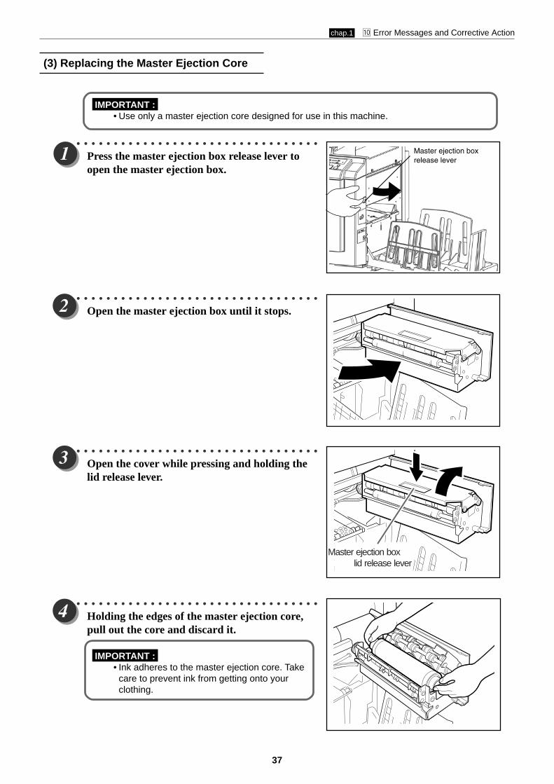
IMPORTANT :• Use only a master ejection core designed for use in this machine.
○ ○ ○ ○ ○ ○ ○ ○ ○ ○ ○ ○ ○ ○ ○ ○ ○ ○ ○ ○ ○ ○ ○ ○ ○ ○ ○ ○ ○ ○ ○ ○ ○
Press the master ejection box release lever toopen the master ejection box.
○ ○ ○ ○ ○ ○ ○ ○ ○ ○ ○ ○ ○ ○ ○ ○ ○ ○ ○ ○ ○ ○ ○ ○ ○ ○ ○ ○ ○ ○ ○ ○ ○
Open the master ejection box until it stops.
○ ○ ○ ○ ○ ○ ○ ○ ○ ○ ○ ○ ○ ○ ○ ○ ○ ○ ○ ○ ○ ○ ○ ○ ○ ○ ○ ○ ○ ○ ○ ○ ○
Open the cover while pressing and holding thelid release lever.
○ ○ ○ ○ ○ ○ ○ ○ ○ ○ ○ ○ ○ ○ ○ ○ ○ ○ ○ ○ ○ ○ ○ ○ ○ ○ ○ ○ ○ ○ ○ ○ ○
Holding the edges of the master ejection core,pull out the core and discard it.
IMPORTANT :• Ink adheres to the master ejection core. Take
care to prevent ink from getting onto yourclothing.
(3) Replacing the Master Ejection Core
Master ejection box lid release lever
Master ejection boxrelease lever

chap.1 ⁄0 Error Messages and Corrective Action
38
○ ○ ○ ○ ○ ○ ○ ○ ○ ○ ○ ○ ○ ○ ○ ○ ○ ○ ○ ○ ○ ○ ○ ○ ○ ○ ○ ○ ○ ○ ○ ○ ○ ○ ○ ○ ○ ○ ○ ○ ○ ○ ○ ○ ○ ○ ○ ○ ○ ○ ○ ○ ○ ○ ○ ○ ○ ○
Insert a new master ejection core.
○ ○ ○ ○ ○ ○ ○ ○ ○ ○ ○ ○ ○ ○ ○ ○ ○ ○ ○ ○ ○ ○ ○ ○ ○ ○ ○ ○ ○ ○ ○ ○ ○
Gently close the master ejection box cover,pressing it until it locks.
○ ○ ○ ○ ○ ○ ○ ○ ○ ○ ○ ○ ○ ○ ○ ○ ○ ○ ○ ○ ○ ○ ○ ○ ○ ○ ○ ○ ○ ○ ○ ○ ○
Close the master ejection box, pressing it until itlocks.
○ ○ ○ ○ ○ ○ ○ ○ ○ ○ ○ ○ ○ ○ ○ ○ ○ ○ ○ ○ ○ ○ ○ ○ ○ ○ ○ ○ ○ ○ ○ ○ ○ ○ ○ ○ ○ ○ ○ ○ ○ ○ ○ ○ ○ ○ ○ ○ ○ ○ ○ ○ ○ ○ ○ ○ ○ ○ ○ ○ ○

chap.1 ⁄0 Error Messages and Corrective Action
39
○ ○ ○ ○ ○ ○ ○ ○ ○ ○ ○ ○ ○ ○ ○ ○ ○ ○ ○ ○ ○ ○ ○ ○ ○ ○ ○ ○ ○ ○ ○ ○ ○
Open the supplemental paper tray if it is closed.
○ ○ ○ ○ ○ ○ ○ ○ ○ ○ ○ ○ ○ ○ ○ ○ ○ ○ ○ ○ ○ ○ ○ ○ ○ ○ ○ ○ ○ ○ ○ ○ ○
Hold the lever and adjust the side guides to thepaper size.
○ ○ ○ ○ ○ ○ ○ ○ ○ ○ ○ ○ ○ ○ ○ ○ ○ ○ ○ ○ ○ ○ ○ ○ ○ ○ ○ ○ ○ ○ ○ ○ ○
Load a stack of aligned sheets between thepaper guides and press the stack lightly towardthe machine.
IMPORTANT :• You can load the feed tray with approximately
1,300 sheets of 55gsm high-grade paper.
○ ○ ○ ○ ○ ○ ○ ○ ○ ○ ○ ○ ○ ○ ○ ○ ○ ○ ○ ○ ○ ○ ○ ○ ○ ○ ○ ○ ○ ○ ○ ○ ○ ○ ○ ○ ○ ○ ○ ○ ○ ○ ○ ○ ○ ○ ○ ○ ○ ○ ○ ○ ○ ○ ○ ○ ○ ○ ○ ○ ○
(4) Supplying Paper
Supplying Paper
chap.1 ⁄0 Error Messages and Corrective Action
40
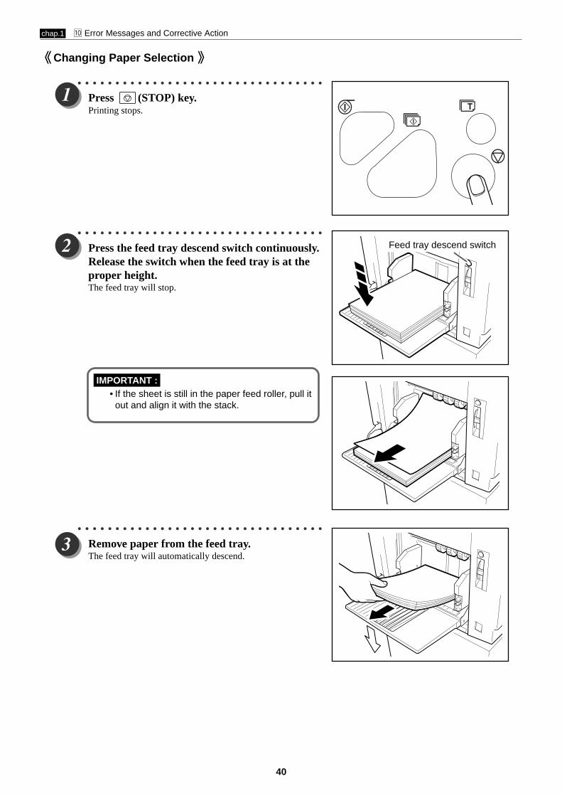
Changing Paper Selection
○ ○ ○ ○ ○ ○ ○ ○ ○ ○ ○ ○ ○ ○ ○ ○ ○ ○ ○ ○ ○ ○ ○ ○ ○ ○ ○ ○ ○ ○ ○ ○ ○
Press (STOP) key.Printing stops.
○ ○ ○ ○ ○ ○ ○ ○ ○ ○ ○ ○ ○ ○ ○ ○ ○ ○ ○ ○ ○ ○ ○ ○ ○ ○ ○ ○ ○ ○ ○ ○ ○
Press the feed tray descend switch continuously.Release the switch when the feed tray is at theproper height.The feed tray will stop.
IMPORTANT :• If the sheet is still in the paper feed roller, pull it
out and align it with the stack.
○ ○ ○ ○ ○ ○ ○ ○ ○ ○ ○ ○ ○ ○ ○ ○ ○ ○ ○ ○ ○ ○ ○ ○ ○ ○ ○ ○ ○ ○ ○ ○ ○
Remove paper from the feed tray.The feed tray will automatically descend.
Feed tray descend switch
chap.1 ⁄0 Error Messages and Corrective Action
41
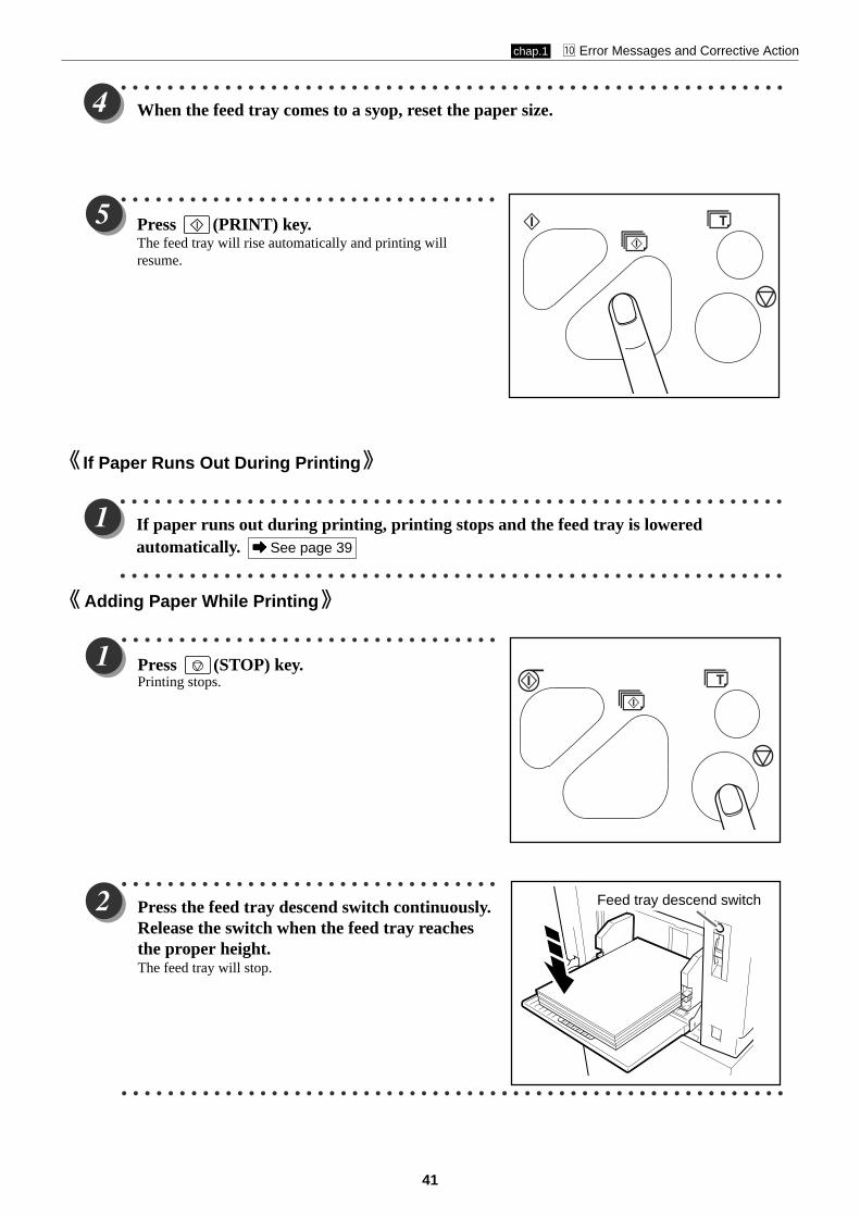
If Paper Runs Out During Printing
○ ○ ○ ○ ○ ○ ○ ○ ○ ○ ○ ○ ○ ○ ○ ○ ○ ○ ○ ○ ○ ○ ○ ○ ○ ○ ○ ○ ○ ○ ○ ○ ○ ○ ○ ○ ○ ○ ○ ○ ○ ○ ○ ○ ○ ○ ○ ○ ○ ○ ○ ○ ○ ○ ○ ○ ○ ○
If paper runs out during printing, printing stops and the feed tray is loweredautomatically. a a a a a See page 39
○ ○ ○ ○ ○ ○ ○ ○ ○ ○ ○ ○ ○ ○ ○ ○ ○ ○ ○ ○ ○ ○ ○ ○ ○ ○ ○ ○ ○ ○ ○ ○ ○ ○ ○ ○ ○ ○ ○ ○ ○ ○ ○ ○ ○ ○ ○ ○ ○ ○ ○ ○ ○ ○ ○ ○ ○ ○
○ ○ ○ ○ ○ ○ ○ ○ ○ ○ ○ ○ ○ ○ ○ ○ ○ ○ ○ ○ ○ ○ ○ ○ ○ ○ ○ ○ ○ ○ ○ ○ ○ ○ ○ ○ ○ ○ ○ ○ ○ ○ ○ ○ ○ ○ ○ ○ ○ ○ ○ ○ ○ ○ ○ ○ ○ ○
When the feed tray comes to a syop, reset the paper size.
○ ○ ○ ○ ○ ○ ○ ○ ○ ○ ○ ○ ○ ○ ○ ○ ○ ○ ○ ○ ○ ○ ○ ○ ○ ○ ○ ○ ○ ○ ○ ○ ○
Press (PRINT) key.The feed tray will rise automatically and printing willresume.
Adding Paper While Printing
○ ○ ○ ○ ○ ○ ○ ○ ○ ○ ○ ○ ○ ○ ○ ○ ○ ○ ○ ○ ○ ○ ○ ○ ○ ○ ○ ○ ○ ○ ○ ○ ○
Press (STOP) key.Printing stops.
○ ○ ○ ○ ○ ○ ○ ○ ○ ○ ○ ○ ○ ○ ○ ○ ○ ○ ○ ○ ○ ○ ○ ○ ○ ○ ○ ○ ○ ○ ○ ○ ○
Press the feed tray descend switch continuously.Release the switch when the feed tray reachesthe proper height.The feed tray will stop.
○ ○ ○ ○ ○ ○ ○ ○ ○ ○ ○ ○ ○ ○ ○ ○ ○ ○ ○ ○ ○ ○ ○ ○ ○ ○ ○ ○ ○ ○ ○ ○ ○ ○ ○ ○ ○ ○ ○ ○ ○ ○ ○ ○ ○ ○ ○ ○ ○ ○ ○ ○ ○ ○ ○ ○ ○ ○
Feed tray descend switch
chap.1 ⁄0 Error Messages and Corrective Action
42
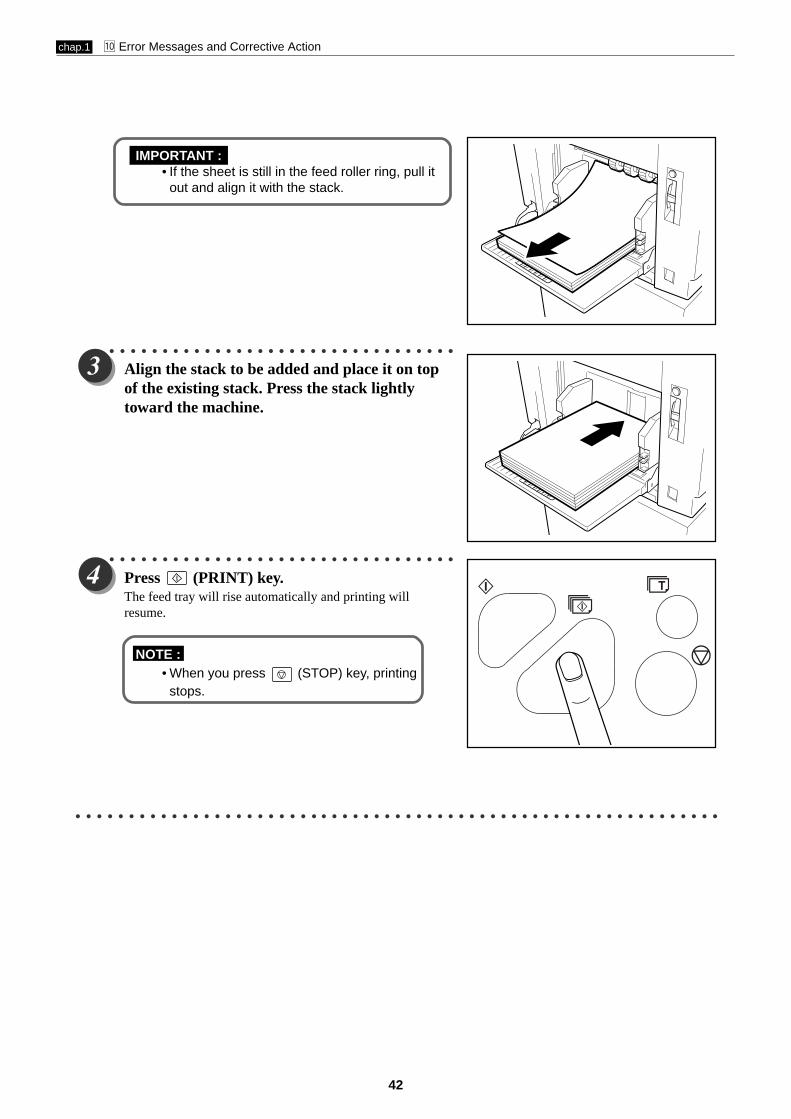
IMPORTANT :• If the sheet is still in the feed roller ring, pull it
out and align it with the stack.
○ ○ ○ ○ ○ ○ ○ ○ ○ ○ ○ ○ ○ ○ ○ ○ ○ ○ ○ ○ ○ ○ ○ ○ ○ ○ ○ ○ ○ ○ ○ ○ ○
Align the stack to be added and place it on topof the existing stack. Press the stack lightlytoward the machine.
○ ○ ○ ○ ○ ○ ○ ○ ○ ○ ○ ○ ○ ○ ○ ○ ○ ○ ○ ○ ○ ○ ○ ○ ○ ○ ○ ○ ○ ○ ○ ○ ○
Press (PRINT) key.The feed tray will rise automatically and printing willresume.
NOTE :• When you press (STOP) key, printing
stops.
○ ○ ○ ○ ○ ○ ○ ○ ○ ○ ○ ○ ○ ○ ○ ○ ○ ○ ○ ○ ○ ○ ○ ○ ○ ○ ○ ○ ○ ○ ○ ○ ○ ○ ○ ○ ○ ○ ○ ○ ○ ○ ○ ○ ○ ○ ○ ○ ○ ○ ○ ○ ○ ○ ○ ○ ○ ○ ○ ○ ○
JOG switch (Drum rotator switch)
chap.1 ⁄0 Error Messages and Corrective Action
43
○ ○ ○ ○ ○ ○ ○ ○ ○ ○ ○ ○ ○ ○ ○ ○ ○ ○ ○ ○ ○ ○ ○ ○ ○ ○ ○ ○ ○ ○ ○ ○ ○
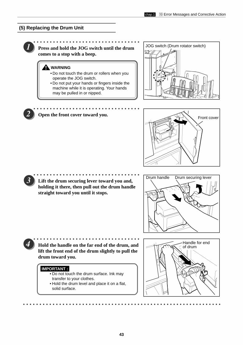
Press and hold the JOG switch until the drumcomes to a stop with a beep.
WARNING• Do not touch the drum or rollers when you
operate the JOG switch.• Do not put your hands or fingers inside the
machine while it is operating. Your handsmay be pulled in or nipped.
○ ○ ○ ○ ○ ○ ○ ○ ○ ○ ○ ○ ○ ○ ○ ○ ○ ○ ○ ○ ○ ○ ○ ○ ○ ○ ○ ○ ○ ○ ○ ○ ○
Open the front cover toward you.
○ ○ ○ ○ ○ ○ ○ ○ ○ ○ ○ ○ ○ ○ ○ ○ ○ ○ ○ ○ ○ ○ ○ ○ ○ ○ ○ ○ ○ ○ ○ ○ ○
Lift the drum securing lever toward you and,holding it there, then pull out the drum handlestraight toward you until it stops.
○ ○ ○ ○ ○ ○ ○ ○ ○ ○ ○ ○ ○ ○ ○ ○ ○ ○ ○ ○ ○ ○ ○ ○ ○ ○ ○ ○ ○ ○ ○ ○ ○
Hold the handle on the far end of the drum, andlift the front end of the drum slightly to pull thedrum toward you.
IMPORTANT :• Do not touch the drum surface. Ink may
transfer to your clothes.• Hold the drum level and place it on a flat,
solid surface.
○ ○ ○ ○ ○ ○ ○ ○ ○ ○ ○ ○ ○ ○ ○ ○ ○ ○ ○ ○ ○ ○ ○ ○ ○ ○ ○ ○ ○ ○ ○ ○ ○ ○ ○ ○ ○ ○ ○ ○ ○ ○ ○ ○ ○ ○ ○ ○ ○ ○ ○ ○ ○ ○ ○ ○ ○ ○ ○ ○ ○
(5) Replacing the Drum Unit
Front cover
Drum securing leverDrum handle
Handle for endof drum

chap.1 ⁄0 Error Messages and Corrective Action
44
Installing the Drum Unit
○ ○ ○ ○ ○ ○ ○ ○ ○ ○ ○ ○ ○ ○ ○ ○ ○ ○ ○ ○ ○ ○ ○ ○ ○ ○ ○ ○ ○ ○ ○ ○ ○
Hold the drum level and place the drum guideroller onto the rail in the machine.
○ ○ ○ ○ ○ ○ ○ ○ ○ ○ ○ ○ ○ ○ ○ ○ ○ ○ ○ ○ ○ ○ ○ ○ ○ ○ ○ ○ ○ ○ ○ ○ ○
Release the handle at the far end of the drumand press the drum in about 10cm while liftingup the front end slightly.
○ ○ ○ ○ ○ ○ ○ ○ ○ ○ ○ ○ ○ ○ ○ ○ ○ ○ ○ ○ ○ ○ ○ ○ ○ ○ ○ ○ ○ ○ ○ ○ ○ ○ ○ ○ ○ ○ ○ ○ ○ ○ ○ ○ ○ ○ ○ ○ ○ ○ ○ ○ ○ ○ ○ ○ ○ ○
Hold the drum level and press it in gently until it comes to a stop.
○ ○ ○ ○ ○ ○ ○ ○ ○ ○ ○ ○ ○ ○ ○ ○ ○ ○ ○ ○ ○ ○ ○ ○ ○ ○ ○ ○ ○ ○ ○ ○ ○
Lift the drum securing lever toward you whilepressing the drum in.
○ ○ ○ ○ ○ ○ ○ ○ ○ ○ ○ ○ ○ ○ ○ ○ ○ ○ ○ ○ ○ ○ ○ ○ ○ ○ ○ ○ ○ ○ ○ ○ ○
Lower the lever.
○ ○ ○ ○ ○ ○ ○ ○ ○ ○ ○ ○ ○ ○ ○ ○ ○ ○ ○ ○ ○ ○ ○ ○ ○ ○ ○ ○ ○ ○ ○ ○ ○ ○ ○ ○ ○ ○ ○ ○ ○ ○ ○ ○ ○ ○ ○ ○ ○ ○ ○ ○ ○ ○ ○ ○ ○ ○
Close the front cover.
○ ○ ○ ○ ○ ○ ○ ○ ○ ○ ○ ○ ○ ○ ○ ○ ○ ○ ○ ○ ○ ○ ○ ○ ○ ○ ○ ○ ○ ○ ○ ○ ○ ○ ○ ○ ○ ○ ○ ○ ○ ○ ○ ○ ○ ○ ○ ○ ○ ○ ○ ○ ○ ○ ○ ○ ○ ○ ○ ○ ○
Roller
Rail
Lever
Lever

JOG switch (Drum rotator switch)
chap.1 ⁄0 Error Messages and Corrective Action
45
If the message "PAPER LEFT JAM" is indicated in the LCD,
check the feeder side and remove the jammed paper by
following the procedure below.
○ ○ ○ ○ ○ ○ ○ ○ ○ ○ ○ ○ ○ ○ ○ ○ ○ ○ ○ ○ ○ ○ ○ ○ ○ ○ ○ ○ ○ ○ ○ ○ ○
Switch to lower the feed tray slightly.
The feed tray is lowered for the time that theswitch is pressed.
○ ○ ○ ○ ○ ○ ○ ○ ○ ○ ○ ○ ○ ○ ○ ○ ○ ○ ○ ○ ○ ○ ○ ○ ○ ○ ○ ○ ○ ○ ○ ○ ○
Pull out the jammed paper as shown in thediagram.
○ ○ ○ ○ ○ ○ ○ ○ ○ ○ ○ ○ ○ ○ ○ ○ ○ ○ ○ ○ ○ ○ ○ ○ ○ ○ ○ ○ ○ ○ ○ ○ ○
Press and hold the JOG switch until the drumcomes to a stop with a beep.
WARNING• Do not touch the drum or rollers when you
operate the JOG switch.• Do not put your hands or fingers inside the
machine while it is operating. Your handsmay be pulled in or nipped.
○ ○ ○ ○ ○ ○ ○ ○ ○ ○ ○ ○ ○ ○ ○ ○ ○ ○ ○ ○ ○ ○ ○ ○ ○ ○ ○ ○ ○ ○ ○ ○ ○ ○ ○ ○ ○ ○ ○ ○ ○ ○ ○ ○ ○ ○ ○ ○ ○ ○ ○ ○ ○ ○ ○ ○ ○ ○ ○ ○ ○
(6) Paper Jam (Feeder Side)
PAPER LEFT JAM
Feed tray descend switch
Master ejection boxrelease lever
chap.1 ⁄0 Error Messages and Corrective Action
46
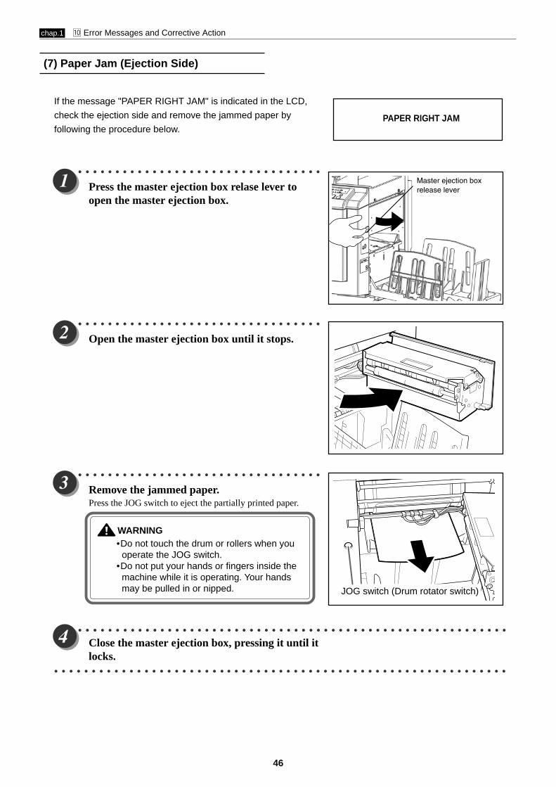
If the message "PAPER RIGHT JAM" is indicated in the LCD,
check the ejection side and remove the jammed paper by
following the procedure below.
○ ○ ○ ○ ○ ○ ○ ○ ○ ○ ○ ○ ○ ○ ○ ○ ○ ○ ○ ○ ○ ○ ○ ○ ○ ○ ○ ○ ○ ○ ○ ○ ○
Press the master ejection box relase lever toopen the master ejection box.
○ ○ ○ ○ ○ ○ ○ ○ ○ ○ ○ ○ ○ ○ ○ ○ ○ ○ ○ ○ ○ ○ ○ ○ ○ ○ ○ ○ ○ ○ ○ ○ ○
Open the master ejection box until it stops.
○ ○ ○ ○ ○ ○ ○ ○ ○ ○ ○ ○ ○ ○ ○ ○ ○ ○ ○ ○ ○ ○ ○ ○ ○ ○ ○ ○ ○ ○ ○ ○ ○
Remove the jammed paper.Press the JOG switch to eject the partially printed paper.
WARNING•Do not touch the drum or rollers when you
operate the JOG switch.•Do not put your hands or fingers inside the
machine while it is operating. Your handsmay be pulled in or nipped.
○ ○ ○ ○ ○ ○ ○ ○ ○ ○ ○ ○ ○ ○ ○ ○ ○ ○ ○ ○ ○ ○ ○ ○ ○ ○ ○ ○ ○ ○ ○ ○ ○ ○ ○ ○ ○ ○ ○ ○ ○ ○ ○ ○ ○ ○ ○ ○ ○ ○ ○ ○ ○ ○ ○ ○ ○ ○
Close the master ejection box, pressing it until itlocks.
○ ○ ○ ○ ○ ○ ○ ○ ○ ○ ○ ○ ○ ○ ○ ○ ○ ○ ○ ○ ○ ○ ○ ○ ○ ○ ○ ○ ○ ○ ○ ○ ○ ○ ○ ○ ○ ○ ○ ○ ○ ○ ○ ○ ○ ○ ○ ○ ○ ○ ○ ○ ○ ○ ○ ○ ○ ○ ○ ○ ○
(7) Paper Jam (Ejection Side)
PAPER RIGHT JAM
JOG switch (Drum rotator switch)

Master ejection box release lever
chap.1 ⁄0 Error Messages and Corrective Action
47
Paper Adhering to Drum
○ ○ ○ ○ ○ ○ ○ ○ ○ ○ ○ ○ ○ ○ ○ ○ ○ ○ ○ ○ ○ ○ ○ ○ ○ ○ ○ ○ ○ ○ ○ ○ ○
Press the master ejection box relase lever toopen the master ejection box.
○ ○ ○ ○ ○ ○ ○ ○ ○ ○ ○ ○ ○ ○ ○ ○ ○ ○ ○ ○ ○ ○ ○ ○ ○ ○ ○ ○ ○ ○ ○ ○ ○
Open the master ejection box until it stops.
○ ○ ○ ○ ○ ○ ○ ○ ○ ○ ○ ○ ○ ○ ○ ○ ○ ○ ○ ○ ○ ○ ○ ○ ○ ○ ○ ○ ○ ○ ○ ○ ○
Press the JOG switch to find the edge of thepaper, then stop the drum at the position shownin the diagram.
WARNING• Do not touch the drum or rollers when you
operate the JOG switch.• Do not put your hands inside the machine
while it is operating. Your hands may bepulled in or nipped.
○ ○ ○ ○ ○ ○ ○ ○ ○ ○ ○ ○ ○ ○ ○ ○ ○ ○ ○ ○ ○ ○ ○ ○ ○ ○ ○ ○ ○ ○ ○ ○ ○
Peel off the edge of the paper from the drum.
○ ○ ○ ○ ○ ○ ○ ○ ○ ○ ○ ○ ○ ○ ○ ○ ○ ○ ○ ○ ○ ○ ○ ○ ○ ○ ○ ○ ○ ○ ○ ○ ○ ○ ○ ○ ○ ○ ○ ○ ○ ○ ○ ○ ○ ○ ○ ○ ○ ○ ○ ○ ○ ○ ○ ○ ○ ○ ○ ○ ○
Paper edge

chap.1 ⁄0 Error Messages and Corrective Action
48
○ ○ ○ ○ ○ ○ ○ ○ ○ ○ ○ ○ ○ ○ ○ ○ ○ ○ ○ ○ ○ ○ ○ ○ ○ ○ ○ ○ ○ ○ ○ ○ ○
Pull the paper toward the ejection side whilepressing the JOG switch to peel the paper off.
IMPORTANT :• Make sure that the peeled paper does not
stick to your clothing.
○ ○ ○ ○ ○ ○ ○ ○ ○ ○ ○ ○ ○ ○ ○ ○ ○ ○ ○ ○ ○ ○ ○ ○ ○ ○ ○ ○ ○ ○ ○ ○ ○
Hold the JOG switch down until the drumcomes to a stop with a beep.
○ ○ ○ ○ ○ ○ ○ ○ ○ ○ ○ ○ ○ ○ ○ ○ ○ ○ ○ ○ ○ ○ ○ ○ ○ ○ ○ ○ ○ ○ ○ ○ ○
Close the master ejection box, pressing it until itlocks.
○ ○ ○ ○ ○ ○ ○ ○ ○ ○ ○ ○ ○ ○ ○ ○ ○ ○ ○ ○ ○ ○ ○ ○ ○ ○ ○ ○ ○ ○ ○ ○ ○ ○ ○ ○ ○ ○ ○ ○ ○ ○ ○ ○ ○ ○ ○ ○ ○ ○ ○ ○ ○ ○ ○ ○ ○ ○
Make another master.
○ ○ ○ ○ ○ ○ ○ ○ ○ ○ ○ ○ ○ ○ ○ ○ ○ ○ ○ ○ ○ ○ ○ ○ ○ ○ ○ ○ ○ ○ ○ ○ ○ ○ ○ ○ ○ ○ ○ ○ ○ ○ ○ ○ ○ ○ ○ ○ ○ ○ ○ ○ ○ ○ ○ ○ ○ ○ ○ ○ ○
JOG switch (Drum rotator switch)
JOG switch(Drum rotator switch)

Master ejection boxrelease lever
chap.1 ⁄0 Error Messages and Corrective Action
49
○ ○ ○ ○ ○ ○ ○ ○ ○ ○ ○ ○ ○ ○ ○ ○ ○ ○ ○ ○ ○ ○ ○ ○ ○ ○ ○ ○ ○ ○ ○ ○ ○
Press the master ejection box release lever toopen the master ejection box.
○ ○ ○ ○ ○ ○ ○ ○ ○ ○ ○ ○ ○ ○ ○ ○ ○ ○ ○ ○ ○ ○ ○ ○ ○ ○ ○ ○ ○ ○ ○ ○ ○
Open the master ejection box until it stops.
○ ○ ○ ○ ○ ○ ○ ○ ○ ○ ○ ○ ○ ○ ○ ○ ○ ○ ○ ○ ○ ○ ○ ○ ○ ○ ○ ○ ○ ○ ○ ○ ○
Press the JOG switch to find the edge of thepaper, then stop the drum at the position shownin the diagram.
WARNING•Do not touch the drum or rollers when you
operate the JOG switch.•Do not put your hands inside the machine
while it is operating. Your hands may bepulled in or nipped.
○ ○ ○ ○ ○ ○ ○ ○ ○ ○ ○ ○ ○ ○ ○ ○ ○ ○ ○ ○ ○ ○ ○ ○ ○ ○ ○ ○ ○ ○ ○ ○ ○
Lift the lever toward you.The master clamp opens and the edge of the master will bereleased from the clamp. If the master is stuck, release itmanually.
○ ○ ○ ○ ○ ○ ○ ○ ○ ○ ○ ○ ○ ○ ○ ○ ○ ○ ○ ○ ○ ○ ○ ○ ○ ○ ○ ○ ○ ○ ○ ○ ○ ○ ○ ○ ○ ○ ○ ○ ○ ○ ○ ○ ○ ○ ○ ○ ○ ○ ○ ○ ○ ○ ○ ○ ○ ○ ○ ○ ○
(8) Master is Not Ejected
Master
Lever
Master clamp

chap.1 ⁄0 Error Messages and Corrective Action
50
○ ○ ○ ○ ○ ○ ○ ○ ○ ○ ○ ○ ○ ○ ○ ○ ○ ○ ○ ○ ○ ○ ○ ○ ○ ○ ○ ○ ○ ○ ○ ○ ○ ○ ○ ○ ○ ○ ○ ○ ○ ○ ○ ○ ○ ○ ○ ○ ○ ○ ○ ○ ○ ○ ○ ○ ○ ○
Return the lever.
○ ○ ○ ○ ○ ○ ○ ○ ○ ○ ○ ○ ○ ○ ○ ○ ○ ○ ○ ○ ○ ○ ○ ○ ○ ○ ○ ○ ○ ○ ○ ○ ○
Pull the front end of the master toward you andpress the JOG switch intermittently.Hold the switch down until the master peels off.
IMPORTANT :• Discard the old master, making sure that it
does not touch your clothing.
○ ○ ○ ○ ○ ○ ○ ○ ○ ○ ○ ○ ○ ○ ○ ○ ○ ○ ○ ○ ○ ○ ○ ○ ○ ○ ○ ○ ○ ○ ○ ○ ○ ○ ○ ○ ○ ○ ○ ○ ○ ○ ○ ○ ○ ○ ○ ○ ○ ○ ○ ○ ○ ○ ○ ○ ○ ○
Hold the JOG switch down until the drum comes to a stop with a beep.
○ ○ ○ ○ ○ ○ ○ ○ ○ ○ ○ ○ ○ ○ ○ ○ ○ ○ ○ ○ ○ ○ ○ ○ ○ ○ ○ ○ ○ ○ ○ ○ ○
Close the master ejection box, pressing it until itlocks.
○ ○ ○ ○ ○ ○ ○ ○ ○ ○ ○ ○ ○ ○ ○ ○ ○ ○ ○ ○ ○ ○ ○ ○ ○ ○ ○ ○ ○ ○ ○ ○ ○
Press (STOP) key.The message is deleted.
○ ○ ○ ○ ○ ○ ○ ○ ○ ○ ○ ○ ○ ○ ○ ○ ○ ○ ○ ○ ○ ○ ○ ○ ○ ○ ○ ○ ○ ○ ○ ○ ○ ○ ○ ○ ○ ○ ○ ○ ○ ○ ○ ○ ○ ○ ○ ○ ○ ○ ○ ○ ○ ○ ○ ○ ○ ○
Make another master.
○ ○ ○ ○ ○ ○ ○ ○ ○ ○ ○ ○ ○ ○ ○ ○ ○ ○ ○ ○ ○ ○ ○ ○ ○ ○ ○ ○ ○ ○ ○ ○ ○ ○ ○ ○ ○ ○ ○ ○ ○ ○ ○ ○ ○ ○ ○ ○ ○ ○ ○ ○ ○ ○ ○ ○ ○ ○ ○ ○ ○
JOG switch(Drum rotator switch)
chap.1 ⁄0 Error Messages and Corrective Action
51
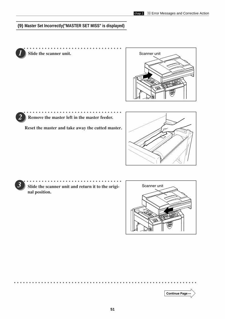
(9) Master Set Incorrectly("MASTER SET MISS" is displayed)
○ ○ ○ ○ ○ ○ ○ ○ ○ ○ ○ ○ ○ ○ ○ ○ ○ ○ ○ ○ ○ ○ ○ ○ ○ ○ ○ ○ ○ ○ ○ ○ ○
Slide the scanner unit.
○ ○ ○ ○ ○ ○ ○ ○ ○ ○ ○ ○ ○ ○ ○ ○ ○ ○ ○ ○ ○ ○ ○ ○ ○ ○ ○ ○ ○ ○ ○ ○ ○
○ ○ ○ ○ ○ ○ ○ ○ ○ ○ ○ ○ ○ ○ ○ ○ ○ ○ ○ ○ ○ ○ ○ ○ ○ ○ ○ ○ ○ ○ ○ ○ ○
Remove the master left in the master feeder.
○ ○ ○ ○ ○ ○ ○ ○ ○ ○ ○ ○ ○ ○ ○ ○ ○ ○ ○ ○ ○ ○ ○ ○ ○ ○ ○ ○ ○ ○ ○ ○ ○ ○ ○ ○ ○ ○ ○ ○ ○ ○ ○ ○ ○ ○ ○ ○ ○ ○ ○ ○ ○ ○ ○ ○ ○ ○ ○ ○ ○
Scanner unit
Continue Page • ••
Reset the master and take away the cutted master.
Scanner unitSlide the scanner unit and return it to the origi-nal position.

chap.1 ⁄0 Error Messages and Corrective Action
52
○ ○ ○ ○ ○ ○ ○ ○ ○ ○ ○ ○ ○ ○ ○ ○ ○ ○ ○ ○ ○ ○ ○ ○ ○ ○ ○ ○ ○ ○ ○ ○ ○
Check that the error message is deleted.
○ ○ ○ ○ ○ ○ ○ ○ ○ ○ ○ ○ ○ ○ ○ ○ ○ ○ ○ ○ ○ ○ ○ ○ ○ ○ ○ ○ ○ ○ ○ ○ ○ ○ ○ ○ ○ ○ ○ ○ ○ ○ ○ ○ ○ ○ ○ ○ ○ ○ ○ ○ ○ ○ ○ ○ ○ ○
Make a new master and start printing.
• The message “PLS MASTER MAKING” is displayed on the LCD panel when (PRINT) keyis pressed without mastermaking being carried out.
○ ○ ○ ○ ○ ○ ○ ○ ○ ○ ○ ○ ○ ○ ○ ○ ○ ○ ○ ○ ○ ○ ○ ○ ○ ○ ○ ○ ○ ○ ○ ○ ○ ○ ○ ○ ○ ○ ○ ○ ○ ○ ○ ○ ○ ○ ○ ○ ○ ○ ○ ○ ○ ○ ○ ○ ○ ○ ○ ○ ○
IMPORTANT

53
Chapter 2 Description of the Operation
z Scanner Section...........................................................551. Description...............................................................552. Sequence of Operation...........................................56
(1) Sequence of the Scanner Operation..................56(2) Sequence of the Scanner Operation (ADF).......56
3. Function of Parts and Circuit.................................57(1) Home Position Sensors.......................................57(2) CCD / Lamps......................................................58
x Mastermaking / Master Feed / Ejection Section........59Mastermaking / Master Feed Section .....................591. Description...............................................................592. Sequence of Operation...........................................60
Operation when the master set switch is turned on.............................................60
Mastermaking and Master Feeding.......................623. Function of Parts ....................................................65
Thermal Head...........................................................65End Mark Sensor1...................................................68
1. Master Setting Error Detection......................692. Master End Detection......................................69
Cutter Unit...............................................................72Master Feed Clutch (Electromagnetic clutch)........73
Master Ejection Section..............................................741. Description...............................................................742. Circuit.......................................................................743. Function of Parts ....................................................75
(1) Master Ejection Sensor......................................751. Plate Ejection Error Detection........................752. Rotation Control of the Roll-up Motor............75
Master Clamp opening/Closing Section....................761. Description...............................................................762. Operation of Master Clamp Open / Close Lever ........77
(1) Structure.............................................................77(2) Master Attachment / Detachment Operation...78(3) Clamp Opening / Closing
Lever Position (A / B / C Mode).........................793. Function of Parts ....................................................80
(1) A / B / C Mode Sensor.........................................804. Returning Operation Flowchart
When the Power is Cut Off Accidentally.............. .81
c Paper Feed Section......................................................821. Description...............................................................822. Operation................................................................. 83
(1) Rotation of the Paper Feed Roller and Timing Roller.....................................................83
(2) Paper Feed Roller Drive.....................................84(3) Driving of the Timing Roller..............................85(4) Escape the Guide Roller ................................... 86
(5) Paper Feed Length.............................................87
3. Function of Parts.....................................................88(1) Printing Position Adjustment Mechanism........88(2) Signal Lever........................................................90(3) Feed Tray (Elevator) Upper Limit Sensor........ 91(4) Feed Tray (Elevator) Lower Limit Switch........ 92(5) Paper Sensor.......................................................93(6) Paper Feed Length Sensor.................................94
End Mark Sensor2...................................................71

54
2
v Drum Driving Section..................................................951. Description...............................................................952. Function of Parts ....................................................96
(1) Home Position / Jam Detection Position Sensor..................................................96
(2) Master Attachment / Detachment Position Sensor..................................................97
(3) Jog Switch(Drum Rotator Switch).....................98(4) Control of the Main Motor.................................99
1. Rotation Speed Control by Encoder Sensor...100
b Press Section...............................................................1011. Description...............................................................101
(1) Press Roller Timing & Printing Area................1012. Function of Parts .................................................. 103
(1) Press Roller (P Roll) Sensor............................. 103
n Paper Ejection Section..............................................1041. Description.............................................................1042. Function of Parts ..................................................105
(1) Paper Stripper Finger......................................105(2) Jam Sensor ......................................................106
1. Paper Jam Detection Timing........................107(3) Paper aligning mechanism..............................108
m Drum Section.............................................................1091. Description.............................................................1092. Circuit.....................................................................1103. Function of Part.....................................................111
(1) Ink Detection....................................................1111. LED Display and Output Signal on
the Ink Detection PCB Unit..........................1122. "EXCHANGE INK" Display Timing.............113
(2) Ink Pump..........................................................114(3) Drum Switch.....................................................115(4) Front Cover Open / Close Detection Switch....116

55
z Scanner Sectionchap.2
zScanner Section
1. DescriptionThe document is illuminated with the lamps, and the document reflection in proportion to the documentimage darkness is imaged on the CCDs through the mirror and lens. Then it is resoluted into picture elementsand converted photoelectrically.
• The optical system gose forward (to the left) or back ward with a stop position of Fixed document home position sensor(PS1).
Optical System Operation
24S068
• When ADF is attached, set the ADF Home Position Sensor (PS2) as the optical system stop position, andthen read the document darkness.
Optical System Operation (with ADF attached)
24S068A
Glass
Mirror
MirrorLens
Fixed document home position sensor(PS1)
CCD
LampADF
home position sensor(PS2)
ADFhome position sensor(PS2)
Glass
Fixed document home position sensor(PS1)
Mirror
Mirror CCDLens
Lamp
56
z Scanner Sectionchap.2
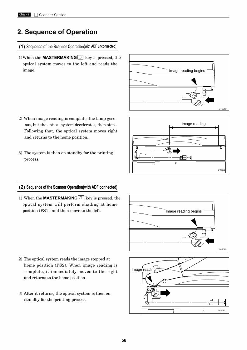
(1) Sequence of the Scanner Operation(with ADF unconnected)
2. Sequence of Operation
1)When the MASTERMAKING key is pressed, theoptical system moves to the left and reads theimage. Image reading begins
24S069
Image reading
24S070
(2) Sequence of the Scanner Operation(with ADF connected)
24S069
24S070
2) When image reading is complate, the lamp goseout, but the optical system decelerates, then stops.Following that, the optical system moves rightand returns to the home position.
3) The system is then on standby for the printingprocess.
1) When the MASTERMAKING key is pressed, theoptical system will perform shading at homeposition (PS1), and then move to the left.
3) After it returns, the optical system is then onstandby for the printing process.
2) The optical system reads the image stopped at home position (PS2). When image reading is complete, it immediately moves to the rightand returns to the home position.
Image reading begins
Image reading

57
z Scanner Sectionchap.2
3. Function of Parts and Circuit(1) Home Position Sensors
DescriptionPS1 detects the optical system home position when ADF is not used.PS2 detects the optical system home position when ADF is used.
Home position sensor (PS1)
Main PCB Unit
Red
Blue
J7-12123 -13
Yellow -14
3.3V5V
03.3V Photopass : 0V
Photointerrupting : 3.3V
Circuit
Operation
23S0214
Photointerrupting plate
Slider A
Fixed document home position sensor(PS1)
ADFhome position sensor(PS2)
Slider A
Photointerrupting plate Photointerrupting plate
Photointerrupting plate
A shading plate is attached on slider A of the optical system. The position where PS1 is shaded becomes theoptical system home position when ADF is not attached. The position where PS2 is shaded becomes the optical system home position when ADF is attached.
Home position sensor (PS2)
Main PCB Unit
Red
Blue
J12-14123 J7-15
Orange J7-16
3.3V5V
03.3V Photopass : 0V
Photointerrupting : 3.3V
• Standard (ADF not attached) • With ADF attached

58
z Scanner Sectionchap.2
(2) CCD / Lamp
DescriptionThe lamp illuminates the document and the reflected light is transmitted onto the CCDs.The CCDs outputthe image signals in level of voltage.
This machine adopts a xenon lamp which is lit quickly when turned on, and the quantity of light isstable.The lamp is lit when the the control signal CN1-1 for the lamp inverter unit is LOW (0V) .
The table below shows the specification for the CCD.
Circuit
• Lamp
• CCD
Specification
No. Item Specification
1 Optical signal storage time (SH cycle) 2.048 msec/line
2 Frequency 3.375MHz
3 The number of effective picture elements 3000 picture elements
4 Reading width(This is not the image width which can be processed.) 254mm
5 Reading density 11.8 dot/mm(300DPI)
J2-11
J2-26
J2-12
Yellow
Brown
J5-1
J5-12

59
x Mastermaking / Master Feed / Ejection Sectionchap.2
xMastermaking / Master Feed / Ejection Section
1. Description
Make the master clamp of the drum unit clamp the master top end, performing mastermaking on the masterwith the thermal head. (In this machine, the master on the drum is ejected at the same time when platemaking is performed.)The master is conveyed to the drum unit via the platen roller and sponge roller by driving of the steppingmotor, while it is being processed in the head section. Sponge roller is driven through the master feedingclutch (electromagnetic clutch), and controls the amount of master conveyed to the master clamp section ofthe drum unit with the master feeding clutch ON / OFF.The end-mark sensor1 starts to detect when the end mark (black) section printed on the end of the roll masteris conveyed. The indicator lights for "roll-master end" are lit on the control panel. The endmark sensor also detects whether the master is conveyed properly through the sensor.
Master feeding clutch
Sponge roller
End-mark sensor 1
Stepping motorRoll master
Platen roller
Thermal head
End-mark sensor 2
Mastermaking / Master Feed Section

60
x Mastermaking / Master Feed / Ejection Sectionchap.2
Operation when the master set switch is turned on(1) Pressing the master set switch turns on the master
feeding motor (PM2) and the master feeding clutch(CL1) to rotate the platen roller and the sponge roller.
(2) When the master is fed and the end mark sensor (PS3)detects the front end of the master, the master feedingclutch (CL1) is turned off.
(3)The master feeding motor (PM2) stops approx.3 seconds after the master set switch (SW1) is pressed.
(4) The cutter motor (M5) is turned on to move the cutterfrom the operation side to rear side while cutting themaster.
2. Sequence of Operation
61
x Mastermaking / Master Feed / Ejection Sectionchap.2
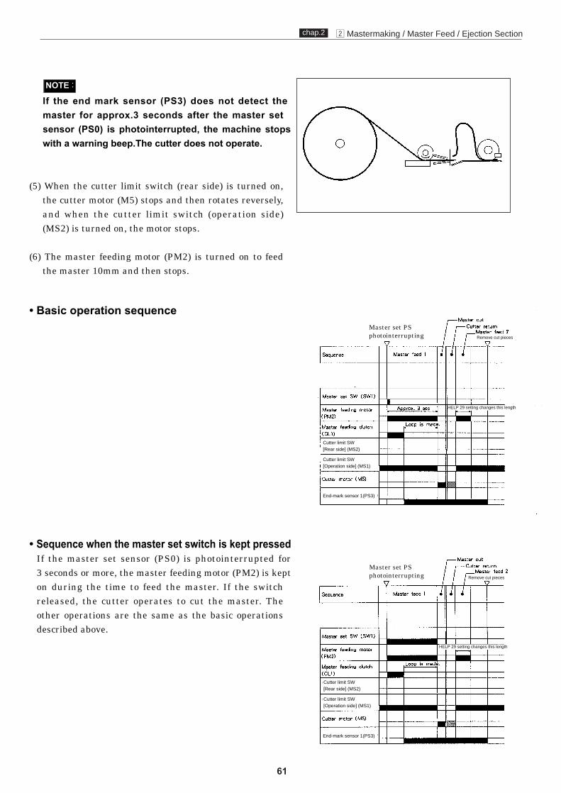
If the end mark sensor (PS3) does not detect the master for approx.3 seconds after the master set
(5) When the cutter limit switch (rear side) is turned on,the cutter motor (M5) stops and then rotates reversely,and when the cutter limit switch (operation side)(MS2) is turned on, the motor stops.
(6) The master feeding motor (PM2) is turned on to feedthe master 10mm and then stops.
NOTE :
• Sequence when the master set switch is kept pressed
on during the time to feed the master. If the switchreleased, the cutter operates to cut the master. Theother operations are the same as the basic operationsdescribed above.
• Basic operation sequence
Cutter limit SW[Rear side] (MS2)
Cutter limit SW[Operation side] (MS1)
Cutter limit SW[Rear side] (MS2)
Cutter limit SW[Operation side] (MS1)
Remove cut pieces
HELP 29 setting changes this length
Remove cut pieces
HELP 29 setting changes this length
End-mark sensor 1(PS3)
End-mark sensor 1(PS3)
sensor (PS0) is photointerrupted, the machine stops with a warning beep.The cutter does not operate.
Master set PSphotointerrupting
Master set PSphotointerrupting
If the master set sensor (PS0) is photointerrupted for 3 seconds or more, the master feeding motor (PM2) is kept

x Mastermaking / Master Feed / Ejection Sectionchap.2
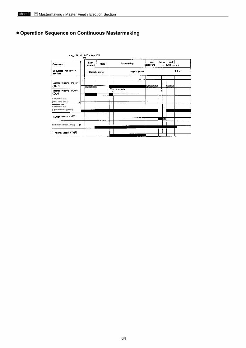
Mastermaking and Master feeding operations(1) Pressing "MASTERMAKING"key turns on the master
feeding motor (PM2) and master feeding clutch (CL1)to feed out the master.
(2) When the master is fed approx. 50mm, the masterfeeding motor (PM2) and master feeding clutch (CL1)stops.
(3) After the print section performs master detachment, thedrum moves to the master attachment position to openthe master clamp, and then the master feeding motor(PM2) and the master feeding clutch (CL1) are turned onand the thermal head (TH1) starts mastermaking.The master is fed toward the master clamp.
(4) When the master is fed approx. 20mm, the masterfeeding clutch (CL1) is turned off to stop the spongeroller.
62

(5) After the master clamp clamps the top end of the master, the drum rotates to wind the finished masteraround it. The sponge roller is not driven by the motorbecause the master feeding clutch (CL1) is turnedoff. The roller follows the movement of the masterpulled out by the drum.
(6) When mastermaking is completed, the thermal head(TH1) is turned off and the master feeding motor(PM2) feeds the master for the specified value (the totallength: 490mm) and then stops.
(7) The cutter cuts the master.
(8) The master feeding motor (PM2) is turned on to feedthe master approx. 10mm and then stops.
63
x Mastermaking / Master Feed / Ejection Sectionchap.2
x Mastermaking / Master Feed / Ejection Sectionchap.2
2Operation Sequence on Continuous Mastermaking
Cutter limit SW[Rear side] (MS2)
Cutter limit SW[Operation side] (MS1)
End-mark sensor 1(PS3)
64

65
x Mastermaking / Master Feed / Ejection Sectionchap.2
Thermal Head
DescriptionThe thermal elements are in alignment in the scanning direction, and are heated on the image section tomake holes on the master film.
Specifications
Circuit
3. Functions of Parts
No. Item DP-24S/DP-22S/DP-22L
1 Picture element density 300DPI (11.8 dot/mm)
2 Effective memory width 260.2 0.1mm
Main PCB unit
J3-1
-14
Main PCB unit
J4-1
-24
Ther
mal
hea
d
DP-M400/DP-M410/DP-M420
66
x Mastermaking / Master Feed / Ejection Sectionchap.2
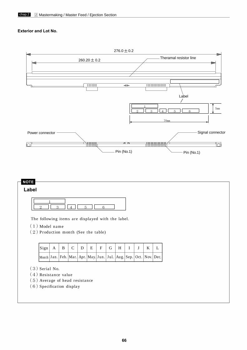
Exterior and Lot No.
Label
A B C D E F G H I J K L
Jan. Feb. Mar. Apr. May. Jun. Jul. Aug. Sep. Oct. Nov. Dec.
Sign
Month
NOTE
Label
Theramal resistor line
276.0 0.2
260.20 0.2
Signal connector
Pin (No.1)Pin (No.1)
Power connector
1
2 3 4 5 65mm
70mm
(1)
(2)
(3) 製品番号(4桁シリアル NO)
(4) 抵抗値ランク(弊社管理用)
(5)ヘッド平均抵抗値
(6)御社指定表示
The following items are displayed with the label.
Model nameProduction month (See the table)
Serial No.
Average of head resistanceSpecification display
1
2 3 4 5 6
Resistance value
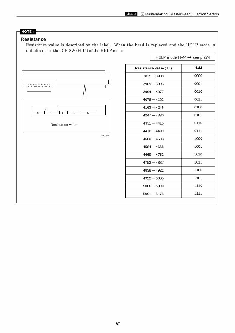
67
x Mastermaking / Master Feed / Ejection Sectionchap.2
NOTE :
Resistance value ( ) H-44
3825 3908 0000
3909 3993 0001
3994 4077 0010
4078 4162 0011
4163 4246 0100
4247 4330 0101
4331 4415 0110
4416 4499 0111
4500 4583 1000
4584 4668 1001
4669 4752 1010
4753 4837 1011
4838 4921 1100
4922 5005 1101
5006 5090 1110
5091 5175 1111
ResistanceResistance value is described on the label. When the head is replaced and the HELP mode is initialized, set the DIP-SW (H-44) of the HELP mode.
HELP mode H-44 \ see p.274
23S0326
Resistance value
1
2 3 4 5 6

68
x Mastermaking / Master Feed / Ejection Sectionchap.2
The end marks are located at a fixed distance relative to the master; as the master is being fed, the end-marksensor1 senses master condition and the end marks by means of intensity of reflected light.
The larger the reflection light amount is, the smaller the output voltage is. The smaller the light amount is,the larger the output voltage is.The value is checked with the HELP 13.
Main PCB Unit
End-mark sensor1 PCB unit
5V
5V
VR1
0
RedBlackBlue
RedBlackBlue
123
Circuit
Operation
3.3V
3.3VJ7-29
J7-27
J7-25
End-mark sensor 1
End-mark sensor 1
End mark
White level<=10, Black level>50
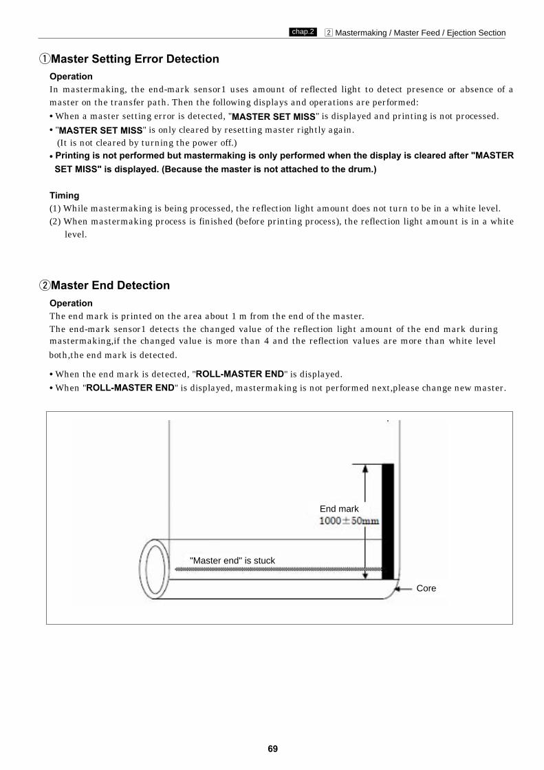
69
x Mastermaking / Master Feed / Ejection Sectionchap.2
qMaster Setting Error DetectionOperationIn mastermaking, the end-mark sensor1 uses amount of reflected light to detect presence or absence of a master on the transfer path. Then the following displays and operations are performed:
• When a master setting error is detected, "MASTER SET MISS" is displayed and printing is not processed.
• "MASTER SET MISS" is only cleared by resetting master rightly again.(It is not cleared by turning the power off.)
• Printing is not performed but mastermaking is only performed when the display is cleared after "MASTERSET MISS" is displayed. (Because the master is not attached to the drum.)
Timing(1) While mastermaking is being processed, the reflection light amount does not turn to be in a white level.(2) When mastermaking process is finished (before printing process), the reflection light amount is in a white
level.
wMaster End DetectionOperationThe end mark is printed on the area about 1 m from the end of the master.The end-mark sensor1 detects the changed value of the reflection light amount of the end mark during
• When the end mark is detected, "ROLL-MASTER END" is displayed.
• When "ROLL-MASTER END" is displayed, mastermaking is not performed next,please change new master.
"Master end" is stuck
End mark
Core
mastermaking,if the changed value is more than 4 and the reflection values are more than white level
both,the end mark is detected.

x Mastermaking / Master Feed / Ejection Sectionchap.2
TimingWhen it is considered that the end mark is read under the following conditions, the indicator lights for "roll-master end" are lit on the control panel.(1) While the master is rolling up to the drum during mastermaking, the following is checked.(2) The reflection light amount is read while the master passes.
(3) When the data meet the following requirements, the end mark is detected..
70
Maximum-Minimum > 4 and Minimum White level top limit.

71
x Mastermaking / Master Feed / Ejection Sectionchap.2
End-mark sensor 2
Main PCB Unit
End-mark sensor2 PCB unit
J7-30CN4-1-2-3 -26
-28
3.3V5V
5V
VR1
03.3V
RedLight green
Blue
Circuit
Operation
End-mark sensor 2
End mark label
• Master set miss : master is not fed rightly(the roll shaft sticked with End mark label is not rotated ) during mastermaking. Master roll reverses.
"MASTER SET MISS" is indicated.
The message could be cleared by master is set rightly again.
• Master set miss : When drum fail to clamp master correctly.When the clamp failed, master is cut. The master fed into cutter section is pulled back."MASTER SET MISS" is indicated.
* The cut master is left on the path. Make sure to remove it before setting a master.
The message could be cleared by master is set rightly again.

72
x Mastermaking / Master Feed / Ejection Sectionchap.2
Cutter Unit
Completed, the stepping motor for mastermaking and the drum stops temporarily, the cutter motor (MS) isturned on to drive the cutter and the master is cut.The home position for the cutter motor is at the cutter limit SW on the operation side (MS1). When the cuttermoves to turn on the cutter limit SW on the rear side (MS2), the cutter motor stops and then reversely rotatesto return to the home position.(The cutter motor can rotate normally and/or reversely.)
The cutter motor is at the home position when the cutter limit SW (MS1) is closed and the cutter limit SW(MS2) is opened. When cutting the master, the cutter motor rotates normally (CW) and moves from the operation side to the rear side. When the cutter limit SW (MS1) is opened and the cutter limit SW (MS2) isclosed after cutting is completed, the cutter motor stops and then rotates reversely (CCW) , and moves fromthe rear side to the operation side.
Normally(CW)
Cutter
Cutter limit switch(Rear side)
Cutter
Cutter limit switch(Operation side)
Cutter motor
Cutter
Cutter
Cutter limit switch(Rear side)
Cutter limit switch(Operation side)
Reversely(CCW)
Cutter motor
Circuit
Operation
CN4 45
419
CN2 420
MainJ1-20
3.3V
3.3V
3.3V
3.3V
J7-2
J7-1
J7-4
J7-3
Black
Red
Black
White
4
3

73
x Mastermaking / Master Feed / Ejection Sectionchap.2
Master Feeding Clutch(Electromagnetic clutch)
DescriptionSponge roller is attached to the bottom section of the master conveyance way of the master feeding unit, andis driven via the master feeding clutch (CL1) by the mastermaking motor. The rotation of sponge roller is controlled with the master feeding clutch ON / OFF.
Master feeding clutch (CL1)Circuit
J2-15
-16
Black
Black
Brown
Purple
Black
Black
1
2
1
2
Main PCB unit24VBrown
Purple
1. During mastermaking process the drum stops atthe master attachment position and the masterclamp is open (C mode) to turn the clutch on.Sponge roller is driven. The clutch is turned offwhen a certain amount of the master is fed.
2. The master clamp opens and closes, to clampthe master.
3. When the master is wound onto the drum, themaster feed clutch turns off, leaving spongeroller free to be turned by the master as it iswound off the drum.
C mode
C \\ B mode
Operation

74
x Mastermaking / Master Feed / Ejection Sectionchap.2
When the drum stops at the master detachment position and the master clamp which clamps the master tipend is opened (C mode), the pulling roller on the rolling section of the master ejection box pulls the master tipend into the box inside, and the master is rolled up to the core.If no core is installed, or when the master is fully wound onto the core, the core full switch (MS8) is mechanically actuated, and the message "EXCHG. EJECT-CORE" appears on the operation panel LCD panel.
2. Circuit
1. Description
Master Ejection Section
Pulling roller
Master detachmentposition
Master ejectionsensor photo-emitting PCB
Masterejection box
Core full switch
Core
Roll up motor
Master ejection sensorphoto-receiving PCB
JAM sensor photo-emitting PCB
23S0264
23S0311
PinkBlue
Blue
Blue
Blue
Pink
Green
Light blueRed
Black Green
Lightblue
OrangeOrange
Gray
Gray
Rollup motor
Jam sensorphoto-receing PCB
Jam sensorphoto-emitting PCB
Master ejection sensorphoto-emitting PCB
Core full switch
Master ejection sensorphoto-receing PCB
2
1
2
1
2
1
1
2
12
56
J7-18
-17
-19
-20
-23-24
-5-6
3.3V3.3V
3.3V
12
3
4
-21-22
3.3V
12
Main PCB unit
J2-8
-7

75
x Mastermaking / Master Feed / Ejection Sectionchap.2
2. Rotation Control of the Roll-up MotorIf the roll-up motor is kept rotating when the master tip end is pulled to the ejection box in the masterdetachment process, the drum is actuated by the master and the stop position slips. To prevent this, the roll-up motor is stopped when the master is detected by the master ejection sensor. (If the master is notdetected by the master ejection sensor, the Roll-up motor is stopped by the timer.)
(1) Master Ejection Sensor
DescriptionPhoto-emission from the master ejection sensor isreceived on the master ejection sensor, and thesensor detects with the photo strength whether themaster is pulled to the master ejection box. Photo-receiving amount is checked with theHELP5.
1. Master Ejection Error DetectionOperationWhile one mastermaking is being processed, the difference of photo-receiving amount is less than 8 by checkingwith the HELP5, which is determined as an master ejection error. The following display and operation areshown.2"MAST. EJECT ERROR" is displayed on the error display panel and printing is not processed.2"MAST. EJECT ERROR" is cleared with the ALL CLEAR key , STOP key or by performing
mastermaking / printing.2A master ejection error is not detected for one mastermaking soon after a master ejection error or master setting
error is detected.
¡If incorrect sensing occurs due to sensor malfunction, etc., HELP32can be used toprohibit master ejection error sensing.
IMPORTANT :
Smaller Larger
Photo-receiving amount
3. Function of Parts
HELP mode H-32 \ see p.265
HELP mode H-05 \ see p.239
HELP mode H-05 \ see p.239
2HELP mode H-05 value
00
TimingIf the variation in the amount of light received bythe master ejection sensor during the making of 1master is less than a certain level (8 in the HELP5display value), a master ejection error is deemed tohave occurred.
2HELP mode H-05 value
Value without master : the photo receiving amount ofthe master ejection sensor at the position where the firstpaper jam is detected after starting mastermaking.
00
Threshold value
Threshold value : Value without master + 8
Time
255
255
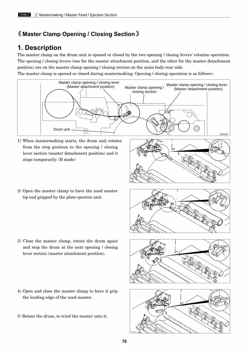
76
x Mastermaking / Master Feed / Ejection Sectionchap.2
1) When mastermaking starts, the drum unit rotatesfrom the stop position to the opening / closinglever section (master detachment position) and itstops temporarily. (B mode)
1. DescriptionThe master clamp on the drum unit is opened or closed by the two opening / closing levers' rotation operation.The opening / closing levers (one for the master attachment position, and the other for the master detachmentposition) are on the master clamp opening / closing section on the main body rear side.The master clamp is opened or closed during mastermaking. Opening / closing operation is as follows:-
5) Rotate the drum, to wind the master onto it.
4) Open and close the master clamp to have it gripthe leading edge of the used master.
3) Close the master clamp, rotate the drum againand stop the drum at the next opening / closinglever section (master attachment position).
2) Open the master clamp to have the used mastertip end gripped by the plate ejection unit.
Master Clamp Opening / Closing Section
Master clamp opening / closing lever(Master attachment position) Master clamp opening /
closing section
23S0265
Drum unit
Master clamp opening / closing lever(Master detachment position)
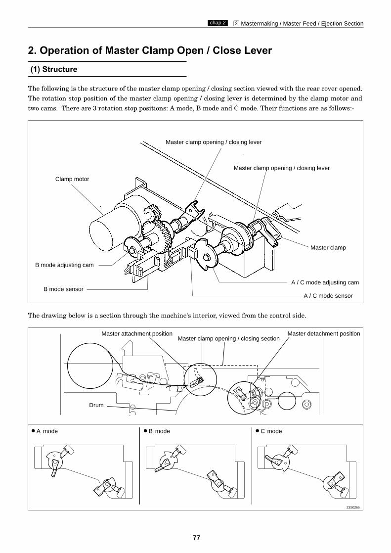
77
x Mastermaking / Master Feed / Ejection Sectionchap.2
The following is the structure of the master clamp opening / closing section viewed with the rear cover opened.The rotation stop position of the master clamp opening / closing lever is determined by the clamp motor andtwo cams. There are 3 rotation stop positions: A mode, B mode and C mode. Their functions are as follows:-
(1) Structure
2. Operation of Master Clamp Open / Close Lever
The drawing below is a section through the machine's interior, viewed from the control side.
Master clamp opening / closing lever
Master clamp opening / closing section
2A mode 2B mode 2C mode
Clamp motor
B mode adjusting cam
Master attachment position
Drum
Master detachment position
A / C mode adjusting camB mode sensor
A / C mode sensor
Master clamp opening / closing lever
Master clamp
23S0266
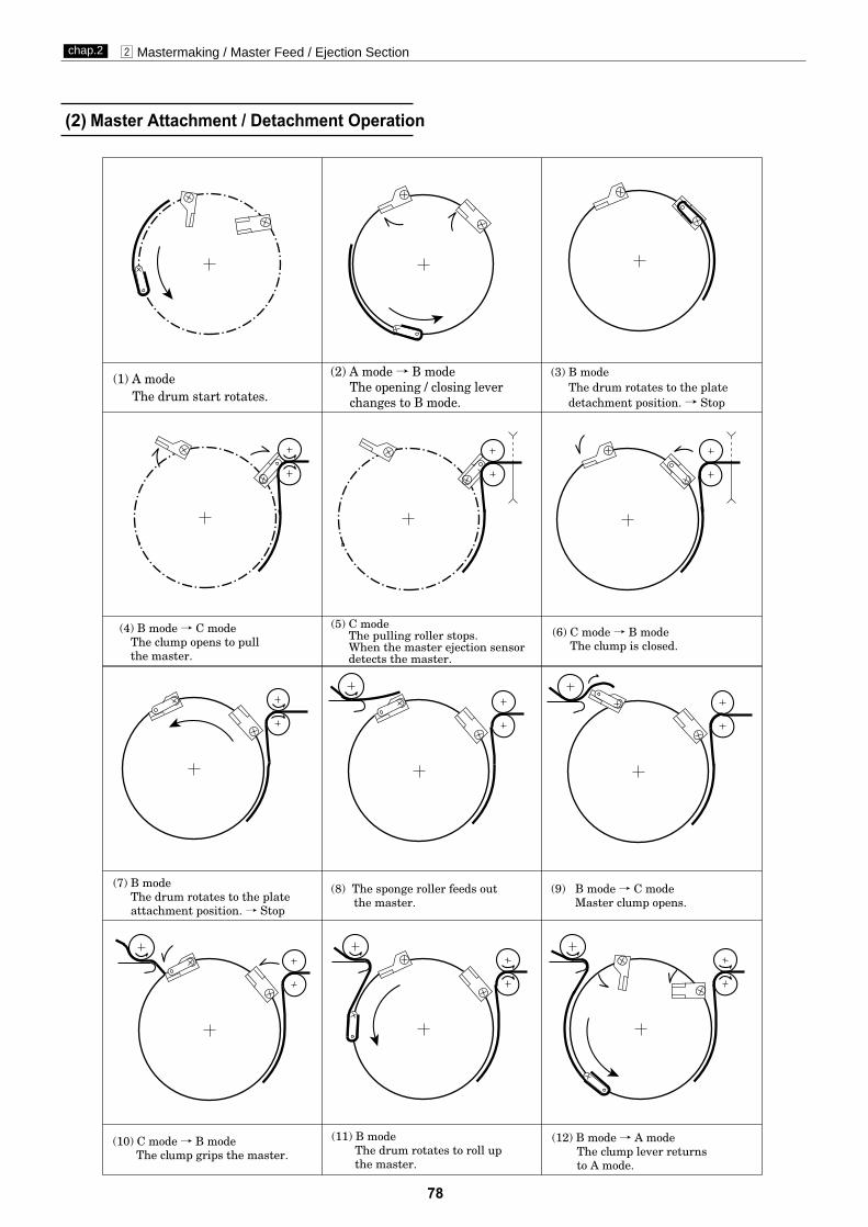
78
x Mastermaking / Master Feed / Ejection Sectionchap.2
(2) Master Attachment / Detachment Operation

79
x Mastermaking / Master Feed / Ejection Sectionchap.2
(3) Clamp Opening / Closing LeverPosition (A / B / C Mode)
Mode Photointerrupter stop position / state of sensor Functions
In the normal state or during printing, themaster clamp opening / closing lever turnsout from the master clamp opening /closing lever.A
mode
Bmode
Cmode
The master clamp opening / closing leverpinch the master clamp opening / closingarm.
The master clamp is open. This stateoccurs when the master is attached ordetached.
B mode sensor(PS4)
B mode sensor(PS4)
B mode sensor(PS4)
A / C mode sensor (PS3)
A / C mode sensor (PS3)
A / C mode sensor (PS3)
Photo-interruptinggPhoto-passing orPhotopassinggPhoto-interrupting
Photo-passing
Photo-interrupting
Photo-interrupting
Photo-passing
Photo-passing
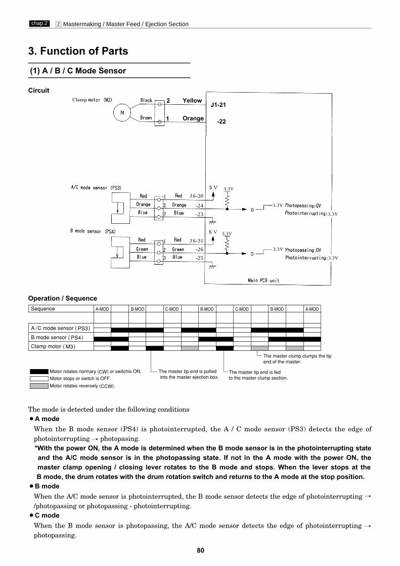
80
x Mastermaking / Master Feed / Ejection Sectionchap.2
The mode is detected under the following conditions2A mode
When the B mode sensor (PS4) is photointerrupted, the A / C mode sensor (PS3) detects the edge of photointerrupting f photopasing.*With the power ON, the A mode is determined when the B mode sensor is in the photointerrupting stateand the A/C mode sensor is in the photopassing state. If not in the A mode with the power ON, the master clamp opening / closing lever rotates to the B mode and stops. When the lever stops at the B mode, the drum rotates with the drum rotation switch and returns to the A mode at the stop position.
2B modeWhen the A/C mode sensor is photointerrupted, the B mode sensor detects the edge of photointerrupting //photopassing or photopassing - photointerrupting.
2C modeWhen the B mode sensor is photopassing, the A/C mode sensor detects the edge of photointerrupting fphotopassing.
(1) A / B / C Mode Sensor
Circuit
Operation / Sequence
3. Function of Parts
J1-21
-22
2
1
Yellow
Orange
J6-30
-24
-23
J6-31
-26
-25
3.3V
3.3V
3.3V
3.3V
3.3V
3.3V
Clamp

x Mastermaking / Master Feed / Ejection Sectionchap.2
81
4. Returning Operation Flowchart When the Power Is Cut Off AccidentallyThe machine returns to the initial state automatically when the power is turned off mistakenly during processing mastermaking, plate-detaching and master-attaching simultaneously or when the power returns afterit is interrupted.
Power ON
Detachment/attachment process
"---WAIT---" display
Attachment/detachmentoperation continues
"MASTER SET MISS"displayed?
Open the document receiving tray
Remove the mis-set master
Close the document receiving tray
Standby
OK monitor lights outInitial desplay
Is the state the sameas the previous state (before the power is turned OFF)?
Process other thandetachment/attachment
"---WAIT---" lights out
no
Power ON
yes

82
c Paper Feed Sectionchap.2
1. DescriptionFeeding of the paper is performed by the paper separator (employing the center separation method) and paperfeed roller (there is no corner finger). Elevation of the feed tray is powered by the elevator motor. Paper fed bythe paper separator and paper feed roller is fed further by the timing roller and guide roller to the pointwhere its leading edge is sandwiched between the drum and the press roller. Then the pression of the timingroller and guide roller is released (by moving the guide roller upward several mm), so that the paper is fedthrough at a speed equal to the circumferential speed of the drum and press roller. The press roller sensorsenses the paper feed condition; if a feed error occurs, the message “PAPER LEFT JAM” is displayed. Fordetails, see “1.Paper Jam Detection Timing” in chapter 2 (n Paper ejection section). \See page 107
cPaper Feed Section
Paper
Drum
23S0274
Paper separator
Paper feed roller
Elevator motor
Feed traySupplemental paper tray
Timing roller
Press roller
Guide roller
P roll sensor
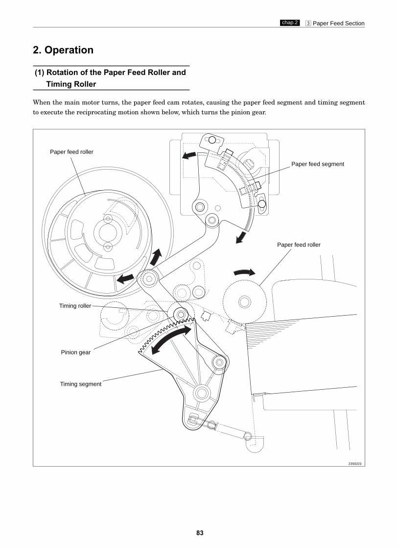
83
c Paper Feed Sectionchap.2
Paper feed roller
Timing roller
Paper feed segment
Timing segment
Pinion gear
Paper feed roller
When the main motor turns, the paper feed cam rotates, causing the paper feed segment and timing segmentto execute the reciprocating motion shown below, which turns the pinion gear.
2. Operation
(1) Rotation of the Paper Feed Roller andTiming Roller
23S0223
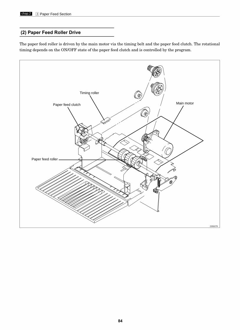
84
c Paper Feed Sectionchap.2
The paper feed roller is driven by the main motor via the timing belt and the paper feed clutch. The rotationaltiming depends on the ON/OFF state of the paper feed clutch and is controlled by the program.
(2) Paper Feed Roller Drive
Paper feed roller
Main motorPaper feed clutch
Timing roller
23S0279

85
c Paper Feed Sectionchap.2
Timing roller is actuated to rotate by the pinion gear and spring clutch. When the paper feed cam rotates, thereciprocating motion of the timing roller segment is transmitted to the pinion gear, and the spring clutchworks to rotate the Timing roller in the direction of conveyance.
(3) Driving of the Timing Roller
Timing roller
Paper feed cam
Spring clutch
Spring clutch
Pinion gear
Paper feed segment
23S0275

86
c Paper Feed Sectionchap.2
23S0286
23S0287
After the Press roller is pressed to the drum, the printing paper is gripped firmly with the drum and Pressroller, the Guide roller is released from the Timing roller. This is called "escaped". Escape timing is within aperiod when the printing paper is conveyed about 10 mm after it is gripped with the drum and Press roller.
(4) Escape the Guide Roller
¡When the timing is too late, the printing paper is gripped at two places too long. Thusmaster elongation and slippage occur.
¡On the contrary, when the timing is too early, the printing paper is not gripped at all, and itis not well settled. Thus creasing of paper and dispersion of the printing position occurs.
IMPORTANT :
Escape cam
Escape cam
Timing roller
Timing roller
Escape lever
Guide roller
Press roller
Guide roller
Drum
Paper
Drum
Press roller
about10mm
about10mm

87
c Paper Feed Sectionchap.2
The “paper feed length” is the length by which the paper feed roller feeds out the print paper. When the paperfeed roller feeds out the print paper, the guide roller is pressed against the timing roller and does not rotate;as a result, the paper arches up between the paper separator and the timing roller, since the distance betweenthese two items is only 80mm, while the length by which the paper is fed out from the paper feed roller is95mm. This arching has the effect of correcting any skewing of the paper (as the leading edge is held firmbetween the guide and timing rollers). It also has the effect of lessening the load on the timing roller when itfeeds the paper through, thus minimizing slippage.For feed amount, the leading edge of the paper is detected by the paper feed length sensor and paper feed iscontrolled by program( HELP mode H-66,67 ). HELP mode H-66,67 \ see p.284-285
¡If paper feed length is too large: the arching dimension will be too large, and if the paper isof a very stiff type, it will buckle up between the paper feed roller and the paper feed inlet(upper), causing a PAPER JAM error ("PAPER LEFT JAM").
¡If paper feed length is too small: the arching dimension will be too small, so that archingwill be unable to correct skewing of the paper, and skewing and wrinkling will be liable tooccur. Furthermore, the slippage that occurs when the timing roller feeds the paperthrough will be very large, resulting in printing position errors.
IMPORTANT :
(5) Paper Feed Length
Cam follower
Paper feed cam
Paper feed roller
Paper
Guide roller
Paper feed length sensor
Paper separator
Timing roller
23S0260

88
c Paper Feed Sectionchap.2
The printing position is adjusted by changing thetiming of the paper toward the drum with thePRINTING POSITION ADJUSTMENT , keyon the control panel.
Description
When the PRINTING POSITION ADJUSTMENT
, key on the control panel is pressed, the link
cam is driven by the motor. As the link cam moves,the cam follower position (bearing) from the paperfeed cam changes. Accordingly drive timing for thetiming roller can be changed.
2Press the key ;Cam follower moves in the direction of : e Drive timing of the timing roller becomes earlier.
Paper timing becomes earlier, and the picture image moves backward.2Press the key ;
Cam follower moves in the direction of : b Drive timing of the timing roller becomes later.Paper timing becomes later, and the picture image moves forward.
(1) Printing Position Adjusting Mechanism
¡Pressing makes cam follow-er move in the b direction
¡Pressing makes cam follow-er move in the e direction
Timing roller
Link cam
Printing position motor
Standard position sensor
Paper feed cam
Top and bottomlimit sensor
Cam follower
23S0258
3. Functions of partsPRINTING POSITION ADJUSTMENT key
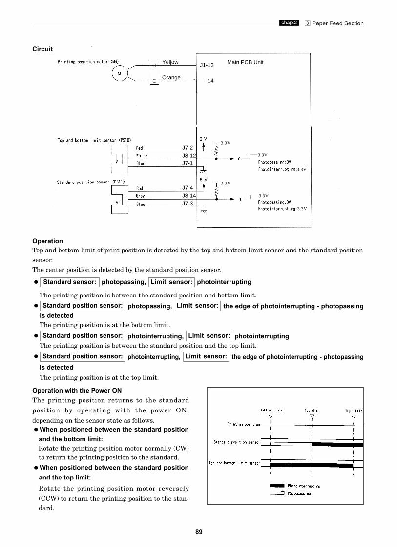
89
c Paper Feed Sectionchap.2
Circuit
OperationTop and bottom limit of print position is detected by the top and bottom limit sensor and the standard positionsensor.The center position is detected by the standard position sensor.
2 photopassing, photointerrupting
The printing position is between the standard position and bottom limit.
2 photopassing, the edge of photointerrupting - photopassingis detectedThe printing position is at the bottom limit.
2 photointerrupting, photointerruptingThe printing position is between the standard position and the top limit.
2 photointerrupting, the edge of photointerrupting - photopassingis detectedThe printing position is at the top limit.
Limit sensor:Standard position sensor:
Limit sensor:Standard position sensor:
Limit sensor:Standard position sensor:
Limit sensor:Standard sensor:
Operation with the Power ONThe printing position returns to the standard
position by operating with the power ON,
depending on the sensor state as follows.2When positioned between the standard position
and the bottom limit:Rotate the printing position motor normally (CW)to return the printing position to the standard.
2When positioned between the standard positionand the top limit:Rotate the printing position motor reversely(CCW) to return the printing position to the stan-dard.
J1-13
-14
Main PCB UnitYellow
Orange
J7-2J8-12J7-1
J7-4J8-14J7-3
3.3V
3.3V
3.3V
3.3V
3.3V
3.3V
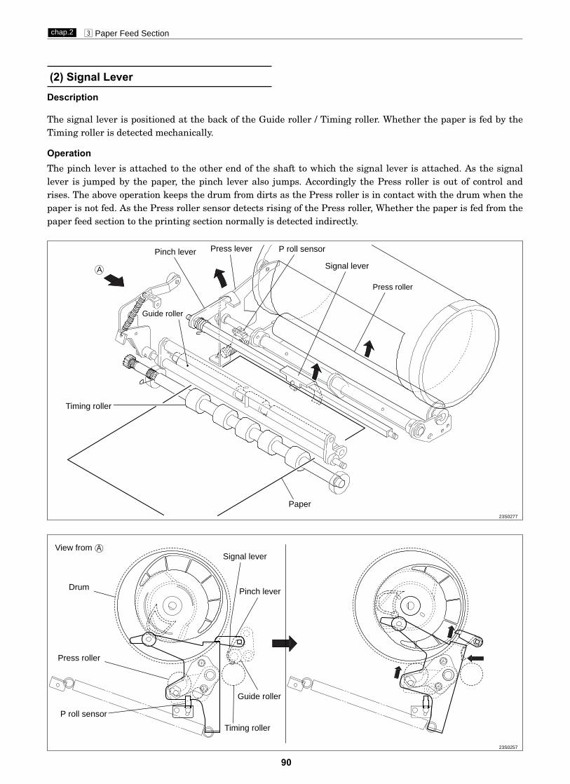
90
c Paper Feed Sectionchap.2
Description
Operation
View from
Pinch leverDrum
P roll sensor
Press roller
Timing roller
Guide roller
Signal lever
(2) Signal Lever
The signal lever is positioned at the back of the Guide roller / Timing roller. Whether the paper is fed by theTiming roller is detected mechanically.
The pinch lever is attached to the other end of the shaft to which the signal lever is attached. As the signallever is jumped by the paper, the pinch lever also jumps. Accordingly the Press roller is out of control andrises. The above operation keeps the drum from dirts as the Press roller is in contact with the drum when thepaper is not fed. As the Press roller sensor detects rising of the Press roller, Whether the paper is fed from thepaper feed section to the printing section normally is detected indirectly.
Paper
Signal lever
Press roller
P roll sensor
Timing roller
Guide roller
Press leverPinch lever
A
23S0277
23S0257

91
c Paper Feed Sectionchap.2
(3) Feed Tray (Elevator) Upper Limit Sensor
Description
Circuits
Operation
The feed tray (elevator) upper limit sensor senses decrease of the paper pile, and the upper limit position ofthe feed tray. It does so by detecting the up/down motion of the paper feed shaft.
Sensing of feed tray upper limit2When the feed tray rises, the paper in it presses the paper feed roller upward, making the paper feed shaft
lever (photointerrupter) rotate upwards about its fulcrum, until it no longer obstructs the sensor’s lightbeam. Restoration of the sensor’s light beam signals that the paper tray has reached the upper limit, andtriggers stopping of the feed tray’s rise.
Sensing of paper decrease2As printing progresses and the paper decreases, the paper feed roller gradually descends, until it obstructs
the sensor’s light beam. When this happens, the feed tray is raised until the light beam is restored.If the light beam is not restored within about 30 seconds of the sending of the RAISE FEED TRAYcommand, error E002 (elevator lock) is displayed.
23S0224
Paper feed roller
Paper tray upper limit sensor
PaperFulcrum
Paper feed shaft lever
Feed tray (elevator) upper limit sensor
Main PCB Unit
Red
Light blue
J8-20123 -24
Light green -13
3.3V5V
03.3V Photopass : 0V
Photointerrupting : 3.3V
23S0301

92
c Paper Feed Sectionchap.2
(4) Feed Tray (Elevator) Lower Limit Switch
Description
Circuits
Operation
This is a micro switch (SM6) that senses the lower limit position of the feed tray.
When the feed tray rises, the bracket disengages from the switch and the switch closes. When the feed traydescends to its lower limit position, the bracket engages the switch’s actuator, opening the switch.If the switch does not open within about 30 seconds of the sending of the LOWER FEED TRAY command, errorE002 (elevator lock) is displayed.
2Lower limit position
Feed tray (elevator) lower limit switchLower limit (PUSH) : OPEN
Main PCB Unit
Light blue
Light blue
J8-11
-23
3.3V
3.3V0
ScrewsElevator
lower limit switch
Connector

93
c Paper Feed Sectionchap.2
(5) Paper Sensor
Description
Circuits
Operation
Senses presence/absence of paper in the feed tray. When the paper in the tray runs out, the message "SETPRINT PAPER" is displayed and printing stops.
When there is no paper, the lever moves away and the sensor opens. When paper is placed inside, the leverpresses the actuator and the sensor closes. When an absence of paper is detected, the message "SET PRINTPAPER" is displayed on the operation panel.2When absence of paper is sensed, mastermaking, printing and test printing are not possible.2If the paper runs out during printing, "SET PRINT PAPER" is displayed on the operation panel, printing is
stopped, and the feed tray descends to its lower limit position.2If the paper runs out during platemaking, operation continues until the end of the mastermaking process,
then operation stops (without proceeding to the printing process), and the feed tray descends to its lowerlimit position.
¡When there is no paper :
23S0226
Photointerrupting
Photopassing
Actuator
Paper sensor
¡When there is paper placed :
Paper sensorClosed when paper presentOpen when paper absent
Main PCB Unit
Red
Blue
J6-32123 -15
Purple -16
3.3V
03.3V Photopass : 0V
5V
Photointerrupting : 3.3V
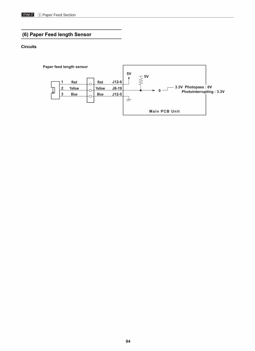
94
c Paper Feed Sectionchap.2
(6) Paper Feed length Sensor
Circuits
Paper feed length sensor
Main PCB Unit
Red
Blue
J12-6123 J12-5
YellowRed
BlueYellow J8-19
5V5V
03.3V Photopass : 0V
Photointerrupting : 3.3V
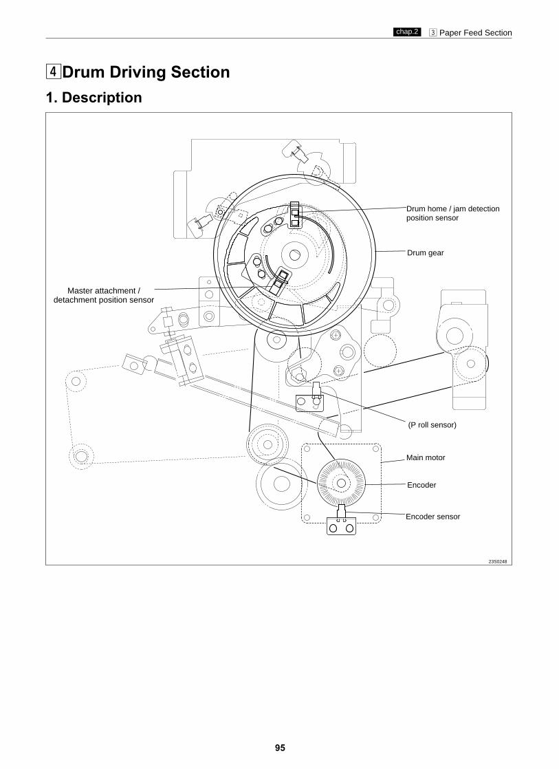
95
c Paper Feed Sectionchap.2
vDrum Driving Section1. Description
Encoder sensor
Encoder
Main motor
Drum gear
Drum home / jam detectionposition sensor
(P roll sensor)
23S0248
Master attachment /detachment position sensor

96
v Drum Driving Sectionchap.2
(1) Home Position / Jam DetectionPosition Sensor
2. Function of Parts
The home position / jam detection position sensor detects the drum home position and jam detection position.2The drum home position is the position where the drum stops at the same time when a beep sounds after
the jog switch (drum rotator switch) is kept pressing.2The jam detection position is the timing to check paper jamming in the paper ejection section.2Paper jamming in the paper ejection section is checked in the above timing with the jam sensor (photo-
receiving) and P roll sensor.
OperationThe home position / jam detection position sensor is positioned while the drum is rotating as follows:-2The home position is detected with the edge of photointerrupting / photopassing.2The jam detection position is detected with the edge of photopassing / photointerrupting.
Circuit
23S0249
Drum home/jam detectionposition sensor
Drum home/jam detectionposition edge
Jam detection position edge
Drum home position / jam detection position sensor (PS5)
Main PCB Unit
Red
Blue
J6-28123 -19
Yellow -20
3.3V5V
03.3V Photopass : 0V
Photointerrupting : 3.3V
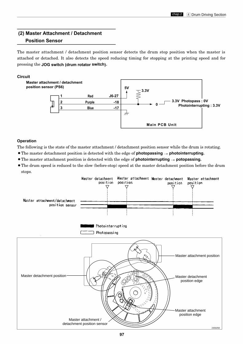
97
v Drum Driving Sectionchap.2
(2) Master Attachment / DetachmentPosition Sensor
The master attachment / detachment position sensor detects the drum stop position when the master isattached or detached. It also detects the speed reducing timing for stopping at the printing speed and forpressing the JOG switch (drum rotator switch).
OperationThe following is the state of the master attachment / detachment position sensor while the drum is rotating.2The master detachment position is detected with the edge of photopassing f photointerrupting.2The master attachment position is detected with the edge of photointerrupting f potopassing.2The drum speed is reduced to the slow (before-stop) speed at the master detachment position before the drum
stops.
Circuit
23S0250
Master detachment position
Master attachment position
Master detachmentposition edge
Master attachmentposition edge
Master attachment /detachment position sensor
Master attachment / detachmentposition sensor (PS6)
Main PCB Unit
Red
Blue
J6-27123 -17
Purple -18
3.3V5V
03.3V Photopass : 0V
Photointerrupting : 3.3V
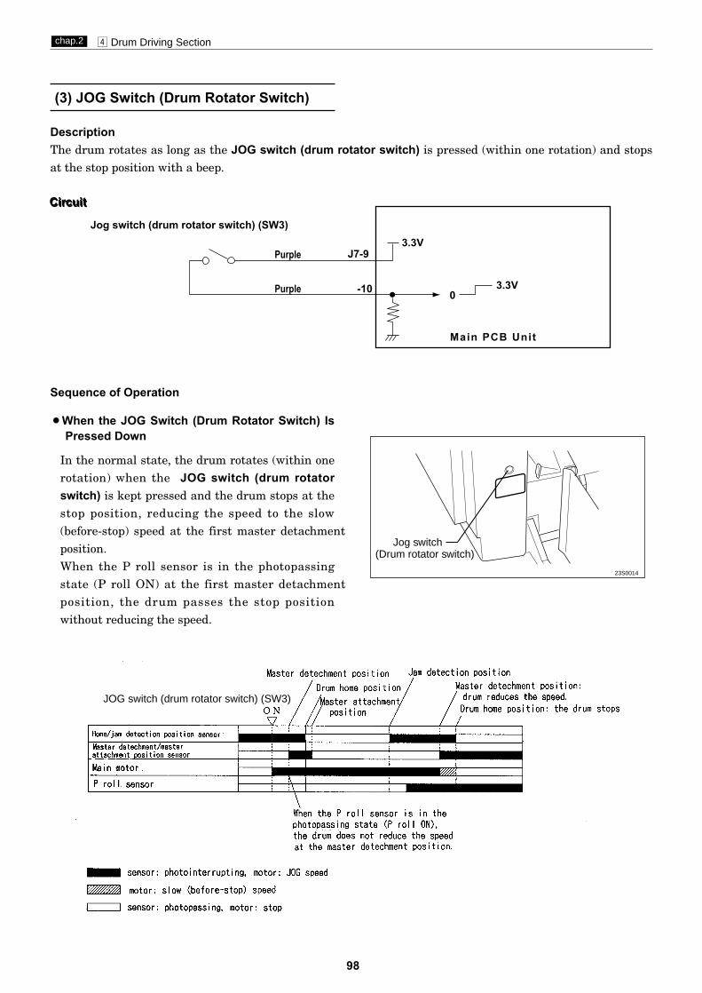
98
v Drum Driving Sectionchap.2
DescriptionThe drum rotates as long as the JOG switch (drum rotator switch) is pressed (within one rotation) and stopsat the stop position with a beep.
In the normal state, the drum rotates (within onerotation) when the JOG switch (drum rotatorswitch) is kept pressed and the drum stops at thestop position, reducing the speed to the slow(before-stop) speed at the first master detachmentposition.When the P roll sensor is in the photopassingstate (P roll ON) at the first master detachmentposition, the drum passes the stop positionwithout reducing the speed.
Circuit
(3) JOG Switch (Drum Rotator Switch)
JOG switch (drum rotator switch) (SW3)
2When the JOG Switch (Drum Rotator Switch) IsPressed Down
Sequence of Operation
Jog switch (drum rotator switch) (SW3)
Main PCB Unit
Purple
Purple
J7-9
-10
3.3V
3.3V0
Circuit
Jog switch(Drum rotator switch)
23S0014

99
v Drum Driving Sectionchap.2
(4) Control of the Main Motor
Circuit
Encoder sensor (PS7)
DC24V
Main motor (M1)
Main PCB Unit
Red
Red
Black
BrownBrownBlueBlue
Blue
J8-18
J9-3-4-1-2
J10-4
-3
123 -17
Gray -21
3.3V5V
03.3V Photopass : 0VPhotointerrupting : 3.3V

100
v Drum Driving Sectionchap.2
1. Rotation Speed Control by Encoder SensorThe encoder sensor detects the main motor rotation. The main PCB Unit controls the number of mainmotor rotations with the encoder sensor signal. The encoder sensor signal is transmitted to the main PCBUnit as encoder dividing signal . The number of main motor rotations is checked with the HELP05.
HELP mode H-05 \ see p.234
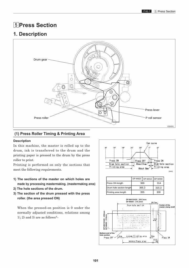
101
b Press Sectionchap.2
bPress Section1. Description
(1) Press Roller Timing & Printing Area
DescriptionIn this machine, the master is rolled up to thedrum, ink is transferred to the drum and theprinting paper is pressed to the drum by the pressroller to print.Printing is performed on only the sections thatmeet the following requirements.
1) The sections of the master on which holes aremade by processing mastermaking. (mastermaking area)
2) The hole sections of the drum.3) The section of the drum pressed with the press
roller. (the area pressed ON)
When the pressed-on position is 0 under thenormally adjusted conditions, relations among1), 2) and 3) are as follows*-
Drum gear
Press roller
Press lever
P roll sensor
DP-M410
369 314
315.3365.3
355 300
Press ON length
Drum hole section length
Printing area length
23S0251
DP-M410/420 : 365.3mmDP-M400 : 315.3mm
DP-
M41
0/42
0 : 2
50m
mD
P-M
400
: 210
mm
Center of the master clamp shaft
Bottom end of thehole section
DP-M420 DP-M400
9mm
(mm)
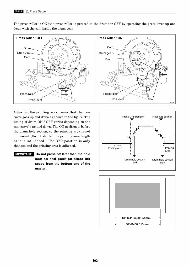
102
b Press Sectionchap.2
The press roller is ON (the press roller is pressed to the drum) or OFF by operating the press lever up anddown with the cam inside the drum gear.
Press roller : OFF Press roller : ON
Do not press off later than the holesection end position since inkseeps from the bottom end of themaster.
IMPORTANT :
DP-M410/420:355mm
DP-M400:315mm
Adjusting the printing area means that the camcurve goes up and down as shown in the figure. Thetiming of drum ON / OFF varies depending on thecam curve`s up and down. The ON position is beforethe drum hole section, so the printing area is notinfluenced. (Do not shorten the printing area lengthas it is influenced.) The OFF position is onlychanged and the printing area is adjusted.
Drum
Drum gear
Cam
Press roller
Press lever
Drum
Drum gear
Cam
Press roller
Press lever23S0252
Press OFF position Press ON position
Drum hole sectionend
Drum hole sectionstart
Printingarea
Printing area

103
b Press Sectionchap.2
(1) Press Roller (P Roll) Sensor
The P roll sensor detects up and down of the press roller.The press roller only ascends when the paper is fed from the paper feed section by the pinch lever. The P rollsensor also is used to know whether the paper is fed.
OperationThe P roll sensor position varies depending on the press roller position as follows:-• When the press roller is OFF (DOWN) : photointerrupting• When the press roller is ON (UP) : photopassing
Press roller : OFF Press roller : ON
Circuit
2. Function of Parts
Drum Drum
Press roller
Press lever
Press roller
Press lever
Pinch leverPinch lever
P roll sensor:photopassing
P roll sensor:photointerru
pting
23S0253
Press roll limit sensor(PS8)
Main PCB Unit
Red
Blue
J6-29123 -21
Light blue -22
3.3V5V
03.3V Photopassing : 0V
Photointerrupting : 3.3V
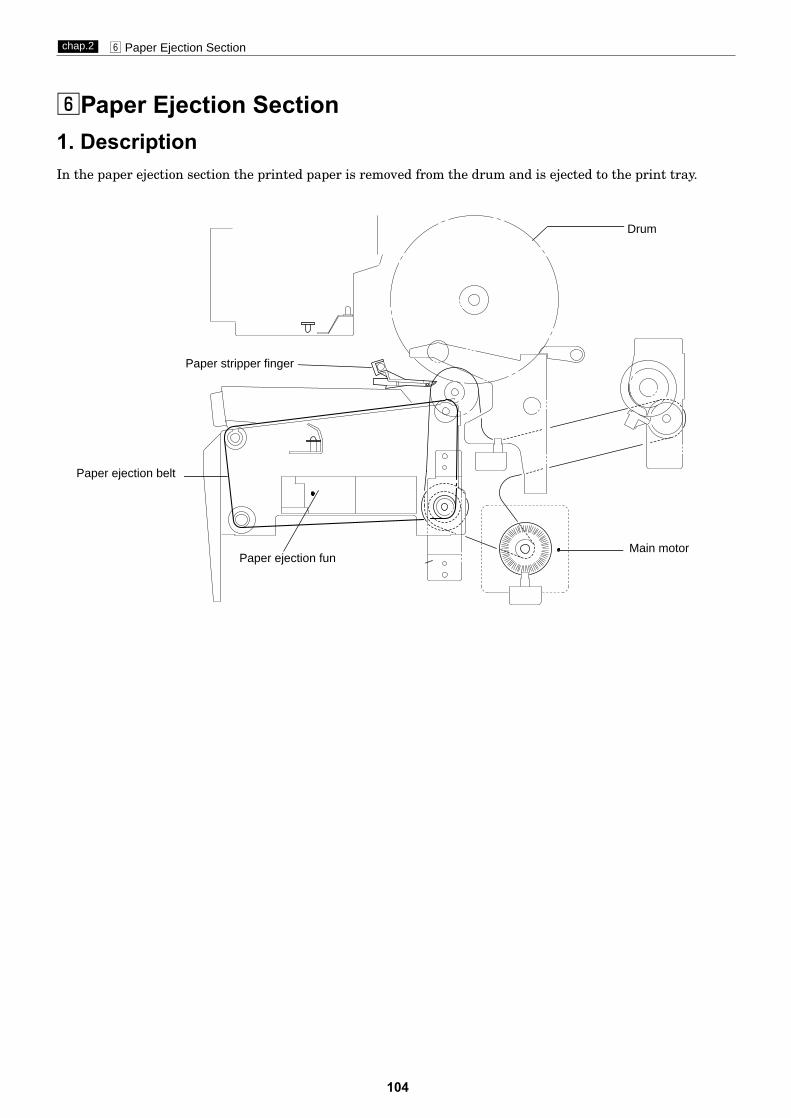
104
n Paper Ejection Sectionchap.2
nPaper Ejection Section1. DescriptionIn the paper ejection section the printed paper is removed from the drum and is ejected to the print tray.
Drum
Main motor
Paper stripper finger
Paper ejection belt
Paper ejection fun

105
n Paper Ejection Sectionchap.2
2. Functions of Parts
Mechanical Structure and OperationIn addition to the paper stripper finger installed in the center, there are two sub paper remover fingers onboth sides. There is an air diffuser on the tip of the finger. Compressed air transmitted from the air pump isblowed out of this hole to detach the tip end of the paper from the drum.
To remove the paper from the drum firmly, the gap between the tip of finger and the drum surface andbetween the tip of finger and the corner of the master clamp are adjusted as follows:-
Air pump
Sub paperstripper fingerPaper
stripper fingerSub paperstripper finger
Drumsurface
Approx0.5mm
Paper stripperfinger
(1) Paper Stripper Finger
23S0247
23S0278

106
n Paper Ejection Sectionchap.2
DescriptionThe jam sensor photo-receiving element is installed on the paper ejection fan unit and detects whether thepaper is ejected normally. When it is detected that the paper is not ejected normally, "PAPER RIGHT JAM"(ejection side) is displayed on the error display panel on the control panel.
OperationThe Jam photo-emitting PCB is installed in the master ejection box, and the photo-receiving PCB in the paperejection fan unit. HIGH with the optical path interrupted. LOW with the optical path passing.There are two cases of interruption; interrupted by the paper and the master ejection box is open.
Circuit
(2) Jam Sensor
23S0255
Paper ejection fun unit
Master ejection box
Jam sensor(Photo-emitting)
Jam sensor(Photo-receiving)
Master ejection sensor photo-emitting PCB
Jam sensorphoto-emitting PCB
Blue Blue
Pink
Jam sensorphoto-recieving PCB
-20
-19
-22
-21
-24
Main PCB Unit
Blue
Blue
Gray
Gray
PinkPink
Blue J7-233
6
1
2
1
2
3.3V
3.3V
3.3V
Gray4
5 Blue

107
n Paper Ejection Sectionchap.2
2Paper jamming on the ejection sideJAM1: The bottom end of the paper is not ejected.
When the jam sensor (light-emitting and light-receiving) is interrupted at the timing of jam detectionposition edge (photopassing \ photointerrupting) of the drum home / jam detection position sensorPS5.
JAM2: The tip end of the paper is not ejected.When the JAM sensor is not interrupted at all while the P roll sensor is in the state of photopassing(pressed ON).
JAM (stop): When the JAM sensor is interrupted as the master ejection box is open when the machine stops. The display is cleared when the sensor is in the state of photopassing.
2Paper jamming on the feeder sideJAM3: The paper does not pass the signal lever though the paper is fed. The P roll sensor is not in the state
of photopassing when the drum rotates twice after the paper feed solenoid is ordered ON.
1. Paper Jam Detection Timing
DescriptionPaper jamming is divided into two types: "PAPER RIGHT JAM" (ejection side) and "PAPER LEFT JAM"(feederside). Paper jamming is detected under the following conditions. When paper jamming is detected, "PAPERJAM" is displayed on the error display panel on the control panel, and the machine stops printing operation.The display is cleared by removing the cause of paper jam and pressing the STOP key or by restartingprinting.
Sequence of Operation
A4 LG B4 A4 LG B4 A4 LG B4
23S0256
Jam sensor(Photo-emitting)
Signal lever
P roll sensor
Master attachment/detachmentposition sensor
Jam sensor(Photo-receiving)
Drum home/jam detection position sensor

108
n Paper Ejection Sectionchap.2
(3) Paper aligning mechanism
DescriptionPaper can be aligned neatly by considering the ejection angle.Adjustments should be made in accordance with paper thickness.
For thinner paper: Set the lever in the upper position.For thicker paper: Set the lever in the lower position.
* Although the lever is usually set at the intermediate position for paper of normal thickness (65g/m2), thelever position should be adjusted depending on the condition of the paper.
Lever
Thinner paper
Ticker paper
23S0285
Normal(65g/ )

109
m Drum Sectionchap.2
mDrum Section
The ink control section is in the drum unit. The ink control section is supplied with ink in the ink packattached to the drum unit by the motor. The ink control section has an ink detection function, and is alwayssupplied with a fixed amount of ink. Printing darkness is adjusted by changing the gap between the squeegeeroller and the ink roller. Five color inks are available: black, red, blue, green and brown. Perform color printing to replace the drum unit for each color. (Press the drum rotation switch to the drum home position toreplace the drum unit.)In this machine, whether there is a drum or not is detected. If the drum is not attached properly, it is taken as"DRUM NOT SET", and "DRUM NOT SET" is displayed on the control panel.
Ink detection PCB unit
Ink motor
Ink pack
Squeegee roller
Ink roller
1. Description

110
m Drum Sectionchap.2
2. Circuit
24V
24V
Main PCB Unit
OrangePink
BlueBrownBlack
OrangePink
BlueBrownBlack
RedBlack
BlueBrownBlack
J2-10
-9
J6-9J2-1
J6-10
28
394
312
12
Ink detection PCB Unit
Ink motor (M7)
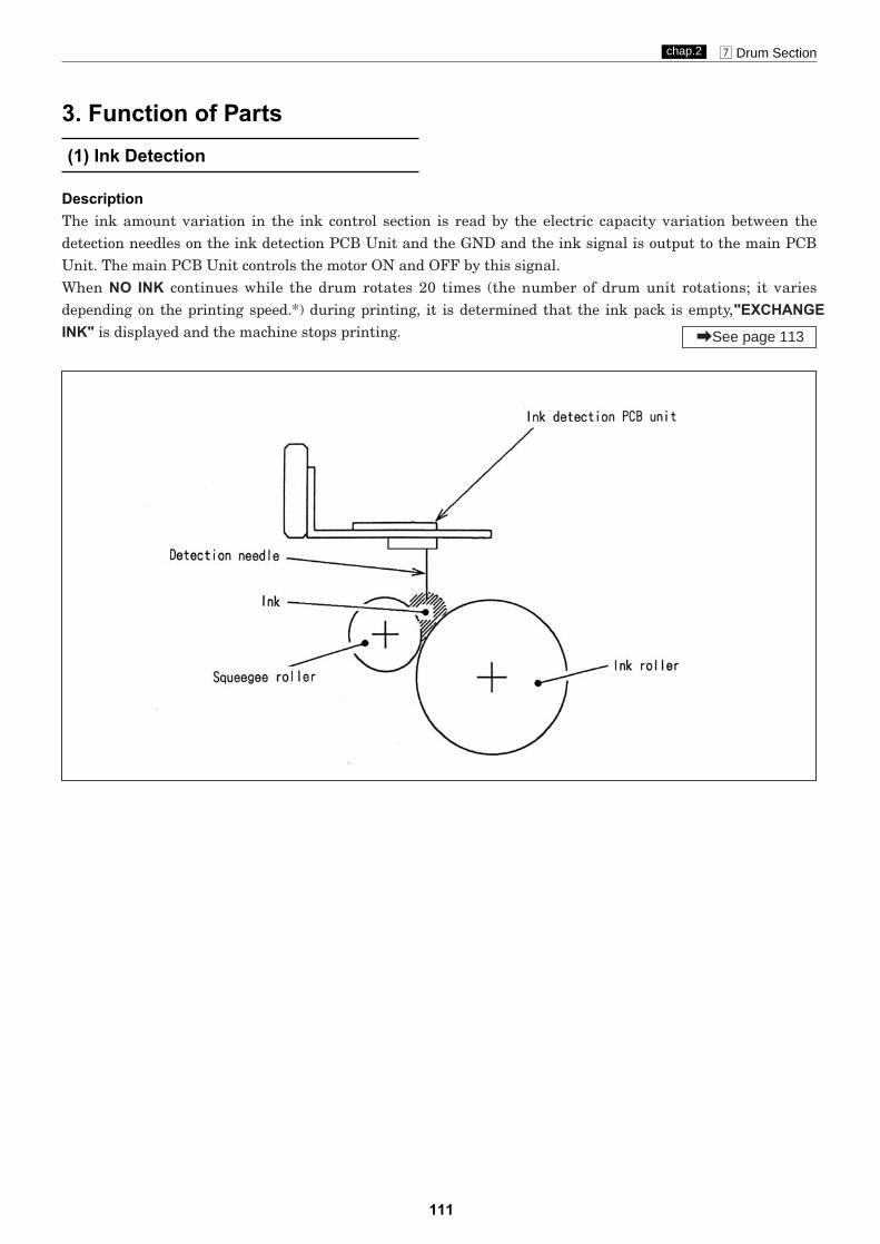
111
m Drum Sectionchap.2
DescriptionThe ink amount variation in the ink control section is read by the electric capacity variation between thedetection needles on the ink detection PCB Unit and the GND and the ink signal is output to the main PCBUnit. The main PCB Unit controls the motor ON and OFF by this signal.When NO INK continues while the drum rotates 20 times (the number of drum unit rotations; it variesdepending on the printing speed.*) during printing, it is determined that the ink pack is empty, "EXCHANGEINK" is displayed and the machine stops printing.
(1) Ink Detection
3. Function of Parts
\See page 113

112
m Drum Sectionchap.2
2Timing of the LED and the ink motor operation isas follows. The ink motor works during printing(driving output signal).
Ink detection PCB unit
LED CN1-2
No ink Light out +5V
Ink Light up 0V
1. LED Display and Output Signal on the InkDetection PCB Unit
2When the electric capacity variation between thedetection needles on the ink detection PCB Unitand GND is over the threshold value, the LED onthe ink detection PCB Unit lights up and the inksignal (0V) is output.
J2-9
Main PCB Unit
J6-10
J6-10
1
2
3
1 Cord 2 LED(red) 3 Detection needles
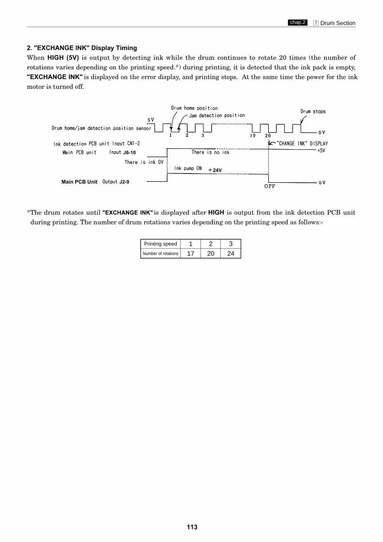
113
m Drum Sectionchap.2
2. "EXCHANGE INK" Display TimingWhen HIGH (5V) is output by detecting ink while the drum continues to rotate 20 times (the number ofrotations varies depending on the printing speed.*) during printing, it is detected that the ink pack is empty,"EXCHANGE INK" is displayed on the error display, and printing stops. At the same time the power for the inkmotor is turned off.
*The drum rotates until "EXCHANGE INK" is displayed after HIGH is output from the ink detection PCB unitduring printing. The number of drum rotations varies depending on the printing speed as follows:-
Printing speed
Number of rotations
1
17
2
20
3
24
J2-9Main PCB Unit
J6-10
24V

114
m Drum Sectionchap.2
DescriptionThe ink control section in the drum is supplied with ink in the ink pack by driving the ink motor.
OperationThe piston performs suction and release operation by moving up and down.
When the piston moves up, it draws ink from theink pack into the pump.
When the piston moves down, the pump releasesink.
Mechanical Structure
(2) Ink Pump

115
m Drum Sectionchap.2
DescriptionThe drum switch detects whether the drum is installed to the machine.When it is detected that there is no drum installed, "DRUM NOT SET" is displayed on the error display panelon the control panel the machine stops operation. When no drum is detected during operation, all theoperations stops emergently.
OperationWhen the drum is attached to the main body, the cam unit covers the pin and is locked firmly. The differenceof the cam unit prevents the cam unit from being loosened due to the machine vibration.When the pin is at the bottom of the cam unit difference, the drum SW is open as shown in the figure. Whenthe pin is over the cam unit difference, the drum SW is closed.
Circuit
(3)Drum Switch
LeverLever
Switch
Pin
Cam unit
23S0280
2No drum2Drum installed
J6-11
-12
3.3V
3.3V
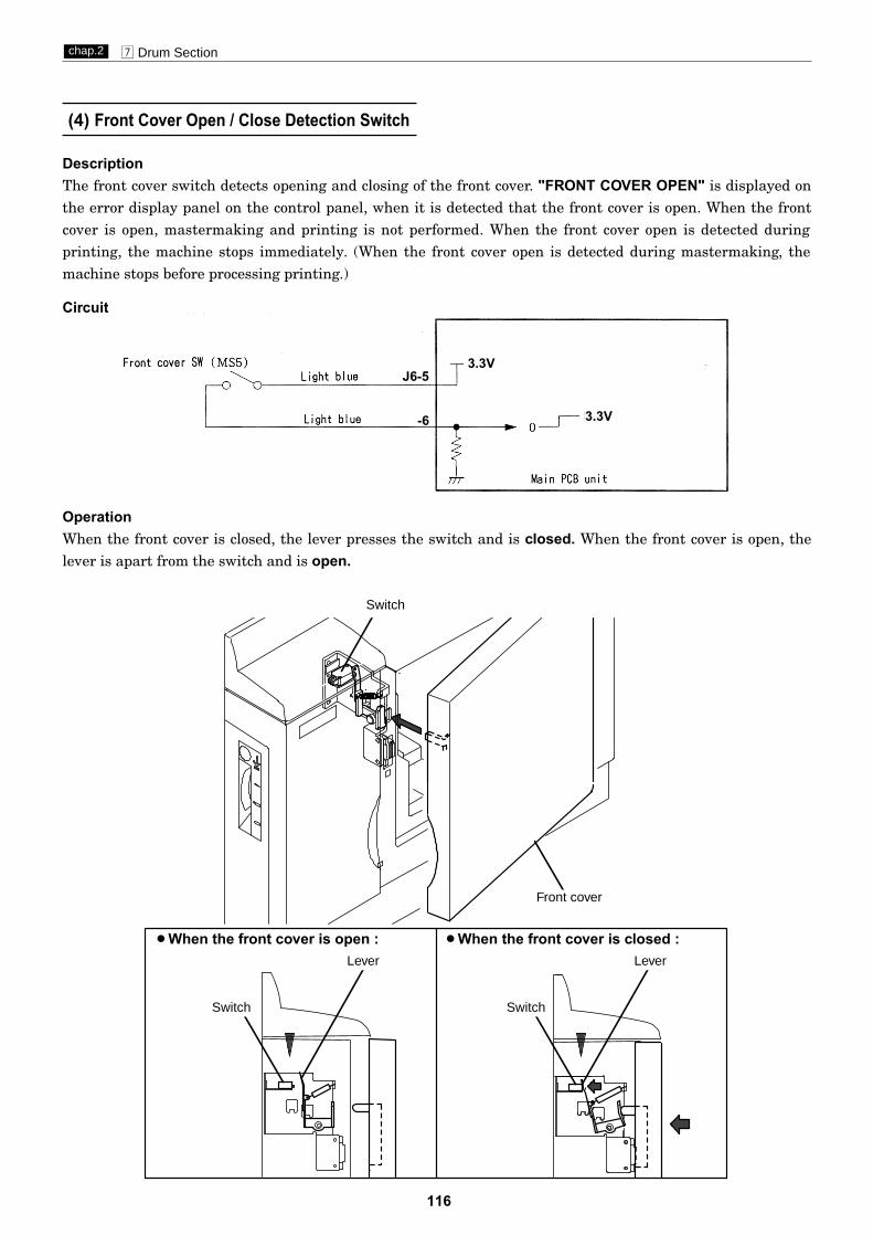
116
m Drum Sectionchap.2
DescriptionThe front cover switch detects opening and closing of the front cover. "FRONT COVER OPEN" is displayed onthe error display panel on the control panel, when it is detected that the front cover is open. When the frontcover is open, mastermaking and printing is not performed. When the front cover open is detected duringprinting, the machine stops immediately. (When the front cover open is detected during mastermaking, themachine stops before processing printing.)
OperationWhen the front cover is closed, the lever presses the switch and is closed. When the front cover is open, thelever is apart from the switch and is open.
Circuit
(4) Front Cover Open / Close Detection Switch
J6-5
-6
3.3V
3.3V
Switch Switch
Lever Lever
Front cover
2When the front cover is open : 2When the front cover is closed :
Switch

117
Chapter 3 Mechanism
z Exterior.......................................................................119(1) Removal of Document Cover................................119(2) Removal of Front Cover.......................................119(3) Removal of Scanner Outer Cover.......................120(4) Removal of Rear Cover........................................121(5) Removal of Main PCB Unit.................................121(6) Removal of Control Panel....................................123(7)Removal of Control Panel PCB ............................123(8) Removal of DC Regulated Power Supply............124
x Scanner Section........................................................125(1) Removal of Glass unit.........................................125(2) Removal of Reading Cover..................................126(3) Removal of Inverter PCB Unit............................126(4) Removal of Lamp Unit.........................................127(5) Removal of Lamp Cord........................................128(6) Removal of Slider A.............................................129(7) Removal of Slider B.............................................130
c Mastermaking / Master Feed and Ejection Section...131
Master Feed Section ...........................................131(1) Removal of Cutter Unit .......................................131(2) Removal of End Mark Sensor PCB Unit ............132(3) Removal of Thermal Head...................................133(4) Removal of Master Feed Unit .............................134
Master Ejection Section ......................................136(1) Removal of Master Ejection Box .........................136(2) Removal of Jam / Master Ejection Sensor
(Photo-emitting PCB Unit)..................................137(3) Removal of Rollup Motor .....................................137
Master Clamp opening/Closing Section...........138(1) Removal of Master Clamp Opening /
Closing Unit .........................................................138(2) Removal of Clamp Motor.....................................138(3) Removal of Timing Belt .......................................139
118
3
v Paper Feed Section....................................................140(1) Removal of Paper Sensor......................................140(2) Removal of Elevator Lower Limit Switch ...........140(3) Removal of Paper Feed Roller ..............................141(4) Removal of Paper Separator Unit........................141(5) Removal of Paper Feed Clutch Unit ....................142(6) Removal of Paper Feed Sensor.............................143(7) Removal of Timing Roller.....................................144
b Drum Driving Section................................................145(1) Removal of Sub-Frame.........................................145(2) Removal of Drum Gear.........................................146
n Paper Ejection Section..............................................147(1) Removal of Paper Stripper Finger /
Sub Paper Stripper Finger...................................147(2) Removal of Paper Ejection Fan Unit...................148(3) Removal of Paper Ejection Belt...........................149(4) Removal of Jam Sensor
(Photo-receiving PCB Unit)..................................149
m Drum Section.............................................................150(1) Removal of Screen ...............................................150(2) Removal of Master Clamp....................................151(3) Removal of Base Unit...........................................151(4) Removal of Outer Frame (Right) Unit.................152(5) Removal of Outer Frame (Left) Assy...................153(6) Removal of Inner Frame......................................154(7) Removal of Ink Pump...........................................155(8) Removal of Ink Motor...........................................155(9) Removal of Ink Detection PCB Unit....................156
•Always remove the power cord plug from the outlet beforestarting work.
•In principle, do not operate this machine with parts removed.
•When assembling:•Unless specified otherwise, perform the disassembly procedure in
reverse.•Make sure that screw types (radius, length) and locations are correct.•Be sure to use rosette washers when they are specified.
(Rosette washers are used with installation screws to prevent staticelectricity.)
•To ensure electrical current, a rosette washer is used with the installation screw on the ground wire. Be sure to use the rosettewasher during assembly.
•Cautions Regarding Disassembly and Assembly
CAUTION

(1) Removal of Document Cover
119
z Exteriorchap.3
z Exterior
1) Open the document cover.
S2002
S2004
Document cover
Screws
2) Remove the 2 screws shown. Slide the documentcover back 1cm, and then pull it up to remove it.
1) Open the front cover, and take out the drum unit.2) Open the master ejection box.
3) Remove the 6 screws indicated, then remove thefront cover.
(2) Removal of Front Cover
Screws
Screws
Screws
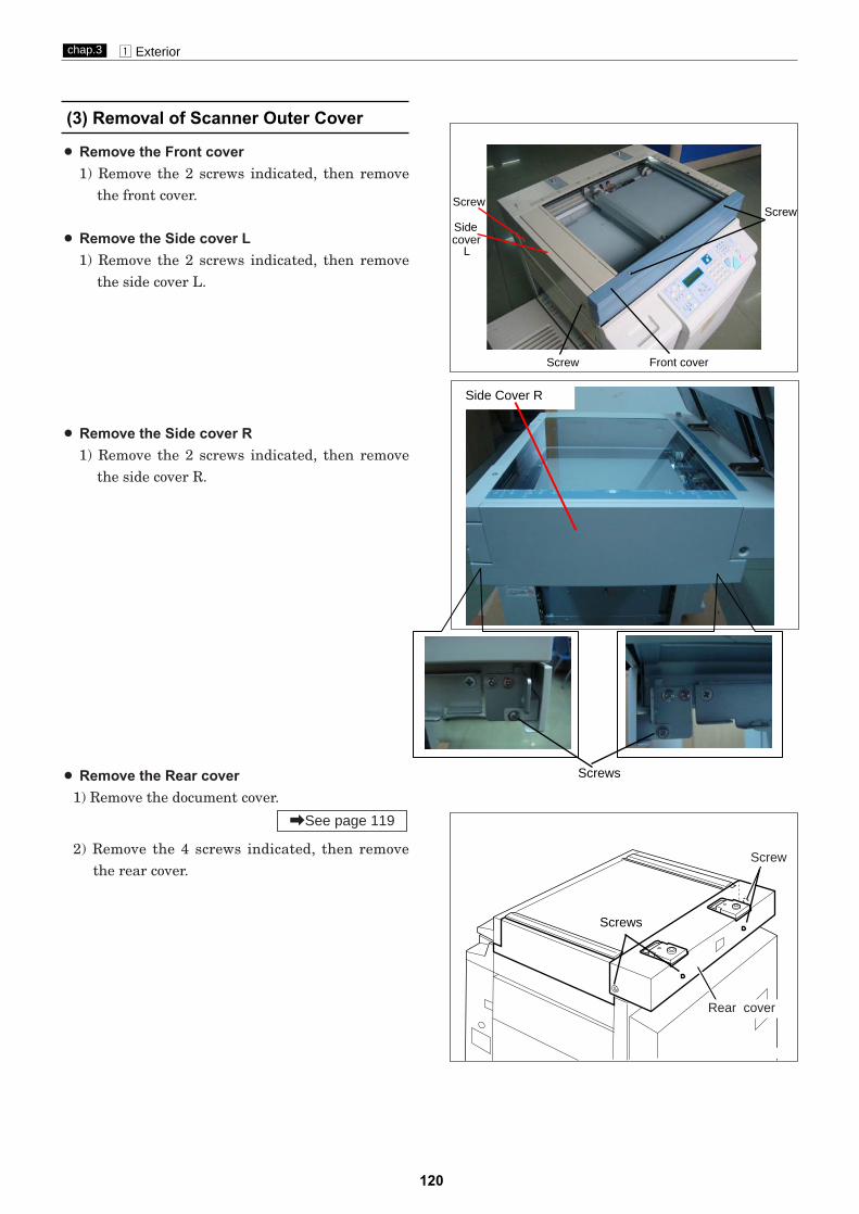
120
z Exteriorchap.3
(3) Removal of Scanner Outer Cover
Screws
¡ Remove the Front cover1) Remove the 2 screws indicated, then remove
the front cover.
¡ Remove the Side cover L1) Remove the 2 screws indicated, then remove
the side cover L.
¡ Remove the Side cover R1) Remove the 2 screws indicated, then remove
the side cover R.
¡ Remove the Rear cover1) Remove the document cover.
2) Remove the 4 screws indicated, then remove the rear cover.
\See page 119
Rear cover
Screw
ScrewScrew
Sidecover
L
Screw Front cover
Screws
Side Cover R

121
z Exteriorchap.3
(4) Removal of Rear Cover
1) Remove the 4 screws indicated, then remove therear cover.
24S005
Screws
Rear cover
Screws
(5) Removal of Main PCB Unit
1) Remove the scanner cover(L,R).
2) Press the Scanner switch to slide the scanner toits far position.
\See page 120
WARNING¡Always remove the power cord plug from
the outlet before replacing a PCB Unit.
Scanner switch
Screw ScrewConnector cover A
3) Loosen the 2 screws shown.4) Slide connector bracket A down.

122
z Exteriorchap.3
24S009
5) Remove the 4 screws indicated, then remove thebracket(F,R).
Screws
Screws
Bracket (F)
7) Press and hold the Scanner switch while slidingthe scanner all the way in the paper feed direction.
Bracket (R)
1) Remove the 2 screws.
2) Slide the PCB cover and remove it.
8) Remove the PCB cover.
Screw
PCBcover
6) Remove the screw indicated, then remove the PIN UNIT. Screw
PIN UNIT
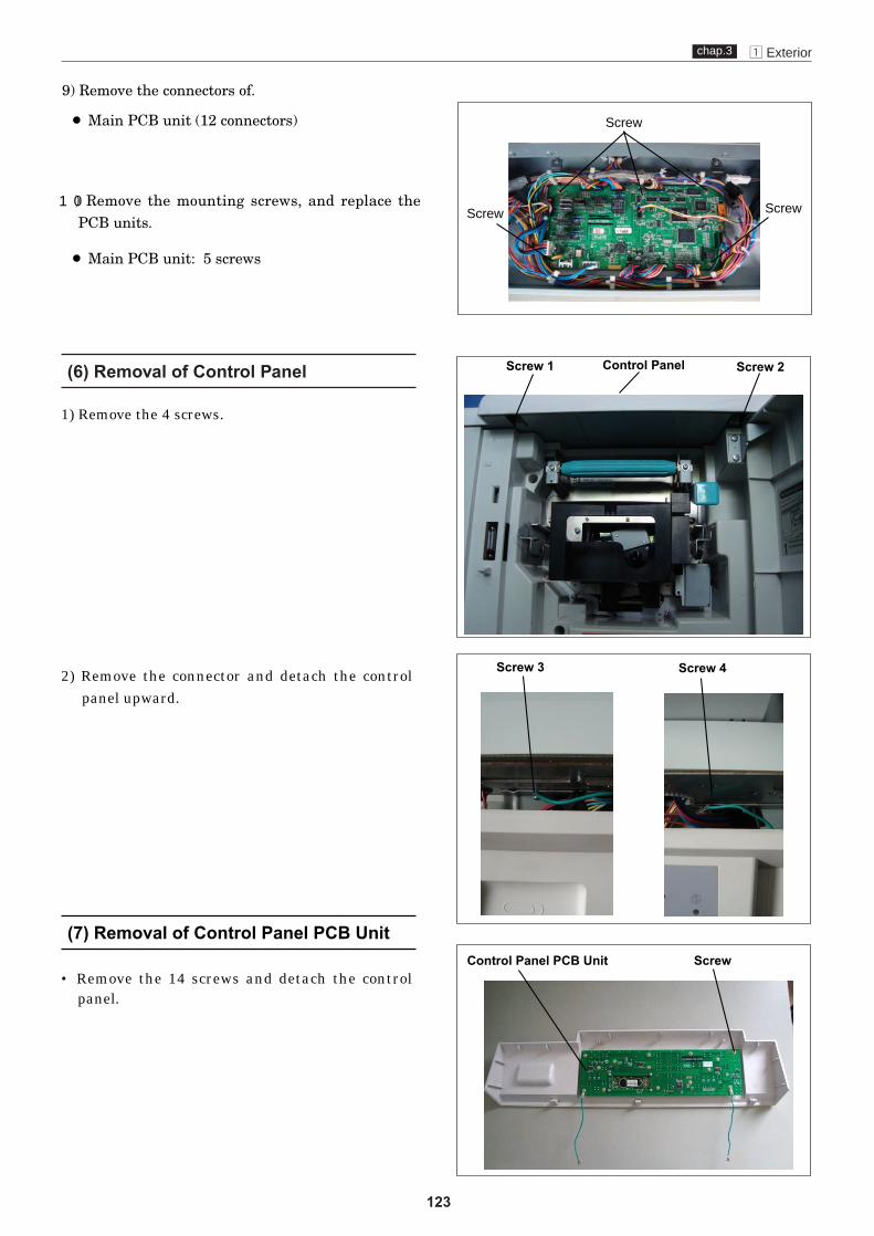
123
z Exteriorchap.3
(6) Removal of Control Panel
(7) Removal of Control Panel PCB Unit
1) Remove the 4 screws.
2) Remove the connector and detach the controlpanel upward.
• Remove the 14 screws and detach the controlpanel.
Control PanelScrew 1 Screw 2
Screw 3 Screw 4
Control Panel PCB Unit Screw
9) Remove the connectors of.
¡ Main PCB unit (12 connectors)
) Remove the mounting screws, and replace thePCB units.
¡ Main PCB unit: 5 screws
Screw Screw10
Screw
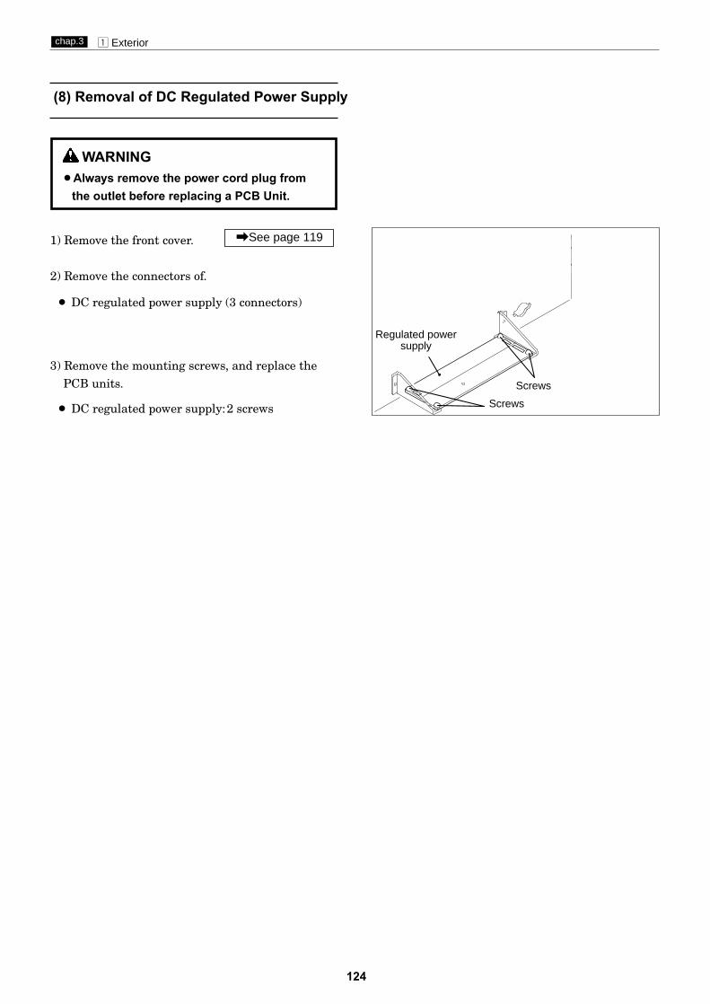
124
z Exteriorchap.3
1) Remove the front cover.
2) Remove the connectors of.
¡ DC regulated power supply (3 connectors)
3) Remove the mounting screws, and replace thePCB units.
¡ DC regulated power supply:2 screws
\See page 119
(8) Removal of DC Regulated Power Supply
Screws
Screws
WARNING¡Always remove the power cord plug from
the outlet before replacing a PCB Unit.
Regulated powersupply

125
x Scanner Sectionchap.3
(1) Removal of Glass unit
x Scanner Section
Do not dirt the shaiding plate.Clean it if it is dirty.
IMPORTANT :
3) Remove the 2 screws indicated, then
1) Remove the document cover.
2) Remove the Side Cover R.
\See page 119
\See page 120
pull out and remove the Glass unit
Screws
1
2
at the direction as right carefully.
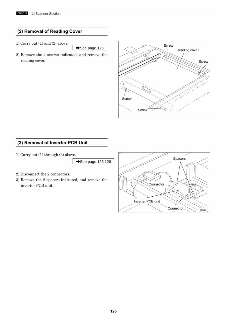
24S019
126
x Scanner Sectionchap.3
(2) Removal of Reading Cover
(3) Removal of Inverter PCB Unit
1) Carry out (1) through (3) above.
2) Disconnect the 2 connectors.3) Remove the 2 spacers indicated, and remove the
inverter PCB unit.
\See page 125,126
Reading cover
Screw
24S020
Inverter PCB unit
1) Carry out (1) and (2) above.
2) Remove the 4 screws indicated, and remove thereading cover.
\See page 125
Screw
Screw
Screw
Connector
Connector
Spacers

127
x Scanner Sectionchap.3
(4) Removal of Lamp Unit
24S021
Scanner R bracket
24S022
5) Turn the timing pulley, and move Slider A to theposition shown in the diagram.
Screw
Timing pulley
24S023
24S024
Lamp unit
Notch
1) Carry out (1) through (3) above.
2) Remove the scanner cover(L,R). 3) Remove the 7 spacers indicated, and remove the
scanner F bracket.4) Remove the 8 spacers indicated, and remove the
scanner R bracket.
\See page 120
\See page 125,126
Do not move Slider A by hand.IMPORTANT :
6) Remove the 3 screws indicated, and remove thelamp unit.
The lamp is fragile; handle it with care.IMPORTANT :
Reinstallation
¡ Insert the slotted parts of the lamp unit intothe grooves on the brackets.
¡ When attaching the scanner's front and rearbrackets:1. Align the notches on the left and right sides.2. When attaching the scanner's rear bracket,
be careful to not pinch the wiring.
Screw
Screw
ScrewsScrews
Screw
Screw
Screws
Screws
Screws
Scanner F bracket
Screw
Lamp unit
Bracket groove
Bracket groove
Notch
Notch
Notch
Slider A

128
x Scanner Sectionchap.3
24S025
(5) Removal of Lamp Cord
4) Remove the 4 screws indicated, and remove thelamp cord.
Connector
Screws
24S026
Lamp cord
1) Carry out (5) 1 through 4 above.
2) Remove the cord clamp.3) Disconnect the inverter PCB unit CN2 connector.
\See page 127 Cord clamp Inverter PCB unit
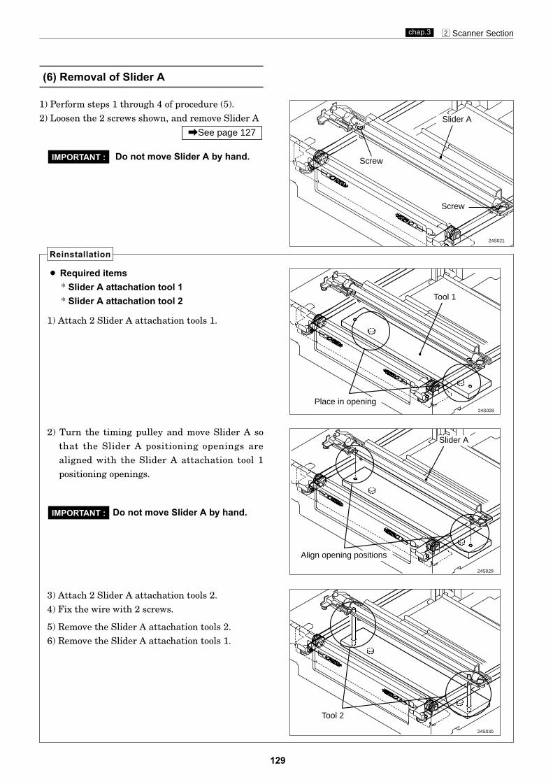
129
x Scanner Sectionchap.3
(6) Removal of Slider A
24S021
24S028
24S029
Place in opening
Slider A
1) Perform steps 1 through 4 of procedure (5).2) Loosen the 2 screws shown, and remove Slider A
\See page 127
Reinstallation
¡ Required items* Slider A attachation tool 1* Slider A attachation tool 2
Screw
Screw
Slider A
24S030
Tool 2
Tool 1
Align opening positions
Do not move Slider A by hand.IMPORTANT :
2) Turn the timing pulley and move Slider A sothat the Slider A positioning openings arealigned with the Slider A attachation tool 1positioning openings.
1) Attach 2 Slider A attachation tools 1.
3) Attach 2 Slider A attachation tools 2.4) Fix the wire with 2 screws.
5) Remove the Slider A attachation tools 2.6) Remove the Slider A attachation tools 1.
Do not move Slider A by hand.IMPORTANT :

130
x Scanner Sectionchap.3
(7) Removal of Slider B
24S031
24S032
24S033
¡ Required items* Wire fixing tools
1) Perform steps 1 through 3 of procedure (5).2) To prevent loosening of the wire, attach 2 wire
fixing tools, one before and one after the wire pulley.
Do not remove the wire fixing toolsbefore Slider B is attached.
IMPORTANT :
Reinstallation
Fix the wire with the tool
24S034
2) Place the wire on the pulley, both before andafter. \See page 159
Place in opening
Slider B
¡ Required items* Slider B attachation tool 1* Slider B attachation tool 2
Tool 2
Tool 1
Align opening positions
3) Move Slider B so that the Slider B positioningopenings are aligned with the Slider B attachation tool 1 positioning openings.
1) Attach 2 Slider B attachation tools 1.
4) Attach 2 Slider B attachation tools 2.
5) Place the spring on the hook(wire).
6) Remove the Wire fixing tools.
7) Remove the Slider B attachation tools 2.8) Remove the Slider B attachation tools 1.
Attach thespring
Fix the wire with the tool
3) Remove the wire from the spring, in 2 locationsbefore and after the spring.
4) Remove Slider B.
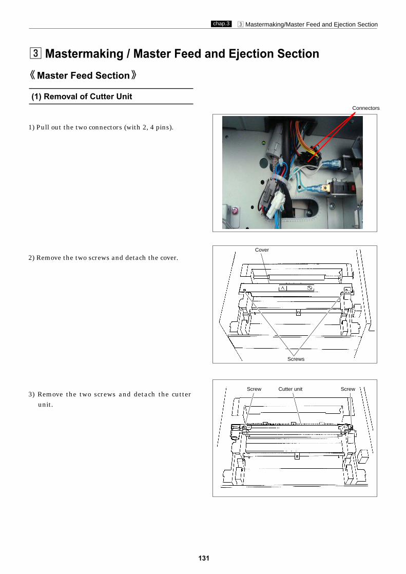
131
c Mastermaking/Master Feed and Ejection Sectionchap.3
c Mastermaking / Master Feed and Ejection Section
(1) Removal of Cutter Unit
Master Feed Section
Cover
Screws
Screw ScrewCutter unit
1) Pull out the two connectors (with 2, 4 pins).
2) Remove the two screws and detach the cover.
3) Remove the two screws and detach the cutterunit.
Connectors

132
c Mastermaking/Master Feed and Ejection Sectionchap.3
(2) Removal of End Mark Sensor PCB Unit.
ScrewsEnd-mark sensor 2
Screw Sensor cover
Connector
4) Adjust the end-mark sensor 2. Go to HELP-13 and set the document mode'Photo'. Rotate the sponge roller to adjust the sensor (10 or less in white section, 40 or more in black section) with VR.
1) Remove the screw and detach the sensor cover.
2) Pull out the connector (end-mark sensor 2).
3) Remove the two screws and detach the end-marksensor 2.

133
c Mastermaking/Master Feed and Ejection Sectionchap.3
(3) Removal of Thermal HeadGuide plate
Screws
Connectors
Bracket
Screw
Collar
1) Remove the two screws and detach the guideplate.
2) Pull out the two connectors.
3) Remove both screw and collar.
4) Remove the bracket from the bottom.
5) Remove the two screws with the collars to detachthe thermal head.
Do not touch the heat emissionparts of the thermal head.
IMPORTANT:
• The thermal head is sensitive to static electricity, sobefore touching it, be sure to touch ground to get ridof your body static. The head is also liable to corrode. To avoid corrosion,keep the head free of moisture and salinity, and donot touch its heat emission parts. Touching theseparts could scratch them.
Thermal head
Do not touch the heat emission parts
Screw
Collar

c Mastermaking/Master Feed and Ejection Sectionchap.3
134
(4) Removal of Master Feed Unit
2) Cut the two banding bands.
3) Pull out the two thermal head connectors.
4) Remove the two cord bands and pull out the fourconnectors.
1) Remove the two screws and detach the guideplate.
Guide plate
Screws
Thermal head connectors
Banding band
Connectors
Cord bands

135
c Mastermaking/Master Feed and Ejection Sectionchap.3
Screws Master feeding unit ScrewScrew
Screw Switch bracket
5) Remove the screw and take out the switch withthe switch bracket (with bundled wire connect-ed).
6) Remove the four screws and detach the masterfeeding unit.
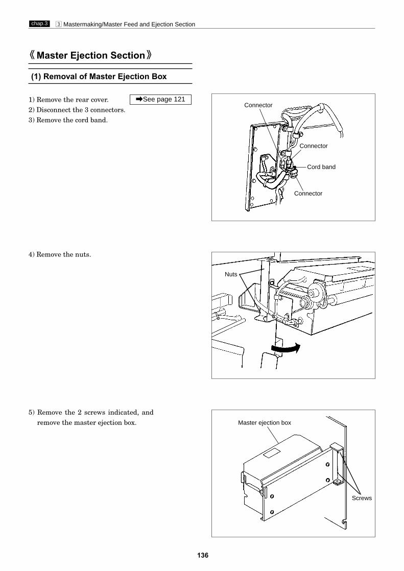
136
c Mastermaking/Master Feed and Ejection Sectionchap.3
1) Remove the rear cover. 2) Disconnect the 3 connectors.3) Remove the cord band.
\See page 121
4) Remove the nuts.
5) Remove the 2 screws indicated, and remove the master ejection box.
(1) Removal of Master Ejection Box
Master Ejection Section
Master ejection box
Screws
Nuts
Connector
Connector
Connector
Cord band

137
c Mastermaking/Master Feed and Ejection Sectionchap.3
(2) Removal of Jam / Master EjectionSensor (Photo-emitting PCB Unit)
1 ) Remove the master ejection box.
2) Remove the respective photo-emitting PCB unitsby removing the 2 screws.
1) Remove the master ejection box.
2) Remove the 1 screw indicated, and remove thecover.
3) Remove the timing belt from the pulley at thepart shown by the arrow.
4) Remove the 3 motor mounting screws indicated,and remove the roll - up motor.
Do not forget to adjust the tensionafter the motor is attached.
\See page 163
IMPORTANT :
(3) Removal of Roll - up Motor
Reinstallation
Jam sensorphoto-emitting
PCB unit
Screw
Cover
Screws Motor
Timing belt
Pulley
Master ejectionsensor photo-emitting PCB
unit
Screw
\See page 136
\See page 136
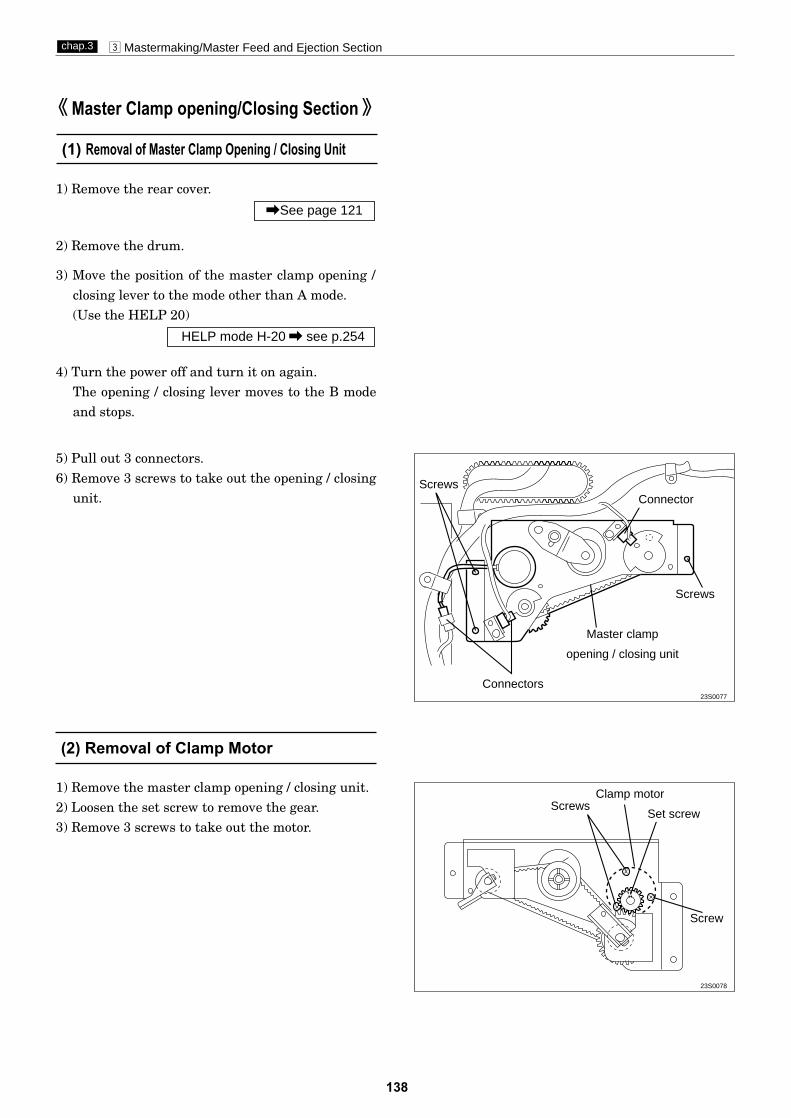
23S0078
138
c Mastermaking/Master Feed and Ejection Sectionchap.3
(1) Removal of Master Clamp Opening / Closing Unit
1) Remove the rear cover.
2) Remove the drum.
3) Move the position of the master clamp opening /closing lever to the mode other than A mode.(Use the HELP 20)
4) Turn the power off and turn it on again.The opening / closing lever moves to the B modeand stops.
HELP mode H-20 \ see p.254
\See page 121
5) Pull out 3 connectors.6) Remove 3 screws to take out the opening / closing
unit.
1) Remove the master clamp opening / closing unit.2) Loosen the set screw to remove the gear.3) Remove 3 screws to take out the motor.
Set screwScrews
Screw
(2) Removal of Clamp Motor
Master Clamp opening/Closing Section
23S0077
Screws
Connectors
Connector
Screws
Master clamp
opening / closing unit
Clamp motor

23S0080
23S0079
139
c Mastermaking/Master Feed and Ejection Sectionchap.3
1) Remove the master clamp opening / closing unit.
2) Loosen 2 screws to loosen the tension as shownin the figure.
\See page 138
3) Remove the screw to remove the angle.4) Remove the timing belt.
• Adjust tension by adjusting the master feed mas-ter clamp opening/closing lever and master ejec-tion master clamp opening/closing lever. Then fitthe timing belt on.
Adjust the A, B and C modes afterthe master clamp opening / closingunit is attached to the printer mainbody.
IMPORTANT :
Main frame R
Master ejection masterclamp opening/closing leverPosition hole
Position hole
Master feed master clampopening/closing lever
Master clampopening/closing unit
Tension Screws
Screw
Timing belt
Screw
(3) Removal of Timing Belt
\See page 164
Reinstallation
23S0082
\See page 165

1) Remove the front cover.
2) Remove the 2 screws indicated, then remove thebracket.
3) Disconnect the connector, and remove the eleva-tor lower limit switch.
\See page 119
140
v Paper Feed Sectionchap.3
(2) Removal of Elevator Lower Limit Switch
After reinstalling the elevator lowerlimit switch, carry out adjustmentof its clearance.
\For adjustment method see page 171
IMPORTANT :
Reinstallation
Feed tray
(1) Removal of Paper Sensor
1) Access HELP mode H-02, and use it to raise theelevator to its uppermost position.
HELP mode H-02 \ see p.236
2) Disconnect the connector, and remove the papersensor.
v Paper Feed Section
23S0083
23S0084
Paper sensor
Connector
ScrewsElevator
lower limit switch
Connector
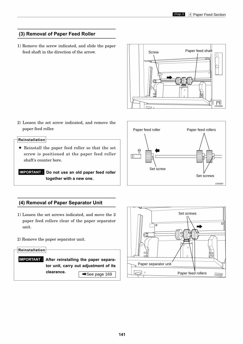
23S0088
23S0087
23S0086
141
v Paper Feed Sectionchap.3
(3) Removal of Paper Feed Roller
1) Remove the screw indicated, and slide the paperfeed shaft in the direction of the arrow.
(4) Removal of Paper Separator Unit
1) Loosen the set screws indicated, and move the 2paper feed rollers clear of the paper separatorunit.
2) Remove the paper separator unit.
2) Loosen the set screw indicated, and remove thepaper feed roller.
¡ Reinstall the paper feed roller so that the setscrew is positioned at the paper feed rollershaft's counter bore.
Do not use an old paper feed rollertogether with a new one.
IMPORTANT :
Reinstallation
After reinstalling the paper separa-tor unit, carry out adjustment of itsclearance.
IMPORTANT :
Reinstallation
Screw Paper feed shaft
Paper feed roller Paper feed rollers
Paper feed rollers
Set screw
Set screws
Set screws
Paper separator unit
\See page 169
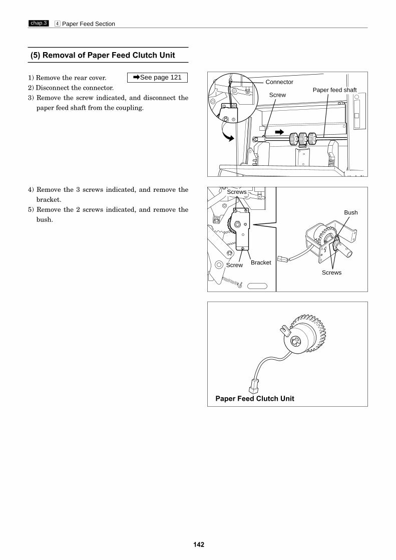
142
v Paper Feed Sectionchap.3
(5) Removal of Paper Feed Clutch Unit
1) Remove the rear cover. 2) Disconnect the connector.3) Remove the screw indicated, and disconnect the
paper feed shaft from the coupling.
\See page 121
4) Remove the 3 screws indicated, and remove thebracket.
5) Remove the 2 screws indicated, and remove thebush.
Screw
ConnectorPaper feed shaft
Bush
Screws
ScrewsScrew Bracket
Paper Feed Clutch Unit

23S0094
23S0093
143
v Paper Feed Sectionchap.3
(6) Removal of Paper Feed Sensor
1) Remove the paper feed shaft.
2) Remove the paper separator unit.
3) Remove the 4 screws indicated, and remove thebracket.
\See page 140
\See page 141 (3) Paper feed shaftBracket
Screws Screws
Paper feed sensorConnector
Screw
4) Disconnect the connector.5) Remove the screw indicated, and remove the
paper feed sensor.

144
v Paper Feed Sectionchap.3
24S037
24S038
24S035
24S036
(7) Removal of Timing Roller
1) Remove the front cover.
2) Remove the rear cover.
3) Remove the drum.4) Disconnect the connector.(Paper sensor)
5) Remove the 3 screws shown. Remove the rearrail (opposite side from the operation panel).
\See page 140
\See page 121
\See page 119
6) Remove the springs.7) Remove the 4 screws shown. Remove the chain
stop angle.
10) Remove the 4 screws shown. Remove the paperfeed inlet.
11) Unplug the paper feed sensor connector.\See page 143
12) Remove the 3 screws shown. Remove the bearing stops and the springs.
13) Remove the timing roller from the rear (opposite side from the operation panel).
Screws Bracket
Paper feed inlet
bearing
Timing roller
Bearing
Paperfeed shaft
Screws
Screws
Paper feed tray
8) Remove the paper feed tray. 9) Remove the paper feed shaft. \See page 141
Screws
Screws
Screw
Screws

145
b Drum Driving Sectionchap.3
b Drum Driving Section(1) Removal of Sub-Frame
1) Remove the rear cover.
2) Remove the 7 screws indicated, and remove thepump unit.
\See page 121
3) Disconnect the 6 connectors.4) Remove the 11 screws indicated, and remove the
sub-frame.
23S0095
23S0096
Screw
Screws
Sub-frame
Screw
Screw Screw
Screw
Screws
Screws
Screw
Screws
Pump unit
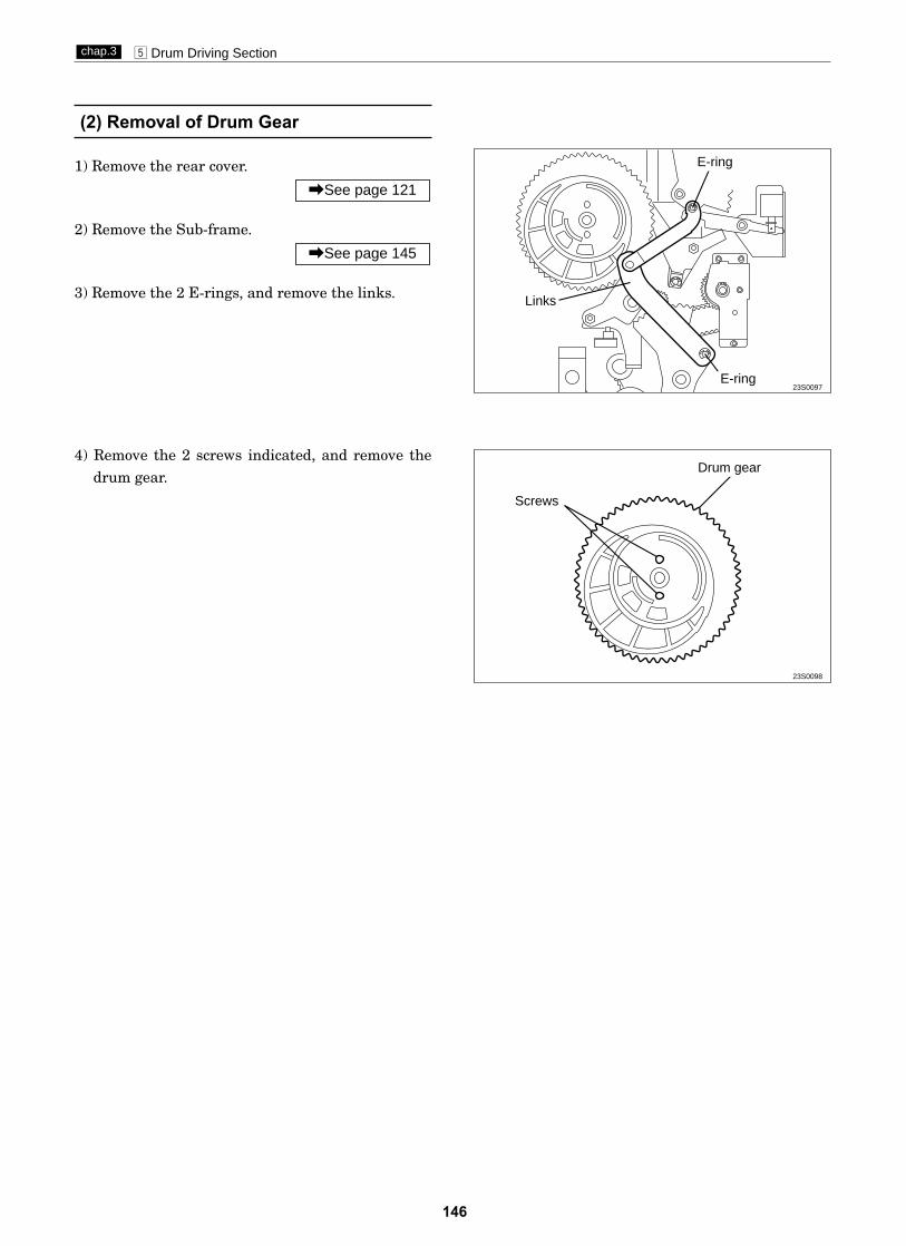
146
b Drum Driving Sectionchap.3
(2) Removal of Drum Gear
1) Remove the rear cover.
2) Remove the Sub-frame.
3) Remove the 2 E-rings, and remove the links.
\See page 145
\See page 121
23S0097
4) Remove the 2 screws indicated, and remove thedrum gear.
23S0098
Links
E-ring
E-ring
Screws
Drum gear

147
n Paper Ejection Sectionchap.3
4) Take out the paper stripper finger and sub paperstripper fingers from the pipe.
Adjust the paper stripper fingerafter it is installed.
IMPORTANT :
n Paper Ejection Section(1) Removal of Paper Stripper Finger /
Sub Paper Stripper Finger
1) Open the master ejection box.2) Remove the set screws.3) Remove the paper stripper finger and sub paper
stripper fingers from the shaft.
Paper stripper finger
Paper stripper finger
Sub paper stripper fingers
Sub paper stripper finger
Pipe
Pipe
Reinstallation
\See page 178

148
n Paper Ejection Sectionchap.3
(2) Removal of Paper Ejection Fan Unit
1) Remove the rear cover.
2) Disconnect the connector.3) Open the front cover, and remove the drum.4) Remove the front cover. 5) Disconnect the connector.6) Open the master ejection box.7) Remove the 2 screws from the cover, and remove
the cover.
\See page 119
\See page 121
8) Remove the 6 screws indicated, and remove thejump plate F/R units.
9) Remove the 4 screws, and pull out the paper ejection fan unit sliding in the direction of anarrow.
23S0099
23S0100
23S0101
CoverScrews
Connector Connector
Jump plate F unit Jump plate R unit
Screws
Screws
Screws
Screws
Paper ejection fan unit
¡Insert the driving shaft coupler to install thepaper ejection fan unit.
Reinstallation
23S0105
Drive shaft coupler(Paper ejection fan unit)

23S0104
23S0103
23S0102
149
n Paper Ejection Sectionchap.3
1) Remove the paper ejection fan unit.
2) Pull the paper ejection belts wider apart toexpose the screws, and secure the belts in thatposition.
3) Remove the 2 screws securing the sensor mounting angle, and remove the angle.
\See page 148
4) Remove the 2 screws from the sensor PCB, andremove the PCB.
Do not lose the 2 spacers.IMPORTANT :
Remove the 2 screws with a driver
Paper ejection belts
Jam sensor
Screws
Spacers
(4) Removal of Jam Sensor (Photo-receivingPCB UNIT)
(3) Removal of Paper Ejection Belt
1) Remove the paper ejection fan unit.
2) Remove the 2 screws from the static removalbrush, and remove the static removal brush.
\See page 148
3) Remove the 2 screws from the ends of the shaft,and remove the shaft.
4) Stretch the belts and install them oriented asshown in the figure.
Screw
Paper ejection belts
Screw
Shaft
Static removal brush
Screws

150
m Drum Sectionchap.3
(1) Removal of Screen
m Drum Section
1) Remove the drum.2) Remove the clamp on the bottom end screen bar
to pull out the screen bar.3) Remove 2 set screws on the top screen bar to pull
out the screen bar.4) Remove the screen from the drum.
Do not rotate the drum reversely.IMPORTANT :
1) Pass the top end screen bar through the screen(top end side).
2) Attach the top end screen bar to the drum.
Do not mistake the bottom end ofthe screen for the top end.
IMPORTANT :
3) Pass the bottom end screen bar through thescreen (bottom end side).
4) Hold the bottom end screen bar in parallel withthe drum and roll it up to the drum rotating thedrum normally.
5) Tighten the screen bar with the clamp.
The stainless screen does not returnto the original state once it is folded.Be careful to handle the screen.
IMPORTANT :
Reinstallation
Screw
Clamp
Screw
Screw
Screen
Top endscreen bar
Bottom endscreen bar
Screw
58mm(top end side)
20mm (bottom end side)
ScreenTop end screen bar
Screw
Bottom end screen bar
Bottom end screen bar
Clamp

151
m Drum Sectionchap.3
(2) Removal of Master Clamp
(3) Removal of Base Unit
1) Remove the screen.
2) Remove 2 screws on the operation side.3) Remove the bearing plate and spring.4) Remove 2 screws on the anti-operation side to
take out the bearing plate.5) Remove the master clamp. The master clamp is
attached to the base with the magnet.
\See page 150
Adjust the master clamp after installation.
\See page 181
IMPORTANT :
1) Remove the master clamp.2) Remove 2 screws, and remove the base unit.
Reinstallation
Screw
Screw
Screw
Screw
Bearing plate
Spring
Master clamp
Base unit

152
m Drum Sectionchap.3
(4) Removal of Outer Frame (Right) Unit
1) Remove the drum.2) Remove 2 screws on the rail and 1 screw on the
stay.3) Remove 3 screws on the outer frame (right) unit
and knob screw.
4) Part the outer frame (right) unit a little andremove 2 connectors.
5) Remove the outer frame (right) unit.
Reinstallation
Do not forget to adjust the railspace after the rail is installed.
\See page 182
IMPORTANT :
ScrewsStay
ScrewScrews
Connector
ConnectorOuter frame (right) unit
Screw
Rail left
Rail right
Outer frame (right) unit
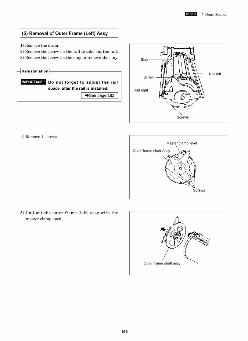
153
m Drum Sectionchap.3
Do not forget to adjust the railspace after the rail is installed.
(5) Removal of Outer Frame (Left) Assy
1) Remove the dram.2) Remove the screw on the rail to take out the rail.3) Remove the screw on the stay to remove the stay.
4) Remove 4 screws.
5) Pull out the outer frame (left) assy with the master clamp open.
Reinstallation
\See page 182
IMPORTANT :
Rail left
Screws
Master clamp lever
Outer frame shaft Assy
Outer frame shaft assy
Stay
Rail right
Screw
Screws

154
m Drum Sectionchap.3
(6) Removal of Inner Frame
1) Remove the outer frame (right) unit.
\See page 152
3) Pull out the inner frame (section inside thedrum) in the direction of an arrow.
Be careful not to damage the druminside.
IMPORTANT :
2) Loosen 2 set screws on the supporting plate,move the supporting plate in the direction ofarrow until it stops and fix it with the screw.
Slide the supporting plate in the direction of arrow1 so that the supporting plate roller, roller unit androller are in contact with the inner surface of theflange right and tighten the roller with the screw,pressing the roller to the inner surface lightly.
Reinstallation
Screws
Supportingplate
Roller unit
Roller
Supporting plate
ScrewsRoller
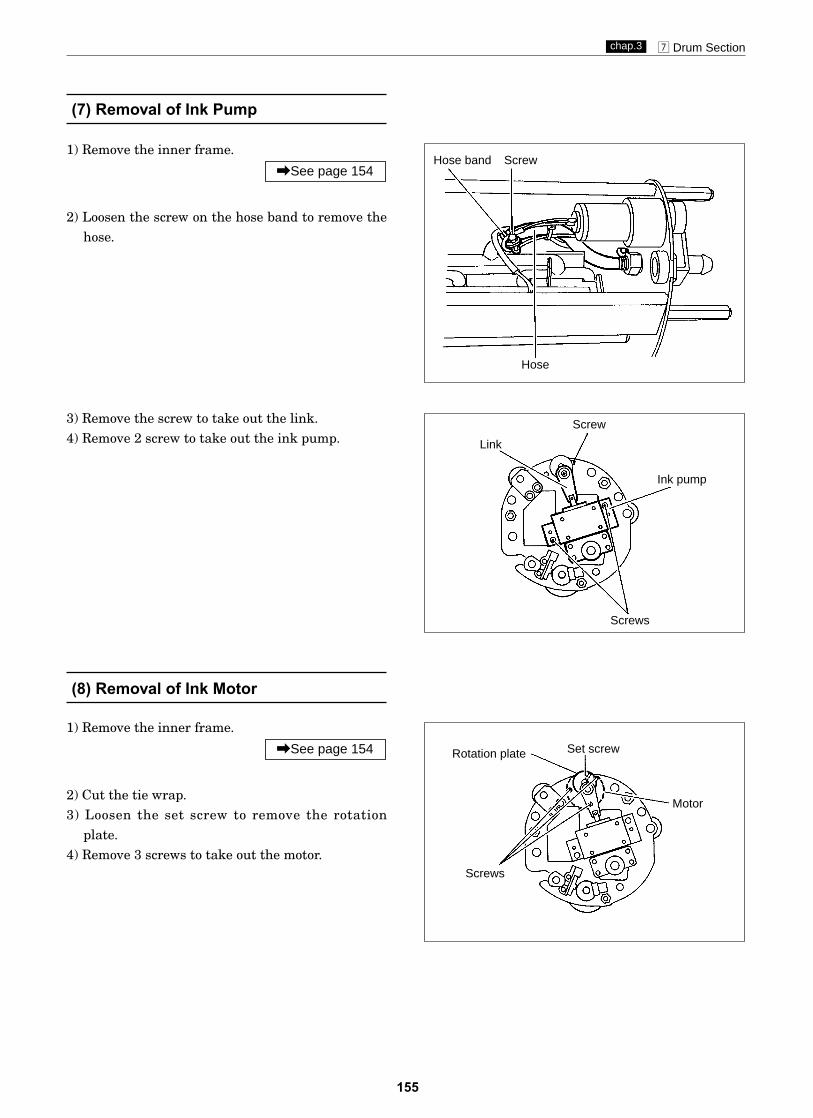
155
m Drum Sectionchap.3
(7) Removal of Ink Pump
(8) Removal of Ink Motor
1) Remove the inner frame.
2) Loosen the screw on the hose band to remove thehose.
\See page 154
3) Remove the screw to take out the link.4) Remove 2 screw to take out the ink pump.
1) Remove the inner frame.
2) Cut the tie wrap.3) Loosen the set screw to remove the rotation
plate.4) Remove 3 screws to take out the motor.
\See page 154
Hose band Screw
Hose
Screw
Link
Ink pump
Screws
Set screwRotation plate
Motor
Screws
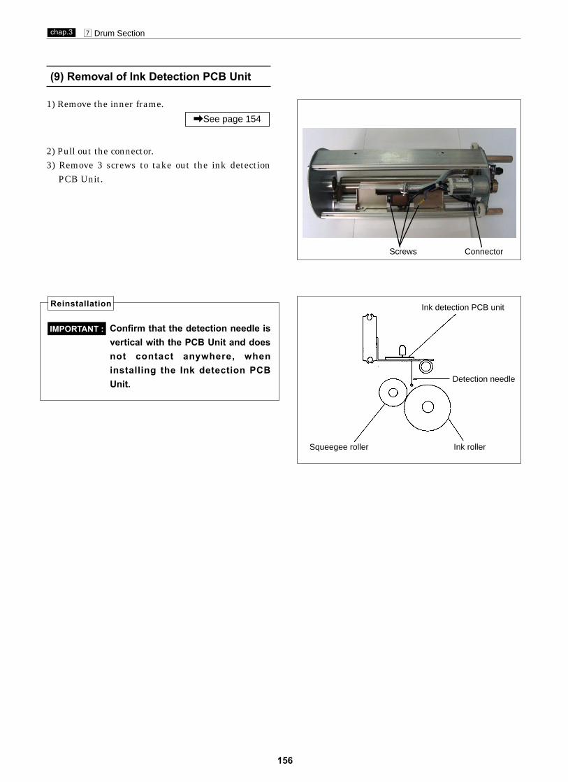
156
m Drum Sectionchap.3
(9) Removal of Ink Detection PCB Unit
Confirm that the detection needle isvertical with the PCB Unit and doesnot contact anywhere, wheninstalling the Ink detection PCBUnit.
IMPORTANT :
Reinstallation Ink detection PCB unit
Ink rollerSqueegee roller
Detection needle
1) Remove the inner frame.
2) Pull out the connector.3) Remove 3 screws to take out the ink detection
PCB Unit.
\See page 154
Screws Connector

157
Chapter 4 Standards / Adjustment
z Scanner Section.........................................................159(1) Attaching the Rear Wire......................................159(2) Attaching the Front Wire.....................................160
x Mastermaking / Master Feed / Ejection Section......161Mastermaking / Master Feed Section ......................161(1) Adjusting the Timing Belt Tension.....................161
Master Ejection Section.........................................162(1) Attaching the Spring............................................162(2) Adjusting the Timing Belt Tension.....................163
Master Clamp opening/Closing Section..............164(1) Adjusting the Timing Belt Tension.....................164(2) Positioning the Master Clamp
Opening / Closing Levers.....................................164(3) Adjusting the A / B / C Modes..............................165
c Paper Feed Section....................................................169(1) Adjusting the Paper Separator
Unit Clearance.....................................................169(2) Adjusting the Paper Separation Pressure...........170(3) Adjusting the Paper Feed Tray
Upper Limit Sensor.............................................170(4) Adjusting the Paper Feed Tray
Lower Limit Switch.............................................171(5) Adjusting the G Roll Escape
Amount / Timing...................................................172(6) Adjusting the Printing margin............................173
v Drum Driving Section................................................174(1) Adjusting the Stop Position.................................174(2) Adjusting the Master Attachment /
Detachment Position ..............................................175
b Press Section............................................................176(1) Adjusting the Press Roll (P Roll) Sensor.............176(2) Adjusting the Printing Area
(Press OFF Timing) ...................................................177
n Paper Ejection Section.............................................178(1) Adjusting the Paper Stripper
Finger Clearance..................................................178
m Drum Section.............................................................179(1) Adjusting the Ink Amount...................................179(2) Adjusting the Squeegee Gap................................180(3) Adjusting the Master Clamp...............................181(4) Adjusting the Master Clamp Section..................181(5) Adjusting the Drum Rail Gap..............................182
DP-M400

158
4
, Electrical System.......................................................183(1) Adjusting Reduction / Enlargement....................183
1. Adjusting the Longitudinal R/E on the Mastermaking Side................................183
2. Adjusting the Longitudinal R/E on the Reading Side...........................................183
(2) Reading Start Position.........................................1841. Adjusting the Top End Reading
Start Position.....................................................1842. Adjusting the Lateral (Operation Side)
Reading Start Position......................................184(3) Adjusting the Mastermaking Start Position.......185
1. When the Scanner Is in Use..............................1852. When in Online..................................................185
(4) Adjusting the Document Reading Darkness.......1861. Adjusting the White Level of the
Document Darkness..........................................1862. Adjusting the Reading Darkness......................187
(5) Adjusting of Printer Unit's Printing Speed.........1881. Pre-stop Speed Adjustment...............................1882. JOG Speed Adjustment.....................................1883. Adjustment of Printing Speeds 1-3...................1894. To Initialize Speed Settings..............................189
(6) Adjusting the End-Mark Sensor1 PCB Unit VR..190
(7) Adjusting the End-Mark Sensor2 PCB Unit VR..190

159
z Scanner Sectionchap.4
(1) Attaching the Rear Wire
Adjustment procedure1) Insert the ball end of the wire into the groove opening
on the pulley. Wrap the wire 6 times in the rear, and 4times on the operation side.
2) Place the wire on the screw side onto the pulley.3) Place the wire on the rear pulley of Slider B.4) Pass the screw through the bracket opening, and fix it
in place with 2 nuts. (There should be a 13mm gapbetween the screw tip and the bracket.)
5) Place the wire on the hook side on the pulley.6) Place the wire on the pulley in front of Slider B.7) Place the wire on the corner guide.8) Place the spring on the hook.
¡For removal of the rear wire \See page 130
NOTE :
zScanner Section
24S040
Fix at 13mm
Ball end
Place on pulley
Wrap 4 times
q
w
y
re
u
i
t
Place on pulley
Place on pulley
Wrap 6 times
Fix with nut
Place on corner guide
Place on spring
Place on pulley

160
z Scanner Sectionchap.4
(2) Attaching the Front Wire
24S041
q
w
y r
e
u
i
t
Ball end
Place on pulley
Wrap 4 times
Place on pulley
Wrap 6 times
Fix with nut
Place on corner guide
Place on pulley
Place on spring
Adjustment procedure1) Insert the ball end of the wire into the groove opening
on the pulley. Wrap the wire 4 times in the rear, and 6times on the operation side.
2) Place the wire on the screw side onto the pulley.3) Place the wire on the front pulley of Slider B.4) Pass the screw through the bracket opening, and fix it
in place with 2 nuts. (There should be a 13mm gapbetween the screw tip and the bracket.)
5) Place the wire on the hook side on the pulley.6) Place the wire on the pulley in rear of Slider B.7) Place the wire on the corner guide.8) Place the spring on the hook.
¡For removal of the front wire \See page 130
NOTE :
Fix at 13mm
Place on pulley

161
x Mastermaking / Master Feed / Ejection Sectionchap.4
xMastermaking / Master Feed / Ejection Section
(1) Adjusting the Timing Belt Tension
Mastermaking / Master Feed Section
Adjust the tension as shown in the figure.1) Apply a force of about 0.6kg in the direction of
the arrow to tension the belt, then tighten theset screw to secure the tension.
2) Apply a force of about 0.5kg in the direction ofthe arrow to tension the belt, then tighten theset screw to secure the tension.
r e
q
t
w
0.6kg
0.5kg
screw
q Tension assy 1
w
e
Clutch 1
r
Angle 1
t
Timing belt 1Timing belt 1
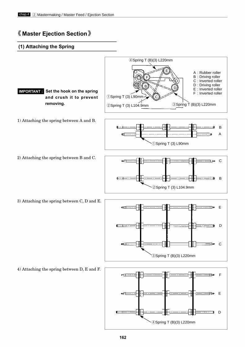
162
x Mastermaking / Master Feed / Ejection Sectionchap.4
(1) Attaching the Spring
Set the hook on the springand crush it to preventremoving.
IMPORTANT :
1) Attaching the spring between A and B.
2) Attaching the spring between B and C.
3) Attaching the spring between C, D and E.
4) Attaching the spring between D, E and F.
Master Ejection Section
A : Rubber rollerB : Driving rollerC : Inverted rollerD : Driving rollerE : Inverted rollerF : Inverted roller
qSpring T (3) L90mm
C
A
B
B
E
D
F
C
E
D
A B
C
D
E
F
rSpring T (B)(3) L220mm
wSpring T (3) L104.9mm
wSpring T (3) L104.9mm
eSpring T (B)(3) L220mm
eSpring T (B)(3) L220mm
rSpring T (B)(3) L220mm
qSpring T (3) L90mm

163
x Mastermaking / Master Feed / Ejection Sectionchap.4
(2) Adjusting the Timing Belt Tension
¡For removal of the master ejection box.
Adjustment procedure1) Loosen the motor's screws.2) Use the motor's screws to adjust the belt's
tension with a force of 0.75kg applied to the tension shaft, as shown in the figure at right.
\See page 136
NOTE :
After adjustment¡Function testing of roll-up motor
1) Access HELP mode H-18.
For basic HELP mode procedures
2) Press and hold down the "down" PRINTING SPEED ADJUSTMENT key. For as long as this key is held down, the roll-up motor will rotate in the reverse direction (counterclockwise), causing the rollers inside the master ejection box to rotate.
3) The motor will stop when the "down" PRINTING SPEED ADJUSTMENT key isreleased.
4) Press the STOP key. The HELP mode menuwill reappear.\ To exit the HELP mode:
Turn the power switch to OFF.\ To select another HELP mode:
Enter the desired HELP mode number using thenumeric keys.
\See page 231
HELP mode H-18 \ see p.252
0.75kg

x Mastermaking / Master Feed / Ejection Sectionchap.4
23S0079
23S0081
23S0082
23S0081
Adjustment procedure1) Loosen the tension set screw.2) Use the set screw to adjust the belt's tension to
about 1kg.
After Adjustment
Be sure to adjust the A/B/C modeafter installation to the printer.
IMPORTANT :
1. Paper feed master clamp opening/closing lever
When tensioning the timing belt, ensure that thesub frame is positioned so that the upper surface ofthe master clamp opening/closing lever is aligned(to within 0.5mm) with the rim of the positioninghole.
2. Paper ejection master clamp opening/closinglever
When tensioning the timing belt, ensure that themaster clamp opening/closing lever is co-centeredwith the sub-frame's positioning holes.
Tension Screws
Position hole Master ejection masterclamp opening/closing lever
Positioning hole
Master feed master clampopening/closing lever
Sub-frame
Positioning hole
Master feed master clamp opening/closing lever
Aligned(to within 0.5mm)
Positioning holeMain frame R
Master ejection master clampopening/closing lever
Master Clamp Opening/Closing Section
(1) Adjusting the Timing Belt Tension
(2) Positioning the Master ClampOpening / Closing Levers
¡For removal of master clamp opening / closing unit.
\See page 138
NOTE :
After Adjustment
Be sure to adjust the A/B/C modeafter installation to the printer.
IMPORTANT :
¡For removal of master clamp opening / closing unit.
\See page 138
NOTE :
¡Paper feed side
¡Paper ejection side
1kg
164

165
x Mastermaking / Master Feed / Ejection Sectionchap.4
uShift
yStop in frontof lever
(3) Adjusting the A / B / C Mode
¡For description of operation.
\See page 76
NOTE :
1. Adjustment for B modeAdjustment procedure1) Remove the drum from the machine body.2) Access HELP mode H-20.
For basic HELP mode procedures.
\See page 231
HELP mode H-20 \ see p.254
3) Press and hold down the "up" PRINTINGSPEED ADJUSTMENT key, until the masterclamp open/close lever moves into the "moreopen than B mode (toward C mode) position"(see right).
4) Turn the power off, then on again.The master clamp switch lever will move into theB mode position and stop there.
5) Turn off the power, and install the drum to themachine body.
6) Open the master ejection box. Then press the JOGswitch (drum rotator switch) to move the masterclamp to a position in front of the open/closelever, and stop it there.
7) Move the master clamp, paying attention to theclearance at the same time.
WARNING¡Do not touch the drum or rolls when operat-
ing the JOG switch.¡Do not put your hands or fingers inside the
machine during operation. They could becaught up or crushed in the machinery,resulting in injury.
B mode
C mode
¡More open than B mode (toward C mode) position
¡When drum is removed from main body (A mode)

166
x Mastermaking / Master Feed / Ejection Sectionchap.4
Standard value
Standard value¡Check that the clearance between the master clamp
lever and master clamp open/close lever is within therange given below.
If the clearance it outside the standard range:1) Turn the fixing screw indicated to move the B
mode shade plate and thereby adjust the clearance.
After adjustmentFollow the procedure below to return to theprevious state.1) Remove the drum.2) Access HELP mode H-20.
For basic HELP mode procedures.
3) Press and hold down the "up" PRINTINGSPEED ADJUSTMENT key, until the masterclamp open/close lever moves into the A modeposition (see right).
4) Turn off the power, and install the drum to themachine body.
\See page 231
HELP mode H-20 \ see p.254
Item
Clearance between masterclamp lever and master clampopen/close lever
1.0 - 1.5mm
¡A mode
Close
Open
B mode sensor (PS4)
B mode shade plate
Fixing screw
A / C mode sensor (PS3)
Master clampopen/close lever
Master clamp lever1.0~1.5mm

167
x Mastermaking / Master Feed / Ejection Sectionchap.4
0.5-1.0mm
2. Adjustment for A and C modes
Before adjustment
A and C mode adjustment must becarried out AFTER B mode adjustment has been completed.
IMPORTANT :
Adjustment procedure1) Remove the drum from the machine body.
2) Access HELP mode H-20.
For basic HELP mode procedures.
\See page 231
HELP mode H-20 \ see p.254
3) Press and hold down the "up" PRINTINGSPEED ADJUSTMENT key, until the masterclamp open/close lever moves into the "moreopen than B mode (toward C mode) position" (seeright).
4) Turn the power off, then on again.The master clamp open/close lever will move intothe B mode position and stop there.
5) Turn off the power, and install the drum to themachine body.
6) Access HELP mode H-09.
7) Press the PRINT key to move the drum to themaster detachment position, and stop it there.
8) Use HELP20 to move the master clamp open/close lever to the C mode position.
HELP mode H-09 \ see p.243
Do not move the master clampopen/close lever towards the Amode position from the B modeposition. Doing so will break themaster clamp.
9) Open the scanner unit.
IMPORTANT :
B mode
C mode
¡More open than B mode (toward C mode) position
¡Stopping drum in master detachment position
¡When drum is removed from main body (A mode)

168
x Mastermaking / Master Feed / Ejection Sectionchap.4
Standard value¡Check that the clearance between the master ejection
box's rubber roller and the master clamp plate iswithin the range given below.
If the clearance is outside the standard range1) Turn the fixing screw indicated to move the A/C
mode shade plate and thereby adjust the clearance. This operation adjusts the clearancefor both the A and C modes.
Do not press the master clamp against the rubber roller.
IMPORTANT :
After adjustmentFollow the procedure below to return to theprevious state.1) Turn the power off, then on again.
The master clamp open/close lever will move intothe B mode position and stop there.
2) Remove the drum.
3) Access HELP mode H-20.
4) Press and hold down the "up" PRINTINGSPEED ADJUSTMENT key, until the masterclamp open/close lever moves into the A modeposition (see right).
5) Turn off the power, and install the drum to themachine body.
HELP mode H-20 \ see p.254
Standard valueItem
Clearance between masterejection box's rubber roller andmaster clamp plate
0.5 - 1.0mm
¡A mode
Close
Open
B mode sensor (PS4)
A / C mode shade plate
A mode sensor (PS3)
Fixing screw
Rubber roller
Master clamp plate
0.5~1.0mm
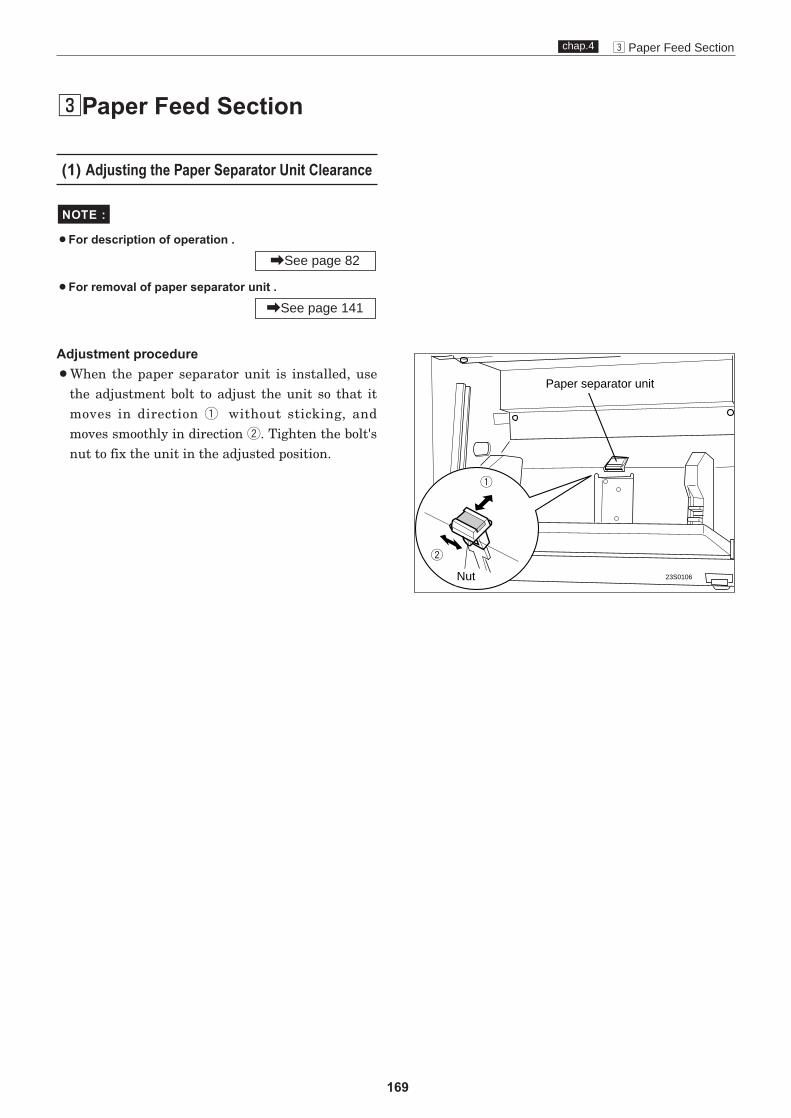
169
c Paper Feed Sectionchap.4
cPaper Feed Section
(1) Adjusting the Paper Separator Unit Clearance
¡For description of operation .
¡For removal of paper separator unit .
Adjustment procedure¡When the paper separator unit is installed, use
the adjustment bolt to adjust the unit so that itmoves in direction q without sticking, andmoves smoothly in direction w. Tighten the bolt'snut to fix the unit in the adjusted position.
\See page 141
\See page 82
NOTE :
Paper separator unit
23S0106
q
w
Nut

170
c Paper Feed Sectionchap.4
(2) Adjusting the Paper Separation Pressure
¡For description of operation .
¡For removal .
Adjustment procedure1) Apply a spring balance as shown at right, then
turn the separation pressure adjust screw sothat the balance reads 140-150g.¡Turning the screw clockwise increases the
pressure.¡Turning the screw counterclockwise decreases
the pressure.
\See page 141
\See page 82
NOTE :
(3) Adjusting the Paper Feed Tray Upper Limit Sensor
¡For description of operation .
Adjustment procedure1) Insert a 1mm thick strip of material between the
paper feed roller and the paper feed inlet.2) Loosen the 2 screws indicated, then adjust the
sensor's position so that the bottom surface ofthe paper feed shaft lever is at the center of thesensor.
3) After adjustment, tighten the screws.
\See page 91
NOTE :
Spring balance140-150g
Paper separationpressure adjust screw
Screw
Paper feed trayupper limit sensor
Screw
1mm thick strip
Position bottomsurface at sensor's
center
43SH0403
23S0225

171
c Paper Feed Sectionchap.4
(4) Adjusting the Paper Feed Tray Lower Limit Switch
¡For description of operation.
¡For removal.
Adjustment method1) Access HELP mode H-02.
For the basic procedure for accessing HELP modes:
2) Press and hold down the "down" PRINTINGSPEED ADJUSTMENT key until the paper feedtray is at its lowermost position. The elevatormotor will run (i.e. the paper feed tray willdescend) for as long as the key is held down.
3) Check that the dimension indicated in the figureat right conforms to the value shown below.
\See page 231
HELP mode H-02 \ see p.236
\See page 140
\See page 92
NOTE :
If the feed length is not the standard value1) Loosen the screws, then adjust the lower limit
switch to a position that yields the standardclearance value.cMoving the sensor in the direction shifts the
lowermost position downward.dMoving the sensor in the direction shifts the
lowermost position upward.
2) After adjustment, tighten the screws.
Standard value
Standard valueItem
Paper feed tray clearance inlower limit position 14mm
23S0109
14mm
ScrewsElevator
lower limit switch
Connector

172
c Paper Feed Sectionchap.4
(5) Adjusting the G Roll Escape Amount /Timing
Adjustment procedure1) Turn the main motor shaft by hand, to move the
escape cam. Stop turning when the bottom of theescape cam reaches the bearing side of theescape lever, so that the cam stops in that position.
2) Loosen the eccentric shaft fixing screw. Thenturn the eccentric shaft to adjust the escapeamount.
¡For description of operation.
Standard value
\See page 86
NOTE :
Standard valueItem
Clearance between escape lever's bearing and escapecam's bolt
2±0.2mm
23S0228
Bearing
2±0.2mm
Eccentricshaft
Screw
Peek through the inspection hole. Escape lever
Escape cam

173
c Paper Feed Sectionchap.4
(6)
¡For description of operation.
NOTE :
\See page 89
Adjustment procedure1) To adjust the Printing margin, position the screws
of the sensor angle's rectangular holes in thecenter of those holes, and fix the screws in thatposition.
4) Adjust the center sensor position to make the Printing margin to 7 ±1mm.
.
Screw
Screw
Center sensor
23S0229
2) Access HELP mode H-30.
HELP mode H-30 \ see p.261
7 ±1mm.
Adjusting the Printing margin
3) Choose test pattern 1 then make master and print.

174
v Drum Drive Unitchap.4
Stopper Groove
JOG switch(DRUM ROTATORswitch)
Drum stop detection edge
(1) Adjusting the Stop Position
vDrum Driving Section
Before adjustment
¡Adjusting the the drum position must be performed AFTER printing speed adjustmentis complete.
Adjustment procedure1) Press and hold down the JOG switch (DRUM
ROTATOR switch). Release the switch when a"beep" tone sounds and the drum stops.
IMPORTANT :
\See page 188
¡For description of operation .
Standard position¡The stop position is correctly adjusted when the
groove in the drum flange is aligned with thestopper.
If the drum is not adjusted to the standard stopposition:Adjust the position of the drum home position /JAM detection sensor so that the stopper fitssmoothly into the groove when the drum is pulledout.[Moving the sensor in this direction makes
stopping occur later.\Moving the sensor in this direction makes
stopping occur earlier.
NOTE :
\See page 96
WARNING¡Do not touch the drum or rolls when operat-
ing the JOG switch.¡Do not put your hands or fingers inside the
machine during operation. They could becaught up or crushed in the machinery,resulting in injury.
23S0232
Screws

175
v Drum Drive Unitchap.4
Item
Advances the stop position
Sets back the stop position
Masterattachment/detachmentposition edge
Open/close lever
Open/close arm
+-1mm
+-1mm
(2) Adjusting the Master Attachment/Detachment Position
¡For description of operation.
1. Master detachment position¡The correct position for stopping of the drum
(position for master detachment) is when the center axis of the master clamp open/close arm and the center axis of the master clamp open/close lever are aligned in a straight line. Adjustso that the offset of the alignment of these two center axes is ±1mm (gauge this value visually).
Adjustment procedure1) Access HELP mode H-09, the drum position
check mode.
NOTE :
4) Loosen the screws indicated, turn the masterattachment/detachment sensor shade plate a little in the direction of the arrows, and provisionally tighten the screws.
5) Repeat step 2), and check the center axis alignment offset.
6) If necessary, repeat steps 2) through 5) until thecenter axis alignment offset is within ±1mm.
7) Properly tighten the screws, and check 6) again.
2. Master attachment position¡Perform adjustment of master attachment
position at the same time as that of master detachment position. Adjust both positions to an accuracy of ±1mm.
Standard value
Offset in alignment of centeraxes of master clampopen/close arm and masterclamp open/close lever
±1mm
\See page 97
HELP mode H-09 \ see p.243
Master attachment position
Open/close arm
Open/close lever
Master detachmentposition
23S0234
23S0235
23S0236
23S0233
Screws

176
b Press Sectionchap.4
Screws
P rollsensor
Bracket
Bracket
About 1mm
(1) Adjusting the of Press Roll (P Roll) Sensor
bPress Section
¡For description of operation.
Adjustment procedure1) Loosen the screw indicated. Then move the
sensor bracket up/down to adjust the press roll so that when it is pushed down to the lowest position by the cam, the distancebetween the bottom of its sensor and the end of the bracket is about 1mm.
NOTE :
\See page 103
23S0238

177
b Press Sectionchap.4
20mm
Rear end of opening
Drum unit
Press roll
Main motor shaft
Drum flange
Mark
Press roll
Screw
Adjust collarHexbolts
Make mark here
(2) Adjusting the Printing Area (Press OFF Timing)
¡For description of operation.
Adjustment procedure1) Make a mark on the end surface of the drum
flange, in a position 20mm forward (in the direc-tion of the forward end) from the rear end of thedrum's opening(hole section).
2) With the press roll activated, turn the mainmotor shaft by hand, and stop turning when thepress roll starts to descend (move in the directionof the arrow).
Standard value¡Open the front cover, and check whether the
center of the press roll is aligned with the mark made in step 1).
NOTE :
Standard valueItem
Alignment of mark on flangeend and center of press roll ±2mm
If the alignment is not correct:1) Loosen the 2 hex bolts indicated.2) Loosen the adjustment collar (eccentric) fixing
screw.3) Turn the adjustment collar (eccentric) to move
the flange and adjust the alignment.Moving the flange upward makes turning off ofthe press occur later \ thereby making theprinting range longerMoving the flange downward makes turning offof the press occur earlier \ thereby making theprinting range shorter
\See page 101
23S0237
23S0246
23S0239

178
n Paper Ejection Sectionchap.4
WARNING¡Do not touch the drum or rolls when
operating the JOG switch.¡Do not put your hands or fingers inside the
machine during operation. They could becaught up or crushed in the machinery,resulting in injury.
Pinch lever
Roller
Lever
Main motor shaft
Paper stripper finger
Drumsurface
(1) Adjusting the Paper Stripper Finger Clearance
nPaper Ejection Section
¡For description of operation.
Adjustment procedure1) With the pinch lever raised up, turn the main
motor shaft. Stop turning when the lever's rolleris positioned at the bottom of the paper stripperfinger cam.
NOTE :
Standard value¡Check that the clearance between the drum
surface and the paper stripper finger conformsto the value shown below.
If the clearance is not the standard value:1) Loosen the screw indicated and use the stopper
to adjust the clearance to the standard value.Then retighten the screws.
After adjustment:
¡After adjustment, press the JOG switch (DRUMROTATOR switch) to return the drum to itshome position.
IMPORTANT :
Standard valueItem
Clearance between drum sur-face and tip of paper stripperfinger
0.5mm~1mm
\See page 105
23S0240
23S0247
0.5mm~1mm
Screw

179
m Drum Sectionchap.4
Adjusting the ink adjusting knob
¡For removal.
NOTE :
mDrum Section
(1) Adjusting the Ink Amount
Adjustment procedure1) When printed too dark or too light on the
operation side:• Too dark: switch in the (-) direction
(3 settings)• Too light: switch in the (+) direction
(3 settings)
2) When printed too dark or too light on the rearside:• Too dark: switch in the (-) direction
(3 settings)• Too light: switch in the (+) direction
(3 settings)3) When printed too dark or too light on the entire
surface:• Adjust the above 1) and 2) at the same time.
There are 7 settings, standard and±3 settings to adjust the printingdarkness. Print more than tensheets every time the printingdarkness is switched by one settinguntil the most desirable printingdarkness is obtained.Repeat the above procedures untilthe most desirable printing darknessis obtained.
IMPORTANT :
Ink adjusting knob on therear side
Ink adjusting knob on theoperation side
Do not loosen set screw
¡Ink adjusting knob on the operation side (standard position)
Too dark
Too light
\See page 150
Too dark
Too light
Do not loosen set screw
¡Ink adjusting knob on the rear side (standard position)

180
m Drum Sectionchap.4
(2) Adjusting the Squeegee Gap
¡For removal.
Adjustment procedure¡The gap between the squeegee and the ink roller
is adjusted as shown in the figure when the inkamount is based on the standards.If the ink amount does not meet the standards,adjust it as follows:-
NOTE :
If the clearance is not the standard value1) 2 set screws 1 are used in one place. Remove one
set screw 1 and loosen the other one. Perform thesame operation for both sides. Be careful not tolose the removed set screws.
2) Loosen set screws 2 on both sides.
3) Adjust the gap with the adjusting screws on bothsides so that the space on both sides meets thestandards.
After adjustment1) Tighten set screw 2.
2) Tighten set screw 1.
3) Check the gap again after the ink amount adjusting knob is moved several times in thedirection + or -.
4) If the gap is proper, attach set screw 1 and tighten it to fix.
Squeegee
Gap
Ink roller
Squeegee
Ink roller
Set screw 2
Set screw 1
¡Operation side
Adjustingscrew
Set screw 2
Set screw 1
Adjusting screw
Ink adjusting knob
\See page 150
Ink adjusting knob
¡Rear side
Standard valueItem
Clearance between squeegeeand ink roller 0.03±0.005mm
Standard value
0.03±0.005mm

181
m Drum Sectionchap.4
(3) Adjusting the Master Clamp
¡For removal.
When the master clamp parallelism is not proper,the master creases. When the master clamp is notflat, the master is easily removed and creases.* Adjust the master clamp with the set screw on theoperation side.
1. Adjusting the clamp parallelismAdjustment procedure1) Loosen the set screws on the clamp plate and
shaft to adjust the parallelism.
NOTE :
Loosen the set screw on theoperation side to adjust.But do not loosen the set screw onthe lever shaft.
IMPORTANT :
2. Adjusting the clamp flatnessAdjustment procedure
1) Cut the master, leaving 20mm wide piece atthree places, both sides and center. Have theclamp plate grip the three sections.
2) When the resistance for pulling the master outis not stable, rotate the clamp screw to adjust.
(4) Adjusting the Master Clamp Section
Adjustment procedure1) Adjust with HELP mode 29 so that the clamp
amount of the master (A section in the figure) is0~3mm with the master attached.
2) After HELP 29 adjustment, press the master setswitch and perform master set movement once.(Be sure to remove all paper scraps.) Then perform Mastermaking, and check the gripper margin.
Set screws
Clamp plate
Clamp plate
Clamp plate
Rubber magnet Torsion
Master20mm
Master Master
Operation sideLever shaft
Set screws (for adjustment)
shaft\See page 150
20mm 20mm
HELP mode H-29 \ see p.262
Master clamp
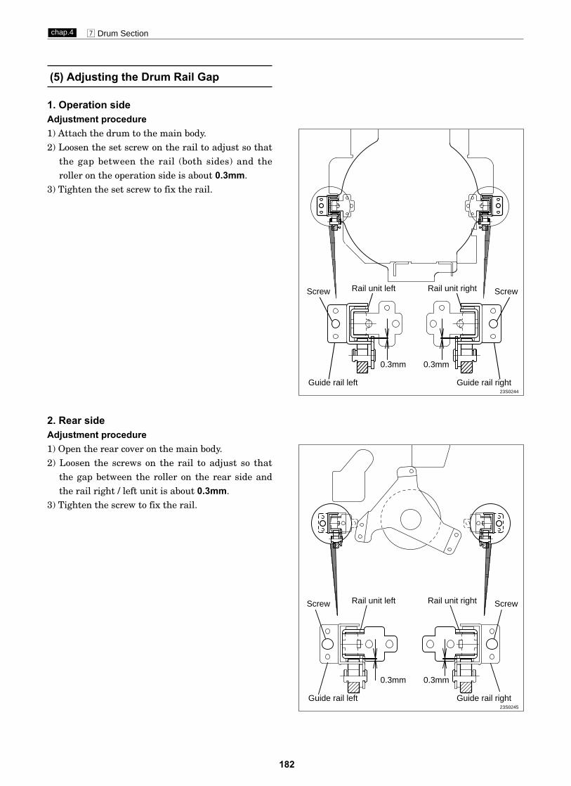
182
m Drum Sectionchap.4
(5) Adjusting the Drum Rail Gap
1. Operation sideAdjustment procedure1) Attach the drum to the main body.2) Loosen the set screw on the rail to adjust so that
the gap between the rail (both sides) and theroller on the operation side is about 0.3mm.
3) Tighten the set screw to fix the rail.
2. Rear sideAdjustment procedure1) Open the rear cover on the main body.2) Loosen the screws on the rail to adjust so that
the gap between the roller on the rear side andthe rail right / left unit is about 0.3mm.
3) Tighten the screw to fix the rail.
Guide rail left Guide rail right
0.3mm0.3mm
Rail unit left ScrewScrew Rail unit right
23S0244
Guide rail left Guide rail right
0.3mm0.3mm
Rail unit left ScrewScrew Rail unit right
23S0245

183
, Electrical systemchap.4
(1) Adjusting Reduction / Enlargement
1. Adjusting the Longitudinal R / E on theMastermaking Side
Adjustment procedure1) Set the HELP mode.
Turn the power on with the PRINTING SPEEDADJUSTMENT keys and held down.
2) Set to H-30 (Test pattern printing mode). Pressthe PRINT key with the 3 and 0 keys helddown.
3) Set the master darkness to NORMAL, performMastermaking and print paper*. No need to placethe document.*DP-M420 : print B4 paper*DP-M400/410 : print A4 paper
Standard values:¡Check that A section of the printed test pattern is
200 ± 0.5mm.
If the clearance is not the standard value:1) If not, adjust with the H-22.
HELP mode H-22 \ see p.255
Adjustment procedure1) Prepare a basic document as shown in the figure.
Draw a line (main-scanning direction) at theposition 30mm from the top end of the paper*and at the position 200mm from the above line.*DP-M420 : print B4 paper*DP-M400/410 : print A4 paper
2) Place the document on the document table to perform mastermaking and printing.
Standard values:¡Compare the size of A section of the printed
image with that of the basic document. Checkthat the difference of the size is ±2.0 mm.
If the clearance is not the standard value:1) If not, adjust with the H-24.
HELP mode H-24 \ see p.257
Center of the paper
,Electrical system
23S0312
¡Test pattern 2
HELP mode H-30 \ see p.263
2. Adjusting the Longitudinal R / E on theReading Side
Adjust the longitudinal R / E on thereading side after the longitudinal R/ E on the Mastermaking side.
IMPORTANT :
Before adjustment
HELP mode H-24 ADF \ see p.257
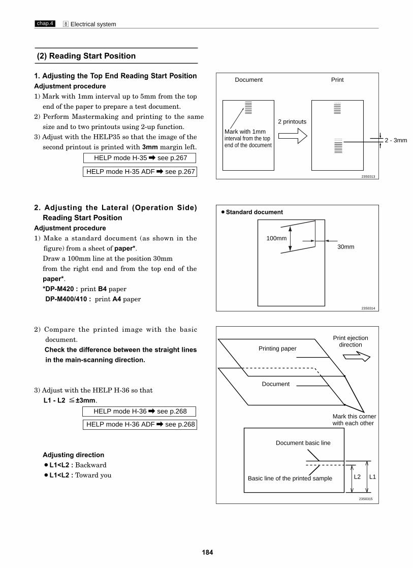
184
, Electrical systemchap.4
(2) Reading Start Position
1. Adjusting the Top End Reading Start PositionAdjustment procedure1) Mark with 1mm interval up to 5mm from the top
end of the paper to prepare a test document.2) Perform Mastermaking and printing to the same
size and to two printouts using 2-up function.3) Adjust with the HELP35 so that the image of the
second printout is printed with 3mm margin left.
HELP mode H-35 \ see p.267
2. Adjusting the Lateral (Operation Side)Reading Start Position
Adjustment procedure1) Make a standard document (as shown in the
figure) from a sheet of paper*.Draw a 100mm line at the position 30mmfrom the right end and from the top end of thepaper*.*DP-M420 : print B4 paper*DP-M400/410 : print A4 paper
2) Compare the printed image with the basic document. Check the difference between the straight linesin the main-scanning direction.
3) Adjust with the HELP H-36 so thatL1 - L2 ±3mm.
Adjusting direction¡L1<L2 : Backward¡L1<L2 : Toward you
HELP mode H-36 \ see p.268
¡Standard document
30mm100mm
Mark with 1mminterval from the topend of the document
Mark this cornerwith each other
Document basic line
L2 L1
Document
Printing paper
Print ejectiondirection
Basic line of the printed sample
2 printouts
Document
23S0313
23S0314
23S0315
HELP mode H-35 ADF \ see p.267
HELP mode H-36 ADF \ see p.268
2 - 3mm

Adjustment procedure1) Perform mastermaking and printing of the online test pattern. Adjust with the HELP mode, H-16 so that
the basic line is positioned ± 3mm from the top end of the paper.
185
, Electrical systemchap.4
(3) Adjusting the Mastermaking Start Position
¡Adjust the Mastermaking start position when in online after the printing position sensor and master attachment / detachment position are adjusted.\See page 175
\See page 173
¡Adjust the Mastermaking start position with the scanner in use after the printing position sensor, master attachment / detachment position and top end reading start
position are adjusted.
\See page 175\See page 173
IMPORTANT :
Adjustment procedure1) Set the printing position (top and bottom direction)
to the standard.2) Draw a line at the position 30mm from the top
end of the document and prepare a basic documentas shown in the figure.
3) Compare the processed image with the basic document.Check the difference of the lines inthe sub-scanningdirection.
4) Adjust with the HELP mode, H-37 so thatL1 - L2 ± 3mm.
Adjusting direction¡L1<L2 : Upward¡L1>L2 : Downward
HELP mode H-37 \ see p.269
¡Standard document
HELP mode H-16 \ see p.250
Mark this corner with each other
Document basic line
L2
L1
Document
Printing paper
Print ejection direction
Basic line of theprinted sample
23S0316
23S0317
Draw a line at the position 30mmfrom the top end of the document
1. When the Scanner Is in Use
Before adjustment
2. When in Online
IMPORTANT :
\See page 184
Before adjustment
HELP mode H-37 ADF \ see p.269

186
, Electrical systemchap.4
(4) Adjusting the Document Reading Darkness
¡For description of operation.
1. Adjusting the White Level of the DocumentDarkness
The basic darkness of the document (lightness ofthe white section of the document = white level) isdetected by reading the document darkness. If thewhite level is not proper, printed surface gets dirtyor the light section of the document is not processedfor Mastermaking.
NOTE :
\See page 55
Adjusting the White Level
1) Call the HELP mode.Take the following procedures for adjustment:-
1. Text mode: H-33
2. Photograph mode: H-26
2) Input the correction value on the keypad, "0" or "1".¡When the processed document gets dirty :
"0 1 1 1" The white level is corrected down.
¡When the thin section of the document is notprocessed for Mastermaking :"1 1 1 1" The white level is corrected up.
3) Press the = key to memorize the correctionvalue.
4) Perform Mastermaking and printing to check thedarkness.
HELP mode H-26 \ see p.259
HELP mode H-33 \ see p.266
¡In the normal state
¡When the white level is too high:
¡When the white level is too low:
the section is printed dirty
the section is not processed for Mastermaking
Sign flag
A : 0 B : 1 C : 1 D : 1
Sign flag
A : 1 B : 1 C : 1 D : 1
Correction amount display
Correction amount display
¡HELP mode H-33/26 display
HELP mode H-33 ADF \ see p.266
HELP mode H-26 ADF \ see p.259

2. Adjusting the Reading DarknessAdjustment procedureAdjust the document reading darkness in
Mastermaking as follows:1) Help mode
Text mode : H-50
Photograph mode : H-23
2) Input the correction value on the keypad, "1" or"0" (Sign flag / Collection amount display).
3) Press the = key to memorize the correctionvalue
4) Perform Mastermaking and printing to check thedarkness.
• When adjusted with the H-23 by one stage, thestandard position on the control panel changesto 3/8 stage as follows : -
HELP mode H-23 \ see p.256
HELP mode H-50 \ see p.275
187
, Electrical systemchap.4
dark
light
H-50, H-23: [0001]
H-50, H-23: [0001]
Adjusting the Mastermaking darknesson the control panel
Normal
dark
light
dark
light
Normal
23S0318
Sign flag
A : 1 B : 1 C : 1 D : 1
Correction amount display
¡HELP mode H-50/23 display
HELP mode H-50 ADF \ see p.275
HELP mode H-23 ADF \ see p.256

188
, Electrical systemchap.4
Pre-stop speed
¡HELP mode H-01 display
JOG speed
¡HELP mode H-01 display
(5) Adjusting of Printer Unit's Printing Speed
1. Pre-stop Speed AdjustmentAdjustment procedure1) Access HELP mode H-01.
For basic HELP mode procedures.
2) Press the DOCUMENT MODE SWITCH key repeatedly, to select PHOTOGRAPH.
3) Check the speed value displayed. The value should be4-6rpm.
If the value is not correct:¡Press the "PRINTING POSITION ADJUSTMENT "keys
to adjustment the speed.
4) Press the STOP key. The new (adjusted) value willbe memorized, and the HELP mode menu will reappear.
HELP mode H-01 \ see p.234
\See page 231
2. JOG Speed AdjustmentAdjustment procedure1) Access HELP mode H-01.
For basic HELP mode procedures.
2) Press the DOCUMENT MODE SWITCH key repeatedly, to select TEXT/PHOTOGRAPH.
3) Check the speed value displayed. The value should be16rpm.
If the value is not correct:¡
4) Press the STOP key. The new (adjusted) value willbe memorized, and the HELP mode menu will reappear.
HELP mode H-01 \ see p.234
\See page 231
1 1 1 r p m
1 1 1 r p m
Press the "PRINTING POSITION ADJUSTMENT "keysto adjustment the speed.
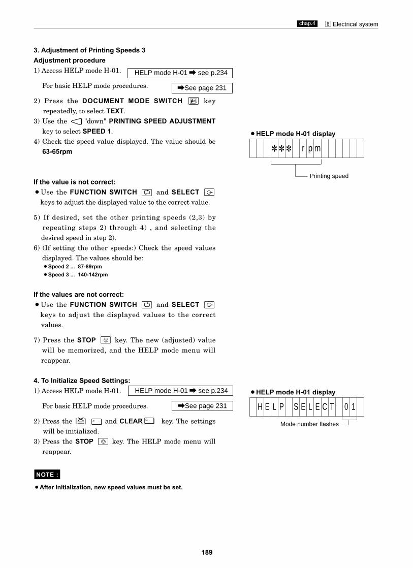
189
, Electrical systemchap.4
¡HELP mode H-01 display
3. Adjustment of Printing Speeds 3Adjustment procedure1) Access HELP mode H-01.
For basic HELP mode procedures.
2) Press the DOCUMENT MODE SWITCH key repeatedly, to select TEXT.
3) Use the "down" PRINTING SPEED ADJUSTMENTkey to select SPEED 1.
4) Check the speed value displayed. The value should be63-65rpm.
If the value is not correct:¡Use the FUNCTION SWITCH and SELECT
keys to adjust the displayed value to the correct value.
5) If desired, set the other printing speeds (2,3) by repeating steps 2) through 4) , and selecting the desired speed in step 2).
6) (If setting the other speeds:) Check the speed valuesdisplayed. The values should be:¡Speed 2 ... 87-89rpm¡Speed 3 ... 140-142rpm
If the values are not correct:¡Use the FUNCTION SWITCH and SELECT
keys to adjust the displayed values to the correct values.
7) Press the STOP key. The new (adjusted) value will be memorized, and the HELP mode menu will reappear.
4. To Initialize Speed Settings:1) Access HELP mode H-01.
For basic HELP mode procedures.
2) Press the [=] and CLEAR key. The settingswill be initialized.
3) Press the STOP key. The HELP mode menu willreappear.
¡After initialization, new speed values must be set.
NOTE :
C
HELP mode H-01 \ see p.234
\See page 231
HELP mode H-01 \ see p.234
\See page 231
¡HELP mode H-01 display
Mode number flashes
H E L P S E L E C T 0 1
Printing speed
1 1 1 r p m

190
Adjusting the End-Mark Sensor1 PCB Unit VR
1) Rotate the VR1 on the end mark sensor1 PCBUnit in the counterclockwise direction (CCW) asfar as it stops.
2) Call HELP mode, H-13 to read the value.(About 63 when master is not set)
3) Rotate the VR1 on the end mark sensor1 PCBUnit to adjust so that the value of HELP modeH-13 is value from 60-63 when master is not set,
End-Mark Sensor1 PCB Unit
Adjusting the End-Mark Sensor2 PCB Unit VR
1) Rotate the VR1 on the end mark sensor2 PCBUnit in the counterclockwise direction (CCW) asfar as it stops.
2) Call HELP mode, H-13 to read the value.
3) Rotate the VR1 on the end mark sensor2 PCBUnit to adjust so that the value of HELP modeH-13 is value from 0-10 when white mark is under ,
End-Mark Sensor2 PCB Unit
(6)
(7)
or the value from 50-63 when black mark is under.
white master is set.(Reference to page.68.)master) is set,and the value is from 0-10 when and the value is from 40-55 when end mark(black
VR 1CN 1
VR 1CN 1

191
z DUPRINTER Installation Instructions.....................1921. Before Installation..................................................1922. Installation Instructions.........................................192
(1) Unpacking Checks............................................192(2) Assembly ...........................................................193(3) Power Switch ON ..............................................195(4) Setting the Master Roll ....................................196(5) Preparation of Drum .........................................198(6) Setting the Ink Pack .........................................200(7) Supplying Ink and Adjusting Ink Amount ......201(8) If Option are Installed ......................................201
5
Chapter 5 Installation

z DUPRINTER Installation Instructionschap.5
192
zDUPRINTER InstallationInstructions
1. Before Installation :
Safety precautions¡The precautions below are vital for safety and must
be taken.
2. Installation Instructions
(1) Unpacking Checks
q Packages for 1 complete DUPRINTER:
DP-M420• 1 printer unit package (product name: DP-M420
DP-M410• 1 printer unit package (product name: DP-M410)
Check that the above 3 packages are present.
w Unpack the package.
Carry out unpacking in a placethat is safe for the work.
IMPORTANT :
e Contents checks for each package.Check that the packages have the contents listedbelow.
•Printer unit package
If the optional printer stand is used, install it nowby referring to the instructions on the followingpage. \See page 194
WARNING
¡Do not use a source voltage otherthan that specified. Do not connectmultiple loads to a single outlet.Fire or electrical shock can result.
¡Do not place the machine in anunstable position, such as on anunsteady support or sloping area.If the machine drops or falls over, aperson could get injured.
¡Do not place the machine in a humidor dusty area. Fire or electrical shock can result.
¡When the DUPRINTER is installed tothe printer stand, lock the casters.Otherwise the equipment couldmove or fall over, causing injury.
¡To move the equipment, push onthe printer stand. Pushing on theDUPRINTER is dangerous andcould make the equipment fallover.
If the optional printer stand is used:
¡Use only the power cord that is provided among the accessories.Insert the power cord plug firmlyinto the socket, so that proper electrical contact is effected.
aUse of any other power cord couldresult in imperfect grounding.If grounding is imperfect and electrical leakage occurs, fire or electric shock could result.
)
Item Quantity
Printer unit proper 1
Installation manual 1
Operation Manual 1
Warranty 1
Master ejection core 1
Power cord 1
Print Tray 1
Master holder 2
DP-M400• 1 printer unit package (product name: DP-M400)
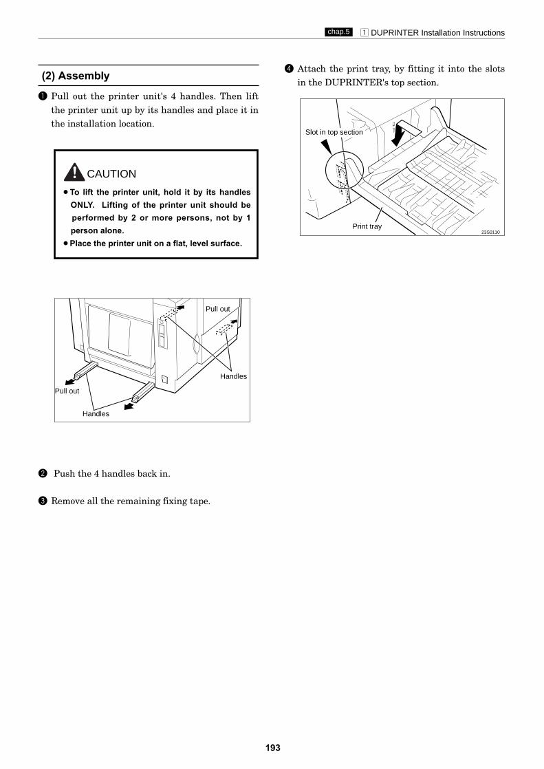
z DUPRINTER Installation Instructionschap.5
193
(2) Assembly
q Pull out the printer unit's 4 handles. Then liftthe printer unit up by its handles and place it inthe installation location.
w Push the 4 handles back in.
e Remove all the remaining fixing tape.
23S0110
r Attach the print tray, by fitting it into the slotsin the DUPRINTER's top section.
Handles
Handles
Pull out
Pull out
Slot in top section
Print tray
CAUTION
¡To lift the printer unit, hold it by its handlesONLY. Lifting of the printer unit should be performed by 2 or more persons, not by 1 person alone.
¡Place the printer unit on a flat, level surface.

z DUPRINTER Installation Instructionschap.5
194
q Unpacking Check.2Check that the printer stand unit package is
present.w Unpack the printer stand unit package.
e Check that the package has the contents listedbelow.
r Assemble the printer stand unit.t Place the printer stand unit on a flat, level
surface.y Lock the printer stand unit's casters.u Pull out the printer unit's 4 handles.
i Lift up the printer unit by its handles, andmount it onto the printer stand unit so that itsrubber feet mate into the recesses in theprinter stand.
o Push the 4 handles back in.
!0 Remove all the remaining fixing tape.
!1 Attach the print tray, by fitting it into the slotsin the DUPRINTER's bottom section.
Carry out unpacking and assmblyin a place that is safe for the work.
IMPORTANT :
* Check the unit's casters for abnormality.
23S0027
23S0111
Pull out
RecessesRecesses
Handle Handle
Runner feet
Slot in bottom section
Print tray
CAUTION
¡To lift the printer unit, hold it by its handlesONLY. Lifting of the printer unit should be performed by 2 or more persons, not by 1 person alone.
Item Quantity
Printer stand unit 1
Using the optional printer stand
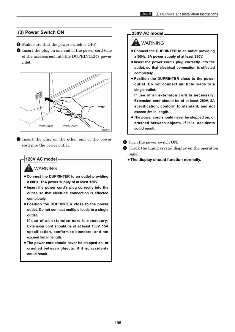
z DUPRINTER Installation Instructionschap.5
195
q Make sure that the power switch is OFF.w Insert the plug on one end of the power cord (one
of the accessories) into the DUPRINTER's powerinlet.
e Insert the plug on the other end of the powercord into the power outlet.
WARNING
¡Connect the DUPRINTER to an outlet providinga 60Hz, 15A power supply of at least 120V.
¡Insert the power cord's plug correctly into theoutlet, so that electrical connection is effectedcompletely.
¡Position the DUPRINTER close to the poweroutlet. Do not connect multiple loads to a singleoutlet.If use of an extension cord is necessary:Extension cord should be of at least 130V, 15Aspecification, conform to standard, and notexceed 5m in length.
¡The power cord should never be stepped on, orcrushed between objects. If it is, accidentscould result.
120V AC model
(3) Power Switch ON
WARNING
¡Connect the DUPRINTER to an outlet providinga 50Hz, 8A power supply of at least 230V.
¡Insert the power cord's plug correctly into theoutlet, so that electrical connection is effectedcompletely.
¡Position the DUPRINTER close to the poweroutlet. Do not connect multiple loads to asingle outlet.If use of an extension cord is necessary:Extension cord should be of at least 250V, 8Aspecification, conform to standard, and notexceed 5m in length.
¡The power cord should never be stepped on, orcrushed between objects. If it is, accidentscould result.
r Turn the power switch ON.t Check the liquid crystal display on the operation
panel.¡The display should function normally.
230V AC model
23S0010
Power cordPower inlet

z DUPRINTER Installation Instructionschap.5
196
(4) Setting the Master Roll
q Press the scanner switch and open the scanner.
Scanner switch
w
e
Master holder
Take out a new master roll from the bag.Insert the master holders deeply into both ends of the master roll. (Holders are interchangeable.)
Insert the master roll into the machine
so that the ID mark line on the roll is facing
the control panel.
r
t
Peel off the seal.
Pull out the master and insert the fronthead of the master until it contacts the roller.
•If the master is not pulled in ,then gently press in as far as possible to set again.
SEAL
IMPORTANT
y Push the THERMAL HEAD ESCAPE LEVER.The master will be pulled in, and cut auto-matically.If the master does not enter, pull the master back.
THERMAL HEADESCAPE LEVER
Scanner unit

z DUPRINTER Installation Instructionschap.5
197
u
¡¡If the master is wrinkled:push down the
thermal head escape lever 2 or 3 times.¡¡The cutter operates and stops after the
master is cut.Remove the cut piece left inside themachine.
Remove the trimmed piece of the master.
Gently close the document receiving tray.i
IMPORTANT
¡¡When the master stops, make sure thatyou remove the trimmed piece of themaster.
IMPORTANT
Scanner unit

23S0017
23S0018
23S0019
z DUPRINTER Installation Instructionschap.5
198
(5) Preparation of Drum
WARNING
¡Do not touch the drum or rollers when youoperate the jog switch.
¡Do not put hands inside machine while it isoperating.Hands could get caught up or crushed.
q Press the jog switch (drum rotator switch).Hold down until the drum stops with a beep.
w Open the front cover toward you.
e Lift up the drum securing lever.While lifting the lever up, pull out the drumhandle toward you, pulling it straight out until itstops.
CAUTION
¡Hold the drum level and place it on a flat,solid surface.
¡The stainless screen does not return to theoriginal state once it is folded. Be careful tohandle the screen.
r Grip the upper drum shaft with your other hand,and pull the drum out toward you while slightlylifting the near end of the drum.
Upper drum shaft
t Move the lever with a hand to open and close themaster clamp once or twice.
y Hold the drum level and place the drum guideroller onto the rail in the machine.
Rail
Master clamp
Roller
Drum
23S0014
Jog switch
q
w
e
Front cover
Drum securing leverDrum handle
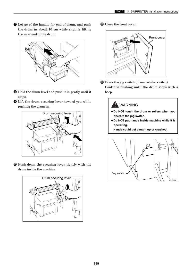
z DUPRINTER Installation Instructionschap.5
199
u Let go of the handle far end of drum, and pushthe drum in about 10 cm while slightly liftingthe near end of the drum.
i Hold the drum level and push it in gently until itstops.
o Lift the drum securing lever toward you whilepushing the drum in.
!0 Push down the securing lever tightly with thedrum inside the machine.
!1 Close the front cover.
WARNING
¡Do NOT touch the drum or rollers when youoperate the jog switch.
¡Do NOT put hands inside machine while it isoperating.Hands could get caught up or crushed.
!2 Press the jog switch (drum rotator switch).Continue pushing until the drum stops with abeep.
23S0014
Jog switch
Drum securing lever
Drum securing lever
Front cover
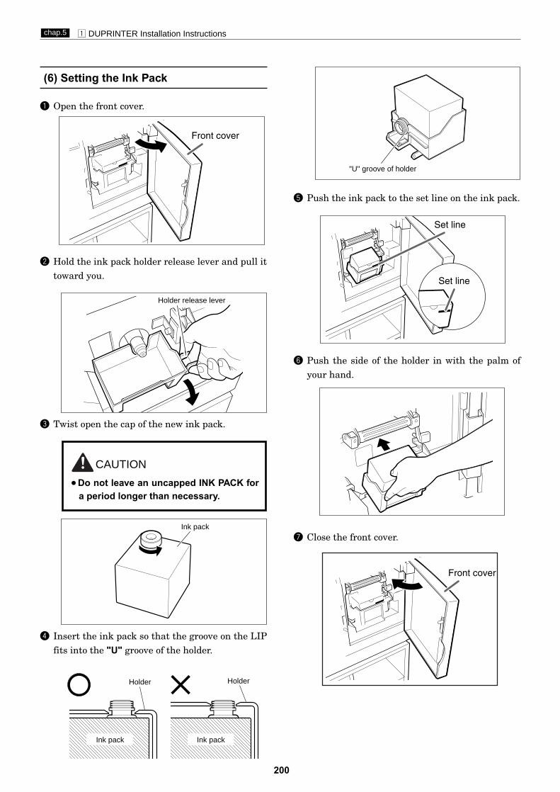
z DUPRINTER Installation Instructionschap.5
200
(6) Setting the Ink Pack
q Open the front cover.
w Hold the ink pack holder release lever and pull ittoward you.
e Twist open the cap of the new ink pack.
CAUTION
¡Do not leave an uncapped INK PACK fora period longer than necessary.
r Insert the ink pack so that the groove on the LIPfits into the "U" groove of the holder.
Ink pack
Holder Holder
Ink pack
Holder release lever
Ink pack
t Push the ink pack to the set line on the ink pack.
y Push the side of the holder in with the palm ofyour hand.
u Close the front cover.
"U" groove of holder
Front cover
Set line
Set line
Front cover
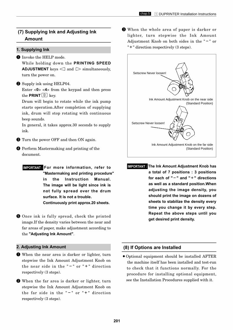
z DUPRINTER Installation Instructionschap.5
201
(7) Supplying Ink and Adjusting InkAmount
(8) If Options are Installed
q Invoke the HELP mode.While holding down the PRINTING SPEEDADJUSTMENT keys and simultaneously,turn the power on.
w Supply ink using HELP04.Enter <0> <4> from the keypad and then pressthe PRINT key.Drum will begin to rotate while the ink pumpstarts operation.After completion of supplyingink, drum will stop rotating with continuousbeep sounds.In general, it takes approx.30 seconds to supplyink.
e Turn the power OFF and then ON again.
r Perform Mastermaking and printing of thedocument.
For more information, refer to"Mastermaking and printing procedure"in the Instruction Manual.The image will be light since ink isnot fully spread over the drum surface. It is not a trouble. Continuously print approx.20 sheets.
IMPORTANT :
t Once ink is fully spread, check the printedimage.If the density varies between the near andfar areas of paper, make adjustment according tothe "Adjusting Ink Amount".
e When the whole area of paper is darker orlighter, turn stepwise the Ink AmountAdjustment Knob on both sides in the "4" or"3" direction respectively (3 steps).
2. Adjusting Ink Amount
Setscrew Never loosen!
Setscrew Never loosen!
Ink Amount Adjustment Knob on the near side(Standard Position)
Ink Amount Adjustment Knob on the far side(Standard Position)
1. Supplying Ink
q When the near area is darker or lighter, turnstepwise the Ink Amount Adjustment Knob onthe near side in the "4" or "3" directionrespectively (3 steps).
w When the far area is darker or lighter, turnstepwise the Ink Amount Adjustment Knob onthe far side in the "4" or "3" directionrespectively (3 steps).
The Ink Amount Adjustment Knob hasa total of 7 positions : 3 positionsfor each of "4" and "3" directionsas well as a standard position.Whenadjusting the image density, youshould print the image on dozens ofsheets to stabilize the density everytime you change it by every step.Repeat the above steps until youget desired print density.
IMPORTANT :
¡Optional equipment should be installed AFTERthe machine itself has been installed and test-runto check that it functions normally. For the procedure for installing optional equipment,see the Installation Procedures supplied with it.

202
MEMO

203
z Guaranteed Periodical Maintenance.......................204x Cleaning and Oiling..................................................204
(1) Cleaning ...............................................................(2) Oiling ....................................................................
c Periodical Maintenance............................................205(1) 6-month Periodical Checking ..............................(2) Criteria for Replacing the Primary Parts ...........
6
Chapter 6 Maintenance/Check
204
204
205
205

z Guaranteed Periodical Maintenance x Cleaning and Oilingchap.6
204
zGuaranteed PeriodicalMaintenance
(1) Cleaning
•The serviceman will visit the user periodically after delivery. The maintenance operation described in theperiodical maintenance list is performed and instructs how to follow the operation.When the serviceman is called by telephone, the following maintenance must be performed after clearingthe trouble.
1. Cleaning the document.2. Cleaning the document table glass.3. Cleaning the thermal head.
xCleaning and Oiling
1.Paper shreds:Clean with a brush or dry cloth.Clean the mirror and reflection plate in the scanner section with a blower brush.
2.Ink:Clean with soap.Oil or grease after ink or paper shreds are removed.
(2) Oiling
2.Gear section:Grease the gear section after removing paper shreds on the bottom of gear.
1.Bearing section:Oil the edge surface and bearing sections with oiler, rotating the lever and roller.

c Periodical Maintenance chap.6
205
(1) 6-month Periodical Checking
cPeriodical Maintenance
Section to be checked Description Remarks
Shading plate Cleaning Clean with a soft and clean cloth
Glass Cleaning Clean with a soft and clean cloth
Lamp Cleaning Clean with a soft and clean cloth
Reflection mirror Cleaning Remove dust with blower brush
Thermal head Cleaning Clean with a soft and clean cloth (Do not damage the thermal head)
Platen roller Cleaning Remove paper shreds (Do not damage the platen roller)
Sensor Cleaning Remove dust with blower brush
Press roller Cleaning Remove paper shreds
Drum exterior Cleaning Remove ink and paper shreds
Paper feeding section Checking Paper is fed smoothly. Remove paper shreds
Plate making section Checking Paper is fed smoothly. Remove paper shreds
Roller shaft / bearing Oiling Except for the pinch lever bearing section
Gear Greasing
Air pump Greasing
Escape cam Greasing
(2) Criteria for Replacing Primary Parts
No. Item Criterion Remarks
1 Paper feed roller 300,000 sheets or more
2 Paper separator unit 300,000 sheets or more
3 Thermal head About 20,000 masters or one year Up to 10 voids
4 Drum unit Printing 1,000,000 sheets or one year Overhaul
5 Air pump Printing 1,000,000 sheets or one year
6 Tape cutter upper/lower blade Cutting 10,000 times or one year
7 Press roller 1,000,000 sheets or one year
8 Lamp 10,000 masters or one year

206
MEMO

207
Chapter 7 Troubleshootingz Troubleshooting Guide ............................................208
1.Countermeasures for the Defective Operation ...208(1) LAMP does not light Up....................................209(2) Optical System Dose Not Move
Forward/Backward ....................................210(3) "E** SERVICE CALL" is displayed .................211(4) "DRUM NOT SET" is displayed ........................212(5) "MASTER SET MISS" is displayed ...................212(6) Malfunction of Master Feeding Clutch .............213(7) Malfunction of Mastermaking Stepping Motor.213(8) "MAST. EJECT MISS" is displayed .................214(9) Malfunction of Roll-up Motor ............................214(10) "SET PRINT PAPER" is displayed ..................215(11) "FRONT COVER OPEN" is displayed ............215(12) "SCANNER OPEN" is displayed .......................216(13) "ROLL MASTER END" is displayed ...............216(14) "EXCHANGE INK" is displayed .....................217(15) "DOCUMENT JAM" is displayed,
when power turned on .........218(16) "PAPER RIGHT JAM" is displayed ................219(17) "PAPER LEFT JAM" is displayed ...................220(18) "EXCHG. EJECT-CORE" is displayed ............220(19) Paper Jams in the Paper Feed Side ................221(20) Paper Jams in the Paper Eject Side ................222
x Error Display .............................................................223
7

208
1. Countermeasures for the Defective Operation
Item No. Page
Lamp does not light upMalfunction of master feeding clutchMalfunction of Mastermaking stepping motorMalfunction of roll-up motor
Paper JAM in the paper eject sidePaper JAM in the paper feed side
(1)
(6)
(7)
(9)
(20)
(19)
209
213
213
214
Optical system dose not move forward/backward (2) 210
222
221
zTroubleshooting Guide
¡When the messages listed below are displayed on the LCD or when trouble such as malfunctioning or a paperjam occurs, proceed with an inspection following the procedure for the item and take measures accordingly.
Message List
Error item List
zTroubleshooting Guidechap.7
Massage Remarks No. Page
SCANNER OPENDOCUMENT JAMDRUM NOT SETE*** SERVICE CALLEXCHG. EJECT-COREEXCHANGE INKFRONT COVER OPENMAST. EJECT MISSMASTER SET MISSPAPER LEFT JAMPAPER RIGHT JAMROLL-MASTER ENDSET PRINT PAPER
When power turnd on
(12)
(15)
(4)
(3)
(18)
(14)
(11)
(8)
(5)
(17)
(16)
(13)
(10)
216
218
212
223
220
217
215
214
212
220
219
216
215

209
zTroubleshooting Guidechap.7
Cause/Defective section Procedures Item to be checked Result Countermeasure
1 NO Proceed to procedure 3.
2 YES Finish.
Main PCB 3 YES Finish
Does voltage between main PCB unitJ2-11(+) and J2-26(GND) show+24V?
Is trouble cleared by replacing
Is trouble cleared by replacing LAMP?
main PCB?
LAMP
(1) LAMP does not light up

210
zTroubleshooting Guidechap.7
(2) Optical system dose not move forward/backward
Cause/Detective section Procedures Result CountermeasureItems to be checked
Wire or timing belt is cutor removed.
1Are the optical system driving wire andtiming belt attached properly?
No Attach the wire and timing belt properly.
There is a foreign objecton the optical systemmoving way.
2
Is the rail clean?Does the optical sys-tem move smoothly when the opticalsystem driving timing pulley is rotatedmanually?
NoCheck that there is no foreign object onthe rail and that nothing contacts theoptical system.
3
Measure the voltage between the regu-lated power supply, CN2-1 (+) andCN2-2(GND) with the tester.Is it +24 V?
No Follow the procedure (5).
Main PCB Unit
4Is the cause cleared by replacing themain PCB Unit?
Yes Finish
Optical system steppingmotor
NoCheck the bundled wire and connector.Replace the optical system steppingmotor.
Regulated power supply 5Remove the regulated power supply,CN1, 2 and 3 and follow the procedure(3). Is it +24V?
NoCheck the first side bundled wire con-nector. If OK, replace the regulatedpower supply.
6Follow the procedure (5) and insert theregulated power supply, CN2. Is thevoltage +24V?
Yes Follow the procedure (8).
7Is the cause cleared by replacing thethermal head?
Yes Finish
NoThe thermal head is defective.
Motors 8Remove the main PCB Unit J1 andfollow the procedure (3). Is the voltage+24V? (CN1 is inserted)
YesAt the J1 bundled wire or motors+24V produces a short-circuit to GND.
Thermal head

211
zTroubleshooting Guidechap.7
(3) "E*** SERVICE CALL" is displayed
Cause/Defective section Procedures Item to be checked Result Countermeasure
Is the same error message displayed
*
again after power off and on?
2 According to P223 Error Display,shoot the trouble cause one by one.
1 NO Finish
Finish
see p.223Error Display \
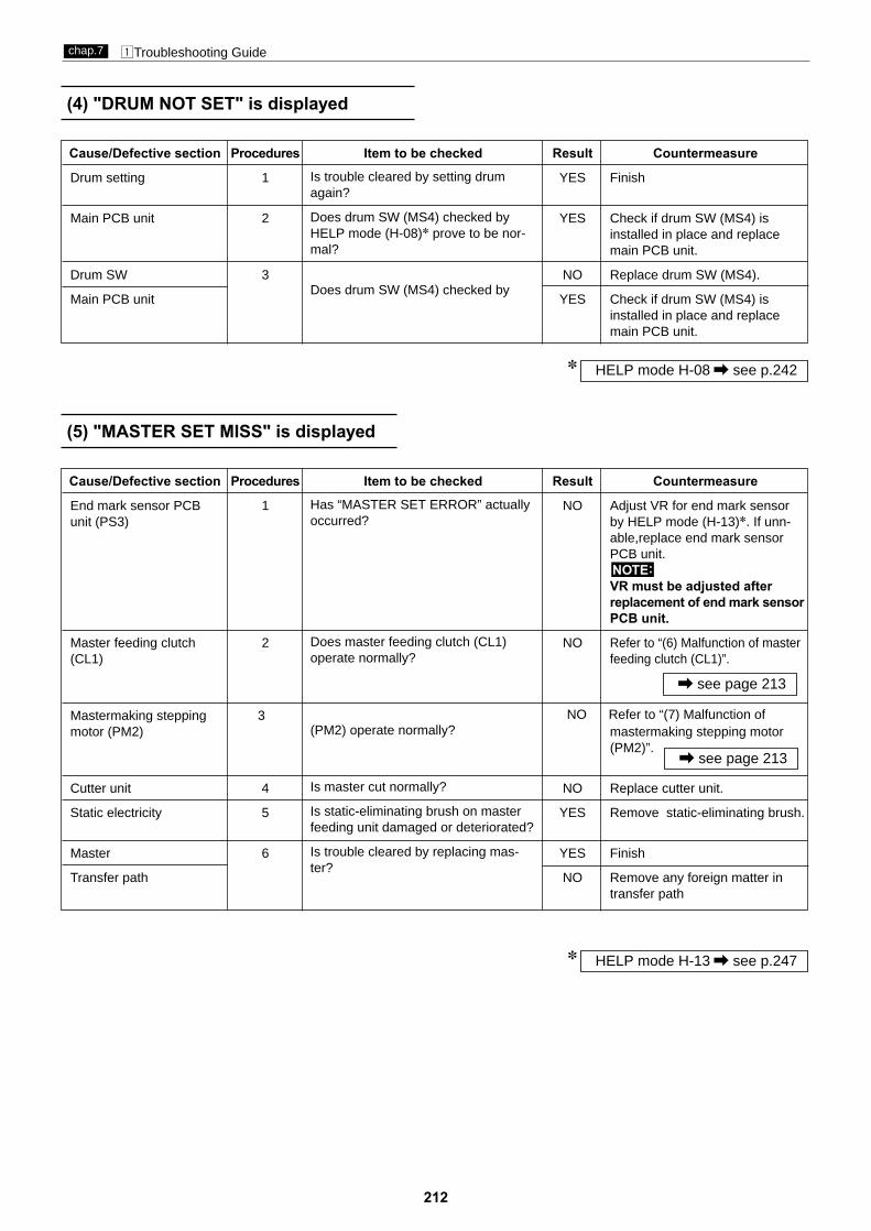
212
zTroubleshooting Guidechap.7
(4) "DRUM NOT SET" is displayed
Cause/Defective section Procedures Item to be checked Result Countermeasure
Drum setting 1 YES Finish
Main PCB unit 2 YES Check if drum SW (MS4) is installed in place and replace main PCB unit.
Drum SW 3 NO Replace drum SW (MS4).
Main PCB unit YES Check if drum SW (MS4) is installed in place and replace main PCB unit.
Is trouble cleared by setting drumagain?
Does drum SW (MS4) checked byHELP mode (H-08)* prove to be nor-mal?
Does drum SW (MS4) checked by
HELP mode H-08 \ see p.242*
(5) "MASTER SET MISS" is displayed
Cause/Defective section Procedures Item to be checked Result Countermeasure
End mark sensor PCB 1 NO Adjust VR for end mark sensor unit (PS3) by HELP mode (H-13)*. If unn-
able,replace end mark sensor PCB unit.
VR must be adjusted afterreplacement of end mark sensorPCB unit.
Master feeding clutch 2 NO Refer to “(6) Malfunction of master(CL1) feeding clutch (CL1)”.
Mastermaking stepping 3motor (PM2) mastermaking stepping motor
(PM2)”.
Cutter unit 4 NO Replace cutter unit.
Static electricity 5 YES Remove static-eliminating brush.
Master 6 YES Finish
Transfer path NO Remove any foreign matter intransfer path
NOTE:
Has “MASTER SET ERROR” actuallyoccurred?
Does master feeding clutch (CL1)operate normally?
(PM2) operate normally?
Is master cut normally?
Is static-eliminating brush on masterfeeding unit damaged or deteriorated?
Is trouble cleared by replacing mas-ter?
\ see page 213
\ see page 213
NO Refer to “(7) Malfunction of
HELP mode H-13 \ see p.247*

213
zTroubleshooting Guidechap.7
(6) Malfunction of master feeding clutch
(7) Malfunction of mastermaking stepping motor
Cause/Defective section Procedures Item to be checked Result Countermeasure
Regulated power supply 1 NO Replace regulated power supply.
Master feeding clutch 2 YES Check wiring and replace master (CL1) feeding clutch.
Main PCB unit 3 YES Finish
Does voltage between regulatedpower supply CN51-1(+) and CN53-1(GND) show 24V?
Does voltage between main PCB unitJ2-11 (+) and -12 (GND) show 24Vwhen master feeding clutch is turnedon?
Is trouble cleared by replacing MainPCB unit?
Cause/Defective section Procedures Item to be checked Result Countermeasure
Load on drive system 1 YES Finish
Regulated power supply 2 NO Replace regulated power supply.
Main PCB unit 3 YES Finish
Is trouble cleared by adjusting tensionof the master feeding unit timing beltor supplying oil to bearing?
Does voltage between regulated
show 24V?
PCB unit?
power supply CN51-1(+) and CN53-1
Is trouble cleared by replacing Main

214
zTroubleshooting Guidechap.7
(8) "MAST. EJECT MISS" is displayed
Cause/Defective section Procedures Item to be checked Result Countermeasure
1 YES Proceed to procedure 5.
Foreign material or dirt on 2 YES Remove any foreign matter and sensors clean.
Master ejection sensor 3 YES Finishphoto-receiving (PS13)
Master ejection sensor 4 YES Finishphoto-emitting PCB
Main PCB unit NO Check bundled wire and connectors and replace main PCB unit.
Roll-up motor (M4) 5 NO Refer to “(9) Malfunction of roll-up motor (M4)”.
Master clamp dirty 6 YES Clean master clamp section.
Master ejection box 7 YES Replace any damaged stripper finger or springs.
Drum master ejection 8 NO Adjust the drum master ejection stop position stop position.
C mode YES Check and adjust C mode.
Has “MAST. EJECT ERROR” actuallyoccurred?
Are there any foreign matter or dirtbetween the master ejection sensorphoto-receiving (PS13) and the mas-ter ejection sensor photo-emittingPCB?
Is trouble cleared by replacing themaster ejection sensor photo-receiv-ing (PS13)?
Is trouble cleared by replacing themaster ejection sensor photo-emittingPCB?
Does roll-up motor (M4) rotate nor-mally?
Is the master clamp section dirty withink or oil?
Is stripper finger or springs damaged?
Is the drum master ejection stop posi-tion within reference value?
(9) Malfunction of roll-up motor
HELP mode H-18 \ see p.252*
Cause/Defective section Procedures Item to be checked Result Countermeasure
Roll-up motor (M4) 1 YES Replace roll-up motor (M4).
Regulated power supply 2 NO Replace regulated power supply.
Main PCB unit 3 YES Finish
Does voltage between main PCB unitJ2-3 (+) and -4 (GND) show 24Vwhen roll-up motor (M4) is operatedwith HELP18?
Does voltage between regulated
show 24V?
Is trouble cleared by replacing MainPCB unit?
power supply CN51-1(+) and CN53-1

215
zTroubleshooting Guidechap.7
(10) "SET PRINT PAPER" is displayed
Paper sensor (MS7) 2 NO Adjust paper sensor (MS7) posi-position tion
Paper sensor (MS7) 3 NO Replace paper sensor (MS7).
Main PCB unit YES Check bundled wire and connectors and replace main PCB unit.
Is actuator for paper sensor (MS7) ispressed when paper tray is set?
When paper sensor (MS7) is checkedwith volt-ohm-milliammeter, does itCLOSE if actuator is pressed andOPEN if released?
(11) "FRONT COVER OPEN" is displayed
Cause/Defective section Procedures Item to be checked Result Countermeasure
Front cover open is 1 YES FinishIs trouble cleared by closing the
front cover?
Front cover SW (MS5) 2 NO Adjust front cover SW (MS5) position position.
Front cover SW (MS5) 3 NO Replace front cover SW (MS5).
Main PCB unit YES Check bundled wire and connectors and replace main PCB unit.
Is front cover SW (MS5) pressedwhen front cover is set?
When front cover SW (MS5) ischecked with volt-ohm-milliammeter,does it OPEN if switch is pressed(front cover open) and CLOSE ifreleased (front cover close)?
detected
Cause/Defective section Procedures Item to be checked Result Countermeasure
No paper is detected 1 YES FinishIs trouble cleared by adding papers?

216
zTroubleshooting Guidechap.7
(12) "SCANNER OPEN" is displayed
Cause/Defective section Procedures Item to be checked Result Countermeasure
Scanner SW (MS3) Adjust the scanner SW (MS3) position position.
Scanner 2 NO Replace the scannerSW (MS3) SW (MS3)
Main PCB unit YES Check bundled wire and connectors and replace main PCB unit.
Is the scanner SW (MS3) pressed when the scanner is closed?
When the scanner SW (MS3) is checked with volt-ohm-milliammeter, does it CLOSE if switch is pressedand OPEN if released?
(13) "ROLL MASTER END" is displayed
HELP mode H-13 \ see p.247*
1 NO
Cause/Defective section Procedures Item to be checked Result Countermeasure
Adjustment for the 2 YES Finishend mark sensor PCB unit (PS3)
End mark sensor PCB 3 YES Finishunit (PS3)
Main PCB unit NO Check bundled wire and connectors and replace main PCB unit.
Is trouble cleared by adjusting theend mark sensor PCB unit (PS3) byHELP mode (H-13)*?
Is trouble cleared by replacing the endmark sensor PCB unit (PS3)?
End mark is detected 1 YES FinishIs trouble cleared by changing a
new master?

217
zTroubleshooting Guidechap.7
(14) "EXCHANGE INK" is displayed
Cause/Defective section Procedures Item to be checked Result Countermeasure
Ink 1 NO Replace ink pack.
Setting method of ink 2 NO Set ink pack properly and teach pack user how to set one.
Main PCB unit 3 YES Check bundled wire and connectors and replace main PCB unit.
Ink detection PCB unit 4 YES Replace Ink detection PCB unit
5 NO Proceed to procedure 7.
Foreign material in ink 6 YES Finishpump
Ink pump NO Replace ink pump.
Regulated power supply 7 NO Replace regulated power supply.
Ink motor (M2) 8 YES Replace ink motor (M2).
Main PCB unit 9 YES Finish
Is enough ink left in ink pack?
Is ink pack set properly?
Is LED on the ink detection PCB unitlit?
Is enough ink left in drum? (Has inkreached detection needle for the inkdetection PCB unit?)
Does ink pump operate?
Is trouble cleared by cleaning inside ofink pump?
Does voltage between regulated
show 24V?
Does voltage between main PCB unitJ2-5 and -6 show 24V?
Is trouble cleared by replacing mainPCB unit?
power supply CN51-1(+) and CN53-1
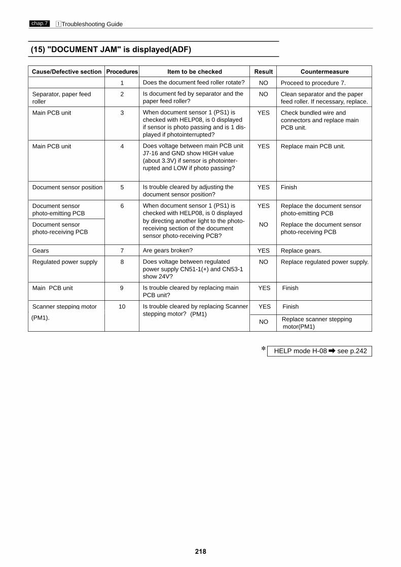
218
zTroubleshooting Guidechap.7
(15) "DOCUMENT JAM" is displayed(ADF)
HELP mode H-08 \ see p.242*
Cause/Defective section Procedures Item to be checked Result Countermeasure
1 NO Proceed to procedure 7.
Separator, paper feed 2 NO Clean separator and the paper roller feed roller. If necessary, replace.
Main PCB unit 3 YES Check bundled wire and connectors and replace main PCB unit.
Main PCB unit 4 YES Replace main PCB unit.
Document sensor position 5 YES Finish
Document sensor 6 YES Replace the document sensor photo-emitting PCB photo-emitting PCB
Document sensor NO Replace the document sensor photo-receiving PCB photo-receiving PCB
Gears 7 YES Replace gears.
Regulated power supply 8 NO Replace regulated power supply.
Main PCB unit 9 YES Finish
Scanner stepping motor 10 YES Finish
(PM1).(PM1)
Does the document feed roller rotate?
Is document fed by separator and thepaper feed roller?
When document sensor 1 (PS1) ischecked with HELP08, is 0 displayedif sensor is photo passing and is 1 dis-played if photointerrupted?
Does voltage between main PCB unitJ7-16 and GND show HIGH value(about 3.3V) if sensor is photointer-rupted and LOW if photo passing?
Is trouble cleared by adjusting thedocument sensor position?
When document sensor 1 (PS1) ischecked with HELP08, is 0 displayed by directing another light to the photo-receiving section of the documentsensor photo-receiving PCB?
Are gears broken?
Does voltage between regulated
show 24V?
Is trouble cleared by replacing mainPCB unit?
Is trouble cleared by replacing Scanner stepping motor?
power supply CN51-1(+) and CN53-1
Replace scanner stepping motor(PM1)
NO

219
zTroubleshooting Guidechap.7
(16) "PAPER RIGHT JAM" is displayed
HELP mode H-06 \ see p.240*
HELP mode H-08 \ see p.242*
Cause/Defective section Procedures Item to be checked Result Countermeasure
Paper 1 NO Use paper conforming to specification.
2 YES Proceed to procedure 7.
Paper jammed 3 YES Refer to “Paper JAM in paper eject side”.
Master ejection box is 4 YES Finishnot closed.
Dirt or foreign material 5 YES Clean the photo-emitting and on sensor photo-receiving sections of JAM
sensor.
Sensor position 6 YES Finish
Document sensor 7 YES Replace JAM sensor photo-photo-emitting PCB emitting PCB.
Document sensor NO Replace JAM sensor photo-photo-receiving PCB receiving PCB.
Stop/JAM detection 8 NO Adjust position of the stop/JAM position sensor (PS6) detection position sensor. If
necessary, replace.
Main PCB unit YES Replace main PCB unit.
Is printing paper long within specifiedvalue?
When JAM sensor 1 (PS12) ischecked with HELP08, is 0 displayedif sensor is photopassing and is 1 dis-played if photointerrupted?
Is paper really jammed at master ejec-tion section?
Is trouble cleared by properly closingthe master ejection box?
Is there any dirt or foreign material onthe JAM sensor photo-emitting orphoto-receiving section?
Is trouble cleared by adjusting theJAM detection sensor position?
Is 0 displayed by directing anotherlight to the photo-receiving section ofthe document sensor photo-receivingPCB when JAM sensor 1 (PS12) ischecked with HELP06?
When drum is checked with HELP06while rotating slowly, does thestop/JAM detection position sensor(PS6) display 0 or 1 according to edgeof photointerrupter?

220
zTroubleshooting Guidechap.7
(17) "PAPER LEFT JAM" is displayed
HELP mode H-06 \ see p.240*
Cause/Defective section Procedures Item to be checked Result Countermeasure
1 YES Finish
Main PCB unit 2 YES Replace the main PCB unit.
P roller sensor (PS9) 3 YES Finishposition
P roller sensor (PS9) 4 YES Finish
Main PCB unit NO Check the bundled wire and connectors and replace the main PCB unit.
Is trouble cleared by checking, refer-ring to “Paper jams in the paper feedside”?
When P roller sensor (PS9) ischecked with HELP06, is 0 displayedif press is turned ON and 1 displayedif OFF?
If no problem is detected by thecheck with HELP06, result on print-ing may differ depending on speedor load. Recommended is to followprocedure 3 and 4 below for furthercheck.
Is the trouble cleared by adjusting Proller sensor (PS9) position?
Is the trouble cleared by replacing Proller sensor (PS9)?
NOTE:
(18) "EXCHG. EJECT-CORE" is displayed
Cause/Defective section Procedures Item to be checked Result Countermeasure
Core 1 YES Insert new core.
Core full SW (MS8) 2 YES Adjust actuator of core full SW actuator (MS8).
Core full SW (MS8) 3 NO Replace core full SW (MS8).
Main PCB unit YES Check bundled wire and connectors and replace main PCB unit.
Core is not included or core is full?
Is core full SW (MS8) pressed whenempty core is installed?
Does core full SW (MS8) tested volt-ohm-milliammeter prove to be nor-mal?
LCD panel

221
zTroubleshooting Guidechap.7
Causes Symptoms Countermeasure
Printing paper not suit-able
• If paper is too thick, it won’t be likely fed. If too thin, dou-ble sheets may be fed.
• Paper not clearly cut: 2 sheets still adhere to eachother.
• Much paper scraps may deteriorate the paper feedroller and separator performance.
Explain causes to user. Have userchange to the paper conforming tospecifications.
Dirt*foreign matter intransfer path
• Paper gets stuck in transfer path, causing creasing andtearing.
Remove any dirt or foreign matter.
Incorrect paper feed pathpressure
• If pressure on paper is insufficient, paper will not be fed.• If pressure on paper is excessive, double sheets will be
fed.
Explain to users how to select cor-rect pressure for paper.
Worn paper feed roller • Paper may not be fed. Replace paper feed roller.
Paper separator unit gap • If gap is too large, separator unit will rattle in direction ofpaper transfer path, causing double sheets to be fed.
• If gap is too small, paper separator unit cannot followangle change due to paper feed shaft up-down move-ment, which may cause double-sheet or slanted feed,and creasing.
Perform paper separator unit gapadjustment.
Paper separator unit • Wear, or adhesion of paper scraps causes deteriorationin separating performance, resulting in double-sheetfeed.
Clean separating surfaces. If anytrouble exists, replace. Perform sep-arator unit gap adjustment on newunit.
Separation pressure • If pressure is very low, no paper will be fed. Perform separation pressure adjust-ment.
Paper tray upper positionlimit
• Paper slant is large, causing creases.• During printing, paper feed errors often occur immedi-
ately before or after paper tray rises.
Perform paper feed tray upper limitsensor adjustment.
Paper feed amount • If amount is too short, paper slant cannot be corrected,printing position may not be uniform, or paper may notbe fed.
• If amount is too long, loop becomes too large, causingpaper to buckle up between paper feed roller and timingroller, resulting in feed error.
Perform paper feed amount adjust-ment.
Paper feed clutch • Clutch slippage will reduce paper feed amount.• If clutch does not disengage properly, the paper feed
segment gear will not return correctly, leading toreduced feed amount.
(See “Paper feed amount” above.)
Replace paper feed cluch.
Guide roller pressure &timing
• If Guide roller pressure is insufficient, paper will not begripped properly, and timing roller will not assure con-stant feed amount. As a result, printing position will notbe uniform. In the worst case, no paper will reach drum.
• If there is a gap between Guide roller and the timingroller, paper slant cannot be corrected.
Perform escape amount adjustmentand escape timing adjustment.
Timing roller • If the timing roller clutch slips, feed amount will not beconstant. As a result, printing position will not be uni-form. In the worst case, no paper will reach drum.
• If the timing roller clutch does not disengage properly,the paper feed segment gear will not return correctly,leading to reduced and unstable feed amount. As aresult, printing position will not be uniform. In the worstcase, no paper will reach drum.
Clean timing roller clutch . Replaceif necessary.
Incorrect signal leveroperation
• Paper may be damaged in the part of leading edge thattouches the signal lever. In the worst case, paper maystick to the signal lever.
Clean bearing unit. Check that sig-nal lever moves smoothly.
(19) Paper Jams in the Paper Feed Side
\ see page 169
\ see page 169
\ see page 170
\ see page 170
HELP mode H-67 / 284 page
\ see page 172

222
zTroubleshooting Guidechap.7
Causes Symptoms Countermeasure
Printing paper not suit-able
• If paper is too thin, it will stick to drum and scrunch up.• If grain of paper is sideways relative to transfer direction, paper will
crunch up, or get jammed on the paper receiving plate.• If paper curl upward, it will likely scrunch up. If curl downward, it will
likely get jammed on the paper receiving plate.
Explain causes to users. Have userchange to paper conforming tospecifications.
Image of document • If set-solid exists near leading edge of paper, paper will likely scrunchup.
• If set-solid is blasted to one side of paper, paper will not be ejected ina straight line. As a result, ejected paper will be disorderly piled andlikely jam on the paper receiving plate.
• Adjust leading edge margin toabout 10 mm. (Too long marginwill cause adverse results.)
• Explain causes to users. If possi-ble, have user change position forset-solid.
Static electricity • If ambient air is dry, static electricity may cause disordered piles orscrunch-up of paper.
• Explain causes to users. Have user desistfrom excessive use of A/C or heating.
• If possible, have user take anti-drynessmeasures including humidifiers.
Leading edge margin • If leading edge margin is not correct, scrunch-up of paper will likelyresult.
Scrunch-up of paper may also result if the margin is too long.IMPORTANT:
• Perform printing position sensorsadjustment.
Guide roller pressure &timing
• If Guide roller pressure is insufficient, paper will not be gripped proper-ly, causing less feed amount determined by timing roller, or disap-pearance of leading edge margin. This results in the paper scrunch-up.
Perform escape amount and escapetiming adjustments.
Timing roller clutch • Any slippage of the timing roller clutch will reduce feed amount andeliminate leading edge margin. This results in the paper scrunch-up.
• If the timing roller clutch does not disengage properly, the timing rollersegment gear will not return correctly, causing reduction of feedamount or disappearance of leading edge margin. As a result, paperwill scrunch up.
Clean timing roller clutch. Repair ifnecessary.
Paper stripper finger • If timing is too low, or the gap between drum and the leading edge ofpaper is too large, paper stripper finger will not enter into the gap,causing the paper scrunch-up.
Perform paper stripper finger adjust-ment.
Air • If sufficient air is not delivered from the tip of the paper stripper finger,it will not lift the leading edge of paper off drum. Scrunch-up of paperwill result.
• Check if the hole in the fingers tipis blocked by foreign matter.
• Check pipes for kinks or discon-nections.
• Check valves and O-rings on theair pump.
Paper ejection belt • If the speed of the paper ejection belt, if cannot eject the paper ontothe paper receiving plate with sufficient force.As a result, there will be paper jams in the vicinity of the dischargeport. (Sometimes the trailing edge of the paper gets caught in the jam-ming sensor and a paper jamming error is displayed.)
If the belt is broken or stretched,replace it.
Paper ejection fan unit • If the suction force of the fan drops, it will not be able to blow thepaper (which has risen clear of the ejection belt) onto the paperreceiving plate with be paper jams in the vicinity of the discharge port.(Sometimes the trailing edge of the paper gets caught in the jammingsensor and a paper jamming error is displayed.)
Clean the fan. If it still does not workproperly, replace it.
Ink • Too much ink transferred to paper will likely cause scrunch-up ofpaper.
• Perform ink volume adjustment of drum.• Explain user that ink transfer volume
increases immediately after paper scrunch-up, and advise user to restart printing atstandard speed, then.
\ see page 179
\ see page 178
\ see page 172
\ see page 173
(20) Paper Jams in Paper Eject Side

223
zTroubleshooting Guidechap.7
This machine has a self-diagnosis function. Thestate of the machine is always checked with thisfunction and is displayed with code on the controlpanel. The following are the code display, cause anddetection timing.
xError Display
Code display
LCD panel
E 1 1 1
Code display Cause Detection timing
E001
• The main motor (M1) is defective.• The main PCB Unit is defective.• The encoder sensor (PS7) is defective.
• While the drum rotation signal is lit, the encoder sen-sor (PS7) cannot detect the edge for 1 second.
E002
• The elevator motor (M2) is defective.• The elevator top limit sensor (PS9) is defective.• The elevator bottom limit switch (MS6) is defective.- The main PCB Unit is defective.• The elevator operation is defective.
• The elevator does not reach the top limit for 30 sec-onds after the elevator motor (M2) up signal is lit.
• The elevator does not reach the bottom limit for 30seconds after the elevator motor (M2) down signalis lit.
E009 • The thermal head substrate is defective.• The thermal head is defective.
• At start of mastermaking, thermal head drive voltagedoes not reach regulation value.
E003
• The cutter motor is defective.• The cutter limit switch is defective.- The main PCB Unit is defective.
• The cutter does not reach the limit for 30 sec-onds after the cutter motor move signal is lit.
E004
E040
- The main PCB Unit is defective.
• The master set sensor is defective.• The cord for master set sensor is unconnected.
• The master set sensor signal is detected continuallyfor 20 seconds after power is on.
• The lamp is defective.• The invertor unit is defective.• The CCD is defective.• Main PCB unit is defective.
• In the lamp lighting check, amount of light receivedby CCD does not reach regulation value. (Performthe lamp lighting check once only, with the powerturned on.)
• The main PCB Unit is defective.

224
MEMO

225
Chapter 8 HELP Mode
z HELP Mode List ........................................................
x Overview ....................................................................
c HELP Mode Functions andOperation Procedures ..............................231
(1) Basic Procedure for Accessing HELP Modes .....231(2) Guide to the HELP Mode Descriptions ..............231
¡HELP Mode Descriptions ....................................233
7
(3) Guide to version up ..............................................232
226
230

226
z Help mode Listchap.8
z HELP Mode ListHELP
Mode No. Description Classification Page
H-00 Display of ROM versions ROM version displays 233
H-01 Display and adjustment of print speeds Adjustment /specificationsetting
234
H-02 Elevator motor Function testing 236
H-03 Tape Cluster Function testing 237
H-04 Ink replenishment Function testing Function testing
H-05
Checking of condition of master ejection sensor and other sensorslisted below¡Paper feed sensor,¡
Top/Bottom limit sensor, Top/Bottom center sensor
¡Cutter switch of operation /non-operation side,Drum rotation switchMaster lever feed sensor,Paper sensor,Drum cover switch
Sensor/switch conditiondisplay 239
H-06
Checking of condition of sensors listed below¡
Drum master attachment /detachment position sensor ,
Press roll sensor, Drum stop/paper ejection jam Light reception by the paper ejection jam sensor
¡
Elevator upper limit sensor, Elevator lower limit sensor,Feed tray
B mode sensor, A/C mode sensorSensor/switch conditiondisplay 240
H-07
Checking of condition of switches listed below:
Sensor/switch conditiondisplay 241
H-08
Checking of condition of sensors/swtches listed below:¡Document sensor1, Document sensor2¡Upper cover switch, Master roll Full switch, Drum switch
Sensor/switch conditiondisplay 242
H-09 Checking of master attachment position, jam sensing position,master detachment position and drum stop position Function testing 243
H-10 (1) Function testing of LAMP Function testing (1)244
247
(2)244
H-11(1) Document darkness values and scanner test (for use in factory checks) Sensor/switch condition
display245
H-12
H-13 Sensor/switch conditiondisplay
Value of thermistor for Main PCB and Thermal head¡Value of encoder count of drum rotated
¡
Paper ejection jam sensor
¡¡
descend switch,Tape switch
Value of ADF received¡
(2) Testing of functioning of ADF scan motor operation function
(2) Testing of ADF.
: ADF
ADF:242
(1) Checking of shading memory Function testing 246
ADF:245
Function testing
Function testing
(1) Check the condition of the end mark sensors
238
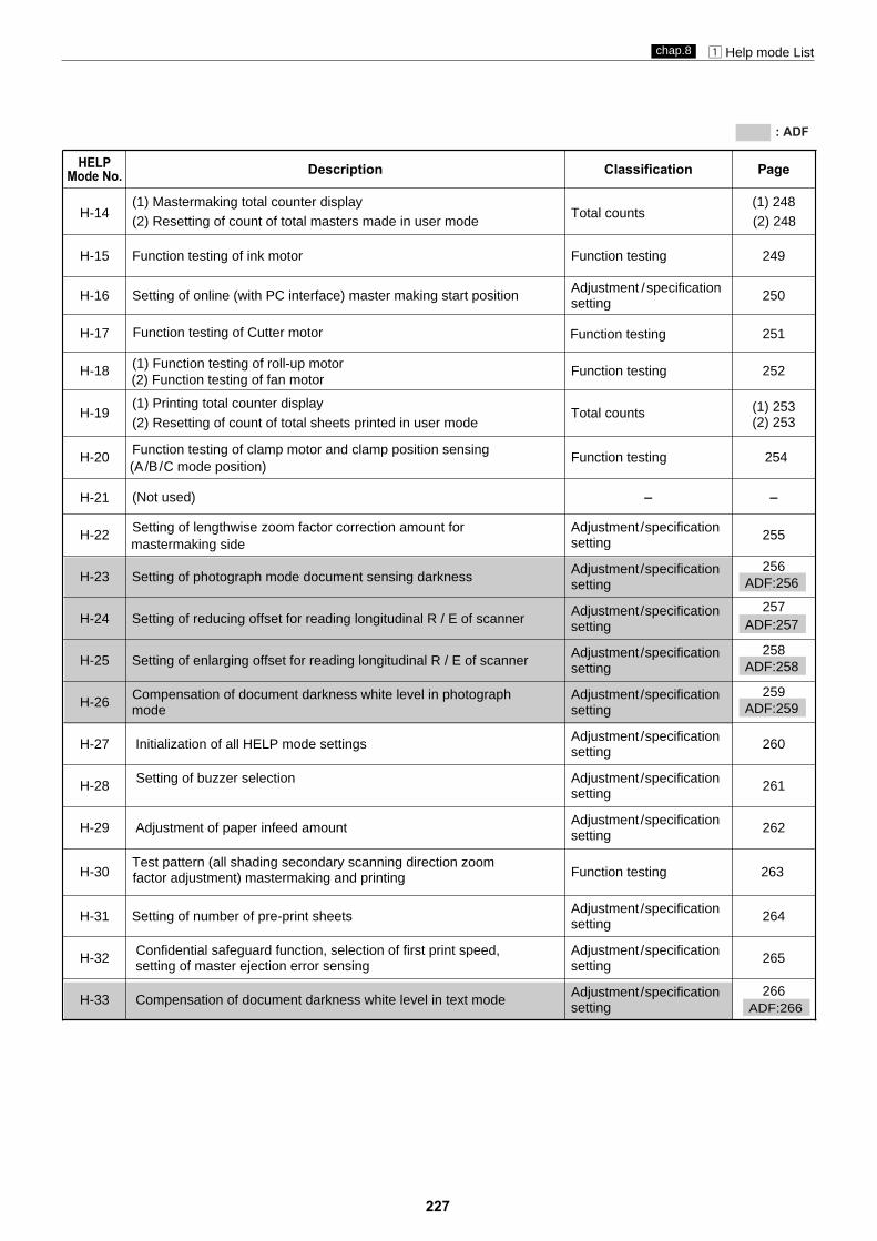
227
z Help mode Listchap.8
HELPMode No. Description Classification Page
H-14(1) Mastermaking total counter display(2) Resetting of count of total masters made in user mode
Total counts(1) 248(2) 248
H-20 Function testing of clamp motor and clamp position sensing (A/B/C mode position)
Function testing 254
H-23 Setting of photograph mode document sensing darkness Adjustment /specificationsetting
256
H-24 Setting of reducing offset for reading longitudinal R / E of scanner Adjustment /specificationsetting
257
H-25 Setting of enlarging offset for reading longitudinal R / E of scanner Adjustment /specificationsetting
258
H-26 Compensation of document darkness white level in photograph mode
Adjustment /specificationsetting
259
H-27 Initialization of all HELP mode settings Adjustment /specificationsetting 260
H-28 Setting of buzzer selection Adjustment /specificationsetting 261
H-29 Adjustment of paper infeed amount Adjustment /specificationsetting
262
H-30Test pattern (all shading secondary scanning direction zoomfactor adjustment) mastermaking and printing Function testing 263
H-31 Setting of number of pre-print sheets Adjustment /specificationsetting 264
H-32 Confidential safeguard function, selection of first print speed, setting of master ejection error sensing
Adjustment /specificationsetting 265
H-33 Compensation of document darkness white level in text mode Adjustment /specificationsetting
266
4 4H-21 (Not used)
H-22 Setting of lengthwise zoom factor correction amount formastermaking side
Adjustment /specificationsetting 255
H-19(1) Printing total counter display(2) Resetting of count of total sheets printed in user mode
Total counts (1) 253(2) 253
H-18 (1) Function testing of roll-up motor Function testing 252
H-17
H-16 Setting of online (with PC interface) master making start positionAdjustment /specificationsetting 250
H-15 Function testing of ink motor Function testing 249
Function testing of Cutter motor Function testing
(2) Function testing of fan motor
ADF:256
ADF:257
ADF:258
ADF:259
: ADF
ADF:266
251

228
z Help mode Listchap.8
HELPMode No. Description Classification Page
H-40
H-41Automatic initialization of the control panel setting, setting of repeat count display,energy save mode and auto power off
Adjustment/specificationsetting
272
H-45-49 (Not used)
H-50 Setting of text mode document sensing darkness Adjustment/specificationsetting
276
H-51/52
H-53 Adjustment of widthwise (operation side) mastermaking start position for online mastermaking
Adjustment/specificationsetting
277
H-42 Setting of paper selection specification Adjustment/specificationsetting
273
275
H-43
Adjustment/specificationsetting
H-44 Setting of thermal head resistance ranking
H-37 Adjustment of mastermaking start position when scanner is used Adjustment/specificationsetting
269
H-39
4
4
4 4
H-38
H-34 (Not used) 4 4
H-35 Adjustment of scanner leading edge sensing position Adjustment/specificationsetting
267
H-36 Adjustment of scanner widthwise (operation side) sensing position Adjustment/specificationsetting
268
Function testing of clutches test and auto power off
(Not used)
Adjustment of drum speed automatically
(Not used)
H-56 Seeting for selecting manipulation language
H-57/58
H-54
H-55 Setting of ink check at printing start, cutting operation modefor master cutting, and interlocks
Adjustment/specificationSetting
Adjustment/specificationSetting
278
279
ADF:267
ADF:268
ADF:269
ADF:276
: ADF
271
270Adjustment/specificationsetting
4
Function testing
Setting of thermal head offset valueAdjustment/specificationsetting
274
(Not used)
4 4
4 4
(Not used) 4 4
H-59 Setting of endmark sensor2 Setting 280Adjustment/specification
H-60 (Not used)
(Not used)
H-61 Function test for LCD screen and LED indicators 281
H-62
4 4
4 4
Function testing(for use in factory checks)
Setting
H-63
H-64 Buzzer (tone) setting Setting 283Adjustment/specification
Setting for A4 master cutAdjustment/specificationSetting
282

229
z Help mode Listchap.8
HELPMode No. Description Classification Page
H-66Setting: clamp opening/closing timing of when a master is attached;H-67/68 ON/OFF
Adjustment/specificationSetting
284
H-72 Adjustment/specificationSetting
288
H-70/71
H-73 Adjustment/specificationSetting
289
H-68 Setting of paper feed angle
H-69 Setting of model Adjustment/specificationSetting
287
H-67 Setting of paper feed length Adjustment/specificationSetting
Adjustment/specificationSetting
285
286
H-65 (Not used) 4 4
(Not used)
Adjustment of master making area length
Adjustment of master making area length on online printing
4 4
H-76
H-80
H-86
H-94 UID ADMINISTRATOR password reset
Document darkness correction for photograph/text mode Adjustment/specificationSetting
291
Setting of speed rank, ADF and ink save modeAdjustment/specificationSetting 292
Setting of manual batch printingAdjustment/specificationSetting
294
Adjustment/specification
Setting304
H-83 (1) Display of ROM version for ADF Adjustment/specificationSetting
293
H-84 (1) Checking of communication for ADF Adjustment/specificationSetting
296
H-74
H-77/79 (Not used) 4 4
H-87-88 (Not used) 4 4
H-93Adjustment of widthwise (operation side) scaning start position
H-90Adjustment/specificationSetting
300
H-91 Setting of tape lenghth for Tape cluster on online mode Adjustment/specificationSetting
301
H-92 Setting of tape lenghth for Tape cluster
Adjustment/specification
Setting302
H-81/82 (Not used) 4 4
H-85
Adjustment/specificationSetting
290 Setting of thermal head temperature supplementing and master making darkness rank.
H-75 (Not used) 4 4
Adjustment for image sampling timing of scanning Adjustment/specificationSetting
295(for use in factory checks).
H-89 Setting of Tape cluster Adjustment/specificationSetting
297
Setting of several special functions.
305H-97 The display for machine model.Adjustment/specificationSetting
: ADF
Adjustment/specificationSetting
303for 4-up and 8-up
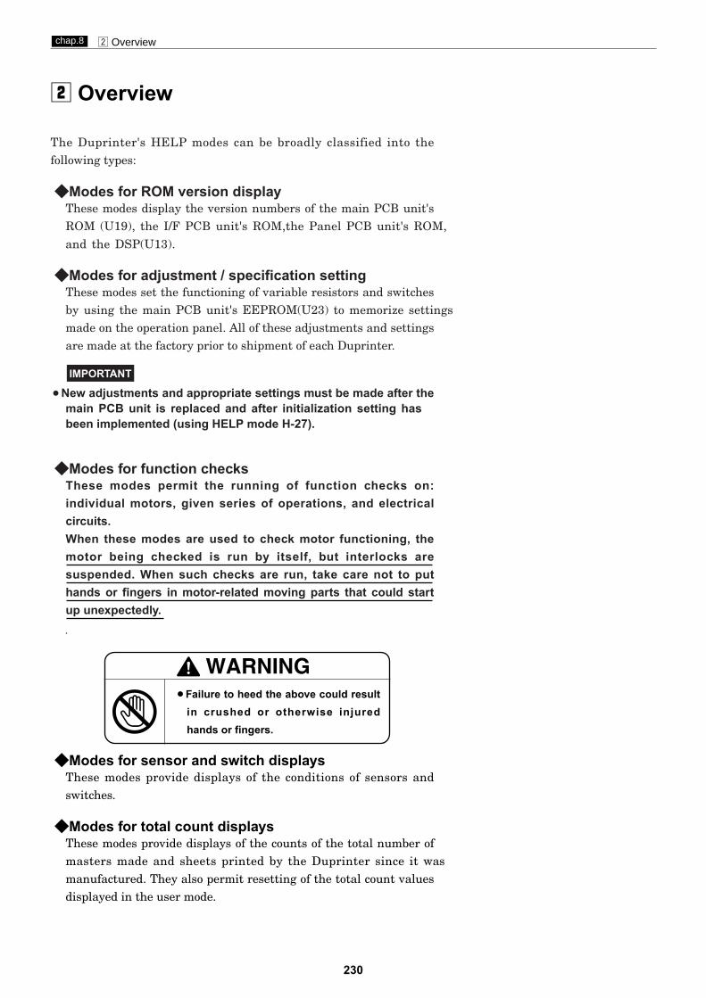
230
x Overviewchap.8
x Overview
¡Failure to heed the above could resultin crushed or otherwise injuredhands or fingers.
The Duprinter's HELP modes can be broadly classified into thefollowing types:
◆ Modes for ROM version displayThese modes display the version numbers of the main PCB unit'sROM (U19), the I/F PCB unit's ROM,the Panel PCB unit's ROM,
◆ Modes for adjustment / specification settingThese modes set the functioning of variable resistors and switchesby using the main PCB unit's EEPROM(U23) to memorize settingsmade on the operation panel. All of these adjustments and settingsare made at the factory prior to shipment of each Duprinter.
¡New adjustments and appropriate settings must be made after themain PCB unit is replaced and after initialization setting hasbeen implemented (using HELP mode H-27).
◆ Modes for function checksThese modes permit the running of function checks on:individual motors, given series of operations, and electricalcircuits.When these modes are used to check motor functioning, themotor being checked is run by itself, but interlocks aresuspended. When such checks are run, take care not to puthands or fingers in motor-related moving parts that could startup unexpectedly.
IMPORTANT
◆ Modes for sensor and switch displaysThese modes provide displays of the conditions of sensors andswitches.
◆ Modes for total count displaysThese modes provide displays of the counts of the total number ofmasters made and sheets printed by the Duprinter since it wasmanufactured. They also permit resetting of the total count valuesdisplayed in the user mode.
and the DSP(U13).

231
c HELP Mode Function and Operation Procedureschap.8
c HELP Mode Functions and Operation Procedures
(1) Basic Procedure for Accessing HELP Modes
(2) Guide to the HELP Mode Descriptions
qDuring use of the Duprinter: first put the machine into the
standby state, then turn the power switch OFF.
wSimultaneously press and hold down the and printing
speed keys, and turn the power switch ON with those keys helddown. After about 2 seconds, a beep-beep-beep tone will sound, andthe HELP mode display will appear.
eUsing the numeric keys, enter the number of the HELP mode you
want to access.Example: To access HELP mode H-00, enter [0], [0].
rPress the PRINT key. The HELP mode specified in ewill be
accessed, and either the initial value (value set at factory), or thecurrently set value, for the mode will be displayed.
From this point on, follow the procedure given below for theparticular mode accessed.
The descriptions of each HELP mode given on the following pagesare laid out as follows:
HELP mode number
Referencesto relatedpages
LC displayfor function
Operationprocedure forindividualfunctions
Main functions
c HELP Mode Function and Operation Procedureschap.7
1. Functions
(1) Tape cluster function test
(1) Testing the tape cluster's functioning
qAccess HELP mode H-03, and press the PRINT key.For the basic procedure for accessing HELP modes.
wPress and hold down the TEST PRINT key. The tape feed motor
will run, and feed out the tape, for as long as the key is held down.
T
2. Operation procedure
H-03 (1)Function testingHELP mode
H - 0 3Mode number flashes
\See page 293
For removal
For desccription of operation
\See page 150
\See page 195
(2) Stacker rise/descent motor function testing
Function category
H E L P S E L E C T 0 0
Mode number
U 6 B 1 . 1 1 0 p : V 1 . 1 1

232
c HELP Mode Function and Operation Procedureschap.8
(3)Guide to version up
IMPORTANT
qRemove screw1 and loosen screw2,make cover to fall down,
w
Simultaneously press and hold down the DOCUMENT MODE key
and CLEAR key , and turn the power switch ON with those keys held down. After about 2 seconds, a beep-beep-beep tone will sound, andthe version up mode display will appear.
e
rOperate according to DDL-01 service manual or DDL-02 service
manual to version up,when finished normally,the LCD panel will be shown as right.
screw1 cover
screw2
version up socket
and make version up socket out.
Make sure the power is turned off,connect the connector of downloader( DDL-01 OR DDL-02 ) to version up socket.
Turn power off,remove the connector of downloader from the socket,then fix the cover back with the screws.
t
connector

233
c HELP Mode Function and Operation Procedureschap.8
1. Functions
Display of ROM versions¡ Displays version of the main PCB unit's ROM.¡ Displays version of the I/F PCB unit.
¡ROM version for I/F PCB unit is displayed only when connected with thecomputer.
Displaying ROM versionsqAccess HELP mode H-00, and press the PRINT key.
For the basic procedure for accessing HELP modes.
wPress the STOP key. The HELP mode selection display will
reappear.a To exit the HELP mode : Turn the power switch OFF.a To access another HELP mode : Enter the desired mode number
using the numeric keys.
2. Operation procedure
H-00 ROM version displaysHELP mode
Main PCB unit
¡ HELP Mode Descriptions
\See page 231
IMPORTANT
¡Displaying ROM version
I/F PCB unit
U 6 B 1 . 1 1 0 p : V 1 . 1 1
¡Displays version of the Panel PCB unit.
¡ Displays version of the DSP.
PANEL PCB unit DSP
K E Y V 1 . 1 1D S P V1 . 1 1
Displays version of the main PCB unit's ROM and I/F PCB unit
as right when TEXT mode is selected.
Displays version of the panel PCB unit's ROM and DSP as right
when TEXT/PHOTOGRAPH mode is selected.
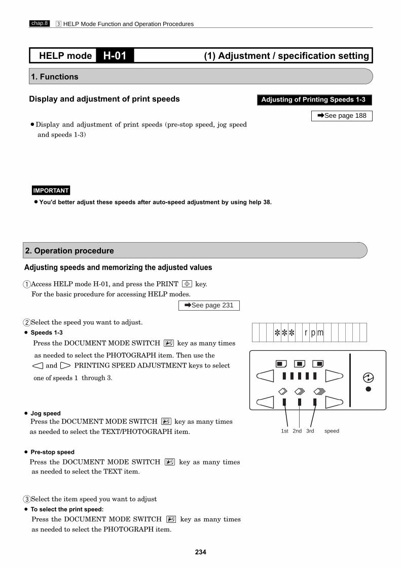
234
c HELP Mode Function and Operation Procedureschap.8
1. Functions
Display and adjustment of print speeds
¡Display and adjustment of print speeds (pre-stop speed, jog speedand speeds 1-3)
H-01 (1) Adjustment / specification settingHELP mode
Adjusting of Printing Speeds 1-3
\See page 188
¡ Jog speedPress the DOCUMENT MODE SWITCH key as many timesas needed to select the TEXT/PHOTOGRAPH item.
¡ Pre-stop speedPress the DOCUMENT MODE SWITCH key as many times
eSelect the item speed you want to adjust¡ To select the print speed:
Press the DOCUMENT MODE SWITCH key as many timesas needed to select the PHOTOGRAPH item.
Adjusting speeds and memorizing the adjusted values
qAccess HELP mode H-01, and press the PRINT key.For the basic procedure for accessing HELP modes.
wSelect the speed you want to adjust.¡ Speeds 1-3
2. Operation procedure
\See page 231
1 1 1 r p mPress the DOCUMENT MODE SWITCH key as many times
as needed to select the PHOTOGRAPH item. Then use theand PRINTING SPEED ADJUSTMENT keys to select
one of speeds 1 through 3.
1st 2nd 3rd speed
as needed to select the TEXT item.
¡You'd better adjust these speeds after auto-speed adjustment by using help 38.
IMPORTANT

235
c HELP Mode Function and Operation Procedureschap.8
H-01 (1) Adjustment / specification settingHELP mode
rUse the and PRINTING POSITION ADJUSTMENT keys to
adjust the speed value.
Speed
Pre-stop
JOG
1st.
2nd.
3rd.
Adjustment standard (rpm)
Print speed
5 - 7
16 - 18
63 - 65
87 - 89
140-142
tTo display or adjust other another speed(s), repeat steps wthrough r.
yPress the STOP key. The newly adjusted value(s) will be
memorized, and the HELP mode selection display will reappear.a To exit the HELP mode: Turn the power switch OFF.a To access another HELP mode: Enter the desired mode number
using the numeric keys.
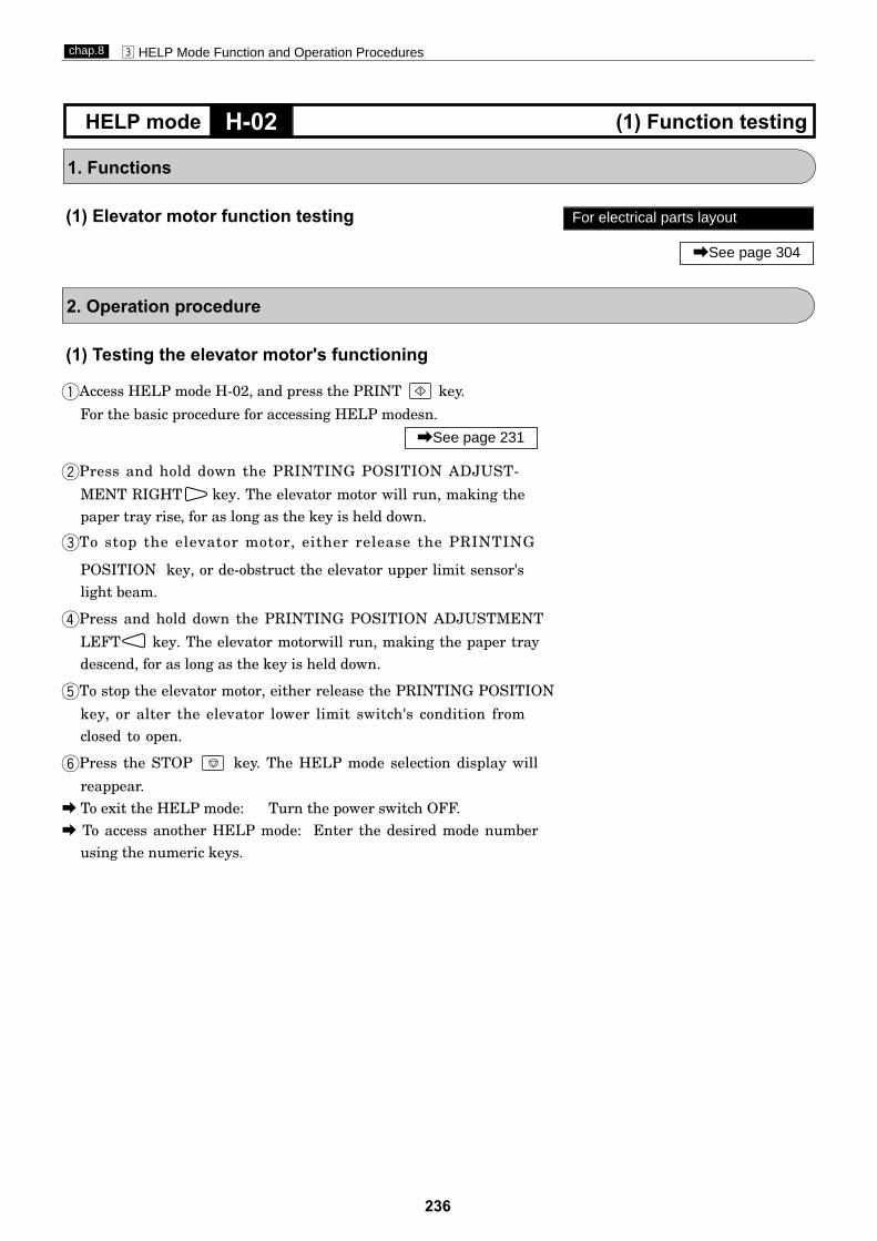
236
c HELP Mode Function and Operation Procedureschap.8
1. Functions
H-02 (1) Function testingHELP mode
2. Operation procedure
For electrical parts layout
\See page 304
(1) Elevator motor function testing
(1) Testing the elevator motor's functioning
qAccess HELP mode H-02, and press the PRINT key.
For the basic procedure for accessing HELP modesn.
wPress and hold down the PRINTING POSITION ADJUST-
MENT RIGHT key. The elevator motor will run, making the paper tray rise, for as long as the key is held down.
eTo stop the elevator motor, either release the PRINTING
POSITION key, or de-obstruct the elevator upper limit sensor'slight beam.
rPress and hold down the PRINTING POSITION ADJUSTMENT
LEFT key. The elevator motorwill run, making the paper tray descend, for as long as the key is held down.
tTo stop the elevator motor, either release the PRINTING POSITION
key, or alter the elevator lower limit switch's condition from closed to open.
yPress the STOP key. The HELP mode selection display will
reappear.a To exit the HELP mode: Turn the power switch OFF.a To access another HELP mode: Enter the desired mode number
using the numeric keys.
\See page 231

237
c HELP Mode Function and Operation Procedureschap.8
1. Functions
(1) Tape cluster function test
(1) Testing the tape cluster's functioning
qAccess HELP mode H-03, and press the PRINT key.For the basic procedure for accessing HELP modes.
wPress and hold down the TEST PRINT key. The tape feed motor
will run, and feed out the tape, for as long as the key is held down.
eRelease the TEST PRINT key. The tape cutting solenoid will
be activated, and the tape will be cut.
T
T
rPress the STOP key. The HELP mode selection display will
reappear.a To exit the HELP mode: Turn the power switch OFF.a To access another HELP mode: Enter the desired mode number
using the numeric keys.
2. Operation procedure
H-03 (1)Function testingHELP mode
\See page 231
: T A P E T E S T
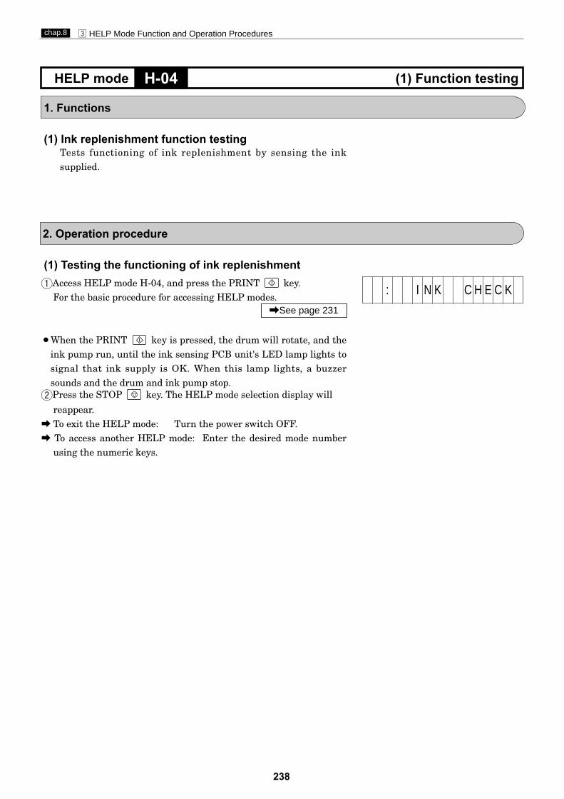
238
c HELP Mode Function and Operation Procedureschap.8
1. Functions
(1) Ink replenishment function testingTests functioning of ink replenishment by sensing the inksupplied.
(1) Testing the functioning of ink replenishmentqAccess HELP mode H-04, and press the PRINT key.
For the basic procedure for accessing HELP modes.
¡When the PRINT key is pressed, the drum will rotate, and theink pump run, until the ink sensing PCB unit's LED lamp lights tosignal that ink supply is OK. When this lamp lights, a buzzersounds and the drum and ink pump stop.
wPress the STOP key. The HELP mode selection display will
reappear.a To exit the HELP mode: Turn the power switch OFF.a To access another HELP mode: Enter the desired mode number
using the numeric keys.
2. Operation procedure
H-04 (1) Function testingHELP mode
\See page 231
: I N K C H E C K

239
c HELP Mode Function and Operation Procedureschap.8
eWhen TEXT/PHOTOGRAPH mode is selected,the value of thermistor
of main PCB and thermal head.
1. Functions
(1) Checking of condition of master ejection sensor andother sensors listed below¡
Displays the value of thermistor for Main PCB and Thermal head.¡
Runs checks on the Paper feed sensor,Top/Bottom limit sensor,Top/
(1) Checking the condition of master ejection sensorand other listed sensorsqAccess HELP mode H-05, and press the PRINT key.
For the basic procedure for accessing HELP modes.
wWhen TEXT mode is selected, A display indicating the conditions of the following sensors and the master ejection sensor's photo-receiving amount will appear, the amount is a value between 000 and
◆ Reading the displayed value of D¡ [000] : Maximum amount of light received¡ [255] : No light received¡ [000 displayed value 180]: No master between sensor
components* Displayed value when master present > Displayed value when
master absent
r
Press the STOP key. The HELP mode selection display will
reappear.a To exit the HELP mode: Turn the power switch OFF.a To access another HELP mode: Enter the desired mode number
using the numeric keys.
2. Operation procedure
H-05 (1) Sensor / switch condition displayHELP mode
Amount of light received bymaster ejection sensor
\See page 231
For electrical parts layout
\See page 301
Master ejection sensor
\See page 75
A : 111 B : 11 1
1 1 1A : 1 B : 1 C : 1 D :
255.
Top/bottom limit sensor 1 = Photointerrupting
Top/bottom center sensor1 = Photointerrupting
Paper feed sensor 0=paper present
thermal headmain PCB
When PHOTOGRAPH mode is selected, the value of encoder count of drum rotated will displayed in hex. 11111111
encorder
t
◆ Paper feed sensor : A◆ Top/bottom limit sensor : B◆ Top/bottom center sensor : C
Bottom center sensor.Displays amount of light received by master ejection sensor.
Display the value of encoder count of drum rotated.¡
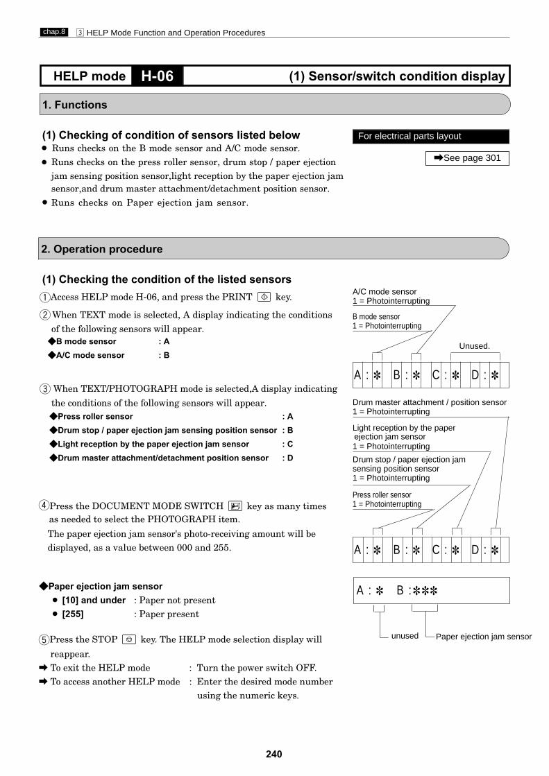
240
c HELP Mode Function and Operation Procedureschap.8
1. Functions
(1) Checking of condition of sensors listed below¡ Runs checks on the B mode sensor and A/C mode sensor.
Runs checks on the press roller sensor, drum stop / paper ejection jam sensing position sensor,light reception by the paper ejection jam
¡
Runs checks on Paper ejection jam sensor.
(1) Checking the condition of the listed sensorsqAccess HELP mode H-06, and press the PRINT key.
wof the following sensors will appear.
◆ Press roller sensor : A◆ Drum stop / paper ejection jam sensing position sensor : B◆ Light reception by the paper ejection jam sensor : C◆ Drum master attachment/detachment position sensor : D
ethe conditions of the following sensors will appear.
◆ B mode sensor : A◆ A/C mode sensor : B
rPress the DOCUMENT MODE SWITCH key as many times
The paper ejection jam sensor's photo-receiving amount will bedisplayed, as a value between 000 and 255.
◆ Paper ejection jam sensor¡ [10] and under : Paper not present¡ [255] : Paper present
tPress the STOP key. The HELP mode selection display will
reappear.a To exit the HELP mode : Turn the power switch OFF.a To access another HELP mode : Enter the desired mode number
using the numeric keys.
2. Operation procedure
H-06 (1) Sensor/switch condition displayHELP mode
Drum master attachment / position sensor1 = Photointerrupting
Light reception by the paperejection jam sensor 1 = Photointerrupting
Drum stop / paper ejection jamsensing position sensor1 = Photointerrupting
Press roller sensor1 = Photointerrupting
A/C mode sensor 1 = Photointerrupting
B mode sensor1 = Photointerrupting
For electrical parts layout
\See page 301
A : 1 B : 1 C : 1 D : 1
A : 1 B : 1 C : 1 D : 1
When TEXT mode is selected, A display indicating the conditions
Unused.
A : 1 B : 11 1
Paper ejection jam sensorunused
When TEXT/PHOTOGRAPH mode is selected,A display indicating
sensor,and drum master attachment/detachment position sensor.¡
as needed to select the PHOTOGRAPH item.
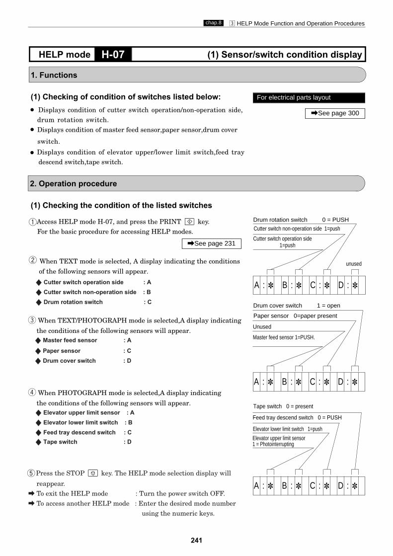
241
c HELP Mode Function and Operation Procedureschap.8
1. Functions
(1) Checking of condition of switches listed below:¡ Displays condition of cutter switch operation/non-operation side,
drum rotation switch.Displays condition of master feed sensor,paper sensor,drum cover¡
Displays condition of elevator upper/lower limit switch,feed traydescend switch,tape switch.
(1) Checking the condition of the listed switches
qAccess HELP mode H-07, and press the PRINT key.For the basic procedure for accessing HELP modes.
w
SS Cutter switch operation side : A
SS Cutter switch non-operation side : B
SS Drum rotation switch : C
e
SS Master feed sensor : A
SS Paper sensor : C
SS Drum cover switch : D
r
Press the STOP key. The HELP mode selection display will
reappear.a To exit the HELP mode : Turn the power switch OFF.a To access another HELP mode : Enter the desired mode number
using the numeric keys.
2. Operation procedure
H-07 (1) Sensor/switch condition displayHELP mode
Elevator lower limit switch 1=push
Unused
Master feed sensor 1=PUSH.
\See page 231
For electrical parts layout
\See page 300
A : 1 B : 1 C : 1 D : 1
A : 1 B : 1 C : 1 D : 1
Drum rotation switch 0 = PUSH
Feed tray descend switch 0 = PUSH
Cutter switch operation side 1=push
A : 1 B : 1 C : 1 D : 1
Cutter switch non-operation side 1=push
unusedof the following sensors will appear.
When TEXT mode is selected, A display indicating the conditions
the conditions of the following sensors will appear.
When TEXT/PHOTOGRAPH mode is selected,A display indicating
the conditions of the following sensors will appear.
When PHOTOGRAPH mode is selected,A display indicating
t
Paper sensor 0=paper present
Drum cover switch 1 = open
Elevator upper limit sensor
Tape switch 0 = presentSS Elevator upper limit sensor : A
SS Elevator lower limit switch : B
SS Feed tray descend switch : CSS Tape switch : D
¡
switch.
1 = Photointerrupting

242
c HELP Mode Function and Operation Procedureschap.8
(1) Checking the condition of the listed sensorsqAccess HELP mode H-08, and press the PRINT key.
For the basic procedure for accessing HELP modes.
w
e
SS
SS
1. Functions
(1) Checking of condition of switches listed below:¡ Displays condition of upper cover sensor,master roll FULL
switch, drum presence switch.
tPress the STOP key. The HELP mode selection display will
reappear.a To exit the HELP mode : Turn the power switch OFF.a To access another HELP mode : Enter the desired mode number
using the numeric keys.
2. Operation procedure
H-08 (1) Sensor/switch condition displayHELP mode
\See page 231
For electrical parts layout
\See page 300, 301
r
SS ADF cover switch : C
Drum switch : D
A : 1 B : 1 C : 1
A : 1 B : 11 1
ADF home position sensorFixed document homeADF home position sensor : AFixed document home position sensor : B
the conditions of the following sensors will appear.
When TEXT mode is selected, the display indicating
indicating the conditions of the following sensors will
When TEXT/PHOTOGRAPH mode is selected,the display
S
S
Paper roll FULL switch : B
D : 1
A : 1 B : 11 1
ADF document sensor
ADF document position sensor
¡ Displays the value of ADF received .
1 C : 1 D :
ADF cover switch
ADF jam sensor
SS ADF document sensor : A
SS
SS ADF document position sensor :D
ADF jam sensor : B
When PHOTOGRAPH mode is selected,A display indicatingthe conditions of the following sensors will appear.
255=Photointerruptingposition sensor1=Photointerrupting
appear.
SS Scanner opening/closing switch : A
1=Paper Present
1=Paper Present
0=PUSH
Paper present:190 or more ,Paper not present: less than 30
Scanner opening/closing switch
Drum switch
Not used
Master roll FULL switch
1=Push
0=Push
0=Drum present

243
c HELP Mode Function and Operation Procedureschap.8
(1) Checking the master attachment, jam sensing,master position and drum stop positions
qAccess HELP mode H-09, and press the PRINT key.For the basic procedure for accessing HELP modes.
¡Each time the PRINT key is pressed, the drum stop and jamsensing position sensors, and the master attachment/detachmentpositions sensors, will alternately sense the edge of the shadeplate, then stop.
1. Functions
(1) Checking of master attachment position, jamsensing position, master detachment position anddrum stop position
wPress the STOP key. The HELP mode selection display will
reappear.a To exit the HELP mode : Turn the power switch OFF.a To access another HELP mode : Enter the desired mode number
using the numeric keys.
2. Operation procedures
H-09 (1) Function testingHELP mode
\See page 231
For Standards / Adjustment
\See page 175
: D R U M P O S . T E S T
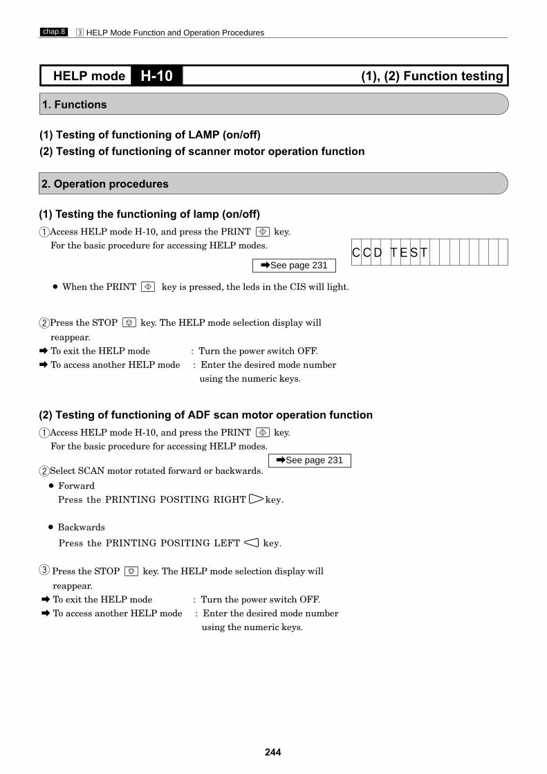
244
c HELP Mode Function and Operation Procedureschap.8
(1) Testing the functioning of lamp (on/off) qAccess HELP mode H-10, and press the PRINT key.
For the basic procedure for accessing HELP modes.
¡ When the PRINT key is pressed, the leds in the CIS will light.
wPress the STOP key. The HELP mode selection display will
reappear.a To exit the HELP mode : Turn the power switch OFF.a To access another HELP mode : Enter the desired mode number
using the numeric keys.
1. Functions
(1) Testing of functioning of LAMP (on/off) (2) Testing of functioning of scanner motor operation function
2. Operation procedures
H-10 (1), (2) Function testingHELP mode
\See page 231C C D T E S T
(2) Testing of functioning of ADF scan motor operation function qAccess HELP mode H-10, and press the PRINT key.
For the basic procedure for accessing HELP modes.
wSelect SCAN motor rotated forward or backwards.
¡ ForwardPress the PRINTING POSITING RIGHT key.
¡ Backwards
e
\See page 231
Press the STOP key. The HELP mode selection display will
reappear.a To exit the HELP mode : Turn the power switch OFF.a To access another HELP mode : Enter the desired mode number
using the numeric keys.
Press the PRINTING POSITING LEFT key.

245
c HELP Mode Function and Operation Procedureschap.8
w Select one of the items below, and follow the procedure given for it.
¡ Display of darkness value for lightest part of documenta Use the DOCUMENT MODE SWITCH key to select the
TEXT item. Feed a document to ADF.A value between 000 ("darkest" value) and 255 ("lightest" value)will be displayed.
¡ Display of darkness value for darkest part of document (relativeto lightest part, above)
a Use the DOCUMENT MODE SWITCH key to select thePHOTOGRAPH item. Feed a document to ADF.A value between 000 ("darkest" value) and 255 ("lightest" value)will be displayed.
1. Functions
(1) Document darkness values and scanner test (for usein factory checks)
(1) Document darkness values and scanner test (for usein factory checks)
qAccess HELP mode H-11, and press the PRINT key.For the basic procedure for accessing HELP modes.
¡ When the PRINT key is pressed, the CIS lights up and thedocument is conveyed to the "position for sensing document size".The sensed size is displayed as a 4-digit number (****) and thedocument is fed out.
2. Operation procedures
H-11 (1) Sensor/switch condition displayHELP mode
\See page 231
ePress the STOP key. The HELP mode selection display will
reappear.a To exit the HELP mode : Turn the power switch OFF.a To access another HELP mode : Enter the desired mode number
using the numeric keys.
Sensed size display
1 1 1 1P

246
c HELP Mode Function and Operation Procedureschap.8
ePress the STOP key. The HELP mode selection display willreappear.
a To exit the HELP mode : Turn the power switch OFF.a To access another HELP mode : Enter the desired mode number
using the numeric keys.
1. Functions
(1) Checking of shading memory.
(1) Checking of shading memory.
qAccess HELP mode H-12, and press the PRINT key.For the basic procedure for accessing HELP modes.
wSelect one of the items below, and follow the procedure given for it.¡ Check of shading memory, and display of resulta Press the DOCUMENT MODE SWITCH key as many times
as needed to select the TEXT item.An "S-RAM TEST OK" result display indicates the memory is normal. Any other display indicates abnormality.
2. Operation procedures
H-12 (1) Function testingHELP mode
¡ Check result display
\See page 231
S - R A M T E S T O K

247
c HELP Mode Function and Operation Procedureschap.8
1. Functions
(1) Checking of condition of switches listed below:¡ Display of amount of light received by end mark sensors
(1) Checking the condition of the listed switches
qAccess HELP mode H-13, and press the PRINT key.For the basic procedure for accessing HELP modes.
S End mark sensor2
¡Display of presence/absence of the master on its travel path, asa numerical value.
2. Operation procedures
H-13 (1) Sensor/switch condition displayHELP mode
\See page 231
End mark sensor
\See page 68,71
Amount of light received by endmark sensor1
Amount of light received byend mark sensor2
S End mark sensor1¡Display of presence/absence of the master on its travel path, as
a numerical value.<Sensitivity adjustment of the end mark sensor>Adjust the sensitivity using the driver to adjust end mark pcb.
Make sure that the difference between black and white is "30" orlarger.
wSelect the sensor below and follow the procedure accordingly.
ePress the STOP key. The HELP mode selection display willreappear.
a To exit the HELP mode : Turn the power switch OFF.a To access another HELP mode : Enter the desired mode number
using the numeric keys.
A : 1 1
B : 1 1A : 1 1
B : 1 1
Adjust the sensitivity using the driver to adjust end mark pcb.
Set the white level to "0-10" and black level to "45-63".
Make sure that the difference between black and white is "30" orlarger.
Press and hold down TEST PRINT key to feed master slowly.
Press and hold down TEST PRINT key to feed master slowly.
Set the white level 10 and black level >50.<

248
c HELP Mode Function and Operation Procedureschap.8
(1) Mastermaking total counter displayqAccess HELP mode H-14, and press the PRINT key.
For the basic procedure for accessing HELP modes.
When the PRINT key is pressed, the total number of mastermaking is displayed.
1. Functions
(1) Mastermaking total counter display(2) Resetting of count of total masters made in user mode
wPress the STOP key. The HELP mode selection display will
reappear.a To exit the HELP mode : Turn the power switch OFF.a To access another HELP mode : Enter the desired mode number
using the numeric keys.
2. Operation procedures
H-14 (1) Total countsHELP mode
\See page 231
(2) Resetting the count of total masters made in user mode
qAccess HELP mode H-14, and press the PRINT key.For the basic procedure for accessing HELP mode.
¡When the PRINT key is pressed, the current value for thecount of total masters made in user mode will be displayed.
wPress the [=] key and CLEAR keys simultaneously, to
execute resetting. The resetting will be memorized in the main PCB unit's EEPROM.
C
ePress the STOP key. The HELP mode selection display will
reappear.a To exit the HELP mode : Turn the power switch OFF.a To access another HELP mode : Enter the desired mode number
using the numeric keys.
\See page 231
[F] = mastermaking
Mastermaking total counter
F 1 1 1 1 1 1 1 1

249
c HELP Mode Function and Operation Procedureschap.8
1. Functions
(1) Function testing of ink motor
1) Testing the functioning of the ink motor
qAccess HELP mode H-15, and press the PRINT key.For the basic procedure for accessing HELP modes
wPress and hold the TEST PRINT key. The ink motor will run
for as long as the key is held down.
¡ Remember that ink will be delivered when the ink motor runs.Take any precautions necessary.
T
eRelease the TEST PRINT key. The ink motor will stop.T
2. Operation procedures
H-15 (1) Function testingHELP mode
IMPORTANT
\See page 231
rPress the STOP key. The HELP mode selection display will
reappear.a To exit the HELP mode : Turn the power switch OFF.a To access another HELP mode : Enter the desired mode number
using the numeric keys.
I N K M O T O R . T E S T

250
c HELP Mode Function and Operation Procedureschap.8
1. Functions
ABCD Item Setting
0***Sign flag
Rises by the set amount for thelower 3 digits
1***Lowers by the set amount for thelower 3 digits
*000
Set amount
Standard (initial value)
Maximum
*001
*010
*011
*100
*101
*110
*111
Correction amount display
(1) Setting of online (with PC interface) mastermakingstart position.
qAccess HELP mode H-16, and press the PRINT key.For the basic procedure for accessing HELP modes.
wUse the [0] and [1] numeric keys to enter a 4-place binary value for
the desired correction amount. See the table below for 4-placebinary values and the corresponding correction amounts.
2. Operation procedures
H-16 (1) Adjustment / specification settingHELP mode
rPress the STOP key. The HELP mode selection display will reappear.a To exit the HELP mode : Turn the power switch OFF.a To access another HELP mode : Enter the desired mode number using the numeric keys.
ePress the [=] key. The correction amount will be memorized
in the main PCB unit's EEPROM. During memorization,"SAVE" will be displayed.
Do not turn off the power before the "SAVE" display has disappeared.
IMPORTANT
\See page 231
For Standards / Adjustment
\See page 184
Related HELP mode
HELP mode H-37 \See page 269
HELP mode H-53 \See page 276
Sign flag
A : 1 B : 1 C : 1 D : 1
¡During memorization:
1 1 1 S A V E 1 1 1
(1) Setting of online (with PC interface) mastermakingstart position.

251
c HELP Mode Function and Operation Procedureschap.8
1. Functions
(1) Function testing of cutter motor
(1) Testing the functioning of the cutter motor
qAccess HELP mode H-17, and press the PRINT key.For the basic procedure for accessing HELP modes.
wPress and hold down the PRINT POSITION ADJUST key. The
cutter will go to the no-operation side when right key is held on,
eTo stop the motor (and the roller), release the PRINT POSITION
2. Operation procedures
H-17 (1) Function testingHELP mode
\See page 231
rPress the STOP key. The HELP mode selection display will
reappear.a To exit the HELP mode : Turn the power switch OFF.a To access another HELP mod : Enter the desired mode number
using the numeric keys.
For desccription of operation
\See page 72
C U T T E R M T R T E S T
and will come back to the operation side when left key is held on.
ADJUST key.

252
c HELP Mode Function and Operation Procedureschap.8
1. Functions
(1) Function testing of roll-up motor
(1) Testing the functioning of the roll-up motor
qAccess HELP mode H-18, and press the PRINT key.For the basic procedure for accessing HELP modes.
w
Press and hold down the PRINT POSITION ADJUSTENT RIGHT key.
The take-up motor will rotate in the reverse direction (counterclockwise), so that the roller inside the master ejection box turns, for as long as thekey is held down.
eTo stop the motor (and the roller), release the PRINT POSITION
ADJUSTMENT key.
2. Operation procedures
H-18 (1) Function testingHELP mode
\See page 231
rPress the STOP key. The HELP mode selection display will
reappear.a To exit the HELP mode : Turn the power switch OFF.a To access another HELP mod : Enter the desired mode number
using the numeric keys.
For desccription of operation
\See page 77
E J E C T M O T O R T E S T
F A N M O T O R T E S T
(2) Function testing the of the fan motor
(2) Testing the functioning of the fan motor
Select TEXT mode by pressing the DOCUMENT MODE SELECT key.
w
Press and hold down the PRINT POSITION ADJUSTMENT RIGHT key.
The fan motor will rotate, so that it will inhale.for as long as the key isheld down.
eTo stop the motor (and the roller), release the PRINT POSITION
ADJUSTMENT key.
qAccess HELP mode H-18, and press the PRINT key.For the basic procedure for accessing HELP modes.
\See page 231
Select PHOTOGRAPH or TEXT/PHOTOGRAPH mode by pressing the DOCUMENT MODE SELECT key.

253
c HELP Mode Function and Operation Procedureschap.8
(2) Resetting the count of total sheets printed in user mode
qAccess HELP mode H-19, and press the PRINT key.For the basic procedure for accessing HELP modes.
¡When the PRINT key is pressed, the current value for thecount of total sheets printed in user mode will be displayed.
\See page 231
1. Functions
(1) Printing total counter display(2) Resetting of count of total sheets printed in user
mode
H-19 (1) Total countsHELP mode
2. Operation procedures
(1) 8-digit display of count of total sheets printed
qAccess HELP mode H-19, and press the PRINT key.For the basic procedure for accessing HELP modes.
"P"=Print
\See page 231
wPress the STOP key. The HELP mode selection display will
reappear.a To exit the HELP mode : Turn the power switch OFF.a To access another HELP mode : Enter the desired mode number
using the numeric keys.
¡When the PRINT key is pressed, the total number of print isdisplayed.
Printing total counter
ePress the STOP key. The HELP mode selection display will
reappear.a To exit the HELP mode : Turn the power switch OFF.a To access another HELP mode : Enter the desired mode number
using the numeric keys.
wPress the [=] key and CLEAR keys keys simultaneously,
to execute resetting. The resetting will be memorized in thebattery PCB unit's EEPROM.
C
P 1 1 1 1 1 1 1 1

254
c HELP Mode Function and Operation Procedureschap.8
¡Whether the clamp is in the A, B or C mode position is determined by the B mode sensor and the A/C modesensor in combination:
A mode position : When the light beam of both the B mode and A/C mode sensor is unobstructed.C mode position : When the light beam of both the B mode sensor is obstructed and that of the A/C mode
sensor unobstructed.B mode position : When the B mode sensor senses edge, and the light beam of the A/C mode sensor is
obstructed.¡If the clamp is not in the A mode position when the power is turned on, it will rotate to the B position and stop
there.
wPress and hold down the PRINT POSITION RIGHT key. The clamp
motor will rotate in the reverse direction (counterclockwise), opening outthe clamp, for as long as the key is held down.
eTo stop opening of the clamp, release the PRINT POSITION RIGHT
key. (Alternatively, opening will stop automatically when thelight beam of the A/C mode sensor (PS3) is restored).
rPress and hold down the PRINT POSITION LEFT key. The clamp motor will
rotate in the regular direction (clockwise), closing the clamp, for aslong as the key is held down.
tTo stop closing of the clamp, release the PRINT POSITION LEFT key.
(Alternatively, closing will stop automatically when the light beam ofthe A/C mode sensor (PS3) is restored).
1. Functions
(1) Function testing of clamp motor and clamp positionsensing (A/B/C mode position)
(1) Testing the functioning of the clamp motor andclamp position sensing (A/B/C mode position)
qAccess HELP mode H-20, and press the PRINT key.For the basic procedure for accessing HELP modes.
yPress the STOP key. The HELP mode selection display will
reappear.a To exit the HELP mode : Turn the power switch OFF.a To access another HELP mode : Enter the desired mode number
using the numeric keys.
2. Operation procedures
H-20 (1) Function testingHELP mode
NOTE
For Standards / Adjustment
\See page 165
For Standards / Adjustment
\See page 167
B mode
A /C mode
For desccription of operation
\See page 76
C L A M P M O T O R T E S T
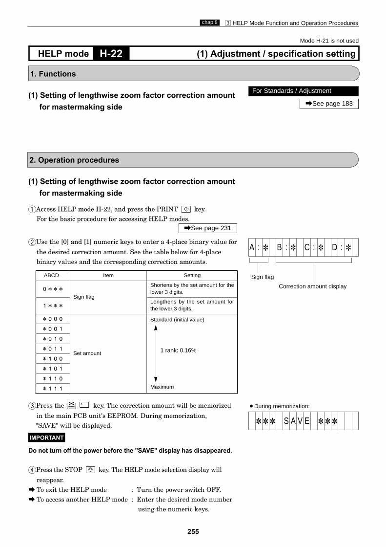
255
c HELP Mode Function and Operation Procedureschap.8
H-22 (1) Adjustment / specification settingHELP mode
1. Functions
(1) Setting of lengthwise zoom factor correction amountfor mastermaking side
2. Operation procedures
ABCD Item Setting
0***Sign flag
Shortens by the set amount for thelower 3 digits.
1***Lengthens by the set amount forthe lower 3 digits.
*000
Set amount
Standard (initial value)
Maximum
*001
*010
*011
*100
*101
*110
*111
(1) Setting of lengthwise zoom factor correction amountfor mastermaking side
qAccess HELP mode H-22, and press the PRINT key.For the basic procedure for accessing HELP modes.
wUse the [0] and [1] numeric keys to enter a 4-place binary value for
the desired correction amount. See the table below for 4-placebinary values and the corresponding correction amounts.
rPress the STOP key. The HELP mode selection display will
reappear.a To exit the HELP mode : Turn the power switch OFF.a To access another HELP mode : Enter the desired mode number
using the numeric keys.
ePress the [=] key. The correction amount will be memorized
in the main PCB unit's EEPROM. During memorization, "SAVE" will be displayed.
Do not turn off the power before the "SAVE" display has disappeared.
IMPORTANT
\See page 231
1 rank: 0.16%
For Standards / Adjustment
\See page 183
Mode H-21 is not used
Correction amount display
Sign flag
A : 1 B : 1 C : 1 D : 1
¡During memorization:
1 1 1 S A V E 1 1 1

256
c HELP Mode Function and Operation Procedureschap.8
H-23 (1) Adjustment / specification settingHELP mode
1. Functions
(1) Setting of photograph mode document sensingdarkness
2. Operation procedures
(1) Setting of photograph mode document sensingdarkness
qAccess HELP mode H-23, and press the PRINT key.For the basic procedure for accessing HELP modes.
wUse the [0] and [1] numeric keys to enter a 4-place binary value for
the desired correction amount. See the table below for 4-placebinary values and the corresponding correction amounts.
\See page 231
For Standards / Adjustment
\See page 186
Related HELP mode
HELP mode H-50 \See page 276
rPress the STOP key. The HELP mode selection display will
reappear.a To exit the HELP mode : Turn the power switch OFF.a To access another HELP mode : Enter the desired mode number
using the numeric keys.
ePress the [=] key. The correction amount will be memorized
in the main PCB unit's EEPROM. During memorization, "SAVE" will be displayed.
Do not turn off the power before the "SAVE" display has disappeared.
IMPORTANT
ABCD Item Setting
0***Sign flag
1***
*000
Set amount
Standard (initial value)
Maximum
*001
*010
*011
*100
*101
*110
*111
Correction amount display
Sign flag
A : 1 B : 1 C : 1 D : 1
¡During memorization:
1 1 1 S A V E 1 1 1
Correction amount display
Sign flag
E : 1 F : 1 G : 1 H : 1
Setting for ADF(When PHOTOGRAPH or
TEXT/PHOTOGRAPH mode is set)
Rises by the set amount for thelower 3 digits
Lowers by the set amount for thelower 3 digits

257
c HELP Mode Function and Operation Procedureschap.8
H-24 (1) Adjustment / specification settingHELP mode
1. Functions
(1) Setting of reducing offset for reading longitudinalR/E scanner
2. Operation procedures
ABCD Item Setting
0000
Set amount
Standard (initial value)
Maximum
0001
0010
0011
•••••
1111
•If help mode H-24 setting is required, HELP mode H-25 must be set to "0000".
(1) Setting of reducing offset for reading longitudinalR/E scanner
qAccess HELP mode H-24, and press the PRINT key.For the basic procedure for accessing HELP modes.
wUse the [0] and [1] numeric keys to enter a 4-place binary value for
the desired correction amount. See the table below for 4-placebinary values and the corresponding correction amounts.
rPress the STOP key. The HELP mode selection display will reappear.a To exit the HELP mode : Turn the power switch OFF.a To access another HELP mode : Enter the desired mode number using the numeric keys.
ePress the [=] key. The correction amount will be memorized
in the main PCB unit's EEPROM. During memorization,"SAVE" will be displayed.
Do not turn off the power before the "SAVE" display has disappeared.
IMPORTANT
\See page 231
1 rank: 0.25%
For Standards / Adjustment
\See page 183
Related HELP mode
HELP mode H-25 \See page 258
During memorization:
1 1 1 S A V E 1 1 1
Correction amount display
A : 1 B : 1 C : 1 D : 1
Correction amount display
Sign flag
E : 1 F : 1 G : 1 H : 1
Setting for ADF(When PHOTOGRAPH or
TEXT/PHOTOGRAPH mode is set)

258
c HELP Mode Function and Operation Procedureschap.8
H-25 (1) Adjustment / specification settingHELP mode
1. Functions
(1) Setting of enlarging offset for reading longitudinalR/E of scanner
2. Operation procedures
ABCD Item Setting
0000
Set amount
Standard (initial value)
Maximum
0001
0010
0011
•••••
1111
•If help mode H-25 setting is required, HELP mode H-24 must be set to "0000".
(1) Setting of enlarging offset for reading longitudinalR/E of scanner
qAccess HELP mode H-25, and press the PRINT key.For the basic procedure for accessing HELP modes.
wUse the [0] and [1] numeric keys to enter a 4-place binary value for
the desired correction amount. See the table below for 4-placebinary values and the corresponding correction amounts.
rPress the STOP key. The HELP mode selection display will reappear.a To exit the HELP mode : Turn the power switch OFF.a To access another HELP mode : Enter the desired mode number using the numeric keys.
\See page 231
For Standards / Adjustment
\See page 183
Related HELP mode
HELP mode H-24 \See page 257
ePress the [=] key. The correction amount will be memorized
in the main PCB unit's EEPROM. During memorization,"SAVE" will be displayed.
Do not turn off the power before the "SAVE" display has disappeared.
IMPORTANT
¡During memorization:
1 1 1 S A V E 1 1 1
Correction amount display
A : 1 B : 1 C : 1 D : 1
Correction amount display
Sign flag
E : 1 F : 1 G : 1 H : 1
Setting for ADF(When PHOTOGRAPH or
TEXT/PHOTOGRAPH mode is set)
1 rank: 0.25%
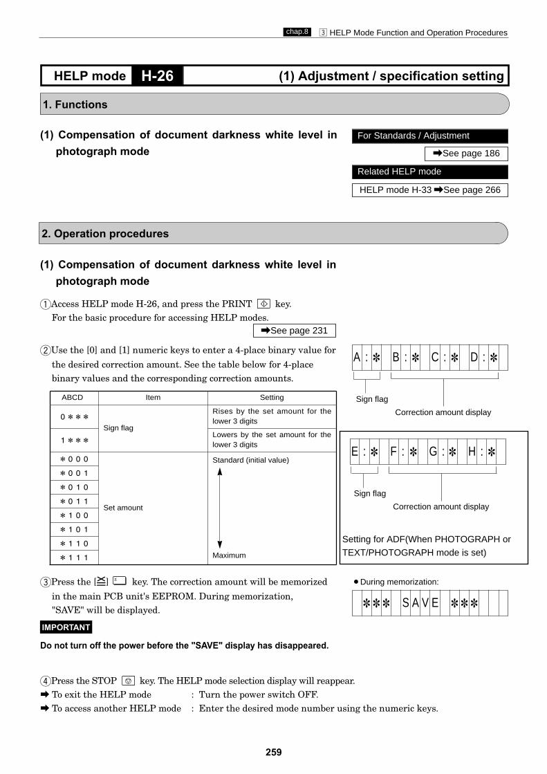
259
c HELP Mode Function and Operation Procedureschap.8
H-26 (1) Adjustment / specification settingHELP mode
1. Functions
(1) Compensation of document darkness white level inphotograph mode
2. Operation procedures
ABCD Item Setting
0***Sign flag
Rises by the set amount for thelower 3 digits
1***Lowers by the set amount for thelower 3 digits
*000
Set amount
Standard (initial value)
Maximum
*001
*010
*011
*100
*101
*110
*111
(1) Compensation of document darkness white level inphotograph mode
qAccess HELP mode H-26, and press the PRINT key.For the basic procedure for accessing HELP modes.
wUse the [0] and [1] numeric keys to enter a 4-place binary value for
the desired correction amount. See the table below for 4-placebinary values and the corresponding correction amounts.
rPress the STOP key. The HELP mode selection display will reappear.a To exit the HELP mode : Turn the power switch OFF.a To access another HELP mode : Enter the desired mode number using the numeric keys.
\See page 231
For Standards / Adjustment
\See page 186
Related HELP mode
HELP mode H-33 \See page 266
ePress the [=] key. The correction amount will be memorized
in the main PCB unit's EEPROM. During memorization,"SAVE" will be displayed.
Do not turn off the power before the "SAVE" display has disappeared.
IMPORTANT
¡During memorization:
1 1 1 S A V E 1 1 1
Correction amount display
Sign flag
A : 1 B : 1 C : 1 D : 1
Correction amount display
Sign flag
E : 1 F : 1 G : 1 H : 1
Setting for ADF(When PHOTOGRAPH or
TEXT/PHOTOGRAPH mode is set)

260
c HELP Mode Function and Operation Procedureschap.8
H-27 (1) Adjustment / specification settingHELP mode
1. Functions
(1) Initialization of all HELP mode settings
(1) Initializing all the HELP mode settings
qAccess HELP mode H-27, and press the PRINT key.For the basic procedure for accessing HELP modes.
wPress the [=] key. The adjustment and specification settings
of the HELP modes will be initialized. (But for the total counts (H-14 and H-19), only the user mode values will be initialized.) Whileinitialization is in progress, "SAVE" will be displayed.
¡ Do not turn off the power before the "SAVE" display has disappeared.
¡ For the values after initialization, see the initialization values foreach mode, and the HELP decals (on the inside of the rear cover).
¡ After initialization, carry out the adjustment and specificationsetting operations for the various modes. Inappropriate settingswill results in operational problems.
2. Operation procedures
IMPORTANT
ePress the STOP key. The HELP mode selection display will
reappear.a To exit the HELP mode : Turn the power switch OFF.a To access another HELP mode : Enter the desired mode number
using the numeric keys.
IMPORTANT
\See page 231
: I N I T I A L I Z E
¡During memorization:
1 1 1 S A V E 1 1 1
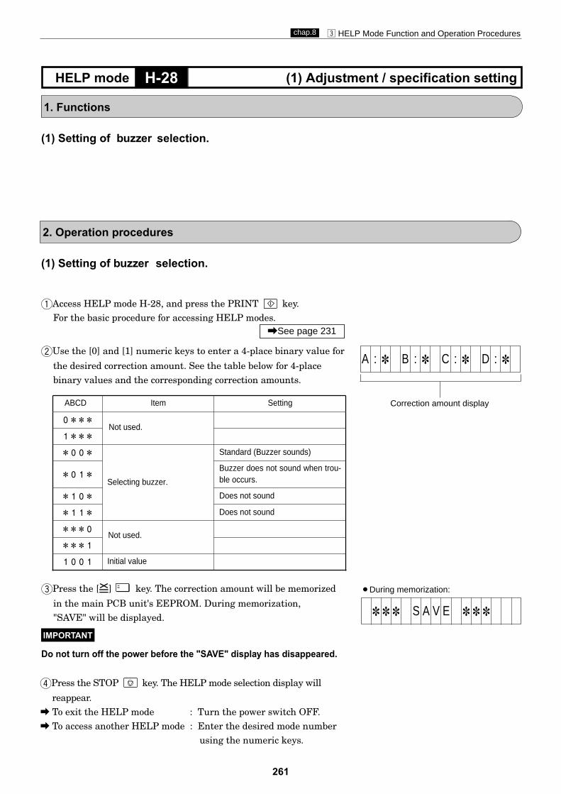
261
c HELP Mode Function and Operation Procedureschap.8
H-28 (1) Adjustment / specification settingHELP mode
1. Functions
(1) Setting of buzzer selection.
2. Operation procedures
ABCD Item Setting
0***
1***
*00*
Selecting buzzer.
Standard (Buzzer sounds)
*01*Buzzer does not sound when trou-ble occurs.
*10* Does not sound
*11* Does not sound
***0
***1
1001 Initial value
(1) Setting of buzzer selection.
qAccess HELP mode H-28, and press the PRINT key.For the basic procedure for accessing HELP modes.
wUse the [0] and [1] numeric keys to enter a 4-place binary value for
the desired correction amount. See the table below for 4-placebinary values and the corresponding correction amounts.
ePress the [=] key. The correction amount will be memorized
in the main PCB unit's EEPROM. During memorization,"SAVE" will be displayed.
Do not turn off the power before the "SAVE" display has disappeared.
IMPORTANT
\See page 231
rPress the STOP key. The HELP mode selection display will
reappear.a To exit the HELP mode : Turn the power switch OFF.a To access another HELP mode : Enter the desired mode number
using the numeric keys.
¡During memorization:
1 1 1 S A V E 1 1 1
Correction amount display
A : 1 B : 1 C : 1 D : 1
Not used.
Not used.
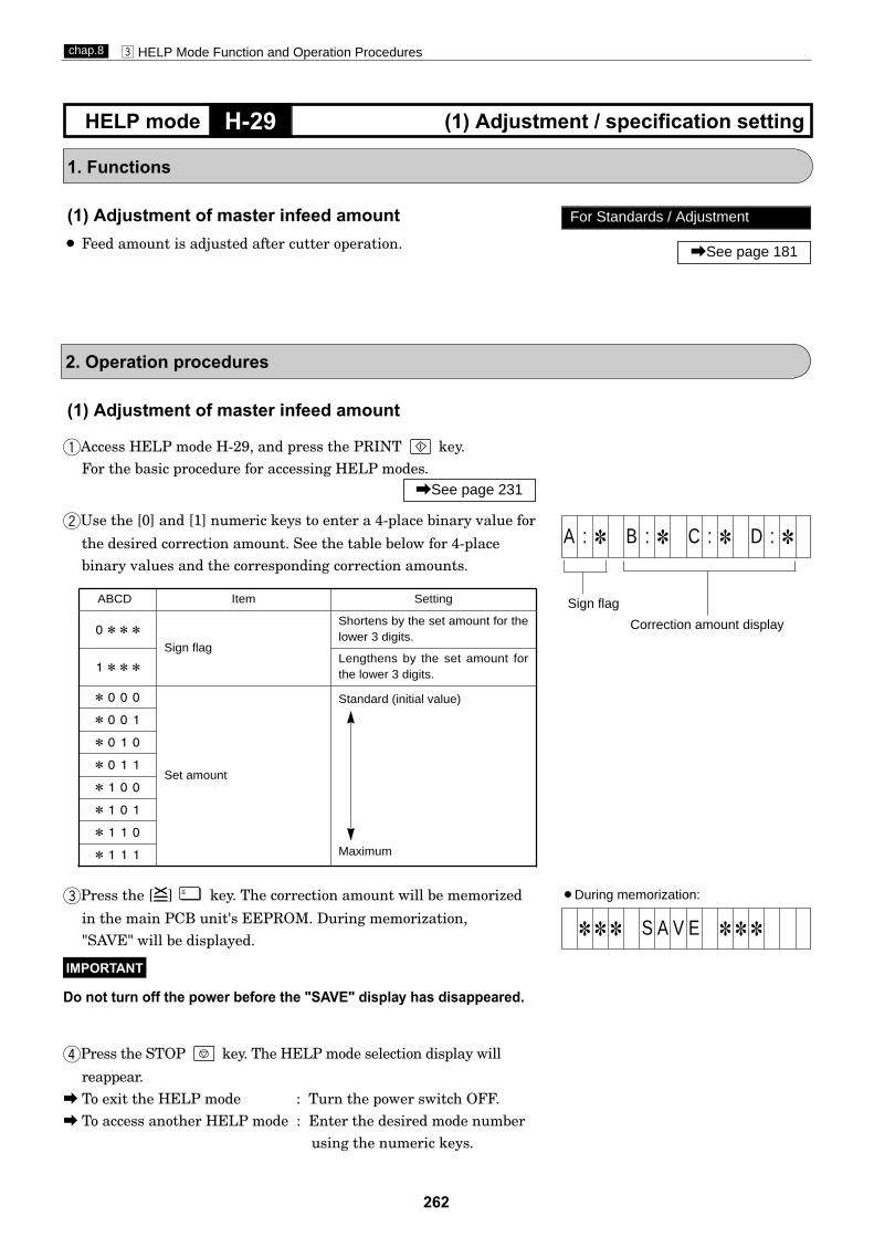
262
c HELP Mode Function and Operation Procedureschap.8
H-29 (1) Adjustment / specification settingHELP mode
1. Functions
(1) Adjustment of master infeed amount¡ Feed amount is adjusted after cutter operation.
2. Operation procedures
ABCD Item Setting
0***Sign flag
Shortens by the set amount for thelower 3 digits.
1***Lengthens by the set amount forthe lower 3 digits.
*000
Set amount
Standard (initial value)
Maximum
*001
*010
*011
*100
*101
*110
*111
(1) Adjustment of master infeed amount
qAccess HELP mode H-29, and press the PRINT key.For the basic procedure for accessing HELP modes.
wUse the [0] and [1] numeric keys to enter a 4-place binary value for
the desired correction amount. See the table below for 4-placebinary values and the corresponding correction amounts.
rPress the STOP key. The HELP mode selection display will
reappear.a To exit the HELP mode : Turn the power switch OFF.a To access another HELP mode : Enter the desired mode number
using the numeric keys.
ePress the [=] key. The correction amount will be memorized
in the main PCB unit's EEPROM. During memorization,"SAVE" will be displayed.
Do not turn off the power before the "SAVE" display has disappeared.
IMPORTANT
\See page 231
For Standards / Adjustment
\See page 181
¡During memorization:
1 1 1 S A V E 1 1 1
Correction amount display
Sign flag
A : 1 B : 1 C : 1 D : 1

263
c HELP Mode Function and Operation Procedureschap.8
1. Functions
(1) Test pattern (all shading, secondary scanningdirection zoom factor adjustment) mastermaking andprinting
2. Operation procedures
H-30 (1) Function checkingHELP mode
For adjusting reduction / enlargement
\See page 183
ePress the MASTERMAKING key to implement mastermaking/printing
rPress the STOP key. The HELP mode selection display will
reappear.a To exit the HELP mode : Turn the power switch OFF.a To access another HELP mode : Enter the desired mode number
using the numeric keys.
0 s h t 1 s e t
(1) Test pattern (all shading, poor image area checking,secondary scanning direction zoom factor adjustment)mastermaking and printing
qAccess HELP mode H-30, and press the PRINT key.For the basic procedure for accessing HELP modes.
wSelect one of the items below, and follow the procedure given for it.¡ Test pattern 1 (all shading)aUse the DOCUMENT MODE SWITCH key to select the
PHOTOGRAPH item.
¡Test pattern 3 (secondary scanning direction zoom factor adjustment)aUse the DOCUMENT MODE SWITCH key to select the
TEXT item.
¡Test pattern 1
¡Test pattern 2
\See page 231
¡ Once this mode has been entered, it is not possible to switch toany other mode. To exit this mode, turn off the power.
IMPORTANT
¡Test pattern 3
¡ Test pattern 2 (secondary scanning direction mastermaking area adjustment)aUse the DOCUMENT MODE SWITCH key to select the
TEXT/PHOTOGRAPH item.

264
c HELP Mode Function and Operation Procedureschap.8
H-31 (1) Adjustment / specification settingHELP mode
1. Functions
(1) Setting of number of pre-print sheetsUse this to set a value for the number of pre-print sheets. "Pre-print sheets" are extra sheets that are printed at the start ofprinting, without being added to the print count.
2. Operation procedures
ABCD
0000
0001
0010
0011
0100
0101
0110
0111
ABCD
1000
1001
1010
1011
1100
1101
1110
1111
Item
8 sheets
9 sheets
10 sheets
11 sheets
12 sheets
13 sheets
14 sheets
15 sheets
Item
0 sheet(initial value)
1 sheet
2 sheets
3 sheets
4 sheets
5 sheets
6 sheets
7 sheets
(1) Setting of number of pre-print sheets
qAccess HELP mode H-31, and press the PRINT key.For the basic procedure for accessing HELP modes.
wUse the [0] and [1] numeric keys to enter a 4-place binary value for
the desired correction amount. See the table below for 4-placebinary values and the corresponding correction amounts.
ePress the [=] key. The correction amount will be memorized
"SAVE" will be displayed.
Do not turn off the power before the "SAVE" display has disappeared.
IMPORTANT
\See page 231
rPress the STOP key. The HELP mode selection display will
reappear.a To exit the HELP mode : Turn the power switch OFF.a To access another HELP mode : Enter the desired mode number
using the numeric keys.
Correction amount display
A : 1 B : 1 C : 1 D : 1
¡During memorization:
1 1 1 S A V E 1 1 1into the main PCB unit's EEPROM. During memorization,

265
c HELP Mode Function and Operation Procedureschap.8
H-32 (1) Adjustment / specification settingHELP mode
1. Functions
(1) Confidential safeguard function, selection of firstprint speed, setting of master ejection error sensing
2. Operation procedures
ABCD Item Setting
0*** Disabled
Enabled1***
*0** 1st-speed (about 45 rpm)
*1** JOG speed (about 15 rpm)
**0* Enabled
**1* Disabled
***0 Not used. ***1
1000 Initial value
Confidential safeguard function
Selecting the first print speed. /Selecting the print speed for the first sheet after mastermaking is com-pleted.
Master mis-ejection detec-tion
(1) Confidential safeguard function, selection of firstprint speed, setting of master ejection error sensing
qAccess HELP mode H-32, and press the PRINT key.For the basic procedure for accessing HELP modes.
wUse the [0] and [1] numeric keys to enter a 4-place binary value for
the desired correction amount. See the table below for 4-placebinary values and the corresponding correction amounts.
ePress the [=] key. The correction amount will be memorized
"SAVE" will be displayed.
Do not turn off the power before the "SAVE" display has disappeared.
IMPORTANT
\See page 231
rPress the STOP key. The HELP mode selection display will
reappear.a To exit the HELP mode : Turn the power switch OFF.a To access another HELP mode : Enter the desired mode number
using the numeric keys.
Correction amount display
A : 1 B : 1 C : 1 D : 1
¡During memorization:
1 1 1 S A V E 1 1 1into the main PCB unit's EEPROM. During memorization,

266
c HELP Mode Function and Operation Procedureschap.8
H-33 (1) Adjustment / specification settingHELP mode
1. Functions
(1) Compensation of document darkness white level intext mode
2. Operation procedures
ABCD Item Setting
0***Sign flag
Rises by the set amount for thelower 3 digits
1***Lowers by the set amount for thelower 3 digits
*000
Set amount
Standard (initial value)
Maximum
*001
*010
*011
*100
*101
*110
*111
(1) Compensation of document darkness white level intext mode
qAccess HELP mode H-33, and press the PRINT key.For the basic procedure for accessing HELP modes.
wUse the [0] and [1] numeric keys to enter a 4-place binary value for
the desired correction amount. See the table below for 4-placebinary values and the corresponding correction amounts.
rPress the STOP key. The HELP mode selection display will reappear.a To exit the HELP mode : Turn the power switch OFF.a To access another HELP mode : Enter the desired mode number
using the numeric keys.
ePress the [=] key. The correction amount will be memorized
"SAVE" will be displayed.
Do not turn off the power before the "SAVE" display has disappeared.
IMPORTANT
\See page 231
For Standards / Adjustment
\See page 186
Related HELP mode
HELP mode H-26 \See page 259
¡During memorization:
1 1 1 S A V E 1 1 1
Correction amount display
Sign flag
A : 1 B : 1 C : 1 D : 1
into the main PCB unit's EEPROM. During memorization,
Correction amount display
Sign flag
E : 1 F : 1 G : 1 H : 1
Setting for ADF(When PHOTOGRAPH or
TEXT/PHOTOGRAPH mode is set)

267
c HELP Mode Function and Operation Procedureschap.8
H-35 (1) Adjustment / specification settingHELP mode
1. Functions
Mode H-34 is not used
(1) Adjustment of scanner leading edge sensing position
2. Operation procedures
ABCD Item Setting
0***Sign flag
Moves to the left by the setamount of the lower 3 digits.
1***Moves to the right by the setamount of the lower 3 digits.
*000
Set amount
Standard (initial value)
Maximum
*001
*010
*011
*100
*101
*110
*111
(1) Scanner leading edge sensing position adjustment
qAccess HELP mode H-35, and press the PRINT key.For the basic procedure for accessing HELP modes.
wUse the [0] and [1] numeric keys to enter a 4-place binary value for
the desired correction amount. See the table below for 4-placebinary values and the corresponding correction amounts.
rPress the STOP key. The HELP mode selection display will
reappear.a To exit the HELP mode : Turn the power switch OFF.a To access another HELP mode : Enter the desired mode number
using the numeric keys.
ePress the [=] key. The correction amount will be memorized
"SAVE" will be displayed.
Do not turn off the power before the "SAVE" display has disappeared.
IMPORTANT
\See page 231
For Standards / Adjustment
\See page 184
Related HELP mode
HELP mode H-36 \See page 268
Correction amount display
Sign flag
A : 1 B : 1 C : 1 D : 1
¡During memorization:
1 1 1 S A V E 1 1 1into the main PCB unit's EEPROM. During memorization,
Correction amount display
Sign flag
E : 1 F : 1 G : 1 H : 1
Setting for ADF(When PHOTOGRAPH or
TEXT/PHOTOGRAPH mode is set)

268
c HELP Mode Function and Operation Procedureschap.8
H-36 (1) Adjustment / specification settingHELP mode
1. Functions
(1) Adjustment of scanner widthwise (operation side)
2. Operation procedures
ABCD Item Setting
0***Sign flag
Moves toward you by the setamount of the lower 3 digits.
1***Moves backward by the setamount of the lower 3 digits.
*000
Set amount
Standard (initial value)
Maximum
*001
*010
*011
*100
*101
***1
*111
(1) Scanner widthwise (operation side) sensing positionadjustment
qAccess HELP mode H-36, and press the PRINT key.For the basic procedure for accessing HELP modes.
wUse the [0] and [1] numeric keys to enter a 4-place binary value for
the desired correction amount. See the table below for 4-placebinary values and the corresponding correction amounts.
ePress the [=] key. The correction amount will be memorized
"SAVE" will be displayed.
Do not turn off the power before the "SAVE" display has disappeared.
IMPORTANT
\See page 231
For Standards / Adjustment
\See page 184
Related HELP mode
HELP mode H-35 \See page 267
rPress the STOP key. The HELP mode selection display will
reappear.a To exit the HELP mode : Turn the power switch OFF.a To access another HELP mode : Enter the desired mode number
using the numeric keys.
Correction amount display
Sign flag
A : 1 B : 1 C : 1 D : 1
¡During memorization:
1 1 1 S A V E 1 1 1into the main PCB unit's EEPROM. During memorization,
Correction amount display
Sign flag
E : 1 F : 1 G : 1 H : 1
Setting for ADF(When PHOTOGRAPH or
TEXT/PHOTOGRAPH mode is set)
sensing position

269
c HELP Mode Function and Operation Procedureschap.8
H-37 (1) Adjustment / specification settingHELP mode
1. Functions
(1) Adjustment of mastermaking start position whenscanner is used
2. Operation procedures
ABCD Item Setting
0***Sign flag
Rises by the set amount for thelower 3 digits
1***Lowers by the set amount for thelower 3 digits
*000
Set amount
Standard (initial value)
Maximum
*001
*010
*011
*100
*101
*110
*111
(1) Adjustment of mastermaking start position whenscanner is used
qAccess HELP mode H-37, and press the PRINT key.For the basic procedure for accessing HELP modes.
wUse the [0] and [1] numeric keys to enter a 4-place binary value for
the desired correction amount. See the table below for 4-placebinary values and the corresponding correction amounts.
ePress the [=] key. The correction amount will be memorized
"SAVE" will be displayed.
Do not turn off the power before the "SAVE" display has disappeared.
IMPORTANT
\See page 231
For Standards / Adjustment
\See page 185
Related HELP mode
HELP mode H-16 \See page 250
rPress the STOP key. The HELP mode selection display will
reappear.a To exit the HELP mode : Turn the power switch OFF.a To access another HELP mode : Enter the desired mode number
using the numeric keys.
Correction amount display
Sign flag
A : 1 B : 1 C : 1 D : 1
¡During memorization:
1 1 1 S A V E 1 1 1into the main PCB unit's EEPROM. During memorization,
Correction amount display
Sign flag
E : 1 F : 1 G : 1 H : 1
Setting for ADF(When PHOTOGRAPH or
TEXT/PHOTOGRAPH mode is set)

270
c HELP Mode Function and Operation Procedureschap.8
H-38 (1) Function testingHELP mode
qAccess HELP mode H-38, and press the PRINT key.
¡The drum rotates
w
ePress the STOP key. The HELP mode selection display will
reappear.a To exit the HELP mode: Turn the power switch OFF.a To access another HELP mode: Enter the desired mode number
using the numeric keys.
\See page 233
1. Functions
2. Operation procedures
For Standards / Adjustment
\See page 188
Related HELP mode
HELP mode H-01 \See page 234
For the basic procedure for accessing HELP modes.
\See page 231
It will adjust speed of drum rotation automatically within 1 min.
Do not turn off the power before the "SAVE" display has disappeared.
IMPORTANT
Correction amount display
S P E E D 1 - 7
Before this operation, you must set drum accurately first.
¡During memorization:
1 1 1 S A V E 1 1 1
(1)Adjustment of print speed automatically.

271
c HELP Mode Function and Operation Procedureschap.8
H-39HELP mode
1. Functions
(1) Function testing of clutch test and Auto power off
2. Operation procedures
(1) Correction of outline highlight when scanner is used
qAccess HELP mode H-39, and press the PRINT key.For the basic procedure for accessing HELP modes.
w
e
IMPORTANT
\See page 231
Press the STOP key. The HELP mode selection display will
reappear.a To exit the HELP mode : Turn the power switch OFF.a To access another HELP mode : Enter the desired mode number
using the numeric keys.
Correction amount display
C L U T C H T E S T
(1) Function checking
a Use the DOCUMENT MODE SWITCH key to select theTEXT item.
a Use the DOCUMENT MODE SWITCH key to select thePHOTOGRAPH/TEXT item.
Use these keys to test each function.
Press and hold down the PRINT POSITION ADJUST RIGHT key. The ADF clutch will be on, for as long as the key is held down.
Press and hold down the PRINT POSITION ADJUST RIGHT key. The Mater feed clutch will be on, for as long as the key is held down.
a Use the DOCUMENT MODE SWITCH key to select thePHOTOGRAPH item. Press and hold down the PRINT POSITION ADJUST RIGHT key. The Paper feed clutch will be on, for as long as the key is held down.
Use the TEST PRINT key to test the function of Auto power off.a
Please do not press the key for long time,It would be injured.

272
c HELP Mode Function and Operation Procedureschap.8
H-41 (1) Adjustment / specification settingHELP mode
1. Functions
(1) Automatic initialization of the control panel setting,Energy save mode setting
2. Operation procedures
ABCD Item Setting
0*** No automatic iniialization
1*** Initialized in about 2 minutes
*0**Energy save mode setting
*1**
**0*Count repeat display
Repeat display of count
**1* No repeat display of count
0000 Initial value
Automatic initialization of the control panel setting
(1) Automatic initialization of the control panel setting,setting of repeat count display
qAccess HELP mode H-41, and press the PRINT key.For the basic procedure for accessing HELP modes.
wUse the [0] and [1] numeric keys to enter a 4-place binary value for
the desired correction amount. See the table below for 4-placebinary values and the corresponding correction amounts.
\See page 231
ePress the [=] key. The correction amount will be memorized
"SAVE" will be displayed.
Do not turn off the power before the "SAVE" display has disappeared.
IMPORTANT
rPress the STOP key. The HELP mode selection display will
reappear.a To exit the HELP mode : Turn the power switch OFF.a To access another HELP mode : Enter the desired mode number
using the numeric keys.
Correction amount display
A : 1 B : 1 C : 1 D : 1
¡During memorization:
1 1 1 S A V E 1 1 1
setting of repeat count displayAutomatic POWER off setting
No energy save mode
Energy save after no operation 3 min.
Auto off after no operation 5 min.
Automatic power off setting(only available with optional
No automatic power off
Automatic power off kit)
(only available with optional Automatic power off kit)
***0
***1
into the main PCB unit's EEPROM. During memorization,
Modes H-40 is not used.

273
c HELP Mode Function and Operation Procedureschap.8
H-42 (1) Adjustment / specification settingHELP mode
1. Functions
(1) Setting of paper selection specification
2. Operation procedures
ABCD Item Setting
00** B4/A4/B5/A5
10**
*1**
*0**
10914/LT•LG/ST/POST
**00
**01
**10
**11
0000 Initial value
Paper selecting specifica-tions (inch)
Paper selecting specifica-tions (A/B size)
(1) Scanner leading edge sensing position adjustment
qAccess HELP mode H-42, and press the PRINT key.For the basic procedure for accessing HELP modes.
wUse the [0] and [1] numeric keys to enter a 4-place binary value for
the desired correction amount. See the table below for 4-placebinary values and the corresponding correction amounts.
\See page 231
ePress the [=] key. The correction amount will be memorized
"SAVE" will be displayed.
Do not turn off the power before the "SAVE" display has disappeared.
IMPORTANT
rPress the STOP key. The HELP mode selection display will
reappear.a To exit the HELP mode : Turn the power switch OFF.a To access another HELP mode : Enter the desired mode number
using the numeric keys.
Correction amount display
A : 1 B : 1 C : 1 D : 1
¡During memorization:
1 1 1 S A V E 1 1 1
Not used
Not used
into the main PCB unit's EEPROM. During memorization,

HELP mode H-43 (1)Adjustment/specifi cation setting
(1) Setting of thermal head offset value
1. Functions
2. Operating Procedure(1) Setting of thermal head offset value
1. Access HELP mode H-43, and press the PRINT key.2. Use the [0] and [1] NUMERIC keys to enter a 4-place
binary value for the preferred correction amount.(adjusted in increments of approx. 1mm)
A B C D Correction amount0 1 1 1 -5
Lighter thandefault
0 1 1 0 -50 1 0 1 -50 1 0 0 -40 0 1 1 -30 0 1 0 -20 0 0 1 -10 0 0 0 ±01 0 0 0 ±0 No change1 0 0 1 +1
Darker thandefault
1 0 1 0 +21 0 1 1 +31 1 0 0 +41 1 0 1 +51 1 1 0 +51 1 1 1 +5
3. Press the "×=" key. The setting will be memorized.During memorization, “SAVE” will be displayed.
Do not turn off the power before the “SAVE” display has disappeared.
4. Press the STOP key.The HELP mode selection display will appear.
→ To exit the HELP mode: Turn the power switch OFF.→ To access another HELP mode:
Enter the preferred mode number using the NUMERIC keys.
IMPORTANT
c HELP Mode Function and Operation Procedureschap.7
274
\See page 231
Correction amount display
A : 1 B : 1 C : 1 D : 1

275
c HELP Mode Function and Operation Procedureschap.8
H-44 (1) Adjustment / specification settingHELP mode
1. Functions
(1) Setting of thermal head resistance ranking
2. Operation procedures
A B C D Resistance
0 0 0 0 3825-3908
0 0 0 1 3909-3993
0 0 1 0 3994-4077
0 0 1 1 4078-4162
0 1 0 0 4163-4246
0 1 0 1 4247-4330
0 1 1 0 4331-4415
0 1 1 1 4416-4499
1 0 0 0 4500-4583
1 0 0 1 4584-4668
1 0 1 0 4669-4752
1 0 1 1 4753-4837
1 1 0 0 4838-4921
1 1 0 1 4922-5005
1 1 1 0 5006-5090
1 1 1 1 5091-5175
(1) Setting of thermal head resistance ranking
qAccess HELP mode H-44, and press the PRINT key.For the basic procedure for accessing HELP modes.
wUse the [0] and [1] numeric keys to enter a 4-place binary value for
the desired correction amount. See the table below for 4-placebinary values and the corresponding correction amounts.
rPress the STOP key. The HELP mode selection display will reappear.a To exit the HELP mode : Turn the power switch OFF.a To access another HELP mode : Enter the desired mode number using the numeric keys.
ePress the [=] key. The correction amount will be memorized
"SAVE" will be displayed.
Do not turn off the power before the "SAVE" display has disappeared.
IMPORTANT
\See page 231
For desccription of operation
\See page 67
Correction amount display
Sign flag
A : 1 B : 1 C : 1 D : 1
¡During memorization:
1 1 1 S A V E 1 1 1into the main PCB unit's EEPROM. During memorization,
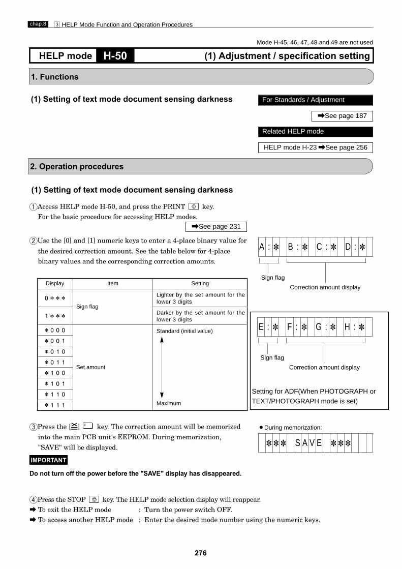
276
c HELP Mode Function and Operation Procedureschap.8
H-50 (1) Adjustment / specification settingHELP mode
1. Functions
(1) Setting of text mode document sensing darkness
2. Operation procedures
Display Item Setting
0***Sign flag
1***
*000
Set amount
Standard (initial value)
Maximum
*001
*010
*011
*100
*101
*110
*111
Lighter by the set amount for the lower 3 digits
Darker by the set amount for the lower 3 digits
(1) Setting of text mode document sensing darkness
qAccess HELP mode H-50, and press the PRINT key.For the basic procedure for accessing HELP modes.
wUse the [0] and [1] numeric keys to enter a 4-place binary value for
the desired correction amount. See the table below for 4-placebinary values and the corresponding correction amounts.
rPress the STOP key. The HELP mode selection display will reappear.a To exit the HELP mode : Turn the power switch OFF.a To access another HELP mode : Enter the desired mode number using the numeric keys.
ePress the [=] key. The correction amount will be memorized
"SAVE" will be displayed.
Do not turn off the power before the "SAVE" display has disappeared.
IMPORTANT
\See page 231
For Standards / Adjustment
\See page 187
Related HELP mode
HELP mode H-23 \See page 256
Correction amount display
Sign flag
A : 1 B : 1 C : 1 D : 1
¡During memorization:
1 1 1 S A V E 1 1 1
Mode H-45, 46, 47, 48 and 49 are not used
into the main PCB unit's EEPROM. During memorization,
Correction amount display
Sign flag
E : 1 F : 1 G : 1 H : 1
Setting for ADF(When PHOTOGRAPH or
TEXT/PHOTOGRAPH mode is set)
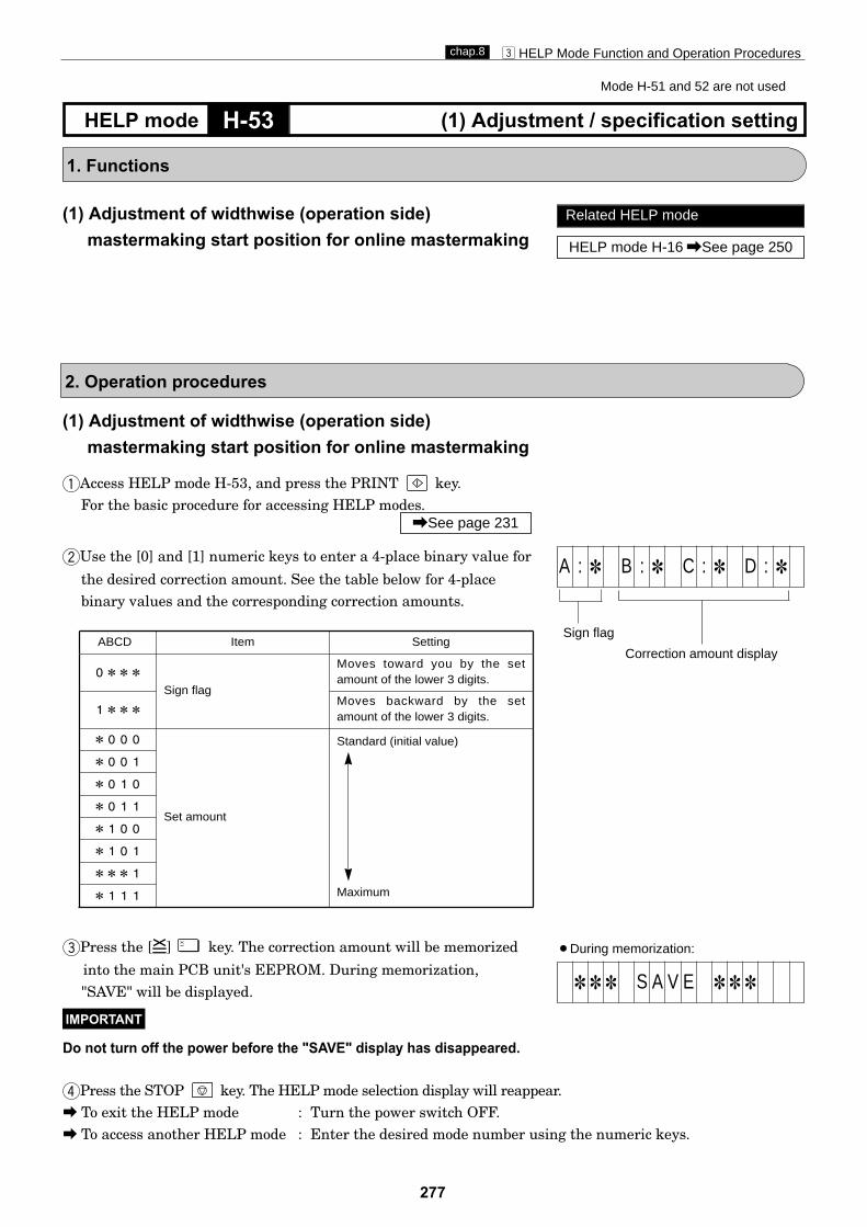
277
c HELP Mode Function and Operation Procedureschap.8
H-53 (1) Adjustment / specification settingHELP mode
1. Functions
(1) Adjustment of widthwise (operation side)mastermaking start position for online mastermaking
2. Operation procedures
ABCD Item Setting
0***Sign flag
Moves toward you by the setamount of the lower 3 digits.
1***Moves backward by the setamount of the lower 3 digits.
*000
Set amount
Standard (initial value)
Maximum
*001
*010
*011
*100
*101
***1
*111
(1) Adjustment of widthwise (operation side)mastermaking start position for online mastermaking
qAccess HELP mode H-53, and press the PRINT key.For the basic procedure for accessing HELP modes.
wUse the [0] and [1] numeric keys to enter a 4-place binary value for
the desired correction amount. See the table below for 4-placebinary values and the corresponding correction amounts.
rPress the STOP key. The HELP mode selection display will reappear.a To exit the HELP mode : Turn the power switch OFF.a To access another HELP mode : Enter the desired mode number using the numeric keys.
ePress the [=] key. The correction amount will be memorized
"SAVE" will be displayed.
Do not turn off the power before the "SAVE" display has disappeared.
IMPORTANT
\See page 231
Related HELP mode
HELP mode H-16 \See page 250
Correction amount display
Sign flag
A : 1 B : 1 C : 1 D : 1
¡During memorization:
1 1 1 S A V E 1 1 1into the main PCB unit's EEPROM. During memorization,
Mode H-51 and 52 are not used

278
c HELP Mode Function and Operation Procedureschap.8
H-55 (1) Adjustment / specification settingHELP mode
1. Functions
(1) Setting of ink check at printing start, cutting operationmode for master cutting, and interlocks
2. Operation procedures
ABCD Item Setting
0***
Enabled1***
Disabled
*0** 1 stroke = one-way motion
*1** 1 stroke = reciprocating motion
**0* Activated
**1* Deactivated
***0
***1
0110
Setting of ink check, that triggers ink replenishment if no ink is detected at printing start
Selection of cutter operation mode
Interlock: emergency stop if top cover or ejection box open
Not used
Initial value
(1) Setting of ink check at printing start, cutting operationmode for master cutting, and interlocks
qAccess HELP mode H-55, and press the PRINT key.For the basic procedure for accessing HELP modes.
wUse the [0] and [1] numeric keys to enter a 4-place binary value forthe desired correction amount. See the table below for 4-placebinary values and the corresponding correction amounts.
rPress the STOP key. The HELP mode selection display will reappear.a To exit the HELP mode : Turn the power switch OFF.a To access another HELP mode : Enter the desired mode number using the numeric keys.
ePress the [=] key. The correction amount will be memorizedinto the main PCB unit's EEPROM. During memorization,"SAVE" will be displayed.
Do not turn off the power before the "SAVE" display has disappeared.
IMPORTANT
\See page 231
Mode H-54 is not used.
Correction amount display
A : 1 B : 1 C : 1 D : 1
¡During memorization:
1 1 1 S A V E 1 1 1

279
c HELP Mode Function and Operation Procedureschap.8
H-56 (1) Adjustment / specification settingHELP mode
1. Functions
(1) Setting for selecting manipulation language
2. Operation procedures
ABCD Manipulation language
0000
0001
0010
0100
0011
0101
0110
Japanese
English
German
Italian
Spanish
French
(1) Setting for selecting manipulation languageqAccess HELP mode H-56, and press the PRINT key.
For the basic procedure for accessing HELP modes.
wUse the [0] and [1] numeric keys to enter a 4-place binary value forthe desired correction amount. See the table below for 4-placebinary values and the corresponding correction amounts.
rPress the STOP key. The HELP mode selection display will reappear.a To exit the HELP mode : Turn the power switch OFF.a To access another HELP mode : Enter the desired mode number using the numeric keys.
ePress the [=] key. The correction amount will be memorizedinto the main PCB unit's EEPROM. During memorization,"FONT UPDATE"and "SAVE" will be displayed.
Do not turn off the power before the "SAVE" display has disappeared.
IMPORTANT
\See page 231
Correction amount display
A : 1 B : 1 C : 1 D : 1
¡During memorization:
1 1 1 S A V E 1 1 1
Korean
Chinese Simplified1
Chinese Simplified2
Russian
Traditional Chinese
Thai Polish
0111
1000
10011010
1100
1011
1101
F O N T U P D A T E

280
c HELP Mode Function and Operation Procedureschap.8
H-59 (1) Adjustment / specification settingHELP mode
1. Functions
Display Item Setting
0 **Setting for end mark sensor 2
1 **
0 1 1 0 Factory setting
(1) Setting for end mark sensor 2
2. Operation procedures
(1) Setting for end mark sensor 2 .qAccess HELP mode H-59, and press the PRINTkey.
For the basic procedure for accessing HELP modes.
wUse the [0] and [1] numeric keys to enter a 4-place binary value forthe desired correction amount. See the table below for 4-placebinary values and the corresponding correction amounts.
rPress the STOP key. The HELP mode selection display willreappear.
a To exit the HELP mode : Turn the power switch OFF.a To access another HELP mode : Enter the desired mode number
using the numeric keys.
ePress the [=] key. The correction amount will be memorizedinto the main PCB unit's EEPROM. During memorization, "SAVE" will be displayed.
Do not turn off the power before the "SAVE" display has disappeared.
IMPORTANT
\See page 231
¡During memorization:
1 1 1 S A V E 1 1 1
Correction amount display
A : 1 B : 1 C : 1 D : 1
Mode H-57, H-58 are not used
*
* Enabled
Disabled
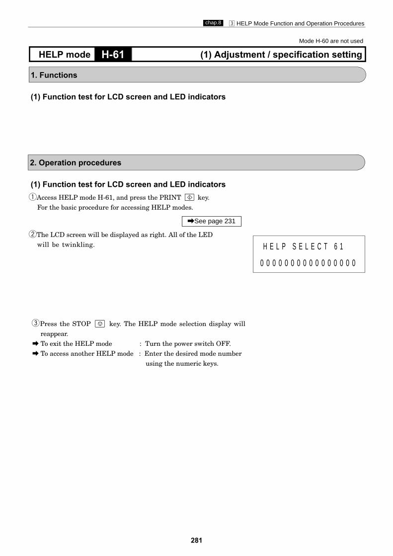
281
c HELP Mode Function and Operation Procedureschap.8
H-61 (1) Adjustment / specification settingHELP mode
1. Functions
(1) Function test for LCD screen and LED indicators
2. Operation procedures
(1) Function test for LCD screen and LED indicatorsqAccess HELP mode H-61, and press the PRINT key.
For the basic procedure for accessing HELP modes.
wThe LCD screen will be displayed as right. All of the LEDwill be twinkling.
Press the STOP key. The HELP mode selection display willreappear.
a To exit the HELP mode : Turn the power switch OFF.a To access another HELP mode : Enter the desired mode number
using the numeric keys.
e
\See page 231
0 0 0 0 0 0 0 0 0 0 0 0 0 0 0 0
Mode H-60 are not used
H E L P S E L E C T 6 1

282
c HELP Mode Function and Operation Procedureschap.8
H-63 (1) Adjustment / specification settingHELP mode
1. Functions
Display Item Setting
0 **Setting for A4 master cut
A4 size master cut
1 **
0 1 0 0 Factory setting
(1) Setting for A4 master cut
2. Operation procedures
(1) Setting for A4 master cut .qAccess HELP mode H-63, and press the PRINT key.
For the basic procedure for accessing HELP modes.
wUse the [0] and [1] numeric keys to enter a 4-place binary value forthe desired correction amount. See the table below for 4-placebinary values and the corresponding correction amounts.
rPress the STOP key. The HELP mode selection display willreappear.
a To exit the HELP mode : Turn the power switch OFF.a To access another HELP mode : Enter the desired mode number
using the numeric keys.
ePress the [=] key. The correction amount will be memorizedinto the main PCB unit's EEPROM. During memorization, "SAVE" will be displayed.
Do not turn off the power before the "SAVE" display has disappeared.
IMPORTANT
\See page 231
¡During memorization:
1 1 1 S A V E 1 1 1
Correction amount display
A : 1 B : 1 C : 1 D : 1
*
* B4/LG size master cut
Mode H-62 are not used
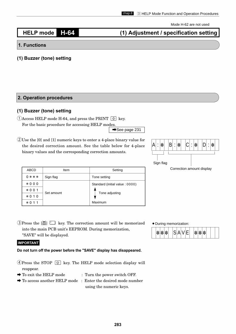
283
c HELP Mode Function and Operation Procedureschap.8
H-64 (1) Adjustment / specification settingHELP mode
1. Functions
ABCD Item Setting
0*** Sign flag Tone setting
Tone adjusting
*000
Set amount
Standard (initial value : 0000)
Maximum
*001
*010
*011
(1) Buzzer (tone) setting
2. Operation procedures
(1) Buzzer (tone) settingqAccess HELP mode H-64, and press the PRINT key.
For the basic procedure for accessing HELP modes.
wUse the [0] and [1] numeric keys to enter a 4-place binary value forthe desired correction amount. See the table below for 4-placebinary values and the corresponding correction amounts.
rPress the STOP key. The HELP mode selection display willreappear.
a To exit the HELP mode : Turn the power switch OFF.a To access another HELP mode : Enter the desired mode number
using the numeric keys.
ePress the [=] key. The correction amount will be memorizedinto the main PCB unit's EEPROM. During memorization, "SAVE" will be displayed.
Do not turn off the power before the "SAVE" display has disappeared.
IMPORTANT
\See page 231
¡During memorization:
1 1 1 S A V E 1 1 1
Mode H-62 are not used
Correction amount display
Sign flag
A : 1 B : 1 C : 1 D : 1

284
c HELP Mode Function and Operation Procedureschap.8
H-66 (1) Adjustment / specification settingHELP mode
1. Functions
ABCD Item Setting
0*** C mode master feed out B mode
1***
*0** OFF
*1** ON
*10*
*11*
***0
Not used
***1
0000 At shipment
Setting for master clamp opening/closing timing for master attachment
Setting of HELP 67/68 ON/OFF
master feed out C mode B mode
(1) Setting: clamp opening/closing timing of when amaster is attached; Help 67/68 ON/OFF.ON/OFF.
2. Operation procedures
(1) Setting: clamp opening/closing timing of when amaster is attached; Help 67/68 ON/OFF.
qAccess HELP mode H-66, and press the PRINT key.
For the basic procedure for accessing HELP modes.
wUse the [0] and [1] numeric keys to enter a 4-place binary value forthe desired correction amount. See the table below for 4-placebinary values and the corresponding correction amounts.
rPress the STOP key. The HELP mode selection display willreappear.
a To exit the HELP mode : Turn the power switch OFF.a To access another HELP mode : Enter the desired mode number
using the numeric keys.
ePress the [=] key. The correction amount will be memorized
"SAVE" will be displayed.
Do not turn off the power before the "SAVE" display has disappeared.
IMPORTANT
\See page 231
¡During memorization:
1 1 1 S A V E 1 1 1
Correction amount display
A : 1 B : 1 C : 1 D : 1
into the main PCB unit's EEPROM. During memorization,
Not used
Mode H-65 are not used

285
c HELP Mode Function and Operation Procedureschap.8
H-67 (1) Adjustment / specification settingHELP mode
1. Functions
(1) Setting of paper feed length.
2. Operation procedures
(1) Setting of paper feed length.qAccess HELP mode H-67, and press the PRINT key.
For the basic procedure for accessing HELP modes.
wUse the [0] and [1] numeric keys to enter a 4-place binary value forthe desired correction amount. See the table below for 4-placebinary values and the corresponding correction amounts.
rPress the STOP key. The HELP mode selection display willreappear.
a To exit the HELP mode : Turn the power switch OFF.a To access another HELP mode : Enter the desired mode number
using the numeric keys.
ePress the [=] key. The correction amount will be memorized
"SAVE" will be displayed.
Do not turn off the power before the "SAVE" display has disappeared.
IMPORTANT
\See page 231
¡During memorization:
1 1 1 S A V E 1 1 1
Correction amount display
Sign flag
A : 1 B : 1 C : 1 D : 1
into the main PCB unit's EEPROM. During memorization,
ABCD Item Setting
0000
0001
0010
Set amount
Min
Max
1101
1110
1111
0101 Initial value
0111
1000
1***
0***
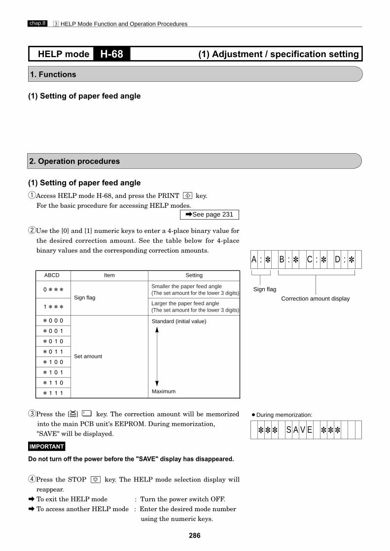
286
c HELP Mode Function and Operation Procedureschap.8
H-68 (1) Adjustment / specification settingHELP mode
1. Functions
ABCD Item Setting
0***Sign flag
1***
*000
Set amount
Standard (initial value)
Maximum
*001
*010
*011
*100
*101
*110
*111
Smaller the paper feed angle(The set amount for the lower 3 digits)
Larger the paper feed angle(The set amount for the lower 3 digits)
(1) Setting of paper feed angle
2. Operation procedures
(1) Setting of paper feed angleqAccess HELP mode H-68, and press the PRINT key.
For the basic procedure for accessing HELP modes.
wUse the [0] and [1] numeric keys to enter a 4-place binary value forthe desired correction amount. See the table below for 4-placebinary values and the corresponding correction amounts.
rPress the STOP key. The HELP mode selection display willreappear.
a To exit the HELP mode : Turn the power switch OFF.a To access another HELP mode : Enter the desired mode number
using the numeric keys.
ePress the [=] key. The correction amount will be memorized
"SAVE" will be displayed.
Do not turn off the power before the "SAVE" display has disappeared.
IMPORTANT
\See page 231
¡During memorization:
1 1 1 S A V E 1 1 1
Correction amount display
Sign flag
A : 1 B : 1 C : 1 D : 1
into the main PCB unit's EEPROM. During memorization,

287
c HELP Mode Function and Operation Procedureschap.8
H-69 (1) Adjustment / specification settingHELP mode
1. Functions
ABCD Item Setting
0000 B4 SIZE
A4 SIZE
0001 LEGAL SIZE
0011
Setting of model
(1) Setting of model
2. Operation procedures
(1) Setting of modelqAccess HELP mode H-69, and press the PRINT key.
For the basic procedure for accessing HELP modes.
wUse the [0] and [1] numeric keys to enter a 4-place binary value forthe desired correction amount. See the table below for 4-placebinary values and the corresponding correction amounts.
rPress the STOP key. The HELP mode selection display willreappear.
a To exit the HELP mode : Turn the power switch OFF.a To access another HELP mode : Enter the desired mode number
using the numeric keys.
ePress the [=] key. The correction amount will be memorized
"SAVE" will be displayed.
Do not turn off the power before the "SAVE" display has disappeared.
IMPORTANT
\See page 231
¡During memorization:
1 1 1 S A V E 1 1 1
Correction amount display
A : 1 B : 1 C : 1 D : 1
into the main PCB unit's EEPROM. During memorization,

288
c HELP Mode Function and Operation Procedureschap.8
H-72 (1) Adjustment / specification settingHELP mode
1. Functions
(1) Adjustment for mastermaking area lenghth.
2. Operation procedures
(1) Adjustment for mastermaking area lenghth.qAccess HELP mode H-72, and press the PRINT key.
For the basic procedure for accessing HELP modes.
wUse the [0] and [1] numeric keys to enter a 4-place binary value forthe desired correction amount. See the table below for 4-placebinary values and the corresponding correction amounts.
rPress the STOP key. The HELP mode selection display willreappear.
a To exit the HELP mode : Turn the power switch OFF.a To access another HELP mode : Enter the desired mode number
using the numeric keys.
ePress the [=] key. The correction amount will be memorized
"SAVE" will be displayed.
Do not turn off the power before the "SAVE" display has disappeared.
IMPORTANT
\See page 231
¡During memorization:
1 1 1 S A V E 1 1 1
Correction amount display
A : 1 B : 1 C : 1 D : 1
Mode H-70, H-71 are not used
into the main PCB unit's EEPROM. During memorization,
ABCD Item Setting
0***Sign flag
1***
*000
Set amount
Standard (initial value)
Maximum
*001
*010
*011
*100
*101
***1
*111
shorter amount of the lower 3 digits.
Mastermaking area lenghthlonger amount of the lower 3 digits.
Mastermaking area lenghth
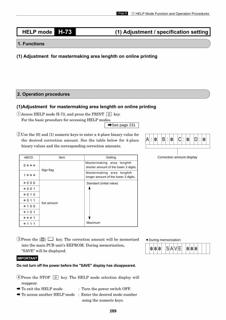
289
c HELP Mode Function and Operation Procedureschap.8
H-73 (1) Adjustment / specification settingHELP mode
1. Functions
(1) Adjustment for mastermaking area lenghth on online printing
2. Operation procedures
(1)Adjustment for mastermaking area lenghth on online printingqAccess HELP mode H-73, and press the PRINT key.
For the basic procedure for accessing HELP modes.
wUse the [0] and [1] numeric keys to enter a 4-place binary value forthe desired correction amount. See the table below for 4-placebinary values and the corresponding correction amounts.
rPress the STOP key. The HELP mode selection display willreappear.
a To exit the HELP mode : Turn the power switch OFF.a To access another HELP mode : Enter the desired mode number
using the numeric keys.
ePress the [=] key. The correction amount will be memorized
"SAVE" will be displayed.
Do not turn off the power before the "SAVE" display has disappeared.
IMPORTANT
\See page 231
¡During memorization:
1 1 1 S A V E 1 1 1
Correction amount display
A : 1 B : 1 C : 1 D : 1
into the main PCB unit's EEPROM. During memorization,
ABCD Item Setting
0***Sign flag
1***
*000
Set amount
Standard (initial value)
Maximum
*001
*010
*011
*100
*101
***1
*111
shorter amount of the lower 3 digits.
Mastermaking area lenghthlonger amount of the lower 3 digits.
Mastermaking area lenghth

290
c HELP Mode Function and Operation Procedureschap.8
H-74 (1) Adjustment / specification settingHELP mode
1. Functions
ABCD Item Setting
Disabled (initial value)
Enabled
3 ranks.(initial value)
5 ranks.
*0**
*1**
***0
***1
Setting of thermal head
(1) Setting of thermal head temperature Supplementing
2. Operation procedures
qAccess HELP mode H-74, and press the PRINT key.
For the basic procedure for accessing HELP modes.
wUse the [0] and [1] numeric keys to enter a 4-place binary value forthe desired correction amount. See the table below for 4-placebinary values and the corresponding correction amounts.
\See page 231
rPress the STOP key. The HELP mode selection display willreappear.
a To exit the HELP mode : Turn the power switch OFF.a To access another HELP mode : Enter the desired mode number
using the numeric keys.
¡During memorization:
1 1 1 S A V E 1 1 1
Correction amount display
A : 1 B : 1 C : 1 D : 1
ePress the [=] key. The correction amount will be memorized
in the main PCB unit's EEPROM. During memorization, "SAVE" will be displayed.
Do not turn off the power before the "SAVE" display has disappeared.IMPORTANT :
and master making darkness rank.
(1) Setting of thermal head temperature Supplementingand master making darkness rank.
temperature Supplementing
Setting of master making
darkness rank

291
c HELP Mode Function and Operation Procedureschap.8
H-76 (1) Adjustment / specification settingHELP mode
1. Functions
ABCD Item Setting
Normal (initial value)
Slightly lighter
Slightly darker
Much darker
00**
01**
10**
11**
Setting
(1) Document darkness correction for text/photographmode
2. Operation procedures
(1) Document darkness correction for text/photographmode
qAccess HELP mode H-76, and press the PRINT key.
For the basic procedure for accessing HELP modes.
wUse the [0] and [1] numeric keys to enter a 4-place binary value forthe desired correction amount. See the table below for 4-placebinary values and the corresponding correction amounts.
\See page 231
rPress the STOP key. The HELP mode selection display willreappear.
a To exit the HELP mode : Turn the power switch OFF.a To access another HELP mode : Enter the desired mode number
using the numeric keys.
¡During memorization:
1 1 1 S A V E 1 1 1
Correction amount display
A : 1 B : 1 C : 1 D : 1
ePress the [=] key. The correction amount will be memorized
in the main PCB unit's EEPROM. During memorization, "SAVE" will be displayed.
Do not turn off the power before the "SAVE" display has disappeared.IMPORTANT :
Mode H-74, H-75 are not used

292
c HELP Mode Function and Operation Procedureschap.8
H-80 (1) Adjustment / specification settingHELP mode
1. Functions
(1)
2. Operation procedures
qAccess HELP mode H-80, and press the PRINT key.For the basic procedure for accessing HELP modes.
wUse the [0] and [1] numeric keys to enter a 4-place binary value forthe desired correction amount. See the table below for 4-placebinary values and the corresponding correction amounts.
rPress the STOP key. The HELP mode selection display willreappear.
a To exit the HELP mode : Turn the power switch OFF.a To access another HELP mode : Enter the desired mode number
using the numeric keys.
ePress the [=] key. The correction amount will be memorized
"SAVE" will be displayed.
Do not turn off the power before the "SAVE" display has disappeared.
IMPORTANT
\See page 231
¡During memorization:
1 1 1 S A V E 1 1 1
Correction amount display
A : 1 B : 1 C : 1 D : 1
into the main PCB unit's EEPROM. During memorization,
Setting of ADF
Setting of INK save mode
(1)
ABCD Item Setting
0***
With optional ADF
1***
*0**
*1**
**0*
**1*
***0
***1
0101
Setting of ADF
Initial value
Without optional ADF
Setting of speed rank
Not used
Setting of Ink save modeOFF
ON
Mode H-77-79 are not used
3 print speed ranks
5 print speed ranks
Please adjust the drum speed by using H-38 when setting of print speed rank is changed.IMPORTANT
Setting of speed rank,ADF and Ink save mode.
Setting of print speed rank

293
c HELP Mode Function and Operation Procedureschap.8
1. Functions
(1) Display of ROM version¡ Displays version of the ADF PCB unit's ROM.
(1) Displaying ROM versionqAccess HELP mode H-83, and press the PRINT key.
For the basic procedure for accessing HELP modes.
Displays version of the ROM.
wPress the STOP key. The HELP mode selection display will
reappear.a To exit the HELP mode : Turn the power switch OFF.a To access another HELP mode : Enter the desired mode number
using the numeric keys.
\See page 231
2. Operation procedure
H-83 (ADF) (1) ROM version displaysHELP mode
ADF PCB unit
¡Displaying ROM version
V 1 . 1 1
Mode H-81 and H-82 are not used
ADF OP
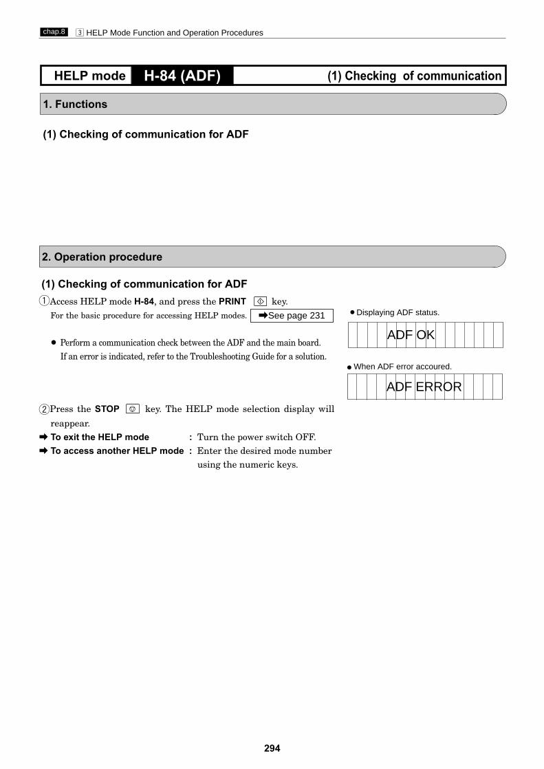
294
c HELP Mode Function and Operation Procedureschap.8
1. Functions
(1) Checking of communication for ADF
2. Operation procedure
H-84 (ADF) (1) Checking of communicationHELP mode
(1) Checking of communication for ADFqAccess HELP mode H-84, and press the PRINT key.
For the basic procedure for accessing HELP modes.
¡ Perform a communication check between the ADF and the main board. If an error is indicated, refer to the Troubleshooting Guide for a solution.
wPress the STOP key. The HELP mode selection display will
reappear.a To exit the HELP mode : Turn the power switch OFF.a To access another HELP mode : Enter the desired mode number
using the numeric keys.
\See page 231 ¡Displaying ADF status.
ADF OK
ADF ERROR
When ADF error accoured.¡
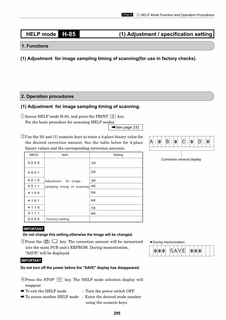
295
c HELP Mode Function and Operation Procedureschap.8
H-85 (1) Adjustment / specification settingHELP mode
1. Functions
(1) Adjustment for image sampling timing of scanning(for use in factory checks).
2. Operation procedures
qAccess HELP mode H-85, and press the PRINT key.For the basic procedure for accessing HELP modes.
wUse the [0] and [1] numeric keys to enter a 4-place binary value forthe desired correction amount. See the table below for 4-placebinary values and the corresponding correction amounts.
rPress the STOP key. The HELP mode selection display willreappear.
a To exit the HELP mode : Turn the power switch OFF.a To access another HELP mode : Enter the desired mode number
using the numeric keys.
ePress the [=] key. The correction amount will be memorized
"SAVE" will be displayed.
Do not turn off the power before the "SAVE" display has disappeared.
IMPORTANT
\See page 231
¡During memorization:
1 1 1 S A V E 1 1 1
Correction amount display
A : 1 B : 1 C : 1 D : 1
into the main PCB unit's EEPROM. During memorization,
ABCD Item Setting
0000
*001
*010
*011
*100
*101
*110
*111
0000 Factrory seeting
Adjustment for image
sampling timing of scanning
(1) Adjustment for image sampling timing of scanning.
1/8
2/8
3/8
4/8
5/8
7/8
8/8
6/8
Do not change this setting,otherwise the image will be changed.IMPORTANT

296
c HELP Mode Function and Operation Procedureschap.8
H-86 (1) Adjustment / specification settingHELP mode
1. Functions
(1) Setting of manual batch printing
2. Operation procedures
qAccess HELP mode H-86, and press the PRINT key.For the basic procedure for accessing HELP modes.
wUse the [0] and [1] numeric keys to enter a 4-place binary value forthe desired correction amount. See the table below for 4-placebinary values and the corresponding correction amounts.
rPress the STOP key. The HELP mode selection display willreappear.
a To exit the HELP mode : Turn the power switch OFF.a To access another HELP mode : Enter the desired mode number
using the numeric keys.
ePress the [=] key. The correction amount will be memorized
"SAVE" will be displayed.
Do not turn off the power before the "SAVE" display has disappeared.
IMPORTANT
\See page 231
¡During memorization:
1 1 1 S A V E 1 1 1
Correction amount display
A : 1 B : 1 C : 1 D : 1
Mode H-85 is not used
into the main PCB unit's EEPROM. During memorization,
(1) Setting of manual batch printing
ABCD Item Setting
0***
1***
*00*
*01*
*10*
*11*
***0
***1
0000 Initial value
Manual batch printing
mode ON/OFF setting
OFF
ON
Not used
Time between sets on
manual batch printing mode
1.5 sec.
3 sec.
5 sec.
10 sec.

297
c HELP Mode Function and Operation Procedureschap.8
H-89 (1) Adjustment / specification settingHELP mode
1. Functions
(1)
2. Operation procedures
q
Access HELP mode H-89, and press the PRINT key.For the basic procedure for accessing HELP modes.
w
Use the [0] and [1] numeric keys to enter a 4-place binary value forthe desired correction amount. See the table below for 4-placebinary values and the corresponding correction amounts.
\See page 231
Correction amount display
A : 1 B : 1 C : 1 D : 1
Setting of several special functions.
(1) Setting of several special functions of A-D.
ABCD Item Setting
0***
1***
*0**
*1**
**0*
**1*
***0
***1
0000 Initial value
Disabled.
Setting of special zoom
Mode H-87/88 are not used
2IN1 with scanner.
Setting of User ID function
Not used.
Enabled.
60%,130%
Disabled.
Enabled.
e
Press the [=] key. The correction amount will be memorized
"SAVE" will be displayed.
Do not turn off the power before the "SAVE" display has disappeared.IMPORTANT
¡During memorization:
1 1 1 S A V E 1 1 1into the main PCB unit's EEPROM. During memorization,
Use the DOCUMENT MODE SWITCH key to select theTEXT item.
r
Press the STOP key. The HELP mode selection display willreappear.
a To exit the HELP mode : Turn the power switch OFF.a To access another HELP mode : Enter the desired mode number
using the numeric keys.
t
Disabled.
Enabled.(Only for China)
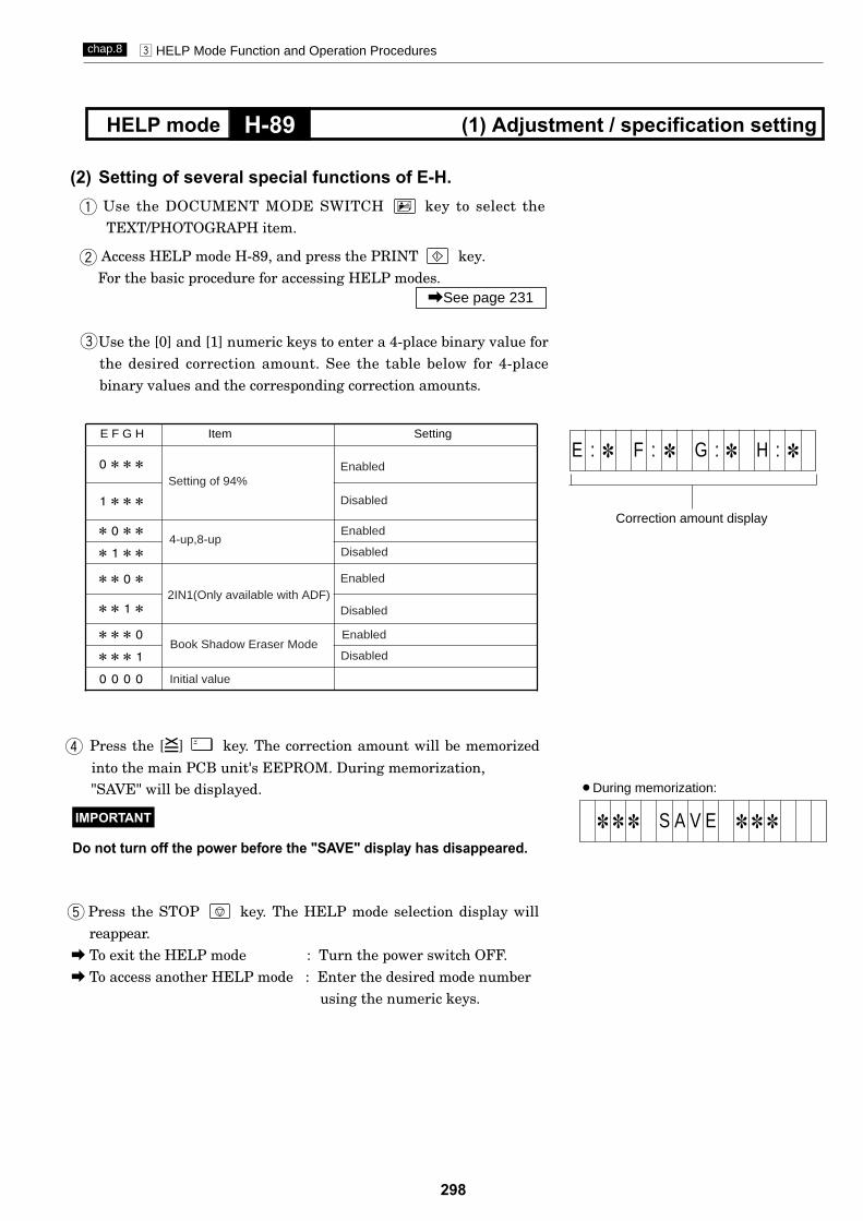
298
c HELP Mode Function and Operation Procedureschap.8
H-89 (1) Adjustment / specification settingHELP mode
¡During memorization:
1 1 1 S A V E 1 1 1
E F G H Item Setting
0***
1***
*0**
*1**
**0*
**1*
***0
***1
0000 Initial value
Setting of 94%Enabled
Disabled
Correction amount display
E : 1 F : 1 G : 1 H : 1
Press the [=] key. The correction amount will be memorized
"SAVE" will be displayed.
Do not turn off the power before the "SAVE" display has disappeared.
IMPORTANT
into the main PCB unit's EEPROM. During memorization, r
Use the DOCUMENT MODE SWITCH key to select theTEXT/PHOTOGRAPH item.
(2) Setting of several special functions of E-H.q
Access HELP mode H-89, and press the PRINT key.For the basic procedure for accessing HELP modes.
w
\See page 231
Use the [0] and [1] numeric keys to enter a 4-place binary value forthe desired correction amount. See the table below for 4-placebinary values and the corresponding correction amounts.
e
Press the STOP key. The HELP mode selection display willreappear.
a To exit the HELP mode : Turn the power switch OFF.a To access another HELP mode : Enter the desired mode number
using the numeric keys.
t
4-up,8-up
2IN1(Only available with ADF)
Book Shadow Eraser Mode
Enabled
Disabled
Enabled
Disabled
Enabled
Disabled

Press the STOP key. The HELP mode selection display willreappear.
a To exit the HELP mode : Turn the power switch OFF.a To access another HELP mode : Enter the desired mode number
using the numeric keys.
Press the [=] key. The correction amount will be memorized
"SAVE" will be displayed.
Do not turn off the power before the "SAVE" display has disappeared.
IMPORTANT
¡During memorization:
1 1 1 S A V E 1 1 1into the main PCB unit's EEPROM. During memorization,
0***
1***
*0**
*1**
**0*
**1*
***0
***1
0000 Initial value
Setting of master making
Enabled
Disabled
limit of 50
Setting of min.printing paper
Correction amount display
I : 1 J : 1 K : 1 L : 1
Use the DOCUMENT MODE SWITCH key to select thePHOTOGRAPH item.
(3) Setting of several special functions of I-L.
Access HELP mode H-89, and press the PRINT key.For the basic procedure for accessing HELP modes.
w
\See page 231
Use the [0] and [1] numeric keys to enter a 4-place binary value forthe desired correction amount. See the table below for 4-placebinary values and the corresponding correction amounts.
e
c HELP Mode Function and Operation Procedureschap.8
H-89 (1) Adjustment / specification settingHELP mode
q
r
t
299
I J K L Item Setting
Setting of special zoom
Disabled
Enabled
without printing.
Disabled
Enabled
Not used.
150%

c HELP Mode Function and Operation Procedureschap.8
H-90 (1) Adjustment / specification settingHELP mode
1. Functions
(1) Setting of Tape cluster
Mode H-87-89 are not used
300
2. Operation procedures
qAccess HELP mode H-90, and press the PRINT key.For the basic procedure for accessing HELP modes.
wUse the [0] and [1] numeric keys to enter a 4-place binary value forthe desired correction amount. See the table below for 4-placebinary values and the corresponding correction amounts.
rPress the STOP key. The HELP mode selection display willreappear.
a To exit the HELP mode : Turn the power switch OFF.a To access another HELP mode : Enter the desired mode number
using the numeric keys.
ePress the [=] key. The correction amount will be memorized
"SAVE" will be displayed.
Do not turn off the power before the "SAVE" display has disappeared.
IMPORTANT
\See page 231
¡During memorization:
1 1 1 S A V E 1 1 1
Correction amount display
A : 1 B : 1 C : 1 D : 1
into the main PCB unit's EEPROM. During memorization,
(1) Setting of Tape cluster
ABCD Item Setting
0***
Insert before printing,cut after printing
1***
*0**
*1**
**0*
**1*
***0
***1
0000 Initial value
Insert and cut after printing.
Setting of tape cluster
Setting of tape lenghth Divided by same tape lenghth
Divided by difference tape lenghth.
Enabled
Disabled
Setting of drum action
inserting
Setting of timing of tape
Stop waiting for tape inserting.
Do not stop.(only for TAP-14)
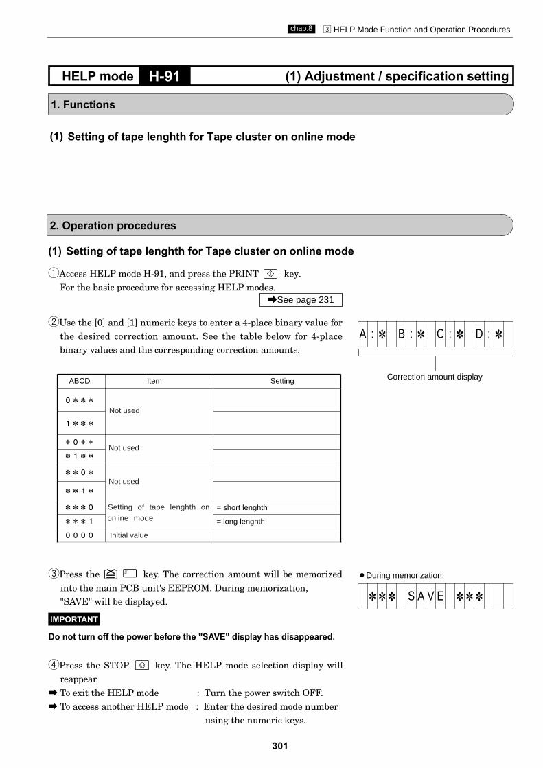
301
c HELP Mode Function and Operation Procedureschap.8
H-91 (1) Adjustment / specification settingHELP mode
1. Functions
(1)
2. Operation procedures
qAccess HELP mode H-91, and press the PRINT key.For the basic procedure for accessing HELP modes.
wUse the [0] and [1] numeric keys to enter a 4-place binary value forthe desired correction amount. See the table below for 4-placebinary values and the corresponding correction amounts.
rPress the STOP key. The HELP mode selection display willreappear.
a To exit the HELP mode : Turn the power switch OFF.a To access another HELP mode : Enter the desired mode number
using the numeric keys.
ePress the [=] key. The correction amount will be memorized
"SAVE" will be displayed.
Do not turn off the power before the "SAVE" display has disappeared.
IMPORTANT
\See page 231
¡During memorization:
1 1 1 S A V E 1 1 1
Correction amount display
A : 1 B : 1 C : 1 D : 1
into the main PCB unit's EEPROM. During memorization,
(1) Setting of tape lenghth for Tape cluster on online mode
ABCD Item Setting
0***
1***
*0**
*1**
**0*
**1*
***0
***1
0000 Initial value
Not used
Not used
Setting of tape lenghth on = short lenghth
= long lenghth
Setting of tape lenghth for Tape cluster on online mode
Not used
online mode

302
c HELP Mode Function and Operation Procedureschap.8
H-92 (1) Adjustment / specification settingHELP mode
1. Functions
(1)
2. Operation procedures
qAccess HELP mode H-92, and press the PRINT key.For the basic procedure for accessing HELP modes.
wUse the numeric keys to enter a 2-bit value from 23-50 forthe desired correction amount.
rPress the STOP key. The HELP mode selection display willreappear.
a To exit the HELP mode : Turn the power switch OFF.a To access another HELP mode : Enter the desired mode number
using the numeric keys.
ePress the [=] key. The correction amount will be memorized
"SAVE" will be displayed.
Do not turn off the power before the "SAVE" display has disappeared.
IMPORTANT
\See page 231
¡During memorization:
1 1 1 S A V E 1 1 1
Correction amount display
into the main PCB unit's EEPROM. During memorization,
Setting of tape length for Tape cluster
(1) Setting of tape length for Tape cluster
TAPE LENGTH1:28
Correction amount display
TAPE LENGTH2:28¡
aUse the DOCUMENT MODE SWITCH key to select the
TEXT item.
¡ TAPE LENGTH1(Setting for short tape length):aUse the DOCUMENT MODE SWITCH key to select the
TEXT/PHOTOGRAPH or PHOTOGRAPH item.
TAPE LENGTH2(Setting for long tape length):
Note: Unit is cm.

303
c HELP Mode Function and Operation Procedureschap.8
H-93 (1) Adjustment / specification settingHELP mode
1. Functions
(1)
2. Operation procedures
qAccess HELP mode H-93, and press the PRINT key.For the basic procedure for accessing HELP modes.
wUse the [0] and [1] numeric keys to enter a 4-place binary value forthe desired correction amount. See the table below for 4-placebinary values and the corresponding correction amounts.
rPress the STOP key. The HELP mode selection display willreappear.
a To exit the HELP mode : Turn the power switch OFF.a To access another HELP mode : Enter the desired mode number
using the numeric keys.
ePress the [=] key. The correction amount will be memorized
"SAVE" will be displayed.
Do not turn off the power before the "SAVE" display has disappeared.
IMPORTANT
\See page 231
¡During memorization:
1 1 1 S A V E 1 1 1into the main PCB unit's EEPROM. During memorization,
(1)
Adjustment of widthwise (operation side) scaning start position for 4-up and 8-up
Adjustment of widthwise (operation side) scaning start position for 4-up and 8-up
ABCD Item Setting
0***Sign flag
1***
*000
Set amount
Standard (initial value)
Maximum
*001
*010
*011
*100
*101
***1
*111
set amount of the lower 3 digits.
Moves backward by the set
Moves toward you by the
amount of the lower 3 digits.
Correction amount display
Sign flag
A : 1 B : 1 C : 1 D : 1
Correction amount display
Sign flag
E : 1 F : 1 G : 1 H : 1
Setting for ADF(When PHOTOGRAPH or
TEXT/PHOTOGRAPH mode is set)

304
c HELP Mode Function and Operation Procedureschap.8
H-94 (1) Adjustment / specification settingHELP mode
1. Functions
(1) UID ADMINISTRATOR password reset
2. Operation procedures
qAccess HELP mode H-94, and press the PRINT key.For the basic procedure for accessing HELP modes.
Press the STOP key. The HELP mode selection display willreappear.
a To exit the HELP mode : Turn the power switch OFF.a To access another HELP mode : Enter the desired mode number
using the numeric keys.
e
\See page 231
Correction amount display
C L E A R A D M I N P W
(1) UID ADMINISTRATOR password reset
wPress the [=] key and CLEAR keys keys simultaneously,
to execute resetting. The resetting will be memorized in themain PCB unit's EEPROM. After resetting ,the password of UID
C
ADMINISTRATOR will be reset to "000000".

305
c HELP Mode Function and Operation Procedureschap.8
H-97 (1) Adjustment / specification settingHELP mode
1. Functions
2. Operation procedures
qAccess HELP mode H-97, and press the PRINT key.For the basic procedure for accessing HELP modes.
Press the STOP key. The HELP mode selection display willreappear.
a To exit the HELP mode : Turn the power switch OFF.a To access another HELP mode : Enter the desired mode number
using the numeric keys.
e
\See page 231
Correction display
D P - M 4 * 0wThe machine model will be displayed as right.
Mode H-95/96 are not used
(1) The display for machine model.
The machine model is used on online mode.
(1) The display for machine model.

306
MEMO
307
Chapter 8 Others
z Electrical Parts Layout and Their Functions...........308(1) Switch / Clutches .................................................(2) Sensors..................................................................309(3) Lamps / Motors.....................................................310(4) PCB unit................................................................311(5) Connector VR/LED Layout and Functions..........312
x Overall Wiring Layout................................................314
Chapter 9
9
308

308
Electrical Parts Layout and Their Functionschap.9
Electrical Parts Layout and Their Functions(1) Switches/Clutches
3
1
7
8
6
10
2
9
5
4
snoitcnuF.oNmetI
Microswitch/switch
1
2
3
Opening and closing of the Scanner is detected.
4
Whether the drum is set or not is detected.
5
Opening and closing of the front cover is detected.
6
7
Whether the master ejection core is set or not and full or not is detected.
8Push switch
10
JOG switch (drum rotator switch)
Elevator lower limit switch
9 Master feeding clutch
Power switch
ClutchPaper feed clutch
Paper feed elevator descent switch
z
z

309
Electrical Parts Layout and Their Functionschap.9
(2) Sensors
181615
1712
36
97
811 10 4
14
5 1 2
Master is detected at the inlet of the master ejection box.Jam sensor photo-receiving Paper on the paper delivery side is detected.Jam sensor photo-emitting Detection of paper on paper ejection side.
snoitcnuF.oNmetI
Microsensor
Photointerrupter
1
2
3 Master clamp opening and closing lever A/C mode is detected.
Fixed document home position is detected.ADF home position is detected.
4 Master clamp opening and closing lever B mode is detected.
5 Drum home position and JAM detection position are detected.
6 Master attachment/detachment position is detected.
7 Main motor encoder sensor.
8 Press roller ON and OFF is detected.
9 Paper feed elevator top limit detection.
11 Center position of the print position adjustment is detected.
12 Weather the paper is placed or not is detected.
16
17
18
Master ejection sensor photo-emitting
Master ejection sensor photo-emittingPhoto-emitting of the master ejection and JAM detection sensor.
14
15
Master feed is detected.
Paper feed Length is detected.
10 Print position limit of the print position is detected.
13
13
z
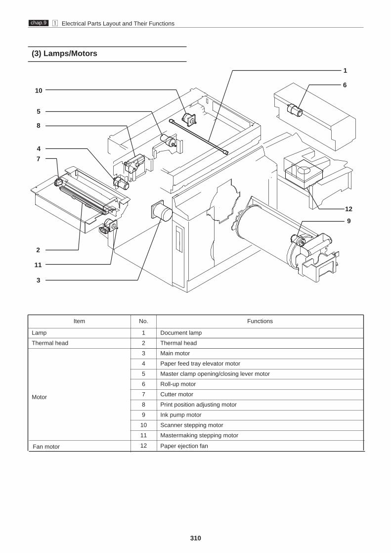
310
Electrical Parts Layout and Their Functionschap.9
snoitcnuF.oNmetI
pmal tnemucoD1pmaL
daeh lamrehT2daeh lamrehT
Motor
3 Main motor
4 Paper feed tray elevator motor
6 Roll-up motor
7 Cutter motor
8 Print position adjusting motor
9 Ink pump motor
Scanner stepping motor
Fan motor Paper ejection fan
11
10
Mastermaking stepping motor
5 Master clamp opening/closing lever motor
12
(3) Lamps/Motors
1
2
12
3
8
10
9
11
6
5
74
z

311
Electrical Parts Layout and Their Functionschap.9
snoitcnuF.oNmetI
.egami erutcip eht gnidaeR
1
tinu BCP DCC
2
Inverter PCB unit
3
Lamp lights up.
Control panel PCB unit
4
Control panel key, display.Ink detection PCB unit
5
Detecting Ink amount in the drum.
6End mark sensor PCB unit
7
Detection of master presence on master feed travel path, and end mark.
Main PCB unit Processing the image and controlling the machine on the whole.
.ylppus rewop CD htiw gniylppuSylppus rewop detalugeR
DP-24S
(4) PCB unit
1
3
2
6
7
5
4
z
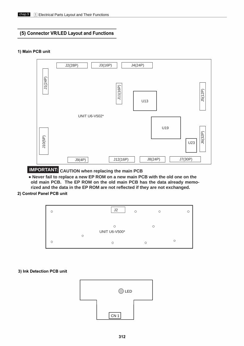
312
z Electrical Parts Layout and Their Functionschap.9
(5) Connector VR/LED Layout and Functions
2) Control Panel PCB unit
3) Ink Detection PCB unit
CN 1
LED
1) Main PCB unit
J10(
5P)
J6(3
2P)
J5(1
2P)J1
(24P
)
J11(
16P
)
J9(4P) J12(16P) J8(24P) J7(30P)
J2(28P) J3(16P) J4(24P)
U13
U19
U23
UNIT U6-V502*
J2
UNIT U6-V500*
CAUTION when replacing the main PCB ● Never fail to replace a new EP ROM on a new main PCB with the old one on the
old main PCB. The EP ROM on the old main PCB has the data already memo-rized and the data in the EP ROM are not reflected if they are not exchanged.
IMPORTANT:

313
z Electrical Parts Layout and Their Functionschap.9
7) CCD PCB unit
CCDCN
1
6) Inverter PCB unit
CN 2
CN
1
5) End Mark Sensor PCB unit
VR Function
VR1 Sensor sensitivity adjustment
4) Regulated power supply
UA043
CN
1
CN
51
F1(
FU
SE
)
CN
53
AC250V T5AH
IMPORTANT:● Do not to remove and replace the CCD PCB unit,otherwise,it is necessary to adjust in factory.

z Electorical Parts Layout and Their Functionschap.9
x Overall Wiring Layout
SC
AN
NE
R
CU
TT
ER
LIM
IT S
W(F
RO
NT
)
CU
TT
ER
LIM
IT S
W(R
EA
R)
MA
ST
ER
DE
TA
CH
ME
NT
/
AT
TA
CH
ME
NT
PO
SIT
ION
SE
NS
OR
EN
DM
AR
K S
EN
SO
R P
CB
UN
IT 2
EN
DM
AR
K S
EN
SO
R P
CB
UN
IT 1
EL
EV
AT
OR
DE
SC
EN
D S
W
314 315

U6-Y1100DUPLO DP-M400/M410/M420 U6-Y1100
Reproduction prohibited
Issued by : DUPLO CORPORATION