manual siemens mxl-iq
TRANSCRIPT
Cerberus Division
Version 1.0 Table of Contents
This CD-Rom contains
the information necessary to
install, operate and maintain
the Siemens, Cerberus Division
MXL/MXLV and MXL-IQ
Fire Protection Control Panels
Contents
Navigation
MXL/MXLV Control Panel
P/N 315-092036CD-8
MXL-IQ Control Panel
P/N 315-093624CD-9
Personalize/
Printout Cover
Personalize/
Printout Cover
There are three ways to navigate:1) Use the left hand index column (which appears as you proceed)2) Use the green buttons above to get to the corresponding manual3) Use the arrows in the menu bar above
There are 2 ways to enlarge or reduce:1) Use the magnifying glass in the menu bar above2) Use the three different page views in the menu bar.
www.PDF-Zoo.com

����������� ���
������������������������������� ��!"�#�$�%����&�'�#��$�'���'$(����%�)�$��*�+��
������������ ���
���������� ��������������������������
�������������� ���
�������������������������������,-�!��.'�-���'$����-$��-&��������/�����0�-'$����, ����+���
�������������
www.PDF-Zoo.com

�������
�������� ������������������������
�������������������������� ����������
�� ,%"+���"�����+���01*��2��������"��3"�3�"�(4�����+����%+��+����+�����5�+����%+���%�
,���+"��%��/����5�"�%33"�6�����+��������� �������� �������� �������
�� ��3%"%+��%���#�"����5�"����+�%+������6�����7��������+��+�"����%��%���+%+�������$�
����������+��8�5"���%����+��"�#�"�������+���01*��2��������"������#�"��+����(��
+���������3��%����#�+��9*� � ��"�5�"�+��+������+%��%+����%�����#�"�*���+��
:�"�������+"��+�����5�"�+���0�,��*�,������"������������ ��
�� ���9*;�,�;**�/;�*,�<$;���:�$,��5"���%�(�������+��"��%"+���"������
����+"��%��=�>������������+��������+���01*��2��������"��
� /�����+���������%=����"%���#�"��.�*?��������+���01*��2��������"��
�� ���#�"���������5�"�%�(��5�+���5����#�����%��"�����+�����+���=�������@
A�%��;*<����3
A�%�$�� ����+#�"&
A�%���;/���"���+������5�"�%���=���
A�%�/B0������"�/B0� ����+�%+������6�������3
����� ��������������������������������������������������������
��� ���������������� ���������������!!������!����������
"#$%%#&'$#()(*�
www.PDF-Zoo.com

��������������
��������� ������������������������������ � � �
�������� ��������������������������������������������������� � � �
������� ������������������������������������������������������ � � �
Minimum MXL-IQ Control Panel Configuration ________________________ 1 - 3
������ �� ��� ����� ������ ���������������������������������� � � �
SMB-2 Main Board _____________________________________________ 1 - 4
MPS-6 Power Supply ___________________________________________ 1 - 5
MPS-12 Power Supply __________________________________________ 1 - 5
MKB-4 Keyboard/Annunciator Panel _______________________________ 1 - 5
PIM-1 Peripheral Interface Module _________________________________ 1 - 6
PIM-2 Peripheral Interface Module _________________________________ 1 - 6
PAL-1 _______________________________________________________ 1 - 6
TSW-2 Tamper Switch __________________________________________ 1 - 6
BP-61 Batteries ________________________________________________ 1 - 7
BTX Batteries _________________________________________________ 1 - 7
������ ������ ����������������������������������������������� � �
MOM-2 Card Cage _____________________________________________ 1 - 8
MOM-4 Card Cage _____________________________________________ 1 - 8
CSM-4 Signal Module ___________________________________________ 1 - 8
CMI-300 Interface Module________________________________________ 1 - 9
CRM-4 Relay Module ___________________________________________ 1 - 9
CZM-4 Conventional Zone Module _________________________________ 1 - 9
ALD-2I Analog Loop Driver ______________________________________ 1 - 10
MOI-7 Voice and Annunciator Driver_______________________________ 1 - 10
MOD-16 Output Driver _________________________________________ 1 - 10
MID-16 Input Driver ____________________________________________ 1 - 11
NIM-1R Network Interface Module ________________________________ 1 - 11
�
������� �
www.PDF-Zoo.com

��!�� � �����
��
������"��#$��" ��%���� ��������������������������������������� � � �&
FP Intelligent Detector Series ____________________________________ 1 - 12
ICP Intelligent Control Point _____________________________________ 1 - 12
ICP-B6 Intelligent Control Point __________________________________ 1 - 12
ID Intelligent/Analog Detector Series ______________________________ 1 - 12
IL Intelligent/Analog Detector Series_______________________________ 1 - 13
LIM-1 Loop Isolator Module _____________________________________ 1 - 14
MSI Intelligent Manual Station Series ______________________________ 1 - 14
TRI Intelligent Interface Module Series _____________________________ 1 - 14
CZM-1B6 Remote Conventional Zone Module _______________________ 1 - 14
�%����� ��%���� ������������������������������������������� � � �'
DI Ionization Detector Series ____________________________________ 1 - 15
DT-11 Thermal Detector ________________________________________ 1 - 15
PE Photoelectric Detector Series _________________________________ 1 - 15
PBA-1191 Linear Beam Smoke Detector ___________________________ 1 - 15
��������� ������������������������������ & � �General Guidelines For Installing The MXL-IQ ________________________ 2 - 1
��������� ��������� (� ��� �)*��+ ���� ,��� ������������������ & � &
Install the MSE-3L Enclosure _____________________________________ 2 - 2
Install The TSW-2 Tamper Switch _________________________________ 2 - 2
Pull All Field Wiring Into The Backbox ______________________________ 2 - 3
Install the SMB-2 _______________________________________________ 2 - 3
Install the MPS-6/12 ____________________________________________ 2 - 3
Install the MKB-4 Keyboard/Annunciator ____________________________ 2 - 4
Install the PIM-1, PIM-2, and PAL-1 ________________________________ 2 - 5
Install the MOM-2 or MOM-4______________________________________ 2 - 6
Install the MOI-7, MOD-16, and MID-16 ____________________________ 2 - 9
Install Field Wiring_____________________________________________ 2 - 10
Check Field Wiring ____________________________________________ 2 - 10
������� &
www.PDF-Zoo.com

��!�� � �����
���
Start Up Procedure ____________________________________________ 2 - 10
System Function Checkout ______________________________________ 2 - 16
������� ������������������������������� - � �
�������� ��������������������������������������������������� - � �
Addresses ____________________________________________________ 3 - 1
System Modules _______________________________________________ 3 - 2
Remote System Modules ________________________________________ 3 - 2
.��" ��� �/��� /��!���#$������ ,��� � *��� ��� ������������ - � -
The Display ___________________________________________________ 3 - 3
Internal Audible Alarm ___________________________________________ 3 - 4
Modes Of Operation ____________________________________________ 3 - 5
$���� �������������������������������������������������������� - � 0
How The System Annunciates Fire Alarms __________________________ 3 - 6
Viewing the List of Alarms________________________________________ 3 - 7
How to Block Acknowledge A Fire Alarm ____________________________ 3 - 7
How to Individually Acknowledge A Fire Alarm ________________________ 3 - 7
Silencing The System ___________________________________________ 3 - 7
�����%������ �������������������������������������������������� - � 1
How The System Annunciates Supervisories _________________________ 3 - 8
Viewing the List of Supervisories __________________________________ 3 - 8
How to Block Acknowledge a Supervisory ___________________________ 3 - 8
How to Individually Acknowledge a Supervisory _______________________ 3 - 9
���!��� ������������������������������������������������������ - � 2
How The System Annunciates Troubles _____________________________ 3 - 9
Viewing The List of Troubles ______________________________________ 3 - 9
How to Block Acknowledge a Trouble______________________________ 3 - 10
How to Individually Acknowledge a Trouble _________________________ 3 - 10
������� -
www.PDF-Zoo.com

��!�� � �����
�%
�������� ��������������������������������������������������� - � �3
How The System Annunciates Security Conditions ___________________ 3 - 10
Viewing the List of Security Conditions _____________________________ 3 - 11
How to Individually Acknowledge a Security Condition_________________ 3 - 11
4���� ,�������� ���������������������������������������������� - � ��
Hard Reset __________________________________________________ 3 - 11
Soft Reset ___________________________________________________ 3 - 11
.��" ��� �/� /��!���#$������ ,��� � 5�!�� ��� ������������ - � �&
Limitations/Restrictions _________________________________________ 3 - 12
Global MKB Display Format _____________________________________ 3 - 12
Global Keypad Operation _______________________________________ 3 - 13
.��" ��� ��� ����������������������������������������������� - � ��
Operation of the Keys on the MXL-IQ Annunciator Panel ______________ 3 - 14
Numeric Keypad ______________________________________________ 3 - 14
The Command Keypad _________________________________________ 3 - 14
Overview of the Menu’s Structure _________________________________ 3 - 15
Beginning a Menu Session ______________________________________ 3 - 16
Introduction to the Acknowledge Menu _____________________________ 3 - 16
Introduction to the List Menu_____________________________________ 3 - 16
Introduction to the Control Menu __________________________________ 3 - 16
Introduction to the Test Menu ____________________________________ 3 - 16
Entering Your Password ________________________________________ 3 - 17
Entering a Module Number and Device Number _____________________ 3 - 17
Entering a Device Number with the Module Number __________________ 3 - 17
$�/6�7*8�58 ��� ������������������������������������������ - � �1
Entering the Acknowledge Menu _________________________________ 3 - 18
Acknowledge Alarm ___________________________________________ 3 - 18
Acknowledge Supervisory _______________________________________ 3 - 19
Acknowledge Trouble __________________________________________ 3 - 20
Acknowledge Security __________________________________________ 3 - 21
www.PDF-Zoo.com

��!�� � �����
%
*��� ��� ���������������������������������������������������� - � &&
Entering the List Menu _________________________________________ 3 - 22
List Status ___________________________________________________ 3 - 23
List Alarm ___________________________________________________ 3 - 23
List Supervisory_______________________________________________ 3 - 24
List Trouble __________________________________________________ 3 - 24
List Security Conditions_________________________________________ 3 - 25
List Sensitivity Settings _________________________________________ 3 - 26
List Voltages _________________________________________________ 3 - 26
List Temp ____________________________________________________ 3 - 28
List Module Type ______________________________________________ 3 - 28
List Device Type ______________________________________________ 3 - 29
List Message _________________________________________________ 3 - 29
List Software Version __________________________________________ 3 - 30
List Output States _____________________________________________ 3 - 31
List Device Usages ____________________________________________ 3 - 31
List Node Address _____________________________________________ 3 - 32
List ANALASER ______________________________________________ 3 - 32
List ANALASER – SMOKE_LEV __________________________________ 3 - 32
List ANALASER – FLOW_LEV ___________________________________ 3 - 33
List ANALASER – TRIP_PTS ____________________________________ 3 - 33
List Percent/ft ________________________________________________ 3 - 34
List Percent/ft – Senstvty _______________________________________ 3 - 35
List Percent/ft – Pre-alarm ______________________________________ 3 - 35
List Percent/ft – Analog _________________________________________ 3 - 35
List ASD_apps _______________________________________________ 3 - 35
��6�4�* ��� ����������������������������������������������� - � -0
Entering the Control Menu ______________________________________ 3 - 37
Control Reset ________________________________________________ 3 - 37
Control Sensitivity _____________________________________________ 3 - 37
Control Arm/dis _______________________________________________ 3 - 38
www.PDF-Zoo.com

��!�� � �����
%�
Control Output on/off___________________________________________ 3 - 38
Control Loop Arm _____________________________________________ 3 - 39
Control Loop Disarm ___________________________________________ 3 - 39
Control Net Link Request _______________________________________ 3 - 40
Control ANALASER ___________________________________________ 3 - 40
Control Percent/ft _____________________________________________ 3 - 41
Control Percent/ft - Senstvty _____________________________________ 3 - 41
Control Percent/ft - Pre-alarm ____________________________________ 3 - 41
Control Change Apps __________________________________________ 3 - 42
�8�� ��� ��������������������������������������������������� - � �&
Entering the Test Menu _________________________________________ 3 - 43
Test Set Time ________________________________________________ 3 - 43
Test Ground Fault _____________________________________________ 3 - 44
Test Power __________________________________________________ 3 - 44
Lamp Test ___________________________________________________ 3 - 45
Test Device LED ______________________________________________ 3 - 45
Test MOI Lamp Test ___________________________________________ 3 - 46
Test Network (X-Network, M-Network) _____________________________ 3 - 46
Test Override_________________________________________________ 3 - 46
Detector Cleaning _____________________________________________ 3 - 47
Event Log ___________________________________________________ 3 - 47
Test Pre-alarm________________________________________________ 3 - 47
Test ASD Devices _____________________________________________ 3 - 48
Test Summarize ______________________________________________ 3 - 48
Test Manual Activate ___________________________________________ 3 - 49
�����" �� ���!������" ����������������� � � �
������ ���� ���������������������������������������������������� � � �
Every Six Months ______________________________________________ 4 - 1
Every Year ____________________________________________________ 4 - 1
Fuse Replacement _____________________________________________ 4 - 1
Troubleshooting _______________________________________________ 4 - 2
������� �
www.PDF-Zoo.com
��!�� � �����
%��
7��9���� �������" ����������������������� ' � �
�������� ��������������������������������������������������� ' � �
System w/AUD ________________________________________________ 5 - 2
System SIL ___________________________________________________ 5 - 2
Loop w/AUD __________________________________________________ 5 - 2
Loop SIL _____________________________________________________ 5 - 2
Zone wAUD ___________________________________________________ 5 - 2
Zone SIL _____________________________________________________ 5 - 2
Cancel _______________________________________________________ 5 - 2
Extend _______________________________________________________ 5 - 2
��""����� 7��9���� ,������ ������������������������������������� ' � &
Walktest the System ____________________________________________ 5 - 3
Walktest Ending Sequence _______________________________________ 5 - 4
Walktest Entire ALD Loop, MOI-7 (MID-16), or CZM-4 Module ___________ 5 - 4
Walktest Ending Sequence _______________________________________ 5 - 5
Walktest Individual CZM-1B6 or CZM-4 Zone ________________________ 5 - 5
:����� *" ������������������������������ 0 � �CSG-M History Options__________________________________________ 6 - 1
*""�" ������ ����������������������������������������������� 0 � &
Enabling the History Option in CSG-M ______________________________ 6 - 4
From the MKB Menu ____________________________________________ 6 - 4
Local History Log Query _________________________________________ 6 - 5
Query Selection________________________________________________ 6 - 5
Query Filters __________________________________________________ 6 - 5
Navigating The History Display ____________________________________ 6 - 6
History Display Formats _________________________________________ 6 - 6
Device Event __________________________________________________ 6 - 6
Reset Event___________________________________________________ 6 - 6
Set Time Event ________________________________________________ 6 - 7
Block Acknowledge Event________________________________________ 6 - 7
������� '
������� 0
www.PDF-Zoo.com
��!�� � �����
%���
Audible Silenced Event __________________________________________ 6 - 8
Override Event ________________________________________________ 6 - 8
Audible Unsilenced Event ________________________________________ 6 - 8
Password Event _______________________________________________ 6 - 8
Configuration Changed Event _____________________________________ 6 - 9
Manual Sensitivity Set Event______________________________________ 6 - 9
Auto Sensitivity Set Event ________________________________________ 6 - 9
Logic Sensitivity Set Event ______________________________________ 6 - 10
History Print Formats At The MXL-IQ Panel _________________________ 6 - 10
MXL-IQ To CSG-M Download Formats_____________________________ 6 - 13
History Download Sequence _____________________________________ 6 - 14
������ �� 4���"� ������������������� � �
$*��&� �������������������������������������������������������� � �
����-33������������������������������������������������������� � -
�4��� �������������������������������������������������������� � '
����� �������������������������������������������������������� �
�;����0 ����������������������������������������������������� � �-
�;��� ������������������������������������������������������� � �
���� < �����0< �����0 ������������������������������������������ � �2
����& ������������������������������������������������������ � &'
����� ������������������������������������������������������ � &
6����4 ������������������������������������������������������ � &2
����� /�"�� ���� '�&1#'�&2 ������������������������������������ � --
����& ������������������������������������������������������� � -'
�������
www.PDF-Zoo.com
��!�� � �����
�=
������!�� ��%���� ��������������������������������������������� $ � �
��%��� $��" >���"�� ������������������������������������������ � � �
�)*��+ ������� ������������������������������������������������� � � �
�)*��+ ,��� ������ *�� ���������� ����������������������������� � � �
$���� >��������� ����������������������������������������������� 8 � �
8%����9 ����������������������������������������������������� ( � �
*�����"#6�*�����" ���!��� ������������������������������������ 5 � �
�������" $ �������� ,�� ���������������������������������������� : � �
$�������� �������� ������� ?$��@ ��������������������������������� � �
�)*��+ ���!�� �����"������������������������������������������� A � �
,��� *������ 7���" �������������������������������������������� / � �
6�� �� ���"� $���� ������������������������������������������� * � �
,��������< ���� �������� *"�� (�����< �� ,����� ,�� (��!������� (������� ������������������������������������������� � � �
�)*��+ ����� ,���� *��� ������������������������������������������ 6 � �
6�� (������� �� �)*��+ 4�%��� 0B3 �� :�"��� ���������������������� � � �
$�����=
www.PDF-Zoo.com

��!�� � �����
=www.PDF-Zoo.com

The �������������� ��� MXL-IQControl Panel is an advanced fire protectionand alarm control panel that provides superiorfire protection and multiplexed alarm reporting.
The MXL-IQ Control Panel can monitor upto 4 analog loops, each containing up to 60�������������� ��� intelligentdevices.
The MXL-IQ Control Panel can control awide variety of System outputs, such as:
• Conventional Form C relay contacts
• Solid State outputs
• Supervised outputs to control AlarmNotification Appliances
• Municipal Tie outputs
• Leased Line outputs
The MXL-IQ Control Panel can processlogical decisions based on the status ofinitiating devices. The System can respondwith customer-specified sequences ofoutput circuit operation.
The System continuously checks allsoftware and hardware for proper opera-tion. It continuously checks all Systemmemory components, control panel elec-tronic hardware, and the System program.A hardwire watchdog circuit is provided toensure that System programs are function-ing properly. If a problem develops with theprogram or processor, the watchdog circuitplaces the System into a trouble conditionand resets it.
To ensure reliable operation, the MXL-IQSystem is composed of independentmodules, each with its own microprocessor.If the main panel’s central processing unitstops, these modules, operating in default,still annunciate any alarm or troublethrough common lines called Any Alarmand Any Trouble. All of the modulescommunicate with the MXL-IQ Panelthrough a serial communications System.
All modules are continuously supervised fortheir presence and for proper operation.Problems are shown on the display to aid inservicing and troubleshooting (See Usingthe Menu in the OPERATIONS section).
The MXL-IQ System is designed so that firealarm operation has first priority over allother modes of operation. If the Systemloses battery and commercial power, itautomatically goes through an initializationroutine when power returns.
The MXL-IQ software was written in a high-level language for ease of maintenance.The software incorporates a multitaskingoperating system that allows the micropro-cessor to handle many tasks almostsimultaneously. This enables the MXL-IQSystem to handle communications to allinitiating and output option boards and tothe annunciator. This also enables theMXL-IQ System to check that everything isrunning.
���������
���������
������������
�����
���
www.PDF-Zoo.com

���
�����������
Figure 1The MXL-IQ Control Panel
ALARM
DISPLAY
NEXT HOLD
POWER
PARTIAL
SYSTEM
DISABLE
SECURITY
TROUBLE
SUPERVISORY
AUDIBLE
SILENCE
CERBERUS PYROTRONICS MXL-IQ
Interior View
Exterior View
www.PDF-Zoo.com

���
���������
�������������� ����������������������������������������������������������������������������������������������������� ���������������������������������!�����������������������"���������������#��������#�������$���������#����������������������!�������������������������������������$���#����������������"��!��������������������#��������������������������������������"�������#��������������������$������������������%����������$����������������%��$!����������������������##���������������������
�������������������������������$�������������������������������#����������������������������������������������������
#�������������&����������������������������������!����������������!�������������������������������%�����������������������
�������������� ��� �������� ��������� ��� ��������������� ���������������������� ��� ���� ���� �������!����"��������� ���� ��#��$%�&����"������$����$'����"��%%$ �%���'�������������������������#�!��������������������������()�&�*+���������������� ����,������������������������������� ����������������-�'.*/������()�&'+&��()�&�'0�����()�&�+..'�
���� ���� ������
� ������������������� ��� ���������������� �������� ������������ �!���!��"�����#��! � �#� ���� �
������������$��� ����%� �&�� �����������������!�� �'��(����)! �� �����%�� ��������� �!�����'�"�� �*!� � �#� �!&� (��� '�� �+ �!"��� �����������
,,, -�'������#�������� !��������!##�������������������� �(����
,,,, ���'�+.$�/��0/%�+.$�/�.�0/.%��� �+.$�/�1�0/1�����"�!�� �������! �'� �(�����
eludoM noitpircseD
ytitnauQmuminiMAPFN
27lacoL
27yrailixuA
27etomeRnoitatS
27yrateirporP
lartneC27)a(noitatS
LU)d,b(6701
,A211002ro,31
)c(2-BMS tinUniaMQI-LXM *1 1 *1 1 *1 1 1
21/6-SPM ylppuSrewoP 1 1 1 1 1 1 1
4-BKM lenaProtaicnunnA/draobyeK 1 1 1 1 1 1 1
2-MOM egaCdraCeludoMlanoitpO X 1 1 X X X 1
4-MOM egaCdraCeludoMlanoitpO X 1 1 X X X 1
4-MSC eludoMlangiS X 1 **2ro1 X X X )h(1
4-MZC eludoMenoZlanoitnevnoC *** *** *** *** *** X ***
I2-DLA revirDpooLgolanA *** *** *** *** *** **** ***
6B1-MZC eludoMenoZlanoitnevnoCetomeR *** *** *** *** *** X ***
----------- )f,e(seirettaB )e(1 )e(1 )e(1 )e(1 1 )d(1 )e(1
2-WST hctiwSrepmaT X X X X X )d(1 X
1-MIP eludoMecafretnIlarehpireP X X X 1 X 1 X
2-MIP eludoMecafretnIlarehpireP X X X 1 X 1 X
1-LAP retnirPgniggoL X X X 1 X 1 X
7-TEN ecafretnInoitacinummoC X X X X X X X
7-IOM revirDrotaicnunnAdnaecioV X X X X X X X
61-DOM revirDtuptuO X X X X X X X
61-DIM eludoMtupnI X X X X X X X
4-MRC eludoMyaleR X X X X X X X
003-IMC ecafretnILXC/LXM X X X X X X X
������� ������������� �������������������� ����� � ������ ������ �� ����23�$4�5� ����1��� ��%��������� �!�"�� � �����#���� ���$��%���&� '����()���$% ����������$$�#��*���+�(����������* �$�&�����%�� ����,������+�(
������$$����(��%��-������.��/ /�".0�#� 12�./!���3%������(�#���'�4��� �$����5� &����#�����2�.����� ����� '����� ������6�����������7�)��!.-�)'8�.-���#�)'8����'���)��!.�����$�#%���&��� ���������%�
!9-�.���:��� ������'���)'8�.��� �������������������.�9-��.��:��� ������'���)'8����� ������������������.�9-�����:��� �������& %����� ��*��;��#����#�����* �$�&�����%�� ����
�� ���������#�<�������)� ��*����&%�� ������ '����(=��//����� ��� �#�����12�./!������&� ������ ������ �� ���������$����������$�� !������,�����.��/ /"��0�����������$$����
������������� ������������������������������������ ���!���" �#������$���� ����%�����" ��&�������$�����������' �(���)�* ��&��������� �������+ ��&�������))�
www.PDF-Zoo.com

��-
�����������
������������%��.��/$���)����The basic MXL-IQ Control Panel consistsof the following components:
• SMB-2 Main Board
• MPS-6 or MPS-12 Power Supply
• MKB-4 Keyboard/Annunciator
• PAL-1 Logging Printer(NFPA Proprietary and UL 1076 configu-rations)
• PIM-1 Peripheral Interface Module(NFPA Proprietary and UL 1076 configu-rations)
• PIM-2 Peripheral Interface Module(NFPA Proprietary and UL 1076 configu-rations)
• MSE-3L Enclosure
• TSW-2 Tamper Switch(UL 1076 configuration only)
• BP-61, BTX-1, or BTX-2 Batteries
�/����$���/�$�*The SMB-2 Main Board contains:
• 16-bit central processing unit (CPU)
• System read-only memories (EPROMs)
• System random-access memory (RAM)
• FLASH memory for CSG-M
• Watchdog circuitry
• Network interface circuitry
• Battery charger
• 24V regulator
• AC transfer relay
• CZM-1B6 auxiliary power
• 24 VDC unregulated supply
• Two analog loops (initiating/control)
• Two notification appliance circuits(audible circuits)
• Two dry-contact relays (Form C)
Figure 2SMB-2 Main Board
CB1
NAC1
P14P1F2 BATTERY
20A
P2
BATTERY
MPS-6 MPS-12
F3 CZM-1B6 POWER
2 AMP
CB2
NAC2
10
11
12
CZM-1B6
POWER1
P8
TB3
P3
POWER TO MOM-4
2 AMP MAX.
3
4
4
1
2LOOP 2
NAC 2
NOT
USED
NAC 1
6
6
7
8
9
1
1
2
2
3
3
4
4
5
5
TO ANN-1P13
GND FAULT
DISCONNECT
TB2
LOOP 11
2
3
5
1
2
3
412A TO MOM-4
DO NOT USE
MNET
TRBLI
C
1
1
0
I
C
1
1
1
I
C
1
1
2
I
C
1
1
3
I
C
1
1
4
TB1
PROGRAMMER
P5
S7S4
P15
OFF ON
P17
1P10
D2300CP PRINTER
1P4
MOM-4
1
P6
1 1 1 1 1 ALR
F1
MPS-6
8 AMP
F4
MOM-4
15 AMP
SMB-2
www.PDF-Zoo.com
��0
�����������
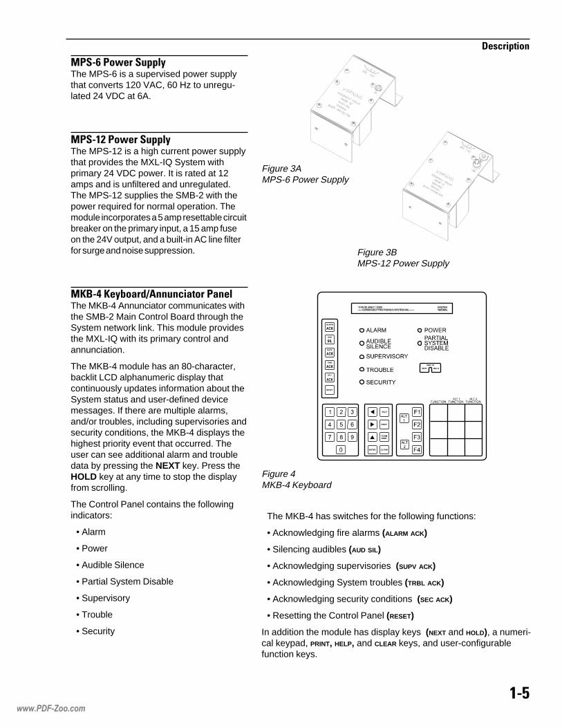
�#�,�#�1������")The MPS-6 is a supervised power supplythat converts 120 VAC, 60 Hz to unregu-lated 24 VDC at 6A.
�#����#�1������")The MPS-12 is a high current power supplythat provides the MXL-IQ System withprimary 24 VDC power. It is rated at 12amps and is unfiltered and unregulated.The MPS-12 supplies the SMB-2 with thepower required for normal operation. Themodule incorporates a 5 amp resettable circuitbreaker on the primary input, a 15 amp fuseon the 24V output, and a built-in AC line filterfor surge and noise suppression.
�2/�-�2�)3�$�*4�������$����#$��"The MKB-4 Annunciator communicates withthe SMB-2 Main Control Board through theSystem network link. This module providesthe MXL-IQ with its primary control andannunciation.
The MKB-4 module has an 80-character,backlit LCD alphanumeric display thatcontinuously updates information about theSystem status and user-defined devicemessages. If there are multiple alarms,and/or troubles, including supervisories andsecurity conditions, the MKB-4 displays thehighest priority event that occurred. Theuser can see additional alarm and troubledata by pressing the NEXT key. Press theHOLD key at any time to stop the displayfrom scrolling.
The Control Panel contains the followingindicators:
• Alarm
• Power
• Audible Silence
• Partial System Disable
• Supervisory
• Trouble
• Security
Figure 3AMPS-6 Power Supply
Figure 3BMPS-12 Power Supply
Figure 4MKB-4 Keyboard
The MKB-4 has switches for the following functions:
• Acknowledging fire alarms (ALARM ACK)
• Silencing audibles (AUD SIL)
• Acknowledging supervisories (SUPV ACK)
• Acknowledging System troubles (TRBL ACK)
• Acknowledging security conditions (SEC ACK)
• Resetting the Control Panel (RESET)
In addition the module has display keys (NEXT and HOLD), a numeri-cal keypad, PRINT, HELP, and CLEAR keys, and user-configurablefunction keys.
www.PDF-Zoo.com

��,
�����������
#�����#����.��$"������%$�����*�"�The PIM-1 module is an interface for anMXL-IQ System to remote peripheraldevices such as printers. It connects anRS-232C device to an MXL-IQ Systemwithout the peripheral device's protectiveground causing a ground fault. The inter-face operates at up to 9600 baud withoutlosing any characters.
#�����#����.��$"������%$�����*�"�The PIM-2 module is an interface thatallows the connection of UL listed EDPCentronics parallel printers to the MXL-IQSystem. It converts the RS-232C (serial)printer output to a Centronics parallelinterface. When used with the PAL-1, thePIM-2 provides a supervised parallel printer(NFPA 72 Proprietary or UL 1076) for theMXL-IQ System. However, this configura-tion is not supervised for data integrity.
#� ��The PAL-1 Logging Printer provides apaper record of the activity of the MXL-IQSystem.
������$�����1���.The TSW-2 Tamper Switch is a 3-positionswitch that monitors the opening of theMXL-IQ enclosure and reports a securityalarm. Closing the door automaticallyreturns the switch to its normal operatingposition. The switch can be pulled out toindicate a closed position for maintenancepurposes.
Figure 7TSW-2 Tamper Switch
Figure 6PAL-1 Parallel Printer
Figure 5PIM-1 Peripheral Interface Module
www.PDF-Zoo.com

��'
�����������
/#�,��/$�������The BP-61 is a module consisting of four 6V,15 AH batteries. The BP-61 is recommendedfor the NFPA 72 Local and Proprietary, andthe UL 1076 Systems. Actual battery sizedepends on System configuration. SeeAppendix C for battery calculations.
/���/$�������The BTX-1 batteries are a pair of 12V, 31AH batteries. The BTX-2 batteries are apair of 12V, 55 AH batteries. Actual batterysize depends on System configuration. SeeAppendix C for battery calculations.
Figure 8BP-61 Batteries
Figure 9BTX Batteries
�#����� ����
The following modules are available asoptions to the MXL-IQ Control Panel:
• MOM-2 Card Cage
• MOM-4 Card Cage
• CSM-4 Signal Module
• CMI-300 Interface Module
• CRM-4 Relay Module
• CZM-4 Conventional Zone Module* This module does not mount in the MSE-3L
enclosure.
• ALD-2I Analog Loop Driver
• MOI-7 Voice and Annunciator Driver*
• MOD-16 Output Driver*
• MID-16 Input Module*
• NIM-1R Network Interface Module
www.PDF-Zoo.com

��5
�����������
�������$�*��$&�The MOM-2 Card Cage contains 2 slots foroptional module cards; it can handle 2 half-width cards or 1 full-width card. The MOM-2provides 2 power-connector receptacles and2 data-connector receptacles. A 24 VDCcable that provides the main power used bythe optional modules, and an 8-wire ribboncable for connection of 5 VDC and data, areprovided with the MOM-2 installation kit.
����-��$�*��$&�The MOM-4 Card Cage contains 4 slots foroptional module cards; it can handle 4 half-width cards or 2 full-width cards. The MOM-4provides 2 power-connector receptaclesand 2 data-connector receptacles. A 24 VDCcable that provides the main power used bythe optional modules, and an 8-wire ribboncable for connection of 5 VDC and data, areprovided with the MOM-4 installation kit.
���-��&�$"���*�"�The CSM-4 Signal module controls 2supervised notification appliance circuits.Each circuit is capable of either Style Z(Class A) or Style Y (Class B) operation.Each circuit can be individually configuredfor notification appliances, municipal tie,leased line, or releasing service per NFPA12A, NFPA 13, and NFPA 2001.
Figure 10MOM-2 Card Cage
Figure 11MOM-4 Card Cage
S3
S1
S2
S4
G1
G2
Figure 12CSM-4 Signal Module
www.PDF-Zoo.com

��6
�����������
�����++������%$�����*�"�The CMI-300 provides modem communica-tions between an MXL-IQ System and a CXLSystem. The CMI-300 module is located onthe MOM-2/4 board in the MXL-IQ enclo-sure. The CMI-300 plugs into a half slot inthe MOM-2/4. It translates signals from theMXL-IQ communication lines of the SMB-2to CXL modem signals. This signal is thentransmitted along suitable cable to the CXM-1module in the CXL enclosure.
����-���"$)���*�"�The CRM-4 Relay module is an outputcontrol module that contains 4 relay out-puts. Form C contacts are rated at 2A, 30VDC/120 VAC resistive.
The CRM-4 has 4 LEDs. Two of the LEDsare user programmable.
�7��-����8������$"�7������*�"�The CZM-4 Conventional Zone moduleprovides four initiating device circuitscapable of Style D (Class A) or Style B(Class B) operation. Each zone has its ownaddress. You can use CSG-M to write acustom message for each zone(See CSGM Programming Manual,P/N 315-090381).
Figure 14CRM-4 Relay Module
Figure 15CZM-4 Conventional Zone Module
Figure 13CMI-300 Interface Module
www.PDF-Zoo.com
���+
�����������
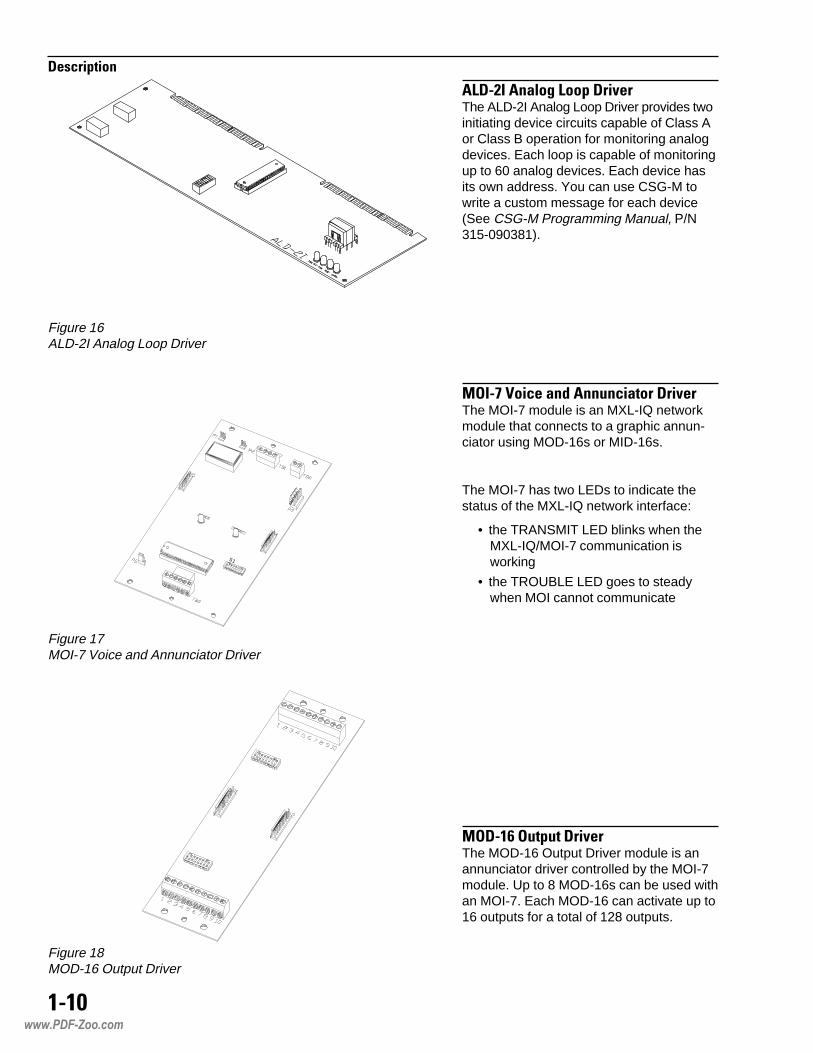
� �������$"�&� �������8��The ALD-2I Analog Loop Driver provides twoinitiating device circuits capable of Class Aor Class B operation for monitoring analogdevices. Each loop is capable of monitoringup to 60 analog devices. Each device hasits own address. You can use CSG-M towrite a custom message for each device(See CSG-M Programming Manual, P/N315-090381).
����'�9�����$�*��������$�������8��The MOI-7 module is an MXL-IQ networkmodule that connects to a graphic annun-ciator using MOD-16s or MID-16s.
The MOI-7 has two LEDs to indicate thestatus of the MXL-IQ network interface:
• the TRANSMIT LED blinks when theMXL-IQ/MOI-7 communication isworking
• the TROUBLE LED goes to steadywhen MOI cannot communicate
�����,�����������8��The MOD-16 Output Driver module is anannunciator driver controlled by the MOI-7module. Up to 8 MOD-16s can be used withan MOI-7. Each MOD-16 can activate up to16 outputs for a total of 128 outputs.
S1
Figure 17MOI-7 Voice and Annunciator Driver
Figure 18MOD-16 Output Driver
Figure 16ALD-2I Analog Loop Driver
www.PDF-Zoo.com

����
�����������
�����,����������8��The MID-16 module provides 16 generalpurpose inputs for user-defined operationsfor the MXL-IQ.
The MID-16 is controlled by the MOI-7module. Up to 8 MID-16s can be used withan MOI-7. The function of each individualinput is defined by the use assigned to it inCSG-M.
����������1��:������%$�����*�"�The NIM-1R provides a communication pathfor the following uses:
• as an MXL-IQ networking interface
• as a connection to Foreign Systems
• as a connection to AnaLASER detectors
When used as a networking interface theNIM-1R supports the connection of up to 63MXL-IQ Systems. This network also supportsa Network Command Center (NCC) thatmonitors all the MXL-IQs in the networkedgroup.
Output logic between MXL-IQ panels is madeusing CSG-M programming. CSG-M versions6.01 and higher include options for networkedMXL-IQ systems. Each MXL-IQ System isassigned a panel number. This panelnumber allows interactive programmingbetween panels using CSG-M.
The NIM-1R supports Style 4/7 connection.In the event of an NIM-1R communicationfailure, each MXL-IQ System continues tooperate as a stand-alone panel.
The NIM-1R can also be configured as anRS-232 or RS-485 two-wire interface toforeign systems. This operation is calledFSI (Foreign System Interface). The FSIresponds to a protocol and gathers informa-tion about the MXL-IQ status. The interfacesupports both single MXL-IQ Systems andnetworked systems. Typical use of thisinterface is between the MXL-IQ andbuilding management systems.
Figure 19MID-16 Input Driver
Figure 20NIM-1R Network Interface Module
www.PDF-Zoo.com

����
�����������
The intelligent/analog devices describedbelow are available for use with the MXL-IQControl Panel (SMB-2).
The UL identifiers for compatibility are thesame as the model names specified below.
#��������""�&���4��$"�&�#.����"��������������The FP-11 is an intelligent/analog photo-electric detector that can be used as anarea or duct detector [FP-11(d)]. It useseither a DB-11 low profile mounting base orDB-3S mounting base with the DB-ADPTadapter, a DB-X11RS mounting base withrelay or DB-X3RS mounting base with relaywith the DB-ADPT adapter, an ADBI-60audible base with the DB-ADPT adapter, oran AD-11P or AD-11XPR air duct housing.The FP-11 requires MXL-IQ Rev. 6.0 orhigher firmware.
#���������""�&�����.���$"���������The FPT-11 is an intelligent/analog rate-compensated/fixed-temperature typethermal and photoelectric detector. It canonly be used as an area detector. It useseither a DB-11 low profile mounting base orDB-3S mounting base with the DB-ADPTadapter, a DB-X11RS mounting base withrelay or DB-X3RS mounting base with relaywith the DB-ADPT adapter, or an ADBI-60audible base with the DB-ADPT adapter.The FPT-11 requires MXL-IQ Rev. 6.0 orhigher firmware.
��#�����""�&����������"�#����The ICP is an intelligent control point thatcan be used as an independent, remotelylocated notification appliance circuit (NAC).It communicates through the analog loop ofthe MXL-IQ System.
��#�/,�����""�&����������"�#����The ICP-B6 is an intelligent control pointthat can be used as an independent,remotely located notification appliancecircuit (NAC). It communicates through theanalog loop of the MXL-IQ System.
���,+#�����""�&���4��$"�&#.����"���������������The ID-60P is an intelligent/analog photoelec-tric detector that can be used as an area or
��� �; ��4��� �;�� 9��
duct detector [ID-6OP(d)]. It uses either aDB-3S low profile mounting base, a DB-X3RSmounting base with relay, an AD-3P ducthousing, or an ADBI-60 audible base.
���,+#������""�&���4��$"�&�#.�����"����������������1��.�<�$�������The ID-60PT is an intelligent/analog rate-compensated/fixed-temperature typethermal and photoelectric detector. It canonly be used as an area detector. It useseither a DB-3S low profile mounting base, aDB-X3RS mounting base with relay, or anADBI-60 audible base.
���,+������""�&���4��$"�&�����=$������������The ID-60I is an intelligent/analog ionizationdetector for use in open areas at altitudesof 0 to 4000 feet. It uses either a DB-3S lowprofile mounting base, a DB-X3RS mount-ing base with relay, or an ADBI-60 audiblebase.
���,+�<�����""�&���4��$"�&�����=$����<�&.��"����*����������The ID-60IH is an intelligent/analog ioniza-tion detector for use in open areas ataltitudes of 3000 to 8000 feet. It uses eithera DB-3S low profile mounting base, aDB-X3RS mounting base with relay, or anADBI-60 audible base.
���,+�������""�&���4��$"�&�����=$����<�&.�����9�"����)���������The ID-60IA is an intelligent/analog ioniza-tion high air-velocity detector for use inopen areas, computer facilities, and airducts at altitudes of 0 to 4000 feet. It useseither a DB-3S low profile mounting base, aDB-X3RS mounting base with relay, or anADBI-60 audible base.
���,+��<�����""�&���4��$"�&�����=$����<�&.�����9�"����)(�<�&.��"����*���������The ID-60IAH is an intelligent/analogionization high air-velocity, high altitudedetector for use in open areas, computerfacilities, and air ducts at altitudes of 3000 to8000 feet. It uses either a DB-3S low profilemounting base, a DB-X3RS mounting basewith relay, or an ADBI-60 audible base.
www.PDF-Zoo.com

����
�����������
���,+�/�����""�&���4��$"�&�����=$���������������������The ID-60IB is an intelligent/analog ioniza-tion detector for use in air duct applicationsat altitudes of 0 to 4000 feet. It uses eitherthe AD-3I housing or the AD-3XRI housing.
���,+�/<�����""�&���4��$"�&�����=$�������������<�&.��"����*����������The ID-60IBH is an intelligent/analogionization detector for use in air ductapplications at altitudes of 3000 to 8000feet. It uses either the AD-3I housing or theAD-3XRI housing.
� ��������""�&���4��$"�&�����=$������������The ILI-1 is an intelligent/analog ionizationdetector for use in open areas at altitudesof 0 to 4000 feet. It uses either a DB-3S lowprofile mounting base, a DB-X3RS mount-ing base with relay, or an ADBI-60 audiblebase.
� ���<�����""�&���4��$"�&�����=$����<�&.��"����*����������The ILI-1H is an intelligent/analog ionizationdetector for use in open areas at altitudesof 3000 to 8000 feet. It uses either a DB-3Slow profile mounting base, a DB-X3RSmounting base with relay, or an ADBI-60audible base.
� ���������""�&���4��$"�&�����=$����<�&.�����9�"����)���������The ILI-1A is an intelligent/analog ionizationhigh air-velocity detector for use in openareas, computer facilities, and air ducts ataltitudes of 0 to 4000 feet. It uses either aDB-3S low profile mounting base, aDB-X3RS mounting base with relay, or anADBI-60 audible base.
� ����<�����""�&���4��$"�&�����=$����<�&.�����9�"����)(�<�&.��"����*���������The ILI-1AH is an intelligent/analog ioniza-tion high air-velocity, high altitude detectorfor use in open areas, computer facilities,and air ducts at altitudes of 3000 to 8000feet. It uses either a DB-3S low profilemounting base, a DB-X3RS mounting basewith relay, or an ADBI-60 audible base.
� ���/�����""�&���4��$"�&�����=$����������������������The ILI-1B is an intelligent/analog ionizationdetector for use in air duct applications ataltitudes of 0 to 4000 feet. It uses either theAD-3I housing or the AD-3XRI housing.
� ���/<�����""�&���4��$"�&�����=$�������������<�&.��"����*����������The ILI-1BH is an intelligent/analog ioniza-tion detector for use in air duct applicationsat altitudes of 3000 to 8000 feet. It useseither the AD-3I housing or the AD-3XRIhousing.
� #�������""�&���4��$"�&�#.����"��������������The ILP-1 is an intelligent/analog photo-electric detector that can be used as anarea or duct detector [ILP-1(d)]. It uses eithera DB-3S low profile mounting base, aDB-X3RS mounting base with relay, anAD-3ILP or AD-3XRILP duct housing, or anADBI-60 audible base.
� #��������""�&���4��$"�&�#.����"���������������1��.�<�$�������The ILPT-1 is an intelligent/analog rate-compensated/fixed-temperature typethermal and photoelectric detector. It canonly be used as an area detector. It useseither a DB-3S low profile mounting base, aDB-X3RS mounting base with relay, or anADBI-60 audible base.
� #�������""�&���4��$"�&�#.����"��������������The ILP-2 is an intelligent/analog photo-electric detector that can be used as anarea or duct detector [ILP-2(d)]. It useseither a DB-3S low profile mounting base, aDB-X3RS mounting base with relay, anAD-3ILP or AD-3XRILP duct housing, or anADBI-60 audible base. The ILP-2 requiresMXL-IQ Rev. 3.0 or higher firmware.
� ��������""�&�����.���$"���������The ILT-1 is an intelligent rate-compen-sated/fixed-temperature type thermaldetector. It uses either a DB-3S low profilemounting base, a DB-X3RS mounting basewith relay, or an ADBI-60 audible base.
www.PDF-Zoo.com

���-
�����������
����� �������"$������*�"�The LIM-1 is a loop isolator module thatisolates short circuits on MXL-IQ analogloops. The LIM-1 operates in both Class Aand Class B circuits.
����+4�+�����""�&�����$��$"��$����The MSI-10/20 is an intelligent manualstation designed to interface with an analogloop. The MSI can be flush mounted orsurface mounted using the SB-5R mountingbox.
����+/4�+/�����""�&�����$��$"��$����The MSI-10B/20B is an intelligent manualstation designed to interface with an analogloop. The MSI-10B/20B can be flushmounted or surface mounted using theSB-5R mounting box.
���/,�����""�&�����$��$"��$����The MSI-B6F is an intelligent manual stationdesigned to interface with an analog loop.The MSI-B6F is a single-action station;when used with the MS-FD adapter, theMSI-B6F is a double-action station. TheMSI-B6F can be flush mounted or surfacemounted using the MS-FB backbox.
����/,�����""�&�����$��$"��$����The MSI-MB6 is an intelligent manualstation designed to interface with an analogloop. The MSI-MB6 is a single-actionstation; when used with the MS-DA plate,the MSI-MB6 is a double-action station.The MSI-MB6 can be flush mounted orsurface mounted using the MS-SBbackbox.
���������""�&�����$��$"��$����The MS-MI is an intelligent manual stationdesigned to interface with an analog loop.The MS-MI is a single-action station; whenused with the MS-DA plate, the MS-MI is adouble-action station. The MS-MI can beflush mounted or surface mounted usingthe MS-SB backbox.
����,+(�����,+�(�$�*�����,+������""�&��������%$�����*�"��The TRI-60 series modules are intelligentinterface modules that interface directshorting contact devices with the analogloops. The TRI-60 is a single-input module;the TRI-60R is a single-input module withan independently controllable Form C relay;the TRI-60D is a dual-input module.
����/,(�����/,�(�$�*�����/,�����""�&���������%$�����*�"��The TRI-B6 series modules are intelligentinterface modules that interface directshorting contact devices with the analogloops. The TRI-B6 is a single-input module;the TRI-B6R is a single-input module withan independently controllable Form C relay;the TRI-B6D is a dual-input module.
����/,���**����$3"�������%$�����*�"�The TRI-B6M addressable interface moduleinterfaces direct shorting contact deviceswith the analog loops. The TRI-B6M canmonitor a normally open or closed drycontact and it can report the status of thecontact
����(������(�$�*�����������""�&��������%$�����*�"��The TRI-S/R/D series modules are intelli-gent interface modules that interface directshorting contact devices with the analogloops. The TRI-S is a single-input module;the TRI-R is a single-input module with anindependently controllable Form C relay;the TRI-D is a dual-input module.
�7���/,�����������8������$"�7�����*�"�The CZM-1B6 Remote Conventional ZoneModule supports one zone of non-address-able initiating devices in either Style D(Class A) or Style B (Class B) configuration,for a maximum of 15 compatible 2-wiresmoke detectors and an unlimited numberof shorting devices.
www.PDF-Zoo.com
���0
�����������
The conventional devices described beloware available for use with the MXL-IQControl Panel.
The UL identifiers for compatibility are thesame as the model numbers.
���������=$�������������The DI-3 is an ionization detector for use inopen areas at altitudes of 0 to 4000 feet. Ituses the DB-3S low profile surface mount-ing base.
����<�����=$�����<�&.��"����*����������The DI-3H is an ionization detector for usein open areas at altitudes of 3000 to 8000feet. It uses the DB-3S low profile surfacemounting base.
����������=$�����<�&.�����9�"����)��������The DI-A3 is an ionization high air velocitydetector for use in open areas, computerfacilities, and air ducts at altitudes of 0 to4000 feet and at air velocities of 0 to 1200feet per minute. It uses the DB-3S lowprofile surface mounting base.
�����<�����=$�����<�&.�����9�"����)(<�&.��"����*����������The DI-A3H is an ionization high airvelocity, high altitude detector for use in airducts only at altitudes of 3000 to 8000 feetand at air velocities of 300 to 1200 feet perminute. It uses the DB-3S low profilesurface mounting base.
���/������=$����������������������The DI-B3 is an ionization detector for useonly in air ducts at altitudes of 0 to 4000feet. It must be used with a Series 3 airduct housing (AD-3I or AD-3RI).
���/�<�����=$��������������<�&.�"����*����������The DI-B3H is an ionization detector for useonly in air ducts at altitudes of 3000 to 8000feet. It must be used with a Series 3 airduct housing (AD-3I or AD-3RI).
���9 ������ � 9��
�������.���$"���������The DT-11 is a thermal detector for use inopen areas. It uses the DB-11 low profilesurface mounting base or the DB-3Smounting base with the DB-ADPT adapter.
# ���#.����"���������������The PE-3 is a photoelectric detector thatresponds to a wide range of both flamingand smoldering fire conditions. It useseither the DB-3S low profile surface mount-ing base or the AD-3ILP or AD-3XRILP airduct housing.
# ����#.����"����������������1��.�<�$������The PE-3T is a photoelectric detector withheat sensor that responds to a wide rangeof both flaming and smoldering fire condi-tions. It uses the DB-3S low profile surfacemounting base.
# ����#.����"���������������The PE-11 is a photoelectric detector thatresponds to a wide range of both flamingand smoldering fire conditions. It uses theDB-11 low profile surface mounting base,the DB-3S mounting base with theDB-ADPT adapter, or the AD-11P/11PRair duct housing.
# �����#.����"����������������1��.<�$�������The PE-11T is a photoelectric detector withheat sensor that responds to a wide rangeof both flaming and smoldering fire condi-tions. It uses the DB-11 low profile surfacemounting base or the DB-3S mounting basewith the DB-ADPT adapter.
#/����6�� ���$��/�$����:����������The PBA-1191 can detect light or darksmoke buildup at distances between thetransmitter (X) and receiver (R) of 17 feet to280 feet. The PBA-1191 can be used in avariety of areas, including large, narrow, orhigh rooms, and rooms with high airturbulence. The PBA-1191 requires thePBB-1191 base.
NOTE: Only one PBA-1191, and noadditional devices, can be connected to aCZM-4 initiating zone.
www.PDF-Zoo.com

���,
�����������
www.PDF-Zoo.com

����������������� ���������������������������������������������
This section provides general installationinstructions for mounting, wiring, andcheckout of the �������������� ����
MXL-IQ Control System.
Read this section before installing theequipment to ensure proper installation. Ifyou are not familiar with the MXL-IQ, alsoread the first section of the manual. Be sureto ask Siemens Building Technologies, Inc.Technical Support or an authorized Repre-sentative if you have any questions.
Install and use the MXL-IQ System inaccordance with the appropriate Local,NFPA, and NEC Code requirements.
��������
Refer to the last page of themanual for a Warning Noterequired by the FCC for all
commercial Class A computingequipment producing a clock
frequency of 10K Hz or greater.
������������������������������������ !"�#Always remove power (battery and AC)and wait at least 10 seconds to allow thesupply voltages to decay before installing orremoving any module, cable, or wiring.
NOTE: If available, use a printer duringthe installation procedure as adebugging tool.
Follow Steps 1 through 13 for installation.Each step is thoroughly explained in thefollowing pages.
1. Install the enclosure (page 2-2).
2. Install the TSW-2 Tamper Switchwhere required (page 2-2).
3. Pull the field wiring into the backboxand dress it to approximately where itwill go (page 2-3).
4. Install the SMB-2 (page 2-3).
5. Install the MPS-6 (page 2-3).
6. Install the MKB-4 (page 2-4).
7. Install the PIM-1, PIM-2, and PAL-1 (Ifapplicable) (page 2-5).
8. Install the MOM-2 or MOM-4 card(page 2-6).
9. Install the MOI-7, MOD-16, and MID-16(If applicable) (page 2-9).
10. Install Field Wiring (page 2-10).
11. Check Field Wiring (page 2-10).
12. Start-up Procedure (page 2-10).
13. System Function Checkout (page 2-16).
���������
�����������
�$��%&'���%$
(")www.PDF-Zoo.com

("(
�����������
��������������*+",!�+�-�����The MSE-3L is the enclosure for the MXL-IQ.
Consider the following when mounting thebackbox:
• Mounting height for visual and manualaccess to the MKB-4 Keyboard/annun-ciator
• Weight and size of enclosure
• Local Mounting codes
Fasten the backbox securely to a clean,dry, shock-free, and vibration-free surface.Position the backbox clear of obstructionsso that the door opens freely and so that
the indicators and controls are easilyaccessible.
NOTE: When the backbox is mountedsemi-flush using the MET-3L kit, be surethat the position of the backbox permits thedoor to swing fully open. (See MET-3LInstallation Instructions, P/N 315-095447.)
When deadfront construction is required,use the IQ-DFL panel (See IQ-DFL Installa-tion Instructions, P/N 315-095446.)
When the MSE-3L is used for remoteapplications, use the IQ-Blank where thereis no MKB-4 installed (See IQ-BlankInstallation Instructions, P/N 315-095482.)
�������������� ������.����������������()/a. Slip the door off the hinges of the box
and put it to one side temporarily.
b. Remove the knockouts in the backboxwhere field wiring is required (Refer toMSE-3L Power Limited WiringInstructions, P/N 315-095445, forlocation of knockouts).
c. Hold the empty enclosure against thewall at a height that provides easyaccess.
d. Mark drill points on the wall in the centerof the two slots on the upper rear of theMSE-3L.
e. Drill the two holes and screw in the topscrews, leaving a small gap between thewall and each top screw.
f. Mount the MSE-3L on the 2 bolts andthen install the bottom bolts.
g. Slip the door back on the hinges of theenclosure.
(��������������*0"(��������* ��-���������������������If your configuration (UL 1076) requires theTSW-2 Tamper Switch, install it now.
The TSW-2 mounts into the rectangularslot located in the lower right side of theMKB-4 panel.
1. Place the cable/connector and the switchterminals through the opening and pressfirmly into place.
2. Plug the cable on the TSW-2 into P9 onthe SMB-2 after installing the SMB-2.
Figure 21Mounting the MSE-3L Enclosure
Figure 22TSW-2 Tamper Switch
�$*��!!���%$�$*��'���%$*�%���1+�� !"�#�%$��%!�2�$+!
www.PDF-Zoo.com

(",
�����������
,��2��������������0���������������3�-4��5Pull all field wiring into the backbox anddress the wiring to the approximate locationto which it will go. Refer to the MSE-3LPower Limited Wiring Instructions, P/N 315-095445.
6�������������*�3"(��������������������Unpack the SMB-2. Inspect the module,looking for such things as integratedcircuits (ICs) not firmly seated in theirsockets, bent IC pins, connectors notproperly installed, dirt, packing material onthe board, etc.
The installation kit consists of the followingitems:
Two #6 nutsFour #6 screwsSix #6 washersSix #6 lockwashersTwo resistorsBattery cable with a wire
a. Place the SMB-2 over the two studs inthe upper right-hand portion of thebackbox (See Figure 23).
b. Secure in place using the hardwareprovided.
Be sure the screws and nuts are tight, asthey provide the earth ground connectionfor the SMB-2
7��������������2*"89)(���������������The MXL-IQ is designed to operate from a120 VAC, 60 Hz power source. Use aseparate or dedicated circuit-breaker. Wirein accordance with local codes and Article760 of the NEC, NFPA 70, latest edition.
Run the earth ground from a suitablesource to the MPS-6/12. Check localrequirements. Conduit is not an accept-able conductor.
Make sure that the dedicated circuit-breakerfor the MXL-IQ is turned off at the mains.
Place the mounting bracket for the MPS-6/12 over the two studs provided in theenclosure as shown in Figure 24.
Secure the MPS-6/12 to the MSE-3L byslipping the flat washers, then the
Figure 23Installing the SMB-2
Figure 24Installing the MPS-6
www.PDF-Zoo.com

("6
�����������
lockwashers, and finally the nuts over thetwo studs. Tighten them securely.
Connect the AC mains to MPS-6/12 asfollows:
Terminal
Black (hot) 1White (neutral) 2Green (earth ground) 3
Install the 14 gauge green ground strapspade lug side to Terminal 3 (green, earthground) of the MPS-6 or MPS-12. Securethe ring lug side of the ground strap to thenearest available stud in the enclosure. Thestud size may vary depending on the actualsystem modules and enclosure used.Because the stud may be either a #10thread of ¼" thread, nuts for both havebeen provided. The ground strap providedis long enough for all applications and thering lug is good for both #10 and ¼" studs.If possible, install the ring lug under one ofthe lockwashers and nuts which secure theMPS-6 or MPS-12 itself.
Connect the 3-wire cable coming from theMPS-6 to the SMB-2, P1, or connect the 8-wire cable coming from the MPS-12 to theSMB-2, P14.250
8��������������:3"6�:������9�����-�����
����������������� ���������������������������������������������
Figure 25Setting S1 on the ANN-1 Board
Unpack the MKB-4. Inspect the module forsuch things as integrated circuits (ICs) notfirmly seated in their sockets, bent IC pins,connectors not properly installed, dirt, andpacking material on the board.
NOTE: The MKB-4 is supplied with thekeyboard/annunciator mounted to thehinged panel.
�������������������� ����.*����������(7/a. Before installing the MKB-4 panel, set its
network address on S1, the switch onthe ANN-1 board located on the back ofthe MKB-4. Use dipswitches SW1 andSW2 on switch S1 to set the networkaddress of the MKB-4. Refer to Table 2for switch settings.
b. The MKB-4 module address is alwaysset within network addresses 248through 251.
c. One supervised MKB-4 must beinstalled at network address 251.Other supervised MKBs may be at theother addresses.
2ELBAT1-NNAEHTNOSGNITTESHCTIWS
HCTIWS
:ROFSGNITTESSSERDDA
842 942 052 152
1WS-1S-nepO
FFO-desolC
NO-nepO
FFO-desolC
NO
2WS-1S-nepO
FFO-nepO
FFO-desolC
NO-desolC
NO
3WS-1S-desolC
NO-desolC
NO-desolC
NO-desolC
NO
4WS-1S-desolC
NO-desolC
NO-desolC
NO-desolC
NO
5WS-1S noisivrepuSgnitteSeeS noisivrepuSgnitteSeeS noisivrepuSgnitteSeeS noisivrepuSgnitteSeeS noisivrepuSgnitteSeeS
:ETON :ETON :ETON :ETON :ETON .esuerutufrofera4WS-1Sdna3WS-1SsehctiwS.noisivretpustcelesotdesusi5WS-1ShctiwS
����������!��"������Use switch S1-SW5 on the ANN-1 to selector deselect supervision. If your ANN-1 hasa switch with position 1 indicated on theleft-hand side, ignore the printing on theswitch. SW1 on S1 is at the extreme right-hand side of S1, regardless of any othermarking.
www.PDF-Zoo.com

("7
�����������
NOTE: When you select non-supervisionfor an annunciator, there must also be oneand only one supervised annunciator atthe same address. The supervisory modeis independent of the network address.
�������������!��"����� S1-SW5 = Closed (ON)
��������������#��!��"����� S1-SW5 = Open (OFF)
$�����������$%&#�.����������������(8/
1. Install three screws in the first group ofthree tapped holes in the right flange.Leave a 1/8-inch gap between the headof the screw and the flange. Slide theslots of the MKB-4 panel hinge under thehead of the screws and tighten.
2. After the MKB-4 is mounted to theenclosure, connect the cable (P/N 555-192238) between P1 on the ANN-1 (onthe back of the MKB-4) and P8 on theSMB-2.
�������
Be sure the black tracer wire on the edge ofthe cable is close to the 1 on position 1 ofconnector P1 on the ANN-1 and the 1 onposition 1 of P8 on the SMB-2.
;��������������2��")��2��"(������2�!")
'($#)1. Install the PIM-1 on the back of the
MKB-4 panel as shown in Figure 27.Position the PIM-1 so the TB1 is on theleft side of the board.
2. Mount the PIM-1 module on the raisedstuds with the hardware provided.
3. Using the cable supplied with the PIM-1,connect PIM-1, P-1 to ANN-1, P1 (SeeFigure 27).
4. Using the cable supplied with the MKB-4,connect PIM-1, P2 to SMB-2, P8 (SeeFigure 27).
Figure 26Installing the MKB-4 Keyboard/Annunciator
MSE-3L
Back of MKB-4
P2P1
TB1
P1
1
ANN-1
PIM-1
To P8 on the SMB-2(Cable supplied with MKB-4)
Cable supplied
with PIM-1
(P/N 555-192242)
Figure 27Installing a PIM-1 on the Back of an MKB-4
www.PDF-Zoo.com

("8
�����������
Figure 28UPS Wiring Diagram
������
��� ������������� ��������������������
��� �������������������������� ������!������ ����������������������"�������
�#� $����$�%��&%�'�(�������� )#���*+�
��� %����!,������-������.�������&������(�����������
�*� %����!,������-������.�������&����*��(�����������
'($#�*'�+#)The PIM-2 and printer require a standbypower source in the event of a loss ofprimary input power (AC mains). Refer toFigure 28 for the connection of a UPS tomeet this requirement.
1. Before installing a PIM-2 in the MXL-IQsystem, a PIM-1 must be alreadyinstalled.
2. Wiring from the PIM-1 to the PIM-2 mustbe within 25 feet in rigid conduit (Refer toTable 3).
������������� �������������������
������������ ���!!"�#
������������ ��������
����������
���������� �� ��
�����������
��������������������� ��
�!"!���!#$�% &'(�#)�
3. Figure 29 shows the proper installationof the PIM-2 with the MXL-IQ system.
4. Programming the CSG-M is requiredwhen using a PIM-2 and parallel printer.Configure one of the following fourprinter types on the MKB-4:
Supervised PIM-2 80 column color
Supervised PIM-2 132 column color
Supervised PIM-2 80 column
Supervised PIM-2 132 column (forPAL-1 and NFPA 72 Proprietary)
5. Set the dipswitches on the back of thePIM-2 to agree with the communicationsparameters configured in the CSG-M.Refer to Table 4 for the dipswitchdefinitions.
<��������������%�"(�����%�"6
If a system requires the MOM-2 or MOM-4optional card cage (Figures 10 and 11,page 20), now is the time to install it.Unpack the card cage and its attachedbackplate and inspect it, looking for suchthings as connectors not properlyinstalled, dirt, and packing material on theboard.
The MOM-2/4 installation kits include thefollowing items
��� $��
)�"���*� )�"���*�
)$#+),%�,-.��*� )$#+),%�,-.��*�
)$#+),%/0�-��*� )$#+),%/0�-��*�
)%#$0)1�2��1*� #-3,0��33�$$��0"4��0�(�
)%#$0)1�2����1* )#-3,0#$�%�
#-3,0��33�$$��0"4��0�(� )#4�"54$,0�
)#-3,0#$�%�
)#4�"54$,0
www.PDF-Zoo.com

(";
�����������
Figure 29PIM-2 to MXL-IQ Wiring Diagram
PIM-2 (REAR VIEW)
OUTPUT SW1
(REFER TO TABLE 4)
PWRINPUT
PARALLEL PRINTER (REAR VIEW)
CENTRONICS PARALLEL
ANN-1
MKB-4
PIM-1SEE INSTL. INSTR.
P/N 315-091462
TB1
CABLE SUPPLIED WITH PIM-2(SEE NOTE 2)SUPERVISED
(REFER TO NOTES 9 AND 10)THE CONNECTION IS NOT SUPERVISED FOR DATA INTEGRITY BETWEEN PIM-2 AND THE PRINTER.
CABLE NOT SUPPLIED(SEE NOTE 1)SUPERVISED
PIM-2 POWER CABLEMUST BE IN CONDUIT
INSTALL IN UL LISTED GANGBOX
PIM-2 POWER TRANSFORMERSUPPLIED WITH PIM-2 (SEE NOTE 3)
120 VAC60 Hz
XFMR
NOTES: 1. Maximum cable
distance from PIM-1 toPIM-2 cable is 25 feet.The two modules mustbe in the same room.
2. The maximum distancefrom the PIM-2 to theparallel printer is 6 feet.The two modules mustbe in the same room.
3. PIM-2 power (PWR) isconnected to the 5VDC, 600mA trans-former supplied with thePIM-2. The transformerrequires 120 VAC, 60Hz, 0.5A max.
4. For NFPA 72 Local,Auxiliary, and RemoteStation configurations,connect the output ofthe PIM-2 to any ULlisted EDP Centronicsparallel printer.
5. The parallel printer mustsupport the EPSON FXcommand set.
6. The PIM-2 input andoutput connectors areDB-25 female.
7. Pressing RESET on thePIM-2 causes the unitto read the SW1settings. The statusLED is lit when the unitis powered. Do not usethe COPY button.
8. For NFPA Proprietaryand UL 1076configurations, useparallel printer ModelPAL-1, a UL listed forfire Centronics parallelprinter.
9. The parallel printer issupervised for AC, on/off line, paper out, paperjam, and connection tothe PIM-2.
10. The PIM-2 issupervised for power,connection to theprinter, and connectionto the PIM-1.
11. After loading paper inthe PAL-1 printer, turnoff the power and followthe steps below:• While pressing the
LOAD PARK button,turn on the power tothe PAL-1 printer.Continue pressingthe LOAD PARKbutton for 5 seconds.
• Release the LOADPARK button.
• The current settingwill print.
• When printing iscompleted, the ONLINE indicator will belit. If the ON LINEindicator is not lit,press the ON LINEbutton.
$������������������������������������
���.�$,#$�,4#�,0�6���&�������)��+0��%)���
� � � � 1 � (
7�'���'���18��(����������
99 � 99 � �
� � 99 99 �
99 99 � � �
���'�'�(�
99 �
���'��#:744
99 �
���'�#-3,)��#-3,�7
99 �
6 ��� �& 69#$,%4$,;#$,%�.��
99 �
7����� � 99
/012.����������%���"��%��
0334$�40�2/
0/450�/4&'0%25
www.PDF-Zoo.com
("<
�����������
MOM-2
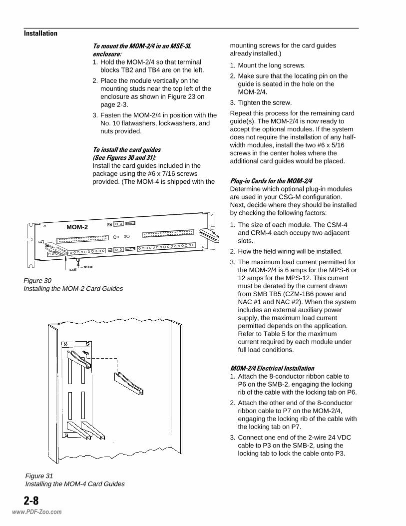
Figure 30Installing the MOM-2 Card Guides
mounting screws for the card guidesalready installed.)
1. Mount the long screws.
2. Make sure that the locating pin on theguide is seated in the hole on theMOM-2/4.
3. Tighten the screw.
Repeat this process for the remaining cardguide(s). The MOM-2/4 is now ready toaccept the optional modules. If the systemdoes not require the installation of any half-width modules, install the two #6 x 5/16screws in the center holes where theadditional card guides would be placed.
'��#���,�� ���������$-$#�*�Determine which optional plug-in modulesare used in your CSG-M configuration.Next, decide where they should be installedby checking the following factors:
1. The size of each module. The CSM-4and CRM-4 each occupy two adjacentslots.
2. How the field wiring will be installed.
3. The maximum load current permitted forthe MOM-2/4 is 6 amps for the MPS-6 or12 amps for the MPS-12. This currentmust be derated by the current drawnfrom SMB TB5 (CZM-1B6 power andNAC #1 and NAC #2). When the systemincludes an external auxiliary powersupply, the maximum load currentpermitted depends on the application.Refer to Table 5 for the maximumcurrent required by each module underfull load conditions.
$-$#�*��.� ��� ��(���������1. Attach the 8-conductor ribbon cable to
P6 on the SMB-2, engaging the lockingrib of the cable with the locking tab on P6.
2. Attach the other end of the 8-conductorribbon cable to P7 on the MOM-2/4,engaging the locking rib of the cable withthe locking tab on P7.
3. Connect one end of the 2-wire 24 VDCcable to P3 on the SMB-2, using thelocking tab to lock the cable onto P3.
���/��������$-$#�*��������$�.#�+�� ������1. Hold the MOM-2/4 so that terminal
blocks TB2 and TB4 are on the left.
2. Place the module vertically on themounting studs near the top left of theenclosure as shown in Figure 23 onpage 2-3.
3. Fasten the MOM-2/4 in position with theNo. 10 flatwashers, lockwashers, andnuts provided.
������������ �� ���� ����������������0��� ��)��Install the card guides included in thepackage using the #6 x 7/16 screwsprovided. (The MOM-4 is shipped with the
Figure 31Installing the MOM-4 Card Guides
www.PDF-Zoo.com

("=
�����������
3. If a connection to a MOD-16 module onanother rail is required, use the optionalcable P/N 555-190941.
$(1#)2�������������)34�!����)#))�
1. Mount the MID-16 in one System 3 typemodule space using the four screwsprovided.
2. Connect the MID-16 to the module to itsleft with the 10-position ribbon cable P/N555-190940 provided. This module maybe either an MOI-7, MOD-16, or MID-16.
3. If a connection to a module on anotherrail is required, use the optional cableP/N 555-190941.
4. Connect the other end of the 2-wirecable into P5 on the MOM-2/4. The2-wire cable that attaches P5 on theMOM-2/4 with P3 on the SMB-2 feeds24 VDC full-wave unfiltered DC power tothe MOM-2/4. This is the main powerused by the optional modules. The8-conductor ribbon cable supplies 5 VDCand communication between the SMB-2and the MOM-2/4.
=��������������%�";���%&")8�����>>��&")8
$-(#51. Mount the MOI-7.
The MOI-7 mounts on a System 3 rail intwo module spaces. Mount the MOI-7using the four screws provided.
2. Set the network address on S1.
Set the address according to Table 16 atthe end of this chapter so that it agreeswith the address assigned in CSG-M.
3. Use P6 to set the mode for commonalarm relay K1. (See Figure 17,page 1-10, for the location of P6.)
K1 is a common alarm relay that can beprogrammed to transfer back to normalwhen the MXL-IQ is silenced.
Use jumper P6 on the MOI-7 to select thedesired mode according to the table below.
�%����%�&� � %
' #-3,#0�#-��<,-#�!$,-'
� #-3,#0�#-�)����<,-#�!$,-'
$-1#)2�������������)64�!����)#)0�
1. Mount the MOD-16 in one System 3 typemodule space using the four screwsprovided.
2. Connect the MOD-16 to the MOI-7 withthe 10-position ribbon cable P/N 555-190940 provided with the MOI-7.
5ELBATSTNERRUCDAOLELUDOMMUMIXAM
I2-DLA003-IMC4-MRC4-MSC4-MZCR1-MIN
)mralanisecived021(Am09Am69
)dezigrenesyaler4(Am57)detcennocsecnailppagnitacidnimralaon(Am43
)mralanisenoz4htiwmumixam(Am027Am0
5BT2-BMSmorfnwardsirewopontahtsemussaelpmaxegniwollofehT.)2#CAN,1#CANdnarewop6B1-MZC(
:elpmaxE
+27.0=tnerrucdaollatoteht,4-MSC1+4-MRC1+4-MZC1htiWA38.0=430.0+570.0
=38.0-)6-SPM(0.6ro)21-SPM(0.21=tnerrucelbaliavagniniamerehT.)6-SPM(38.5ro)21-SPM(38.11
.rewopCANrofdesuebyamtnerrucgniniamerehT
www.PDF-Zoo.com

(")?
�����������
)?���������������0�����
7�������������$&#�Refer to Table 6. Dress the field wiring thatwill be going to the SMB-2. Strip theinsulation from the wiring, but do notconnect the wires to the screw terminals.
7������������$-$#�*��-!������$� ���������8���� �Refer to Table 7. Dress the field wiring thatwill be going to the MOM-2/4 modules. Stripthe insulation from the wiring and connectthe wires to the appropriate screw terminals.
))�����-4�������0�����
(����������1�"� ��Install all initiating device bases and end-of-line devices where applicable. Install allinitiating devices. Refer to the specificinstallation instructions provided with eachdevice.
������ �������!!��� ��Install all notification appliances (bells,strobes, etc.) Refer to the specific installa-tion instructions provided with each device.
,� ���������� ��&�������7������,�� ����Start with the wire that goes to TB5-12 onthe SMB-2. Check the resistance betweenthat wire and all other field wires that will beconnected to the SMB-2. Also, check theresistance between that wire and all wiresconnected to the screw terminals on theMOM-2/4. Refer to Table 8 for acceptableresistance readings. If the readings aregood, connect the wire to TB5-12. Repeatthe above procedure for the next wire onthe SMB-2.
When the SMB-2 is complete, continue withthe MOM-2/4 (if it is installed).
)(��*�����'��2��-�����
����� ����������������-��������������������%'3!+*1%%��$���'�&+�����������������������������-���������
7ELBATSELUDOMLANOITPO4/2-MOMEHTOTGNIRIW
eludoM lanimreTwercS noitacilppA
4-MSC4-121-9
1tiucriCecnailppAnoitacifitoN2tiucriCecnailppAnoitacifitoN
:ETON :ETON :ETON :ETON :ETON eeS sgnitaRdnasnoitcennoC4-MSC sgnitaRdnasnoitcennoC4-MSC sgnitaRdnasnoitcennoC4-MSC sgnitaRdnasnoitcennoC4-MSC sgnitaRdnasnoitcennoC4-MSC wercsehtfonoitpircseddeliatederomarof.slanimret
4-MRC
3-16-4
31-1161-41
1tcatnoCyrD2tcatnoCyrD3tcatnoCyrD4tcatnoCyrD
:ETON :ETON :ETON :ETON :ETON eeS sgnitaRdnasnoitcennoC4-MRC sgnitaRdnasnoitcennoC4-MRC sgnitaRdnasnoitcennoC4-MRC sgnitaRdnasnoitcennoC4-MRC sgnitaRdnasnoitcennoC4-MRC wercsehtfonoitpircseddeliatederomarof.slanimret
4-MZC
4-18-521-961-31
1enoZlanoitnevnoC2enoZlanoitnevnoC3enoZlanoitnevnoC4enoZlanoitnevnoC
:ETON :ETON :ETON :ETON :ETON eeS sgnitaRdnasnoitcennoC4-MZC sgnitaRdnasnoitcennoC4-MZC sgnitaRdnasnoitcennoC4-MZC sgnitaRdnasnoitcennoC4-MZC sgnitaRdnasnoitcennoC4-MZC wercsehtfonoitpircseddeliatederomarof.slanimret
003-IMC 4-1 noitcennoCmedoMLXC
:ETON :ETON :ETON :ETON :ETON eeS sgnitaRdnasnoitcennoC003-IMC sgnitaRdnasnoitcennoC003-IMC sgnitaRdnasnoitcennoC003-IMC sgnitaRdnasnoitcennoC003-IMC sgnitaRdnasnoitcennoC003-IMC wercsehtfonoitpircseddeliatederomarof.slanimret
R1-MIN2-14-3
61-21
RESALanA/ISF/AriaPkrowteNTENXBriaPkrowteNTENX
ecafretnITENXCCN
:ETON :ETON :ETON :ETON :ETON eeS sgnitaRdnasnoitcennoCR1-MIN sgnitaRdnasnoitcennoCR1-MIN sgnitaRdnasnoitcennoCR1-MIN sgnitaRdnasnoitcennoCR1-MIN sgnitaRdnasnoitcennoCR1-MIN wercsehtfonoitpircseddeliatederomarof.slanimret
I2-DLA4-18-5
1pooLgolanA2pooLgolanA
:ETON :ETON :ETON :ETON :ETON eeS sgnitaRdnasnoitcennoCI2-DLA sgnitaRdnasnoitcennoCI2-DLA sgnitaRdnasnoitcennoCI2-DLA sgnitaRdnasnoitcennoCI2-DLA sgnitaRdnasnoitcennoCI2-DLA wercsehtfonoitpircseddeliatederomarof.slanimret
6ELBAT2-BMSEHTOTGNIRIW
lanimreTwercS noitacilppA
9-21 5BT5-8 5BT1-4 5BT
rewoP6B1-MZC2tiucriCecnailppAnoitacifitoN1tiucriCecnailppAnoitacifitoN
4-6 4BT1-3 4BT
yaleRelbuorTyaleRmralA
1-4 3BT1-4 2BT
2pooLgolanA1pooLgolanA
2-1 1BT3 1BT
5-4 1BT
F1/1-CCRdna7-IOMrofkrowteNQI-LXMesUtoNoD
4/2-MOMdna21/6-SPM
:ETON :ETON :ETON :ETON :ETON eeS sgnitaRdnasnoitcennoC2-BMS sgnitaRdnasnoitcennoC2-BMS sgnitaRdnasnoitcennoC2-BMS sgnitaRdnasnoitcennoC2-BMS sgnitaRdnasnoitcennoC2-BMS ehtfonoitpircseddeliatederomarof.slanimretwercs
www.PDF-Zoo.com

("))
�����������
)�>*����*����When beginning the start-up procedure, thecondition of the system is as follows:
• All field wiring is connected to all screwterminals, except for the analog loops—they should be disconnected. All fielddevices are installed.
• No modules are installed in the MOM-2/4cage.
(�>��������������������������Create a test configuration on your CSG-Mthat includes every module that will be onyour final system. Do not include anyinitiating devices. You will use this testconfiguration in checking out the System.
,�>*�3"(����-4��������������������!���Turn on the AC power to the system.
• The power light on the MKB-4 turns on
• the System displays the default message:
�������������� �����
Transfer the test configuration from yourcomputer to the MXL-IQ. Refer to theCSGM Manual (P/N 315-090381) for thecorrect procedure.
After the transfer process is complete,MXL-IQ resets itself; after 5 minutes, thestate of the system should be as follows:
• No trouble condition for the signalingcircuits on the main board.
• A battery trouble condition if the batteryoption was selected.
• All optional modules configured on thesystem are in trouble since they are notyet installed.
6�>*�3"(��������!�������-4���Modify your test configuration by adding toit the analog devices that are connected toanalog loop 1.
• Turn off the power and connect the fieldwiring to analog loop 1 on the SMB-2.
• Turn on the power. Wait for the Systemto initialize (approximately 3 minutes).
8ELBATTUOKCEHCGNIRIWDLEIF
EDIUGGNITOOHSELBUORTDNAGNIRIWLANRETXE2-BMS
5-BT ecnatsiseRseriWneewteB stluseRderiseD melborPfOesuaCelbaborP
.1 21-1otsissahC geM1> .gniriwnitrohS
.2 21ot11 smho5.1< .gnolooteniL;nepoeniL
.3 01ot9 smho5.1< .gnolooteniL;nepoeniL
.4 8ot7 smho5.1< .gnolooteniL;nepoeniL
.5 6ot5 smho5.1< .gnolooteniL;nepoeniL
.6 4ot3 smho5.1< .gnolooteniL;nepoeniL
.7 2ot1 smho5.1< .gnolooteniL;nepoeniL
.8 21ot9 geM1> .detrohseniL
.9 8ot5 geM1> .detrohseniL
.01 4ot1 geM1> .detrohseniL
.11 8-1ot21-9 geM1> .detrohseniL
.21 4-1ot8-5 geM1> .detrohseniL
.31 )-(5ot)+(8 %01±K2.2
gnorW;nepoeniL;detrohseniLeciveD;ecivedLOEoN;ecivedLOE
toneciveD;drawkcabderiw.deziralop
.41 )-(1ot)+(4 %01±K2.2
gnorW;nepoeniL;detrohseniLeciveD;ecivedLOEoN;ecivedLOE
toneciveD;drawkcabderiw.deziralop
.518-1ot21
4-13/2BTot214/2-MOMllaot21
geM1>geM1>geM1>
.detrohseniL
.614-1ot8
4-13/2BTot84/2-MOMllaot8
geM1>geM1>geM1>
.detrohseniL
.714-13/2BTot4
4/2-MOMllaot4geM1>geM1>
.detrohseniL
2-BTdna3-BT
ecnatsiseRseriWneewteB stluseRderiseD melborPfOesuaCelbaborP
.1llaotsissahC
slanimretgeM1> .gniriwnitrohS
.2 2ot1 smho05< .gnolooteniL;gniriwninepO
.3 4ot3 smho05< .gnolooteniL;gniriwninepO
.4 4ot1 Fµ4.< .eriwhcumooT
.5 )-(4ot)+(1 smhoK01> .detrohseniL
.6 )4-1(3-BT)4-1(2-BT geM1> .detrohseniL
.7 )21-1(5-BT)4-1(2-BT geM1> .detrohseniL
.8 )21-1(5-BT)4-1(3-BT geM1> .detrohseniL
.ytiralopdaelretemetacidni)-(dna)+(nahtssel=<;nahtretaerg=>
www.PDF-Zoo.com

(")(
�����������
• Check the trouble list on the MKB fortroubles on the devices that were justadded. The troubles will be from amongthe following (See Appendix J for acomplete list of Trouble Messages):
Device multiple response
Input device not responding
Incorrect device ID
Unspecified device responding
• Identify the addresses of the deviceswith troubles and eliminate them, resetthe system, and verify that the troubleshave cleared before proceeding.
Modify your test configuration by addingto it the analog devices that are con-nected to analog loop 2.
• Turn off the power and connect the fieldwiring to analog loop 2 on the SMB-2.
• Turn on the power. Wait for the Systemto initialize (approximately 3 minutes).
• Check the trouble list on the MKB fortroubles on the devices that were justadded. The troubles will be from amongthe following (See Appendix J for acomplete list of Trouble Messages):
Device multiple response
Input device not responding
Incorrect device ID
Unspecified device responding
• Identify the addresses of the deviceswith troubles and eliminate them, resetthe system, and verify that the troubleshave cleared.
7�>�%�"(96�%������������������-4���
����������������� ������������������������������������
(ALD-2I, CMI-300, CRM-4,CSM-4, CZM-4, NIM-1R).
Unpack each module just before installa-tion. Inspect the module, looking for suchthings as integrated circuits (ICs) not firmlyseated in their sockets, bent IC pins,connectors not properly installed, dirt, andpacking material on the board.
To install the card guide that comes withthe CRM-4 and the CSM-4 module:
a Loosen the appropriate screw in thecenter of the MOM-2/4 and set the cardguide in place.
Make sure that the locating pin on thebottom of the card guide is in the hole onthe MOM-2/4.
b. Tighten the screw on the MOM-2/4 tosecure the card guide.
8�>�!&"(�����-4���
(������������+1#�(
Set the address of each ALD-2I. Refer tothe CSG-M printout of the final configura-tion for the address to which each ALD-2Ishould be set. Refer to the ALD-2I Installa-tion Instructions (P/N 315-091464) to setthe address dipswitch.
Install the ALD-2Is one at a time by insert-ing them in the appropriate card guides onthe MOM-2/4. Make sure that the card isfirmly seated in the card edge connector.Eliminate all troubles from each modulebefore installing the next one.
Modify your test configuration by adding toit any initiating devices that are connectedto the first analog loop on the ALD-2I.
Turn off the power; connect the field wiringto analog loop 1 on the ALD-2I. Turn onthe power.
• Turn off the power and connect the fieldwiring to analog loop 1 on the SMB-2.
• Turn on the power. Wait for the Systemto initialize (approximately 3 minutes).
• Check the trouble list on the MKB fortroubles on the devices that were justadded. The troubles will be from among
www.PDF-Zoo.com

("),
�����������
the following (See Appendix J for acomplete list of Trouble Messages):
Device multiple response
Input device not responding
Incorrect device ID
Unspecified device responding
• Identify the addresses of the deviceswith troubles and eliminate them, resetthe system, and verify that the troubleshave cleared before proceeding.
Modify your test configuration by adding toit any initiating devices that are connectedto the second analog loop on the ALD-2I.
Turn off the power; connect the field wiringto analog loop 2 on the ALD-2I. Turn onthe power.
• Turn off the power and connect the fieldwiring to analog loop 1 on the SMB-2.
• Turn on the power. Wait for the Systemto initialize (approximately 3 minutes).
• Check the trouble list on the MKB fortroubles on the devices that were justadded. The troubles will be from amongthe following (See Appendix J for acomplete list of Trouble Messages):
Device multiple response
Input device not responding
Incorrect device ID
Unspecified device responding
• Identify the addresses of the deviceswith troubles and eliminate them, resetthe system, and verify that the troubleshave cleared before proceeding.
(�����������,$(#�00�(������ ��$� ��Before installing the CMI-300 in theMOM-2/4, you must do the following:
1. Check that there is a jumper installed forjumper J2, pins 1 and 2 on the CMI-300module.
9ELBAT)2WS(gnimmargorPrebmuNlenaP
RDDA 12345678 RDDA 12345678 RDDA 12345678 RDDA 12345678
000100200300400500600700800900010110210310410510---
ISFXOOOOOOSOXOOOOOSXXOOOOOSOOXOOOOSXOXOOOOSOXXOOOOSXXXOOOOSOOOXOOOSXOOXOOOSOXOXOOOSXXOXOOOSOOXXOOOSXOXXOOOSOXXXOOOSXXXXOOOS------------
610710810910020120220320420520620720820920030130---
OOOOXOOSXOOOXOOSOXOOXOOSXXOOXOOSOOXOXOOSXOXOXOOSOXXOXOOSXXXOXOOSOOOXXOOSXOOXXOOSOXOXXOOSXXOXXOOSOOXXXOOSXOXXXOOSOXXXXOOSXXXXXOOS
------------
230330430530630730830930040140240340440540640740---
OOOOOXOSXOOOOXOSOXOOOXOSXXOOOXOSOOXOOXOSXOXOOXOSOXXOOXOSXXXOOXOSOOOXOXOSXOOXOXOSOXOXOXOSXXOXOXOSOOXXOXOSXOXXOXOSOXXXOXOSXXXXOXOS------------
840940050150250350450550650750850950060160260360460
OOOOXXOSXOOOXXOSOXOOXXOSXXOOXXOSOOXOXXOSXOXOXXOSOXXOXXOSXXXOXXOSOOOXXXOSXOOXXXOSOXOXXXOSXXOXXXOSOOXXXXOSXOXXXXOSOXXXXXOSXXXXXXOSOOOOOOXS
7elytSstcelesdesolC=S4elytSstcelesnepO=S
FFOronepO=ONOrodesolC=X
�����
1��������������"���������������������(����������"�����6��0�2/�1��"�����������"���������������������(����������"������������������6��0�2/�
1���������������"���������������������������������������6��0/�1��"������������"��������������������������6��0/�
www.PDF-Zoo.com
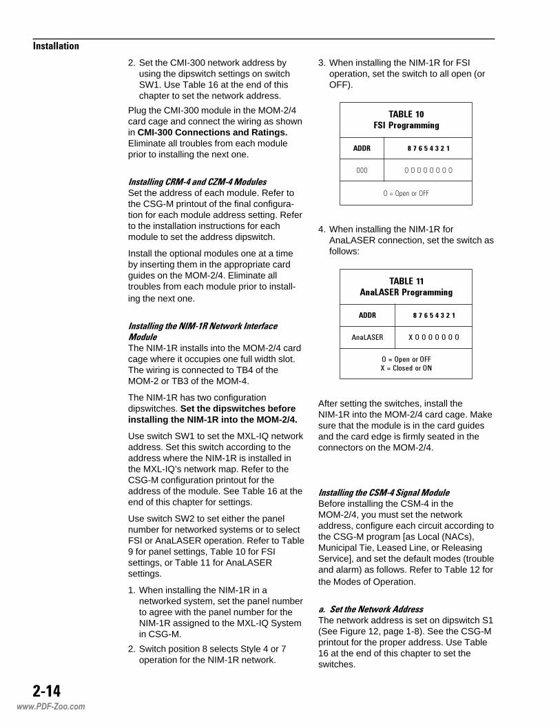
(")6
�����������
2. Set the CMI-300 network address byusing the dipswitch settings on switchSW1. Use Table 16 at the end of thischapter to set the network address.
Plug the CMI-300 module in the MOM-2/4card cage and connect the wiring as shownin CMI-300 Connections and Ratings.Eliminate all troubles from each moduleprior to installing the next one.
(��������,�$#���� �,9$#��$� ���Set the address of each module. Refer tothe CSG-M printout of the final configura-tion for each module address setting. Referto the installation instructions for eachmodule to set the address dipswitch.
Install the optional modules one at a timeby inserting them in the appropriate cardguides on the MOM-2/4. Eliminate alltroubles from each module prior to install-ing the next one.
(������������($#)����������(������ �$� ��The NIM-1R installs into the MOM-2/4 cardcage where it occupies one full width slot.The wiring is connected to TB4 of theMOM-2 or TB3 of the MOM-4.
The NIM-1R has two configurationdipswitches. Set the dipswitches beforeinstalling the NIM-1R into the MOM-2/4.
Use switch SW1 to set the MXL-IQ networkaddress. Set this switch according to theaddress where the NIM-1R is installed inthe MXL-IQ’s network map. Refer to theCSG-M configuration printout for theaddress of the module. See Table 16 at theend of this chapter for settings.
Use switch SW2 to set either the panelnumber for networked systems or to selectFSI or AnaLASER operation. Refer to Table9 for panel settings, Table 10 for FSIsettings, or Table 11 for AnaLASERsettings.
1. When installing the NIM-1R in anetworked system, set the panel numberto agree with the panel number for theNIM-1R assigned to the MXL-IQ Systemin CSG-M.
2. Switch position 8 selects Style 4 or 7operation for the NIM-1R network.
3. When installing the NIM-1R for FSIoperation, set the switch to all open (orOFF).
'������(��))��(%�����
**� ���$+&,-
���
99 $��#� =
4. When installing the NIM-1R forAnaLASER connection, set the switch asfollows:
�������(��))��(%���������
**� ���$+&,-
�������� �������
���� ��������� �����
After setting the switches, install theNIM-1R into the MOM-2/4 card cage. Makesure that the module is in the card guidesand the card edge is firmly seated in theconnectors on the MOM-2/4.
(�����������,�$#��������$� ��Before installing the CSM-4 in theMOM-2/4, you must set the networkaddress, configure each circuit according tothe CSG-M program [as Local (NACs),Municipal Tie, Leased Line, or ReleasingService], and set the default modes (troubleand alarm) as follows. Refer to Table 12 forthe Modes of Operation.
�:;���������������� ����The network address is set on dipswitch S1(See Figure 12, page 1-8). See the CSG-Mprintout for the proper address. Use Table16 at the end of this chapter to set theswitches.
www.PDF-Zoo.com

(")7
�����������
�:;�������$� �����-!������������.� �,�� ���The CSM-4 has one programming slideswitch and one jumper for each of its twocircuits. (See slide switches S3 and S4 andjumpers G1 and G2 on the CSM-4 board,Figure 12, page 1-8.) Setting these slideswitches and jumpers allows the selectionof four possible modes of operation. Thesemodes correspond with NFPA standards 72Local, Municipal Tie, Leased Line, andNFPA 12A, 13, and 2001 ReleasingService.
Each circuit on the CSM-4 can be setindependently for the type of operationdesired. Table 12 shows how to set theswitches and jumpers for circuits 1 and 2.The CSG-M printout shows the mode foreach circuit.
:;�������1���� ��$� ������-!�������There are two sources of degrade activa-tion, the degrade alarm bus and the de-grade trouble bus. These two busesbecome active ONLY when the MXL-IQcommunication network fails. Dipswitch S2on the CSM-4 sets the degrade mode ofoperation for each circuit.
Each circuit operates independently in thedegrade mode. Dipswitch S2, positionsSW1 and SW2, determines the degrademode of operation when the trouble busactivates. Dipswitch S2, positions SW3-SW6, determines the degrade mode ofoperation when the alarm bus activates.
TABLE 12Modes of Operation
�������$����.��%/�%�����!�/%� %�.�(������
��01�0 ��$�1��(����#
���"2����%� ���%����%�
�0
��'��-,0�6#��-,��0��"�
#��64#),#6#0�:$#�5��),#-#�
#-3"�$�,��)�-")#��-,5#--������#+���
���
�"�����"��"����
�"��"�
���"2����%� $��%����%�
�0
��'��-,0�6#��-,��0��"�
#��64#),#6#0�:$#�5��),#-#�
#-3"�$�,��)�-")#��-,5#--������#+���
���
�"�����"��"����
�"��"�
www.PDF-Zoo.com

(")8
�����������
:;1���� ���������� ��"�����The degrade trouble bus may ONLY beused when the circuit is used as a LeasedLine trouble indicating circuit. (See Table12.) When enabled, this trouble degrademode ensures that a trouble will be trans-mitted to the receiving station even whenthe MXL-IQ communication network fails.
Using the CSG-M printout, determine ifeither of the circuits is configured as aLeased Line trouble. Table 14 shows howto set dipswitch S2 (SW1 and SW2) toenable the degrade trouble activation forthe desired circuit.
$�������� %���"%��� ��(�*�.�(������
���%$����.��%/
���"2����%��3��0
#-3"�$�#��64#),#6����,:��0'#-3"�$���
�4#)�-��� ��#� �..
���"2����%��3��0
#-3"�$�#��64#),#6����,:��0'#-3"�$���
�4#)�-��� ��#� �..
>#����#-3"�$�#��64#),#6$�.4#)"���)���"0$��$����"0$��.
���#���..�#3�)"!&�$��&�)#+0��%)
�:;1���� �����/�� ��"�����Each circuit on the CSM-4 can be set withdipswitch S2, positions SW3-SW6, todetermine when the degrade alarm busactivates (See Table 12). There are threedegrade alarm modes. Each circuit can beset independently from the other.
Determine which type of degrade mode youwant for each circuit and set dipswitch S2(SW3-SW6) as shown in Table 15.
),��*�������-��������-4���
The status of the MXL-IQ before checkoutmust be as listed below:
1. AC and battery power connected andturned on.
2. All modules installed and all field wiringconnected.
3. All initiating devices installed andaddressed.
4. All field wiring checked out.
5. The start-up procedure completed.
6. An CSG-M printout of the summary ofthe System Configuration available.
7. For documentation purposes, set theMXL-IQ time before proceeding.
8. Transfer the final version of the SystemConfiguration to MXL-IQ.
Follow the steps listed in System Opera-tion Checkout.
�<���/�-!��������,� ����
WARNING!Prior to activating any initiating device,take steps to prevent output circuitsfrom being activated. Failure to do somay result in building EVAC (bells),notification of fire department, eleva-tor recall, etc.
Test these operations in accordancewith local codes and follow the direc-tion of the authority having jurisdiction.Observe all safety precautions.
+���������%$����.��%/�� %)����� ��(�*�.�(������
���"2����%� $3� �3�
�����,:��0,#4,$5#4���99 �!,-,#4,$5#4��#:��0,��� ���� �
��,#�#$#����.���99 �7���� �7��7��� � �
��#� �99 ��#� �99 �4#)�-��� �4#)�-���
��#� �99 �4#)�-��� ��#� �99 �4#)�-���
���"2����%� $3� �3�
�����,:��0,#4,$5#4���99 �!,-,#4,$5#4��#:��0,��� ���� �
��,#�#$#����.���99 �7���� �7��7��� � �
��#� �99 ��#� �99 �4#)�-��� �4#)�-���
��#� �99 �4#)�-��� ��#� �99 �4#)�-���
����� �)"!)#4�!#4,$5#4!$,-,#+��<$�)�:$#�")#��-4#),#-$�.4#)"#$,)��"0$�0�#+&���#� �99 #3
www.PDF-Zoo.com

(");
�����������
���������
1. Observe the display on the MKB-4. • The POWER LED should be on steady.
• The TROUBLE LED should be off.
• The following message should appear on the alphanumericdisplay:
��������������� ���������������������������� ��� �
(It may take a few minutes after power-up before the messageSystem Normal appears.)
2. Activate every alarm causing initiatingdevice on the System in groups of 100 orfewer. Reset the System prior toactivating each group of 100.
• Every device alarms and there are no troubles annunciated.
• Device LEDs should come on when the device is in alarm.
• As each device is alarmed, the custom message appears on thedisplay, is recorded on the printer (if installed), and correspondsto the CSG-M printout for that device.
• The messages listed on the printer are in the order in which thedevices were alarmed.
• Pressing the NEXT key on the MKB-4 displays the devices inreverse order.
• Check that all appropriate responses are activated.
3. Activate all supervisory devices on theSystem.
• Each device should cause a supervisory.
• As each device changes state, the custom message appears onthe display, is recorded on the printer (if installed), and corre-sponds to the CSG-M printout for that device.
• The messages listed on the printer are in the order in which thedevices were activated.
• Pressing the NEXT key displays the devices in reverse order.
• Check that all the appropriate responses are activated.
4. Activate all security devices on theSystem.
• Each device should cause a security condition.
• As each device is activated, the custom message appears onthe display, is recorded on the printer (if installed), and corre-sponds to the CSG-M printout for that device.
• Check that all appropriate responses are activated.
www.PDF-Zoo.com

(")<
�����������
��� ������
5. Activate all status devices on theSystem.
• None of the devices should cause an alarm or trouble condition.
• If there is a printer, the System should print the status of report-ing devices.
• As each device is activated, the custom message recorded onthe printer corresponds to the CSG-M printout for that device.
• Check that all appropriate responses are activated.
6. CRM-4 relays:
Refer to Control Output On/Off, page3-38, and toggle each CRM-4 relayassigned to the System.
Reset the System when this test iscomplete.
• Verifies proper operation of the connected relay.
8. System Functions:
Check all functions that are defined inthe customer specifications.
• Check that the correct relationships between initiating devicesand output functions occur as defined by the customer specifica-tions.
• Check that the appropriate NFPA and local codes are met(Refer to the CSG-M Logical Function Summary.)
7. CSM-4 relays:
Refer to Control Output On/Off, page3-38, and toggle each CSM-4 relayassigned to the System.
Reset the System when this test iscomplete.
• Verifies proper operation of the connected relay.
www.PDF-Zoo.com
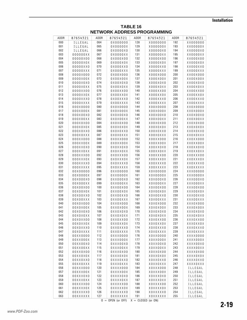
(")=
�����������
���� � � � � � � � � ���� � � � � � � � � ���� � � � � � � � � ���� � � � � � � � �
���
���
���
���
���
��
��
���
���
��
���
���
���
���
���
��
��
���
���
��
���
���
���
���
���
��
��
���
���
��
���
���
���
���
���
��
��
���
���
��
���
���
���
���
���
��
��
���
���
��
��
��
��
��
��
�
�
��
��
�
��
��
��
��
�� � � � � � �
�� � � � � � �
�� � � � � � �
�� � � � � � � �
�� � � � � � � �
�� � � � � � � �
�� � � � � � � �
�� � � � � � � �
�� � � � � � � �
�� � � � � � � �
�� � � � � � � �
�� � � � � � � �
�� � � � � � � �
�� � � � � � � �
�� � � � � � � �
�� � � � � � � �
�� � � � � � � �
�� � � � � � � �
�� � � � � � � �
�� � � � � � � �
�� � � � � � � �
�� � � � � � � �
�� � � � � � � �
�� � � � � � � �
�� � � � � � � �
�� � � � � � � �
�� � � � � � � �
�� � � � � � � �
�� � � � � � � �
�� � � � � � � �
�� � � � � � � �
�� � � � � � � �
�� � � � � � � �
�� � � � � � � �
�� � � � � � � �
�� � � � � � � �
�� � � � � � � �
�� � � � � � � �
�� � � � � � � �
�� � � � � � � �
�� � � � � � � �
�� � � � � � � �
�� � � � � � � �
�� � � � � � � �
�� � � � � � � �
�� � � � � � � �
�� � � � � � � �
�� � � � � � � �
�� � � � � � � �
�� � � � � � � �
�� � � � � � � �
�� � � � � � � �
�� � � � � � � �
�� � � � � � � �
�� � � � � � � �
�� � � � � � � �
�� � � � � � � �
�� � � � � � � �
�� � � � � � � �
�� � � � � � � �
�� � � � � � � �
�� � � � � � � �
�� � � � � � � �
�� � � � � � � �
��
�
�
��
��
�
���
���
���
���
���
��
��
���
���
��
���
���
���
���
���
��
��
���
���
��
� �
� �
� �
� �
� �
�
�
� �
� �
�
���
���
���
���
���
��
��
���
���
��
���
���
���
���
���
��
��
���
���
��
���
���
���
���
���
��
��
���
�� � � � � � � �
�� � � � � � � �
�� � � � � � � �
�� � � � � � � �
�� � � � � � � �
�� � � � � � � �
�� � � � � � � �
�� � � � � � � �
�� � � � � � � �
�� � � � � � � �
�� � � � � � � �
�� � � � � � � �
�� � � � � � � �
�� � � � � � � �
�� � � � � � � �
�� � � � � � � �
�� � � � � � � �
�� � � � � � � �
�� � � � � � � �
�� � � � � � � �
�� � � � � � � �
�� � � � � � � �
�� � � � � � � �
�� � � � � � � �
�� � � � � � � �
�� � � � � � � �
�� � � � � � � �
�� � � � � � � �
�� � � � � � � �
�� � � � � � � �
�� � � � � � � �
�� � � � � � � �
�� � � � � � � �
�� � � � � � � �
�� � � � � � � �
�� � � � � � � �
�� � � � � � � �
�� � � � � � � �
�� � � � � � � �
�� � � � � � � �
�� � � � � � � �
�� � � � � � � �
�� � � � � � � �
�� � � � � � � �
�� � � � � � � �
�� � � � � � � �
�� � � � � � � �
�� � � � � � � �
�� � � � � � � �
�� � � � � � � �
�� � � � � � � �
�� � � � � � � �
�� � � � � � � �
�� � � � � � � �
�� � � � � � � �
�� � � � � � � �
�� � � � � � � �
�� � � � � � � �
�� � � � � � � �
�� � � � � � � �
�� � � � � � � �
�� � � � � � � �
�� � � � � � � �
�� � � � � � � �
���
��
���
���
���
���
���
��
��
���
���
��
���
���
���
���
���
��
��
���
���
��
��
��
��
��
��
�
�
��
��
�
��
��
��
��
��
�
�
��
��
�
���
���
���
���
���
��
��
���
���
��
���
���
���
���
���
��
��
���
���
��
� �
� �
�� � � � � � � �
�� � � � � � � �
�� � � � � � � �
�� � � � � � � �
�� � � � � � � �
�� � � � � � � �
�� � � � � � � �
�� � � � � � � �
�� � � � � � � �
�� � � � � � � �
�� � � � � � � �
�� � � � � � � �
�� � � � � � � �
�� � � � � � � �
�� � � � � � � �
�� � � � � � � �
�� � � � � � � �
�� � � � � � � �
�� � � � � � � �
�� � � � � � � �
�� � � � � � � �
�� � � � � � � �
�� � � � � � � �
�� � � � � � � �
�� � � � � � � �
�� � � � � � � �
�� � � � � � � �
�� � � � � � � �
�� � � � � � � �
�� � � � � � � �
�� � � � � � � �
�� � � � � � � �
�� � � � � � � �
�� � � � � � � �
�� � � � � � � �
�� � � � � � � �
�� � � � � � � �
�� � � � � � � �
�� � � � � � � �
�� � � � � � � �
�� � � � � � � �
�� � � � � � � �
�� � � � � � � �
�� � � � � � � �
�� � � � � � � �
�� � � � � � � �
�� � � � � � � �
�� � � � � � � �
�� � � � � � � �
�� � � � � � � �
�� � � � � � � �
�� � � � � � � �
�� � � � � � � �
�� � � � � � � �
�� � � � � � � �
�� � � � � � � �
�� � � � � � � �
�� � � � � � � �
�� � � � � � � �
�� � � � � � � �
�� � � � � � � �
�� � � � � � � �
�� � � � � � � �
�� � � � � � � �
� �
� �
� �
�
�
� �
� �
�
���
���
���
���
���
��
��
���
���
��
���
���
���
���
���
��
��
���
���
��
���
���
���
���
���
��
��
���
���
��
���
���
���
���
���
��
��
���
���
��
���
���
���
���
���
��
��
���
���
��
��
��
��
��
��
�
�� � � � � � � �
�� � � � � � � �
�� � � � � � � �
�� � � � � � � �
�� � � � � � � �
�� � � � � � � �
�� � � � � � � �
�� � � � � � � �
�� � � � � � � �
�� � � � � � � �
�� � � � � � � �
�� � � � � � � �
�� � � � � � � �
�� � � � � � � �
�� � � � � � � �
�� � � � � � � �
�� � � � � � � �
�� � � � � � � �
�� � � � � � � �
�� � � � � � � �
�� � � � � � � �
�� � � � � � � �
�� � � � � � � �
�� � � � � � � �
�� � � � � � � �
�� � � � � � � �
�� � � � � � � �
�� � � � � � � �
�� � � � � � � �
�� � � � � � � �
�� � � � � � � �
�� � � � � � � �
�� � � � � � � �
�� � � � � � � �
�� � � � � � � �
�� � � � � � � �
�� � � � � � � �
�� � � � � � � �
�� � � � � � � �
�� � � � � � � �
�� � � � � � � �
�� � � � � � � �
�� � � � � � � �
�� � � � � � � �
�� � � � � � � �
�� � � � � � � �
�� � � � � � � �
�� � � � � � � �
�� � � � � � � �
�� � � � � � � �
�� � � � � � � �
�� � � � � � � �
�� � � � � � � �
�� � � � � � � �
�� � � � � � � �
�� � � � � � � �
�� � � � � � �
�� � � � � � �
�� � � � � � �
�� � � � � � �
�� � � � � � �
�� � � � � � �
�� � � � � � �
�� � � � � � �
�� �� ����� ���� ����� � � �� �� ������� ���� ���
TABLE 16NETWORK ADDRESS PROGRAMMING
www.PDF-Zoo.com

("(?
�����������
www.PDF-Zoo.com

This section provides instructions foroperating the MXL-IQ Control Panel.Please review the introduction to theMXL-IQ Control Panel at the beginning ofthis manual.
NOTE: See the Table of Contents pages atthe beginning of this manual for the orderof this chapter. Use it to find the answers tospecific questions when you are workingwith the System.
���������All modules and devices annunciated on theMXL-IQ are identified by an address (MMM-DDD). Each address is in two parts—amodule address (MMM) and a deviceaddress (DDD). The number identifying themodule may be as high as 254, and thenumber identifying the device may be ashigh as 248. Thus a device on a modulemay be identified by any number between001-001 and 253-250. (See Table 17.)
��������������A module may be assigned to any addresson the System, except for some fixedaddresses that have already been assigned(See Table 17). The modules communicateto the MXL-IQ Control Panel through a serialcommunications network. The Systemcontinuously supervises all of the modulesfor presence and proper operation.
You may assign a module to any addresson the System, and assign addresses inany order, mixing different types of mod-
ules and leaving gaps in the numbering,provided you do not use the fixed ad-dresses.
The specific addresses of the Systemmodules are described in Table 17.
���������
�������
�� �������
71ELBATsesserddAeludoMdexiF
eludoMsserddA eludoM
eciveDsserddA)egnaR(
0123***842942052152252352452552
esutonoD)2-BMS(1poolgolanA)2-BMS(2poolgolanA
4-BKM4-BKM4-BKM
1.oN,4-BKMdevreseR
2-BMSM-GSCremmargorP
)devreser(labolG
060-100060-100
052ot100
���www.PDF-Zoo.com

���
���������
���������� ��
�!������ �"!������� �The ALD-2I takes two adjoining moduleaddresses. Loop 1 of the ALD-2I is at anymodule address and loop 2 at the nextaddress. The analog loops on the SMB-2are at module addresses 1 and 2 (SeeTable 17, page 3-1) and cannot be moved.The table below illustrates ALD-2I moduleaddresses:
ALD at ModuleAddresses 3 and 4 DevicesLoop 1 003-001 to 003-060Loop 2 004-001 to 004-060
ALD at ModuleAddresses 15 and 16 DevicesLoop 1 015-001 to 015-060Loop 2 016-001 to 016-060
����#��"�� ���� �The CSM-4 module contains two circuitsand two programmable LEDs.
Their device addresses on the module areas follows:
Circuit 1 001
Circuit 2 002
LED 1 005
LED 2 006
For example, the address of circuit 2 on theCSM-4 at module address 3 is 003-002.
� ��# � ������ �The CRM-4 Relay module contains fourrelays and two controllable LEDs.
Their device addresses on the module areas follows:
Relay 1 001
Relay 2 002
Relay 3 003
Relay 4 004
LED 1 005
LED 2 006
For example, the address of relay 4 on theCRM-4 at module address 20 is 020-004.
�$��#���%������� $������� �The CZM-4 Conventional Zone modulecontains four conventional initiating devicezones and two programmable LEDs. Theirdevice addresses on the module are asfollows:
Zone 1 001
Zone 2 002
Zone 3 003
Zone 4 004
LED 1 005
LED 2 006
For example, the address of zone 1 on theCZM-4, at module address 105, is 105-001.
�&'�#&��(����)�����*�����The MKB-4 Keyboard/Annunciator occupiesthe fixed module address 251 (See Table17, page 3-1).
��'������'����The SMB-2 occupies module addresses 1,2, and 253. The module addresses 1 and 2are analog loops.
Module address 253 contains two notifica-tion appliance circuits (NACs) and tworelays. The device addresses at module253 are as follows:
Common alarm relay 001Common trouble relay 002NAC 1 004NAC 2 005
For example, the address of the commonalarm relay at module address 253 is253-001.
��������������� ��
���+,��*���������*��������%��The MOI-7 occupies one network addressand one network node in the MXL-IQSystem. Set the address on S1 (See Figure17, page 1-10) according to Table 16, page2-19, so that it agrees with the addressassigned in CSG-M.
The MOI-7 has a set of 128 subaddressesreserved for the MOD-16 open collector
www.PDF-Zoo.com

���
���������
outputs and MID-16 general purposeinputs. This gives a maximum of 8 MOD-16boards and 8 MID-16 boards.
The MOI-7 subaddress map is as follows.
001-016 MOD-16/MID-16 #1017-032 MOD-16/MID-16 #2033-048 MOD-16/MID-16 #3049-064 MOD-16/MID-16 #4065-080 MOD-16/MID-16 #5081-096 MOD-16/MID-16 #6097-112 MOD-16/MID-16 #7113-128 MOD-16/MID-16 #8
The MOI-7 has two status LEDs:
The TRANSMIT LED indicates that theMOI-7 is sending information to the SMB-2.During normal operation this LED flashesperiodically when the SMB-2 requests theMOI-7’s status.
The TROUBLE LED only lights when theMOI-7 cannot communicate with theMXL-IQ. This is an indication that thenetwork connection between the MOI-7 andSMB-2 is damaged.
�����-.������ �*������������� �/The MOD-16 does not occupy a networkaddress. The MOD-16 is at a subaddressof the MOI-7 to which it is connected. Thesubaddresses of any given MOD-16s aredetermined by their position in the string ofMOD-16s.
The output cable from the MOI-7 connectsto the first MOD-16, which has thesubaddress of 001-016 as shown above.Each additional MOD-16 in the chain hasthe next block of 16 addresses.
You may connect a maximum of 8MOD-16s and MID-16s to an individualMOI-7 for a total of 128 open collectoroutputs and 128 general purpose inputs.
����"�0��&'�#&��(����)�����*�����1��� ��!�*� ����See Figure 32, page 3-4, for the location ofthe display keys and LEDs.
When the MKB-4 Keyboard/ AnnunciatorPanel is installed, only the display, LEDs,and display control keys are visible. TheACKnowledge keys and other controls arehidden behind a locked door. Unlock andopen the door to gain access to those keysand controls.
�0����� ��The display has two lines of 40 characterseach. What is shown on the display de-pends on the state of the System. Thedisplay contains a back light which turns onautomatically when any key is pressed oran event is reported. The back light turnsoff automatically after 5 minutes of systeminactivity.
The System has several displays. Whenthe System is Normal, the display shows:
���������� ��������������� � ����
When an event has been annunciated, theSystem alternates between the followingthree displays:
����������������� ��� ��������������������������������������������������������������������
����������������������� ���!����"#$������������� �������������������!��!"%#�������%�&�����������������
���'!!!������������(��)�������'!!!�������'!!!������������� �������'!!!
www.PDF-Zoo.com

��#
���������
The terms used in the displays describedabove are defined as follows:
• ACK appears if the event has beenacknowledged; otherwise, the field isblank.
• IN is displayed when a condition occurs.
• OUT is displayed when a normal state isrestored.
• [time/date] shows the time and date theevent occurred.
������ ����( �� ���The internal audible alarm (not visible)sounds steadily when there is an unac-knowledged fire alarm. It pulses if allalarms are acknowledged, but there is atleast one supervisory, trouble, or securitycondition.
��0����� ��A 2-line display of 40 characters each thatshows the state of the System. A back lightturns on when any key is pressed or anevent is reported.
������������� &�����ALARM ACK - Press to acknowledge afire alarm.
AUD SIL - Press to silence or unsilencea notification appliance circuit.
SUPV ACK - Press to acknowledge asupervisory.
TRBL ACK - Press to acknowledge atrouble.
SEC ACK - Press to acknowledge asecurity condition.
RESET - Press to reset the System.
�������*&�����Use the numeric keypad (keys 0 through 9)when the System asks for a model number,device number, password, time, date, orother information. The display shows eachnumber as you press the key (except whenyou enter a password; the System showsan asterisk for each digit of the passwordthat you type).
Figure 32MKB-4 Keyboard/Annunciator Panel
www.PDF-Zoo.com

��2
���������
����� �������
The MXL-IQ has two display keys, NEXTand HOLD, located on the MKB-4.
NEXT - Press NEXT to show the previousitem in a list of Alarms, Supervisories,Troubles, or Security conditions.
HOLD - Press HOLD at any time to freezethe present display. The display remainsfrozen until HOLD is released.
�����
ALARM - This red LED flashes when thereis at least one unacknowledged fire alarm;it glows steadily when all fire alarms areacknowledged.
AUDIBLE SILENCE - This red LED flasheswhen at least one notification appliancecircuit (NAC) is active; it glows steadilywhen all silenceable NACs are silenced.Under normal conditions, the LED is off.
SUPERVISORY - This yellow LED flasheswhen there is at least one unacknowledgedsupervisory; it glows steadily when allsupervisories are acknowledged.
TROUBLE - This yellow LED flashes whenthere is at least one unacknowledgedtrouble; it glows steadily when all troublesare acknowledged.
SECURITY - This yellow LED flashes whenthere is at least one unacknowledgedsecurity condition; it glows steadily when allsecurity conditions are acknowledged.
POWER - This green LED glows steadily toindicate that the AC power is on; it flasheswhen the System is on battery backup.
PARTIAL SYSTEM DISABLE - This yellowLED glows steadily when any device isdisabled.
������3���������The MXL-IQ alphanumeric display annun-ciator has five modes of operation:
1. Alarm2. Supervisory3. Trouble4. Security5. Normal
�������������
Left arrow (�) - Press to select the item tothe left of what is flashing on the display(unless entering a number).
Right arrow (�) - Press to select the item tothe right of what is flashing on the display(unless entering a number).
Up arrow (�) - Press to go back to theprevious item.
ENTER - Press to select the item on whichthe cursor is flashing. When typing innumbers, press ENTER when finished tocomplete the entry.
PRINT - Press to print selected lists andreports.
FORM FEED - Press to advance the paperin the printer.
CLEAR - Press to cancel printing begun bypressing PRINT. The System will print:
�������������� ����������� �������
HELP - Press to display a one-line helpmessage.
��0����*�� .�!�������*����/&�����Use the four function keys alone or incombination with ALT1 or ALT2 to providea total of 12 special functions. When usinga combination, hold the ALT key down andthen press the function key.
F1F2F3F4ALT1-F1ALT1-F2ALT1-F3ALT1-F4 Hold ALT, then pressALT2-F1 function key.ALT2-F2ALT2-F3ALT2-F4
The special function keys are defined usingthe CSG-M Custom Software Generator(See CSG-M Programming Manual, P/N315-090381). These definitions can berecorded in the box on the panel.
�� �������
www.PDF-Zoo.com
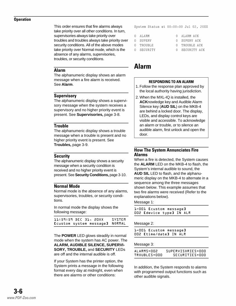
��-
���������
This order ensures that fire alarms alwaystake priority over all other conditions. In turn,supervisories always take priority overtroubles and troubles always take priority oversecurity conditions. All of the above modestake priority over Normal mode, which is theabsence of any alarms, supervisories,troubles, or security conditions.
� ���The alphanumeric display shows an alarmmessage when a fire alarm is received.See Alarm.
�����%�����The alphanumeric display shows a supervi-sory message when the system receives asupervisory and no higher priority event ispresent. See Supervisories, page 3-8.
����( �The alphanumeric display shows a troublemessage when a trouble is present and nohigher priority event is present. SeeTroubles, page 3-9.
��*�����The alphanumeric display shows a securitymessage when a security condition isreceived and no higher priority event ispresent. See Security Conditions, page 3-10.
����� ����Normal mode is the absence of any alarms,supervisories, troubles, or security condi-tions.
In normal mode the display shows thefollowing message:
**+,-+,-�.� �/*0�1�22 ������� "���%������%�%����3�� ����
The POWER LED glows steadily in normalmode when the system has AC power. TheALARM, AUDIBLE SILENCE, SUPERVI-SORY, TROUBLE, and SECURITY LEDsare off and the internal audible is off.
If your System has the printer option, theSystem prints a message in the followingformat every day at midnight, even whenthere are alarms or other conditions:
����� ��������������������������������
�������� ������������
���� !"�# ���� !"�#����
�����$ %�" �����$ %�"����
����"� �&�' ����"� �&�'����
� ���
4�1����5�����!� �1. Follow the response plan approved by
the local authority having jurisdiction.
2. When the MXL-IQ is installed, theACKnowledge key and Audible AlarmSilence key (AUD SIL) on the MKB-4are behind a locked door. The display,LEDs, and display control keys arevisible and accessible. To acknowledgean alarm or trouble, or to silence anaudible alarm, first unlock and open thedoor.
6�7�0������������*���������� ����When a fire is detected, the System causesthe ALARM LED on the MKB-4 to flash, theSystem’s internal audible to sound, theAUD SIL LED to flash, and the alphanu-meric display on the MKB-4 to alternate in asequence among the three messagesshown below. This example assumes thattwo fire alarms were received (Refer to theexplanations below).Message 1:
*4��*�� "���%�%����3����1������ ������������
Message 2:
*4��*�� "���%�%����3����1����%�&����������
Message 3:
���'��1 ��(��)�������'����������'��� �� �������'���
In addition, the System responds to alarmswith programmed output functions such asother audible signals.
www.PDF-Zoo.com

��+
���������
In the messages above, 1-001 representsthe address of the device reporting thealarm.
NOTE: On the display, not all leadingzeros are shown. If your Systemincludes a printer, note that theleading zeros are not shown.
002 in the first message tells you that this isthe second (and the most recent) of twoalarms received.
The status information in the third messagereports the total of alarms, supervisories,troubles, and security conditions.
If your System includes a printer, it prints amessage from two to four lines long similarto the following:
������()(�((�*+�*+�,"��-(������
.(�/0���1 � �����2��/��3�0�����2
In the preceding printed message, ALARMindicates that the type of occurrence is afire alarm; 1-1 is the device address; #1 isthe number of the alarm in the list of firealarms; [custom message] is a custommessage entered using the CSG-M Cus-tom Software Generator (See the CSG-MProgramming Manual, P/N 315-090381);[device type] is the type of device whichreported the alarm.
,��7��"�0�!����3� ����To see the alarm list when there is morethan one alarm, press NEXT on the MKB-4(the System displays the most recent alarmfirst).
6�7��' �*8�*8��7 ��"������� ���.��1�+�!�*� 9����*��� ���9��� ������������/1. Note the specific location of the alarm(s)
by using the procedures describedabove.
2. Unlock and open the door.
3. Press ALARM ACK to acknowledge allalarms. The System displays thefollowing message:
����� ���5�.6�.7
4. If your System includes the printeroption, it prints the following message:
����������((�*+�*+�,"��-(�����
��������������4$5�",6",
5. If you press ALARM ACK again, theSystem displays ALL ALARMSACKNOWLEDGED.
The ALARM LED glows steadily toindicate that all alarms are acknowledged.If there are no supervisories, troubles, orsecurity conditions in the System, theinternal audible goes silent; if any ofthose conditions still exist, the internalaudible pulses.
6�7�����%���� ��*8��7 ��"������� ���.��1�+�1����������9�!�:+-/1. Press ALARM ACK. The System
acknowledges the alarm displayed andthen displays the next unacknowledgedalarm.
If your System has the printer option, itprints an alarm acknowledgmentmessage similar to the following:
�����*4,�*1+�*+18�.� �/*01�2291�� "���%�%����3��0������ �������
Note that the acknowledgmentsmessage includes the term ACK toindicate this alarm was acknowledged.
2. Continue acknowledging alarms asexplained above until the Systemdisplays the following message: ALLALARMS ACKNOWLEDGED.
The ALARM LED glows steadily toindicate that all alarms are acknowl-edged. If there are no supervisories,troubles, or security conditions still in theSystem, the internal audible goes silent;if any of those conditions still exist, theinternal audible pulses.
3. If your System includes a printer, it printsa message similar to the following:
����������(���*�77�,"��-(�����
��������������4$5�",6",
�� ��*��"�0�������Press AUD SIL after all alarms are ac-knowledged. The System displays thefollowing message: AUDIBLES SILENCED.(Pressing AUD SIL a second time causesthe internal audible and the System tounsilence and the message AUDIBLESUNSILENCED to appear on the display;
www.PDF-Zoo.com

��;
���������
thus, pressing AUD SIL alternately silencesand unsilences the System.)
If your System has a printer, it prints amessage similar to the following:
� ,��&�"4�",8 4�&���((��(����,"��-(������
� ,&%�"���&�"4�",
�����%�������
6�7�0������������*����������%�������When a supervisory is detected, theSystem causes the SUPERVISORY LEDon the MKB-4 to flash, the System’sinternal audible to sound, and the alphanu-meric display on the MKB-4 to alternate in asequence among the three messagesshown below. This example assumes thattwo supervisories were received (See theexplanations below).
Message 1:
*4��*����������� ���1�������������������(
Message 2:
*4��*����������� ���1�����������������(
Message 3:
���'��� ��(��)�������'��1�������'��� �� �������'���
In addition, the System responds tosupervisories with programmed outputfunctions such as other audible signals.
In the messages above, 1-001 representsthe address of the device reporting thesupervisory.
002 in the first message tells you that this isthe second (and the most recent) of twosupervisories received.
The status information in the third messagereports the total of alarms, supervisories,troubles, and security conditions.
If your System includes a printer, it prints amessage from two to four lines long similarto the following:
� !"�#�()(�((�*+�*+�,"��-(������
.(�������������� �����������
In the preceding message, SUPERVindicates that the type of occurrence is asupervisory; 1-1 is the device address; #1is the number of the supervisory in the listof supervisories; [custom message] is acustom message entered using the CSG-MCustom Software Generator (See the CSG-MProgramming Manual, P/N 315-090381);[device type] is the type of device whichreported the supervisory.
,��7��"�0�!����3�����%�������To see the supervisory list when there ismore than one supervisory, press NEXT onthe MKB-4 (the System displays the mostrecent supervisory first).
6�7��' �*8�*8��7 ��"�������%�����.��1�+�!�*� 9����*��� ���9��� ������������/1. Note the specific location of the
supervisories by using the proceduresdescribed above.
2. Unlock and open the door.
3. Press SUPV ACK to acknowledge allsupervisories. The System displays thefollowing message:
���(��)�������� ���5�.6�.7
4. If your System includes a printer, it printsthe following message:
����� !"�#&�$�'�((�*+�*+�,"��-(�����
����� !"�#&�$�&"�����4$5�",6",
5. If you press SUPV ACK again, theSystem displays ALL SUPERVISORIESACKNOWLEDGED.
The SUPERVISORY LED glows steadilyto indicate that all supervisories areacknowledged. If there are no troubles orsecurity conditions in the System, theinternal audible goes silent; if any ofthose conditions still exist, the internalaudible pulses.
www.PDF-Zoo.com

��<
���������
Message 2:
*4��*���������������1�����������������
Message 3:
���'��� ��(��)�������'����������'��1 �� �������'���
In addition, the System responds totroubles with programmed output functions.
In the messages above, 1-001 representsthe address of the device reporting thetrouble.
002 in the first message tells you that this isthe second (and the most recent) of twotroubles received.
The status information in the third messagereports the total of alarms, supervisories,troubles, and security conditions.
If your System includes a printer, it prints amessage from two to four lines long similarto the following:
6�7�����%���� ��*8��7 ��"�������%�����.��1�+�1����������9�!�:+-/1. Press SUPV ACK. The System
acknowledges the supervisory displayedand then displays the nextunacknowledged supervisory.
If your system has a printer, it prints anacknowledgment message similar to thefollowing:
����� !"�#�()*�(���(��9�,"��-�����
.��������������� �����������
Note that the acknowledgment messageincludes the term ACK to indicate thissupervisory was acknowledged.
2. Continue acknowledging supervisoriesas explained above until the Systemdisplays the following message: ALLSUPERVISORIES ACKNOWLEDGED.
The SUPERVISORY LED glows steadilyto indicate that all supervisories areacknowledged. If there are no troubles orsecurity conditions still in the System, theinternal audible goes silent; if any ofthose conditions still exist, the internalaudible pulses.
3. If your System includes a printer, it printsthe following message:
����� !"�#&�$�'�(���*�77�,"��-�����
����� !"�#&�$�&"�����4$5�",6",
����( ��
6�7�0������������*���������( ��When a trouble is detected, the Systemcauses the TROUBLE LED on the MKB-4to flash, the System’s internal audible tosound, and the alphanumeric display on theMKB-4 to alternate in a sequence amongthe three messages shown below. Thisexample assumes that two troubles werereceived (See the explanations below).
Message 1:
*4��*����������� ���1��������������������
��$ %�"�&4�()(�((�*+�*+�,"��-(������
.(������������������������� ����������
In the above printed message, TROUBLEindicates that the type of occurrence is atrouble; 1-1 is the device address; and #1 isthe number of troubles in the list of troubles;[custom message] is a custom messageentered using the CSG-M Custom SoftwareGenerator (See the CSG-M ProgrammingManual, P/N 315- 090381); [trouble type]is the type of trouble which reported;[device type] is the type of device introuble.
,��7��"�0�!����3����( ��To see the trouble list when there is morethan one trouble, press NEXT on theMKB-4 (the System displays the mostrecent trouble first).
www.PDF-Zoo.com

���:
���������
6�7��' �*8�*8��7 ��"������( �.��1�+�!�*� 9����*��� ���9��� ������������/1. Note the specific location of the
trouble(s) by using the proceduresdescribed above.
2. Unlock and open the door.
3. Press TRBL ACK to acknowledge alltroubles. The System displays thefollowing message: ALL TROUBLESACKNOWLEDGED.
4. If your System includes a printer, it printsthe following message:
������$ %�"�((�*+�*+�,"��-(������
������$ %�"�����4$5�",6",
5. If you press TRBL ACK again, theSystem displays
��������� ���5�.6�.7
The TROUBLE LED glows steadily to in-dicate that all troubles are acknowledged.If there are no security conditions in theSystem, the internal audible goes silent;if any security conditions still exist, theinternal audible pulses.
6�7�����%���� ��*8��7 ��"������( �.��1�+�1����������9�!�:+-/1. Press TRBL ACK. The System
acknowledges the trouble displayed andthen displays the next unacknowledgedtrouble.
If your System has a printer, it prints anacknowledgment message similar to thefollowing:
������$ %�"�()*�(���(��9�,"��-(�����
.��/0���1 � �����2��/��1�:������2�
/��3�0�����2
Note that the acknowledgment messageincludes the term ACK to indicate thistrouble was acknowledged.
2. Continue acknowledging troubles asexplained above until the Systemdisplays the following message:
��������� ���5�.6�.7
The TROUBLE LED glows steadily toindicate that all troubles are acknowl-edged. If there are no security conditionsstill in the System, the internal audiblegoes silent; if any of those conditions stillexist, the internal audible pulses.
3. If your System includes a printer, it printsthe following message:
������$ %�"�(���*�77�,"��-(������
������$ %�"�����4$5�",6",
��*�����
6�7�0������������*�������*���������������When a security condition is detected, theSystem causes the SECURITY LED on theMKB-4 to flash, the System’s internalaudible to sound, and the alphanumericdisplay on the MKB-4 to alternate in asequence among the three messagesshown below. This example assumes thattwo security conditions were received (Seethe explanations below the messages).
Message 1:
*4��*����������� ���1�������������������
Message 2:
*4��*����������� ���1�����������������
Message 3:
���'���������(��)�������'����������'���������� �������'��1
In addition, the System responds to securityconditions with programmed output functions.
In the messages above, 1-001 representsthe address of the device reporting thesecurity condition.
002 in the first message tells you that this isthe second (and the most recent) of twosecurity conditions received.
www.PDF-Zoo.com

����
���������
The status information in the third messagereports the total number of alarms, super-visories, troubles, and security conditions.
If your System includes a printer, it prints amessage from two to four lines long similarto the following:
�"� �&�'�&4�()(�((�*+�*+�,"��-(������
.(�������������� �����������
In the preceding printed message, SECU-RITY indicates that the type of occurrenceis a security condition; 1-1 is the deviceaddress; #1 is the number of the securitycondition in the list of security conditions;[custom message] is a custom messageentered using the CSG-M Custom SoftwareGenerator (See the CSG-M ProgrammingManual, P/N 315-090381); [device type] isthe type of device which reported thesecurity condition.
,��7��"�0�!����3��*���������������To see the security condition list when thereis more than one security condition, pressNEXT on the MKB-4 (the System displaysthe most recent security condition first).
6�7�����%���� ��*8��7 ��"����*��������������.�!�:+-/1. Press SEC ACK. The System
acknowledges the security conditiondisplayed and then displays the nextunacknowledged security condition.
If your System has a printer, it prints anacknowledgment message similar to thefollowing:
�����"� �&�'�()*�(���(��9�,"��-�����
.��������������� �����������
Note that the acknowledgment messageincludes the term ACK to indicate thissecurity condition was acknowledged.
2. Continue acknowledging securityconditions as explained above until theSystem displays the following message:ALL SECURITY CONDITIONSACKNOWLEDGED.
The SECURITY LED glows steadily toindicate that all security conditions areacknowledged, and the internal audiblegoes silent.
3. If your System includes a printer, it printsthe following message:
�����"� �&�'�(���*�77�,"��-(������
�����"� �&�'��$4,&�&$4�����4$5�",6",
����1��*������
6��� ����Other terms for Hard Reset are Power-up,Initialization, and Cold Reset.
Applying power to the System performs aHard Reset which initializes (starts) theentire system.
=0���!���>• Alarms, supervisories, troubles, security
conditions
• Any user entries such as time and date
• Arm/disarm
• Manual sensitivity adjustment
• Time-based control until time is reset
=0������!���>• CSG-M program
��3� ����To perform a Soft Reset, press RESET onthe MKB-4 (Refer to Figure 32, page 3-4).Soft reset does not work until you acknowl-edge all alarms, supervisories, troubles,and security conditions and silence theSystem.
=0���!���>• Alarms, supervisories, troubles, security
conditions
• Arm/disarm (unless option disabled byCSG-M)
=0������!���>• Any user entries such as time and date.
• Arm/disarm (when enabled by CSG-M)
• CSG-M program
• Manual sensitivity adjustment
• Time-based control
www.PDF-Zoo.com

����
���������
If you press RESET before acknowledgingall conditions and silencing the audiblealarms, the display shows a messagesimilar to the following:
��������� ���5�.6�.����
(or)
��(��)����������� ���5�.6�.����
(or)
������������� ���5�.6�.����
(or)
�� ����������� ���5�.6�.����
(or)
�.�������������� �.����
If your System has a printer, it prints amessage similar to the following and addsSYSTEM NOT RESET on the bottom line:
�"�"����(�(�*9������-�����
41�������0;�1<������'��������� �41�
������
When the System performs a Soft Reset,the display shows the following message:
������������
The System then returns to Normal modeand the display shows the following:
**+,-+,-�.� �/*0�1�22����������� "���%������%�%����3��������
If your System has a printer, it prints thefollowing message:
�'��"���"�"�
If the System is already in Normal modewhen you press RESET, it displays
�������������������
and does not reset.
����"�0��&'&��(����)�����*�����1��� ��5 �(� ����
The Global MKB Keyboard/AnnunciatorPanel operates the same as describedin Using The MKB Keyboard/AnnunciatorPanel Local Mode, except as noted below.
!����������) �����*�����• As in all networked MXL Systems, the
self-restoring trouble option is notallowed in any MXL.
• An MXL still may only contain a maxi-mum of 4 supervised MKBs. This can bea mix of local and global MKBs.
• BLOCK ACK must be enabled in theCSG-M.
• The maximum number of supervisedGlobal MKBs is 10.
• The maximum number of Global Printersis 2 (not TSP-40s).
5 �(� �&'���� ��������In order to insert the XNET node informa-tion and provide an indication of the numberof events in the System, some of thecharacters in the first and second lineshave been lost.
NN = NODE # (1 - 64)MMM = MODULE # (1 - 253)DDD = DEVICE # (1 - 254)
�!� �The 3 event displays are formatted asfollows for an alarm condition:
��+���4...�� "���%�%����3�� �*����%�&����� ����
��+���4...�� "���%�%����3�� �*������ ������� ����
���'* ��(��)�����'��������'� �� �����'�
www.PDF-Zoo.com
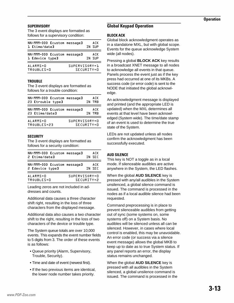
����
���������
��14 ,�� ?The 3 event displays are formatted asfollows for a supervisory condition:
��+���4...�� "���%�%����3�� �*����%�&����� �����(
��+���4...�� "���%�%����3�� �*������ ������� �����(
���'� ��(��)�����'*�������'� �� �����'�
� ��'!4The 3 event displays are formatted asfollows for a trouble condition:
��+���4...�� "���%�%����3�� �1/�����"#$������� ������
��+���4...�� "���%�%����3�� �1/����%�&����� ������
���'� ��(��)�����'��������'1/ �� �����'�
�4�� �?The 3 event displays are formatted asfollows for a security condition:
��+���4...�� "���%�%����3�� �1����%�&����� �����
��+���4...�� "���%�%����3�� �1������ ������� �����
���'� ��(��)�����'��������'� �� �����'1
Leading zeros are not included in ad-dresses and counts.
Additional data causes a three charactershift right, resulting in the loss of threecharacters from the displayed message.
Additional data also causes a two charactershift to the right, resulting in the loss of twocharacters of the device or trouble type.
The System queue totals are over 10,000events. This expands the event number fieldsto 5 digits from 3. The order of these eventsis as follows:
• Queue priority (Alarm, Supervisory,Trouble, Security).
• Time and date of event (newest first).
• If the two previous items are identical,the lower node number takes priority.
5 �(� &��������������
'!��&��&Global block acknowledgment operates asin a standalone MXL, but with global scope.Events for the queue acknowledge Systemwide (all nodes).
Pressing a global BLOCK ACK key resultsin a broadcast XNET message to all nodesto acknowledge all events in that queue.Panels process the event just as if the keypress had occurred at one of its MKBs. Asuccess code (or error code) is sent to theNODE that initiated the global acknowl-edge.
An acknowledgment message is displayedand printed (and the appropriate LED isupdated) when the MXL determines allevents at that level have been acknowl-edged (System wide). The time/date stampof an event is used to determine the truestate of the System.
LEDs are not updated unless all nodesconfirm the acknowledgment has beensuccessfully executed.
����!4��4This key is NOT a toggle as in a localmode. If silenceable audibles are activeanywhere in the System, the LED flashes.
When the global AUD SILENCE key ispressed with any/all audibles in the Systemunsilenced, a global silence command isissued. The command is processed in thenodes as if a local audible silence had beenrequested.
Command preprocessing is in place toprevent silenceable audibles from gettingout of sync (some systems on, somesystems off) on a System basis. Noaudibles will be silenced unless all can besilenced. However, in cases where localcontrol is enabled, this may be unavoidable.An error code (or success via a silenceevent message) allows the global MKB tokeep up to date as to true System status. Ifany panel reports an error, the displaystatus remains unchanged.
When the global AUD SILENCE key ispressed with all audibles in the Systemsilenced, a global unsilence command isissued. The command is processed in the
www.PDF-Zoo.com

���#
���������
nodes as if a local audible unsilence hadbeen requested. An error code (or successvia a silence event message) allows theglobal MKB to keep up to date as to trueSystem status. If any panel reports anerror, the display status changes sincesome audibles have been unsilenced.
4�4�When the global reset key is pressed, eachnode is tested. If all nodes meet theconditions required for reset, the resetcommand is sent and executed. Otherwise,the corresponding error message is dis-played.
�4@�This key operates the same as in the localmode. However, it moves the user throughthe System events globally in the priorityorder established earlier.
6�!�This key operates the same as in the localmode.
���*����&���These keys operates the same as in thelocal MKB.
������*&�����These keys operates the same as in thelocal MKB.
����"�0�����The menu gives you wide control of theMXL-IQ System. You may use the menu nomatter what mode the System is in.
The discussion in this section is in thefollowing order:
• Operation of the keys on the MKB-4Keyboard/Annunciator
• Overview of the menu’s structure
• Beginning a menu session
• Introduction to each of the four menus:
- Acknowledge menu
- List menu
- Control menu
- Test menu
- Entering your password
- Entering module and device numbers
• Using the Acknowledge menu
• Using the List menu
• Using the Control menu
• Using the Test menu
����������3�0�&������0��@!�A�����*�����1��� Use the numeric keypad and the directionaland command keypad when working withthe menu.
������*&�����Use the numeric keypad (keys 0 through 9)when the System asks for a modulenumber, device number, password, time,date, or other information. The displayshows each number as you press the key.However, when you enter a password, theSystem shows asterisks in place of thedigits entered.
�0��������&�����The Command Keypad has both directionaland command keys that are used to movethrough the menu and perform specificfunctions. Refer to Table 18 for a descrip-tion of the Command Keypad.
www.PDF-Zoo.com

���2
���������
�%��%��7�3�0�����B�����*����Press ENTER to enter the menu. Themenu then uses the first 32 spaces of thesecond line of the display to communicatewith you. When you use the Acknowledgeor List menu, the menu uses both lines of thedisplay.
If you are in the menu and do not depress anumeric or arrow key at any time during a 1minute period, the System returns to theprevious item.
The five Main Menu items and their subitemsfor Revision 6.0 and higher follow; theshortened terms used in the menu itself arein parentheses:
�������������� ��
��� ������
� �������������������� ���������
����� ����������������������������
� ������������� ���������
����������������������������������
����� ��
� � �������������������
����� �������������� ���������������
���������� ������������������������
����������� ���� !"
��� ������� ����#�����������������
���� ��������������������������������
�������
�������
�������������������������������
����� ����������������������������������
$������� ������!�!"%��
������������������� ��������� �
�*8��7 ��"������
������ ������������
�� ���
�������
!����
������
�����
������ ������������
�� ���
�������
������������������
� �����
������ �
������� ��
�����������
���
� ���������� ������
���������������
�����
� ��������� �
�� ���� ��
!�����������
����"����
# ��������
�������
���� $��
��%� ���
����������
&����'��
��������
��&�������
������ �
��������
� �������������� ������� ����������������������������������������� �������������������������������������
����
������ (��
������������������
��)�*+
��)�*,
��)�*-
��# ��
��. �*-
��. �*,
��. �*+
���'�����������'����
�����
��������
!������ �' ��
�����
��������
��������/����0
����������/����0
. �����
. ��������
#����$�(1���
�������
�������*����
��%� �*����
&����'%�
�����������
�����������
��&�*�����
2����*����
����������
3� �����������3��*����
������
& ��,
������
��� ����
��2�����
.�������
��./��
���������
����./�
�!4*.���*���
5�#�� �$
��#�� �$
!����
��*�����
/��*� �
������* ���
������* ���
������* ���
���������* ���
�����*���
��)���*2���
��)���*/���
&�� *�����
&�*�����
���*����
�������0
������*������
� �������������� ������� ����������������������������������������������
=� 8���������*��"�
. �*��"�
6 �*��"�
�����*�4.
. �*�4.
6 �*�4.
2����
/7���
www.PDF-Zoo.com
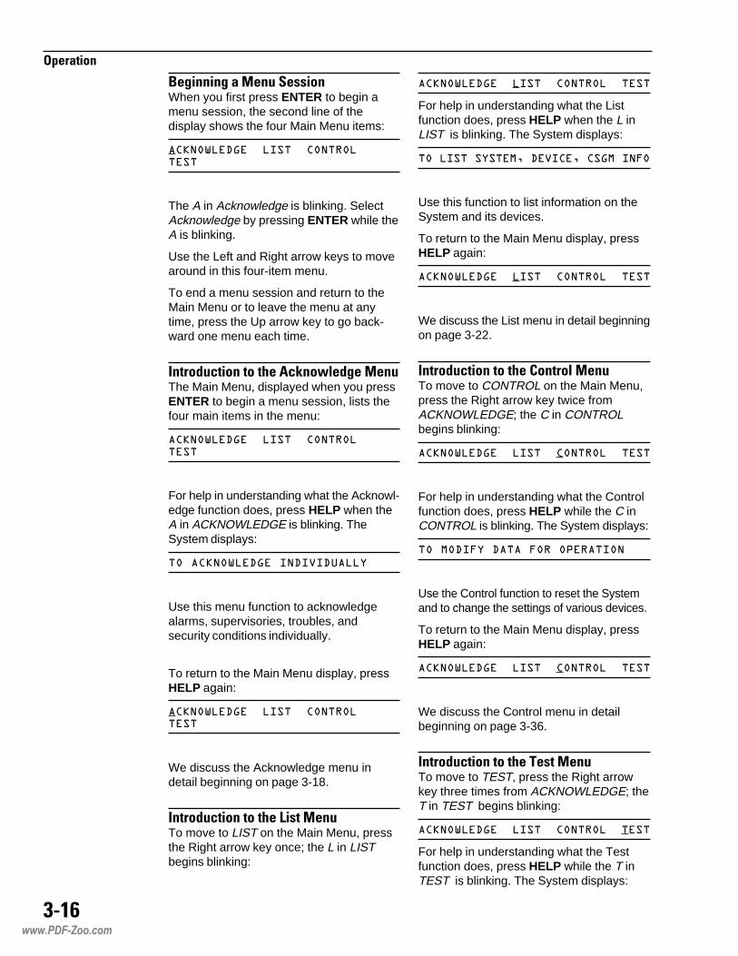
���-
���������
'�"�����"������������When you first press ENTER to begin amenu session, the second line of thedisplay shows the four Main Menu items:
���5�.6�������� ���������
The A in Acknowledge is blinking. SelectAcknowledge by pressing ENTER while theA is blinking.
Use the Left and Right arrow keys to movearound in this four-item menu.
To end a menu session and return to theMain Menu or to leave the menu at anytime, press the Up arrow key to go back-ward one menu each time.
������*�������0��*8��7 ��"�����The Main Menu, displayed when you pressENTER to begin a menu session, lists thefour main items in the menu:
���5�.6�������� ���������
For help in understanding what the Acknowl-edge function does, press HELP when theA in ACKNOWLEDGE is blinking. TheSystem displays:
��� ���5�.6����.�)�.��
Use this menu function to acknowledgealarms, supervisories, troubles, andsecurity conditions individually.
To return to the Main Menu display, pressHELP again:
���5�.6�������� ���������
We discuss the Acknowledge menu indetail beginning on page 3-18.
������*�������0�!�������To move to LIST on the Main Menu, pressthe Right arrow key once; the L in LISTbegins blinking:
���5�.6�������� �����������
For help in understanding what the Listfunction does, press HELP when the L inLIST is blinking. The System displays:
�������������0�.�)� �0� �6����:�
Use this function to list information on theSystem and its devices.
To return to the Main Menu display, pressHELP again:
���5�.6�������� �����������
We discuss the List menu in detail beginningon page 3-22.
������*�������0������� ����To move to CONTROL on the Main Menu,press the Right arrow key twice fromACKNOWLEDGE; the C in CONTROLbegins blinking:
���5�.6�������� �����������
For help in understanding what the Controlfunction does, press HELP while the C inCONTROL is blinking. The System displays:
�����.�:��.��:����(������
Use the Control function to reset the Systemand to change the settings of various devices.
To return to the Main Menu display, pressHELP again:
���5�.6�������� �����������
We discuss the Control menu in detailbeginning on page 3-36.
������*�������0���������To move to TEST, press the Right arrowkey three times from ACKNOWLEDGE; theT in TEST begins blinking:
���5�.6�������� �����������
For help in understanding what the Testfunction does, press HELP while the T inTEST is blinking. The System displays:
www.PDF-Zoo.com
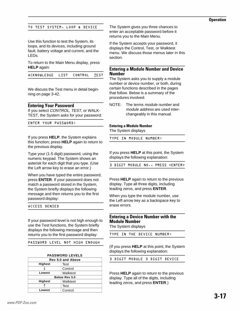
���+
���������
��������������0���(�;�.�)� �
Use this function to test the System, itsloops, and its devices, including groundfault, battery voltage and current, and theLEDs.
To return to the Main Menu display, pressHELP again:
���5�.6�������� �����������
We discuss the Test menu in detail begin-ning on page 3-42.
4������"?���1���7���If you select CONTROL, TEST, or WALK-TEST, the System asks for your password:
�����������(��5��.+
If you press HELP, the System explainsthis function; press HELP again to return tothe previous display.
Type your (1-5 digit) password, using thenumeric keypad. The System shows anasterisk for each digit that you type. (Usethe Left arrow key to erase an error.)
When you have typed the entire password,press ENTER. If your password does notmatch a password stored in the System,the System briefly displays the followingmessage and then returns you to the firstpassword display:
����.����.
If your password level is not high enough touse the Test functions, the System brieflydisplays the following message and thenreturns you to the first password display:
(��5��.��)������<�6<�����6<
PASSWORD LEVELSRev 5.0 and Above
Highest Test� Control
Lowest WalktestBelow Rev 5.0
Highest Walktest� Test
Lowest Control
The System gives you three chances toenter an acceptable password before itreturns you to the Main Menu.
If the System accepts your password, itdisplays the Control, Test, or Walktestmenu. We discuss those menus later in thissection.
4������"����� ����(�������%�*����(��The System asks you to supply a modulenumber or device number, or both, duringcertain functions described in the pagesthat follow. Below is a summary of theprocedures involved.
NOTE: The terms module number andmodule address are used inter-changeably in this manual.
4������"����� ����(��The System displays
��(�������.���������+
If you press HELP at this point, the Systemdisplays the following explanation:
/�.�6�����.�����70�(�����=�����>
Press HELP again to return to the previousdisplay. Type all three digits, includingleading zeros, and press ENTER.
When you type the module number, usethe Left arrow key as a backspace key toerase errors.
4������"���%�*����(��7��0�0����� ����(��The System displays
��(������<��.�)� ��������+
(If you press HELP at this point, the Systemdisplays the following explanation:
/�.�6�����.���/�.�6���.�)� �
Press HELP again to return to the previousdisplay. Type all of the digits, includingleading zeros, and press ENTER.)
www.PDF-Zoo.com

���;
���������
When you type the module number andthe device number, use the Left arrowkey as a backspace key to erase errors.
��&��=!4�54����The Acknowledge menu has four itemsfrom which to choose; the shortenedterms used in the menu itself are inparentheses:
����(��)������?��(��)���@�������� �����
Use this menu to individually acknowl-edge fire alarms, supervisories, troubles,and security conditions.
4������"�0��*8��7 ��"�����Select ACKNOWLEDGE from the MainMenu by pressing ENTER while the A inACKNOWLEDGE is blinking. The Systemdisplays the first Acknowledge menu (theA in ALARM is blinking):
���5�.6�+������(��)����
NOTE: To end a menu session andreturn to the Main Menu or toleave the menu at any time,press the Up arrow key to gobackward one menu each time.
�*8��7 ��"�>� ���Use this function to individually acknowl-edge fire alarms.
Press ENTER when the A in ALARM isblinking to select ACKNOWLEDGE ALARM:
���5�.6�+������(��)����
3�0������� ���>If there is no current alarm, the Systembriefly displays the following messageand then returns you to the Acknowledgemenu:
�������2����
(If your System has a printer, it prints theabove message as well.)
3� � ��������*8��7 ��"��>If all the alarms are acknowledged, theSystem displays the following message andthen returns you to the Acknowledge menu.
����� ���5�.6�.
(If your System has a printer, it prints theabove message as well.)
3�0���������*8��7 ��"��� ���>If there is at least one unacknowledgedalarm, the menu shows the most recentunacknowledged alarm on both lines of thedisplay, as in the following display:
1-4�A*����������� ���B�������������������
In the above display, 29 is the modulenumber, 041 is the device number, themessage on the first line is the custommessage for the device at that location, 007indicates that this is the seventh alarm,[device type] indicates the type of devicein alarm, and IN ALR indicates that this is afire alarm.
(Press HELP if you want information onwhat to do. The System displays:
(�������������� �7�(�������2�������(7
Press HELP again to return to the previousdisplay.)
Press ENTER to acknowledge the alarmshown.
The System prints a message similar to thefollowing and removes that alarm from theunacknowledged alarm list:
�����������+)�7(�(=�((�7(�����9�����
.>�������������� �����������
In the above message, the time and dateare the time and date that the alarm wasacknowledged and 29-041 is the address.
The System then displays the next alarm toacknowledge.
To skip an alarm shown, press NEXT. TheSystem displays the next alarm in theseries. When the System has displayed all
www.PDF-Zoo.com

���<
���������
of the unacknowledged alarms, it returns tothe first Acknowledge menu:
���5�.6�+������(��)����
(To end a menu session and return to theMain Menu or to leave the menu at anytime, press the Up arrow key to go back-ward one menu each time.)
�*8��7 ��"�>�����%���Use this function to individually acknowl-edge supervisories.
Select ACKNOWLEDGE from the MainMenu by pressing ENTER while the A inACKNOWLEDGE is blinking. The Systemdisplays:
���5�.6�+������(��)����
Press the Right arrow key once to cause theS in SUPERVISRY to blink.
(If you press HELP at this time, the Systemexplains the Acknowledge Supervisoryfunction:
��� ����(��)��������.�)�.��
Press HELP again to return to the AC-KNOWLEDGE: ALARM SUPERVISRYdisplay.)
Press ENTER while the S is blinking toselect SUPERVISRY.
3�0�����������%�����>If there is no supervisory to acknowledge,the System briefly displays the followingmessage and then returns you to the Ac-knowledge menu:
�����(��)�������2����
(If your System has a printer, it prints theabove message as well.)
3� �����%�����������*8��7 ��"��>If all supervisories are acknowledged, theSystem briefly displays the followingmessage and then returns you to theAcknowledge menu:
���(��)�������� ���5�.6�.
3�0���������*8��7 ��"�������%�����>The System does not let you acknowledgesupervisory conditions if there are anyunacknowledged alarms. If there is at leastone unacknowledged alarm, the Systembriefly displays the following message andthen returns you to the Acknowledge menu:
�������� ���5�.6�.����
Select ALARM and follow the instructionsin ACKNOWLEDGE ALARM above.
(If your System has a printer, it prints theabove message as well.)
After you acknowledge all alarms, theSystem allows you to acknowledgesupervisories. If there is at least oneunacknowledged supervisory, the menushows the most recent unacknowledgedsupervisory on both lines of the display, asin the following display:
/14�A,����������� ��*1���������������������(
In the preceding display, 32 is the modulenumber, 045 is the device number, themessage on the first line is the custommessage for the device at that location, 012indicates that this is the twelfth supervisory,[device type] indicates the type of devicecausing the supervisory, and IN SUP identi-fies the item as an off-normal supervisory.
(Press HELP if you want information onwhat to do. The System displays:
(�������������� �7�(�������2�������(
Press HELP again to return to the previousdisplay.)
Press ENTER to acknowledge the supervi-sory shown. The System prints a messagesimilar to the following and removes thatsupervisory from the unacknowledgedsupervisory list:
����(��)�/14�A,�*C+**+AA�"3�101�229*1����������� ���������������
In the above message, the time and dateare the time and date the supervisory wasacknowledged and 32-045 is the address.
www.PDF-Zoo.com
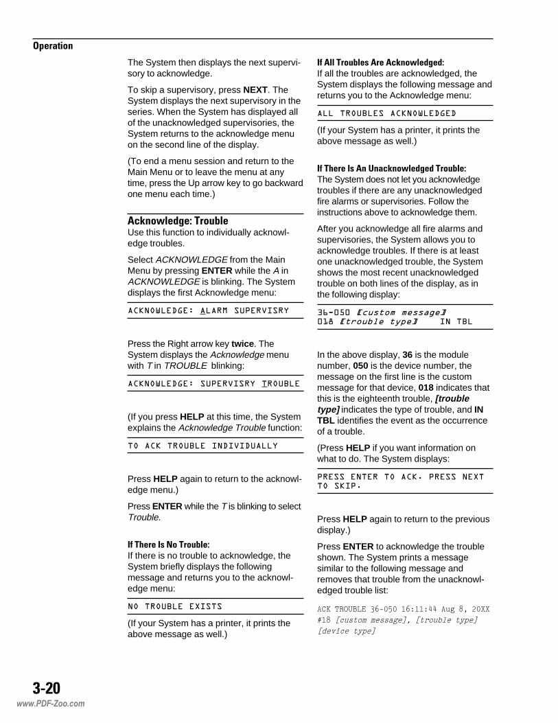
���:
���������
The System then displays the next supervi-sory to acknowledge.
To skip a supervisory, press NEXT. TheSystem displays the next supervisory in theseries. When the System has displayed allof the unacknowledged supervisories, theSystem returns to the acknowledge menuon the second line of the display.
(To end a menu session and return to theMain Menu or to leave the menu at anytime, press the Up arrow key to go backwardone menu each time.)
�*8��7 ��"�>����( �Use this function to individually acknowl-edge troubles.
Select ACKNOWLEDGE from the MainMenu by pressing ENTER while the A inACKNOWLEDGE is blinking. The Systemdisplays the first Acknowledge menu:
���5�.6�+������(��)����
Press the Right arrow key twice. TheSystem displays the Acknowledge menuwith T in TROUBLE blinking:
���5�.6�+���(��)�����������
(If you press HELP at this time, the Systemexplains the Acknowledge Trouble function:
��� �����������.�)�.��
Press HELP again to return to the acknowl-edge menu.)
Press ENTER while the T is blinking to selectTrouble.
3�0����������( �>If there is no trouble to acknowledge, theSystem briefly displays the followingmessage and returns you to the acknowl-edge menu:
�����������2����
(If your System has a printer, it prints theabove message as well.)
3� ����( ������*8��7 ��"��>If all the troubles are acknowledged, theSystem displays the following message andreturns you to the Acknowledge menu:
��������� ���5�.6�.
(If your System has a printer, it prints theabove message as well.)
3�0���������*8��7 ��"������( �>The System does not let you acknowledgetroubles if there are any unacknowledgedfire alarms or supervisories. Follow theinstructions above to acknowledge them.
After you acknowledge all fire alarms andsupervisories, the System allows you toacknowledge troubles. If there is at leastone unacknowledged trouble, the Systemshows the most recent unacknowledgedtrouble on both lines of the display, as inthe following display:
/C4�,������������ ��*8�����������������������
In the above display, 36 is the modulenumber, 050 is the device number, themessage on the first line is the custommessage for that device, 018 indicates thatthis is the eighteenth trouble, [troubletype] indicates the type of trouble, and INTBL identifies the event as the occurrenceof a trouble.
(Press HELP if you want information onwhat to do. The System displays:
(�������������� �7�(�������2�������(7
Press HELP again to return to the previousdisplay.)
Press ENTER to acknowledge the troubleshown. The System prints a messagesimilar to the following message andremoves that trouble from the unacknowl-edged trouble list:
������$ %�"�-=)�*��(=�((�77����9������
.(9�������������� �������������
����������
www.PDF-Zoo.com

����
���������
In the above message, the time and dateare the time and date that the condition wasacknowledged and 36-050 is the address.
The System then displays the next troubleto acknowledge.
When the System has displayed all of theunacknowledged troubles, it returns to theAcknowledge menu.
(To end a menu session and return to theMain Menu or to leave the menu at any time,press the Up arrow key to go backward onemenu each time.)
�*8��7 ��"�>��*�����Use this function to individually acknowl-edge security conditions.
Select ACKNOWLEDGE from the MainMenu by pressing ENTER while the A inACKNOWLEDGE is blinking. The Systemdisplays the first Acknowledge menu:
���5�.6�+������(��)����
Press the Right arrow key three times. TheSystem displays the second Acknowledgemenu, with the S in SECURITY blinking:
���5�.6�+���������� �����
(If you press HELP at this time, the Systemexplains the Acknowledge Security function:
��� ���� ��������.�)�.��
Press HELP again to return to the Acknowl-edge menu.)
Press ENTER while the S is blinking toselect Security.
3�0��������*�����������������*8��7 ��"�>If there is no Security condition to acknowl-edge, the System briefly displays thefollowing message and then returns you tothe Acknowledge menu:
����� �������2����
(If your System has a printer, it prints theabove message as well.)
3� ��*�������������������*8��7 ��"��>If all security conditions are acknowledged,the System displays the following messageand returns you to the Acknowledge menu:
��� ����������� ���5�.6�.
(If your System has a printer, it prints theabove message as well.)
3�0���������*8��7 ��"����*��������������>The System does not let you acknowledgesecurity conditions if there are any unac-knowledged alarms, supervisories, ortroubles.
If there is at least one unacknowledgedalarm, the System briefly displays thefollowing message and then returns you tothe Acknowledge menu:
��������� ���5�.6�.����
(If your System has a printer, it prints theabove message as well.)
Follow the instructions above to acknowl-edge any unacknowledged alarms,supervisories, and troubles.
After you acknowledge all fire alarms,supervisories, and troubles, the Systemallows you to acknowledge security condi-tions. If there is at least one unacknowledgedsecurity condition, the System displays themost recent unacknowledged securitycondition:
A14�,8����������� ���,������������������������
In the above display, 42 is the modulenumber, 058 is the device number, themessage on the first line is the custommessage for the device at that location, 005indicates that this is the fifth securitycondition, [device type] indicates the typeof device causing the security condition, andIN SEC identifies this as an off-normalsecurity condition.
(Press HELP if you want information onwhat to do. The System displays:
(�������������� �7�(�������2�������(7
Press HELP again to return to the previousdisplay.)
www.PDF-Zoo.com

����
���������
Press ENTER to acknowledge the securitycondition shown. The System prints amessage similar to the following messageand removes that security condition fromthe unacknowledged security list:
���� ������A14�,8�*C+**+AA�"3�801�229,����������� ���������������
In the above message, the time and dategiven are the time and date when thesecurity condition was acknowledged, and42-058 is the address.
The System then displays the next securityreport to acknowledge.
To skip a security condition, press NEXT.The System displays the next securitycondition in the series. When the Systemhas displayed all of the unacknowledgedsecurity conditions, it returns to the Ac-knowledge menu.
(To end a menu session and return to theMain Menu or to leave the menu at any time,press the Up arrow key to go backward onemenu each time.)
!������The List menu has eighteen items fromwhich to choose; the shortened terms usedin the menu are in parentheses.
You can generate a printed list or report forevery item on the List menu except NodeAddress. See the discussion for each itemthat follows.
Status
Alarm
Supervisory (Supervsry)
Trouble
Security
Sensitivity (Senstvty)
Voltages
Temp
Module type (Mod type)
Device type (Dev type)
Message
Software version (SW version)
Output states
Device usages
Node address
Analaser
Percent/ft
ASD_apps
Use the List menu to learn the followinginformation:
• Status of the System
• Alarm information
• Supervisory information
• Trouble information
• Security information
• Detector sensitivity
• Detector voltageAnalogThreshold (Thresh)Sensitivity (Sens)
• Temperature of FP-11 or FPT-11
• Type of module
• Type of device
• Custom message of the givenaddress
• Version of the System software
• Output states
• Device usages
• Panel's X-Network node address
• Percent per foot obscurationSensitivityPre-alarmAnalog
• Device application (ASD setting)
4������"�0�!�������From the Main Menu, use the Left or Rightarrow key to cause the L in List to blink.
If you press HELP at this point, the Systemexplains the List function:
�������������0�.�)� �0� �6����:�
Press HELP again to return to the MainMenu.
www.PDF-Zoo.com

����
���������
Press ENTER to select LIST. The Systemdisplays the first List menu, with the S inSTATUS blinking:
���+������������(��)���
(To end a menu session and return to theMain Menu or to leave the menu at anytime, press the Up arrow key to go back-ward one menu each time.)
!���>������The List Status function shows you thenumber of acknowledged and unacknowl-edged alarms, supervisories, troubles, andsecurity conditions, in that order.
From the List menu, use the Right or Leftarrow keys to cause the S in STATUS toblink.
(If you press HELP at this point, the Systemexplains the List Status function:
�<�5���������:� ��.�;��� ��.
Press HELP again to return to the Listmenu.)
When you press ENTER to select ListStatus, the display first shows the totalnumber of alarms and the number ofacknowledged alarms:
1�������1���� �
To view, in order, the status ofsupervisories, troubles, and securityconditions, press NEXT.
After the Security display, the Systemreturns to the List menu.
To make a printed list of current status,press PRINT when the S in STATUS isblinking. The System will print a listingsimilar to the following:
����� �����������((�����=������(�������
������������������������� !"�#
����� !"�#����
-����$ %�"��-����$ %�"����
�����"� �&�'����"� �&�'����
In the above printed message, there aretwo alarms, both of them acknowledged, nosupervisory conditions, 30 trouble condi-tions, all acknowledged, and no securityconditions.
(To end a menu session and return to theMain Menu or to leave the menu at any time,press the Up arrow key to go backward onemenu each time.)
!���>� ���The List Alarm function shows you all thefire alarms currently in the System in theorder they occurred.
From the List menu, use the Left or Rightarrow key to cause the A in ALARM tobegin blinking.
If you press HELP at this point, the Systemexplains the List Alarm function:
�<�5���.�)�.����������
Press HELP again to return to the Listmenu.
Press ENTER to select ALARM and displayalarm information on the MKB-4 display.
3�0����������� ���>If there is no fire alarm, the System brieflydisplays the following message and thenreturns you to the List menu:
�������2����
3�0���������� ���>If there is at least one fire alarm, the Systemshows the most recent alarm, alternatingbetween the following two displays:
*4��*����������� ���1��������������������
*4��*����������� ���1����������� ����
Press NEXT to show the two displays for theprevious alarm in the sequence. (PressingHOLD freezes a display for as long as youkeep HOLD depressed.)
www.PDF-Zoo.com

���#
���������
When the System has shown all current firealarms, it returns to the List menu.
To obtain a full printed list of alarms inthe following format—one item for eachcurrent alarm—press PRINT when the A inALARM is blinking.
�������1?��������� ����(7�-*����$0���+������
������()*�(7�-7����$0���+������.(
������������� �����������
In the above listing, 1-5 is the address ofthe device in alarm, the time is the time thedevice went into alarm, #1 is the number ofthis alarm in the current list, [custommessage] is the custom message for thedevice in alarm, and [device type] is thetype of device in alarm.
(To end a menu session and return to theMain Menu or to leave the menu at any time,press the Up arrow key to go backward onemenu each time.)
!���>�����%�����The List Supervisory function shows you allthe supervisories currently in the System inthe order they occurred.
From the List menu, use the Left or Rightarrow key to cause the S in SUPERVSRYto blink.
(If you press HELP at this point, the Systemexplains the List Supervisory function:
�<�5���.�)�.����(��)�����
Press HELP again to return to the Listmenu.)
Press ENTER to select SUPERVSRY anddisplay supervisory information on theMKB-4 display.
3�0�����������%�����>If there is no supervisory, the System brieflydisplays the following message and thenreturns you to the List menu:
�����(��)�������2����
3�0����������%�����>If there is at least one supervisory, theSystem shows the most recent supervisory,
alternating between the following twodisplays:
*4��*����������� ���1������������� �����(
*4��*����������� ���1����������� �����(
Press NEXT to show the two displays for theprevious supervisory in the sequence.(Pressing HOLD freezes a display for aslong as you keep HOLD depressed.)
When the System has shown all currentsupervisories, it returns to the List menu.
To obtain a full printed list ofsupervisories in the following format—oneitem for each current supervisory—pressPRINT when the S in SUPERVISORY isblinking.
�������1?���������3�������(7�-*����$0���+������
� !"�#�&4�-�)7*�(7�-7����$0���+������
.>�������������� �����������
In the preceding listing, 32-45 is the ad-dress of the device in supervisory, #7 is thenumber of the supervisory in the current list,[custom message] is the custom messagefor the device in supervisory, and [devicetype] is the type of device in supervisory.
(To end a menu session and return to theMain Menu or to leave the menu at any time,press the Up arrow key to go backward onemenu each time.)
!���>����( �The List Trouble function shows you all thetroubles currently in the System in the orderthey occurred.
From the List menu, use the left or rightarrow key three times to cause the T inTROUBLE to blink.
(If you press HELP at this point, the Systemexplains the List Trouble function:
�<�5���.�)�.��������������
Press HELP again to return to the Listmenu.)
www.PDF-Zoo.com

���2
���������
Press ENTER to select TROUBLE anddisplay trouble information on the MKB-4display.
3�0����������( �>If there is no trouble, the System brieflydisplays the following message and thenreturns to the List menu:
�����������2����7
3�0���������( �>If there is at least one trouble, the Systemshows the most recent trouble, alternatingbetween the following two displays:
*4��*����������� ���1�������������� �����
*4��*���������������1����������� �����
Press NEXT to show the two displays for theprevious trouble in the sequence. (PressingHOLD freezes a display for as long as youkeep HOLD depressed.)
When the System has shown all currenttroubles, it returns to the List menu.
To obtain a full printed list of troubles inthe following format—one item for eachcurrent trouble—press PRINT when the Tin TROUBLE is blinking.
�������1?�������1�:������(7�-*����$0���+�������
��$ %�"�&4��+)7(�(7�-7����$0���+������
.>�������������� ������������
����������
In the above listing 29-41 is the address ofthe device in trouble, the time tells when thedevice went into trouble, #7 is the numberof this trouble in the current list, [custommessage] is the custom message for thedevice in trouble, [trouble type] is the typeof trouble, and [device type] is the type ofdevice in trouble.
(To end a menu session and return to theMain Menu or to leave the menu at any time,press the Up arrow key to go backward onemenu each time.)
!�����*���������������The List Security function shows you all thesecurity conditions currently in the System inthe order they occurred.
From the List menu, use the left or rightarrow key to cause the S in SECURITY toblink.
(If you press HELP at this point, the Systemexplains the List Security function:
�<�5���.�)�.���� �����������
Press HELP again to return to the Listmenu.)
Press ENTER to select SECURITY anddisplay security information on the MKB-4display.
3�0��������*��������������>If there is no security condition, the Systembriefly displays the following message andthen returns you to the List menu:
����� �������2����
3�0�������*��������������>If there is at least one security condition,the System shows the most recent securitycondition, alternating between the followingtwo displays:
*4��*����������� ���1������������� �����
*4��*����������� ���1����������� �����
Press NEXT to show the two displays for theprevious security condition in the sequence.(Pressing HOLD freezes a display for aslong as you keep HOLD depressed.)
When the System has shown all currentsecurity conditions, it returns to the Listmenu.
To obtain a full printed list of securityconditions in the following format— oneitem for each current security condition—press PRINT when the S in SECURITY isblinking.
www.PDF-Zoo.com

���-
���������
�������1?�������0���������(7�-*����$0���+������
�"� ��'�&4��+)7��(7�-7����$0���+�����
��.>�������������� �����������
In the above listing 29-42 is the address ofthe device causing the security condition, thetime when the device caused the securitycondition, #7 is the number of this securitycondition, [custom message] is the custommessage for the device causing the securitycondition, and [device type] is the type ofdevice causing the security condition.
To end a menu session and return to theMain Menu or to leave the menu at any time,press the Up arrow key to go backward onemenu each time.
!���>�������%���������"�Use List Sensitivity to show sensitivitysetting of individual smoke detectors onanalog loops.
From the List menu use the left or rightarrow key to cause the S in SENSTVTY tostart blinking:
���+���������� �����������)��
(If you press HELP at this point, the Systemdisplays:
�<�5�.��� �����������)�����
Note that List Sensitivity shows the sensitiv-ity of smoke detectors only. Press HELPagain to return to the List menu.)
���� ���0��������%���������"�3�����%�*�Press ENTER to select List Sensitivity. TheSystem asks you for a module and devicenumber.
��(�������.���;�.�)� �+���*4��*
Type the three-digit module number andthree-digit device number using the nu-meric keypad and press ENTER. (Enter allleading zeros.)
The System displays the sensitivity settingof the device specified (Hi_3, Hi_2, Hi_1,Norm, Low_1, Low_2 or Low_3 ).
Press NEXT to display the address andsensitivity setting of each succeedingsmoke detector. When the System hasshown the sensitivity settings of all smokedetectors on that analog loop, it returns tothe List menu.
To leave the List Sensitivity menu withoutgoing through the entire analog loop, pressthe Up arrow key. The System displays theList menu.
1�����0��������%���������"�3� ���8�����*��������"���������*�3������� �Press PRINT when the S in SENSTVTY isblinking. The System then asks for amodule number.
��(�������.���������+���������������
Type the three-digit module number andpress ENTER. (Enter all leading zeros.)
The System prints the sensitivity settings(Hi_3, Hi_2, Hi_1, Norm, Low_1, Low_2 orLow_3, or ... if there is no smoke detector) ofall the devices assigned to the analog loop.
�������3������?1�� 1�����(
() @&A- �) ��� -) 4$�� 7) ��� *) ���
=) ��� >) ��� 9) ��� +) ��� (�) ���
(() 4$�� (�) ��� (-) ��� (7) ��� (*) �$5(
NOTE: You cannot print the sensitivitysetting of a single smoke detector.
(To end a menu session and return to theMain Menu or to leave the menu at any time,press the Up arrow key to go backward onemenu each time.)
!���>,� ��"��Use List Voltages to show the voltages ofinitiating devices on analog loops.
From the List menu press the Left or Rightarrow key to cause the V in VOLTAGES tostart blinking:
���+��� �����0������)��0�)��6��
www.PDF-Zoo.com

���+
���������
(If you press HELP at this point, the Systemdisplays:
�<�5�.��� ����)��6��
Press HELP again to return to the List menu.)
���� ���0�,� ��"��3�����%�*�Press ENTER to select List Voltages. TheSystem asks you for a module number anddevice number. Type the three-digit modulenumber and three-digit device numberusing the numeric keypad and pressENTER. (Enter all leading zeros.) TheSystem shows the following menu for thatdevice (the A in ANALOG will be blinking):
��*4��*���6��<���<�����
Press ENTER to show the Analog voltagefor that device. When you ask for anyvoltage, the System displays Please wait forresponse until it receives a reading fromthe device; if you have just reset theSystem, it alternates the above messagewith the message Device being initialized.The display for Analog voltage is similar tothe following (readings are dynamic):
��*4��*���61�'�17B,�)���
Press ENTER to return to the previousdisplay. To view the Threshold or Sensitivityvoltage of any device listed, use the Rightand Left arrow keys to highlight the firstletter of the category desired and pressENTER.
The display for Threshold voltage is similarto the following:
��*4��*��<���<�.�'�A7B,�)���
The display for Sensitivity voltage is similarto the following (readings are dynamic):
��*4��*��������)����'�17C1�)���
Press the Up arrow key to return to the List:Voltage Mod_type Dev_type menu.
If the module number entered is not ananalog loop, the System displays:
��������� ������
If the device address has no device as-signed by CSG-M, the System displays:
������������ ���7
When displaying sensitivities, if the device isnot a smoke detector, the System displays:
��������������������7
1�����0�,� ��"��3� ��%�*������"���������*�3������� �Press PRINT when the V in Voltages isblinking. The System asks you for a modulenumber. Type the three-digit module numberand press ENTER. (Enter all leadingzeros.)
��14��*�!�$�3��D���D���!�
Press ENTER to print the Analog voltagefor all devices assigned to the module(ND = No Device).
�4��$6�#$���6"��B$���$, �"�(
() ���� �) ���� -) 4, 7) 4, *) 4,
=) 4, >) 4, 9) 4, +) 4, (�) 4,
(() 4, (�) 4, (-) 4, (7) 4, (*) 4,
To print the Threshold voltages of all thedevices for the specified module, use thearrow keys to cause the T in THRESH toblink and press PRINT. The System printsthose threshold voltages in a format similar tothe following (ND = No Device):
�@�"�@$�,�#$���6"��B$���$, �"�(
() 7�>* �) 7�>* -) 4, 7) 4, *) 4,
=) 4, >) 4, (�) 4, 9) 4, +) 4,
(() 4, (�) 4, (-) 4, (7) 4, (*) 4,
www.PDF-Zoo.com

���;
���������
To print the Sensitivity voltages of all thesmoke detectors for the specified module,use the arrow keys to cause the S in SENSto blink and press PRINT. The Systemprints those sensitivity voltages in a formatsimilar to the following (ND = No Device, ordevice not a smoke detector):
�"4�&�&#&�'�#$���6"��B$���$, �"�(
() ��>* �) ��=� -) 4, 7) 4, *) 4,
=) 4, >) 4, (�) 4, 9) 4, +) 4,
(() 4, (�) 4, (-) 4, (7) 4, (*) 4,
(To end a menu session and return to theMain Menu or to leave the menu at any time,press the Up arrow key to go backward onemenu each time.)
!���>����Use List Temp to display the currenttemperature on the LCD display at thelocation where the detector is installed.
From the List menu use the left or rightarrow key to cause the T in Temp to startblinking:
���+����(
Press ENTER to select List Temp. TheSystem asks you for a module and devicenumber:
������!����"$��;�.��� �+
Type the three-digit module number andthree-digit device number using the nu-meric keypad and press ENTER.
If the device is not installed or is not anFP-11 or FPT-11, the system displaysfollowing message:
������$� �#$��������.��� �+
If the device is an FP-11 or FPT-11, thetemperature is displayed in the followingformat:
��*4��*�������1,�.�6� �&�BB�.�6�:
Press NEXT to display the temperature ofthe FP-11 or FPT-11 at the next higheraddress in the same loop.
To leave the Temp menu without goingthrough all subaddresses, press the Uparrow key. The System displays the Listmenu.
!���>���� �����Use the List Mod_type to show the type ofa particular module.
From the List menu use the Left or Rightarrow key to cause the M in MOD TYPE tostart blinking:
���+�)��6�����.���(�������)��
(If you press HELP at this point, the Systemexplains this function:
�<�5��<����(���:���.��
Press HELP again to return to the Listmenu.)
���� ���0����� ������3������� �Press ENTER when the M in MOD_ TYPEis blinking. The System asks you for amodule number:
��(�������.���������+
Type the three-digit module number usingthe numeric keypad and press ENTER.(Enter the leading zeros.) The Systemdisplays the module type for the modulenumber specified:
��.��BA���(�+� E�A
If you press NEXT, the System displays themodule type for the next module number inthe sequence:
��.��B,���(�+�.
NOTE: If you enter a module number notassigned in CSG-M, the Systemdisplays:
�����.����6��.
With each press of NEXT, the Systemcontinues to display module types through
www.PDF-Zoo.com

���<
���������
number 255, the highest module numberallowed by the System. It then returns tothe List menu.
1�����0����� �����������7��8��������3� ���� ��Press PRINT when the M in MOD_ TYPE isblinking to print a full list of module typesand their Network addresses. The Systemprints a list similar to the following:
�������1?��1����������
() #>���, �) #>���,
-) #7��C�)7
�*() #*���%)7 �*-) #(����)&D�!����
In the above display, the number followingthe V (for example, V7) is the softwareversion number of the software installed inthe module.
(To end a menu session and return to theMain Menu or to leave the menu at any time,press the Up arrow key to go backward onemenu each time.)
!���>��%�*�����Use List Device Type to show the type of aparticular device.
From the List menu use the Left or Rightarrow key to cause the D in DEV_TYPE tostart blinking:
���+�)��6�����.���(��.�)���(�
(If you press HELP at this point, the Systemdisplays:
�<�5��<����(���:�.�)� �
Press HELP again to return to the List menu.)
���� ���0���%�*������3����*�3�����%�*�Press ENTER when the D is blinking toselect LIST DEV_TYPE.
The System asks you for a module anddevice number:
��(�������.���;�.�)� �+
Type the three-digit module number andthree-digit device number using the nu-
meric keypad and press ENTER. (Enter allleading zeros.) The System displays thedevice type for the address specified:
��A4��*���(�+�������������
If you press NEXT, the System displays thedevice type for the next device in thesequence:
��A4��1���(�+�������������
With each press of NEXT, the Systemcontinues to display device types until thereare no more devices for that module. TheSystem then returns to the List menu. Toproceed to another module, follow thepreceding instructions.
1�����!����3��%�*������"���������*�3������� �Press PRINT when the D is blinking toselect LIST DEVICE. The System asks youfor a module number:
��(�������.���������+
Type only the module number and pressPRINT. (Enter all leading zeros.) TheSystem prints a list of all device typesassigned to the specified module in aformat similar to the following:
�������1?�,�3�0��������1�����(�E��,F�
�()��&)=�,�,�����<��0��&���
��)��&)=�,�,�����<��0��&���
�7)��&)=�,��<��0�������G������
�*)��&)=���<��0��&���
�>)��&)=���<��0��&���
�(�)&,)=��)(-*����� ���,���0�1�
(()&,)=��)(-*����� ���,���0�1�
�(*)&,)=�&�&1��H���1��,���0�1�
(=)&,)=�&�&1��H���1��,���0�1�
(To end a menu session and return to theMain Menu or to leave the menu at any time,press the Up arrow key to go backward onemenu each time.)
!���>�����"�Use List Message to show the CSG-Massigned custom message of a particulardevice.
www.PDF-Zoo.com

���:
���������
From the List menu use the Left or Rightarrow key to cause the M in MESSAGE tostart blinking:
���+���.���(��.�)���(������6�
(If you press HELP at this point, the Systemdisplays:
�<�5�����6��:����.�)� �
Press HELP again to return to the previousdisplay.)
���� ���0���%�*������"��3����*�3�����%�*�Press ENTER when the M in MESSAGE isblinking to select List Message.
The System asks you for a module anddevice number:
��(�������.���;�.�)� �+
Type the three-digit module number andthree-digit device number using the nu-meric keypad and press ENTER. TheSystem displays the message for theaddress specified:
�C-4��*����������� �
If you press NEXT, the System displays themessage for the next device number in thesequence:
�C-4��1����������� �
With each press of NEXT, the Systemcontinues to display device messages untilthere are no more devices for that module.
To proceed to another module, follow thepreceding instructions.
1�����!����3�����������"��3������*�3������� �Press PRINT when the M in MESSAGE isblinking to select List Message. TheSystem asks you for a module number:
��(�������.���������+
Type only the module number and pressPRINT. (Enter all leading zeros.) TheSystem prints a list of all the custom devicemessages for the specified module in aformat similar to the following:
�������1?�������������1�����(�E��,F�
���7)�1�?�� *)��?������
���=)"I�0��$??��(������>)� ����
���9)"I�0��$??���������+)�� �����
��(�)"I�0��$??��-�����(()�1�?���
(To end a menu session and return to theMain Menu or to leave the menu at anytime, press the Up arrow key to go back-ward one menu each time.)
!���>��3�7���,������Use List Software Version to show:
1. System Custom Message2. MXL-IQ Software Version3. Version of CSG-M used to Create the
System4. CSG-M File Name Installed5. Date and Time of Installation
From the List menu use the Left or Rightarrow key to cause the S in S/W_VERSIONto start blinking:
���+��&5�)������������
(If you press HELP at this point, the Systemdisplays:
�<�5���:�5���)������
Press HELP again to return to the previousdisplay.)
���� ���0���3�7���,�������3?�����������3�7���Press ENTER when the S is blinking toselect List S/W_VERSION.
The System displays the CSG-M assignedSystem custom message:
��6���������������� �
Press NEXT again to display the MXL-IQsoftware version:
�24�F�)������+���������������
www.PDF-Zoo.com

����
���������
Press NEXT again to display the version ofCSG-M used to create this System.
�6�)������+���������������
Press NEXT again to display the CSG-Mfile name installed.
���� �+�� ��������
Press NEXT again to display the date andtime of CSG-M installation:
�.�.+���������������
1�����0���3�7���,�������3?�����������3�7���Press PRINT when the S in SW_ VER-SION is blinking to select List S/W_Version. The System prints the SystemCustom Message, MXL-IQ SoftwareVersion, Version of CSG-M Used to Createthe System, CSG-M File Name Installed,and Date and Time of Installation:
�1?�<����#����1��&�?1� ���1����
((�-*�-�������(������
&���������1����������������������
���)&D�#����1���(���
��6�#����1���=��+
�1��0����*$����
�1������(=��+�-*�$0���*������
(To end a menu session and return to theMain Menu or to leave the menu at any time,press the Up arrow key to go backward onemenu each time.)
!���>������������Use List Output States to show the currentstates of individual outputs in the MXL-IQ.
From the List menu use the left or rightarrow key to cause the O in Output Statesto start blinking:
���+����(��������
(If you press HELP at this point, theSystem displays:
�<�5&(��������(��������
Press HELP again to return to the List menu.)
���� ���0��������������3�����%�*�Press ENTER to select List Output States.The System asks you for a module anddevice number.
��(�������.���;�.�)� �+���*4��*
Type the three-digit module number andthree-digit device number using the nu-meric keypad and press ENTER. (Enter allleading zeros.)
The System displays the output state of thedevice specified.
Press NEXT to display the address andoutput state of each succeeding device.When the System has shown the outputstates of all devices at that address, itreturns to the List menu.
To leave the List output state menu withoutgoing through all subaddresses, press theUp arrow key. The System displays the Listmenu.
1�����0���%�*�������������3��%�*������"���������*�3������� �Press PRINT when the O in Output Statesis blinking. The System then asks for amodule number.
��(�������.���������+��%��"$��!"%#���
Type the three-digit module number andpress ENTER. (Enter all leading zeros.)
The System prints the output state of all ofthe devices assigned to that module.
�������1?�$������������?1���1�����(�E��,F�
()��I�������$������$BB
�)��I�������$������$4
-)��I�������$������$4
7)��I�������$������$BB
!���>��%�*����"��Use List Device Usages to show the usesof individual devices as programmed inCSG-M.
www.PDF-Zoo.com

����
���������
From the List menu, use the left or rightarrow key to cause the D in DEV_USAGESto start blinking:
���+�.�)���6��
(If you press HELP at this point, the Systemdisplays:
�<�5&(�����.�)� ����6��
Press HELP again to return to the Listmenu.)
���� ���0����"��3�����%�*�Press ENTER to select List Dev_usages.The System asks you for a module anddevice number.
��(�������.���;�.�)� �+���*4��*
Type the three-digit module number andthree-digit device number using the nu-meric keypad and press ENTER. (Enter allleading zeros.)
The System displays the use of the devicespecified (i.e., Alarm, Trouble, or Status).
Press NEXT to display the address and useof each succeeding device. When theSystem has shown the uses of all devicesat that address, it returns to the List menu.
To leave the List Dev_usage menu withoutgoing through all subaddresses, press theUp arrow key. The System displays the Listmenu.
1�����0���%�*����"���3��%�*������"���������*�3������� �Press PRINT when the D in DEV_USAGESis blinking. The System then asks for amodule number.
��(�������.���������+��%��"$��!"%#���
Type the three-digit module number andpress ENTER. (Enter all leading zeros.)
The System prints the uses of all of thedevices assigned to that module.
�������1?�,�3�0�� �����?1�� 1�����(�E��,F
()������������)���$ %�"�����-)����� �
7)�����������*)���$ %�"�����=)�$ �! ��$4�'
!���>�����������Use List Node Address to show the panel'sX-Net node address.
From the List menu, use the left or rightarrow key to cause the N in NODE AD-DRESS to start blinking:
���+���.��..����
���� ���0������������Press ENTER to select List Node Address.The System displays the X-Net nodeaddress for that particular MXL-IQ panel.
!���>��� ����Use List ANALASER to display operationalcharacteristics of the AnaLASER devices.
Press ENTER when the A in ANALASER isblinking to select List ANALASER.
Use the Left or Right arrow to move to thefollowing selections:
����+��%�G������:$�H��������(��
(If you press HELP at this point, the Systemdisplays:
.��(��������������)�
Press HELP again to return to the Listmenu.)
!������ ���� C ���8�D!�%Press ENTER when the S in SMOKE_LEVis blinking to select List ANALASERSMOKE_LEV.
The System asks you for a module anddevice number:
��(�������.���;�.�)� �
Type the three-digit NIM-1R (ANA) modulenumber and three-digit ACC device ad-dress number using the numeric keypad
www.PDF-Zoo.com
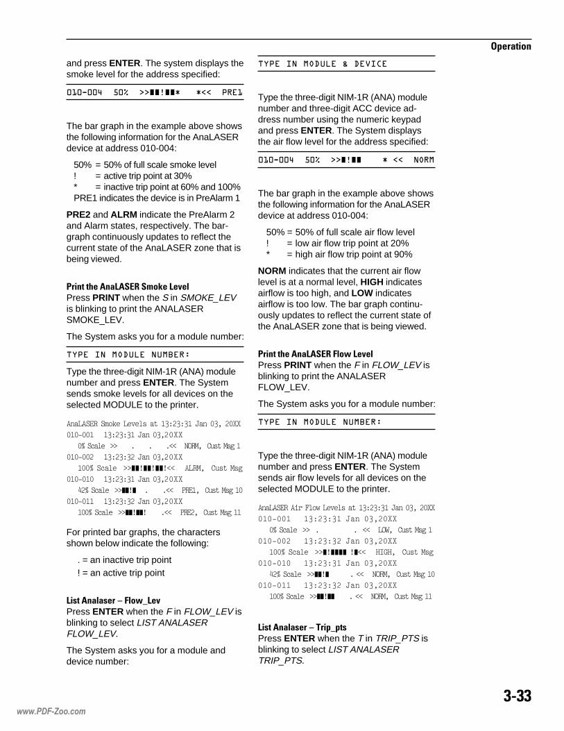
����
���������
and press ENTER. The system displays thesmoke level for the address specified:
�*�4��A��,�I��>>JJKJJL���L==��(��*
The bar graph in the example above showsthe following information for the AnaLASERdevice at address 010-004:
50% = 50% of full scale smoke level! = active trip point at 30%* = inactive trip point at 60% and 100%PRE1 indicates the device is in PreAlarm 1
PRE2 and ALRM indicate the PreAlarm 2and Alarm states, respectively. The bar-graph continuously updates to reflect thecurrent state of the AnaLASER zone that isbeing viewed.
1�����0����!��4 ���8�!�%� Press PRINT when the S in SMOKE_LEVis blinking to print the ANALASERSMOKE_LEV.
The System asks you for a module number:
��(�������.���������+
Type the three-digit NIM-1R (ANA) modulenumber and press ENTER. The Systemsends smoke levels for all devices on theselected MODULE to the printer.
������"��� 1;����3�������(-��-�-(������-������
�(�)��(���(-��-�-(������-�����
�J��0�����KK������������������LL���4$�������������(
�(�)������(-��-�-�������-�����
(��J��0�����KK M M MLL�����������������
�(�)�(����(-��-�-(������-�����
7�J��0�����KK M ����������LL���!�"(�����������(�
�(�)�((���(-��-�-�������-�����
(��J��0�����KK M M������LL���!�"������������((
For printed bar graphs, the charactersshown below indicate the following:
. = an inactive trip point! = an active trip point
!������ ���� C � �7D!�%Press ENTER when the F in FLOW_LEV isblinking to select LIST ANALASERFLOW_LEV.
The System asks you for a module anddevice number:
��(�������.���;�.�)� �
Type the three-digit NIM-1R (ANA) modulenumber and three-digit ACC device ad-dress number using the numeric keypadand press ENTER. The System displaysthe air flow level for the address specified:
�*�4��A��,�I��>>JKJJ����L�==������
The bar graph in the example above showsthe following information for the AnaLASERdevice at address 010-004:
50% = 50% of full scale air flow level! = low air flow trip point at 20%* = high air flow trip point at 90%
NORM indicates that the current air flowlevel is at a normal level, HIGH indicatesairflow is too high, and LOW indicatesairflow is too low. The bar graph continu-ously updates to reflect the current state ofthe AnaLASER zone that is being viewed.
1�����0����!��4 � �7!�%� Press PRINT when the F in FLOW_LEV isblinking to print the ANALASERFLOW_LEV.
The System asks you for a module number:
��(�������.���������+
Type the three-digit NIM-1R (ANA) modulenumber and press ENTER. The Systemsends air flow levels for all devices on theselected MODULE to the printer.
������"������B�1<���3�������(-��-�-(������-������
�(�)��(���(-��-�-(������-�����
�J��0�����KK������������������LL����$5�����������(
�(�)������(-��-�-�������-�����
(��J��0�����KK M �M LL���@&6@����������
�(�)�(����(-��-�-(������-�����
7�J��0�����KK M ���������LL���4$�������������(�
�(�)�((���(-��-�-�������-�����
(��J��0�����KK M �������LL���4$�������������((
!������ ���� C ����D���Press ENTER when the T in TRIP_PTS isblinking to select LIST ANALASERTRIP_PTS.
www.PDF-Zoo.com

���#
���������
The System prompts you to select betweenALARM_TRIP and FLOW_TRIP.
Press ENTER when the A in ALARM_TRIPis blinking to select LIST TRIP_PTSALARM_TRIP.
The System asks you for a module anddevice number.
��(�������.���;�.�)� �
Type the three-digit NIM-1R (ANA) modulenumber and three-digit ACC device ad-dress number using the numeric keypadand press ENTER. The System displaysthe current alarm trip point settings for theaddress specified:
�*�4��A��(*+��1�I����(1+��C�I�����+��-�I
1�����0����!��4 � �������1��Press PRINT when the A in ALARM_TRIPis blinking to print the ANALASERALARM_TRIP points.
The System asks you for a module number:
��(�������.���������+
Type the three-digit NIM-1R (ANA) modulenumber and press ENTER. The Systemsends alarm trip point levels for all deviceson the selected MODULE to the printer.
������"������ �����!1���������(-��-�-(�������-������
�(�)��(���(-��-�-(������-��������!�"(��(�J��!�"���-�J
������(��J�����������(
�(�)������(-��-�-(������-��������!�"(��-�J��!�"���*�J
�������+�J������������
�(�)�(����(-��-�-(������-��������!�"(��(�J��!�"���*�J
������(��J�����������(�
�(�)�((���(-��-�-(������-��������!�"(��*�J��!�"���9�J
������(��J�����������((
Press ENTER when the F in FLOW_TRIP isblinking to select LIST TRIP_PTSFLOW_TRIP.
The System asks you for a module anddevice number.
��(�������.���;�.�)� �
Type the three-digit NIM-1R (ANA) modulenumber and three-digit ACC device ad-
dress number using the numeric keypadand press ENTER. The System displaysthe current air flow trip point settings for theaddress specified:
�*�4��A���5+��1�I����<�6<+��8�I
1�����0����!��4 � �7����1��Press PRINT when the F in FLOW_TRIPis blinking to print the ANALASERFLOW_TRIP points.
The System asks you for a module number:
��(�������.���������+
Type the three-digit NIM-1R (ANA) modulenumber and press ENTER.
The System sends air flow trip point levelsfor all devices on the selected MODULE tothe printer.
������"������B�1<�����!1��������(-��-�-(������-������
�(�)��(���(-��-�-(������-���������$5��(�J��@&6@��+�J�
��������(
�(�)������(-��-�-(������-���������$5����J��@&6@��9�J�
��������(
�(�)�(����(-��-�-(������-���������$5��-�J��@&6@��>�J�
��������(
�(�)�((���(-��-�-(������-���������$5��(�J��@&6@��9�J�
��������(
!���>1��*���)3�Use List Percent/ft to show settings inpercent/ft obscuration of the ILI and ILPSeries detectors.
From the List menu, use the left or rightarrow key to cause the P in PERCENT/FTto start blinking:
���+�(�� ���&:�
Press ENTER to select List Percent/ft. TheSystem asks you for a module and devicenumber.
��(�������.���;�.�)� �+���*4��*
Type in the three-digit module number andthe three-digit device number using thenumeric keypad and press ENTER. TheSystem displays the following menu for thatdevice (the S in Senstvty will be blinking):
www.PDF-Zoo.com

���2
���������
��14��/�������)�����(��4��������6
!���1��*���)3� C �����%��The display for Sensitivity supplies thecurrent sensitivity as read back from thedetector and is similar to the following(readings are dynamic):
��14��/������*7AI&:��������
!���1��*���)3� C 1���� ���The display for Pre-alarm supplies thecurrent Pre-alarm setting read back fromthe detector and is similar to the following(readings are dynamic):
��14��/�(��4���*7AI&:��������
!���1��*���)3� C ��� �"The display for Analog supplies the currentanalog2 reading read from the detector andis similar to the following (readings aredynamic):
��14��/������*7AI&:��������
To leave the Percent/ft menu without goingthrough all subaddresses, press the Uparrow key. The System displays the Listmenu.
1�����0���� �"!���B�������� �����"���1��*���)3��(�*�������Press PRINT when the P in Percent/ft isblinking. The System asks you for a modulenumber.
��(�������.���������+
Type the three-digit module number usingthe numeric keypad and press ENTER. TheSystem shows the following menu for thatdevice (the S in Senstvty will be blinking):
��*4��*������)����(��4������6
The System prints either the Sensitivity, Pre-alarm, or Analog of all the devices for thespecified module in a format similar to thefollowing (NA = ID-60 detector):
J8?���"4�&�&#&�&"��B$���$, �"��
()-��� �)4� -)(�7 7)-�( *)(�7
=)(�7 >)4, 9)4, +)4, (�)4,
(()4, (�)4, (-)4, (7)4, (*)4,
(=)4, (>)4, (9)4, (+)4, ��)4,
�()4, ��)4, �-)4, �7)4, �*)4,
�=)4, �>)4, �9)4, �+)4, -�)4,
-()4, -�)4, --)4, -7)4, -*)4,
-=)4, ->)4, -9)4, -+)4, 7�)4,
7()4, 7�)4, 7-)4, 77)4, 7*)4,
7=)4, 7>)4, 79)4, 7+)4, *�)4,
*()4, *�)4, *-)4, *7)4, **)4,
*=)4, *>)4, *9)4, *+)4, =�)4,
!���>���D����Use List ASD_apps to display operationalcharacteristics of the ASD devices.
From the List menu use the left or rightarrow key to cause the A in ASD_Apps tostart blinking:
���+��.�((�
���� ���0����������� �0���*�������*��3�����%�*�Press ENTER to select ASD_apps. TheSystem asks you for a module and devicenumber:
��(�������.���;�.�)� �+
Type the three-digit module number andthree-digit device number using the nu-meric keypad and press ENTER. (Enter allleading zeros.)
The System displays the currently assignedapplication for the device specified. (Refer tothe ASD Submenu Abbreviations on page I-1.)
Press NEXT to display the address andassigned application of each succeedingdevice. The System will exit the ASD_Appsmenu if there are no more ASD devices inthat module.
To leave the List ASD_Apps menu at anytime, press the Up arrow key. The Systemdisplays the List menu.
www.PDF-Zoo.com

���-
���������
��������0����������� *0���*�������*��3�0������%�*������"��������!�!���Press PRINT when the A in ASD_Apps isblinking. The System asks you for a modulenumber:
��(�������.���������+
Type the three-digit module number usingthe numeric keypad and press ENTER.(Enter all leading zeros.) The System printsa list of all the applications currently as-signed to all the ASD devices in that ALDloop in a format similar to the following (ND= No Device):
()4$4" �)!��� -)4, 7)4, *)4,
=)4, >)4, 9)4, +)4, (�)4,
(()4, (�)4, (-)4, (7)4, (*)4,
(=)4, (>)4, (9)4, (+)4, ��)4,
�()4, ��)4, �-)4, �7)4, �*)4,
�=)4, �>)4, �9)4, �+)4, -�)4,
-()4, -�)4, --)4, -7)4, -*)4,
-=)4, ->)4, -9)4, -+)4, 7�)4,
7()4, 7�)4, 7-)4, 77)4, 7*)4,
7=)4, 7>)4, 79)4, 7+)4, *�)4,
*()4, *�)4, *-)4, *7)4, **)4,
*=)4, *>)4, *9)4, *+)4, =�)4,
���� �!����The Control menu has nine items fromwhich to choose; six of the items havesubmenus, as follows (the shortened termsused in the menu are in parentheses):
Reset
Sensitivity (Senstvty)
Hi_3
Hi_2
Hi_1
Norm
Low_1
Low_2
Low_3
Arm/Disarm (Arm/dis)
Arm
Disarm
Output_on/off
Arm
Disarm
Energize
De_energize
Loop arm/disarm
arm
disarm
Net_link_request
AnalazerAlarm-tripFlow-trip
Percent/ftSensitivity(Senstvty)Pre-alarm
Change-apps
Use the Control menu to perform thefollowing functions:
• Reset the System
• Change the sensitivity of a smokedetector
• Arm or disarm an initiating device
• Arm an output device
• Disarm and energize an output device
• Disarm and de-energize an outputdevice
• Arm and disarm a loop
• Send a request to the NetworkCommand Center (NCC) to disconnectthe MXL from the network
• Change AnaLASER Alarm Trip pointsand Flow Trip points
• Change sensitivity and pre-alarmsettings in percent/ft obscuration of theILI and ILP detectors
• Change the application of an ASD device
www.PDF-Zoo.com
���+
���������
4������"�0������� ����From the Main Menu, use the arrow keys tocause the C in CONTROL to blink.
(If you press HELP at this point, the Systemexplains the Control function:
�����.�:��.��:����(������
Press HELP again to return to the MainMenu.)
Press ENTER to select CONTROL.
The System asks you for a passwordbefore it allows you to use the Controlfunctions. Enter your one- to five-digitpassword, using the numeric keypad, andpress ENTER (See the discussion underEntering Your Password on page 3-17).
If the System accepts your password, itdisplays the first Control menu, with the R inRESET blinking:
�����+������������)�����&.��
(To end a menu session and return to theMain Menu or to leave the menu at any time,press the Up arrow key to go backward onemenu each time.)
������ > ����Use Control Reset to initiate a system resetat any time.
From the Control menu, use the Left orRight arrow key to cause the R in RESET tostart blinking:
�����+������������)�����&.��
(If you press HELP while the R in RESET isblinking, the System explains this function:
������������
Press HELP again to return to the abovemenu.)
Press ENTER to reset the System anddisplay the following message:
������������
If the System is normal, when SYSTEMRESET is selected, the System displaysthe following:
���������.������
(To end a menu session and return to theMain Menu or to leave the menu at any time,press the Up arrow key to go backward onemenu each time.)
������ >�������%���Use Control Sensitivity to change thesensitivity settings of smoke detectors onanalog loops.
From the Control menu, press the Right orLeft arrow key to cause the S in SENSTVTYto start blinking:
�����+������������)�����&.��
(If you press HELP at this point, the Systemdisplays:
<�6���������)���
Press HELP again to return to the abovemenu.)
Note that Control Sensitivity allows you tochange the sensitivity settings of smokedetectors only; if you attempt to change thesensitivity setting of another type of device,the System displays:
���*4��*������������.��� ���
If you enter any address for which there isno device assigned, the System displays:
���.�)� �����6��.
Press ENTER while the S in SENSTVTY isblinking to select CONTROL SENSTVTY.
The System asks you for a module numberand device number:
��(�������.���;�.�)� �+
www.PDF-Zoo.com

���;
���������
Type the three-digit module number andthree-digit device number using the nu-meric keypad and press ENTER. TheSystem shows the following display:
��*4��*����%�<��*�<��1�<��/
The current sensitivity setting is highlighted.The System offers you a choice of sevenlevels of sensitivity: Hi_3, Hi_2, Hi_1, Norm,Low_1, Low_2 or Low_3. Use the Right andLeft arrow keys to highlight the level youwish to set for the smoke detector specifiedand press ENTER. The System makes thechange in sensitivity setting.
Press NEXT to move through the devicesuntil you display the ones you want tochange, and follow the instructions above formaking the changes.
When the System has displayed thehighest numbered device for the modulespecified, it returns to the Control menu.You can select another address by select-ing SENSTVTY and following the instruc-tions above.
To leave the Control Sensitivity displayswithout going through the entire list, pressthe Up arrow key. The System displays theControl menu.
(To end a menu session and return to theMain Menu or to leave the menu at any time,press the Up arrow key to go backward onemenu each time.)
������ >���)���Use Control Arm/dis to enable or disablethe operation of an initiating device.
From the Control menu, press the Left orRight arrow key to cause the A in ARM/DISto start blinking.
(If you press HELP at this point, the Systemdisplays:
.�����������.�)� ��
Press HELP again to return to the Controlmenu.)
Press ENTER while the A in ARM/DIS isblinking to select Control Arm/dis.
The System asks you for the modulenumber and device number of the detectoryou wish to arm or disarm. Type the three-digit module number and three-digit devicenumber using the numeric keypad andpress ENTER. (Enter all leading zeros.)The System displays:
��*4��*����.����
The System offers you a choice of armingor disarming the device. Use the Right andLeft arrow keys to highlight your choice andpress ENTER. The System makes thechange.
When you disarm an input device, theSystem automatically annunciates thedisarming as a Trouble and lights thePARTIAL SYSTEM DISABLE LED.
Press NEXT to move through the devicesuntil you display the ones you want tochange; follow the instructions above formaking the changes.
When the System has displayed thehighest numbered device for the modulespecified, it returns to the Control menu. Toarm or disarm another module device,select ARM/DIS and follow the precedinginstructions.
(To end a menu session and return to theMain Menu or to leave the menu at any time,press the Up arrow key to go backward onemenu each time.)
������ >��������)�33Use Control Output_On/Off to arm ordisarm an output device. In addition, you canenergize or de-energize disarmed outputdevices.
From the Control menu, press the Left orRight arrow key to cause the O in OUTPUTto start blinking:
��������&.������(��M��&�::
(If you press HELP at this point, the Systemdisplays:
��������(�����������::
www.PDF-Zoo.com

���<
���������
Press HELP again to return to the abovemenu.)
Press ENTER while the O in OUTPUT isblinking to select CONTROL_OUTPUT ON/OFF.
The System asks for a module number anddevice number of the device you wish to turnon or off (energize or de-energize). Typethe three-digit module number and three-digit device number using the numerickeypad and press ENTER. (Enter allleading zeros.)
The System shows the following display:
1,/4��,����.����
The System offers you a choice of armingor disarming the device.
Use the Right and Left arrow keys tohighlight your choice and press ENTER.
If you have armed the device, you canpress NEXT to display the number of thenext device in the sequence. You can alsopress the Up arrow key to return to theControl menu.
NOTE: You must first disarm a device ifyou wish to energize or de-energize it.
When you disarm an output device, theSystem automatically annunciates thedisarming as a Trouble and a PartialSystem Disable.
If you choose to disarm an output device,the System then asks if you wish to energizeit or de-energize it:
1,/4��,�����6�E��.������6�E�
Use the Right or Left arrow key to energizeor de-energize the device and press ENTER.Press NEXT to move through the outputsuntil you display the ones you want tochange; follow the instructions above formaking the change.
When the System has displayed thehighest numbered device for the modulespecified, it returns to the Control menu. Toarm or disarm and energize or de-energizea device on a different module, follow thepreceding instructions.
(To end a menu session and return to theMain Menu or to leave the menu at any time,press the Up arrow key to go backward onemenu each time.)
������ >!������Use Control Loop Arm to enable the opera-tion of a loop of ALD initiating devices.
From the Control menu, press the Left orRight arrow key to cause the L inLOOP_ARM to start blinking.
(If you press HELP at this point, the Systemdisplays:
���������(����������(
Press HELP again to return to the Controlmenu.)
Press ENTER while the L in LOOP_ARM isblinking to select Control Loop_arm.
The System asks you for the modulenumber of the ALD loop you wish to arm.Type the three-digit module number usingthe numeric keypad and press ENTER.(Enter all leading zeros.)
When you arm input devices, the Systemautomatically annunciates the arming as aTrouble OUT, and lights the PARTIALSYSTEM DISABLE LED.
(To end a menu session and return to theMain Menu or to leave the menu at any time,press the Up arrow key to go backward onemenu each time.)
������ >!���������Use Control Loop Disarm to disable theoperation of a loop of ALD initiating devices.
From the Control menu, press the Left orRight arrow key to cause the L inLOOP_DISARM to start blinking.
(If you press HELP at this point, the Systemdisplays:
���.��������(����������(
Press HELP again to return to the Controlmenu.)
www.PDF-Zoo.com
��#:
���������
Press ENTER while the L in LOOP_DISARMis blinking to select Control Loop_disarm.
The System asks you for the modulenumber of the ALD loop you wish to disarm.Type the three-digit module number usingthe numeric keypad and press ENTER.(Enter all leading zeros.)
When you disarm input devices, theSystem automatically annunciates thedisarming as a Trouble IN, and lights thePARTIAL SYSTEM DISABLE LED.
(To end a menu session and return to theMain Menu or to leave the menu at any time,press the Up arrow key to go backward onemenu each time.)
������ >���!��8 �E����Use Control Net_Link_Request to connector disconnect that particular panel from theX-Network. When the panel is discon-nected from the X-Network, the panelmaintains its functions, but it does notexchange messages with other nodes in theX-Network.
From the Control menu, press the Left orRight arrow key to cause the N inNET_LINK_REQUEST to start blinking.
(If you press HELP at this point, the Systemdisplays:
��F������ �.�� ���� �&�� �����.�
Press HELP again to return to the Controlmenu.)
Press ENTER while the N inNET_LINK_REQUEST is blinking todisconnect the panel from the X-Network.
To reconnect the panel to the X-Network,from the Control menu, press the Left orRight arrow key to cause the N inNET_LINK_REQUEST to start blinking andpress ENTER.
������ >��� ����Use Control ANALASER to display andchange the operational characteristics ofthe AnaLASER devices.
Press ENTER when the A in ANALASER isblinking to select Control ANALASER.
The System prompts you to select be-tween ALARM_TRIP and FLOW_TRIP.
Press ENTER when the A in ALARM_TRIPis blinking to select CONTROL ALARM_TRIP.
The System asks you for a module anddevice number.
��(�������.���;�.�)� �
Type the three-digit NIM-1R (ANA) modulenumber and three-digit ACC device ad-dress number using the numeric keypadand press ENTER. The system displays thecurrent alarm trip point settings for theaddress specified:
�*�4��A��(*+�1�I����(1+�C�I�����+�-�I
Use the numeric keypad and the left andright arrow keys to modify the value for P1,P2, and ALM (Alarm). Note that the follow-ing provisions apply:
• P1 must be less than or equal to P2which must be less than or equal toALM. If these values are different, theSystem will reject the settings.
• P1, P2, and ALM must be even multiplesof 10% or the System will reject thesettings.
Press ENTER when you are finishedmodifying the settings. The display shouldthen show:
���(�(������ �(��.
or
���(�(��������)�.7
Press ENTER when the F in FLOW_TRIPis blinking to select Control FLOW_TRIP.
The System asks you for a module anddevice number.
��(�������.���;�.�)� �
Type the three-digit NIM-1R (ANA) modulenumber and three-digit ACC device ad-dress number using the numeric keypad
www.PDF-Zoo.com

��#�
���������
and press ENTER. The system displays thecurrent air flow trip point settings for theaddress specified:
�*�4��A���5+�1�I����<�6<+�C�I
Use the numeric keypad and the left andright arrow keys to modify the value forLOW and HIGH. Note that the followingprovisions apply:
• LOW must be less than HIGH, or theSystem will reject the settings.
• The System will reject the settings if theyare not even multiples of 10%.
Press ENTER when you are finishedmodifying the settings. The display shouldthen show TRIP POINTS ACCEPTED.
������ >1��*���)3�Use Control Percent/ft to change sensitivityand pre-alarm settings in percent/ft obscu-ration of the ILI and ILP series of detectors.
From the Control menu, press the Left orRight arrow key to cause the P in Percent/ftto start blinking. The System asks you for amodule number and device number.
��(�������.���;�.�)� �+
Type the three-digit module number andthree-digit device number using the nu-meric keypad and press ENTER. TheSystem displays the following:
��*4��*������)����(��4��
������ 1��*���)3� � �����%��The display for Sensitivity supplies thecurrent sensitivity as read back from thedetector and is similar to the following(readings are dynamic):
��14��/������*7AI&:��������
In the previous message, 002-003 is theaddress. Sens is the type of response(Sensitivity or Pre-alarm). 1.4%/ft is thesmoke detector reading in %/ft obscurationand Norm is the text sensitivity rangecorresponding to the %/ft readings.
Use the left and right arrow keys on thekeypad to lower or raise the %/ft reading.(Refer to the Sensitivity and Pre-AlarmSettings chart that follows.)
���� ���
��&�� ����#����� �����
��'()*� ��'(*+�
����� ����#��� ��'(,�*#)*� ��'()-�#)*�
������ ����#��� ��'()�+ ��'()-�
��&������������� �����
��'()*�. ��'(*+�.
�������������� ��'(/�0#)*�+ ��'(1�+#1�
���������������� ��"�
��'(,�0 ��'(/�+
After you change the sensitivity setting, theSystem prints the information for theselected device in a format similar to thefollowing:
��,��@�46"��"4������=�-9����� 4��������
���)��7��(�7J8B���4$��
������ 1��*���)3� � 1���� ���The display for Pre-alarm supplies thecurrent pre-alarm setting read back fromthe detector and is similar to the following(readings are dynamic):
��14��/�(��4���7B,I&:��������
In the previous message, 002-003 is theaddress. Pre-alarm is the type of response(Sensitivity or Pre-alarm). .75%/ft is thesmoke detector reading in %/ft obscurationand Norm is the text sensitivity rangecorresponding to the %/ft readings.
Use the left and right arrow keys on thekeypad to lower or raise the %/ft reading.(Refer to the Sensitivity and Pre-AlarmSettings chart.)
www.PDF-Zoo.com

��#�
���������
2 ��� �8������*������(����9������������:&����/#�/(;
�������� ����<����8�==-�==- :/���
� �������������>����������������������0� �;
==-�==-��!#/��!%%2�� )�/��.!?@� 9 :"����� �
$���� ������������������������ �;
==-�==-�#!#/���%%2�� )�/��.!?@��9���������:&�����/#�/(;
A statement will be printed out to confirmthe change:
�$���4,��@�46"A�!!����+�7(�7-�� 6��>�
�������()��(�4$4"�NK��$BB�
To leave the Change_Apps menu at anytime, press the Up arrow key.
NOTE: If the ASD application is changedwhile Test ASD is on, the changes will notbe effective until Test ASD is turned off.
�4������The Test menu has sixteen items fromwhich to choose; three of those items havesubmenus, as follows (the shortened termsused in the menu itself are in parentheses):
Set_time
Ground fault (GND_FLT)
Power*
Main
Voltage
Current
Lamp_test
LEDs
Display
Device_LED
MOI_Lamp_test
X_Network*
M_Network*
Override
Det_cleaned
Event_log
Alrm_only
Trbl_only
Superv_only
Security_only
After you change the pre-alarm setting, theSystem prints the information for theselected device in a format similar to thefollowing:
��,��@�46"�!�")�����=�-9����� 4��������
���)��7��(�7J8B���4$��
NOTE: Because the pre-alarm and sensi-tivity settings overlap, set the pre-alarm toat least an increment below the sensitivitysetting.
������ >�0��"�����Use Control Change_Apps to change theapplication of an ASD device.
From the Control menu, press the Left orRight arrow key to cause the C inChange_Apps to start blinking.
(If you press HELP at this point, the Systemdisplays:
<�6��.�)� �N��((� �����
Press HELP again to return to the Controlmenu.)
Press ENTER while the C in Change_Appsis blinking to select Control Change_Apps.
The System asks you for the module anddevice number.
��(�������.���;�.�)� �+
Type the three-digit module number andthree-digit device number using the nu-meric keypad and press ENTER. (Enter allleading zeros.)
Use the arrow keys to cycle through the 11supported applications described in theASD Submenu Abbreviations on page I-1,in Appendix I, and press ENTER to selectthe desired application.
The transaction and the time that it occurswill be printed on the printer as a confirma-tion. The example shown below assumesthat no application is currently assigned tomodule 001, device 001:
www.PDF-Zoo.com
��#�
���������
All_events
Hist_CtrlHist_Erase
PYRO_Diags
PRE_ALARM
ASD_DEVICES
SUMMARIZE
MANUAL_ACTIVATE*You can print a report of the informationproduced by these functions. See thediscussions for Test Power and Test Network.
Use the Test menu for the following functions:
• Change the time and date in the System
• Test ground fault state
• Display the System’s power condition
• Test the LEDs or the display on theMKB-4
• Test the LEDs on an analog device
• Perform lamp test on MOD-16 of MOI-7
• Display network performancecharacteristics
• Alarm verification/confirmation override
• IEC detector cleaned function
• Event (History) log menu
• Test Pre-alarm logic
• Test ASD detectors
• Record one summarized trouble for anentire module
• Perform testing on input points andsimutale alarms
4������"�0���������From the Main Menu, use the Left or Rightarrow keys to cause the T in TEST to beginblinking.
(If you press HELP at this point, the Systemexplains the Test function:
��������������0���(�;�.�)� �
Press HELP again to return to the MainMenu.)
Press ENTER to select TEST. The Systemasks you for a password before it allowsyou to use the Test functions. Enter yourone- to five-digit password, using thenumeric keypad, and press ENTER (Seethe discussion under Entering YourPassword on page 3-17).
If the System accepts your password, itdisplays the first Test menu.
(To end a menu session and return to theMain Menu or to leave the menu at any time,press the Up arrow key to go backward onemenu each time.)
����>�������Use Test Set_Time to set the time and datefor the System.
From the Test menu, use the Left or Rightarrow key to cause the S in SET_TIME tostart blinking:
����+�.��� �������5�������4����
(If you press HELP at this point, the Systemdisplays:
���������������
Press HELP again to return to the abovemenu.)
Press ENTER when the S in SET_ TIME isblinking to select TEST SET_ TIME.
The System shows you the current Systemtime, using a 24-hour clock, and the date:
���������'�*1+/A+,C�*1&1/&1�22
(If you press HELP at this point, the Systemdisplays:
��(��<<+��+�����&..&�����=�����>
The Help display tells you to type the timeand date, using the numeric keypad, in thefollowing format: hour: minute:seconds_month/day/year, and then topress ENTER to set the time and date. Usethe Right and Left arrow keys to skip over acorrect digit.
www.PDF-Zoo.com

��##
���������
Press HELP again to return to the abovemenu.)
Type the time and date as explained aboveand press ENTER. The System prints thecurrent time and date on the printer andreturns you to the Test menu.
(To end a menu session and return to theMain Menu or to leave the menu at any time,press the Up arrow key to go backward onemenu each time.)
����>5�������� �Use Test Gnd_flt to test the present condi-tion of the ground fault detection circuitry.
From the Test menu, use the Left or Rightarrow key to cause the G in GND_FLT tostart blinking:
����+����5�������������6�.�:�
(If you press HELP at this point, the Systemdisplays:
6����.�:�������
Press HELP again to return to the Testmenu.)
Press ENTER when the G is blinking andthe menu displays:
6�.�:�+����
From the Ground Fault menu, press ENTERwhen the M in MAIN is blinking.
The System tests dynamically for groundfault and reports the results of the test onthe display (OK, PLUS, or MINUS):
6����.�:�����������
If the message is other than OK, locate theloop and the device responsible. Thedisplay automatically changes to OK whenthe ground fault problem is corrected.(During this test, the System and itsdevices remain operational.)
(To end a menu session and return to theMain Menu or to leave the menu at any time,press the Up arrow key to go backward onemenu each time.)
����>1�7��Use Test Power to test the System’sbattery voltage, AC voltage, and batterycharge current.
From the Test menu, use the Left or Rightarrow key to cause the P in POWER tostart blinking:
����+�6�.4:��(�5��
(If you press HELP at this point, the Systemdisplays:
.��(��(�5��
Press HELP again to return to the abovemenu.)
Press ENTER when the P is blinking andthe menu displays:
(�5��+����
���� ���0���,� ��"�9'������,� ��"�9����0��"��"��������3�0�����������From the Power menu, press ENTER whenthe M in MAIN is blinking to select MainPower.
The System shows the following menu:
���+�)��6�� ������
Press ENTER when the V in VOLTAGE isblinking to display the battery voltage:
�������)��6��'�272�)���
Press ENTER again to display the ACvoltage:
�)��6��'�2�)���
Press the Up arrow key to return to theMain Power menu. Use the Right arrow keyto cause the C in CURRENT to startblinking and press ENTER. The Systemshows the battery charge current in amps:
���� <6� ���'�2272��(�
Press the Up arrow key twice to return tothe Power menu.
www.PDF-Zoo.com

��#2
���������
1�����0���,� ��"�9'������,� ��"�9����0��"��"��������3�0�����������From the Power menu, press PRINT whenthe M in MAIN is blinking to select MAINPOWER. The System will print informationin a format similar to the following:
!1<����������������0�����((��-�*�
�����(�������
%�������#1�����O��=���31����������
� ��O���*���!�������#$���6"�O�((-�#$���
����>!�������Use Test Lamp_test to test the LEDs onthe alphanumeric display on the MKB-4.
From the Test menu, use the Left or Rightarrow key to cause the L in LAMP to startblinking:
����+�6�.4:��(�5����(�����
(If you press HELP at this point, the Systemexplains this function:
���4A��(�����
Press HELP again to return to the abovemenu.)
Press ENTER when the L is blinking toselect TEST LAMP_TEST. The Systemdisplays the following menu:
�(�����+��.N��.��(�
Press ENTER to test the LEDs and theaudible on the MKB-4. The LEDs light for 5seconds and then return to their previousstate.
To test the alphanumeric display, press theRight arrow key once to cause the D inDISPLAY to start blinking and then pressENTER. The System tests the display andthen returns to the Lamp Test menu.
(To end a menu session and return to theMain Menu or to leave the menu at any time,press the Up arrow key to go backward onemenu each time.)
����>��%�*�!4�Use Test Device_LED to test the LEDs onthe System’s analog devices.
From the Test menu, use the Left or Rightarrow key to cause the D in DEVICE tostart blinking:
����+��(������.�)� ���.
(If you press HELP at this point, the Systemdisplays:
��������.�)� ���.�
Press HELP again to return to the abovemenu.)
Press ENTER when the D is blinking toselect TEST DEVICE_LED.
The System asks you to type the moduleand device numbers. Type the three-digitmodule number and the three-digit devicenumber and press ENTER. (Enter allleading zeros.)
The System displays the following menu forthe device (the O in ON will be blinking):
��*4��*�����::
To turn on the LED for that device, pressENTER. The System turns on the LED for thatdevice. Turning on a device LED automaticallycauses a Trouble to be annunciated.
Use the NEXT key to move through thedevices until you display the ones whoseLEDs you wish to test. Follow the instruc-tions above.
When the System has displayed thehighest numbered device for the modulespecified, it returns to the Test menu.
To turn on a device LED for a differentmodule, select DEVICE_ LED from theTest menu and follow the precedinginstructions.
(To end a menu session and return to theMain Menu, or to leave the menu at anytime, press the Up arrow key to go backwardone menu each time.)
www.PDF-Zoo.com
��#-
���������
����>��!�������Use MOI_lamp_test to test the MOD-16outputs of an MOI-7.
From the Test menu, use the Left or Rightarrow key to cause the M in MOI to startblinking:
����+�.�)� ���.������%������
(If you press HELP at this point, the Systemdisplays:
�����������4B�&���.4*C��(�
Press HELP again to return to the abovemenu.)
Press ENTER when the M is blinking toselect MOI_LAMP_TEST.
The System asks you to type the modulenumber. Type the three-digit modulenumber and press ENTER. (Enter allleading zeros.)
If the MOI-7 module is present in CSG-Mthe MOD-16 outputs will be placed in a 30-second lamp test mode. After 30 seconds,these outputs return to their previous state.
(To end a menu session and return to theMain Menu, or to leave the menu at anytime, press the Up arrow key to go backwardone menu each time.)
����>���7��8.@����7��89�����7��8/This function is used only by SiemensBuilding Technologies, Inc. engineers toobserve network traffic so that they canevaluate the operation of the modulecommunication network.
����>�%������Use Test Override to override the CSG-Mselected options for Alarm Verification andAlarm Confirmation.
From the Test menu, use the Left or Rightarrow key to cause the O in OVERRIDE tostart blinking.
(If you press HELP at this point, the Systemdisplays:
�)����.�����)���:��;� ��:���
Press HELP again to return to the abovemenu.)
Press ENTER when the O in OVERRIDE isblinking and the menu displays:
�)����.�+���)���:���� ��:���
Use the Left or Right arrow key to switchbetween ALR_VERIFY and ALR_CONFIRM.
�%�������0�� ���,���3�*�������5���� �*����From the Override menu, press ENTERwhen the A in ALR_VERIFY is blinking toselect Alarm Verification.
The System shows the following menu:
�)����.�+�������
A blinking Y in YES indicates that AlarmVerification Override is currently enabled. Ablinking N in NO indicates that the AlarmVerification Override is currently disabled.
To enable Alarm Verification Override, usethe Left or Right arrow key to cause the Yin YES to start blinking. Pressing ENTERwhen the Y in YES is blinking will causeAlarm Verification Override to be enabled.The System will display the followingmessage:
�)����.������.
To disable Alarm Verification Override, usethe Left or Right arrow key to cause the Nin NO to start blinking. Pressing ENTERwhen the N in NO is blinking will causeAlarm Verification Override to be disabled.The System will display the followingmessage:
�)����.��.����.
In either case, if the Alarm Verificationoption was not selected in CSG-M, theSystem will display the following message:
:��������������.���� �6
www.PDF-Zoo.com
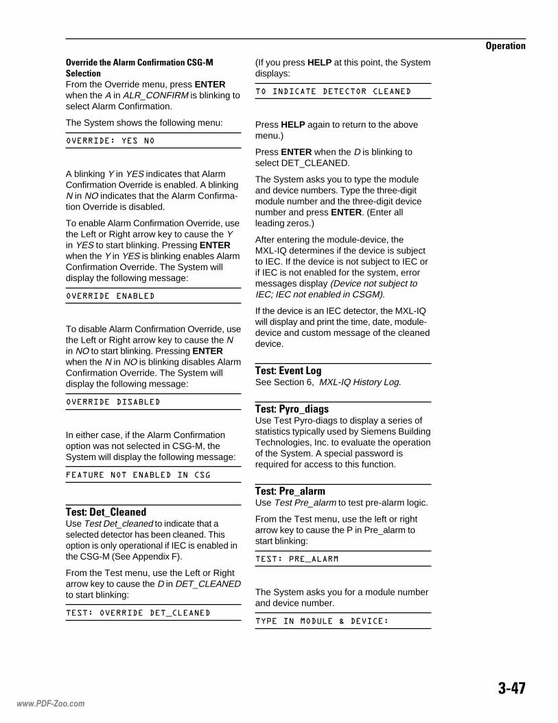
��#+
���������
�%�������0�� ������3����������5���� �*����From the Override menu, press ENTERwhen the A in ALR_CONFIRM is blinking toselect Alarm Confirmation.
The System shows the following menu:
�)����.�+�������
A blinking Y in YES indicates that AlarmConfirmation Override is enabled. A blinkingN in NO indicates that the Alarm Confirma-tion Override is disabled.
To enable Alarm Confirmation Override, usethe Left or Right arrow key to cause the Yin YES to start blinking. Pressing ENTERwhen the Y in YES is blinking enables AlarmConfirmation Override. The System willdisplay the following message:
�)����.������.
To disable Alarm Confirmation Override, usethe Left or Right arrow key to cause the Nin NO to start blinking. Pressing ENTERwhen the N in NO is blinking disables AlarmConfirmation Override. The System willdisplay the following message:
�)����.��.����.
In either case, if the Alarm Confirmationoption was not selected in CSG-M, theSystem will display the following message:
:��������������.���� �6
����>���D� �����Use Test Det_cleaned to indicate that aselected detector has been cleaned. Thisoption is only operational if IEC is enabled inthe CSG-M (See Appendix F).
From the Test menu, use the Left or Rightarrow key to cause the D in DET_CLEANEDto start blinking:
����+��)����.��.��� ���.
(If you press HELP at this point, the Systemdisplays:
�����.� ���.��� ���� ���.
Press HELP again to return to the abovemenu.)
Press ENTER when the D is blinking toselect DET_CLEANED.
The System asks you to type the moduleand device numbers. Type the three-digitmodule number and the three-digit devicenumber and press ENTER. (Enter allleading zeros.)
After entering the module-device, theMXL-IQ determines if the device is subjectto IEC. If the device is not subject to IEC orif IEC is not enabled for the system, errormessages display (Device not subject toIEC; IEC not enabled in CSGM).
If the device is an IEC detector, the MXL-IQwill display and print the time, date, module-device and custom message of the cleaneddevice.
����>4%���!�"See Section 6, MXL-IQ History Log.
����>1���D���"�Use Test Pyro-diags to display a series ofstatistics typically used by Siemens BuildingTechnologies, Inc. to evaluate the operationof the System. A special password isrequired for access to this function.
����>1��D� ���Use Test Pre_alarm to test pre-alarm logic.
From the Test menu, use the left or rightarrow key to cause the P in Pre_alarm tostart blinking:
����+�(�����
The System asks you for a module numberand device number.
��(�������.���;�.�)� �+
www.PDF-Zoo.com

��#;
���������
Type the three-digit module number andthe three-digit device number using thenumeric keypad and press ENTER.
The System then sends information to forcethis detector into pre-alarm. Once it pre-alarms, or after a delay, the MXL-IQ thenrestores the detector to its proper pre-alarmsetting.
����>���D��%�*��Use Test ASD_Devices to disable ASDparameters and allow timely response totest gas.
From the Test menu, use the Left or Rightarrow key to cause the A in ASD_Devicesto start blinking.
(If you press HELP at this point, the systemdisplays:
����+��.�.��� ����
Press HELP again to return to the Testmenu.)
Press ENTER to test the ASD devicespresent in the system. The System dis-plays:
������6��:��.�.�)� ������.
Press the ENTER key again and theSystem displays:
������6��:��.�.�)� ��.����.
Press the ENTER key to toggle betweenTesting Enabled (Trouble In) and TestingDisabled (Trouble Out). When togglingbetween Testing Enabled and TestingDisabled, there is a three minute timeperiod that separates the two states.
Activating the ASD_Devices command willpost a Trouble into the system which will beprinted out as:
��$ %�"�&4��*-���9��7�*-�� 6��9������
.9�N��"�%"� ��!'�$��$4&���N�
��,��"��&46�"4�%�",������!�4"�
Pressing ENTER a second time will causethe following message to be printed out:
��$ %�"�$ ���*-���9��*�*��� 6��9������
.+�N��"�%"� ��!'�$��$4&���N�
��,��"��&46�,&��%�",������!�4"�
If Test ASD_Devices is activated and leftalone, the system will automatically disablethe test (time out) after four hours.
Test ASD_Devices is inhibited while thesystem is initializing or resetting.
����>�������F�Use Test Summarize to ignore knowntroubles, and instead view one summarizedtrouble for an entire module. This is typicallyused during installation and commissioning.
Select Summarize and press ENTER. TheSystem displays the following menu:
��$� �������������::
����>�������F���� �*�D����Use Test Summarize Select_Mods to scrollthrough all installed (CSG-M) moduleaddresses and enable/disable the summa-rize feature for each module address.Choose Select_Mods and press ENTER.The System displays the following:
��*���������
Press NEXT and the System displays:
��1���������
The System flashes the currently activesummarize selection for the moduleaddress. The operator may then press theright or left arrow keys to highlight eitherYES or NO and then press the ENTER keyto accept and program the selection. WhenENTER is pressed, the System scrolls tothe next installed module address. The Uparrow key terminates the Select_Modsmode.
All Select_Mods selections remain intactuntil the System is turned off, even ifsummarize mode is toggled.
www.PDF-Zoo.com

��#<
���������
• One trouble is posted per moduleaddress, regardless of how manytroubles are detected at that moduleaddress.
• A trouble is not posted unless at leastone trouble is detected at that moduleaddress.
• The trouble report is consistent withexisting MXL-IQ trouble messages andthe text reads Troubles summarized.
• The MXL-IQ only reports TRBL-INswhen summary mode is enabled at anaddress.
• Alarm, supervisory, security, and statusevent reporting are not effected.
Modules which are NOT selected forsummary report their troubles as usual,even if summary mode is turned on forother module addresses.
When a module address is summarized,individually occurring troubles are notbroadcast to XNET; the single Troublessummarized trouble is broadcast to XNET.The Troubles summarized trouble isimplemented as any other system trouble,being logged to history, taking up one of the300 trouble slots, and appearing in ListTroubles requests. All summarize selec-tions are unaffected through RESET anddefault to CSG-M setting at power up.
����>�������F�����When Summarize OFF is selected, theSystem annunciates the following trouble:
�����%� �%%�����!�!3�������������
and turns off the Partial System DisableLED. Preexisting Troubles summarizedevents remain and the System reverts tonormal trouble reporting and processing forall new troubles.
����>�������F����When Summarize ON is selected, theSystem annunciates the following trouble:
�����%� �%%�����!�!3������������
and turns on the Partial System DisableLED. The System displays one summarizedtrouble for the total system.
����>����� D�*��%���Use Test Manual_Activate to:
• Perform testing on input points and theassociated output logic expected whenthe point is activated.
• Generate alarms and associated outputactivations.
Select Manual_Activate and press ENTER.The System asks you for a module numberand device number.
������!����"$��;�.��� �+��4
Type the three-digit module number andthree-digit device number using the nu-meric keypad and press ENTER. Uponentering the device address, the Systemperforms as follows based on the pointtype:
������� ����������������
� � ������� ��� ������ ������
���� �� �� ��
������ ��
��� ��� ��������������� �������
������� �� �� ���������� � �����
����� ��� ������� ��� �������� ���
����� ����������� ��� ����� ���������
���������������� ����� �� �� ������
���� ����
������
��� ��� ����� �� � ������ ���� �������
�� �������� �� � ����� ��� ������� ��
����� ��� ��� ������ ��� ��� ��� ������
������� ��� �� �� �� ������
����>����� D�*��%��������This provides a remote switch that uponactivation/deactivation of the TRI, theMXL-IQ reads the module-device addressprovided and performs the operationsoutlined above. This use is primarily for, butnot limited to, testing intelligent ductdetectors.
www.PDF-Zoo.com

��2:
���������
www.PDF-Zoo.com

�����������
���� ���If the System is connected to the FireDepartment, or activates an externalSystem (for example, a leased lineconnection), disarm the relatedoutputs before servicing to preventactivation. Notify persons in thefacility that you are conducting aSystem test so that they can ignoreany alarms that sound during testing.Be sure to reset the System at theend of the inspection.
To ensure maximum safety, follow theprocedure described below. To ensureproper and reliable operation, we recom-mend the following inspection and testingschedule:
���������������1. Check the sensitivity of each detector,
using the List Sensitivity menu (Seepage 3-26). Refer to Appendix B for alist of acceptable detector sensitivityranges.
2. If the PARTIAL SYSTEM DISABLELED is lit, check that all appropriatedetectors are armed, using the ControlArm/dis menu (See page 3-38).
3. Activate a detector or alarm-initiatingdevice. To test for GoNo Go operation,
use �������������� ����
Test Gas P/N 315-282747, following theinstructions on the label. Check that thedetector LED lights and that the properindication is given at the Control Panel.
4. Verify that an alarm can be acknowledgedand that the System can be silenced andreset (See Acknowledge Alarms onpage 3-18).
5. Verify the time and date setting of theSystem clock (See Test Set_Time onpage 3-43).
�������� �1. Check that the System operates as
programmed by CSG-M and inaccordance with specifications.
2. Perform any other applicable testsrequired by national or local fire codes.
�������� ������Fuse ratings are as follows:
���� ��� ����
��������
����� ������ �
�������������������
���� ��������� ���� ���������!����� �������������� ���������!�
The fuses are located on the upper portionof the SMB-2 (See Figure 2, page 1-4).
���������
����������� ������ ����
���www.PDF-Zoo.com

���
������ � �!����"�������
��#$%&��'##��()Troubleshooting both the external wiring andthe MXL-IQ System wiring follows the stepsin System Function Checkout on page2-16. If a fault occurs, refer to the Trouble-shooting Guide. Locate the type of fault orany trouble message displayed and followthe directions in the Corrective Actioncolumn.
Sometimes you can locate a fault quicklyusing the Troubleshooting Guide. Whenthis is not possible, continue with thecheckout procedure on page 2-16 and thenthe Troubleshooting Guide until all faultsand troubles are corrected. Then repeat thecheckout procedure to ensure that noadditional problems were introduced andthat the original problem was corrected.
�*%&���+��#$%&��'##��()�)$�,�
This guide assumes that all modules, devices, and wiring are installed.
Note: Do NOT change modules or wiring unless power is OFF. If available, use your printer duringtroubleshooting operations.
MOTPMYS ESUACELBABORP NOITCAEVITCERROC
.1 ;tiltonsiDELREWOPsi4-BKMnoyalpsid
.knalb
yrettaBCAoN rekaerbtiucricehtdna2-BMSehtno2Fdna1FsesufkcehC.yrettabdnaCAkcehC.gniriwyrettabdnaCAkcehC.6-SPMehtno
rof4-BKMdna2-BMSehtneewtebelbacehtkcehc,KOerasnoitcennocrewopfI.noitallatsnireporp
.2 ,nosiDELREWOP.knalbsiyalpsid4-BKM
.4-BKMehtnomelborP kcehcdna4-BKMehtevomeR.draob1-NNAehtno41RlortnoctsartnoctsujdA.tiecalper,evitcefedsi4-BKMfI.yalpsidehtot1-NNAmorfelbac
.3 swohsyalpsid4-BKMtluafedgniwollofeht
:egassemSUREBREC
LXMSCINORTORYP
4-BKMnosserddareporpmI
neewtebnoitacinummocoN.4-BKMdna2-BMS
.4-BKMevitcefeD
evitcefed,dellatsni4/2-MOMfI.)s(seludomkrowten
2-BMSevitcefeD
rofsnoitcurtsninoitallatsniehteeS.1Sgnisu4-BKMehtnognittessserddatcerroC.4-2egap,4-BKMeht
.evitcefedfielbacehtecalpeR.4-BKMehtdna2-BMSehtneewtebelbacehtkcehC
.4-BKMehtecalpeR
tcennocer,devlosermleborpfI.2-BMSehtmorf4/2-MOMehttcennocsiDenoseludomllallatsnieR.4/2-MOMmorfseludomllaevomerdna4/2-MOM
.ruccoerotsmelborpehtesuactahtynaecalpeR.emitata
2-BMSecalpeR
.4 noselbuorteciveD.spoolgolana
dnagniriwpoolnisrorrE.secivedfonoitallatsni
ediuGtuokcehCgniriWdleiFehtgnisu.cte,snepo,strohsrofgniriwpoolkcehC.)11-2egap(
ehteeS.s6B1-MZCeraro,secivedseireSLIroIerasecivedgolanallatahtkcehC.sexidneppaehtnisecivedelbitapmocfotsil
.dellatsnierasecivedllatahtkcehC
.M-GSCmorftuotnirpnoitarugifnocehthtiwylpmocdellatsnisecivedllatahtkcehC
kcehC.deriuqersasDIecivedtcerrocdnaselbuortDIroftsilelbuortdetnirpkcehC.dnopserotliaftahtsecivedecalpeR.retseTremmargorP23-IPFehtgnisusecived
www.PDF-Zoo.com

��-
������ � �!����"�������
�*%&���+��#$%&��'##��()�)$�,��./������!0
MOTPMYS ESUACELBABORP NOITCAEVITCERROC
.5 noitacifitonhtiwelbuorTstiucricecnailppa
.)sCAN(
ylreporpmirotsiserenil-fo-dnE.dellatsnitonro
secnailppanoitacifitoN.dellatsniylreporpmi
noitacifitonelbitapmocnI.detcennocecnailppa
.snoitcnufcigollortnocnirorrE
ehtotgnidroccadellatsnisidnaW½,K2.2sirotsiserenil-fo-dneehttahtkcehC.snoitcurtsni
ecivedtcerrocdnasedoidgniziralopfoecneserprofsecnailppanoitacifitonkcehC.gniriw
tuokcehCgniriWdleiFehtesU.).cte,snepo,strohs(gniriwreporprofsCANkcehC.11-2egap,ediuG
ecalpeR.secnailppanoitacifitonelbitapmocfotsilarof363690-513N/PkcehC.secivedelbitapmocni
daolerdnatcerroc;M-GSCmorftuotnirpehtgnisusnoitcnufcigolehtkcehC.2-BMSehtotniM-GSCmorfmetsySeht
.6 secivedtuptuOmetsySotdetcennoc.krowtonodsyaler
tupuorofecruosrewoPtonrognissimsecived
.detcennoc
detcennocfogniriwreporpmI.secived
toneraseciveddetcennoC.ecruosrewophtiwelbitapmoc
.elbaliavasirewoptahtdnadetcennocsiecruosrewopehttahtkcehC
.deriwylreporperasecivedtuptuotahtkcehC
.elbitapmocerasecivedtupuodnaecruosrewoptahtkcehC
.7 astroper6B1-MZC.elbuort
.6B1-MZCotrewopoN
gnitaitininororregniriW.tiucricecived
tsumrewopCD;tupnirewopkcehc6B1-MZCehttA.3Fesufkcehc,2-BMSehtnO.ytiralopkcehC.CDV13-61eb
.)W¼,K7.4(rotsiserenil-fo-dnegnissimrotcerrocnirosneporofkcehC
.8 od4/2-MOMniseludoM.krowton
.4/2-MOMotrewopoN
neewtebsnoitacinummocoN.4/2-MOMdna2-BMS
ylreporptoneraseludoM.srotcennocegdenidetaes
ylreporptoneraseludoM.desserdda
.)5P(4/2-MOMehtdna)3P(2-BMSehtneewtebsrotcennocelbacrewopkcehC.evitcefedfi,elbacrewopehtecalpeR
ehtdna)6P(2-BMSehtneewtebsnoitcennocelbacsnoitacinummockcehC.evitcefedfi,elbacsnoitacinummocehtecalpeR.)7P(4/2-MOM
.seludomllataeserdnaevomeR
eeS(M-GSCmorfnoitarugifnocdetnirpehtgnisuyltcerrocseludomehtsserddA.)183090-513N/P,launaMgnimmargorPM-GSC
.9 dnopsertonseod4-MSCcigoltuptuoot
.sdnammoc
.nwolberasesuF
ylreporpmisi4-MSC.derugifnoc
noitacifitonelbitapmocnI.detcennocerasecnailppa
.snoitcnufcigollortnocnirorrE
.4-MSCevitcefeD
ecalpeR.)11-2egap(ediuGtuokcehCgniriWdleiFehtgnisustrohsrofgniriwkcehC.sesuf
4-MSCehtrofsnoitcurtsninoitallatsniehtgnisunoitarugifnocehttcerrocdnakcehCM-GSCeeS(M-GSCmorfnoitarugifnocdetnirpehtdna)458090-513N/P(
.)183090-513N/P,launaMgnimmargorP
ecalpeR.secnacilppanoitacifitonelbitapmocfotsilarof363690-513N/PkcehC.secivedelbitapmocni
daolerdnatcerroc;M-GSCmorftuotnirpehtgnisusnoitcnufcigolehtkcehC,launaMgnimmargorPM-GSCeeS(2-BMSehtotniM-GSCmorfmetsySeht
.)183090-513N/P
.4-MSCecalpeR
www.PDF-Zoo.com
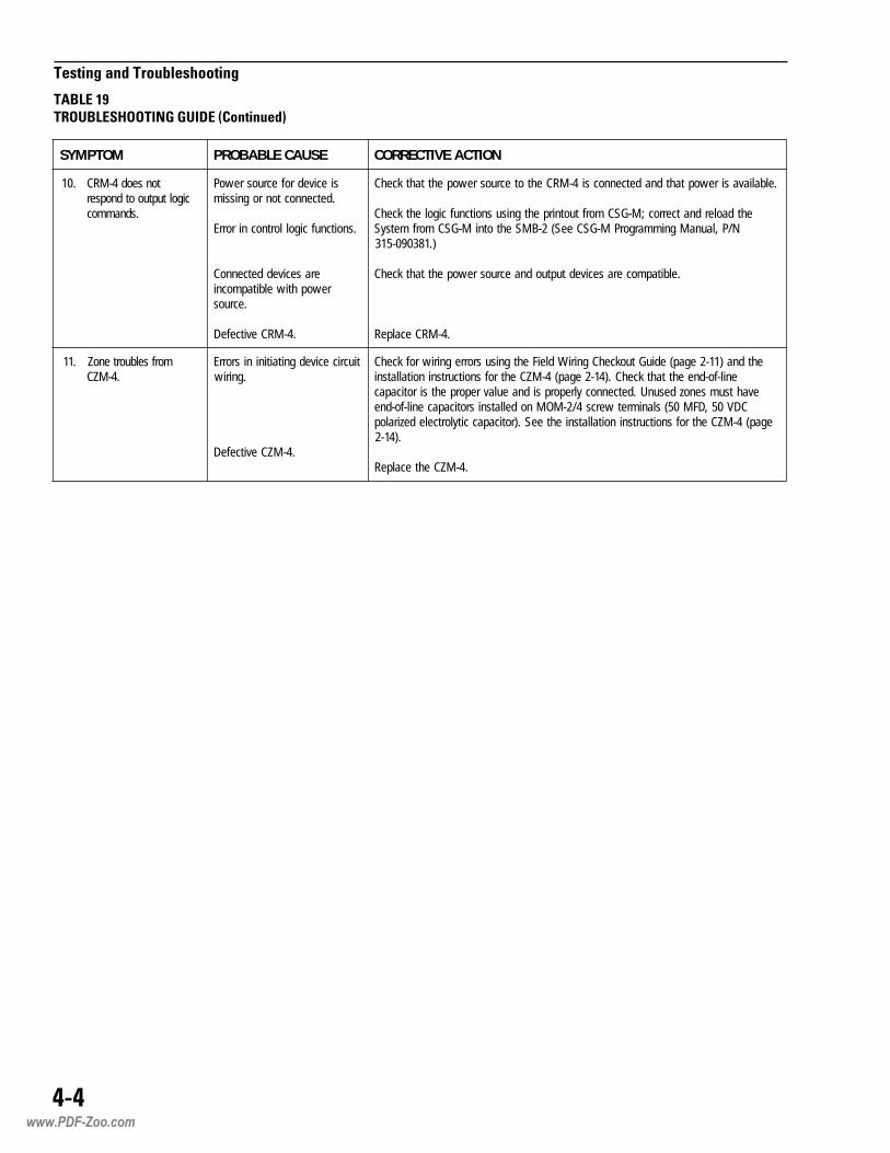
���
������ � �!����"�������
�*%&���+��#$%&��'##��()�)$�,��./������!0
MOTPMYS ESUACELBABORP NOITCAEVITCERROC
.01 tonseod4-MRCcigoltuptuootdnopser
.sdnammoc
siecivedrofecruosrewoP.detcennoctonrognissim
.snoitcnufcigollortnocnirorrE
eraseciveddetcennoCrewophtiwelbitapmocni
.ecruos
.4-MRCevitcefeD
.elbaliavasirewoptahtdnadetcennocsi4-MRCehtotecruosrewopehttahtkcehC
ehtdaolerdnatcerroc;M-GSCmorftuotnirpehtgnisusnoitcnufcigolehtkcehCN/P,launaMgnimmargorPM-GSCeeS(2-BMSehtotniM-GSCmorfmetsyS
).183090-513
.elbitapmocerasecivedtuptuodnaecruosrewopehttahtkcehC
.4-MRCecalpeR
.11 morfselbuortenoZ.4-MZC
tiucricecivedgnitaitininisrorrE.gniriw
.4-MZCevitcefeD
ehtdna)11-2egap(ediuGtuokcehCgniriWdleiFehtgnisusrorregniriwrofkcehCenil-fo-dneehttahtkcehC.)41-2egap(4-MZCehtrofsnoitcurtsninoitallatsni
evahtsumsenozdesunU.detcennocylreporpsidnaeulavreporpehtsiroticapacCDV05,DFM05(slanimretwercs4/2-MOMnodellatsnisroticapacenil-fo-dne
egap(4-MZCehtrofsnoitcurtsninoitallatsniehteeS.)roticapaccitylortceledeziralop.)41-2
.4-MZCehtecalpeR
www.PDF-Zoo.com

A Walktest of the MXL-IQ System enablesa qualified technician to test the operationof input points on the MXL-IQ with orwithout disabling the entire fire alarmsystem. Testing can be either silent or withaudible feedback in the following ways:
1. Entire system
2. ALD loop (60 subaddresses)
3. CZM-4 module (4 zones)
4. Conventional zone (individualCZM-1B6 or CZM-4 zone)
5. MOI-7 (MID-16) inputs (128subaddresses)
If a printer is installed, a printed record ofthe test is made.
The Walktest is available with MXL-IQOperating Software. You must enter your1-5 digit password before you can use theWalktest functions. Enter the Walktestthrough the MXL-IQ Main Menu (SeeChapter 3, Operating Instructions).
The MXL-IQ Main Menu structure withWalktest included is:
�������������
ACKNOWLEDGE
LIST
CONTROL
TEST
WALKTEST
The table below shows the selections in the Walktest Menu andtheir related help messages.
��������
�������������������������
������������
02ELBATuneMtsetklaW
TSETKLAW EGASSEMPLEH
DUAwmetsyS sDUAhtiwmetsySlluFtseT
DUAwpooL sDUAweludoM4-MZC/)puorg61-DIM(7-IOM/pooLDLAtseT
DUAwenoZ sDUAhtiwenoZ6B1-MZC/4-MZCtseT
LISmetyS metsySlluFtseTtneliS
LISpooL sDUAweludoM4-MZC/)puorg61-DIM(7-IOM/pooLDLAtseTtneliS
LISenoZ enoZ6B1-MZC/4-MZCtseTtneliS
lecnaC ssergorpnitsetklaWlecnaC
dnetxE tfelsruoh4otremittsetteseR
�www.PDF-Zoo.com
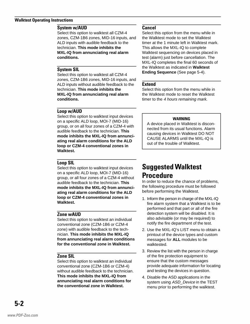
�
������������������������������
������� !"��Select this option to walktest all CZM-4zones, CZM-1B6 zones, MID-16 inputs, andALD inputs with audible feedback to thetechnician. This mode inhibits theMXL-IQ from annunciating real alarmconditions.
���������#Select this option to walktest all CZM-4zones, CZM-1B6 zones, MID-16 inputs, andALD inputs without audible feedback to thetechnician. This mode inhibits theMXL-IQ from annunciating real alarmconditions.
#���� !"��Select this option to walktest input deviceson a specific ALD loop, MOI-7 (MID-16)group, or on all four zones of a CZM-4 withaudible feedback to the technician. Thismode inhibits the MXL-IQ from annunci-ating real alarm conditions for the ALDloop or CZM-4 conventional zones inWalktest.
#������#Select this option to walktest input deviceson a specific ALD loop, MOI-7 (MID-16)group, or all four zones of a CZM-4 withoutaudible feedback to the technician. Thismode inhibits the MXL-IQ from annunci-ating real alarm conditions for the ALDloop or CZM-4 conventional zones inWalktest.
$���� "��Select this option to walktest an individualconventional zone (CZM-1B6 or CZM-4zone) with audible feedback to the tech-nician. This mode inhibits the MXL-IQfrom annunciating real alarm conditionsfor the conventional zone in Walktest.
$������#Select this option to walktest an individualconventional zone (CZM-1B6 or CZM-4)without audible feedback to the technician.This mode inhibits the MXL-IQ fromannunciating real alarm conditions forthe conventional zone in Walktest.
������Select this option from the menu while inthe Walktest mode to set the Walktesttimer at the 1 minute left in Walktest mark.This allows the MXL-IQ to completeWalktest sequencing on devices placed intest (alarm) just before cancellation. TheMXL-IQ completes the final 60 seconds ofthe Walktest as indicated in WalktestEnding Sequence (See page 5-4).
%&���'Select this option from the menu while inthe Walktest mode to reset the Walktesttimer to the 4 hours remaining mark.
"����(A device placed in Walktest is discon-nected from its usual functions. Alarmcausing devices in Walktest DO NOTCAUSE ALARMS until the MXL-IQ isout of the trouble of Walktest.
��������'� �������)����'���In order to reduce the chance of problems,the following procedure must be followedbefore performing the Walktest.
1. Inform the person in charge of the MXL-IQfire alarm system that a Walktest is to beperformed and that part or all of the firedetection system will be disabled. It isalso advisable (or may be required) tonotify the fire department of the test.
2. Use the MXL-IQ’s LIST menu to obtain aprintout of the device types and custommessages for ALL modules to bewalktested.
3. Review the list with the person in chargeof the fire protection equipment toensure that the custom messagesprovide adequate information for locatingand testing the devices in question.
4. Disable the ASD applications in thesystem using ASD_Device in the TESTmenu prior to performing the walktest.
www.PDF-Zoo.com

*
������������������������������
Once the test ASD device option has beenenabled using the test menu, the testershould wait 3 minutes before attemptingto test the ASD devices. This will ensurethat the ASD R-Algorithm has beendisabled for the test. When the test iscomplete, press ASD_Device again tore-enable ASD R-Algorithm, or it willautomatically re-enable after 4 hours.The System will not reset if the ASDdevices are still in the disabled state.
5. Initiate Walktest. Test devices in apredetermined, orderly sequence.
6. When the Walktest is complete (timedout/canceled), acknowledge the OUTOF TROUBLE condition and reset theMXL-IQ. When the system indicatesSYSTEM NORMAL, the test is complete.
WARNING: A device placed in Walktest isdisconnected from its usual functions.Alarm causing devices in Walktest do NOTcause alarms until the MXL-IQ is out of thetrouble of Walktest.
In both the silent (SIL) and audible (wAUD)Walktest modes, information is displayed onthe Control Panel LCD and printed on theprinter (if a printer is installed). The audible(wAUD) mode also provides audible feed-back to the technician with the testing of eachinput device. Audible feedback is NOTincluded on circuits with zone coded audibles.A system with only zone coded audiblesALWAYS results in a silent Walktest.
NOTE: The Walktest Ending Sequence(See page 5-4) occurs with audible warn-ings in the audible Walktest modes.
NOTE: The MXL-IQ will not allow awalktest to be initiated if there are Alarmsor Supervisory events in the event queues.
���������+��������To place all CZM-4 zones, MID-16 inputs,and ALD input devices in Walktest, followthe procedure below:
• Move the cursor to the S in SystemwAUD for a Walktest with audiblefeedback or to the S in System SIL fora silent Walktest.
• Press ENTER.
• The following events take place:
- the PARTIAL SYSTEM DISABLELED lights
- the TROUBLE LED flashes
- the internal audible sounds
- the Walktest activated trouble for theMXL-IQ records on the trouble list
- if a printer is installed, the trouble isalso printed
• The LCD display on the MKB-4 reads:
������������ ����� ����� ���������������� �� ������
• Press ENTER or wait 60 seconds andthe display reads:
�������������������������������������� �� ������
• Press ENTER, or wait 60 seconds andthe MXL-IQ returns to the Walktestmenu. (The MXL-IQ is in systemWalktest.) The LCD indicates the timeremaining in Walktest in the last fivepositions on the display. The time isindicated in HH:MM (hours:minutes) untilless than one hour remains, then it isindicated in MM:SS (minutes:seconds).
• Locate the device to be tested and placethat device in alarm (or trouble). Whenthe event is reported to the MXL-IQ, thefollowing sequence occurs:
1. When the System is in the audibleWalktest mode, all silenceable and non-silenceable audibles that are not alreadyactive or disarmed sound the code,depending on how the device is used inthe CSG-M. The codes are:
����� ����
����� ��������� ������
����������� �������������� ����������
������� ��������� �����
�����!�� �������������� ���������
��"��#������ ��������� �����$
www.PDF-Zoo.com
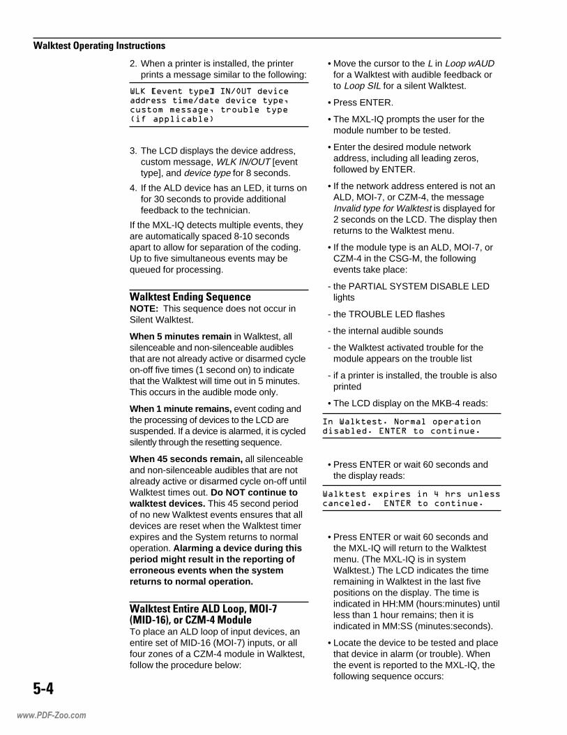
,
������������������������������
2. When a printer is installed, the printerprints a message similar to the following:
�������������� �������������������������������������������������������������� �!�����������"
3. The LCD displays the device address,custom message, WLK IN/OUT [eventtype], and device type for 8 seconds.
4. If the ALD device has an LED, it turns onfor 30 seconds to provide additionalfeedback to the technician.
If the MXL-IQ detects multiple events, theyare automatically spaced 8-10 secondsapart to allow for separation of the coding.Up to five simultaneous events may bequeued for processing.
��������%�'������-�����NOTE: This sequence does not occur inSilent Walktest.
When 5 minutes remain in Walktest, allsilenceable and non-silenceable audiblesthat are not already active or disarmed cycleon-off five times (1 second on) to indicatethat the Walktest will time out in 5 minutes.This occurs in the audible mode only.
When 1 minute remains, event coding andthe processing of devices to the LCD aresuspended. If a device is alarmed, it is cycledsilently through the resetting sequence.
When 45 seconds remain, all silenceableand non-silenceable audibles that are notalready active or disarmed cycle on-off untilWalktest times out. Do NOT continue towalktest devices. This 45 second periodof no new Walktest events ensures that alldevices are reset when the Walktest timerexpires and the System returns to normaloperation. Alarming a device during thisperiod might result in the reporting oferroneous events when the systemreturns to normal operation.
��������%������"#��#���.�/��01/���23.�����$/,�/�'���To place an ALD loop of input devices, anentire set of MID-16 (MOI-7) inputs, or allfour zones of a CZM-4 module in Walktest,follow the procedure below:
• Move the cursor to the L in Loop wAUDfor a Walktest with audible feedback orto Loop SIL for a silent Walktest.
• Press ENTER.
• The MXL-IQ prompts the user for themodule number to be tested.
• Enter the desired module networkaddress, including all leading zeros,followed by ENTER.
• If the network address entered is not anALD, MOI-7, or CZM-4, the messageInvalid type for Walktest is displayed for2 seconds on the LCD. The display thenreturns to the Walktest menu.
• If the module type is an ALD, MOI-7, orCZM-4 in the CSG-M, the followingevents take place:
- the PARTIAL SYSTEM DISABLE LEDlights
- the TROUBLE LED flashes
- the internal audible sounds
- the Walktest activated trouble for themodule appears on the trouble list
- if a printer is installed, the trouble is alsoprinted
• The LCD display on the MKB-4 reads:
�����#��$������������������������$�%��%&����������$
• Press ENTER or wait 60 seconds andthe display reads:
���#����'���������(�)�����������������$��%��%&����������$
• Press ENTER or wait 60 seconds andthe MXL-IQ will return to the Walktestmenu. (The MXL-IQ is in systemWalktest.) The LCD indicates the timeremaining in Walktest in the last fivepositions on the display. The time isindicated in HH:MM (hours:minutes) untilless than 1 hour remains; then it isindicated in MM:SS (minutes:seconds).
• Locate the device to be tested and placethat device in alarm (or trouble). Whenthe event is reported to the MXL-IQ, thefollowing sequence occurs:
www.PDF-Zoo.com

������������������������������
1. When the System is in the audibleWalktest mode, all silenceable and non-silenceable audibles that are not alreadyactive or disarmed sound the code,depending on how the device is used inthe CSG-M. The codes are as follows:
����� ����
����� ��������� ������
����������� �������������� ����������
������� ��������� �����
�����!�� �������������� ���������
��"��#������ ��������� �����$
2. When a printer is installed, the printerprints a message similar to the following:
�������������� ��������������������������������������������������������������� �!�����������"
3. The LCD displays the device address,custom message, WLK IN/OUT [eventtype], and device type for 8 seconds.
4. If the ALD device has an LED, it turns onfor 30 seconds to provide additionalfeedback to the technician.
If the MXL-IQ detects multiple events, theyare automatically spaced 8-10 secondsapart to allow for separation of the coding.Up to five simultaneous events may bequeued for processing.
��������%�'������-�����NOTE: This sequence does not occur inSilent Walktest.
When 5 minutes remain in Walktest, allsilenceable and non-silenceable audiblesthat are not already active or disarmed cycleon-off five times (1 second on) to indicatethat the Walktest will time out in 5 minutes.This occurs in the audible mode only.
When 1 minute remains, event coding andthe processing of devices to the LCD aresuspended. If a device is alarmed, it is cycledsilently through the resetting sequence.
When 45 seconds remain, all silenceableand non-silenceable audibles that are notalready active or disarmed cycle on-off untilWalktest times out. Do NOT continue towalktest devices. This 45 second periodof no new Walktest events ensures that alldevices are reset when the Walktest timerexpires and the System returns to normaloperation. Alarming a device during thisperiod might result in the reporting oferroneous events when the systemreturns to normal operation.
NOTE: If an alarm or supervisory isreported from a device that is NOT inWalktest, the Walktest is suspendedimmediately. No further Walktest eventsare annunciated or coded. The Walktestremains running in the background of theMXL-IQ until it times out or is canceled.
"����(4When performing a partial systemWalktest, DO NOT TEST any devicesthat are not in the Walktest as this willcause an alarm in the system.
����������'�5�'�����$/�62�����$/,$���To place an individual CZM-1B6 or CZM-4zone in Walktest, follow the procedurebelow:
• Move the cursor to the Z in Zone wAUDfor a Walktest with audible feedback orZ SIL for a silent Walktest.
• Press ENTER.
• The MXL-IQ prompts the user for themodule and device number to be tested.
• Enter the desired network address,including all leading zeros, followed byENTER.
• If the network address entered is not aCZM-4 or CZM-1B6 zone, the messageInvalid type for Walktest is displayed for2 seconds on the LCD. The display thenreturns to the Walktest menu.
• If the module type is a CZM-1B6 orCZM-4 zone in the CSG-M, the followingevents take place:
www.PDF-Zoo.com

2
������������������������������
- the PARTIAL SYSTEM DISABLE LEDlights
- the TROUBLE LED flashes
- the internal audible sounds
- the Walktest activated trouble for thezone records on the trouble list
- if a printer is installed, the trouble is alsoprinted
• The LCD display on the MKB-4 reads:
�����#��������������������������$�%��%&����������$
• Press ENTER or wait 60 seconds andthe display reads:
���#����'���������(�)�����������������$�%��%&����������$
• Press ENTER or wait 60 seconds andthe MXL-IQ returns to the Walktestmenu. (The MXL-IQ is in systemWalktest.) The LCD indicates the timeremaining in Walktest in the last fivepositions on the display. The time isindicated in HH:MM (hours:minutes) untilless than 1 hour remains, then it isindicated in MM:SS (minutes:seconds).
• Locate the device to be tested andplace that device in alarm (or trouble).When the event is reported to theMXL-IQ, the following sequence occurs:
1. When the System is in the audibleWalktest mode, all silenceable and non-silenceable audibles that are not alreadyactive or disarmed sound the code,depending on the device usage in theCSG-M. The codes are as follows:
����� ����
����� ��������� ������
����������� �������������� ����������
������� ��������� �����
�����!�� �������������� ���������
��"��#������ ��������� �����$
2. When a printer is installed, the printerprints a message similar to the following:
�������������� �������������������������������������������������������������� �!�����������"
3. The LCD displays the device address,custom message, WLK IN/OUT [eventtype], and device type for 8 seconds.
4. If the ALD device has an LED, it turns onfor 30 seconds to provide additionalfeedback to the technician.
If the MXL-IQ detects multiple events, theyare automatically spaced 8-10 secondsapart to allow for separation of the coding.Up to five simultaneous events may bequeued for processing.
When 5 minutes remain, the system begins theWalktest Ending Sequence (See page 5-5).
NOTE: If an alarm or supervisory isreported from a device that is NOT inWalktest, the Walktest is suspendedimmediately. No further Walktest eventsare annunciated or coded. The Walktestremains running in the background of theMXL-IQ until it times out or is canceled.
"����(4When performing a partial systemWalktest, DO NOT TEST any devicesthat are not in the Walktest as this willcause an alarm in the system.
www.PDF-Zoo.com

The MXL-IQ history system has five majorparts. They are:
1. CSG-M options that control the type andnumber of events the MXL-IQ records.
2. Logging lists that record MXL-IQhardware events.
3. Event viewing and listing in the MXL-IQthrough the MKB-4 and attached printer.
4. History removal and collation outside theMXL-IQ.
5. Report generation and analysis on anexternal PC.
���������� ������The CSG-M gives the designer a set ofoptions to use for operating the historysystem. The designer must first decidewhether or not to use the history option. Ifhe chooses to use it, he must select themode of logging and which event types toinclude in the log. The History RecordingOptions are selected from the Options,System Message, Authorizations menu.(See Screen 1.)
To access the history option, move thecursor to highlight History RecordingOptions and press ENTER. The historyrecording option selection screen is thendisplayed as shown in Screen 2, page 6-2.
Screen 1Options, System Message, Authorizations
Fire Protection Company Name
CSG-M Memory=2900 used, 316848 free CONFIG => TEST1 Options, System Message, Authorizations
Options, System Message, Authorizations Other System Flags History Recording Options System Holidays
Press First Letter or Move Cursor to Highlight Selection, then ENTER
���
���������
���������
������������
www.PDF-Zoo.com

���
���� ����
Screen 2 shows the default conditions forthe history option when it is selected for thefirst time.
Keep in mind that the external data basemay not contain all events that were everdetected. The completeness of the database depends on whether the systemoperator extracts all event log informationbefore it is lost.
�������������The MXL-IQ has two mutually exclusiveways to log events:
1. Small list
2. Circular list
Screen 2History Recording Options
�� !!�����������In the small list logging mode, the MXL-IQstores up to 818 events (See Screen 3) innon-volatile memory. Non-volatile memoryis memory that is not lost when the power isremoved.
When the event storage area becomes80% full, a system trouble begins.
• the trouble audible sounds
• the trouble indicator lights
• the message Event Log 80% full showson the LCD display
• this trouble operates like any othertrouble in the system
When the event storage area becomes90% full, a new system trouble begins.
Fire Protection Company Name
CSG-M Memory=2900 used, 316852 free CONFIG => TEST1 History Recording Options
History mode -------------------> Small Log alarms ---------------------> YES Log troubles -------------------> YES Log supervisories --------------> YES Log securities -----------------> YES Log status ---------------------> NO Log verification ---------------> NO Log output ---------------------> NO Log resets ---------------------> YES Log block acks. ----------------> YES Log audible changes ------------> YES Log manual sens. changes -------> NO Log logic sens. changes --------> NO Log arm/disarm -----------------> YES Log energize/deenergize --------> YES Log time changes ---------------> YES Log passwords ------------------> YES Log overrides ------------------> NO Enable History Log Via MKB Menu > NO
Move Cursor to Select, ENTER to TOGGLE ESC = Prev. Menu
www.PDF-Zoo.com

��"
���� ����
• the trouble audible sounds
• the trouble indicator lights
• the message Event Log 90% full showson the LCD display
• this trouble operates like any othertrouble in the system
When the event log is full, an new troublecondition occurs which causes the troubleaudible to activate.
• the message Log FULL, Events will belost appears on the display panel
• upon reset this trouble reappears,replacing the 90% trouble message
• when the log is full, all new events arelost
This system encourages removing historyinformation into an external data basebefore the log overflows.
���#$! ���������In the circular logging mode, the MXL-IQguarantees that the most current 500
events are stored in non-volatile memory.Once all available storage is used, theoldest history entries are replaced by newerones. It is assumed that the end userselects this mode because he does notwish to maintain an external history database. Therefore, only two warning troublesare issued:
1. When the number of recorded eventsreaches 80% of the total.
2. When the number of recorded eventsreaches 90% of the total. Once thistrouble is acknowledged, it disappearsuntil 80% of events is reached in thenext cycle.
Using the circular logging mode does notprevent the storage of history informationinto an external data base. However, thereis a high probability of loosing old eventsbecause of the limited warnings given whenevents are about to be overwritten.
Beginning with MXL-IQ Rev. 6.0, the usercan suppress the Circular History Log FullTrouble. This option must be set in CSG-Mand is only available if the history is incircular mode.
Screen 3Display MXL-IQ Panel Info
Fire Protection Company Name
CSG-M Memory=2900 used, 316852 free CONFIG => TEST1 DISPLAY MXL-IQ Panel Info
MXL-IQ PANEL INFO:MXL-IQ ROM Version -------------------> Rev. 1.00MXL-IQ Main Board Version ------------> 2MXL-IQ Minimum Allowable Board Ver.---> Rev. 1.00RAM size -----------------------------> 163840 bytesEEROM size ---------------------------> 114688 bytesMXL-IQ Dictionary Version ------------> 0MXL-IQ Alt. Dictionary Version--------> 0History Memory Available -------------> 818 (11) elements (used)IEC Storage Memory Available ---------> 8189 bytes
PROGRAMMING INFO:Configuration Source Filename --------> TEST1Configuration Size -------------------> 2802 bytesLast Programming Date ----------------> Wed Mar 22 15:28:16 20XXConfiguration Revision Level ---------> 215Programming Info CHECKSUM ------------> 1085
ANY KEY TO CONTINUE
www.PDF-Zoo.com

��%
���� ����
��������������!�#���
The system designer can log one or manyevent types. The selection is determined bythe system requirements, the amount ofevent storage, and the external data basedesign. The following list summarizes eventtypes that can be selected.
* ALARMS
* TROUBLES
* SUPERVISORIES
* SECURITIES
STATUS CHANGES
DEVICE VERIFICATION
OUTPUT ACTIVATIONS
* RESET
* BLOCK ACKNOWLEDGE
* AUDIBLE CONTROL
SET SENSITIVITY
AUTO SET SENSITIVITY
* ARM/DISARM
* ENERGIZE/DE-ENERGIZE
* SET TIME
* PASSWORD
OVERRIDE
*The items marked with an asterisk are setas default when the logging option is firstselected. At least one event type must beselected.
�&'����$��������(� )!�*��� )!�� ���(� ����� Effective with MXL-IQ Revision 6.0, thisoption allows the user with the highest levelpassword to turn on, turn off, or erase theHistory, provided that this system optionhas been enabled in the CSG-M and theHistory mode is other than NONE (that is,either small or circular).
(� )!����������� ���������������From the Main Menu, select SystemConfiguration Edit, then select Options,
System Message Authorization, then selectHistory Recording Options. From HistoryRecording Options, move the cursor downto the line that reads Enable History Log ViaMKB Menu, and select YES to compile theCSG-M program and download it to theMXL-IQ. (Refer to Screen 2.)
+��������&'����$Go to the TEST menu, move the cursor tothe right until it highlights the Event-LogMenu item, and press Enter to bring up thesubmenu for MXL History. Move the cursorwithin the submenu to either the left or rightto highlight the Hist_Ctrl item to turn on/offthe History, or Hist_Erase to erase History.Notice that if the CSG-M system optionEnable History Log Via MKB Menu is setto NO, these submenus are not accessible.
History turned on or off using the MKBmenus is unaffected through PANELRESET, and defaults to the setting inCSG-M upon power-up.
Pressing ENTER while the cursor is onHist_Erase displays the following messageon the MKB asking for confirmation:
���������������������� ����������
Pressing ENTER erases the History sectionin the flash no matter what state the Historyis currently in (manually turned on or off);pressing any other key aborts the action.
Manual manipulation of History using theMKB is logged in History as in the followingexamples:
���������� �������
���������� ������������
���������� �����������
NOTES:
1. The operator should download thehistory log for future reference beforeerasing the MXL-IQ’s History, since oncethe history is erased it cannot beundeleted.
2. The history menu options do not alter thehistory mode selected in the CSG-M.
www.PDF-Zoo.com

��,
���� ����
��# !����� �����-$�� There is a limited set of query selection andfilter options available within the MXL-IQ.More complex options are only possibleusing an IBM PC that is running theMXL-IQ history support program.
The user can get history log informationfrom the MKB-4 control panel by choosingthe TEST menu, selecting EVENT_LOG,and pressing ENTER. A submenu of filterselections is then displayed. The choicesare as follows:
Alrm_Only Only display or printalarm events
Trbl_Only Only display or printtrouble events
Superv_Only Only display or printsupervisory events
Security_Only Only display or printsupervisory events
All_events Display or print allrecorded history events
Hist_Ctrl Use to turn Historyon/off
Hist_Erase Use to Erase History
• If the user makes a selection from thefilter menu using the ENTER key of theMKB-4, the output goes to the LCDdisplay.
• If the filter menu is selected using thePRINT key of the MKB-4, then the outputgoes to the system printer.
• If the group of events selected is empty,then the MXL-IQ displays or prints, asappropriate, NO HISTORY ITEMSFOUND.
-$�� ���!�#���The MXL-IQ supports one query selectionoption when generating listings or printoutsfrom the MXL-IQ control panel.
From the TEST menu, move the cursor tothe EVENT_LOG item and press theENTER key to select history information.The MXL-IQ responds with a submenu thatallows an event type filter to be selected.
Cursor left or right until the desired filtertype (See Query Filters, below) is reachedand then press ENTER to display to theLCD, or PRINT to print on the MXL-IQsystem printer.
The MXL-IQ asks for a starting date andtime. If a time is entered, it suppresses thedisplay or printing of older events. Thisinitial display of time and date indicates theoldest history event recorded in memory. Ifthe operator presses the ENTER keywithout making any numeric input, then allevents in the log are selected.
-$�� �+�!��A limited set of event type filters is availablefrom the MXL-IQ control panel. The mutu-ally exclusive filters are:
.�.���
The Alrm_Only filter selection displaysor prints incoming alarms, alarm acknowl-edgments, audible control, and resets.This set of events gives the operator aclear picture of the important events thatconstitute an alarm condition.
����'�(�
The Trbl_Only filter displays or printstroubles and resets.
��/(�0�����(�
The Superv_Only filter displays or printssupervisories and resets.
�(������(�
The Security_Only filter displays or printssecurities, device arms, device disarms,and resets.
.��
The All_events filter displays or prints allevents.
������1���2�++
The Hist_Ctrl filter turns the History eventson/off.
������1�(�.�(
The Hist_Erase filter erases the Historyevents.
www.PDF-Zoo.com
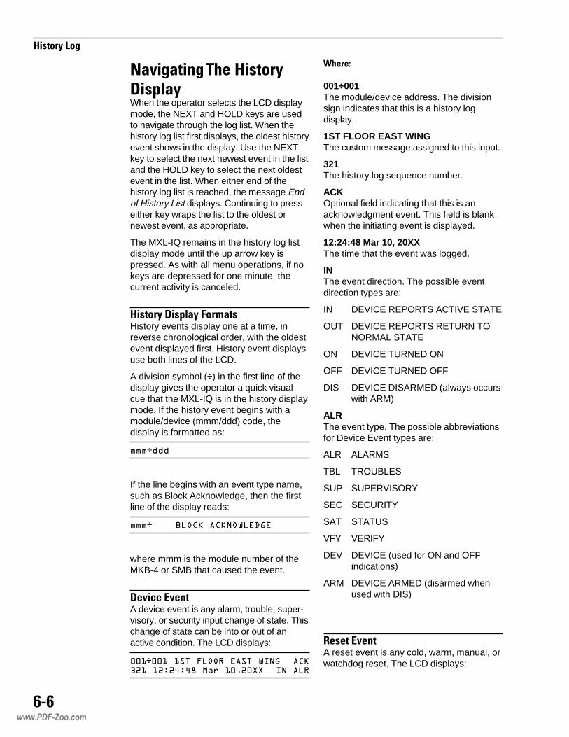
���
���� ����
� 3�� ������������ ���! When the operator selects the LCD displaymode, the NEXT and HOLD keys are usedto navigate through the log list. When thehistory log list first displays, the oldest historyevent shows in the display. Use the NEXTkey to select the next newest event in the listand the HOLD key to select the next oldestevent in the list. When either end of thehistory log list is reached, the message Endof History List displays. Continuing to presseither key wraps the list to the oldest ornewest event, as appropriate.
The MXL-IQ remains in the history log listdisplay mode until the up arrow key ispressed. As with all menu operations, if nokeys are depressed for one minute, thecurrent activity is canceled.
���� ����! �+��� History events display one at a time, inreverse chronological order, with the oldestevent displayed first. History event displaysuse both lines of the LCD.
A division symbol (÷) in the first line of thedisplay gives the operator a quick visualcue that the MXL-IQ is in the history displaymode. If the history event begins with amodule/device (mmm/ddd) code, thedisplay is formatted as:
���÷���
If the line begins with an event type name,such as Block Acknowledge, then the firstline of the display reads:
���÷���������������������
where mmm is the module number of theMKB-4 or SMB that caused the event.
��3�#��(3��A device event is any alarm, trouble, super-visory, or security input change of state. Thischange of state can be into or out of anactive condition. The LCD displays:
���÷����� ��!���"��� ���#�������$%���%&%'&'(�����)%�**��#����"
4����5
001÷001The module/device address. The divisionsign indicates that this is a history logdisplay.
1ST FLOOR EAST WINGThe custom message assigned to this input.
321The history log sequence number.
ACKOptional field indicating that this is anacknowledgment event. This field is blankwhen the initiating event is displayed.
12:24:48 Mar 10, 20XXThe time that the event was logged.
INThe event direction. The possible eventdirection types are:
IN DEVICE REPORTS ACTIVE STATE
OUT DEVICE REPORTS RETURN TONORMAL STATE
ON DEVICE TURNED ON
OFF DEVICE TURNED OFF
DIS DEVICE DISARMED (always occurswith ARM)
ALRThe event type. The possible abbreviationsfor Device Event types are:
ALR ALARMS
TBL TROUBLES
SUP SUPERVISORY
SEC SECURITY
SAT STATUS
VFY VERIFY
DEV DEVICE (used for ON and OFFindications)
ARM DEVICE ARMED (disarmed whenused with DIS)
����(3��A reset event is any cold, warm, manual, orwatchdog reset. The LCD displays:
www.PDF-Zoo.com

��6
���� ����
%+$÷������������"� ����������&%%&�'�����)%�**
4����5
253÷The module address where the resetoccurred. In this example, the watchdogreset originated on the SMB-2 at fixedaddress 253. The division sign indicatesthat this is a history log display.
WATCHDOG RESETThe message describing the type of resetthat occurred. The possible messages forthis field are:
COLD RESETWARM RESETMANUAL RESETWATCHDOG RESET
10100The history log sequence number.
1:22:04 Mar 10,20XXThe time that the event was logged.
��������(3��A set time event records any change to theMXL-IQ real time clock. There are twooccasions when a set time event occurs.They are:
1. When an operator goes into the TESTmenu and manually changes the realtime clock using the SET_TIME function.
2. At the end of a CSG-M configurationupload.
The LCD displays:
%+�÷��� ����#��,�%&��&$������)%�**�������%&��&'+�����)%�**
4����5
251÷The module address where the timechange occurred. In this example, the settime originated from the MKB-4 at address251. The division sign indicates that this isa history log display.
SET TIMEThe message describing this display as aset time event.
10100The history log sequence number.
2:00:30 Mar 10, 20XXThe date and time in the MXL-IQ before theSET TIME function was performed.
2:10:45 Mar 10, 20XXThe time when the event was logged. Notethat this is also the new date and time inthe MXL-IQ as a result of this operation.
'!�#7�.#7��8!�����(3��A block acknowledge event occurs whenthe alarm, trouble, supervisory, or securityacknowledge key is actuated on an MKB-4in a system that allows block acknowledg-ments. The LCD displays:
%+�÷���� �� �����-.��/ ��0��'%�����&%+&�'�����)%�**
4����5
251÷The module address where the blockacknowledge occurred. In this example, theblock acknowledge originated from theMKB-4 at address 251. The division signindicates that this is a history log display.
All Alarms AcknowledgedThe message that describes this displayas an alarm block acknowledge event. Thetext changes to reflect one of the followingfour types of block acknowledgments, asappropriate:
All Alarms AcknowledgedAll Troubles AcknowledgedAll Supervisories AcknowledgedAll Security Acknowledged
4211The history log sequence number.
11:25:14 Mar 11, 20XXThe time that the event was logged.
www.PDF-Zoo.com

��9
���� ����
.$��)!����!��#���(3��This event occurs when the audible silencekey is actuated on an MKB-4. The LCDdisplays:
%+�÷����1�#���� #������'%�%���&%+&�'�����)%�**
4����5
251÷The module address where the audiblesilence occurred. In this example, theaudible silence originated on an MKB-4 ataddress 251. The division sign indicatesthat this is a history log display.
AUDIBLE SILENCEDThe message that describes this event.
4212The history log sequence number.
11:25:14 Mar 11, 20XXThe time that the event was logged.
�3�������(3��This event occurs when an operatoroverrides a verification or confirmation. TheLCD displays:
%+�÷������!#"��#����2�""#��'%�%���&%+&�'�����)%�**
4����5
251÷The module address where the overrideoperation occurred. In this example, theconfirmation override originated on anMKB-4 at address 251. The division signindicates that this is a history log display.
CONFIRMATIONThe feature that is either being overriddenor returned to normal. This selections inthis field are:
CONFIRMATIONVERIFICATION
OVERRIDEThe action that is being applied to thefeature. The selections in this field are:
OVERRIDENORMAL
4212The history log sequence number.
11:25:14 Mar 11, 20XXThe time that the event was logged.
.$��)!�����!��#���(3��This event occurs when the audibleunsilence key is pressed on an MKB-4. TheLCD displays:
%+�÷ ���1�#����1� #������'%�$���&%+&�'�����)%�**
4����5
251÷The module address where the audibleunsilence occurred. In this example, theaudible unsilence originated on an MKB-4at address 251. The division sign indicatesthat this is a history log display.
AUDIBLE UNSILENCEDThe message that describes this event.
4213The history log sequence number.
11:25:14 Mar 11, 20XXThe time that the event was logged.
/ 8����(3��This event occurs when an operator entersa new password at an MKB-4. The LCDdisplays:
%+�÷���3� ��"����2���&��'%�'���&%+&�'�����)%�**
4����5
251÷The module address where the passwordevent occurred. In this example, the
www.PDF-Zoo.com

��:
���� ����
password change originated on an MKB-4at address 251. The division sign indicatesthat this is a history log display.
PASSWORD LEVEL : 1The message that describes this as apassword event and indicates the newpassword authorization level that wasentered.
4214The history log sequence number.
11:25:14 Mar 11, 20XXThe time that the event was logged.
���;��$� ������ �����(3��This event occurs when an operatoruploads a new CSG-M configuration to theMXL-IQ control panel. The LCD displays:
%+'���������0�������-4�0������,5��'%�'���&%+&�'�����)%�**
4����5
254÷The module addres where the configurationchange occurred. In this example, theconfiguration change originated from thefield programmer at address 254. Thedivision sign indicates that this is a historylog display.
Configuration changedThe message that describes this as aconfiguration change event.
10The old configuration modification se-quence number.
11The new configuration modification se-quence number.
Note: These values may not be consecu-tive. They depend on the number of modifi-cations made to the configuration by theCSG-M.
4214The history log sequence number.
11:25:14 Mar 11, 20XXThe time that the event was logged.
� �$ !������3� ����(3��A sensitivity set event displays any changeof sensitivity to a detector device that wasmade manually at a system control panel.The LCD displays:
���÷����� ��!���"��� ���#���������"��$%���%&%'&'(�����)�66+
4����5
001÷001The module/device address. The divisionsign indicates that this is a history logdisplay.
1ST FLOOR EAST WINGThe custom message assigned to this input.
321The history log sequence number.
12:24:48 Mar 10, 20XXThe time that the event was logged.
NORMALThe sensitivity value sent to the device. Theselectable values include:
Hi_3Hi_2Hi_1NORMALLow_1Low_2Low_3
.$�������3� ����(3��A sensitivity set event displays any changeof sensitivity to a detector device made bythe auto sensitivity adjustment system. TheLCD displays:
���÷����� ��!���"��� ���#�������%7�%�8$%���%&%'&$(�����)�%�**
4����5
001÷001The module/device address. The divisionsign indicates that this is a history logdisplay.
1ST FLOOR EAST WINGThe custom message assigned to thisinput.
www.PDF-Zoo.com

���<
���� ����
321The history log sequence number.
2.12Indicates that this is an IEC (Enviro-Link)set sensitivity event. The detector sensitivityhas been set to 2.12 volts. (The voltage canrange from 0-5 volts.) This field maycontain the word CLEAN to indicate thatthis detector was cleaned and restored toits base sensitivity.
+This symbol represents the type of auto-matic correction that was made. A plus sign(+) indicates that the sensitivity was in-creased, a minus sign (-) indicates that thesensitivity was decreased.
12:24:48 Mar 10, 20XXThe time that the event was logged.
����#������3� ����(3��A sensitivity set event displays any changeof sensitivity to a device made by outputlogic. The LCD displays:
!����%÷� ������9��������:�� �0�-$%���%&%'&'(�����)%�**������"��
4����5
FN0012÷The label of the logical function that gener-ated this sensitivity set. The division signindicates that this is a history log display.
SENSITIVITY SET BY LOGICThe message describing this as a logicsensitivity set event.
321The history log sequence number.
12:24:48 Mar 10, 20XXThe time that the event was logged.
NORMALThe sensitivity value sent to the device.
Hi_3Hi_2Hi_1NORMALLow_1Low_2Low_3
���� �/����+��� �.�����=���-�/ ��!The history printout format available at theMXL-IQ control panel appears in the sameformat as all other listing type reports. Thelisting output is in the higher characterdensity mode of the output device. Thevertical pitch varies to clearly distinguishone event from another. If the target printerhas variable point spacing, each event isseparated by a 0.5 line gap. On printerswithout variable point spacing, there is onefull blank line between events.
To interrupt the listing operation at anytime, press the CLEAR key. Significantsystem activities, such as alarms, troubles,etc., automatically terminate the listing. Theprintout always indicates when the listinghas been prematurely terminated.
(Refer to the History Log Sample Print-out on the following page)The basic format of the history printout is:
<Listing Date>
<Listing Conditions>
<Event Type [Modifier]><Event Locator><Event Time><Event Sequence #><Event Description>
•
• (repeated for each event havingmatching conditions)
•
<Listing Terminator>
4����5
Listing DateIdentifies the report type (in this case thehistory log) and the date that the report wasgenerated.
Listing ConditionsShows the filter and starting date for thisreport.
www.PDF-Zoo.com
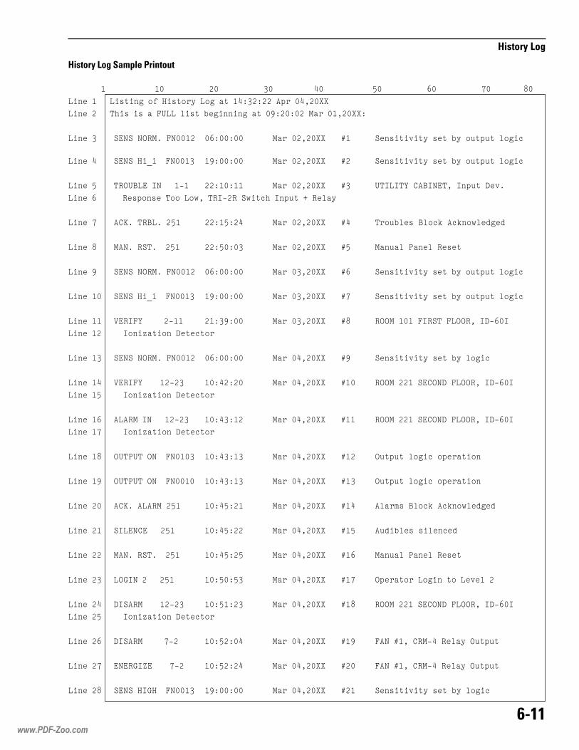
����
���� ����
�������������������������������������������������������������������������������������������������������������
�� ����������� ����������������������������������������
�� ����������������� ���!����"��� � ������#�������$�����������
�� ��� %&'%�'()$*��'���� �������� $���������� +� %� ����,��������"���-��-��!���.
�� ��� %&'%���/����'���� �#������ $���������� +� %� ����,��������"���-��-��!���.
�� ��� �)( 0�&�1'����2� �������� $���������� +� �1�1�3�4�01'&���1 �-��5�,*
�� ���������)���� ���������6���)12�)�%6��.��1 �-��7�)�!��
�� �� �48*��)0�*���� �������� $���������� +� ���-"!���0!�.9��.9 �6!�:��:
�� �� $�'*�)%�*����� �������� $���������� +� $� -�!�;� �!�)����
�� ��# %&'%�'()$*��'���� �������� $���������� +� %� ����,��������"���-��-��!���.
�� ���� %&'%���/����'���� �#������ $���������� + %� ����,��������"���-��-��!���.
�� ���� <&)1�3������2�� ����#��� $���������� + )(($������1)%����(()��152��1
�� ���������1� �=���� �5���.���
�� ���� %&'%�'()$*��'���� �������� $���������� +# %� ����,��������"��!���.
�� ���� <&)1�3������2�� �������� $���������� +�� )(($�����%&4('5���(()��152��1
�� ���������1� �=���� �5���.���
�� ���� ���)$�1'�����2�� �������� $���������� +�� )(($�����%&4('5���(()��152��1
�� ��������1� �=���� �5���.���
�� ��� ( �; ��('���'���� �������� $���������� +�� (-��-��!���.���������
�� ���# ( �; ��('���'���� �������� $���������� +�� (-��-��!���.���������
�� ���� �48*����)$���� �������� $���������� +�� �!��>��0!�.9��.9 �6!�:��:
�� ���� %1�&'4&������ �������� $���������� +�� �-:�"!�����!� .�:
�� ���� $�'*�)%�*����� �������� $���������� +�� $� -�!�;� �!�)����
�� ���� �(?1'�������� �������� $���������� +� (������������ ������,�!��
�� ���� 51%�)$������2�� �������� $���������� +� )(($�����%&4('5���(()��152��1
�� ���������1� �=���� �5���.���
�� ���� 51%�)$�����2� �������� $���������� +�# ��'�+���4)$2��)�!���(-��-�
�� ��� &'&)?1@&����2� �������� $���������� +�� ��'�+���4)$2��)�!���(-��-�
�� ��� %&'%��1?����'���� �#������ $���������� +�� %� ����,��������"��!���.
���� ������ ��!��/����$
www.PDF-Zoo.com

����
���� ����
Event TypeIdentifies the type of history event that isbeing reported. The following event typesare arranged in groups. The modifier fieldsfor each group are different.
Group 1 types:ACK. ALARM Alarm block acknowledge
ACK. TRBL. Trouble block acknowledge
ACK. SEC. Security block acknowl-edge
ACK. SUP. Supervisory block acknowl-edge
MAN. RST. Manual reset via MKB-4
COLD RST. Hard reset from power off
WARM RST. Hard reset via reset jumper
WDOG RST. Hard reset via 6805watchdog
VERIFY Alarm verify
ENERGIZE Energize an output
DE-ENERGIZE De-energize an output
ARM Arm a device
DIS-ARM Disarm a device
SILENCE Silence audibles
UNSILENCE Unsilence audibles
CONFIG. (CSG-M) Configurationchanged
Group 2 types:ALARM Alarm causing device
event
TROUBLE Trouble causing deviceevent
SECURTY Security causing deviceevent
SUPERVS Supervisory causing deviceevent
Group 3 types:SENS Sensitivity set
Group 4 types:LOGIN Operator login
Group 5 types:OUTPUT Output logic event
ModifierThe modifier is an optional field thatextends the meaning of the event type. Forexample, ALARM IN, where IN explains theALARM type.
Group 1 type:No modifiers for this group
Group 2 types:IN Condition now activeOUT Condition now inactiveACK Condition now acknowledged
Group 3 types:Hi_3Hi_2Hi_1NORMALLow_1Low_2Low_3
Group 4 types:0 Lowest access123 Highest access
Group 5 types:
ON Condition now active
OFF Condition now inactive
Event LocatorThis field locates the source or destination
www.PDF-Zoo.com
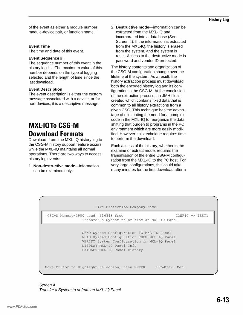
���"
���� ����
of the event as either a module number,module-device pair, or function name.
Event TimeThe time and date of this event.
Event Sequence #The sequence number of this event in thehistory log list. The maximum value of thisnumber depends on the type of loggingselected and the length of time since thelast download.
Event DescriptionThe event description is either the custommessage associated with a device, or fornon-devices, it is a descriptive message.
�=���-�����������8�!� ��+��� Download from the MXL-IQ history log tothe CSG-M history support feature occurswhile the MXL-IQ maintains all normaloperations. There are two ways to accesshistory log events:
1. Non-destructive mode—informationcan be examined only.
2. Destructive mode—information can beextracted from the MXL-IQ andincorporated into a data base (SeeScreen 4). If the information is extractedfrom the MXL-IQ, the history is erasedfrom the system, and the system isreset. Access to the destructive mode ispassword and vendor ID protected.
The history contents and organization ofthe CSG-M configuration change over thelifetime of the system. As a result, thehistory extraction process must downloadboth the encoded history log and its con-figuration in the CSG-M. At the conclusionof the extraction process, an .IMH file iscreated which contains fixed data that iscommon to all history extractions from agiven CSG. This technique has the advan-tage of eliminating the need for a complexcode in the MXL-IQ to reorganize the data,shifting that burden to programs in the PCenvironment which are more easily modi-fied. However, this technique requires timeto perform the download.
Each access of the history, whether in theexamine or extract mode, requires thetransmission of the entire CSG-M configu-ration from the MXL-IQ to the PC host. Forvery large configurations, this could takemany minutes for the first download after a
Screen 4Transfer a System to or from an MXL-IQ Panel
Fire Protection Company Name
CSG-M Memory=2900 used, 316848 free CONFIG => TEST1 Transfer a System to or from an MXL-IQ Panel
SEND System Configuration TO MXL-IQ Panel READ System Configuration FROM MXL-IQ Panel VERIFY System Configuration in MXL-IQ Panel DISPLAY MXL-IQ Panel Info EXTRACT MXL-IQ Panel History
Move Cursor to Highlight Selection, then ENTER ESC=Prev. Menu
www.PDF-Zoo.com
���%
���� ����
configuration is changed. If the .IMH file ispresent after the first download of a con-figuration, the operation will run morequickly on subsequent downloads.
���� ���8�!� ����>$��#�The download process uses the existingcapabilities of the CSG-M programmingsystem. The sequence for extracting historylog events is as follows:
1. PC contacts the MXL-IQ and requeststhe configuration header and data areapointers.
2. If the PC determines that there is historydata present, then the extraction processbegins.
3. The PC computes the required amountof storage and determines if the media inthe PC has enough room for it. If there issufficient room, the process continues; if
not, the user is prompted to changedisks.
4. The PC creates a raw data file thatcontains an identifying header.
5. The PC downloads the compressedhistory log data and appends it to the file.
6. The PC downloads the configurationdata and appends it to the file.
7. The resulting file is closed and thentested for integrity. Any irregularity in thisvalidation ends the extraction processand signals the user.
8. If this is a non-destructive download,then the process is complete.
If this is a destructive download, thenthe clearing of the history log in theMXL-IQ begins. A warm reset occurs inthe MXL-IQ at the end of the extractionprocess.
www.PDF-Zoo.com

���������������� Supervisory 30 VDC peak
66mA max
Alarm 30 VDC peak66mA max
(60 devices in alarm)
���������� �������� ���
ALD-2I Wiring
�����
�� ��� ������� ����� �� ��� ��� ����
�� ������� ��� ���� �! �"#�
$� �%&���� ������%�'� ��� (�� ��%��
)� �%&���� '%�%'��%�'� ��)*� +�����, �� %�� - �����!*� +�����, �� %�� '(%�������!*� +�����- �� %�� '(%�����
.� �%'( ����'�� � /��� 0����'���1 ��2����� %�3��� '��'��� 0�(���3��%���' 0�&������� ��'���� �� '������ ������� ����/4�(������ '%+�� ��(��'�����1 �0 ��������� +4�'%� +������/ '����
�� � ��� 0 ���� ��5�'���2������
�� ����%��� �� 0���'�0��%�'� ��(��4�� ��
!� ����%��� �� 0���'�0��%�'� ��(��4�� )�
6� ���(�� �� �%4 +� ������%�� � � 7�
��� �� ��5�'�� �%&���� ������
��� �3�%����/ �� ���%���� � ��%�� �����
��� 7�( '��'���� %�������5�����
All wiring must be in accordance withArticle 760 of NEC and the local buildingcodes.
Only the devices listed in Appendix A,Table 2 - Analog Addressable Detec-tors on page A-1 may be used. The ULidentifiers for compatibility are the same asthe model names specified.
��� ��� !�
��� ���� � %�� ���
���
������������ �������� ���
www.PDF-Zoo.com

���
����������������������
www.PDF-Zoo.com

���������������� Supervisory or Alarm
5 VDC, 96mA max
������������ ��������� ��
�����
�� ��� ������������ ������������������������ ����������� ������������ ��������������
�� ��� ������ � ������������ ����� !��"������ ������ ����� ������
"� ��� ������������� �������������#�
CMI-300 Wiring - Typical Class B (Style 4) Connection
1 2 3 4 1 2 3 4 1 2 3 4
1 2 3 4 1 2 3 4
1 2 3 4
TB
1
TB
1
TB
2
TB
2
LLM-1
MOM-2/4
LLM-1
CXM-1
2-WIRE
18 AWG
CABLE MIN*
* USE 2-WIRE COPPER CABLE, 105 C, 300V, 18 AWG,
SOLID OR STRANDED, MAX 7 STRANDS.
TYPICAL CLASS B (STYLE 4)
CONNECTION
���www.PDF-Zoo.com

���
�����������������������
1 2 3 4 1 2 3 4 1 2 3 4
1 2 3 4 1 2 3 4
1 2 3 4
TB
1
TB
1
TB
2
TB
2
LLM-1
MOM-2/4
LLM-1
CXM-1
CONDITIONED NON-SWITCHED
LEASED TELEPHONE LINE,
600 OHMS IMPEDANCE
TYPICAL CLASS B (STYLE 4)
CONNECTION
R2
R1
560 OHMS,
1/2W, 5%
P/N 140-820366
1 2 3 4 1 2 3 4
1 2 3 4
1 2 3 4
1 2 3 4
1 2 3 4
1 2 3 4
1 2 3 4
1 2 3 4
1 2 3 4
TB
1T
B1
TB
1T
B1
TB
2T
B2
TB
2T
B2
LLM-1
LLM-1
MOM-2/4
LLM-1
LLM-1
CXM-1
TYPICAL CLASS A (STYLE 7)
CONNECTION
*USE 2-WIRE
COPPER CABLE,
105 C, 300V, 18 AWG,
SOLID OR STRANDED,
MAX 7 STRANDS.
TWO 2-WIRE 18 AWG CABLE MIN
600 OHM MAX LINE RESISTANCE
TOTAL PER PAIR
*
�����
�� ��� ������������ ������������������������ ����������� ������������ ��������������
�� ��� ������ � ������������ ����� !��"������ ������ ����� ������
"� ��� ������������� �������������$�
CMI-300 Wiring - Typical Class A (Style 7) Connection
�����
�� ��� ������������ ������������������������ ����������� ������������ ��������������
�� ��� ������ � ������������ ����� !��"������ ������ ����� ������
"� ��� ������������� �������������#�
CMI-300 Wiring - Typical Class B (Style 4) ConnectionUsing Conditioned, Non-Switched Telephone Line
www.PDF-Zoo.com

���������������� 24 VDC15mA (no energized relays)
Add: 18.7mA per energized relay(75mA - all relays energized)
�������������� �����������
���
CRM-4 Relay Wiring
�����
�� ��� �����������������������������������
�� ����� �!��"�#!����$���%���������� �� &����
�� ����������&#������%!"��%�'�����(�%�
)� ��� ���������&#������%�
*� �������� � �� �������"!����$��+%�'�����(�%,�������
�����
�����������������������
��
�����
����������
www.PDF-Zoo.com

���
�������������� ������
www.PDF-Zoo.com

Only the devices listed in CompatibleNotification Appliances, P/N 315-096363 may be used. The UL identifiersfor compatibility are the same as themodel names specified.
NOTIFICATION APPLIANCES(NFPA 72 Local)All wiring must be in accordance withArticle 760 of NEC and the local build-ing codes.
CSM-4 CCSM-4 CCSM-4 CCSM-4 CCSM-4 Connectonnectonnectonnectonnections and Rions and Rions and Rions and Rions and Ratatatatatingsingsingsingsings
7-7
CSM-4 Loop Wiring for Supervised Notification Appliance Circuit
Electrical ratings:Supervisory 24V unfiltered,
full wave rectified12mA max
Alarm 24V unfiltered,full wave rectified1.5A max
NOTES
1. Power limited toNFPA 70 per NEC 760.
2. Minimum wire size:18 AWG.
3. Maximum resistance:3 ohms total.
4. End of line device:2.2K, ½W,P/N 140-820380.
5. Either circuit may bewired Class A or B.
6. Both circuits aresupervised.
7. Polarity shown insupervisory state.
1 2 3 4 5 6 7 8 9 10 11 12 13 14 15 16MOM-4
MOM-2
(TB1, TB2, TB3, or TB4)or
(TB2 or TB4)
+ -
CIRCUIT 2
STYLE Z(CLASS A)
+ -
STYLE Y(CLASS B)
CIRCUIT 1
2.2K, 1/2W
2.2K,1/2W
NO CONNECTION
NOTIFICATIONAPPLIANCES
NO CONNECTION
www.PDF-Zoo.com

���
��������� �������� ���
��������������������������� �!����"All wiring must be in accordance withArticle 760 of NEC and the local buildingcodes.
�!�� #���!�#� ���$Trip Coil 14.5 ohms
Trip Current 220 to 320mADC (momentary)
SupervisoryCurrent 12mA DC
Voltage 24V unfiltered,full wave rectified
���%�%��%�#���&� '�#60 hour standby5 minute alarm
CSM-4 Loop Wiring for Supervised Municipal Tie
�����
�� ��� �� ���������������������
�� ���������������� ���������������������� ����������� ����� �����!�"�������������� ������������������# ������"�����
$� ������ �� �����%�&������
!� '����%�������������(���%�����
�����(����������������% ��� � �"All wiring must be in accordance withArticle 760 of NEC and the local buildingcodes.
When a CSM-4 circuit is used as a LeasedLine trouble output, SW1 and SW2 onswitch S2 must be set. These positionspermit the degrade trouble bus to activatethe trouble line.
�!�� #���!��� ���$24V unfiltered, full wave rectifiedLoad must be a compatible polarityreversal labeled remote stationreceiver unit
�� �����##� 3mA to 9mA, alarm/supervisory
�) �#�!���#��� �#���� ���2K to 5K ohms
���%�%��%�#���&� '�#60 hour standby5 minute alarm
�*������+,-��+�-�+.-#��+�"
#�*������+��#��+�"
www.PDF-Zoo.com

��/
���� ���������������!�"������
"������0���"1���� �������,��-����,.-���!������22,�All wiring must be in accordance withArticle 760 of NEC and the local buildingcodes.
Set all positions of switch S2 to OFF(OPEN).
�����������"�������Solenoids 24 VDC
16.8 watts max700mA max
Supervisory 12mA max
Alarm 800mA max
CSM-4 Leased Line Circuit Wiring
�����
�� ��� ������� ����� �� ��� ��� ����
�� �&����%� ������%�'� �,01, (���
$� 4�( '��'���� %�� �������+�����
)� ��%���2 �(� �������+���2 ��%���
CSM-4 Loop Wiring for use as Releasing Service(per NFPA 12A, NFPA 13, and NFPA 2001)
�����
�� 7���%���6 ���� %���� ��� ��������
�� �%&���� ������%�'� $ (�� ��%��
$� � ��� * ���� ��+�'���8������
)� 4�( '��'���� %�������+���� *� ������2�
1� ��%���2 �( �������+���2 ��%���
���� � �+,-��+�-�+.-����+ �
�������� �+������+ �
���� � �+,-��+�-�+.-����+ �
�������� �+������+ �
noitacilppA ekaM ledoM31APFN rennikS V42,52XBL2VL
noitcA-erP()eguleD
OCSA V42,701A0128T
OCSA V42,701A0128R
OCSA V42,701A0128
A21APFN oryP V42,136289-005
)nolaH(
oryP V42,256682-005
oryP V42,773380-005
oryP V42,929680-005
1002APFN)002-MF(
oryP PXE42-SHCE
www.PDF-Zoo.com

��,2
���� ��
��������
����
�!�"����
��
MXL-IQ Releasing Service Wiring Diagram Using MOM-2 (NFPA 12A, 13, and 2001)
�����
�� 9�� ��2 ������ ������� *�� �(� *����6 �%3��
noitacilppA ekaM ledoM31APFN rennikS V42,52XBL2VL
noitcA-erP()eguleD
OCSA V42,701A0128T
OCSA V42,701A0128R
OCSA V42,701A0128
A21APFN oryP V42,136289-005
)nolaH(
oryP V42,256682-005
oryP V42,773380-005
oryP V42,929680-005
1002APFN)002-MF(
oryP PXE42-SHCE
�� ������� �����+���� *� ���� ��2�
$� ��%���2 �(� �� �����+���2 '�������
)� 7���%���6 '��'���� %�� �� ��� ��������
1� � ���0*0���� ��+�'� ���� � ���0�'���/:���6� �����%���6 '��'�����
�� ��*�6��� ���0) ���0�'���/:���6� '��'���� %�����'��%� ����
�� �%&���� * ) ���� ��� ���0��
!� �%'( ���0� ���� 3� ����� *�� % ���%�%���5�7�0��� ��� �����2�
;� ��� %�� ������� * �� � �(� ���0) � ��� <����=�
www.PDF-Zoo.com
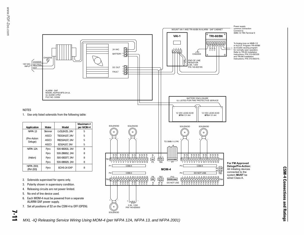
��,,
���� ��
��������
����
�!�"����
��
�����
�� 9�� ��2 ������ ������� *�� �(� *����6 �%3��
noitacilppA ekaM ledoM#mumixaM4-MOMrep
31APFN rennikS V42,52XBL2VL 5
noitcA-erP()eguleD
OCSA V42,701A0128T 5
OCSA V42,701A0128R 5
OCSA V42,701A0128 5
A21APFN oryP V42,136289-005 8
)nolaH(
oryP V42,256682-005 8
oryP V42,773380-005 8
oryP V42,929680-005 8
1002APFN)002-MF(
oryP PXE42-SHCE 8
�� ������� �����+���� *� ���� ��2�
$� ��%���2 �(� �� �����+���2 '�������
)� 7���%���6 '��'���� %�� �� ��� ��������
1� � ��� * ���� ��+�'� �����
�� �%'( ���0) ���� 3� ����� *�� % ���%�%���5�7�0��� ��� �����2�
�� ��� %�� ������� * �� � �(� ���0) � ��� <����=�
MXL -IQ Releasing Service Wiring Using MOM-4 (per NFPA 12A, NFPA 13, and NFPA 2001)
24 VAC
BATTERY +_
+_
+_
DC OUT
FAULT
CHASSIS
CHASSIS
CHASSIS
120 VACINPUT
NEUTRAL
HOT
VAI-1 TRI-60/B6
8 7 6
NC
NC
NC
5 4 3 2 1
+
++
_
__
_
1 2 3 4
MOUNT VAI-1 AND TRI-60/B6 IN ALARM - SAF CABINET
END OF LINERESISTOR3.6K, 1/4WP/N 140-820185
ALARM - SAFMODEL AS/PS5-BFS-24-ULUL GUIDE UTRZFILE NO. S3584
BATTERY ENCLOSUREUL LISTED FOR FIRE PROTECTIVE SERVICE
12 VDC LEAD ACID31 AHBTX-1
12 VDC LEAD ACID31 AHBTX-1
To Analog loop on MMB-1/2or ALD-2I. Program TRI-60/B6as trouble causing programfor normally open operation.Refer to TRI-60 InstallationInstructions, P/N 315-092329and TRI-B6 InstallationInstructions, P/N 315-093315.
Power supplycommon connectionConnect to:SMB-1/2 TB5 Terminal 9
1234
1234
For FM ApprovedDeluge/Pre-Action:
MUST
All initiating devicesconnected to thesystem bewired Class A.
MOM-4
SOLENOID SOLENOIDSOLENOID SOLENOID
TO SMB-1/-2 P6
++ __
+
_ +
_
+
_ +
_
NC
NC
NC
NC
NC
NC
NC
NC
NC
NC
NC
NC
NC
NC
NC
NC
NC
NC
NC
NC
NC
DO NOT USE
CSM-4
CSM-4
CSM-4
NC
1
1 2 1
2
2
1
3 4 5 6 7 8 9 10 11 12 13 14 15 16
NC
NC
NC
NC
NC
NC
NC
NC
NC
NC
NC
NC
NC
NC
NC
NC
NC
NC
NC
NC
NC
NC
NC
NC
NC
NC
NC
NC
NC
NC
NC
NC
NC
NC
NC
NC
1 2 3 4 5 6 7 8 9 10 11 12 13 14 15 16
1
11
2
2
3 4 5 6 7 8 9 10 11 12 13 14 15 16 1 2 3 4 5 6 7 8 9 10 11 12 13 14 15 16
TB4
TB5
TB3
P10
2.2K, 1/2WP/N 140-820830
DO NOT USE
TB7
TB6
P8
P5 P7
P1 P3
P2 P4
TB2
SOLENOID
TB1
www.PDF-Zoo.com

��,�
���� ���������������!�"������
www.PDF-Zoo.com

���������������� Supervisory 18-24.5 VDC
4mA max
Alarm 18-24.5 VDC45mA max
Zone Resistance 35 ohms total
Max Ripple 500mV
������������������ There are three basic connections to theCZM-1B6 as follows:
����������� �������� ���
����
CZM-1B6 Class A (Style D) Wiring CZM-1B6 Class B (Style B) Wiring
���������������The CZM-1B6 supports one zone ofinitiating devices in either Class A (StyleD) or Class B (Style B). The initiatingdevices are connected to terminals 5-8 onthe CZM-1B6 terminal block.
Only the devices listed in Appendix A,Table 1 - Conventional Detectors:Compatible With CZM-1B6 on page A-1may be used. Use up to 15 detectors, anycombination of those listed. Only onePB-1191, and no additional devices, canbe connected to a CZM-1B6. Detectoroperated accessories cannot be used withthe CZM-1B6. The model numbers listedare the UL compatibility identifiers. �����
�� ��� ������� ����� �� ��� ��� ����
�� ������� ��� ���� �! �"#�
$� �%&���� ������%�'� $( )�� ��%��
*� �%') ����'�� � +���, ����'���- ��.�����% �/��� '��'��� ,�)�����%���' ,�&������� ��'���� ��'����� � �����������+0 �)������ '%1����)�� '�����- �,��������� 10 �'%�1������+ '����
(� ��� , ���� ��2�'� *��3- 4"-�5� �*�/!���!!�
�� ���)�� '��'��� �%0 1����� ��%�� � 6��0�� 78� ��%�� 9 6��0�� 98
�� �( ��2�'�� �%&������� '��'����
!� :����%���+ '��'��� �������2�����
1 2 3 4 5 6 7 8 9
+ -
-+
+ -
-+
+ -
-+
EARTH
ANALOG LOOP
POWER
STYLE D(CLASS A)
EOL
+ - - - -+ + +
1 2 3 4 5 6 7 8 9
+ -
-+
+ -
-+
+ -
-+
EARTH
ANALOG LOOP
POWER
STYLE B(CLASS B)
+ - - - -+ + +
EOL
www.PDF-Zoo.com

����
�����������������������
�����
�� ��� ������� ����� �� ��� ��� ����
�� ������� ��� ���� �! �"#�
$� �%&���� ������%�'� ��� )�� ��%��
*� �%&���� '%�%'��%�'� ��*;� 1����� < ��%�� = �����!;� 1����� < ��%�� ')%�������!;� 1����� = ��%�� ')%�����
(� �%') ����'�� � +���, ����'���- ��.����� %�/��� '��'��� ,�)�����%���' ,�&������� ��'���� �� '������ ������� ����+0�)������ '%1�� ��)��'�����- �, ��������� 10�'%� 1������+ '����
�� � ��� , ���� ��2�'���.������
�� ����%��� �� ,���'�,��%�'� ��)��0�� ��
!� ����%��� �� ,���'�,��%�'� ��)��0�� *�
>� ���)�� �� �%0 1� ������%�� � � 9�
��� �� ��2�'�� �%&���� ������
��� �/�%����+ �� ���%���� � ��%�� �����
��� 9�) '��'���� %�������2�����
Analog Loop Wiring
ALD-2I module. The analog loops may bewired Class A (Style 6) or Class B (Style 4).
PB-1191 Installation
�������
When the PBA-1191 is used, the2-position plug from jumper J1must be removed as follows:
• Remove the screw from the centerof the CZM-1B6 plastic cover andplace it to one side.
• Remove the circuit board andlocate jumper J1.
• Remove the 2-position plug from J1.
• Reassemble the circuit board and plasticcover using the screw that was removedin the first step.
• Be sure to use the correct end of linedevice with the CZM-1B6 in this configu-ration.
4 8 8
3 7 7
2 6 6
1 5 5
5 5
4 8 8
3 7 7
2 6 6
1
4 44
3 33
2 22
1 11
4 44
3 33
2 22
1 11
MOM-4TB2
MOM-4TB1
LOOP1
LOOP1
LOOP1
LOOP2
LOOP2
LOOP2
SMB-2
TB2SMB-2
TB3
1
1
1
1
1
1
1
2
2
2
2
2
2
2
3
3
3
3
3
3
3
4
4
4
4
4
4
4
5
5
5
5
5
5
5
6
6
6
6
6
6
6
7
7
7
7
7
7
7
8
8
8
8
8
8
8
CZM-1B6
CZM-1B6
CZM-1B6
CZM-1B6
CZM-1B6
CZM-1B6
CZM-1B6
++
+
-
-
-
ALD-2I
CLASS A INSTALLATION
CLASS B INSTALLATION
See notes 7 and 11.
See note 8.
����!��"�The CZM-1B6 communicates with theMXL-IQ via the MXL-IQ’s analog loops,which may be on the SMB-2 or the optional
www.PDF-Zoo.com

���#
�����������������������
���������$��The CZM-1B6 receives its power from theCZM-1B6 power output on the SMB-2. Thispower is available on TB5 of the SMB-2 onterminals 9-12. The power may be wired as
CZM-1B6 Power Wiring
�����
�� ��� ������� ����� �� ��� ��� ����
�� ������� ��� ���� �! �"#�
$� �%&���� ������%�'� * )�� ��%��
*� � ��� , ���� ��2�'���.������
(� ���'��� �� �����2�����
�� �/�%����+ �� ���%���� � ��%�� �����
�� �� �� ������%�'�-��,�� � �)� ��9/�:���%��%��� :�����'����-�5� $�(/�>(�>��
1
1
1
1
1
1
1
1
2
2
2
2
2
2
2
2
3
3
3
3
3
3
3
3
4
4
4
4
4
4
44
5
5
5
5
5
5
5
5
6
6
6
6
6
6
6
6
7
7
7
7
7
7
7
7
8
8
8
8
8
8
8
8
CZM-1B6
CZM-1B6
CZM-1B6
CZM-1B6
CZM-1B6
CZM-1B6
CZM-1B6
CZM-1B6
++
+
+
-
-
-
-
CLASS A INSTALLATIONSee note 6.
CLASS B INSTALLATION
12
12
11
11
10
10
9
9
SMB-2TB5
Class A or Class B. Since the CZM-1B6monitors the power at its screw terminals, itis possible to T-tap the power connection; thiscan be done only in the Class B configuration.
www.PDF-Zoo.com
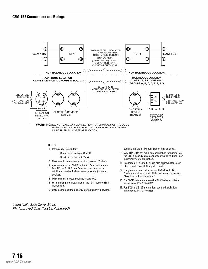
����
�����������������������
�����
�� :�������'%��0 �%,� ������
���� ���'��� ?��%+� �! ?7�
�)�� ���'��� ������� >$��
�� �%&���� �� ������%�'� ���� �� �&'��� $( )���
$� � �%&���� , ��� 7:/$:� :���%��� 7���'��� � �� �,�2� ���� � ���� ��%�� 7���'��� '%� 1� ���� ��%������ � ��')%��'%� 6��/����+0 �����+8 �)����+��2�'���
*� �%&���� �%,� �0���� 2��%+� �� �(� ?���
(� �� ������+ %�� ����%��%��� , �)� :�:/�- ��� �)� :�:/�������'�����
�� ���0 ��')%��'%� 6��/����+0 �����+8 �)����+ ��2�'��
Intrinsically Safe Zone WiringFM Approved Only (Not UL Approved)
��') %� �)� ��/(� �%��%� ��%��� �%0 1� �����
�� ���������7 �� �%@� %�0 '���'��� � ������%� � ,�)� 79/$� 1%��� ��') % '���'��� ��� 2�� ��� �� %���������'%��0 �%,� %����'%����
!� :� %������- ���� %�� ���� %�� %�� %���2�� ,� ��� ����%�� :: %�� ��%�� :::- #���� �- �- %�� #�
>� �� +���%�'� � ����%��%��� ��� ���:5:�� A� ����-B:���%��%��� , :�������'%��0 �%,� :��������� �0����� ����%�� : C%�%���� D'%����E�
��� �� 7:/$:� ��,��%���- ��� �)� 7:/$ ������ ����%��%���������'����- �5� $�(/�!�>*$�
��� �� ���� %�� ���� ��,��%���- ��� �)� ����%��%���������'����- �5� $�(/�!(�(!�
www.PDF-Zoo.com

Electrical ratings:Supervisory 21.7-22.8 VDC
4mA max
Alarm 21.7-22.8 VDC180mA per zone max
Max ripple 400mV
CZM-4 CCZM-4 CCZM-4 CCZM-4 CCZM-4 Connectonnectonnectonnectonnections and Rions and Rions and Rions and Rions and Ratatatatatingsingsingsingsings
7-17
CZM-4 Wiring
NOTES
1. Power limited toNFPA 70 per NEC 760.
2. Minimum wire size:18 AWG.
3. Maximum resistance:70 ohms total(40 ohms if relay basesare used).
4. Each detector or groupof detectors, requires atwo-wire circuit ofthermoplastic fixturewire enclosed inconduit or limitedenergy shielded cablewithout conduit, ifpermitted by localbuilding codes.
5. Loops may be wiredClass A (Style D) orClass B (Style B).
6. 30 devices maximumper loop.
7. All circuits aresupervised.
8. Do not connect morethan one PBA-1191 toeach zone. (Refer toPBA-1191 instruction,P/N 315-095424 forfurther information.)
9. Do not mix smokedetectors with thePBA-1191.
10. The PBA-1191 requiresRev. 3 or higher ofCZM-4 firmware.
Initiating devices per zone:Up to 30 detectors, any combination ofthose listed in Appendix A, Table 1 -Conventional Detectors (except thePBA-1191), on page A-1, may be used.Up to five waterflow switches or 20tamper switches may be used. Wiringmay be Style D (Class A) or Style B(Class B).
1 2 3 4 5 6 7 8 9 10 11 12 13 14 15 16
ZONE 1 ZONE 2 ZONE 3 ZONE 4
STYLE B
(CLASS B)
STYLE D
(CLASS A)
STYLE B
(CLASS B)
+ + + + + + + +- - - - - -
- - -+ + +
- -
+
+
+
MOM-4 TERMINALS
TB1 (UPPER SLOT) OR
TB2 (LOWER SLOT) OR
MOM-2 TERMINAL TB2
EOL
4.7K, 1/4W **
50uF, 50V *
50uF
50V *
50uF 50V *
* EOL CAPACITOR (P/N 100-115588)
** EOL RESISTOR (P/N 140-820188)
PBA-1191
A B C D E F
DO NOT
USE
Linear Beam Detector
www.PDF-Zoo.com

����
���������������������
www.PDF-Zoo.com

�����
����� ��� �����Supervisory 5V ± .5V
140mA
Alarm 5V ± .5V180mA
����� ����������The MOI-7 is shipped with one cable asdescribed below.
��������
The MOI-7 receives its 5 volt power onconnector P1. This power can be sent to othermodules requiring 5 volts from P2. Pin 1 is thepositive input; pin 2 the return. Use thesupplied cable, P/N 600-291261.
����������������������
For Style 4 wiring use only terminals 1 and2 of TB1; terminals 3 and 4 of TB1 are notused. In a Style 4 network, make onlyNetwork A connections and ignore allNetwork B connections. Do not useconnector P5 in this configuration.
������������������� ����� ��� ������ ��
����
!��"�#��
TB2 connects to the return side of thepower supply used with the MOD-16s andMID-16s. There are two positions on theTB2—position 1 connects to the MOD-16/MID-16 and position 2 to SMB-2, TB5-9, orto PS-35, terminal 6.
��$��%� �&���$��%���������
P4 is the connector for the MOD-16/MID-16modules. Connect the first MOD-16/MID-16in the system using a 10-wire cableP/N 555-190940. Be sure that the lockingtab on the cable engages the rib on P4.
www.PDF-Zoo.com

�� '
�����(���$��%(���$��%����������� �&�" ����
CABLE P/N 600-291261TO PSR-1, P9 OR PS-5, J2
STYLE 4
NETWORK A
+5 VDC IN
TB4
P5
P1 P2TB1 TB2
1
1
11
2
22
3
3
4NETWORK
DO NOT USE
DO
NOT
USE
DO
NOT
USE
SEEMOI-7WIRING
MOI-7
RCC-1/1F(PS-5N7)
4
�� ��)��#*�����+#
When terminal 3 of TB3, the local troubleinput, is driven high, it reports a troublecondition to the MXL-IQ. This input isprotected and has a maximum input ratingof 40V. Terminal 2 of TB3 is the commonfor this input.
�� ��� ,+�)��
Terminal 1 of TB3 is used for a local lamptest. When this input is pulled low, theMOD-16 outputs do a lamp test. Use anormally open momentary switch con-nected between terminal 1 and 2 of TB3.
��+#�
The MOI-7 has two inputs. The first inputallows for a local lamp test of all connectedMOD-16 outputs. Screw terminal 1 on TB3is the lamp test input. To activate the lamptest, use a normally open switch betweenterminals 1 and 2 (common) of TB3.
Each MOD-16 board is lamp tested se-quentially. The lamp test sequence stopsautomatically after approximately 30seconds. The second input is for transmis-sion to the MXL-IQ of local trouble. Thisinput is high going for trouble. Each MOI-7transmits the state of this input to theMXL-IQ for annunciation. The MXL-IQindicates this trouble as an MOI-7 localtrouble. See the electrical ratings and wiringdiagrams for these two inputs.
������
�� ������������
�� � ��������������������
�� ������������������������������������
�� �������������������������� !���"��������#�
$� %��������������&'%�( �����&)*�(+ �
+� �������,����-���.��!��
(� �������"������$ ���
MXL-IQ Network Connection Wiring Diagram
www.PDF-Zoo.com

�� �
�����(���$��%(���$��%����������� �&�" ����
MOI-7 Wiring
��$��%
����� ��� �����Supervisory 40V peak
2mA
Alarm 40V peak850mA
Maximum currentfor each output 50mA
��$��%
����� ��� �����Module power 5VDC
2mA max
��+#�� �����
Input voltage range 18-31 VDC
Input impedance 8K ohms
Input current 2mA max
www.PDF-Zoo.com

7-22
MOI-7, MOD-16, MID-16 Connections and Ratings
NOTES
1. 18 AWG minimum forLED and 24V lampconnections.
2. 14 AWG minimum forsupply connections(TB1-9 and 10, TB2-9and 10).
3. All wiring must be inaccordance with NEC760.
4. All wiring mustconform to local codesand to the authorityhaving jurisdiction overthe installation.
5. All wiring to MID-16,MOD-16, or MOI-7(non-network) modulesis unsupervised. Anywiring leaving theenclosure must bewithin 20 feet, in rigidconduit, and must notleave the room.
6. For additionalinformation seeMOI-7 InstallationInstructions,P/N 315-092799.
7. A maximum of 8MOD-16s can be usedwith the MOI-7.
8. Both TB1-9 (or 10) andTB2-9 (or 10) must beconnected to thecommon of the powersupply.
9. When using SR-35,refer to table on thispage. MOD-16 Wiring
1
SW1
SW2
2 3 74 85 96 10
1 2 3 74 85 96 10
TB1
P1 P2
MOD-16
TB2
FROM PREVIOUSMOD-16, MID-16OR MOI-7 (CABLEP/N 555-190940)
TB1, 1-8, PROVIDESCONTROLLED OUTPUTS
S1, 1-8 CONNECT TOCORRESPONDINGOUTPUTS TB1, 1-8
S2, 1-8 CONNECT TOCORRESPONDINGOUTPUTS TB2, 1-8
SEE NOTE 8
NOTE:
TB2, 1-8 PROVIDES ADDITIONALCONTROLLED OUTPUTS
TO COMMON OF SUPPLY OR TB2-10OF PREVIOUS MOD-16 OR MID-16
TO COMMON OF SUPPLY OR TB1-10OF PREVIOUS MOD-16 OR MID-16
TO TB2-9 OF NEXTMOD-16 OR MID-16
CONNECT TO ONE OF THE FOLLOWING:
+
MODULE
SMB-2
MPS-24
PS-35
OR ANY AUXILIARY POWER SUPPLYU.L. LISTED FOR FIRE PROTECTION
SIGNALING USE
TB5-12
TB1-4
TB1-5
TERMINAL
LED
TO TB1-9 OF NEXTMOD-16 OR MID-16
TO NEXTMOD-16 OR MID-16(CABLE P/N 555-190940)
NOTE:
SWITCH S2-8 IS OPEN TOPROVIDE A 2.7K LIMITINGRESISTOR.
THE CABLE P/N 555-190940 ISSUPPLIED. IF THE CONNECTIONIS TO ANOTHER RAIL IN THEENCLOSURE, USE OPTIONALCABLE P/N 555-190941.
1 2 3 4 5 6 7 8
1 2 3 4 5 6 7 8
*eludoM53-RSoTnoitcennoC
61-DOM lanimreTwercS53-RS
1-1BT 4
2-1BT 8
8-1BT 23
ro21-5BT,2-BMS5-1BT,53-SP
33
ro9-5BT,2-BMS6-1BT,53-SP
53
:eesnoitamrofnilanoitiddaroF*)196780-513N/P(snoitcurtsnI53-RS )260580-513N/P(snoitcurtsnI53-SP )139590-513N/P(snoitcurtsnI2-BMS
www.PDF-Zoo.com

7-23
MOI-7, MOD-16, MID-16 Connections and Ratings
1 2 3 74 85 96 10
1 2 3 74 85 96 10
TB1
P41
1
1
10
10
1
10 10
P1
P2
P5P3
MID-16
TB2
FROM PREVIOUSMOD-16, MID-16OR MOI-7 (CABLEP/N 555-190940)
TB1, 1-8, PROVIDESTHE FIRST 8 INPUTS
DO NOT USE
NOTE:
TB2, 1-8 PROVIDESTHE SECOND
8 INPUTS
TO COMMON OF SUPPLY OR TB2-10OF PREVIOUS MOD-16 OR MID-16
TO COMMON OF SUPPLY OR TB1-10OF PREVIOUS MOD-16 OR MID-16
TO TB2-9 OF NEXTMOD-16 OR MID-16
SWITCH
TO TB1-9 OF NEXTMOD-16 OR MID-16
TO NEXTMOD-16 OR MID-16(CABLE P/N 555-190940)
INPUT IMPEDANCE: 8K OHMSMAXIMUM INPUT CURRENT:4mA / INPUT
THE CABLE P/N 555-190940 ISSUPPLIED. IF THE CONNECTIONIS TO ANOTHER RAIL IN THEENCLOSURE, USE OPTIONALCABLE P/N 555-190941.
CONNECT TO ONE OF THE FOLLOWING:
MODULE
SMB-2
MPS-24
PS-35
OR ANY AUXILIARY POWER SUPPLYU.L. LISTED FOR FIRE PROTECTION
SIGNALING USE
TB5-12
TB1-4
TB1-5
TERMINAL
NOTES
1. 18 AWG minimum forall input connections.
2. 14 AWG minimum forsupply connections(TB1-9 and 10, TB2-9and 10).
3. All wiring must bein accordance withNEC 760.
4. All wiring mustconform to localcodes and to theauthority havingjurisdiction over theinstallation.
5. All wiring to MID-16,MOD-16, or MOI-7(non-network)modules isunsupervised. Anywiring leaving theenclosure must bewithin 20 feet, in rigidconduit, and must notleave the room.
6. For additionalinformation seeMOI-7 InstallationInstructions,P/N 315-092799
7. A maximum of 8MID-16s can be usedwith the MOI-7.
8. P1 is connected inparallel with TB1.
9. P2 is connected inparallel with TB2.
MID-16 Wiring
www.PDF-Zoo.com

�� !
�����(���$��%(���$��%����������� �&�" ����
www.PDF-Zoo.com

������������������� �There are two inputs that connect theMOM-2 with the SMB-2. These inputsprovide all the necessary power and datalines to support the optional modules.
The first input is an 8-conductor ribboncable. Attach the cable to P6 on theSMB-2, making sure that the locking rib onthe cable connector engages the lockingtab on P6. Attach the other end of thecable to P7/P10 on the MOM-2, againmaking sure that the locking rib on thecable engages the locking tab on P7/P10.This cable supplies 5 VDC and communi-cation between the SMB-2 and the mod-ules installed in the MOM-2.
The second input feeds 24 VDC full waveunfiltered DC to the MOM-2. This input isconnected to either P5/P8 (SMB-1 only) orTB6/TB7. A 2-wire cable is provided forbackward compatibility with the SMB-1.Connect one end of the cable to P3 on theSMB-1, making sure the cable rib and boardtab lock. Attach the other end of the cableto P5/P8 on the MOM-2 in the same way.The SMB-1 limits this power input to 2amps. Under maximum load conditions theoptional modules must never draw morethan 2 amps from this connection.
When the 24 VDC is provided by theSMB-2 use TB6/TB7 on the MOM-2 toconnect the power. The wire for thisconnection is not supplied (See SMB-2Installation Instructions, P/N 315-095931for terminal connections). Use the follow-ing chart to determine the available 24VDC current.
�������������� �����������
����
Depending on the optional modulesinstalled, additional power may be avail-able at TB5 and for notification appliances.See the table in Appendix D - MXLPower Supply Load Calculations onpage D-2 for the maximum current re-quired by each module under full loadconditions.
Determine which optional plug-in modulesare used in your CSG-M configuration.Depending on the optional modules used,determine the outstanding power by usingthe table in Appendix D - MXL-IQ PowerSupply Load Calculations on page D-2(See the EXAMPLE). This power can beused for notification appliances or for theoptional power connector on TB5.
NOTE: When a CSM-4 is used, you mayadd notification appliances to it if themaximum load current to the MOM-2 doesnot exceed 2 amps (SMB-1); or with anSMB-2, 6 amps (MPS-6/6W) or 12 amps(MPS-12/12W). Include the total alarmcurrent on each CSM-4 notification appliancecircuit when performing the calculations.
STNERRUCDAOLELUDOMMUMIXAM STNERRUCDAOLELUDOMMUMIXAM STNERRUCDAOLELUDOMMUMIXAM STNERRUCDAOLELUDOMMUMIXAM STNERRUCDAOLELUDOMMUMIXAM
ecruoS ecruoS ecruoS ecruoS ecruoS tnerruC.xaM tnerruC.xaM tnerruC.xaM tnerruC.xaM tnerruC.xaM
W6/6-SPMhtiw2-BMS *6
W21/21-SPMhtiw2-BMS *21
2-CANdna1-CAN,rewop6B1-MZCfolatotehtybetareD*
www.PDF-Zoo.com

����
������ ������ ������������
EXAMPLE:
With: one CZM-4 andone CRM-4 andone CSM-4
Total load current =0.720 + 0.075 + 0.034 = 0.83A
With MPS-6/6W:
Remaining Available Current =2.0 - 0.83 = 1.17A (SMB-1)6.0 - 0.83 = 5.17A (SMB-2) with noCZM-1B6 load
With MPS-12/12W:
Remaining Available Current =2.0 - 0.83 = 1.17 (SMB-1)12.0 - 0.83 = 11.17 (SMB-2) with noCZM-1B6 load
www.PDF-Zoo.com

������������������� �There are two inputs that connect theMOM-4 with the SMB-1/-2. These inputsprovide all the necessary power and datalines to support the optional modules.
The first input is an 8-conductor ribboncable. Attach the cable to P6 on theSMB-1/-2 making sure that the locking ribon the cable connector engages thelocking tab on P6. Attach the other end ofthe cable to P7/P10 on the MOM-4, againmaking sure that the locking rib on thecable engages the locking tab on P7/P10.This cable supplies 5 VDC and communi-cation between the SMB-2 and the mod-ules installed in the MOM-4.
The second input feeds 24 VDC full waveunfiltered DC to the MOM-4. This input isconnected to either P5/P8 (SMB-1 only) orTB6/TB7. A 2-wire cable is provided forbackward compatibility with the SMB-1.Connect one end of the cable to P3 on theSMB-1, making sure the cable rib andboard tab lock. Attach the other end of thecable to P5/P8 on the MOM-4 in the sameway. The SMB-1 limits this power input to 2amps. Under maximum load conditions theoptional modules must never draw morethan 2 amps from this connection.
When the 24 VDC is provided by theSMB-2 use TB6/TB7 on the MOM-4 toconnect the power. The wire for thisconnection is not supplied (See SMB-2Installation Instructions, P/N 315-095931for terminal connections). Use the follow-ing chart to determine the available 24VDC current.
�������������� �����������
����
Depending on the optional modulesinstalled, additional power may be avail-able at TB5 and for notification appliances.See the table in Appendix D - MXLPower Supply Load Calculations onpage D-2 for the maximum current re-quired by each module under full loadconditions.
Determine which optional plug-in modulesare used in your CSG-M configuration.Depending on the optional modules used,determine the outstanding power by usingthe table in Appendix D - MXL PowerSupply Load Calculations on page D-2.(See the EXAMPLE). This power can beused for notification appliances or for theoptional power connector on TB5.
NOTE: When a CSM-4 is used, you mayadd notification appliances to it if themaximum load current to the MOM-4 doesnot exceed 2 amps (SMB-1); or with anSMB-2, 6 amps (MPS-6/6W) or 12 amps(MPS-12/12W). Include the total alarmcurrent on each CSM-4 notification appliancecircuit when performing the calculations.
STNERRUCDAOLELUDOMMUMIXAM STNERRUCDAOLELUDOMMUMIXAM STNERRUCDAOLELUDOMMUMIXAM STNERRUCDAOLELUDOMMUMIXAM STNERRUCDAOLELUDOMMUMIXAM
ecruoS ecruoS ecruoS ecruoS ecruoS tnerruC.xaM tnerruC.xaM tnerruC.xaM tnerruC.xaM tnerruC.xaM
W6/6-SPMhtiw2-BMS *6
W21/21-SPMhtiw2-BMS *21
2-CANdna1-CAN,rewop6B1-MZCfolatotehtybetareD*
www.PDF-Zoo.com
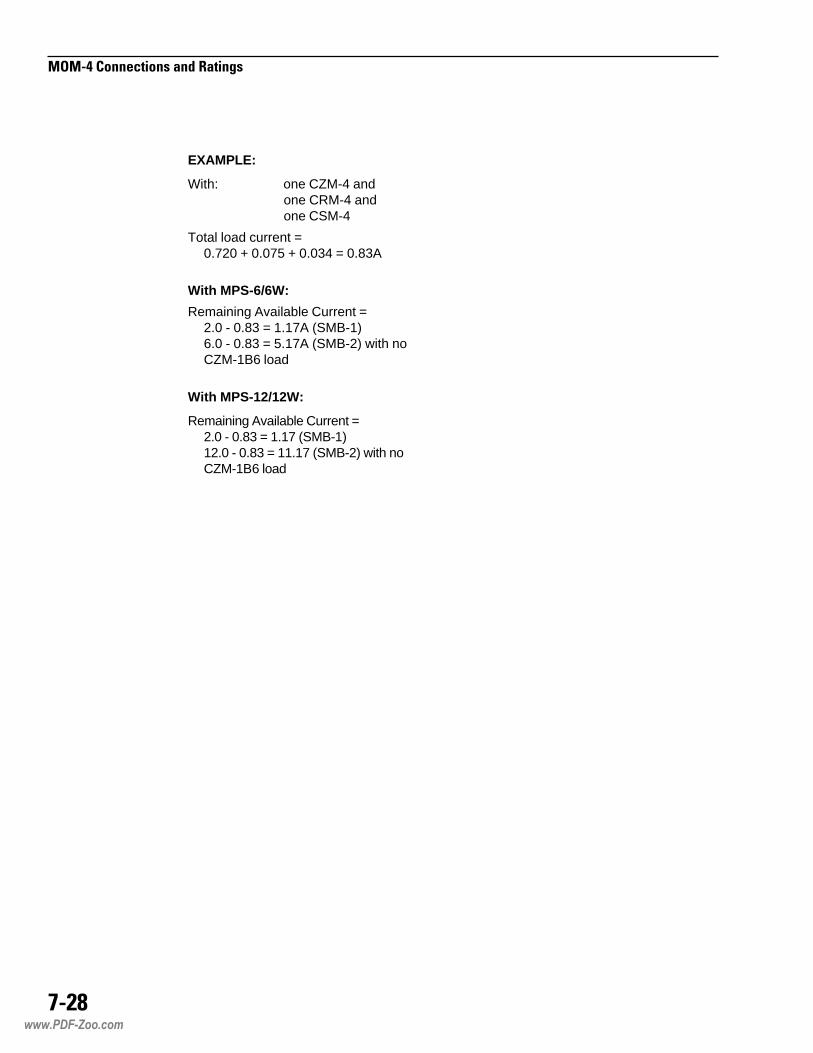
����
������ ������ ������������
EXAMPLE:
With: one CZM-4 andone CRM-4 andone CSM-4
Total load current =0.720 + 0.075 + 0.034 = 0.83A
With MPS-6/6W:
Remaining Available Current =2.0 - 0.83 = 1.17A (SMB-1)6.0 - 0.83 = 5.17A (SMB-2) with noCZM-1B6 load
With MPS-12/12W:
Remaining Available Current =2.0 - 0.83 = 1.17 (SMB-1)12.0 - 0.83 = 11.17 (SMB-2) with noCZM-1B6 load
www.PDF-Zoo.com

MOM-2/-4 MOM-2/-4 MOM-2/-4
TB3 TB3 TB3
P3 P3 P3
P7 P7 P71 1 12 2 23 3 34 4 45 5 56 6 67 7 78 8 89 9 910 10 1011 11 1112 12 1213 13 1314 14 1415 15 1516 16 161 1 1
NIM-1R NIM-1R NIM-1R
DO NOTUSE
DO NOTUSE
DO NOTUSE
SEEFIGURE 2
SEEFIGURE 2
SEEFIGURE 2
CABLE P/N555-190506
TO SMB-2
CABLE P/N555-190506
TO SMB-2
CABLE P/N555-190506
TO SMB-2
EOLR120 OHMS, 1/4WP/N 140-820150
EOLR120 OHMS, 1/4WP/N 140-820150
EOLR120 OHMS, 1/4WP/N 140-820150
EOLR120 OHMS, 1/4WP/N 140-820150
INSTALLED IN MXL-IQ PANEL 1 INSTALLED IN MXL-IQ PANEL 2 INSTALLED IN MXL-IQ PANEL 3
DO NOT USETB1, 1-16
DO NOT USETB1, 1-16
DO NOT USETB1, 1-16
NETWORK PAIR B
SUPERVISED (OMIT FOR STYLE 4)
*
NETWORK PAIR ASUPERVISED
* REQUIRED IN CANADIAN INSTALLATIONS
���������������� 5 VDC, 160mA
For battery calculations, theNIM-1R draws 70mA from 24 VDC.
�������������Up to 32 MXL-IQ Systems can be con-nected in the network with an NIM-1Rinstalled in each MXL-IQ System. For thehighest level of fault protection, install theNIM-1R in the enclosure with the SMB-2,although this is not necessary. Whenconnecting more than 32 MXL-IQ Systems,a REP-1/D2300CP repeater is required.Refer to the REP-1 Installation Instructions,P/N 315-092686 or the D2300CP Installa-tion Instructions, P/N 315-092882, for thewiring diagram.
���������� �������� ���
����
The network can be installed as either Style4 or Style 7. Style 7 is required in Canada.
Each NIM-1R is shipped with two 120 ohmEOLRs—only two are required for eachnetwork pair. Install an EOLR at the ends ofeach network pair. Do not install an EOLR ateach NIM-1R. (For a simple rule of thumb,an EOLR must be installed where only asingle wire lands on a screw terminal.)
Do not T-tap the network wiring. If T-tappingis required, use the REP-1/D2300CPrepeater. Refer to the REP-1 InstallationInstructions, P/N 315-092686 or theD2300CP Installation Instructions, P/N 315-092882, for the wiring diagram. For Style 4wiring, terminate the secondary networkpair (terminals 3 and 4) on each NIM-1Rwith an EOLR.
�����
�� ��� ������� ����� �� ��� ��� ����
�� ������� ��� ���� �! �"#�
$� �%&���� ������%�'� !� (�� ��� �%���
)� *�� ������ �%�� ��(������ ������ �%���
+� ������%�� �(� �(������,- %� �.,/01�%��� ��
�� �%&���� 2��%3� !4 �/��
�� �%&���� '������ �+����
!� �� ��5�� ) ��� %������6 �%�� 7'���'�����
8� 9 �� ��� ������%���� / �� �: ��� �� ��'���'����
NIM-1R Network Wiring (Figure 1)
www.PDF-Zoo.com

����
����������������������
���������������������� The RS-232 interface connects to the NCCwith a 9-pin female D-SUB connector.
Observe the following restrictions:
• Give the NCC a panel number. (Thispanel number is in addition to the panelnumber for the MXL-IQ system that theNCC connects to.)
• The total number of panels in the net-work must not exceed 64, including theNCC.
• For NIM-1Rs that are not connected toan NCC, leave terminals 12–16 discon-nected.
NIM-1R and NCC Wiring (Figure 2)
�����
�� ��� ������� ����� �� ��� ��� ����
�� ������� ��� ���� �! �"#�
$� �%&���� '%;�� ���3�(�+ :����
)� �%;�� ���� ;� �� ��3��'����� %�� '%� ����%2� �(� ���
+� �(������ '%;�� �� ����'��������
�� �%&���� 2��%3� �)4 ��%6 � ��%6�
�� �%&���� '������ ���� ��� '��'����
MOM-4
TB3
TB4
TB1
P1 P3
P2 P4
TB2
P7
1 2 3 4 5 6 7 8 9 10 11 12 14 15 16
1 2 3 4 5 6 7 8 9 10 11 12 14 15 16
1 2 3 4 5 6 7 8 9 10 11 12 14 15 16
1 2 3 4 5 6 7 8 9 10 11 12 14 15 16 1
NIM-1R
DO NOT USE DO NOT USE
CABLE P/N 555-190506 TO SMB-2
SEEFIGURE 1
DO NOT USE
DO NOT USE
DO NOT USE
DO NOT USE1
2
3
4
5
6
7
8
9
SUPERVISED
BL
AC
K
WH
ITE
RE
D
GR
EE
N
BR
OW
N
CONNECT TO COM1OF NCC/NCC-G
CABLE P/N 555-193085
DB9 FEMALE
DO NOT USETERMINALS 12-16IF NCC IS NOTCONNECTED
13
13 13
13
www.PDF-Zoo.com

����
����������������������
MOM-4
TB3
TB4
TB1
P1 P3
P2 P4
TB2
P7
1 2 3 4 5 6 7 8 9 10 11 12 14 15 16
1 2 3 4 5 6 7 8 9 10 11 12 14 15 16
1 2 3 4 5 6 7 8 9 10 11 12 14 15 16
1 2 3 4 5 6 7 8 9 10 11 12 14 15 16 1
NIM-1R
DO NOT USE DO NOT USE
CABLE P/N 555-190506 TO SMB-2
EOLR120 OHMS, 1/4WP/N 140-820150
EOLR120 OHMS, 1/4WP/N 140-820150
EOLR120 OHMS, 1/4WP/N 140-820150 +-
SUPERVISED
CONNECT ONLY TOUL EDP OR ETI LISTED
EQUIPMENT
TRANSMIT
RECEIVE
TRANSMIT ENABLE
FOREIGN SYSTEM RS-485 INTERFACE
13
13 13
13
!�����"#��������$����!"� The FSI installs on TB3 or TB4, terminals1 and 2, of the MOM-4/-2 depending onwhere the NIM-1R is installed. Use one ofthe EOLRs provided with the NIM-1R onterminals 1 and 2. This properly terminatesthe FSI. Use the second EOLR on termi-nals 3 and 4. Never use terminals 3 and4 to connect to the FSI. Refer to Figure 3for the polarity of the FSI driver.
If multiple FSI connections are required,up to four NIM-1Rs may be installed in anindividual MXL-IQ System. In networkedsystems each MXL-IQ can support up tofour FSI ports.
For networked systems, each FSI portmust be configured as either local orglobal in the CSG-M. Local FSI portsdisplay information only on the MXL-IQSystem to which they are connected.Global FSI ports display all events in allMXL-IQ Systems. Refer to the CSG-MManual, P/N 315-090381, for furtherinformation.
�����
�� ��� ������� ����� �� ��� ��� ����
�� ������� ��� ���� �! �"#�
$� �%&���� ������%�'� !� (�� ��� �%���
)� *�� ������ �%�� ��(������ ������ �%���
+� ������%�� �(� �(������,- %� �0�/�<��'������
�� �%&���� 2��%3� !4 �/��
�� �%&���� '������ �+����
NIM-1R and FSI Wiring (Figure 3)
www.PDF-Zoo.com

����
����������������������
MOM-4
TB3
P3
P71 2 3 4 5 6 7 8 9 10 11 12 13 14 15 161
NIM-1R
DO NOT USE
DO NOTUSE
DO NOTUSE
CABLE P/N555-190506
TO SMB-2
EOLR120 OHMS, 1/4WP/N 140-820150
EOLR120 OHMS, 1/4WP/N 140-820150
16 1615 1514 1413 1312 1211 1110 109 98 86 65 54 43 32 21 17 7
TB1 TB1
JUMPER SETTINGSLK1 1-2 JUMPEREDLK2 2-3 JUMPEREDLK3 2-3 JUMPERED
JUMPER SETTINGSLK1 1-2 JUMPEREDLK2 2-3 JUMPEREDLK3 2-3 JUMPERED
CON1 CON1CON2 CON2CON3 CON3CON4 CON4
1 1
1 1
1 1
2 2
2 2
2 2
3 3
3 3
LK1
AIC-4Z AIC-4Z
LK1
LK2 LK2
LK3 LK3
TO POWER SUPPLY, TB2 LOAD - TO POWER SUPPLY, TB2 LOAD -
TO POWER SUPPLY, TB2 LOAD + TO POWER SUPPLY, TB2 LOAD +
TO ACC, TB2, TERMINAL 10 TO ACC, TB2, TERMINAL 10
TO ACC, TB2, TERMINAL 9 TO ACC, TB2, TERMINAL 9
SUPERVISED
SINGLEZONE
MULTIZONE
EOLR120 OHMS, 1/4W,P/N 140-820150
TO ACC #28, P4TO ACC #1, P4
TO ACC #29, P4
TO ACC #30, P4
TO ACC #31, P4
CABLE P/N 500-693801
REFER TO THE ANALASER AIR SAMPLING SMOKE DETECTIONMANUAL, P/N 315-092893, FOR CONNECTION OF THE ACC,THE POWER SUPPLY, AND THE ANALASER DETECTOR ANDAIR SAMPLING NETWORK.
%�&%"������$���The AnaLASER interface connects to theMOM-4/-2, TB3 or TB4, terminals 1 and 2,depending on where the NIM-1R isinstalled. Up to 31 AnaLASER detectorscan be connected to a single NIM-1R.
The ACC-1 requires an RS-485 to RS-232converter which mounts in the back of theACC-1 enclosure. The converter modelnumber is AIC-4Z. The AIC-4Z supportsfrom one to four AnaLASER detectors.Refer to the AIC-4Z Installation Instruc-tions, P/N 315-093792, for the mountingand configuration of the converter and theACC-1s.
NIM-1R and AnaLASER Wiring (Figure 4)
�����
�� ��� ������� ����� �� ��� ��� ����
�� ������� ��� ���� �! �"#�
$� �%&���� ������%�'� !� (�� ��� �%���
)� *�� ������ �%�� ��(������ ������ �%���
+� ������%�� �(� �(������,- %� �0�/�<��'������
�� �%&���� 2��%3� !4 �/��
�� �%&���� '������ �+����
Complete wiring of the converter beforeinstalling the ACC-1 in the enclosure.
• Place the end-of-line resistors in thelocations specified in Figure 4 below.
• Install the cable, P/N 500-693801between the converter and the ACC-1.
• Refer to the AnaLASER Air SamplingSmoke Detection Manual, P/N 315-092893, for connection to the AnaLASERdetector and power supply, as well asmechanical mounting of the ACC-1.
www.PDF-Zoo.com

���������������� Supervisory 18-40 VDC
60mA
Alarm 18-40 VDC130mA
������������������ The MXL-IQ Control Panel connects to theSilent Knight Model 5128/5129 Digital FireCommunicator using the Alarm, Trouble,and Supervisory dry contacts on theMXL-IQ Main Board.
Refer to the Silent Knight 5128/5129 FireSlave Communicator Installation Manual,P/N 150805, provided with Silent KnightModel 5128/5129 for dialer instructions.
The Silent Knight Model 5128/5129monitors all System troubles through theMXL-IQ trouble relay. The MXL-IQ delaysthe AC fail trouble signal in accordancewith NFPA and UL requirements.
In NFPA 72 Remote Station, install batter-ies to provide 60 hour standby capacity.For signalling service DACT wire accord-ing to the diagram on the following page.
�������������� ������������
�������������� �������
����
In NFPA 72 Central Station connections,AC fail reporting is delayed. The delay is 6hours (25% of 24 hours) for NFPA Localand Proprietary, and 15 hours (25% of 60hours) for NFPA Municipal Tie and RemoteStation. Only the reporting of the trouble isdelayed.
AC power must be present for a full minutebefore the system switches back to ACpower from the battery.
Using the optional AC monitor input, theSilent Knight Model 5128/5129 monitors ACfail trouble. When the MXL-IQ Systemreports an AC fail trouble, the Silent KnightModel 5128/5129 sends a specific code tothe Central Station that identifies the troubleas AC fail.
www.PDF-Zoo.com

7-34
Silent Knight Model 5128/5129 Connections and Ratings
NOTES
1. TRI-60R/B6R inputmust be programmedin CSG-M as troublecausing.
2. TRI-60R/B6R outputmust be programmedin CSG-M to transferon loss of AC Mains.
3. All wiring supervisedexcept as noted.
4. For Remote Station,provide 60 hourbattery capacity.
MXL-IQ to Silent Knight Model 5128/5129 Wiring Diagram
5 4
P1 - DC POWER
P4
P3 - AC MONITOR(SEE NOTE 2)
RELAY NC
RELAY C
RELAY NO
(RED)
TELCO 1 RING (GREEN)
TELCO 1 TIP (RED)
HOUSE 1 TIP (GRAY)
HOUSE 1 RING (BROWN)
HOUSE 2 RING (BROWN)
HOUSE 2 TIP (GRAY)
TELCO 2 TIP (RED)
TELCO 2 RING (GREEN)
(BLK)
SILENT KNIGHT 5230(PROGRAMMING)
P2 - CHANNEL INPUTS
(GRY)
(YLW)
(VIO)
(ORN)
(BLU)
(RED)
(GRN)
NOT USED
NOT USED
(BRN)
(RED)
(BRN)
(BLK)
(WHT)
SUPERVISED
SUPERVISED
TO RJ31X
TO RJ31X
SILENT KNIGHTMODEL NO. 5128/29
CHASSIS
SMB-2
TRI-B6R
1
1
2
2
3
3
4
4
5
5
6
6
7
8
9
10
11
12
TROUBLE
ALARM
TB4
TB5
CZM-1B6POWER
36
NOT SUPERVISED
+
-
UL LISTEDEOL DEVICE
3.6K, 1/4W(P/N 140-820185)
* UL LISTED
EOL DEVICE4.7K, 1/2W, 5%(P/N 140-820388)
*
*
*
www.PDF-Zoo.com

�������������To complete the SMB-2 internal wiringconnections, follow the steps below, skippingthose that do not apply to your particularMXL-IQ System.
�� ��������������� ���Primary power for the SMB-2 is provided bythe MPS-6/6W or MPS-12/12W. Both ofthese mount in the lower right-hand cornerof the MXL-IQ enclosure. Follow the instruc-tions below for the appropriate power supply.
MPS-6/6W- Install the MPS-6/6W (SeeMPS-6/6W Instructions, P/N 315-090334/W).With the AC mains disconnected, connectthe MPS-6/6W power cable to P1 of theSMB-2. Be sure that the jumper assem-bly is installed in P14 of the SMB-2. Ifthis jumper is not installed, the SMB-2will detect a permanent AC fail orindicate auxiliary power voltage is low.
MPS-12/12W - Install the MPS-12/12W(See MPS-12/12W Instructions, P/N 315-092030/W). Remove and discard the jumperassembly installed in P14 of the SMB-2.Disconnect the AC mains. Connect theMPS-12/12W power cable to P14 of SMB-2.
���������� ��������� ��
����
��������������������� ��The SMB-2 kit includes a battery cable(wiring harness). Use the harness toconnect the 24V backup batteries to P2 ofSMB-2.
��������� ����� �!"������!���#�There are two connections between theSMB-2 and the MOM-4 board.
1. 24V power connection.P3 provides backward compatibility with theSMB-1 and should only be used whenreplacing an SMB-1. P3 is limited to 2amps. The SMB-2 allows the use of eitheran MPS-6/6W or an MPS-12/12W. TB1terminals 4 and 5 supply 24V to the MOM-4with a maximum of 6 amps (MPS-6/6W) or12 amps (MPS-12/12W) available. Thisoutput must be derated by the total currentdrawn from NAC1 (1.5A max), NAC2 (1.5Amax) and the CZM-1B6 power (1A max) onthe SMB-2. Connect TB1, 4 and 5 on theSMB-2 to TB6/TB7, 1 and 2 on the MOM 4.
2. 5V power and the communicationinterface. Connect the 8-wire ribbon cablefrom P7/P10 on the MOM-4 to P6 on theSMB-2.
www.PDF-Zoo.com

7-36
SMB-2 Connections and Ratings
FIELD WIRINGThe screw terminals for the field wiringcircuits are located on the left and rightsides of the SMB-2. They are labeledTB1 through TB5.
The field wiring circuits available are:
• CZM-1B6 power
• Analog device loop 1
• Analog device loop 2
• Notification appliance circuit 1
• Notification appliance circuit 2
• Common alarm relay
• Common trouble relay
• Style 4 RS-485 Network (MNET)
The following sections describe eachcircuit type and give the related instruc-tions. Refer also to the wiring diagrams.
CZM-1B6 powerAuxiliary power is available on TB5,terminals 9 through 12 of the SMB-2.The circuit is power limited per NECArticle 760 and is rated at 1 amp, 18-31VDC.
This power supply is for use with theCZM-1B6 Remote Conventional Zonemodule.
You may connect a maximum of 20CZM-1B6s to this power source.
T-tapped wiring can be used to obtainthe maximum of 20 CZM-1B6s. Each tapcan support a maximum of 10 CZM-1B6s, 4 ohms max. Multiple powerconnections can be used provided youdo not exceed the ratings above (20CZM-1B6s max and 4 ohms per runmax). For example, you could have fourindividual T-tapped power runs, for atotal of 20 devices (6, 4, 3, and 7 CZM-1B6s), each of the four runs not exceeding 4 ohms resistance.
MOM-4 24V Wiring
CZM-1B6 Supervised Auxiliary PowerClass B Wiring
SMB-2
12
11
10
9
TB5
CZM-1B6
CZM-1B6
CZM-1B6
DO NOT
USE
DO NOT
USE
+
_
T-TAPPING
ALLOWED
www.PDF-Zoo.com
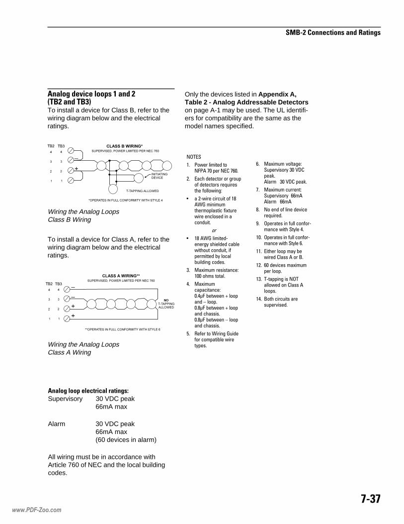
����
%���&�'������ ������!���� �#�
�����#�!�, ���������+���!�&-��&���!����.To install a device for Class B, refer to thewiring diagram below and the electricalratings.
Wiring the Analog LoopsClass A Wiring
Wiring the Analog LoopsClass B Wiring
�����
�� ��� ������� ����� �� ��� ��� ����
�� ���� ������� � ���� �������! ��"����!��� ���#�$
% � �&��� ������� �'�() ��#������������!��� �*������� �#��!�� �# ��#�����
��
% �' �() �������&�#���+ !������� ��,������� �#����- � ��������� ,+ ����,�����#� ���!�
.� /�*���� ��!�!��#��$��� ��! �����
0� /�*������������#��$��01� ,����# 2 ���#� 3 �����'1� ,����# 2 ���#� ���!!�!���'1� ,����# 3 ���#� ���!!�!�
4� 5� �� � (���#� )���� � ������,�� ����+��!�
To install a device for Class A, refer to thewiring diagram below and the electricalratings.
�����#������������ ������� �#�/Supervisory 30 VDC peak
66mA max
Alarm 30 VDC peak66mA max(60 devices in alarm)
All wiring must be in accordance withArticle 760 of NEC and the local buildingcodes.
Only the devices listed in Appendix A,Table 2 - Analog Addressable Detectorson page A-1 may be used. The UL identifi-ers for compatibility are the same as themodel names specified.
�� /�*���� 6�����$�����6�!�+ .� 78����9������ .� 78� ���9�
�� /�*���� �����#�$�����6�!�+ ��������� ����
'� � �#� ��#� ��6�����"������
:� �������! �# ��� �# �&��#�� ��� ��+�� 0�
��� �������! �# ��� �# �&��#�� ��� ��+�� ��
��� ������ �� ��+ ,����� ���!! � � ;�
��� �� ��6���! ��*������� ���
�.� �&�����#� �! �������� # ���!! ���!�
�0� ;�� �������! ���!����6�!���
www.PDF-Zoo.com

����
�������� ����������������
�� ���������������Supervisory 24V, unfiltered
full wave rectified12mA max
Alarm 24V, unfilteredfull wave rectified1.5A max
Only the devices listed in CompatibleNotification Appliances, P/N 315-096363may be used. The UL identifiers forcompatibility are the same as the modelnames specified.
����������� ���The common alarm relay changes statewhenever a fire alarm is detected.
����������� � ���The trouble relay changes state whenevera System trouble is detected.
SMB-2 Relay Wiring
���!��������""����� ��������#��$%&�'�����$%$��(These circuits are for notification appli-ances only, NFPA 72 Local. For NFPA 72Municipal Tie or NFPA 72 Leased Line,use the Model CSM-4.
All wiring must be in accordance withArticle 760 of NEC and local buildingcodes.
�����
�� ��� ������� ����� �� ��� ��� ����
�� ������� ��� ���� �! �"#�
$� �%&���� ������%�'� $ (�� ��%��
)� ��� * ���� ��+�'� ���,- ."-�/� �)�0!��$!��
1� ���(�� '��'��� �%2 3����� ��%�� � � 4�
�� 4�( '��'���� %�������+�����
�� ��%���2 �(� �������+���2 ��%���
�����
�� ���%'� �%���5 ��-$� 67�/��� 6���������+��
�� 8�� ��2 ��( ���������� / ��%�� �'��'�����
$� ���� %�� �����+����(�� ��0����5�����
)� ���%'�� %�� �������+�����
1� ��� ���%2 '��%'�� %���(� �� ���%� ��%���
Notification Appliance Circuits Wiring
�9�84:�
�:�9�
www.PDF-Zoo.com
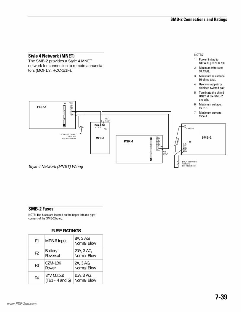
���4
%���&�'������ ������!���� �#�
Style 4 Network (MNET) Wiring
����� ��� �!�! ��� ������ # ��� ����� �� � �#� �������#��! ��� �/;&� ,����
�����
�� ��� ������� ����� �� ��� ��� ����
�� /�#���� ��� !�<�$�' �()�
.� /�*���� ��!�!��#��$'� ��! �����
0� @!� ��!��� ���� �!������� ��!��� �����
4� �����#��� ��� !�������AB �� ��� �/;&����!!�!�
�� /�*���� 6�����$'7 �&��
�� /�*���� �����#�$�4����
%���&�("���
%�������������5�-����.The SMB-2 provides a Style 4 MNETnetwork for connection to remote annuncia-tors (MOI-1/7, RCC-1/1F).
SGNITARESUF
1F tupnI6-SPM ,GA3,A8wolBlamroN
2F yrettaBlasreveR
,GA3,A02wolBlamroN
3F 6B1-MZCrewoP
,GA3,A2wolBlamroN
4F tuptuOV42)5dna4-1BT(
,GA3,A51wolBlamroN
SMB-2
www.PDF-Zoo.com

���6
%���&�'������ ������!���� �#�
www.PDF-Zoo.com

���
��������
���������� ���
�� ������������� �������������������
�� ������������������������������������������������������������������������� �������� !������� ��"����
�� ��������������"����������������������������������������������������������� ������� !�������� ��"����
#� ��������������������������������$�%���&'���(��
� ����������)����������"�����������
*� ���������������������������������)����+,���'*�
-� .�������&'���(�$��������������������"��$�����/��������������+,��#���������� �����
01� 2��3&������������������/��)�����45��6�7"��*������ ���������)���
(� ���������45��6�7"�������� ���������)���
��� 8������+�9����������� ���$�����:+2����������������/�������)�������"������������������������������ ����������������������������
�������������� ���� �
�������� �������������������������� ��������������
����������������
���� ���� ������ ������ ��� ����� �
��������������������������
������ ������� ������
������ ��� ����� �
����� ���������������
�� �� ���� ������ ��� ����� �
� ����� �� � ���� ����� ���� ������
������������������������
����� ���������� ������� ������
������ ��� ����� �
����������������
����������������������
��� �� ������� �� ������ � ����
������ ��� ����� �
��� �� �����!"������������ ���� ���� ������ ������ ��� �
��������������� � �������� ������ � �
2ELBATSECIVEDELBASSERDDAGOLANA
eciveD esaBnoitallatsnIsnoitcurtsnI
6B1-MZC — 2-553590-513
11-TPF/11-PF 8
SR11X-BD,11-BDTPDA-BD+S3-BD
TPDA-BD+SR3X-BDTPDA-BD+06-IBDA
4-129590-513
)d(11-PF 01,8 RPX11/P11-DA 2-956590-513
6B-PCI — 3-603590-513
HI06/I06-DIHAI06/AI06-DI
SR3X-BD,S3-BD 2-782090-513
HB106/BI06-DII3-DA
IRX3-DA4-432390-5134-532390-513
H1/1-ILIHA1/A1-ILI
SR3X-BD,S3-BD 1-783590-513
HB1/B1-ILII3-DA
IRX3-DA4-432390-5134-532390-513
1-TPLI/1-PLI SR3X-BD,S3-BD 5-495290-513
)d(1-TPLIPLI3-DA
PLIRX3-DA4-432390-5134-532390-513
2-PLI 9 SR3X-BD,S3-BD 1-820590-513
)d(2-PLI 01,9 PLI3-DAPLIRX3-DA
4-432390-5134-532390-513
1-TLI S3-BD 1-633390-513
02/01-ISM — 3-309090-513
B02/B01-ISM — 1-923390-513
F6B-ISM — 1-203590-513
6BM-ISM — 1-316390-513
R6/D6/6B-IRT — 3-513390-513
M6B-IRT — 1-745490-513
R/D/S-IRT — 2-242690-513
www.PDF-Zoo.com

���
��������
www.PDF-Zoo.com

���
��������
������������ �����������������������
������� ����������� ��������
������������������� ������
����������������������������������
�� ��� �� ��� ������������
��������������������������������������������������������������
�������������������������������������������������������������
��������������������������������������������������������������
���������������������������������������������������������������
��������������������
�� ��� �� ��� ������������
��������������������������������������������������������������
�������������������������������������������������������������
��������������������������������������������������������������
���������������������������������������������������������������
������
�� ��� �� ��� ������������
��������������������������������������������������������������
��������������������������������������������������������������
���������������������������������������������������������������
���������������������������������������������������������������
������������������
�� ��� �� ��� ������������
��������������������������������������������������������������
��������������������������������������������������������������
���������������������������������������������������������������
���������������������������������������������������������������
���������� !"#�$��
$�%�!&%�''��(�$ #���
�� ��� �� ��� ������������
��������������������������������������������������������������
��������������������������������������������������������������
���������������������������������������������������������������
���������������������������������������������������������������
eciveD etatStupnIegatloV
esnopseR
6B1-MZClamroN
mralAelbuorT
91.4-05.000.5-02.474.0-00.0
531-T06-DI1-TLI
lamroNmralA
elbuorT
00.3-08.100.5-01.397.1-00.0
02/01-ISMlamroN
mralAelbuorT
00.3-08.100.5-01.397.1-00.0
B02/B01-ISMlamroN
mralAelbuorT
00.3-08.100.5-01.397.1-00.0
6BM-ISMlamroN
mralAelbuorT
00.3-08.100.5-01.397.1-00.0
F6B-ISMlamroN
mralAelbuorT
00.3-08.100.5-01.397.1-00.0
IM-SMlamroN
mralAelbuorT
00.3-08.100.5-01.397.1-00.0
R06/D06/06-IRT elbaliavAtoN elbaliavAtoN
R6B/D6B/6B-IRT elbaliavAtoN elbaliavAtoN
M6B-IRT elbaliavAtoN elbaliavAtoN
www.PDF-Zoo.com

���
��������
www.PDF-Zoo.com

���
��������
Battery backup is a requirement for theMXL-IQ. To determine the size battery youmust use, follow the procedures listedbelow. The MXL-IQ can charge a batteryof up to 55 amp hours. A battery sizecalculation form is also provided.
1. Record all the modules required in theform on the following page.
2. Calculate each row across and placethe total in the right column: TotalStandby 24 VDC Module Current
3. Total the right-hand column and recordit at the bottom of the form oppositeTotal System Current.
4. For NFPA 72 Local, 72 Proprietary,and UL 1076 systems multiply the totalsystem current by 24 and record it atthat Total AH location.
or
For NFPA 72 Municipal Tie and 72Remote Station systems multiply thetotal system current by 60 and record itat that Total AH location.
or
For FM Approved Deluge/PreActionsystems multiply the total systemcurrent by 90 and record it at that TotalAH location.
���������� ����������
5. Multiply the AH Total by 1.3 to obtainthe final battery amp hour capacity andrecord it opposite Battery Size.
Three battery models are UL listed for usewith the MXL-IQ:
BP-61—24V, 15 AH
BTX-1—a set of 12V, 31 AH
BTX-2—a set of 12V, 55 AH
Select the battery that meets or exceedsthe final calculated battery amp hour rating.Use an external battery box with the BTX-2model.
www.PDF-Zoo.com

���
��������
�� ���������� �������������������� �������
�� ��������� �����������������������
�� ���� ��������� ����
�!��
!����������"���� ������������#�$%&� ����������������������������� ������������������� ������'
(�()�
(�()#
!�*)�
eludoM ytitnauQCDV42ybdnatStnerruCeludoM
)1etoNeeS(
tiucriCrePtnerruCdaoL
eciveDeniLfodnE tnerruCeciveD42ybdnatSlatoT
eludoMCDVtnerruC
2-BMSAm571
CANrepAm21ecivedrepAm1.1
4-BKM Am5 0 0F1/1-CCR Am57 0 0
04-PST Am07 0 0
4-MSCAm01
0Am21
4-MRCAm51
evitcarepAm51yaler
4-MZCAm55
0Am3
I2-DLAAm501
0ecivedrepAm1.1
003-IMC Am03 0 0R1-MIN Am07 0 AN
7-IOM Am021 0 061-DOM Am2 0 0
61-DIM Am2 0 0
6B1-MZCAm6
Am5AN
6B-PCI Am81 Am5.2 AN1-MIP Am01 0 AN2-MIP )2etoNeeS( 0 AN
1-LAP )2etoNeeS( 0 ANPC0032D Am05 0 0
thginKtneliS Am06 0 0tnerruCmetsySlatoT
=42xHAlatoT-)ylno2-BMM(6701LU,)D27(yrateirporP,)A27(lacoLAPFN=06xHAlatoT-)C27(noitatSetomeR,)B27(eiTlapicinuMAPFN=09xHAlatoT-noitcAerP/eguleDdevorppAMF=3.1x)noitcerroCevreseRmralAhtiw(eziSyrettaB
www.PDF-Zoo.com

���
��������
Each MXL-IQ System enclosure requiresan SMB-2. To ensure that the power supplyis not overloaded, complete the worksheeton the following page.
• Enter the quantity of each module inthe enclosure.
• Calculate both the 24V and 5V loadsfor each row.
• Total the Active 24V and Active 5Vcolumns.
• Ensure that both totals are within thepower supply output ratings in thetable to the right.
����������� ��������������������
���������������� �
������ ������������������������
��� �������������������
����������� ��� ����
������������ ���� ����
www.PDF-Zoo.com
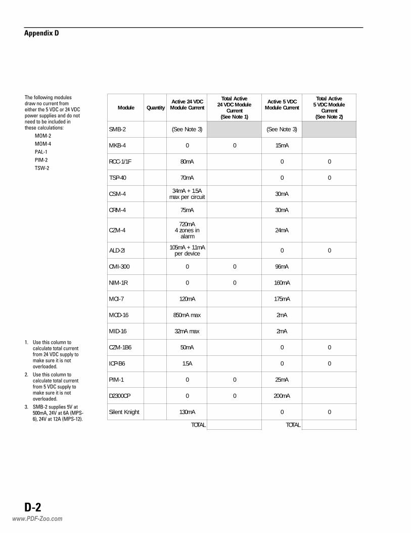
���
��������
�� ���������� ������� ����������� ������������������ ������������� ���������������������
�� ���������� ������� ����������� ����������������� ������������� ���������������������
�� � !"��� ������������##�$%��������&$�' (�"&)%����������$�' (�"��)�
*��������+�,���� ������+���� �������������������������������������+���� ������������������������-���� ������������� ������.
/ "�
/ "�
($0"�
(1 "�
*�2"�
eludoM ytitnauQCDV42evitcA
tnerruCeludoM
evitcAlatoTeludoMCDV42
tnerruC)1etoNeeS(
CDV5evitcAtnerruCeludoM
evitcAlatoTeludoMCDV5
tnerruC)2etoNeeS(
2-BMS )3etoNeeS( )3etoNeeS(
4-BKM 0 0 Am51
F1/1-CCR Am08 0 0
04-PST Am07 0 0
4-MSC A5.1+Am43tiucricrepxam Am03
4-MRC Am57 Am03
4-MZCAm027
nisenoz4mrala
Am42
I2-DLA Am1.1+Am501ecivedrep 0 0
003-IMC 0 0 Am69
R1-MIN 0 0 Am061
7-IOM Am021 Am571
61-DOM xamAm058 Am2
61-DIM xamAm23 Am2
6B1-MZC Am05 0 0
6B-PCI A5.1 0 0
1-MIP 0 0 Am52
PC0032D 0 0 Am002
thginKtneliS Am031 0 0
LATOT LATOT
www.PDF-Zoo.com
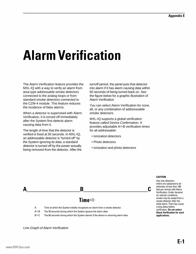
���
��������
The Alarm Verification feature provides theMXL-IQ with a way to verify an alarm fromarea type addressable smoke detectorsconnected to the analog loops or fromstandard smoke detectors connected tothe CZM-4 module. This feature reducesthe incidence of false alarms.
When a detector is supervised with AlarmVerification, it is turned off immediatelyafter the System first detects alarmcausing data from it.
The length of time that the detector isverified is fixed at 50 seconds. In MXL-IQ,an addressable detector is “turned off” bythe System ignoring its data; a standarddetector is turned off by the power actuallybeing removed from the detector. After the
������������ �
turnoff period, the panel puts that detectorinto alarm if it has alarm causing data within60 seconds of being turned back on. Seethe figure below for a graphic illustration ofAlarm Verification
You can select Alarm Verification for none,all, or any combination of addresssablesmoke detectors.
MXL-IQ supports a global verificationfeature called Device Confirmation. Itprovides adjustable A�B verification timesfor all addressable:
• Ionization detectors
• Photo detectors
• Ionization and photo detectors
�� ����
��������������� ������������������������������������������������������������� ������������������������������������������������������������������� ������������������������������������������������������������ �������������������������������������������������������������������������
� ! �
�����
� ������� ��������!������������������ ��"�������������������������������
��# ����$������������� � ��������!������ �����������������
#�% ����&������������� � ��������!���������������������������������� ���������
Line Graph of Alarm Verification
www.PDF-Zoo.com

��"
��������
With Device Confirmation, the B�Cverification time known as System Justi-fied Alarm time is also adjustable. It is thesame time used by both ionization andphoto detectors. If a device is individuallyselected for alarm verification, the alarmverification feature takes priority over thedevice confirmation option. For adjustmentranges, refer to the CSG-M ProgrammingManual, P/N 315-090381.
There is an Override menu selection in theTest menu of MXL-IQ. Select Alr_Verify todisable all alarm verification or selectAlr_Confirm to disable all alarm confirma-tion for a period of up to 4 hours or untilmanually re-enabled.
www.PDF-Zoo.com

���
��������
Envirolink is an optional feature that permitsMXL-IQ to compensate automatically forenvironmental changes (such as dirt and dustbuildup) in the analog voltage of an I Seriesphoto or ion smoke detector. The selection ofEnvirolink devices is made in the CSG-M.
Once a detector is chosen to be covered byEnvirolink, MXL-IQ stores and analyzes theanalog readings of the smoke detector andadjusts the detector’s threshold upward ordownward, as necessary, to maintain aconstant sensitivity.
As the analog voltage increases due toenvironmental factors, an equivalentincrease in the detector’s alarm thresholdprevents factors other than smoke fromcausing an alarm. This method maintainsthe selected detector’s sensitivity.
Typically, the analog voltage changesslowly over long periods of time for environ-mental factors, but changes quickly overshort periods of time for actual smoke.
�� ������ �����������When a new or modified CSG-M is loadedinto a system, the MXL-IQ control panelgoes through an initial system power-up.The MXL-IQ does not keep the Envirolinkoption where it was formerly applied whenthis new system powers up. The Envirolinkmemory re-initializes, and then MXL-IQbegins adjusting the alarm thresholdswherever Envirolink is selected in the newCSG-M.
����������
����� ��� ����������������������������� �!�"�����������After MXL-IQ checks that the actual ID of adevice with Envirolink agrees with theCSG-M, it adjusts the detector’s alarmthreshold according to the data stored. Thefirst adjustment occurs after 100 hours ofdata accumulation. In the case of powercycling or resetting, adjustments beginwithin 90 seconds.
�����
�������� �����
������ �����
�� ��
�#�����$��%$&'��!#
���#''�!#���#�$�(&�"#���'� &"�#�����&��)�# *
www.PDF-Zoo.com

��+
��������
If a detector with Envirolink (IEC) reports analarm condition before the detector’s alarmthreshold is adjusted, the alarm delays untilthe alarm threshold is adjusted. If the devicecontinues to report an alarm condition onceits alarm threshold is adjusted, the alarmreports.
If the CSG-M and the device ID do not agree,the IEC for that device does not activateuntil the trouble condition is removed fromthe system and the panel is reset.
",'��-�������&�When a system is brought on-line, or whenthere is a complete loss of power in anMXL-IQ enclosure containing detectors withIEC applied, the operator must perform areset sequence for the IEC devices in thatMXL-IQ and also reset the MXL-IQ.
When an MXL-IQ is powered the first time,and there is no data for IEC devices, MXL-IQleaves these devices at the default alarmthreshold. However, if former IEC data isavailable, MXL-IQ adjusts the device alarmthreshold accordingly.
&����������� ��� ���.� �����������������Environmental conditions usually cause asmall change in the analog voltage over along period of time. At regular intervalsMXL-IQ collects analog data for eachdetector with IEC and adjusts the alarmthreshold accordingly. MXL-IQ adjusts forboth up and down changes in the analogvoltage. In addition, if system power is lost,MXL-IQ adjusts the alarm thresholds asneeded by using stored data.
���/� ����# �����0��� ��� ���A trouble condition involving the IEC maybe annunciated by the MXL-IQ as:
����������� �� ���������
OR
�������������������������
The trouble conditions shown above areannunciated on a detector-by-detectorbasis as each detector is checked.
MXL-IQ annunciates a trouble condition fora detector when its alarm thresholdreaches a predetermined limit. The opera-tor should acknowledge the trouble, cleanthe detector if possible, and reset thecontrol panel. If the detector is not cleaned,the control panel annunciates this troublecondition after every panel reset until thedetector is cleaned. When it is cleaned, thatis detected by the Auto Clean Detectionfeature.
�� ��� /� ����������1� �/ ��MXL-IQ automatically detects when an IECdetector was cleaned and checks whetherthe detector is considered clean by MXL-IQ’sstandards. If the detector is clean, IEC datafor that device is reset to clean levels, andthe following message prints:
��������������
NOTE: Automatic detection and documen-tation of the cleaning of a detector byMXL-IQ may take as long as 1 hour. Toavoid this, use the Det cleaned option inthe Test menu to avoid automatic cleandetection. When you enter the address ofthe detector that was cleaned, MXL-IQadjusts that detector’s Norm sensitivitysetting reference.
1� �/ ��� ������IEC must be enabled in the CSG-M in orderto have access to the Det_cleaned optionthrough the MXL-IQ Annunciator Panel.
At the Test menu, use the Left or Rightarrow key to cause the D in Det_cleaned tostart blinking:
����� ����������������
Press ENTER when the D is blinking toselect Det_cleaned.
www.PDF-Zoo.com

��2
��������
The System asks you to type the moduleand device numbers.
• Type the three-digit module numberand the three-digit device number(mmm/ddd), including all leadingzeroes.
• Press ENTER.
After entering the module-device, MXL-IQchecks whether the device is subject toIEC. If the device is not subject to IEC, or ifIEC is not enabled for the system, an errormessages displays:
������� ��������� ���
���� ��������������
If the device is an IEC detector, MXL-IQdisplays and prints the time, date, device,and custom message of the cleaneddevice.
www.PDF-Zoo.com

��3
��������
www.PDF-Zoo.com

���
��������
� ��������������������������������������
������� !���"�#
When the Latching/Non-Latching (selfrestoring) trouble option is set to YES in theCSG-M, MXL-IQ automatically removestrouble conditions from the trouble queuewhen the OUT OF TROUBLE condition isdetected.
For NFPA 72 Local, 72 Municipal Tie, and72 Remote Station systems, the followingcriteria must be met in order for the troubleto be removed from the trouble queue:
• Module and device numbersmust be identical
• Trouble type must be identical
• Both IN/OUT conditions must berecorded in the queue
• All printers being used must print bothIN/OUT conditions
When all these conditions are met, the MXL-IQremoves both the in and out occurrence ofthis trouble from the queue. If there are noother events in the system (alarm, supervi-sory, trouble, or security), MXL-IQ returnsto the SYSTEM NORMAL display (withouta system reset). If there are other events inthe system, MXL-IQ updates the display.
������������������� ��������
For NFPA 72 Proprietary systems, thefollowing criteria must be met if the troubleis to be removed from the trouble queue:
• Module and device numbersmust be identical
• Trouble type must be identical
• Both IN/OUT conditions must berecorded in the queue
• All printers being used must print bothIN/OUT conditions
• Both IN and OUT conditions must beacknowledged and printed
When all these conditions are met, MXL-IQremoves both the in and out occurrence ofthis trouble from the queue. If there are noother events in the system (alarm, supervi-sory, trouble, or security), MXL-IQ returnsto the SYSTEM NORMAL display. If thereare other events in the system, MXL-IQupdates the display.
Not all troubles can be removed from thetrouble queue. If there is no OUT conditionreported (i.e., Class A loop trouble), MXL-IQrequires an acknowledgement and reset.
www.PDF-Zoo.com

��$
��������
www.PDF-Zoo.com

H-1
Appendix H
WARNING: These circuits areintended for 24 houralarm monitoring only.
UL 1076 requires a TSW-2 tamper switchas well as a supervised printer (PAL-1/PAL-2). Other supervised printers that areselectable in CSG-M are the TI-820 andthe LA-50.
Only Models TRI-60/-60D/-60R orTRI-B6/-B6D/-B6R may be used assecurity points. A COMMUNICATIONFAILURE with a TRI device configuredfor SECURITY results in a SECURITYALARM as well as a communicationtrouble. When installing a TRI device inthe CSG-M, be sure to set the deviceusage field to security; otherwise, thedevice usage defaults to fire alarm.
IIIIInstnstnstnstnstalling alling alling alling alling AAAAA S S S S Securecurecurecurecurititititityyyyy P P P P Pointointointointoint
CAUTION:• When setting the device address using
the FPI-32, select the normally closedalarm causing input.
• Connect only one switch per TRI input.
For proprietary burglary application(UL 1076):
• Use a TSW-2 tamper switch to monitorthe main enclosure.
• Monitor each TRI-60/-60D/-60R orTRI-B6/-B6D/-B6R related to this applica-tion for 24 hours by using a listed motiondetector (to prevent tampering).
Installing the Security Point for UL 1076
* END OF LINE DEVICE: P/N 140-820185REFER TO ,P/N 315-092329 OR 315-093315, AS APPLICABLE
TRI INSTALLATION INSTRUCTIONS
1 1 1
2 2 2
3 3 3
4 4 4
5 5 5
7 7 7
6 6 6
8 8 8
ANALOGLOOP IN
ANALOGLOOP IN
ANALOGLOOP IN
SWITCH SWITCH SWITCH A
SWITCH B
NC NC NC
NC
+ + ++ + +- - -- - -
ANALOGLOOPOUT
ANALOGLOOPOUT
ANALOGLOOPOUT
EOL *3.6K1/4W
EOL *3.6K1/4W
EOL *3.6K1/4W
EOL *3.6K1/4W
GND GND GND
NOT USED
TRI-60 / TRI-B6 TRI-60R / TRI-B6R TRI-60D / TRI-B6D
NOT USED
www.PDF-Zoo.com

���
��������
www.PDF-Zoo.com

���
��������
Application Specific Detection (ASD)allows the system designer (and anyonewith Control menu access) to program anILP-2 detector’s sensitivity, pre-alarmthreshold, and other alarm-related param-eters using English descriptions of thedetector's environment (application). Thiseliminates the need for detailed knowledgeof smoke detector terminology andoperation. The designer can set all of thecritical detector parameters by simplyselecting an application description thatclosely fits the one where the detector is tobe installed.
For example, to use ASD to select theoptimal parameters for a detector in a hotellobby, select the LOBBY application in theCSG-M for that device. The MXL willautomatically transmit the factory deter-mined sensitivity, pre-alarm threshold, anddetection algorithm (R-algorithm) to thecorresponding device. This eliminates theguesswork of selecting these parametersfor different environments. Changes madeat the control panel using the Control menu(Change_Apps) override the ASD settingsmade in CSG-M for that ILP-2 device untilthe next power-on reset.
��������������� ����������
�����
���������������� ���������
���������������� ����������
���� ���������������� ��������������������
������
���� �������������������������������������������
��������
�� !������������������������
���!��!���������"��������������������#����!��������������
"�� ��������������������������������$�����
���!�����������������
#��� ���������%
�������������$������������&�������������������������������������!��������������������������
������$��
�� ������������������������������������!������������!��������"���$��
�� �������'�����������������$�����!����$������'
������"�
$�# ����(���!� ���������������������������
����)��������
������������*�����+
��������������$�������)����������
������"����������
��#�����������
�$��������������$�,
������������"����������$�������������������$�����-��������
�����������)
��� ������$�,�����'.��������"�����������������������
����)�����������)������
��� ����������������������
����������)���������������������$�����������)�
������
�� ��� ���������������������������� �� �!"������#�$��%&%��%�'�%���%�
�� ��(����)(������������������������������ �� �!"�����*�$��%�&%��%�'�%���%�
#� +����,�-���������'�&.%/0���12,��������������.���������/������/"������.�/���������%�/.���.���&��%�����������/.���������������
www.PDF-Zoo.com

���
��������
����������������Since one of the parameters transmitted tothe detector adjusts the detection algo-rithm (R-algorithm) to reduce false alarms,it is necessary to defeat ASD (or at leastthe R-algorithm) when smoke testing ASDdevices. The Test ASD_Devices menuoption has been supplied for this purpose.When ASD devices are to be smoketested, the Test ASD_Devices option mustbe enabled. This disables the applicationspecific detection R-algorithm so thedetector will alarm using the standard testgas method. If the Test ASD_Devicesoption is not enabled prior to smoking the
device, the tester may find it extremelydifficult to alarm the detector since thealgorithms are designed not to be fooled bya deceptive phenomenon such as test gas.
Once the Test ASD_Devices option hasbeen enabled using the test menu, the testershould wait 3 minutes before attempting totest the ASD devices. This time may varyslightly with the number of ALDs and ASDdetectors in a system. This will ensure thatthe ASD R-algorithm has been defeated fortest purposes. The system will not reset untilthe Test ASD_Devices option has beendisabled.
www.PDF-Zoo.com

���
��������
� ������������� ����� ����������������
���������� ����������
AC Fail or Brownout Primary AC power is missing or below thebrownout level; the System is running onbattery backup.
Airflow Too Low AnaLASER airflow is below programmedthreshold.
Airflow Too High AnaLASER airflow is above programmedthreshold.
AnaLASER Power Trouble Problem with AnaLASER power supply.
ASD Testing Enabled Application specific detector testing isenabled. The applications feature isdisabled during testing.
Aux Pwr Class A Fail Neg The negative side of the CZM-1B6 powercircuit is open.
Aux Pwr Class A Fail Pos The positive side of the CZM-1B6 powercircuit is open.
Battery Backup Invalid A battery is connected, but not selected inCSG-M.
Battery Fuse/Wiring Open Either the battery is not connected, or thebattery fuse is blown, or the battery voltageis too low.
Carrier Lost CMI-300 to CXL communications problemwhere the CMI-300 does not see the CXL'smodem carrier (tone). No data is beingtransmitted.
Class A Loop Trouble If Class A: The initiating circuit at thismodule address has an open.If Class B: Wired zones are missing theClass A jumpers.
� ������������� ����� ����������������
www.PDF-Zoo.com

���
��������
� ������������� ����� ����������������
CMI-300 General Trouble Communications trouble between the CMI-300 and the CXL. Data is attempting totransmit.
CSGM Out Of Date This MXL-IQ (node) will need to be updatedwith the latest CSG-M networked program.A network CSG-M has been loaded onanother MXL-IQ (node) and has a referenceto this MXL-IQ (node).
Daily Detector Test Abnormal Device is defective.
Detector Trouble AnaLASER detector in need of repair.
Device Communication Error An analog device whose response hasfailed error checking.
Device Detected Waveform Error An analog device reports this trouble if itreceives an unknown polling waveform.
Device LED Turned On A device LED was turned on from the Testmenu of the MXL-IQ.
Device Multiple Response Two or more analog devices at the sameaddress have reported during normalsupervision.
Device Out of Calibration This message is used with XLD and is thesame as the XL-3 message,Response out of window at cal.
Device Receive Error An analog device reports this troubleif it receives an incorrect analogtransmission.
Event log 80% full Use extract history in CSG-M to reset theMXL-IQ history log.
Event log 90% full Use extract history in CSG-M to reset theMXL-IQ history log.
Function Recursion Trouble The number of evaluations of output logicrequired until outputs are stable hasexceeded the system maximum. RewriteCSG-M to simplify functions.
Ground Fault Minus Low impedance to the negative side of oneof the field wiring circuits to earth ground.
www.PDF-Zoo.com

���
��������
� ������������� ����� ����������������
Ground Fault Plus Low impedance to the positive side of one ofthe field wiring circuits to earth ground.
High Battery Voltage Battery voltage is too high because batteryhas been overcharged. Battery and/orcharger are possibly defective.
History Manually Turned Off History Log has been manually changedHistory Manually Turned On (Turned Off / Turned On / Erased) usingHistory Manually Erased the MKB.
IEC Limit Reached. Service Req Detector environmental compensation hasreached UL limit. Detector is very dirty andrequires cleaning.
IEC/Pre-alarm Memory Error An unsuccessful attempt was made toaccess the IEC area of flash memory. IsIEC-1 module present? Is segmented flashpresent?
Incorrect Device ID An analog device whose type or usage doesnot agree with the CSG-M assignment atthat address.
Incorrect Node Address Address on NIM-1R is incorrect.
Input Device Not Responding A device assigned in CSG-M is not reportingat its address.
Input Dev Response Too Low Input wiring to TRI or CZM-1B6 moduleshas an open circuit or no EOL. Loss ofpower to CZM-1B6 module. Smoke detectorchamber defective.
Input Device Requires Service An ion or photo detector has exceeded the80% dust threshold.
Input Disarmed An initiating device was disarmed throughthe Control menu.
Keyswitch Activated (CANADA) This is a trouble type for activation ofCanadian manual station keyswitch if noalarm is present.
Lamp Supervision Trouble MID-1 input trouble when used for lampsupervision.
www.PDF-Zoo.com

���
��������
� ������������� ����� ����������������
Log FULL, Events Will Be Lost History Log is full. Use extract history inCSG-M to reset the MXL-IQ history log
Loss of 24V Input Power A CZM-4 has lost its 24 VDC input.
Low Battery Voltage Battery voltage readings low; the batteryrequires recharge/replacement.
Low IEC Voltage, Service Req Defective device.
Memory Error In RAM Test An error was detected in RAM memory IC112 or IC 113.
Memory Error in ROM test An error was detected in the EPROM IC111 or IC 110
Memory Upgrade Required Starting with revision 6.00, the MXL-IQrequires a memory upgrade (RAM) insocket IC113.
Missing Device ID Response An ALD module has not returned an ID Pollresponse for any of its detectors or devices.NOTE: This trouble will accompany modulenot responding for missing ALD modules.
Module Comm Failure When network communications areinterrupted, and then restored, all moduleaddresses affected report this trouble.
Module Not Responding The module assigned in CSG-M at thisaddress is not responding.
Module RAM Failure The CRM-4, CSM-4, or CZM-4 at thisaddress has determined that its internalRAM is not operating properly.
Module ROM Failure The module at this address has a ROMchecksum failure.
MOI-1 Local Trouble This trouble is reported when the TRBL INinput of the MOI-7 is driven high.
MOI-1 Voice System Trouble This condition is caused by driving theTRBL IN of the MOI-7 high with voicemodules configured in CSG-M for thismodule.
www.PDF-Zoo.com

���
��������
� ������������� ����� ����������������
MOI-1 Zone Disarmed Output of an MOI-7 (MOD-16 or VPM-5)has been disarmed at the MXL.
More Than 60 Alarms The System alarm queue is full, and morealarms have been received.
More Than 60 Securities The System security condition queue isfull, and more security conditions havebeen received.
More Than 60 Supervisory The System supervisory queue is full, andmor supervisories have been received.
More Than 60 Troubles The System trouble queue is full, andmore supervisories have ben received.
Multiple Module Response Two or more modules respond at thesame address.
Multiple Response Analog Poll Two or more analog devices at the sameaddress have reported during an analogdata request.
MXL Network Failure The MKB/RCC has lost communicationwith the MNET.
Network CSGM Upload Needed A function was added to an XNET nodeand had a reference to another node. Thisfunction shall be added to each node itreferences.
Network Input Disarmed A point on another XNET node has beendisarmed.
Network Loop A Failure The Style 7 primary (A) RS485 MNETnetwork loop has failed.
Network Loop B Failure The Style 7 secondary (B) RS485 MNETnetwork loop has failed.
No CSG - Default In Use No CSG-M custom programming wasfound in FLASH memory so the system isusing the default CSG-M.
Node Disconnected XNET node was logically disconnectedfrom the NCC.
Node Multiple Response Two nodes are programmed at the sameaddress.
www.PDF-Zoo.com

���
��������
� ������������� ����� ����������������
Node Not Responding XNET wiring and/or NIM-1R module isdefective.
Out of RAM Call Pyrotronics The configuration upload is too large.
Out of Tasks Call Pyrotronics Contact the Siemens Building Technolo-gies, Inc. Technical Services Department.
Output Disarmed Indicates that an output point has beenmanually disarmed.
PRE 1 Level AnaLASER device has reached itspre-alarm setting.
Pre-alarm Device has reached its pre-alarm setting.
Pre-dirty Analog Volt. Reached IEC compensation has reached a levelwhere the detector should be cleaned.
Printer Off Line/Fault A supervised printer is not responding.
Printer Out Of Paper The printer has run out of paper.
Relay Coil Open The relay coil at this address is open.
Relay Disarmed The relay at this address has been dis-armed from the Control menu.
Relay Driver Inoperative The relay on the CRM-4 or CSM-4 at thisaddress does not operate when com-manded to energize.
Relay Supervision Failure The relay at this address has a coil failure.
ROM SW Version Error Module at the address noted needs anupdate to latest available software level.
Signal Circuit Disarmed The NAC at this address was disarmedfrom the Control panel.
Signal Circuit Loop Open The NAC at this address has a broken wireor missing EOL device.
Signal Ckt Loop Shorted The NAC at this address is shorted, or theEOL device is the wrong value, or thenotification appliances are not polarized orare connected backwards.
PRE 2 Level
www.PDF-Zoo.com

��
��������
� ������������� ����� ����������������
Signal Mod A/D Convert Fail The CSM-4 at this address has a failedanalog-to-digital converter.
Signal Module Zone Code Zone code failure on the CSM-4 module.
Software Key Violation Incorrect Software Key Installed (NCConly).
Stack Fault Call Pyrotronics When the message Call Pyrotronicsappears, a four letter Alpha ID will bedisplayed. This number is necessary whenreporting the problem to Siemens BuildingTechnologies, Inc.
Style 4 Network Mode The Style 4 jumper on a NET-7 is found ona Style 7 system. Move the jumper to theStyle 7 position.
Style 7 Network Mode The Style 7 jumper on a NET-7 is found inthe Style 4 mode. Move the Style 7 jumperto the Style 4 position.
System Commissioning Mode The system has been put in the commis-sioning mode.
System Signal Power Failure A CSM-4 has lost power to its outputcircuits.
Tamper Switch This is a security-type message for thetamper switch on the SMB-2 board whenthe system is selected for UL 1076 operation.
Too Many ALD-2s To many ALD-2Is are installed on the system.This is beyond the maximum allowed.
Trouble Causing Input A device programmed on the system astrouble causing has been activated and haschanged state.
Trouble Type Not Defined Unspecified trouble has been received fromthis address.
Troubles Summarized While the system is in the commissioningmode, the modules will display this messagein lieu of all the devices on this module.
Unspecified Dev Responding An analog device has reported at anaddress not assigned in CSG-M.
www.PDF-Zoo.com

��!
��������
� ������������� ����� ����������������
Unspecified Mod Responding A module has reported at an address notassigned in CSG-M.
Unspecified Node Responding • NIM-1R address on another node isincorrect.
• The network CSG-M is incorrect.
WALKTEST Activated The MXL-IQ has been placed in the walktest mode.
Warm Reset The hardware reset input to the MXL-IQwas used.
Watch Dog Circuit Triggered The watch dog circuit on theSMB-2 triggered.
Zone Loop Open Broken wire on CZM-4 circuit.
Zone Loop Shorted Shorted wire on CZM-4 circuit.
Zone Power Loss The CZM-4 zone at this address has lost its24 volt input.
www.PDF-Zoo.com

���
��������
For power limited wiring refer to the follow-ing Installation Instructions:
���������������� �
erusolcnE erusolcnE erusolcnE erusolcnE erusolcnEnoitallatsnI noitallatsnI noitallatsnI noitallatsnI noitallatsnIsnoitcurtsnI snoitcurtsnI snoitcurtsnI snoitcurtsnI snoitcurtsnI
1-MLL 2-035390-513
3-ESM 1-138390-513
L3-ESM 1-544590-513
www.PDF-Zoo.com

���
��������
www.PDF-Zoo.com

���
��������
�������������� �� ��������������� ���������������� ����������� ����������� ���
Canadian Two Stage Alarm is availablewith revision 1.0 of MXL-IQ firmware andrevision 6.07 of CSG-M. All new installationsof Two Stage Alarm should use the newimplementation.
The hardware requirements for the TwoStage Alarm are as follows:
• MXL-IQ firmware revision 1.0 or higher
• CSG-M revision 6.07 or higher
• CSM-4s must contain revision 4 orhigher
The new Two Stage implementation isdesigned for flexibility. It allows the system
designer/programmer to define how TwoStage alarm should function.
!���"�� �#� �!�� �A new selection in the CSG-M determineswhich version of Two Stage Alarm is usedin an MXL-IQ. In the Other System Flagsmenu (under the Options, System Mes-sage, Authorizations menu), a YES/NOoption has been added for New Two StageConfiguration. This flag determines whichimplementation of Two Stage alarm is usedin the MXL-IQ.
Fire Protection Company Name
CSG-M Memory=2864 used, 243212 free CONFIG => TWOSTG Other System Flags
Sensitivity Adjustments Allowed -----------------> NO Block Alarm and Trouble Acknowledge Allowed -----> YES Multienclosure System ---------------------------> NO Device disarm through RESET ---------------------> NO Self restoring troubles -------------------------> NO NFPA 71 connection ------------------------------> NO NET 7 panel checking ----------------------------> NO
Network Repeater Used ---------------------------> NO Independent Function Keys -----------------------> NO New Two Stage Configuration ---------------------> YES
Move Cursor to Select, ENTER to TOGGLE ESC = Prev. Menu
CSG-M Other System Flags Menu
www.PDF-Zoo.com

��$
��������
• Select NO for the old system flagdriven version of Two Stage
• Select YES for the new control functionversion of Two Stage
NOTE: When recompiling an older imple-mentation of Two Stage Alarm underCSG-M 6.07 or higher, make certain thatthe New Two Stage Configuration flag isset to NO before compiling and uploadingto the MXL-IQ.
#� �!�� ��! ������"���%�����&���� �The output for all the coded audibles mustbe defined on a system basis. This is donein CSG-M from the Options, SystemMessage, Authorizations menu. The ZoneCoded Audible Format menu item deter-mines the system’s Two Stage audibledefinition. The following nine selections areprovided for Two Stage audibles:
����������� ���������������
����������� �����������������
����������� �������������������
����������� ����������������
����������� ������������������
����������� ������������������
����������� �������������������
����������� ���������������������
����������� ���������������������
Note that each selection contains a slash (/)which separates the Stage 1 audible signalfrom the Stage 2 audible signal as shown inthe following example.
Example:
Two Stage Audible - 30 / 120 SPM
Stage 1 audible Stage 2 audible
slash
When zone coding is selected for Stage 1,the system displays the Zone CodingCharacteristics menu. (See Figure on thenext page.) This menu allows the systemdesigner to program the number of rounds,minimum number of rounds, etc. The finalstate will always be STEADY no matterwhat is selected in this menu.
• Zone codes must be entered on a pointby point basis.
• Zone codes will be output first bypriority, second by queue order.
• In order to have the codes sound in thequeue order only, all priorities must bethe same.
#� �!�� ��� ��� �����"� ��'�!(��)This function has two inputs and an outputlist.
The inputs are labeled Stage 1 and Stage 2.The inputs may contain the following items:
• a device address• function output (logic, timer, etc.)• system flag reference
The output may only be a list of CSM-4 ormain board signal circuits. The signalcircuits referenced must be zone codedaudibles.
The following table describes how the TwoStage Control Function works.
���������������� �����
������ �
�����
������ �
�����
�������������� ��
������ ����
����� ����� �����
��� �����
�� �� ���������� �� ���
���� ������� � � ����
������� ��� ����� ������
����� ���
�� �� ���������� �� ���
���� ������� �� � ����
������� ��� ������
��� ���
�� �� ���������� �� ���
���� ������� �� � ����
������� ��� ������
Multiple Two Stage control functions maybe used in a configuration. A single codedaudible may appear on the output list ofmore than one Two Stage control function.Due to the potential conflict between thefunctions controlling the same codedoutput, the following rule applies to the TwoStage control function:
www.PDF-Zoo.com
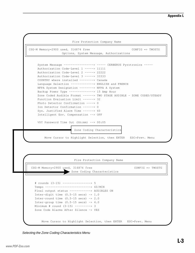
��*
��������
Fire Protection Company Name
CSG-M Memory=2900 used, 316874 free CONFIG => TWOSTG
Options, System Message, Authorizations
System Message -----------------> ----- CERBERUS Pyrotronics -----
Authorization Code-Level 1 -----> 11111
Authorization Code-Level 2 -----> 22222
Authorization Code-Level 3 -----> 33333
COUNTRY where installed --------> Canada
Language Selection -------------> ENGLISH and FRENCH
NFPA System Designation --------> NFPA A System
Backup Power Type --------------> 15 Amp Hour
Zone Coded Audible Format ------> TWO STAGE AUDIBLE - ZONE CODED/STEADY
Function Evaluation Limit ------> 32
Photo Detector Confirmation ----> 0
Ion Detector Confirmation ------> 0
Sys. Justified Alarm Time ------> 60
Intelligent Env. Compensation --> OFF
VDT Password Time Out (hh:mm) --> 00:05
Zone Coding Characteristics
Move Cursor to Highlight Selection, then ENTER ESC=Prev. Menu
Fire Protection Company Name
CSG-M Memory=2900 used, 316874 free CONFIG => TWOSTG
Zone Coding Characteristics
# rounds (3-15) ----------------> 5
Tempo --------------------------> 60/MIN
Final output status ------------> AUDIBLES ON
Inter-digit time (0.5-15 secs) -> 1.0
Inter-round time (0.5-15 secs) -> 2.0
Inter-group time (0.5-15 secs) -> 4.0
Minimum # round (3-15) ---------> 3
Zone Code Alarms After Silence -> YES
Move Cursor to Highlight Selection, then ENTER ESC=Prev. Menu
Selecting the Zone Coding Characteristics Menu
www.PDF-Zoo.com
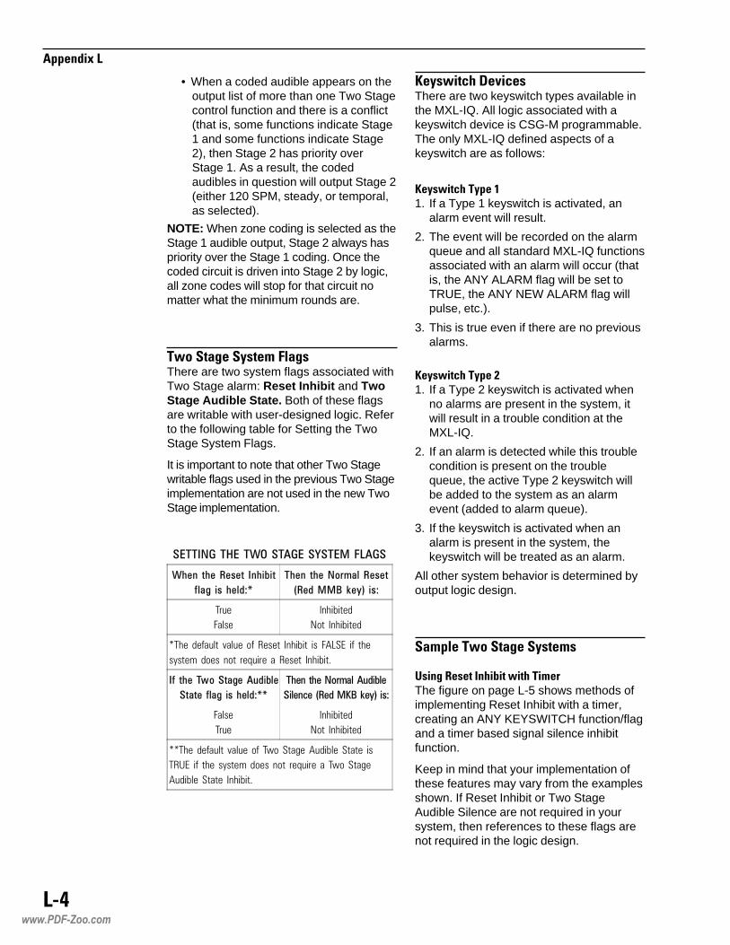
��+
��������
• When a coded audible appears on theoutput list of more than one Two Stagecontrol function and there is a conflict(that is, some functions indicate Stage1 and some functions indicate Stage2), then Stage 2 has priority overStage 1. As a result, the codedaudibles in question will output Stage 2(either 120 SPM, steady, or temporal,as selected).
NOTE: When zone coding is selected as theStage 1 audible output, Stage 2 always haspriority over the Stage 1 coding. Once thecoded circuit is driven into Stage 2 by logic,all zone codes will stop for that circuit nomatter what the minimum rounds are.
#� �!�� ��!����,���� �There are two system flags associated withTwo Stage alarm: Reset Inhibit and TwoStage Audible State. Both of these flagsare writable with user-designed logic. Referto the following table for Setting the TwoStage System Flags.
It is important to note that other Two Stagewritable flags used in the previous Two Stageimplementation are not used in the new TwoStage implementation.
���������������������� ���!� ����
�"��� �"�������� ��"����
#���� ��� "���$%
�"��� �"���&'��������
(����!!)�*�+,� ��$
���
�����
��������
��� ��������
���� ������� ������ ��� ����� ������� ��� ������ ��� ��
������ ����� ��� �� ����� �� ����� ������!
�#� �"���-���������������
������ #���� ���"���$%%
�"����"���&'����������
�����.��(����!/)�*�+,���$
�����
���
��������
��� ��������
����� ������� ������ ��� "�� �� ���������� ���� ��
�#�� ��� ��� ������ ����� ��� �� ����� �� "�� �� �
�������� ���� ������!
-�����"��&��"��There are two keyswitch types available inthe MXL-IQ. All logic associated with akeyswitch device is CSG-M programmable.The only MXL-IQ defined aspects of akeyswitch are as follows:
-�����"��#�����1. If a Type 1 keyswitch is activated, an
alarm event will result.
2. The event will be recorded on the alarmqueue and all standard MXL-IQ functionsassociated with an alarm will occur (thatis, the ANY ALARM flag will be set toTRUE, the ANY NEW ALARM flag willpulse, etc.).
3. This is true even if there are no previousalarms.
-�����"��#����$1. If a Type 2 keyswitch is activated when
no alarms are present in the system, itwill result in a trouble condition at theMXL-IQ.
2. If an alarm is detected while this troublecondition is present on the troublequeue, the active Type 2 keyswitch willbe added to the system as an alarmevent (added to alarm queue).
3. If the keyswitch is activated when analarm is present in the system, thekeyswitch will be treated as an alarm.
All other system behavior is determined byoutput logic design.
!�,����#� �!�� ��!����,�
.�� �/��������0������#,��The figure on page L-5 shows methods ofimplementing Reset Inhibit with a timer,creating an ANY KEYSWITCH function/flagand a timer based signal silence inhibitfunction.
Keep in mind that your implementation ofthese features may vary from the examplesshown. If Reset Inhibit or Two StageAudible Silence are not required in yoursystem, then references to these flags arenot required in the logic design.
www.PDF-Zoo.com

��1
��������
2��"�#� �!�� ��!����,The figure on page L-6 demonstrates abasic Two Stage system design. Itsoperation is summarized below:
• This system will output Stage 1audibles when the first alarm occurs.
• If the alarm is not acknowledged priorto the expiration of stg1_timer, codedaudibles will be forced output Stage 2audibles.
• If the alarm is acknowledged duringStage 1, only a keyswitch will placethe system in the second stage.
• If the system is reset after the alarmhas been acknowledged and codedaudibles silenced, the system may be
reset (provided the RESET INHIBITlogic permits).
• If a keyswitch is activated after theANY_ALARM flag is TRUE, thesystem will output the second stageaudibles.
• In either stage, the audible silenceflag/key controls the silencing andunsilencing of the coded audibles.
• The Panel Reset flag is used to assuretimers and latches are reset for thenext event after reset.
Trigger (ALL) Trigger (ALL)
Run Run
Enable Enable
Cancel Cancel
Start Timer Start Timer
True
Any Alarm
Reset Inhibit
RESET_INH
30 Sec
SS_INH
Two StageAudible Silence
Panel Reset
True
Any Alarm
False
OR(ANY)
List ofKeyswitch
Inputs
Keyswch AND(ALL)
Any_keyswchAny alarm
Typical RESET INHIBIT Timer Function Typical Signal Silence Inhibit Function
Typical ANY KEYSWITCH Function
Using Reset Inhibit with Timer
www.PDF-Zoo.com
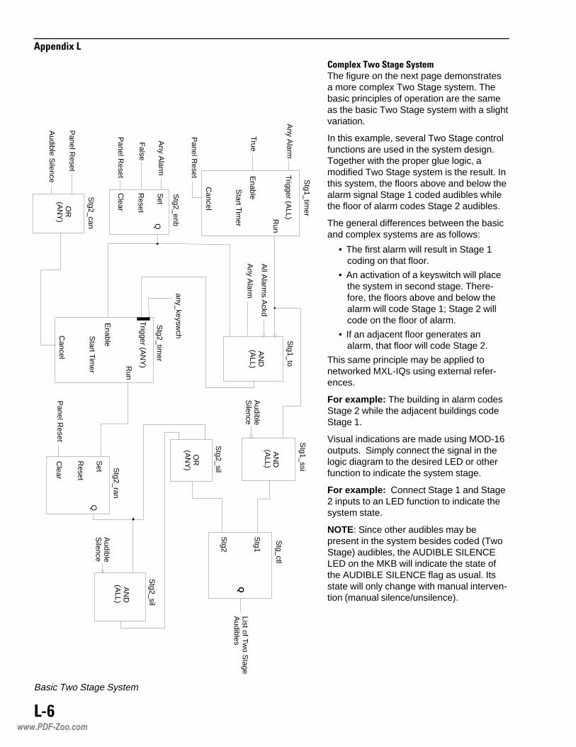
��3
��������
� ,����#� �!�� ��!����,The figure on the next page demonstratesa more complex Two Stage system. Thebasic principles of operation are the sameas the basic Two Stage system with a slightvariation.
In this example, several Two Stage controlfunctions are used in the system design.Together with the proper glue logic, amodified Two Stage system is the result. Inthis system, the floors above and below thealarm signal Stage 1 coded audibles whilethe floor of alarm codes Stage 2 audibles.
The general differences between the basicand complex systems are as follows:
• The first alarm will result in Stage 1coding on that floor.
• An activation of a keyswitch will placethe system in second stage. There-fore, the floors above and below thealarm will code Stage 1; Stage 2 willcode on the floor of alarm.
• If an adjacent floor generates analarm, that floor will code Stage 2.
This same principle may be applied tonetworked MXL-IQs using external refer-ences.
For example: The building in alarm codesStage 2 while the adjacent buildings codeStage 1.
Visual indications are made using MOD-16outputs. Simply connect the signal in thelogic diagram to the desired LED or otherfunction to indicate the system stage.
For example: Connect Stage 1 and Stage2 inputs to an LED function to indicate thesystem state.
NOTE: Since other audibles may bepresent in the system besides coded (TwoStage) audibles, the AUDIBLE SILENCELED on the MKB will indicate the state ofthe AUDIBLE SILENCE flag as usual. Itsstate will only change with manual interven-tion (manual silence/unsilence).
xxxx
Trigger (ALL)
Trigger (AN
Y)
Run
Run
Enable
Enable
Cancel
Cancel
Start Tim
er
Start Tim
er
Stg1_tim
er
Any A
larm
True
Panel R
eset
Set
Reset
Clear
QA
ny Alarm
False
Panel R
eset
Stg2_enb
AN
D(A
LL)
All A
larms A
ckd
Any A
larm
Stg1_to
Stg2_tim
er
any_keyswch
OR
(AN
Y)
Stg2_can
Panel R
eset
Audible S
ilence
Stg_ctl
Stg1_ssi
Stg1
Stg2
QList of Tw
o Stage
Audibles
AN
D(A
LL)A
udibleS
ilence
Set
Reset
Clear
Q
AN
D(A
LL)
OR
(AN
Y)
Stg2_sil
Stg2_ran
Stg2_sil
Panel R
eset
Audible
Silence
Basic Two Stage System
www.PDF-Zoo.com

��4
��������
Trigger (ALL)
Trigger (ANY)
Run
Run
Enable
Enable
Cancel
Cancel
Start Timer
Start Timer
Stg1_timer
Any Alarm
True
Panel Reset
Set
Reset
Clear
QAny Alarm
False
Panel Reset
Stg2_enb
AND(ALL)
All Alarms Ackd
Any Alarm
Stg1_to
Stg2_timer
any_keyswch
OR(ANY)
Stg2_can
Panel Reset
Audible Silence
Stg1_ssz3
Stg1_ssz1
Stg1_ssz2
Stg1
Stg1
Stg1
Stg2
Stg2
Stg2
Q
Q
Q
AND(ALL)
AND(ALL)
AND(ALL)
AudibleSilence
AudibleSilence
AudibleSilence
Set
Reset
Clear
Q
AND(ALL)
OR(ANY)
Stg2_sil
Stg2_ran
Stg2_sils
Panel Reset
AudibleSilence
flr1_2stg
flr2_2stg
flr3_2stg
First FloorTwo StageAudible List
Second FloorTwo StageAudible List
Third FloorTwo StageAudible List
Floor 3alarm pts
Floor 1alarm pts
Floor 1alarm pts
Floor 2alarm pts
Floor 3alarm pts
Floor 2alarm pts
stg1_flr1
stg1_flr2
stg1_flr3
stg2_flr1
stg2_flr2
stg2_flr3
OR(ANY)
OR(ANY)
OR(ANY)
AND(ALL)
AND(ALL)
AND(ALL)
To input list ofstg1_ssz1,stg1_ssz2,stg1_ssz3
stg1_timer
stg1_timer
stg1_timer
Stg2_sils
Stg2_sils
Stg2_silsUse toindicateStage Twois active
Com
plex Tw
o Stage S
ystem
www.PDF-Zoo.com

��5
��������
www.PDF-Zoo.com

���
��������
��������������� ��� ���� �
����� ���������������������
�������� ����������
The pre-alarm feature provides an earlywarning of smoke conditions at a moresensitive reading than alarm level. Thisindication can be in the following form:
• a displayed and printed pre-alarmreport
• output logic control
• both
Dual criteria logic allows for the distinctionbetween the chamber or thermal detectorof the ILPT-1 photo thermal.
The pre-alarm and dual criteria logicfunction (ILPT-1 only) features of the ILI orILP series of detectors are enabled by theFPI-32 Field Programmer.
Note: FPI-32 Rev. 1.3 or higher isrequired.
The FPI-32 also gives these detectors newunique IDs so that they can be identified atthe MXL-IQ as different from the ID-60I andID-60P series. The ID-60I and ID60Pdetectors still exist in the CSG-M, but thefeatures described in this appendix do notapply to them.
� ���� �������ILI ion detectors and ILP photoelectricdetectors are available as I/O device typesfor ALD-2s (or ALD-2Is). These device typestell the CSG-M and the MXL-IQ that theyhave the features of pre-alarm, dual criteria(photo thermal only), and ability to displayreadings in percent per foot (%/ft) obscuration.
These detectors appear in the CSG-M withthe existing ID-60I and ID-60P detectors.The MXL-IQ’s Custom Software Generator(CSG-M) allows the installation of the ILI orILP detectors at any valid ALD address.
���������Pre-alarm must be selected to eitherannunciate a detector’s pre-alarm or usethe detector in a Criteria Selection function.Pre-alarm can be enabled at each devicewhen it is installed as a Yes/No (Y/N) option.
The CSG-M provides the following systemoptions for pre-alarm:
• annunciate (Y/N)
• automatic adjust (Y/N)
• annunciation type – trouble
• learning period (1 - 30 days)
• activate detector LED (Y/N)
www.PDF-Zoo.com

���
��������
�������������������������The CSG-M provides a logic function typelabeled Criteria Selection. The followinginputs to this function are a detector’s:
• pre-alarm (from IL devices orAnalaser),
• verification, or
• chamber or thermal for the photothermal detector (ILPT-1)
Pre-alarm and chamber or thermal selec-tions cannot be mixed in the same function.The output can be any that is capable ofbeing driven by output logic, includingsending the output to another function.
Note: For networked MXL-IQ systems, noexternal panel inputs are allowed inthe Criteria Selection function.
� ��!"���������� ����������������������������� �����The MXL-IQ automatic pre-alarm learningfeature adjusts smoke detector pre-alarmlevels (during the time period selected inthe CSG-M) until they stabilize. Dependingupon pre-alarm activity, the system startswith the most sensitive pre-alarm level andgradually adjusts (de-sensitizes) theMXL-IQ until pre-alarms no longer occur.The level reached by each smoke detectorat the end of the learning period is thelearned pre-alarm level. No pre-alarmsannunciate or feed output logic during thislearning period.
The learned pre-alarm level is stored inflash memory so that on a panel power-on,watchdog, or nickel reset, the pre-alarmreadings still exist. When a new or modi-fied CSG-M is loaded into flash memory,the MXL-IQ will NOT assume pre-alarmexisted before and will re-start thelearning mode.
The flash memory used for storing pre-alarm detector readings shares the intelli-gent environmental control (IEC) flashmemory area. This requires that a bootblock flash device be used if pre-alarm isenabled. The flash segment size shared by
IEC and pre-alarm is 8K. Each IEC deviceuses 2 bytes and each pre-alarm deviceuses 1 byte, allowing a maximum of slightlyover 2500 devices with both IEC and pre-alarm.
Manual pre-alarm settings can be set at theMXL-IQ by using the CONTROL PER-CENT/FT PRE_ALARM command (SeePre-alarm and Sensitivity Settings below).Any valid pre-alarm reading within therange specified in the table on page M-3can be used. Pre-alarm adjustments are in%/ft obscuration. Manual settings overridethe learning mode settings. However, theydo not take effect until the end of thelearning period.
����������#$��������������Annunciation is a global yes/no option andthe type of annunciation is a trouble. Thetrouble report contains the type field text ofPre-alarm and both the INs and OUTs arerecorded. The format of these troublereports is identical to the format of allexisting MXL-IQ trouble or supervisoryreports.
Annunciation of a pre-alarm smoke detec-tor is provided even if the device goesimmediately into alarm. The alarm isreported first because of its higher priority,but a pre-alarm or trouble is also generatedthereafter with the same time and date.
Output logic control using the criteriafunction with ILI/ILP pre-alarm as thecriteria selection follows the INs and OUTs.If latching is desired, it must be added inthe CSG-M. Using the criteria selectionfunction to select either the chamber or thethermal for the ILPT-1 takes the MXL-IQ anadditional 5 seconds (or more) to evaluateafter the device alarms. This occursbecause a special status poll must be doneto determine whether it was the chamber orthe thermal that caused the alarm. Acriteria function with a selection of alarmverification provides an output for theduration a smoke detector is being verifiedor until reset if the device alarms.
�������������� ����$�%� ������Pre-alarm and sensitivity adjustments are in%/ft obscuration and have the followingranges, increments, and default values:
www.PDF-Zoo.com

��&
��������
PHOTO ION
Pre-alarm adjustincrement
.25% / ft. .12% / ft.
Pre-alarm range .25 - 2.0% / ft. .25 - .75% / ft.
Pre-alarmdefault
1.5% / ft. .75% / ft.
Sensitivity adjustincrement
~.25% / ft. ~.12% / ft.
Sensitivity range 1.25 - 3.4% / ft. .6 - 1.6% / ft.
Sensitivitydefault (Norm)
3.0% / ft. 1.4% / ft.
Because the pre-alarm and sensitivitysettings overlap, set the pre-alarm to atleast an increment below the sensitivitysetting.
����������������'��The FPI-32 (Rev. 1.3 or higher) must beused to enable the programming of the ILIand ILP IDs. The IDs tell the smokedetector it has the advanced features suchas pre-alarm. For more information aboutusing the FPI-32 with IL series detectors,refer to the FPI-32 Programmer/TesterOperations Manual, P/N 315-090077.
www.PDF-Zoo.com

��(
��������
www.PDF-Zoo.com

���
��������
����������� ��������
selbaC rebmuNtraP
4-BKMot2-/1-BMS 832291-555
)rewoPV42(4-/2-MOMot2-/1-BMS 505092-006
)ataDdnaV5(4-/2-MOMot2-/1-BMS 605091-555
yrettaBot2-/1-BMS 869091-555
elbaCgnimmargorPM-GSCot2-/1-BMS 407091-006
sesuF
wolBlamroNADMpmA02 710292-501
wolBlamroNGA3pmA51 090422-501
wolBlamroNGA3pmA8 858712-501
wolBlamroNGA3pmA2 857012-501
www.PDF-Zoo.com

���
��������
www.PDF-Zoo.com

���
��������
�������������� ��������������������������
�� ������ ���������������������������This powerful feature allows the user toreset the MXL-IQ by changing the state ofthe MID-16 or CZM-4 input. In CSG-MRevision 10.01, select the new Local ResetCausing usage for MID-16 or CZM-4 in theAvailable Device Usage Types screen:
������������
The system designer can connect theMID-16 or CZM-4 inputs to another systemvia a relay or have a remote reset input.When this input changes state to the off-normal position, the MXL-IQ resets in thesame way as a RED KEY reset. Existingevents do not need to be acknowledgedand audibles do not need to be silenced.
NOTE:This option is limited to NFPA 72A systems.In networked systems, the scope of thereset is local.
������ ��������When this option is set in the CSG-M forthe ALD loops, the ALD polls only up to thelast device installed on the loop, thusspeeding up the system response. Forexample, if there are only 5 devices in-stalled on the ALD loop, the MXL-IQ pollsonly up to address 5 on that loop instead ofpolling all 60 addresses.
The ALD Fast Polling option requiresALD-2I board Revision 14 and SMB ROMRev. 6.0. See the CSG-M Appendix for
Revision 10.01, P/N 315-096220, for settingthis option.
NOTE:The ALD Fast Polling option can only beused with Non-Fireprint Detectors.
��!����"���#����� �����$��%�����"%��If this feature is set in CSG-M, the MXL-IQautomatically sounds the trouble buzzerevery 24 hours from the time that thetrouble was acknowledged until the trouble iscleared. The troubles themselves are notre-annunciated.
"���#�������&�"%��������%�����������' ���"��This delay time was fixed at 30 seconds inthe previous MXL-IQ Revisions. In Revision6.0, the MXL-IQ delays the TRI dampertravel delay time trouble according to thetime that is selected in CSG-M. The delaytime is programmable from 0 to 90 secondsin 1 second increments.
����&��������������������The delay time is programmable in CSG-Mfrom 0 to 90 seconds in 1 second increments.The default value for this option is 0 seconds,which results in an immediate reporting ofthe trouble.
If an AC failure occurs, the MXL-IQ checksthe database for the delay time and starts
www.PDF-Zoo.com
��
��������
the timer if the delay time is other than zero.No AC failure trouble is reported at this time.
At the end of this delay time, if the AC stillfails, the MXL-IQ posts the AC Failuretrouble; otherwise, it goes back to theoriginal state.
��'��������������(�A new selection is added to the list ofprinter selections under the Global MKB inthe Network map of the CSG-M: CCU/MPager Interface. The new selectionprovides a remote interface between theMXL-IQ panel and the operator.
This selection is available in all situationswhere a printer was previously available.For a 72 Proprietary networked system(72D system), this selection is availableunder a Display Only Global MKB. Thereare only two selections in this configuration:NONE and CCU/M.
When programmed into the CSG-M, thispager interface can be either supervised orunsupervised. The CCU/M interface is anapplication specific output device, and not aglobal MKB printer for a 72D system. There-fore, if it is installed on a 72D networkedsystem, it does not satisfy the compilecheck for a supervised printer. To pass thiscompile error, add a supervised printer to alocal MKB in every node in a 72D system.
Despite the above limitation, in both 72Aand 72D systems the CCU/M interfacecounts as one GMKB printer available in anetworked system.
Only the normal print messages for eventsare sent to the CCU/M interface. Informa-tion such as acknowledge, reset, timechanges, etc., do not output. The outputformatting is considered as a generic ASCIIprinter.
www.PDF-Zoo.com

�����
�������������� � ������� �����������
���������������
��������������������
�����������������������������������
�� ������!������ ������������ ����������"�#����$�$��
�� ��%
������������������������&����
�����!������������#
���������������������
�� ����������������
���������!��������
�������������� �����������������������
�!!����������!������������������%��������%����
�' � �����!!����������!���������������
�(�����)����� ����������*����
+,�"��(��������
�����!�����������&
+-.�(��������
�����!�����������&
�*�������������������������������������&
**/�!�������������� ������������ ����������"�#���$�$��
*�%��##
������������������������&����
�����!�����������0
���������������������
���!���(�����������������
*1��2
������������������������&���3
�����!�����������0
��������������������2
�� ����������������
*'��2
���������������������
45,�������45,�����������45,���##����&���0
45,��&����������&���&
45,��&��� ����!���-�����&���6
45,��&��1������'���������&���6
�����!�����������6
��������������������2
�� ����������������
*7���+"
������������������������&�����
���������!����&����2
�������������������&�����
!�������&����3
�����!������������2
*7��2
������������������������&����&
�����!�����������0
��������������������2
�� ����������������
����)�����*����� �����!���� ������������ ����������"�#
���$�$��
����������������������+����
�����������!���(��� �������!���(���������
%�'�����������������
�����!������������3
-���
�����!������������3
���������������������������������
������www.PDF-Zoo.com

�����
�����
��������������5��������5����
�5,�'�����������������
�����!�������������
�8�����)���
��!��)���"���"����"����#
� �(�������������������"���6
� �(��� �����������������"���6
� �������������)�������������"���0
(�����������������������"���&
����� ��������$������������"���0
��������"���"
����������"���"
��� �������������)�������������"���0
����������������"���6
!���������������"���6
��������������"���"
�����������������"���&
�����������������"�����
��9 �������"����2
���������9 ��)���"���3
��������$�����"��������"���2
�!��������"����
���(�������(��������������"���2
�����������"����
!���������������"����#����"�����
�%*,�:�%*,�+"
�����!�������������
% �'�����������������
�����!�����������������������
%�*� ��������������
%�%�'�����������������
�����!�������������
%�,�'�����������������
�����!�������������
%�-
�����!�������������
�����$��:��������$������ (������;����
�%���
�����!������������2
���� � �����<+�2���!�������
�����������������6
�������������6���������0
'�� ���)�������������������
' !�������)��������0���������#
-�� (����������#����������
*��������������"��������2�
���������������2#
���:����������6
*$�����!!��������2�
���!������������0
���!� �������������0��������2#
4��������1�9 ����������2#
= �! ����:�����������6���������0
,������:���������2���������2�
1������������&
'���������)��������&
����������������������"
�����������������������2
��������������������������2
�' >�!!���������3���������"
������-)!���������0
������/�����������������������
www.PDF-Zoo.com

������
�������������������0���������#
�� ����������6���������0
4�����������������
= �! ��'��������������
,������:����������2���������3
'�� ���)��������3���������"
'���������)��������"
'��������?��������������#����������
'��� ����������
' !�������)��������2
-��!��������6
-�� (����������2���������3
?��������������"���������6
-����������2���������20
�' > �������������26
��>�������������2&
�������� �������23
���������������2&
;�� ��5� ���������22
���!�-����������23
��� �����������������20
�=%����!�-����������2"
=�������������2"��������2&
,�����������22��������23
,���������������2&��������26
,)�������������2&
'���-����������2���������22
' �����@�������26��������20
-����4�������A.�4������4��B�������2"
��� �����������������3
�% ��"
������������������������&�����
�����!�������������
�������������������0
�<+�2
�����!�����������3
��(����!�������������������������2
��!��)����������������
��)!�������������������2
������������������������������������
�������������������2
�������!���������������
������������"��������6
���������)!��������3
��!��)��������
��!��)���)��������3
���������� �(���������2
�� ��������3
���������!��������������3
� ��������)!��������2
��� ���)��������#����������
�!������A����C�� ������B���)!��������3
� !�����������������6��������0
��� (����������0���������#
�����$����� ������2
��������� ����D����������!������������ ������
�� ����������������
�= ��"
������������������������&�����
�����!������������#
�������������������0
�!���������������
�� ����������� �����������
�=%�&
������������������������&����0
�����!������������#
�������������������0
�� ����������������
�!���������������
�=���
������������������������&����3
�����!�����������6
�������������������"��������0
www.PDF-Zoo.com
������
������=��2
������������������������&����&
�����!�����������6
�������������������"��������0
�,'�":�"D���,'���:���D
�����!�����������3
����������������������������2
�'����
��������������������
�'%�'������������ �����������
�����!������������2
�.��,�����' !!�)�����*��� ���������� ����
�.��%E
(��������!�������������2
(�����)����� ����������*����
�����!������������
����� ������� ��������������
�������� ����������"�#����$�$����=����
!������ !!�)��������� ���������� ����
����������������
��������� ����������"�#����$�$����=��������=����
�2�$� ����� (������� ��:����������������=����
�� ������!��������=����
**/�!����������������=����
���)�����*����� �����!������=��������=����
�������� ����@������=����
��� (������)������������!����������� ����-1%���=����
4%���1
�����������������������&����0����&�����
���������������������&�����
��������)���������������A5'%B���&�����
����������&����0
����������������������A4**B���&����#
�����!�������������
��������������������2
�,����
�����!�����������"
�������������������"
,+����0�
�����!������������3
,��'�����������������
�����!������������3
!�������!���������(�� �����������������������
,%���
�����!�����������"
�������������������3
,%���:,����
�������������������"
!��������������������<����
!������ !!�)��������� ���������� ����
!�������������������������
��������� ����@���������% ��"����*7��2� �������
���� ����������"�#����$�$������������ ����@���
������!���� ���
$�����������������
�����������������������������
���� ���)�!������������������8����
����������������� (���� ��������$��:��������$����� (���
'������<��$�������3��6:3��0
������������������������&�����
'�+��
������������������������&����3
�������������&����"����&����6
�����������������&����3
�����!�����������2
��������������������
�� ���������������
www.PDF-Zoo.com

������
������!����!������������4����
������ !�!���� ����������#���������"
�)������!�����������(��������������������2
�)������������4 - 1
��������!���� ������2����
-1%�'��������������������� ���
�����!������������2
��� (������)������������!����������� ����-1%� ����������� ����������"�#����$�$��
��� (�������������F��������F���6
��� (������� ��:��������������� ������������ ���������"�#����$�$��
-�� (���$������; �����2����
-'D��
�����!�������1 - 6
��������������������
����������������*����������������������&
�D���������3��������3���"
�!������������ ���������3���2
�����������3����
� �����!���� �����3��������3����
www.PDF-Zoo.com

������
�����
www.PDF-Zoo.com

�������������C��3���+�����"%+����������%����%��"%��%+��"%����5"��
C����(����"�(�%����5���+����+%�����%�����������%���"�%���
#�+��+������+"��+������%��%����%(��%������+�"5�"�����+��"%���
��������%+�������+��%��=����+��+���%���5�����+�����3�(
#�+��+�������+��5�"�%�/�%���;����3�+������6����3�"��%�+�+�
�%"+�����5�!//�$������#�����%"�����������+��3"�6����"�%����
%=���3"�+��+����%�%���+��������+�"5�"�����#�����3�"%+������%
�����"��%����6�"�����+��.3�"%+�����5�+�����C��3���+����%
"������+�%��%"�%������&��(�+���%������+�"5�"��������#������%��
+������"�%+������#���>3�����#����=��"�C��"���+��+%&��#�%+�
�6�"���%��"����%(�=��"�C��"���+����""��+�+�����+�"5�"�����
www.PDF-Zoo.com

����������� ���
������������������������������� ��!"�#�$�%����&�'�#��$�'���'$(����%�)�$��*�+��
�������������������������������,-�!��.'�-���'$����-$��-&��������/�����0�-'$����, ����+���
www.PDF-Zoo.com

NOTES:1. For Installation Instructions for the MXL-IQ modules refer
to the Table below.2. Waterflow Alarm must be AccuLINK (CSG-M) configured
to at least one non-silenceable NAC.3. Refer to the MXL-IQ OPERATION, INSTALLATION,
AND MAINTENANCE MANUAL (P/N 315-093624) forminimum NFPA configurations and additional information.
4. Use the following batteries: BTX-1, BTX-2, or BP-61.5. The CSM-4 module is capable of the following functions:
Leased Line CircuitSupervised Local Energy Auxiliary Trip (Municipal Tie)Supervised Notification Appliance CircuitReleasing Service
6. CRM-4 relay coils are supervised when not energized;contacts are not.
7. For alternate configurations using CZM-1/1B6s, consultTechnical Support.
8. Optional transient suppressors Model CP2341 andCP2297 may be used in addition to the transientprotection incorporated in the panel and not in lieu ofthat protection. Use them for extreme lightningconditions. For CP2297 refer to instructions P/N 315-092355.For CP2341 refer to instructions P/N 315- 092390.
9. For the Silent Knight 5128/5129 Central Station, RemoteStation connection (NFPA 72), refer to instructions P/N315-093294.
10. The modules indicated with an asterisk in the Table beloware rated power limited on all terminals. Refer to theMXL-IQ Power Limited Wiring Instructions, P/N 315-095445,for separation of power limited wiring.
11. When the CSM-4 is configured for Municipal Tie orReleasing Service, terminals 1 and 4 and/or terminals 9and 12 are non-power limited. In all other applications, theCSM-4 is power limited on all terminals.
12. For a list of Compatible Notification Appliances, referto P/N 315-096363.
!"#$%&'()*+,&
-,./0))0/'-"'-,./1*2/'-"
!"#$%&'()*+,&
-,./0))0/'-"'-,./1*2/'-"
!"#$%&'!(()$"*+
,-##.+/0)#.+
0$*1+0$*2+ †!/$*3+
!45/$*3+!0$*3+
!.+"!45$.+"
!/$*"&4/$%"*0$56*
4/$%7*
8$040/-($8/)8$-8#/-($8/)#$88)#-($8/)#$()-#-($8/)
+)89(-($8/)-$089(-($8/)9$8#,(-($8/)#$88)8-($8/),$4#,(-($8/)4$0,0#-($8/)#$4()8-($8/)8$8)/#-($8/)#$(49/-($8/))$8,8)-($8/)0$()9(-($8/)
!,$"7*#$*7*0$*7*4$2.*#/$2.*
1/$*":/$&'.!/$*".
#$*".'8$2.
!,:8$2.;/</$++1
#$5*2#$=2>
#$--,#-($8/)8$,,,#-($8/),$#89(-($8/))$0))(-($8/))$()(#-($8/)0$)8-#-($8/)8$9(0#-($8/)(/$#40/-($8/)
8$9(0#-($8/)0$,4)#-($8/)4$-#,#-($8/)#$04)8-($8/)#$/)-8-($8/)#$))0#-($8/)
'3-./04)01.2/1()56/.*12.12(72,87,,)2(78(-,92(7(20'3-./02)):;
<2,'.=2(7*> ?20): (1-0+(7?"(-.$
@#A&>7,,$3,)0-: ?@A'A44B+%C() ?@A'A44B+%C() DEFGHIFJEFHKF2%"LMHN?@AEALO((/
DEFGHIFJEFHKF2.;<&"LMHN?@AEALO(8
7,,$B:C@#A&> 1=;JFKFMPHQRSC0# † ?@A'A#/B 1=;JFKFMPHQRSC0# † ?@A'8T/B ?@AEALO)
@#A&>2(D,EFAGHG#&IB
1=;JFKFMPHQRSC0# †B?@A'/
1=;JFKFMPHQRSC0# †B?@A'/ U?@AE45/</$*3+(/V!?@AEALO0
"@#J$: ?@A'A(4B+%C() ?@A'A(4B+%C() DEFGHIFJEFHKF2%"LMHN?@AEALO((/DEFGHIFJEFHKF2.;<&"LMHN?@AEALO(8
K#&IB +%C8T0#$(#?@A'A0
?@A+%C8T0#?@A'A(9/ ?@AEALO(,
FAGHG#&IB +%C8T0#$9/?@A'A0
?@A+%C8T0#?@A'A80 ?@AEALO8)
7,,$B:CK#&>B 1=;JFKFMPHQRSC0# † ?@A'A#/B 1=;JFKFMPHQRSC0# † ?@A'A8T/B ?@AEALO)
K#&>B(.L)07.1.-*&
1=;JFKFMPHQRSC0# †B?@A'A#/
1=;JFKFMPHQRSC0# †BUWK@MRFAOAV'A(#)$(## UJ@OPXRHJSPGRHV?@AEALO8T##
K#&>B(-.$+('0($
1=;JFKFMPHQRSC0# †B?@A'A-$)
1=;JFKFMPHQRSC0# †B?@A'A-$)
EALO68T#UJ@OPJR@FRHPEFJSPGRHV
K#&>B(1.=2(>3-.'0()(4
+%C0#?@A'A#/
+%C0#?@A'A((9 ?@AEALO)
7etoNeeS* † JFHQHMGF1FI@=PPS;Y1=;
������������ ����������������
������� � �� ������� ����������� ��
������� ����� ���� ���
��������� ����� ���� ���
��������� ��������������������
�������������� ���
��� ����������������
����������������
������� ������������������
��� ������������������� ���
����� ����������������
����
�� �������� ��������������
�������� !"#!�$���%!��&�"&��'( �)�)�*+"�*#!""�$$�%���#��!�#!�$���%#!������"&�!�!�
������',-
�� ������������������������������������� !
��������� ������
� �� ��������� �� ������� ��
�',- . ��������
���',- . �������
(��/ ��0���1����������������
�����������0������������������
��������������������������������
2%3(��/ � ��0����� ��������
(���/ ��0���1����������������
�����������0������������������
��������������������������������
���������������� ���0���1����� ��� ������
����������� �������0����
�������������������
����������� ���0���1����� �� �����
���� ���0���1����� ��������
2%3���� �����������0����
�������������������
����� ���0���1����� ��������
((����� ���0���1����� �� ������
2%3((����� � �����������0����
�������������������
���� ���0���1����� ���������
��������' . ����������
����������' . ����������
/�����' . ��������
��'���' . ��������
�������������� . ��������
'������ . ��������
��������� . ������������������� ����������������������������� !
��������"������#! #!����4��5���0')�*+�67*���8!$�6�!"*������)�(
��#�+8#* #����#9� �!*��$*6����-:��)�1%�#&9* �!$"*'�;�-�)���)<
�$&%#*����*%�"&"*�$*4�%�)���)+%��$�6�"�7�"&8��!*��$*6����$&%�!�"��*#!9�*"&!)
����������� ��
"����� ����������������
������� � �� ������� ����������� ��
(������� ����� ���� ���
(��������� ����� ���� ���
(��������� ��������������������
�������������� ���
(��� ����������������
����������������
((����� ����� ���������
(������� ������������������
��� ������������������� ���
(����� ����������������
�������
�� �������� ��������������
�������� !"#!�$���%��!��&�"&��'(�7��$1"�$*4�%6��!*�*%%�!�%��1�������!�6�=((
���!>9�*��*�*�*��',-�!�%��$���!$
�������������� ��™ Model MXL-IQ CONNECTION DIAGRAM
For Proprietary Burglary Application (1076) use aTSW-2 tamper switch to monitor the main enclosure.Monitor each TRI-60/60R/60D or TRI-B6/B6R/B6Drelated to this application (1076) for 24 hours by alisted motion detector to prevent tampering.
����������������������������������
��!�"�#����$�%�
!��"�%���%"&����#�'�"��(�)��
�������������������������������*+�
�)�,%�+���%"����+"��+
$��������-�����.�+%"���*/��0��� �
†See Note 11
www.PDF-Zoo.com