manual sirius 3sk1 safety relays - siemens ag€¦ · · 2015-09-30manual industrial controls...
TRANSCRIPT

Manual
Industrial ControlsSafety EngineeringSIRIUS 3SK1 Safety Relays
Edition 09/2015
siemens.com

SIRIUS 3SK1 safety relays
___________________
___________________
___________________
___________________
___________________
___________________
___________________
___________________
___________________
___________________
___________________
___________________
___________________
___________________
___________________
___________________
Industrial Controls
Safety engineering SIRIUS 3SK1 safety relays
Manual
09/2015 A5E02526190021A/RS-AC/003
Introduction 1
Product-specific safety information
2
Product overview for 3SK1 3
Safety systems - General information
4
3SK1 devices 5
System configuration 6
Circuit diagrams 7
Mounting 8
Connection 9
Configuration / operation 10
Commissioning 11
Display and diagnostics 12
Technical data 13
Dimension drawings 14
Accessories 15
Appendix A

Siemens AG Division Digital Factory Postfach 48 48 90026 NÜRNBERG GERMANY
3ZX1012-0SK11-0AC0 Ⓟ 09/2015 Subject to change
Copyright © Siemens AG 2013. All rights reserved
Legal information Warning notice system
This manual contains notices you have to observe in order to ensure your personal safety, as well as to prevent damage to property. The notices referring to your personal safety are highlighted in the manual by a safety alert symbol, notices referring only to property damage have no safety alert symbol. These notices shown below are graded according to the degree of danger.
DANGER indicates that death or severe personal injury will result if proper precautions are not taken.
WARNING indicates that death or severe personal injury may result if proper precautions are not taken.
CAUTION indicates that minor personal injury can result if proper precautions are not taken.
NOTICE indicates that property damage can result if proper precautions are not taken.
If more than one degree of danger is present, the warning notice representing the highest degree of danger will be used. A notice warning of injury to persons with a safety alert symbol may also include a warning relating to property damage.
Qualified Personnel The product/system described in this documentation may be operated only by personnel qualified for the specific task in accordance with the relevant documentation, in particular its warning notices and safety instructions. Qualified personnel are those who, based on their training and experience, are capable of identifying risks and avoiding potential hazards when working with these products/systems.
Proper use of Siemens products Note the following:
WARNING Siemens products may only be used for the applications described in the catalog and in the relevant technical documentation. If products and components from other manufacturers are used, these must be recommended or approved by Siemens. Proper transport, storage, installation, assembly, commissioning, operation and maintenance are required to ensure that the products operate safely and without any problems. The permissible ambient conditions must be complied with. The information in the relevant documentation must be observed.
Trademarks All names identified by ® are registered trademarks of Siemens AG. The remaining trademarks in this publication may be trademarks whose use by third parties for their own purposes could violate the rights of the owner.
Disclaimer of Liability We have reviewed the contents of this publication to ensure consistency with the hardware and software described. Since variance cannot be precluded entirely, we cannot guarantee full consistency. However, the information in this publication is reviewed regularly and any necessary corrections are included in subsequent editions.

SIRIUS 3SK1 safety relays Manual, 09/2015, A5E02526190021A/RS-AC/003 5
Table of contents
1 Introduction ........................................................................................................................................... 11
1.1 User responsibility for system design and function ................................................................ 11
1.2 Required basic knowledge ...................................................................................................... 11
1.3 Validity range .......................................................................................................................... 11
1.4 Definitions ............................................................................................................................... 11
1.5 Service&Support ..................................................................................................................... 12
1.6 Configurator for 3SK1 safety relays ........................................................................................ 14
1.7 DataMatrix code ...................................................................................................................... 15
1.8 Correction sheet ...................................................................................................................... 16
1.9 History ..................................................................................................................................... 16
2 Product-specific safety information ........................................................................................................ 17
2.1 General safety notes ............................................................................................................... 17
2.2 Intended use ........................................................................................................................... 19
2.3 Current information about operational safety ......................................................................... 20
2.4 Declaration of conformity ........................................................................................................ 20
3 Product overview for 3SK1 .................................................................................................................... 21
3.1 Overview ................................................................................................................................. 21
3.2 Overview of components and accessory parts ....................................................................... 24
3.3 Functional scope of the 3SK1 basic units ............................................................................... 25
3.4 Introduction ............................................................................................................................. 26
3.5 3SK1 system ........................................................................................................................... 27 3.5.1 Standard ................................................................................................................................. 27 3.5.1.1 Typical system configuration .................................................................................................. 27 3.5.2 Advanced ................................................................................................................................ 28 3.5.2.1 Typical system configuration .................................................................................................. 28
4 Safety systems - General information .................................................................................................... 31
4.1 What is safety? ....................................................................................................................... 31
4.2 Safety function ........................................................................................................................ 32
4.3 Basic terminology .................................................................................................................... 33 4.3.1 Redundancy/single-channel and two-channel ........................................................................ 33 4.3.2 Cross-circuit detection ............................................................................................................ 34 4.3.3 Enabling circuit (safety-related output) ................................................................................... 34 4.3.4 Semiconductor signaling circuit .............................................................................................. 35 4.3.5 Feedback circuit ...................................................................................................................... 35

Table of contents
SIRIUS 3SK1 safety relays 6 Manual, 09/2015, A5E02526190021A/RS-AC/003
4.3.6 Stop categories ...................................................................................................................... 35 4.3.7 Automatic start ....................................................................................................................... 36 4.3.8 Manual start ........................................................................................................................... 36 4.3.9 Monitored start ....................................................................................................................... 37 4.3.10 Two-hand operation/synchronism .......................................................................................... 38 4.3.11 Cascading .............................................................................................................................. 39 4.3.12 Startup testing ........................................................................................................................ 39 4.3.13 Connection of actuators ......................................................................................................... 40 4.3.14 Series connection of sensors ................................................................................................. 43
5 3SK1 devices ........................................................................................................................................ 45
5.1 3SK1 standard ....................................................................................................................... 45 5.1.1 General information ............................................................................................................... 45 5.1.2 Applications ............................................................................................................................ 45 5.1.3 3SK1111 Standard basic unit instantaneous (with relay outputs) ......................................... 46 5.1.3.1 General information ............................................................................................................... 46 5.1.3.2 Function description ............................................................................................................... 46 5.1.3.3 Design .................................................................................................................................... 47 5.1.3.4 Terminal assignment .............................................................................................................. 48 5.1.3.5 Inputs ..................................................................................................................................... 48 5.1.3.6 Outputs ................................................................................................................................... 49 5.1.3.7 Display of the operating state ................................................................................................ 49 5.1.3.8 Function setting ...................................................................................................................... 49 5.1.4 3SK1112 Standard basic unit instantaneous (with semiconductor outputs) ......................... 52 5.1.4.1 General information ............................................................................................................... 52 5.1.4.2 Function description ............................................................................................................... 53 5.1.4.3 Design .................................................................................................................................... 54 5.1.4.4 Terminal assignment .............................................................................................................. 55 5.1.4.5 Inputs ..................................................................................................................................... 55 5.1.4.6 Outputs ................................................................................................................................... 56 5.1.4.7 Display of the operating state ................................................................................................ 56 5.1.4.8 Function setting ...................................................................................................................... 57
5.2 3SK1 Advanced ..................................................................................................................... 59 5.2.1 General information ............................................................................................................... 59 5.2.2 Applications ............................................................................................................................ 59 5.2.3 General device features ......................................................................................................... 60 5.2.4 Function description ............................................................................................................... 60 5.2.5 Functions ................................................................................................................................ 61 5.2.6 3SK1121 Advanced basic unit instantaneous (with relay outputs) ........................................ 63 5.2.6.1 Device features ...................................................................................................................... 63 5.2.6.2 Function description ............................................................................................................... 63 5.2.6.3 Design .................................................................................................................................... 64 5.2.6.4 Terminal assignment .............................................................................................................. 65 5.2.7 3SK1121 Advanced basic unit time-delayed (with relay outputs) .......................................... 66 5.2.7.1 Device features ...................................................................................................................... 66 5.2.7.2 Design .................................................................................................................................... 67 5.2.7.3 Terminal assignment .............................................................................................................. 68 5.2.8 3SK1122 Advanced basic unit instantaneous (with semiconductor outputs) ........................ 70 5.2.8.1 Device features ...................................................................................................................... 70 5.2.8.2 Design .................................................................................................................................... 71 5.2.8.3 Terminal assignment .............................................................................................................. 72 5.2.9 3SK1122 Advanced basic unit time-delayed (with semiconductor outputs) .......................... 74

Table of contents
SIRIUS 3SK1 safety relays Manual, 09/2015, A5E02526190021A/RS-AC/003 7
5.2.9.1 Device features ....................................................................................................................... 74 5.2.9.2 Design ..................................................................................................................................... 75 5.2.9.3 Terminal assignment ............................................................................................................... 76 5.2.10 3SK1120 Advanced basic unit instantaneous (with semiconductor outputs) ......................... 78 5.2.10.1 Device features ....................................................................................................................... 78 5.2.10.2 Design ..................................................................................................................................... 79 5.2.10.3 Terminal assignment ............................................................................................................... 80 5.2.10.4 Status diagrams ...................................................................................................................... 81
5.3 3SK1 output expansions ......................................................................................................... 82 5.3.1 Applications ............................................................................................................................. 82 5.3.2 Function description ................................................................................................................ 83 5.3.3 Display of the operating state ................................................................................................. 83 5.3.4 Function setting ....................................................................................................................... 83 5.3.5 Output expansion 3SK1211 .................................................................................................... 84 5.3.5.1 Device features ....................................................................................................................... 84 5.3.5.2 Design of 3SK1211-.B..0 ........................................................................................................ 85 5.3.5.3 Design of 3SK1211-.BB40 ...................................................................................................... 86 5.3.5.4 Terminal assignment ............................................................................................................... 87 5.3.6 Output expansion 3SK1213 .................................................................................................... 88 5.3.6.1 Device features ....................................................................................................................... 88 5.3.6.2 Design of 3SK1213-.AB40 ...................................................................................................... 89 5.3.6.3 Design of 3SK1213-.A.20 ....................................................................................................... 90 5.3.6.4 Terminal assignment ............................................................................................................... 90 5.3.7 3RM1 Failsafe motor starters ................................................................................................. 91
5.4 3SK1 input expansions ........................................................................................................... 92 5.4.1 Input expansion 3SK1220 ....................................................................................................... 92 5.4.1.1 Device features ....................................................................................................................... 92 5.4.1.2 Applications ............................................................................................................................. 92 5.4.1.3 Design ..................................................................................................................................... 93 5.4.1.4 Terminal assignment ............................................................................................................... 94 5.4.1.5 Display of the operating state ................................................................................................. 94 5.4.1.6 Function setting ....................................................................................................................... 94 5.4.2 Power supply 3SK1230........................................................................................................... 96 5.4.2.1 Device features ....................................................................................................................... 96 5.4.2.2 Applications ............................................................................................................................. 96 5.4.2.3 Design ..................................................................................................................................... 97 5.4.2.4 Terminal assignment ............................................................................................................... 98 5.4.2.5 Display of the operating state ................................................................................................. 98
6 System configuration ............................................................................................................................. 99
6.1 General information ................................................................................................................ 99 6.1.1 General notes on the Standard system .................................................................................. 99 6.1.2 General information on the Advanced system ........................................................................ 99 6.1.3 Maximum system configuration ............................................................................................ 100
6.2 3ZY12 device connector ....................................................................................................... 104 6.2.1 Device features ..................................................................................................................... 104 6.2.2 Applications ........................................................................................................................... 106
6.3 System configuration rules ................................................................................................... 107

Table of contents
SIRIUS 3SK1 safety relays 8 Manual, 09/2015, A5E02526190021A/RS-AC/003
7 Circuit diagrams ................................................................................................................................... 111
7.1 Internal circuit diagrams ....................................................................................................... 111 7.1.1 Internal circuit diagrams for 3SK1 Standard basic units ...................................................... 111 7.1.2 Internal circuit diagrams for 3SK1 Advanced basic units .................................................... 113 7.1.3 Internal circuit diagrams for expansion units ....................................................................... 116
7.2 Typical circuits ...................................................................................................................... 120 7.2.1 Typical circuits ...................................................................................................................... 120
7.3 Typical circuits of 3SK1 safety relays with 3RM1 Failsafe motor starters ........................... 129 7.3.1 3SK1 safety relay with 3RM1 Failsafe motor starter via device connector ......................... 129 7.3.2 3SK1 safety relay wired with 3RM1 Failsafe motor starter .................................................. 131
7.4 Additional applications ......................................................................................................... 133
8 Mounting .............................................................................................................................................. 135
8.1 Warning notices ................................................................................................................... 135
8.2 Terminal coding.................................................................................................................... 136
8.3 Mounting the devices on a level surface .............................................................................. 137
8.4 Disassembling devices from a level surface ........................................................................ 139
8.5 Mounting 22.5 mm/17.5 mm devices on a standard mounting rail ...................................... 141
8.6 Mounting the 90 mm devices on a standard mounting rail .................................................. 142
8.7 Removing devices from a standard mounting rail ................................................................ 143
8.8 Mounting 22.5 mm/17.5 mm devices with device connectors on a standard mounting rail ........................................................................................................................................ 144
8.9 Removing 22.5 mm/17.5 mm devices with device connectors from a standard mounting rail ......................................................................................................................... 147
8.10 Mounting 90 mm devices with device connectors on a standard mounting rail .................. 150
8.11 Removing 90 mm devices with device connectors from a standard mounting rail .............. 153
8.12 Mounting 22.5 mm/17.5 mm devices with device connectors on the wall ........................... 156
8.13 Removing 22.5 mm/17.5 mm devices with device connectors from the wall ...................... 159
8.14 Mounting 90 mm devices with device connectors on the wall ............................................. 161
8.15 Removing 90 mm devices with device connectors from wall .............................................. 164
8.16 Mounting the sealable cover ................................................................................................ 166
9 Connection .......................................................................................................................................... 167
9.1 22.5 mm/17.5 mm devices ................................................................................................... 167 9.1.1 Terminal assignment ............................................................................................................ 167 9.1.2 Connection data for terminals .............................................................................................. 168 9.1.3 Connecting the screw-type terminals ................................................................................... 169 9.1.4 Disconnecting the screw-type terminals .............................................................................. 170 9.1.5 Wiring rules for spring-loaded terminals (with push-in technology) ..................................... 171 9.1.6 Connecting the push-in terminals ........................................................................................ 172 9.1.7 Disconnecting the push-in terminals .................................................................................... 174 9.1.8 Attaching the terminals ........................................................................................................ 175 9.1.9 Disconnecting ....................................................................................................................... 176

Table of contents
SIRIUS 3SK1 safety relays Manual, 09/2015, A5E02526190021A/RS-AC/003 9
9.2 Devices 90 mm ..................................................................................................................... 178 9.2.1 Opening the terminal cover ................................................................................................... 178 9.2.2 Connection data for terminals ............................................................................................... 179 9.2.3 Connecting terminals ............................................................................................................ 180 9.2.4 Mounting terminals ................................................................................................................ 182 9.2.5 Disconnecting ....................................................................................................................... 183
9.3 Device replacement .............................................................................................................. 185
10 Configuration / operation ..................................................................................................................... 187
10.1 Procedure for configuration .................................................................................................. 187
10.2 Explanation of the device's functions .................................................................................... 188
10.3 Modes ................................................................................................................................... 191
10.4 Response times .................................................................................................................... 192
11 Commissioning ................................................................................................................................... 195
12 Display and diagnostics....................................................................................................................... 197
12.1 LED display ........................................................................................................................... 197
12.2 Power-up ............................................................................................................................... 199
12.3 Error statuses ........................................................................................................................ 199
12.4 Diagnostics ........................................................................................................................... 200
13 Technical data .................................................................................................................................... 203
13.1 Data sheet ............................................................................................................................. 203
13.2 General technical data .......................................................................................................... 204
14 Dimension drawings ............................................................................................................................ 209
14.1 Dimension drawings for 3SK1 devices ................................................................................. 209
14.2 Dimension drawings for 3SK1 device connector .................................................................. 217
15 Accessories ........................................................................................................................................ 223
A Appendix............................................................................................................................................. 225
A.1 Correction sheet .................................................................................................................... 225

Table of contents
SIRIUS 3SK1 safety relays 10 Manual, 09/2015, A5E02526190021A/RS-AC/003

SIRIUS 3SK1 safety relays Manual, 09/2015, A5E02526190021A/RS-AC/003 11
Introduction 1 1.1 User responsibility for system design and function
The products described here were developed to perform safety-related functions as part of an overall installation or machine.
A complete, safety-related system is generally equipped with sensors, evaluation units, and signaling units, and uses reliable shutdown concepts.
It is the responsibility of the manufacturer of a system or machine to ensure that the product functions properly. Siemens AG, its regional offices, and associated companies (hereinafter referred to as "Siemens") cannot guarantee all the properties of an entire plant, system or machine that has not been designed by Siemens.
Nor can Siemens assume liability for recommendations that appear or are implied in the following description. No new guarantee, warranty, or liability claims beyond the scope of the Siemens general terms of supply are to be derived or inferred from the following description.
1.2 Required basic knowledge A general knowledge of the following areas is needed in order to understand this manual:
● Low-voltage switchgear
● Digital circuit logic
● Automation systems
● Safety systems
1.3 Validity range The manual is valid for these safety relays SIRIUS 3SK1. It describes the components that are valid at the time of publication.
SIEMENS reserves the right of including a Product Information for each new component, and for each component of a later version.
1.4 Definitions "3SK1" always applies to all variants of the SIRIUS 3SK1 safety relays.

Introduction 1.5 Service&Support
SIRIUS 3SK1 safety relays 12 Manual, 09/2015, A5E02526190021A/RS-AC/003
1.5 Service&Support
Online Support The Online Support in the Service&Support portal is an extensive information system for all questions relating to Siemens products and solutions. This service enables direct and central access to in-depth information concerning the products, systems and applications for industry and to a large number of programming, configuration and application examples. Its content is available via a mobile app.
The Technical Forum of the Online Support provides the opportunity for users to swap information. Support Request allows contact to be established with Siemens experts in Technical Support.
Siemens Industry Online Support ensures that users in industry are always kept up-to-date with news, software updates and announcements by means of newsletters and Twitter.
Links: Service&Support Portal (http://support.automation.siemens.com), Online Support (http://support.automation.siemens.com/WW/view/en/16605022)
Product Support Are you looking for product information such as technical data, updates or FAQs? Here, the "Product Support" section of the Service & Support Portal offers an extensive collection of all information about the Siemens Industry Automation and Drive Technologies products and solutions:
● Answers to frequently asked questions (FAQs)
● Updates/upgrades, service packs and support tools for downloading
● Manuals and operating instructions
● Technical data/CAx data
● Approvals and certificates
● Test certificates and characteristic curves
All Product Support information is at your disposal free of charge and around the clock, and you always get the current version.
Link: Product Support (http://support.automation.siemens.com/WW/view/en/4000024)

Introduction 1.5 Service&Support
SIRIUS 3SK1 safety relays Manual, 09/2015, A5E02526190021A/RS-AC/003 13
CAx data The CAx Download Manager provides you with a simple means of gaining access to up-to-date product data for your CAx or CAe system.
You configure your own download package with just a few clicks. You can choose from the following information for products
● Product images
● 2D dimensional drawings
● 3D models
● Internal circuit diagrams
● EPLAN macro files
● Manuals
● Characteristics
● Operating instructions
● Certificates
● Product master data
Link: CAx Download Manager (http://support.automation.siemens.com/WW/view/en/42455541)
Applications & Tools Applications & Tools supports you with various tools and examples when it comes to solving your automation tasks. Solutions are presented in interaction with several components in the system, without focusing on individual products.
● Application examples
● Function blocks & tools
● Background and system descriptions
● Performance statements
● Demonstration systems/videos
Link: Applications & Tools (http://support.automation.siemens.com/WW/view/en/20208582)

Introduction 1.6 Configurator for 3SK1 safety relays
SIRIUS 3SK1 safety relays 14 Manual, 09/2015, A5E02526190021A/RS-AC/003
My Documentation Manager My Documentation Manager enables you to compile your own documentation from our standard documents (manuals), which are located in the Product Support section. Under mySupport, you have the opportunity to create and manage you own compilations in a structure of their own.
Link:
MyDocumentationManager (http://support.automation.siemens.com/WW/view/en/38715968)
Reference You can find further information on structure and navigation in Online Support here (http://support.automation.siemens.com/WW/view/en/4000024).
1.6 Configurator for 3SK1 safety relays
Configurator Various configurators are available on the Internet to assist you with configuration.
The configurator for 3SK1 safety relays and matching accessories is an easy-to-use selection and configuration tool. You can select the individual components and plan your system in accordance with your specific requirements. You can save your selection, export it as a text file or you can order it directly.
The configurator automatically compiles a document list of the information available in Service&Support for every component. You can use it as the basis for putting together your system documentation.
Link:
● Configurator (http://www.siemens.com/industrial-controls/configurators)

Introduction 1.7 DataMatrix code
SIRIUS 3SK1 safety relays Manual, 09/2015, A5E02526190021A/RS-AC/003 15
1.7 DataMatrix code A DataMatrix code is lasered onto the lower terminal cover of all 3SK1-series safety relays.
DataMatrix codes are standardized in ISO/IEC 16022. The DataMatrix codes on Siemens devices use ECC200 coding for powerful error correction.
The following device information is encoded in the DataMatrix codes as a bit stream:
● Article number (MLFB)
● Serial number
● MAC address, if applicable
This information is stored in the following format in the DataMatrix code: 1P Article number
(MLFB) + S serial number
(+ 23S MAC address) Data identifier Net content Separator
Note
The information content is displayed without spaces.
This machine-readable information simplifies and accelerates handling of the respective devices. As well as fast access to the serial numbers of the respective devices for unique identification, the DataMatrix codes simplify communication with Siemens Technical Support.
SIEMENS Industry Support App The Data Matrix codes enable in particular extremely fast and convenient access to all the device-specific information available on an article number (MLFB) in the SIEMENS Service&Support Portal, such as operating instructions, manuals, data sheets, FAQs, etc. We offer the SIEMENS Industry Support App free for this purpose. This can be used on commercially available smartphones and tablet PCs. The SIEMENS Industry Support App is available for iOS and Android-based terminal devices and can be accessed via the following links:
Link for Android Link for iOS

Introduction 1.8 Correction sheet
SIRIUS 3SK1 safety relays 16 Manual, 09/2015, A5E02526190021A/RS-AC/003
1.8 Correction sheet The appendix to this manual contains a correction sheet for evaluation and feedback. Please use it to record your suggestions for improvements, additions and corrections, and return the sheet to us. This will help us to improve the next edition of the manual. Thank you.
1.9 History Product version New features 02/2013 Initial release 02/2014 Integration of 3RM1 Failsafe motor starters 09/2015 Revision of the manual

SIRIUS 3SK1 safety relays Manual, 09/2015, A5E02526190021A/RS-AC/003 17
Product-specific safety information 2 2.1 General safety notes
Note Recycling and disposal
Dispose of existing packing material in accordance with applicable regulations or recycle it.
3SK1 safety relays are able to be recycled thanks to a low-pollutant manufacturing process. For environmentally-friendly recycling and disposal of your electronic waste, please contact a company certified for the disposal of electronic waste.
Note SILCL 3 to IEC 62061:2005/PL e/Cat. 4 to EN ISO 138491:2008
3SK1 safety relays are designed in such a way as to allow implementation of applications up to SILCL 3 in accordance with IEC 62061 and PL e/Kat. 4 in accordance with EN ISO 13849-1.
Note Safe state
The basis of the safety function is the definition of the safe state. In the case of safety relays, this is the "OFF state", i.e. an open contact for sensors or shutdown of the actuators.
WARNING
Protection against electrically conductive contamination!
The devices must be protected against conductive contamination while taking account of the ambient conditions. One way you can do this is to install the devices in a control cabinet with the appropriate degree of protection.
You will find more detailed information in IEC 60529, for example.
WARNING
Safe functional extra-low voltage
The 3SK1 safety relays with a supply voltage of 24 V DC must be operated with safe functional extra-low voltage (SELV, PELV). This means these modules must only be subjected to a voltage of Um even in the event of a fault. The following applies for these 3SK1 safety relays: Um < 60.0 V. You can find more detailed information about safe functional extra-low voltage in the data sheets of the power supplies to be used.

Product-specific safety information 2.1 General safety notes
SIRIUS 3SK1 safety relays 18 Manual, 09/2015, A5E02526190021A/RS-AC/003
CAUTION
Protection against electrostatic charge
When handling and installing 3SK1 safety relays, ensure that the components are protected from being electrostatically charged. Changes to the system configuration and wiring are only permissible while the supply voltage is switched off. Connection of 3SK1 safety relays is only permissible when the power supply units (PELV and SELV) are switched off.
CAUTION
Noise immunity / grounding
The following must be grounded in accordance with the regulations to ensure noise immunity of the 3SK1 safety relays: • PELV / SELV power supply units (please also note the documentation for the respective
power supply unit in this regard).
Note
Cover the 3ZY12 device connector on the left-hand side using the cover supplied with the device termination connector.
WARNING
3SK1..1 and 3SK1..3 safety relays (devices with outputs using contacts): In continuous operation, the key safety values apply where the function test interval (state change of the outputs) for SIL2 ≤ 1 year and for SIL3 ≤ 1 month.
3SK1..2 and 3SK1120 safety relays (devices with semiconductor outputs up to product version E01/V1.0.0): In continuous operation, the key safety values apply where the function test interval (state change of the outputs) ≤ 1 year.
3SK1..2 and 3SK1120 safety relays (devices with semiconductor outputs from product version E02/V1.1.0): In continuous operation, the key safety values apply where the function test interval (state change of the outputs) ≤ 20 years.
Function test procedure: • Actuate the connected sensors. • Check their effect on the safety relay and the downstream actuators. • Activate the safety relay via the connected sensors. • Check their effect on the safety relay and the downstream actuators. • Defective devices must be replaced.

Product-specific safety information 2.2 Intended use
SIRIUS 3SK1 safety relays Manual, 09/2015, A5E02526190021A/RS-AC/003 19
Note
3SK1..2 and 3SK1120 safety relays (devices with semiconductor outputs) as from E02/V1.1.0 run power-on tests, so-called light tests, at regular intervals in the "OFF state".
WARNING
As a result of light tests at the semiconductor outputs, the level changes to the ON state for up to 2.5 ms. Users are responsible for ensuring that this does not result in any actuator changing to the active state.
Note 3ZY12 device connectors
Only safety relays with a supply voltage of 24 V DC may be used on the 3ZY12 device connector.
2.2 Intended use
WARNING
Hazardous Voltage. Can Cause Death, Serious Injury, or Property Damage. Proper use of hardware products
This equipment is only allowed to be used for the applications described in the catalog and in the technical description, and only in conjunction with non-Siemens equipment and components recommended by Siemens.
Correct transport, storage, installation and assembly, as well as careful operation and maintenance, are required to ensure that the product operates safely and without faults.
EU note: Commissioning is absolutely prohibited until it has been ensured that the machine in which the component described here is to be installed complies with the stipulations of the Directive 2006/42/EC.

Product-specific safety information 2.3 Current information about operational safety
SIRIUS 3SK1 safety relays 20 Manual, 09/2015, A5E02526190021A/RS-AC/003
2.3 Current information about operational safety
Important note for maintaining operational safety of your system
WARNING
Hazardous Voltage Can Cause Death, Serious Injury, or Property Damage. Please take note of our latest information.
Systems with safety-related characteristics are subject to special operational safety requirements on the part of the operator. The supplier is also obliged to comply with special product monitoring measures. For this reason, we publish a special newsletter containing information on product developments and features that are (or could be) relevant to operation of safety-related systems. By subscribing to the appropriate newsletter, you will ensure that you are always up-to-date and able to make changes to your system, when necessary:
SIEMENS newsletter (http://www.industry.siemens.com/newsletter)
Register under "Products and Solutions” for the following newsletter: • Industrial Controls - SIRIUS News (en) • Safety Integrated Newsletter
2.4 Declaration of conformity The manufacturer declares that the safety components of the SIRIUS 3SK1 series in the designs marketed by us comply with the applicable basic safety and health requirements of the EC Directives* stated (including amendments) and that the stated standards* were applied in their design and construction.
* You can download the complete EC Declaration of Conformity as a PDF.

SIRIUS 3SK1 safety relays Manual, 09/2015, A5E02526190021A/RS-AC/003 21
Product overview for 3SK1 3 3.1 Overview
Overview of 3SK1 safety relays The following tables provide an overview of the 3SK1 safety relays.
3SK1 basic units Standard Designation Voltages Article number (MLFB) 3SK1 basic unit Standard instantaneous (with relay outputs) 24 V AC/DC 3SK1111-xAB30
110 ... 240 V AC/DC 3SK1111-xAW20 3SK1 basic unit Standard instantaneous (with semiconductor outputs) 24 V DC 3SK1112-xBB40 x = 1: screw terminals; x = 2: push-in terminals
3SK1 Advanced basic units Designation Voltages Article number (MLFB) 3SK1 Advanced basic unit instantaneous (with relay outputs) 24 V DC 3SK1121-xAB40 3SK1 Advanced basic unit time-delayed (with relay outputs) 24 V DC 3SK1121-xCB4y 3SK1 Advanced basic unit instantaneous (with semiconductor outputs) 24 V DC 3SK1122-xAB40 3SK1 Advanced basic unit time-delayed (with semiconductor outputs) 24 V DC 3SK1122-xCB4y 3SK1 Advanced basic unit 17.5 mm instantaneous (with semiconductor output)
24 V DC 3SK1120-xAB40
x = 1: screw terminals; x = 2: push-in terminals y = 1: 0.05 ... 3 s; y = 2: 0.5 ... 30 s; y = 4: 5 ... 300 s

Product overview for 3SK1 3.1 Overview
SIRIUS 3SK1 safety relays 22 Manual, 09/2015, A5E02526190021A/RS-AC/003
Expansion units Designation Voltages Article number (MLFB) 3SK1211 output expansion 24 V AC 3SK1211-xBB00
24 V DC 3SK1211-xBB40 110 ... 240 V AC/DC 3SK1211-xBW20
3SK1213 output expansion 24 V DC 3SK1213-xAB40 115 V AC 3SK1213-xAJ20 240 V AC 3SK1213-xAL20
3SK1220 input expansion 24 V DC 3SK1220-xAB40 3SK1230 power supply 110 ... 240 V AC/DC 3SK1230-xAW20 3RM1 Failsafe direct-on-line starters 24 V DC 3RM11..-xAA4 3RM1 Failsafe reversing starters 24 V DC 3RM13..-xAA4 x = 1: screw terminals; x = 2: push-in terminals
x = 3 (3RM1 only) hybrid connection method: Control circuit realized as push-in spring-loaded terminal and main circuit as screw terminal
Overview of the safety-related outputs Type and number of safety-related outputs Advanced
Relay Semiconductors Semiconductor signaling circuits
Device connectors Instantaneous Delayed Instantaneous Delayed
3SK1121-xAB40 3 - - - 1 ✓ 3SK1121-xCB4x 2 2 - - - ✓ 3SK1122-xAB40 - - 3 - 1 ✓ 3SK1122-xCB4x - - 2 2 - ✓ 3SK1120-xAB40 - - 1 - - ✓ Standard 3SK1111-xAxx0 3 - - - 1 - 3SK1112-xBB40 - - 2 - 1 - Output expansions 4RO 3SK1211 4 - - 1 ✓ (for 24 V DC) 3RO 3SK1213 3 - - - 1 ✓ (for 24 V DC)

Product overview for 3SK1 3.1 Overview
SIRIUS 3SK1 safety relays Manual, 09/2015, A5E02526190021A/RS-AC/003 23
Online configurator To assist you with configuration, the "SIRIUS 3SK1 safety relay configurator" is at your disposal on the Internet (http://www.siemens.com/industrial-controls/configurators). You can select and order the correct safety relays here and generate the complete product documentation:
● Product data sheet
● Dimension drawings
● CAD data in 2-D and 3-D model images
● Ordering data
● Product photo

Product overview for 3SK1 3.2 Overview of components and accessory parts
SIRIUS 3SK1 safety relays 24 Manual, 09/2015, A5E02526190021A/RS-AC/003
3.2 Overview of components and accessory parts
① 3SK1 safety relay (basic unit/expansion unit) ② Top cover flap ③ Bottom cover flap ④ Terminals, 3-pole, push-in, 1 x 2.5 mm² ⑤ Terminals, 3-pole, screw-type, 1 x 2.5 mm² ⑥ Terminals, 2-pole, push-in, 1 x 2.5 mm² ⑦ Terminals, 2-pole, screw-type, 1 x 2.5 mm² ⑧ Coding pins ⑨ Push-in lugs for wall mounting ⑩ Cover ⑪ Device connector for 3SK1 safety relay, 17.5 mm wide ⑫ Device connector for 3SK1 safety relay, 22.5 mm wide ⑬ Device termination connector for 3SK1 safety relay, 22.5 mm wide ⑭ Sealable cover

Product overview for 3SK1 3.3 Functional scope of the 3SK1 basic units
SIRIUS 3SK1 safety relays Manual, 09/2015, A5E02526190021A/RS-AC/003 25
3.3 Functional scope of the 3SK1 basic units Function 3SK1 Standard 3SK1 Advanced Type of safety-related outputs Relays Semiconductors Relays Semiconductors Sensors Mechanical sensors ✓ ✓ ✓ ✓ Non-floating sensors ✓ ✓ ✓ ✓ Antivalent sensors Not possible Not possible ✓ ✓ Sensor number can be increased Not possible Cascading only ✓ ✓ Parameter Type of start (autostart/monitored start) ✓ ✓ ✓ ✓ Sensor connection 2x single-channel / 1x two-channel
Using wiring ✓ ✓ ✓
Cross-circuit detection OFF / ON Using wiring ✓ ✓ ✓ Start-up test OFF / ON No start-up test ✓ ✓ ✓ Monitoring of two-hand control units Not possible Not possible ✓ ✓ Safety-related outputs Instantaneous ✓ ✓ ✓ ✓ Delayed None None ✓ ✓ Expandable with relay outputs Using wiring Using wiring ✓ ✓ Device connector Cannot be used Cannot be used ✓ ✓ Rated control supply voltage 24 V DC ✓ ✓ ✓ ✓ 110 ... 240 V AC/DC ✓ Not possible ✓1) ✓1)
1) Possible using 3SK1230 power supply and device connector

Product overview for 3SK1 3.4 Introduction
SIRIUS 3SK1 safety relays 26 Manual, 09/2015, A5E02526190021A/RS-AC/003
3.4 Introduction SIRIUS 3SK1 safety relays are used mainly in autonomous safety applications that are not connected to a safety-related bus system. Here they are used to evaluate sensors and ensure safety-related shutdown when required. They also check and monitor the sensors, actuators, and the safety-related functions of the safety relay.
Applications Depending on the version of the device and the external connection of sensors and actuators, applications up to SILCL 3 in accordance with IEC 62061, SIL 3 in accordance with IEC 61508 and PL e (Cat. 4) in accordance with ISO 13849-1 can be implemented.
● Monitoring the switch position of the sensors
● Monitoring of the sensor lines
● Monitoring of correct functioning of the safety relay
● Monitoring of the actuators
● Safety-related shutdown in case of hazards

Product overview for 3SK1 3.5 3SK1 system
SIRIUS 3SK1 safety relays Manual, 09/2015, A5E02526190021A/RS-AC/003 27
3.5 3SK1 system
3.5.1 Standard
3.5.1.1 Typical system configuration
System configuration for 3SK1 Standard A 3SK1 Standard system can comprise the following devices:
● Basic units (one basic unit per system)
– 3SK1111 Standard basic unit instantaneous (with relay outputs) (Page 46)
– 3SK1112 Standard basic unit instantaneous (with semiconductor outputs) (Page 52)
● Output expansions
– Output expansion 3SK1211 (Page 84)
– Output expansion 3SK1213 (Page 88)
The devices are connected using wiring.
Typical 3SK1 Standard system configuration
① Basic unit 3SK1 Standard ② Output expansion 3SK1211 ③ Output expansion 3SK1213

Product overview for 3SK1 3.5 3SK1 system
SIRIUS 3SK1 safety relays 28 Manual, 09/2015, A5E02526190021A/RS-AC/003
3.5.2 Advanced
3.5.2.1 Typical system configuration
System configuration for 3SK1 Advanced A 3SK1 Advanced system can comprise the following devices:
● Basic units (one basic unit per system)
– 3SK1121 Advanced basic unit instantaneous (with relay outputs) (Page 63)
– 3SK1121 Advanced basic unit time-delayed (with relay outputs) (Page 66)
– 3SK1122 Advanced basic unit instantaneous (with semiconductor outputs) (Page 70)
– 3SK1122 Advanced basic unit time-delayed (with semiconductor outputs) (Page 74)
– 3SK1120 Advanced basic unit instantaneous (with semiconductor outputs) (Page 78)
● Input expansions
– Power supply 3SK1230 (Page 96)
– Input expansion 3SK1220 (Page 92)
● Output expansions
– Output expansion 3SK1211 (Page 84)
– Output expansion 3SK1213 (Page 88)
– 3RM1 Failsafe motor starter output expansion (you will find additional information in the manual SIRIUS 3RM1 motor starters (http://support.automation.siemens.com/WW/view/en/66295730))
● (Optional)3ZY12 device connector (Page 104)
The devices are connected by means of 3ZY12 device connectors or wiring.
When a 3ZY12 device connector is used, there is no wiring whatsoever between the basic unit and the expansion unit(s). In this case, all necessary signals are exchanged via the device connector.
You will find the rules for configurations with device connectors in the section "System configuration rules (Page 107)".

Product overview for 3SK1 3.5 3SK1 system
SIRIUS 3SK1 safety relays Manual, 09/2015, A5E02526190021A/RS-AC/003 29
Typical 3SK1 Advanced system configuration
① 3SK1230 power supply ② 3SK1220 input expansion ③ 3SK1 basic unit Advanced ④ 3SK1211 output expansion ⑤ 3SK1213 output expansion

Product overview for 3SK1 3.5 3SK1 system
SIRIUS 3SK1 safety relays 30 Manual, 09/2015, A5E02526190021A/RS-AC/003
Typical 3SK1 Advanced system configuration with 3RM1 Failsafe motor starter
① 3SK1220 input expansion ② 3SK1 basic unit Advanced ③ 3SK1211 output expansion ④ 3RM1 Failsafe motor starter output expansion
① 3SK1230 power supply ② 3SK1220 input expansion ③ 3SK1 basic unit Advanced ④ 3SK1211 output expansion ⑤ 3RM1 Failsafe motor starter output expansion ⑥ 3SK1213 output expansion

SIRIUS 3SK1 safety relays Manual, 09/2015, A5E02526190021A/RS-AC/003 31
Safety systems - General information 4 4.1 What is safety?
Safety defines a state in which the risk of damage is reduced to a tolerable level, or which can be regarded as risk-free. Following on from this definition, functional safety concerns persons, machines and the environment.
The objective of safety systems is to reduce the risk for humans and machines that is posed by a use case to an acceptable level. The first step is, therefore, to identify the risk of a use case. In order to make a reliable assessment regarding the application, each individual function of a machine or plant must be analyzed for potential hazards.
For further information, refer to the brochure "Safety of machines and plants" which is available here as a download: Functional safety (http://www.siemens.com/safety).

Safety systems - General information 4.2 Safety function
SIRIUS 3SK1 safety relays 32 Manual, 09/2015, A5E02526190021A/RS-AC/003
4.2 Safety function A safety function describes the reaction of a machine/plant to the occurrence of a specific event (e.g. opening of a protective door). Execution of the safety function(s) is carried out by a safety-related control system. This usually comprises three subsystems, detecting, evaluating and reacting.
Detecting (sensors):
● Detecting a safety requirement, e. g.: EMERGENCY STOP or a sensor for monitoring a hazardous area (light array, laser scanner, etc.) is operated.
Evaluating (safety relay):
● Detecting a safety requirement and safely initiating the reaction (e.g. switching off the safety-related outputs).
● Monitoring the correct operation of sensors and actuators
● Initiating a reaction upon detection of faults
For the 3SK1 products described in this manual, this concerns evaluation units for safety functions.
Reacting (actuators):
● Switching off the hazard by means of downstream actuators.

Safety systems - General information 4.3 Basic terminology
SIRIUS 3SK1 safety relays Manual, 09/2015, A5E02526190021A/RS-AC/003 33
4.3 Basic terminology
4.3.1 Redundancy/single-channel and two-channel
Redundancy With redundancy, more than one component is implemented for the same function, so a faulty function of a component is performed instead by the other component(s).
A redundant configuration reduces the probability of a function failing due to a single defective component. This requirement is essential for achieving SILCL 3 in accordance with IEC 62061, SIL 3 in accordance with IEC 61508 and PL e (Cat. 4) in accordance with ISO 13849-1 (also necessary for SIL 2 / PL d under certain circumstances).
The simplest form of redundancy is two-channel redundancy.
If a circuit fails, two-channel redundancy or appropriate wiring ensures that the safety function is maintained.
In a redundant system configuration, the subsystems for detecting and reacting must also be implemented with two-channel redundancy.
Note
All SIRIUS Safety devices that comply with SILCL 3 in accordance with IEC 62061, SIL 3 in accordance with IEC 61508 and PL e (Cat. 4) in accordance with DIN EN ISO 13849-1 are redundantly configured with regard to the internal logic as well as with regard to the output circuits.
Figure 4-1 Single-channel sensor connection

Safety systems - General information 4.3 Basic terminology
SIRIUS 3SK1 safety relays 34 Manual, 09/2015, A5E02526190021A/RS-AC/003
Figure 4-2 Two-channel sensor connection
* = positively-driven auxiliary contacts/mirror contacts
4.3.2 Cross-circuit detection Cross-circuit detection is a diagnostic function of a safety relay that detects short-circuits and cross-circuits between the input channels (sensor circuits) during two-channel sensing or reading. A cross-circuit can be caused, for example, by a cable casing being squashed. In devices without cross-circuit detection, this can mean that a two-channel EMERGENCY STOP circuit does not trip even though only one NC contact is faulty (secondary error).
With 3SK1 devices, a cross-circuit is detected in the sensor circuits by means of signals with different clock pulses. If the clocked signals overlap, the device detects a cross-circuit. With 3SK1 basic units, cross-circuit detection can be deactivated to allow electronic sensors to be evaluated (that monitor themselves as well as the cable to the evaluation unit.
4.3.3 Enabling circuit (safety-related output) An enabling circuit provides a safety-related output signal. From an external viewpoint, enabling circuits usually act as NO contacts (however, in terms of functionality, safety-oriented opening is always the most important aspect).
An individual enabling circuit that is redundantly configured internally in the safety relay can be used for SIL 3 / PL e.
Note: Enabling current paths can also be used for signaling purposes. 3SK1 safety relays are only equipped with enabling circuits with NO functionality. This means that when the safety function is triggered, or a fault is detected, the enabling circuits will always transfer to the safe state (NO contact open).

Safety systems - General information 4.3 Basic terminology
SIRIUS 3SK1 safety relays Manual, 09/2015, A5E02526190021A/RS-AC/003 35
4.3.4 Semiconductor signaling circuit A current signaling path provides a safety-related output signal. Signaling circuits can be implemented with either NC or NO contact functionality.
With 3SK1 relays, the semiconductor signaling circuits are always implemented as NC circuits. This means that when the safety function is triggered or a fault is detected, the semiconductor signaling circuits will always close.
4.3.5 Feedback circuit A feedback circuit is used to monitor controlled actuators (e.g. relays or load contactors) with positively-driven contacts or mirror contacts. The safety-related outputs can only be activated if the feedback circuit is closed.
Note
When 3SK1 expansion units are used on 3ZY12 device connectors with 3SK1 Advanced basic units, it is not necessary to incorporate the expansion modules in the feedback circuit wiring. This is implemented internally via the device connector.
4.3.6 Stop categories
Stop category 0 Non-controlled shutdown by immediately switching off the power to the machine's drive elements.
Stop category 1 Controlled stopping where the energy feed is interrupted with a time delay, or is only interrupted once standstill has been reached.
Note
Time-delayed shutdown of safety-related outputs in accordance with Stop category 1 is not ensured under all operating states.
In the case of some internal device faults, and when disconnecting the supply voltage, these safety-related outputs are switched off instantaneously.

Safety systems - General information 4.3 Basic terminology
SIRIUS 3SK1 safety relays 36 Manual, 09/2015, A5E02526190021A/RS-AC/003
4.3.7 Automatic start For an automatic start, the device is started without manual confirmation, but only after the input image has been checked and a positive test of the safety relay has been conducted. This function is also known as dynamic operation and is not permissible for EMERGENCY STOP devices. Safety devices for prohibited danger zones (e.g. position switches, light arrays, safety shutdown mats) can use the automatic start function if this does not pose any risk.
Note
An automatic start is not permitted for EMERGENCY STOP devices.
Information about start response in the system configuration 3SK1 Advanced units can be found in the chapter "Explanations of device function (Page 188)".
4.3.8 Manual start For a manual start, the device is started by operating the START button, but only after the input image has been checked and a positive test of the safety relay has been conducted. On a manual start, the START button is not monitored for correct operation, a positive edge of the START button is sufficient for starting.
Note
The "Manual start" function is only available with the 3SK1111 safety relays (slide switch at Autostart position).
Note
Manual start is not permitted for EMERGENCY STOP devices.
Figure 4-3 Start function "Manual start"

Safety systems - General information 4.3 Basic terminology
SIRIUS 3SK1 safety relays Manual, 09/2015, A5E02526190021A/RS-AC/003 37
4.3.9 Monitored start For a monitored start, the device is started by operating the START button, but only after the input image has been checked and a positive test of the safety relay has been conducted.
Contrary to the manual start, the monitored start evaluates a signal change of the START button. This means that the START button cannot be bypassed (misuse). For PL e (ISO 13849-1) as well as SIL 3 (IEC 62061), the monitored start must be used in the case of EMERGENCY STOP. For other safety sensors/functions, the necessity for a monitored start command depends on the risk assesment.
If the START button is operated for more than 2 seconds, the 3SK1 basic unit detects a wiring short-circuit in the START button and switches to the fault state (Device = green; SF = flashing red; Out = flashing yellow; IN = off)
Note
In the delivery state of the 3SK1 safety relays, the start type is set to "Monitored start".
Figure 4-4 Start function "Monitored start"
Safety systems - General information 4.3 Basic terminology
SIRIUS 3SK1 safety relays 38 Manual, 09/2015, A5E02526190021A/RS-AC/003
4.3.10 Two-hand operation/synchronism Synchronous sensor operation is a special form of simultaneity of sensors.
In this case, it is not sufficient for sensor contacts 1 and 2 to be switched to the closed state at different times, they must be closed within 0.5 seconds.
Synchronism of sensors is required, in particular, in the case of two-hand operation of presses. This ensures that the presses only become active when the sensors are operated simultaneously with both hands. This minimizes the risk of the operator getting a hand in the press.
When 3SK1 safety relays are used, you can achieve applications up to type IIIc in compliance with EN 574 (applications up to PL e/Cat. 4 in compliance with EN 13849-1 or SILCL 3 in compliance with IEC 62061).
Note
In the delivery state of 3SK1 safety relays, monitoring of time synchronism is deactivated. Time synchronism can be activated using the following adjustable parameter for 3SK112 Advanced and 3SK122 Advanced: • Jumper T1/PAR (NO/NC evaluation) • DIP switches (1) Autostart • DIP switches (3) 2 x single-channel
Note
The 3SK1 Advanced safety relays exclusively support two-hand control units with two NO contacts.
Note
The two-hand circuit must be marked in compliance with EN 574. You can find information on determining the response time in the section entitled Response times (Page 192).

Safety systems - General information 4.3 Basic terminology
SIRIUS 3SK1 safety relays Manual, 09/2015, A5E02526190021A/RS-AC/003 39
4.3.11 Cascading Cascading of safety relays is used for tripping safety relays in series.
Several safety functions can then be logically connected to a shared shutdown path. Several safety-related outputs can be created for selective shutdown of drive elements.
The connection between the individual modules must be arranged on one side only, because cascading from the last relay to the first one would create a loop which would prevent starting.
Cascading is implemented within a control cabinet in a single-channel configuration; this is even permissible with SIL 3 / PL e, because cable routing within a control cabinet is protected against short-circuits and short-circuiting to P potential (fault exclusion in accordance with ISO 13849-2).
The 3SK1 Advanced device series offers an extremely convenient solution for cascading. Input expansions can be easily connected to the evaluation unit by means of device connectors.
4.3.12 Startup testing The sensor or protection equipment must be opened and closed again after the supply voltage is restored before the enables for the 3SK1 safety relay can be switched through.
Startup testing ensures that any errors in the sensors are detected (again), because safety relays lose their ability to store errors at zero voltage.
Unauthorized manipulation of the protection equipment can also be detected through startup testing.
The plant operator decides whether startup testing should be performed (risk assessment). No general statements apply.
Note
In the delivery state of 3SK1 safety relays, startup testing is deactivated.

Safety systems - General information 4.3 Basic terminology
SIRIUS 3SK1 safety relays 40 Manual, 09/2015, A5E02526190021A/RS-AC/003
4.3.13 Connection of actuators
Note
To achieve the Performance Level / Safety Integrity Level given in the following examples, the actuators shown must be monitored in the feedback circuit of the corresponding safety relay.
Note
For capacitive and inductive loads, we recommend an adequate protective circuit. In this way, electromagnetic interference can be suppressed and contact service life increased.
You can find additional information in SIRIUS Innovations - SIRIUS 3RT2 Contactors/Contactor Assemblies manual (http://support.automation.siemens.com/WW/view/en/60306557).
Actuator wiring up to PL c / Cat. 2 in accordance with ISO 13849-1 or SILCL 1 in accordance with IEC 62061
Figure 4-5 PL c / Cat. 2 in accordance with ISO 13849-1 or SILCL 1 in accordance with IEC 62061
Safety systems - General information 4.3 Basic terminology
SIRIUS 3SK1 safety relays Manual, 09/2015, A5E02526190021A/RS-AC/003 41
Actuator wiring up to PL e / Cat. 4 in accordance with ISO 13849-1 or SILCL 3 in accordance with IEC 62061
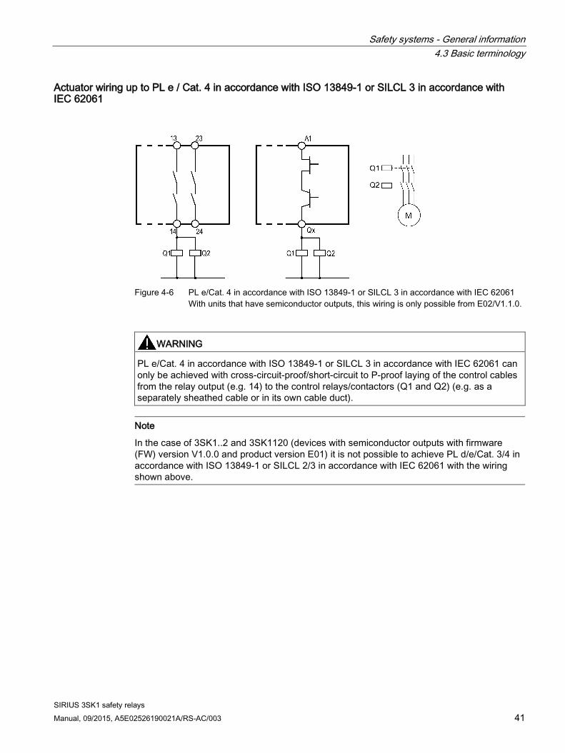
Figure 4-6 PL e/Cat. 4 in accordance with ISO 13849-1 or SILCL 3 in accordance with IEC 62061
With units that have semiconductor outputs, this wiring is only possible from E02/V1.1.0.
WARNING
PL e/Cat. 4 in accordance with ISO 13849-1 or SILCL 3 in accordance with IEC 62061 can only be achieved with cross-circuit-proof/short-circuit to P-proof laying of the control cables from the relay output (e.g. 14) to the control relays/contactors (Q1 and Q2) (e.g. as a separately sheathed cable or in its own cable duct).
Note
In the case of 3SK1..2 and 3SK1120 (devices with semiconductor outputs with firmware (FW) version V1.0.0 and product version E01) it is not possible to achieve PL d/e/Cat. 3/4 in accordance with ISO 13849-1 or SILCL 2/3 in accordance with IEC 62061 with the wiring shown above.

Safety systems - General information 4.3 Basic terminology
SIRIUS 3SK1 safety relays 42 Manual, 09/2015, A5E02526190021A/RS-AC/003
Actuator wiring up to PL e / Cat. 4 in accordance with ISO 13849-1 or SILCL 3 in accordance with IEC 62061
Figure 4-7 PL e / Cat. 4 in accordance with ISO 13849-1 or SILCL 3 in accordance with IEC 62061
Refer to the information on the function test interval in section General safety notes (Page 17).
Actuator wiring with 3RM1 up to PL e/Cat. 4 in accordance with ISO 13849-1 or SILCL 3 in accordance with IEC 62061
Figure 4-8 PL e / Cat. 4 in accordance with ISO 13849-1 or SILCL 3 in accordance with IEC 62061
Note
PL e/Cat. 4 in accordance with ISO 13849-1 or SILCL 3 in accordance with IEC 62061 can only be achieved with cross-circuit-proof/short-circuit to P-proof laying of the control cables from the relay output (e.g. 14) to the 3RM1 Failsafe motor starter (e.g. as a separately sheathed cable or in its own cable duct). Thanks to the intrinsic safety of the 3RM1 Failsafe motor starter, monitoring by the upstream 3SK1 safety relay (via feedback circuit) is not necessary here.

Safety systems - General information 4.3 Basic terminology
SIRIUS 3SK1 safety relays Manual, 09/2015, A5E02526190021A/RS-AC/003 43
Note
In the case of 3SK1..2 and 3SK1120 (devices with semiconductor outputs with firmware (FW) version V1.0.0 and product version E01) it is not possible to achieve PL d/e/Cat. 3/4 in accordance with ISO 13849-1 or SILCL 2/3 in accordance with IEC 62061 with the wiring shown above.
More detailed technical information is available in the "SIRIUS 3RM1 motor starters (http://support.automation.siemens.com/WW/view/en/66295730)" manual on the Internet.
4.3.14 Series connection of sensors
Series connection of EMERGENCY STOP command devices It is possible to connect EMERGENCY STOP command elements in series up to the highest safety level (SILCL 3 in accordance with IEC 62061, SIL 3 in accordance with IEC 61508 and PL e (Cat. 4) in accordance with ISO 13849-1), because it is assumed that only one EMERGENCY STOP is operated at a time. This ensures that errors and defects can be detected.

Safety systems - General information 4.3 Basic terminology
SIRIUS 3SK1 safety relays 44 Manual, 09/2015, A5E02526190021A/RS-AC/003
Series connection of mechanical position switches In general, position switches may be connected in series if measures ensure that several protective doors are not regularly opened simultaneously (otherwise a fault cannot be detected).
For safety level SILCL3 in accordance with IEC 62061, SIL3 in accordance with IEC 61508, and PL e (Cat. 4) in accordance with ISO 13849-1, however, they must never be connected in series, because every hazardous error must be detected (independently of the operating personnel).

SIRIUS 3SK1 safety relays Manual, 09/2015, A5E02526190021A/RS-AC/003 45
3SK1 devices 5 5.1 3SK1 standard
5.1.1 General information The safety relays of the Standard series can be configured as stand-alone devices or as an expansion solution with conventional wiring technology.
The focus of the Standard series is on: ● Single devices for simple safety applications
● Output-side expansion by means of expansion units and external wiring
● No expansion on the input side
5.1.2 Applications ● EMERGENCY OFF / EMERGENCY STOP monitoring.
● Monitoring of protective doors with electromechanical position switches, solid-state position switches, or solenoid switches.
● Monitoring of contact-free protection equipment, e.g. light arrays/light barriers, or laser scanners.
3SK1 Standard safety relays can be used in EMERGENCY OFF/EMERGENCY STOP devices in accordance with ISO 13850 and in safety circuits in accordance with VDE 0113-1 and/or DIN EN 60204-1. Depending on the external circuit, it is possible to achieve SILCL 3 in accordance with IEC 62061, SIL 3 in accordance with IEC 61508 and PL e (Cat. 4) in accordance with ISO 13849-1. The safety relays comply with DIN EN 50156-1:2004 (Electrical equipment for furnaces).
3SK1 devices 5.1 3SK1 standard
SIRIUS 3SK1 safety relays 46 Manual, 09/2015, A5E02526190021A/RS-AC/003
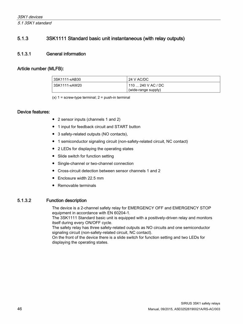
5.1.3 3SK1111 Standard basic unit instantaneous (with relay outputs)
5.1.3.1 General information
Article number (MLFB): 3SK1111-xAB30 24 V AC/DC 3SK1111-xAW20 110 ... 240 V AC / DC
(wide-range supply) (x) 1 = screw-type terminal; 2 = push-in terminal
Device features: ● 2 sensor inputs (channels 1 and 2)
● 1 input for feedback circuit and START button
● 3 safety-related outputs (NO contacts),
● 1 semiconductor signaling circuit (non-safety-related circuit, NC contact)
● 2 LEDs for displaying the operating states
● Slide switch for function setting
● Single-channel or two-channel connection
● Cross-circuit detection between sensor channels 1 and 2
● Enclosure width 22.5 mm
● Removable terminals
5.1.3.2 Function description The device is a 2-channel safety relay for EMERGENCY OFF and EMERGENCY STOP equipment in accordance with EN 60204-1. The 3SK1111 Standard basic unit is equipped with a positively-driven relay and monitors itself during every ON/OFF cycle. The safety relay has three safety-related outputs as NO circuits and one semiconductor signaling circuit (non-safety-related circuit, NC contact). On the front of the device there is a slide switch for function setting and two LEDs for displaying the operating states.

3SK1 devices 5.1 3SK1 standard
SIRIUS 3SK1 safety relays Manual, 09/2015, A5E02526190021A/RS-AC/003 47
5.1.3.3 Design
① Top cover flap ② Top cover flap; internal inscription ③ Display LEDs ④ Slide switch ⑤ Bottom cover flap ⑥ Bottom cover flap; internal inscription ⑦ DataMatrix code ⑧ Device identification label

3SK1 devices 5.1 3SK1 standard
SIRIUS 3SK1 safety relays 48 Manual, 09/2015, A5E02526190021A/RS-AC/003
5.1.3.4 Terminal assignment
Terminal Explanation A1 L+ A2 N- IN1 Sensor channel 1 IN2 Sensor channel 2 IN3 Non-floating sensor evaluation 1) INF/S Feedback circuit/START button T1 Test output 1 (for IN1) T2 Test output 2 (for IN2) T3 Test output 3 (for IN3) 1) T4 Test output 4 (for INF/S) 13 - 14 23 - 24 33 - 34
Safety-related outputs (NO contact, relay contact)
41 - 42 Semiconductor signaling circuits (NC contact, relay contact) Floating: Sensors T1/IN1 and T2/IN2
Jumper T3/IN3 Non-floating Sensors IN1 and IN31)
Jumper T2/IN2 1) For 24 V AC/DC variant only
5.1.3.5 Inputs The device has three or four inputs for safe signal processing: IN1, IN2 or IN3 (only 24 V devices for connecting floating sensors) INF/S:
The inputs IN1 and IN2 can only be operated in two-channel mode with cross-circuit detection. Single-channel activation is only possible via the supply voltage connection (A1). In this case, circuits T1/IN1, T2/IN2 and T3/IN3 (24 V devices only) must be jumpered.
You can find additional information on single-channel sensor connection in the Typical circuits (Page 120) section.
Voltage variant 24 V: Connecting floating sensors:
When floating sensors are used, sensor inputs T1/IN1 and T2/IN2 must be used and T3/IN3 must additionally be jumpered for two-channel sensor connection.
Connecting non-floating sensors:
With non-floating sensors, cross-circuit detection must be deactivated. This is implemented by the following pin assignment on the 3SK1111-.AB30:
IN1 and IN3 must be used as the input terminal for the two-channel non-floating sensor. In addition, T2/IN2 must be jumpered.

3SK1 devices 5.1 3SK1 standard
SIRIUS 3SK1 safety relays Manual, 09/2015, A5E02526190021A/RS-AC/003 49
Voltage variant 110 V ... 240 V AC/DC: Only floating sensors can be connected to the 3SK1111-.AW20 device version.
The 2-channel sensor is connected via T1/IN1 and T2/IN2.
5.1.3.6 Outputs The safety relay has the following outputs:
● Safety-related outputs (relays), NO contacts: 13/14, 23/24, 33/34
● Non-safety-related outputs (semiconductor signaling circuit; relays), NC contacts: 41/42
5.1.3.7 Display of the operating state Two LEDs and a slide switch indicate the operating state and functioning of the device:
● DEVICE
● OUT
LED displays
LED Operation DEVICE OUT Line sup-
ply Sensor START button Safety-related
output Green Green ON Not pressed Pressed Closed Green OFF Pressed --- Open Green OFF Not pressed --- Open
Error OFF OFF Cross-circuit or no power supply Open
5.1.3.8 Function setting
Setting the functions
Slide switch Start
AUTO Autostart MONITORED Monitored start
In the delivery state, the slide switch is at the bottom (monitored start).

3SK1 devices 5.1 3SK1 standard
SIRIUS 3SK1 safety relays 50 Manual, 09/2015, A5E02526190021A/RS-AC/003
State diagrams 3SK1111

3SK1 devices 5.1 3SK1 standard
SIRIUS 3SK1 safety relays Manual, 09/2015, A5E02526190021A/RS-AC/003 51

3SK1 devices 5.1 3SK1 standard
SIRIUS 3SK1 safety relays 52 Manual, 09/2015, A5E02526190021A/RS-AC/003
5.1.4 3SK1112 Standard basic unit instantaneous (with semiconductor outputs)
5.1.4.1 General information
Article number MLFB: 3SK1112-xBB40 24 V DC (x) 1 = screw-type terminal; 2 = push-in terminal
Device features: ● 4-way DIP switch for function setting (parameterization)
● SET/RESET button
● 4 LEDs for status and function display
● 2 sensor inputs (channels 1 and 2)
● 1 input (cascading circuit)
● 1 input (START pushbutton circuit)
● 1 input (feedback circuit)
● 2 test outputs
● 2 semiconductor outputs
● 1 semiconductor signaling circuit
● Enclosure width 22.5 mm
● Removable terminals
WARNING
Continuous operation
Devices up to E01/V1.0.0: In continuous operation for PL e/Cat. 4 in accordance with ISO 13849-1 or SILCL 3 in accordance with IEC 62061, the key safety values apply where the function test interval (state change of the outputs) ≤ 1 year.
Devices from E02/V1.1.0: In continuous operation for PL e/Cat. 4 in accordance with ISO 13849-1 or SILCL 3 in accordance with IEC 62061, the key safety values apply where the function test interval (state change of the outputs) ≤ 20 years.

3SK1 devices 5.1 3SK1 standard
SIRIUS 3SK1 safety relays Manual, 09/2015, A5E02526190021A/RS-AC/003 53
5.1.4.2 Function description The 3SK1112 safety relay has two safety-related semiconductor outputs and one non-safety-related signaling circuit. On the front of the device there is a 4-way DIP switch for function setting and 4 LEDs for status and function display. The SET/RESET button is used to load function settings and to restart the device (reset). On commissioning, the device runs through a self-test. This checks that the internal electronics and firmware are functioning correctly. All internal safety-critical parts of the circuit are cyclically monitored for faults during operation. The semiconductor outputs cyclically run through a light/dark test for up to 2.5 ms (dynamically) to verify their correct functioning.

3SK1 devices 5.1 3SK1 standard
SIRIUS 3SK1 safety relays 54 Manual, 09/2015, A5E02526190021A/RS-AC/003
5.1.4.3 Design
① Top cover flap ② Top cover flap; internal inscription ③ Display LEDs ④ DIP switch ⑤ SET/RESET button ⑥ Bottom cover flap ⑦ Bottom cover flap; internal inscription ⑧ DataMatrix code ⑨ Device identification label

3SK1 devices 5.1 3SK1 standard
SIRIUS 3SK1 safety relays Manual, 09/2015, A5E02526190021A/RS-AC/003 55
5.1.4.4 Terminal assignment
Terminal Explanation A1 + A2 - IN1 Sensor channel 1 IN2 Sensor channel 2 INS START pushbutton circuit INF Feedback circuit INK Cascading circuit T1 Test output 1 (for IN1) T2 Test output 2 (for IN2, INF) Q1 Semiconductor output 1 (switching to P potential, 24 V DC) Q2 Semiconductor output 2 (switching to P potential, 24 V DC) QM1 Semiconductor signaling circuit 1 (switching to P potential, 24 V DC)
5.1.4.5 Inputs The device has five inputs for safe signal processing: IN1, IN2, INS, INF, INK: ● IN1: sensor input channel 1 ● IN2: sensor input channel 2 ● INS: START pushbutton circuit (start after rising and falling edge) ● INF: feedback circuit (checked for closed state: before switching on) ● INK: cascading circuit (cascading input/normal switching duty) ● The cascading circuit is AND-connected with the IN1 and IN2 sensor inputs. ● START button circuit and cascading circuit are activated with a static +24 V DC signal. ● With cross-circuit detection activated, the following inputs are checked for cross-circuits
and short-circuits to P: IN1/T1 to IN2/T2 and INF/T2. The inputs then receive their supplies from the test outputs T1 and T2.
● If "without cross-circuit detection" is set on the device, inputs IN1 and IN2 are not checked for cross-circuits. Inputs IN1 and IN2 must not be supplied via T1/T2 here, otherwise a fault will be generated via input INF. It is therefore essential that inputs IN1 and IN2 are supplied via an external + 24 V DC current source from which the device is also supplied.
● If the unit is parameterized to 2 x 1-channel with DIP switch 3, the sensor circuit that is not used (T1/IN1 or T2/IN2) must be bypassed.
Note Observe the following special points during commissioning of the 3SK1112 safety relay:
The cascading input must be connected to terminal A1 if it is not to be used.
Monitoring of the feedback circuits is not optional.

3SK1 devices 5.1 3SK1 standard
SIRIUS 3SK1 safety relays 56 Manual, 09/2015, A5E02526190021A/RS-AC/003
5.1.4.6 Outputs The safety relay has the following outputs:
● Q1, Q2: safety-related semiconductor outputs with dynamic monitoring, switching to P potential
● QM1: non-safety-related semiconductor signaling circuit, switching to P potential
The safety-related semiconductor outputs and the safety-related semiconductor signaling circuit are short-circuit-proof.
5.1.4.7 Display of the operating state Four LEDs and one DIP switch indicate the operating state and functioning of the device:
● (1) DEVICE
● (2) OUT
● (3) IN
● (4) SF
The four LEDs show the following:
● Operating mode: Diagnostics
● Configuration mode: DIP setting
For an explanation of the operating state display, see Section Display and diagnostics (Page 197)

3SK1 devices 5.1 3SK1 standard
SIRIUS 3SK1 safety relays Manual, 09/2015, A5E02526190021A/RS-AC/003 57
5.1.4.8 Function setting
Table 5- 1 DIP switch
Switch position: left Schematic DIP switch No. Switch position: right Autostart
1 Monitored start Cross-circuit detection deactivated
2 Cross-circuit detection activated
2 x single-channel sensor connection
3 1 x two-channel sensor connection
Start-up test ON 4 Start-up test OFF
In the delivery state, all the DIP switches are in switch position: right.
Table 5- 2 SET/RESET button
Function of the SET/RESET button
Status of the indicating LEDs Function
SET "DEVICE" LED flashing yellow
• Press key for about 1 s The parameterization is loaded
RESET "DEVICE" LED red • Press key for about 1 s => The device restarts without the supply voltage having to be switched off
"DEVICE" LED flashing green yellow "SF" LED red
Note
The SET/RESET pushbutton only triggers a reset for the device on which the button is pressed.

3SK1 devices 5.1 3SK1 standard
SIRIUS 3SK1 safety relays 58 Manual, 09/2015, A5E02526190021A/RS-AC/003
State diagrams 3SK1112

3SK1 devices 5.2 3SK1 Advanced
SIRIUS 3SK1 safety relays Manual, 09/2015, A5E02526190021A/RS-AC/003 59
5.2 3SK1 Advanced
5.2.1 General information The safety relays of the Advanced device series comprise basic devices and input and output expansions. The Advanced safety relays can be connected by means of a 3ZY12 device connector. When configuring the system, it must be ensured that input expansions are always mounted on the left, and output expansions (3SK121 or 3RM1 Failsafe motor starter) on the right of the basic unit. For control supply voltages of 110 ... 240 V AC/DC, the Advanced device series can be supplied with the necessary 24 V DC voltage from the 3SK1230 power supply (which must be positioned on the extreme left in the system).
The focus of the Advanced relay series is on: ● Single devices that can be flexibly parameterized
● Expandability using 3ZY12 device connector on both input and output side
● Basic units with time-delayed safety-related outputs
5.2.2 Applications ● EMERGENCY OFF / EMERGENCY STOP monitoring.
● Monitoring of protective doors with electromechanical position switches, solid-state position switches, or solenoid switches.
● Monitoring of contact-free protection equipment, e.g. light arrays/light barriers, or laser scanners.
The 3SK1 safety relays Advanced can be used in EMERGENCY OFF and EMERGENCY STOP devices in accordance with EN 60204-1 and in safety circuits in accordance with VDE 0113-1 and/or EN 60204-1, e.g. in circuits in which controlled shutdown, STOP Category 1, is necessary. Depending on the external circuit, it is possible to achieve SILCL 3 in accordance with IEC 62061, SIL 3 in accordance with IEC 61508 and PL e (Cat. 4) in accordance with ISO 13849-1. The safety relays comply with DIN EN 50156-1:2004 (Electrical equipment for furnaces). You can use the 3SK1 safety relays Advanced to achieve two-hand switching applications up to type IIIc in compliance with EN 574:1996+A1:2008.

3SK1 devices 5.2 3SK1 Advanced
SIRIUS 3SK1 safety relays 60 Manual, 09/2015, A5E02526190021A/RS-AC/003
5.2.3 General device features
Device properties: ● 4-way DIP switch for function setting (parameterization)
● SET/RESET button
● 4 LEDs for status and function display
● 2 sensor inputs (channels 1 and 2)
● 1 input (cascading circuit)
● 1 input (START pushbutton circuit)
● NO contact/NC contact evaluation via external jumper (T1/PAR)
● Connecting interface for 3ZY12 device connectors
● Removable terminals
5.2.4 Function description There is a 4-way DIP switch for function setting and 4 LEDs for status and function display on the front of the 3SK1 Advanced basic units. A SET/RESET button can be used to load function settings and to perform a device restart (reset). On commissioning, the devices runs a self-test in which the internal electronics and firmware are checked for correct functioning. All internal parts of the circuit are cyclically monitored for faults during operation. In the case of units with semiconductor outputs, they cyclically run through a light/dark test for up to 2.5 ms (dynamically) to verify their correct functioning. The safety relays can be expanded using 3ZY12 device connectors with input and output expansions.
3SK1 Advanced basic unit time-delayed only:
These basic units have two time-delayed and two instantaneous safety-related outputs (NO circuits) or outputs switching to P potential.
Four LEDs and one DIP switch indicate the operating state and functioning of the device:
● (1) DEVICE
● (2) OUT
● (3) IN
● (4) SF
The four LEDs show the following:
● Operating mode: Diagnostics
● Configuration mode: DIP setting
For an explanation of the operating state display, see Section Display and diagnostics (Page 197)

3SK1 devices 5.2 3SK1 Advanced
SIRIUS 3SK1 safety relays Manual, 09/2015, A5E02526190021A/RS-AC/003 61
5.2.5 Functions
Table 5- 3 DIP switch
Switch position: left Schematic DIP switch No. Switch position: right Autostart
1 Monitored start Cross-circuit detection deactivated
2 Cross-circuit detection activated
2 x single-channel sensor connection
3 1 x two-channel sensor connection
Start-up test ON 4 Start-up test OFF
In the delivery state, all the DIP switches are in switch position: right.
Terminal parameterization: Jumper on terminals T1/PAR = NO/NC evaluation
Table 5- 4 SET/RESET button
Function of the SET/RESET button
Status of the indicating LEDs Function
SET "DEVICE" LED flashing yellow • Press key for about 1 s The parameterization is loaded
RESET "DEVICE" LED red • Press key for about 1 s => The device restarts without the supply voltage having to be switched off
"DEVICE" LED flashing green yellow "SF" LED red
Note
The SET/RESET pushbutton only triggers a reset for the device on which the button is pressed.

3SK1 devices 5.2 3SK1 Advanced
SIRIUS 3SK1 safety relays 62 Manual, 09/2015, A5E02526190021A/RS-AC/003
Potentiometer for time setting Potentiometer for infinite time setting of the time-delayed safety-related outputs on the Advanced basic units (with time-delayed safety-related outputs).
● 3SK112.-.CB41 setting range: 0.05 ... 3 s
● 3SK112.-.CB42 setting range: 0.5 ... 30 s
● 3SK112.-.CB44 setting range: 5 ... 300 s
Note
The delay time ends when the voltage is disconnected. The time-delayed contacts change switch position.
Using the cascading input The cascading input must be controlled with a 24 V DC signal. The voltage source of the 24 V DC signal must correspond to the voltage source of the safety relay's supply voltage (A1).
Note Observe the following during commissioning of 3SK1 Advanced safety relays:
The cascading input must be connected to terminal A1 if it is not to be used.
Monitoring of the feedback circuits is not optional.
"2 x single-channel" parameterization If the unit is parameterized to 2 x 1-channel with DIP switch 3, the sensor circuit that is not used (T1/IN1 or T2/IN2) must be bypassed.

3SK1 devices 5.2 3SK1 Advanced
SIRIUS 3SK1 safety relays Manual, 09/2015, A5E02526190021A/RS-AC/003 63
5.2.6 3SK1121 Advanced basic unit instantaneous (with relay outputs)
5.2.6.1 Device features
Article number (MLFB): 3SK1121-xAB40 24 V DC (x) 1 = screw-type terminal; 2 = push-in terminal
5.2.6.2 Function description The 3SK1121 Advanced basic unit has three safety-related relay outputs and one non-safety-related signaling circuit.

3SK1 devices 5.2 3SK1 Advanced
SIRIUS 3SK1 safety relays 64 Manual, 09/2015, A5E02526190021A/RS-AC/003
5.2.6.3 Design
① Top cover flap ② Top cover flap; internal inscription ③ Display LEDs ④ DIP switch ⑤ SET/RESET button ⑥ Bottom cover flap ⑦ Bottom cover flap; internal inscription ⑧ DataMatrix code ⑨ Device identification label

3SK1 devices 5.2 3SK1 Advanced
SIRIUS 3SK1 safety relays Manual, 09/2015, A5E02526190021A/RS-AC/003 65
5.2.6.4 Terminal assignment
Terminal Explanation A1 + A2 - IN1 Sensor channel 1 IN2 Sensor channel 2 PAR NO contact/NC contact evaluation INS START pushbutton circuit INF Feedback circuit INK Cascading circuit T1 Test output 1 (for IN1, PAR) T2 Test output 2 (for IN2, INF) 13 - 14 23 - 24 33 - 34
Safety-related outputs (NO contact, relay contact)
41 - 42 Semiconductor signaling circuits (NC contact, relay contact)
State diagram 3SK1121

3SK1 devices 5.2 3SK1 Advanced
SIRIUS 3SK1 safety relays 66 Manual, 09/2015, A5E02526190021A/RS-AC/003
5.2.7 3SK1121 Advanced basic unit time-delayed (with relay outputs)
5.2.7.1 Device features
Article number (MLFB): 3SK1121-xCB4y 24 V DC (x) 1 = screw-type terminal; 2 = push-in terminal
(y) time delay 1 = 0.05 ... 3 s; 2 = 0.5 ... 30 s; 4 = 5 ... 300 s
Additional / alternative device characteristics ● 2 instantaneous safety-related outputs (NO contacts)
● 2 time-delayed safety-related outputs (NO contacts),
● Potentiometer for setting the delay time
● Time function: With OFF-delay

3SK1 devices 5.2 3SK1 Advanced
SIRIUS 3SK1 safety relays Manual, 09/2015, A5E02526190021A/RS-AC/003 67
5.2.7.2 Design
① Top cover flap ② Top cover flap; internal inscription ③ Display LEDs ④ Potentiometer for setting the delay time ⑤ DIP switch ⑥ SET/RESET button ⑦ Bottom cover flap ⑧ Bottom cover flap; internal inscription ⑨ DataMatrix code ⑩ Device identification label

3SK1 devices 5.2 3SK1 Advanced
SIRIUS 3SK1 safety relays 68 Manual, 09/2015, A5E02526190021A/RS-AC/003
5.2.7.3 Terminal assignment
Terminal Explanation A1 + A2 - IN1 Sensor channel 1 IN2 Sensor channel 2 PAR NO contact/NC contact evaluation INS START pushbutton circuit INF Feedback circuit INK Cascading circuit T1 Test output 1 (for IN1, PAR) T2 Test output 2 (for IN2, INF) 13 - 14 Instantaneous safety-related output 1 (NO contact, relay contact) 23 - 24 Instantaneous safety-related output 2 (NO contact, relay contact) 37 - 38 Delayed safety-related output 1 (NO contact, relay contact) 47 - 48 Delayed safety-related output 2 (NO contact, relay contact)
State diagrams 3SK1121-xCB4y

3SK1 devices 5.2 3SK1 Advanced
SIRIUS 3SK1 safety relays Manual, 09/2015, A5E02526190021A/RS-AC/003 69

3SK1 devices 5.2 3SK1 Advanced
SIRIUS 3SK1 safety relays 70 Manual, 09/2015, A5E02526190021A/RS-AC/003
5.2.8 3SK1122 Advanced basic unit instantaneous (with semiconductor outputs)
5.2.8.1 Device features
Article number (MLFB): 3SK1122-xAB40 24 V DC (x) 1 = screw-type terminal; 2 = push-in terminal
Additional or alternative device features ● 3 safety-related semiconductor outputs
● 1 semiconductor signaling circuit
WARNING
Continuous operation
Devices up to E01/V1.0.0: In continuous operation for PL e/Cat. 4 in accordance with ISO 13849-1 or SILCL 3 in accordance with IEC 62061, the key safety values apply where the function test interval (state change of the outputs) ≤ 1 year.
Devices from E02/V1.1.0: In continuous operation for PL e/Cat. 4 in accordance with ISO 13849-1 or SILCL 3 in accordance with IEC 62061, the key safety values apply where the function test interval (state change of the outputs) ≤ 20 years.

3SK1 devices 5.2 3SK1 Advanced
SIRIUS 3SK1 safety relays Manual, 09/2015, A5E02526190021A/RS-AC/003 71
5.2.8.2 Design
① Top cover flap ② Top cover flap; internal inscription ③ Display LEDs ④ DIP switch ⑤ SET/RESET button ⑥ Bottom cover flap ⑦ Bottom cover flap; internal inscription ⑧ DataMatrix code ⑨ Device identification label

3SK1 devices 5.2 3SK1 Advanced
SIRIUS 3SK1 safety relays 72 Manual, 09/2015, A5E02526190021A/RS-AC/003
5.2.8.3 Terminal assignment
Terminal Explanation A1 + A2 - IN1 Sensor channel 1 IN2 Sensor channel 2 PAR NO contact/NC contact evaluation INS START pushbutton circuit INF Feedback circuit INK Cascading circuit T1 Test output 1 (for IN1, PAR) T2 Test output 2 (for IN2, INF) Q1 Safety-related output 1
(switching to P potential, 24 V DC) Q2 Safety-related output 2
(switching to P potential, 24 V DC) Q3 Safety-related output 3
(switching to P potential, 24 V DC) QM1 Semiconductor signaling circuit 1
(switching to P potential, 24 V DC)

3SK1 devices 5.2 3SK1 Advanced
SIRIUS 3SK1 safety relays Manual, 09/2015, A5E02526190021A/RS-AC/003 73
State diagrams 3SK1122-xAB40

3SK1 devices 5.2 3SK1 Advanced
SIRIUS 3SK1 safety relays 74 Manual, 09/2015, A5E02526190021A/RS-AC/003
5.2.9 3SK1122 Advanced basic unit time-delayed (with semiconductor outputs)
5.2.9.1 Device features
Article number (MLFB): 3SK1122-xCB4y 24 V DC (x) 1 = screw-type terminal; 2 = push-in terminal
(y) time delay 1 = 0.05 ... 3 s; 2 = 0.5 ... 30 s; 4 = 5 ... 300 s
Additional / alternative device characteristics ● 2 instantaneous semiconductor outputs
● 2 time-delayed semiconductor outputs
● Potentiometer for setting the delay time
● Time function: With OFF-delay
WARNING
Continuous operation
Devices up to E01/V1.0.0: In continuous operation for PL e/Cat. 4 in accordance with ISO 13849-1 or SILCL 3 in accordance with IEC 62061, the key safety values apply where the function test interval (state change of the outputs) ≤ 1 year.
Devices from E02/V1.1.0: In continuous operation for PL e/Cat. 4 in accordance with ISO 13849-1 or SILCL 3 in accordance with IEC 62061, the key safety values apply where the function test interval (state change of the outputs) ≤ 20 years.

3SK1 devices 5.2 3SK1 Advanced
SIRIUS 3SK1 safety relays Manual, 09/2015, A5E02526190021A/RS-AC/003 75
5.2.9.2 Design
① Top cover flap ② Top cover flap; internal inscription ③ Display LEDs ④ Potentiometer for setting the delay time ⑤ DIP switch ⑥ SET/RESET button ⑦ Bottom cover flap ⑧ Bottom cover flap; internal inscription ⑨ DataMatrix code ⑩ Device identification label

3SK1 devices 5.2 3SK1 Advanced
SIRIUS 3SK1 safety relays 76 Manual, 09/2015, A5E02526190021A/RS-AC/003
5.2.9.3 Terminal assignment
Terminal Explanation A1 + A2 - IN1 Sensor channel 1 IN2 Sensor channel 2 PAR NO contact/NC contact evaluation INS START pushbutton circuit INF Feedback circuit INK Cascading circuit / normal switching duty T1 Test output 1 (for IN1, PAR) T2 Test output 2 (for IN2, INF) Q1 Instantaneous safety-related output 1
(switching to P potential, 24 V DC) Q2 Instantaneous safety-related output 2
(switching to P potential, 24 V DC) Qt1 Time-delayed safety-related output 1
(switching to P potential, 24 V DC) Qt2 Time-delayed safety-related output 2
(switching to P potential, 24 V DC)

3SK1 devices 5.2 3SK1 Advanced
SIRIUS 3SK1 safety relays Manual, 09/2015, A5E02526190021A/RS-AC/003 77
State diagrams 3SK1122-xCB4y

3SK1 devices 5.2 3SK1 Advanced
SIRIUS 3SK1 safety relays 78 Manual, 09/2015, A5E02526190021A/RS-AC/003
5.2.10 3SK1120 Advanced basic unit instantaneous (with semiconductor outputs)
5.2.10.1 Device features
Article number (MLFB): 3SK1120-xAB40 24 V DC (x) 1 = screw-type terminal; 2 = push-in terminal
Additional or alternative device features ● 1 safety-related semiconductor output
● The following design variants are possible for the 3SK1120 Advanced basic unit:
– In operation without using device connectors, up to PL e/Cat. 4 in accordance with ISO 13849-1 or SILCL 3 in accordance with IEC 62061 can be achieved for devices from E02/V 1.1.0.
WARNING
Operation without using device connectors for E01/V1.0.0 devices
In operation without using device connectors, up to PL c / Cat. 2 in accordance with ISO 13849-1 or SILCL 2 in accordance with IEC 62061 can be achieved.
– Operation using device connectors
In operation using device connectors and using at least one output expansion (3SK1211, 3SK1213) or one 3RM1 Failsafe motor starter, up to PL e/Cat. 4 in accordance with ISO 13849-1 or SILCL 3 in accordance with IEC 62061 can be achieved.
WARNING
Continuous operation
Devices up to E01/V1.0.0: In continuous operation for PL e/Cat. 4 in accordance with ISO 13849-1 or SILCL 3 in accordance with IEC 62061, the key safety values apply where the function test interval (state change of the outputs) ≤ 1 year.
Devices from E02/V1.1.0: In continuous operation for PL e/Cat. 4 in accordance with ISO 13849-1 or SILCL 3 in accordance with IEC 62061, the key safety values apply where the function test interval (state change of the outputs) ≤ 20 years.

3SK1 devices 5.2 3SK1 Advanced
SIRIUS 3SK1 safety relays Manual, 09/2015, A5E02526190021A/RS-AC/003 79
5.2.10.2 Design
① Top cover flap ② Top cover flap; internal inscription ③ Display LEDs ④ DIP switch ⑤ SET/RESET button ⑥ Bottom cover flap ⑦ Bottom cover flap; internal inscription ⑧ DataMatrix code ⑨ Device identification label

3SK1 devices 5.2 3SK1 Advanced
SIRIUS 3SK1 safety relays 80 Manual, 09/2015, A5E02526190021A/RS-AC/003
5.2.10.3 Terminal assignment
Terminal Explanation A1 + A2 - IN1 Sensor channel 1 IN2 Sensor channel 2 PAR NO contact/NC contact evaluation INS START pushbutton circuit INF Feedback circuit INK Cascading circuit T1 Test output 1 (for IN1, PAR) T2 Test output 2 (for IN2, INF) Q1 Safety-related output 1
(switching to P potential, 24 V DC)

3SK1 devices 5.2 3SK1 Advanced
SIRIUS 3SK1 safety relays Manual, 09/2015, A5E02526190021A/RS-AC/003 81
5.2.10.4 Status diagrams
State diagrams 3SK1120-xAB40

3SK1 devices 5.3 3SK1 output expansions
SIRIUS 3SK1 safety relays 82 Manual, 09/2015, A5E02526190021A/RS-AC/003
5.3 3SK1 output expansions
5.3.1 Applications The 3SK1 output expansions are used to expand the safety-related outputs. The maximum achievable Performance Level PL/Cat. in accordance with ISO 13849-1, SILCL in accordance with IEC 62061, SIL in accordance with IEC 61508 corresponds to the Performance Level PL and SIL of the basic unit when the external wiring (connection between basic unit and output expansion) is configured as fail-safe (e.g. basic unit and output expansion are connected using 3ZY12 device connector). The output expansions can be activated via the supply voltage (A1/A2) or using 3ZY12 device connectors1). 1) For 24 V DC variant only
Note
If expansion units are controlled via the 3ZY12 device connector, additional feeding of the control supply voltage (A1/A2) at one of the output expansions leads to a fault in the system configuration.
Note Use of the output expansions on 3ZY12 device connectors
You can switch between instantaneous or delayed control of the basic unit using the slide switch of the output expansion (see also the chapter "System configuration rules (Page 107)").
Note Using the output expansions with conventional wiring
The slide switch has no function here.
If you require Stop category 1 outputs for the output expansion, terminals A1/A2 of the output expansion must be connected to outputs 38 or 48 on 3SK1 basic units with relay outputs or to Q1t/Q2t (in the case of 3SK1 with semiconductor outputs).

3SK1 devices 5.3 3SK1 output expansions
SIRIUS 3SK1 safety relays Manual, 09/2015, A5E02526190021A/RS-AC/003 83
5.3.2 Function description The operating state of the 3SK1 output expansions is displayed on the DEVICE LED.
The 3SK1211 output expansions (4RO) have four safety-related outputs as NO circuits, and the 3SK1213 output expansions (3RO) have three. They each have one positively-driven NC circuit. The output expansions can be activated via any output of the basic unit via (A1). The NC circuit 51/52 of 3SK1211 (4RO) or 41/42 of 3SK1213 (3RO) is used for monitoring the output expansions.
In the 24 V DC variants, the expansion units can be activated and evaluated via the 3ZY12 device connectors.
5.3.3 Display of the operating state
Display of the operating state The operating state and functioning of the device are indicated by an LED:
● (1) DEVICE
Operating states LED State Meaning DEVICE Control supply voltage Safety-related outputs OFF OFF Open Green ON Closed
5.3.4 Function setting
Setting the activation (slide switch only for 24 V variants) The interface input for activating the output expansion can be selected using a slide switch on the front of the device.
Slide switch
Interface input
Top Outputs switch with time delay (as in basic unit) Bottom Outputs switch instantaneously
When using an instantaneous basic unit, the slide switch must be in the instantaneous position (bottom).

3SK1 devices 5.3 3SK1 output expansions
SIRIUS 3SK1 safety relays 84 Manual, 09/2015, A5E02526190021A/RS-AC/003
5.3.5 Output expansion 3SK1211
5.3.5.1 Device features
Article number (MLFB): 3SK1211-xBB00 24 V AC 3SK1211-xBB40 24 V DC 3SK1211-xBW20 110 ... 240 V AC / DC (wide-range supply) (x) 1 = screw-type terminal; 2 = push-in terminal
Supply:
24 V AC:
● Activation via 24 V transformer is possible
24 V DC:
● An SELV / PELV power supply must be used for the infeed
110 ... 240 V AC/DC:
● Direct line supply connection L/N
Device properties: ● Slide switch for selecting the activation type (time-delayed / instantaneous)*
● 1 LED for status display
● 4 safety-related outputs (NO contacts),
● 1 NC circuit as feedback contact for the 3SK1211 output expansion to the upstream basic unit
● 3ZY12* device connectors
● Enclosure width 22.5 mm
● Removable terminals
* For 24 V DC variant only

3SK1 devices 5.3 3SK1 output expansions
SIRIUS 3SK1 safety relays Manual, 09/2015, A5E02526190021A/RS-AC/003 85
5.3.5.2 Design of 3SK1211-.B..0
① Top cover flap ② Top cover flap; internal inscription ③ Display LEDs ④ Bottom cover flap ⑤ Bottom cover flap; internal inscription ⑥ DataMatrix code ⑦ Device identification label
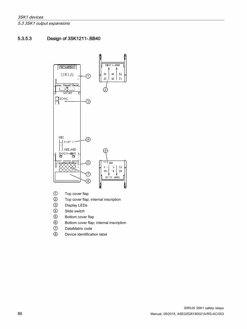
3SK1 devices 5.3 3SK1 output expansions
SIRIUS 3SK1 safety relays 86 Manual, 09/2015, A5E02526190021A/RS-AC/003
5.3.5.3 Design of 3SK1211-.BB40
① Top cover flap ② Top cover flap; internal inscription ③ Display LEDs ④ Slide switch ⑤ Bottom cover flap ⑥ Bottom cover flap; internal inscription ⑦ DataMatrix code ⑧ Device identification label

3SK1 devices 5.3 3SK1 output expansions
SIRIUS 3SK1 safety relays Manual, 09/2015, A5E02526190021A/RS-AC/003 87
5.3.5.4 Terminal assignment
Terminal Explanation A1 + (L+ for 3SK1211-.BW20) A2 - (N- for 3SK1211-.BW20) 13 - 14 Safety-related output 1 (NO contact, relay contact) 23 - 24 Safety-related output 2 (NO contact, relay contact) 33 - 34 Safety-related output 3 (NO contact, relay contact) 43 - 44 Safety-related output 4 (NO contact, relay contact) 51 - 52 NC circuit as feedback contact (NC, relay contact)

3SK1 devices 5.3 3SK1 output expansions
SIRIUS 3SK1 safety relays 88 Manual, 09/2015, A5E02526190021A/RS-AC/003
5.3.6 Output expansion 3SK1213
5.3.6.1 Device features
Article number (MLFB): 3SK1213-xAB40 24 V DC 3SK1213-xAJ20 115 V AC 3SK1213-xAL20 230 V AC (x) 1 = screw-type terminal; 2 = spring-loaded terminal
Supply:
24 V DC:
● An SELV / PELV power supply must be used for the infeed
115 V AC and 230 V AC
● Direct line supply connection L/N
Device properties: ● Slide switch for selecting the activation type (time-delayed / instantaneous)*
● 1 LED for status display
● 3 safety-related outputs (NO contacts),
● 1 NC circuit as feedback contact for the 3SK1213 output expansion for the upstream basic unit
● 3ZY12* device connectors
● Enclosure width 90 mm
● Removable terminals
* For 24 V DC variant only
Using 3ZY12 device connectors The 3SK1213 output expansion must always be terminated with a device termination connector set for the 3SK1 safety relay, size > 45 mm (3ZY1212-0FA01). Expansion on the right-hand side is then no longer possible.

3SK1 devices 5.3 3SK1 output expansions
SIRIUS 3SK1 safety relays Manual, 09/2015, A5E02526190021A/RS-AC/003 89
5.3.6.2 Design of 3SK1213-.AB40
① Top cover flap ② Display LEDs ③ Slide switch ④ DataMatrix code ⑤ Bottom cover flap ⑥ Device identification label ⑦ Screw-type terminals ⑧ Spring-loaded terminals

3SK1 devices 5.3 3SK1 output expansions
SIRIUS 3SK1 safety relays 90 Manual, 09/2015, A5E02526190021A/RS-AC/003
5.3.6.3 Design of 3SK1213-.A.20
① Top cover flap ② Display LEDs ③ DataMatrix code ④ Bottom cover flap ⑤ Device identification label ⑥ Screw-type terminals ⑦ Spring-loaded terminals
5.3.6.4 Terminal assignment
Terminal Description A1 + A2 - 13 - 14 Safety-related output 1 (NO contact, relay contact) 23 - 24 Safety-related output 2 (NO contact, relay contact) 33 - 34 Safety-related output 3 (NO contact, relay contact) 41 - 42 NC circuit as feedback contact (NC, relay contact)

3SK1 devices 5.3 3SK1 output expansions
SIRIUS 3SK1 safety relays Manual, 09/2015, A5E02526190021A/RS-AC/003 91
5.3.7 3RM1 Failsafe motor starters 3RM1 Failsafe motor starters can be used wherever combinations of contactors and overload relays were previously used.
3RM1 Failsafe motor starters are used in the following areas, for example:
● Conveyor technology
● Logistics systems
● Production machines
● Machine tools
● Small elevators
Thanks to the additional functionality of safety-related shutdown, the 3RM11 Failsafe and 3RM13 Failsafe motor starter variants are ideally suited to safety-related applications in the 3SK1 system up to SILCL 3 in accordance with IEC 62061 and PL e/Cat. 4 in accordance with ISO 13849-1.
The maximum achievable Performance Level PL/Cat. in accordance with ISO 13849-1, SILCL in accordance with IEC 62061, SIL in accordance with IEC 61508 corresponds to the Performance Level PL and SIL of the 3SK1 basic unit when the external wiring (connection between basic unit and output expansion) is configured as fail-safe (e.g. basic unit and 3RM1 Failsafe motor starter are connected using 3ZY12 device connector).
3RM1 Failsafe motor starters can be controlled via the supply voltage (A1/A2) or via 3ZY12 device connectors (24 V DC variant only).
Note
If expansion units are controlled via the 3ZY12 device connector, additional feeding of the control supply voltage (A1/A2) at one of the output expansions leads to a fault in the system configuration.
Note
In the configuration with a 3SK1 Advanced basic unit on a 3ZY12 device connector, 3RM1 Failsafe motor starters can only be controlled by the instantaneous enable signal of the 3SK1 unit. If control of the 3RM1 Failsafe motor starter by means of the time-delayed output is desired, this can only be done by wiring the time-delayed safety-related output of the 3SK1 basic unit.
More detailed technical information is available in the SIRIUS 3RM1 motor starters (http://support.automation.siemens.com/WW/view/en/66295730) manual on the Internet.

3SK1 devices 5.4 3SK1 input expansions
SIRIUS 3SK1 safety relays 92 Manual, 09/2015, A5E02526190021A/RS-AC/003
5.4 3SK1 input expansions
5.4.1 Input expansion 3SK1220
5.4.1.1 Device features
Article number (MLFB): 3SK1220-xAB40 24 V DC (x) 1 = screw-type terminal; 2 = push-in terminal
Device properties: ● 4-way DIP switch for function setting (parameterization)
● NO contact/NC contact evaluation via external jumper
● SET/RESET button
● 4 LEDs for status and function display
● 1 input (ON button circuit)
● 2 test outputs
● Enclosure width 17.5 mm
● Removable terminals
● Mounting exclusively on 3ZY12 device connectors
5.4.1.2 Applications The number of sensor inputs for a basic unit can be expanded using input expansions. Input expansions must always be mounted to the left of a basic unit.
The input expansion 3SK1220 is certified to SIL 3/PL e. The SILCL/PL achieved by the overall system depends on the external connection of sensors and actuators. The input expansion 3SK1220 is supplied via the 3ZY12 device connectors.

3SK1 devices 5.4 3SK1 input expansions
SIRIUS 3SK1 safety relays Manual, 09/2015, A5E02526190021A/RS-AC/003 93
5.4.1.3 Design
① Top cover flap ② Top cover flap; internal inscription ③ Display LEDs ④ DIP switch ⑤ SET/RESET button ⑥ Bottom cover flap ⑦ Bottom cover flap; internal inscription ⑧ DataMatrix code ⑨ Device identification label

3SK1 devices 5.4 3SK1 input expansions
SIRIUS 3SK1 safety relays 94 Manual, 09/2015, A5E02526190021A/RS-AC/003
5.4.1.4 Terminal assignment
Terminal Explanation IN1 Sensor channel 1 IN2 Sensor channel 2 PAR NO contact/NC contact evaluation INS ON button circuit T1 Test output 1 (for IN1, PAR) T2 Test output 2 (for IN2, INF)
5.4.1.5 Display of the operating state You can find additional information on this under "Advanced" in the Chapter Function description (Page 60).
5.4.1.6 Function setting
DIP switch settings You can find additional information on this under "Advanced" in the Chapter Functions (Page 61).

3SK1 devices 5.4 3SK1 input expansions
SIRIUS 3SK1 safety relays Manual, 09/2015, A5E02526190021A/RS-AC/003 95
State diagrams 3SK1220

3SK1 devices 5.4 3SK1 input expansions
SIRIUS 3SK1 safety relays 96 Manual, 09/2015, A5E02526190021A/RS-AC/003
5.4.2 Power supply 3SK1230
5.4.2.1 Device features
Article number (MLFB): 3SK1230-xAW20 110 ... 240 V AC/DC (x) 1 = screw-type terminal; 2 = push-in terminal
Device properties: ● Wide-range input: 110 ... 240 V AC/DC
● Rated output voltage: 24 V DC
● Rated output current: 0.6 A
● 1 LED for status display
● Connection interface
● Enclosure width 22.5 mm
● Removable terminals
Note
Due to the output current of the 3SK1230 power supply (= 0.6 A), the use of 3SK1 basic units with semiconductor outputs is only possible to a limited extent. The output current of all semiconductor outputs can be up to 0.4 A here (depending on the system configuration).
5.4.2.2 Applications The 3SK1230 power supply generates a stabilized output voltage of 24 V DC from 110 ... 240 V AC/DC. The 3SK1230 power supply can supply the 3SK1 Advanced device series with 24 V DC via 3ZY12 device connectors or via the +/– output terminals.
The "INS" START pushbutton input of the 3SK1 device series must be supplied from the 3SK1230 power supply.
NOTICE
Two power supplies in parallel are not permissible! Only one 3SK1230 power supply is permitted in each system configuration.

3SK1 devices 5.4 3SK1 input expansions
SIRIUS 3SK1 safety relays Manual, 09/2015, A5E02526190021A/RS-AC/003 97
5.4.2.3 Design
① Top cover flap ② Top cover flap; internal inscription ③ Display LEDs ④ Bottom cover flap ⑤ Bottom cover flap; internal inscription ⑥ DataMatrix code ⑦ Device identification label

3SK1 devices 5.4 3SK1 input expansions
SIRIUS 3SK1 safety relays 98 Manual, 09/2015, A5E02526190021A/RS-AC/003
5.4.2.4 Terminal assignment
Terminal Explanation A1 L+ A2 N- + +24 V DC + +24 V DC - - Mass - - Mass
5.4.2.5 Display of the operating state
Display of the operating state The operating state and functioning of the device are indicated by an LED:
● (1) DEVICE
Operating states LED State Meaning DEVICE Green Output voltage OK Flashing Overload OFF No voltage

SIRIUS 3SK1 safety relays Manual, 09/2015, A5E02526190021A/RS-AC/003 99
System configuration 6 6.1 General information
6.1.1 General notes on the Standard system ● Expanding safety-related outputs using external wiring.
● Output expansions must be activated via a safety-related output of the basic unit.
● The NC circuit (51/52 for 3SK1211; 41/42 for 3SK1213) of the output expansion must be looped into the feedback circuit (T2/INF) of the basic unit.
6.1.2 General information on the Advanced system ● Expansion of the safety-related outputs of 3SK1 Advanced basic units by means of
external wiring is always possible.
● Expandable using 3ZY12 device connectors on both the input and output sides.
● The output expansions are activated and the feedback circuit is evaluated via the connection interface. Therefore, external wiring of the output expansions in the feedback circuit is not necessary.
● When using the Advanced device series with output expansion on the device connector described, all enabling and signaling circuits of the basic unit and output expansion can be used as required.
● The input expansions, as well as the output expansions mounted on the 3ZY12 device connector, are supplied with voltage via the 3ZY12 device connector. The supply voltage is only connected once on the basic unit (24 V DC) or the 3SK1230 power supply (110 ... 240 V AC/DC).
● Motor feeders up to 3 kW (400 V) can be implemented quickly and easily using 3RM1 Failsafe motor starters. The motor starters can be easily connected as output expansions in the 3SK1 system.
Note
In the configuration with a 3SK1 Advanced basic unit on a 3ZY12 device connector, 3RM1 Failsafe motor starters can only be controlled by the instantaneous enable signal of the 3SK1 unit. If control of the 3RM1 Failsafe motor starter by means of the time-delayed output is desired, this can only be done by wiring the time-delayed safety-related outputs of the 3SK1 basic unit.
Information about start response in the system configuration of 3SK1 Advanced units can be found in the chapter "Explanations of device function (Page 188)".

System configuration 6.1 General information
SIRIUS 3SK1 safety relays 100 Manual, 09/2015, A5E02526190021A/RS-AC/003
6.1.3 Maximum system configuration
Changes to the system configuration Changes to the system configuration in safety mode always result in a device error. Restarting, by disconnecting and reconnecting the operating voltage (Power OFF/ON), is a mandatory requirement.
Maximum system configuration when supplying with 24 V DC on the basic unit
WARNING
Only one 3SK1 basic unit is permitted per system
The safety function is not guaranteed when more than one basic unit is used.
Connection of 24 V DC to the basic unit: up to 5 expansions are permitted to the left of the basic unit and 5 expansions are permitted on the right.

System configuration 6.1 General information
SIRIUS 3SK1 safety relays Manual, 09/2015, A5E02526190021A/RS-AC/003 101
Example of a configuration with connection of 24 V DC on the basic unit and 3RM1 Failsafe motor starter

System configuration 6.1 General information
SIRIUS 3SK1 safety relays 102 Manual, 09/2015, A5E02526190021A/RS-AC/003
Maximum system configuration when supplying with 24 V DC using the 3SK1230 power supply When using the 3SK1230 power supply, the maximum system configuration can be calculated as follows: Up to 10 "system units" can be connected to a 3SK1230 power supply. Individual devices occupy a different number of system units.
Note
With this configuration too, up to 5 expansions are permitted to the left of the basic unit and 5 expansions are permitted on the right.
Device System unit 3SK1220 input expansion 1 3SK1230 power supply 0 3SK112 basic units 0 3SK1211 output expansion 2 3SK1213 output expansion 2 3RM1 Failsafe motor starters 4
Example 1) 1 x 3SK1230 power supply; 5 x 3SK1220 input expansion; 1 x 3SK112 basic unit; 2 x 3SK1211 output expansion

System configuration 6.1 General information
SIRIUS 3SK1 safety relays Manual, 09/2015, A5E02526190021A/RS-AC/003 103
Example 2) 1 x 3SK1230 power supply; 5 x 3SK1220 input expansion; 1 x 3SK112 basic unit; 1 x 3RM1 Failsafe motor starter
Example 3) 1 x 3SK1230 power supply; 2 x 3SK1220 input expansion; 1 x 3SK112 basic unit; 2 x 3RM1 Failsafe motor starter

System configuration 6.2 3ZY12 device connector
SIRIUS 3SK1 safety relays 104 Manual, 09/2015, A5E02526190021A/RS-AC/003
6.2 3ZY12 device connector
6.2.1 Device features
Article number:
① Cover (included in the scope of supply of each device termination connector.) ② 3ZY12 device connectors ③ 3ZY12 device termination connectors Article number Type of device connector 3ZY1212-1BA00 Device connector for 3SK1 safety relay, 17.5 mm wide 3ZY1212-2BA00 Device connector for 3SK1 safety relay, 22.5 mm wide 3ZY1212-2EA00 Device connector for 3RM1 motor starters, 22.5 mm wide 3ZY1212-2FA00 Device termination connector for 3RM1 motor starters, 22.5 mm wide 3ZY1212-2DA00 Device termination connector for 3SK1 safety relay, 22.5 mm wide 3ZY1212-0FA01 Device termination connector set for 3SK1 safety relay, > 45 mm wide
(set consists of 3ZY1212-2FA00 device connector and 3ZY1210-2AA00 device connector)
3ZY1212-2AB00 Device connector for looping through signals, 22.5 mm wide 3ZY1210-2AA00 Device connector without a function, 22.5 mm wide

System configuration 6.2 3ZY12 device connector
SIRIUS 3SK1 safety relays Manual, 09/2015, A5E02526190021A/RS-AC/003 105
Use of device connectors ● A device connector is always necessary when other devices have to be plugged in.
● A device termination connector is always required in the system for the last module on the right.
Note
Use of the device connectors to expand the Advanced basic units is optional.
The device connectors cannot be used with the Standard series.
Note
Only safety relays with a supply voltage of 24 V DC may be used on the 3ZY12 device connectors.
Note
If expansion units are controlled via the 3ZY12 device connector, additional feeding of the control supply voltage (A1/A2) at one of the output expansions leads to a fault in the system configuration.
The following device connectors are required for the various enclosure widths of the Advanced device series:
Devices Device connector for 3SK1
safety relay 17.5 mm
3ZY1212-1BA00
Device connector for 3SK1 safety relay
22.5 mm 3ZY1212-2BA00
Device termination connector for 3SK1 safety relay
22.5 mm 3ZY1212-2DA00
3SK1 Advanced basic units 3SK1121 - x x 3SK1122 - x x 3SK1120 x - - Output expansions 3SK1 3SK1211 (4RO) - x x 3SK1213 (3RO) - - - Input expansions 3SK1 3SK1220 x - - 3SK1230 power supply
- x -
3RM1 Failsafe motor starters 3RM1 - - -

System configuration 6.2 3ZY12 device connector
SIRIUS 3SK1 safety relays 106 Manual, 09/2015, A5E02526190021A/RS-AC/003
Devices Device connectors
for 3RM1 motor starter 22.5 mm
3ZY1212-2EA00
Device termination connectors for 3RM1
motor starter 22.5 mm
3ZY1212-2FA00
Device termination connector, set for
enclosures > 45 mm1)
3ZY1212-0FA01
Device connector for looping through signals
22.5 mm 3ZY1212-2AB00
3SK1 Advanced basic units 3SK1121 - - - - 3SK1122 - - - - 3SK1120 - - - - Output expansions 3SK1 3SK1211 (4RO) - - - - 3SK1213 (3RO) - - x - Input expansions 3SK1 3SK1220 - - - - 3SK1230 power supply
- - - -
3RM1 Failsafe motor starters 3RM1 x x - x 1) Set consists of 3ZY1212-2FA00 device connector and 3ZY1210-2AA00 device connector
Note
If a basic unit is expanded on the right, the last output expansion must be terminated with a device termination connector of the corresponding device.
If a basic unit is only expanded on the left, a device termination connector for 3SK1 safety relays must be mounted below the basic unit.
6.2.2 Applications The 3SK1 Advanced basic unit can be expanded on the input and output sides using 3ZY12 device connectors (connecting plugs) without any additional wiring outlay. When configuring the system, it is important to ensure that input expansions are connected on the left and output expansions/3RM1 Failsafe motor starters on the right of a basic unit.

System configuration 6.3 System configuration rules
SIRIUS 3SK1 safety relays Manual, 09/2015, A5E02526190021A/RS-AC/003 107
6.3 System configuration rules
General information ● If a basic unit is operated as a stand-alone device, no device connector or device
termination connector is necessary.
● 3SK1220 input expansions and the 3SK1230 power supply must always be connected on the left of the basic unit and output expansions (3SK121 and 3RM1 Failsafe motor starters) on the right.
Expansion on the input side ● The 3SK1230 power supply must always be plugged into the system on the extreme left.
● No more than one 3SK1230 power supply is admissible for each system.
● If a 3SK1230 power supply is used, no additional, external 24 V DC voltage is permitted to be connected to a basic unit.
● If an (additional) input expansion is detected on the left when the basic device or an input expansion powers up, it will be loaded into the device configuration.
● An input expansion evaluates the sensor states and generates an enable signal for the basic unit depending on the start condition. The enable signal is then acquired by an input expansion on the right-hand side, or acquired by the basic unit and ANDed with its sensor statuses. You can find information on the start characteristics in the system configuration of the 3SK1 Advanced in the chapter "Explanation of the device’s function (Page 188)".
● The 3ZY12 device connector used below the final device must be fitted with a cover on the left side (included with the device termination connectors).
Output expansion ● If an output expansion is detected on the right when the device powers up, this will be
loaded into the device configuration. The internal feedback circuit of the contact extension is evaluated and checked.
● If both 3SK1211 and 3RM1 Failsafe motor starters are used in one system, the 3RM1 Failsafe motor starters must be placed on the right of the 3SK1211 devices.
● If a 3SK1213 output expansion is used in the system, this must always be the final station in the system (on the right) and must be fitted with a 3ZY1212-0FA01 device termination connector. Only one 3SK1213 output expansion can be used in the system with a device connector; further 3SK1213 output expansions can be optionally interfaced by wiring.
● On the 3SK121 output expansions, a slide switch on the device front must be used to set whether the UNDELAYED, or DELAYED output signal of the basic unit is to trigger a response. If a purely instantaneous 3SK112 basic unit is used, the slide switch MUST be set to the "UNDELAYED" position.
● In the case of a change to the device configuration during operation, error mode is activated immediately. Restarting must be triggered via Power OFF/ON.

System configuration 6.3 System configuration rules
SIRIUS 3SK1 safety relays 108 Manual, 09/2015, A5E02526190021A/RS-AC/003
● If output expansions are used, a device termination connector for the 3SK1 safety relay must ALWAYS be used under the final device on the right (for 3SK1211) with the switch setting: "1" (switch in top position), device termination connector set for 3SK1 safety relay, > 45 mm wide (for 3SK1213) or device termination connectors for 3RM1 motor starters must be used
● 22.5 mm device termination connector for 3SK1 safety relays:
– Below basic unit: the switch of the device termination connector must be open, i.e. in position 2 at the bottom.
– Below 3SK1211 output expansion: the switch of the device termination connector must be closed, i.e. in position 1 at top
● No switch needs to be set on the device termination connector for 3RM1 motor starters
● As from certain load limits/temperature ranges, clearances must be observed for 3RM1 Failsafe motor starters. To this end, there are appropriate device connectors for looping through signals (3ZY1212-2AB00).
● In the configuration with a 3SK1 Advanced basic unit on a 3ZY12 device connector, 3RM1 Failsafe motor starters can only be controlled by the instantaneous enable signal of the 3SK1 unit. If control of the 3RM1 Failsafe motor starter by means of the time-delayed output is desired, this can only be done by wiring the time-delayed safety-related output of the 3SK1 basic unit.
You will find further information on the configuration guidelines for 3RM1 Failsafe motor starters in the SIRIUS 3RM1 motor starters (http://support.automation.siemens.com/WW/view/en/66295730) manual, in the section entitled "Load feeders - protection against short circuit".

System configuration 6.3 System configuration rules
SIRIUS 3SK1 safety relays Manual, 09/2015, A5E02526190021A/RS-AC/003 109
Configuration notes for using device connectors 3ZY12 device connectors can only be used with devices of the Advanced device series.
Further configuration notes:
NOTICE
Only one 3SK1 Advanced basic unit is permitted in each system
The safety function is not guaranteed when more than one basic unit is used.
WARNING
Supply voltage must only be fed in on the basic unit
The supply voltage of 24 V DC must only be fed in on the basic unit, otherwise the safety function is bypassed.
Note
If expansion units are controlled via the 3ZY12 device connector, additional feeding of the control supply voltage (A1/A2) at one of the output expansions leads to a fault in the system configuration.
Power supply by means of the 3SK1230 power supply
● When device connectors are used, only one 3SK1230 power supply is permitted in each system.
● The 3SK1230 power supply must always be located on the extreme left.
● If a 3SK1230 power supply is used, an additional (external) 24 V DC connection is not permitted (this also applies to the cascading input, as well as to non-floating sensors).
24 V DC supply voltage from an external power supply unit
● It is only permitted to connect a voltage of 24 V DC to the terminals on the basic unit.
● It is not permitted to supply 24 V DC to an expansion component or 3RM1 Failsafe motor starter.
System configuration 6.3 System configuration rules
SIRIUS 3SK1 safety relays 110 Manual, 09/2015, A5E02526190021A/RS-AC/003

SIRIUS 3SK1 safety relays Manual, 09/2015, A5E02526190021A/RS-AC/003 111
Circuit diagrams 7 7.1 Internal circuit diagrams
7.1.1 Internal circuit diagrams for 3SK1 Standard basic units
Basic unit 3SK1111-.AB30 Standard relay instantaneous (24 V)

Circuit diagrams 7.1 Internal circuit diagrams
SIRIUS 3SK1 safety relays 112 Manual, 09/2015, A5E02526190021A/RS-AC/003
Basic unit 3SK1111-.AW20 Standard relay instantaneous (110 - 240 V)
Basic unit 3SK1112-.BB40 Standard instantaneous

Circuit diagrams 7.1 Internal circuit diagrams
SIRIUS 3SK1 safety relays Manual, 09/2015, A5E02526190021A/RS-AC/003 113
7.1.2 Internal circuit diagrams for 3SK1 Advanced basic units
Basic unit 3SK1121-.AB40 Advanced relay instantaneous
Basic unit 3SK1121-.CB4. Advanced relay time-delayed

Circuit diagrams 7.1 Internal circuit diagrams
SIRIUS 3SK1 safety relays 114 Manual, 09/2015, A5E02526190021A/RS-AC/003
Basic unit 3SK1122-.AB40 Advanced solid-state instantaneous
Basic unit 3SK1122-.CB4. Advanced solid-state time-delayed

Circuit diagrams 7.1 Internal circuit diagrams
SIRIUS 3SK1 safety relays Manual, 09/2015, A5E02526190021A/RS-AC/003 115
Basic unit 3SK1120-.AB40 Advanced 17.5 mm solid-state instantaneous

Circuit diagrams 7.1 Internal circuit diagrams
SIRIUS 3SK1 safety relays 116 Manual, 09/2015, A5E02526190021A/RS-AC/003
7.1.3 Internal circuit diagrams for expansion units
3SK1211 output expansion (110 - 240 V)
3SK1211 output expansion (24 V DC)

Circuit diagrams 7.1 Internal circuit diagrams
SIRIUS 3SK1 safety relays Manual, 09/2015, A5E02526190021A/RS-AC/003 117
3SK1213-.A.20 output expansion (110 - 240 V)
3SK1213-.AB40 output expansion (24 V DC)

Circuit diagrams 7.1 Internal circuit diagrams
SIRIUS 3SK1 safety relays 118 Manual, 09/2015, A5E02526190021A/RS-AC/003
3SK1220 input expansion

Circuit diagrams 7.1 Internal circuit diagrams
SIRIUS 3SK1 safety relays Manual, 09/2015, A5E02526190021A/RS-AC/003 119
3SK1230 power supply

Circuit diagrams 7.2 Typical circuits
SIRIUS 3SK1 safety relays 120 Manual, 09/2015, A5E02526190021A/RS-AC/003
7.2 Typical circuits
7.2.1 Typical circuits The black fields show the positions of the switches. Here, "Autostart" in each case.
Typical circuits for 3SK1111 Standard basic unit relays
Table 7- 1 Typical circuit 1: Single-channel, with monitored start
* For 3SK1111-.AB30 basic unit only
• Monitored start • 3SK1111 Standard relay • Sensor: 1 NC contact
Slide switch Auto Monitored — ON
bottom Up to PL in accordance with ISO 13849-1
c
Up to Safety Integrity Level (SILCL) to IEC 62061
1
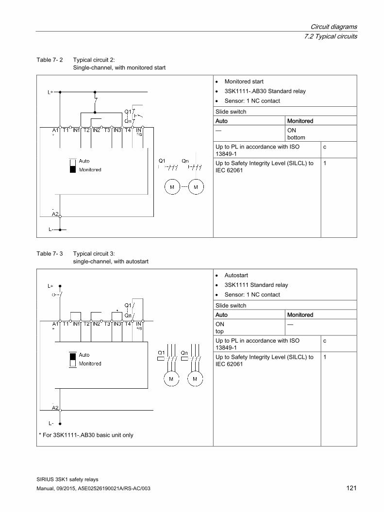
Circuit diagrams 7.2 Typical circuits
SIRIUS 3SK1 safety relays Manual, 09/2015, A5E02526190021A/RS-AC/003 121
Table 7- 2 Typical circuit 2: Single-channel, with monitored start
• Monitored start • 3SK1111-.AB30 Standard relay • Sensor: 1 NC contact
Slide switch Auto Monitored — ON
bottom Up to PL in accordance with ISO 13849-1
c
Up to Safety Integrity Level (SILCL) to IEC 62061
1
Table 7- 3 Typical circuit 3: single-channel, with autostart
* For 3SK1111-.AB30 basic unit only
• Autostart • 3SK1111 Standard relay • Sensor: 1 NC contact
Slide switch Auto Monitored ON top
—
Up to PL in accordance with ISO 13849-1
c
Up to Safety Integrity Level (SILCL) to IEC 62061
1

Circuit diagrams 7.2 Typical circuits
SIRIUS 3SK1 safety relays 122 Manual, 09/2015, A5E02526190021A/RS-AC/003
Table 7- 4 Typical circuit 4: single-channel, with autostart
• Autostart • 3SK1111-.AB30 Standard relay • Sensor: 1 NC contact
Slide switch Auto Monitored ON top
—
Up to PL in accordance with ISO 13849-1
c
Up to Safety Integrity Level (SILCL) to IEC 62061
1
Table 7- 5 Typical circuit 5: 2-channel EMERGENCY STOP, with cross-circuit detection, with monitored start
* For 3SK1111-.AB30 basic unit only
• Monitored start • With cross-circuit detection • Sensor: 2 NC contacts • 3SK1111 Standard relay
Slide switch Auto Monitored — ON
bottom Up to PL in accordance with ISO 13849-1
e
Up to Safety Integrity Level (SILCL) to IEC 62061
3
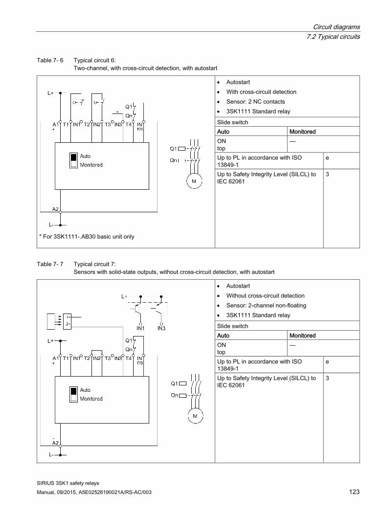
Circuit diagrams 7.2 Typical circuits
SIRIUS 3SK1 safety relays Manual, 09/2015, A5E02526190021A/RS-AC/003 123
Table 7- 6 Typical circuit 6: Two-channel, with cross-circuit detection, with autostart
* For 3SK1111-.AB30 basic unit only
• Autostart • With cross-circuit detection • Sensor: 2 NC contacts • 3SK1111 Standard relay
Slide switch Auto Monitored ON top
—
Up to PL in accordance with ISO 13849-1
e
Up to Safety Integrity Level (SILCL) to IEC 62061
3
Table 7- 7 Typical circuit 7: Sensors with solid-state outputs, without cross-circuit detection, with autostart
• Autostart • Without cross-circuit detection • Sensor: 2-channel non-floating • 3SK1111 Standard relay
Slide switch Auto Monitored ON top
—
Up to PL in accordance with ISO 13849-1
e
Up to Safety Integrity Level (SILCL) to IEC 62061
3

Circuit diagrams 7.2 Typical circuits
SIRIUS 3SK1 safety relays 124 Manual, 09/2015, A5E02526190021A/RS-AC/003
Typical circuits for 3SK1 Standard solid-state basic units or 3SK1 Advanced basic units
Table 7- 8 Typical circuit 8: EMERGENCY STOP two-channel, with cross-circuit detection, with monitored start
• Monitored start • With cross-circuit detection • 1 x two-channel • Sensor: 2 NC contacts • 3SK1112 Standard solid-state and
3SK112/3SK122 Advanced
DIP switch 1 2 3 4 ON right
ON right
ON right
—
Up to PL in accordance with ISO 13849-1
e
Up to Safety Integrity Level (SILCL) to IEC 62061
3
Table 7- 9 Typical circuit 9: Two-channel, with cross-circuit detection, with autostart
• Autostart • With cross-circuit detection • 1 x two-channel • Sensor: 2 NC contacts • 3SK1112 Standard solid-state and
3SK112/3SK122 Advanced
DIP switch 1 2 3 4 OFF left
ON right
ON right
—
Up to PL in accordance with ISO 13849-1
e
Up to Safety Integrity Level (SILCL) to IEC 62061
3

Circuit diagrams 7.2 Typical circuits
SIRIUS 3SK1 safety relays Manual, 09/2015, A5E02526190021A/RS-AC/003 125
Table 7- 10 Typical circuit 10: Electronic sensor, 2-channel, without cross-circuit detection, with monitored start
• Monitored start • Without cross-circuit detection • 1 x two-channel • Sensor: 2-channel non-floating • 3SK1112 Standard solid-state and
3SK112/3SK122 Advanced
DIP switch 1 2 3 4 ON right
OFF left
ON right
—
Up to PL in accordance with ISO 13849-1
e
Up to Safety Integrity Level (SILCL) to IEC 62061
3
Table 7- 11 Typical circuit 11: Electronic sensor, two-channel, without cross-circuit detection, with autostart
• Autostart • Without cross-circuit detection • 1 x two-channel • Sensor: 2-channel non-floating • 3SK1112 Standard solid-state and
3SK112/3SK122 Advanced
DIP switch 1 2 3 4 OFF left
OFF left
ON right
—
Up to PL in accordance with ISO 13849-1
e
Up to Safety Integrity Level (SILCL) to IEC 62061
3
Note Single-channel connection
If only one single-channel sensor is used, the other sensor circuit must be jumpered.

Circuit diagrams 7.2 Typical circuits
SIRIUS 3SK1 safety relays 126 Manual, 09/2015, A5E02526190021A/RS-AC/003
Table 7- 12 Typical circuit 12: 2 x single-channel, without cross-circuit detection, with monitored start
• Monitored start • Without cross-circuit detection • 2 x single-channel • Sensor: two single-channel NC sensors • 3SK1112 Standard solid-state and
3SK112/3SK122 Advanced
DIP switch 1 2 3 4 ON right
OFF left
OFF left
—
Up to PL in accordance with ISO 13849-1
c
Up to Safety Integrity Level (SILCL) to IEC 62061
1
Table 7- 13 Typical circuit 13: 2x single-channel, without cross-circuit detection, with autostart
• Autostart • Without cross-circuit detection • 2 x single-channel • Sensor: two single-channel NC contacts • 3SK1112 Standard solid-state and
3SK112/3SK122 Advanced
DIP switch 1 2 3 4 OFF left
OFF left
OFF left
—
Up to PL in accordance with ISO 13849-1
c
Up to Safety Integrity Level (SILCL) to IEC 62061
1

Circuit diagrams 7.2 Typical circuits
SIRIUS 3SK1 safety relays Manual, 09/2015, A5E02526190021A/RS-AC/003 127
Typical circuits for 3SK1 Advanced basic units only
Table 7- 14 Typical circuit 14: 1NC/1NO sensor, with cross-circuit detection, with monitored start
• Monitored start • With cross-circuit detection • 1 x two-channel • Jumper T1/PAR for NC/NO evaluation • Sensor: NC/NO sensor • 3SK112/3SK122 Advanced
DIP switch 1 2 3 4 ON right
ON right
ON right
—
Up to PL in accordance with ISO 13849-1
e
Up to Safety Integrity Level (SILCL) to IEC 61508
3
Table 7- 15 Typical circuit 15: 1NC/1NO sensor, with cross-circuit detection, with autostart
• Autostart • With cross-circuit detection • 1 x two-channel • Jumper T1/PAR for NC/NO evaluation • Sensor: NC/NO sensor • 3SK112/3SK122 Advanced
DIP switch 1 2 3 4 OFF left
ON right
ON right
—
PL in accordance with ISO 13849-1 e Safety Integrity Level (SILCL) to IEC 61508
3

Circuit diagrams 7.2 Typical circuits
SIRIUS 3SK1 safety relays 128 Manual, 09/2015, A5E02526190021A/RS-AC/003
Table 7- 16 Typical circuit 16: Two-hand operation with cross-circuit detection, with autostart
• Autostart • With cross-circuit detection • 2 x single-channel • Jumper T1/PAR for NC/NO evaluation • Sensor: Two-hand NO/NO sensor • 3SK112/3SK122 Advanced
DIP switch 1 2 3 4 OFF left
ON right
OFF left
—
PL in accordance with ISO 13849-1 e Safety Integrity Level (SILCL) to IEC 61508
3
You can find further information on two-hand operation in Section Two-hand operation/synchronism (Page 38).

Circuit diagrams 7.3 Typical circuits of 3SK1 safety relays with 3RM1 Failsafe motor starters
SIRIUS 3SK1 safety relays Manual, 09/2015, A5E02526190021A/RS-AC/003 129
7.3 Typical circuits of 3SK1 safety relays with 3RM1 Failsafe motor starters
7.3.1 3SK1 safety relay with 3RM1 Failsafe motor starter via device connector The 3RM13 Failsafe motor starter (24 V DC variant) is connected to a 3SK112 safety relay via a 3ZY12 device connector.
The two directions of rotation are switched on and off operationally via IN1 and IN2, e.g. with a PLC.
The control supply voltage (L+ and L-) to the motor starters is deactivated by the 3SK112 safety relay and the system is in a safe state.
Note SILCL 3 in accordance with EN 62061/PL e in accordance with EN ISO 13849-1
A safety-related application up to SILCL 3 to EN 62061:2005, PL e/Cat. 4 to EN ISO 13849-1 can be realized in this way.
To achieve SILCL 3/PL e/Cat. 4 for the safety-related application, all components of the safety functions (detecting/evaluating/reacting) must be designed accordingly.
WARNING
Bypassing the safety function when using device connectors
When operating with a 3SK112 safety relay and a device connector, the supply voltage for 3RM1 Failsafe motor starters is established via the device connectors.
To prevent bypassing of the safety function, do not connect anything to terminals A1 and A2 of the Failsafe 3RM1 motor starters in this case.

Circuit diagrams 7.3 Typical circuits of 3SK1 safety relays with 3RM1 Failsafe motor starters
SIRIUS 3SK1 safety relays 130 Manual, 09/2015, A5E02526190021A/RS-AC/003
*) If there is a common reference potential for the two inputs, it suffices to establish a ground connec-
tion. If there are separate potentials or controls, both connections must be assigned.

Circuit diagrams 7.3 Typical circuits of 3SK1 safety relays with 3RM1 Failsafe motor starters
SIRIUS 3SK1 safety relays Manual, 09/2015, A5E02526190021A/RS-AC/003 131
7.3.2 3SK1 safety relay wired with 3RM1 Failsafe motor starter The 3RM13 Failsafe motor starter (230 V supply voltage) is connected to a 3SK1 safety relay.
The two directions of rotation are switched on and off operationally via IN1 and IN2, e.g. with separate switches.
WARNING
Bypassing the safety function in the event of a fault in the case of 3RM11/3RM13 Failsafe motor starters with 110 to 230 V AC/110 V DC control supply voltage
The control signal for the control inputs in the case of 3RM11/3RM13 Failsafe motor starters with 110 to 230 V AC control supply voltage must come from A1. Otherwise, the safety function is bypassed in the event of a fault. Thus, only relay outputs are admissible when using a PLC.
Do not use a separate control voltage. Only use the relay outputs when using a PLC.
The control supply voltage (L1 and N) to the motor starters is deactivated by the 3SK1 safety relay and the system is in a safe state.
Note SILCL 3 in accordance with EN 62061, PL e/Cat. 4 in accordance with EN ISO 13849-1
A safety-related application up to SILCL 3 to EN 62061, PL e/Cat. 4 to EN ISO 13849-1 can be realized in this way.
To achieve SILCL 3/PL e/Cat. 4 for the safety-related application, all components of the safety functions (detecting/evaluating/reacting) must be designed accordingly.
Note
A fuse must be fitted as short-circuit protection (4 A gL/gG) in the supply line to the supply voltage of 3RM1 (L1).

Circuit diagrams 7.3 Typical circuits of 3SK1 safety relays with 3RM1 Failsafe motor starters
SIRIUS 3SK1 safety relays 132 Manual, 09/2015, A5E02526190021A/RS-AC/003
Figure 7-1 3SK1 safety relay with 3RM13 reversing starter

Circuit diagrams 7.4 Additional applications
SIRIUS 3SK1 safety relays Manual, 09/2015, A5E02526190021A/RS-AC/003 133
7.4 Additional applications You can find additional applications in the SIRIUS Safety Integrated application manual on the internet (https://support.industry.siemens.com/cs/document/83150405?lc=en-WW).

Circuit diagrams 7.4 Additional applications
SIRIUS 3SK1 safety relays 134 Manual, 09/2015, A5E02526190021A/RS-AC/003

SIRIUS 3SK1 safety relays Manual, 09/2015, A5E02526190021A/RS-AC/003 135
Mounting 8 8.1 Warning notices
Warning notices before installation, wiring, and commissioning
WARNING
Hazardous voltage! Can cause electric shock and burns. Turn off and lock out all power supplying this device before working on this device.

Mounting 8.2 Terminal coding
SIRIUS 3SK1 safety relays 136 Manual, 09/2015, A5E02526190021A/RS-AC/003
8.2 Terminal coding You can provide the terminals with coding pins (3ZY1440-1AA00). This helps you to avoid errors when replacing the terminals.
Figure 8-1 Module with coding pins
Figure 8-2 Stud position rotated by 60° in each case

Mounting 8.3 Mounting the devices on a level surface
SIRIUS 3SK1 safety relays Manual, 09/2015, A5E02526190021A/RS-AC/003 137
8.3 Mounting the devices on a level surface
Requirements Please note the following requirements for mounting on a level surface:
● Please observe the information about the mounting position in the chapter "General technical data (Page 204)".
● Two properly executed drill holes with thread or plug on the level surface.
For details of the distances between the drilled holes, please refer to the relevant dimension drawings in the chapter "Dimension drawings for 3SK1 devices (Page 209)".
● Two screws (17.5 mm or 22.5 mm devices)/or four screws (90 mm devices) to fit the holes M4 x 12 in accordance with DIN 784.
● Two plastic push-in lugs.
Refer to the accessories list for the relevant article number in the chapter "Accessories (Page 223)".

Mounting 8.3 Mounting the devices on a level surface
SIRIUS 3SK1 safety relays 138 Manual, 09/2015, A5E02526190021A/RS-AC/003
Procedure
Step Instructions Figure 1 Insert the push-in lugs into the open-
ings provided on the device until they engage.
17.5 mm and 22.5 mm devices
90 mm device
2 Hold the device up to the surface prepared for screw fastening.
3 Insert the screws through the elongat-ed holes into the push-in lugs.
4 Screw the device onto the level sur-face so that it is secure. Tightening torque: 1 Nm

Mounting 8.4 Disassembling devices from a level surface
SIRIUS 3SK1 safety relays Manual, 09/2015, A5E02526190021A/RS-AC/003 139
8.4 Disassembling devices from a level surface
WARNING
Hazardous Voltage
Can Cause Death, Serious Injury, or Property Damage.
Before starting work, therefore, disconnect the system and devices from the power supply.
Requirements ● The terminals have been removed or disconnected.
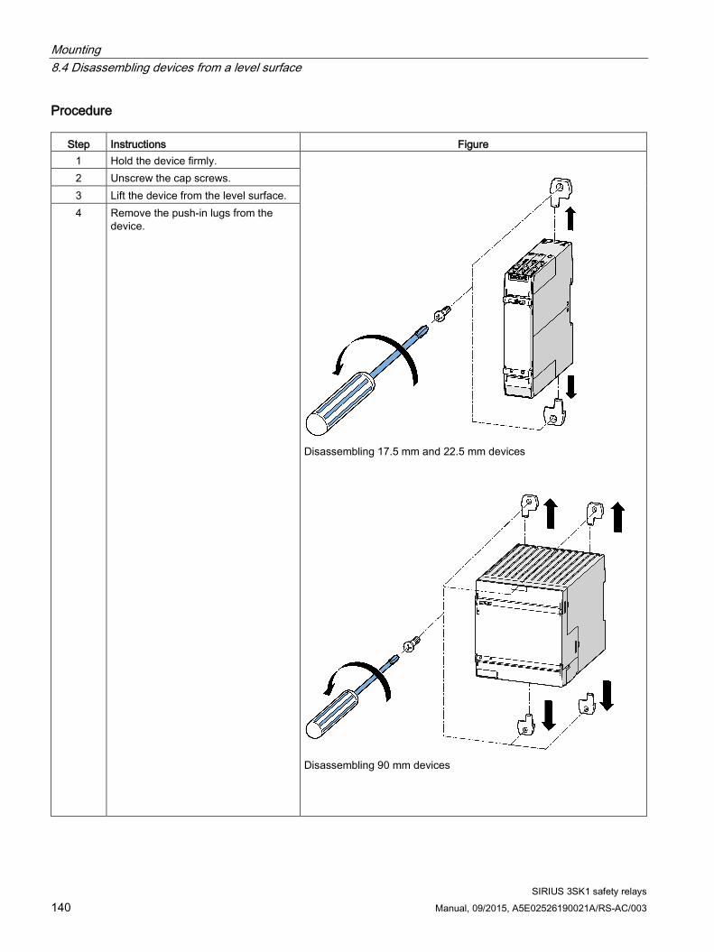
Mounting 8.4 Disassembling devices from a level surface
SIRIUS 3SK1 safety relays 140 Manual, 09/2015, A5E02526190021A/RS-AC/003
Procedure
Step Instructions Figure 1 Hold the device firmly.
Disassembling 17.5 mm and 22.5 mm devices
Disassembling 90 mm devices
2 Unscrew the cap screws. 3 Lift the device from the level surface. 4 Remove the push-in lugs from the
device.

Mounting 8.5 Mounting 22.5 mm/17.5 mm devices on a standard mounting rail
SIRIUS 3SK1 safety relays Manual, 09/2015, A5E02526190021A/RS-AC/003 141
8.5 Mounting 22.5 mm/17.5 mm devices on a standard mounting rail
Requirements ● A horizontal 35-mm wide mounting rail in accordance with DIN EN 60715 has been
properly secured at the installation location.
● Please observe the information about the mounting position in the chapter "General technical data (Page 204)".
Procedure The figures show 22.5 mm devices. The 17.5 mm devices are mounted correspondingly.
Step Instructions Figure
1 Place the back of the device onto the upper edge of the standard mounting rail.
2 Press the lower half of the device against the DIN rail until the device engages.

Mounting 8.6 Mounting the 90 mm devices on a standard mounting rail
SIRIUS 3SK1 safety relays 142 Manual, 09/2015, A5E02526190021A/RS-AC/003
8.6 Mounting the 90 mm devices on a standard mounting rail
Requirements ● A horizontal 35-mm wide mounting rail in accordance with DIN EN 60715 has been
properly secured at the installation location.
● Please observe the information about the mounting position in the chapter "General technical data (Page 204)".
Procedure
Step Instructions Figure 1 Place the back of the device onto the
upper edge of the standard mounting rail.
2 Press the lower half of the device against the DIN rail until the device engages.

Mounting 8.7 Removing devices from a standard mounting rail
SIRIUS 3SK1 safety relays Manual, 09/2015, A5E02526190021A/RS-AC/003 143
8.7 Removing devices from a standard mounting rail
WARNING
Hazardous Voltage Can Cause Death, Serious Injury, or Property Damage.
Before starting work, therefore, disconnect the system and devices from the power supply.
Requirements ● The terminals have been removed or disconnected.
Procedure
Step Instructions Figure 1 Press the device downwards.
2 Pull the lower half of the device away from the standard mounting rail.
3 Lift the device from the upper edge of the standard mounting rail.

Mounting 8.8 Mounting 22.5 mm/17.5 mm devices with device connectors on a standard mounting rail
SIRIUS 3SK1 safety relays 144 Manual, 09/2015, A5E02526190021A/RS-AC/003
8.8 Mounting 22.5 mm/17.5 mm devices with device connectors on a standard mounting rail
Requirements ● A horizontal 35-mm wide mounting rail in accordance with DIN EN 60715 has been
properly secured at the installation location.
● Please observe the information about the mounting position in the chapter "General technical data (Page 204)".
● Device connectors: Refer to the accessories list for the relevant article number in the chapter "Accessories (Page 223)".
Procedure The figures show 22.5 mm devices. The 17.5 mm devices are mounted correspondingly.
Step Instructions Figure
1 Place the back of the device connector on the upper edge of the standard mounting rail.
2 Press the lower half of the device connector against the standard mounting rail until the connector engages.
3 Repeat the procedure with all the required device connectors.

Mounting 8.8 Mounting 22.5 mm/17.5 mm devices with device connectors on a standard mounting rail
SIRIUS 3SK1 safety relays Manual, 09/2015, A5E02526190021A/RS-AC/003 145
Step Instructions Figure 4 Push the device connectors together until
they engage.
5 Mount the cover on the left of the first device connector. The cover is included in the scope of supply of the device terminator.
6 (not applica-
ble when mounting
3RM1 Fail-safe motor starters)
Set the slide switch in the device termination connector for the 3SK1 safety relay to the following positions: • below 3SK1 basic device
position 2 (bottom; i.e. open) • Below 3SK1211 output expansion
position 1 (top; i.e. closed)

Mounting 8.8 Mounting 22.5 mm/17.5 mm devices with device connectors on a standard mounting rail
SIRIUS 3SK1 safety relays 146 Manual, 09/2015, A5E02526190021A/RS-AC/003
Step Instructions Figure 7 Mount the device on the device connector.
8 Mount all the devices required for the sys-tem configuration in accordance with the respective installation guidelines on the device connectors.

Mounting 8.9 Removing 22.5 mm/17.5 mm devices with device connectors from a standard mounting rail
SIRIUS 3SK1 safety relays Manual, 09/2015, A5E02526190021A/RS-AC/003 147
8.9 Removing 22.5 mm/17.5 mm devices with device connectors from a standard mounting rail
WARNING
Hazardous Voltage Can Cause Death, Serious Injury, or Property Damage.
Before starting work, therefore, disconnect the system and devices from the power supply.
Requirements ● The terminals have been removed or disconnected.
Procedure The figures show 22.5 mm devices. The 17.5 mm devices are removed correspondingly.
Step Instructions Figure
1 Unlock the device using a screwdriver.
2 Pull the lower half of the device away from the device connector.
3 Unlock the device using a screwdriver.

Mounting 8.9 Removing 22.5 mm/17.5 mm devices with device connectors from a standard mounting rail
SIRIUS 3SK1 safety relays 148 Manual, 09/2015, A5E02526190021A/RS-AC/003
Step Instructions Figure 4 Pull the device away from the device
connector.
5 Separate the device connectors using
a screwdriver.
6 Remove the cover.

Mounting 8.9 Removing 22.5 mm/17.5 mm devices with device connectors from a standard mounting rail
SIRIUS 3SK1 safety relays Manual, 09/2015, A5E02526190021A/RS-AC/003 149
Step Instructions Figure 7 Press the device connector down.
8 Pull the lower half of the device con-nector away from the standard mount-ing rail.
9 Lift the device connector from the upper edge of the standard mounting rail.

Mounting 8.10 Mounting 90 mm devices with device connectors on a standard mounting rail
SIRIUS 3SK1 safety relays 150 Manual, 09/2015, A5E02526190021A/RS-AC/003
8.10 Mounting 90 mm devices with device connectors on a standard mounting rail
Requirements ● A horizontal 35-mm wide mounting rail in accordance with DIN EN 60715 has been
properly secured at the installation location.
● Please observe the information about the mounting position in the chapter "General technical data (Page 204)".
● Use the device termination connector set for 3SK1 safety relays, > 45 mm wide. Refer to the accessories list for the relevant article number in the chapter "Accessories (Page 223)".
● Please observe the obligatory mounting rules in Section: "System configuration rules (Page 107)".
Procedure
Step Instructions Figure 1 Hang the back of the device connector
onto the upper edge of the standard mounting rail.
2 Press the lower half of the device connector against the standard mount-ing rail until the connector engages.
3 Repeat the procedure with all the required device connectors.

Mounting 8.10 Mounting 90 mm devices with device connectors on a standard mounting rail
SIRIUS 3SK1 safety relays Manual, 09/2015, A5E02526190021A/RS-AC/003 151
Step Instructions Figure 4 Push the device connectors together
until they engage.
5 Mount the cover on the left of the first device connector piece and the device connectors supplied in the set for enclosures of 45 mm upwards (right-hand side).
6 Note the clearances required for the 90 mm devices.

Mounting 8.10 Mounting 90 mm devices with device connectors on a standard mounting rail
SIRIUS 3SK1 safety relays 152 Manual, 09/2015, A5E02526190021A/RS-AC/003
Step Instructions Figure 7 Mount the 3SK1213 output expansion
on the device connectors.
8 Mount all the devices required for the system configuration in accordance with the respective installation guide-lines on the device connectors.
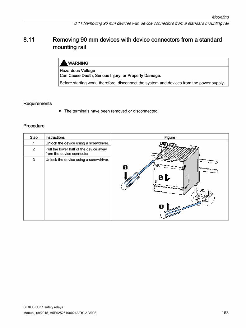
Mounting 8.11 Removing 90 mm devices with device connectors from a standard mounting rail
SIRIUS 3SK1 safety relays Manual, 09/2015, A5E02526190021A/RS-AC/003 153
8.11 Removing 90 mm devices with device connectors from a standard mounting rail
WARNING
Hazardous Voltage Can Cause Death, Serious Injury, or Property Damage.
Before starting work, therefore, disconnect the system and devices from the power supply.
Requirements ● The terminals have been removed or disconnected.
Procedure
Step Instructions Figure 1 Unlock the device using a screwdriver.
2 Pull the lower half of the device away from the device connector.
3 Unlock the device using a screwdriver.

Mounting 8.11 Removing 90 mm devices with device connectors from a standard mounting rail
SIRIUS 3SK1 safety relays 154 Manual, 09/2015, A5E02526190021A/RS-AC/003
Step Instructions Figure 4 Pull the device away from the device
connector.
5 Separate the device connectors using
a screwdriver.
6 Disassemble the terminating section.

Mounting 8.11 Removing 90 mm devices with device connectors from a standard mounting rail
SIRIUS 3SK1 safety relays Manual, 09/2015, A5E02526190021A/RS-AC/003 155
Step Instructions Figure 7 Press the device connector down.
8 Pull the lower half of the device con-nector away from the standard mount-ing rail.
9 Lift the device connector from the upper edge of the standard mounting rail.

Mounting 8.12 Mounting 22.5 mm/17.5 mm devices with device connectors on the wall
SIRIUS 3SK1 safety relays 156 Manual, 09/2015, A5E02526190021A/RS-AC/003
8.12 Mounting 22.5 mm/17.5 mm devices with device connectors on the wall
Requirements Please note the following requirements for mounting on a level surface:
● Please observe the information about the mounting position in the chapter "General technical data (Page 204)".
● Two properly executed drill holes (per device connector) with thread or plug on the level surface.
For details of the distances between the drilled holes, please refer to the relevant dimension drawings in the chapter "Dimension drawings 3SK1 device connectors".
● Two screws (per device connector) to fit the holes M4 x12 in accordance with DIN 784.
● Device connector
Refer to the accessories list for the relevant article number in the chapter "Accessories (Page 223)".

Mounting 8.12 Mounting 22.5 mm/17.5 mm devices with device connectors on the wall
SIRIUS 3SK1 safety relays Manual, 09/2015, A5E02526190021A/RS-AC/003 157
Procedure for mounting on a level surface The figures show 22.5 mm devices. The 17.5 mm devices are mounted correspondingly.
Step Instructions Figure
1 Push the device connectors together until they engage.
2 Mount the cover on the left of the first device connector. The cover is included in the scope of supply of the device terminator.
3 (not applicable when mounting 3RM1 Failsafe motor starters)
Set the slide switch in the device termination connector for the 3SK1 safety relays to the following positions: • below 3SK1 basic device
position 2 (bottom; i.e. open) • below 3SK1211 output expansion
position 1 (top; i.e. closed)
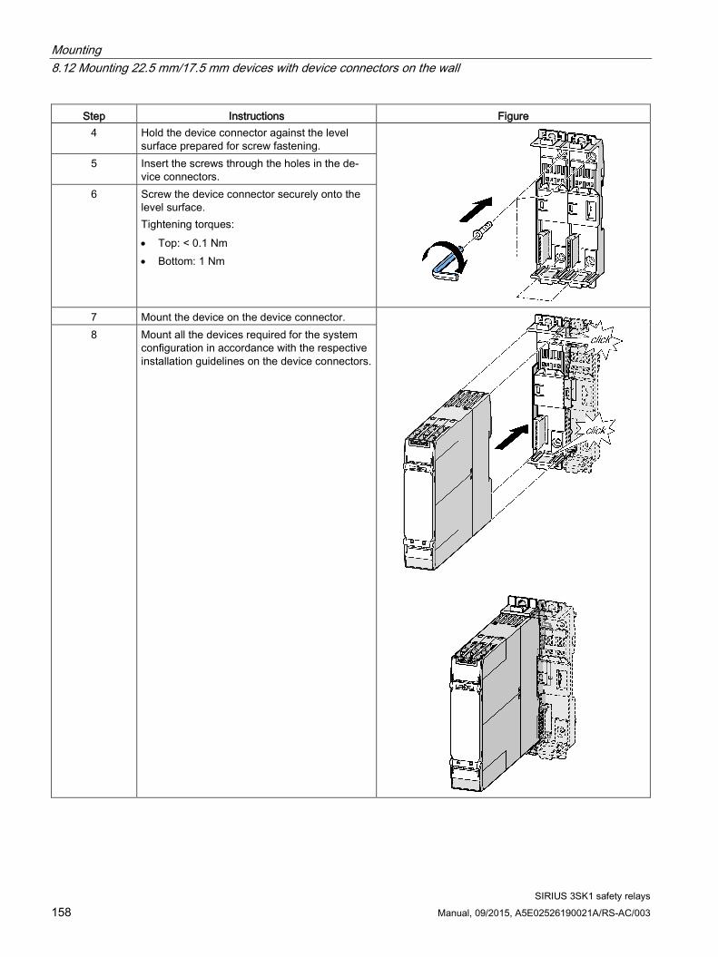
Mounting 8.12 Mounting 22.5 mm/17.5 mm devices with device connectors on the wall
SIRIUS 3SK1 safety relays 158 Manual, 09/2015, A5E02526190021A/RS-AC/003
Step Instructions Figure 4 Hold the device connector against the level
surface prepared for screw fastening.
5 Insert the screws through the holes in the de-vice connectors.
6 Screw the device connector securely onto the level surface. Tightening torques: • Top: < 0.1 Nm • Bottom: 1 Nm
7 Mount the device on the device connector.
8 Mount all the devices required for the system configuration in accordance with the respective installation guidelines on the device connectors.

Mounting 8.13 Removing 22.5 mm/17.5 mm devices with device connectors from the wall
SIRIUS 3SK1 safety relays Manual, 09/2015, A5E02526190021A/RS-AC/003 159
8.13 Removing 22.5 mm/17.5 mm devices with device connectors from the wall
WARNING
Hazardous Voltage Can Cause Death, Serious Injury, or Property Damage.
Before starting work, therefore, disconnect the system and devices from the power supply.
Requirements ● The terminals have been removed or disconnected.
Procedure The figures show 22.5 mm devices. The 17.5 mm devices are removed correspondingly.
Step Instructions Figure
1 Unlock the device (below) using a screwdriver.
2 Pull the lower half of the device away from the device connector.
3 Unlock the device (above) using a screwdriver.

Mounting 8.13 Removing 22.5 mm/17.5 mm devices with device connectors from the wall
SIRIUS 3SK1 safety relays 160 Manual, 09/2015, A5E02526190021A/RS-AC/003
Step Instructions Figure 4 Pull the device away from the device
connector.
5 Release the screws.
6 Separate the device connectors.
7 Remove the cover.

Mounting 8.14 Mounting 90 mm devices with device connectors on the wall
SIRIUS 3SK1 safety relays Manual, 09/2015, A5E02526190021A/RS-AC/003 161
8.14 Mounting 90 mm devices with device connectors on the wall
Requirements Please note the following requirements for mounting on a level surface:
● Please observe the information about the mounting position in the chapter "General technical data (Page 204)".
● Two properly executed drill holes with thread or plug on the level surface (per device connector).
● Two M4 x 12 screws in accordance with DIN 784 (per device connector) to fit the holes.
● Use the device termination connector set for 3SK1 safety relays, > 45 mm wide. Refer to the accessories list for the relevant article number in the chapter "Accessories (Page 223)".
Procedure
Step Instructions Figure 1 Push the device connectors together
until they engage.
2 Mount the cover on the left of the first device connector.

Mounting 8.14 Mounting 90 mm devices with device connectors on the wall
SIRIUS 3SK1 safety relays 162 Manual, 09/2015, A5E02526190021A/RS-AC/003
Step Instructions Figure 3 Note the clearances required for the
90 mm devices. Mount the device connector supplied in the set for enclosures of 45 mm upwards (right-hand side). Tightening torques: • Top: < 0.1 Nm • Bottom: 1 Nm
4 Hold the device connector against the
level surface prepared for screw fas-tening.
5 Insert the screws through the holes in the device connectors.
6 Screw the device connector securely onto the level surface.

Mounting 8.14 Mounting 90 mm devices with device connectors on the wall
SIRIUS 3SK1 safety relays Manual, 09/2015, A5E02526190021A/RS-AC/003 163
Step Instructions Figure 7 Mount the 3SK1213 output expansion
on the device connectors
8 Mount all the devices required for the system configuration in accordance with the respective installation guide-lines on the device connectors.

Mounting 8.15 Removing 90 mm devices with device connectors from wall
SIRIUS 3SK1 safety relays 164 Manual, 09/2015, A5E02526190021A/RS-AC/003
8.15 Removing 90 mm devices with device connectors from wall
WARNING
Hazardous Voltage Can Cause Death, Serious Injury, or Property Damage.
Before starting work, therefore, disconnect the system and devices from the power supply.
Requirements ● The terminals have been removed or disconnected.
Procedure
Step Instructions Figure 1 Unlock the device (bottom) using a
screwdriver.
2 Pull the lower half of the device away from the device connector.
3 Unlock the device (top) using a screwdriver.

Mounting 8.15 Removing 90 mm devices with device connectors from wall
SIRIUS 3SK1 safety relays Manual, 09/2015, A5E02526190021A/RS-AC/003 165
Step Instructions Figure 4 Pull the device away from the device
connector.
5 Release the screws.
6 Separate the device connectors.
7 Remove the cover.

Mounting 8.16 Mounting the sealable cover
SIRIUS 3SK1 safety relays 166 Manual, 09/2015, A5E02526190021A/RS-AC/003
8.16 Mounting the sealable cover The sealable cover (3ZY1321-1AA00 for 17.5 mm devices, 3ZY1321-2AA00 for 22.5 mm devices) can be used to secure the DIP switches (and, if present, the potentiometers for setting the delay time) of the safety relays against unauthorized or unintended readjustment.
As an alternative, Siemens also offers a sealable membrane (3TK2820-0AA00) for securing the safety relays. The sealable membrane is fixed to the front of the safety relay and secures the DIP switches and the buttons (and potentiometers) against unintentional readjustment.
Mounting the sealable cover
Step Instructions Figure 1 Attach the hooks on the cover
to the openings on the device and fold the cover up.
2 Seal the cover to secure it against unauthorized removal. Sealing wire diameter, max.: 2 mm

SIRIUS 3SK1 safety relays Manual, 09/2015, A5E02526190021A/RS-AC/003 167
Connection 9 9.1 22.5 mm/17.5 mm devices
9.1.1 Terminal assignment
Location of the connections The inside faces of the terminal covers are labeled with the designations of the relevant terminals. The position of the label corresponds to the position of the respective terminal.
Figure 9-1 Upper terminal cover

Connection 9.1 22.5 mm/17.5 mm devices
SIRIUS 3SK1 safety relays 168 Manual, 09/2015, A5E02526190021A/RS-AC/003
Figure 9-2 Lower terminal cover
9.1.2 Connection data for terminals
Specification and value in the case of removable terminals with screw-type terminals
Screwdriver
Cross-tip screwdriver Size: PZ 1x80 (⌀ 4.5 mm) Torque: 0.6 to 0.8 Nm
Rigid cable
A = 10 mm 1 x 0.5 ... 2.5 mm² 2 x 1.0 ... 1.5 mm²
Flexible conductor with end sleeve
A = 10 mm 1 x 0.5 ... 2.5 mm² 2 x 0.5 ... 1.0 mm²
Flexible cable
Not permissible
AWG 1 x 20 to 14 2 x 18 to 16

Connection 9.1 22.5 mm/17.5 mm devices
SIRIUS 3SK1 safety relays Manual, 09/2015, A5E02526190021A/RS-AC/003 169
9.1.3 Connecting the screw-type terminals
WARNING
Hazardous Voltage Can Cause Death, Serious Injury, or Property Damage.
Before starting work, therefore, disconnect the system and devices from the power supply.
Requirements ● Cross-tip screwdriver size PZ 1 x 80.
● For suitable connection cross-sections of the cables, see the chapter "Connection data for terminals (Page 168)".
Procedure
Step Instructions Figure 1 Insert the relevant cable into square on the
screw-type terminal until it engages.
2 Hold the cable in the screw-type terminal. 3 Tighten the screw with a torque of 0.6 ... 0.8
Nm. 4 Pull on the cable to ensure it is screwed tight.

Connection 9.1 22.5 mm/17.5 mm devices
SIRIUS 3SK1 safety relays 170 Manual, 09/2015, A5E02526190021A/RS-AC/003
9.1.4 Disconnecting the screw-type terminals
WARNING
Hazardous Voltage Can Cause Death, Serious Injury, or Property Damage.
Before starting work, therefore, disconnect the system and devices from the power supply.
Requirements ● Cross-tip screwdriver size PZ 1 x 80
Procedure
Step Instructions Figure 1 Unscrew the screw of the screw-type terminal.
2 Remove the cable from the unscrewed screw-type terminal.

Connection 9.1 22.5 mm/17.5 mm devices
SIRIUS 3SK1 safety relays Manual, 09/2015, A5E02526190021A/RS-AC/003 171
9.1.5 Wiring rules for spring-loaded terminals (with push-in technology) Wiring rules for ... Control current terminals Connectable cross-sections for solid cables 2 x 0.5 ... 2 x 1.5 mm²
(AWG1): 20 ... 16) Connectable cross-sections for flexible cables
Without end sleeve 2 x 0.5 ... 2 x 1.5 mm² (AWG1): 20 ... 16)
With end sleeve (with and without plastic sleeve)
2 x 0.5 ... 2 x 1.0 mm² 2) (AWG1): 20 ... 18)
With TWIN end sleeve --- ---
Cable stripping length 10 ... 11 mm End sleeves according to DIN 46228-4 with plastic sleeve 10 mm 1) AWG: American Wire Gauge (AWG does not define use of end sleeves)
2) When 2 x 1.0 mm² end sleeves with a plastic sleeve are used, space problems may arise with the sleeves; as an alter-native, you are advised to use end sleeves without plastic sleeves
Notes on handling spring-loaded terminals with push-in technology The terminal area of the spring-loaded terminals is rectangular, and the maximum overall dimensions of the conductor to be wired must not exceed 1.5 x 2.4 mm (control current terminals).
Attention must be paid to the orientation of the terminal area, which may call for vertical fitting of rectangularly crimped cables. To make optimum use of available terminal area, you are advised to choose a form of crimping that creates a corresponding rectangular contour. Trapezoidal crimping is generally very highly suitable in this case.
When use is made of a cable that utilizes the full overall height, the terminal's spring is deflected to the maximum. Therefore, removal of this cable may become a problem because it requires further deflection of the spring. Control current terminals
Terminal area of control current terminals

Connection 9.1 22.5 mm/17.5 mm devices
SIRIUS 3SK1 safety relays 172 Manual, 09/2015, A5E02526190021A/RS-AC/003
9.1.6 Connecting the push-in terminals
WARNING
Hazardous Voltage Can Cause Death, Serious Injury, or Property Damage.
Before starting work, therefore, disconnect the system and devices from the power supply.
Push-in connections are a form of spring-loaded terminals allowing wiring without tools for rigid conductors or conductors equipped with end sleeves.
For wiring finely-stranded or stranded conductors without end sleeves on push-in connections, a screwdriver is required.
Requirements ● 0.5 x 3 mm screwdriver DIN 5264 (for finely-stranded conductors only).
● For suitable connection cross-sections of the cables, see the chapter "Connection data for terminals (Page 168)".
Procedure
Table 9- 1 Rigid conductors or conductors equipped with end sleeves
Step Instructions Figure 1 Insert the cable into the oval opening as far as
it will go.
2 Pull on the cable to ensure it is tight.

Connection 9.1 22.5 mm/17.5 mm devices
SIRIUS 3SK1 safety relays Manual, 09/2015, A5E02526190021A/RS-AC/003 173
Table 9- 2 Finely-stranded conductors
Step Instructions Figure 1 Insert the screwdriver in the rectangular open-
ing to open the terminal (oval opening).
2 Insert the cable as far as it will go into the oval opening and remove the screwdriver.
3 Pull on the cable to ensure it is tight.

Connection 9.1 22.5 mm/17.5 mm devices
SIRIUS 3SK1 safety relays 174 Manual, 09/2015, A5E02526190021A/RS-AC/003
9.1.7 Disconnecting the push-in terminals
WARNING
Hazardous Voltage Can Cause Death, Serious Injury, or Property Damage.
Before starting work, therefore, disconnect the system and devices from the power supply.
Requirements ● Screwdriver DIN 5264 of the size 0.5 x 3 mm
Procedure
Step Instructions Figure 1 Insert the screwdriver into the rectangular
opening of the spring-loaded terminal until it engages.
2 Remove the cable from the oval opening. 3 Remove the screwdriver.

Connection 9.1 22.5 mm/17.5 mm devices
SIRIUS 3SK1 safety relays Manual, 09/2015, A5E02526190021A/RS-AC/003 175
9.1.8 Attaching the terminals
WARNING
Hazardous voltage
Can Cause Death, Serious Injury, or Property Damage.
Before starting work, therefore, disconnect the system and devices from the power supply.
Requirements You must have removed the terminals, for the purpose of replacing a device, for example.
Procedure when plugging in the terminals Step Instructions Figure
1 Insert the detachable terminals into the guide rail of the device.
2 Slide the detachable terminals back until they audibly engage.

Connection 9.1 22.5 mm/17.5 mm devices
SIRIUS 3SK1 safety relays 176 Manual, 09/2015, A5E02526190021A/RS-AC/003
9.1.9 Disconnecting
WARNING
Hazardous Voltage
Can Cause Death, Serious Injury, or Property Damage.
Before starting work, therefore, disconnect the system and devices from the power supply.
Removing terminals from the device
Step Instructions Figure 1 Press the clip of the terminals upwards.
2 Pull the terminals out to the front. 3 Lift the terminals out of the guide rail of the
device.

Connection 9.1 22.5 mm/17.5 mm devices
SIRIUS 3SK1 safety relays Manual, 09/2015, A5E02526190021A/RS-AC/003 177
Screw terminals: Disconnecting the conductor
Step Instructions Figure 1 Unscrew the screw of the screw-type terminal.
2 Remove the cable from the unscrewed screw-type terminal.
Push-in terminals: Disconnecting the conductor
Step Instructions Figure 1 Insert the screwdriver into the rectangular
opening of the push-in terminal until it engag-es. Please observe a 10° horizontal angular deviation of the screwdriver to the oval open-ing.
2 Remove the cable from the oval opening. 3 Remove the screwdriver.

Connection 9.2 Devices 90 mm
SIRIUS 3SK1 safety relays 178 Manual, 09/2015, A5E02526190021A/RS-AC/003
9.2 Devices 90 mm
9.2.1 Opening the terminal cover
WARNING
Hazardous Voltage
Can Cause Death, Serious Injury, or Property Damage.
Before starting work, therefore, disconnect the system and devices from the power supply.
Positions of the terminals and opening the terminal cover Ther removable terminals are located under the lower terminal cover.
To open the terminal cover, press on it in the middle ① and lift it up ②.

Connection 9.2 Devices 90 mm
SIRIUS 3SK1 safety relays Manual, 09/2015, A5E02526190021A/RS-AC/003 179
9.2.2 Connection data for terminals
Screwdriver for removable terminals with screw-type terminals
Screwdriver for removable terminals with spring-loaded terminals
Screwdriver
Cross-tip screwdriver Size: PZ 1 (⌀ 4 mm) Torque: 0.8 to 1.2 Nm
Screwdriver Size: 0 or 1 (width to 3 mm) for raising the terminal springs DIN 5264-A; 0.5 x 3
Rigid cable
A = 10 mm 1 x 0.5 ... 4.0 mm2 2 x 0.5 ... 2.5 mm2
A = 10 mm 1 x 0.5 ... 1.5 mm² 2 x 0.5 ... 1.5 mm²
Flexible cable with end sleeve/cable lug
A = 10 mm 1 x 0.5 ... 2.5 mm² 2 x 0.5 ... 1.5 mm²
A = 10 mm 1 x 0.5 ... 1.5 mm² 2 x 0.5 ... 1.5 mm²
Flexible cable
Not permissible A = 10 mm 1 x 0.5 ... 1.5 mm² 2 x 0.5 ... 1.5 mm²
AWG 1 x 20 to 12 2 x 18 to 14
1 x 20 to 16 2 x 20 to 16

Connection 9.2 Devices 90 mm
SIRIUS 3SK1 safety relays 180 Manual, 09/2015, A5E02526190021A/RS-AC/003
9.2.3 Connecting terminals
WARNING
Hazardous Voltage
Can Cause Death, Serious Injury, or Property Damage.
Before starting work, therefore, disconnect the system and devices from the power supply.
Procedure for screw-type terminal blocks
Step Instructions Figure 1 Insert the relevant cable into square on the
screw-type terminal until it engages.
2 Hold the cable in the screw-type terminal. 3 Tighten the screw of the terminal in which the
cable is inserted. 4 Pull on the cable to ensure it is screwed tight.

Connection 9.2 Devices 90 mm
SIRIUS 3SK1 safety relays Manual, 09/2015, A5E02526190021A/RS-AC/003 181
Procedure for spring-loaded terminals
Step Instructions Figure 1 To release the clamping springs, insert the
screwdriver as far as it will go into the rectan-gular opening of the spring-loaded terminal. Please observe a 10° horizontal angular devia-tion of the screwdriver to the oval opening.
2 Insert the cable into the oval opening as far as it will go.
3 Hold the cable in the spring-loaded terminal. 4 Remove the screwdriver. 5 Pull on the cable to ensure it is tight.

Connection 9.2 Devices 90 mm
SIRIUS 3SK1 safety relays 182 Manual, 09/2015, A5E02526190021A/RS-AC/003
9.2.4 Mounting terminals
WARNING
Hazardous voltage
Can Cause Death, Serious Injury, or Property Damage.
Before starting work, therefore, disconnect the system and devices from the power supply.
Requirements You must have removed the terminals, for the purpose of replacing a device, for example.
Procedure for mounting terminals Step Instructions Figure
1 Insert the detachable terminals into the guide rail of the device.
2 Slide the detachable terminals back until they audibly engage.
3 Check that the clip of the removable terminals closes flush with the front panel.

Connection 9.2 Devices 90 mm
SIRIUS 3SK1 safety relays Manual, 09/2015, A5E02526190021A/RS-AC/003 183
9.2.5 Disconnecting
WARNING
Hazardous Voltage Can Cause Death, Serious Injury, or Property Damage.
Before starting work, therefore, disconnect the system and devices from the power supply.
Removing terminals from the device
Step Instructions Figure 1 Insert a flat-head screwdriver between the clip
of the terminals and the front panel.
2 Pull the terminals out to the front. 3 Lift the terminals out of the guide rail of the
device.

Connection 9.2 Devices 90 mm
SIRIUS 3SK1 safety relays 184 Manual, 09/2015, A5E02526190021A/RS-AC/003
Disconnecting screw-type terminals
Step Instructions Figure 1 Insert the screwdriver into the screw-type ter-
minal.
2 Unscrew the screw of the screw-type terminal. 3 Remove the cable from the unscrewed screw-
type terminal.
Disconnecting spring-loaded terminals
Step Instructions Figure 1 Insert the flat-head screwdriver into the rec-
tangular opening of the spring-loaded terminal until it engages. Please observe a 10° horizon-tal angular deviation of the screwdriver to the oval opening.
2 Remove the cable from the oval opening. 3 Remove the screwdriver.

Connection 9.3 Device replacement
SIRIUS 3SK1 safety relays Manual, 09/2015, A5E02526190021A/RS-AC/003 185
9.3 Device replacement
WARNING
Hazardous Voltage Can Cause Death, Serious Injury, or Property Damage.
Before starting work, therefore, disconnect the system and devices from the power supply.
When replacing a device, you do not need to re-wire it. The terminals can be disconnected from the defective device and then connected to the new device.
You can provide the terminals with coding pins. These are to help you avoid errors when replacing the terminals (see the chapter "Terminal coding (Page 136)" for more details).
Replacing the module
WARNING
Hazardous Voltage Can Cause Death, Serious Injury, or Property Damage. Carry out function test of the plant
To ensure the safety of the system, a full functional test must be conducted and a successful result obtained after a device has been replaced.
Note
Only replace a defective device with a device of an identical article number.
1. Disconnect the defective device at the terminals.
– Chapter for 22.5 mm devices Disconnecting (Page 176)
– Chapter for 90 mm devices Disconnecting (Page 183)
2. Deinstall the defective device.
– Chapter "Removing devices from a standard mounting rail (Page 143)"
– Chapter "Removing 22.5 mm/17.5 mm devices with device connectors from a standard mounting rail (Page 147)"
– Chapter "Removing 90 mm devices with device connectors from a standard mounting rail (Page 153)"

Connection 9.3 Device replacement
SIRIUS 3SK1 safety relays 186 Manual, 09/2015, A5E02526190021A/RS-AC/003
3. Mount the new device
– Chapter "Mounting the devices on a level surface (Page 137)"
– Chapter "Mounting 22.5 mm/17.5 mm devices on a standard mounting rail (Page 141)"
– Chapter "Mounting the 90 mm devices on a standard mounting rail (Page 142)"
– Chapter "Mounting 22.5 mm/17.5 mm devices with device connectors on the wall (Page 156)"
– Chapter "Mounting 90 mm devices with device connectors on the wall (Page 161)"
4. Connect the defective device at the terminals
– Chapter for 22.5 mm devices "Connecting the screw-type terminals (Page 169)", "Connecting the push-in terminals (Page 172)" and "Attaching the terminals (Page 175)"
– Chapter for 90 mm devices "Connecting terminals (Page 180)" and "Mounting terminals (Page 182)"
5. Set the DIP switches/slide switches and, if applicable, the times according to the defective device.
After applying the supply voltage, the new 3SK1 basic unit checks whether the hardware configuration matches the device configuration.
If there are no deviations, the system re-enters safety mode.

SIRIUS 3SK1 safety relays Manual, 09/2015, A5E02526190021A/RS-AC/003 187
Configuration / operation 10 10.1 Procedure for configuration
General information:
● It is only possible to change the configuration (DIP switch, NC/NO evaluation, potentiometer, input and output expansion) in configuration mode. Modifications during operation are not accepted.
● A configuration change (DIP switch, NC/NO evaluation, potentiometer) is indicated in safety mode by the "DEVICE" LED flashing green/yellow, but does not change the device function.
● In safety mode, if a change in the system configuration (input and output expansion) is detected, the device switches to error mode ("DEVICE" LED and "SF" LED red). A restart is only possible using Power OFF/ON.
Procedure for configuring a basic unit 1. Set the configuration (DIP, PAR, potentiometer, input expansion, output expansion) in
accordance with the desired function.
2. Connect the power supply.
3. If the device detects a modified configuration, it remains in configuration mode (LEDs flash) during power up.
4. Confirm the new configuration by operating the SET/RESET pushbutton for more than 1s.
5. The configuration has been accepted and the device changes to safety mode.
Note Configuration and setting the delay time
A change to the configuration must only ever be carried out when the system is disconnected from the power. In safety mode, an adjustment to the potentiometer does not result in a change to the parameterized delay time. A change to the potentiometer setting made during operation is not accepted and is indicated in safety mode by a yellow/green flashing "DEVICE" LED. The device can be restarted by performing a RESET (pressing the SET/RESET button) or by disconnecting and reconnecting the supply voltage. Following a restart, the device remains in safety configuration mode during power up (all safety-related outputs are shut down) until the new delay time is accepted by pressing the SET/RESET button.

Configuration / operation 10.2 Explanation of the device's functions
SIRIUS 3SK1 safety relays 188 Manual, 09/2015, A5E02526190021A/RS-AC/003
10.2 Explanation of the device's functions
Explanation of the device's functions (DIP switches) DIP switch
Parameter Function
1 Start type • Autostart: The safety-related outputs are switched to the active position as soon as the switch-on condition is satisfied at the sensor inputs IN1, IN2, INF and INK. The START button connection terminal INS is not queried.
• Monitored start: The safety-related outputs are switched to the active position as soon as the switch-on condition is met at the IN1, IN2, INF und INK sensor inputs and the START button at the INS terminal is actuated (start with the falling edge).
2 Cross-circuit detec-tion
Cross-circuit detection is only possible with floating sensors. The sensors must be connected between T1 - IN1 and T2 – IN2. At the terminals IN1 and PAR (if used), the test signal of terminal T1 is expected; at the terminals IN2 and INF , the test signal of T2 is expected. The device detects a sensor fault if the signal at the terminals IN1, PAR or IN2, INF does not match the test signals T1, T2. Cross-circuit detection must be deactivated if electronic sensors such as light arrays or laser scanners are connected. The 3SK1 now no longer monitors the sensor inputs for cross-circuit detection. Usually, the outputs of safety sensors (OSSD) are already mon-itored for cross-circuits in the sensor. Devices with PAR terminals expect the test signal T2 at the parameterization input. A 24 V signal at the PAR or INF terminals results in a fault (cross-circuit at the input).
3 Type of connection • 1 sensor with 2 contacts (1 x 2-channel) (NC/NC). It is expected here that both contacts be open simultaneously. With the additional connection of T1 to PAR, this DIP parameterization applies to ONE 2-channel sensor with NC/NO contacts.
• 2 sensors with one contact each (2x single-channel) (NC/NC). It is expected that both sensors are ANDed. Simultaneity is not monitored.
4 Startup testing After a power failure, startup testing requires that the sensors at IN1 and IN2 are actu-ated once by the system operator.

Configuration / operation 10.2 Explanation of the device's functions
SIRIUS 3SK1 safety relays Manual, 09/2015, A5E02526190021A/RS-AC/003 189
Function of the cascading input (INK terminal) 1. Safe combination of safety relays
In this application, a higher-level safety relay switches off the 3SK1 safety relay via the cascading input via a safe output. Example: an EMERGENCY STOP circuit is to deactivate the entire installation as a higher-level circuit. Several function groups (e.g., protective doors) that disconnect locally can be operated as subordinate units.
WARNING
Application / safety relay safety level
The safety level (PL/SIL) of the application corresponds to the lowest safety level of a subsystem of the application when errors are excluded (protected wiring of the control cable).
2. Additional safety sensor circuit The INK cascading input is ANDed with sensor inputs IN1, IN2 . PL c in accordance with ISO 13849-1, or SIL1 in accordance with IEC 62061 can be achieved if the cascading input is wired with single-channel (positive opening) safety sensors (supply via A1 / +24 V (identical potential to A1)) and if the connecting cable is laid in a protected fashion. The start function for the cascading input INK corresponds to the start response of sensor inputs IN1 and IN2 (autostart or monitored start). The cascading input INK can be triggered with floating or solid-state contact blocks (switching to P potential). Floating contact blocks must be connected between A1 / +24 V (identical potential to A1) and the cascading input.
3. Normal switching duty The INK cascading input can also be used for normal switching duty (not safe). The INK cascading input can be activated in this case with floating contact blocks or with solid-state contact blocks (switching to P potential). Floating contact blocks must be connected between A1 / +24 V and INK . It is important to note that the start function of cascading input INK corresponds to the start function of sensor inputs IN1, IN2.

Configuration / operation 10.2 Explanation of the device's functions
SIRIUS 3SK1 safety relays 190 Manual, 09/2015, A5E02526190021A/RS-AC/003
When using a 3SK1 safety relay with instantaneous and time-delayed contacts, the two following safety notes must always be observed:
NOTICE
In the event of external faults such as: • Cross-circuit fault • Short circuit to ground • Current-source short circuit
and to access the configuration mode for copying a delay time after a reset, the following device behavior must always be taken into account:
The outputs of stop category 0 switch instantaneously, while the outputs of stop category 1 have a time delay. The sequence cannot be interrupted. Exception: Switching off the power supply.
NOTICE
Saving the starting command: 1. If the safe state is restored during the time delay, (e.g. the protective door is closed) and
the START button is actuated, the safety-related outputs switch to the active position immediately after the delay time has elapsed. The actuation of the START button is saved.
2. If a sensor is actuated at an input expansion within the system configuration, the entire system is disconnected. If the START button on the basic device is then actuated while the sensor on the input expansion is actuated (for instance, if the protective door is open), the command will be saved by the basic device. This results in an automatic start of the system once the sensor at the input expansion is reset (for example, a protective door is closed again). This system response is identical in the system configuration for all 3SK1 basic units.
For additional notes/explanations on this topic, see the following FAQ (https://support.industry.siemens.com/cs/ww/en/view/103655974)
NOTICE
Observe the following in the case of protective doors with tumblers:
If the voltage Us is disconnected on devices with time-delayed outputs between switching the instantaneous outputs and the time-delayed outputs, the delay time expires when the voltage Us is restored, and the time-delayed contacts change their switch positions.

Configuration / operation 10.3 Modes
SIRIUS 3SK1 safety relays Manual, 09/2015, A5E02526190021A/RS-AC/003 191
10.3 Modes The 3SK1 safety relays have four main operating modes:
● Power-up
● Configuration mode
● Safety mode
● Error mode
Power-up On powering up (up to 7 seconds), the 3SK1 safety relay runs through a complete function test.
Configuration mode A saved configuration can only be modified in configuration mode.
The configuration must only ever be modified after disconnecting the power supply.
If the device detects a configuration change during the restart (DIP, PAR, potentiometer, input expansion, output expansion), it does not change automatically to safety mode after power up, but instead remains in configuration mode. In configuration mode, the LEDs (yellow) whose DIP switch position is ON (right) flash; all other parameter settings are not explicitly indicated.
The configuration is accepted by pressing the SET/RESET button for approximately 1s.
In configuration mode, the device is in the safe state. No monitoring functions are active.
Note
A configuration change made during operation is not accepted, and in safety mode, this is indicated by a yellow/green flashing "DEVICE" LED. The device can be restarted by performing a RESET (pressing the SET/RESET button) or by disconnecting and reconnecting the supply voltage.
Safety mode (DEVICE LED: green) In safety mode, all monitoring functions are active in accordance with the set configuration.
Note
Parameterized startup testing is indicated by a green flashing "DEVICE" LED. Only when this has been successfully executed does the "DEVICE" LED show a green light.
Error mode Error mode is indicated by a red "DEVICE" LED or by a red "SF" LED. In error mode, the device ALWAYS changes to the safe state.

Configuration / operation 10.4 Response times
SIRIUS 3SK1 safety relays 192 Manual, 09/2015, A5E02526190021A/RS-AC/003
10.4 Response times
Verification of response times in the case of safety circuits When safety equipment is commissioned, steps must be taken to verify that a safety-related output will switch off within a maximum permissible response time if the input signal changes at the relevant input.
To provide this verification, you must determine the total response time of the application you have configured.
Note
Note that the calculation of the response time affects the level of safety and governs the overall design of the system.
You can find the response data of the safety relays in the technical specifications of the respective devices in the chapter "Technical data (Page 203)". You can find the response data of the 3RM1 Failsafe motor starters in the technical specifications in the manual "SIRIUS 3RM1 motor starters (http://support.automation.siemens.com/WW/view/EN/ 66295730)".
Calculation of the response times To calculate the response times of the overall system configuration, you must add up the individual response times of all input expansions affected by deactivation and also the response time of the basic unit.
If output expansions are used, the response times of the relevant output module are also added to the total time from the sensor to the actuator.
Examples Example 1 3SK1121-.AB40 + 3SK1211.BB40

Configuration / operation 10.4 Response times
SIRIUS 3SK1 safety relays Manual, 09/2015, A5E02526190021A/RS-AC/003 193
Example 2 3 x 3SK1220 + 3SK1122-.AB40 + 3SK1211-.BB40 + 3RM1 Failsafe motor starter
① 3SK1220 input expansions ② 3SK1122 basic unit ③ 3SK1211 output expansion ④ 3RM1 Failsafe motor starters
Abbreviations in the following formulas: GG = basic unit; EE = input expansion; AE = output expansion
In the event of shutdown by sensor 1, the total response time is calculated as follows:
● Basic unit = 40 ms
● 3SK1211 output expansion = GG + AE = 40 ms + 10ms = 50 ms
● 3RM1 Failsafe = GG + 3RM1 Failsafe = 40 ms + 3RM1 Failsafe motor starter response time
In the event of shutdown by sensor 3, the total response time is calculated as follows:
● Basic unit = GG + EE 1 + EE 2 = 3 x 40 ms = 120 ms
● 3SK1211 output expansion = GG + EE 1 + EE 2 + AE 3SK1211 = 120 ms + 10 ms = 130 ms
● 3RM1 Failsafe = 120 ms + 3RM1 Failsafe motor starter response time
In the event of shutdown by sensor 4, the total response time is calculated as follows:
● Basic unit = 3 x response time EE + response time GG = 160 ms
● 3SK1211 output expansion = total response time EE with GG + AE = 170 ms
● 3RM1 Failsafe = 160 ms + 3RM1 Failsafe motor starter response time

Configuration / operation 10.4 Response times
SIRIUS 3SK1 safety relays 194 Manual, 09/2015, A5E02526190021A/RS-AC/003

SIRIUS 3SK1 safety relays Manual, 09/2015, A5E02526190021A/RS-AC/003 195
Commissioning 11
Note
Since commissioning of the 3SK1 safety relays is an important, safety-related step, it must be carried out by qualified personnel.
WARNING
Hazardous Voltage
Can Cause Death, Serious Injury, or Property Damage. Carry out function test of the plant.
To ensure the safety of the system, a full functional test of the system must be conducted after commissioning, and a successful result obtained.
Commissioning 3SK1 safety relays 3SK1 safety relays are commissioned by applying the operating voltage.
After the supply voltage has been applied, all LEDs show a green light for about 1 s (lamp test). The LEDs then go out for approx. 0.5 s. The configuration of the device is then displayed on the configuration LEDs for approx. 3 s.
If no configuration change (DIP, PAR, potentiometer, input expansion, output expansion) has been detected, the device changes automatically to safety mode and is ready for operation. However, if the device detects a deviation of the set parameters from the saved configuration, it remains in safe configuration mode until the new configuration is accepted by pressing the SET/RESET button.
Note Observe the following during commissioning:
The cascading input must be jumpered ( 24 V DC) if it is not to be used.
Monitoring of the feedback circuits is not optional.
Commissioning
SIRIUS 3SK1 safety relays 196 Manual, 09/2015, A5E02526190021A/RS-AC/003

SIRIUS 3SK1 safety relays Manual, 09/2015, A5E02526190021A/RS-AC/003 197
Display and diagnostics 12 12.1 LED display
The LED indications of the Advanced safety relays are shown in the tables below. You can find the LED indications of the Standard safety relays in the chapter "Display of the operating state (Page 49)".
LED Display Explanation (1) DEVICE OFF* No voltage, group error
Configuration mode DIP (1) position: left Green Device is ready for operation
Power-up: hardware test Green flashing Missing startup testing
Short-circuit on the SET/RESET button Yellow Power-up DIP (1) position: right Yellow flashing Configuration mode DIP (1) position: right Green/yellow flashing Configuration changed Red Device error
(2) OUT OFF* Output inactive Configuration mode DIP (2) position: left
Green Output active Power-up: hardware test
Green flashing Feedback circuit error Short-circuit on the SET/RESET button
Yellow Power-up DIP (2) position: right Yellow flashing Configuration mode DIP (2) position: right
START button pressed too long Green/yellow flashing Instantaneous outputs inactive, delayed outputs active

Display and diagnostics 12.1 LED display
SIRIUS 3SK1 safety relays 198 Manual, 09/2015, A5E02526190021A/RS-AC/003
LED Display Explanation (3) IN OFF* Start conditions not fulfilled
Configuration mode DIP (3) position: left Green Start conditions fulfilled
Power-up: hardware test Green flashing • For 1x2-channel: Simultaneity of sensors not fulfilled
• Two-hand operation: time monitoring violated • For monitored start: START button not yet pressed Short-circuit on the SET/RESET button
Yellow Power-up DIP (3) position: right Yellow flashing Short-circuit of T1/T2 to ground or 24 V
With input expansion: missing enabling signal of input expansion Group error: Cross-circuit at input Configuration mode DIP (3) position: right
Flickering yellow Configuration mode: Special two-hand operation configuration Flickering red Configuration mode: impermissible configuration
(4) SF OFF* No group error Configuration mode DIP (4) position: left
Green Power-up: hardware test Green flashing Short-circuit on the SET/RESET button Yellow Power-up DIP (4) position: right Yellow flashing Configuration mode DIP (4) position: right Red Group error (e.g. cross-circuit at input, short-circuit to P, device configura-
tion changed) Red flashing Error message (e.g. short-circuit T1/T2, violation of simultaneity, violation
of two-hand operation timeout, feedback circuit error, START-button pressed too long)
* LED flashes briefly in configuration mode due to lamp test

Display and diagnostics 12.2 Power-up
SIRIUS 3SK1 safety relays Manual, 09/2015, A5E02526190021A/RS-AC/003 199
12.2 Power-up
Display mode during power-up / parameterization in configuration mode LED Display Explanation (1) DEVICE Yellow or yellow flashing Monitored start
Off Autostart (2) OUT Yellow or yellow flashing Cross-circuit detection ON
Off Cross-circuit detection off (3) IN Yellow or yellow flashing 1 x two-channel
Flickering yellow Configuration mode: Special two-hand operation configuration Flickering red Configuration mode: impermissible configuration Off 2 x single-channel
(4) SF Yellow or yellow flashing Startup testing off Off Startup testing ON
12.3 Error statuses LED Display Explanation (1) DEVICE Red Device error (4) SF Red Group error
Red flashing Fault message

Display and diagnostics 12.4 Diagnostics
SIRIUS 3SK1 safety relays 200 Manual, 09/2015, A5E02526190021A/RS-AC/003
12.4 Diagnostics
Power-up Explanation DEVICE OUT IN SF Hardware test (note: (input expansions remain in this state until acknowledged by the device on the right-hand side)
Green Green Green Green
The SET/RESET button is stuck, or has been pressed too long. The device remains in this state until the button is released again.
Green flashing
Green flashing
Green flashing
Green flashing
Display of DIP switch configuration If the DIP switch position is at ON (right), the relevant LED shows a yellow light
Configuration Explanation DEVICE OUT IN SF Indication of a modified configuration If the DIP switch position is at ON (right), the relevant LED
flashes yellow Special configuration, two-hand operation (NC/NO, autostart, 2x1-channel)
Off If the DIP switch posi-tion is at ON (right), the
relevant LED flashes yellow
Flickering yellow
If the DIP switch posi-tion is at ON (right), the
relevant LED flashes yellow
Impermissible configuration (NC/NO, monitored start, 2x1-channel)
Yellow flashing
If the DIP switch posi-tion is at ON (right), the
relevant LED flashes yellow
Flickering red If the DIP switch posi-tion is at ON (right), the
relevant LED flashes yellow
All DIP switches are at OFF (left) All LEDs light up briefly (yellow) at intervals

Display and diagnostics 12.4 Diagnostics
SIRIUS 3SK1 safety relays Manual, 09/2015, A5E02526190021A/RS-AC/003 201
Safety mode Explanation DEVICE OUT IN SF No startup testing Green
flashing Off Off Off
Device ready for operation, all outputs OFF Green Off Off Off Device ready for operation, all outputs ON Green Green Green Off Device ready for operation, instantaneous outputs OFF, time-delayed outputs ON
Green Green/yellow flashing
Off Off
For monitored start: START button not yet pressed Green Off Green flashing
Off
With input expansion: missing enabling signal of input expansion
Green Off Yellow flashing
Off
Configuration has been changed (PAR, DIP switch, po-tentiometer)
Green/yellow flashing
— 1) — 1) — 1)
For 1x2-channel: Simultaneity violated For two-hand operation: time monitoring violated
Green Off Green flashing
Red flashing
Short-circuit test clock output T1 or T2 Green2) Off Yellow flashing
Red flashing
For monitored start: START button was pressed too long or has a short-circuit
Green Yellow flashing
Off Red flashing
Feedback circuit error Green Green flashing
Green Red flashing
1) Dependent on device status 2) Green flashing DEVICE LED: No startup testing
Error mode Explanation DEVICE OUT IN SF Device fault (restart possible by pressing the SET/RESET button)
Red Off3) Off3) Off3)
Group error (restart possible by pressing the SET/RESET button)
Off3) Off3) Off3) Red
Group error, cross-circuit at the input (restart possible by pressing the SET/RESET button)
Off3) Off3) Flashing yellow3)
Red
System stop (restart possible by disconnecting and re-connecting the operating voltage)
Red Off3) Off3) Red
3) On time-delayed devices, the LED flashes green/yellow provided the time-delayed outputs are still switched on

Display and diagnostics 12.4 Diagnostics
SIRIUS 3SK1 safety relays 202 Manual, 09/2015, A5E02526190021A/RS-AC/003

SIRIUS 3SK1 safety relays Manual, 09/2015, A5E02526190021A/RS-AC/003 203
Technical data 13 13.1 Data sheet
You can find all the technical data of the product in the Siemens Industry Online Support (https://support.industry.siemens.com/cs/ww/en/ps/).
1. Enter the full article number of the desired device in the "Product" field, and confirm with the Enter key.
2. Click the "Technical data link.

Technical data 13.2 General technical data
SIRIUS 3SK1 safety relays 204 Manual, 09/2015, A5E02526190021A/RS-AC/003
13.2 General technical data Technical data valid for all 3SK1 products in this manual.
Product brand name SIRIUS Product designation Safety relay Version of the product for EMERGENCY STOP and protective doors IP degree of protection of the enclosure IP20 Touch protection against electric shock Safe from finger-touch Ambient temperature • during storage • during operation
°C
-40 ... +80 -25 ... +60
Air pressure Comply with the instructions given for the respective device • according to SN 31205
hPa
900 ... 1060
Relative air humidity • During operation without condensation
%
10 ... 95
Maximum operating altitude above MSL m 2000 Vibration resistance according to IEC 60068-2-6
5 ... 500 Hz: 0.75 mm
Degree of pollution 3 Overvoltage category III Distance to be maintained at the side with side-by-side mounting
mm 0
Distance to be maintained at the side from grounded parts
mm 5
DCavg average diagnostics coverage level
> 99 %
MTTFd Mean Time To dangerous Failure
> 30 years
Item designation In accordance with DIN 40719, expanded in accordance with IEC 204-2 and IEC 750
-
Item designation in accordance with DIN EN 61346-2
F
Hardware failure tolerance in accordance with IEC 61508
1
Mounting position Any (except 3SK1213) 3SK1213: +/- 22.5° lateral inclination
Type of fixing Snap-on mounting Comply with the instructions given for the respective device
Type of electrical connection 3SK....-1.... screw-type
3SK....-2.... push-in connection

Technical data 13.2 General technical data
SIRIUS 3SK1 safety relays Manual, 09/2015, A5E02526190021A/RS-AC/003 205
Maintenance The 3SK1 safety relays are maintenance-free Certificate of suitability • TÜV approval • UL certification • CSA approval
Yes (except 3SK1230)
Yes Yes
Electrical service life of 3SK1 safety relays
Note
When using the devices to equip furnaces to DIN EN 50156-1, the load (utilization category) listed below must not be exceeded.
Electrical service life ≥ 250000 operating cycles at: Utilization category 3SK111; 3SK1121; 3SK1211 3SK1213 AC-1, 240 V 1.5 A 10.0 A AC-15, 240 V 0.2 A 10.0 A DC-13, 24 V 2.0 A 3.0 A
Device versions:
3SK1121-.AB40 3SK1111-.AB30 3SK1111-.AW20 3SK1211-.BB40 3SK1211-.BB00 3SK1211-.BW20
Utilization category Ue (V) Ie (A) B10d value
(operating cycles) Electrical endurance
of safety-related outputs (typical)
AC-1 240 5 500000 85000 4 860000 140000 2 1300000 210000
AC-15 240 4 300000 50000 3 850000 85000 1 1100000 120000
DC-13 24 5 300000 50000 2 2000000 230000 1 7000000 1100000
DC-1 24 5 500000

Technical data 13.2 General technical data
SIRIUS 3SK1 safety relays 206 Manual, 09/2015, A5E02526190021A/RS-AC/003
Device version: 3SK1121-.CB4.
Utilization category Ue (V) Ie (A) B10d value
(operating cycles) Electrical endurance
of safety-related outputs (typical)
AC-1 240 5 500000 100000 4 600000 100000 2 1000000 170000
AC-15 240 3 400000 70000 0.1 10000000 1500000
DC-13 24 3 450000 110000 1 2000000 480000
DC-1 24 5 500000
Device versions: 3SK1213-.AB40 3SK1213-.AJ20 3SK1213-.AL20
Utilization category Ue (V) Ie (A) B10d value
(operating cycles) Electrical endurance
of safety-related outputs (typical)
AC-1 240 10 1370000 1000000 AC-15 240 10 1370000 1000000 DC-13 24 6 1370000 1000000

Technical data 13.2 General technical data
SIRIUS 3SK1 safety relays Manual, 09/2015, A5E02526190021A/RS-AC/003 207
PFH and PFDavg values of 3SK1 safety relays
The table below shows the values of the:
● Average frequency of a hazardous failure of the safety function per hour (PFH) at a high demand rate in accordance with IEC 61508.
● Average probability of failure of the safety function upon demand (PFDavg) at a low demand rate in accordance with IEC 61508.
Safety relay PFH [1/h]
less than PFDavg less than
3SK1111-.AB30 1.7 E-09 1.0 E-06 3SK1111-.AW20 1.5 E-09 1.0 E-06 3SK1112-.BB40 1.0 E-09 7.0 E-06 3SK1121-.AB40 2.5 E-09 7.0 E-06 3SK1121-.CB41 3.7 E-09 7.0 E-06 3SK1121-.CB42 3.7 E-09 7.0 E-06 3SK1121-.CB44 3.7 E-09 7.0 E-06 3SK1122-.AB40 1.3 E-09 7.0 E-06 3SK1122-.CB41 1.5 E-09 7.0 E-06 3SK1122-.CB42 1.5 E-09 7.0 E-06 3SK1122-.CB44 1.5 E-09 7.0 E-06 3SK1120-.AB40 1.3 E-09 7.0 E-06 3SK1211-.BB40 1.7 E-09 1.0 E-06 3SK1211-.BB00 1.7 E-09 1.0 E-06 3SK1211-.BW20 1.7 E-09 1.0 E-06 3SK1213-.AB40 1.0 E-09 1.0 E-06 3SK1213-.AJ20 1.0 E-09 1.0 E-06 3SK1213-.AL20 1.0 E-09 1.0 E-06 3SK1220-.AB40 1.0 E-09 7.0 E-06
Technical data 13.2 General technical data
SIRIUS 3SK1 safety relays 208 Manual, 09/2015, A5E02526190021A/RS-AC/003

SIRIUS 3SK1 safety relays Manual, 09/2015, A5E02526190021A/RS-AC/003 209
Dimension drawings 14 14.1 Dimension drawings for 3SK1 devices
Figure 14-1 Enclosure 17.5 mm for safety relays:
3SK1120-….. ; 3SK1220-…..

Dimension drawings 14.1 Dimension drawings for 3SK1 devices
SIRIUS 3SK1 safety relays 210 Manual, 09/2015, A5E02526190021A/RS-AC/003
Figure 14-2 Drilling diagram, enclosure 17.5 mm

Dimension drawings 14.1 Dimension drawings for 3SK1 devices
SIRIUS 3SK1 safety relays Manual, 09/2015, A5E02526190021A/RS-AC/003 211
Figure 14-3 Enclosure 22.5 mm (short) for safety relays:
3SK1112-…..

Dimension drawings 14.1 Dimension drawings for 3SK1 devices
SIRIUS 3SK1 safety relays 212 Manual, 09/2015, A5E02526190021A/RS-AC/003
Figure 14-4 Enclosure 22.5 mm (long) for safety relays:
3SK1111-….. ; 3SK1121-….. ; 3SK1122-….. ; 3SK1211-….. ; 3SK1230-…..

Dimension drawings 14.1 Dimension drawings for 3SK1 devices
SIRIUS 3SK1 safety relays Manual, 09/2015, A5E02526190021A/RS-AC/003 213
Figure 14-5 Drilling diagram, enclosure 22.5 mm
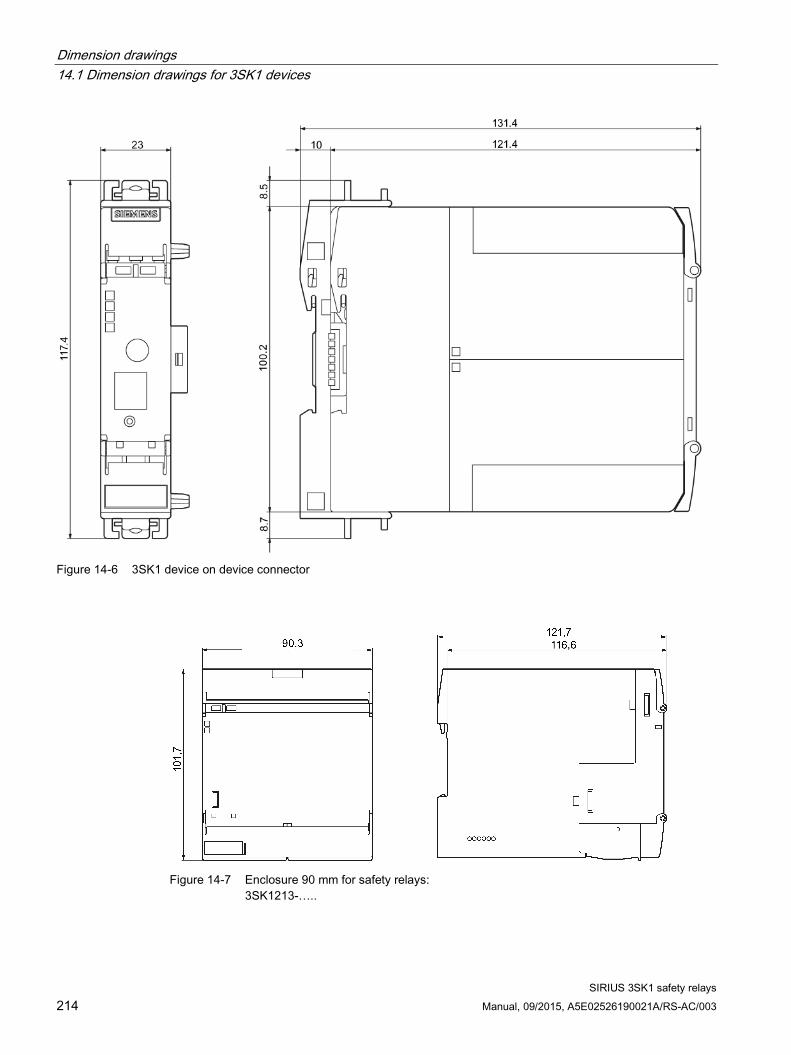
Dimension drawings 14.1 Dimension drawings for 3SK1 devices
SIRIUS 3SK1 safety relays 214 Manual, 09/2015, A5E02526190021A/RS-AC/003
Figure 14-6 3SK1 device on device connector
Figure 14-7 Enclosure 90 mm for safety relays:
3SK1213-…..

Dimension drawings 14.1 Dimension drawings for 3SK1 devices
SIRIUS 3SK1 safety relays Manual, 09/2015, A5E02526190021A/RS-AC/003 215
Figure 14-8 Drilling diagram, enclosure 90 mm

Dimension drawings 14.1 Dimension drawings for 3SK1 devices
SIRIUS 3SK1 safety relays 216 Manual, 09/2015, A5E02526190021A/RS-AC/003
Figure 14-9 3SK1213 device on device connector

Dimension drawings 14.2 Dimension drawings for 3SK1 device connector
SIRIUS 3SK1 safety relays Manual, 09/2015, A5E02526190021A/RS-AC/003 217
14.2 Dimension drawings for 3SK1 device connector
Figure 14-10 Device connector for 3SK1 safety relays, width: 17.5 mm

Dimension drawings 14.2 Dimension drawings for 3SK1 device connector
SIRIUS 3SK1 safety relays 218 Manual, 09/2015, A5E02526190021A/RS-AC/003
Figure 14-11 Device connector for 3SK1 safety relays, width: 22.5 mm

Dimension drawings 14.2 Dimension drawings for 3SK1 device connector
SIRIUS 3SK1 safety relays Manual, 09/2015, A5E02526190021A/RS-AC/003 219
Figure 14-12 Device termination connector for 3SK1 safety relays, width: 22.5 mm

Dimension drawings 14.2 Dimension drawings for 3SK1 device connector
SIRIUS 3SK1 safety relays 220 Manual, 09/2015, A5E02526190021A/RS-AC/003
Figure 14-13 Device connector for 3RM1 motor starters, width: 22.5 mm

Dimension drawings 14.2 Dimension drawings for 3SK1 device connector
SIRIUS 3SK1 safety relays Manual, 09/2015, A5E02526190021A/RS-AC/003 221
Figure 14-14 Device termination connector for 3RM1 motor starters, width: 22.5 mm

Dimension drawings 14.2 Dimension drawings for 3SK1 device connector
SIRIUS 3SK1 safety relays 222 Manual, 09/2015, A5E02526190021A/RS-AC/003
Figure 14-15 Drilling plan for 17.5 mm and 22.5 mm device connectors

SIRIUS 3SK1 safety relays Manual, 09/2015, A5E02526190021A/RS-AC/003 223
Accessories 15
The following accessories are available for the 3SK1 safety relay system. Designation Article number (MLFB) SIRIUS terminal, 2-pole, screw-type, 1 x 2.5 mm² 3ZY1121-1BA00 SIRIUS terminal, 3-pole, screw-type, 1 x 2.5 mm² 3ZY1131-1BA00 SIRIUS terminal, 2-pole, push-in, 1 x 2.5 mm² 3ZY1121-2BA00 SIRIUS terminal, 3-pole, push-in, 1 x 2.5 mm² 3ZY1131-2BA00 SIRIUS device connector for 3SK1 safety relay, 17.5 mm wide
3ZY1212-1BA00
SIRIUS device connector for 3SK1 safety relay, 22.5 mm wide
3ZY1212-2BA00
SIRIUS device termination connector for 3SK1 safety relay, 22.5 mm wide
3ZY1212-2DA00
SIRIUS device connector for 3RM1 motor starters, 22.5 mm wide
3ZY1212-2EA00
SIRIUS device termination connector for 3RM1 motor starters, 22.5 mm wide
3ZY1212-2FA00
SIRIUS device termination connector set for 3SK1 safety relay, ≥ 45 mm wide
3ZY1212-0FA01
SIRIUS device connector for looping through signals, 22.5 mm wide (for 3RM1 motor starters)
3ZY1212-2AB00
SIRIUS device connector without a function, 22.5 mm wide
3ZY1210-2AA00
SIRIUS push-in lugs for wall mounting (Contents: 12 units) 3ZY1311-0AA00 SIRIUS sealable cover, 17.5 mm 3ZY1321-1AA00 SIRIUS sealable cover, 22.5 mm 3ZY1321-2AA00 Coding pins for SIRIUS terminals 3ZY1440-1AA00 Sealable membrane 22.5 mm 1 pack = 12 membranes
3TK2820-0AA00
SIRIUS device identification label 17 sheets of 48 labels; size 10 x 7 mm
3RT2900-1SB10
SIRIUS device identification label 17 sheets of 20 labels; size 20 x 7 mm
3RT2900-1SB20
SIRIUS device identification label 10 sheets of 306 adhesive labels; size 19 x 6 mm
3RT2900-1SB60

Accessories
SIRIUS 3SK1 safety relays 224 Manual, 09/2015, A5E02526190021A/RS-AC/003
Use of removable terminals for 3SK1
The following removable terminals are available for safety relays for the prewiring of terminals in the control cabinet or for terminal replacement:
3SK1 safety relays Screw terminals Spring-type terminals (push-in)
2-pin 3-pin 2-pin 3-pin 3ZY1121-1BA00 3ZY1131-1BA00 3ZY1121-2BA00 3ZY1131-2BA00
3SK1 Advanced basic units 3SK1111 --- ✓ --- ✓ 3SK1112 ✓ --- ✓ --- 3SK1120 --- ✓ --- ✓ 3SK1121 --- ✓ --- ✓ 3SK1122 ✓ bottom ✓ top ✓ bottom ✓ top Output expansions 3SK1211 ✓ --- ✓ --- 3SK1213 --- --- --- --- Input expansions 3SK1220 --- ✓ top --- ✓ top 3SK1230 ✓ bottom --- ✓ bottom ---

SIRIUS 3SK1 safety relays Manual, 09/2015, A5E02526190021A/RS-AC/003 225
Appendix A A.1 Correction sheet
Have you noticed any errors while reading this manual? If so, please use this form to tell us about them. We welcome comments and suggestions for improvement.
Fax response From (please complete): To SIEMENS AG DF CP PRM IM 2 92220 Amberg / Germany
Name Company/Department Address
_________________________________________________________________________________
Fax: +49 (0)9621-80-3337
Manual title:
Table A- 1 Errors, comments, and suggestions for improvements

Appendix A.1 Correction sheet
SIRIUS 3SK1 safety relays 226 Manual, 09/2015, A5E02526190021A/RS-AC/003