manual tecnico linha pesada 2014 ingles - fras-le.com · technical manual - heavy duty - 4...
TRANSCRIPT

technical manual
heavy duty
english

2Technical Manual - HEAVY DUTY -
03
05
06
07
08
08
08
09
12
14
14
15
15
15
15
15
15
16
17
18
21
A World Class Company...............................................
Friction Materials Features .........................................
Stopping Distance....................................................
Braking Systems......................................................
Conserving Springs and Brake Shoes.............................
Stocking Brake Linings..............................................
Selecting Linings.....................................................
Riveting.........................................................
Brake Drums..........................................................
Brake Drum Grinding................................................
Adjustment of the Linings.........................................
Relief Valves or Fast Discharge...................................
Brake Shoe Return Springs.........................................
Predominance................................................
Replacing Brake Linings.............................................
Torque Test...........................................................
Disc Grinding..........................................................
Common Brake Failures............................................
Causes for Brake Overheating....................................
Troubleshooting.............................................
Heavy Linings – Conversion Table.................................
Table of Contents

3Technical Manual - HEAVY DUTY -
A WORLD CLASS COMPANY
High Technology
Fras-le has the largest and best equipped lab in Latin America to test its products, which are then delivered to test elds, race courses and roads, where they are approved and released for production. The entire process is followed up by Fras-le`s and OEM companies` engineers to ensure that the nal product complies with the required speci cations.
Research Lab
The Chemical Research Lab is in charge of analyzing the raw-materials for the development of new products and the improvement of existent material. At Fras-le, more than 135 different types of raw-materials are used in the production line. Speci c methods of analysis are employed in new alternative raw-materials until coming to the compounds that make up the products.
Quality Assured by Raw-Materials
The raw-materials lab is responsible for analyzing over 135 different types of raw-materials accepted into the company. It also supports production system processes and develops new suppliers. These are the most important tasks carried out by the raw-materials lab, which also develops, certi es and audits the processes used by the suppliers in order to maintain their already proven quali cation levels as Fras-le`s suppliers. The lab plays a very important role for Fras-le to gain market share, as it assures the quality of its products. This means that the raw-materials, the productive process and the tests are crucial for the safety of the products in any of their applications.
International Leadership and Technology
Established in 1954, Fras-le is engaged in the manufacturing of friction materials. Its business – Safety in Motion Control - makes of it the largest company in Latin America and one of the leading companies in the world in the eld.. It was the rst friction material manufacturer in Brazil to obtain the ISO 9001 Certi cation. Fras-le has also achieved the ISO 14001 and the ISO TS 16949. These certi cations con rm the company’s constant concern with quality, technology and environment.
Fras-le provides products with the quality of original equipment to ensure safety, ef ciency and quality to OEM companies and the Aftermarket. In its advanced Research and Development Center – one of the best equipped labs in the world – Fras-le has a chemical, physical and pilot lab that enable it to develop high-performance products. With its plant in the State of Rio Grande do Sul, distribution center in Argentina, and trade of ces in the United States, Chile, Mexico, Germany, The Arab Emirates, South Africa and China, the company maintains a trained team to meet the needs of customers located throughout more than 70 countries on ve continents where the company is present. Fras-le is a Randon Group company.

4Technical Manual - HEAVY DUTY -
Assessment
All products being developed and those in the production lines are tested in the Physical Lab, which integrates the Research and Development Center. Different pieces of equipment simulate real working conditions of raw-materials in their different applications, being instrumental in the improvement of the products until they reach the nal quality required by consumers.
The lab operates in three working shifts, continually running tests and assessing their results. The lab includes the entire process of Fras-le`s products, from development to assessment of the products in the market, from the initial tests to the nal user through speci c tests.
More than 120 different types of trials are carried out monthly in this Research and Development Center which offers the most complete testing structure in Latin America.
In Pilot Production, Quality is Assured.
In the Pilot Lab, samples are produced from customers` new needs and requests, especially OEM companies of vehicles. Experiments with new formulations are carried out. If approved, they go through all test phases until they reach the regular production lines. The Pilot Lab controls all features associated to the development of these products.
At the beginning, Fras-le has not only absorbed technology from well-known manufacturers of friction materials in the world, both European and North-American , but has also improved the global production modus operandi. State-of-the-art equipment and the company’s own culture and experience are the basic ingredients of Fras-le`s philosophy: that of developing high quality products that re ect the tradition of its brand in the market. In addition to developing its own technology, Fras-le also maintains agreements and partnerships
Motion Control: Fras-le`s Mission
In addition to research, development of materials and products, test elds are also very important to maintain quality levels. During tests, products applied to vehicles go through all situations they will possibly face when operating in real situations, on the most diversi ed road conditions. The performance of the products is also strictly followed-up by technicians who visit customers on a permanent basis. These technicians give lectures, courses and instruct retailers` clerks, mechanics and drivers so that they can use the products safely.

5Technical Manual - HEAVY DUTY - CO
EFIC
IEN
TE D
E FR
ICÇÃ
O
0,50
0,40
0,30
0,20
0,10
COEF
FICI
ENT
OF
FRIC
TIO
N
HEATINGBraking takes place at every half
minute from 90 to 0 km/h.
COOLING OR RECOVERYBraking takes place at every three
minutes from 45 to 0 km/h.
40ºC 100 160 190 210 230 250 270 290 310 320 330 340 345 350ºC 100ºC120150180200220250300
TEMPERATURE (ºC)
FRICTION MATERIALS FEATURES
Mechanical Strength
Friction material must have a mechanical strength suf cient to stand the efforts inherent to the application it is designed for. Among mechanical efforts, we highlight Compression (rubbing against the friction surfaces) and Shearing (which results from tangential forces caused by rotation movements).
Dimensional Stability
Every friction material that been heated and then cooled should keep its shape and dimensions appoximately unaltered.
The coef cient of friction is the most important factor in friction materials. Its value must be kept constant within a certain temperature range.
A high coef cient of friction does not necessarily mean quality in friction materials. Using the brake too hard is sometimes as dangerous as lack of brake. The friction stability is a crucial factor that depends on temperature, speed, pressure and external factors. Lack of brake is not necessarily caused by the friction material, but may be caused by a failure in the hydraulic or air system.
Please see below the most important features involving friction materials:
a thermal insulator to protect the deepest parts from the high temperatures generated during brake and cluck applications. Wear on friction materials is necessary to renew the friction surface, otherwise glazing may occur. On the other hand, this renewal should not happen too quickly, at the risk of affecting the durability of friction materials.
Sometimes, complaints about durability are due to problems related to the dimension of the brake ( if the drum heats too much, the working conditions have not been properly designed).
Durability
The useful life of friction materials is a very important factor that depends on the quality of the friction material selected for a certain application. One of the factors that determines the durability of friction materials is temperature.
Friction materials are bonded by organic resins that impose limitations on their working temperature. If the brakes or clutches are constantly used in high temperatures, wear on friction materials accelerates. Durability is also affected by the geometry of the brake and clutch, cast material and nish of the braking surfaces. A good quality friction material must be also
1ª 2ª 3ª 4ª 5ª 6ª 7ª 8ª 9ª 10ª 11ª 12ª 13ª 14ª 15ª 1ª 2ª 3ª 4ª 5ª 6ª 7ª 8ª
Braking Braking

6Technical Manual - HEAVY DUTY -
SPEDD in km/hSTOPPING DISTANCE IN METERS
GOOD BRAKES BAD BRAKES20 3,1 4,030 6,9 9,040 12,3 16,050 19,3 25,060 27,7 36,070 37,8 49,080 49,3 64,090 62,5 81,0100 77,2 100,0
STOPPING DISTANCEPeople react differently to obstacles or to diverse situations on traf c. When they are walking on roads, they may
react differently and unexpectedly from when they are walking on streets. Therefore, it is necessary to get familiarized with the driver`s behavior when driving on different roads.
Braking a vehicle basically depends on three factors: the vehicle, the road and the driver. A higher or lower braking ef ciency basically depends on the combination of these three factors.
Please see below a table that shows stopping distances in relation to the vehicle’s speed:

7Technical Manual - HEAVY DUTY -
Pneumatic Disc Brakes for Commercial Vehicles
They consist of oating brakes designed for use in trucks and buses as a service brake, parking brake and auxiliary brake on the rear axle and on the front axle. Brake is activated mechanically through a diaphragm cylinder or a spring cylinder, mounted onto the cover of the brake frame.
The complete disc brake, including the brake cylinder, consists on two subassemblies:
A) Brake frame;B) Brake support.
Mounting brake cylinder on brake frame results in a very compact unit.
Brake cylinder is mounted onto brake frame with the help of a ange and its activating rod is located in the brake lever. Lever and axle form an integrated unit. When cylinder is pressed, activating rod rotates the brake lever which, due to its special pro le, moves away providing constant linear movement. This linear movement of the brake lever pushes the activating mechanism towards the brake disk.
Brake activating mechanism is a device whose adjustment is automatic, progressive and variable, compensating pad wear and providing constant clearance, regardless the strength applied.
With the purpose of enhancing time intervals for pad replacement, the unit uses brake pads with a large wearable thickness. Brake design allows pads to be replaced quick and easy. This enables optimization of mounting conditions, for example, a good observation angle of the assembly.
BRAKING SYSTEMS
Pres
sure
Compressed Air
Área Force
Fig. 01
Motor Brakes
Their actuation takes place on the motor exhaust system, by partial obstruction of gas release, by means of a butter y valve. Thus, motor offers resistance to vehicle displacement.
Retarders
Retarder is a braking mechanism whose function is to reduce or stabilize a vehicle speed, especially down slope without stopping it.
Retarders can be placed between the engine (motor) and the gearbox (primary retarders) or between the gearbox and the traction axles (secondary retarders).
There are two basic conceptions for retarding brake mechanism:
a) Hydrodynamic retarder b) Electromagnetic retarder
Compressed Air Brakes
Because of the versatility of this uid, it is used for heavy vehicles, where the hydraulic system is not recommended, due to the high pressure demanded for braking ef ciency. Consequently, hydraulic system would present a limited lifespan on its sealing, resulting in frequent changes, besides likely dangerous leakage. The driver can control, through the brake pedal, the pressure that will be exerted on the pneumatic cylinders (Figure 01).

8Technical Manual - HEAVY DUTY -
g. 04 g. 03
B
AC
g. 02
It has been observed that many technicians in charge of eet maintenance do not pay enough attention to the warping state of the brake shoes. Because of this, we present two jigs to help keep the brake shoes in good condition.
Warped brake shoes lead to vibrations, which are noticed as noise.
Deformed brake shoes can cause brake linings to break when they are being riveted. When system is working, brake shoe warping takes to ineffectiveness of braking, or chatter, and it may even cause brake linings to be loosened.
Professionals can easily avoid these problems by periodically checking the brake shoes. See drawing (Figure 04). It shows what parts are necessary to control warped brake shoes. The drawing (Figure 06) shows the order to put parts to assemble the jig.
In the drawing (Figure 02), you can see a part to control brake shoe radius. Note that the distance marked between the dots (letters) indicates dimensions to be checked by the jig, ranging from one model to another according to brake shoe dimensions of each vehicle. Another important point to check is the housing for the brake shoe anchorage bolts, which should not present any deformations.
Brake shoe return springs should be checked, so that they can fully return when brake is released. It is mandatory that return springs be replaced whenever any clearance is perceived between the brake shoe and the expander, because such clearances can cause vibration and noises.
Rivet xing holes should be checked. Its oval shape or an increase of its diameter may cause loose linings because of braking effort.
CONSERVING SPRINGS AND BRAKE SHOES
Brake linings are manufactured in accordance with technical speci cations for each vehicle. There are hundreds of different presentations for brake systems and linings are manufactured so as to meet performance requirements of the vehicles as well as their speci c designs.
Each brake system has speci c curvature for its brake shoes, and brake linings are manufactured so that they t this curvature perfectly.
To prevent any deformation on the friction material, once it would make it dif cult or even impossible to assemble it correctly on the brake shoes, it is recommended that such material be always stocked with parts placed side by side (see Figure 03).
Never stock linings by piling them one over the other with their curvature facing down (or up), since the weight of the pile tends to deform the parts that are at the bottom (see Figure 04).
STOCKING BRAKE LININGS
We manufacture linings for each kind of vehicle, considering its building characteristics and its usage.
Therefore, for city vehicles, road transporting vehicles and passenger vehicles, we offer different linings that aim at a better performance in each condition.
Make sure you are using the correct lining for your case, consulting the Application Catalog and checking the reference identi cation stamped on the lining. This reference is usually on the side of the linings.
Never mix linings of different makes and quality, because each compound has a peculiar chemical characteristic and their combination without technical orientation may lead to unpredictable consequences.
SELECTING LININGS

9Technical Manual - HEAVY DUTY -
RIVETING
g. 06
12
3
g. 07
g. 05
Here are some steps that establish the correct procedure for riveting linings onto shoe brakes for auto-vehicles:
1- Check for geometry of brake shoe as for distortions / aws such as: base warping, welding break between grooves and base, diameter of holes, etc.;
2- Make sure brake lining to be riveted is the one recommended by manufacturer of the vehicle;
3- Check for brake drum conditions as for wearing, grooves and thermal cracks. Should it be necessary, part is machined or simply replaced by a new one. Pay special attention to machining brake drums, because linings should be thicker (oversized), “X” or “XX”, compatible with the new diameter of the drum;
4- Brake drum machining should comply with dimensions allowed by the manufacturer. This dimension is stamped on the brake shoe. It is important that both drums of same axle be the same diameter. It is convenient to remember that brake drum grinding reduces its mechanical strength and its thermal capacity;
5- It is very important that vehicle be assembled on all its axles with brake linings of the same make and quality;
6 - Before riveting, check laying between the lining and the brake shoe. A 0.25 mm clearance (maximum) is acceptable between the brake shoe and the lining, along sides and ends of the assembly, except for the pair of grooves, where up to 0.64 mm clearance is acceptable (Figure 05);
7- Make sure rivets have correct rod diameter, head size, shape, length and material. For this purpose, we
have a catalog for brake lining application where we recommend the perfect kind of rivet as per brake assembler speci cation;
8- It is recommended that brass or brass steel be used because of its mechanical, resistance and expansion properties;
9- It is recommended that semi-tubular or tubular rivets be used, due to better riveting;
10- For drum brakes of large vehicles, which need rivets whose diameter range from 6.2 to 8.0 mm, it is considered that free length for good riveting is 4.5 to 5.5 mm. This dimension is usually given as follows: 0.75 x rivet diameter (Figure 06);
1. Free length for riveting is too short. 2. Free length for riveting is correct.3. Free length for riveting is too long.
Clearance between lining and brake shoe should not exceed 0.64 mmbetween grooves at both ends.
Clearance between lining and brake shoe should not exceed 0.25 mm at both ends.
Clearance between lining and brake shoe should not exceed 0.25 mm at both ends.

10Technical Manual - HEAVY DUTY -
16 - Rivet should ll holes in the lining and in the brake shoe (Figure 10);17 - Tubular length of the rivet should be deep enough to prevent riveting punch from nding any resistance(Figure 11);
Acceptable Unacceptable
g. 08
g. 09
g. 10
Acceptable Unacceptable
Below, you will nd a table for rivets, presenting main gauges and their respective dimensions.
11 - Riveting machine should be a device that enables controlling pressure exerted over the rivet. Activation may be either hydraulic or pneumatic;
Rivet Brake Drum Grinding
12 - Make sure brake shoe and lining contact faces are clean;
13 - Inserting the rivet should be easy, not offering any resistance;
14 - Make sure rivet head does not have any cracks which may impair its resistance (Figure 08);
15 - Before installing brake linings on brake shoes, check compressed height of the rivet. Press rivet in the riveting machine and measure distance “A” (Figure 09);
MARCA DO VEÍCULO REFERÊNCIA DA LONA FRAS-LE TIPO DE REBITE
AGRALE
287 4 - 42006-T, 2080-T 4 - 52042-A, FD/71, FD/72 7 - 6FD/77 10 - 8
CARRETAS e3º EIXOS
4514-F, 4515-C, 4515-G, 4717, CA/32, CA/33, FD/81 10 - 10SV/223, SV226 10 - 124195-B 10 - 14
CHRYSLER
2026-AT 4 - 5659-B, 2042-A, 2060, FD/72, FD/73 7 - 64564-A 7 - 84514-F 10 - 10
FIAT
FI/95 7 -FI/92, FI/93, FI/94, FI117 10 -4514-F, 4515-C, 4524-B, FN/116 10 - 10FI/115 13 -
FNM4514-F, 4515-C, 4524-B, FN/116 10 - 10FN/106, FN/107 13 - 14
FORD
2026-AT, 2026-T, FD/78 4 - 52032, 2042, 2042-A, 2060, FD/71, FD/72, FD/73, FD/74 7 - 64564-A, FD/75, FD/76 7 - 8FD/79, FD/80 10 -4505-A, FD/77 10 - 8
4514-F, 4515-G 4710, FD/83, FD/84, FD/85, FD/86, FD/87, FD/88 10 - 10
GM
2095 4 - 52039 5 - 5659-B, 2032, FD/72, FD/74, VW256, VW257 7 - 6CB/36, FD/75 7 - 8
4514-F, 4524-B, 4707, CB/53, CB/54 FD/83, FD/84, FD/85, FD/86 10 - 10
INTERNATIONAL659-B 7 - 64514-F, 4515-C, 4524-B, 4707, 4720 10 - 10
IVECO 4515-G, CA/32, FD/86, FD/87, FD/88 10 - 10
MARCOPOLOFD/72 7 - 6FD/77 10 - 8
MB
MB/157 4 - 5MB/155 7 - 64515 8 - 10MB/188, MB/190, MB/191 8 x 20FD/77 10 - 8
MB/161, MB/164, MB/167, MB/176, MB/177, MB/179, MB/180, MB/181, MB/182 13 - 10
MB/183, MB/184, MB/185 8 - 20
PUMA2026-AT 4 - 5FD/72 7 - 6
SCANIA SV/222, SV/223, SV/224, SV/226, SV/227, SV/228, SV/229, SV/230, SV/231 10 - 12
VOLVOVV/288, VV/289, VV/290 VOLVO VV/296, VV/298, VV/299, VV/300, VV/303, VV/304 10 - 10
VW
VW/256, VW/257 7 - 6FD/80, FI/117 10 -FD/77 10 - 8
4514-G, 4524-B, 4710, FD/83, FD/84, FD/86, FD/87, FD/88, FI/118, FI/119 10 - 10
VW/225 13 -
TIPO DEREBITE
DIMENSÕES - mm DIMENSÕES - mm
A B C A B C4 - 3 3.6 4.8 8.0 9/64 3/16 5/16
4 - 4 3.6 6.4 8.0 9/64 1/4 5/16
4 - 5 3.6 8.0 8.0 9/64 5/16 5/16
4 - 6 3.6 9.5 8.0 9/64 3/8 5/16
4 - 7 3.6 11.0 8.0 9/64 7/16 5/16
5 - 4 3.6 6.4 9.5 9/64 1/4 3/8
5 - 5 3.6 8.0 9.5 9/64 5/16 3/8
5 - 6 3.6 9.5 9.5 9/64 3/8 3/8
5 - 7 3.6 11.0 9.5 9/64 7/16 3/8
6 - 16 6.0 16.0 16.0 5/8 5/8
7 - 3 4.8 4.8 9.5 3/16 3/16 3/8
7 - 4 4.8 6.4 9.5 3/16 1/4 3/8
7 - 5 4.8 8.0 9.5 3/16 5/16 3/8
7 - 6 4.8 9.5 9.5 3/16 3/8 3/8
7 - 7 4.8 11.0 9.5 3/16 7/16 3/8
7 - 8 4.8 13.0 9.5 3/16 1/2 3/8
7 - 10 4.8 16.0 9.5 3/16 5/8 3/8
7 - 12 4.8 19.0 9.5 3/16 3/4 3/8
8 - 8 4.8 13.0 13.0 3/16 1/2 1/2
8 - 10 4.8 16.0 13.0 3/16 5/8 1/2
8 - 12 4.8 19.0 13.0 3/16 3/4 1/2
8 - 14 4.8 22.0 13.0 3/16 7/8 1/2
8 - 16 4.8 25.0 13.0 3/16 1 1/2
10 - 6 6.4 9.5 13.0 1/4 3/8 1/2
10 - 8 6.4 13.0 13.0 1/4 1/2 1/2
10 - 10 6.4 16.0 13.0 1/4 5/8 1/2
10 - 12 6.4 19.0 13.0 1/4 3/4 1/2
10 - 14 6.4 22.0 13.0 1/4 7/8 1/2
10 - 16 6.4 25.0 13.0 1/4 1 1/2
11 - 5 4.0 8.0 8.0 5/32 5/16 5/16
13 - 10 8.0 16.0 16.0 5/16 5/8 5/8
13 - 12 8.0 19.0 16.0 5/16 3/4 5/8
13 - 14 8.0 22.0 14.0 5/16 7/8 9/16
13 - 16 8.0 25.0 14.0 5/16 1 9/16
8 x 15 8.0 15.0 16.0
8 x 16 8.0 16.0 16.0
8 x 18 8.0 18.0 16.0
8 x 20 8.0 20.0 16.0
8 x 22 8.0 22.0 16.0
VOLVO 6.2 19.0 12.5

11Technical Manual - HEAVY DUTY -
g. 12
Unacceptable
g. 13
g. 18
18 - Install rivets on the holes and perform as per sequence (Figure 12);
Drawing of riveting punch for 8.0 mm diameter rivet
7º 1º 2º 8º
9º 3º 4º 10º
11º 5º 6º 12º
g. 11
19 - Riveting force should not be brisk but slow, within approximately 2 seconds, keeping the pressure for 1 second. This operation aims at preventing any cracks on the brake linings and clearances between them and the brake shoe;
20 - After riveting, maximum clearance admitted is 0.10 mm, whereas none of the areas for laying rivets should present any clearances. It may be admitted at the corners;
21 - Loose rivets are not acceptable (Figure 13)Checking limit:-Minimum: rivet moves when forced manually;-Maximum: rivet moves when hit a small hammer.
22-Riveting strength recommended for 6.2 and 8.0 diameter rivets, either semi-tubular, in brass or brass steel, ranges from 1,700 to 2,400 kgf, ehwreas strength will be larger according to the larger diameter of the rivet body.
Drawing of riveting punch for 6.3 mm diameter rivet
The wear indicator has the main function to facilitate the identi cation of useful life of a brake lining, that is, so far as it can be used. Below this indicator (recess) are the rivets, that can damage the drum if the brake lining is used more than this limit. ( gure)
Perform periodic veri cations on the brake linings making the change when the wear of the brake lining be on the same level of the recess from de wear indicator.NOTE: Do not forget to check the drum diameter when changing the brake linings. Always use rivets indicated by the manufacturer.
WEAR INDICATOR
12Technical Manual - HEAVY DUTY -
g. 14
g. 15
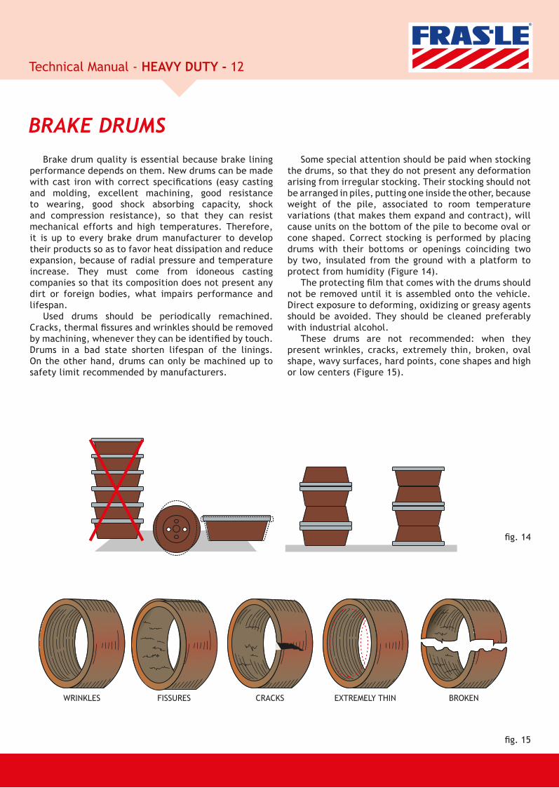
Brake drum quality is essential because brake lining performance depends on them. New drums can be made with cast iron with correct speci cations (easy casting and molding, excellent machining, good resistance to wearing, good shock absorbing capacity, shock and compression resistance), so that they can resist mechanical efforts and high temperatures. Therefore, it is up to every brake drum manufacturer to develop their products so as to favor heat dissipation and reduce expansion, because of radial pressure and temperature increase. They must come from idoneous casting companies so that its composition does not present any dirt or foreign bodies, what impairs performance and lifespan.
Used drums should be periodically remachined. Cracks, thermal ssures and wrinkles should be removed by machining, whenever they can be identi ed by touch. Drums in a bad state shorten lifespan of the linings. On the other hand, drums can only be machined up to safety limit recommended by manufacturers.
BRAKE DRUMSSome special attention should be paid when stocking
the drums, so that they do not present any deformation arising from irregular stocking. Their stocking should not be arranged in piles, putting one inside the other, because weight of the pile, associated to room temperature variations (that makes them expand and contract), will cause units on the bottom of the pile to become oval or cone shaped. Correct stocking is performed by placing drums with their bottoms or openings coinciding two by two, insulated from the ground with a platform to protect from humidity (Figure 14).
The protecting lm that comes with the drums should not be removed until it is assembled onto the vehicle. Direct exposure to deforming, oxidizing or greasy agents should be avoided. They should be cleaned preferably with industrial alcohol.
These drums are not recommended: when they present wrinkles, cracks, extremely thin, broken, oval shape, wavy surfaces, hard points, cone shapes and high or low centers (Figure 15).
WRINKLES FISSURES CRACKS EXTREMELY THIN BROKEN

13Technical Manual - HEAVY DUTY -
g. 16
g. 17
Normal usage of brake systems always takes to wear on drums friction-traveling course. However, whenever drum surface wear is noticed by touch, it is recommended that friction-traveling course be machined. By following these procedures, we will keep the friction-traveling course, as uniform as possible and system performance will be optimized.
Linings are manufactured in several thicknesses for the same reference or model. These different thicknesses are to be used according to the increase in the diameter of the drum because of wearing and/or machining.
In order to know which thickness to be used on machined drum is correct, it is necessary to know the diameter after machining. Thus, in a very simple way, we can show, in the example, how to measure internal diameter of the drums, with a variation of one single “quote X” checked with a pressure gauge.
In the drawing below (Figure 16), you can check all the parts necessary to assemble a gauge.
Now you will nd out how to assemble it, by simply following the schematic below (Figure 17).
To obtain this result, you will have to follow these procedures: assemble locknut C on rod A and then rod B and nally rod B on part A’s thread. Doing so, you have the device required to measure internal diameter of the brake drum, without forgetting that “quote X” is the measure you are looking for. Do not forget to perform thermal treatment at ends 01 and 02.
Summarizing:Sum of standard measures: 378 mmFor 410 mm drums x = 32 mmFor 408 mm drums x = 30 mmFor 418 mm drums x = 40 mm
Thre
ad 1
0x1
Thre
ad 1
0x1M
illing ø
C (Locknut)
Standard measure 194 Standard measure 184
x-measure to be confirmed on the gauge according to dimension or variation of the drum.

14Technical Manual - HEAVY DUTY -
Vehicle BrandDiameter of the Drums - mm
Normal Linning Linning with One Oversize (x)
Linning with Two Oversizes (xx)
AGRALE 325,0 327,0
CARRETAS
381,0 384,2 387,4
413,0 416,2
419,0 422,2
FIAT
381,0 384,2 387,4
394,0 397,2
419,0 422,2
FORD
305,0 306,6
308,0 309,6
325,0 327,0
330,0 333,2
356,0 359,2
381,0 384,2 387,4
394,0 397,2
406,0 409,2
419,0 422,2
GM
356,0 359,2
381,0 384,2 387,4
394,0 397,2
406,0 409,2
419,0 422,2
INTERNATIONAL406,0 409,2
419,0 422,2
IVECO381,0 384,2 387,4
419,0 422,2
MARCOPOLO325,0 327,0
330,0 331,6
MB
280,0 281,8
300,0 301,0 302,0
304,0 305,0 306,0
325,0 327,0
408,0 410,0 412,0
410,0 412,0 414,0
418,0 420,0 422,0
PUMA 330,0 331,6
SCANIA 413,0 416,2
VOLVO394,0 397,2
410,0 412,0 414,0
VW
325,0 327,0
381,0 384,2 387,4
394,0 397,2
419,0 422,2
For the first oversize of the drums, linings of the first oversize (X) must be used and for the second oversize when recommended by the manufacturers, linings of the second oversize should be used. Standard linings should never be used on remachined drums (first
BRAKE DRUM GRINDING and second over sizes), since there will not be full contact between linings and brake drums, resulting in ineffectiveness, glazing and/or noise, because of the overheating of the lining surfaces contacting the drum.
It is important to keep correct adjustment of the linings as to the drums. Only by doing so, can one assure quick response, effective braking and total usage of friction material. Adjustment should be uniform on all wheels. That way, vehicle will not present any tendency to pull to any side during braking and usage will be complete and homogeneous. Special care must be given so that linings do not abrade the drums, because this will increase brake temperature (larger wear, smaller effectiveness) and even cause glazing or swelling (increase of volume with occasional wheel blocking).
To facilitate adjustment tasks, there are some adjusters in the market that can adjust, through an automatic mechanism, the distance between the linings and brake drums (Figure 18).
Please nd below the description for replacing linings for brakes that have these adjusters and for the torque test, to evaluate whether the functioning and mechanism of these adjusters are in perfect condition.
Brake linings should be adjusted so that they do not touch drums when vehicle runs freely. Because of a possible ovalization of the drums, resulting from wearing and efforts that are subject to, this adjustment should be performed with the respective axle up.
With the vehicle touching the ground, it is not possible to check for contact points of the drum with the linings during break-in.
On those combined units (truck + tractor trailer), when adjusting tractor-trailer linings, it is necessary to adjust truck linings. It is very common to nd in the market a practice that consists on leaving the truck brake linings intentionally farther than the tractor-trailer, so that the truck will have to brake less. This practice is harmful to the safety of the assembly and it may cause several problems.
ADJUSTMENT OF THE LININGS

15Technical Manual - HEAVY DUTY -
ManualAdjuster
g. 18
Whenever brake pedal is released after braking, these valves have the function of releasing the air that is inside brake chambers quickly. Otherwise, brakes will be applied
These springs get tired with usage, especially when they are exposed to excessive heat. When they lose their tension, they end up allowing constant contact of the
PREDOMINANCE Do not make any changes on the original adjustment
of pressure gauge valve that connects tractor-trailer to the truck. Should you have any questions, consult vehicle
for longer than necessary, generating unwanted wear and heat. For so, operation of these valves should be checked periodically and whenever there are any problems of overheating.
linings with the brake drums, and this may even cause, besides unnecessary heating and wearing, self-blocking (by the action of the lining contacting drums at high rotation).
manufacturer either contacting company directly or through its service agencies.
RELIEF VALVES OR FAST DISCHARGE
BRAKE SHOE RETURN SPRINGS
In order to replace brake linings, follow these steps:
1. Rotate six-headed threadless bolt of the brake automatic adjuster counter clockwise, until S-cam is totally retrieved. During the operation, you will hear a peculiar noise, which is perfectly normal.
It is not necessary to remove the bolt from the cylinder rod neither loosen setscrew from control arm.
2. Replace linings, assemble drum and check clearance between linings and drums (it should be larger than speci ed).
Rotate six-headed threadless bolt clockwise, until linings touch brake drum. Open clearance between linings and drum rotating six-headed bolt again for ¾ turn counter clockwise. This is a pre adjustment of the clearance. (Figure 24).
3. Perform some brakings before you release the vehicle, so that the automatic brake adjuster performs the ne adjustment of the clearance to the speci ed value.
REPLACING BRAKE LININGS
TORQUE TEST
Brake disc friction surfaces act directly on pad lifespan. Cracks, thermal ssures and grooves should be removed by machining these surfaces every time they can be felt by touch. On the other hand, brake discs should only be
DISC GRINDINGmachined up to the safety limit recommended by the manufacturer. It is recommended that discs be replaced whenever actual thickness of the part is similar to or lower than dimension stamped on the disc.
With brake relieved and without removing vehicle adjuster, place a torquemeter on the six-headed threadless bolt, rotate torquemeter counter clockwise and monitor internal conical coupling so that it does not come off at torque lower than 18 Nm (1.8 kgm).
A peculiar noise takes place when this test is carried out. Repeat operation three times with each lever. Should coupling come off at a lower torque, replace or recover automatic adjuster.
16Technical Manual - HEAVY DUTY -
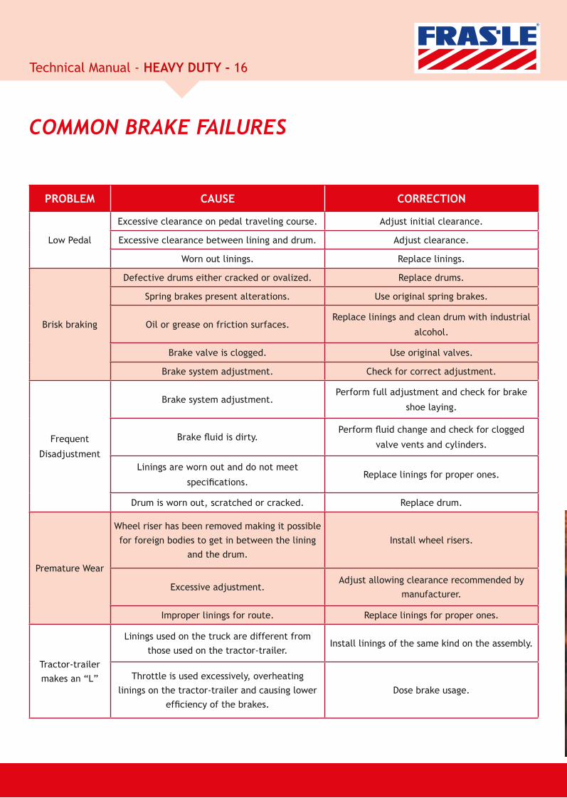
PROBLEM CAUSE CORRECTION
Low Pedal
Excessive clearance on pedal traveling course. Adjust initial clearance.
Excessive clearance between lining and drum. Adjust clearance.
Worn out linings. Replace linings.
Brisk braking
Defective drums either cracked or ovalized. Replace drums.
Spring brakes present alterations. Use original spring brakes.
Oil or grease on friction surfaces.Replace linings and clean drum with industrial
alcohol.
Brake valve is clogged. Use original valves.
Brake system adjustment. Check for correct adjustment.
Frequent
Disadjustment
Brake system adjustment.Perform full adjustment and check for brake
shoe laying.
Brake uid is dirty.Perform uid change and check for clogged
valve vents and cylinders.
Linings are worn out and do not meet
speci cations.Replace linings for proper ones.
Drum is worn out, scratched or cracked. Replace drum.
Premature Wear
Wheel riser has been removed making it possible for foreign bodies to get in between the lining
and the drum.Install wheel risers.
Excessive adjustment.Adjust allowing clearance recommended by
manufacturer.
Improper linings for route. Replace linings for proper ones.
Tractor-trailer makes an “L”
Linings used on the truck are different from those used on the tractor-trailer.
Install linings of the same kind on the assembly.
Throttle is used excessively, overheating linings on the tractor-trailer and causing lower
ef ciency of the brakes.Dose brake usage.
COMMON BRAKE FAILURES
17Technical Manual - HEAVY DUTY -
Operational
City traf c in large cities requires brakes to be used more frequently, many times associated to an aggressive driving behavior, caused by stress;
Mountain regions also require brakes to be used more intensively when good driving rules such as using motor brake correctly, going downhill on proper gear, etc. are not respected;
Transporting excessive load increases kinetic energy of the vehicle considerably, causing heat to concentrate on the brakes during braking;
Speeding or performing certain speed that is not compatible with traf c or road conditions also stresses out the brake usage, generating more heat concentration on them;
When referring to coupled assemblies: truck + tractor-trailer, the improper and abusive use of the brakes through the throttle forces the brake system of the implements, concentrating excessive heat on the brakes and even resulting into serious consequences;
Ignoring motor brakes when going down slopes or when stopping the vehicle causes service brakes to be used more intensively, generating excessive heating that could have easily been avoided.
Disrespecting minimum distance recommended to be kept from vehicle riding in the front, and which is variable according to the speed being employed, leads to a frequent use of the service brakes.
CAUSES FOR BRAKE OVERHEATING
Maintenance
It is important to point out that all the above-mentioned are highly harmful, even when they apply to vehicles in good state. Should they have any defective or deregulated parts, whether that means on vehicle suspension or its brakes, risks of accidents just multiply.
Correct maintenance of brakes is essential for safety and life span of every component. Do not forget that the brakes are an assembly and not an isolated element and they should be checked as an assembly.
Most trucks are equipped with a valve that allows a differential of pressure between brake circuits of the truck and the tractor-trailer; that is, it allows a slightly different pressure to be exerted on the tractor-trailer compared to the one being exerted on the truck (within 0.15 and 0.6 bar, depending on vehicle manufacturer). Some of these valves allow adjustments and others don’t. This adjustment frequently reaches something from 1 to 1.5 bar (which is often done inadvertently) and this causes brakes to be used more than they should be and, consequently, become overheated.

18Technical Manual - HEAVY DUTY -
TROUBLESHOOTING
PROBLEM CAUSE CORRECTION
VEHICLE DOES NOT COME TO A HALT
Brake governor not adjusted. Adjust brake governor.Master cylinder presents internal leakage. Perform another repair or replace defective assembly.
Air intake lters are obstructed. Replace lters.
Leakage of uid or compressed air (low pressure). Replace damaged components.
Circle is obstructed. Unblock air passage.Pneumatic-hydraulic chamber has torn
diaphragm. Repair chamber, replace diaphragm bed.
Clip piston or wheel cylinder blocked. Perform another repair or replace defective assembly.Brake drum is not adjusted. Adjust drum brakes.-Improper linings or pads.
-There is grease or oil on the linings or pads.
-Pad or lining glazing.-Linings or pads are not laying.
Replace linings or pads.
Vehicle has been overloaded. Carry load according to speci ed limits.
Pedal valve is defective. Identify defect and repair it.
Compressor is defective. Check for defect and repair it.
VEHICLE WHEELS ARE BLOCKED
Relief vents for compressed air on valves is obstructed. Repair relief valves.
Relief vents for compressed air on valves is obstructed. Unblock relief vents for compressed air on valves.
Pneumatic hydraulic chamber rod does not return.
Pneumatic hydraulic chamber spring is broken.
Replace chamber.
Hoses or pipes are obstructed. Unblock channels, replacing damaged components.Low pressure on spring brake chamber. Check compressor governor and piping conditions.
Parking brake has been pre activated. Repair or replace spring brake.
Brake shoe return spring is wear. Over adjustment of drum brake.
Replace springs. Adjust brakes carrectly.
Brake pistons are blocked. Replace internal repair when casing does not present any internal corrosion. Otherwise, replace, hydraulic assembly.
Ovalized drum. Grind or replace brake drum.
Pedal valve is blocked. Repair or replace valve.
Friction materials (pads and linings) are responsible for wheel deceleration. Therefore, any damage or nonconformity on the material will jeopardize stopping distance directly.
Whenever there is any kind of disadjustment on the drum brakes, pressurization becomes slower, pedal has a longer traveling course and, therefore, vehicle has trouble to come to a halt. Should that happen, adjust brakes correctly. There may be other reasons causing failure and dif culties on depressing brakes on the wheels.
NOTE: Should the vehicle be carrying some overload or an excessive number of passengers, it means more effort from the driver and braking system, which will not allow a safe braking with a smaller stopping distance.
Incorrect adjustment on regulator can cause wheel blocking.
PROBLEM CAUSE CORRECTION

19Technical Manual - HEAVY DUTY -
VEHICLE PULLS TO ONE SIDE
Tire conditions are unequal. Use tires with identical conditions on each axle.Disc thickness is unequal. Use discs with the same thickness.
One of the brakes presents uid obstruction.
Check brake activation and eliminate obstruction by replacing defective part.
Linings or pads of different make. Replace linings and pads.Different drum diameter. Use drums with the same diameter.
Brake blocking in one side. Check defective component and perform maintenance.Brake adjustment is unequal. Adjust brakes correctly.
Drum brake springs have uneven loads. Perform new repair on springs.
Oil or grease in one of brakes. Repair leakage, clean components and replace contaminated friction material.
VEHICLE DOES NOT STAND STILL
Parking brake-activating valve is defective. Repair or replace brake-activating valve.
Parking brake cable is damaged. Replace cable.There is grease or oil on the linings. Replace linings.
Brakes are misadjusted. Adjust brakes correctly.Parking brake spring is weak or
broken. Repair spring brake.
Parking brake linings are inappropriate. Replace linings.
Whenever there are any differences between LH side and RH right side of front axle, whether on suspension or on brakes, this can cause side pulls. The rst step to avoid such problem is to always have brakes serviced axle by axle and keeping the same condition on both sides. Some factors that may contribute for defects and that aren’t part of brake systems:
•Tires have been gauged with different calipers or have different conditions.•Steering wheel alignment is irregular (convergence and caster brake are non conformant with speci cation).•Front wheel hub rolling bearings are damaged or loose.•Front suspension or steering wheel bar are damaged or loose.
Using non-genuine springs, linings and diaphragms prevent parking brake assembly from working properly.
PROBLEM CAUSE CORRECTION
PROBLEM CAUSE CORRECTION
20Technical Manual - HEAVY DUTY -
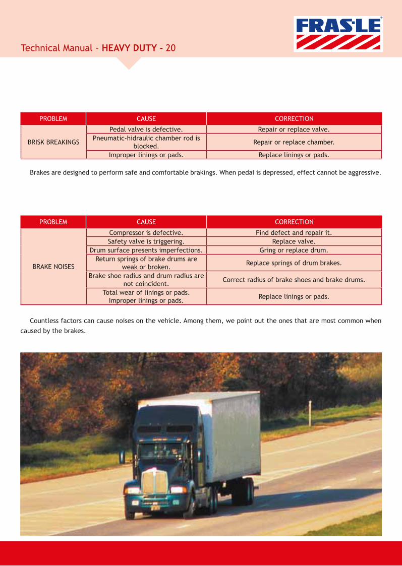
BRAKE NOISES
Compressor is defective. Find defect and repair it.Safety valve is triggering. Replace valve.
Drum surface presents imperfections. Gring or replace drum.Return springs of brake drums are
weak or broken. Replace springs of drum brakes.
Brake shoe radius and drum radius are not coincident. Correct radius of brake shoes and brake drums.
Total wear of linings or pads. Improper linings or pads. Replace linings or pads.
PROBLEM CAUSE CORRECTION
BRISK BREAKINGS
Pedal valve is defective. Repair or replace valve.Pneumatic-hidraulic chamber rod is
blocked. Repair or replace chamber.
Improper linings or pads. Replace linings or pads.
Brakes are designed to perform safe and comfortable brakings. When pedal is depressed, effect cannot be aggressive.
Countless factors can cause noises on the vehicle. Among them, we point out the ones that are most common when caused by the brakes.
PROBLEM CAUSE CORRECTION

21Technical Manual - HEAVY DUTY -
HEAVY LININGS – CONVERSION TABLEFRAS-LE LONAFLEX BENDIX BOSCH THERMOID COBREQ FRAS-LE LONAFLEX BENDIX BOSCH THERMOID COBREQ
659-B L-510 HQ-123 BE 0410 659B
2026-AT L-529 BE 0386
2026-T L-189 HQ-104 BE 0104 2026T
2032 L-110
2039 L-146 HQ-119 BE 0409
2042 L-147 BE 0378
2042-A L-533 HQ-105 BE 0105 TH-99 0435
2060 L-202 BE 0408
4195-B L-378 BNA-328 BE 0328 TH-4195B 4195B
4375 L-587
4480 L-885
4354-A L-588
4514-F L-136-A BNA-312 BE 0312 TH-4514 4514T
4514-G L-136-K BNA-335 BE 0335 TH-157 4514GD
4515 L-157 BE 0388
4515-C L-157-A BNA-313 BE 0313 TH-4515 4515T
4515-G L-157-O BNA-306 BE 0306 TH-151 4515FC
4524-B L-502 BNA-301 BE 0301 TH-54 4524FT
4564-A L-140 BE 0389
4707 L-641 BE/BD 0390 TH-205
4710 L-640 BNA-389 BE/BD 0391 TH-191 4710T
4718 L-639 BE/BD 0392 TH-4718 4718T
4720 L-642 BE/BD 0393
CA/32 L-638 BNA-329 BE/BD 0329 TH-4516 4644T
CA/33 L-636 BE/BD 0394 TH-204 4533T
CA/36 L-635
CB/36 L-361 HQ-102 BE 0411 TH-15
CB/53 L-142 BNA-310 BE 0310 TH-152
CB/54 L-144 BNA-311 BE 0311 TH-153
FD/58 L-562 BE 0418 TH-258 0822T
FD/59 L-559 BE 0419 TH-259 0821T
FD/71 L-535 BE 0395 0470T
FD/72 L-577 HQ-115 BE 0115 TH-93 0428
FD/73 L-534 HQ-120 BE 0412 TH-72 / 73
FD/74 L-523 HQ-114 BE 0114 TH-697C 0413A
FD/75 L-524 BNA-309 BE 0309 TH-92 / 112 1252
FD/76 L-488 BE 0124
FD/77 L-219 BE/BD 0396 TH-202 0811T
FD/78 L-658 BD 0413
FD/80 L-661 BNA-304 BE 0304 TH-117 0440
FD/81 L-637 BNA-385 BE 0385 TH-187
FD/82 L-655 BE 0397
FD/83 L-728 BNA-308 BE 0308 TH-150 0463T
FD/84 L-220 BNA-371 BE 0371 TH-167 0464T
FD/85 L-221 BNA-376 BE 0376 TH-175 0466T
FD/86 L-222 BNA-372 BE 0372 TH-174 0812T
FD/87 L-223 BNA373 BE/BD 0373 TH-165 0814T
FD/88 L-224 BNA-374 BE/BD 0374 TH-166 0815T
FI/117 L-627 BNA-305 BE 0305 TH-122 0448
FI/118 L-225 BNA-375 BE 375 TH-171
FI/119 L-226 BNA-380 BE 0380 TH-170
FN/107 L-103-A BE 0398
IV/158 L-736
MB/157 L-115 BE 0414
MB/161 L-101 TH-18 0322
MB/164 L-102 TH-19 0319
MB/176 L-348 BNA-321 BE 0321 TH-22 0111
MB/177 L-652-B BNA-314 BE 0314 TH-141
MB/179 L-633 BNA-322 BE 0322 TH-37A
MB/180 L-501 BNA-323 BE 0323 TH-37 0326
MB/181 L-509 BNA-324 BE 0324 TH-38 0327
MB/182 L-652 BNA-316 BE 0316 TH-136 0132T
MB/183 L-651 BNA-315 BE/BD 0315 TH-134 0133T
MB/184 L-552 BNA-319 BE/BD 0319 TH-133 0134T
MB/185 L-551 BNA-317 BE/BD 0317 TH-132 0135T
MB/186 L-522 HQ-125 BE 0125 TH-74 / 75 0422
MB/187 L-522-E HQ-126 BE 0126 TH-131 0422A
MB/188 L-227 BNA-370 BE/BD 0370 TH-164 0137T
MB/190 L-131 BNA-336 BE/BD 0336 TH-148 0140T
MB/191 L-133 BNA-337 BE/BD 0337 TH-142 0141T
MB/193 L-586 BE/BD 0399 TH-161 0124T
MB/194 L-511
MB/195 L-512
SV/223 L-107 BNA-325 BE/BD 0325 TH-12 0461
SV/224 L-311 BNA-326 BE/BD 0326 TH-11 0462
SV/226 L-497 BNA-327 BE/BD 0327 TH-67 0418
SV/227 L-499 BNA-338 BE/BD 0338 TH-143 0710
SV/228 L-307 BE/BD 0400 TH-178 0711
SV/229 L-308 BNA-392 BE/BD 0401 TH-180 0712
SV/230 L-309 BNA-387 BE/BD 0402 TH-179 0713
SV/231 L-310 BNA-388 BE/BD 0403 TH-181 0714
TR/311 L-546
TR/313 L-576
TR/315 L-596
TR/328 L-679
TR/330-S/F
TR/348 L-1044
TR/368 L-1047
VV/288 L-663 BNA-330 BE/BD 0330 TH-4517 0471T
VV/289 L-664 BNA-331 BE/BD 0331 TH-4518 0472T
VV/290 L-665 BNA-339 BE/BD 0339 TH-155 0720T
VV/296 L-709 BNA-377 BE 0377 TH-198 0721T
VV/298 L-710 BE 0404 TH-199 0722T
VV/299 L-711 BNA-378 BE 0378 TH-200 0723T
VV/300 L-712 BNA-379 BE 0379 TH-201 0724T
VV/303 L-733 BE 0405 / BD 0416 TH-206
VV/304 L-734 BE 0406 / BD 0417 TH-207
VV/306 L-224 BE 0420
VV/307 L-640
VV/308 L-223
VW/255 L-141 BE 0407 TH-144 0810
VW/256 L-540 BX-302 BE 0302 TH-145
VW/257 L-541 BX-303 BE 0303 TH-146

Proving Grounds Headquarters - Main Manufacturing Facility - Caxias do Sul - RS - Brazil
Alabama Manufacturing Facility - United States Pinghu Manufacturing Facility - China
International Operations Manufacturing Facilities Customers
03/
2014
FRAS-LE ARGENTINACalle 109 (ex 1º de Agosto), 2755B1650NHF - San Martín Provincia de Buenos Aires - ArgentinaTel.: (+ 54 11) 4752 8500Fax: (+ 54 11) 4754 [email protected]
FRAS-LE ANDINACalle Andrés de Fuenzalida, 69Oficina 701Providencia – Santiago - ChileTel: (+ 56 2) 334 9349Fax: (+ 56 2) 231 [email protected]
FRAS-LE NORTH AMERICA INC. 103 Echlin BoulevardPrattville, Alabama36067 - USATel: 1 (334) 358 5775Fax: 1 (334) 358 [email protected]
FRAS-LE EUROPELudwig-Erhard-Straße 845891 GelsenkirchenGermanyTel: (+ 49 209) 386 240Fax: (+ 49 209) 386 [email protected]
FRAS-LE MÉXICO Av. Universidad no. 989, Primer piso, Oficina 103Col. Del Valle - Delegación Benito Juárez03100- México, D.F. – MéxicoTel: (+ 52 55) 5524 1896 Fax: (+ 52 55) 5524 1899 [email protected]
FRAS-LE ASIAPinghu Manufacturing FacilityNo.1688 Hongjian Road,Pinghu Economic Development ZoneZhejiang Prov. Postal Code 314200 P.R. ChinaTel.: (+ 86 573) 8529 0700Fax: (+ 86 573) 8529 [email protected]
FRAS-LE AFRICARegent Hill office Park, Block C, Office 7ACnr Leslie & Turley Rds, Lonehill, 2062 Johannesburg - South AfricaTel.: (+ 27 11) 702 8340 Fax : (+ 27 11) 467 [email protected]
FRAS-LE MIDDLE EAST P.O. Box 261416 Lob 13, 1st Floor, No. 28Jebel Ali Free Zone Dubai - U.A.E.Tel.: (+971) 4 8810344Fax: (+971) 4 [email protected]
FRAS-LE S.A. - MatrizRS 122 - Km 66, nº 10945 Forqueta 95115-550 Caxias do Sul RS BrasilTel.: (+55 54) 3239 1000 - Fax: (+55 54) 3239 1921
Facility - United Stattteseseses Pinghu Ma