manual_de_instalacao_e_utilizacao_involar_mac250a_en.pdf
TRANSCRIPT
Version 1.2 INVOLAR Corporation Ltd. AUG. 2011 (NA) 1
Installation and Operations Manual
INVOLAR MAC250 Photovoltaic Micro-Inverter
Model number MAC250A-240-NA.
This manual is an integral part of the unit. Please read the instruction manual carefully before installation, operation or maintenance. Keep this instruction manual for future reference.
Version 1.2 INVOLAR Corporation Ltd. AUG. 2011 (NA) 2
Contact Information
INVOLAR Corporation Ltd.
Room 407, Building 84, No. 887, Zuchongzhi Road, Pudong
District,
201203 Shanghai, PEOPLE’S REPUBLIC OF CHINA
Tel: 86-21-50272208 Fax: 86-21-50277705
www.INVOLAR.com
Version 1.2 INVOLAR Corporation Ltd. AUG. 2011 (NA) 3
Table of Contents
1 READ THIS FIRST ........................................................................................................................ 4
2 SAFETY SYMBOLS....................................................................................................................... 5
3 SAFETY INSTRUCTIONS AND EC DIRECTIVES .............................................................................. 9
3.1 EC DIRECTIVES ..................................................................................................................... 15
4 THE INVOLAR MICRO-INVERTER SYSTEM INSTRUCTION .......................................................... 24
4.1 THE INVOLAR MICRO-INVERTER SYSTEM .................................................................................. 24 4.2 THE INVOLAR MAC250 MICRO-INVERTER ............................................................................... 25 4.3 FEATURES ........................................................................................................................... 25
5 INVOLAR MICRO-INVERTER INSTALLATION ............................................................................. 26
5.1 INVOLAR MAC250 MICRO-INVERTER OPERATIONAL ENVIRONMENT .............................................. 28 5.2 INVOLAR MAC250 MICRO-INVERTER OPERATIONAL CONDITION IN PV SYSTEM ................................ 28 5.3 INSTALLATION STEPS ............................................................................................................. 28
6. FUNCTION INSTRUCTIONS ....................................................................................................... 35
6.1 WORKING MODE ................................................................................................................. 35 6.2 GRID CONNECTION ............................................................................................................... 36 6.3 GRID DISCONNECT ................................................................................................................ 36 START-UP CHECKS ............................................................................................................................ 37
7 DISCONNECTING A MICRO-INVERTER FROM THE PV MODULE ................................................ 38
8 MONITORING AND TROUBLESHOOTING AND MAINTENANCE ................................................. 39
SAFETY CHECKS ................................................................................................................................. 39 MAINTAIN PERIODICALLY .................................................................................................................... 39 8.1 OVERVIEW .......................................................................................................................... 40 8.2 MAC250 MICRO-INVERTER STATUS LED INDICATIONS AND ERROR REPORTING ............................. 40
9 INTERNET WEB ................................................................................................................... 43
9.1 USER REGISTRATION.............................................................................................................. 43 9.2 USER LOGIN ........................................................................................................................ 43
10 INVOLAR MAC250 MICRO-INVERTER TECHNICAL DATA ........................................................... 44
10.1 TECHNICAL SPECIFICATIONS ..................................................................................................... 44
11 APPENDIX ................................................................................................................................ 46
11.1 LIMITED WARRANTY.............................................................................................................. 46 11.2 INVOLAR MAC250 MICRO-INVERTER SYSTEM SAMPLE WIRING DIAGRAM ...................................... 47 11.3 EC DECLARATION OF CONFORMITY ........................................................................................... 48
Version 1.2 INVOLAR Corporation Ltd. AUG. 2011 (NA) 4
IMPORTANT SAFETY INSTRUCTIONS
SAVE THESE INSTRUCTIONS
1 Read This First
Thank you for using INVOLAR MAC250A-240-NA Micro-Inverter. This Micro-Inverter with a
revolutionary technology maximizes the energy conversion from photovoltaic solar modules,
enhanced system reliability, and greatly simplifies the installation and reduces the maintenance
time and cost.
To reduce the risk of electrical shock, and to ensure the safe installation and operation of the
INVOLAR MAC250 Micro-Inverter, please read this manual carefully and pay attention to the
safety symbols appear throughout this document.
This manual is for end users.

Version 1.2 INVOLAR Corporation Ltd. AUG. 2011 (NA) 5
2 Safety Symbols
Warnings and cautions tell you about the dangerous conditions that may occur if you do not follow all instructions in this manual. Please read following safety symbols which indicate dangerous conditions and important safety instruction.
DANGER
The DANGER symbols in this manual and on MAC250 Micro-inverters
indicate a hazard with a high level of risk which if not avoided, will result in death or serious injury.
WARNING
The WARNING symbols in this manual and on MAC250 Micro-inverters
indicate a hazard with a medium level of risk which if not avoided, could result in death or serious injury.
CAUTION
The CAUTION symbols in this manual and on MAC250 Micro-inverters
indicate a hazard with a low level of risk which if not avoided, could result in minor or moderate injury.
NOTE
The NOTE symbols in this manual indicate important product information.
Version 1.2 INVOLAR Corporation Ltd. AUG. 2011 (NA) 6
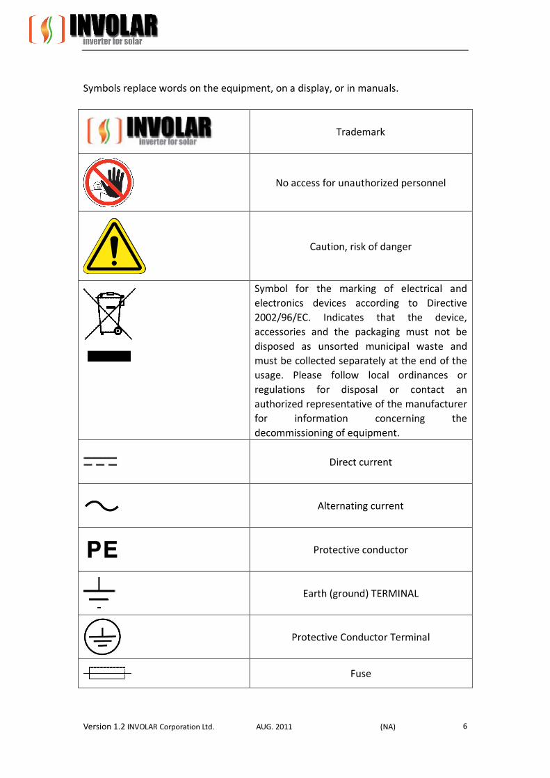
Symbols replace words on the equipment, on a display, or in manuals.
Trademark
No access for unauthorized personnel
Caution, risk of danger
Symbol for the marking of electrical and electronics devices according to Directive 2002/96/EC. Indicates that the device, accessories and the packaging must not be disposed as unsorted municipal waste and must be collected separately at the end of the usage. Please follow local ordinances or regulations for disposal or contact an authorized representative of the manufacturer for information concerning the decommissioning of equipment.
Direct current
Alternating current
Protective conductor
Earth (ground) TERMINAL
Protective Conductor Terminal
Fuse
Version 1.2 INVOLAR Corporation Ltd. AUG. 2011 (NA) 7
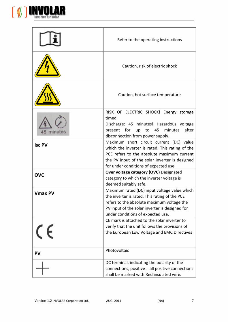
Refer to the operating instructions
Caution, risk of electric shock
Caution, hot surface temperature
RISK OF ELECTRIC SHOCK! Energy storage timed Discharge: 45 minutes! Hazardous voltage present for up to 45 minutes after disconnection from power supply.
Isc PV Maximum short circuit current (DC) value which the inverter is rated. This rating of the PCE refers to the absolute maximum current the PV input of the solar inverter is designed for under conditions of expected use.
OVC Over voltage category (OVC) Designated category to which the inverter voltage is deemed suitably safe.
Vmax PV Maximum rated (DC) input voltage value which the inverter is rated. This rating of the PCE refers to the absolute maximum voltage the PV input of the solar inverter is designed for under conditions of expected use.
CE mark is attached to the solar inverter to verify that the unit follows the provisions of the European Low Voltage and EMC Directives
PV Photovoltaic
DC terminal, indicating the polarity of the connections, positive,all positive connections shall be marked with Red insulated wire.

Version 1.2 INVOLAR Corporation Ltd. AUG. 2011 (NA) 8
DC terminal, indicating the polarity of the connections, negative, all negative connections shall be marked with black insulated wires.
PCS Power conversion equipment, hereby is our DC/AC inverter
Service Personnel A person having appropriate technical training and experience necessary to be aware of hazards to which that person may be exposed in performing a task and of measures to minimize the risks to that person or other persons
Qualified Competent Personnel Person adequately advised or supervised by an electrically skilled person to enable him or her to perceive risks and to avoid hazards which electricity can create. For the purpose of the safety information of this manual, a "qualified person" is someone who is familiar with requirements for safety, refrigeration system and EMC and is authorized to energize, ground, and tag equipment, systems, and circuits in accordance with established safety procedures. The Involar inverter system may only be commissioned and operated by competent personnel.
DVC Decisive voltage class Closed Electrical Operating Area Room or location for electrical equipment to which
access is restricted to skilled or instructed persons by the opening of a door or the removal of a barrier by the use of a key or tool and which is clearly marked by appropriate warning signs
Technical Competence The procedures described in this manual should be performed by trained competent personnel only. Maintenance should only be undertaken by competent individuals who have a general knowledge of and experience with devices of this nature. No repairs should ever be undertaken or attempted by anyone not having such competency.
Version 1.2 INVOLAR Corporation Ltd. AUG. 2011 (NA) 9
Compliance with safety regulations depends upon installing and configuring system correctly, including using the specified wirings. The system must be installed only by professional assemblers who are familiar with requirements for safety, Photovoltaic system and EMC. The assembler is responsible for ensuring that the end system complies with all the relevant laws in the country where it is to be used. Involar requires using only genuine replacement parts, manufactured or sold by Involar. Read completely through each step in every procedure before starting the procedure; any exceptions may result in a failure to properly and safely complete the attempted procedure. The individual sub-assembly of the system shall be interconnected by means of the wiring methods outlined in national/international regulations but not limited to the BS7671 Requirements/ VDE regulation 0107. All electrical installations must be made in accordance with the National Electrical regulations, and any other codes and regulations applicable to the installation site. Servicing of this product in accordance with this manual should never be undertaken in the absence of proper tools, test equipment and the most recent revision to this manual which is clearly and thoroughly understood.
3 Safety Instructions and EC Directives
This chapter contains the safety instructions which you must follow when installing, operating and servicing the unit. If ignored, physical injury or death may follow, or damage may occur to the unit. Read the safety instructions before you commence work on the unit. If you are unable to understand the Dangers, Warnings, Cautions or Instructions, contact the manufacturer or an authorized service dealer before installing, operating and servicing the unit. For INVOLAR Micro-Inverter Warranty Terms and Conditions, see the appendix of this manual.
SAVE THESE INSTRUCTIONS- This manual contains important instructions for the
MAC250 that shall be followed during installation and maintenance.
Be aware that only competent personnel should install and /or replace INVOLAR
Micro-Inverters.
Perform all electrical installations in accordance with all local electrical codes.
Compliance with the rules of correct use of tools and personal protective equipment
(PPE) ensuring a safe installation.
The inverter can still be charged with a hazardous voltage after being disconnected
from the supply. Allow a 45 minute discharge period before working on the inverter.
Be aware that only competent personnel should maintain INVOLAR Micro-Inverter.
Connect the INVOLAR Micro-Inverter to the electrical utility grid only after receiving prior
Version 1.2 INVOLAR Corporation Ltd. AUG. 2011 (NA) 10
approval from the utility company.
During the day time, use opaque covering on PV array to screen the sunshine before
installing the INVOLAR Micro-Inverter, thus eliminating the risk of electric shock to
persons working on the system.
The photovoltaic micro-inverter is not intended to be secured to the back of the
photovoltaic module. It should be secured to the framework supporting the PV module.
MAC250 is intended to be connected only to a dedicated branch circuit.
The device is not provided with ground-fault detector/interrupter unit.
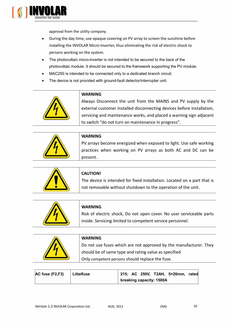
WARNING
Always Disconnect the unit from the MAINS and PV supply by the
external customer installed disconnecting devices before installation,
servicing and maintenance works, and placed a warning sign adjacent
to switch “do not turn on maintenance in progress”.
WARNING
PV arrays become energized when exposed to light. Use safe working
practices when working on PV arrays as both AC and DC can be
present.
CAUTION!
The device is intended for fixed installation. Located on a part that is
not removable without shutdown to the operation of the unit.
WARNING
Risk of electric shock, Do not open cover. No user serviceable parts
inside. Servicing limited to competent service personnel.
WARNING
Do not use fuses which are not approved by the manufacturer. They
should be of same type and rating value as specified
Only competent persons should replace the fuse.
AC fuse (F2,F3) Littelfuse 215; AC 250V, T2AH, 5×20mm, rated breaking capacity: 1500A

Version 1.2 INVOLAR Corporation Ltd. AUG. 2011 (NA) 11
WARNING
Risk of electric shock – Both A.C. and D.C. voltage sources are
terminated inside this device. Each circuit must be individually
disconnected before servicing.
WARNING Hot surfaces – To reduce the risk of burns – Do not touch device surface when the device is running. Allow 30 minutes cooling down period after switch off before handling the device.
WARNING
Risk of electric shock from energy stored in capacitor! Do not remove
cover until 45 minutes after disconnecting all sources of supply.
WARNING
The printed circuit boards contain components sensitive to
electrostatic discharge. Wear a grounding wrist band when handling
the boards. Do not touch the boards unnecessarily.
WARNING
Do not operate device if found to be damaged or lacking parts.
WARNING
Before installing the unit, obtain approval from the utility company.
WARNING
Ensure adequate spacing distances between the unit and other
equipment or structures. Ensure that air can pass freely around the
unit for heat dissipation and maintenance accessibility.
DANGER
This photovoltaic micro-inverter is only for use in a closed electrical operating area! The device shall not

Version 1.2 INVOLAR Corporation Ltd. AUG. 2011 (NA) 12
be energized during installation or maintenance!
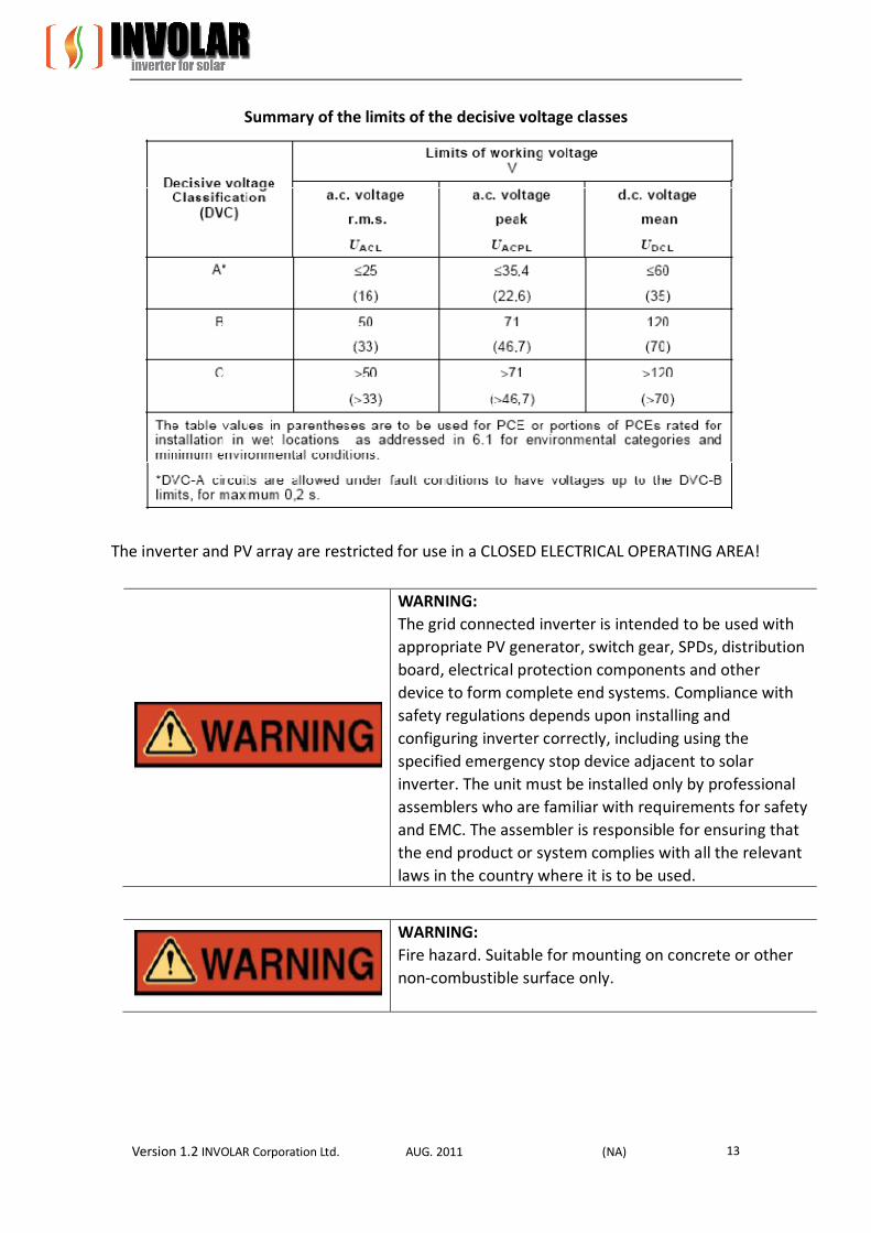
An internal isolation transformer is provided in the micro-inverter, internal transformer is galvanic isolation from the MAINS and PV array by reinforced insulation. PV input circuit is earthed, and non-earthed pole of PV input keeps basic insulation isolation from earthed metal. In accordance to EN 62109-1:2010, circuits complying with the requirements for DVC-A are considered safe to touch, however, since the device is intended for outdoor use and Vmax PV is rated 50V D.C, which exceeds maximum 35V DC limit for DVC-A in WET LOCATION as below:
Version 1.2 INVOLAR Corporation Ltd. AUG. 2011 (NA) 13
Summary of the limits of the decisive voltage classes
The inverter and PV array are restricted for use in a CLOSED ELECTRICAL OPERATING AREA!
WARNING: The grid connected inverter is intended to be used with appropriate PV generator, switch gear, SPDs, distribution board, electrical protection components and other device to form complete end systems. Compliance with safety regulations depends upon installing and configuring inverter correctly, including using the specified emergency stop device adjacent to solar inverter. The unit must be installed only by professional assemblers who are familiar with requirements for safety and EMC. The assembler is responsible for ensuring that the end product or system complies with all the relevant laws in the country where it is to be used.
WARNING: Fire hazard. Suitable for mounting on concrete or other non-combustible surface only.
Version 1.2 INVOLAR Corporation Ltd. AUG. 2011 (NA) 14
WARNING: Be aware that the input DC voltage of the INVOLAR Micro-Inverter shall not exceed 50V, higher voltage may cause permanent damage to the device; it contains no user serviceable and INVOLAR-Micro-Inverter Warranty parts.
WARNING: This unit is not provided with a GFDI device. The inverter must be fitted with an external device as required by the Article 690 of the National Electrical Code for the Installation location.
WARNING: The device is not provided with automatic disconnecting means – this device shall be provided with external relaying protection in accordance with local codes and local utility requirements.
CAUTION: SAVE THESE INSTRUCTIONS– This manual contains important instructions for Model MAC250 that shall be followed during installation and maintenance of the photovoltaic micro-inverter.
WARNING: To reduce the risk of fire, do not connect to an ac load centre (circuit breaker panel) having multi-wire branch circuits connected
CAUTION: To reduce the risk of fire, connect only to a circuit provided with 16 amperes maximum branch-circuit over current protection in accordance with local codes and local utility requirements.
CAUTION: Final circuit over current protection of the AC circuit shall be provided by others and should be suitable for system design.
Version 1.2 INVOLAR Corporation Ltd. AUG. 2011 (NA) 15
3.1 EC Directives This chapter follows the requirements of the European Low Voltage Directives, contains the safety instructions and conditions of acceptability for the endues system, which you must follow when installing, operating and servicing the unit. If ignored, physical injury or death may follow, or damage may occur to the unit. Read these instructions before you work on the unit. If you are unable to understand the Dangers, Warnings, Cautions or Instructions, contact the manufacturer or an authorized service dealer before installing, operating and servicing the unit. The Grid Connected Inverter meets the requirements stipulated in Low Voltage Directive (LVD) 2006/95/EC and Electromagnetic Compatibility (EMC) Directive 2004/108/EC. The unit is tested based on: EN 62109-1:2010; EN 61000-6-1; EN61000-6-2; EN61000-6-3; G83-1; EN50438; VDE0126-1-1:2006. When installing the PV system, start up of the unit (i.e. start of designated operation) is prohibited until it is determined that the full system meets the requirements stipulated in the EC Directive (2006/95/EC, 2004/108/EC etc). The grid connected Inverter leaves the factory completely connecting device and ready for connection to the mains and PV supply. The unit shall be installed in accordance with national wiring regulations. Compliance with safety regulations depends upon installing and configuring system correctly, including using the specified wirings. The system must be installed only by competent assemblers who are familiar with requirements for safety and EMC. The assembler is responsible for ensuring that the end system complies with all the relevant laws in the country where it is to be used. The individual subassembly of the system shall be interconnected by means of the wiring methods outlined in national/international regulations but not limited to the BS7671 Requirements/ VDE regulation 0107.
WARNINGS The device is not provided with ground-fault detector/interrupter unit.
WARNINGS The device is not provided with automatic disconnecting means – this device shall be provided with external relaying protection in accordance with local codes and local utility requirements.
[Use Condition]

Version 1.2 INVOLAR Corporation Ltd. AUG. 2011 (NA) 16
1. Over voltage category: over voltage category III for MAINS connection, over voltage category II for PV supply according to IEC/EN 60664-1. 2. Pollution degree: Pollution degree III, not intended for heavy pollution of the air by dust, smoke, corrosive or radioactive particles, vapors or salt. 3. Class of protection: I. 4. Protection against ingress of water: IP65
WARNINGS The Degree of protection rating IP65 to IEC 60529 is applicable to the device when the supplied installation connectors are inserted correctly, and suitable external cord was fitted. If the unit is not connected in this way, hazardous live parts may be exposed and the IP Rating of the unit will be invalid
5. The equipment is rated to operate at an altitude less than 2000 m. 6. Installation: Equipment not suitable for use in the presence of explosive gases. Equipment not suitable for use in the presence of flammable gases or liquids. Not suitable for use in the presence of Exposure to strong electric or magnetic fields Not suitable for use in the presence of Exposure to heavy vibration and shocks Not suitable for use by untrained personnel. 7. The unit is suitable for connection to a MAINS circuit capable of delivering not more than 160 rms symmetrical Amperes. The absolute maximum total PV array short circuit current (D.C.) that the inverter is rated to have connected to its PV input, under worst-case conditions of ambient temperature, irradiance, shall be less than 12A. 8. Supply earthing systems and system voltage: TN-C-S, 120/240V (L to N/ L to L) 9. PV modules for non-isolated inverters: PV modules shall have an IEC 61730 Class A rating, PV modules must have a maximum system voltage rating based upon the AC mains voltage. [Surge Protective Devices (SPDs) for PV installation]
Over-voltage protection with surge arresters should be provided when the PV power system is installed. The grid connected inverter is not fitted with SPDs in both PV input side and MAINS side.

Version 1.2 INVOLAR Corporation Ltd. AUG. 2011 (NA) 17
Lightning can cause damage either from a direct strike or from surges due to a nearby strike. Induced surges are the more likely cause of lightning damage in the majority of installations, especially in rural areas where electricity supplies are usually by long overhead lines. Surges may be induced on both the PV array conductors and the A.C. cables leading to the building. Specialists in lightning protection should be consulted during the endues application. Using appropriate external lightning protection, the effect of a direct lightning strike into a building can be mitigated in a controlled way, and the lightning current can be discharged into the ground.
Installation of SPDs to protect the inverter against mechanical damage and excessive stress include a surge arrester in case of a building with external lightning protection system (LPS) when separation distance s is kept: To protect the D.C. system, surge suppression devices (SPD Type 2) should be fitted at the inverter end of the D.C. cabling and at the array, located between the inverter and the PV generator, if the voltage protection level (VP) of the surge arresters is greater than 1100 V, an additional SPD Type 3 required for surge protection for electrical devices.
To protect the A.C. system, surge suppression devices (SPD, type 2) should be fitted at the main incoming point of A.C. supply (at the consumer’s cut-out), located between the inverter and the meter/distribution system; SPD (test impulse D1) for signal line according to EN 61643-21 All D.C. cables should be installed to provide as short run as possible, positive and negative cables of the same string or main DC supply should be bundled together, avoiding the creation of loops in the system. This requirement for short runs and bundling includes any associated earth/bonding conductors.
Spark gap devices are not suitable for use in DC circuits as once conducting, they won’t stop conducting until the voltage across their terminals is typically less than 30 volts.

Version 1.2 INVOLAR Corporation Ltd. AUG. 2011 (NA) 18
[Selection of fuse and cables]
Mains cable (AC line cable) shall be short circuit protected and thermal overload protected. Always fit the input cable with fuses. Normal gG (US: CC or T) fuses will protect the input cable in short circuit situations. They will also prevent damage to adjoining equipment. Dimension the fuses according to local safety regulations, appropriate input voltage and the rated current of the solar inverter. AC output protected by external fuse (gG, rated current 16 A/ 250 VAC), provided in all live connections to the AC supply. The rated short circuit breaking capacity of the above protective device shall be at least equal to the prospective fault current at the point of installation. See section technical data of this manual for details. AC output cables: Cu, (L,N+PE, 2x2,5+2,5mm2 with a max length of 2m and operating time of the fuse is less than 5 seconds, installation method B2 according to EN 60204-1: 2006, annex D: cable in conduit cable trucking system, number of loaded circuit only one. Use 90 °C wire for ambient temperature between 40 °C and 65 °C.
NOTE For conditions differing from those mentioned above, dimension the cables according to local safety regulations, appropriate input voltage and the load current of the unit. (You can choose a thicker cable but the fuses must be rated according to the table.)
NOTE Fuses must be approved by notified body. Inverter is provided galvanic isolation from the MAINS to the PV array, back feed current to the array is not considered. However, DC side current is about 20,4A and decrease to 0A within 20.4ms under the PV input short circuit condition. Therefore, the current-carrying capacity of the components and sub-assemblies provided in the end-use system (connectors, cables, junction box, switchgear, etc.) and the reverse current PV module shall be considered based on back feed current and reverse current. The direct current (DC) circuit breaker or fuse between each solar generator and inverter shall be provided based on solar inverter input ratings. Select DC cables based on the above inverter back feed current and Isc PV rating and Vmax ratings.
Version 1.2 INVOLAR Corporation Ltd. AUG. 2011 (NA) 19
[Isolation Device]
The inverter is not provided with isolation device. However, as a complete assembly or system, the unit requires that the customer shall supply external fuses and isolation device. This is not only good practice based on safety consideration, but is a mandatory requirement as a license condition of an approved equipment. A manual AC switch disconnector and DC switch disconnector must be provided located in an accessible position. Please check the unit nameplate and run ample capacity. A suitably rated Isolating Switch (this is also an option that could be selected) should be fitted immediately adjacent to each unit and installed both for AC output and DC input. All incoming phase lines and neutral conductors and PV generator cables are to be suitably fused at the Sub-Board to protect the installed wiring and the unit. During installation, care should be taken to ensure that: –An appropriate approved disconnect device shall be provided as part of PV system; installation which shall disconnect simultaneously all live conductors of mains supply. –An appropriate approved disconnect device shall be provided as part of the device; installation which shall disconnect simultaneously all PV input conductors of PV generator. – The disconnect devices are positioned in close proximity to the equipment and is easily accessible to the operator. – It is clearly marked as a disconnect device for the solar inverter unit. Therefore, install separately a hand operated input disconnecting device (means) between the PV generator and inverter, between MAINS and inverter. The disconnecting devices must be of a type that can be locked to the open position during installation and maintenance work, and constructed to disconnect all live conductors of its power supply circuit. Place a warning sign “do not turn on – maintenance in progress” on the external disconnecting switch when it is shut down, and make sure that on/off remote controls are inhibited. Dual supply labelling should be provided at the service termination, meter position and all points of isolation to indicate the presence of onsite generation and indicating the position of the main A.C. switch disconnector.
Version 1.2 INVOLAR Corporation Ltd. AUG. 2011 (NA) 20
[Emergency Stop Devices]
For safety reasons, install the emergency stop devices at station adjacent to solar inverter combiner in the end system. The emergency stop of the unit can be enabled using the service switch as required in section [Isolation device] if this isolation device is installed adjacent to solar inverter. [PE Connection and Leakage Current]
The endues application shall monitoring of the protective conductor by a residual current operated protective device (RCD) with rated fault current Ifn ≤30mA which automatically disconnects the device in the case of a fault.
WARNINGS EARTH CONNECTION ESSENTIAL BEFORE CONNECTING SUPPLY Incorrect grounding can cause physical injury, death or equipment malfunction and increase electromagnetic interference. Make sure that grounding conductors are adequately sized as required by safety regulations. Do not connect the ground terminals of the unit in series in case of a multiple installation.
WARNINGS This product can cause current with an A.C. component. Where a residual current operated protective (RCD) or monitoring (RCM) device is used for protection in case of direct or indirect contact, only an RCD or RCM of Type B is allowed on the supply side of this product.
[Safety Check] The following safety checks should be performed at least every 12 months by manufacturer’s qualified person who has adequate training, knowledge, and practical experience to perform these tests. The data should be recorded in an equipment log. If the device is not functioning properly or fails any of tests, the device has to be repaired.

Version 1.2 INVOLAR Corporation Ltd. AUG. 2011 (NA) 21
1. Inspect the equipment and accessories for mechanical and functional damage. 2. Inspect the safety relevant labels for legibility. 3. Inspect the fuse to verify compliance with rated current and breaking characteristics. 4. Verify that the device functions properly as described in the instructions for use. 5. Verify that the current/voltage sensors functions properly. 6. Verify software or firmware that performs safety critical application functions properly. 7. Check earth connection, retightening of terminals 8. Check the following safety parameters which are factory set and fixed per IEC 62116:2008 and IEC 61727:2004, this trip point is factory set and fixed, user cannot change this parameter. Exceeding this limit will trigger de-energized-to-trip system and alarm within time as specified in the following tables.
WARNING! The device is not provided with ground-fault detector/interrupter unit.

Version 1.2 INVOLAR Corporation Ltd. AUG. 2011 (NA) 22
WARNING! The device is not provided with automatic disconnecting means – this device shall be provided with external relaying protection in accordance with local codes and local utility requirements.
9. Measurement of insulation resistance, consult manufacturer. 10. Measurement of earth resistance, consult manufacturer. 11. Mounting structures: Verify tightness and integrity of bolts and other fastening devices; Verify if there is significant corrosion 12. Using manufacturer’s procedures and/or technical data on an “as-needed” basis when performing periodic component calibrations. Consult manufacturer for safety check procedure.
[Interface Protection and Inverter Set Points]
WARNING! The device is not provided with ground-fault detector/interrupter unit.
WARNING! The device is not provided with automatic disconnecting means – this device shall be provided with external relaying protection in accordance with local codes and local utility requirements.
Incorporated interface protection is designed according to IEC 61727:2004 and IEC 62116:2008, it is insensitive to normal voltage and frequency variations in the distribution network. The interface protection ensures that the inverter cease to energize the distribution network when any parameters listed as below exceeds the applied operating setting. Disconnection is provided in case of any hardware malfunctioning. The solar inverter will cease to energize the network in response to an interface protection; however, this is not achieved by disconnecting means between inverter and grid.

Version 1.2 INVOLAR Corporation Ltd. AUG. 2011 (NA) 23
Default interface protection settings
WARNINGS Alteration of the above settings or full setting range of the interface protection may cause a breach of the type-certificate marking. Unauthorized access to factory safety parameters setting and software should be prohibited.
A reset to the factory safety parameters requires retesting and verification in conjunction with the end-use system.

Version 1.2 INVOLAR Corporation Ltd. AUG. 2011 (NA) 24
4 The INVOLAR Micro-Inverter System Instruction
4.1 The INVOLAR Micro-Inverter System The three key elements of an INVOLAR Micro-Inverter System are: The INVOLAR Micro-Inverter The INVOLAR ETU communication gateway The INVOLAR SDEDAS web-based monitoring and analysis PV module The INVOLAR Micro-Inverter maximizes energy production from the PV array. Each INVOLAR Micro-Inverter is individually connected to one PV module in the array. (See Figure 4-1). This unique configuration means that a Maximum Peak Power Point Tracker (MPPT) controls each PV module. The INVOLAR Micro-Inverter ensures top performance for its associated PV module although individual PV modules in the array may be affected by shading, soiling, orientation, or PV module aging. This insures that the maximum power available from each PV module with a consequent up to 25% more energy production. The distributed nature of the INVOLAR Micro-Inverter System insures that there is no single point of system failure in the PV system.
EnergyTerminal
Unit
LCF
SEDAS-Internetserver
Broadbandrouter
L N PE
MAC250 MAC250
MAC250
Grid
Local PC
Meter
P V P V
P V P V
MAC250
Customer web terminal
Figure4-1 The INVOLAR Micro-Inverter System
NOTE The INVOLAR ETU (Energy Terminal Unit) communication gateway, the INVOLAR LCF(Line Communication Filter) ,and the INVOLAR SEDAS(Solar Energy Data Acquisition System) are optional elements, before installing these elements, read all instruction and cautionary marking in the related user manual.

Version 1.2 INVOLAR Corporation Ltd. AUG. 2011 (NA) 25
4.2 The INVOLAR MAC250 Micro-Inverter By adopting high frequency DC link topology (Figure 4-2) and dual –DSP controller, the Involar
MAC250 achieves precise variable frequency control for soft-switching during full load range. So that the MAC250 exhibit slow profile and high efficiency. Additionally, MAC250 shows high reliability, high power factor and low total harmonic distortion. The INVOLAR MAC250
Micro-Inverter realize the system expansion by simple parallel operation (maximum 16 PV
modules per branch)
PVinC oC
oL
Gv
HFDC/DC
i voo
Figure 4-2 the INVOLAR MAC250 Micro-Inverter Operation Principle
4.3 Features Advantages
Easy installation Without parameter configuration High level system reliability Low PV system noise Remote web-based monitoring and analysis System maximize energy harvest
Performance
High efficiency High power factor Soft start Low current harmonic Low DC injection
Protection Function Over voltage and under voltage protection Over frequency and under frequency protection Over current protection Input polarity reverse protection Short circuit protection Over temperature protection Anti-Island Anti-abnormal discharge protection Recovery of grid-connected protection

Version 1.2 INVOLAR Corporation Ltd. AUG. 2011 (NA) 26
5 INVOLAR Micro-Inverter Installation
WARNINGS: In case of installation in PV system, start up of the unit (i.e. start of designated operation) is prohibited until it is determined that the full system meets the requirements stipulated in the EC Directive (2006/95/EC, 2004/108/EC etc.). The grid-Connected Inverter leaves the factory completely connecting device and ready for connection to the mains and PV supply. The unit shall be installed in accordance with national wiring regulations. Compliance with safety regulations depends upon installing and configuring system correctly, including using the specified wirings. The system must be installed only by professional assemblers who are familiar with requirements for safety and EMC. The assembler is responsible for ensuring that the end system complies with all the relevant laws in the country where it is to be used. The individual subassembly of the system shall be interconnected by means of the wiring methods outlined in national/international regulations but not limited to the BS7671 Requirements/ VDE regulation 0107. To ensure the safe operation of the devices, they may be installed and commissioned only by qualified personnel in full compliance with the warnings referred to in this manual. Open the package and pick the product, check that if there is any distortion or impaired during transportation, meanwhile, check that if all the relating accessories and materials are here, you can see the accessories list in the “Appendix”. The instruction manual is an integral part of the unit and should therefore be read and kept carefully. It is recommended that the packaging should not be removed until the unit is located in the installation site. Do not dispose of packaging materials in the environment or leave them within reach of children as they may represent a hazard Check that there are no signs of damage. Before attempting installation and operation, check the information on the type designation label of the unit to verify that the unit is of the correct type. The label includes an IEC rating and CE markings, a type code and a serial number, which allow individual recognition of each unit. Check the mechanical and electrical installation of the unit before startup. Go through the checklist below together with another person. Read the sections “Safety instruction and EC Directives” and “Interface protection and Inverter set points’ on the previous pages of this manual before you work on the unit.
Version 1.2 INVOLAR Corporation Ltd. AUG. 2011 (NA) 27
Use a solid hard wall or metal structure. Before installing the unit, agree with the customer the site. Do not allow foreign object into the unit. The rating plate and warning marking must be readable after installation. Install the unit clear of any obstructions. The enclosure must never be covered. The equipment is classed as one not accessible to the general public. A suitable guarding which is keep min. 1.5mm distance around the perimeter of the device is mandatory to prevent against access to general public, especially for children or infirm persons when the device is located in an unprotected area. Make sure that dust from drilling does not enter the unit when installing. Do not place flammable materials near the unit. Failure to observe this warning may result in a fire. The solar inverter shall be installed so that the inverter couplers shall be easily accessible and located between 0.6m and 1.9m above the servicing level. An upper limit of 1.7m is recommended. -easy access to the electrical power connection point; -accessibility for maintenance and repair work;
Parts serving for support or immobilization of unit shall be designed and manufactured so as to minimize the RISK of physical injuries and of accidental loosening of fixings. Loading capacity and hardness of the supporting surface, Load rating of mounting bracket should be at least four times the weight of the devices according to EN 62109-1, and supporting characteristics will be impaired by wear, corrosion, material fatigue or ageing. This shall be calculated by inspection of the design data of supporting material and consulting construction engineer.
Version 1.2 INVOLAR Corporation Ltd. AUG. 2011 (NA) 28
5.1 INVOLAR MAC250 Micro-Inverter operational environment Temperature INVOLAR MAC250 Micro-Inverter full power operation ambient temperature: -40°C~﹢65°C,above 25°C , the inverter output power drops at the same temperature coefficient as the PV module’s, i.e., 0.44% per degree Celsius. Humidity Air humidity≤90%。 Storage If the INVOLAR MAC250 Micro-Inverter had been stored for 2 years, the inverter may need to be energised before being installed. Please contact INVOLAR for more information.
5.2 INVOLAR MAC250 Micro-Inverter operational condition in PV System PV Module The max PV Module open circuit voltage is no more than 50V. The range of PV Module output power is 180W-250W. Connection to the electrical utility grid Connect the INVOLAR Micro-Inverter to the electrical utility grid only after receiving prior approval from the utility company. It should match the on-grid conditions:
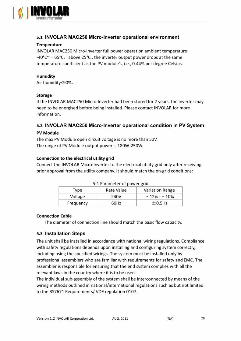
5-1 Parameter of power grid Type Rate Value Variation Range
Voltage 240V ﹣12% -﹢10% Frequency 60Hz ±0.5Hz
Connection Cable The diameter of connection line should match the basic flow capacity.
5.3 Installation Steps The unit shall be installed in accordance with national wiring regulations. Compliance with safety regulations depends upon installing and configuring system correctly, including using the specified wirings. The system must be installed only by professional assemblers who are familiar with requirements for safety and EMC. The assembler is responsible for ensuring that the end system complies with all the relevant laws in the country where it is to be used. The individual sub-assembly of the system shall be interconnected by means of the wiring methods outlined in national/international regulations such as but not limited to the BS7671 Requirements/ VDE regulation 0107.

Version 1.2 INVOLAR Corporation Ltd. AUG. 2011 (NA) 29
Power to the unit must be turned on only after installation work has been completed. All electrical connections must be carried out by qualified personnel in accordance with legislation in force in the country concerned.
Before connecting, disconnect the connection between solar generator and inverter and locked it
to the open position during installation. Place a warning sign “do not turn on – maintenance in
progress” on the external disconnecting switch when it is shut down, and make sure that on-off
remote controls are inhibited. Refer to this manual, section 3.Safety instruction and EC Directives
– isolation device.
The open-circuit voltage of PV generator under worst case conditions of ambient temperature, irradiance, etc. shall not exceed 50V, failure to observe this, it may cause electric shock hazards or completely damage of the inverter.
WARNINGS HIGH LEAKAGE CURRENT, EARTH CONNECTION ESSENTIAL BEFORE CONNECTING SUPPLY.
For the cables connected to PV inverter and Grid, choose the appropriate wires according to the capacity of the inverter and PV components. Calculate the max. input current and max. output current of the inverter according to the actually
system , inverter rating label and TECHNICAL PARAMETER. For details, refer to this manual, Section 3 Safety instruction and EC Directives, [Selection of fuse and cables].
Version 1.2 INVOLAR Corporation Ltd. AUG. 2011 (NA) 30
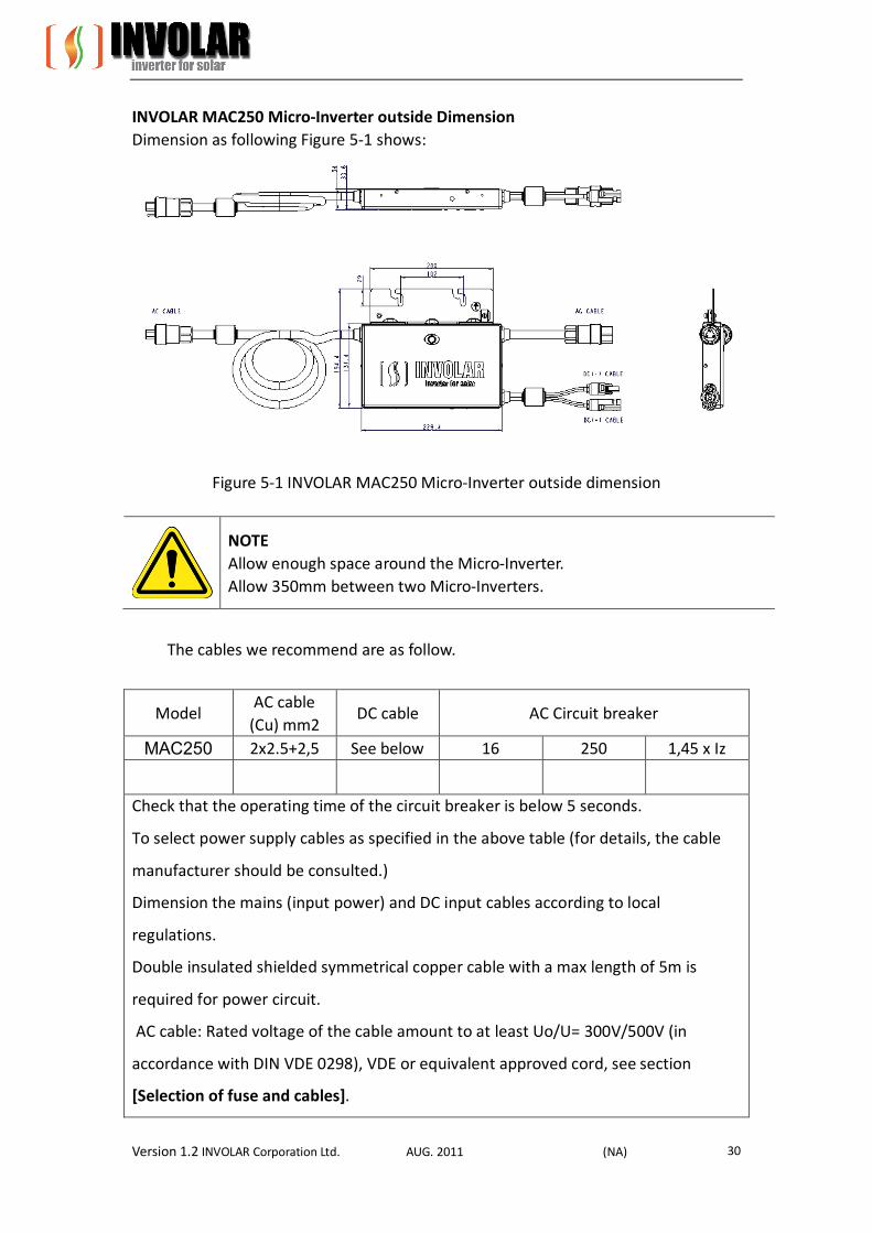
INVOLAR MAC250 Micro-Inverter outside Dimension Dimension as following Figure 5-1 shows:
Figure 5-1 INVOLAR MAC250 Micro-Inverter outside dimension
NOTE Allow enough space around the Micro-Inverter. Allow 350mm between two Micro-Inverters.
The cables we recommend are as follow.
Model AC cable
(Cu) mm2 DC cable AC Circuit breaker
MAC250 2x2.5+2,5 See below 16 250 1,45 x Iz
Check that the operating time of the circuit breaker is below 5 seconds.
To select power supply cables as specified in the above table (for details, the cable
manufacturer should be consulted.)
Dimension the mains (input power) and DC input cables according to local
regulations.
Double insulated shielded symmetrical copper cable with a max length of 5m is
required for power circuit.
AC cable: Rated voltage of the cable amount to at least Uo/U= 300V/500V (in
accordance with DIN VDE 0298), VDE or equivalent approved cord, see section
[Selection of fuse and cables].
Version 1.2 INVOLAR Corporation Ltd. AUG. 2011 (NA) 31
DC cable: Code designation: PV1F;
Rated voltage AC U0/U 0, 6/1 kV; ambient temperature: –40 °C to +90 °C; Max.
conductor temperature: 120 °C; TUV or equivalent approved recommended.
All positive connections shall be made with Red insulated wire, and all negative connections with Black insulated wires.
To guarantee the degree of protection IP65, the installation connector and connector shall be used based on its manual.
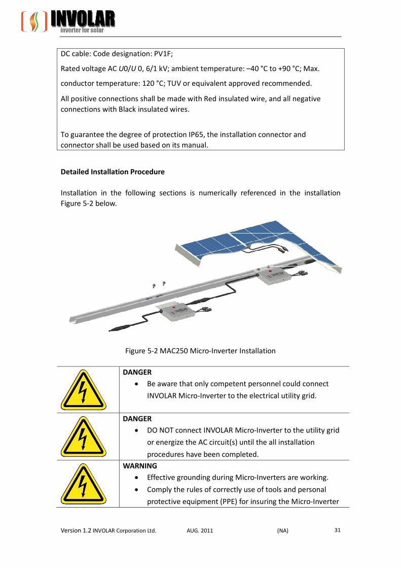
Detailed Installation Procedure Installation in the following sections is numerically referenced in the installation Figure 5-2 below.
Figure 5-2 MAC250 Micro-Inverter Installation
DANGER Be aware that only competent personnel could connect
INVOLAR Micro-Inverter to the electrical utility grid.
DANGER DO NOT connect INVOLAR Micro-Inverter to the utility grid
or energize the AC circuit(s) until the all installation
procedures have been completed.
WARNING Effective grounding during Micro-Inverters are working.
Comply the rules of correctly use of tools and personal
protective equipment (PPE) for insuring the Micro-Inverter
Version 1.2 INVOLAR Corporation Ltd. AUG. 2011 (NA) 32
safe running.
CAUTION Inverter DC input power cable and the output cables must be isolated from each other, and do not put them in the same cable tray or cable rack.
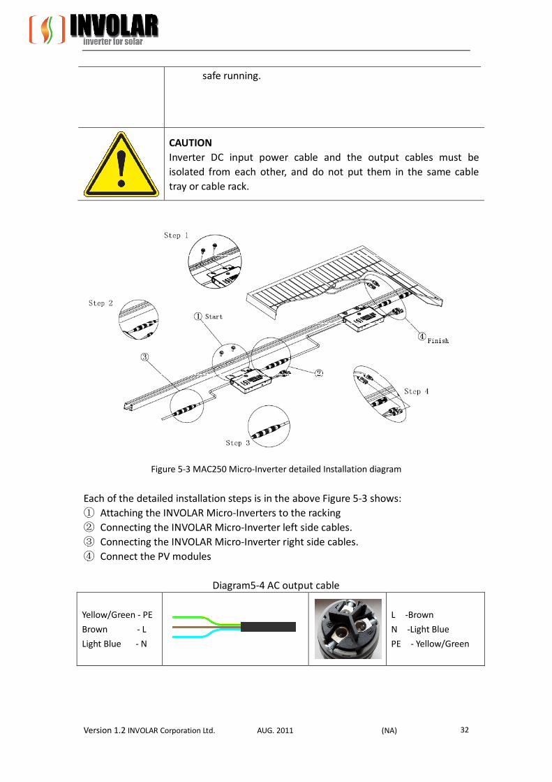
Figure 5-3 MAC250 Micro-Inverter detailed Installation diagram
Each of the detailed installation steps is in the above Figure 5-3 shows: ① Attaching the INVOLAR Micro-Inverters to the racking ② Connecting the INVOLAR Micro-Inverter left side cables. ③ Connecting the INVOLAR Micro-Inverter right side cables. ④ Connect the PV modules
Diagram5-4 AC output cable
Yellow/Green - PE
Brown - L
Light Blue - N
L -Brown
N -Light Blue
PE - Yellow/Green
Version 1.2 INVOLAR Corporation Ltd. AUG. 2011 (NA) 33
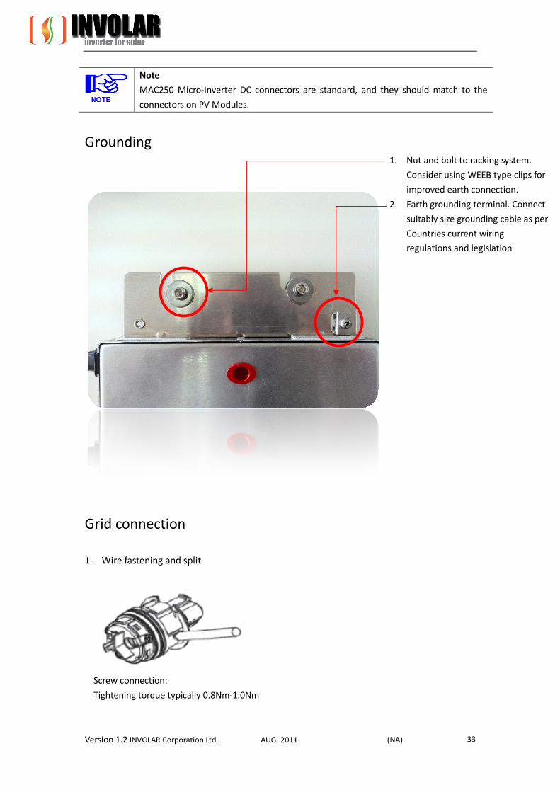
Note
MAC250 Micro-Inverter DC connectors are standard, and they should match to the
connectors on PV Modules.
Grounding
Grid connection
1. Wire fastening and split
Screw connection:
Tightening torque typically 0.8Nm-1.0Nm
1. Nut and bolt to racking system.
Consider using WEEB type clips for
improved earth connection.
2. Earth grounding terminal. Connect
suitably size grounding cable as per
Countries current wiring
regulations and legislation
Version 1.2 INVOLAR Corporation Ltd. AUG. 2011 (NA) 34
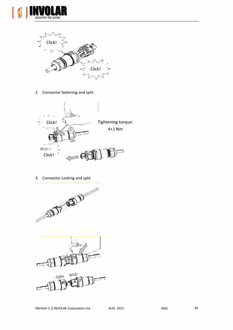
2. Connector fastening and split
3. Connector Locking and split
Tightening torque:
4+1 Nm
Click!
Click!
Click!
Click!
Version 1.2 INVOLAR Corporation Ltd. AUG. 2011 (NA) 35
6. Function Instructions
6.1 Working Mode The working modes of an INVOLAR Micro-Inverter are: Start-up Active Fault Standby The detailed working mode descriptions are as below:
Start-up Start-up mode is for a newly installed INVOLAR Micro-Inverter. This start-up mode must base on the proper AC and DC cables connecting and whole PV system grounding. Active When the Micro-Inverter is in normal operation process, this insures that the power available from each PV module is exported to the utility grid. Fault If the PV system does not operate correctly, INVOLAR Micro-Inverter would stop automatically and enter into Disable mode. The INVOLAR Micro-Inverter system keeps detecting the disable information. The INVOLAR Micro-Inverter is in disable mode until fault release. If the inoperative Micro-Inverter has been repaired and match to the electrical utility grid, the whole INVOLAR Micro-Inverter system would enter operation mode after 20 seconds to 5 minutes. Be aware that only qualified personnel should maintain the INOVLAR Micro-Inverters. Standby When the Micro-Inverter is in operation process but keeps with low voltage and current in AC side for a certain time. The Micro-Inverter manages transition from “Active” to “Standby”. In “standby” mode, Micro- Inverters keep detecting the energy output of PV Modules. When the output energy reaches the power generation conditions, the inverter would enter into “Active” from the “Standby” state.
CAUTION INVOLAR Micro-Inverter cannot enter into “Standby” or “Active” mode when the PV modules are insufficient in the conditions of night and rainy day.

Version 1.2 INVOLAR Corporation Ltd. AUG. 2011 (NA) 36
6.2 Grid Connection INVOLAR MAC250 Micro-Inverter system connects grid automatically. It detects and monitors the performance of each PV module in your PV array. When the output energy reaches the power generation conditions, the INVOLAR MAC250 Micro-Inverter system begin connect grid and generate electricity.
In the process of connecting grid and generating electricity, a Maximum Peak Power Point Tracker (MPPT) controls each PV module by INVOLAR Micro-Inverter system.
6.3 Grid Disconnect If the state grid cannot match the following situations (diagram 6-1), it bring the
INVOLAR Micro-Inter to a rest.
Diagram (6-3) Parameter of European state power grid Type Rated Variation Range
Voltage 240V 211V - 264V Frequency 60Hz 59.3Hz - 60.5Hz
Only to be carried out by qualified competent personnel.
Start inverter after checking all below steps:
WARNING Connect the INVOLAR Micro-Inverter to the electrical utility grid only after
receiving prior approval from the utility company.
WARNING Only competent qualified personnel should connect INVOLAR
Micro-Inverter to the electrical utility grid.
Installation checklist
To ensure the safe operation of the devices, they may be installed and commissioned only by qualified personnel in full compliance with the warnings referred to in this manual. Checklist Check the mechanical and electrical installation of the unit before start up. Go through the checklist below together with another person. Read the Safety instructions and EC directives on the previous pages of this manual before you work on the unit.
Version 1.2 INVOLAR Corporation Ltd. AUG. 2011 (NA) 37
Mechanical Installation Check screw connections on the inverter for tightness. The ambient operating conditions are allowed. (See Technical parameter); The unit is fixed properly on a non-flammable wall. (See Mechanical installation.) The cooling air will flow freely. The unit is fixed tightly and support is enough. (See Mechanical installation.) Electrical Installation Check polarity and voltage of the solar generator, make sure poles are correct and without reverse the poles of the connections! Check all screws of the connection terminals in the installation system before and after the inverter for tightness. The unit is grounded properly. The DC input voltage and AC output voltage matches the unit nominal voltage. Make sure that the solar generator cannot exceed the permissible input voltage range of the device The DC input and mains connections and their tightening torques are OK. Appropriate DC input and AC output fuses and disconnector are installed. The external cords and cables are fixed tightly, and strain relief clamp is provided for external accessible cords and cables。 Cord and cable inlets are sealed completely after cord/cable installation.
Start-Up Checks The device has been checked at the factory and adjusted so that it can be commissioned immediately after being installed. Following Section Installation checklist, for your personal safety and to avoid damage, the following safety checks should be performed before commencing by a competent qualified person who has adequate training, knowledge, and practical experience to perform these tests. The data should be recorded in an equipment log. If the device is not functioning properly or fails any of tests, the device has to be repaired. 1. Inspect the equipment and accessories for mechanical and functional damage. 2. Inspect the relevant safety labels for legibility. 3. Inspect the fuse to verify compliance with rated current and breaking characteristics. 4. Measurement of insulation resistance 5. Measurement of earth resistance 6. Mounting structures: Verify tightness and integrity of bolts and other fastening devices; Verify if there are any signs of corrosion.

Version 1.2 INVOLAR Corporation Ltd. AUG. 2011 (NA) 38
7 Disconnecting a Micro-Inverter from the PV Module
To ensure safe disconnection of the micro-inverter from the PV array, it must NOT
be carried out under load conditions. Ensure the following disconnection steps are
carried out in the order shown:
1. Cover the PV module (s) with an opaque cover.
2. Using a proved DC current test instrument, verify there is no current flowing in
the DC wires between the PV module and the micro-inverter.
3. Care should be taken when measuring DC currents, most clamp-on meters
must be zeroed first and tend to drift with time.
4. Isolate the AC branch circuit by isolating the circuit breaker.
5. Using a proved AC current test instrument, verify there is no current flowing in
the flowing into the branch circuit from the circuit breaker..
6. Disconnect the first AC connector in the branch circuit.
7. Using a proved DC current test instrument, AGAIN verify there is no current
flowing in the DC wires between the PV module and the micro-inverter.
8. Disconnect the PV module DC wire connectors from the micro-inverter.
9. Remove the micro-inverter from the PV array racking.

Version 1.2 INVOLAR Corporation Ltd. AUG. 2011 (NA) 39
8 Monitoring and Troubleshooting and Maintenance
No user-serviceable parts inside. Servicing should be carried out by a competent person who has adequate technical knowledge of the product. Never operate this product and change any part of inverter yourself. For servicing you should contact INVOLAR Corporation direct or an authorised distributor.
Safety checks Safety checks should be performed at least every 12 months by a competent person who has had adequate training, knowledge, and practical experience to perform these tests. The data should be recorded in an equipment log. If the device is not functioning properly or fails any of the tests, the device has to be repaired. For safety check details, refer to this manual, section 3 Safety instruction and EC Directives.
Maintain periodically Only competent qualified person may perform the following works. During the process of using the inverter, the competent person shall examine and maintain the device regularly. The required maintenance checks which should be carried out every 12 months are as follows: 1. Check the operation of the inverter. See that the LED is flashing in a healthy status. 2. Check the casing of the inverter for any signs of damage or corrosion. 3. Check the input and output cables for signs of corrosion, rodent damage or overheating. 4. Check the condition of he connector for signs of corrosion or overheating. 5. Check the PV modules for build up of debris or any heat spots.
Version 1.2 INVOLAR Corporation Ltd. AUG. 2011 (NA) 40
Before cleaning the inverter: Wear gloves and safety glasses. Isolate the DC supply to the inverter. Isolate the AC supply to the inverter. Wait for 45 minutes to ensure and positively charged components have
discharged. Clean the inverter casing with a damp cloth carefully. Check for any signs of corrosion or defects to the casing, cabling and cable
connector. Reinstall the inverter following the installation steps.
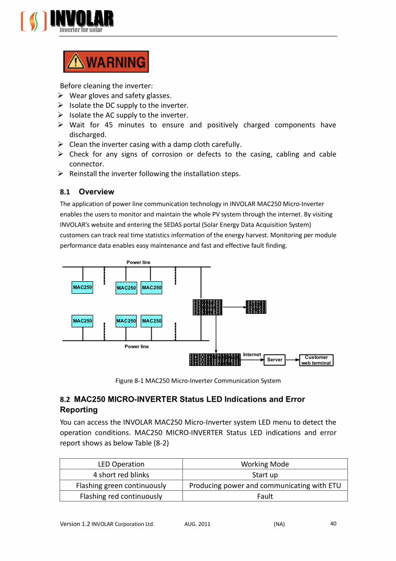
8.1 Overview The application of power line communication technology in INVOLAR MAC250 Micro-Inverter
enables the users to monitor and maintain the whole PV system through the internet. By visiting
INVOLAR’s website and entering the SEDAS portal (Solar Energy Data Acquisition System)
customers can track real time statistics information of the energy harvest. Monitoring per module
performance data enables easy maintenance and fast and effective fault finding.
Power line
MAC250 MAC250 MAC250
ServerBroadbandrouter
EnergyTerminal
Unit
Local PC
MAC250 MAC250 MAC250
Power line
Internet Customer web terminal
Figure 8-1 MAC250 Micro-Inverter Communication System
8.2 MAC250 MICRO-INVERTER Status LED Indications and Error Reporting You can access the INVOLAR MAC250 Micro-Inverter system LED menu to detect the operation conditions. MAC250 MICRO-INVERTER Status LED indications and error report shows as below Table (8-2)
LED Operation Working Mode
4 short red blinks Start up Flashing green continuously Producing power and communicating with ETU
Flashing red continuously Fault
Version 1.2 INVOLAR Corporation Ltd. AUG. 2011 (NA) 41
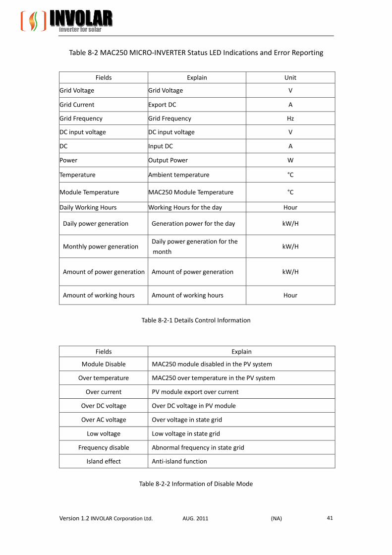
Table 8-2 MAC250 MICRO-INVERTER Status LED Indications and Error Reporting
Fields Explain Unit
Grid Voltage Grid Voltage V
Grid Current Export DC A
Grid Frequency Grid Frequency Hz
DC input voltage DC input voltage V
DC Input DC A
Power Output Power W
Temperature Ambient temperature °C
Module Temperature MAC250 Module Temperature °C
Daily Working Hours Working Hours for the day Hour
Daily power generation Generation power for the day kW/H
Monthly power generation Daily power generation for the
month kW/H
Amount of power generation Amount of power generation kW/H
Amount of working hours Amount of working hours Hour
Table 8-2-1 Details Control Information
Fields Explain
Module Disable MAC250 module disabled in the PV system
Over temperature MAC250 over temperature in the PV system
Over current PV module export over current
Over DC voltage Over DC voltage in PV module
Over AC voltage Over voltage in state grid
Low voltage Low voltage in state grid
Frequency disable Abnormal frequency in state grid
Island effect Anti-island function
Table 8-2-2 Information of Disable Mode
Version 1.2 INVOLAR Corporation Ltd. AUG. 2011 (NA) 42
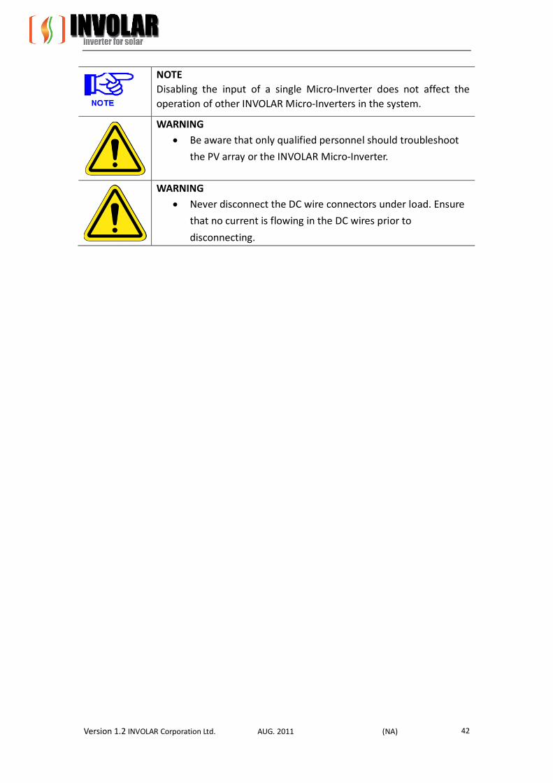
NOTE Disabling the input of a single Micro-Inverter does not affect the operation of other INVOLAR Micro-Inverters in the system.
WARNING Be aware that only qualified personnel should troubleshoot
the PV array or the INVOLAR Micro-Inverter.
WARNING Never disconnect the DC wire connectors under load. Ensure
that no current is flowing in the DC wires prior to
disconnecting.
Version 1.2 INVOLAR Corporation Ltd. AUG. 2011 (NA) 43
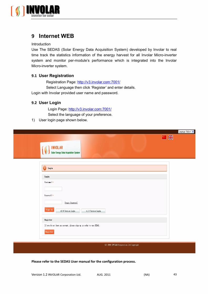
9 Internet WEB Introduction Use The SEDAS (Solar Energy Data Acquisition System) developed by Involar to real time track the statistics information of the energy harvest for all Involar Micro-inverter system and monitor per-module’s performance which is integrated into the Involar Micro-inverter system.
9.1 User Registration Registration Page: http://v3.involar.com:7001/ Select Language then click ‘Register’ and enter details.
Login with Involar provided user name and password.
9.2 User Login Login Page: http://v3.involar.com:7001/ Select the language of your preference.
1) User login page shown below.
Please refer to the SEDAS User manual for the configuration process.
Version 1.2 INVOLAR Corporation Ltd. AUG. 2011 (NA) 44
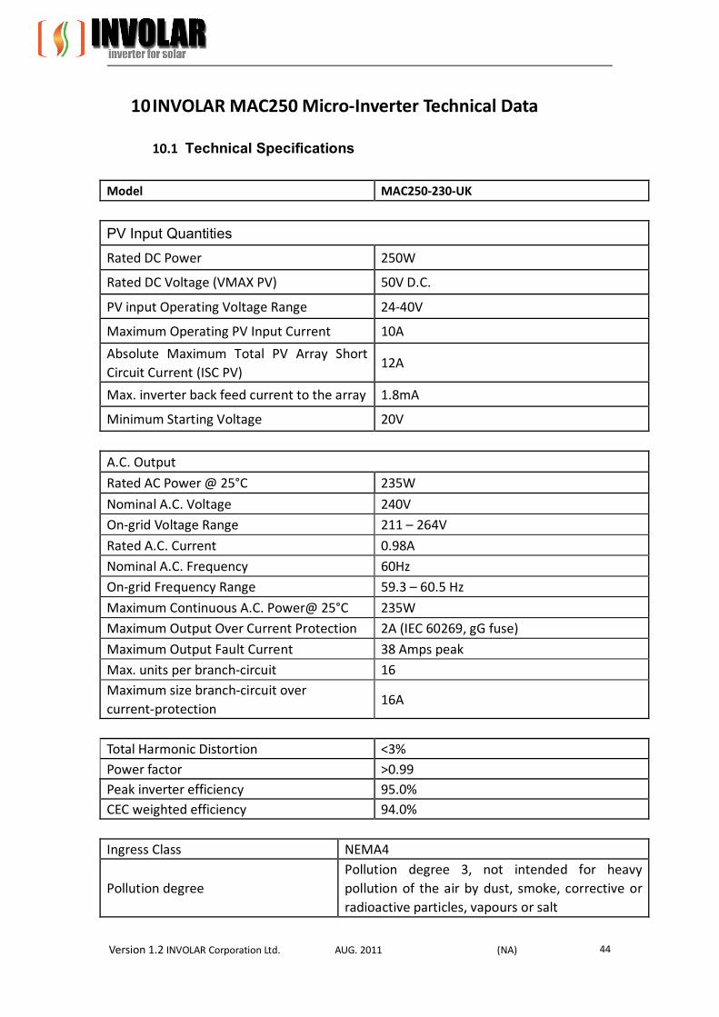
10 INVOLAR MAC250 Micro-Inverter Technical Data
10.1 Technical Specifications Model MAC250-230-UK
PV Input Quantities
Rated DC Power 250W
Rated DC Voltage (VMAX PV) 50V D.C.
PV input Operating Voltage Range 24-40V
Maximum Operating PV Input Current 10A
Absolute Maximum Total PV Array Short Circuit Current (ISC PV)
12A
Max. inverter back feed current to the array 1.8mA
Minimum Starting Voltage 20V
A.C. Output
Rated AC Power @ 25°C 235W
Nominal A.C. Voltage 240V On-grid Voltage Range 211 – 264V
Rated A.C. Current 0.98A Nominal A.C. Frequency 60Hz On-grid Frequency Range 59.3 – 60.5 Hz
Maximum Continuous A.C. Power@ 25°C 235W Maximum Output Over Current Protection 2A (IEC 60269, gG fuse)
Maximum Output Fault Current 38 Amps peak Max. units per branch-circuit 16 Maximum size branch-circuit over current-protection
16A
Total Harmonic Distortion <3% Power factor >0.99 Peak inverter efficiency 95.0% CEC weighted efficiency 94.0%
Ingress Class NEMA4
Pollution degree Pollution degree 3, not intended for heavy pollution of the air by dust, smoke, corrective or radioactive particles, vapours or salt
Version 1.2 INVOLAR Corporation Ltd. AUG. 2011 (NA) 45
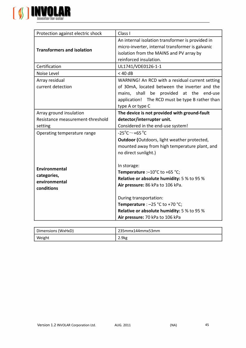
Protection against electric shock Class I
Transformers and isolation
An internal isolation transformer is provided in micro-inverter, internal transformer is galvanic isolation from the MAINS and PV array by reinforced insulation.
Certification UL1741/VDE0126-1-1 Noise Level < 40 dB Array residual current detection
WARNING! An RCD with a residual current setting of 30mA, located between the inverter and the mains, shall be provided at the end-use application! The RCD must be type B rather than type A or type C
Array ground insulation Resistance measurement-threshold setting
The device is not provided with ground-fault detector/interrupter unit. Considered in the end-use system!
Operating temperature range -25oC~+65 oC
Environmental categories, environmental conditions
Outdoor (Outdoors, light weather protected, mounted away from high temperature plant, and no direct sunlight.) In storage: Temperature :–10°C to +65 °C; Relative or absolute humidity: 5 % to 95 % Air pressure: 86 kPa to 106 kPa. During transportation: Temperature : –25 °C to +70 °C; Relative or absolute humidity: 5 % to 95 % Air pressure: 70 kPa to 106 kPa
Dimensions (WxHxD) 235mmx144mmx53mm
Weight 2.9kg

Version 1.2 INVOLAR Corporation Ltd. AUG. 2011 (NA) 46
11 Appendix
11.1 Limited Warranty INVOLAR provides a 15-year warranty (the exact time depends on the contract) due to our responsible attitude towards our customers, partners and our confidence in INVOLAR products. During the warranty period, if any defect in workmanship and materials of the INVOLAR micro-inverters is detected, customers are entitled to ask for replacement or repairing from INVOLAR with no extra cost. During the Warranty period, retain the product invoices and purchase date for free replacement or repairing. Proof of purchase will be required. The Limited Warranty does not cover the product which trademark is not visible. The Limited Warranty does not cover following situations:
Damaged by transportation
Improperly installed
Improperly operated
Improperly handled or used
Use under conditions for which the product was not designed or in an
unsuitable environment.
Any installation and use beyond the scope of relevant international standards
Damage cause by abnormal natural environment
The exact product dimensions and technical data depend on the latest released version, like has the change without prior notice.
Version 1.2 INVOLAR Corporation Ltd. AUG. 2011 (NA) 47
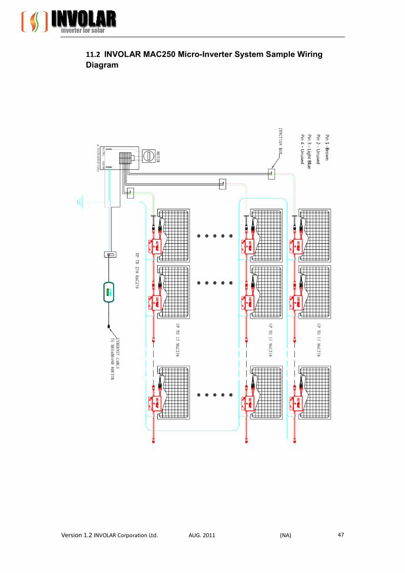
11.2 INVOLAR MAC250 Micro-Inverter System Sample Wiring Diagram
Version 1.2 INVOLAR Corporation Ltd. AUG. 2011 (NA) 48
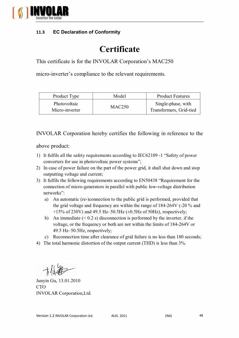
11.3 EC Declaration of Conformity
Certificate This certificate is for the INVOLAR Corporation’s MAC250
micro-inverter’s compliance to the relevant requirements.
Product Type Model Product Features Photovoltaic
Micro-inverter MAC250 Single-phase, with
Transformers, Grid-tied
INVOLAR Corporation hereby certifies the following in reference to the
above product:
1) It fulfils all the safety requirements according to IEC62109 -1 “Safety of power converters for use in photovoltaic power systems”;
2) In case of power failure on the part of the power grid, it shall shut down and stop outputting voltage and current;
3) It fulfils the following requirements according to EN50438 “Requirement for the connection of micro-generators in parallel with public low-voltage distribution networks”: a) An automatic (re-)connection to the public grid is performed, provided that
the grid voltage and frequency are within the range of 184-264V (-20 % and +15% of 230V) and 49.5 Hz–50.5Hz (±0.5Hz of 50Hz), respectively;
b) An immediate (< 0.2 s) disconnection is performed by the inverter, if the voltage, or the frequency or both are not within the limits of 184-264V or 49.5 Hz–50.5Hz, respectively;
c) Reconnection time after clearance of grid failure is no less than 180 seconds; 4) The total harmonic distortion of the output current (THD) is less than 3%.
Junyin Gu, 13.01.2010 CTO INVOLAR Corporation,Ltd.